EP1847904A2 - Electronic apparatus - Google Patents
Electronic apparatus Download PDFInfo
- Publication number
- EP1847904A2 EP1847904A2 EP07112401A EP07112401A EP1847904A2 EP 1847904 A2 EP1847904 A2 EP 1847904A2 EP 07112401 A EP07112401 A EP 07112401A EP 07112401 A EP07112401 A EP 07112401A EP 1847904 A2 EP1847904 A2 EP 1847904A2
- Authority
- EP
- European Patent Office
- Prior art keywords
- cover
- screw
- lcd unit
- fixed
- display panel
- Prior art date
- Legal status (The legal status is an assumption and is not a legal conclusion. Google has not performed a legal analysis and makes no representation as to the accuracy of the status listed.)
- Granted
Links
Images


Classifications
-
- G—PHYSICS
- G06—COMPUTING; CALCULATING OR COUNTING
- G06F—ELECTRIC DIGITAL DATA PROCESSING
- G06F1/00—Details not covered by groups G06F3/00 - G06F13/00 and G06F21/00
- G06F1/16—Constructional details or arrangements
- G06F1/1613—Constructional details or arrangements for portable computers
- G06F1/1632—External expansion units, e.g. docking stations
-
- G—PHYSICS
- G06—COMPUTING; CALCULATING OR COUNTING
- G06F—ELECTRIC DIGITAL DATA PROCESSING
- G06F1/00—Details not covered by groups G06F3/00 - G06F13/00 and G06F21/00
- G06F1/16—Constructional details or arrangements
- G06F1/1613—Constructional details or arrangements for portable computers
-
- G—PHYSICS
- G06—COMPUTING; CALCULATING OR COUNTING
- G06F—ELECTRIC DIGITAL DATA PROCESSING
- G06F1/00—Details not covered by groups G06F3/00 - G06F13/00 and G06F21/00
- G06F1/16—Constructional details or arrangements
- G06F1/1613—Constructional details or arrangements for portable computers
- G06F1/1626—Constructional details or arrangements for portable computers with a single-body enclosure integrating a flat display, e.g. Personal Digital Assistants [PDAs]
-
- G—PHYSICS
- G06—COMPUTING; CALCULATING OR COUNTING
- G06F—ELECTRIC DIGITAL DATA PROCESSING
- G06F1/00—Details not covered by groups G06F3/00 - G06F13/00 and G06F21/00
- G06F1/16—Constructional details or arrangements
- G06F1/1613—Constructional details or arrangements for portable computers
- G06F1/1633—Constructional details or arrangements of portable computers not specific to the type of enclosures covered by groups G06F1/1615 - G06F1/1626
- G06F1/1635—Details related to the integration of battery packs and other power supplies such as fuel cells or integrated AC adapter
-
- G—PHYSICS
- G06—COMPUTING; CALCULATING OR COUNTING
- G06F—ELECTRIC DIGITAL DATA PROCESSING
- G06F1/00—Details not covered by groups G06F3/00 - G06F13/00 and G06F21/00
- G06F1/16—Constructional details or arrangements
- G06F1/1613—Constructional details or arrangements for portable computers
- G06F1/1633—Constructional details or arrangements of portable computers not specific to the type of enclosures covered by groups G06F1/1615 - G06F1/1626
- G06F1/1637—Details related to the display arrangement, including those related to the mounting of the display in the housing
-
- G—PHYSICS
- G06—COMPUTING; CALCULATING OR COUNTING
- G06F—ELECTRIC DIGITAL DATA PROCESSING
- G06F1/00—Details not covered by groups G06F3/00 - G06F13/00 and G06F21/00
- G06F1/16—Constructional details or arrangements
- G06F1/1613—Constructional details or arrangements for portable computers
- G06F1/1633—Constructional details or arrangements of portable computers not specific to the type of enclosures covered by groups G06F1/1615 - G06F1/1626
- G06F1/1656—Details related to functional adaptations of the enclosure, e.g. to provide protection against EMI, shock, water, or to host detachable peripherals like a mouse or removable expansions units like PCMCIA cards, or to provide access to internal components for maintenance or to removable storage supports like CDs or DVDs, or to mechanically mount accessories
-
- G—PHYSICS
- G06—COMPUTING; CALCULATING OR COUNTING
- G06F—ELECTRIC DIGITAL DATA PROCESSING
- G06F2200/00—Indexing scheme relating to G06F1/04 - G06F1/32
- G06F2200/16—Indexing scheme relating to G06F1/16 - G06F1/18
- G06F2200/163—Indexing scheme relating to constructional details of the computer
- G06F2200/1632—Pen holder integrated in the computer
Definitions
- the present invention relates to an electronic apparatus having a screen.
- tablette PC tablet personal computer
- a tablet PC is square and flat in shape, and it has a large screen for accepting user input by detecting a point touched by or approached by a pen.
- a tablet PC generally has a three-layer structure in which a display panel such as a LCD panel is disposed between a front cover and a rear cover.
- Japanese Patent Application Laid-Open No. 5-150224 shows an example of a unit having a three-layer structure, which is not a tablet PC but a display panel unit.
- a LCD unit is firmly fixed to an inner cover together with fixing metallic parts and then an outer cover is firmly fixed to it.
- an outer cover is firmly fixed to it. According to a technique proposed in this document, merely removing the outer cover allows the entire rear surface of the LCD unit to appear and thus its maintenance is easy.
- a tablet PC has been developed to realize user input such as user input by means of a pen, onto which a user inputs information while holding it in his hand. It is desired to enlarge the screen of the tablet PC so as to increase an amount of information to be displayed and to improve usability, while it is desired to miniaturize the tablet PC itself for portability.
- the flat surface of the tablet PC having a screen thereon cannot be smaller than the screen.
- a flat surface of the display panel unit shown in Japanese Patent Application Laid-Open No. 5-150224 mentioned above has a wide area that surrounds the screen and there is found no effort to miniaturize the panel in terms of the desires described above.
- the present invention provides a first electronic apparatus having:
- the third hole is a screw hole
- the second cover is fixed to the fastening member by a screw inserted into the screw hole.
- the present invention provides a second electronic apparatus having:
- the fifth hole is a screw hole
- the second cover is fixed to the fastening member by a screw inserted the screw hole.
- the present invention provides a third electronic apparatus having:
- the disk unit includes a hard disk therein and drives the hard disk.
- the present invention provides a fourth electronic apparatus having:
- the display panel includes a function of accepting pen input by detecting a position touched by or approached by a pen
- the electronic apparatus comprises a pen case that is fixed to the first cover and disposed at a position where the pen case overlaps a rear surface of the display panel, and wherein the power converter is fixed to the pen case and fixed to the first cover via the pen case.
- the power converter is an inverter that supplies power for backlighting the screen.
- the fastening member is a hardware member.
- the first through fourth electronic apparatus have an information processing function including an image display processing function for the screen.
- the present invention provides a fifth electronic apparatus having:
- the present invention provides a sixth electronic apparatus having:
- the present invention provides a seventh electronic apparatus having:
- the fastening member having the first through third holes has the third hole at a position where the third hole overlaps the display panel, and thus the second cover is fixed to the fastening member in a position where the second cover overlaps the display panel. Accordingly, it is possible to make the area around the flat surface of the display panel small, which contributes to miniaturization of the electronic apparatus.
- the second cover when the fastening member having the fourth and fifth holes is used, the second cover can be firmly fixed by screws.
- the plate member can be made of thin plate and functions as a kind of cushion material.
- the plate member can be made of thin plate and functions as a kind of cushion material.
- the power converter that is necessary to power supply for the display panel is disposed on the back of the display panel so as to overlap the display panel.
- the area around the flat surface of the display panel can be smaller than an apparatus of which a display panel and a power converter are arranged side by side. This also contributes to miniaturization of this electronic apparatus.
- the fifth electronic apparatus of the present invention since the above-described fastening member to which the second cover is fixed is provided, there is no need for the first cover to have a large boss that is used to attach a rear cover to a front cover as required by a conventional technique. This allows a frame to become small and contributes to miniaturization of the apparatus.
- the fastening member has a hole for fixing itself to the second cover and the hole is provided in a square area including the display panel and the fastening member, which also allows the frame to become small and contributes to of the electronic apparatus.
- Fig. 1 is an exploded perspective view showing an entire structure of a PC system 1 including a tablet PC 10 according to one embodiment of the present invention.
- the PC system 1 is comprised of the tablet PC 10 and a docking unit 20.
- the tablet PC 10 is comprised of a main unit 11, a battery unit 12, and a pen 13. All the front surface of the main unit 10 is occupied by a display 111 except for a frame portion surrounding the display 111.
- the frame portion has various types of I/O connectors 112 and operating buttons 113.
- the frame portion also has an infrared communications portion 114 used for infrared communications with a wireless keyboard and a wireless microphone (not shown). Further, the frame portion is provided with a pen opening 115 through which a pen 13 is inserted.
- the main unit 11 contains therein a pen case (as will be described later) that is disposed behind the pen opening 115. The pen 13 is inserted into the pen case in the direction shown by an arrow A through the opening 115 so as to be contained in the main unit 11.
- the battery unit 12 is connected to the main unit 11 in the direction shown by an arrow B and thus the main unit 11 is capable of operating by receiving power from the battery unit 12.
- the tablet PC 10 is configured to detect a coordinate of a point touched by the pen 13 on the screen 111 through electromagnetic induction between the pen 13 and the main unit 11.
- An operating system (OS) is installed on the tablet PC, which is suitable for input operations by a user who inputs various kinds of information and orders into the tablet PC 10 by rubbing the tip of the pen 13 against the screen 111.
- OS operating system
- a keyboard can be displayed on the screen so that a user can input information by touching keys thereon with the tip of the pen.
- the tablet PC 10 is detachably supported the docking unit 20 and thus the screen of the tablet PC 10 can be used like a display of an ordinary type of personal computer when the tablet PC 10 is obliquely and firmly set on the docking unit 20.
- the tablet PC 10 is firmly set on the docking unit 20 and a wireless keyboard and a wireless mouse (not shown) are prepared, the tablet PC 10 can be used like an ordinary type of personal computer.
- the docking unit 20 has a support portion 21 for supporting the tablet PC 10, and the support portion 21 has a connector 211 to be connected to a connector 116 (see Fig. 10) provided on the rear surface of the tablet PC 10. Also, on both sides of the support portion 21, holding portions 212 for holding the sides of the tablet PC 10 are provided.
- the connector 116 disposed on the back of the tablet PC 10 and the connector 211 of the support portion 21 are connected and the tablet PC 10 is held by the holding portions 212 at the sides.
- the tablet PC 10 and the support portion 21 are thus firmly connected so as to become one unit.
- the support portion 21 can be turned by 90 degrees in the direction shown by an arrow D and thus the screen of tablet PC 10 that is portrait as shown in Fig. 10 can be used as a landscape screen.
- the docking unit 20 has a concave portion 23 in which a drive unit 24, such as a CD-ROM drive unit, a CD-R drive unit, a DVD drive unit selected by a user when necessary, is fit in the direction shown by an arrow E.
- a drive unit 24 such as a CD-ROM drive unit, a CD-R drive unit, a DVD drive unit selected by a user when necessary, is fit in the direction shown by an arrow E.
- the feature of the present embodiment resides in the tablet PC 10 of the PC system 1 shown in Fig. 1 and thus the tablet PC 10 will be described in detail hereinafter.
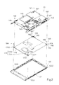
- Fig. 2 is an exploded perspective view of the tablet PC 10 shown in Fig. 1.
- the tablet PC 10 has a three-layer structure composed of a front cover 120, a LCD unit 130, and a rear cover 140 indicated in this order from the bottom in Fig. 2.
- the front cover 120 is occupied by a display window 121 in the center except for the frame portion surrounding the display window 121, and a transparent plastic plate is fit in the display window 121.
- the front cover 120 is to cover the front surface of the LCD unit 130.
- the LCD unit 130 is a display panel shaped like a plate, and its rear surface is shown in Fig. 2. As shown in Fig. 3, most of the front surface of the LCD unit 130 is occupied by a display screen 131 that is framed by a frame 132. Images are displayed on the display screen 131.
- the rear cover 140 covers the back surface of the LCD unit 130 so as to house the LCD unit 130 in cooperation with the front cover 120.
- the rear cover 140 has the function as a computer such as a CPU etc. and carries out various kinds of information processing including processing for displaying images on the display screen 131 (see Fig. 3) of the LCD unit 130.
- the LCD unit 130 has three screw-on hardware members 150, 160 and 170 being fixed thereto.
- the LCD unit 130 is fixed 170 by screws 181, 182, 183 and 184 to the front cover 120 via the screw-on hardware members 150, 160 and.
- the rear cover 140 is provided with concave portions 141, 142, 143, and 144 each having a clear hole for a screw and hiding the screw head.
- the rear cover 140 is fixed by screws 191, 192, 193 and 194 via the screw-on hardware members 150, 160 and 170 to the LCD unit 130 to which the front cover 120 has been fixed.
- the concave portions 141, 142, 143 and 144 hide the heads of the screws 191, 192, 193 and 194 in this state.
- the rear cover 140 is also provided with three other concave portions 145, 146 and 147 similar to the concave portions 141, 142, 143 and 144, which will be described later.
- Figs. 3 and 4 are perspective views each showing the LCD unit 130 with positions to which the screw-on hardware members 150, 160 and 170 are fixed.
- Fig. 3 shows the front surface and Fig. 4 shows the rear surface of the LCD unit 130.
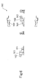
- Figs. 5, 6, and 7 are the respective six-view drawings of the screw-on hardware members 150, 160 and 170 shown in Figs. 3 and 4.
- the frame 132 of the LCD unit 130 has clear holes 1321, 1322, 1323 and 1324 for screws 301, 302, 303 and 304 to pass through them.
- the screw 301 is put through the clear hole 1321 and inserted into a screw hole 151 of the screw-on hardware member 150
- the screw 302 is put through the clear hole 1322 and inserted into a screw hole 161 of the screw-on hardware member 160
- the screws 303 and 304 are put through the clear holes 1323 and 1324 and inserted into screw holes 1711 and 1712 (see Fig. 4) of the screw-on hardware member 170, respectively.
- the three screw-on hardware members 150, 160 and 170 are thus secured to the LCD unit 130.
- the LCD unit 130 is fixed to the front cover 120.
- the LCD unit 130 is fixed to the front cover 120 in the following manner.
- the screw 181 is put through a clear hole 152 of the screw-on hardware member 150 that has been secured to the LCD unit 130 and inserted into a screw hole 1221 of the front cover 120.
- the screw 182 is put through a clear hole 162 of the screw-on hardware member 160 that has been secured to the LCD unit 130 and inserted into a screw hole 1222 of the front cover 120.
- the screws 183 and 184 are put through clear holes 1721 and 1722 of the screw-on hardware member 170 that has been secured to the LCD unit 130 and inserted into screw holes 1223 and 1224 of the front cover 120, respectively.
- the LCD unit 130 is this fixed do the front cover 120.
- the rear cover 140 is fixed to the LCD unit 130 in the following manner.
- the screw 191 is put through a clear hole of the concave portion 141 of the rear cover 140 and inserted into a screw hole 153 of the screw-on hardware member 150 that has been secured to the LCD unit 130 as well as the front cover 120.
- the screw 192 is put through a clear hole of the concave portion 142 of the rear cover 140 and inserted into a screw hole 163 of the screw-on member 160 that has been secured to the LCD unit 130 as well as the front cover 120.
- the screws 193 and 194 are put through clear holes of the concave portion 143 and 144 of the rear cover 140 and inserted into screw holes 1732 and 1732 of the screw-on hardware member 170 that has been secured to the LCD unit 130 as well as the front cover 120.
- the rear cover 140 is thus fixed to the LCD unit 130 so that the LCD unit 130 is secured between the front cover 120 and the rear cover 140.
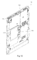
- Fig. 8 is an exploded perspective view showing the rear cover 140 and the LCD unit 130 that has been fixed to the front cover 120.
- the screw holes 153, 163 and 173 of the respective screw-on hardware members 150, 160 and 170 for fixing the rear cover 140 to the LCD unit 130 are disposed at the respective positions where the LCD unit 130 overlaps these screw holes in the vertical direction when the screw-on hardware members 150, 160 and 17 are fixed to the LCD unit 130.
- screw-on hardware members 150, 160 and 170 besides the screw-on hardware members 150, 160 and 170, three other screw-on hardware members 310, 320 and 330 are used for fixing the rear cover 140 to the front cover 120.
- the screw-on hardware members 310, 320 and 330 have clear holes through which screws 185, 186 and 187 are inserted respectively so that the screw-on hardware members 310, 320 and 330 are fixed to the front cover 120.
- the screw-on hardware members 310, 320 and 330 also have screw holes 311, 321 and 331 respectively for fixing the rear cover 140 to the front cover 120. Screws (not shown) are put through clear holes 145, 146 and 147 and inserted into the screw holes 311, 321 and 331 of the screw-on hardware members 310, 320 and 330 so that the rear cover 140 is more firmly fixed to the front cover 120.
- the screw holes 311, 321 and 331 of the screw-on hardware members 310, 320 and 330 are disposed at positions where the LCD unit 130 overlaps these screw holes and thus the tablet PC 10 is reduced in size.
- Fig. 9 is an exploded perspective view of a conventional tablet PC shown as a comparative example.
- the table PC in Fig. 9 is also composed of a front cover 520, a LCD unit 530 and a rear cover 540. Like Fig. 8 showing the tablet PC 10 of the present embodiment, Fig. 9 shows a state in which the LCD unit 530 has already been fixed to the front cover 520.
- Screw-on hardware members 551, 552, 553 and 554 are screwed on the LCD unit 530 and are then fixed to the front cover 520 by screws 581, 582, 583 and 584 so that the LCD unit 530 is fixed to the front cover 520.
- the front cover 520 has bosses 521, 522, 523 and 524 besides the screw-on hardware members 551, 552, 553 and 554.
- the bosses 521, 522, 523 and 524 have screw holes 531, 532, 533 and 534 used for fixing the rear cover 540 to the front cover 520.
- the rear cover 540 has concave portions 561, 562, 563 and 564 provided with clear holes at positions corresponding to the screw holes 531, 532, 533 and 534 respectively. Screws 571, 572, 573 and 574 are put through the clear holes of the concave portions 561, 562, 563 and 564 and inserted into the screw holes 531, 532, 533 and 534 of the front cover 520, respectively.
- the front cover 520 is thus fixed to the rear cover 540.
- the concave portions 561, 562, 563 and 564 hide the heads of the screws 571, 572, 573 and 574 respectively, i.e. these screw heads are sunk in the concave portions 561, 562, 563 and 564 when the front cover 520 is fixed to the rear cover 540.
- the screw holes 531, 532, 533 and 534 as well as the concave portions 561, 562, 563 and 564 used for uniting the front cover 520 and the rear cover 540 are provided outside the outer edge of the LCD unit 530.
- the front cover 520 and the rear cover 540 are much larger than the LCD unit 530 in size.
- the screw holes 153, 163 and 173 for fixing the rear cover 140 to the LCD unit 130 are provided in the screw-on hardware members 150, 160 and 170 for fixing the LCD unit 130 to the front cover 120 and further, the screw holes 153, 163 and 173 are disposed at positions where the LCD unit 130 overlaps these screw holes.
- the front cover 120 and the rear cover 140 can be reduced in size.
- the screw-on hardware members 150, 160 and 170 are screwed on the LCD unit 130 from both top and bottom as shown in Figs. 3 and 4. If another type of LCD unit that has screw holes used for the screw fastening is adopted, the shapes of screw-on hardware members are modified to become suitable for that type of LCD unit and the screw-on hardware members are screwed on its side surface.
- Fig. 10 shows the rear surface of the tablet PC 10 shown in Fig. 1.
- HDD cover 117 for covering a built-in hard disk drive (referred to as HDD hereinafter) is provided.
- Fig. 11 is an exploded perspective view showing HDD 420 and components around the HDD 420.
- the rear cover 140 of the tablet PC 10 has an opening 148 into which the HDD 420 is inserted.
- the HDD 420 If the HDD 420 is placed on the LCD 130 being exposed through the opening 148, the weight of the HDD 420 is put on the LCD unit 130, which causes disturbances in displays and failures. For this reason, the HDD 420 needs to be inserted into the opening 148 without applying the weight on the LCD unit 130.
- a box-shaped plate member 410 made of stainless thin plate is provided to solve such a problem.
- the plate member 410 is inserted into the opening 148 and supported by the edge of the opening 148.
- the HDD 420 is inserted into the plate member 410, a buffer member 430 is placed on the HDD 420, and the HDD cover 117 is fixed to the rear cover 140 over the buffer member 430.
- Fig. 12 is a perspective view of the plate member 410, in which part (A) of Fig. 12 illustrates the surface for receiving the HDD 420 (see Fig. 11) and part (B) of Fig. 12 illustrates the rear surface.
- Fig. 13 is a six-view drawing of the plate member 410.
- the plate member 410 is shaped like a box without a top surface and has an opening 411 in the center of the bottom.
- the plate member 410 is also provided with support surfaces 412 for supporting the HDD 420 (see Fig. 11) and defining the opening 411.
- the plate member 410 also has walls 413 supported by the bottom and flanges 414 projecting outward from the edge of the walls 413.
- the flanges 414 rest on the edge of the opening 148 so that the plate member 410 is supported by the edge of the opening 148.
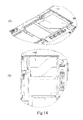
- Fig. 14 illustrates the opening 148 shown in Fig. 11, in which part (A) and part (B) are a perspective view and a plan view of the opening 148 respectively.
- Fig. 15 illustrates the plate member 410 being fit into the opening 148, in which part (A) and part (B) are a perspective view and a plan view thereof respectively.
- the plate member 410 is easily and elastically deformable because it is made of stainless thin plate and has the opening 411.
- the plate member 410 not only supports the HDD 420 but also protects it from shocks by functioning as a buffer material.
- the HDD 420 incorporates a hard disk therein (not shown) and has a structure in which the hard disk is rotated and accessed by a magnetic head disposed close to the hard disk. Thus it is vulnerable to shocks and needs to be sufficiently surrounded by a buffer material.
- the plate member 410 itself functions as a buffer material and thus it is possible to make buffer materials except the plate member 410 thinner.
- buffer materials 415 made of rubber are affixed to the support surfaces 412 and the walls 413.
- the HDD 420 is inserted into and supported by the plate member 410 via the buffer materials 415.
- the buffer member 430 is then placed on the HDD 420 that is inserted into the plate member 410.
- buffer materials 431 made of rubber are affixed to all corners of the buffer member 430.
- the buffer member 430 is covered by the HDD cover 117 via the buffer materials 431.
- the buffer materials 431 protect the HDD 420 from shocks received by the HDD cover 117.
- Fig. 16 is an exploded perspective view of a conventional tablet PC shown as a comparative example.
- the table PC shown in Fig. 16 also has a three-layer structure that is basically composed of a front cover, a LCD unit, and a rear cover.
- the rear cover has an opening 601 into which a HDD 620 is inserted.
- a hard plate that prevents the LCD unit from receiving the weight of the HDD 620.
- a buffer member 610 made of plastic and having buffer materials 611 affixed thereto, the HDD 620, and another buffer member 630 having buffer materials 631 affixed thereto are placed in this order. Then, a HDD cover 640 is fixed to the rear cover over the buffer member 630.
- the hard plate to fill the bottom 6011 of the opening 601 is required and it is necessary to use thick materials as the buffer materials 611 and 631 so that shocks can be absorbed only by these materials. Also, it is necessary to use a thick and less flexible plate as the buffer member 610. Accordingly, this structure requires quite large thickness as a whole, i.e. the size of the table PC becomes large in thickness, which does not satisfy the demand for miniaturization.
- Fig. 17 is an exploded perspective view of a conventional tablet PC shown as another comparative example. It
- the table PC shown in Fig. 17 also has a three-layer structure that is composed of a front cover, a LCD unit, and a rear cover.
- the rear cover has an opening 661 into which a HDD 670 is inserted, and a LCD unit 650 can bee seen through the opening 661. There, it is necessary to avoid applying the weight of the HDD 670 to the LCD unit 650.
- plate members 680 having buffer materials 681 affixed thereto are fixed on both sides of the HDD 670 so that the HDD 670 is supported by the sides without applying its weight to the LCD unit 650 when the HDD 670 is inserted into the opening 661.
- the opening 611 is covered by a HDD cover 662.
- the HDD 670 is supported at both sides thereof so that its size in thickness can be reduced, which satisfies the demand for small thickness.
- the plate members 680 are fixed on both sides of the HDD 670 so as to support the HDD 670, a substantially large space around the opening 661 is required to support the plate members 680. Such a structure does not satisfy the demand for miniaturization.
- the present embodiment provides a structure that satisfies the demand for both miniaturization and small thickness.
- Fig. 18 is an exploded perspective view of the LCD unit and the pen case composing the tablet PC 10 shown in Fig. 1.
- Fig. 18 the rear surface of the LCD unit 130 (see Figs. 3 and 4) is illustrated.
- the pen case 440 to be disposed on the rear surface of the LCD unit 130 and an inverter 450 supported by the pen case 440 are illustrated.
- the pen case 440 is used to house and keep the pen 13 shown in Fig. 1, and the pen 13 can be freely inserted into and pulled from the pen case 440.
- the inverter 450 is used to supply power to the LCD unit 130 by generating the power for turning on a backlight of the LCD unit 130 upon receipt of the power from the batter unit 12.
- Fig. 19 (A) and Fig. 19(B) are perspective views of the pen case 440 and the inverter 450 respectively.
- Fig. 19(A) illustrates a state in which the inverter 450 is fixed to the pen case 440
- Fig. 9(B) illustrates a state in which the inverter 450 and the pen case 440 are separate.
- pen-case fixing members 441 and 442 for fixing the pen case 440 are provided on both sides of the pen case 440 in the longitudinal direction.
- the pen-case fixing members 441 and 442 are fixed to the screw-on hardware members 310 and 150 shown in Fig. 8 so that the pen case 440 is fixed on the rear surface 135 of the LCD unit 130 while retaining the inverter 450.
- the inverter 450 is supported by the pen case 440 and arranged on the rear surface 135 of the LCD unit 130.
- a shield plate for preventing electromagnetic noise.
- the shield plate prevents noise generated by the inverter 450 from affecting the display of the LCD unit 130 and the detection of positions pointed by the pent 13.
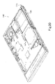
- Fig. 20 is a perspective view of the rear cover 140.
- Fig. 20 illustrates the inside of the rear cover 140, which faces the rear surface 135 of the LCD unit 130.
- the pen case 440 and the inverter 450 shown in Figs. 18 and 19 are housed in a housing area 149 in the rear cover 140.
- the pen 13 is inserted into or pulled from the pen case 440 through the pen opening 115 (see Fig. 1 also) .
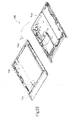
- Fig. 21 is a perspective view of the rear cover 140 and the LCD unit 130 being fixed to the front cover 120.
- the pen-case fixing members 441 and 442 being disposed on both sides of the pen case 440 are fixed to the screw-on hardware members 310 and 150, and the pen case 440 retaining the inverter 450 is arranged on the rear surface 135 of the LCD unit 130.
- the rear cover 140 is placed on the rear surface 135 in the direction shown by an arrow F.
- the pen case 440 and the inverter 450 are housed in the housing area 149.
- the pen case 440 can be arranged on the rear cover 140.
- the inverter 450 cannot be arranged on the rear cover 140 because it needs to be electrically connected to the LCD unit 130. If the inverter 450 is arranged on the rear cover 140, there arises a problem with respect to wiring to the LCD unit 130 when the rear cover 140 is fixed to the LCD unit 130. Thus, the inverter 450 needs to be arranged on the LCD 130 in a state where the rear cover 140 and the LCD unit 130 are separated as shown in Fig. 2. Accordingly, in the present embodiment, the pen case 440 is arranged on the LCD unit 130 and the inverter 450 is supported by the pen case 440.
- the inverter 450 is placed at a position where it overlaps the rear surface of the LCD unit 130 and thus the tablet PC is small and satisfies the demand for miniaturization.
- Fig. 22 is an exploded perspective view of a conventional tablet PC shown as a comparative example.
- Fig. 22 shows a LCD unit 730 being fixed on a front cover 720 and the inside of a rear cover 740.
- an inverter 750 is arranged beside the LCD unit 730 and fixed on the front cover 720.
- the rear cover 740 incorporates therein a CPU and various components such as circuit components for realizing the function of operating as a personal computer.
- the inverter 750 Since the rear cover 740 is placed on the LCD unit 730 in the direction shown by an arrow G, though the inverter 750 is not arranged on the rear surface of the LCD unit 730, there is provided a shield plate to prevent noise generated by various circuit components incorporated in the rear cover 740 from affecting the display of the LCD unit 730 the detection of positions pointed by a pen.
- the inverter 750 since the inverter 750 is arranged beside the LCD unit 730, noise generated by the inverter 750 cannot be shielded the shield date alone and thus other shield members are arranged on walls etc. surrounding the inverter 750. Accordingly, the structure shown in Fig. 22 not only fails to satisfy the demand for miniaturization but fails to prevent noise. Further, since such a structure requires shield members in addition to the shield plate arranged on the rear surface of the LCD unit 730, the number of components and the cost are increased.
- the inverter 450 is arranged on the LCD unit 130 and housed in the housing area 149 that is an empty space in the rear cover 140. Therefore, the present embodiment is successful not only in miniaturization but also in preventing noise.
Landscapes
- Engineering & Computer Science (AREA)
- Theoretical Computer Science (AREA)
- Computer Hardware Design (AREA)
- General Engineering & Computer Science (AREA)
- Human Computer Interaction (AREA)
- General Physics & Mathematics (AREA)
- Physics & Mathematics (AREA)
- Power Engineering (AREA)
- Devices For Indicating Variable Information By Combining Individual Elements (AREA)
- Casings For Electric Apparatus (AREA)
- Liquid Crystal (AREA)
- Control Of Indicators Other Than Cathode Ray Tubes (AREA)
- Controls And Circuits For Display Device (AREA)
- Combined Means For Separation Of Solids (AREA)
Abstract
Description
- The present invention relates to an electronic apparatus having a screen.
- Recently, a pen personal computer known as a tablet personal computer (referred to as a "tablet PC" hereinafter) has been designed and introduced as a product.
- A tablet PC is square and flat in shape, and it has a large screen for accepting user input by detecting a point touched by or approached by a pen.
- A tablet PC generally has a three-layer structure in which a display panel such as a LCD panel is disposed between a front cover and a rear cover.
-
Japanese Patent Application Laid-Open No. 5-150224 - A tablet PC has been developed to realize user input such as user input by means of a pen, onto which a user inputs information while holding it in his hand. It is desired to enlarge the screen of the tablet PC so as to increase an amount of information to be displayed and to improve usability, while it is desired to miniaturize the tablet PC itself for portability. The flat surface of the tablet PC having a screen thereon cannot be smaller than the screen. Thus, it is desired to miniaturize the tablet PC so that the screen is enlarged as far to the edge of the flat surface of the tablet PC as possible and an area surrounding the screen on the flat surface of the tablet PC is formed as small as possible. Also, it is desired to form the flat surface of the tablet PC as small as possible in thickness.
- For example, a flat surface of the display panel unit shown in
Japanese Patent Application Laid-Open No. 5-150224 - In view of the foregoing, it is an object of the present invention to provide a thin and small electronic apparatus such as tablet PC.
- In order to achieve the above object the present invention provides a first electronic apparatus having:
- a plate-shaped display panel that has a screen on a front surface thereof;
- a first cover that has a display window at a position facing the screen and covers one surface of the display panel; and
- a second cover that covers the other surface of the display panel so as to house the display panel in cooperation with the first cover,
- the electronic apparatus including:
- a fastening member that has a first hole via which the fastening member is fixed to a periphery of the display panel, a second hole via which the fastening member is fixed to the first cover, and a third hole via which the fastening member is fixed to the second cover,
- In the first electronic apparatus, it is preferable that the third hole is a screw hole, and the second cover is fixed to the fastening member by a screw inserted into the screw hole.
- In order to achieve the above object, the present invention provides a second electronic apparatus having:
- a plate-shaped display panel that has a screen on a front surface thereof;
- a first cover that has a display window at a position facing the screen and covers one surface of the display panel; and
- a second cover that covers the other surface of the display panel so as to house the display panel in cooperation with the first cover,
- the electronic apparatus including:
- an fastening member that has a fourth hole via which the fastening member is fixed to the first cover, and a fifth hole via which the fastening member is fixed to the second cover
- In the second electronic apparatus, it is preferable that the fifth hole is a screw hole, and the second cover is fixed to the fastening member by a screw inserted the screw hole.
- In order to achieve the above object, the present invention provides a third electronic apparatus having:
- a plate-shaped display panel that has a screen on a front surface thereof;
- a first cover that has a display window at a position facing the screen and covers one surface of the display panel; and
- a second cover that covers the other surface of the display panel so as to house the display panel in cooperation with the first cover, wherein:
- the second cover is provided with an opening and includes:
- a box-shaped plate member that has an open space in a center of a bottom thereof and is fit into the opening so as to be supported by an edge of the opening; and
- a disk unit that drives a disk type of recording medium and is disposed in the opening in such a manner that the disk unit is fit into the plate member and supported by a periphery the bottom of the plate member.
- the second cover is provided with an opening and includes:
- In the third electronic apparatus, the disk unit includes a hard disk therein and drives the hard disk.
- In order to achieve the above object, the present invention provides a fourth electronic apparatus having:
- a plate-shaped display panel that has a screen on a front surface thereof;
- a first cover that has a display window at a position facing the screen and covers one surface of the display panel; and
- a second cover that covers the other surface of the display panel so as to house the display panel in cooperation with the first cover,
- the electronic apparatus including:
- a power converter that coverts, upon receipt of power, the power into power to be supplied to the display panel,
- In the fourth electronic apparatus, the display panel includes a function of accepting pen input by detecting a position touched by or approached by a pen,
wherein the electronic apparatus comprises a pen case that is fixed to the first cover and disposed at a position where the pen case overlaps a rear surface of the display panel, and
wherein the power converter is fixed to the pen case and fixed to the first cover via the pen case. - In the fourth electronic apparatus, the power converter is an inverter that supplies power for backlighting the screen.
- In the first and the second electronic apparatus, the fastening member is a hardware member. The first through fourth electronic apparatus have an information processing function including an image display processing function for the screen.
- In order to achieve the above object, the present invention provides a fifth electronic apparatus having:
- a plate-shaped display panel that has a screen on a front surface thereof;
- a first cover that has a display window at a position facing the screen and covers one surface of the display panel; and
- a second cover that has an information processing function including an image display processing function for the screen and covers the other surface of the display panel so as to house the display panel in cooperation with the first cover,
- the electronic apparatus including:
- a fastening member that has a first hole via which the fastening member is fixed to a periphery of the display panel, a second hole via which the fastening member is fixed to the first cover, and a third hole via which the fastening member is fixed to the second cover,
- In order to achieve the above object, the present invention provides a sixth electronic apparatus having:
- a plate-shaped display panel that has a screen on a front surface thereof;
- a first cover that has a display window at a position facing the screen and covers one surface of the display panel; and
- a second cover that has an information processing function including an image display processing function for the screen and covers the other surface of the display panel so as to house the display panel in cooperation with the first cover,
- the electronic apparatus including:
- a fastening member that has a first hole via which the fastening member is fixed to a periphery of the display panel, a second hole via which the fastening member is fixed to the first cover, and a third hole via which the fastening member is fixed to the second cover,
- In order to achieve the above object, the present invention provides a seventh electronic apparatus having:
- a plate-shaped display panel that has a screen on a front surface thereof;
- a first cover that has a display window at a position facing the screen and covers one surface of the display panel; and
- a second cover that covers the other surface of the display panel so as to house the display panel in cooperation with the first cover,
- the electronic apparatus including:
- a fastening member that has a fourth hole via which the fastening member is fixed to the first cover, and a fifth hole via which the fastening member is fixed to the second cover,
- According to the first electronic apparatus of the present invention, the fastening member having the first through third holes has the third hole at a position where the third hole overlaps the display panel, and thus the second cover is fixed to the fastening member in a position where the second cover overlaps the display panel. Accordingly, it is possible to make the area around the flat surface of the display panel small, which contributes to miniaturization of the electronic apparatus.
- According to the second electronic apparatus of the present invention, when the fastening member having the fourth and fifth holes is used, the second cover can be firmly fixed by screws.
- Also, according to the third electronic apparatus of the present invention, the plate member can be made of thin plate and functions as a kind of cushion material. Thus, it is possible to use extremely thin cushion materials that need to be arranged around the disk unit and are usually thick, which contributes to making this electronic apparatus small in thickness.
- Further, according to the fourth electronic apparatus of the present invention, the power converter that is necessary to power supply for the display panel is disposed on the back of the display panel so as to overlap the display panel. Thus, the area around the flat surface of the display panel can be smaller than an apparatus of which a display panel and a power converter are arranged side by side. This also contributes to miniaturization of this electronic apparatus.
- Furthermore, according to the fifth electronic apparatus of the present invention, since the above-described fastening member to which the second cover is fixed is provided, there is no need for the first cover to have a large boss that is used to attach a rear cover to a front cover as required by a conventional technique. This allows a frame to become small and contributes to miniaturization of the apparatus.
- Furthermore, according to the sixth and seventh electronic apparatus of the present invention, the fastening member has a hole for fixing itself to the second cover and the hole is provided in a square area including the display panel and the fastening member, which also allows the frame to become small and contributes to of the electronic apparatus.
-
- Fig. 1 is an exploded perspective view showing a structure of a PC system including a tablet PC according to one embodiment of the present invention.
- Fig. 2 is an exploded perspective view of the tablet PC shown in Fig. 1.
- Fig. 3 is an exploded perspective view showing positions on a LCD unit at which screw-on hardware members are fixed.
- Fig. 4 is an exploded perspective view showing positions of a LCD unit at which screw-on hardware members are fixed.
- Fig. 5 is a six-view drawing of a screw-on hardware member.
- Fig. 6 is a six-view drawing of a screw-on hardware member.
- Fig. 7 is a six-view drawing of a screw-on hardware member.
- Fig. 8 is an exploded perspective view showing a rear cover and a LCD unit that has been fixed to a front cover.
- Fig. 9 is an exploded perspective view of a conventional tablet PC shown as a comparative example.
- Fig. 10 is a view showing the rear surface of the tablet PC shown in Fig. 1.
- Fig. 11 is an exploded perspective view showing a HDD and components around the HDD of the tablet PC shown in Fig. 1.
- Fig. 12 is a perspective view of a plate member.
- Fig. 13 is a six-view drawing of a plate member.
- Fig. 14 is a view showing an opening shown in Fig. 11, in which part (A) is a perspective view and part (B) is a plan view thereof.
- Fig. 15 a view showing a plate member being fit into an opening, in which part (A) is a perspective view and part (B) is a plan view thereof.
- Fig. 16 is an exploded perspective view of a conventional tablet PC shown as a comparative example.
- Fig. 17 is an exploded perspective view of a conventional tablet PC shown as another comparative example.
- Fig. 18 is an exploded perspective view of the LCD unit and a pen case composing the tablet PC shown in Fig. 1.
- Fig. 19(A) is a perspective view of a pen case.
- Fig. 19(B) is a perspective view of an inverter.
- Fig. 20 is a perspective view of a rear cover.
- Fig. 21 is a perspective view of a rear cover and a LCD unit being fixed to a front cover.
- Fig. 22 is an exploded perspective view of a conventional tablet PC shown as a comparative example.
- Hereinafter, embodiments of the present invention will be described.
- Fig. 1 is an exploded perspective view showing an entire structure of a PC system 1 including a
tablet PC 10 according to one embodiment of the present invention. - The PC system 1 is comprised of the
tablet PC 10 and adocking unit 20. - The
tablet PC 10 is comprised of amain unit 11, abattery unit 12, and apen 13. All the front surface of themain unit 10 is occupied by adisplay 111 except for a frame portion surrounding thedisplay 111. The frame portion has various types of I/O connectors 112 and operatingbuttons 113. The frame portion also has aninfrared communications portion 114 used for infrared communications with a wireless keyboard and a wireless microphone (not shown). Further, the frame portion is provided with apen opening 115 through which apen 13 is inserted. Themain unit 11 contains therein a pen case (as will be described later) that is disposed behind thepen opening 115. Thepen 13 is inserted into the pen case in the direction shown by an arrow A through theopening 115 so as to be contained in themain unit 11. - The
battery unit 12 is connected to themain unit 11 in the direction shown by an arrow B and thus themain unit 11 is capable of operating by receiving power from thebattery unit 12. - A user pulls the
pen 13 from the pen case when he wants to use it and touches thescreen 111 with its tip to input information. Thetablet PC 10 is configured to detect a coordinate of a point touched by thepen 13 on thescreen 111 through electromagnetic induction between thepen 13 and themain unit 11. An operating system (OS) is installed on the tablet PC, which is suitable for input operations by a user who inputs various kinds of information and orders into thetablet PC 10 by rubbing the tip of thepen 13 against thescreen 111. When inputting complicated information etc., a keyboard can be displayed on the screen so that a user can input information by touching keys thereon with the tip of the pen. - The
tablet PC 10 is detachably supported thedocking unit 20 and thus the screen of thetablet PC 10 can be used like a display of an ordinary type of personal computer when thetablet PC 10 is obliquely and firmly set on thedocking unit 20. When thetablet PC 10 is firmly set on thedocking unit 20 and a wireless keyboard and a wireless mouse (not shown) are prepared, thetablet PC 10 can be used like an ordinary type of personal computer. - The
docking unit 20 has asupport portion 21 for supporting thetablet PC 10, and thesupport portion 21 has aconnector 211 to be connected to a connector 116 (see Fig. 10) provided on the rear surface of thetablet PC 10. Also, on both sides of thesupport portion 21, holdingportions 212 for holding the sides of thetablet PC 10 are provided. When thetablet PC 10 is connected to thedocking unit 20 via thesupport portion 21 in the direction shown by an arrow C, theconnector 116 disposed on the back of thetablet PC 10 and theconnector 211 of thesupport portion 21 are connected and thetablet PC 10 is held by the holdingportions 212 at the sides. Thetablet PC 10 and thesupport portion 21 are thus firmly connected so as to become one unit. Thesupport portion 21 can be turned by 90 degrees in the direction shown by an arrow D and thus the screen oftablet PC 10 that is portrait as shown in Fig. 10 can be used as a landscape screen. - The
docking unit 20 has aconcave portion 23 in which adrive unit 24, such as a CD-ROM drive unit, a CD-R drive unit, a DVD drive unit selected by a user when necessary, is fit in the direction shown by an arrow E. - The feature of the present embodiment resides in the
tablet PC 10 of the PC system 1 shown in Fig. 1 and thus thetablet PC 10 will be described in detail hereinafter. - Fig. 2 is an exploded perspective view of the
tablet PC 10 shown in Fig. 1. - The
tablet PC 10 has a three-layer structure composed of afront cover 120, aLCD unit 130, and arear cover 140 indicated in this order from the bottom in Fig. 2. - The
front cover 120 is occupied by adisplay window 121 in the center except for the frame portion surrounding thedisplay window 121, and a transparent plastic plate is fit in thedisplay window 121. Thefront cover 120 is to cover the front surface of theLCD unit 130. - The
LCD unit 130 is a display panel shaped like a plate, and its rear surface is shown in Fig. 2. As shown in Fig. 3, most of the front surface of theLCD unit 130 is occupied by adisplay screen 131 that is framed by aframe 132. Images are displayed on thedisplay screen 131. - The
rear cover 140 covers the back surface of theLCD unit 130 so as to house theLCD unit 130 in cooperation with thefront cover 120. Therear cover 140 has the function as a computer such as a CPU etc. and carries out various kinds of information processing including processing for displaying images on the display screen 131 (see Fig. 3) of theLCD unit 130. - The
LCD unit 130 has three screw-onhardware members LCD unit 130 is fixed 170 byscrews front cover 120 via the screw-onhardware members rear cover 140 is provided withconcave portions rear cover 140 is fixed byscrews hardware members LCD unit 130 to which thefront cover 120 has been fixed. Theconcave portions screws - The
rear cover 140 is also provided with three otherconcave portions concave portions - Figs. 3 and 4 are perspective views each showing the
LCD unit 130 with positions to which the screw-onhardware members - Fig. 3 shows the front surface and Fig. 4 shows the rear surface of the
LCD unit 130. - Figs. 5, 6, and 7 are the respective six-view drawings of the screw-on
hardware members - The
frame 132 of theLCD unit 130 hasclear holes screws screw 301 is put through theclear hole 1321 and inserted into ascrew hole 151 of the screw-onhardware member 150, thescrew 302 is put through theclear hole 1322 and inserted into ascrew hole 161 of the screw-onhardware member 160, and thescrews clear holes screw holes 1711 and 1712 (see Fig. 4) of the screw-onhardware member 170, respectively. The three screw-onhardware members LCD unit 130. - Subsequently, by means of the screw-on
hardware members LCD unit 130, theLCD unit 130 is fixed to thefront cover 120. - As shown in Fig. 2, the
LCD unit 130 is fixed to thefront cover 120 in the following manner. Thescrew 181 is put through aclear hole 152 of the screw-onhardware member 150 that has been secured to theLCD unit 130 and inserted into a screw hole 1221 of thefront cover 120.
Thescrew 182 is put through aclear hole 162 of the screw-onhardware member 160 that has been secured to theLCD unit 130 and inserted into ascrew hole 1222 of thefront cover 120. Thescrews clear holes hardware member 170 that has been secured to theLCD unit 130 and inserted intoscrew holes front cover 120, respectively. TheLCD unit 130 is this fixed do thefront cover 120. - Also, as shown in Fig. 2, the
rear cover 140 is fixed to theLCD unit 130 in the following manner. Thescrew 191 is put through a clear hole of theconcave portion 141 of therear cover 140 and inserted into ascrew hole 153 of the screw-onhardware member 150 that has been secured to theLCD unit 130 as well as thefront cover 120. Thescrew 192 is put through a clear hole of theconcave portion 142 of therear cover 140 and inserted into ascrew hole 163 of the screw-onmember 160 that has been secured to theLCD unit 130 as well as thefront cover 120. Thescrews concave portion rear cover 140 and inserted intoscrew holes hardware member 170 that has been secured to theLCD unit 130 as well as thefront cover 120. Therear cover 140 is thus fixed to theLCD unit 130 so that theLCD unit 130 is secured between thefront cover 120 and therear cover 140. - Fig. 8 is an exploded perspective view showing the
rear cover 140 and theLCD unit 130 that has been fixed to thefront cover 120. - The screw holes 153, 163 and 173 of the respective screw-on
hardware members rear cover 140 to theLCD unit 130 are disposed at the respective positions where theLCD unit 130 overlaps these screw holes in the vertical direction when the screw-onhardware members LCD unit 130. By providing the screw holes 153, 163 and 173 at such positions, it is possible to shrink the area of thefront cover 120 and therear cover 140, which surrounds the outer edge of theLCD unit 130, and thus thetablet PC 10 can be reduced in size. This feature will be described later again using a comparative example. - In the present embodiment, as shown in Fig. 8, besides the screw-on
hardware members hardware members rear cover 140 to thefront cover 120. The screw-onhardware members hardware members front cover 120. - The screw-on
hardware members screw holes rear cover 140 to thefront cover 120. Screws (not shown) are put throughclear holes hardware members rear cover 140 is more firmly fixed to thefront cover 120. - Like the screw holes 153, 163 and 173 of the screw-on
hardware members hardware members LCD unit 130 overlaps these screw holes and thus thetablet PC 10 is reduced in size. - Fig. 9 is an exploded perspective view of a conventional tablet PC shown as a comparative example.
- The table PC in Fig. 9 is also composed of a
front cover 520, aLCD unit 530 and arear cover 540. Like Fig. 8 showing thetablet PC 10 of the present embodiment, Fig. 9 shows a state in which theLCD unit 530 has already been fixed to thefront cover 520. - Screw-on
hardware members LCD unit 530 and are then fixed to thefront cover 520 byscrews LCD unit 530 is fixed to thefront cover 520. - The
front cover 520 hasbosses hardware members bosses screw holes rear cover 540 to thefront cover 520. Therear cover 540 hasconcave portions Screws concave portions front cover 520, respectively. Thefront cover 520 is thus fixed to therear cover 540. Theconcave portions screws concave portions front cover 520 is fixed to therear cover 540. - In the example shown in Fig. 9, the screw holes 531, 532, 533 and 534 as well as the
concave portions front cover 520 and therear cover 540 are provided outside the outer edge of theLCD unit 530. Thus, thefront cover 520 and therear cover 540 are much larger than theLCD unit 530 in size. - On the contrary, in the embodiment shown in Figs. 1 through 8, the screw holes 153, 163 and 173 for fixing the
rear cover 140 to theLCD unit 130 are provided in the screw-onhardware members LCD unit 130 to thefront cover 120 and further, the screw holes 153, 163 and 173 are disposed at positions where theLCD unit 130 overlaps these screw holes. Thus thefront cover 120 and therear cover 140 can be reduced in size. - In the embodiment described above, the screw-on
hardware members LCD unit 130 from both top and bottom as shown in Figs. 3 and 4. If another type of LCD unit that has screw holes used for the screw fastening is adopted, the shapes of screw-on hardware members are modified to become suitable for that type of LCD unit and the screw-on hardware members are screwed on its side surface. - Fig. 10 shows the rear surface of the
tablet PC 10 shown in Fig. 1. - In this rear surface, a
HDD cover 117 for covering a built-in hard disk drive (referred to as HDD hereinafter) is provided. - Fig. 11 is an exploded perspective
view showing HDD 420 and components around theHDD 420. - As shown in Fig. 11, the
rear cover 140 of thetablet PC 10 has anopening 148 into which theHDD 420 is inserted. - If the
HDD 420 is placed on theLCD 130 being exposed through theopening 148, the weight of theHDD 420 is put on theLCD unit 130, which causes disturbances in displays and failures. For this reason, theHDD 420 needs to be inserted into theopening 148 without applying the weight on theLCD unit 130. - A box-shaped
plate member 410 made of stainless thin plate is provided to solve such a problem. Theplate member 410 is inserted into theopening 148 and supported by the edge of theopening 148. TheHDD 420 is inserted into theplate member 410, abuffer member 430 is placed on theHDD 420, and theHDD cover 117 is fixed to therear cover 140 over thebuffer member 430. - Fig. 12 is a perspective view of the
plate member 410, in which part (A) of Fig. 12 illustrates the surface for receiving the HDD 420 (see Fig. 11) and part (B) of Fig. 12 illustrates the rear surface. - Fig. 13 is a six-view drawing of the
plate member 410. - The
plate member 410 is shaped like a box without a top surface and has anopening 411 in the center of the bottom. Theplate member 410 is also provided withsupport surfaces 412 for supporting the HDD 420 (see Fig. 11) and defining theopening 411. - The
plate member 410 also haswalls 413 supported by the bottom andflanges 414 projecting outward from the edge of thewalls 413. When theplate member 410 is fit into theopening 148 shown in Fig. 1, theflanges 414 rest on the edge of theopening 148 so that theplate member 410 is supported by the edge of theopening 148. - Fig. 14 illustrates the
opening 148 shown in Fig. 11, in which part (A) and part (B) are a perspective view and a plan view of theopening 148 respectively. Fig. 15 illustrates theplate member 410 being fit into theopening 148, in which part (A) and part (B) are a perspective view and a plan view thereof respectively. - The
plate member 410 is easily and elastically deformable because it is made of stainless thin plate and has theopening 411. Theplate member 410 not only supports theHDD 420 but also protects it from shocks by functioning as a buffer material. TheHDD 420 incorporates a hard disk therein (not shown) and has a structure in which the hard disk is rotated and accessed by a magnetic head disposed close to the hard disk. Thus it is vulnerable to shocks and needs to be sufficiently surrounded by a buffer material. In the present embodiment, theplate member 410 itself functions as a buffer material and thus it is possible to make buffer materials except theplate member 410 thinner. - As shown in Figs. 11 and 15,
buffer materials 415 made of rubber are affixed to the support surfaces 412 and thewalls 413. TheHDD 420 is inserted into and supported by theplate member 410 via thebuffer materials 415. - The
buffer member 430 is then placed on theHDD 420 that is inserted into theplate member 410. - As shown in Fig. 11,
buffer materials 431 made of rubber are affixed to all corners of thebuffer member 430. Thebuffer member 430 is covered by theHDD cover 117 via thebuffer materials 431. Thebuffer materials 431 protect theHDD 420 from shocks received by theHDD cover 117. - Fig. 16 is an exploded perspective view of a conventional tablet PC shown as a comparative example.
- The table PC shown in Fig. 16 also has a three-layer structure that is basically composed of a front cover, a LCD unit, and a rear cover. The rear cover has an
opening 601 into which aHDD 620 is inserted. In abottom 6011 of theopening 601, there is provided a hard plate that prevents the LCD unit from receiving the weight of theHDD 620. - In the
opening 601, abuffer member 610 made of plastic and havingbuffer materials 611 affixed thereto, theHDD 620, and anotherbuffer member 630 havingbuffer materials 631 affixed thereto are placed in this order. Then, aHDD cover 640 is fixed to the rear cover over thebuffer member 630. - In a structure in this example, the hard plate to fill the
bottom 6011 of theopening 601 is required and it is necessary to use thick materials as thebuffer materials buffer member 610. Accordingly, this structure requires quite large thickness as a whole, i.e. the size of the table PC becomes large in thickness, which does not satisfy the demand for miniaturization. - Fig. 17 is an exploded perspective view of a conventional tablet PC shown as another comparative example. It
- The table PC shown in Fig. 17 also has a three-layer structure that is composed of a front cover, a LCD unit, and a rear cover. The rear cover has an
opening 661 into which aHDD 670 is inserted, and aLCD unit 650 can bee seen through theopening 661. There, it is necessary to avoid applying the weight of theHDD 670 to theLCD unit 650. Thus,plate members 680 havingbuffer materials 681 affixed thereto are fixed on both sides of theHDD 670 so that theHDD 670 is supported by the sides without applying its weight to theLCD unit 650 when theHDD 670 is inserted into theopening 661. After theHDD 670 is placed in theopening 611, theopening 611 is covered by aHDD cover 662. - In the example shown in Fig. 17, the
HDD 670 is supported at both sides thereof so that its size in thickness can be reduced, which satisfies the demand for small thickness. However, since theplate members 680 are fixed on both sides of theHDD 670 so as to support theHDD 670, a substantially large space around theopening 661 is required to support theplate members 680. Such a structure does not satisfy the demand for miniaturization. - In the embodiment of the present invention described by reference to Figs. 11 through 15, there is no need to provide a space much larger than the overall size of the
HDD 420 around theopening 148. In addition, since thethin plate member 410 is provided and its elasticity is utilized, thebuffer materials table PC 10 is small in thickness. Therefore, the present embodiment provides a structure that satisfies the demand for both miniaturization and small thickness. - Fig. 18 is an exploded perspective view of the LCD unit and the pen case composing the
tablet PC 10 shown in Fig. 1. - In Fig. 18, the rear surface of the LCD unit 130 (see Figs. 3 and 4) is illustrated. Above the
LCD unit 130, thepen case 440 to be disposed on the rear surface of theLCD unit 130 and aninverter 450 supported by thepen case 440 are illustrated. - The
pen case 440 is used to house and keep thepen 13 shown in Fig. 1, and thepen 13 can be freely inserted into and pulled from thepen case 440. Theinverter 450 is used to supply power to theLCD unit 130 by generating the power for turning on a backlight of theLCD unit 130 upon receipt of the power from thebatter unit 12. - Fig. 19 (A) and Fig. 19(B) are perspective views of the
pen case 440 and theinverter 450 respectively. Fig. 19(A) illustrates a state in which theinverter 450 is fixed to thepen case 440, and Fig. 9(B) illustrates a state in which theinverter 450 and thepen case 440 are separate. - On both sides of the
pen case 440 in the longitudinal direction, pen-case fixing members pen case 440 are provided. The pen-case fixing members hardware members pen case 440 is fixed on therear surface 135 of theLCD unit 130 while retaining theinverter 450. - As shown in Figs. 18 and 19(A), the
inverter 450 is supported by thepen case 440 and arranged on therear surface 135 of theLCD unit 130. On therear surface 135 of theLCD unit 130, there is provided a shield plate for preventing electromagnetic noise. Although theinverter 450 is a kind of noise source, the shield plate prevents noise generated by theinverter 450 from affecting the display of theLCD unit 130 and the detection of positions pointed by thepent 13. - Fig. 20 is a perspective view of the
rear cover 140. - Fig. 20 illustrates the inside of the
rear cover 140, which faces therear surface 135 of theLCD unit 130. - The
pen case 440 and theinverter 450 shown in Figs. 18 and 19 are housed in ahousing area 149 in therear cover 140. Thepen 13 is inserted into or pulled from thepen case 440 through the pen opening 115 (see Fig. 1 also) . - Fig. 21 is a perspective view of the
rear cover 140 and theLCD unit 130 being fixed to thefront cover 120. - The pen-
case fixing members pen case 440 are fixed to the screw-onhardware members pen case 440 retaining theinverter 450 is arranged on therear surface 135 of theLCD unit 130. - The
rear cover 140 is placed on therear surface 135 in the direction shown by an arrow F. Thepen case 440 and theinverter 450 are housed in thehousing area 149. - The
pen case 440 can be arranged on therear cover 140. However, theinverter 450 cannot be arranged on therear cover 140 because it needs to be electrically connected to theLCD unit 130. If theinverter 450 is arranged on therear cover 140, there arises a problem with respect to wiring to theLCD unit 130 when therear cover 140 is fixed to theLCD unit 130. Thus, theinverter 450 needs to be arranged on theLCD 130 in a state where therear cover 140 and theLCD unit 130 are separated as shown in Fig. 2. Accordingly, in the present embodiment, thepen case 440 is arranged on theLCD unit 130 and theinverter 450 is supported by thepen case 440. - The
inverter 450 is placed at a position where it overlaps the rear surface of theLCD unit 130 and thus the tablet PC is small and satisfies the demand for miniaturization. - Fig. 22 is an exploded perspective view of a conventional tablet PC shown as a comparative example.
- Like Fig. 21 showing the present embodiment. Fig. 22 shows a
LCD unit 730 being fixed on afront cover 720 and the inside of arear cover 740. - In the comparative example shown in Fig. 22, an
inverter 750 is arranged beside theLCD unit 730 and fixed on thefront cover 720. - In this case, even if there is an empty space in the
rear cover 740, it remains dead, and thefront cover 740 needs a space large enough to accommodate theLCD unit 730 and theinverter 750 arranged side by side. As a result, the tablet PC is large in size. In addition, therear cover 740 incorporates therein a CPU and various components such as circuit components for realizing the function of operating as a personal computer. Since therear cover 740 is placed on theLCD unit 730 in the direction shown by an arrow G, though theinverter 750 is not arranged on the rear surface of theLCD unit 730, there is provided a shield plate to prevent noise generated by various circuit components incorporated in therear cover 740 from affecting the display of theLCD unit 730 the detection of positions pointed by a pen. However, since theinverter 750 is arranged beside theLCD unit 730, noise generated by theinverter 750 cannot be shielded the shield date alone and thus other shield members are arranged on walls etc. surrounding theinverter 750. Accordingly, the structure shown in Fig. 22 not only fails to satisfy the demand for miniaturization but fails to prevent noise. Further, since such a structure requires shield members in addition to the shield plate arranged on the rear surface of theLCD unit 730, the number of components and the cost are increased. - On the contrary, in the present embodiment, as shown in Fig. 21 for example, the
inverter 450 is arranged on theLCD unit 130 and housed in thehousing area 149 that is an empty space in therear cover 140. Therefore, the present embodiment is successful not only in miniaturization but also in preventing noise.
Claims (4)
- An electronic apparatus including:a plate-shaped display panel that has a screen on a front surface thereof;a first cover that has a display window at a position facing the screen and covers one surface of the display panel; anda second cover that covers the other surface of the display panel so as to house the display panel in cooperation with the first cover,the electronic apparatus comprising:wherein the fastening member has the second hole at a position where the second hole overlaps the display panel when the display panel is fixed to the first cover and the fastening member is fixed to the first cover.a fastening member that has a first hole via which the fastening member is fixed to the first cover, and a second hole via which the fastening member is fixed to the second cover,
- An electronic apparatus according to claim 1 wherein the second hole is a screw hole, and the second cover is fixed to the fastening member by a screw inserted into the screw hole.
- An electronic apparatus according to claim 1, wherein the fastening member is a hardware member.
- An electronic apparatus according to claim 1, has an information processing function including an image display processing function for the screen.
Applications Claiming Priority (2)
| Application Number | Priority Date | Filing Date | Title |
|---|---|---|---|
| JP2003417157A JP2005173509A (en) | 2003-12-15 | 2003-12-15 | Electronic apparatus |
| EP04255240A EP1544714B1 (en) | 2003-12-15 | 2004-08-31 | Electronic apparatus |
Related Parent Applications (1)
| Application Number | Title | Priority Date | Filing Date |
|---|---|---|---|
| EP04255240A Division EP1544714B1 (en) | 2003-12-15 | 2004-08-31 | Electronic apparatus |
Publications (3)
| Publication Number | Publication Date |
|---|---|
| EP1847904A2 true EP1847904A2 (en) | 2007-10-24 |
| EP1847904A3 EP1847904A3 (en) | 2007-12-05 |
| EP1847904B1 EP1847904B1 (en) | 2009-03-11 |
Family
ID=34510601
Family Applications (7)
| Application Number | Title | Priority Date | Filing Date |
|---|---|---|---|
| EP07112406A Withdrawn EP1847909A3 (en) | 2003-12-15 | 2004-08-31 | Electronic apparatus |
| EP07112402A Withdrawn EP1847905A3 (en) | 2003-12-15 | 2004-08-31 | Electronic apparatus |
| EP07112404A Expired - Fee Related EP1847907B1 (en) | 2003-12-15 | 2004-08-31 | Electronic apparatus |
| EP07112405A Expired - Fee Related EP1847908B1 (en) | 2003-12-15 | 2004-08-31 | Electronic apparatus |
| EP04255240A Expired - Fee Related EP1544714B1 (en) | 2003-12-15 | 2004-08-31 | Electronic apparatus |
| EP07112401A Expired - Fee Related EP1847904B1 (en) | 2003-12-15 | 2004-08-31 | Electronic apparatus |
| EP07112403A Withdrawn EP1847906A3 (en) | 2003-12-15 | 2004-08-31 | Electronic apparatus |
Family Applications Before (5)
| Application Number | Title | Priority Date | Filing Date |
|---|---|---|---|
| EP07112406A Withdrawn EP1847909A3 (en) | 2003-12-15 | 2004-08-31 | Electronic apparatus |
| EP07112402A Withdrawn EP1847905A3 (en) | 2003-12-15 | 2004-08-31 | Electronic apparatus |
| EP07112404A Expired - Fee Related EP1847907B1 (en) | 2003-12-15 | 2004-08-31 | Electronic apparatus |
| EP07112405A Expired - Fee Related EP1847908B1 (en) | 2003-12-15 | 2004-08-31 | Electronic apparatus |
| EP04255240A Expired - Fee Related EP1544714B1 (en) | 2003-12-15 | 2004-08-31 | Electronic apparatus |
Family Applications After (1)
| Application Number | Title | Priority Date | Filing Date |
|---|---|---|---|
| EP07112403A Withdrawn EP1847906A3 (en) | 2003-12-15 | 2004-08-31 | Electronic apparatus |
Country Status (6)
| Country | Link |
|---|---|
| US (1) | US7184260B2 (en) |
| EP (7) | EP1847909A3 (en) |
| JP (1) | JP2005173509A (en) |
| KR (1) | KR100644306B1 (en) |
| CN (3) | CN100394351C (en) |
| DE (4) | DE602004019712D1 (en) |
Cited By (1)
| Publication number | Priority date | Publication date | Assignee | Title |
|---|---|---|---|---|
| EP2101244A1 (en) * | 2008-02-29 | 2009-09-16 | Giga-Byte Technology Co., Ltd. | Separable multimedia apparatus |
Families Citing this family (18)
| Publication number | Priority date | Publication date | Assignee | Title |
|---|---|---|---|---|
| KR100808880B1 (en) * | 2003-11-05 | 2008-03-03 | 삼성전자주식회사 | Display apparatus |
| JP4643307B2 (en) * | 2005-02-28 | 2011-03-02 | 株式会社東芝 | Information processing apparatus and control method thereof |
| US8072948B2 (en) | 2005-07-14 | 2011-12-06 | Interdigital Technology Corporation | Wireless communication system and method of implementing an evolved system attachment procedure |
| TWI424724B (en) * | 2005-07-14 | 2014-01-21 | Interdigital Tech Corp | Wireless communication system and method of implementing an evolved system attachment procedure |
| US7492602B2 (en) | 2006-07-14 | 2009-02-17 | Lg Electronics Inc. | Mobile terminal |
| TR200908299T1 (en) * | 2007-06-08 | 2010-03-22 | Arçeli̇k Anoni̇m Şi̇rketi̇ | A television. |
| CN201035465Y (en) | 2007-09-12 | 2008-03-12 | 联想(北京)有限公司 | Notebook computer screen and notebook computer |
| US7969730B1 (en) | 2008-02-08 | 2011-06-28 | Motion Computer, Inc. | Portable computer with thermal control and power source shield |
| US7821782B2 (en) * | 2008-02-08 | 2010-10-26 | Motion Computing, Inc. | Ergonomic solvent resistant portable computer |
| US8152071B2 (en) * | 2008-02-08 | 2012-04-10 | Motion Computing, Inc. | Multi-purpose portable computer with integrated devices |
| US20090231795A1 (en) * | 2008-03-07 | 2009-09-17 | Charles Eric Green | Ergonomic adjustable screen-view technology |
| TW201251570A (en) * | 2011-06-07 | 2012-12-16 | Hon Hai Prec Ind Co Ltd | All-in-one computer |
| JP5492317B2 (en) * | 2013-02-05 | 2014-05-14 | 株式会社東芝 | Electronics |
| TWM533251U (en) * | 2016-05-30 | 2016-12-01 | Partner Tech Corp | Detachable computer |
| CN108107616A (en) * | 2016-11-25 | 2018-06-01 | 鸿富锦精密工业(深圳)有限公司 | Display screen |
| CN108346384A (en) * | 2018-03-20 | 2018-07-31 | 马瑞利汽车电子(广州)有限公司 | A kind of mounting structure of automobile instrument LCD screen |
| CN110580086B (en) * | 2019-09-19 | 2021-11-05 | 高创(苏州)电子有限公司 | Frame and electronic equipment |
| US11815952B2 (en) * | 2021-02-05 | 2023-11-14 | Zebra Technologies Corporation | Modular dock for mobile computing devices |
Citations (4)
| Publication number | Priority date | Publication date | Assignee | Title |
|---|---|---|---|---|
| GB2345784A (en) * | 1999-01-13 | 2000-07-19 | Lg Philips Lcd Co Ltd | Liquid crystal display assembled with side fastening unit |
| EP1069459A2 (en) * | 1999-07-15 | 2001-01-17 | Nec Corporation | Liquid crystal module mounting structure |
| US20030048598A1 (en) * | 2001-09-13 | 2003-03-13 | Lg Electronics Inc. | Portable electronic device having LCD and touch screen |
| EP1406231A1 (en) * | 2001-07-10 | 2004-04-07 | Fujitsu Limited | Flat unit structure |
Family Cites Families (50)
| Publication number | Priority date | Publication date | Assignee | Title |
|---|---|---|---|---|
| JPS59192881U (en) * | 1983-06-09 | 1984-12-21 | 松下電器産業株式会社 | glass mounting device |
| JP2766347B2 (en) * | 1989-10-31 | 1998-06-18 | 株式会社東芝 | Small electronic equipment |
| JP2749469B2 (en) | 1991-11-29 | 1998-05-13 | 日本電気株式会社 | Display panel unit mounting device |
| US5379182A (en) | 1991-11-29 | 1995-01-03 | Nec Corporation | Hinged display panel with outer cover and display panel unit separately connected to an inner cover and information machine including the same |
| JPH06236669A (en) | 1993-02-10 | 1994-08-23 | Matsushita Electric Ind Co Ltd | Shock absorber member for storage device |
| JP3215231B2 (en) * | 1993-07-26 | 2001-10-02 | 株式会社東芝 | Portable information processing device |
| JPH08125950A (en) * | 1994-10-20 | 1996-05-17 | Fujitsu General Ltd | Display device |
| JP3502189B2 (en) * | 1995-05-17 | 2004-03-02 | カルソニックカンセイ株式会社 | Display unit for vehicle |
| US5896119A (en) | 1995-06-27 | 1999-04-20 | Silicon Graphics, Inc. | Removable backlighting assembly for flat panel display subsystem |
| JPH1013765A (en) * | 1996-06-20 | 1998-01-16 | Fujitsu General Ltd | Mount structure for pdp |
| EP0831388B1 (en) | 1996-09-24 | 2003-04-09 | Hewlett-Packard Company, A Delaware Corporation | Computer with mounting arrangement for optional unit |
| US5887837A (en) | 1996-09-30 | 1999-03-30 | Johns; H. Douglas | Pivotal computer stand |
| US6052279A (en) * | 1996-12-05 | 2000-04-18 | Intermec Ip Corp. | Customizable hand-held computer |
| KR19980072829A (en) * | 1997-03-08 | 1998-11-05 | 김광호 | LCD panel mounting device of portable computer |
| JPH113041A (en) * | 1997-06-13 | 1999-01-06 | Pioneer Electron Corp | Attaching device for display panel |
| US6101087A (en) | 1997-06-19 | 2000-08-08 | Xplore Technologies, Inc. | Portable pen-based computer and auxiliary unit for use with a vehicular docking station |
| KR200183046Y1 (en) | 1997-07-01 | 2000-06-01 | 윤종용 | Lcd monitor |
| WO1999006902A1 (en) | 1997-07-31 | 1999-02-11 | Fujitsu Limited | Shock mount for hard disk drive in a portable computer |
| JP4105309B2 (en) * | 1997-11-06 | 2008-06-25 | 富士通株式会社 | Electronic device and mounting mechanism |
| KR100464848B1 (en) * | 1998-01-22 | 2005-04-06 | 삼성전자주식회사 | Mounting structure of LCD module |
| JPH11220679A (en) * | 1998-01-30 | 1999-08-10 | Nec Corp | Thin video display device incorporating storage device and recording/reproducing device |
| CN2341188Y (en) * | 1998-03-18 | 1999-09-29 | 张家豪 | Intellectual drawing-out box for hard discs |
| JP4258864B2 (en) * | 1998-10-22 | 2009-04-30 | パナソニック株式会社 | Front plate mounting device for video equipment |
| KR100533224B1 (en) | 1998-11-10 | 2006-02-28 | 엘지.필립스 엘시디 주식회사 | Flat panel display mounting structure |
| JP2000305066A (en) | 1999-04-20 | 2000-11-02 | Nec Yonezawa Ltd | Method and tool for fixing liquid crystal display |
| US6144552A (en) | 1999-04-26 | 2000-11-07 | Emc Corporation | Handheld computer system |
| JP2001143460A (en) * | 1999-11-16 | 2001-05-25 | Norio Shimizu | Hard disk device and personal computer using the same |
| JP2001337743A (en) | 2000-05-24 | 2001-12-07 | Hitachi Ltd | Information processing apparatus |
| JP4353346B2 (en) | 2000-06-01 | 2009-10-28 | 富士通株式会社 | Shock absorber for built-in unit for electronic devices and electronic devices |
| JP3847532B2 (en) * | 2000-07-05 | 2006-11-22 | 株式会社日立製作所 | Liquid crystal module and liquid crystal monitor equipped with this liquid crystal module |
| KR100502801B1 (en) * | 2000-12-15 | 2005-07-25 | 삼성전자주식회사 | Liquid crystal display device |
| KR100465787B1 (en) * | 2001-01-04 | 2005-01-13 | 삼성전자주식회사 | Notebook computer |
| JP2002238008A (en) * | 2001-02-08 | 2002-08-23 | Matsushita Electric Ind Co Ltd | Television receiver incorporated with hard disk |
| JP3586215B2 (en) | 2001-04-27 | 2004-11-10 | 株式会社東芝 | Display device and electronic device having the display device |
| JP2002351348A (en) * | 2001-05-24 | 2002-12-06 | Koyo Electronics Ind Co Ltd | Display apparatus using liquid crystal display |
| JP2002351616A (en) * | 2001-05-30 | 2002-12-06 | Hitachi Ltd | Touch panel and picture input type display device using the same touch panel |
| KR100783609B1 (en) * | 2001-07-10 | 2007-12-07 | 삼성전자주식회사 | Liquid crystal display device |
| US20030063059A1 (en) * | 2001-09-28 | 2003-04-03 | Farrow Timothy Samuel | Method and apparatus for reusing a flat panel monitor |
| JP2003133752A (en) * | 2001-10-25 | 2003-05-09 | Sony Corp | Portable terminal unit |
| US6519142B1 (en) * | 2001-10-31 | 2003-02-11 | Inventec Appliances Corp. | Electronic device having removable cover |
| JP2003167231A (en) | 2001-11-30 | 2003-06-13 | Nippon Seiki Co Ltd | Display module |
| US7479946B2 (en) | 2002-01-11 | 2009-01-20 | Hand Held Products, Inc. | Ergonomically designed multifunctional transaction terminal |
| CN1176413C (en) * | 2002-03-11 | 2004-11-17 | 联想(北京)有限公司 | Hand microcomputer casing with extrior-mounted middle frame |
| KR100468968B1 (en) * | 2002-04-04 | 2005-01-29 | 엘지전자 주식회사 | Display unit for notebook computer |
| CN2566323Y (en) * | 2002-04-08 | 2003-08-13 | 华展科技股份有限公司 | Wireless panel computer |
| KR100655549B1 (en) * | 2002-08-29 | 2006-12-07 | 엘지전자 주식회사 | Computer of portable composition type |
| KR20040034199A (en) * | 2002-10-21 | 2004-04-28 | 엘지전자 주식회사 | Portable computer system |
| DE20301608U1 (en) | 2003-01-09 | 2003-04-10 | Woehr Richard Gmbh | Fan free panel computer with increased computing capacity in a protective sheet metal or plastic housing |
| JP4144424B2 (en) * | 2003-04-28 | 2008-09-03 | セイコーエプソン株式会社 | Display device |
| DE20305883U1 (en) | 2003-04-11 | 2003-06-18 | Aaeon Technology Inc | Alignment of an LCD monitor on a frame uses an alignment strip |
-
2003
- 2003-12-15 JP JP2003417157A patent/JP2005173509A/en active Pending
-
2004
- 2004-08-27 US US10/927,642 patent/US7184260B2/en active Active
- 2004-08-31 EP EP07112406A patent/EP1847909A3/en not_active Withdrawn
- 2004-08-31 EP EP07112402A patent/EP1847905A3/en not_active Withdrawn
- 2004-08-31 EP EP07112404A patent/EP1847907B1/en not_active Expired - Fee Related
- 2004-08-31 EP EP07112405A patent/EP1847908B1/en not_active Expired - Fee Related
- 2004-08-31 EP EP04255240A patent/EP1544714B1/en not_active Expired - Fee Related
- 2004-08-31 EP EP07112401A patent/EP1847904B1/en not_active Expired - Fee Related
- 2004-08-31 EP EP07112403A patent/EP1847906A3/en not_active Withdrawn
- 2004-08-31 DE DE602004019712T patent/DE602004019712D1/en active Active
- 2004-08-31 DE DE602004019996T patent/DE602004019996D1/en active Active
- 2004-08-31 DE DE602004015051T patent/DE602004015051D1/en active Active
- 2004-08-31 DE DE602004019312T patent/DE602004019312D1/en active Active
- 2004-09-17 KR KR1020040074429A patent/KR100644306B1/en not_active IP Right Cessation
- 2004-09-24 CN CNB2006101083469A patent/CN100394351C/en not_active Expired - Fee Related
- 2004-09-24 CN CNB2006101083454A patent/CN100412752C/en not_active Expired - Fee Related
- 2004-09-24 CN CNB2004100801699A patent/CN1322392C/en not_active Expired - Fee Related
Patent Citations (4)
| Publication number | Priority date | Publication date | Assignee | Title |
|---|---|---|---|---|
| GB2345784A (en) * | 1999-01-13 | 2000-07-19 | Lg Philips Lcd Co Ltd | Liquid crystal display assembled with side fastening unit |
| EP1069459A2 (en) * | 1999-07-15 | 2001-01-17 | Nec Corporation | Liquid crystal module mounting structure |
| EP1406231A1 (en) * | 2001-07-10 | 2004-04-07 | Fujitsu Limited | Flat unit structure |
| US20030048598A1 (en) * | 2001-09-13 | 2003-03-13 | Lg Electronics Inc. | Portable electronic device having LCD and touch screen |
Cited By (1)
| Publication number | Priority date | Publication date | Assignee | Title |
|---|---|---|---|---|
| EP2101244A1 (en) * | 2008-02-29 | 2009-09-16 | Giga-Byte Technology Co., Ltd. | Separable multimedia apparatus |
Also Published As
| Publication number | Publication date |
|---|---|
| CN1322392C (en) | 2007-06-20 |
| KR100644306B1 (en) | 2006-11-15 |
| EP1847908A2 (en) | 2007-10-24 |
| CN1629769A (en) | 2005-06-22 |
| EP1847906A3 (en) | 2007-12-05 |
| EP1847907A2 (en) | 2007-10-24 |
| EP1847904A3 (en) | 2007-12-05 |
| KR20050059982A (en) | 2005-06-21 |
| DE602004019712D1 (en) | 2009-04-09 |
| US20050128693A1 (en) | 2005-06-16 |
| US7184260B2 (en) | 2007-02-27 |
| DE602004015051D1 (en) | 2008-08-28 |
| EP1847908A3 (en) | 2007-12-05 |
| EP1847905A2 (en) | 2007-10-24 |
| EP1847904B1 (en) | 2009-03-11 |
| CN100394351C (en) | 2008-06-11 |
| DE602004019996D1 (en) | 2009-04-23 |
| EP1847907B1 (en) | 2009-02-25 |
| EP1847909A3 (en) | 2007-12-05 |
| CN100412752C (en) | 2008-08-20 |
| EP1847909A2 (en) | 2007-10-24 |
| EP1544714A3 (en) | 2006-09-20 |
| EP1847907A3 (en) | 2007-12-05 |
| DE602004019312D1 (en) | 2009-03-19 |
| CN1908854A (en) | 2007-02-07 |
| EP1847905A3 (en) | 2007-12-05 |
| EP1544714A2 (en) | 2005-06-22 |
| CN1908855A (en) | 2007-02-07 |
| EP1544714B1 (en) | 2008-07-16 |
| JP2005173509A (en) | 2005-06-30 |
| EP1847908B1 (en) | 2009-01-28 |
| EP1847906A2 (en) | 2007-10-24 |
Similar Documents
| Publication | Publication Date | Title |
|---|---|---|
| US7184260B2 (en) | Electronic apparatus | |
| KR100655549B1 (en) | Computer of portable composition type | |
| EP1329797B1 (en) | Portable computer | |
| KR20040033223A (en) | Portable computer system | |
| US20050237702A1 (en) | Processor module packaging for a portable electronic device display | |
| US20050052835A1 (en) | Dual-screen display apparatus and information processing apparatus having the same | |
| US7403377B2 (en) | Method of manufacture and an enclosure for a display for an electronic device | |
| MXPA06007714A (en) | Tablet laptop and interactive conferencing station system. | |
| JP2009014782A (en) | Display device and electronic apparatus | |
| JP5003343B2 (en) | Electronics | |
| JPH09292936A (en) | Portable computer | |
| US20040047139A1 (en) | Computing device having an antenna | |
| JP5104071B2 (en) | Display device and electronic device | |
| US7643279B1 (en) | Computer with display panel mounted thereon | |
| JPH10275025A (en) | Information processor | |
| KR200269394Y1 (en) | Computer bag | |
| JP5061782B2 (en) | Electronics | |
| KR100493676B1 (en) | Portable computer system and its assembly method | |
| JPH11143578A (en) | Keyboard cover and information processor provided with the keyboard cover | |
| JP2010282217A (en) | Electronic apparatus | |
| JP4695627B2 (en) | Electronic device and receiving member | |
| KR200405314Y1 (en) | notebook computer with duplication display |
Legal Events
| Date | Code | Title | Description |
|---|---|---|---|
| PUAI | Public reference made under article 153(3) epc to a published international application that has entered the european phase |
Free format text: ORIGINAL CODE: 0009012 |
|
| AC | Divisional application: reference to earlier application |
Ref document number: 1544714 Country of ref document: EP Kind code of ref document: P |
|
| AK | Designated contracting states |
Kind code of ref document: A2 Designated state(s): DE FR GB |
|
| PUAL | Search report despatched |
Free format text: ORIGINAL CODE: 0009013 |
|
| AK | Designated contracting states |
Kind code of ref document: A3 Designated state(s): DE FR GB |
|
| 17P | Request for examination filed |
Effective date: 20080328 |
|
| AKX | Designation fees paid |
Designated state(s): DE FR GB |
|
| GRAP | Despatch of communication of intention to grant a patent |
Free format text: ORIGINAL CODE: EPIDOSNIGR1 |
|
| GRAS | Grant fee paid |
Free format text: ORIGINAL CODE: EPIDOSNIGR3 |
|
| GRAA | (expected) grant |
Free format text: ORIGINAL CODE: 0009210 |
|
| AC | Divisional application: reference to earlier application |
Ref document number: 1544714 Country of ref document: EP Kind code of ref document: P |
|
| AK | Designated contracting states |
Kind code of ref document: B1 Designated state(s): DE FR GB |
|
| REG | Reference to a national code |
Ref country code: GB Ref legal event code: FG4D |
|
| REF | Corresponds to: |
Ref document number: 602004019996 Country of ref document: DE Date of ref document: 20090423 Kind code of ref document: P |
|
| PLBE | No opposition filed within time limit |
Free format text: ORIGINAL CODE: 0009261 |
|
| STAA | Information on the status of an ep patent application or granted ep patent |
Free format text: STATUS: NO OPPOSITION FILED WITHIN TIME LIMIT |
|
| 26N | No opposition filed |
Effective date: 20091214 |
|
| REG | Reference to a national code |
Ref country code: FR Ref legal event code: PLFP Year of fee payment: 13 |
|
| REG | Reference to a national code |
Ref country code: FR Ref legal event code: PLFP Year of fee payment: 14 |
|
| REG | Reference to a national code |
Ref country code: FR Ref legal event code: PLFP Year of fee payment: 15 |
|
| PGFP | Annual fee paid to national office [announced via postgrant information from national office to epo] |
Ref country code: DE Payment date: 20180821 Year of fee payment: 15 Ref country code: FR Payment date: 20180712 Year of fee payment: 15 |
|
| PGFP | Annual fee paid to national office [announced via postgrant information from national office to epo] |
Ref country code: GB Payment date: 20180829 Year of fee payment: 15 |
|
| REG | Reference to a national code |
Ref country code: DE Ref legal event code: R119 Ref document number: 602004019996 Country of ref document: DE |
|
| GBPC | Gb: european patent ceased through non-payment of renewal fee |
Effective date: 20190831 |
|
| PG25 | Lapsed in a contracting state [announced via postgrant information from national office to epo] |
Ref country code: DE Free format text: LAPSE BECAUSE OF NON-PAYMENT OF DUE FEES Effective date: 20200303 Ref country code: FR Free format text: LAPSE BECAUSE OF NON-PAYMENT OF DUE FEES Effective date: 20190831 |
|
| PG25 | Lapsed in a contracting state [announced via postgrant information from national office to epo] |
Ref country code: GB Free format text: LAPSE BECAUSE OF NON-PAYMENT OF DUE FEES Effective date: 20190831 |