EP1852589A2 - Outboard engine unit - Google Patents
Outboard engine unit Download PDFInfo
- Publication number
- EP1852589A2 EP1852589A2 EP07008335A EP07008335A EP1852589A2 EP 1852589 A2 EP1852589 A2 EP 1852589A2 EP 07008335 A EP07008335 A EP 07008335A EP 07008335 A EP07008335 A EP 07008335A EP 1852589 A2 EP1852589 A2 EP 1852589A2
- Authority
- EP
- European Patent Office
- Prior art keywords
- engine
- bracket
- cover members
- cover
- engine unit
- Prior art date
- Legal status (The legal status is an assumption and is not a legal conclusion. Google has not performed a legal analysis and makes no representation as to the accuracy of the status listed.)
- Granted
Links
Images


Classifications
-
- F—MECHANICAL ENGINEERING; LIGHTING; HEATING; WEAPONS; BLASTING
- F02—COMBUSTION ENGINES; HOT-GAS OR COMBUSTION-PRODUCT ENGINE PLANTS
- F02B—INTERNAL-COMBUSTION PISTON ENGINES; COMBUSTION ENGINES IN GENERAL
- F02B61/00—Adaptations of engines for driving vehicles or for driving propellers; Combinations of engines with gearing
- F02B61/04—Adaptations of engines for driving vehicles or for driving propellers; Combinations of engines with gearing for driving propellers
- F02B61/045—Adaptations of engines for driving vehicles or for driving propellers; Combinations of engines with gearing for driving propellers for outboard marine engines
-
- F—MECHANICAL ENGINEERING; LIGHTING; HEATING; WEAPONS; BLASTING
- F02—COMBUSTION ENGINES; HOT-GAS OR COMBUSTION-PRODUCT ENGINE PLANTS
- F02F—CYLINDERS, PISTONS OR CASINGS, FOR COMBUSTION ENGINES; ARRANGEMENTS OF SEALINGS IN COMBUSTION ENGINES
- F02F7/00—Casings, e.g. crankcases or frames
- F02F7/0082—Mounting of engine casings
-
- B—PERFORMING OPERATIONS; TRANSPORTING
- B63—SHIPS OR OTHER WATERBORNE VESSELS; RELATED EQUIPMENT
- B63H—MARINE PROPULSION OR STEERING
- B63H20/00—Outboard propulsion units, e.g. outboard motors or Z-drives; Arrangements thereof on vessels
- B63H20/24—Arrangements, apparatus and methods for handling exhaust gas in outboard drives, e.g. exhaust gas outlets
- B63H20/245—Exhaust gas outlets
-
- B—PERFORMING OPERATIONS; TRANSPORTING
- B63—SHIPS OR OTHER WATERBORNE VESSELS; RELATED EQUIPMENT
- B63H—MARINE PROPULSION OR STEERING
- B63H20/00—Outboard propulsion units, e.g. outboard motors or Z-drives; Arrangements thereof on vessels
- B63H20/32—Housings
Abstract
Description
- The present invention relates to an outboard engine unit in which left and right cover members, defining a lower half section of an engine room, are mounted to and supported by an engine or engine support structure, and which facilitates detachment/re-attachment of left and right cover members. The present invention also relates to an outboard engine unit which facilitates maintenance work, such as detachment/attachment of an ignition plug.
- In recent years, there have been known outboard engine units of a type in which a lower half section of an engine room is defined by a lower cover composed of resin-made left and right (i.e., port- and starboard-side) cover members (e.g.,
Japanese Patent Application Laid-Open Publication Nos. 2004-338463 2001-199393 patent literature 2, respectively). - In the outboard engine unit disclosed in patent literature 1, the left and right cover members of the lower cover are bolted together in directly-abutted relation to each other. In the outboard engine unit disclosed in
patent literature 2, an under cover (i.e., lower cover) is fixed to an engine body, and left and right cover halves (i.e., left and right cover members) of the under cover are bolted together in abutted relation to each other. - With both of the outboard engine units disclosed in patent literature 1 and
patent literature 2, it is necessary to position a fixed section of the body of the outboard engine unit close to respective abutting portions of the left and right cover members, in order to reliably achieve appropriate abutment between the abutting portions of the cover members; actually, the left and right cover members are fastened together by common bolts passed through their respective abutting portions and fixed section. - However, with the aforementioned conventionally-known outboard engine units, when one of the left and right cover members is removed or detached for desired maintenance work, fixation of the other cover member would become unstable. Thus, in re-assembling of the cover, properly positioning the left and right covers etc. would require a considerable time and labor, which disadvantageously results in poor workability.
- In the aforementioned conventionally-known outboard engine units, there are further provided an auxiliary exhaust outlet for discharging a portion of engine exhaust to the outside, and a water pilot hole for discharging a portion of engine cooling water to the outside of the engine room. Sealing structure for sealing the auxiliary exhaust outlet is attached to either or both of the abutting portions of the port-side and starboard-side cover members. Thus, when any of the cover members is to be detached, it is also necessary to detach the sealing structure, and thus, the detaching operation and subsequent re-assembling operation would become cumbersome, which disadvantageously result in poor workability. Further, a tube of the water pilot hole (hereinafter "water pilot tube") etc. are supported directed by the left and right cover members. Thus, when any of the cover members is to be detached, there arises a need to detach the water pilot tube, and thus, the detaching operation and subsequent re-assembling operation would become cumbersome, which also result in poor workability disadvantageously.
- There have also been known outboard engine units of a type in which the axis of engine cylinders is offset relative to the axis of a crankshaft (e.g.,
Japanese Patent Application Laid-Open Publication No. 2001-115817 patent literature 3, the engine cylinder axis is offset relative to the crankshaft axis by a predetermined distance in a direction where a thrust force acts on a piston. Ignition plug is provided on the inner surface of a cylinder head. Thus, in order to secure a sufficient space for performing maintenance work of the ignition plug, it is necessary to - (a) increase the size of a bottom cowling (i.e., lower cover) to thereby secure a sufficient space within the bottom cowling, or
- (b) lower the lower end position of a top cowling (i.e., engine cover) so that the ignition plug is exposed sideways when the top cowling is removed.
- If the above (a) option is taken, the increased size of the bottom cowling leads to an increased size of the top cowling because the bottom cowling and top cowling are vertically joined together in edge-to-edge abutted relation, with the result that the overall size of the outboard engine unit and weight of the top cowling would significantly increase. Further, if the above (b) option is taken, lowering the lower end position of the top cowling leads not only to an even greater concave depth of the top cowling, having a deep bowl shape; but also to an increased size and weight of the top cowling, as a result of which operation for detaching the top cowling tends to be cumbersome and troublesome.
- Generally, the outboard engine units employ a vertical engine with a vertically-oriented crankshaft and horizontally-oriented cylinders; especially, the high-power outboard engine units employ a four-stroke engine with a plurality of cylinders. In such outboard engine units, a plurality of cylinders (e.g. four cylinders in the case of a four-cylinder engine) are disposed in a vertical arrangement with a great vertical interval between the uppermost cylinder and the lowermost cylinder. With such plural-cylinder engines, the engine body unavoidably has an increased vertical length, as a result of which the bow-shaped top cowling tends to have an even greater depth.
- In view of the foregoing prior art problems, it is an object of the present invention to provide an improved outboard engine unit which allows any one of left and right cover members to be readily detached and re-attached, without adversely influencing the other cover member and without being interfered with by the presence of an exhaust outlet port and water pilot hole, and thereby permits diassembly/re-assembly of the cover.
- It is another object of the present invention to provide an improved outboard engine unit which allows maintenance work of an ignition plug, disposed in a lower region within an engine room, to be performed with an increased ease without a need for substantially lowering the lower end position of an engine cover (top cowling), and which allows maintenance work of an ignition plug to be performed with ease without a need for diassembling or detaching a lower cover (bottom cowling).
- According to one aspect of the present invention, there is provided an improved outboard engine unit, which comprises a cover assembly defining a lower half section of an engine room having an engine accommodated therein, the cover assembly being composed of left and right cover members each formed of resin; and a bracket fixed to a rear portion of the engine or engine support structure, the left and right cover members being fixed at respective rear portions thereof to the bracket.
- In the outboard engine unit of the invention, where the bracket is fixed to a rear portion of the engine or engine support structure and the left and right cover members are fixed at their respective rear portions to the bracket, each one of the left and right cover members can be detached and re-attached from and to the bracket independently of the other of the cover members. Thus, the present invention can significantly facilitate diassembly and re-assembly of the cover assembly, e.g. for maintenance work, and achieve greatly-enhanced workability, as compared to the prior art. Further, because it is only necessary to provide the bracket, fix the bracket to a rear portion of the engine or the like, abut the respective joining edges against the bracket and then individually fix the joining edges of the cover members to the bracket by means of a bolt or otherwise. Thus, the present invention can significantly simplify the abuttingly-joining construction of the cover members and hence the construction of the outboard engine unit.
- In an embodiment of the invention, the bracket has engaging grooves, formed in its opposite side edges, for engaging the predetermined joining edges of the left and right cover members. With the engaging grooves formed in the bracket to engage with the joining edges of the left and right cover members, the present invention allows the left and right cover members to be attached to the bracket with an enhanced reliability, and with an increased ease by being guided by the engaging grooves.
- In an embodiment of the invention, the left and right cover members have respective joining portions overlapping with each other, each of the joining portions having a tapering hole. The left and right cover members are fastened together by a bolt screwed through the tapering holes of the left and right cover members, initially displaced from each other in a left-right direction of the outboard engine unit, to a predetermined fixed threaded portion to tighten the respective joining portions against the bracket and thereby press the left and right cover members toward each other. With the bolt passed through the initially-horizontally-displaced tapering holes of the left and right cover members to tighten the respective joining portions against the bracket, the left and right cover members are drawn toward each other through a kind of wedge action. Thus, the present invention allows the left and right cover members to be readily fixed to the bracket in a simplified manner with an enhanced reliability. The bracket may have a lock device provided thereon for locking an engine cover, in which case the present invention can eliminate a need for providing, on the cover assembly, a base plate and structure dedicated to a lock device and permits shared use of the components between the bracket and the cover assembly.
- According to another aspect of the present invention, there is provided an improved outboard engine unit, which comprises : a cover assembly defining a lower half section of an engine room having an engine accommodated therein, the cover assembly being composed of left and right cover members each formed of resin; and a bracket fixed to a rear portion of the engine or engine support structure, the bracket having an auxiliary exhaust port provided therein for discharging a portion of exhaust of the engine to outside of the engine room.
- With the auxiliary exhaust port provided in the bracket for discharging a portion of the engine exhaust to the outside of the engine room, it is not necessary to provide a sealing structure for the auxiliary exhaust port on any one of the left and right cover members. Thus, the present invention can eliminate the need for detaching elements of the auxiliary exhaust port and sealing structure each time at least one of the left and right cover members is to be detached and the need for re-attaching the elements of the auxiliary exhaust port and sealing structure in re-assembly of the cover assembly, thereby achieving enhanced workability.
- According to still another aspect of the present invention, there is provided an improved outboard engine unit, which comprises: a cover assembly defining a lower half section of an engine room having an engine accommodated therein, the cover assembly being composed of left and right cover members each formed of resin; and a bracket fixed to a rear portion of the engine or engine support structure, the bracket having a water' pilot hole provided therein for discharging a portion of cooling water of the engine to outside of the engine room.
- With the water pilot hole section provided in the bracket for discharging a portion of the engine cooling water to the outside of the engine room, it is not necessary to detach the water pilot tube, unlike in the prior art construction where the water pilot etc. are supported directed by the left and right cover members. Thus, the present invention can greatly facilitate detachment/ reattachment of any of the cover members, thereby achieving enhanced workability.
- According to still another aspect of the present invention, there is provided an improved outboard engine unit, which comprises: an engine room having an engine accommodated therein, a centerline of an engine cylinder being offset from a centerline of the engine room toward one of left and right sides of the outboard engine unit; and an ignition plug provided on other of the left and right sides, opposite from the one side toward which the centerline of the engine cylinder is offset. With the ignition plug provided on the opposite side from the side toward which the centerline of the engine cylinder is offset, the side in the cylinder head, where the ignition plug is provided, can have a greater space, so that maintenance of the ignition plug can be performed with an increased ease.
- In en embodiment, the engine room is defined by a lower cover and an upper or engine cover joined to the lower cover from above, and the lower cover has a recessed section formed in a portion thereof coinciding with a pulled-out direction of the ignition plug, the recessed section being openable/closeable by a lid. By the provision of the recessed section, the above-mentioned space need not be great more than necessary, which thus facilitates reliable sealing of the recessed section. Further, with the lid opening/closing the recessed section as desired, maintenance of the ignition plug can be performed with an even further increased ease.
- In an embodiment, the lower cover comprises left and right cover members each formed of resin, and one of the left and right cover members has the recessed section formed therein and the lid provided thereon. Because the recessed section and the lid have to be provided on only one of the cover members, the recessed section and the lid can be handled integrally with the one cover member when the cover member is to be detached or re-attached, with the result that detachment and re-attachment of the cover member can be performed with utmost ease.
- In an embodiment, the outboard engine unit of the invention may further comprise a bracket fixed to a rear portion of the engine or engine support structure. In this case, the left and right cover members of the lower cover are fixed to the bracket, and the plug is disposed in such a manner that the pulled-out (i.e., insertion/removal) direction of the ignition plug does not coincide with the location of the bracket. Thus, the present invention can not only facilitate diassembly/re-assembly of the lower cover for generally the same reasons as set forth above, but also facilitate maintenance work of the ignition plug without involving interference between the bracket and the ignition plug. At the time of the maintenance work of the ignition plug time, the left and right cover members and the bracket may be kept installed in position (i.e., need not be detached).
- Certain preferred embodiments of the present invention will be described in detail below, by way of example only, with reference to the accompanying drawings, in which :
- Fig. 1 is a side view showing an outboard engine unit in accordance with an embodiment of the present invention, in which inner mechanisms are indicated by broken lines ;
- Fig. 2 is a rear view showing an external appearance of the outboard engine unit of Fig. 1 ;
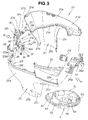
- Fig. 3 is an explosive perspective view of a lower cover of the outboard engine unit, which particularly shows an engine support member, front and rear brackets, etc.;
- Fig. 4 is an enlarged rear view of principal components of the outboard engine unit shown in Fig. 2, which particularly shows supporting, by the rear bracket, of the upper cover and left and right cover halves of the lower cover;
- Fig. 5 is a sectional view taken along line 5 - 5 of Fig. 4;
- Fig. 6 is a sectional view taken along line 6 - 6 of Fig. 5 ;
- Fig. 7 is a sectional view taken along line 7 - 7 of Fig. 5 ;
- Fig. 8 is an inner perspective view showing components provided on and adjacent to the inner surface of the rear bracket;
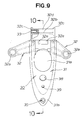
- Fig. 9 is a perspective view of the rear bracket with an auxiliary exhaust port and water pilot hole section removed;
- Fig. 10 is a sectional view taken along line 10 - 10 of Fig. 9 ;
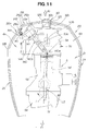
- Fig. 11 is a view showing the lower cover with the upper or engine cover removed for clarity and with a front section of the lower cover taken away; and
- Fig. 12 is an enlarged exploded view explanatory of principal elements shown in Fig. 11.
- Reference is now made to Figs. 1 to 3 inclusive, wherein Fig. 1 is a side view showing an outboard engine unit 1 in accordance with an embodiment of the present invention, in which inner mechanisms are indicated by broken lines, Fig. 2 is a rear view showing an example external appearance of the outboard engine unit 1, and Fig. 3 is an explosive perspective view of a lower cover (or lower cover assembly) 20 of the outboard engine unit 1, which particularly shows an engine support member, front and rear brackets, etc.
- In the figure, "Fr" represents a forward propelled direction of a boat to which is applied the outboard engine unit of the present invention, while "Rr" represents a rearward direction opposite from the forward propelled direction of the boat.
- Example external appearance of the outboard engine unit 1 is shown in the side view of Fig. 1 and rear view of Fig. 2. As shown, the outboard engine unit 1 includes an
engine cover 2 disposed in the uppermost position of the unit 1 and a lower cover (assembly) 20, and theseupper engine cover 2 andlower cover 20 together define anengine room 2i.Extension case 3 is provided under thelower cover 20, and agear case 4 disposed in the lowermost position of the unit 1 is joined to the lower end of theextension case 3. -
Engine 5 is accommodated and supported within an upper area of theengine room 2i, defined by the upper andlower covers lower cover 20. Theengine 5, which is in the form of a so-called vertical engine having a vertically orientedcrankshaft 5f, is a four-stroke engine with a plurality of cylinders (e.g., four cylinders in the instant embodiment) 5d that are disposed in a vertical arrangement. - The
engine 5 includes afront crankcase 5a,intermediate cylinder block 5b,rear cylinder head 5c, etc. Exhaust directed downward from thecylinder head 5c sequentially passes through an exhaust passageway in theengine mount case 6,exhaust pipe 7 downstream of theengine mount case 6, lower space in thelower cover 20,extension case 3 and then gearcase 4, so that it is ultimately discharged, as main exhaust, into the outside water through a center region of ascrew 14. - A plurality of
cylinders 5d are provided in thecylinder block 5b -in the instant embodiment, four horizontally-orientedcylinders 5d are disposed in a vertical arrangement-, and a plurality ofcombustion chambers 5e, openable and closeable with air intake and exhaust valves, are provided in thecylinder head 5c. - In a ride-side section of the
cylinder block 5b, there is accommodated anelectric component box 8 containing a circuit board for performing control of an engine ignition device and fuel injection device. Further, anintake silencer 9 is provided in front of theelectric component box 8 and extends along a side of thecrankcase 5a to a region in front of thecrankcase 5a, and a power generator (A.C. generator) 10 is disposed over theengine 5. - The
crankshaft 5f extending vertically through the interior of thecrankcase 5a of theengine 5 has its lower end portion connected to avertical drive shaft 12, and thedrive shaft 12 is connected at its lower end portion connected to agear transmission mechanism 13 accommodated in thegear case 4. Thegear transmission mechanism 13 transmits power, delivered from thedrive shaft 12, to a horizontal drivenshaft 13a provided in thegear case 4 in a front-end orientation. Rear end portion of the drivenshaft 13a projects rearwardly beyond the rear end of thegear case 4, and apropeller 14 is fixed to the rear end portion of the drivenshaft 13a. Thepropeller 14 is driven by the power of theengine 5, and switching is made, via a pair of dog clutches, between forward and reverse rotating directions of thepropeller 14 so that a forward or rearward propelling force can be obtained as desired. - Exhaust from the above-mentioned
main exhaust pipe 7 is directed downward as indicated by arrow (a) and then discharged to the outside through the center region of thescrew 14, and a portion of the exhaust is discharged to an outside region posterior to the outboard engine unit 1 as indicated by arrow (b). Exhaust passageway is provided in themount case 6 adjacent to themain exhaust pipe 7, and an auxiliary exhaust port orpipe 15 is provided adjacent to a downstream outlet of themain exhaust pipe 7. Theauxiliary exhaust pipe 15, which is formed of vinyl chloride and rubber, extends in the interior of theengine mount case 6 while being bent rearwardly and opens to the outside through a wall of thelower cover 20 to discharge the exhaust to an outside region posterior to the outboard engine unit 1 as indicated by arrow (b). - The lower cover (assembly) 20 has a water
pilot hole section 16 provided therein and having a hole formed therein to open to the outside, and the waterpilot hole section 16 discharges a portion of engine cooling water to the outside (downwardly from the lower cover 20) to permit a visual check as to whether the cooling water is appropriately flowing to an engine cooling section. -
Stern bracket 17 is supported on a front end portion of the outboard engine unit 1 via aswivel case 18.Reference numerals swivel case - Referring now to Fig. 2, the
upper cover 2, of the covers defining theengine room 2i, is formed integrally of resin, while the lower cover (assembly) 20 comprises left and right (i.e., port-side and starboard-side) cover members (or cover halves) integrally joined together in abutted relation to each other. The left and right cover members or halves) are each molded of resin. - The following paragraphs describe an example construction of the lower cover (assembly) 20, with primary reference to Fig. 3.
- The
lower cover 20 comprises left and right cover halves 21 and 25 each having a semi-oval shape as viewed in plan.Upper half sections lower half sections upper half sections lower half sections front portions upper half sections groove 21e of theleft cover half 21 is shown in Fig. 3) formed in their opposed inner surfaces and located in left-right symmetrical relation to each other (although not visible in the figure, the inner engaging groove of theright cover half 25 is formed in a position corresponding to the innerengaging groove 21e of the left cover half 21). When the left and right cover halves 21 and 25 are joined together in edge-to-edge abutted relation to each other, a sealing member 6g, which is provided on and along aperipheral flange portion 6f of theengine mount case 6, is fitted in the above-mentioned inner engaging grooves, to provide hermetic sealing between theengine mount case 6 and the lower cover (assembly) 20. - As further shown in Fig. 3, the
engine mount case 6 has ahole 6b through which a shift rod passing through a swivel shaft vertically extends, a hole 6a through which the drive shaft vertically extends, an engine-mountingflange 6c, an opening for returning oil to the oil pan 6e, ahole 6d through which themain exhaust pipe 7 vertically extends, etc. - Further, the
front portion 25b of theupper section 25a of theright cover half 25 is recessed downwardly, and aharness cover 22 is put on and integrally secured to the recessed part of thefront portion 25b to provide the completeright cover half 25. - In Fig. 3 the
front bracket 24 is positioned between the front ends of thefront portions front bracket 24 includes an upwardly-orientedsemicircular support arm 24a on its starboard side. Rubber-madecable bundle holder 23 is held or sandwiched between the upwardly-orientedsemicircular support arm 24a and a downwardly-oriented semicircular recessedportion 22a formed in a front end portion of theharness cover 22, to hold the cable bundle in such a manner that the cable bundle can be introduced or withdrawn to or from theengine room 2i. Thefront bracket 24 also includes anoperation arm 24b having a lock lever engageable, by operation of a handle, with ahook 2a (Fig. 1) provided on a front end portion of theupper cover 2. - The left and right cover halves 21 and 25 of the
lower cover 20 have rear upper abutting (joining) portions that are joined to therear bracket 30 as will be later detailed. - Fig. 4 is an enlarged rear view of principal (or relevant) components shown in Fig. 2, which particularly shows supporting, by the rear bracket, of the
upper cover 2 and left and right cover halves of thelower cover 20. Fig. 5 is a sectional view taken along the 5 - 5 line of Fig. 4, Fig. 6 is a sectional view taken along the 6 - 6 line of Fig. 5, and Fig. 7 is a sectional view taken along the 7 - 7 line of Fig. 5. Further, Fig. 8 is an inner perspective view showing components provided on and adjacent to the inner surface of therear bracket 30, Fig. 9 is a perspective view of therear bracket 30 with the auxiliary exhaust port and water pilot hole section removed therefrom, and Fig. 10 is a sectional view taken along the 10 - 10 line of Fig. 9. - The following paragraphs describe the
rear bracket 30 and how the rear portions of the left and right cover halves 21 and 25 of the lower cover (assembly) 20 are mounted and supported, with reference to the above-mentioned figures. - The
rear bracket 30 is provided for attaching the respective rear upper portions of the left and right cover halves 21 and 25 relative to the engine. Piping of theauxiliary exhaust port 15 and waterpilot hole section 16 are exposed on the inner (or reverse) surface of therear bracket 30. - The
rear bracket 30 is elongated in shape in a vertical direction of the outboard engine unit 1.Body 31 of therear bracket 30 is generally in the form of a plate having a gently-curved or downwardly-tapered lower half section, as viewed from the back (see Fig. 4); namely, therear bracket body 31 generally has a shield shape as viewed from the back. - The plate-shaped
body 31 of therear bracket 30 has a vertically-intermediate recessedportion 31a that bulges forward (i.e., inwardly) as clearly seen in Figs. 8 and 9. The recessedportion 31a constitutes a manual operation section of a later-described lock operation arm. Left and right mountingarm sections 32, projecting laterally away from each other and obliquely downward, are provided integrally with an upper inner surface portion of thebody 31 and exposed toward a middle region of the rear surface of thelower cover 20; the left and right mountingarm sections 32 together form a downward dogleg configuration. The mountingarm sections 32 have respective mountingholes 32a at their respective distal ends and are formed, as a whole, as a ribreinforced structure of a channel-like sectional shape. -
Intermediate section 32b that is formed as a base of the left and right mountingarm sections 32 has left and right vertically-projectingportions 32c formed integrally therewith at opposite ends thereof. Cross holdingsection 32d extends between the projectingportions 32c, and mountingnuts 33 are embedded in opposite end portions of theholding section 32d.Hinge support portions 32e of the lock operation arm are provided, on an upper outer surface area of the plate-shapedbody 31, for supporting a pivotal base of theoperation arm 40. -
Grooves 34 recessed inwardly in the width direction of the plate-shapedbody 31 are provided in and along opposite side edges of thebody 31, and the width of the recessedgrooves 34 is slightly greater than the thickness of the cover halves 21 and 25. - Further, the plate-shaped
body 31 has abolt hole 35 formed in itslower end portion 31b, and a mountingboss portion 36 is provided integrally on an inner surface area of thebody 31 corresponding in position to thebolt hole 35.Nut 37 is embedded in and fixed, by welding or otherwise, to the inner surface of the mountingboss portion 36. - The above-mentioned
operation arm 40,operation lever 40b andshaft 40c, which are all provided on therear bracket 30, together constitute a lock device of theengine cover 2 in conjunction with alocking hook 2b on theengine cover 2. -
Hole 38 for mounting the auxiliary exhaust port orpipe 15 is formed in the plate-shapedbody 31 beneath the above-mentioned recessedportion 31a, and ahole 39 for mounting the waterpilot hole section 16 is formed beneath the mountinghole 38. The auxiliary-exhaust-pipe mounting hole 38 has a greater diameter than the water-pilot-section mounting hole 39. As seen from Fig. 4, the auxiliary exhaust port orpipe 15 and waterpilot hole section 16 open to the rear surface of thebracket 30. - The
auxiliary exhaust port 15 has anupstream portion 15a located adjacent to the inner surface of the plate-shapedbody 31, and an upstream-end opening portion having aflange 15b. Theflange 15b abuts against an area of the body's inner surface around the auxiliary-exhaust-pipe mounting hole 38. Further, atube 16a of the waterpilot hole section 16 is indicated by broken lines in Fig. 4 and projects forwardly or inwardly beyond the inner surface of the plate-shapedbody 31, and anozzle portion 16b of the waterpilot hole section 16 is fitted in thehole 39, as seen from Fig. 8. - Now, with reference to Figs. 4 - 7, a description will be given about how the
rear bracket 30 and theengine 5 are mounted and therear bracket 30 is connected with the cover halves 21 and 25. - As shown in Fig. 4, mounting
seat portions 5i, projecting laterally outwardly away from each other, are provided on left- and right-side regions of arear surface 5k of thecylinder head 5c, and the left and right mountingarm sections 32 projecting laterally outwardly from the plate-shapedbody 31 are fixed to the mountingseat portions 5i by means ofbolts 42, corresponding in size to the mountingholes 32a, viarespective collars 41. - In the aforementioned manner, the
rear bracket 30 is attached to (i.e., mounted and supported on) the rear surface of theengine 5. Therear bracket 30 may be attached the rear surface of theengine mount case 6 rather than to theengine 5. - Vertically-elongated
engaging sections edges bosses holes sections bosses - The abuttingly-joining
edges sections grooves 34 formed in the left and right side edges of the plate-shapedbody 31 of the rear bracket 30 (see Fig. 7). - The mounting
bosses sections portions 32c formed on an upper surface region of therear bracket 30. Then,bolts 43 are inserted in mountingholes bosses bosses bosses rear bracket 30, so that upper end portions of the left and right cover halves 21 and 25 are attached to (i.e., mounted and supported on) thebracket 30. - Decorative bolt is passed through a mounting hole formed in a lower end portion of the
bracket body 31, and mountingholes 31k formed near the lower ends of the engagingsections hole 31k of theleft cover half 21 is visible in Fig. 3) are overlapped with each other on the nut 37 (see Fig. 3) and secured together by means of thenut 37 as will be later described. - In the instant embodiment constructed in the above-described manner, only the
body 31 of thebracket 30 is exposed on the rear surfaces of the upper cover andlower cover 20, and elements for mounting the various components to theengine 5 and left and right cover halves 21 and 25 are hidden by the covers. - Joining
seat portions sections seat portions 121d is formed as a recessed portion bent inwardly into the engine room, and the other of the joiningseat portions 125d has a wall thickness corresponding to the recessed depth of the one joiningseat portion 121d. These joiningseat portions - As shown in (a) of Fig. 6, the joining
seat portions hole portions portion 44a of a steppedbolt 44 and having ahole bolt 44 is tightly passed through the through-holes - The joining
seat portions hole portions - The
bolt 44 is inserted through thehole 39 formed in a lower end portion of the plate-shapedbody 31 of thebracket 30 so that the bolt's threadedportion 44a is loosely passed through theholes seat portions nut 37 fixed, by welding or otherwise, to the mountingboss portion 36 fixedly provided on an inner surface area of thebody 31. Thenut 37 functions as a fixed threaded member. - As the screwing, into the nut or fixed threaded
member 37, of thebolt 44 progresses, the greater-diameter portion 44b of thebolt 44 reaches thetapering hole portion 121e of the inner joiningseat portion 121d by way of thetapering hole portion 125e of the outer joiningseat portion 125d, so that the twoseat portions sections bracket 30 with theholes seat portions - As shown in Fig. 5, the locking
hook 2b is provided on a lower rear surface area of theupper cover 2 in vertically opposed relation to theoperation arm 40. Thelock lever 40a is caused to engage thelocking hook 2b through pivoting, about theshaft 40c, of theoperation lever 40b of theoperation arm 40, to thereby lock the back of theengine cover 2 in a closed position, i.e. fix theupper cover 2 to thelower cover 20 in a closed position. - In Fig. 5, the locking
hook 2b is fastened to the back of theengine cover 2 by means ofrivets 2c. In Figs. 4 and 5,reference numeral 6h represents an auxiliary exhaust passageway provided in theengine mount case 6 and communicating at one end with adownstreammost portion 15c of theauxiliary exhaust port 15, to thereby allow a portion of the engine exhaust to flow to theauxiliary exhaust port 15. - Because the
auxiliary exhaust port 15 and waterpilot hole section 16 are provided in therear bracket 30, supporting thelower cover 20, as described above, the instant embodiment can eliminate the need to detach the piping of theauxiliary exhaust port 15, waterpilot hole section 16, sealing members, etc. from thelower cover 20 when thelower cover 20 is to be detached for desired work. Thus, in the instant embodiment, no operation for re-attaching the piping of theauxiliary exhaust port 15, waterpilot hole section 16, sealing members, etc. is required after the desired work. Therefore, even in the case where theauxiliary exhaust port 15, waterpilot hole section 16 are provided, it is only necessary to perform operation for detaching thelower cover 20 for desired work. - Further, in the instant embodiment, the left and right cover halves 21, 25 of the
lower cover 20 are mounted and supported on therear bracket 30 independently of each other. Thus, even when one of the left and right cover halves 21 or 25 is detached from thebracket 30, the other of the left and right cover halves 25 or 21 is still kept attached to therear bracket 30, which can facilitate the detachment of the one cover half and subsequent re-attachment of the one cover half. - In Figs. 1, 2 and 4,
reference numeral 26 represents an ignition plug maintenance lid provided on an uppermost region of the rear surface of one of the left and right lower cover halves (rightlower cover half 25 in the above-described embodiment): By detaching the ignitionplug maintenance lid 26, the ignition plug can be exposed to the engine combustion chamber defined in the cylinder head of any one of the cylinders disposed in a vertical arrangement, so that checking, replacing operation, etc. of the plug can be performed; at that time, theengine cover 2 located over thelower cover 20 need not be detached. - Further, when checking etc. of the ignition plugs, disposed in a vertical arrangement in correspondence with the cylinders, is to be performed with the
engine cover 2 removed, it would be difficult to check some of the plugs, located in a lower position in the vertical arrangement, due to the presence of the lower cover. However, detaching thelid 26 can facilitate such plug checking. - Fig. 11 is a view showing the lower cover (assembly) 20 with the upper or
engine cover 2 removed and a front section of thelower cover 20 taken away for convenience of illustration, and Fig. 12 is an enlarged exploded view explanatory of principal elements shown in Fig. 11. - The
crankcase 5a of theengine 5 is located in a front area of theengine room 2i, thecylinder block 5b in a middle area f theengine room 2i, and thecylinder head 5c and cylinder head cover (not shown) are located in a rear area of theengine room 2i. - Centerline L2 of the
cylinder 5d in thecylinder block 5b, extending in the front-rear direction of the outboard engine unit 1, is displaced or offset from a centerline L1 of the unit 1, extending centrally across the width of the unit 1, by a distance D toward the left or port side of the unit 1 (right side in Fig. 11). - As seen in Fig. 11, the centerline L1 of the outboard engine unit 1 corresponds with the center of the
crankshaft 5f and the center of thedrive shaft 12, and it also agrees with a centerline of theengine room 2i centrally across the width of theengine room 2i. Thecrankshaft 5f rotates in a direction arrowed in Fig. 11. - Thus, the
engine 5, including thecylinder head 5c, is offset toward the left or port side of the unit 1 (right side in Fig. 11), so that a right-side (i.e., starboard-side) space (left-side space in Fig. 11) 4a is greater than a left-side (i.e., port-side) space (right-side space in Fig. 11) 4b. -
Hole 53c for mounting therein theignition plug 140, communicating with thecombustion chamber 5e, is formed in thecylinder head 5c to extend obliquely rearwardly in thegreater space 4a, and theignition plug 140 is passed through thehole 53c. - The
ignition plug 140 includes anelectrode section 140a provided at its distal end and located within thecombustion chamber 5e, and a shaft shapedbody 140b having an insulating material and extending obliquely upward through the mountinghole 53c. Terminal provided at the top of the shaft-shapedbody 140b is connected, via a high-tension cord, to a terminal provided within a cap-shapedhead section 141, and it is supplied with electric power from the terminal within thehead section 141. - The plug's
head section 141 projecting outward from thecylinder head 5c is located in an L-shapedspace 53e defined between anexhaust passage portion 53d in thecylinder head 5c and the ceiling of thecylinder head 5c (i.e., surface abutted against the cylinder head cover). Thehead section 141 faces, or is oriented toward, a starboard- or right-side (left-side in the figure)rear surface 20a, but it is never oriented toward the rear joint section where the left and right cover halves 21 and 25 are joined together via therear bracket 23. Axis line L3 of theignition plug 140 and mountinghole 53c are oriented toward a starboard- or right-side rear region displaced from therear bracket 31. - Recessed
section 142 is formed in an upper region of the rear surface 135 (Fig. 4) of one of the lower cover halves which is located on an extension of the axis line L3 of theignition plug 140, i.e. the right or starboard-side cover half (left one in the figure) 25. - The recessed
section 142 is in the form of an upwardly-opening recess provided to correspond to the above-mentioned axis line L3 of theignition plug 140, i.e. a direction in which theignition plug 140 is to be pulled out from thehole 53c and hence the cover half 25 (i.e., "pulled-out direction" of the plug 140). As seen in Fig. 4, the recessedsection 142 in the instant embodiment has a substantially-linearouter edge 142a, a gently-curved bottom edge 142b, and an inner side edge 142c curved upwardly and inwardly. - The recessed
section 142 opens upwardly, as noted above, with its left and right upper edges merging with a rear upper edge of thecover half 25, and this recessedsection 142 is openable and closeable with the above-mentionedlid 26 corresponding in shape to the recessedsection 142. - As seen in Fig. 12, the
lid 26 includes a plate-shapedbody 26a corresponding in shape to the recessedsection 142, a reinforcingrib 26b formed on and along the periphery of its inner surface, and anarm portion 26c. Thearm portion 26c has a mountinghole 26d formed in its one end region. - Supporting
stay 144 is provided on the inner surface of theright cover half 25 adjacent to the outer edge of the recessedsection 142, and the supportingstay 144 has a mountingscrew hole 144a.Bolt 45 is passed through the mountinghole 26d of thelid 26 into threaded engagement with the mountingscrew hole 144a, to thereby fix thelid 26 to the recessedsection 142 in a closed position. In Figs. 11 and 12,reference numeral 53b represents a camshaft. - The
lid 26 can be detached from the recessedsection 142 by removing the upper orengine cover 2 andbolt 45, as illustrated in Fig. 12. - The
ignition plug 140, which has its axis line L3 orientated toward the recessedsection 142, can be pulled out from the recessedsection 142 as indicated by arrow (c). Because thespace 4a is relatively great, not only theignition plug 140 can be inserted to and pulled out from thehole 53c with ease, but also theexhaust passage portion 53d of thecylinder head 5c etc. can be installed in position with ease. - Further, because the left and right cover halves 21 and 25 are attached at their respective upper portions to the
rear bracket 30 and because thebracket 30 is not located in the direction where theignition plug 140 is to be inserted to and pulled out from thehole 53c (i.e., the inserted/pulled-out direction of theplug 140 does not correspond to the location of the rear bracket 30), the insertion/removal of theplug 140 will never be interfered with by the presence of therear bracket 30. - The above-described lower-cover mounting construction is suitably applicable to lower covers of outboard engine units. Further, the above-described positioning and orientation of the ignition plug, the recessed section for maintenance of the plug and the lid for opening/closing the recessed section are suitably applicable to outboard engine units.
- In an outboard engine unit, a cover assembly (20), defining a lower half section of an engine room (2i), is composed of left and right cover members (21,25) each formed of resin, and a bracket (30) is fixed to a rear portion of the engine (5) or engine support structure (6). The left and right cover members are fixed at their respective rear portions to the bracket (30). Centerline (L2) of an engine cylinder (5d) is offset from a centerline (L1) of the engine room toward one of left and right sides of the unit, and an ignition plug (140) is provided on the other side opposite from the one side toward which the engine cylinder centerline (L2) is offset.
Claims (16)
- An outboard engine unit comprising:a cover assembly (20) defining a lower half of an engine room (2i) having an engine (5) accommodated therein, said cover assembly comprising left and right cover members (21,25) each formed of resin; anda bracket (30) fixed to a rear portion of the engine (5) or engine support structure (6), said left and right cover members being fixed at respective rear portions thereof to said bracket.
- The outboard engine unit of claim 1, wherein said bracket (30) has grooves (34), formed in opposite side edges thereof, for engaging predetermined joining edges of said left and right cover members (21,25).
- The outboard engine unit of claim 1, wherein said left and right cover members (21,25) have respective joining portions (121d, 125d) overlapping with each other, each of the joining portions having a tapering hole (121e, 125e),
said left and right cover members are fastened together by a bolt (44) screwed through respective ones of the tapering holes, initially displaced from each other in a left-right direction of said outboard engine unit, to a predetermined fixed threaded portion (37) to tighten the respective joining portions against said bracket and thereby press said left and right cover members toward each other. - The outboard engine unit of claim 1, wherein said bracket has a lock device (40,40b,40c) provided thereon for locking an engine cover (2).
- An outboard engine unit comprising :a cover assembly (20) defining a lower half of an engine room (2i) having an engine (5) accommodated therein, said cover assembly comprising left and right cover members (21,25) each formed of resin ; anda bracket (30) fixed to a rear portion of the engine (5) or engine support structure (6), said bracket having an auxiliary exhaust port (15) provided therein for discharging a portion of exhaust of the engine to outside of the engine room.
- The outboard engine unit of claim 5, wherein said left and right cover members are connected at respective rear portions thereof to said bracket.
- The outboard engine unit of claim 6, wherein said left and right cover members (21,25) have respective joining portions (121d, 125d) overlapping with each other, each of the joining portions having a tapering hole (121e, 125e),
said left and right cover members are fastened together by a bolt (44) screwed through the tapering holes, initially displaced from each other in a left-right direction of said outboard engine unit, to a predetermined fixed threaded portion (37) to tighten the respective joining portions against said bracket and thereby press said left and right cover members toward each other. - The outboard engine unit of claim 6, wherein said bracket (30) has a lock device (40,40b,40c) provided thereon for locking an engine cover (2).
- An outboard engine unit comprising:a cover assembly (20) defining a lower half of an engine room (2i) having an engine accommodated therein, said cover assembly comprising left and right cover members each formed of resin; anda bracket (30) fixed to a rear portion of the engine (5) or engine support structure (6), said bracket having a water pilot hole (16) provided therein for discharging a portion of cooling water of the engine to outside of the engine room.
- The outboard engine unit of claim 9, wherein said left and right cover members are connected at respective rear portions thereof to said bracket.
- The outboard engine unit of claim 10, wherein said left and right cover members (21,25) have respective joining portions (121d.125d) overlapping with each other, each of the joining portions having a tapering hole (121e,125e),
said left and right cover members are fastened together by a bolt (44) screwed through respective ones of the tapering holes, initially displaced from each other in a left-right direction of said outboard engine unit, to a predetermined fixed threaded portion (37) to tighten the respective joining portions against said bracket and thereby press said left and right cover members toward each other. - The outboard engine unit of claim 10, wherein said bracket has a lock device provided thereon for locking an engine cover.
- An outboard engine unit comprising:an engine room (2i) having an engine (5) accommodated therein, a centerline (L2) of an engine cylinder (5d) being offset from a centerline (L1) of said engine room toward one of left and right sides of said outboard engine unit; andan ignition plug (140) provided on other of the left and right sides, opposite from the one side toward which the centerline (L2) of the engine cylinder is offset.
- The outboard engine unit of claim 13, wherein said engine room (2i) is defined by a lower cover (20) and an engine cover (2) joined to said lower cover from above, and said lower cover has a recessed section (42) formed in a portion thereof coinciding with a pulled-out direction of said ignition plug, said recessed section being openable/closeable by a lid (26).
- The outboard engine unit of claim 14, wherein said lower cover (20) comprises left and right cover members (21,25) each formed of resin, and one of the left and right cover members has said recessed section (142) formed therein and the lid (26) provided thereon.
- The outboard engine unit of claim 15, which further comprises a bracket (30) fixed to a rear portion of the engine (5) or engine support structure (6), and
wherein the left and right cover members of said lower cover are fixed to said bracket, and said ignition plug (140) is disposed in such a manner that the pulled-out direction does not coincide with a location of said bracket (30).
Applications Claiming Priority (2)
| Application Number | Priority Date | Filing Date | Title |
|---|---|---|---|
| JP2006127667A JP4721438B2 (en) | 2006-05-01 | 2006-05-01 | Outboard motor |
| JP2006127504A JP4833723B2 (en) | 2006-05-01 | 2006-05-01 | Outboard motor |
Publications (3)
| Publication Number | Publication Date |
|---|---|
| EP1852589A2 true EP1852589A2 (en) | 2007-11-07 |
| EP1852589A3 EP1852589A3 (en) | 2008-09-10 |
| EP1852589B1 EP1852589B1 (en) | 2012-01-11 |
Family
ID=38016963
Family Applications (1)
| Application Number | Title | Priority Date | Filing Date |
|---|---|---|---|
| EP07008335A Active EP1852589B1 (en) | 2006-05-01 | 2007-04-24 | Outboard engine unit |
Country Status (3)
| Country | Link |
|---|---|
| US (1) | US7621791B2 (en) |
| EP (1) | EP1852589B1 (en) |
| CA (1) | CA2584386C (en) |
Cited By (2)
| Publication number | Priority date | Publication date | Assignee | Title |
|---|---|---|---|---|
| US8684777B2 (en) | 2007-04-04 | 2014-04-01 | Dolprop Industries Ab | Propulsion device for propelling a floating watercraft, a conversion kit for replacing a propeller where the kit comprises such a propulsion device, a watercraft comprising such a propulsion device and a method for increasing the efficiency by using such a conversion kit |
| EP3967593A1 (en) * | 2020-09-11 | 2022-03-16 | Yamaha Hatsudoki Kabushiki Kaisha | Outboard motor |
Families Citing this family (13)
| Publication number | Priority date | Publication date | Assignee | Title |
|---|---|---|---|---|
| JP5134992B2 (en) * | 2008-02-01 | 2013-01-30 | 本田技研工業株式会社 | Outboard motor |
| US8858280B1 (en) | 2010-10-29 | 2014-10-14 | Brp Us Inc. | Marine engine rigging system |
| US9073616B1 (en) | 2010-10-29 | 2015-07-07 | Brp Us Inc. | Marine engine cowling |
| USD666633S1 (en) * | 2011-02-10 | 2012-09-04 | Suzuki Motor Corporation | Outboard motor |
| US8834216B1 (en) | 2013-01-31 | 2014-09-16 | Brp Us Inc. | Water deflector for a marine outboard engine |
| US9580943B1 (en) * | 2015-09-30 | 2017-02-28 | Brunswick Corporation | Cowls and latching devices for outboard marine engines |
| US9580947B1 (en) * | 2015-09-30 | 2017-02-28 | Brunswick Corporation | Cowls and latching assemblies for cowls on outboard marine propulsion devices |
| JP6580260B2 (en) * | 2016-05-25 | 2019-09-25 | 本田技研工業株式会社 | Heat source cover |
| JP6815272B2 (en) * | 2017-05-12 | 2021-01-20 | ヤマハ発動機株式会社 | Seal structure for outboard motors and split engine covers used for them |
| US10161168B1 (en) | 2017-12-05 | 2018-12-25 | Brunswick Corporation | Cowlings and latching assemblies for cowlings on marine drives |
| US10718142B1 (en) | 2018-01-10 | 2020-07-21 | Brunswick Corporation | Carrying trays and methods for transporting and installing latching assemblies on cowlings for marine drives |
| US11046409B2 (en) | 2018-12-21 | 2021-06-29 | Brp Us Inc. | Marine outboard engine cowling |
| JP2022098622A (en) * | 2020-12-22 | 2022-07-04 | ヤマハ発動機株式会社 | Outboard engine |
Citations (1)
| Publication number | Priority date | Publication date | Assignee | Title |
|---|---|---|---|---|
| EP1116865A2 (en) | 2000-01-17 | 2001-07-18 | Honda Giken Kogyo Kabushiki Kaisha | Structure of mounting of exhaust gas sampling pipe in outboard engine system |
Family Cites Families (17)
| Publication number | Priority date | Publication date | Assignee | Title |
|---|---|---|---|---|
| US4348194A (en) * | 1980-07-01 | 1982-09-07 | Brunswick Corporation | Cowl for an outboard motor |
| JPS6038293A (en) * | 1983-08-10 | 1985-02-27 | Honda Motor Co Ltd | Outboard engine |
| US4708673A (en) * | 1985-07-03 | 1987-11-24 | Outboard Marine Corporation | Outboard motor cowl assembly |
| US5055074A (en) * | 1990-05-18 | 1991-10-08 | Outboard Marine Corporation | Molded control panel for outboard motor |
| US5069643A (en) * | 1990-05-18 | 1991-12-03 | Outboard Marine Corporation | Molded lower motor cover |
| US5560247A (en) * | 1992-09-16 | 1996-10-01 | Honda Giken Kogyo Kabushiki Kaisha | Exhaust gas sampling device for outboard motor |
| US5360358A (en) * | 1993-05-21 | 1994-11-01 | Outboard Marine Corporation | Hidden lower motor cover attachment means |
| US5487687A (en) * | 1994-07-18 | 1996-01-30 | Brunswick Corporation | Midsection and cowl assembly for an outboard marine drive |
| JP2001115817A (en) | 1999-10-14 | 2001-04-24 | Sanshin Ind Co Ltd | Breather chamber structure for outboard motor |
| JP2001199393A (en) | 2000-01-17 | 2001-07-24 | Honda Motor Co Ltd | Supporting structure of under cover in outboard engine |
| DE60226564D1 (en) * | 2001-11-29 | 2008-06-26 | Yamaha Marine K K | Outboard motor |
| US7210973B2 (en) * | 2002-04-11 | 2007-05-01 | Brp Us Inc. | Outboard engine cowling |
| CA2434998C (en) * | 2002-07-18 | 2010-05-25 | Honda Giken Kogyo Kabushiki Kaisha | Cover joining structure for outboard engine unit |
| CA2434563C (en) * | 2002-07-18 | 2007-03-27 | Honda Giken Kogyo Kabushiki Kaisha | Outboard motor |
| JP2004338463A (en) | 2003-05-13 | 2004-12-02 | Honda Motor Co Ltd | Cover structure of outboard motor |
| JP4428145B2 (en) * | 2004-05-31 | 2010-03-10 | スズキ株式会社 | Outboard motor intake structure |
| JP4583332B2 (en) * | 2006-04-28 | 2010-11-17 | 本田技研工業株式会社 | Outboard motor equipped with an internal combustion engine with an electrical box |
-
2007
- 2007-04-11 CA CA2584386A patent/CA2584386C/en not_active Expired - Fee Related
- 2007-04-19 US US11/785,632 patent/US7621791B2/en active Active
- 2007-04-24 EP EP07008335A patent/EP1852589B1/en active Active
Patent Citations (1)
| Publication number | Priority date | Publication date | Assignee | Title |
|---|---|---|---|---|
| EP1116865A2 (en) | 2000-01-17 | 2001-07-18 | Honda Giken Kogyo Kabushiki Kaisha | Structure of mounting of exhaust gas sampling pipe in outboard engine system |
Cited By (2)
| Publication number | Priority date | Publication date | Assignee | Title |
|---|---|---|---|---|
| US8684777B2 (en) | 2007-04-04 | 2014-04-01 | Dolprop Industries Ab | Propulsion device for propelling a floating watercraft, a conversion kit for replacing a propeller where the kit comprises such a propulsion device, a watercraft comprising such a propulsion device and a method for increasing the efficiency by using such a conversion kit |
| EP3967593A1 (en) * | 2020-09-11 | 2022-03-16 | Yamaha Hatsudoki Kabushiki Kaisha | Outboard motor |
Also Published As
| Publication number | Publication date |
|---|---|
| CA2584386C (en) | 2013-11-19 |
| EP1852589B1 (en) | 2012-01-11 |
| CA2584386A1 (en) | 2007-11-01 |
| US7621791B2 (en) | 2009-11-24 |
| EP1852589A3 (en) | 2008-09-10 |
| US20070254539A1 (en) | 2007-11-01 |
Similar Documents
| Publication | Publication Date | Title |
|---|---|---|
| CA2584386C (en) | Outboard engine unit | |
| US7013874B2 (en) | Engine fuel injection apparatus | |
| US9073616B1 (en) | Marine engine cowling | |
| JP4719615B2 (en) | Cover structure of outboard motor. | |
| JP4672620B2 (en) | Cover structure of internal combustion engine | |
| US6846211B2 (en) | Cover joining structure for outboard engine unit | |
| US6364724B1 (en) | Grommet assembly for outboard motor | |
| CN101066703B (en) | Outboard engine unit | |
| US7513811B2 (en) | Idle exhaust structure for outboard motor | |
| JP4720482B2 (en) | Motorcycle frame cover | |
| JP4721438B2 (en) | Outboard motor | |
| US20040014377A1 (en) | Outboard motor | |
| CA2128383C (en) | Outboard engine structure | |
| EP0588349B1 (en) | Exhaust gas sampling device for outboard motor | |
| US6790111B2 (en) | Outboard motor | |
| US20080264666A1 (en) | Electrical component box for water vehicle | |
| JP2008092798A (en) | Electric drive unit | |
| JP2009281237A (en) | Intake structure for straddle type vehicle | |
| JP4195224B2 (en) | Parts for ship propulsion equipment | |
| JP2001239842A (en) | Engine mounting device | |
| JP2003328755A (en) | Air bleeding device for cooling water of car engine | |
| JP4706329B2 (en) | Outboard motor cooling water passage cleaning device | |
| US7540272B2 (en) | Fuel supply device | |
| JPH11291988A (en) | Electric drive device | |
| JPH0357297B2 (en) |
Legal Events
| Date | Code | Title | Description |
|---|---|---|---|
| PUAI | Public reference made under article 153(3) epc to a published international application that has entered the european phase |
Free format text: ORIGINAL CODE: 0009012 |
|
| 17P | Request for examination filed |
Effective date: 20070424 |
|
| AK | Designated contracting states |
Kind code of ref document: A2 Designated state(s): AT BE BG CH CY CZ DE DK EE ES FI FR GB GR HU IE IS IT LI LT LU LV MC MT NL PL PT RO SE SI SK TR |
|
| AX | Request for extension of the european patent |
Extension state: AL BA HR MK YU |
|
| PUAL | Search report despatched |
Free format text: ORIGINAL CODE: 0009013 |
|
| AK | Designated contracting states |
Kind code of ref document: A3 Designated state(s): AT BE BG CH CY CZ DE DK EE ES FI FR GB GR HU IE IS IT LI LT LU LV MC MT NL PL PT RO SE SI SK TR |
|
| AX | Request for extension of the european patent |
Extension state: AL BA HR MK RS |
|
| 17Q | First examination report despatched |
Effective date: 20081107 |
|
| AKX | Designation fees paid |
Designated state(s): DE FR SE |
|
| GRAP | Despatch of communication of intention to grant a patent |
Free format text: ORIGINAL CODE: EPIDOSNIGR1 |
|
| GRAS | Grant fee paid |
Free format text: ORIGINAL CODE: EPIDOSNIGR3 |
|
| GRAA | (expected) grant |
Free format text: ORIGINAL CODE: 0009210 |
|
| RAP1 | Party data changed (applicant data changed or rights of an application transferred) |
Owner name: HONDA MOTOR CO., LTD. |
|
| AK | Designated contracting states |
Kind code of ref document: B1 Designated state(s): DE FR SE |
|
| REG | Reference to a national code |
Ref country code: DE Ref legal event code: R096 Ref document number: 602007019906 Country of ref document: DE Effective date: 20120315 |
|
| REG | Reference to a national code |
Ref country code: SE Ref legal event code: TRGR |
|
| PLBE | No opposition filed within time limit |
Free format text: ORIGINAL CODE: 0009261 |
|
| STAA | Information on the status of an ep patent application or granted ep patent |
Free format text: STATUS: NO OPPOSITION FILED WITHIN TIME LIMIT |
|
| 26N | No opposition filed |
Effective date: 20121012 |
|
| REG | Reference to a national code |
Ref country code: DE Ref legal event code: R097 Ref document number: 602007019906 Country of ref document: DE Effective date: 20121012 |
|
| PGFP | Annual fee paid to national office [announced via postgrant information from national office to epo] |
Ref country code: SE Payment date: 20140411 Year of fee payment: 8 |
|
| REG | Reference to a national code |
Ref country code: SE Ref legal event code: EUG |
|
| PG25 | Lapsed in a contracting state [announced via postgrant information from national office to epo] |
Ref country code: SE Free format text: LAPSE BECAUSE OF NON-PAYMENT OF DUE FEES Effective date: 20150425 |
|
| REG | Reference to a national code |
Ref country code: FR Ref legal event code: PLFP Year of fee payment: 10 |
|
| REG | Reference to a national code |
Ref country code: FR Ref legal event code: PLFP Year of fee payment: 11 |
|
| REG | Reference to a national code |
Ref country code: FR Ref legal event code: PLFP Year of fee payment: 12 |
|
| REG | Reference to a national code |
Ref country code: DE Ref legal event code: R084 Ref document number: 602007019906 Country of ref document: DE |
|
| PGFP | Annual fee paid to national office [announced via postgrant information from national office to epo] |
Ref country code: FR Payment date: 20210310 Year of fee payment: 15 |
|
| PG25 | Lapsed in a contracting state [announced via postgrant information from national office to epo] |
Ref country code: FR Free format text: LAPSE BECAUSE OF NON-PAYMENT OF DUE FEES Effective date: 20220430 |
|
| PGFP | Annual fee paid to national office [announced via postgrant information from national office to epo] |
Ref country code: DE Payment date: 20230228 Year of fee payment: 17 |