EP1865261A2 - Inlet flow conditioner for gas turbine engine fuel nozzle - Google Patents
Inlet flow conditioner for gas turbine engine fuel nozzle Download PDFInfo
- Publication number
- EP1865261A2 EP1865261A2 EP07108515A EP07108515A EP1865261A2 EP 1865261 A2 EP1865261 A2 EP 1865261A2 EP 07108515 A EP07108515 A EP 07108515A EP 07108515 A EP07108515 A EP 07108515A EP 1865261 A2 EP1865261 A2 EP 1865261A2
- Authority
- EP
- European Patent Office
- Prior art keywords
- ifc
- wall
- chamber
- perforations
- air
- Prior art date
- Legal status (The legal status is an assumption and is not a legal conclusion. Google has not performed a legal analysis and makes no representation as to the accuracy of the status listed.)
- Withdrawn
Links
Images


Classifications
-
- F—MECHANICAL ENGINEERING; LIGHTING; HEATING; WEAPONS; BLASTING
- F23—COMBUSTION APPARATUS; COMBUSTION PROCESSES
- F23R—GENERATING COMBUSTION PRODUCTS OF HIGH PRESSURE OR HIGH VELOCITY, e.g. GAS-TURBINE COMBUSTION CHAMBERS
- F23R3/00—Continuous combustion chambers using liquid or gaseous fuel
- F23R3/28—Continuous combustion chambers using liquid or gaseous fuel characterised by the fuel supply
- F23R3/286—Continuous combustion chambers using liquid or gaseous fuel characterised by the fuel supply having fuel-air premixing devices
-
- F—MECHANICAL ENGINEERING; LIGHTING; HEATING; WEAPONS; BLASTING
- F23—COMBUSTION APPARATUS; COMBUSTION PROCESSES
- F23R—GENERATING COMBUSTION PRODUCTS OF HIGH PRESSURE OR HIGH VELOCITY, e.g. GAS-TURBINE COMBUSTION CHAMBERS
- F23R3/00—Continuous combustion chambers using liquid or gaseous fuel
- F23R3/02—Continuous combustion chambers using liquid or gaseous fuel characterised by the air-flow or gas-flow configuration
- F23R3/26—Controlling the air flow
Landscapes
- Engineering & Computer Science (AREA)
- Chemical & Material Sciences (AREA)
- Combustion & Propulsion (AREA)
- Mechanical Engineering (AREA)
- General Engineering & Computer Science (AREA)
- Turbine Rotor Nozzle Sealing (AREA)
Abstract
Description
- This invention relates generally to rotary machines and more particularly, to gas turbine engines and methods of operation.
- At least some gas turbine engines ignite a fuel-air mixture in a combustor and generate a combustion gas stream that is channeled to a turbine via a hot gas path. Compressed air is channeled to the combustor by a compressor. Combustor assemblies typically have fuel nozzles that facilitate fuel and air delivery to a combustion region of the combustor. The turbine converts the thermal energy of the combustion gas stream to mechanical energy that rotates a turbine shaft. The output of the turbine may be used to power a machine, for example, an electric generator or a pump.
- Some known fuel nozzles include at least one inlet flow conditioner (IFC). Typically, an IFC includes a plurality of perforations and is configured to channel air from the compressor into a portion of the fuel nozzle to facilitate mixing of fuel and air. One known engine channels air into the fuel nozzle to facilitate mitigating air turbulence and to produce a radial and circumferential air flow velocity profile that is substantially uniform within the IFC. Some known IFCs include at least one flow vane that facilitates the generation of a non-uniform radial air flow velocity profile within some portions of the IFC.
- In one aspect according to the present invention, a method of operating a gas turbine engine is provided. The method includes providing an inlet flow conditioner (IFC) having an annular chamber defined therein by at least one wall that is formed with a plurality of perforations extending therethrough. The plurality of perforations are spaced in at least two axially-spaced rows that extend substantially circumferentially about the wall. The method also includes channeling a fluid into the IFC and discharging the fluid from the IFC with a substantially uniform flow profile.
- In another aspect, an inlet flow conditioner (IFC) is provided. The IFC includes an annular chamber at least partially defined therein by a first wall that includes a plurality of perforations extending therethrough. The plurality of perforations are spaced equidistantly circumferentially from each other and are configured to channel a fluid such that a substantially uniform flow profile of the fluid is discharged from the at least one chamber.
- In a further aspect, a gas turbine engine is provided. The engine includes a compressor and a combustor in flow communication with the compressor. The combustor includes a fuel nozzle assembly that includes an inlet flow conditioner (IFC). The IFC includes an annular IFC chamber at least partially defined therein by a first wall that includes a plurality of perforations extending therethrough. The plurality of perforations are spaced equidistantly circumferentially from each other and are configured to channel a fluid such that a substantially uniform flow profile discharges from the annular IFC chamber.
- Various aspects and embodiments of the present invention will now be described in connection with the accompanying drawings, in which:
- Figure 1 is a schematic view of an exemplary gas turbine engine;
- Figure 2 is a cross-sectional schematic view of an exemplary combustor that may be used with the gas turbine engine shown in Figure 1;
- Figure 3 is a cross-sectional schematic view of an exemplary fuel nozzle assembly that may be used with the combustor shown in Figure 2;
- Figure 4 is a fragmentary view of an exemplary inlet flow conditioner (IFC) that may be used with the fuel nozzle assembly shown in Figure 3; and
- Figure 5 is an axial cross-sectional view of the IFC shown in Figure 4 facing downstream and illustrating a first axial flow stream;
- Figure 6 is an axial cross-sectional view of the IFC shown in Figure 4 facing downstream and illustrating a second axial flow stream; and
- Figure 7 is an axial cross-sectional view of the IFC shown in Figure 4 facing downstream and illustrating a third axial flow stream.
- Figure 1 is a schematic illustration of an exemplary
gas turbine engine 100.Engine 100 includes acompressor 102 and a plurality ofcombustors 104. Combustor 104 includes afuel nozzle assembly 106.Engine 100 also includes aturbine 108 and a common compressor/turbine shaft 110 (sometimes referred to as rotor 110). In one embodiment,engine 100 is a MS9001H engine, sometimes referred to as a 9H engine, commercially available from General Electric Company, Greenville, South Carolina. - In operation, air flows through
compressor 102 and compressed air is supplied tocombustors 104. Specifically, the compressed air is supplied tofuel nozzle assembly 106. Fuel is channeled to a combustion region wherein the fuel is mixed with the air and ignited. Combustion gases are generated and channeled toturbine 108 wherein gas stream thermal energy is converted to mechanical rotational energy. Turbine 108 is rotatably coupled to, and drives,shaft 110. - Figure 2 is a cross-sectional schematic view of
combustor 104.Combustor assembly 104 is coupled in flow communication withturbine assembly 108 and withcompressor assembly 102.Compressor assembly 102 includes adiffuser 112 and acompressor discharge plenum 114 that are coupled in flow communication to each other. - In the exemplary embodiment,
combustor assembly 104 includes aendcover 120 that provides structural support to a plurality offuel nozzles 122. Endcover 120 is coupled tocombustor casing 124 with retention hardware (not shown in Figure 2). Acombustor liner 126 is positioned within and is coupled tocasing 124 such that acombustion chamber 128 is defined byliner 126. An annular combustionchamber cooling passage 129 extends betweencombustor casing 124 andcombustor liner 126. - A transition portion or piece 130 is coupled to
combustor casing 124 to facilitate channeling combustion gases generated inchamber 128 towardsturbine nozzle 132. - In the exemplary embodiment, transition piece 130 includes a plurality of
openings 134 formed in anouter wall 136. Piece 130 also includes an annular passage 138 defined between aninner wall 140 andouter wall 136.Inner wall 140 defines a guide cavity 142. - In operation,
compressor assembly 102 is driven byturbine assembly 108 via shaft 110 (shown in Figure 1). Ascompressor assembly 102 rotates, compressed air is discharged intodiffuser 112 as the associated arrows illustrate. In the exemplary embodiment, the majority of air discharged fromcompressor assembly 102 is channeled throughcompressor discharge plenum 114 towardscombustor assembly 104, and a smaller portion of compressed air may be channeled for use incooling engine 100 components. More specifically, the pressurized compressed air withinplenum 114 is channeled into transition piece 130 viaouter wall openings 134 and into passage 138. Air is then channeled from transition piece annular passage 138 into combustionchamber cooling passage 129. Air is discharged frompassage 129 and is channeled intofuel nozzles 122. - Fuel and air are mixed and ignited within
combustion chamber 128.Casing 124 facilitates isolatingcombustion chamber 128 and its associated combustion processes from the outside environment, for example, surrounding turbine components. Combustion gases generated are channeled fromchamber 128 through transition piece guide cavity 142 towardsturbine nozzle 132. - Figure 3 is a cross-sectional schematic view of
fuel nozzle assembly 122. In the exemplary embodiment, an air atomized liquid fuel nozzle (not shown) coupled toassembly 122 to provide dual fuel capability has been omitted for clarity.Assembly 122 has acenterline axis 143 and is coupled to endcover 120 (shown in Figure 2) viafuel nozzle flange 144. -
Fuel nozzle assembly 122 includes aconvergent tube 146 that is coupled toflange 144. Tube 146 includes a radiallyouter surface 148.Assembly 122 also includes a radiallyinner tube 150 that is coupled toflange 144 via a tube-to-flange bellows 152.Bellows 152 facilitates compensating for varying rates of thermal expansion betweentube 150 andflange 144.Tubes fuel supply passage 154.Assembly 122 also includes a substantially annularinner tube 156 that defines a second premixedfuel supply passage 158 in cooperation with radiallyinner tube 150.Inner tube 156 partially defines adiffusion fuel passage 160 and is coupled toflange 144 via an air tube-to-flange bellows 162 that facilitates compensating for varying rates of thermal expansion betweentube 156 andflange 144.Passages passage 160 receives the air atomized liquid fuel nozzle therein. -
Assembly 122 includes a substantially annular inlet flow conditioner (IFC) 164.IFC 164 includes a radiallyouter wall 166 that includes a plurality ofperforations 168, and anend wall 170 that is positioned on an aft end ofIFC 164 and extends betweenwall 166 andsurface 148.Walls surface 148 define a substantiallyannular IFC chamber 172 therein.Chamber 172 is in flow communication with cooling passage 129 (shown in Figure 2) viaperforations 168.Assembly 122 also includes atubular transition piece 174 that is coupled towall 166.Transition piece 174 defines a substantiallyannular transition chamber 176 that is substantially concentrically aligned with respect tochamber 172 and is positioned such that anIFC outlet passage 178 extends betweenchambers -
Assembly 122 also includes an air swirler assembly orswozzle assembly 180 for use with gaseous fuel injection.Swozzle 180 includes a substantiallytubular shroud 182 that is coupled totransition piece 174, and a substantiallytubular hub 184 that is coupled totubes Shroud 182 andhub 184 define anannular chamber 186 therein wherein a plurality ofhollow turning vanes 188 extend betweenshroud 182 andhub 184.Chamber 186 is coupled in flow communication withchamber 176.Hub 184 defines a plurality of primary turning vane passages (not shown in Figure 3) that are coupled in flow communication with premixedfuel supply passage 154. A plurality of premixed gas injection ports (not shown in Figure 3) are defined within hollow turning vanes 188. Similarly,hub 184 defines a plurality of secondary turning vane passages (not shown in Figure 3) that are coupled in flow communication with premixedfuel supply passage 158 and a plurality of secondary gas injection ports (not shown in Figure 3) that are defined within turningvanes 188.Inlet chamber 186, and the primary and secondary gas injection ports, are coupled in flow communication with anoutlet chamber 190. -
Assembly 122 further includes a substantially annular fuel-air mixing passage 192 that is defined by atubular shroud extension 194 and atubular hub extension 196.Passage 192 is coupled in flow communication withchamber 190 andextensions shroud 182 andhub 184, respectively. - A tubular diffusion
flame nozzle assembly 198 is coupled tohub 184 and partially defines annulardiffusion fuel passage 160.Assembly 198 also defines anannular air passage 200 in cooperation withhub extension 196.Assembly 122 also includes a slottedgas tip 202 that is coupled tohub extension 196 andassembly 198, and that includes a plurality ofgas injectors 204 andair injectors 206.Tip 202 is coupled in flow communication with, and facilitates fuel and air mixing in,combustion chamber 128. - In operation,
fuel nozzle assembly 122 receives compressed air from cooling passage 129 (shown in Figure 2) via a plenum (not shown in Figure 3) surroundingassembly 122. Most of the air used for combustion enters assembly 122 viaIFC 164 and is channeled to premixing components. Specifically, air entersIFC 164 viaperforations 168 and mixes withinchamber 172 and air exitsIFC 164 viapassage 178 and entersswozzle inlet chamber 186 viatransition piece chamber 176. A portion of high pressureair entering passage 129 is also channeled into an air-atomized liquid fuel cartridge (not shown in Figure 3) inserted withindiffusion fuel passage 160. -
Fuel nozzle assembly 122 receives fuel from a fuel source (not shown in Figure 3) via premixedfuel supply passage fuel supply passage 154 to the plurality of primary gas injection ports defined within turningvanes 188. Similarly, fuel is channeled from premixedfuel supply passage 158 to the plurality of secondary gas injection ports defined within turningvanes 188. - Air channeled into
swozzle inlet chamber 186 fromtransition piece chamber 176 is swirled via turningvanes 188 and is mixed with fuel, and the fuel/air mixture is channeled toswozzle outlet chamber 190 for further mixing. The fuel and air mixture is then channeled to mixingpassage 192 and discharged fromassembly 122 intocombustion chamber 128. In addition, diffusion fuel channeled throughdiffusion fuel passage 160 is discharged throughgas injectors 204 intocombustion chamber 128 wherein it mixes and combusts with air discharged fromair injectors 206. - Figure 4 is a fragmentary view of
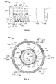
IFC 164.Centerline axis 143,transition piece 174 andswozzle shroud 182 are illustrated for perspective. Figure 5 is an axial cross-sectional view ofexemplary IFC 164 facing downstream and illustrating a firstaxial flow stream 212.Centerline axis 143,diffusion fuel passage 160,tube 156, premixedfuel supply passage 158, radiallyinner tube 150, premixedfuel supply passage 154,convergent tube 146, and convergent tube radiallyouter surface 148 are illustrated for perspective. Only six circumferentially spacedperforations 168 are illustrated in Figure 5. Alternatively,IFC 164 may include any number ofperforations 168.IFC 164 includes radiallyouter wall 166 that defines plurality of substantiallycircular perforations 168. In the exemplary embodiment,IFC 164 includes six axially spacedrows 207 ofperforations 168. For example, in Figure 4, first, second and thirdcircumferential perforation rows IFC 164 may include any number of axially-spacedrows 207 ofperforations 168. - In the exemplary embodiment,
perforations 168 are each formed substantially identical in diameter D1 and the axially-spacedrows 207 are oriented such that six perforations are substantially axially aligned. Moreover, in the exemplary embodiment,perforations 168 are spaced substantially equally circumferentially and axially. The exemplary orientation ofperforations 168 facilitates mitigating a pressure drop acrossIFC 164 that subsequently facilitates improving engine efficiency. Alternatively,IFC 164 may include any number ofperforations 168 arranged in any orientation that enablesIFC 164 to function as described herein. -
IFC 164 may also include anend wall 170 that is positioned on an aft end ofIFC 164 extending betweenwall 166 andsurface 148.IFC 164 may be coupled totube 146 such thatwalls surface 148 define anannular IFC chamber 172 therein.Chamber 172 is coupled in flow communication with combustion chamber cooling passage 129 (shown in Figure 2) viaperforations 168. - In operation, compressed air from
passage 129 flows aroundIFC 164.Perforations 168 facilitate increasing the backpressure around an outer periphery ofIFC 164 by restricting air flow intoIFC 164. The increased backpressure facilitates substantially equalizing air flow throughperforations 168. For example, air flows throughperforations 208 and enterschamber 172 in a plurality of radial air streams 210 (only three illustrated in Figure 4 and only six illustrated in Figure 5). A substantial portion of eachair stream 210 impinges againstsurface 148 and change direction to substantially fill that portion ofchamber 172 defined betweenrow 208 andend cap 170. As such, static pressure is generated within that portion ofchamber 172. Another portion of radial air streams 210 that impingesurface 148 change direction and are channeled towardstransition piece 174. Radial air streams 210 form a boundary layer of air over a portion ofsurface 148 such that a plurality of axial air streams 212 (only six illustrated in Figure 5) are formed and are defined with a first radial and circumferential velocity profile withinchamber 172. Axial air streams 212 that are formed tend to flow substantially parallel to the row ofperforations 208 that admitted the first radial air streams 210. A lesser portion ofair streams 212 flow into that portion ofchamber 172 defined betweenperforations 208. Air streams 212 tend to expand in the radial and circumferential directions as they travel towardstransition piece 174. As such, the radial and circumferential velocity profile of air streams 212 is substantially non-uniform. - Figure 6 is an axial cross-sectional view of
IFC 164 facing downstream, and illustrating a secondaxial flow stream 218.Centerline axis 143,diffusion fuel passage 160,inner tube 156, premixedfuel supply passage 158, radiallyinner tube 150, premixedfuel supply passage 154,convergent tube 146, and convergent tube radiallyouter surface 148 are illustrated for perspective. For clarity, only sixperforations 168 are illustrated in Figure 6. Air flows throughsecond row 214 and enterschamber 172 in a plurality of radial air streams 216 (only three are illustrated in Figure 4 and only six are illustrated in Figure 6). A substantial portion of air streams 216 impinges againstsurface 148 andair streams 212 such that a plurality of second axial air streams 218 are formed that have a second radial and circumferential velocity profile withinchamber 172. Axial air streams 218 tend to form such that circumferential regions ofchamber 172 defined betweenaxial perforations air streams 218 directly underperforations 168 and the portion ofair streams 218 between circumferentiallyadjacent perforations 168. Air streams 218 flowing towardstransition piece 174 tend to expand in the radial and circumferential directions. Therefore, in general, the radial and circumferential velocity profile of air streams 218 is more uniform than the velocity profile of air streams 212. - Figure 7 is an axial cross-sectional view of
IFC 164 facing downstream and illustrating a thirdaxial flow stream 224.Centerline axis 143,diffusion fuel passage 160,inner tube 156, premixedfuel supply passage 158, radiallyinner tube 150, premixedfuel supply passage 154,convergent tube 146, and convergent tube radiallyouter surface 148 are illustrated for perspective. For clarity, only sixperforations 168 are illustrated in Figure 7. Air flows throughthird row 220 and enterschamber 172 in a plurality of radial air streams 222 (only three are illustrated in Figure 4 and only six are illustrated in Figure 7). A first portion of eachair stream 222 impinges againstsurface 148 and a second portion of eachair stream 222 impinges air streams 218 such that a plurality of third axial air streams 224 are formed that have a third radial and circumferential velocity profile withinchamber 172. Axial air streams 224 tend to form such that circumferential regions ofchamber 172 defined betweenperforations air streams 224 directly underperforations 168 and the portion ofair streams 224 between circumferentiallyadjacent perforations 168. Air streams 224 flowing towardstransition piece 174 tend to expand in the radial and circumferential directions. In general, the radial and circumferential velocity profile of air streams 224 is more uniform than the velocity profile of air streams 218. - The iterative process of subsequent radial streams impinging on the composite axial streams induces a flow velocity profile into the air flowing within
chamber 172 across IFC outlet passage 178 (shown in Figure 3) intotransition piece 174 that is substantially constant in the radial direction acrosspassage 178. The substantially uniform velocity profile of air facilitates reducing pockets of rich, or excess, air withinfuel nozzle 122 and combustion chamber 142 that subsequently facilitates a reduction in formation of undesirable combustion byproducts, such as NOx. Similarly, the substantially uniform velocity profile of air facilitates reducing pockets of lean air withinfuel nozzle 122 and combustion chamber 142 thereby facilitating increased flame stability. - The methods and apparatus for assembling and operating a combustor described herein facilitates operation of a gas turbine engine. More specifically, the inlet flow conditioner facilitates a more uniform air flow velocity profile being induced within the fuel nozzle assembly. Such air flow profile facilitates efficiency of combustion and a reduction in undesirable combustion by-products. Moreover, the inlet flow conditioner facilitates reducing capital and maintenance costs, as well as increasing operational reliability.
- Exemplary embodiments of inlet flow conditioners as associated with gas turbine engines are described above in detail. The methods, apparatus and systems are not limited to the specific embodiments described herein nor to the specific illustrated inlet flow conditioner.
- While the invention has been described in terms of various specific embodiments, those skilled in the art will recognize that the invention can be practiced with modification within the spirit and scope of the claims.
Claims (10)
- An inlet flow conditioner (IFC) (164), said IFC comprising an annular chamber (186) at least partially defined therein by a first wall, said first wall comprising a plurality of perforations (168) extending therethrough, said plurality of perforations spaced substantially equidistant circumferentially and are configured to discharge a fluid having a substantially uniform flow profile from said IFC chamber (172).
- An IFC (164) in accordance with Claim 1 wherein said first wall comprises a substantially cylindrical outer wall (166), said IFC further comprises:a substantially cylindrical inner wall (140); anda substantially annular axial end wall (170) extending between said inner and outer walls.
- An IFC (164) in accordance with Claim 2 wherein said inner wall (140), said outer wall (166), and said end wall (170) define said IFC chamber (172).
- An IFC (164) in accordance with Claim 2 or Claim 3 wherein at least a portion of said inner wall (140) and at least a portion of said outer wall (166) define an annular passage (138) that is axially opposite said end wall (170), said passage facilitates coupling said IFC chamber (172) in flow communication with a swozzle assembly (180) that is axially downstream from said IFC chamber.
- An IFC (164) in accordance with any preceding Claim wherein at least a portion of said plurality of perforations (168) forms a substantially axially linear configuration at least partially defining at least one circumferential row.
- An IFC (164) in accordance with any preceding Claim wherein said IFC is coupled in flow communication with a fluid source.
- An IFC (164) in accordance with Claim 6 wherein the fluid source is a gas turbine compressor (102).
- A gas turbine engine (100), said engine comprising:a compressor (102); anda combustor (104) in flow communication with said compressor, said combustor comprising a fuel nozzle assembly (106), said fuel nozzle assembly comprising at least one swozzle assembly (180) and at least one inlet flow conditioner (IFC) (164), said IFC comprising an annular IFC chamber (172) at least partially defined therein by a first wall, said first wall comprising a plurality of perforations (168) extending therethrough, said plurality of perforations spaced substantially equidistant circumferentially and are configured to discharge a fluid having a substantially uniform flow profile from said IFC chamber.
- A gas turbine engine (100) in accordance with Claim 8 wherein said first wall comprises a substantially cylindrical outer wall (166), said IFC (164) further comprises:a substantially cylindrical inner wall (140); anda substantially annular axial end wall (170) extending between said inner and outer walls.
- A gas turbine engine (100) in accordance with Claim 8 or Claim 9 wherein said inner wall (140), said outer wall (166), and said end wall (170) define said IFC chamber (172).
Applications Claiming Priority (1)
| Application Number | Priority Date | Filing Date | Title |
|---|---|---|---|
| US11/443,724 US20070277530A1 (en) | 2006-05-31 | 2006-05-31 | Inlet flow conditioner for gas turbine engine fuel nozzle |
Publications (2)
| Publication Number | Publication Date |
|---|---|
| EP1865261A2 true EP1865261A2 (en) | 2007-12-12 |
| EP1865261A3 EP1865261A3 (en) | 2014-10-08 |
Family
ID=38434316
Family Applications (1)
| Application Number | Title | Priority Date | Filing Date |
|---|---|---|---|
| EP07108515.3A Withdrawn EP1865261A3 (en) | 2006-05-31 | 2007-05-21 | Inlet flow conditioner for gas turbine engine fuel nozzle |
Country Status (4)
| Country | Link |
|---|---|
| US (1) | US20070277530A1 (en) |
| EP (1) | EP1865261A3 (en) |
| JP (1) | JP5269350B2 (en) |
| CN (1) | CN101082422B (en) |
Cited By (3)
| Publication number | Priority date | Publication date | Assignee | Title |
|---|---|---|---|---|
| US8522555B2 (en) | 2009-05-20 | 2013-09-03 | General Electric Company | Multi-premixer fuel nozzle support system |
| EP2813762A1 (en) * | 2013-06-12 | 2014-12-17 | Rolls-Royce plc | Combustion equipment for use in a gas turbine engine |
| WO2022015321A1 (en) * | 2020-07-17 | 2022-01-20 | Siemens Aktiengesellschaft | Premixer injector assembly in gas turbine engine |
Families Citing this family (49)
| Publication number | Priority date | Publication date | Assignee | Title |
|---|---|---|---|---|
| US7887322B2 (en) * | 2006-09-12 | 2011-02-15 | General Electric Company | Mixing hole arrangement and method for improving homogeneity of an air and fuel mixture in a combustor |
| US20090173074A1 (en) * | 2008-01-03 | 2009-07-09 | General Electric Company | Integrated fuel nozzle ifc |
| US8261554B2 (en) * | 2008-09-17 | 2012-09-11 | General Electric Company | Fuel nozzle tip assembly |
| US8701383B2 (en) * | 2009-01-07 | 2014-04-22 | General Electric Company | Late lean injection system configuration |
| US8701418B2 (en) * | 2009-01-07 | 2014-04-22 | General Electric Company | Late lean injection for fuel flexibility |
| US8683808B2 (en) * | 2009-01-07 | 2014-04-01 | General Electric Company | Late lean injection control strategy |
| US8707707B2 (en) * | 2009-01-07 | 2014-04-29 | General Electric Company | Late lean injection fuel staging configurations |
| US8112216B2 (en) * | 2009-01-07 | 2012-02-07 | General Electric Company | Late lean injection with adjustable air splits |
| US8701382B2 (en) * | 2009-01-07 | 2014-04-22 | General Electric Company | Late lean injection with expanded fuel flexibility |
| US8365535B2 (en) * | 2009-02-09 | 2013-02-05 | General Electric Company | Fuel nozzle with multiple fuel passages within a radial swirler |
| EP2253888B1 (en) * | 2009-05-14 | 2013-10-16 | Alstom Technology Ltd | Burner of a gas turbine having a vortex generator with fuel lance |
| US20100326079A1 (en) * | 2009-06-25 | 2010-12-30 | Baifang Zuo | Method and system to reduce vane swirl angle in a gas turbine engine |
| US8371123B2 (en) * | 2009-10-28 | 2013-02-12 | General Electric Company | Apparatus for conditioning airflow through a nozzle |
| US8484978B2 (en) * | 2009-11-12 | 2013-07-16 | General Electric Company | Fuel nozzle assembly that exhibits a frequency different from a natural operating frequency of a gas turbine engine and method of assembling the same |
| US9528447B2 (en) | 2010-09-14 | 2016-12-27 | Jason Eric Green | Fuel mixture control system |
| US8418469B2 (en) * | 2010-09-27 | 2013-04-16 | General Electric Company | Fuel nozzle assembly for gas turbine system |
| US8640974B2 (en) * | 2010-10-25 | 2014-02-04 | General Electric Company | System and method for cooling a nozzle |
| US8826667B2 (en) * | 2011-05-24 | 2014-09-09 | General Electric Company | System and method for flow control in gas turbine engine |
| US8919127B2 (en) * | 2011-05-24 | 2014-12-30 | General Electric Company | System and method for flow control in gas turbine engine |
| US8397514B2 (en) * | 2011-05-24 | 2013-03-19 | General Electric Company | System and method for flow control in gas turbine engine |
| US9046262B2 (en) | 2011-06-27 | 2015-06-02 | General Electric Company | Premixer fuel nozzle for gas turbine engine |
| US8950188B2 (en) | 2011-09-09 | 2015-02-10 | General Electric Company | Turning guide for combustion fuel nozzle in gas turbine and method to turn fuel flow entering combustion chamber |
| US10086694B2 (en) | 2011-09-16 | 2018-10-02 | Gaseous Fuel Systems, Corp. | Modification of an industrial vehicle to include a containment area and mounting assembly for an alternate fuel |
| US9421861B2 (en) | 2011-09-16 | 2016-08-23 | Gaseous Fuel Systems, Corp. | Modification of an industrial vehicle to include a containment area and mounting assembly for an alternate fuel |
| US9738154B2 (en) | 2011-10-17 | 2017-08-22 | Gaseous Fuel Systems, Corp. | Vehicle mounting assembly for a fuel supply |
| US9032735B2 (en) * | 2012-04-26 | 2015-05-19 | General Electric Company | Combustor and a method for assembling the combustor |
| US20130284825A1 (en) * | 2012-04-30 | 2013-10-31 | General Electric Company | Fuel nozzle |
| RU2618801C2 (en) | 2013-01-10 | 2017-05-11 | Дженерал Электрик Компани | Fuel nozzle, end fuel nozzle unit, and gas turbine |
| US9696066B1 (en) | 2013-01-21 | 2017-07-04 | Jason E. Green | Bi-fuel refrigeration system and method of retrofitting |
| US9863366B2 (en) | 2013-03-13 | 2018-01-09 | Rolls-Royce North American Technologies Inc. | Exhaust nozzle apparatus and method for multi stream aircraft engine |
| US9291352B2 (en) | 2013-03-15 | 2016-03-22 | General Electric Company | System having a multi-tube fuel nozzle with an inlet flow conditioner |
| US9546789B2 (en) | 2013-03-15 | 2017-01-17 | General Electric Company | System having a multi-tube fuel nozzle |
| US9316397B2 (en) | 2013-03-15 | 2016-04-19 | General Electric Company | System and method for sealing a fuel nozzle |
| US9303873B2 (en) | 2013-03-15 | 2016-04-05 | General Electric Company | System having a multi-tube fuel nozzle with a fuel nozzle housing |
| US9784452B2 (en) | 2013-03-15 | 2017-10-10 | General Electric Company | System having a multi-tube fuel nozzle with an aft plate assembly |
| USD781323S1 (en) | 2013-03-15 | 2017-03-14 | Jason Green | Display screen with engine control system graphical user interface |
| US9394841B1 (en) | 2013-07-22 | 2016-07-19 | Gaseous Fuel Systems, Corp. | Fuel mixture system and assembly |
| US9845744B2 (en) | 2013-07-22 | 2017-12-19 | Gaseous Fuel Systems, Corp. | Fuel mixture system and assembly |
| CN104048752A (en) * | 2014-06-30 | 2014-09-17 | 四川天微电子有限责任公司 | Flame detection mechanism beneficial for preventing thermal stress damage |
| CN104048315A (en) * | 2014-06-30 | 2014-09-17 | 四川天微电子有限责任公司 | Flame detection mechanism beneficial to guaranteeing sealing performance |
| US9428047B2 (en) | 2014-10-22 | 2016-08-30 | Jason Green | Modification of an industrial vehicle to include a hybrid fuel assembly and system |
| US9931929B2 (en) | 2014-10-22 | 2018-04-03 | Jason Green | Modification of an industrial vehicle to include a hybrid fuel assembly and system |
| US9885318B2 (en) * | 2015-01-07 | 2018-02-06 | Jason E Green | Mixing assembly |
| US9810427B2 (en) * | 2015-03-26 | 2017-11-07 | Ansaldo Energia Switzerland AG | Fuel nozzle with hemispherical dome air inlet |
| US11428413B2 (en) * | 2016-03-25 | 2022-08-30 | General Electric Company | Fuel injection module for segmented annular combustion system |
| KR102340397B1 (en) * | 2020-05-07 | 2021-12-15 | 두산중공업 주식회사 | Combustor, and gas turbine including the same |
| CN112197970B (en) * | 2020-09-21 | 2022-08-26 | 中国航发沈阳发动机研究所 | Design method of speed generator |
| CN112146126B (en) * | 2020-09-24 | 2021-11-12 | 常熟理工学院 | Combined type atomized oil injection structure of air-breathing detonation engine |
| CN112413643B (en) * | 2020-11-23 | 2022-03-11 | 西安航天动力试验技术研究所 | Air injection mechanism for cavity-crossing-preventing high-temperature gas generation device |
Citations (7)
| Publication number | Priority date | Publication date | Assignee | Title |
|---|---|---|---|---|
| US3614283A (en) * | 1966-06-27 | 1971-10-19 | Cabot Corp | High combustion rate burner |
| US3765824A (en) * | 1972-08-02 | 1973-10-16 | Foster Wheeler Corp | Apparatus for determining air flow to a gas burner |
| JPH08270947A (en) * | 1995-03-30 | 1996-10-18 | Toshiba Corp | Gas turbine combustor |
| US5628182A (en) * | 1993-07-07 | 1997-05-13 | Mowill; R. Jan | Star combustor with dilution ports in can portions |
| JP2001289060A (en) * | 2000-04-03 | 2001-10-19 | Mitsubishi Heavy Ind Ltd | Gas turbine |
| US6438961B2 (en) * | 1998-02-10 | 2002-08-27 | General Electric Company | Swozzle based burner tube premixer including inlet air conditioner for low emissions combustion |
| US6634175B1 (en) * | 1999-06-09 | 2003-10-21 | Mitsubishi Heavy Industries, Ltd. | Gas turbine and gas turbine combustor |
Family Cites Families (79)
| Publication number | Priority date | Publication date | Assignee | Title |
|---|---|---|---|---|
| SE224315C1 (en) * | 1958-03-07 | 1969-01-14 | Svenska Flaektfabriken Ab | Device for regulating a volume flow of a gaseous medium passing through a duct or opening for ventilation systems |
| US3747595A (en) * | 1971-06-18 | 1973-07-24 | M Grossan | Jet throat irrigation |
| US4133038A (en) * | 1975-05-26 | 1979-01-02 | Antti Niemi | Method of constructing a continuously operable flotation concentration plant |
| US4196226A (en) * | 1976-07-09 | 1980-04-01 | Stauffer Chemical Company | Alkali metal aluminum phosphate |
| US4260591A (en) * | 1978-12-21 | 1981-04-07 | Stauffer Chemical Company | Process for preparing alkali metal aluminum phosphate |
| US4335154A (en) * | 1978-12-21 | 1982-06-15 | Stauffer Chemical Company | Method for preparing a baked product containing alkali metal aluminum phosphate |
| US4619833A (en) * | 1984-12-13 | 1986-10-28 | General Foods Inc. | Process for producing a rapidly water-soluble, free-flowing, sugar-free dry beverage mix |
| US4715234A (en) * | 1986-07-18 | 1987-12-29 | Daniel Industries, Inc. | Self-cleaning and self-lubricating fluid flowmeter |
| GB2205947B (en) * | 1987-06-19 | 1991-09-04 | British Gas Plc | Flowmeter |
| CA2063820C (en) * | 1989-07-20 | 1998-08-04 | Elizabeth M. Laws | Flow conditioner |
| US5448921A (en) * | 1991-02-05 | 1995-09-12 | Direct Measurement Corporation | Coriolis mass flow rate meter |
| US5361450A (en) * | 1992-12-31 | 1994-11-08 | Zellweger Uster, Inc. | Direct control of fiber testing or processing performance parameters by application of controlled, conditioned gas flows |
| US5370001A (en) * | 1993-06-02 | 1994-12-06 | Ametek, Inc. | Angular momentum mass flowmeter |
| US5392815A (en) * | 1993-08-05 | 1995-02-28 | Pacific Gas And Electric Company | Gradational tube bundle flow conditioner for providing a natural flow profile to facilitate accurate orifice metering in fluid filled conduits |
| GB9319025D0 (en) * | 1993-09-14 | 1993-10-27 | Ans Karsto Metering & Technolo | Flow cobditioner |
| AUPM333394A0 (en) * | 1994-01-13 | 1994-02-03 | Meyer, David Jeffrey | Improved flow conditioners for fire fighting nozzles |
| US5495872A (en) * | 1994-01-31 | 1996-03-05 | Integrity Measurement Partners | Flow conditioner for more accurate measurement of fluid flow |
| JPH0814565A (en) * | 1994-04-28 | 1996-01-19 | Hitachi Ltd | Gas turbine combustor |
| US5483829A (en) * | 1994-06-20 | 1996-01-16 | Ford Motor Company | Environmental flow stand inlet flow conditioner |
| US5592964A (en) * | 1994-08-11 | 1997-01-14 | Traylor; Paul L. | Air gap anti-siphon System |
| JPH08327063A (en) * | 1995-06-01 | 1996-12-10 | Mitsubishi Heavy Ind Ltd | Combustion device |
| US5596969A (en) * | 1995-10-02 | 1997-01-28 | Cummins Engine Company, Inc. | Flow conditioning gas mass sensor |
| US6188179B1 (en) * | 1995-10-24 | 2001-02-13 | Auckland Uniservices Limited | Induction circuits for lighting |
| US5728942A (en) * | 1995-11-28 | 1998-03-17 | Boger; Henry W. | Fluid pressure measuring system for control valves |
| JPH09243078A (en) * | 1996-03-07 | 1997-09-16 | Kansai Electric Power Co Inc:The | Combustion for gas turbine |
| FR2748109B1 (en) * | 1996-04-30 | 1998-07-31 | Schlumberger Ind Sa | DEVICE FOR MEASURING THE FLOW OF A FLOWING FLOW WITH ELEMENT (S) MODIFYING THE SPEED PROFILE OF SAID FLOW |
| US5728950A (en) * | 1996-05-20 | 1998-03-17 | Ametek Aerospace Products, Inc. | Fluid flowmeter |
| US5869772A (en) * | 1996-11-27 | 1999-02-09 | Storer; William James A. | Vortex flowmeter including cantilevered vortex and vibration sensing beams |
| US5780737A (en) * | 1997-02-11 | 1998-07-14 | Fluid Components Intl | Thermal fluid flow sensor |
| US5816907A (en) * | 1997-02-25 | 1998-10-06 | Bowles Fluidics Corporation | Vehicle air outlet with combined flow straightener and shutoff door |
| FR2763678B1 (en) * | 1997-05-23 | 1999-08-13 | Gaz De France | COMPACT VARIABLE PRESSURE GAS COUNTING DEVICE |
| US5959216A (en) * | 1997-07-30 | 1999-09-28 | Schlumberger Industries, S.A. | Method of conditioning a fluid flow, and a fluid flow conditioner |
| US5935426A (en) * | 1997-08-08 | 1999-08-10 | Teledyne Industries, Inc., A California Corporation | Water treatment device with volumetric and time monitoring features |
| US6149801A (en) * | 1997-08-08 | 2000-11-21 | Water Pik, Inc,. | Water treatment device with volumetric monitoring features |
| US5913250A (en) * | 1997-10-29 | 1999-06-15 | Fluid Components Intl | Pressure compensated thermal flow meter |
| FR2776033B1 (en) * | 1998-03-13 | 2000-08-18 | Gaz De France | FLOW CONDITIONER FOR GAS TRANSPORT PIPING |
| JP3485542B2 (en) * | 1998-04-23 | 2004-01-13 | ラティス インテレクチュアル プロパティー リミテッド | Gas mass ratio measurement method |
| US6128072A (en) * | 1998-04-23 | 2000-10-03 | Nova Gas Transmission Ltd. | Optical flow meter integrally mounted to a rigid plate with direct optical access to the interior of a pipe |
| US6048194A (en) * | 1998-06-12 | 2000-04-11 | Precision Combustion, Inc. | Dry, low nox catalytic pilot |
| US6155819A (en) * | 1998-06-12 | 2000-12-05 | Precision Combustion, Inc. | Dry, low NOx catalytic pilot |
| US6270337B1 (en) * | 1998-06-12 | 2001-08-07 | Precision Combustion, Inc. | Dry, low NOx pilot |
| US6065455A (en) * | 1998-08-27 | 2000-05-23 | Allen N. Sharpe | Fuel delivery re-routing harness |
| US6796173B1 (en) * | 1998-10-09 | 2004-09-28 | Fti Flow Technology, Inc. | Fuel flowmeter |
| US6267013B1 (en) * | 1998-11-18 | 2001-07-31 | Stephen T. Stark | Flow anomaly detector |
| US6340243B1 (en) * | 1998-12-03 | 2002-01-22 | Fluid Components Intl | Liquid/gas phase detector system |
| US6473171B1 (en) * | 1999-01-15 | 2002-10-29 | Coors Brewing Company | Biocompatible apparatus for ultrasensitive and rapid detection of contaminants in liquids |
| US6925809B2 (en) * | 1999-02-26 | 2005-08-09 | R. Jan Mowill | Gas turbine engine fuel/air premixers with variable geometry exit and method for controlling exit velocities |
| EP1036988A3 (en) * | 1999-02-26 | 2001-05-16 | R. Jan Mowill | Gas turbine engine fuel/air premixers with variable geometry exit and method for controlling exit velocities |
| US6564651B1 (en) * | 1999-04-27 | 2003-05-20 | James R. Bowers | Modular high-temperature gas flow sensing element for use with a cyclone furnace air flow measuring system |
| US6494105B1 (en) * | 1999-05-07 | 2002-12-17 | James E. Gallagher | Method for determining flow velocity in a channel |
| US6472186B1 (en) * | 1999-06-24 | 2002-10-29 | Andre Quintanar | High speed process and apparatus for amplifying DNA |
| US6439267B2 (en) * | 1999-07-23 | 2002-08-27 | Welker Engineering Company | Adjustable flow diffuser |
| US6289934B1 (en) * | 1999-07-23 | 2001-09-18 | Welker Engineering Company | Flow diffuser |
| GB9929601D0 (en) * | 1999-12-16 | 2000-02-09 | Rolls Royce Plc | A combustion chamber |
| US6647806B1 (en) * | 2000-07-14 | 2003-11-18 | Caldon, Inc. | Turbulence conditioner for use with transit time ultrasonic flowmeters |
| GB0017840D0 (en) * | 2000-07-21 | 2000-09-06 | Bg Intellectual Pty Ltd | A meter for the measurement of multiphase fluids and wet glass |
| JP2002039533A (en) * | 2000-07-21 | 2002-02-06 | Mitsubishi Heavy Ind Ltd | Combustor, gas turbine, and jet engine |
| US6363724B1 (en) * | 2000-08-31 | 2002-04-02 | General Electric Company | Gas only nozzle fuel tip |
| US6453873B1 (en) * | 2000-11-02 | 2002-09-24 | Caterpillar Inc | Electro-hydraulic compression release brake |
| US6460345B1 (en) * | 2000-11-14 | 2002-10-08 | General Electric Company | Catalytic combustor flow conditioner and method for providing uniform gasvelocity distribution |
| US6533065B2 (en) * | 2000-12-19 | 2003-03-18 | Daniel Industries, Inc. | Noise silencer and method for use with an ultrasonic meter |
| CA2350195C (en) * | 2000-12-20 | 2003-06-10 | Duchesnay Inc. | Rapid onset formulation of pyridoxine hydrochloride and doxylamine succinate |
| GB0109616D0 (en) * | 2001-04-19 | 2001-06-06 | Schlumberger Holdings | Down-hole apparatus and method for separating a fluid from a mixture of fluids |
| GB2375601A (en) * | 2001-05-18 | 2002-11-20 | Siemens Ag | Burner apparatus for reducing combustion vibrations |
| US6588889B2 (en) * | 2001-07-16 | 2003-07-08 | Eastman Kodak Company | Continuous ink-jet printing apparatus with pre-conditioned air flow |
| US6669118B2 (en) * | 2001-08-20 | 2003-12-30 | Saint-Gobain Abrasives, Inc. | Coherent jet nozzles for grinding applications |
| CA2399534C (en) * | 2001-08-31 | 2007-01-02 | Mitsubishi Heavy Industries, Ltd. | Gasturbine and the combustor thereof |
| US6651514B2 (en) * | 2001-11-16 | 2003-11-25 | Daniel Industries, Inc. | Dual function flow conditioner and check meter |
| US7008644B2 (en) * | 2002-03-20 | 2006-03-07 | Advanced Inhalation Research, Inc. | Method and apparatus for producing dry particles |
| TW545736U (en) * | 2002-05-01 | 2003-08-01 | Molex Inc | Electrical connector |
| US6629819B1 (en) * | 2002-05-14 | 2003-10-07 | General Electric Company | Steam turbine low pressure inlet flow conditioner and related method |
| US6858067B2 (en) * | 2002-11-12 | 2005-02-22 | Perry Equipment Corporation | Filtration vessel and method for rotary gas compressor system |
| US6868741B2 (en) * | 2003-03-05 | 2005-03-22 | Veris, Inc. | Device and method enabling fluid characteristic measurement utilizing fluid acceleration |
| US6701963B1 (en) * | 2003-05-12 | 2004-03-09 | Horiba Instruments, Inc. | Flow conditioner |
| US6955038B2 (en) * | 2003-07-02 | 2005-10-18 | General Electric Company | Methods and apparatus for operating gas turbine engine combustors |
| JP4043440B2 (en) * | 2004-01-08 | 2008-02-06 | 三菱重工業株式会社 | Gas turbine combustor |
| US7007477B2 (en) * | 2004-06-03 | 2006-03-07 | General Electric Company | Premixing burner with impingement cooled centerbody and method of cooling centerbody |
| US6993916B2 (en) * | 2004-06-08 | 2006-02-07 | General Electric Company | Burner tube and method for mixing air and gas in a gas turbine engine |
| US6983600B1 (en) * | 2004-06-30 | 2006-01-10 | General Electric Company | Multi-venturi tube fuel injector for gas turbine combustors |
-
2006
- 2006-05-31 US US11/443,724 patent/US20070277530A1/en not_active Abandoned
-
2007
- 2007-05-21 EP EP07108515.3A patent/EP1865261A3/en not_active Withdrawn
- 2007-05-31 CN CN2007101087784A patent/CN101082422B/en not_active Expired - Fee Related
- 2007-05-31 JP JP2007144312A patent/JP5269350B2/en not_active Expired - Fee Related
Patent Citations (7)
| Publication number | Priority date | Publication date | Assignee | Title |
|---|---|---|---|---|
| US3614283A (en) * | 1966-06-27 | 1971-10-19 | Cabot Corp | High combustion rate burner |
| US3765824A (en) * | 1972-08-02 | 1973-10-16 | Foster Wheeler Corp | Apparatus for determining air flow to a gas burner |
| US5628182A (en) * | 1993-07-07 | 1997-05-13 | Mowill; R. Jan | Star combustor with dilution ports in can portions |
| JPH08270947A (en) * | 1995-03-30 | 1996-10-18 | Toshiba Corp | Gas turbine combustor |
| US6438961B2 (en) * | 1998-02-10 | 2002-08-27 | General Electric Company | Swozzle based burner tube premixer including inlet air conditioner for low emissions combustion |
| US6634175B1 (en) * | 1999-06-09 | 2003-10-21 | Mitsubishi Heavy Industries, Ltd. | Gas turbine and gas turbine combustor |
| JP2001289060A (en) * | 2000-04-03 | 2001-10-19 | Mitsubishi Heavy Ind Ltd | Gas turbine |
Cited By (6)
| Publication number | Priority date | Publication date | Assignee | Title |
|---|---|---|---|---|
| US8522555B2 (en) | 2009-05-20 | 2013-09-03 | General Electric Company | Multi-premixer fuel nozzle support system |
| US8769956B2 (en) | 2009-05-20 | 2014-07-08 | General Electric Company | Multi-premixer fuel nozzle support system |
| EP2813762A1 (en) * | 2013-06-12 | 2014-12-17 | Rolls-Royce plc | Combustion equipment for use in a gas turbine engine |
| US9689573B2 (en) | 2013-06-12 | 2017-06-27 | Rolls-Royce Plc | Combustion equipment having a sealing member that includes a flexible sleeve |
| WO2022015321A1 (en) * | 2020-07-17 | 2022-01-20 | Siemens Aktiengesellschaft | Premixer injector assembly in gas turbine engine |
| US11708974B2 (en) | 2020-07-17 | 2023-07-25 | Siemens Energy Global GmbH & Co. KG | Premixer injector assembly in gas turbine engine |
Also Published As
| Publication number | Publication date |
|---|---|
| CN101082422B (en) | 2011-06-08 |
| CN101082422A (en) | 2007-12-05 |
| EP1865261A3 (en) | 2014-10-08 |
| JP2007322120A (en) | 2007-12-13 |
| JP5269350B2 (en) | 2013-08-21 |
| US20070277530A1 (en) | 2007-12-06 |
Similar Documents
| Publication | Publication Date | Title |
|---|---|---|
| EP1865261A2 (en) | Inlet flow conditioner for gas turbine engine fuel nozzle | |
| US8484978B2 (en) | Fuel nozzle assembly that exhibits a frequency different from a natural operating frequency of a gas turbine engine and method of assembling the same | |
| US9140454B2 (en) | Bundled multi-tube nozzle for a turbomachine | |
| US8104286B2 (en) | Methods and systems to enhance flame holding in a gas turbine engine | |
| US9200571B2 (en) | Fuel nozzle assembly for a gas turbine engine | |
| US8438851B1 (en) | Combustor assembly for use in a turbine engine and methods of assembling same | |
| JP5947515B2 (en) | Turbomachine with mixing tube element with vortex generator | |
| EP2669580B1 (en) | Fuel injection assembly for use in turbine engines and method of assembling same | |
| US20110107769A1 (en) | Impingement insert for a turbomachine injector | |
| US20100192578A1 (en) | System and method for suppressing combustion instability in a turbomachine | |
| US20080276622A1 (en) | Fuel nozzle and method of fabricating the same | |
| CN113091094B (en) | Gas turbine combustor nozzle and method for premixing fuel and air in nozzle | |
| JP6900198B2 (en) | Gas cartridge for premixed fuel nozzle | |
| US8297059B2 (en) | Nozzle for a turbomachine | |
| US11566790B1 (en) | Methods of operating a turbomachine combustor on hydrogen | |
| US11280495B2 (en) | Gas turbine combustor fuel injector flow device including vanes | |
| EP2597373B1 (en) | Swirler assembly with compressor discharge injection to vane surface | |
| CN116412412A (en) | Burner with dilution opening | |
| CN110736108A (en) | Burner assembly for a heat engine | |
| EP4202305A1 (en) | Fuel nozzle and swirler | |
| US11725819B2 (en) | Gas turbine fuel nozzle having a fuel passage within a swirler | |
| US20230266006A1 (en) | Multi pressure drop swirler ferrule plate | |
| US20230266002A1 (en) | Coupling a fuel nozzle purge flow directly to a swirler | |
| US20230213194A1 (en) | Turbine engine fuel premixer | |
| WO2023140180A1 (en) | Combustor and gas turbine |
Legal Events
| Date | Code | Title | Description |
|---|---|---|---|
| PUAI | Public reference made under article 153(3) epc to a published international application that has entered the european phase |
Free format text: ORIGINAL CODE: 0009012 |
|
| AK | Designated contracting states |
Kind code of ref document: A2 Designated state(s): AT BE BG CH CY CZ DE DK EE ES FI FR GB GR HU IE IS IT LI LT LU LV MC MT NL PL PT RO SE SI SK TR |
|
| AX | Request for extension of the european patent |
Extension state: AL BA HR MK YU |
|
| PUAL | Search report despatched |
Free format text: ORIGINAL CODE: 0009013 |
|
| AK | Designated contracting states |
Kind code of ref document: A3 Designated state(s): AT BE BG CH CY CZ DE DK EE ES FI FR GB GR HU IE IS IT LI LT LU LV MC MT NL PL PT RO SE SI SK TR |
|
| AX | Request for extension of the european patent |
Extension state: AL BA HR MK RS |
|
| RIC1 | Information provided on ipc code assigned before grant |
Ipc: F23R 3/28 20060101ALI20140903BHEP Ipc: F23R 3/26 20060101AFI20140903BHEP |
|
| STAA | Information on the status of an ep patent application or granted ep patent |
Free format text: STATUS: THE APPLICATION IS DEEMED TO BE WITHDRAWN |
|
| 18D | Application deemed to be withdrawn |
Effective date: 20141202 |