EP1882851A2 - Verfahren zur Errichtung einer Windenergieanlage, Windenergieanlage - Google Patents
Verfahren zur Errichtung einer Windenergieanlage, Windenergieanlage Download PDFInfo
- Publication number
- EP1882851A2 EP1882851A2 EP07120659A EP07120659A EP1882851A2 EP 1882851 A2 EP1882851 A2 EP 1882851A2 EP 07120659 A EP07120659 A EP 07120659A EP 07120659 A EP07120659 A EP 07120659A EP 1882851 A2 EP1882851 A2 EP 1882851A2
- Authority
- EP
- European Patent Office
- Prior art keywords
- power module
- wind turbine
- foundation
- tower
- wind
- Prior art date
- Legal status (The legal status is an assumption and is not a legal conclusion. Google has not performed a legal analysis and makes no representation as to the accuracy of the status listed.)
- Granted
Links
- 238000000034 method Methods 0.000 title claims abstract description 6
- 230000007704 transition Effects 0.000 claims 1
- 238000010276 construction Methods 0.000 abstract description 6
- 239000000969 carrier Substances 0.000 description 5
- 238000013461 design Methods 0.000 description 2
- 238000009434 installation Methods 0.000 description 2
- 230000002787 reinforcement Effects 0.000 description 2
- 229910000831 Steel Inorganic materials 0.000 description 1
- 230000005540 biological transmission Effects 0.000 description 1
- 238000011161 development Methods 0.000 description 1
- 230000018109 developmental process Effects 0.000 description 1
- 238000009826 distribution Methods 0.000 description 1
- 230000000694 effects Effects 0.000 description 1
- 238000010616 electrical installation Methods 0.000 description 1
- 238000004519 manufacturing process Methods 0.000 description 1
- 238000005259 measurement Methods 0.000 description 1
- 238000009417 prefabrication Methods 0.000 description 1
- 238000002360 preparation method Methods 0.000 description 1
- 239000010959 steel Substances 0.000 description 1
- 238000012546 transfer Methods 0.000 description 1
Images


Classifications
-
- F—MECHANICAL ENGINEERING; LIGHTING; HEATING; WEAPONS; BLASTING
- F03—MACHINES OR ENGINES FOR LIQUIDS; WIND, SPRING, OR WEIGHT MOTORS; PRODUCING MECHANICAL POWER OR A REACTIVE PROPULSIVE THRUST, NOT OTHERWISE PROVIDED FOR
- F03D—WIND MOTORS
- F03D1/00—Wind motors with rotation axis substantially parallel to the air flow entering the rotor
-
- F—MECHANICAL ENGINEERING; LIGHTING; HEATING; WEAPONS; BLASTING
- F03—MACHINES OR ENGINES FOR LIQUIDS; WIND, SPRING, OR WEIGHT MOTORS; PRODUCING MECHANICAL POWER OR A REACTIVE PROPULSIVE THRUST, NOT OTHERWISE PROVIDED FOR
- F03D—WIND MOTORS
- F03D13/00—Assembly, mounting or commissioning of wind motors; Arrangements specially adapted for transporting wind motor components
- F03D13/20—Arrangements for mounting or supporting wind motors; Masts or towers for wind motors
- F03D13/22—Foundations specially adapted for wind motors
-
- F—MECHANICAL ENGINEERING; LIGHTING; HEATING; WEAPONS; BLASTING
- F03—MACHINES OR ENGINES FOR LIQUIDS; WIND, SPRING, OR WEIGHT MOTORS; PRODUCING MECHANICAL POWER OR A REACTIVE PROPULSIVE THRUST, NOT OTHERWISE PROVIDED FOR
- F03D—WIND MOTORS
- F03D13/00—Assembly, mounting or commissioning of wind motors; Arrangements specially adapted for transporting wind motor components
- F03D13/10—Assembly of wind motors; Arrangements for erecting wind motors
-
- F—MECHANICAL ENGINEERING; LIGHTING; HEATING; WEAPONS; BLASTING
- F03—MACHINES OR ENGINES FOR LIQUIDS; WIND, SPRING, OR WEIGHT MOTORS; PRODUCING MECHANICAL POWER OR A REACTIVE PROPULSIVE THRUST, NOT OTHERWISE PROVIDED FOR
- F03D—WIND MOTORS
- F03D13/00—Assembly, mounting or commissioning of wind motors; Arrangements specially adapted for transporting wind motor components
- F03D13/20—Arrangements for mounting or supporting wind motors; Masts or towers for wind motors
-
- F—MECHANICAL ENGINEERING; LIGHTING; HEATING; WEAPONS; BLASTING
- F03—MACHINES OR ENGINES FOR LIQUIDS; WIND, SPRING, OR WEIGHT MOTORS; PRODUCING MECHANICAL POWER OR A REACTIVE PROPULSIVE THRUST, NOT OTHERWISE PROVIDED FOR
- F03D—WIND MOTORS
- F03D80/00—Details, components or accessories not provided for in groups F03D1/00 - F03D17/00
- F03D80/80—Arrangement of components within nacelles or towers
- F03D80/82—Arrangement of components within nacelles or towers of electrical components
- F03D80/85—Cabling
-
- F—MECHANICAL ENGINEERING; LIGHTING; HEATING; WEAPONS; BLASTING
- F03—MACHINES OR ENGINES FOR LIQUIDS; WIND, SPRING, OR WEIGHT MOTORS; PRODUCING MECHANICAL POWER OR A REACTIVE PROPULSIVE THRUST, NOT OTHERWISE PROVIDED FOR
- F03D—WIND MOTORS
- F03D9/00—Adaptations of wind motors for special use; Combinations of wind motors with apparatus driven thereby; Wind motors specially adapted for installation in particular locations
- F03D9/20—Wind motors characterised by the driven apparatus
- F03D9/25—Wind motors characterised by the driven apparatus the apparatus being an electrical generator
- F03D9/255—Wind motors characterised by the driven apparatus the apparatus being an electrical generator connected to electrical distribution networks; Arrangements therefor
-
- F—MECHANICAL ENGINEERING; LIGHTING; HEATING; WEAPONS; BLASTING
- F05—INDEXING SCHEMES RELATING TO ENGINES OR PUMPS IN VARIOUS SUBCLASSES OF CLASSES F01-F04
- F05B—INDEXING SCHEME RELATING TO WIND, SPRING, WEIGHT, INERTIA OR LIKE MOTORS, TO MACHINES OR ENGINES FOR LIQUIDS COVERED BY SUBCLASSES F03B, F03D AND F03G
- F05B2230/00—Manufacture
- F05B2230/50—Building or constructing in particular ways
-
- F—MECHANICAL ENGINEERING; LIGHTING; HEATING; WEAPONS; BLASTING
- F05—INDEXING SCHEMES RELATING TO ENGINES OR PUMPS IN VARIOUS SUBCLASSES OF CLASSES F01-F04
- F05B—INDEXING SCHEME RELATING TO WIND, SPRING, WEIGHT, INERTIA OR LIKE MOTORS, TO MACHINES OR ENGINES FOR LIQUIDS COVERED BY SUBCLASSES F03B, F03D AND F03G
- F05B2230/00—Manufacture
- F05B2230/60—Assembly methods
-
- Y—GENERAL TAGGING OF NEW TECHNOLOGICAL DEVELOPMENTS; GENERAL TAGGING OF CROSS-SECTIONAL TECHNOLOGIES SPANNING OVER SEVERAL SECTIONS OF THE IPC; TECHNICAL SUBJECTS COVERED BY FORMER USPC CROSS-REFERENCE ART COLLECTIONS [XRACs] AND DIGESTS
- Y02—TECHNOLOGIES OR APPLICATIONS FOR MITIGATION OR ADAPTATION AGAINST CLIMATE CHANGE
- Y02E—REDUCTION OF GREENHOUSE GAS [GHG] EMISSIONS, RELATED TO ENERGY GENERATION, TRANSMISSION OR DISTRIBUTION
- Y02E10/00—Energy generation through renewable energy sources
- Y02E10/70—Wind energy
- Y02E10/72—Wind turbines with rotation axis in wind direction
-
- Y—GENERAL TAGGING OF NEW TECHNOLOGICAL DEVELOPMENTS; GENERAL TAGGING OF CROSS-SECTIONAL TECHNOLOGIES SPANNING OVER SEVERAL SECTIONS OF THE IPC; TECHNICAL SUBJECTS COVERED BY FORMER USPC CROSS-REFERENCE ART COLLECTIONS [XRACs] AND DIGESTS
- Y02—TECHNOLOGIES OR APPLICATIONS FOR MITIGATION OR ADAPTATION AGAINST CLIMATE CHANGE
- Y02E—REDUCTION OF GREENHOUSE GAS [GHG] EMISSIONS, RELATED TO ENERGY GENERATION, TRANSMISSION OR DISTRIBUTION
- Y02E10/00—Energy generation through renewable energy sources
- Y02E10/70—Wind energy
- Y02E10/728—Onshore wind turbines
-
- Y—GENERAL TAGGING OF NEW TECHNOLOGICAL DEVELOPMENTS; GENERAL TAGGING OF CROSS-SECTIONAL TECHNOLOGIES SPANNING OVER SEVERAL SECTIONS OF THE IPC; TECHNICAL SUBJECTS COVERED BY FORMER USPC CROSS-REFERENCE ART COLLECTIONS [XRACs] AND DIGESTS
- Y02—TECHNOLOGIES OR APPLICATIONS FOR MITIGATION OR ADAPTATION AGAINST CLIMATE CHANGE
- Y02P—CLIMATE CHANGE MITIGATION TECHNOLOGIES IN THE PRODUCTION OR PROCESSING OF GOODS
- Y02P70/00—Climate change mitigation technologies in the production process for final industrial or consumer products
- Y02P70/50—Manufacturing or production processes characterised by the final manufactured product
-
- Y—GENERAL TAGGING OF NEW TECHNOLOGICAL DEVELOPMENTS; GENERAL TAGGING OF CROSS-SECTIONAL TECHNOLOGIES SPANNING OVER SEVERAL SECTIONS OF THE IPC; TECHNICAL SUBJECTS COVERED BY FORMER USPC CROSS-REFERENCE ART COLLECTIONS [XRACs] AND DIGESTS
- Y10—TECHNICAL SUBJECTS COVERED BY FORMER USPC
- Y10T—TECHNICAL SUBJECTS COVERED BY FORMER US CLASSIFICATION
- Y10T29/00—Metal working
- Y10T29/49—Method of mechanical manufacture
- Y10T29/49826—Assembling or joining
Definitions
- the invention relates to a method for the construction of a wind energy plant and the wind energy plant in its embodiment itself.
- the object of the invention is therefore to develop a method by means of which the erection of wind turbines can be carried out even more favorably, but above all faster.
- the essential power modules so transformer, cabinets, etc. to place on the foundation and only then to build the tower, so that the entire power modules after construction of the tower are protected in the area of the tower foundation or in the lower part of the tower and rest safely on the tower foundation.
- the power modules are already prefabricated as far as possible and mounted on carriers, so that by a crane that you anyway needed to build a wind turbine, the power modules can be placed on the tower foundation and the entire production, especially the laying of cables and the entire operation preparation
- the wind turbine can take place in a sheltered room by adjusting individual control modules, installing the control cabinets, etc., and these activities can be started after the tower has been erected.
- the carriers of the power modules have support feet, which in turn rest on prepositioned plates on the tower foundation. These plates are already embedded in the creation of the foundation before certain positions and fixed with the foundation, so that a later installation of the power modules can be made in a very simple manner.
- empty conduits are provided in the foundation of the wind turbine for the cables that lead out of the wind turbine, so in particular the power transmission cable, control cable, etc. and this empty spout in predetermined Positions are fixed.
- the trusses by means of holding arms, which in turn are fixed in parts of the foundation or in the underscoring section of a tower, held.
- the measures according to the invention therefore also facilitate the entire electrical installation of the wind energy plant by means of a prefabrication of individual modules such as the empty-tube spreaders, power module carriers, etc., already in the foundation wall direction.
- the entire construction time of the wind turbine can be significantly shortened. Also can be reduced with the invention, the cost of the entire construction of the wind turbine without any technical disadvantages must be taken into account.
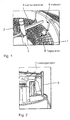
- Figure 1 shows a plan view of a pre-established foundation (without concrete filling) with a steel reinforcement 1 and 2, on an empty tube 3, which is held by a strut 4 with a lowermost tower section adjacent to the reinforcement. Furthermore, support plates 5 can be seen, which are for holding arms 6 in the lowest tower section, (which is no longer visible after the erection of the wind turbine) are mounted.
- the empty tube 3 is used later for receiving cables, such as the power cable through which the entire electrical energy of the wind turbine to the network is dissipated via underground cables.
- cables such as the power cable through which the entire electrical energy of the wind turbine to the network is dissipated via underground cables.
- cables such as the power cable through which the entire electrical energy of the wind turbine to the network is dissipated via underground cables.
- cables such as the power cable through which the entire electrical energy of the wind turbine to the network is dissipated via underground cables.
- Figure 2 shows the foundation section after filling the concrete.
- the conduits remain in their prefixed position and also the support plates are embedded in concrete, it must be ensured during concreting that the support plates rest snugly on the structural concrete and thus ensure a flat load transfer.
- the concrete extends to the top of the support plates and is carefully worked on the edge of the plate.
- the retaining arms for holding the support plates as well as the traverses for fixing the conduits can be removed and reused for the construction of other facilities.
- the tower is not placed on the lowest foundations for the tower section for the further erection of the wind energy plant, as is the case until then. Instead, a power module 7 is placed on the support plates 5 (FIGS. 2, 3 and 4).
- Such a power module 7 is shown in Figure 3 in a two-part design, wherein the power module can also consist of other parts.
- the two parts of the power module 7 are superimposed in the example shown and the entire power module consists of two superimposed carriers 8, which in turn record significant parts of the power modules, so for example, the transformer, inverters, cabinets, medium voltage system, etc ..
- the superposed carrier 8 are constructed in the manner of a frame and fit exactly one above the other, so that a reliable attachment is guaranteed against each other.
- the individual carriers have, inter alia, four - a rectangle spanning - vertically oriented spars, which are interconnected are. These spars are bolted together at their bottom and top.
- the outer dimensions of the power module with respect to width and length are smaller than the inner diameter of the tower in the lower tower area / foundation area.
- the wind turbine After erection of the tower, the wind turbine is equipped as usual with the machine house, the rotor is mounted and for commissioning corresponding electrical connections between the generator and the power module 7 are made and there is also the connection of the power module (output of the transformer) to the power grid ,
- conduits or devices provided for the cable bushing are prefixed in a certain prescribed position, the connection between the power module and the network can be made very quickly and cheaply, the cable lengths are minimal overall, because the conduits are positioned where they come exactly to the plant with the corresponding parts of the power module.
- the access of the wind turbine is no longer necessarily in the fixed foundation area by a conventional door, but by a door (access), which is positioned so that it is in the range above the high or medium voltage leading parts of the power module opens.
- a corresponding ladder or stairs may be provided on the outside of the tower.
- a corresponding intermediate platform is provided, which can commit the staff who enters the tower, then in the interior of the tower continue to rise in the wind turbine or make adjustments to various control devices or read measurement data.
- a wind turbine of the type according to the invention is one which regularly has more than 100 kW rated power, preferably has a rated power in the range of 500 kW, 1 MW, 1.5 MW or significantly more.
- the intermediate platform is provided with a closable plate, through which the personnel can get into the lower part of the power module. Closure of the flap further secures the lower part of the power module against unauthorized access.
- the inner diameter of the tower in the foundation area can be several meters, so that the entire area there is eg 100 m 2 or more and therefore also a sufficiently large area for receiving the power modules is available.
- power module means the middle or high voltage leading part of the wind turbine.
- the units such as transformers or inverters or emergency switches as well as the medium-voltage switchgear cabinet or the low-voltage distributors.
Abstract
Description
- Die Erfindung betrifft ein Verfahren zur Errichtung einer Windenergieanlage sowie die Windenergieanlage in ihrer Ausgestaltung selbst.
- Bisher wird bei der Errichtung von Windenergieanlagen zunächst ein Fundament erstellt, dann der Turm der Windenergieanlage errichtet und anschließend das Maschinenhaus an der Turmspitze ausgerüstet und der Rotor mit den Rotorblättern angebracht. Hiernach werden die elektrischen Leistungsmodule wie der Transformator, Schaltschränke, gegebenenfalls Wechselrichter, Mittelspannungsanlage, Niederspannungsverteilung usw. installiert. Dies geschieht fast immer in einem eigenen kleinen Gebäude außerhalb der Windenergieanlage.
- In
DE 198 16 483.1 ist bereits auch schon vorgeschlagen worden, den Transformator innen im Turm unterzubringen, so dass es der Errichtung eines eigenen Trafogebäudes mit eigenem Fundament nicht mehr bedarf. - Aufgabe der Erfindung ist es nun, ein Verfahren zu entwickeln, mittels dem die Errichtung von Windenergieanlagen noch günstiger, vor allem aber auch schneller vorgenommen werden kann.
- Die Aufgabe wird mit einem Verfahren mit den Merkmalen nach Anspruch 1 und einer Windenergieanlage mit den Merkmalen nach Anspruch 2 gelöst. Vorteilhafte Weiterbildungen sind in den Unteransprüchen beschrieben.
- Erfindungsgemäß wird vorgeschlagen, abweichend von der bisherigen Konstruktion von Windenergieanlagen, nach Errichtung des Fundaments der Windenergieanlage die wesentlichen Leistungsmodule, also Trafo, Schaltschränke usw. auf dem Fundament zu platzieren und erst danach den Turm zu errichten, so dass die gesamten Leistungsmodule nach Errichtung des Turms im Bereich des Turmfundamentes bzw. im unteren Teil des Turms geschützt sind und sicher auf dem Turmfundament ruhen.
- Die Leistungsmodule sind soweit wie möglich bereits vorgefertigt und auf Trägern montiert, so dass durch einen Kran, den man ohnehin zur Errichtung einer Windenergieanlage benötigt, die Leistungsmodule auf dem Turmfundament aufgestellt werden können und die gesamte Betriebsfertigung, insbesondere das Verlegen von Kabeln sowie die gesamte Betriebsvorbereitung der Windenergieanlage durch Einstellung einzelner Steuerungsmodule, Einrüstung der Schaltschränke etc. in einem geschützten Raum stattfinden kann und mit diesen Tätigkeiten begonnen werden kann, nachdem der Turm errichtet wurde.
- Besonders vorteilhaft ist es auch, wenn die Träger der Leistungsmodule Stützfüße aufweisen, die wiederum auf vorpositionierten Platten auf dem Turmfundament ruhen. Diese Platten werden bereits bei der Erstellung des Fundaments vor bestimmten Positionen eingelassen und mit dem Fundament fixiert, so dass auch eine spätere Aufstellung der Leistungsmodule auf sehr einfache Art und Weise vorgenommen werden kann.
- Schließlich ist es auch sehr vorteilhaft, wenn für die Kabel, die aus der Windenergieanlage herausführen, also insbesondere die Stromübertragungskabel, Steuerungskabel etc. Leerrohrtraversen im Fundament der Windenergieanlage vorgesehen sind und diese Leerrohrtraversen in vorbestimmten Positionen fixiert liegen. Hierzu werden die Traversen mittels Haltearmen, die ihrerseits wiederum in Teilen des Fundaments oder in der untersitzenden Sektion eines Turmes fixiert sind, gehalten. Durch diese Leerrohrtraversen kann der Bereich der Kabelzuführung exakt vorbestimmt werden und vor allem auch so gelegt werden, dass die Kabel, die aus dem Leistungsmodul in das Fundament reichen, über einen kürzesten und optimalen Kabelweg verfügen.
- Die erfindungsgemäßen Maßnahmen erleichtern also auch die gesamte elektrische Einrichtung der Windenergieanlage durch eine Vorfertigung von einzelnen Modulen wie den Leerrohrtraversen, Leistungsmodulträgern etc. bereits bei der Fundamenterrichtung.
- Mit den erfindungsgemäßen Maßnahmen lässt sich die gesamte Errichtungszeit der Windenergieanlage deutlich verkürzen. Auch lassen sich mit der Erfindung die Kosten für die gesamte Errichtung der Windenergieanlage verringern, ohne dass irgendwelche technischen Nachteile in Kauf genommen werden müssen.
- Die Erfindung wird nachfolgend anhand eines in einer Zeichnung ausgeführten Beispiels näher erläutert.
- Figur 1 zeigt eine Aufsicht auf ein voreingerichtetes Fundament (ohne Betonfüllung) mit einer Stahlarmierung 1 und 2, an einem Leerrohr 3, welches über eine Verstrebung 4 mit einer an die Armierung angrenzende unterste Turmsektion gehalten wird. Ferner sind Tragplatten 5 zu erkennen, die für Haltearme 6 in der untersten Turmsektion, (die später nach der Errichtung der Windenergieanlage nicht mehr zu sehen ist) angebracht sind.
- Das Leerrohr 3 dient später zur Aufnahme von Kabeln, beispielsweise der Stromkabel, über die die gesamte elektrische Energie der Windenergieanlage zum Netz über Erdkabel abgeführt wird. Hierzu ist oftmals nicht nur ein einziges Rohr, sondern mehrere Rohre vorgesehen.
- Figur 2 zeigt die Fundamentsektion nach Einfüllung des Betons. Hierbei ist zu sehen, dass die Leerrohre in ihrer vorfixierten Position verbleiben und auch die Tragplatten mit einbetoniert sind, wobei beim Betonieren darauf zu achten ist, dass die Tragplatten satt auf dem Konstruktionsbeton aufliegen und so einen flächigen Lastabtrag gewährleisten. Der Beton reicht bis zur Oberkante der Tragplatten und ist sorgfältig an den Plattenrand angearbeitet.
- Nach Aushärtung des Betons können die Haltearme zum Halten der Tragplatten wie auch die Traversen zur Fixierung der Leerrohre abmontiert und für die Errichtung weiterer Anlagen wiederverwendet werden.
- Nach dem Aushärten des Betons wird zur weiteren Errichtung der Windenergieanlage nicht - wie bis dahin üblich - der Turm auf das unterste Fundament für die Turmsektion aufgesetzt, sondern es wird zunächst ein Leistungsmodul 7 auf die Tragplatten 5 gestellt (Figuren 2, 3 und 4).
- Ein solches Leistungsmodul 7 ist in Figur 3 in einer zweiteiligen Ausführung gezeigt, wobei das Leistungsmodul auch aus weiteren Teilen bestehen kann.
- Die beiden Teile des Leistungsmoduls 7 sind im dargestellten Beispiel übereinander gestellt und das gesamte Leistungsmodul besteht aus zwei übereinandergestellten Trägern 8, die ihrerseits wiederum wesentliche Teile der Leistungsmodule aufnehmen, also beispielsweise den Transformator, Wechselrichter, Schaltschränke, Mittelspannungsanlage etc..
- Die übereinandergestellten Träger 8 sind nach Art eines Rahmens aufgebaut und passen exakt übereinander, so dass auch eine zuverlässige Befestigung gegeneinander gewährleistet ist.
- Die einzelnen Träger weisen unter anderem vier - ein Rechteck aufspannende - vertikal ausgerichtete Holme auf, die untereinander verbunden sind. Diese Holme sind an ihrer Unter- und Oberseite miteinander verschraubt.
- Nach der Aufstellung des elektrischen Leistungsmoduls auf dem Fundament wird der Turm 9 errichtet (Figur 4) und hierbei über das Leistungsmodul gestülpt. Dazu sind die äußeren Abmaße des Leistungsmoduls hinsichtlich Breite und Länge geringer als der Innendurchmesser des Turms im unteren Turmbereich/Fundamentbereich.
- Nach Errichtung des Turms wird die Windenergieanlage wie üblich mit dem Maschinenhaus ausgestattet, der Rotor wird montiert und für die Inbetriebnahme werden entsprechende elektrische Verbindungen zwischen dem Generator und dem Leistungsmodul 7 hergestellt und es erfolgt auch der Anschluss des Leistungsmoduls (Ausgang des Transformators) an das Stromversorgungsnetz.
- Wenn die vorbeschriebenen Leerrohre bzw. für die Kabeldurchführung vorgesehenen Einrichtungen in bestimmter vorbeschriebener Position vorfixiert sind, kann auch die Verbindung zwischen dem Leistungsmodul und dem Netz äußerst schnell und günstig hergestellt werden, wobei die Kabellängen insgesamt minimal sind, weil die Leerrohre dort positioniert sind, wo sie genau zur Anlage mit den entsprechenden Teilen des Leistungsmoduls kommen.
- Bei der erfindungsgemäßen Windenergieanlage ist es auch vorteilhaft, wenn der Zugang der Windenergieanlage nicht mehr unbedingt im festen Fundamentbereich durch eine übliche Tür erfolgt, sondern durch eine Tür (Zugang), die so positioniert ist, dass sie in den Bereich oberhalb der Hoch- oder Mittelspannung führenden Teile des Leistungsmoduls mündet. Hierzu kann an der Außenseite des Turms eine entsprechende Leiter oder Treppe vorgesehen sein. Diese Positionierung der Zugangstür hat den Vorteil, dass das Personal, welches die Anlage häufiger betreten muss, sich nicht stets an den Hoch- oder Mittelspannung führenden Teilen des Leistungsmoduls vorbei bewegen muss, während die Anlage in Betrieb ist. Damit wird auch sichergestellt, dass nicht unvorhergesehenerweise oder aus Versehen während des Betriebs der Windenergieanlage jemand sich in unmittelbarer Nähe des Leistungsmoduls befindet und hierbei in Berührung mit spannungs- oder stromgeführten Teilen kommt, was einen großen Unfall verursachen könnte.
- Im Bereich der Zugangstür des Turms ist dann eine entsprechende Zwischenplattform vorgesehen, die das Personal, welches den Turm betritt, begehen kann, um dann im Inneren des Turms weiter in die Windenergieanlage hoch zu steigen oder an verschiedenen Steuereinrichtungen Einstellungen vorzunehmen oder auch Messdaten abzulesen.
- Bei einer Windenergieanlage des erfindungsgemäßen Typs handelt es sich um eine solche, die regelmäßig über mehr als 100 kW Nennleistung verfügt, vorzugsweise eine Nennleistung im Bereich von 500 kW, 1 MW, 1,5 MW oder deutlich mehr aufweist. Bevorzugt ist die Zwischenplattform mit einer verschließbaren Platte versehen, durch die das Personal in den unteren Bereich des Leistungsmoduls einsteigen kann. Mit dem Verschluss der Klappe ist eine weitere Sicherung des unteren Teils des Leistungsmoduls gegen unbefugten Zugriff gewährleistet.
- Der innere Durchmesser des Turms im Fundamentbereich kann dabei mehrere Meter betragen, so dass auch die gesamte Fläche dort z.B. 100 m2 oder mehr beträgt und daher auch eine ausreichend große Fläche zur Aufnahme der Leistungsmodule zur Verfügung steht. Soweit in dieser Anmeldung der Begriff "Leistungsmodul" verwendet wird, so ist damit der Mittel- bzw. Hochspannungsführende Teil der Windenergieanlage gemeint. Dies sind insbesondere die Aggregate wie Transformator oder Wechselrichter oder Notschalter sowie der Mittelspannungsschaltschrank oder auch die Niederspannungsverteiler.
Claims (5)
- Verfahren zur Errichtung einer Windenergieanlage mit einem Turm (9), der auf einem Fundament gründet sowie einem elektrischen Leistungsmodul (7), im Wesentlichen bestehend aus einem Transformator und gegebenenfalls einem Wechselrichter oder anderen elektrischen Einrichtungen, wie z.B. Schaltschränken, die zur Steuerung der Windenergieanlage und/oder zur Durchleitung der elektrischen Leistung, die vom Generator der Windenergieanlage zur Verfügung gestellt und in ein Netz eingespeist wird, vorgesehen ist, dadurch gekennzeichnet, dass das Leistungsmodul (7) vor Errichtung des Turms auf dem Turmfundament gelagert wird.
- Windenergieanlage bestehend aus einem Turm, welcher auf einem Fundament gründet und einem Leistungsmodul, wobei das Leistungsmodul wenigstens einen Transformator aufweist, mittels dem die elektrische Energie, die vom Generator der Windenergieanlage zur Verfügung gestellt wird, auf eine mittlere und/oder Hochspannung transformiert wird, dass das Leistungsmodul darüber hinaus weitere Einheiten enthält, mittels denen die elektrische Energie, die vom Generator der Windenergieanlage bereitgestellt wird, gesteuert und/oder geleitet wird, und/oder aufgewertet dadurch gekennzeichnet, dass das Leistungsmodul einen Träger aufweist, der auf dem Fundament der Windenergieanlage aufgesetzt ist und dass der Träger die elektrischen Einrichtungen des Leistungsmoduls, wie z.B. der Transformator aufnimmt, und dass Breite und/oder Länge des Leistungsmoduls geringer sind als der Durchmesser des Turms der Windenergieanlage im Fundamentbereich.
- Windenergieanlage nach Anspruch 2,
dadurch gekennzeichnet, dass das Leistungsmodul zweiteilig ausgebildet ist, wobei die beiden Teile aufeinander gestellt sind und die Träger im Übergangsbereich zwischen dem ersten und zweiten Teil so ausgebildet sind, dass sie aufeinander passen und gegen einander befestigt sind. - Windenergieanlage nach einem der Ansprüche 2 oder 3,
dadurch gekennzeichnet, dass das Leistungsmodul aus einem Transformator und einem Wechselrichter und wenigstens einem Schaltschrank zur Aufnahme von elektrischen Steuerungseinrichtungen der Windenergieanlagen besteht. - Windenergieanlage nach einem der vorhergehenden Ansprüche,
dadurch gekennzeichnet, dass im Fundament der Windenergieanlage Leerrohre (3) zur Aufnahme von Kabeln angeordnet sind und die Leerrohre vor der Feststellung des Fundaments mit den Traversen fixiert sind.
Applications Claiming Priority (3)
| Application Number | Priority Date | Filing Date | Title |
|---|---|---|---|
| DE10145414A DE10145414B4 (de) | 2001-09-14 | 2001-09-14 | Verfahren zur Errichtung einer Windenergieanlage, Windenergieanlage |
| EP04016488.1A EP1477668B1 (de) | 2001-09-14 | 2002-09-12 | Windenergieanlage und Verfahren zur Errichtung einer Windenergieanlage |
| EP02777070.0A EP1381775B2 (de) | 2001-09-14 | 2002-09-12 | Windturbineleistungsmodul auf dem turmfundament gelagert |
Related Parent Applications (6)
| Application Number | Title | Priority Date | Filing Date |
|---|---|---|---|
| EP04016488.1A Division-Into EP1477668B1 (de) | 2001-09-14 | 2002-09-12 | Windenergieanlage und Verfahren zur Errichtung einer Windenergieanlage |
| EP04016488.1A Division EP1477668B1 (de) | 2001-09-14 | 2002-09-12 | Windenergieanlage und Verfahren zur Errichtung einer Windenergieanlage |
| EP02777070.0 Division | 2002-09-12 | ||
| EP02777070.0A Division EP1381775B2 (de) | 2001-09-14 | 2002-09-12 | Windturbineleistungsmodul auf dem turmfundament gelagert |
| EP02777070.0A Division-Into EP1381775B2 (de) | 2001-09-14 | 2002-09-12 | Windturbineleistungsmodul auf dem turmfundament gelagert |
| EP04016488.1 Division | 2004-07-13 |
Publications (3)
| Publication Number | Publication Date |
|---|---|
| EP1882851A2 true EP1882851A2 (de) | 2008-01-30 |
| EP1882851A3 EP1882851A3 (de) | 2011-08-03 |
| EP1882851B1 EP1882851B1 (de) | 2016-11-09 |
Family
ID=7699081
Family Applications (4)
| Application Number | Title | Priority Date | Filing Date |
|---|---|---|---|
| EP04016488.1A Expired - Lifetime EP1477668B1 (de) | 2001-09-14 | 2002-09-12 | Windenergieanlage und Verfahren zur Errichtung einer Windenergieanlage |
| EP02777070.0A Expired - Lifetime EP1381775B2 (de) | 2001-09-14 | 2002-09-12 | Windturbineleistungsmodul auf dem turmfundament gelagert |
| EP16164605.4A Expired - Lifetime EP3104002B1 (de) | 2001-09-14 | 2002-09-12 | Verfahren zur errichtung einer windenergieanlage, windenergieanlage |
| EP07120659.3A Expired - Lifetime EP1882851B1 (de) | 2001-09-14 | 2002-09-12 | Verfahren zur Errichtung einer Windenergieanlage, Windenergieanlage |
Family Applications Before (3)
| Application Number | Title | Priority Date | Filing Date |
|---|---|---|---|
| EP04016488.1A Expired - Lifetime EP1477668B1 (de) | 2001-09-14 | 2002-09-12 | Windenergieanlage und Verfahren zur Errichtung einer Windenergieanlage |
| EP02777070.0A Expired - Lifetime EP1381775B2 (de) | 2001-09-14 | 2002-09-12 | Windturbineleistungsmodul auf dem turmfundament gelagert |
| EP16164605.4A Expired - Lifetime EP3104002B1 (de) | 2001-09-14 | 2002-09-12 | Verfahren zur errichtung einer windenergieanlage, windenergieanlage |
Country Status (22)
| Country | Link |
|---|---|
| US (3) | US7365446B2 (de) |
| EP (4) | EP1477668B1 (de) |
| JP (2) | JP4284178B2 (de) |
| KR (1) | KR100776535B1 (de) |
| CN (1) | CN1292168C (de) |
| AR (1) | AR036515A1 (de) |
| AT (1) | ATE271189T1 (de) |
| AU (3) | AU2002338668B2 (de) |
| BR (1) | BR0212479B1 (de) |
| CA (1) | CA2458581C (de) |
| CY (2) | CY1117680T1 (de) |
| DE (2) | DE10145414B4 (de) |
| DK (4) | DK1381775T4 (de) |
| ES (4) | ES2224076T5 (de) |
| MX (1) | MXPA04002347A (de) |
| NO (1) | NO341007B1 (de) |
| NZ (1) | NZ531660A (de) |
| PL (1) | PL207793B1 (de) |
| PT (4) | PT1882851T (de) |
| TR (1) | TR200400490T4 (de) |
| WO (1) | WO2003025392A1 (de) |
| ZA (1) | ZA200401865B (de) |
Cited By (1)
| Publication number | Priority date | Publication date | Assignee | Title |
|---|---|---|---|---|
| CN106460782A (zh) * | 2014-03-28 | 2017-02-22 | 维斯塔斯风力系统有限公司 | 将功率控制模块装设在风力单元塔架中的方法及总成部件 |
Families Citing this family (39)
| Publication number | Priority date | Publication date | Assignee | Title |
|---|---|---|---|---|
| US7612999B2 (en) * | 1998-09-18 | 2009-11-03 | Flo Healthcare Solutions, Llc | Mobile clinical workstation |
| DE10145414B4 (de) | 2001-09-14 | 2013-09-12 | Aloys Wobben | Verfahren zur Errichtung einer Windenergieanlage, Windenergieanlage |
| DE10152557C1 (de) * | 2001-10-24 | 2003-06-18 | Aloys Wobben | Windenergieanlage mit Stromschienen |
| BRPI0406933B1 (pt) | 2003-02-01 | 2014-04-08 | Aloys Wobben | Instalação de energia eólica, e, processo para a montagem da mesma |
| DE10362067B4 (de) * | 2003-02-01 | 2016-09-29 | Aloys Wobben | Verfahren zur Errichtung einer Windenergieanlage, Windenergieanlage |
| MX2007005513A (es) * | 2004-11-23 | 2007-09-11 | Vestas Wind Sys As | Una turbina eolica, un metodo para montar y manejar la turbina eolica y usos de la misma. |
| AT500843B8 (de) * | 2005-03-18 | 2007-02-15 | Hehenberger Gerald Dipl Ing | Verfahren und vorrichtung zum abbremsen des rotors einer windkraftanlage |
| US7298055B2 (en) * | 2005-07-15 | 2007-11-20 | Abb Technology Ag | Auxiliary power supply for a wind turbine |
| US7762037B2 (en) * | 2005-11-18 | 2010-07-27 | General Electric Company | Segment for a tower of a wind energy turbine and method for arranging operating components of a wind energy turbine in a tower thereof |
| ES2334522T3 (es) * | 2006-03-25 | 2010-03-11 | Clipper Windpower Technology, Inc. | Sistema de gestion termica para turbina eolica. |
| US8482146B2 (en) * | 2007-12-10 | 2013-07-09 | V Squared Wind, Inc. | Efficient systems and methods for construction and operation of accelerating machines |
| US7804186B2 (en) * | 2007-12-10 | 2010-09-28 | V Squared Wind, Inc. | Modular array fluid flow energy conversion facility |
| US8937399B2 (en) | 2007-12-10 | 2015-01-20 | V Squared Wind, Inc. | Efficient systems and methods for construction and operation of mobile wind power platforms |
| DE102008018790A1 (de) * | 2008-04-15 | 2009-10-22 | Wobben, Aloys | Windenergieanlage mit Stromschienen |
| US8646219B2 (en) * | 2008-05-30 | 2014-02-11 | General Electric Company | Fixture for locating wind turbine equipment on foundation prior to tower installation |
| US20100024311A1 (en) * | 2008-07-30 | 2010-02-04 | Dustin Jon Wambeke | Wind turbine assembly with tower mount |
| US20100095617A1 (en) * | 2008-10-16 | 2010-04-22 | General Electric Wind Energy Gmbh | Wind turbine tower foundation containing power and control equipment |
| DE102008058129A1 (de) | 2008-11-16 | 2010-05-20 | Siemens Aktiengesellschaft | Vorrichtung mit starren Verbindungsschienen zur stromführenden Verbindung von ersten mit zweiten Stromschienen |
| CA2746648A1 (en) * | 2008-12-10 | 2010-06-17 | V Squared Wind, Inc. | Efficient systems and methods for construction and operation of accelerating machines |
| DE602008002602D1 (de) * | 2008-12-19 | 2010-10-28 | Openhydro Ip Ltd | Verfahren zum Installieren eines hydroelektrischen Turbinengenerators |
| US8482147B2 (en) * | 2009-07-21 | 2013-07-09 | George Moser | Wind turbine with powered synchronization system |
| US8201378B2 (en) * | 2009-07-29 | 2012-06-19 | General Electric Company | Guide system for power modules |
| US20110027100A1 (en) * | 2009-07-30 | 2011-02-03 | Daniel Francis Cummane | Mobile wind power station |
| DE102009051518B3 (de) * | 2009-10-31 | 2011-05-12 | Semikron Elektronik Gmbh & Co. Kg | Modular aufgebaute Stromrichteranordnung |
| DE102010007136B4 (de) * | 2010-02-05 | 2012-04-05 | Abb Technology Ag | Schaltanlage, insbesondere Schaltanlage für eine Offshore-Windenergieanlage |
| JP4852158B2 (ja) * | 2010-02-19 | 2012-01-11 | 株式会社東芝 | 電子機器、および収納ケース |
| DE102010012408A1 (de) * | 2010-03-23 | 2011-09-29 | Powerwind Gmbh | Trägeranordnung für eine Windenergieanlage, Windenergieanlage mit einer Trägeranordnung und Verfahren zum Errichten einer Windenergieanlage |
| DE102010020587A1 (de) | 2010-05-14 | 2011-11-17 | Powerwind Gmbh | Trafo-Tausch |
| JP5667822B2 (ja) * | 2010-09-21 | 2015-02-12 | 株式会社日立製作所 | 風車タワー内の部品搭載構造 |
| ITVI20110013U1 (it) * | 2011-02-23 | 2012-08-24 | Itaco S R L | Generatore elettrico |
| DE102011001906A1 (de) | 2011-04-08 | 2012-10-11 | Schuler Pressen Gmbh & Co. Kg | Lastverteilelement für eine Ankeranordnung für ein Fundament einer Windkraftanlage und Verfahren zur Herstellung eines Fundaments |
| US8245458B2 (en) | 2011-05-17 | 2012-08-21 | General Electric Company | Wind turbine with tower support system and associated method of construction |
| US20120139256A1 (en) * | 2011-10-06 | 2012-06-07 | General Electric Company | Wind turbine installation with a self-contained power production component enclosure |
| US8677700B2 (en) | 2012-03-01 | 2014-03-25 | Thomas & Betts International, Inc. | Foundation system for electrical utility structures |
| DE102012221498A1 (de) * | 2012-11-23 | 2014-05-28 | Wobben Properties Gmbh | Übergabestation zur Einspeisung elektrischer Energie, sowie Windenergieanlagenpark mit solcher Übergabestation |
| CN103971884B (zh) * | 2014-05-14 | 2016-04-27 | 国家电网公司 | 一种角钢塔式台架配电变压器 |
| WO2015175923A1 (en) * | 2014-05-16 | 2015-11-19 | HST Solar Farms, Inc. | Systems & methods for solar photovoltaic array engineering |
| JP2017089447A (ja) | 2015-11-06 | 2017-05-25 | 株式会社日立製作所 | 洋上風車の建設方法、洋上風車及び洋上風力発電設備 |
| US11268497B2 (en) * | 2016-06-29 | 2022-03-08 | Vestas Wind Systems A/S | Assembly, an installation package and a method for use in installation of an installation unit in a wind turbine tower |
Citations (2)
| Publication number | Priority date | Publication date | Assignee | Title |
|---|---|---|---|---|
| US4772999A (en) | 1986-12-16 | 1988-09-20 | Merlin Gerin | Static converter, especially for an uninterruptible electrical power supply system |
| DE19816483A1 (de) | 1998-04-14 | 1999-10-28 | Aloys Wobben | Windenergieanlage |
Family Cites Families (139)
| Publication number | Priority date | Publication date | Assignee | Title |
|---|---|---|---|---|
| US702324A (en) | 1902-04-14 | 1902-06-10 | William Mcilvrid | Air-lock for caissons. |
| US1415545A (en) * | 1921-05-05 | 1922-05-09 | George Spiro | Rail splice |
| US1415645A (en) * | 1921-08-01 | 1922-05-09 | Holterud Samuel | Wind wheel |
| US1523977A (en) * | 1923-08-02 | 1925-01-20 | Seeley L Pillar | Pole foundation |
| US1544863A (en) * | 1924-04-28 | 1925-07-07 | Ross Alfred | Reenforced-concrete pole base |
| US1578829A (en) * | 1924-05-03 | 1926-03-30 | John E Jennings | Mast for high-tension electric transmission |
| US1633460A (en) * | 1926-07-26 | 1927-06-21 | Giuseppe Nobile | Wind-power-generating device |
| US2105557A (en) * | 1935-03-19 | 1938-01-18 | John A Slack | Visualizing camera |
| US2106557A (en) * | 1935-06-22 | 1938-01-25 | Palmer C Putnam | Aero-electric generation system |
| US2417022A (en) * | 1945-05-23 | 1947-03-04 | Stagg Allen | Windmill |
| AT191530B (de) | 1954-06-15 | 1957-08-26 | Western Electric Co | Gekapselte elektrische Einrichtung |
| US3289369A (en) * | 1964-08-11 | 1966-12-06 | Spring City Foundry Company | Light standard base hold down |
| DE1509511C3 (de) | 1965-07-30 | 1979-08-09 | Interatom Internationale Atomreaktorbau Gmbh, 5060 Bensberg | Personenschleuse für Druck- oder Sicherheitsräume |
| US3891899A (en) * | 1971-07-19 | 1975-06-24 | Donald F Sparling | Concrete utility post with meter, gas line and water line |
| FR2225591B1 (de) * | 1973-04-12 | 1980-04-18 | Pennecot Jean | |
| US3942026A (en) * | 1974-06-11 | 1976-03-02 | Carter Frank H | Wind turbine with governor |
| US3944839A (en) * | 1974-07-18 | 1976-03-16 | Carter Frank H | Multi-windmill wheel power generator |
| US4017698A (en) * | 1975-04-02 | 1977-04-12 | Westinghouse Electric Corporation | Draw-out type circuit interrupter with modular construction |
| US4012163A (en) * | 1975-09-08 | 1977-03-15 | Franklin W. Baumgartner | Wind driven power generator |
| US4068131A (en) * | 1975-10-20 | 1978-01-10 | Jacobs Marcellus L | Wind electric plant |
| US4066911A (en) * | 1976-10-04 | 1978-01-03 | Sarchet Douglas P | Wind-driven prime mover |
| US4228363A (en) * | 1979-04-03 | 1980-10-14 | Jacobs Marcellus L | Modular wind electric power plant |
| US4272929A (en) * | 1979-08-23 | 1981-06-16 | Hanson Bror H | Tower and method of construction |
| US4291233A (en) * | 1980-01-29 | 1981-09-22 | Westinghouse Electric Corp. | Wind turbine-generator |
| DE3007442C2 (de) * | 1980-02-28 | 1983-02-10 | Messerschmitt-Bölkow-Blohm GmbH, 8000 München | Vorrichtung zum Verankern von freitragenden hohen, dynamisch beanspruchten Strukturen |
| US4340822A (en) * | 1980-08-18 | 1982-07-20 | Gregg Hendrick J | Wind power generating system |
| US4449053A (en) * | 1981-07-27 | 1984-05-15 | Aluminum Company Of America | Vertical axis wind turbine |
| US4565929A (en) * | 1983-09-29 | 1986-01-21 | The Boeing Company | Wind powered system for generating electricity |
| US4551631A (en) * | 1984-07-06 | 1985-11-05 | Trigilio Gaetano T | Wind and solar electric generating plant |
| AU572675B2 (en) * | 1984-07-23 | 1988-05-12 | Hitchins, W.G. | Foundation with bolting means |
| US4609827A (en) * | 1984-10-09 | 1986-09-02 | Nepple Richard E | Synchro-vane vertical axis wind powered generator |
| JPS61112780A (ja) * | 1984-10-25 | 1986-05-30 | Naomi Kikuchi | 風力発電機 |
| JPS61105768A (ja) | 1984-10-27 | 1986-05-23 | Mitsubishi Electric Corp | ビデオカセツトレコ−ダ |
| JPS6220678A (ja) | 1985-07-19 | 1987-01-29 | Matsushita Seiko Co Ltd | 風力暖房装置 |
| DE3732670A1 (de) * | 1987-09-28 | 1989-04-13 | Siemens Ag | Anordnung eines transformators und eines mastes in einem freileitungsnetz zur elektrizitaetsuebertragung |
| US4976087A (en) * | 1987-12-07 | 1990-12-11 | Edward Pizzino | Method of forming footing and laying first course of block |
| US4873028A (en) * | 1988-02-22 | 1989-10-10 | Baltimore Aircoil Company, Inc. | Low silhouette cooling tower with trapezoidal fill and method of air flow therethrough |
| US4999966A (en) * | 1988-07-19 | 1991-03-19 | Houston Industries Incorporated | Method of forming an-before "immured" |
| US5050356A (en) * | 1988-07-19 | 1991-09-24 | Houston Industries Incorporated | Immured foundation |
| US4987719A (en) * | 1988-12-29 | 1991-01-29 | Goodson Jr Albert A | Reinforced concrete building construction and method of forming same |
| US5075564A (en) * | 1989-12-19 | 1991-12-24 | Hickey John J | Combined solar and wind powered generator with spiral surface pattern |
| US5140856A (en) * | 1990-12-03 | 1992-08-25 | Dynamic Rotor Balancing, Inc. | In situ balancing of wind turbines |
| JP2575960B2 (ja) | 1991-03-01 | 1997-01-29 | 株式会社トプコン | 自動レンズ研削装置 |
| US5254876A (en) * | 1992-05-28 | 1993-10-19 | Hickey John J | Combined solar and wind powered generator with spiral blades |
| US5437519A (en) * | 1992-08-26 | 1995-08-01 | Roger Bullivant Of Texas, Inc. | Piles and pile forming methods |
| US5285112A (en) * | 1992-09-21 | 1994-02-08 | Star Energy Company, L.L.C. | Fluid energy collection system |
| DE4241952C2 (de) | 1992-12-12 | 1996-03-07 | Licentia Gmbh | Schaltanlagen-Container |
| US5499482A (en) * | 1993-08-06 | 1996-03-19 | Ptmw, Incorporated | Structure and method for encapsulating an existing building |
| JPH07122438A (ja) * | 1993-10-22 | 1995-05-12 | Tohoku Denki Seizo Kk | 電柱一体形変圧器 |
| US5487849A (en) * | 1993-12-03 | 1996-01-30 | Tower Tech, Inc. | Pultruded cooling tower construction |
| SE503948C2 (sv) * | 1993-12-15 | 1996-10-07 | Mafi Ab | Mast |
| NL9400506A (nl) * | 1994-03-30 | 1995-11-01 | Samenwerkingen Energiebedrijf | Betonnen transformatorhuis. |
| DE9417738U1 (de) * | 1994-10-27 | 1994-12-22 | Betonwerk Rethwisch Gmbh | Windkraftmast mit Trafostation |
| US5586417A (en) * | 1994-11-23 | 1996-12-24 | Henderson; Allan P. | Tensionless pier foundation |
| JP3002107B2 (ja) * | 1994-12-19 | 2000-01-24 | 勤伍 内藤 | 柱脚構造及び柱脚工法 |
| JPH0993729A (ja) | 1995-09-25 | 1997-04-04 | Tokyo Electric Power Co Inc:The | 電気機器収容箱の扉錠 |
| DE29518899U1 (de) * | 1995-12-01 | 1997-01-09 | Mokinski & Sohn Kg G | Sohlenelement für ein Transformatoren-Häuschen o.dgl. |
| US5806262A (en) * | 1995-12-05 | 1998-09-15 | Schuylkill Products, Inc. | Post and method of emplacing a post |
| JPH1041042A (ja) * | 1996-07-23 | 1998-02-13 | Fujikura Ltd | フレキシブルフラットケーブルとプリント配線板との接続方法及びフレキシブルフラットケーブル |
| KR100269764B1 (ko) * | 1996-11-30 | 2000-10-16 | 심현진 | 풍력 발전 장치 |
| EP0878808B1 (de) † | 1997-05-14 | 2004-04-21 | Betonbau GmbH | Elektrische Umspannstation |
| DK9700453U3 (da) | 1997-12-01 | 1998-03-13 | Ove Mejlholm | Transformatormodul til placering i vindmølle |
| JP2001526357A (ja) * | 1997-12-08 | 2001-12-18 | シーメンス アクチエンゲゼルシヤフト | 風力発電設備及び風力発電設備の発電機の冷却方法 |
| US6097104A (en) | 1999-01-19 | 2000-08-01 | Russell; Thomas H. | Hybrid energy recovery system |
| DE19853790A1 (de) | 1998-11-21 | 2000-05-31 | Wilhelm Groppel | Windkraftanlage |
| US6191496B1 (en) * | 1998-12-01 | 2001-02-20 | Dillyn M. Elder | Wind turbine system |
| US6448669B1 (en) * | 1998-12-01 | 2002-09-10 | Dillyn M. Elder | Water power generation system |
| CN1334983A (zh) * | 1998-12-17 | 2002-02-06 | 丹麦控制工程公司 | 具有电缆等悬挂装置的风力磨坊,该种电缆等的悬挂装置以及该种悬挂装置的保持器 |
| DE19859628C1 (de) * | 1998-12-23 | 2000-03-23 | Aerodyn Eng Gmbh | Vorrichtung zur Vermeidung des Eindringens von korrosiv wirkenden Salzpartikeln |
| DE19860211C1 (de) * | 1998-12-24 | 2000-11-23 | Aerodyn Energiesysteme Gmbh | Verfahren zum Verlegen von elektrischen Kabeln von einer ersten Offshore-Windenergieanlage zu einer zweiten Offshore-Windenergieanlage |
| JP2000213451A (ja) | 1999-01-22 | 2000-08-02 | Hitachi Zosen Corp | 風力発電装置 |
| JP2000265938A (ja) * | 1999-03-17 | 2000-09-26 | Hitachi Ltd | 風力発電の雷保護システム |
| DE50009799D1 (de) * | 1999-05-20 | 2005-04-21 | Aloys Wobben | Versteifungsring für den turm einer windenergieanlage |
| US6272810B1 (en) * | 1999-05-24 | 2001-08-14 | Jack L. Ingram | Method and system for providing foundation and perimeter stem walls for mobile homes |
| DK1200733T4 (da) * | 1999-07-14 | 2012-04-10 | Aloys Wobben | Vindenergifacilitet med et lukket kølekredsløb |
| US6530553B1 (en) * | 1999-09-20 | 2003-03-11 | Philip A. Diorio | Method and apparatus for making concrete buildings |
| ES2160078B1 (es) * | 1999-11-23 | 2002-05-01 | Marrero O Shanahan Pedro M | Torre eolica con aceleracion de flujo. |
| DE19962453C1 (de) | 1999-12-22 | 2001-07-12 | Aerodyn Eng Gmbh | Offshore-Windenergieanlage mit Subsysteme aufnehmenden austauschbaren Containern |
| US6452708B1 (en) * | 2000-01-11 | 2002-09-17 | Aurora Networks, Inc. | Reverse digitized communications architecture |
| IL134724A0 (en) * | 2000-02-24 | 2001-04-30 | Giltek Telecomm Ltd | Foundation for a tower and a method for its deployment on site |
| US6665990B1 (en) * | 2000-03-06 | 2003-12-23 | Barr Engineering Co. | High-tension high-compression foundation for tower structures |
| DK200000086U3 (da) * | 2000-03-09 | 2000-05-12 | Villy Bruun A S Elautomatik | Fleksibel og justerbar indbygningsmodul til vindmøller |
| DE10013442C1 (de) | 2000-03-17 | 2001-10-31 | Tacke Windenergie Gmbh | Windkraftanlage |
| JP2001345162A (ja) * | 2000-03-30 | 2001-12-14 | Denso Corp | 内燃機関用スパークプラグ |
| DK174156B1 (da) * | 2000-04-03 | 2002-07-29 | Henrik Frans Christensen | Vind- og bølgeenergianlæg |
| JP2002016125A (ja) * | 2000-06-29 | 2002-01-18 | Ebara Corp | 基板回転装置 |
| PE20020090A1 (es) * | 2000-07-11 | 2002-02-10 | Pacheco Pedro Saavedra | Generador electrico eolico marino |
| KR200216125Y1 (ko) * | 2000-09-08 | 2001-03-15 | 강자승 | 풍력발전기의 주축조정장치 |
| WO2002027105A1 (en) * | 2000-09-27 | 2002-04-04 | Allan P Henderson | Perimeter weighted foundation for wind turbines and the like |
| US6470645B1 (en) * | 2000-11-09 | 2002-10-29 | Beaird Industries, Inc. | Method for making and erecting a wind tower |
| US6530614B1 (en) * | 2000-11-14 | 2003-03-11 | Tactical & Rescue Equipment Llc | Collapsible grappling hook |
| GB0029498D0 (en) * | 2000-12-02 | 2001-01-17 | Oceans Engineering Ltd | A method of making a foundation |
| US6782667B2 (en) * | 2000-12-05 | 2004-08-31 | Z-Tek, Llc | Tilt-up and telescopic support tower for large structures |
| US6782887B2 (en) * | 2001-01-12 | 2004-08-31 | Becton, Dickinson And Company | Medicament respiratory delivery device and cartridge |
| DE20102051U1 (de) | 2001-01-31 | 2001-05-03 | Sulz Adolf | Windkraftanlage mit frontal angeströmten Vertikalrotoren |
| DE10119429A1 (de) | 2001-04-20 | 2002-10-24 | Enron Wind Gmbh | Windkraftanlage mit verschiebbarem Behälter |
| US6734578B2 (en) * | 2001-05-29 | 2004-05-11 | Honda Giken Kogyo Kabushiki Kaisha | Vehicular remote control lock apparatus |
| US6661113B1 (en) * | 2001-08-31 | 2003-12-09 | Walter E. Bonin | Power generator |
| DE10145414B4 (de) * | 2001-09-14 | 2013-09-12 | Aloys Wobben | Verfahren zur Errichtung einer Windenergieanlage, Windenergieanlage |
| DE10226996B4 (de) * | 2001-10-09 | 2014-07-03 | Aloys Wobben | Verfahren zur Erstellung eines Fundaments, insbesondere für einen Turm einer Windenergieanlage |
| DE10160306B4 (de) * | 2001-12-07 | 2004-01-15 | Wobben, Aloys, Dipl.-Ing. | Turm einer Windenergieanlage |
| EP1336704B1 (de) * | 2002-02-15 | 2013-02-13 | NTT Infrastructure Network Corporation | Elektrischer Betonmast und Bewehrungsmethode des Mastes |
| US6688842B2 (en) * | 2002-06-24 | 2004-02-10 | Bruce E. Boatner | Vertical axis wind engine |
| US7137225B2 (en) * | 2002-06-25 | 2006-11-21 | David Zuppan | Foundation wall system |
| DE10233947A1 (de) * | 2002-07-25 | 2004-02-12 | Siemens Ag | Windkraftanlage |
| DE10237908A1 (de) | 2002-08-14 | 2004-05-13 | Abb Patent Gmbh | Verfahren und Vorrichtung zum Versorgen und Warten von baulichen Einrichtungen auf dem Meer |
| US6815936B2 (en) | 2002-08-21 | 2004-11-09 | Intersil Americas Inc. | Closed loop diode emulator for DC-DC converter |
| DE10245078B4 (de) * | 2002-09-27 | 2005-08-11 | Aloys Wobben | Windenergieanlage |
| US8146320B2 (en) * | 2002-10-01 | 2012-04-03 | General Electric Company | Modular kit for a wind turbine tower |
| US6841894B2 (en) * | 2003-01-02 | 2005-01-11 | Josep Lluis Gomez Gomar | Wind power generator having wind channeling body with progressively reduced section |
| DE10362067B4 (de) * | 2003-02-01 | 2016-09-29 | Aloys Wobben | Verfahren zur Errichtung einer Windenergieanlage, Windenergieanlage |
| BRPI0406933B1 (pt) * | 2003-02-01 | 2014-04-08 | Aloys Wobben | Instalação de energia eólica, e, processo para a montagem da mesma |
| US6872023B2 (en) * | 2003-03-17 | 2005-03-29 | Tsun-Chi Liao | Structure of steplessly adjusting angle for a cymbal |
| JP4102278B2 (ja) * | 2003-03-19 | 2008-06-18 | 三菱電機株式会社 | 風力発電システム |
| US7171787B2 (en) * | 2003-06-24 | 2007-02-06 | Ch2M Hill Inc. | Rectangular tilt-up concrete tank construction |
| US6798082B1 (en) * | 2003-09-29 | 2004-09-28 | Chen Chin-Yih | Turbine wind energy generator structure for the same |
| US7185467B2 (en) * | 2003-10-06 | 2007-03-06 | Oscar Marty | Modular system of permanent forms for casting reinforced concrete buildings on site |
| US7618217B2 (en) * | 2003-12-15 | 2009-11-17 | Henderson Allan P | Post-tension pile anchor foundation and method therefor |
| ATE357594T1 (de) * | 2004-02-10 | 2007-04-15 | Gamesa Eolica S A Soc Uniperso | Prüfstand für windkraftanlagen |
| KR20050088522A (ko) * | 2004-03-02 | 2005-09-07 | 김영민 | 싱글 로터 방식의 수평-수직축 통합형 풍력 발전기 시스템 |
| MX2007005513A (es) * | 2004-11-23 | 2007-09-11 | Vestas Wind Sys As | Una turbina eolica, un metodo para montar y manejar la turbina eolica y usos de la misma. |
| US20060169868A1 (en) * | 2005-01-31 | 2006-08-03 | Precast Concepts, Llc | Precast concrete meter pit and method and apparatus for making same |
| US8282869B2 (en) * | 2005-01-31 | 2012-10-09 | Precast Concepts, Llc | Method for making precast concrete meter pit |
| JP4700980B2 (ja) | 2005-03-01 | 2011-06-15 | 株式会社リバーコーポレーション | ギャングウエイタワーのリプレース方法 |
| AU2006224942B2 (en) * | 2005-03-16 | 2010-08-19 | Illinois Tool Works Inc. | Tower foundation system and method for providing such system |
| DE102005044989B3 (de) * | 2005-09-21 | 2006-12-14 | Nordex Energy Gmbh | Verfahren zur Gründung eines Fundamentkörpers für eine Windenenergieanlage |
| US7762037B2 (en) * | 2005-11-18 | 2010-07-27 | General Electric Company | Segment for a tower of a wind energy turbine and method for arranging operating components of a wind energy turbine in a tower thereof |
| KR100747661B1 (ko) * | 2005-12-07 | 2007-08-08 | (주)엠씨에스공법 | 거푸집-콘크리트 복합보 및 이를 이용한 건축물 시공 방법 |
| US7178298B1 (en) * | 2006-04-17 | 2007-02-20 | Ebeling Sr Albert | Building construction system and method |
| US7530780B2 (en) * | 2006-05-22 | 2009-05-12 | General Electric Company | Method and apparatus for wind power foundation |
| ES2341381T3 (es) * | 2006-07-05 | 2010-06-18 | Vestas Wind Systems A/S | Construccion de torre. |
| CA2663935A1 (en) * | 2006-09-21 | 2008-03-27 | Ahmed Phuly | Partially prefabricated modular foundation system |
| US8056299B2 (en) * | 2007-03-12 | 2011-11-15 | Mack Industries, Inc. | Foundation construction for superstructures |
| US7921616B2 (en) * | 2008-01-16 | 2011-04-12 | Willy Reyneveld | Method and apparatus for setting support columns within a foundation |
| US7805893B2 (en) * | 2008-02-21 | 2010-10-05 | General Electric Company | Preassembled tower section of a wind power plant |
| US20090223139A1 (en) * | 2008-03-05 | 2009-09-10 | Karl-Heinz Meiners | Method and system for assembling components in a tower of a wind energy turbine |
| ES2347742A1 (es) * | 2008-03-18 | 2010-11-03 | GAMESA INNOVATION & TECHNOLOGY S.L. | Cimentacion de aerogenerador. |
| DE102008022654A1 (de) * | 2008-05-07 | 2009-11-12 | Berg, Mario, Dr. | Verfahren und Vorrichtung zur Montage eines modulartigen Bauwerks, wie einer Windenergieanlage |
| US8646219B2 (en) * | 2008-05-30 | 2014-02-11 | General Electric Company | Fixture for locating wind turbine equipment on foundation prior to tower installation |
-
2001
- 2001-09-14 DE DE10145414A patent/DE10145414B4/de not_active Expired - Lifetime
-
2002
- 2002-09-12 PL PL367357A patent/PL207793B1/pl unknown
- 2002-09-12 US US10/477,299 patent/US7365446B2/en not_active Expired - Lifetime
- 2002-09-12 DE DE50200637T patent/DE50200637D1/de not_active Expired - Lifetime
- 2002-09-12 CN CNB028178211A patent/CN1292168C/zh not_active Expired - Lifetime
- 2002-09-12 DK DK02777070.0T patent/DK1381775T4/da active
- 2002-09-12 WO PCT/EP2002/010212 patent/WO2003025392A1/de active IP Right Grant
- 2002-09-12 TR TR2004/00490T patent/TR200400490T4/xx unknown
- 2002-09-12 JP JP2003528991A patent/JP4284178B2/ja not_active Expired - Fee Related
- 2002-09-12 DK DK16164605.4T patent/DK3104002T3/en active
- 2002-09-12 PT PT71206593T patent/PT1882851T/pt unknown
- 2002-09-12 EP EP04016488.1A patent/EP1477668B1/de not_active Expired - Lifetime
- 2002-09-12 KR KR1020047003467A patent/KR100776535B1/ko active IP Right Grant
- 2002-09-12 CA CA002458581A patent/CA2458581C/en not_active Expired - Fee Related
- 2002-09-12 NZ NZ531660A patent/NZ531660A/en not_active IP Right Cessation
- 2002-09-12 ES ES02777070T patent/ES2224076T5/es not_active Expired - Lifetime
- 2002-09-12 PT PT02777070T patent/PT1381775E/pt unknown
- 2002-09-12 PT PT40164881T patent/PT1477668T/pt unknown
- 2002-09-12 PT PT16164605T patent/PT3104002T/pt unknown
- 2002-09-12 DK DK07120659.3T patent/DK1882851T3/en active
- 2002-09-12 ES ES16164605T patent/ES2710308T3/es not_active Expired - Lifetime
- 2002-09-12 EP EP02777070.0A patent/EP1381775B2/de not_active Expired - Lifetime
- 2002-09-12 EP EP16164605.4A patent/EP3104002B1/de not_active Expired - Lifetime
- 2002-09-12 AT AT02777070T patent/ATE271189T1/de active
- 2002-09-12 ES ES07120659.3T patent/ES2609911T3/es not_active Expired - Lifetime
- 2002-09-12 ES ES04016488.1T patent/ES2576553T3/es not_active Expired - Lifetime
- 2002-09-12 DK DK04016488.1T patent/DK1477668T3/en active
- 2002-09-12 AU AU2002338668A patent/AU2002338668B2/en not_active Ceased
- 2002-09-12 BR BRPI0212479-3A patent/BR0212479B1/pt not_active IP Right Cessation
- 2002-09-12 EP EP07120659.3A patent/EP1882851B1/de not_active Expired - Lifetime
- 2002-09-12 MX MXPA04002347A patent/MXPA04002347A/es active IP Right Grant
- 2002-09-13 AR ARP020103466A patent/AR036515A1/es not_active Application Discontinuation
-
2004
- 2004-03-08 ZA ZA200401865A patent/ZA200401865B/xx unknown
- 2004-04-07 NO NO20041456A patent/NO341007B1/no not_active IP Right Cessation
-
2005
- 2005-07-07 AU AU2005202963A patent/AU2005202963A1/en not_active Abandoned
-
2008
- 2008-02-25 US US12/072,235 patent/US7663263B2/en not_active Expired - Lifetime
- 2008-08-15 JP JP2008209241A patent/JP2008303884A/ja not_active Abandoned
-
2009
- 2009-09-30 US US12/569,975 patent/US7786612B2/en not_active Expired - Fee Related
-
2010
- 2010-07-22 AU AU2010203130A patent/AU2010203130B2/en not_active Ceased
-
2016
- 2016-06-24 CY CY20161100568T patent/CY1117680T1/el unknown
-
2017
- 2017-01-10 CY CY20171100022T patent/CY1118444T1/el unknown
Patent Citations (2)
| Publication number | Priority date | Publication date | Assignee | Title |
|---|---|---|---|---|
| US4772999A (en) | 1986-12-16 | 1988-09-20 | Merlin Gerin | Static converter, especially for an uninterruptible electrical power supply system |
| DE19816483A1 (de) | 1998-04-14 | 1999-10-28 | Aloys Wobben | Windenergieanlage |
Non-Patent Citations (1)
| Title |
|---|
| ERICH HAU, WINDKRAFTANLAGEN, 1996, pages 295 - 311 |
Cited By (2)
| Publication number | Priority date | Publication date | Assignee | Title |
|---|---|---|---|---|
| CN106460782A (zh) * | 2014-03-28 | 2017-02-22 | 维斯塔斯风力系统有限公司 | 将功率控制模块装设在风力单元塔架中的方法及总成部件 |
| CN106460782B (zh) * | 2014-03-28 | 2019-07-02 | 维斯塔斯风力系统有限公司 | 将功率控制模块装设在风力单元塔架中的方法及总成部件 |
Also Published As
Similar Documents
| Publication | Publication Date | Title |
|---|---|---|
| EP1381775B2 (de) | Windturbineleistungsmodul auf dem turmfundament gelagert | |
| EP1592886B1 (de) | Verfahren zur errichtung einer windenergieanlage sowie windenergieanlage | |
| DE10152557C1 (de) | Windenergieanlage mit Stromschienen | |
| DE10245078B4 (de) | Windenergieanlage | |
| DE10362067B4 (de) | Verfahren zur Errichtung einer Windenergieanlage, Windenergieanlage | |
| DE102008018790A1 (de) | Windenergieanlage mit Stromschienen | |
| EP1595076B1 (de) | Windenergieanlage mit stromschienen | |
| DE4106976A1 (de) | Windkraftanlagen | |
| DE19532880C1 (de) | Windkraftanlage zur Erzeugung elektrischer Energie | |
| WO2002040862A1 (de) | Windenergieanlage | |
| EP2820294B1 (de) | Windenergieanlage mit brandschutzmodul für transformator im turm | |
| EP1455087B1 (de) | Verfahren zum Umbau einer Anlage mit Rohrturbinen | |
| EP1738457A1 (de) | Energieversorgungseinrichtung für eine netzfernen standort mit einem oder mehreren verbrauchern | |
| EP2725223B1 (de) | Windkraftanlagengruppe | |
| EP3527819A1 (de) | Dachkonstruktion für eine offshore-umspannstation | |
| EP3039286B1 (de) | Windenergieanlage mit eigenversorgungseinheit | |
| DE102019001367A1 (de) | Energieversorgungseinheit für Verkehrsüberwachungsanlagen |
Legal Events
| Date | Code | Title | Description |
|---|---|---|---|
| PUAI | Public reference made under article 153(3) epc to a published international application that has entered the european phase |
Free format text: ORIGINAL CODE: 0009012 |
|
| AC | Divisional application: reference to earlier application |
Ref document number: 1477668 Country of ref document: EP Kind code of ref document: P Ref document number: 1381775 Country of ref document: EP Kind code of ref document: P |
|
| AK | Designated contracting states |
Kind code of ref document: A2 Designated state(s): AT BE BG CH CY CZ DE DK EE ES FI FR GB GR HU IE IS IT LI LT LU LV MC MT NL PL PT RO SE SI SK TR |
|
| AX | Request for extension of the european patent |
Extension state: AL BA HR MK YU |
|
| PUAL | Search report despatched |
Free format text: ORIGINAL CODE: 0009013 |
|
| AK | Designated contracting states |
Kind code of ref document: A3 Designated state(s): AT BE BG CH CY CZ DE DK EE ES FI FR GB GR IE IT LI LU MC NL PT SE SK TR |
|
| RIC1 | Information provided on ipc code assigned before grant |
Ipc: F03D 11/04 20060101ALI20110628BHEP Ipc: F03D 11/00 20060101AFI20110628BHEP |
|
| 17P | Request for examination filed |
Effective date: 20120203 |
|
| AKX | Designation fees paid |
Designated state(s): AT BE BG CH CY CZ DE DK EE ES FI FR GB GR IE IT LI LU MC NL PT SE SK TR |
|
| 17Q | First examination report despatched |
Effective date: 20130809 |
|
| RAP1 | Party data changed (applicant data changed or rights of an application transferred) |
Owner name: WOBBEN PROPERTIES GMBH |
|
| RIN1 | Information on inventor provided before grant (corrected) |
Inventor name: WOBBEN PROPERTIES GMBH |
|
| RAP1 | Party data changed (applicant data changed or rights of an application transferred) |
Owner name: WOBBEN PROPERTIES GMBH |
|
| RIN1 | Information on inventor provided before grant (corrected) |
Inventor name: WOBBEN PROPERTIES GMBH |
|
| RIN1 | Information on inventor provided before grant (corrected) |
Inventor name: DER ERFINDER HAT AUF SEINE NENNUNG VERZICHTET. |
|
| GRAP | Despatch of communication of intention to grant a patent |
Free format text: ORIGINAL CODE: EPIDOSNIGR1 |
|
| RIC1 | Information provided on ipc code assigned before grant |
Ipc: F03D 80/00 20160101ALI20160503BHEP Ipc: F03D 13/20 20160101ALI20160503BHEP Ipc: F03D 1/00 20060101AFI20160503BHEP |
|
| RIN1 | Information on inventor provided before grant (corrected) |
Inventor name: WOBBEN, ALOYS |
|
| INTG | Intention to grant announced |
Effective date: 20160603 |
|
| GRAS | Grant fee paid |
Free format text: ORIGINAL CODE: EPIDOSNIGR3 |
|
| GRAA | (expected) grant |
Free format text: ORIGINAL CODE: 0009210 |
|
| AC | Divisional application: reference to earlier application |
Ref document number: 1381775 Country of ref document: EP Kind code of ref document: P Ref document number: 1477668 Country of ref document: EP Kind code of ref document: P |
|
| AK | Designated contracting states |
Kind code of ref document: B1 Designated state(s): AT BE BG CH CY CZ DE DK EE ES FI FR GB GR IE IT LI LU MC NL PT SE SK TR |
|
| REG | Reference to a national code |
Ref country code: GB Ref legal event code: FG4D Free format text: NOT ENGLISH |
|
| REG | Reference to a national code |
Ref country code: AT Ref legal event code: REF Ref document number: 844167 Country of ref document: AT Kind code of ref document: T Effective date: 20161115 Ref country code: CH Ref legal event code: EP |
|
| REG | Reference to a national code |
Ref country code: IE Ref legal event code: FG4D Free format text: LANGUAGE OF EP DOCUMENT: GERMAN |
|
| REG | Reference to a national code |
Ref country code: NL Ref legal event code: FP |
|
| REG | Reference to a national code |
Ref country code: DE Ref legal event code: R096 Ref document number: 50216195 Country of ref document: DE |
|
| REG | Reference to a national code |
Ref country code: CH Ref legal event code: NV Representative=s name: WEINMANN ZIMMERLI, CH |
|
| REG | Reference to a national code |
Ref country code: DK Ref legal event code: T3 Effective date: 20170209 |
|
| REG | Reference to a national code |
Ref country code: SE Ref legal event code: TRGR |
|
| REG | Reference to a national code |
Ref country code: EE Ref legal event code: FG4A Ref document number: E013040 Country of ref document: EE Effective date: 20161205 Ref country code: PT Ref legal event code: SC4A Ref document number: 1882851 Country of ref document: PT Date of ref document: 20170215 Kind code of ref document: T Free format text: AVAILABILITY OF NATIONAL TRANSLATION Effective date: 20170208 |
|
| REG | Reference to a national code |
Ref country code: ES Ref legal event code: FG2A Ref document number: 2609911 Country of ref document: ES Kind code of ref document: T3 Effective date: 20170425 |
|
| REG | Reference to a national code |
Ref country code: DE Ref legal event code: R097 Ref document number: 50216195 Country of ref document: DE |
|
| PLBE | No opposition filed within time limit |
Free format text: ORIGINAL CODE: 0009261 |
|
| STAA | Information on the status of an ep patent application or granted ep patent |
Free format text: STATUS: NO OPPOSITION FILED WITHIN TIME LIMIT |
|
| REG | Reference to a national code |
Ref country code: FR Ref legal event code: PLFP Year of fee payment: 16 |
|
| 26N | No opposition filed |
Effective date: 20170810 |
|
| PGFP | Annual fee paid to national office [announced via postgrant information from national office to epo] |
Ref country code: IT Payment date: 20170926 Year of fee payment: 16 Ref country code: GR Payment date: 20170919 Year of fee payment: 16 Ref country code: SK Payment date: 20170831 Year of fee payment: 16 Ref country code: CH Payment date: 20170925 Year of fee payment: 16 Ref country code: EE Payment date: 20170929 Year of fee payment: 16 Ref country code: FI Payment date: 20170920 Year of fee payment: 16 |
|
| PGFP | Annual fee paid to national office [announced via postgrant information from national office to epo] |
Ref country code: BG Payment date: 20170920 Year of fee payment: 16 Ref country code: IE Payment date: 20170921 Year of fee payment: 16 Ref country code: BE Payment date: 20170925 Year of fee payment: 16 Ref country code: TR Payment date: 20170911 Year of fee payment: 16 |
|
| PGFP | Annual fee paid to national office [announced via postgrant information from national office to epo] |
Ref country code: CY Payment date: 20170907 Year of fee payment: 16 |
|
| PG25 | Lapsed in a contracting state [announced via postgrant information from national office to epo] |
Ref country code: MC Free format text: LAPSE BECAUSE OF FAILURE TO SUBMIT A TRANSLATION OF THE DESCRIPTION OR TO PAY THE FEE WITHIN THE PRESCRIBED TIME-LIMIT Effective date: 20161109 |
|
| PG25 | Lapsed in a contracting state [announced via postgrant information from national office to epo] |
Ref country code: LU Free format text: LAPSE BECAUSE OF NON-PAYMENT OF DUE FEES Effective date: 20170912 |
|
| REG | Reference to a national code |
Ref country code: FR Ref legal event code: PLFP Year of fee payment: 17 |
|
| REG | Reference to a national code |
Ref country code: EE Ref legal event code: MM4A Ref document number: E013040 Country of ref document: EE Effective date: 20180930 |
|
| PG25 | Lapsed in a contracting state [announced via postgrant information from national office to epo] |
Ref country code: CY Free format text: LAPSE BECAUSE OF NON-PAYMENT OF DUE FEES Effective date: 20180912 Ref country code: CZ Free format text: LAPSE BECAUSE OF NON-PAYMENT OF DUE FEES Effective date: 20180912 Ref country code: FI Free format text: LAPSE BECAUSE OF NON-PAYMENT OF DUE FEES Effective date: 20180912 |
|
| REG | Reference to a national code |
Ref country code: CH Ref legal event code: PL |
|
| REG | Reference to a national code |
Ref country code: SK Ref legal event code: MM4A Ref document number: E 23297 Country of ref document: SK Effective date: 20180912 |
|
| REG | Reference to a national code |
Ref country code: BE Ref legal event code: MM Effective date: 20180930 |
|
| REG | Reference to a national code |
Ref country code: IE Ref legal event code: MM4A |
|
| PG25 | Lapsed in a contracting state [announced via postgrant information from national office to epo] |
Ref country code: IT Free format text: LAPSE BECAUSE OF NON-PAYMENT OF DUE FEES Effective date: 20180912 Ref country code: IE Free format text: LAPSE BECAUSE OF NON-PAYMENT OF DUE FEES Effective date: 20180912 |
|
| PG25 | Lapsed in a contracting state [announced via postgrant information from national office to epo] |
Ref country code: GR Free format text: LAPSE BECAUSE OF NON-PAYMENT OF DUE FEES Effective date: 20190402 Ref country code: CH Free format text: LAPSE BECAUSE OF NON-PAYMENT OF DUE FEES Effective date: 20180930 Ref country code: BG Free format text: LAPSE BECAUSE OF NON-PAYMENT OF DUE FEES Effective date: 20190430 Ref country code: EE Free format text: LAPSE BECAUSE OF NON-PAYMENT OF DUE FEES Effective date: 20180930 Ref country code: SK Free format text: LAPSE BECAUSE OF NON-PAYMENT OF DUE FEES Effective date: 20180912 Ref country code: LI Free format text: LAPSE BECAUSE OF NON-PAYMENT OF DUE FEES Effective date: 20180930 Ref country code: BE Free format text: LAPSE BECAUSE OF NON-PAYMENT OF DUE FEES Effective date: 20180930 |
|
| PGFP | Annual fee paid to national office [announced via postgrant information from national office to epo] |
Ref country code: SE Payment date: 20190924 Year of fee payment: 18 Ref country code: PT Payment date: 20190906 Year of fee payment: 18 |
|
| PGFP | Annual fee paid to national office [announced via postgrant information from national office to epo] |
Ref country code: AT Payment date: 20190918 Year of fee payment: 18 |
|
| PGFP | Annual fee paid to national office [announced via postgrant information from national office to epo] |
Ref country code: ES Payment date: 20191023 Year of fee payment: 18 |
|
| REG | Reference to a national code |
Ref country code: AT Ref legal event code: MM01 Ref document number: 844167 Country of ref document: AT Kind code of ref document: T Effective date: 20200912 |
|
| PG25 | Lapsed in a contracting state [announced via postgrant information from national office to epo] |
Ref country code: PT Free format text: LAPSE BECAUSE OF NON-PAYMENT OF DUE FEES Effective date: 20210413 |
|
| PG25 | Lapsed in a contracting state [announced via postgrant information from national office to epo] |
Ref country code: SE Free format text: LAPSE BECAUSE OF NON-PAYMENT OF DUE FEES Effective date: 20200913 Ref country code: AT Free format text: LAPSE BECAUSE OF NON-PAYMENT OF DUE FEES Effective date: 20200912 |
|
| REG | Reference to a national code |
Ref country code: SE Ref legal event code: EUG |
|
| PGFP | Annual fee paid to national office [announced via postgrant information from national office to epo] |
Ref country code: FR Payment date: 20210927 Year of fee payment: 20 Ref country code: NL Payment date: 20210921 Year of fee payment: 20 |
|
| PGFP | Annual fee paid to national office [announced via postgrant information from national office to epo] |
Ref country code: DK Payment date: 20210921 Year of fee payment: 20 Ref country code: GB Payment date: 20210923 Year of fee payment: 20 |
|
| REG | Reference to a national code |
Ref country code: ES Ref legal event code: FD2A Effective date: 20220117 |
|
| PGFP | Annual fee paid to national office [announced via postgrant information from national office to epo] |
Ref country code: DE Payment date: 20211006 Year of fee payment: 20 |
|
| PG25 | Lapsed in a contracting state [announced via postgrant information from national office to epo] |
Ref country code: ES Free format text: LAPSE BECAUSE OF NON-PAYMENT OF DUE FEES Effective date: 20200913 |
|
| PG25 | Lapsed in a contracting state [announced via postgrant information from national office to epo] |
Ref country code: TR Free format text: LAPSE BECAUSE OF NON-PAYMENT OF DUE FEES Effective date: 20180912 |
|
| REG | Reference to a national code |
Ref country code: DE Ref legal event code: R071 Ref document number: 50216195 Country of ref document: DE |
|
| REG | Reference to a national code |
Ref country code: NL Ref legal event code: MK Effective date: 20220911 |
|
| REG | Reference to a national code |
Ref country code: DK Ref legal event code: EUP Expiry date: 20220912 |
|
| REG | Reference to a national code |
Ref country code: GB Ref legal event code: PE20 Expiry date: 20220911 |
|
| PG25 | Lapsed in a contracting state [announced via postgrant information from national office to epo] |
Ref country code: GB Free format text: LAPSE BECAUSE OF EXPIRATION OF PROTECTION Effective date: 20220911 |