EP1894317B1 - Transmit spatial diversity for cellular single frequency networks - Google Patents
Transmit spatial diversity for cellular single frequency networks Download PDFInfo
- Publication number
- EP1894317B1 EP1894317B1 EP06760742.4A EP06760742A EP1894317B1 EP 1894317 B1 EP1894317 B1 EP 1894317B1 EP 06760742 A EP06760742 A EP 06760742A EP 1894317 B1 EP1894317 B1 EP 1894317B1
- Authority
- EP
- European Patent Office
- Prior art keywords
- transmit antenna
- data stream
- transmit
- signal
- period
- Prior art date
- Legal status (The legal status is an assumption and is not a legal conclusion. Google has not performed a legal analysis and makes no representation as to the accuracy of the status listed.)
- Active
Links
Images


Classifications
-
- H—ELECTRICITY
- H04—ELECTRIC COMMUNICATION TECHNIQUE
- H04B—TRANSMISSION
- H04B7/00—Radio transmission systems, i.e. using radiation field
- H04B7/02—Diversity systems; Multi-antenna system, i.e. transmission or reception using multiple antennas
- H04B7/04—Diversity systems; Multi-antenna system, i.e. transmission or reception using multiple antennas using two or more spaced independent antennas
- H04B7/0491—Diversity systems; Multi-antenna system, i.e. transmission or reception using multiple antennas using two or more spaced independent antennas using two or more sectors, i.e. sector diversity
-
- H—ELECTRICITY
- H04—ELECTRIC COMMUNICATION TECHNIQUE
- H04B—TRANSMISSION
- H04B7/00—Radio transmission systems, i.e. using radiation field
- H04B7/02—Diversity systems; Multi-antenna system, i.e. transmission or reception using multiple antennas
- H04B7/022—Site diversity; Macro-diversity
-
- H—ELECTRICITY
- H04—ELECTRIC COMMUNICATION TECHNIQUE
- H04B—TRANSMISSION
- H04B7/00—Radio transmission systems, i.e. using radiation field
- H04B7/02—Diversity systems; Multi-antenna system, i.e. transmission or reception using multiple antennas
- H04B7/04—Diversity systems; Multi-antenna system, i.e. transmission or reception using multiple antennas using two or more spaced independent antennas
- H04B7/06—Diversity systems; Multi-antenna system, i.e. transmission or reception using multiple antennas using two or more spaced independent antennas at the transmitting station
- H04B7/0686—Hybrid systems, i.e. switching and simultaneous transmission
- H04B7/0691—Hybrid systems, i.e. switching and simultaneous transmission using subgroups of transmit antennas
-
- H—ELECTRICITY
- H04—ELECTRIC COMMUNICATION TECHNIQUE
- H04L—TRANSMISSION OF DIGITAL INFORMATION, e.g. TELEGRAPHIC COMMUNICATION
- H04L1/00—Arrangements for detecting or preventing errors in the information received
- H04L1/02—Arrangements for detecting or preventing errors in the information received by diversity reception
- H04L1/06—Arrangements for detecting or preventing errors in the information received by diversity reception using space diversity
- H04L1/0618—Space-time coding
- H04L1/0625—Transmitter arrangements
-
- H—ELECTRICITY
- H04—ELECTRIC COMMUNICATION TECHNIQUE
- H04L—TRANSMISSION OF DIGITAL INFORMATION, e.g. TELEGRAPHIC COMMUNICATION
- H04L1/00—Arrangements for detecting or preventing errors in the information received
- H04L1/02—Arrangements for detecting or preventing errors in the information received by diversity reception
- H04L1/06—Arrangements for detecting or preventing errors in the information received by diversity reception using space diversity
- H04L1/0618—Space-time coding
- H04L1/0637—Properties of the code
- H04L1/0656—Cyclotomic systems, e.g. Bell Labs Layered Space-Time [BLAST]
-
- H—ELECTRICITY
- H04—ELECTRIC COMMUNICATION TECHNIQUE
- H04L—TRANSMISSION OF DIGITAL INFORMATION, e.g. TELEGRAPHIC COMMUNICATION
- H04L27/00—Modulated-carrier systems
- H04L27/32—Carrier systems characterised by combinations of two or more of the types covered by groups H04L27/02, H04L27/10, H04L27/18 or H04L27/26
- H04L27/34—Amplitude- and phase-modulated carrier systems, e.g. quadrature-amplitude modulated carrier systems
- H04L27/3488—Multiresolution systems
-
- H—ELECTRICITY
- H04—ELECTRIC COMMUNICATION TECHNIQUE
- H04B—TRANSMISSION
- H04B7/00—Radio transmission systems, i.e. using radiation field
- H04B7/02—Diversity systems; Multi-antenna system, i.e. transmission or reception using multiple antennas
- H04B7/04—Diversity systems; Multi-antenna system, i.e. transmission or reception using multiple antennas using two or more spaced independent antennas
- H04B7/06—Diversity systems; Multi-antenna system, i.e. transmission or reception using multiple antennas using two or more spaced independent antennas at the transmitting station
- H04B7/0613—Diversity systems; Multi-antenna system, i.e. transmission or reception using multiple antennas using two or more spaced independent antennas at the transmitting station using simultaneous transmission
- H04B7/0667—Diversity systems; Multi-antenna system, i.e. transmission or reception using multiple antennas using two or more spaced independent antennas at the transmitting station using simultaneous transmission of delayed versions of same signal
-
- H—ELECTRICITY
- H04—ELECTRIC COMMUNICATION TECHNIQUE
- H04B—TRANSMISSION
- H04B7/00—Radio transmission systems, i.e. using radiation field
- H04B7/02—Diversity systems; Multi-antenna system, i.e. transmission or reception using multiple antennas
- H04B7/04—Diversity systems; Multi-antenna system, i.e. transmission or reception using multiple antennas using two or more spaced independent antennas
- H04B7/08—Diversity systems; Multi-antenna system, i.e. transmission or reception using multiple antennas using two or more spaced independent antennas at the receiving station
- H04B7/0837—Diversity systems; Multi-antenna system, i.e. transmission or reception using multiple antennas using two or more spaced independent antennas at the receiving station using pre-detection combining
- H04B7/0842—Weighted combining
- H04B7/0848—Joint weighting
-
- H—ELECTRICITY
- H04—ELECTRIC COMMUNICATION TECHNIQUE
- H04L—TRANSMISSION OF DIGITAL INFORMATION, e.g. TELEGRAPHIC COMMUNICATION
- H04L1/00—Arrangements for detecting or preventing errors in the information received
- H04L1/0001—Systems modifying transmission characteristics according to link quality, e.g. power backoff
- H04L1/0002—Systems modifying transmission characteristics according to link quality, e.g. power backoff by adapting the transmission rate
Definitions
- the present invention relates generally to telecommunications, and, more specifically, to methods, apparatus, and articles of manufacture for broadcasting and multicasting from a cellular radio network.
- a modem communication system is expected to provide reliable data transmission for a variety of applications, including voice and data applications.
- known communication systems are based on frequency division multiple access (FDMA), time division multiple access (TDMA), code division multiple access (CDMA), and perhaps other multiple access communication schemes.
- FDMA frequency division multiple access
- TDMA time division multiple access
- CDMA code division multiple access
- a CDMA system may be designed to support one or more CDMA standards, such as (1) the "TIA/EIA-95 Mobile Station-Base Station Compatibility Standard for Dual-Mode Wideband Spread Spectrum Cellular System” (this standard with its enhanced revisions A and B may be referred to as the "IS-95 standard”), (2) the “TIA/EIA-98-C Recommended Minimum Standard for Dual-Mode Wideband Spread Spectrum Cellular Mobile Station,” also known as the 'IS-98 standard," (3) the standard sponsored by a consortium named “3rd Generation Partnership Project” (3GPP) and embodied in a set of documents including documents known as 3G TS 25.211, 3G TS 25.212, 3G TS 25.213, and 3G TS 25.214 (the "W-CDMA standard”), (4) the standard sponsored by a consortium named “3rd Generation Partnership Project 2" (3GPP2) and embodied in a set of documents including "C.S0002-A Physical Layer Standard for cdma2000 Spread Spectrum Systems," the "C.
- UE wireless user equipment
- cellular radio networks such as cellular telephones.
- UEs include display screens with sufficient resolution to render video presentations.
- MBMS Multimedia Broadcast Multicast Service
- GSM Global System for Mobile Communications
- UMTS Universal Mobile Telecommunications System
- MBMS and its enhanced version, E-MBMS are being standardized in various groups of 3GPP (Third Generation Partnership Project).
- Downlink (DL) capacity is an important performance characteristic of cellular systems. Increased downlink capacity can be used, for example, to make more broadcast/multicast channels available to the subscribers, and to improve the quality of the broadcast transmissions. For a fixed frequency range available for cellular system transmissions, capacity depends on spectral efficiency. Given limited availability of electromagnetic spectrum, it is therefore desirable to increase spectral efficiency of cellular systems, including spectral efficiency of broadcasts and multicasts. To avoid costs associated with infrastructure updating, it is desirable to increase spectral efficiency of existing infrastructure without or with limited changes.
- BTSs base transceiver stations
- Nodes-B have a single transmit antenna for single frequency network (SFN) operation.
- SFN single frequency network
- GB 2408172 describes a scheme in a communication system that combines non-time-coincident macro diversity with timeslot re-use.
- US 2005/0068918 describes techniques for performing hierarchical coding in a multi-antenna communication system (e.g. a SIMO, MISO or MIMO system).
- a multi-antenna communication system e.g. a SIMO, MISO or MIMO system.
- the invention provides a method of transmitting data from a plurality of sectors in a cellular communication system according to claim 1 or claim 10.
- the invention provides a radio networks controller for a cellular communication system comprising a plurality of sectors according to claim 6 or claim 12.
- the invention provides a machine-readable medium comprising instructions for a processor of a radio network controller for a cellular communication system comprising a plurality of sectors, according to claim 9 or claim 13.
- the invention provides a cellular communication system comprising a radio network controller and a wireless user equipment device, according to claim 14.
- the invention provides a method for receiving data sent from a cellular communication system according to claim 17.
- the invention provides a wireless user equipment device for communicating with a base transceiver station of a radio network, according to claim 21.
- the invention provides a machine-readable medium comprising instructions for a processor of a wireless user equipment device, according to claim 22.
- the words “embodiment,” “variant,” and similar expressions are used to refer to particular apparatus, process, or article of manufacture, and not necessarily to the same apparatus, process, or article of manufacture.
- “one embodiment” (or a similar expression) used in one place or context can refer to a particular apparatus, process, or article of manufacture; the same or a similar expression in a different place can refer to a different apparatus, process, or article of manufacture.
- the expression “alternative embodiment” and similar phrases are used to indicate one of a number of different possible embodiments. The number of possible embodiments is not necessarily limited to two or any other quantity.
- a "set" means one item or a plurality of items.
- a transmit antenna set may include one transmit antenna or a plurality of transmit antennae.
- Base transceiver stations (BTSs) and base station controllers (BSCs) are parts of a network called "radio network,” “RN,” “access network,” or “AN.”
- a base station controller may also be referred to as a radio network controller or "RNC.”
- a radio network may be a UTRAN or UMTS Terrestrial Radio Access Network.
- the radio network may transport data packets between multiple user equipment devices.
- the radio network may be further connected to additional networks outside the radio network, such as a corporate intranet, the Internet, or a conventional public switched telephone network (“PSTN”), and may transport data packets between each user equipment device and such outside networks.
- PSTN public switched telephone network
- Single frequency network or “SFN” is a radio network that operates several transmitters on the same frequency. To avoid or reduce interference, the several transmitters may be synchronized. Thus, the same signal is sent from the several transmitters.
- a single frequency network may also be configured to transmit multiple streams/flows of data on the same frequency, each data stream or flow being transmitted from a different set of transmitters of the network.
- MIMO multiple-input multiple-output
- MIMO uses multiple spatially-diverse transmit antennae at a transmitting entity, and multiple spatially-diverse antennae at a receiver.
- N T,1 and N T,2 and two receive antennae N R,1 and N R,2 four physical transmission channels are present: CH 1,1 between N T,1 and N R,1 , CH 1,2 between N T,1 and N R,2 , CH 2,1 between N T,2 and N R,1 , and CH 2,2 between N T,2 and N R,2 .
- the notation CH ij corresponds to a channel between a transmit antenna N T, i and a receive antenna N R, j .
- Each of these channels is subjected to channel conditions, such as delay, interference, noise, multipath/fading, dispersion, and distortion. Because of the spatial diversity of the receive and transmit antennae, the combined effects of these conditions are typically different for each of these channels.
- a channel coefficient corresponding to a channel CH i,j is referred to as h i,j .
- the channel coefficients h i,j can be estimated, making an estimate of the channel matrix H available. Note that each coefficient h i,j need not be a simple multiplier coefficient, but encompasses all factors affecting the associated channel.
- a first transmit stream TS 1 (on a given frequency F ) being transmitted from N T,1
- a second stream TS 2 being transmitted from N T,2
- a first receive stream RS 1 is received at N R,1
- a second receive stream RS 2 is received at N R,2 .
- each transmit stream is broadcast from a single antenna. It is also possible to broadcast one stream from multiple transmit antennae. In this latter case, we can treat each channel coefficient h i,j as a coefficient of the transmission channel from the ith set of antennae that transmit a stream TS i to a receive antenna (or a set of receive antennae) j .
- the analytical treatment of this latter case is similar to the analytical treatment of the case of one transmit stream per transmit antenna.
- Open loop MIMO techniques can be used as an additional option for increasing spectral efficiency of cellular SFN broadcasting and multicasting. Because MIMO uses multiple transmit antennae, one way to employ MIMO is to transmit multiple streams from multiple antennae of the same site or sector ("cell").
- the receive signal-to-noise ratio (SNR) at a UE can be very high; for the macro-cell link budget with 2800 meter inter-site distance, the SNR is typically higher than 14 dB for 95% of the users.
- SNR receive signal-to-noise ratio
- Some system simulations show that, in a 1x1 deployment, for 95% coverage, the SFN spectral efficiency of E-MBMS is 1.2 bps/Hz. Given the presence of multiple transmit and receive antennae, such a high SNR makes it feasible to use open loop (without feedback) MIMO as an additional option for E-MBMS.
- Figure 1 shows a cellular single frequency radio network 105 that includes a radio network controller 110, and cells 120 and 130. Each of these cells has a base transmitter station and two Tx antennae: the cell 120 has a BTS 121 and transmit antennae 122A and 122B, while the cell 130 has a BTS 131 and transmit antennae 132A and 132B.
- a UE 140 has two Rx antennae, 142A and 142B.
- a specific open loop MIMO variant of this embodiment uses a generic cyclic or pseudo random antenna permutation (PRAP) scheme, wherein S streams with identical Modulation and Code Set (MCS) combinations are transmitted from each cell.
- PRAP generic cyclic or pseudo random antenna permutation
- the radio network 105 may transmit a first transmit stream 151 from the antennae 122A and 132A, and at the same time transmit a second transmit stream 152 from the antennae 122B and 132B.
- H-BLAST Horizontal Bell Labs Layered Space Time Code
- FIG. 2 illustrates selected components of an exemplary embodiment of the radio network controller 110.
- the radio network controller 110 includes a BTS interface 111 to enable the RNC 110 to communicate with the BTSs 120 and 130, a processor 112, and a memory device 113 storing computer code instructions.
- the processor 112 is coupled to the memory device 113 and to the BTS interface 111, so that the processor 112 reads and executes the code stored in the memory device 113, configuring the BTS interface 111 to cause the BTSs 120 and 130 to communicate with the UE 140 and other UEs using the processes described throughout this document.
- the radio network may include additional controllers.
- FIG. 3 illustrates selected components of an exemplary embodiment of the UE 140.
- the UE 140 includes receive antennae 142A and 142B, a radio network transceiver (receiver and transmitter) 143, an encoder/decoder block 144, a user input device (e.g ., a keypad) 145, a display ( e.g ., an LCD screen) 146, a processor 147, and a memory device 148.
- the radio network transceiver 143, encoder and decoder block 144, user input device 145, and display 146 are configured by the processor 147 under control of the code stored in the memory device 148.
- the user equipment device 140 is configured to communicate with the radio network 105 over wireless communication links using a wireless cellular network transmission protocol, such as the cellular packet transmission protocols described above, and to execute processes described throughout this document.
- a wireless cellular network transmission protocol such as the cellular packet transmission protocols described above
- Additional UEs may be in communication with the radio network 105.
- the radio network may also include additional base transceiver stations.
- the radio network 105 may transmit to the UE 140 using Orthogonal Frequency Division Multiplexing (OFDM).
- OFDM Orthogonal Frequency Division Multiplexing
- each stream may be transmitted from the radio network 105 to the UE 140 on a separate antenna; further, the mapping of stream ID to transmit antenna ID is permuted in time, so that the Rx SNR for each stream is approximately identical.
- the composite SFN channel frequency response for each Tx antenna can be estimated using, for example, a Minimum Mean Square Error (MMSE) or low complexity zero-forced Robust MMSE solution.
- MMSE Minimum Mean Square Error
- Robust MMSE solution low complexity zero-forced Robust MMSE solution.
- stream separation and inter-stream interference suppression may be achieved using a MMSE filter.
- each stream may be independently decoded, and then successively canceled out from all other streams. Cancellation steps may be iterated until all streams are decoded.
- the complexity of successive interference cancellation (SIC) depends on the number of streams.
- the receiver receives a first signal using a first receive antenna, and a second signal using a second receive antenna.
- the first signal includes a first data stream transmitted through a first physical channel from a first transmit antenna or a first set of transmitter antennae, and a second data stream transmitted through a second physical channel from a second transmit antenna or a second set of transmit antennae.
- the second signal includes the first data stream transmitted through a third physical channel, and the second data stream transmitted through a fourth physical channel.
- the four channels are estimated, for example, using pilot channels at the receiver, or at the radio network with data provided by the receiver.
- the first and second data streams can then be separated by the receiver to obtain a first separated data stream and a second separated data stream.
- the receiver After separation, the receiver attempts to decode first data in the first data stream and second data in the second data stream. If the first attempt to decode the data is not successful, the receiver may attempt to decode again after cancelling the interference based on the partial decoding obtained during the first attempt.
- the first and the second data streams may be multicast or broadcast on common channel(s).
- N T 1 ( i.e., one transmit antenna per cell).
- the SNR may be lower than in the strict SNF operation where all cells transmit the same stream, because each stream may be transmitted from a partial subset of the network's cells. Nevertheless, it is likely that the SNR is still high enough to exploit spatial multiplexing gains. This is particularly so if the number of such sets/streams is small and, consequently, the number of transmit antennae in each set is relatively large, providing good coverage throughout the geographic area of interest.
- FIG. 4 illustrates a single frequency radio network 405 using TDM and MIMO to broadcast or multicast to UEs 440A and 440B.
- the radio network 405 includes a radio network controller 410 and cells/BTSs 420, 424, 428, and 432. (Each cell is conterminous with a BTS in this embodiment, but this need not always be the case.)
- the BTSs have respective transmit antennae 421, 425, 429, and 433.
- the structure of the radio network controller 410 may be similar or identical to the structure of the radio network controller 110.
- the structure of each of the UEs 440A/B may also be the same as or similar to the structure of the UE 140.
- the radio network 405 and the UEs 440A/B are configured to communicate in accordance with the methods described below in relation to this embodiment.
- S N R
- a generic PRAP or Code Re-use BLAST (CR-BLAST) scheme is used, and N R streams are transmitted from N N R cells at any given time.
- Each of the N R streams thus corresponds to a set of transmit antennae in the associated set of cells.
- the mapping of streams to transmit antenna sets is permuted in time.
- multiple streams are multiplexed in a time division multiplexed manner on a single transmit antenna per cell.
- half the symbols per slot may be dedicated to one stream, and the other half of the symbols are dedicated to the second stream.
- T1 a first period of time
- a first stream of symbols is transmitted from a first set of transmit antennae that includes the transmit antennae 425 and 433 of the BTSs 424 and 432
- a second stream of symbols is transmitted from a second set of transmit antennae that includes transmit antennae 421 and 429 of the BTSs 420 and 428.
- T2 time period
- the first stream is transmitted from the second transmit set, while the second stream is transmitted from the first transmit set.
- UEs that are sufficiently far from each of the transmit antennae such as the UE 440A, benefit from the spatial multiplexing gains resulting from the use of MIMO.
- the UE 440A receives both symbol streams.
- the UEs in cell interiors such as the UE 440B, benefit from temporal multiplexing and high C/I.
- the UE 440B may receive only one of the streams at a time, but with a relatively high C/I ratio and concomitantly high SNR, particularly in view of the proximity of the UE 440B to a transmit antenna.
- each stream may be independently decoded, and then successively canceled out from all other streams. Cancellation steps may be iterated until all streams are decoded.
- the complexity of successive interference cancellation (SIC) depends on the number of streams.
- the receiver of this embodiment may receive, during one or more first time periods, a first signal using a first receive antenna, and a second signal using a second receive antenna.
- the first signal includes (1) a first data stream transmitted through a first physical channel from a first transmit antenna or a first set of transmit antennae, and (2) a second data stream transmitted through a second physical channel from a second transmit antenna or a second set of transmit antennae.
- the second signal includes the first data stream transmitted through a third physical channel, and the second data stream transmitted through a fourth physical channel.
- the first data stream carries first data during the first time period(s), and the second data stream carries second data during the first time period(s).
- the four channels are estimated, for example, using pilot channels at the receiver.
- the first and second data streams can then be separated by the receiver to obtain a first separated data stream and a second separated data stream. After separation, the receiver attempts to decode the first data in the first data stream and the second data in the second data stream.
- the receiver may attempt to decode again after cancelling the interference based on the partial decoding obtained during the first attempt.
- the receiver may also attempt to decode the data from the signals received during subsequent time period or periods. Thus, if the first attempt to decode is not successful, the receiver may receive at the first antenna the first signal during one or more second time periods, and receive at the second antenna the second signal during the one or more second time periods. The receiver may separate the first and second data streams from at least one of the first signal and the second signal using some or all of the channel estimates, to obtain first separated data stream and second separated data stream of the second time periods. After the streams are separated, the receiver may again attempt to decode the first and the second data from the first and second separated data streams of the first and second time periods.
- the first signal during the second periods includes the second data stream transmitted through the first physical channel and the first data stream transmitted through the second physical channel
- the second signal includes the second data stream transmitted through the third physical channel and the first data stream transmitted through the fourth physical channel.
- the first data stream carries the first data during the second time periods
- the second data stream carries the second data during the second time periods.
- the data may be transmitted redundantly during the first and second time period(s).
- the first and the second data streams may be multicast or broadcast on common channel(s).
- FIG 6 illustrates a single frequency radio network 605 using Hierarchical Modulation (HM) and MIMO to broadcast or multicast to UEs 640A and 640B.
- the radio network 605, which is similar to the network 405 of Figure 4 includes a radio network controller 610 and cells/BTSs 620, 624, 628, and 632. The cells have respective transmit antennae 621, 625, 629, and 633.
- the structure of the radio network controller 610 may be similar or identical to the structure of the radio network controller 110, which is shown in Figure 2 .
- the structure of each of the UEs 640A/B may also be the same as or similar to the structure of the UE 140, which is shown in Figure 3 .
- the radio network and the UEs 640A/B are configured to communicate in accordance with the methods described below in relation to this embodiment.
- N R a generic PRAP or Code Re-use BLAST (CR-BLAST) scheme is used, and N R streams are transmitted from cells at any given time.
- the streams are carried by hierarchically modulated signals.
- a carrier is encoded with two data flows.
- 64-QAM Quadrature Amplitude Modulation
- data is mapped so that there is a QPSK flow contained in the 64-QAM.
- QPSK data flow the QPSK data flow
- 16-QAM data flow The combined data rate of the two data flows may be the same as the data rate of the corresponding 64-QAM data flow.
- symbols are encoded onto a carrier so that different sections in the complex signal plane of the modulation constellation (such as the Q-I plane) represent different positions of the symbol alphabet bits.
- the left part of the Q-I plane may correspond to the "1" value of the most significant bit of a symbol
- the right half of the plane may correspond to the "0” value of this bit
- the lower half of the plane may correspond to the "1” value of the second most significant bit position
- the top half of the plane may correspond to the "0” value of this bit.
- a symbol falling in the top left quadrant would represent "10” in the two most significant bit positions
- a symbol in the top right quadrant would represent "00” in these positions
- symbols in the bottom left and bottom right quadrants would represent "11" and "01” values, respectively.
- Additional bits of the symbol corresponding to the 16-QAM data flow are determined by the symbol's position within the particular quadrant determined by the first two bits.
- the QPSK data flow is more robust than the 16-QAM data flow, meaning that the QPSK data flow may be decoded at lower SNR and lower C/I ratios of the signal. Spacing within the constellation may be varied to provide additional robustness to the QPSK data flow at the cost of the 16-QAM data flow. Thus, the more-robust BPSK data flow has a greater coverage than the less-robust 16-QAM data flow.
- the more robust layer of a hierarchically modulated signal (such as the BPSK stream in the 64-QAM example above) will be referred to as the base layer; the less robust layer of the hierarchically modulated signal (such as the 16-QAM stream of the 64-QAM example) will be referred to as the enhancement layer.
- Hierarchical modulation provides a mechanism for increasing transmission capacity.
- the capacity increase comes at the expense of reduced coverage for enhancement layer, while the base layer performance is improved.
- the stream mapping may be permuted in time from base to enhancement layers.
- a first data stream S1 may be transmitted from the first set of antennae on the base layer of a first hierarchically modulated signal and, concurrently, from the second set of antennae on the enhancement layer of a second hierarchically modulated signal.
- the first data stream may be transmitted from the first set of antennae on the enhancement layer of the first hierarchically modulated signal and, concurrently, from the second set of antennae on the base layer of the second hierarchically modulated signal.
- data in each stream may be redundantly transmitted during successive time periods.
- a receiver may be configured to receive at a first receive antenna a first receive signal that includes (1) the first signal component transmitted from a first transmit antenna (or a first set of transmit antennae) through a first physical channel, and (2) a second signal component transmitted from a second transmit antenna (or a second set of transmit antennae) through a second physical channel.
- the first signal component may include (1) a first base layer carrying a first data stream, and (2) a first enhancement layer carrying a second data stream; the second signal component may include (1) a second base layer carrying the second data stream, and (2) a second enhancement layer carrying the first data stream.
- the receiver may be further configured to receive at a second antenna a second signal that includes (1) a third signal component transmitted through a third physical channel, and (2) a fourth signal component transmitted through a fourth physical channel.
- the third signal component may include (1) a third base layer carrying the first data stream, and (2) a third enhancement layer carrying the second data stream;
- the fourth signal component may include (1) a fourth base layer carrying the second data stream, and (2) a fourth enhancement layer carrying the first data stream.
- the first, second, third, and fourth physical channels may be estimated to obtain channel estimates for the channels.
- Channel estimation may be performed by the receiver and be based on pilot channels. After some or all the channel estimates become available, the receiver may separate the first and second signal components. After the signal separation, the receiver may attempt to decode the first data stream from the first base layer and the second data stream from the first enhancement layer.
- the receiver may attempt to decode the second data stream from both the first enhancement layer and the second base layer.
- the receiver may estimate the quality of the first signal and, if the quality of the first signal (e . g ., SNR) is higher than a predetermined measure, decode the second data stream from the first enhancement layer; if the quality of the first signal does not exceed the measure, the receiver may separate the third and fourth signal components using the channel estimates, and attempt decode the second data stream from the second base layer.
- the quality of the first signal e . g ., SNR
- the receiver may also estimate the quality of the second signal and, if the quality of the second signal is below a predetermined threshold, attempt to decode the second data stream from the first enhancement layer; if the quality of the second signal is not below the threshold, the receiver may separate the third and fourth signal components and attempt to decode the second data stream from the second base layer.
- Interference Cancellation (IC) techniques may be used to cancel the interference from base layer to enhancement layer of the same signal.
- the system can switch to Space Time Transmit Diversity (STTD), or turn off the transmit diversity antennae.
- STTD Space Time Transmit Diversity
- the first of these options may be simpler with no RF implications of dynamic switching on/off the transmit diversity antennae.
- steps of the various methods have been described serially in this disclosure, some of these steps may be performed by separate elements in conjunction or in parallel, asynchronously or synchronously, in a pipelined manner, or otherwise. There is no particular requirement that the steps be performed in the same order in which this description lists them, except where explicitly so indicated, otherwise made clear from the context, or inherently required. Furthermore, not every illustrated step or communication message is necessarily required in every embodiment in accordance with the invention, while some steps or communication messages that have not been specifically illustrated may be desirable in some embodiments in accordance with the invention.
- DSP digital signal processor
- ASIC application specific integrated circuit
- FPGA field programmable gate array
- a general purpose processor may be a microprocessor, but in the alternative, the processor may be any conventional processor, controller, microcontroller, or state machine.
- a processor may also be implemented as a combination of computing devices, e . g ., a combination of a DSP and a microprocessor, a plurality of microprocessors, one or more microprocessors in conjunction with a DSP core, or any other such configuration.
- a software module may reside in random access memory (RAM), flash memory, read only memory (ROM), erasable programmable read only memory (EPROM), electrically erasable programmable read only memory (EEPROM), registers, hard disk, removable disk, CD-ROM, or any other form of storage medium known in the art.
- An exemplary storage medium is coupled to the processor such that the processor can read information from, and write information to, the storage medium.
- the storage medium may be integral to the processor.
- the processor and the storage medium may reside in an ASIC.
- the ASIC may reside in a user equipment device.
- the processor and the storage medium may reside as discrete components in a user equipment device.
Description
- The present invention relates generally to telecommunications, and, more specifically, to methods, apparatus, and articles of manufacture for broadcasting and multicasting from a cellular radio network.
- A modem communication system is expected to provide reliable data transmission for a variety of applications, including voice and data applications. In a point-to-multipoint communications context, known communication systems are based on frequency division multiple access (FDMA), time division multiple access (TDMA), code division multiple access (CDMA), and perhaps other multiple access communication schemes.
- A CDMA system may be designed to support one or more CDMA standards, such as (1) the "TIA/EIA-95 Mobile Station-Base Station Compatibility Standard for Dual-Mode Wideband Spread Spectrum Cellular System" (this standard with its enhanced revisions A and B may be referred to as the "IS-95 standard"), (2) the "TIA/EIA-98-C Recommended Minimum Standard for Dual-Mode Wideband Spread Spectrum Cellular Mobile Station," also known as the 'IS-98 standard," (3) the standard sponsored by a consortium named "3rd Generation Partnership Project" (3GPP) and embodied in a set of documents including documents known as 3G TS 25.211, 3G TS 25.212, 3G TS 25.213, and 3G TS 25.214 (the "W-CDMA standard"), (4) the standard sponsored by a consortium named "3rd Generation Partnership Project 2" (3GPP2) and embodied in a set of documents including "C.S0002-A Physical Layer Standard for cdma2000 Spread Spectrum Systems," the "C.S0005-A Upper Layer (Layer 3) Signaling Standard for cdma2000 Spread Spectrum Systems," (the "cdma2000 standard" collectively), (5) the 1xEV-DO standard "TIA/EIA/IS-856 cdma2000 High Rate Packet Data Air Interface Specification," and (6) certain other standards.
- Manufacturers continue to add performance-enhancing features to wireless user equipment (UE) devices for use with cellular radio networks, such as cellular telephones. For example, many UEs include display screens with sufficient resolution to render video presentations.
- With the enhanced capabilities of their UEs, users become more interested in being able to receive television broadcasts. Where there is demand, supply is likely to follow. Notably, cellular infrastructure for transmitting to UEs is already available. Operators of cellular networks thus would benefit from providing broadcast or multicast services to their subscribers. Live television, movies, sport clips, talk shows - all can be broadcast or multicast from a cellular radio network, in addition to more conventional services provided by such networks. This can be, in effect, similar to providing cable or satellite channels directly to the UEs.
- Multimedia Broadcast Multicast Service (MBMS) is a broadcasting service that can be offered via existing Global System for Mobile Communications (GSM) and Universal Mobile Telecommunications System (UMTS) cellular networks. MBMS and its enhanced version, E-MBMS, are being standardized in various groups of 3GPP (Third Generation Partnership Project).
- Downlink (DL) capacity is an important performance characteristic of cellular systems. Increased downlink capacity can be used, for example, to make more broadcast/multicast channels available to the subscribers, and to improve the quality of the broadcast transmissions. For a fixed frequency range available for cellular system transmissions, capacity depends on spectral efficiency. Given limited availability of electromagnetic spectrum, it is therefore desirable to increase spectral efficiency of cellular systems, including spectral efficiency of broadcasts and multicasts. To avoid costs associated with infrastructure updating, it is desirable to increase spectral efficiency of existing infrastructure without or with limited changes.
- Many base transceiver stations (BTSs) of existing cellular radio network sites (Nodes-B) have a single transmit antenna for single frequency network (SFN) operation. There is therefore a need in the art for methods and apparatus that increase SFN broadcast and multicast spectral efficiency of cellular networks without requiring installation of multiple antennae at existing cellular sites.
-
GB 2408172 -
US 2005/0068918 describes techniques for performing hierarchical coding in a multi-antenna communication system (e.g. a SIMO, MISO or MIMO system). - Gerard J. Foschini "Layered Space-Time Architecture for Wireless Communication in a Fading Environment When Using Multi-Element Antennas", Bell Labs Technical Journal, Autumn 1996, pages 41-59, describes digital communication in a Rayleigh fading environment. A (n,n) system whose capacity scales linearly with n, using as building blocks n separately coded one-dimensional (1-D) subsystems of equal capacity is described.
- In a first aspect, the invention provides a method of transmitting data from a plurality of sectors in a cellular communication system according to
claim 1 or claim 10. - In a second aspect, the invention provides a radio networks controller for a cellular communication system comprising a plurality of sectors according to claim 6 or claim 12.
- In a third aspect, the invention provides a machine-readable medium comprising instructions for a processor of a radio network controller for a cellular communication system comprising a plurality of sectors, according to claim 9 or claim 13.
- In a fourth aspect, the invention provides a cellular communication system comprising a radio network controller and a wireless user equipment device, according to claim 14.
- In a fifth aspect, the invention provides a method for receiving data sent from a cellular communication system according to claim 17.
- In a sixth aspect, the invention provides a wireless user equipment device for communicating with a base transceiver station of a radio network, according to claim 21.
- In a seventh aspect, the invention provides a machine-readable medium comprising instructions for a processor of a wireless user equipment device, according to claim 22.
- These and other embodiments and aspects of the present invention will be better understood with reference to the following description, drawings, and appended claims.
-
-
figure 1 is a high-level block diagram showing a cellular radio network transmitting to user equipment devices using Multiple-In Multiple-Out (MIMO) technique, in accordance with an embodiment of the present invention; -
Figure 2 is a high-level block diagram showing selected components of a radio network controller of the network ofFigure 1 , in accordance with an embodiment of the present invention; -
Figure 3 is a high-level block diagram showing selected components of user equipment devices ofFigure 1 , in accordance with an embodiment of the present invention; -
Figure 4 is a high-level block diagram showing another cellular radio network transmitting to user equipment devices using MIMO and time division multiplexing/permuting, in accordance with an embodiment of the present invention; -
Figure 5 is a diagram illustrating time division multiplexing/permuting in the network offigure 4 , in accordance with an embodiment of the present invention; -
Figure 6 is a high-level block diagram showing another cellular radio network transmitting to user equipment devices using MIMO and hierarchical modulation, in accordance with an embodiment of the present invention; and -
Figure 7 is a diagram illustrating time division multiplexing/permuting in the network offigure 6 , in accordance with an embodiment of the present invention. - In this document, the words "embodiment," "variant," and similar expressions are used to refer to particular apparatus, process, or article of manufacture, and not necessarily to the same apparatus, process, or article of manufacture. Thus, "one embodiment" (or a similar expression) used in one place or context can refer to a particular apparatus, process, or article of manufacture; the same or a similar expression in a different place can refer to a different apparatus, process, or article of manufacture. The expression "alternative embodiment" and similar phrases are used to indicate one of a number of different possible embodiments. The number of possible embodiments is not necessarily limited to two or any other quantity.
- The word "exemplary" is used herein to mean "serving as an example, instance, or illustration." Any embodiment described herein as "exemplary" is not necessarily to be construed as preferred or advantageous over other embodiments. All of the embodiments described in this description are exemplary embodiments provided to enable persons skilled in the art to make or use the invention, and not to limit the scope of legal protection afforded the invention, which is defined by the claims and their equivalents.
- A "set" means one item or a plurality of items. Thus, a transmit antenna set may include one transmit antenna or a plurality of transmit antennae.
- Base transceiver stations (BTSs) and base station controllers (BSCs) are parts of a network called "radio network," "RN," "access network," or "AN." A base station controller may also be referred to as a radio network controller or "RNC." A radio network may be a UTRAN or UMTS Terrestrial Radio Access Network. The radio network may transport data packets between multiple user equipment devices. The radio network may be further connected to additional networks outside the radio network, such as a corporate intranet, the Internet, or a conventional public switched telephone network ("PSTN"), and may transport data packets between each user equipment device and such outside networks.
- "Single frequency network" or "SFN" is a radio network that operates several transmitters on the same frequency. To avoid or reduce interference, the several transmitters may be synchronized. Thus, the same signal is sent from the several transmitters. As will be described in more detail below, a single frequency network may also be configured to transmit multiple streams/flows of data on the same frequency, each data stream or flow being transmitted from a different set of transmitters of the network.
- Given the same transmit power budget, multiple-input multiple-output (MIMO) technology enables increases in spectral efficiency of wireless communications. MIMO uses multiple spatially-diverse transmit antennae at a transmitting entity, and multiple spatially-diverse antennae at a receiver. Considering a basic example of two transmit antennae NT,1 and NT,2 and two receive antennae NR,1 and NR,2, four physical transmission channels are present: CH1,1 between NT,1 and NR,1, CH1,2 between NT,1 and NR,2, CH2,1 between NT,2 and NR,1, and CH2,2 between NT,2 and NR,2. (The notation CHij corresponds to a channel between a transmit antenna NT,i and a receive antenna NR,j .) Each of these channels is subjected to channel conditions, such as delay, interference, noise, multipath/fading, dispersion, and distortion. Because of the spatial diversity of the receive and transmit antennae, the combined effects of these conditions are typically different for each of these channels.
- In this document, a channel coefficient corresponding to a channel CHi,j is referred to as hi,j. A channel matrix H representing all the channels between NT transmit antennae and NR receive antennae can then be defined as follows:

- The channel coefficients hi,j can be estimated, making an estimate of the channel matrix H available. Note that each coefficient hi,j need not be a simple multiplier coefficient, but encompasses all factors affecting the associated channel.
- Consider the simple case of two transmit antennae and two receive antennae, (i.e., NT=2 and NR=2), with a first transmit stream TS1 (on a given frequency F) being transmitted from NT,1 and a second stream TS2 being transmitted from NT,2. On the receiver side, a first receive stream RS1 is received at NR,1, and a second receive stream RS2 is received at NR,2. The two receive streams may be represented as follows:


- Because estimates of the channel coefficients h1,2, h1,2, h2,1, and h2,2 are available, the two transmit streams TS1 and TS2 can be separated at the receiver. Linear algebra techniques similarly provide a way for separating multiple streams for higher numbers of transmit antennae, receive antennae, and data streams. This is explained in more detail in literature, including, for example, commonly-assigned
U.S. Patent Application Ser. No. 11/009,200 , Document No. 2005/0157805, entitled "Data Transmission With Spatial Spreading in a Mimo Communication System." See also commonly-assignedU.S. Patent Application Ser. No. 11/008,865 , Document No. 2005/0175115, entitled "Spatial Spreading in a Multi-Antenna Communication System"; and commonly-assignedU.S. Patent Application Ser. No. 11/020,888 , Document No. 2005/0195763, entitled "Pilot Transmission and Channel Estimation for MISO and MIMO Receivers in a Multi-Antenna System." - In the above discussion it was assumed that each transmit stream is broadcast from a single antenna. It is also possible to broadcast one stream from multiple transmit antennae. In this latter case, we can treat each channel coefficient hi,j as a coefficient of the transmission channel from the ith set of antennae that transmit a stream TSi to a receive antenna (or a set of receive antennae) j. The analytical treatment of this latter case is similar to the analytical treatment of the case of one transmit stream per transmit antenna.
- Open loop MIMO techniques can be used as an additional option for increasing spectral efficiency of cellular SFN broadcasting and multicasting. Because MIMO uses multiple transmit antennae, one way to employ MIMO is to transmit multiple streams from multiple antennae of the same site or sector ("cell").
- In a SFN deployment for broadcasting, the receive signal-to-noise ratio (SNR) at a UE can be very high; for the macro-cell link budget with 2800 meter inter-site distance, the SNR is typically higher than 14 dB for 95% of the users. Some system simulations show that, in a 1x1 deployment, for 95% coverage, the SFN spectral efficiency of E-MBMS is 1.2 bps/Hz. Given the presence of multiple transmit and receive antennae, such a high SNR makes it feasible to use open loop (without feedback) MIMO as an additional option for E-MBMS.
- We will use this notation in the following discussion:
- S = Number of transmit (Tx) streams;
- N = Number of cells (sectors);
- NT = Number of transmit antennae per cell; and
- NR = Number of receive (Rx) antennae per cell.
- Initially, let us assume that

-
Figure 1 shows a cellular singlefrequency radio network 105 that includes aradio network controller 110, andcells cell 120 has aBTS 121 and transmitantennae 122A and 122B, while thecell 130 has aBTS 131 and transmitantennae 132A and 132B. AUE 140 has two Rx antennae, 142A and 142B. Thus, S = min(N×NT ,NR ) = min(2×2,2) =2>1. A specific open loop MIMO variant of this embodiment uses a generic cyclic or pseudo random antenna permutation (PRAP) scheme, wherein S streams with identical Modulation and Code Set (MCS) combinations are transmitted from each cell. Note that this makes the scheme similar to a variation of Horizontal Bell Labs Layered Space Time Code (H-BLAST). At a given time, theradio network 105 may transmit a first transmitstream 151 from theantennae stream 152 from the antennae 122B and 132B. -
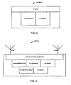
Figure 2 illustrates selected components of an exemplary embodiment of theradio network controller 110. As shown inFigure 2 , theradio network controller 110 includes aBTS interface 111 to enable theRNC 110 to communicate with theBTSs processor 112, and amemory device 113 storing computer code instructions. Theprocessor 112 is coupled to thememory device 113 and to theBTS interface 111, so that theprocessor 112 reads and executes the code stored in thememory device 113, configuring theBTS interface 111 to cause theBTSs UE 140 and other UEs using the processes described throughout this document. - The radio network may include additional controllers.
-
Figure 3 illustrates selected components of an exemplary embodiment of theUE 140. As shown inFigure 3 , theUE 140 includes receiveantennae decoder block 144, a user input device (e.g., a keypad) 145, a display (e.g., an LCD screen) 146, aprocessor 147, and amemory device 148. Theradio network transceiver 143, encoder anddecoder block 144, user input device 145, and display 146 are configured by theprocessor 147 under control of the code stored in thememory device 148. Theuser equipment device 140 is configured to communicate with theradio network 105 over wireless communication links using a wireless cellular network transmission protocol, such as the cellular packet transmission protocols described above, and to execute processes described throughout this document. - Additional UEs may be in communication with the
radio network 105. - The radio network may also include additional base transceiver stations.
- The
radio network 105 may transmit to theUE 140 using Orthogonal Frequency Division Multiplexing (OFDM). In each Orthogonal Frequency Division Multiplexing symbol (sub-carrier), each stream may be transmitted from theradio network 105 to theUE 140 on a separate antenna; further, the mapping of stream ID to transmit antenna ID is permuted in time, so that the Rx SNR for each stream is approximately identical. - Without any loss in generality, let us assume a relatively simple scenario for this case, wherein:

- To enable accurate channel estimation for each Tx-Rx antenna pair, the pilot sub-carriers are not re-used across Tx antennae. This is unlike data sub-carrier indices, which are re-used across all Tx antennae. Therefore, the following holds:

wherein Pi ∈ Set of pilot sub-carrier indices on antenna i. - The Rx symbol for a given OFDM symbol can be written as shown below:

wherein - Xj [k] = Pre-IFFT Tx modulation symbol on antenna j on sub-carrier k,
- Hij [k] = Channel frequency response on sub - carrier k from cell i and antenna j,
- Cj [k] = SFN channel frequency response on sub-carrier k and antenna j,
- Y[k] = Post - FFT Rx symbol on sub - carrier k, and
- Hij [k], Cj [k], Y[k] = NR ×1 vectors.
- Noting that the pilots from each antenna are orthogonal in frequency domain, we have this relationship:

- The composite SFN channel frequency response for each Tx antenna can be estimated using, for example, a Minimum Mean Square Error (MMSE) or low complexity zero-forced Robust MMSE solution.
- After channel estimation, stream separation and inter-stream interference suppression may be achieved using a MMSE filter. This can be written by invoking the Orthogonal Projection Lemma, as follows:


wherein
- After stream separation at the receiver, each stream may be independently decoded, and then successively canceled out from all other streams. Cancellation steps may be iterated until all streams are decoded. The complexity of successive interference cancellation (SIC) depends on the number of streams.
- On the receiving side, the receiver (such as the UE 140) receives a first signal using a first receive antenna, and a second signal using a second receive antenna. The first signal includes a first data stream transmitted through a first physical channel from a first transmit antenna or a first set of transmitter antennae, and a second data stream transmitted through a second physical channel from a second transmit antenna or a second set of transmit antennae. Similarly, the second signal includes the first data stream transmitted through a third physical channel, and the second data stream transmitted through a fourth physical channel. The four channels are estimated, for example, using pilot channels at the receiver, or at the radio network with data provided by the receiver. The first and second data streams can then be separated by the receiver to obtain a first separated data stream and a second separated data stream. After separation, the receiver attempts to decode first data in the first data stream and second data in the second data stream. If the first attempt to decode the data is not successful, the receiver may attempt to decode again after cancelling the interference based on the partial decoding obtained during the first attempt.
- The first and the second data streams may be multicast or broadcast on common channel(s).
- Because open loop broadcast and multicast transmissions are generally targeted to the worst case receiver, successive interference cancellation may be omitted if not all targeted UEs implement this step.
- The discussion so far described an embodiment of
Figure 1 in which SFN spectral efficiency of an OFDM system is enhanced through MIMO technique, using multiple antennae at a cell, i.e., S = NT ≥ 2. The operation of the embodiment ofFigure 1 is not necessarily limited to the use of OFDM, but may employ other methods using MIMO. - As noted in the BACKGROUND section of this document, many cells (sectors) have a single transmit antenna. Adding transmit antennae to sites involves additional costs that operators would rather avoid. Consequently, in other embodiments we do not assume transmit diversity from a single cell. Instead, we assume that:

- NT = 1 (i.e., one transmit antenna per cell).
- In other words, we assign transmit antennae into sets, and transmit different data streams from different sets, one stream per one set of transmit antennae.
- Here, the SNR may be lower than in the strict SNF operation where all cells transmit the same stream, because each stream may be transmitted from a partial subset of the network's cells. Nevertheless, it is likely that the SNR is still high enough to exploit spatial multiplexing gains. This is particularly so if the number of such sets/streams is small and, consequently, the number of transmit antennae in each set is relatively large, providing good coverage throughout the geographic area of interest.
- In such arrangement a problem arises for those UEs that are situated in the interior of one of the cells, because these Us have a high carrier-to-interference (C/I) ratio based on a strong signal from one cell only. Such UEs do not benefit from spatial multiplexing, but can rely on other multiplexing techniques, e.g., temporal multiplexing (TDM) and frequency multiplexing.
-
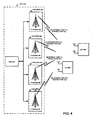
Figure 4 illustrates a singlefrequency radio network 405 using TDM and MIMO to broadcast or multicast toUEs radio network 405 includes aradio network controller 410 and cells/BTSs antennae radio network controller 410 may be similar or identical to the structure of theradio network controller 110. The structure of each of theUEs 440A/B may also be the same as or similar to the structure of theUE 140. Here, however, theradio network 405 and theUEs 440A/B are configured to communicate in accordance with the methods described below in relation to this embodiment. - In this embodiment, S = NR , a generic PRAP or Code Re-use BLAST (CR-BLAST) scheme is used, and NR streams are transmitted from

- In this case, multiple streams are multiplexed in a time division multiplexed manner on a single transmit antenna per cell. In a two stream scenario, for example, half the symbols per slot may be dedicated to one stream, and the other half of the symbols are dedicated to the second stream. During a first period of time (T1), for example, a first stream of symbols is transmitted from a first set of transmit antennae that includes the transmit
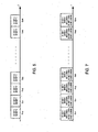
antennae BTSs 424 and 432, while a second stream of symbols is transmitted from a second set of transmit antennae that includes transmitantennae BTSs Figure 5 , which shows time periods T1-1 through T1-N during which the radio network transmits the first stream from the first set, and the second stream from the second set; similarly, the radio network transmits the first stream from the second set and the second stream from the first set during time periods T2-1 through T2-N. - Those UEs that are sufficiently far from each of the transmit antennae, such as the
UE 440A, benefit from the spatial multiplexing gains resulting from the use of MIMO. In other words, theUE 440A receives both symbol streams. At the same time, the UEs in cell interiors, such as theUE 440B, benefit from temporal multiplexing and high C/I. In other words, theUE 440B may receive only one of the streams at a time, but with a relatively high C/I ratio and concomitantly high SNR, particularly in view of the proximity of theUE 440B to a transmit antenna. - After stream separation, each stream may be independently decoded, and then successively canceled out from all other streams. Cancellation steps may be iterated until all streams are decoded. The complexity of successive interference cancellation (SIC) depends on the number of streams.
- The receiver of this embodiment may receive, during one or more first time periods, a first signal using a first receive antenna, and a second signal using a second receive antenna. The first signal includes (1) a first data stream transmitted through a first physical channel from a first transmit antenna or a first set of transmit antennae, and (2) a second data stream transmitted through a second physical channel from a second transmit antenna or a second set of transmit antennae. Similarly, the second signal includes the first data stream transmitted through a third physical channel, and the second data stream transmitted through a fourth physical channel. The first data stream carries first data during the first time period(s), and the second data stream carries second data during the first time period(s).
- The four channels are estimated, for example, using pilot channels at the receiver. The first and second data streams can then be separated by the receiver to obtain a first separated data stream and a second separated data stream. After separation, the receiver attempts to decode the first data in the first data stream and the second data in the second data stream.
- If the first attempt to decode the data is not successful, the receiver may attempt to decode again after cancelling the interference based on the partial decoding obtained during the first attempt.
- The receiver may also attempt to decode the data from the signals received during subsequent time period or periods. Thus, if the first attempt to decode is not successful, the receiver may receive at the first antenna the first signal during one or more second time periods, and receive at the second antenna the second signal during the one or more second time periods. The receiver may separate the first and second data streams from at least one of the first signal and the second signal using some or all of the channel estimates, to obtain first separated data stream and second separated data stream of the second time periods. After the streams are separated, the receiver may again attempt to decode the first and the second data from the first and second separated data streams of the first and second time periods.
- Recall that, because of the use of TDM, the first signal during the second periods includes the second data stream transmitted through the first physical channel and the first data stream transmitted through the second physical channel, and the second signal includes the second data stream transmitted through the third physical channel and the first data stream transmitted through the fourth physical channel. Recall also that the first data stream carries the first data during the second time periods, and the second data stream carries the second data during the second time periods. Thus, the data may be transmitted redundantly during the first and second time period(s).
- The first and the second data streams may be multicast or broadcast on common channel(s).
-
Figure 6 illustrates a singlefrequency radio network 605 using Hierarchical Modulation (HM) and MIMO to broadcast or multicast toUEs 640A and 640B. Theradio network 605, which is similar to thenetwork 405 ofFigure 4 , includes aradio network controller 610 and cells/BTSs antennae radio network controller 610 may be similar or identical to the structure of theradio network controller 110, which is shown inFigure 2 . The structure of each of theUEs 640A/B may also be the same as or similar to the structure of theUE 140, which is shown inFigure 3 . The radio network and theUEs 640A/B are configured to communicate in accordance with the methods described below in relation to this embodiment. - Here, as in the
network 405, S = NR, a generic PRAP or Code Re-use BLAST (CR-BLAST) scheme is used, and NR streams are transmitted from cells at any given time. The streams are carried by hierarchically modulated signals. - In hierarchical modulation, a carrier is encoded with two data flows. Considering 64-QAM (Quadrature Amplitude Modulation), data is mapped so that there is a QPSK flow contained in the 64-QAM. This results in two data flows: the QPSK data flow and a 16-QAM data flow. The combined data rate of the two data flows may be the same as the data rate of the corresponding 64-QAM data flow. For the QPSK data flow, symbols are encoded onto a carrier so that different sections in the complex signal plane of the modulation constellation (such as the Q-I plane) represent different positions of the symbol alphabet bits. For example, the left part of the Q-I plane may correspond to the "1" value of the most significant bit of a symbol, and the right half of the plane may correspond to the "0" value of this bit. Similarly, the lower half of the plane may correspond to the "1" value of the second most significant bit position, and the top half of the plane may correspond to the "0" value of this bit. Thus, a symbol falling in the top left quadrant would represent "10" in the two most significant bit positions, a symbol in the top right quadrant would represent "00" in these positions, and symbols in the bottom left and bottom right quadrants would represent "11" and "01" values, respectively. Additional bits of the symbol corresponding to the 16-QAM data flow are determined by the symbol's position within the particular quadrant determined by the first two bits.
- Note that the QPSK data flow is more robust than the 16-QAM data flow, meaning that the QPSK data flow may be decoded at lower SNR and lower C/I ratios of the signal. Spacing within the constellation may be varied to provide additional robustness to the QPSK data flow at the cost of the 16-QAM data flow. Thus, the more-robust BPSK data flow has a greater coverage than the less-robust 16-QAM data flow.
- In this document, the more robust layer of a hierarchically modulated signal (such as the BPSK stream in the 64-QAM example above) will be referred to as the base layer; the less robust layer of the hierarchically modulated signal (such as the 16-QAM stream of the 64-QAM example) will be referred to as the enhancement layer.
- Hierarchical modulation provides a mechanism for increasing transmission capacity. The capacity increase comes at the expense of reduced coverage for enhancement layer, while the base layer performance is improved.
- In the
SNF 605, the stream mapping may be permuted in time from base to enhancement layers. During the first time periods T1 ofFigure 7 , for example, a first data stream S1 may be transmitted from the first set of antennae on the base layer of a first hierarchically modulated signal and, concurrently, from the second set of antennae on the enhancement layer of a second hierarchically modulated signal. During the second time periods T2 ofFigure 5 , the first data stream may be transmitted from the first set of antennae on the enhancement layer of the first hierarchically modulated signal and, concurrently, from the second set of antennae on the base layer of the second hierarchically modulated signal. Thus, when the first stream is transmitted on the base layer of a set of antennae, the second layer is transmitted on the enhancement layer of the same set, and vice versa. In other words:
- i = Stream ID; and
- n . = OFDM symbol index.
- As in the TDM embodiment of
Figure 4 , data in each stream may be redundantly transmitted during successive time periods. - A receiver (one of the
UEs 640, for example) may be configured to receive at a first receive antenna a first receive signal that includes (1) the first signal component transmitted from a first transmit antenna (or a first set of transmit antennae) through a first physical channel, and (2) a second signal component transmitted from a second transmit antenna (or a second set of transmit antennae) through a second physical channel. The first signal component may include (1) a first base layer carrying a first data stream, and (2) a first enhancement layer carrying a second data stream; the second signal component may include (1) a second base layer carrying the second data stream, and (2) a second enhancement layer carrying the first data stream. The receiver may be further configured to receive at a second antenna a second signal that includes (1) a third signal component transmitted through a third physical channel, and (2) a fourth signal component transmitted through a fourth physical channel. The third signal component may include (1) a third base layer carrying the first data stream, and (2) a third enhancement layer carrying the second data stream; the fourth signal component may include (1) a fourth base layer carrying the second data stream, and (2) a fourth enhancement layer carrying the first data stream. - The first, second, third, and fourth physical channels may be estimated to obtain channel estimates for the channels. Channel estimation may be performed by the receiver and be based on pilot channels. After some or all the channel estimates become available, the receiver may separate the first and second signal components. After the signal separation, the receiver may attempt to decode the first data stream from the first base layer and the second data stream from the first enhancement layer.
- The receiver may attempt to decode the second data stream from both the first enhancement layer and the second base layer. Alternatively, the receiver may estimate the quality of the first signal and, if the quality of the first signal (e.g., SNR) is higher than a predetermined measure, decode the second data stream from the first enhancement layer; if the quality of the first signal does not exceed the measure, the receiver may separate the third and fourth signal components using the channel estimates, and attempt decode the second data stream from the second base layer. The receiver may also estimate the quality of the second signal and, if the quality of the second signal is below a predetermined threshold, attempt to decode the second data stream from the first enhancement layer; if the quality of the second signal is not below the threshold, the receiver may separate the third and fourth signal components and attempt to decode the second data stream from the second base layer.
- Interference Cancellation (IC) techniques may be used to cancel the interference from base layer to enhancement layer of the same signal.
- In case multiple transmit antennae are present at the Node-B and cell-specific content needs to be transmitted, the system can switch to Space Time Transmit Diversity (STTD), or turn off the transmit diversity antennae. The first of these options may be simpler with no RF implications of dynamic switching on/off the transmit diversity antennae.
- Although steps of the various methods have been described serially in this disclosure, some of these steps may be performed by separate elements in conjunction or in parallel, asynchronously or synchronously, in a pipelined manner, or otherwise. There is no particular requirement that the steps be performed in the same order in which this description lists them, except where explicitly so indicated, otherwise made clear from the context, or inherently required. Furthermore, not every illustrated step or communication message is necessarily required in every embodiment in accordance with the invention, while some steps or communication messages that have not been specifically illustrated may be desirable in some embodiments in accordance with the invention.
- Those of skill in the art would understand that information and signals may be represented using any of a variety of different technologies and techniques. For example, data, instructions, commands, information, signals, bits, symbols, and chips that may be referenced throughout the above description may be represented by voltages, currents, electromagnetic waves, magnetic fields or particles, optical fields or particles, or any combination thereof.
- Those of skill would further appreciate that the various illustrative logical blocks, modules, circuits, and algorithm steps described in connection with the embodiments disclosed herein may be implemented as electronic hardware, computer software, or combinations of both. To clearly illustrate this interchangeability of hardware and software, various illustrative components, blocks, modules, circuits, and steps have been described above generally in terms of their functionality. Whether such functionality is implemented as hardware, software, or combination of hardware and software depends upon the particular application and design constraints imposed on the overall system. Skilled artisans may implement the described functionality in varying ways for each particular application, but such implementation decisions should not be interpreted as causing a departure from the scope of the present invention.
- The various illustrative logical blocks, modules, and circuits described in connection with the embodiments disclosed herein may be implemented or performed with a general purpose processor, a digital signal processor (DSP), an application specific integrated circuit (ASIC), a field programmable gate array (FPGA) or other programmable logic device, discrete gate or transistor logic, discrete hardware components, or any combination thereof designed to perform the functions described herein. A general purpose processor may be a microprocessor, but in the alternative, the processor may be any conventional processor, controller, microcontroller, or state machine. A processor may also be implemented as a combination of computing devices, e.g., a combination of a DSP and a microprocessor, a plurality of microprocessors, one or more microprocessors in conjunction with a DSP core, or any other such configuration.
- The steps of methods or algorithms described in connection with the embodiments disclosed herein may be embodied directly in hardware, in a software module executed by a processor, or in a combination of the two. A software module may reside in random access memory (RAM), flash memory, read only memory (ROM), erasable programmable read only memory (EPROM), electrically erasable programmable read only memory (EEPROM), registers, hard disk, removable disk, CD-ROM, or any other form of storage medium known in the art. An exemplary storage medium is coupled to the processor such that the processor can read information from, and write information to, the storage medium. In the alternative, the storage medium may be integral to the processor. The processor and the storage medium may reside in an ASIC. The ASIC may reside in a user equipment device. Alternatively, the processor and the storage medium may reside as discrete components in a user equipment device.
- The previous description of the disclosed embodiments is provided to enable any person skilled in the art to make or use the present invention. Various modifications to these embodiments will be readily apparent to those skilled in the art, and the generic principles defined herein may be applied to other embodiments. Thus, the present invention is not intended to be limited to the embodiments shown herein.
Claims (22)
- A method of transmitting data from a plurality of sectors in a cellular communication system, the method comprising:assigning at least one transmit antenna (421, 425, 429, 433) from each sector of the plurality of sectors to a transmit antenna set of a plurality of L transmit antenna sets, L being an integer greater than 1, each transmit antenna set of the plurality of L transmit antenna sets comprising at least one transmit antenna of the cellular communication system;arranging the data into a plurality of L data streams;assigning, for at least one first period, each data stream of the plurality of L data streams to a different transmit antenna set of the L transmit antenna sets, resulting in a first distribution of data streams among transmit antenna sets;for said each transmit antenna set of the plurality of L transmit antenna sets, modulating, during the at least one first period, a carrier of a first frequency with the data stream assigned to said each transmit antenna set during the at least one first period; andtransmitting to a plurality of receivers (440A, 440B) during the at least one first period the carrier through the transmit antennae of the plurality of L transmit antenna sets so that transmit antennae of said each transmit antenna set transmit during the at least one first period the data stream assigned to said each transmit antenna set for the at least one first period; and further comprising:assigning, for at least one second period, said each data stream to a different transmit antenna set of the L transmit antenna sets, resulting in a second distribution of data streams among transmit antenna sets, the second distribution being different from the first distribution;for said each transmit antenna set of the plurality of L transmit antenna sets, modulating, during the at least one second period, the carrier with the data stream assigned to said each transmit antenna set during the at least one second period; andtransmitting to the plurality of receivers during the at least one second period the carrier through the transmit antennae of the plurality of L transmit antenna sets so that transmit antennae of said each transmit antenna set transmit during the at least one second period the data stream assigned to said each transmit antenna set for the at least one second period.
- The method of claim 1, wherein the plurality of L antenna sets comprises a first transmit antenna and a second transmit antenna, the first transmit antenna being in a first sector of the cellular communication system, the first antenna being the only transmit antenna of the cellular communication system in the first sector configured to transmit using the first frequency.
- The method of claim 2, wherein the second antenna is in a second sector of the cellular communication system, the second antenna being the only transmit antenna of the cellular communication system in the second sector configured to transmit using the first frequency.
- The method of claim 1, wherein:L is equal to two;the at least one first period comprises a plurality of first periods;the at least one second period comprises a plurality of second periods; andduring a first time duration the first periods of the plurality of first periods are interleaved with the second periods of the plurality of second periods.
- The method of claim 1, wherein:the plurality of L transmit antenna sets comprises a first transmit antenna set; andthe first transmit antenna set comprises a first antenna from a first sector and a second antenna from a second sector.
- A radio network controller for a cellular communication system comprising a plurality of sectors, each sector comprising at least one transmit antenna (421, 425, 429, 433) and at least one base transceiver station (420, 424, 428, 432), wherein the radio network controller (410) is configured to perform operations comprising:assigning at least one transmit antenna from each sector of the plurality of sectors to a transmit antenna set of a plurality of L transmit antenna sets, L being an integer greater than 1, each transmit antenna set of the plurality of L transmit antenna sets comprising at least one transmit antenna of the cellular communication system;arranging data into a plurality of L data streams;assigning for at least one first period, each data stream of the plurality of L data streams to a different transmit antenna set of the L transmit antenna sets, resulting in a first distribution of data streams among transmit antenna sets;for said each transmit antenna set of the plurality of L transmit antenna sets, causing the plurality of sectors to modulate, during the at least one first period, a carrier of a first frequency with the data stream assigned to said each transmit antenna set during the at least one first period; andcausing the plurality of sectors to transmit to a plurality of receivers during the at least one first period the carrier through the transmit antennae of the plurality of L transmit antenna sets so that transmit antennae of said each transmit antenna set transmit during the at least one first period the data stream assigned to said each transmit antenna set for the at least one first period; and characterized byassigning, for at least one second period, said each data stream to a different transmit antenna set of the L transmit antenna sets, resulting in a second distribution of data streams among transmit antenna sets, the second distribution being different from the first distribution;for said each transmit antenna set of the plurality of L transmit antenna sets, causing the plurality of sectors to modulate, during the at least one second period, the carrier with the data stream assigned to said each transmit antenna set during the at least one second period; andcausing the plurality of sectors to transmit to the plurality of receivers during the at least one second period the carrier through the transmit antennae of the plurality of L transmit antenna sets so that transmit antennae of said each transmit antenna set transmit during the at least one second period the data stream assigned to said each transmit antenna set for the at least one second period.
- The radio network controller of claim 6, wherein the plurality of L antenna sets comprises a first transmit antenna and a second transmit antenna, the first transmit antenna being in a first sector of the cellular communication system, the first antenna being the only transmit antenna of the cellular communication system in the first sector configured to transmit using the first frequency.
- The radio network controller of claim 7, wherein the second antenna is in a second sector of the cellular communication system, the second antenna being the only transmit antenna of the cellular communication system in the second sector configured to transmit using the first frequency.
- A machine-readable medium comprising instructions, the instructions, when executed by at least one processor of a radio network controller (410) for a cellular communication system comprising a plurality of sectors, each sector comprising at least one transmit antenna (421, 425, 429, 433), configure the radio network controller to perform operations comprising:assigning at least one transmit antenna from each sector of the plurality of sectors to a transmit antenna set of a plurality of L transmit antenna sets, L being an integer greater than 1, each transmit antenna set of the plurality of L transmit antenna sets comprising at least one transmit antenna of the cellular communication system;arranging data into a plurality of L data streams;assigning, for at least one first period, each data stream of the plurality of L data streams to a different transmit antenna set of the L transmit antenna sets, resulting in a first distribution of data streams among transmit antenna sets;for said each transmit antenna set of the plurality of L transmit antenna sets, causing the plurality of sectors to modulate, during the at least one first period, a carrier of a first frequency with the data stream assigned to said each transmit antenna set during the at least one first period; andcausing the plurality of sectors to transmit to a plurality of receivers during the at least one first period the carrier through the transmit antennae of the plurality of L transmit antenna sets so that transmit antennae of said each transmit antenna set transmit during the at least one first period the data stream assigned to said each transmit antenna set for the at least one first period; and characterized byassigning, for at least one second period, said each data stream to a different transmit antenna set of the L transmit antenna sets, resulting in a second distribution of data streams among transmit antenna sets, the second distribution being different from the first distribution;for said each transmit antenna set of the plurality of L transmit antenna sets, causing the plurality of sectors to modulate, during the at least one second period, the carrier with the data stream assigned to said each transmit antenna set during the at least one second period; andcausing the plurality of sectors to transmit to the plurality of receivers during the at least one second period the carrier through the transmit antennae of the plurality of L transmit antenna sets so that transmit antennae of said each transmit antenna set transmit during the at least one second period the data stream assigned to said each transmit antenna set for the at least one second period.
- A method of transmitting data from a plurality of sectors in a cellular communication system, the method comprising:assigning at least one transmit antenna (621, 625, 629, 633) of each sector of the plurality of sectors into a first transmit antenna set or a second transmit antenna set, each antenna set of the first and second transmit antenna sets comprising at least one transmit antenna;arranging the data into a first data stream and a second data stream;hierarchically modulating a carrier of a given frequency to obtain a first signal having a first base layer and a first enhancement layer;hierarchically modulating the carrier to obtain a second signal having a second base layer and a second enhancement layer;transmitting the first signal through each transmit antenna in the first transmit antenna set; andtransmitting the second signal through each antenna in the second transmit antenna set;wherein the steps of hierarchically modulating are performed so that the first base layer carries information of the first data stream, the first enhancement layer carries information of the second data stream, the second base layer carries information of the second data stream, and the second enhancement layer carries information of the first data stream.
- The method of claim 10, wherein the step of transmitting the first hierarchically modulated carrier comprises broadcasting or multicasting.
- A radio network controller (610) for a cellular communication system comprising a plurality of sectors, each sector comprising at least one transmit antenna (621, 625, 629, 633), wherein the radio network controller is configured to perform operations comprising:assigning the at least one transmit antenna of each sector of the plurality of sectors into a first transmit antenna set or a second transmit antenna set, each antenna set of the first and second transmit antenna sets comprising at least one transmit antenna;arranging data into a first data stream and a second data stream;causing hierarchical modulation of a carrier of a given frequency to obtain a first signal having a first base layer and a first enhancement layer;causing hierarchical modulation of the carrier to obtain a second signal having a second base layer and a second enhancement layer;causing transmission of the first signal through each transmit antenna in the first transmit antenna set; andcausing transmission of the second signal through each transmit antenna the second transmit antenna set;wherein the first base layer carries information of the first data stream, the first enhancement layer carries information of the second data stream, the second base layer carries information of the second data stream, and the second enhancement layer carries information of the first data stream.
- A machine-readable medium comprising instructions, the instructions, when executed by at least one processor of a radio network controller for a cellular (610) communication system comprising a plurality of sectors, each sector comprising at least one transmit antenna (621, 625, 629, 633), configure the radio network controller to perform operations comprising:assigning the at least one transmit antenna of each sector of the plurality of sectors into a first transmit antenna set or a second transmit antenna set, each antenna set of the first and second transmit antenna sets comprising at least one transmit antenna;arranging data into a first data stream and a second data stream;causing hierarchical modulation of a carrier of a given frequency to obtain a first signal having a first base layer and a first enhancement layer,causing hierarchical modulation of the carrier to obtain a second signal having a second base layer and a second enhancement layer,causing transmission of the first signal through each transmit antenna in the first transmit antenna set; andcausing transmission of the second signal through each transmit antenna the second transmit antenna set;wherein the first base layer carries information of the first data stream, the first enhancement layer carries information of the second data stream, the second base layer carries information of the second data stream, and the second enhancement layer carries information of the first data stream.
- A cellular communication system comprising a wireless user equipment device (440A, 440B) for communicating with a base transceiver station, and radio network controller according to claim 6, the wireless user equipment device comprising:a first antenna and a second antenna;a receiver coupled to the first and second antennae;a memory storing program code; anda processor coupled to the receiver and to the memory;wherein:the receiver is configured to:receive at its first antenna a first signal during a first time period and a second time period, the first signal being carried on a first frequency, the first signal comprising, during the first time period, a first data stream transmitted through a first physical channel and a second data stream transmitted through a second physical channel and, during the second time period, the first data stream transmitted through the second physical channel and the second data stream transmitted through the first physical channel, andreceive at its second antenna a second signal during the first and second time periods, the second signal being carried on the first frequency, the second signal comprising, during the first time period, the first data stream transmitted through a third physical channel and the second data stream transmitted through a fourth physical channel and, during the second time period, the first data stream transmitted though the fourth physical channel and the second data stream transmitted through the third physical channel; andthe processor of the wireless user equipment device is configured to perform operations comprising:estimating the first physical channel to obtain one or more first channel estimates,estimating the second physical channel to obtain one or more second channel estimates,estimating the third physical channel to obtain one or more third channel estimates,estimating the fourth physical channel to obtain one or more fourth channel estimates, andseparating the first and second data streams from at least one of the first signal and the second signal using at least some of the one or more first, second, third, and fourth channel estimates, resulting in first separated data stream and second separated stream of the first and second time periods.
- The system of claim 14, wherein the processor of the wireless user equipment device is further configured to first attempt to decode first and the second data from the first and second separated data streams of the first and second time periods.
- The system of claim 15, wherein:the receiver of the wireless user equipment device is further configured to:receive at the first antenna of the wireless user equipment device the first signal during third time period, the first signal comprising the second data stream transmitted through the first physical channel and the first data stream transmitted through the second physical channel, the first data stream comprising the first data during the third time period, the second data stream comprising the second data during the third time period, andreceive at the second antenna of the wireless user equipment device the second signal during the third time period, the second signal comprising the second data stream transmitted through the third physical channel and the first data stream transmitted through the fourth physical channel; andthe processor of the wireless user equipment device is further configured, if the first attempting to decode is not successful, to perform operations comprising:separating the first and second data streams from at least one of the first signal and the second signal using at least some of the one or more first, second, third, and fourth channel estimates, resulting in first separated data stream and second separated data stream of the third time period, andsecond attempting to decode the first and the second data from the first and second separated data streams of the third time period.
- A method of receiving data sent from a cellular communication system, the method comprising:receiving at a first antenna a first signal, the first signal comprising a first signal component transmitted through a first physical channel and a second signal component transmitted through a second physical channel, the first signal component comprising a first base layer carrying a first data stream and a first enhancement layer carrying a second data stream, the second signal component comprising a second base layer carrying the second data stream and a second enhancement layer carrying the first data stream;receiving at a second antenna a second signal, the second signal comprising a third signal component transmitted through a third physical channel and a fourth signal component transmitted through a fourth physical channel, the third signal component comprising a third base layer carrying the first data stream and a third enhancement layer carrying the second data stream, the fourth signal component comprising a fourth base layer carrying the second data stream and a fourth enhancement layer carrying the first data stream;estimating the first, second, third, and fourth physical channels to obtain one or more channel estimates;separating the first and second signal components using the one or more channel estimates;decoding the first data stream from the first base layer after the step of separating; anddecoding the second data stream from at least one layer selected from the first enhancement layer and the second base layer, after the step of separating;wherein the first, second, third, and fourth signal components are hierarchically modulated using the same carrier frequency.
- The method of claim 17, wherein the step of decoding the second data stream comprises decoding the second data stream from both the first enhancement layer and the second base layer.
- The method of claim 17, wherein the step of receiving at the first antenna comprises receiving on a common channel.
- The method of claim 17, wherein the step of receiving at the first antenna comprises receiving a broadcast or a multicast.
- A wireless user equipment device (640A, 640B) for communicating with a base transceiver station of a radio network, the wireless user equipment device comprising:a first antenna and a second antenna;a receiver,a memory storing program code; anda processor coupled to the receiver and to the memory;wherein:the receiver is configured to:receive at the first antenna a first signal, the first signal comprising a first signal component transmitted through a first physical channel and a second signal component transmitted through a second physical channel, the first signal component comprising a first base layer carrying a first data stream and a first enhancement layer carrying a second data stream, the second signal component comprising a second base layer carrying the second data stream and a second enhancement layer carrying the first data stream, andreceive at the second antenna a second signal, the second signal comprising a third signal component transmitted through a third physical channel and a fourth signal component transmitted through a fourth physical channel, the third signal component comprising a third base layer carrying the first data stream and a third enhancement layer carrying the second data stream, the fourth signal component comprising a fourth base layer carrying the second data stream and a fourth enhancement layer carrying the first data stream;the processor is configured to:estimate the first, second, third, and fourth physical channels to obtain one or more channel estimates,separate the first and second signal components using the one or more channel estimates,after separating, decode the first data stream from the first base layer, andafter separating, decode the second data stream from at least one layer selected from the first enhancement layer and the second base layer, andthe first, second, third, and fourth signal components are hierarchically modulated using the same carrier frequency.
- A machine-readable medium comprising instructions, the instructions, when executed by at least one processor of a wireless user equipment device, (640A, 640B) cause the wireless user equipment device to perform operations comprising:receiving at a first antenna a first signal, the first signal comprising a first signal component transmitted through a first physical channel and a second signal component transmitted through a second physical channel, the first signal component comprising a first base layer carrying a first data stream and a first enhancement layer carrying a second data stream, the second signal component comprising a second base layer carrying the second data stream and a second enhancement layer carrying the first data stream;receiving at a second antenna a second signal, the second signal comprising a third signal component transmitted through a third physical channel and a fourth signal component transmitted through a fourth physical channel, the third signal component comprising a third base layer carrying the first data stream and a third enhancement layer carrying the second data stream, the fourth signal component comprising a fourth base layer carrying the second data stream and a fourth enhancement layer carrying the first data stream;estimating the first, second, third, and fourth physical channels to obtain one or more channel estimates;separating the first and second signal components using the one or more channel estimates;decoding the first data stream from the first base layer after the step of separating; anddecoding the second data stream from at least one layer selected from the first enhancement layer and the second base layer, after the step of separating;wherein the first, second, third, and fourth signal components are hierarchically modulated using the same carrier frequency.
Priority Applications (1)
| Application Number | Priority Date | Filing Date | Title |
|---|---|---|---|
| EP10168349A EP2228915A3 (en) | 2005-06-14 | 2006-06-09 | Transmit spatialdiversity for cellular single frequency networks |
Applications Claiming Priority (3)
| Application Number | Priority Date | Filing Date | Title |
|---|---|---|---|
| US69062205P | 2005-06-14 | 2005-06-14 | |
| US11/450,229 US8059608B2 (en) | 2005-06-14 | 2006-06-08 | Transmit spatial diversity for cellular single frequency networks |
| PCT/US2006/022725 WO2006138203A1 (en) | 2005-06-14 | 2006-06-09 | Transmit spatial diversity for cellular single frequency networks |
Related Child Applications (2)
| Application Number | Title | Priority Date | Filing Date |
|---|---|---|---|
| EP10168349A Division-Into EP2228915A3 (en) | 2005-06-14 | 2006-06-09 | Transmit spatialdiversity for cellular single frequency networks |
| EP11184393 Division-Into | 2011-10-07 |
Publications (2)
| Publication Number | Publication Date |
|---|---|
| EP1894317A1 EP1894317A1 (en) | 2008-03-05 |
| EP1894317B1 true EP1894317B1 (en) | 2014-04-23 |
Family
ID=37524096
Family Applications (2)
| Application Number | Title | Priority Date | Filing Date |
|---|---|---|---|
| EP10168349A Withdrawn EP2228915A3 (en) | 2005-06-14 | 2006-06-09 | Transmit spatialdiversity for cellular single frequency networks |
| EP06760742.4A Active EP1894317B1 (en) | 2005-06-14 | 2006-06-09 | Transmit spatial diversity for cellular single frequency networks |
Family Applications Before (1)
| Application Number | Title | Priority Date | Filing Date |
|---|---|---|---|
| EP10168349A Withdrawn EP2228915A3 (en) | 2005-06-14 | 2006-06-09 | Transmit spatialdiversity for cellular single frequency networks |
Country Status (6)
| Country | Link |
|---|---|
| US (2) | US8059608B2 (en) |
| EP (2) | EP2228915A3 (en) |
| JP (4) | JP2008547267A (en) |
| KR (1) | KR100942652B1 (en) |
| CN (1) | CN102684764B (en) |
| WO (1) | WO2006138203A1 (en) |
Families Citing this family (65)
| Publication number | Priority date | Publication date | Assignee | Title |
|---|---|---|---|---|
| US8059608B2 (en) * | 2005-06-14 | 2011-11-15 | Qualcomm Incorporated | Transmit spatial diversity for cellular single frequency networks |
| US8072943B2 (en) * | 2005-12-09 | 2011-12-06 | Samsung Electronics Co., Ltd. | Wireless communication system and methodology for communicating via multiple information streams |
| KR100961743B1 (en) * | 2005-12-09 | 2010-06-07 | 삼성전자주식회사 | Apparatus and method for supporting relay service in multi-hop relay broadband wireless access communication system |
| US7965687B2 (en) * | 2005-12-15 | 2011-06-21 | Sasken Communications Technologies | Method and system for multiple-input-multiple-output (MIMO) communication in a wireless network |
| US8781391B2 (en) * | 2006-07-27 | 2014-07-15 | Telefonaktiebolaget Lm Ericsson | Hierarchical broadcast transmission via multiple transmitters |
| KR100881619B1 (en) * | 2006-08-28 | 2009-02-04 | 삼성전자주식회사 | Apparatus and method for receiving signal in broadband wireless access system |
| US8006029B2 (en) * | 2006-11-30 | 2011-08-23 | Intel Corporation | DDR flash implementation with direct register access to legacy flash functions |
| US8130875B2 (en) * | 2006-12-11 | 2012-03-06 | Cisco Technology, Inc. | Method for estimating channel response in a wireless communications network based on pilot signals |
| US8005160B2 (en) * | 2006-12-30 | 2011-08-23 | Nortel Networks Limited | Processing differentiated hierarchical modulation used in radio frequency communications |
| US8116412B1 (en) * | 2006-12-30 | 2012-02-14 | Rockstar Bidco, LP | Modulation division multiple access |
| US7986746B2 (en) * | 2006-12-30 | 2011-07-26 | Nortel Networks Limited | Content differentiated hierarchical modulation used in radio frequency communications |
| WO2008086415A1 (en) * | 2007-01-09 | 2008-07-17 | Viasat, Inc. | Multi-antenna satellite system with wireless interface to vehicle |
| JP4742113B2 (en) * | 2007-04-17 | 2011-08-10 | イノヴァティヴ ソニック リミテッド | MBMS reception method and apparatus in wireless communication system |
| US9185634B2 (en) * | 2007-04-17 | 2015-11-10 | Innovative Sonic Limited | Method and apparatus for enhancing receiving efficiency of an multimedia broadcast multicast service in a wireless communications system |
| CN103220785A (en) * | 2007-04-27 | 2013-07-24 | 交互数字技术公司 | A wireless transmit / receive unit and a method for the wireless transmit / receive unit |
| US20080298336A1 (en) * | 2007-05-31 | 2008-12-04 | Sridhar Gollamudi | macro-diversity technique for multicast transmission in a wireless communication system |
| KR101094441B1 (en) | 2007-06-20 | 2011-12-20 | 한국전자통신연구원 | Tramsmission Method, Transmission Apparatus, Reception Method and Reception Apparatus of Digital Broadcasting Signal |
| US8145272B2 (en) * | 2007-08-08 | 2012-03-27 | Cisco Technology, Inc. | Pilot-based two-dimensional channel estimation |
| US8229441B2 (en) * | 2007-08-24 | 2012-07-24 | Avaya Inc. | Graduated single frequency network |
| JP5042355B2 (en) * | 2007-10-03 | 2012-10-03 | エルジー エレクトロニクス インコーポレイティド | Transmission optimization method for broadcast and multicast services |
| EP2213073A4 (en) * | 2007-10-25 | 2011-10-19 | Ericsson Telefon Ab L M | A method of transmitting mbms data in an e-utran-system |
| CN101426207B (en) * | 2007-10-29 | 2011-11-16 | 中国移动通信集团公司 | Uni-frequency network controlling method and uni-frequency network controlling entity |
| CN101447854B (en) | 2007-11-27 | 2012-11-07 | 上海华为技术有限公司 | Data transmission/forwarding/processing method and device thereof |
| US8130823B2 (en) * | 2007-12-19 | 2012-03-06 | Broadcom Corporation | Channel adaptive video transmission system for use with layered video coding and methods for use therewith |
| WO2009119041A1 (en) * | 2008-03-26 | 2009-10-01 | パナソニック株式会社 | Wireless communication device, wireless communication system, and wireless communication method |
| US8724718B2 (en) * | 2008-04-10 | 2014-05-13 | Mediatek Inc. | Pilot pattern design for small size resource block in OFDMA systems |
| US20090257342A1 (en) * | 2008-04-10 | 2009-10-15 | Media Tek Inc. | Resource block based pilot pattern design for 1/2 - stream mimo ofdma systems |
| US8179983B2 (en) * | 2008-05-20 | 2012-05-15 | Broadcom Corporation | Video processing system with layered video coding for fast channel change and methods for use therewith |
| SG157971A1 (en) * | 2008-06-13 | 2010-01-29 | Panasonic Corp | A multiple-input multiple-output (mimo) transmitter and communication system |
| US8514693B2 (en) | 2008-07-11 | 2013-08-20 | Alcatel Lucent | Broadcast and multicast in single frequency networks using othrogonal space-time codes |
| US8249509B2 (en) * | 2008-11-24 | 2012-08-21 | Cisco Technology, Inc. | Dynamic channel estimation based on channel conditions |
| US20100150245A1 (en) * | 2008-12-15 | 2010-06-17 | Sony Ericsson Mobile Communications Ab | Multimedia Stream Selection |
| KR101013652B1 (en) * | 2008-12-30 | 2011-02-10 | 주식회사 세아네트웍스 | Method for transmitting signal in wireless communication system |
| US8953520B2 (en) * | 2009-02-13 | 2015-02-10 | Qualcomm Incorporated | Method and apparatus for inter-sector MIMO |
| JP5444374B2 (en) * | 2009-02-27 | 2014-03-19 | アルカテル−ルーセント | Cooperative beam forming method, cooperative beam forming apparatus, and cooperative beam forming base station |
| US20100304773A1 (en) * | 2009-05-27 | 2010-12-02 | Ramprashad Sean A | Method for selective antenna activation and per antenna or antenna group power assignments in cooperative signaling wireless mimo systems |
| US8908615B2 (en) * | 2009-07-01 | 2014-12-09 | Institute For Information Industry | Base station, relay station, computing apparatus, and reference signal transmission, allocation, and receiving methods thereof |
| US20110033011A1 (en) * | 2009-08-05 | 2011-02-10 | Industrial Technology Research Institute | Methods and apparatuses relating to multi-resolution transmissions with mimo scheme |
| KR101631477B1 (en) * | 2009-08-05 | 2016-06-17 | 삼성전자주식회사 | Communication system for adaptively using single-point trnasmission/reception and coordinated multi-point trnasmission/reception |
| US8902828B2 (en) | 2009-10-05 | 2014-12-02 | Qualcomm Incorporated | Carrier indicator field for cross carrier assignments |
| US8295335B2 (en) * | 2009-12-31 | 2012-10-23 | Intel Corporation | Techniques to control uplink power |
| CN101820669B (en) * | 2010-01-28 | 2012-11-14 | 北京邮电大学 | Method and device for allocating PDCCH resources |
| US20120076204A1 (en) * | 2010-09-23 | 2012-03-29 | Qualcomm Incorporated | Method and apparatus for scalable multimedia broadcast using a multi-carrier communication system |
| US10365969B2 (en) | 2011-11-01 | 2019-07-30 | International Business Machines Corporation | Multiple wireless communication systems stream slices based on geography |
| US9798616B2 (en) * | 2011-11-01 | 2017-10-24 | International Business Machines Corporation | Wireless sending a set of encoded data slices |
| US9609631B2 (en) * | 2012-01-20 | 2017-03-28 | Mediatek Inc. | Wireless communication apparatuses and related methods |
| US20130235783A1 (en) * | 2012-03-09 | 2013-09-12 | Qualcomm Incorporated | Evolved multimedia broadcast multicast service capacity enhancements |
| US8812039B2 (en) * | 2012-07-16 | 2014-08-19 | Telefonaktiebolaget L M Ericsson (Publ) | Method and system for reducing inter-cell interference using intra-ENB downlink coordinated multipoint services |
| US10863313B2 (en) | 2014-08-01 | 2020-12-08 | Polte Corporation | Network architecture and methods for location services |
| US10440512B2 (en) | 2012-08-03 | 2019-10-08 | Polte Corporation | Angle of arrival (AOA) positioning method and system for positional finding and tracking objects using reduced attenuation RF technology |
| US9337973B2 (en) | 2012-09-11 | 2016-05-10 | Industrial Technology Research Institute | Method of cooperative MIMO wireless communication and base station using the same |
| JP6788346B2 (en) * | 2012-10-01 | 2020-11-25 | ジーイー ビデオ コンプレッション エルエルシー | Scalable video coding using subpartition derivation of subblocks for prediction from the base layer |
| WO2014088654A1 (en) * | 2012-12-06 | 2014-06-12 | Intel Corporation | Sequence generation for cell specific reference signal (crs) |
| US9148325B2 (en) * | 2013-05-23 | 2015-09-29 | Ridha HAMILA | System and methods for compensation of I/Q imbalance in beamforming OFDM systems |
| WO2015009101A1 (en) * | 2013-07-18 | 2015-01-22 | 엘지전자 주식회사 | Robust symbol transmission and reception method using hierarchical modulation in wireless access system |
| CN105594249B (en) * | 2013-09-26 | 2019-03-01 | 富士通互联科技有限公司 | Base station, mobile station, wireless communication system and wireless communications method |
| US9749999B2 (en) * | 2013-11-18 | 2017-08-29 | Taiwan Semiconductor Manufacturing Co., Ltd. | Hierarchical modulation for unicast streams |
| US20150139293A1 (en) * | 2013-11-18 | 2015-05-21 | Wi-Lan Labs, Inc. | Hierarchical modulation for multiple streams |
| JP6287217B2 (en) * | 2014-01-08 | 2018-03-07 | 株式会社デンソー | Wireless communication device |
| WO2018064311A2 (en) * | 2016-09-28 | 2018-04-05 | Life Technologies Corporation | Methods and systems for reducing phasing errors when sequencing nucleic acids using termination chemistry |
| US11770717B2 (en) | 2018-05-18 | 2023-09-26 | Telefonaktiebolaget Lm Ericsson (Publ) | Systems and methods for designing a distributed MIMO network |
| WO2019220244A1 (en) | 2018-05-18 | 2019-11-21 | Telefonaktiebolaget Lm Ericsson (Publ) | Performance simulation of a distributed mimo antenna system |
| US11183773B2 (en) * | 2018-10-16 | 2021-11-23 | Hook'd WiFi Inc. | Configurable communication system using stacked antennas |
| US11239570B2 (en) | 2018-10-16 | 2022-02-01 | Hook'd WiFi Inc. | Wireless communications system with scalable architecture |
| US20220149998A1 (en) * | 2019-02-14 | 2022-05-12 | Telefonaktiebolaget Lm Ericsson (Publ) | Multi-Layer Transmission Technique |
Family Cites Families (27)
| Publication number | Priority date | Publication date | Assignee | Title |
|---|---|---|---|---|
| JP2000078222A (en) * | 1991-03-27 | 2000-03-14 | Matsushita Electric Ind Co Ltd | Transmitter, receiver, transmitting device, transmission method and reception method |
| DE19858113C1 (en) | 1998-12-16 | 2000-03-30 | Siemens Ag | Data transmission method for radio communications system |
| WO2000049730A1 (en) | 1999-02-16 | 2000-08-24 | Mitsubishi Denki Kabushiki Kaisha | Radio communication system, transmitter and receiver |
| DE60036973T2 (en) | 1999-02-26 | 2008-08-28 | Texas Instruments Inc., Dallas | Method for operating a communication circuit |
| GB0029426D0 (en) * | 2000-12-02 | 2001-01-17 | Koninkl Philips Electronics Nv | Radio communication system |
| US7116722B2 (en) * | 2001-02-09 | 2006-10-03 | Lucent Technologies Inc. | Wireless communication system using multi-element antenna having a space-time architecture |
| JP4719932B2 (en) | 2001-07-10 | 2011-07-06 | 学校法人慶應義塾 | Transmission site diversity system |
| JP3978426B2 (en) * | 2001-08-09 | 2007-09-19 | ノキア コーポレイション | Diversity transmitter and diversity transmission method |
| US20030066004A1 (en) * | 2001-09-28 | 2003-04-03 | Rudrapatna Ashok N. | Harq techniques for multiple antenna systems |
| DE60206873T2 (en) * | 2002-02-14 | 2006-06-14 | Lucent Technologies Inc | Receiver and method for multiple input and multiple output iterative detection by feedback of soft decisions |
| US6862456B2 (en) | 2002-03-01 | 2005-03-01 | Cognio, Inc. | Systems and methods for improving range for multicast wireless communication |
| GB0216060D0 (en) * | 2002-07-11 | 2002-08-21 | Koninkl Philips Electronics Nv | Improvements in or relating to multiple transmission channel wireless communic ation systems |
| US7349438B2 (en) * | 2002-09-17 | 2008-03-25 | Lucent Technologies Inc. | Formatter, method of formatting encoded symbols and wireless communication system employing the same |
| US7394860B2 (en) * | 2002-10-02 | 2008-07-01 | Nortel Networks Limited | Combined space-time decoding |
| KR100630108B1 (en) * | 2002-10-10 | 2006-09-27 | 삼성전자주식회사 | Transmitting and receiving apparatus for supporting transmission antenna diversity using space-time block code |
| EP1602184B1 (en) * | 2003-02-19 | 2012-09-05 | QUALCOMM Incorporated | Methods and apparatus of coding in multi-user communications systems |
| EP1615365A4 (en) | 2003-06-30 | 2011-05-11 | Fujitsu Ltd | Multi-input multi-output transmission system |
| KR20050013451A (en) | 2003-07-28 | 2005-02-04 | 삼성전자주식회사 | Apparatus and method for determining soft handover in a cdma mobile communication system providing mbms service |
| US7724838B2 (en) * | 2003-09-25 | 2010-05-25 | Qualcomm Incorporated | Hierarchical coding with multiple antennas in a wireless communication system |
| US7120395B2 (en) * | 2003-10-20 | 2006-10-10 | Nortel Networks Limited | MIMO communications |
| GB2408172B (en) | 2003-11-12 | 2007-11-14 | Ipwireless Inc | Method and apparatus for improved throughput in a communication system |
| US8204149B2 (en) | 2003-12-17 | 2012-06-19 | Qualcomm Incorporated | Spatial spreading in a multi-antenna communication system |
| US7194042B2 (en) | 2004-01-13 | 2007-03-20 | Qualcomm Incorporated | Data transmission with spatial spreading in a mimo communication system |
| US8077691B2 (en) | 2004-03-05 | 2011-12-13 | Qualcomm Incorporated | Pilot transmission and channel estimation for MISO and MIMO receivers in a multi-antenna system |
| WO2005099290A1 (en) * | 2004-04-05 | 2005-10-20 | Nortel Networks Limited | Methods for supporting mimo transmission in ofdm applications |
| US7327983B2 (en) * | 2004-06-25 | 2008-02-05 | Mitsubishi Electric Research Laboratories, Inc. | RF-based antenna selection in MIMO systems |
| US8059608B2 (en) | 2005-06-14 | 2011-11-15 | Qualcomm Incorporated | Transmit spatial diversity for cellular single frequency networks |
-
2006
- 2006-06-08 US US11/450,229 patent/US8059608B2/en active Active
- 2006-06-09 EP EP10168349A patent/EP2228915A3/en not_active Withdrawn
- 2006-06-09 CN CN201210140266.7A patent/CN102684764B/en active Active
- 2006-06-09 WO PCT/US2006/022725 patent/WO2006138203A1/en active Application Filing
- 2006-06-09 KR KR1020087000922A patent/KR100942652B1/en active IP Right Grant
- 2006-06-09 JP JP2008516971A patent/JP2008547267A/en not_active Withdrawn
- 2006-06-09 EP EP06760742.4A patent/EP1894317B1/en active Active
-
2010
- 2010-09-01 US US12/873,551 patent/US8570982B2/en active Active
-
2011
- 2011-05-02 JP JP2011103026A patent/JP2011234373A/en not_active Withdrawn
-
2012
- 2012-04-06 JP JP2012087383A patent/JP5475046B2/en active Active
-
2013
- 2013-12-02 JP JP2013249646A patent/JP5925750B2/en not_active Expired - Fee Related
Also Published As
| Publication number | Publication date |
|---|---|
| JP5475046B2 (en) | 2014-04-16 |
| JP5925750B2 (en) | 2016-05-25 |
| EP2228915A3 (en) | 2012-08-22 |
| KR100942652B1 (en) | 2010-02-17 |
| EP2228915A2 (en) | 2010-09-15 |
| JP2008547267A (en) | 2008-12-25 |
| JP2014090444A (en) | 2014-05-15 |
| US8570982B2 (en) | 2013-10-29 |
| JP2012170108A (en) | 2012-09-06 |
| US20100322350A1 (en) | 2010-12-23 |
| KR20080016958A (en) | 2008-02-22 |
| US8059608B2 (en) | 2011-11-15 |
| CN102684764A (en) | 2012-09-19 |
| EP1894317A1 (en) | 2008-03-05 |
| CN102684764B (en) | 2015-09-16 |
| JP2011234373A (en) | 2011-11-17 |
| US20060280262A1 (en) | 2006-12-14 |
| WO2006138203A1 (en) | 2006-12-28 |
Similar Documents
| Publication | Publication Date | Title |
|---|---|---|
| EP1894317B1 (en) | Transmit spatial diversity for cellular single frequency networks | |
| CN101238648B (en) | Method and device for broadcast and multicast from cellular wireless networks | |
| CN101939928B (en) | Open-loop transmit diversity schemes with four transmit antennas | |
| JP4316496B2 (en) | Method and system for multi-channel wireless transmitter and receiver with phase and amplitude calibration | |
| US20110129025A1 (en) | Apparatus for assigning and estimating transmission symbols | |
| KR101052368B1 (en) | Communication method, mobile station and base station in wireless communication system | |
| US20140169505A1 (en) | Space-time/space-frequency coding for multi-site and multi-beam transmission | |
| KR20100063594A (en) | Apparatus and method of transmitting data using multiple antenna | |
| Henarejos et al. | Dual polarized modulation and reception for next generation mobile satellite communications | |
| KR20050007734A (en) | Transmit diversity apparatus and method in mobile communication system | |
| Zhang et al. | Analysis of cyclic delay diversity on DVB-H systems over spatially correlated channel | |
| Oh et al. | Novel transmit diversity techniques for broadcast services in cellular networks | |
| Hemalatha et al. | Space diversity knotted with WiMAX-a way for undistorted and anti-corruptive channel | |
| Narikiyo et al. | Mobile reception performance of SFBC-MIMO transmission system with Walsh code scattered pilot-Computer simulation and field test results | |
| Souto et al. | An iterative receiver for WCDMA systems with MIMO transmissions and hierarchical constellations | |
| Hong et al. | Interleaved spatial diversity transmission with coordinate interleaver for MIMO-OFDM systems | |
| WO2009119041A1 (en) | Wireless communication device, wireless communication system, and wireless communication method | |
| Mlayeh et al. | Performance evaluation and analysis of switching algorithms in MIMO-OFDM system with ideal and non-ideal CSI | |
| Lopes et al. | Interference coordination for E-MBMS transmissions in LTE-Advanced | |
| Naiqian et al. | The capacity gain of mobile multimedia broadcasting system by using CSIT in MIMO | |
| Sugiyama et al. | Implementation and performance evaluation of simple SDM-COFDM prototype using propagation coefficient matrix tracking for fast fading MIMO channels | |
| Woo et al. | A Differential SFBC-OFDM for a DMB System with multiple Antennas | |
| Zheng et al. | A Transmit Diversity Scheme with Hierarchical Transmission for Broadcast in Cellular Systems | |
| KS | EFFICIENT ALGORITHM FOR MIMO SYSTEM | |
| Díaz | Differential Space Time Block Codes for MIMO–OFDM |
Legal Events
| Date | Code | Title | Description |
|---|---|---|---|
| PUAI | Public reference made under article 153(3) epc to a published international application that has entered the european phase |
Free format text: ORIGINAL CODE: 0009012 |
|
| 17P | Request for examination filed |
Effective date: 20080111 |
|
| AK | Designated contracting states |
Kind code of ref document: A1 Designated state(s): AT BE BG CH CY CZ DE DK EE ES FI FR GB GR HU IE IS IT LI LT LU LV MC NL PL PT RO SE SI SK TR |
|
| DAX | Request for extension of the european patent (deleted) | ||
| DAX | Request for extension of the european patent (deleted) | ||
| 17Q | First examination report despatched |
Effective date: 20090929 |
|
| GRAP | Despatch of communication of intention to grant a patent |
Free format text: ORIGINAL CODE: EPIDOSNIGR1 |
|
| GRAP | Despatch of communication of intention to grant a patent |
Free format text: ORIGINAL CODE: EPIDOSNIGR1 |
|
| INTG | Intention to grant announced |
Effective date: 20130704 |
|
| GRAP | Despatch of communication of intention to grant a patent |
Free format text: ORIGINAL CODE: EPIDOSNIGR1 |
|
| INTG | Intention to grant announced |
Effective date: 20131203 |
|
| GRAS | Grant fee paid |
Free format text: ORIGINAL CODE: EPIDOSNIGR3 |
|
| GRAA | (expected) grant |
Free format text: ORIGINAL CODE: 0009210 |
|
| AK | Designated contracting states |
Kind code of ref document: B1 Designated state(s): AT BE BG CH CY CZ DE DK EE ES FI FR GB GR HU IE IS IT LI LT LU LV MC NL PL PT RO SE SI SK TR |
|
| REG | Reference to a national code |
Ref country code: GB Ref legal event code: FG4D |
|
| REG | Reference to a national code |
Ref country code: CH Ref legal event code: EP |
|
| REG | Reference to a national code |
Ref country code: AT Ref legal event code: REF Ref document number: 664358 Country of ref document: AT Kind code of ref document: T Effective date: 20140515 |
|
| REG | Reference to a national code |
Ref country code: IE Ref legal event code: FG4D |
|
| REG | Reference to a national code |
Ref country code: DE Ref legal event code: R096 Ref document number: 602006041204 Country of ref document: DE Effective date: 20140605 |
|
| REG | Reference to a national code |
Ref country code: AT Ref legal event code: MK05 Ref document number: 664358 Country of ref document: AT Kind code of ref document: T Effective date: 20140423 |
|
| REG | Reference to a national code |
Ref country code: NL Ref legal event code: VDEP Effective date: 20140423 |
|
| REG | Reference to a national code |
Ref country code: LT Ref legal event code: MG4D |
|
| PG25 | Lapsed in a contracting state [announced via postgrant information from national office to epo] |
Ref country code: NL Free format text: LAPSE BECAUSE OF FAILURE TO SUBMIT A TRANSLATION OF THE DESCRIPTION OR TO PAY THE FEE WITHIN THE PRESCRIBED TIME-LIMIT Effective date: 20140423 Ref country code: FI Free format text: LAPSE BECAUSE OF FAILURE TO SUBMIT A TRANSLATION OF THE DESCRIPTION OR TO PAY THE FEE WITHIN THE PRESCRIBED TIME-LIMIT Effective date: 20140423 Ref country code: LT Free format text: LAPSE BECAUSE OF FAILURE TO SUBMIT A TRANSLATION OF THE DESCRIPTION OR TO PAY THE FEE WITHIN THE PRESCRIBED TIME-LIMIT Effective date: 20140423 Ref country code: BG Free format text: LAPSE BECAUSE OF FAILURE TO SUBMIT A TRANSLATION OF THE DESCRIPTION OR TO PAY THE FEE WITHIN THE PRESCRIBED TIME-LIMIT Effective date: 20140723 Ref country code: GR Free format text: LAPSE BECAUSE OF FAILURE TO SUBMIT A TRANSLATION OF THE DESCRIPTION OR TO PAY THE FEE WITHIN THE PRESCRIBED TIME-LIMIT Effective date: 20140724 Ref country code: IS Free format text: LAPSE BECAUSE OF FAILURE TO SUBMIT A TRANSLATION OF THE DESCRIPTION OR TO PAY THE FEE WITHIN THE PRESCRIBED TIME-LIMIT Effective date: 20140823 Ref country code: CY Free format text: LAPSE BECAUSE OF FAILURE TO SUBMIT A TRANSLATION OF THE DESCRIPTION OR TO PAY THE FEE WITHIN THE PRESCRIBED TIME-LIMIT Effective date: 20140423 |
|
| PG25 | Lapsed in a contracting state [announced via postgrant information from national office to epo] |
Ref country code: ES Free format text: LAPSE BECAUSE OF FAILURE TO SUBMIT A TRANSLATION OF THE DESCRIPTION OR TO PAY THE FEE WITHIN THE PRESCRIBED TIME-LIMIT Effective date: 20140423 Ref country code: AT Free format text: LAPSE BECAUSE OF FAILURE TO SUBMIT A TRANSLATION OF THE DESCRIPTION OR TO PAY THE FEE WITHIN THE PRESCRIBED TIME-LIMIT Effective date: 20140423 Ref country code: LV Free format text: LAPSE BECAUSE OF FAILURE TO SUBMIT A TRANSLATION OF THE DESCRIPTION OR TO PAY THE FEE WITHIN THE PRESCRIBED TIME-LIMIT Effective date: 20140423 Ref country code: SE Free format text: LAPSE BECAUSE OF FAILURE TO SUBMIT A TRANSLATION OF THE DESCRIPTION OR TO PAY THE FEE WITHIN THE PRESCRIBED TIME-LIMIT Effective date: 20140423 Ref country code: PL Free format text: LAPSE BECAUSE OF FAILURE TO SUBMIT A TRANSLATION OF THE DESCRIPTION OR TO PAY THE FEE WITHIN THE PRESCRIBED TIME-LIMIT Effective date: 20140423 |
|
| PG25 | Lapsed in a contracting state [announced via postgrant information from national office to epo] |
Ref country code: PT Free format text: LAPSE BECAUSE OF FAILURE TO SUBMIT A TRANSLATION OF THE DESCRIPTION OR TO PAY THE FEE WITHIN THE PRESCRIBED TIME-LIMIT Effective date: 20140825 |
|
| REG | Reference to a national code |
Ref country code: DE Ref legal event code: R097 Ref document number: 602006041204 Country of ref document: DE |
|
| PG25 | Lapsed in a contracting state [announced via postgrant information from national office to epo] |
Ref country code: MC Free format text: LAPSE BECAUSE OF FAILURE TO SUBMIT A TRANSLATION OF THE DESCRIPTION OR TO PAY THE FEE WITHIN THE PRESCRIBED TIME-LIMIT Effective date: 20140423 Ref country code: CZ Free format text: LAPSE BECAUSE OF FAILURE TO SUBMIT A TRANSLATION OF THE DESCRIPTION OR TO PAY THE FEE WITHIN THE PRESCRIBED TIME-LIMIT Effective date: 20140423 Ref country code: LU Free format text: LAPSE BECAUSE OF FAILURE TO SUBMIT A TRANSLATION OF THE DESCRIPTION OR TO PAY THE FEE WITHIN THE PRESCRIBED TIME-LIMIT Effective date: 20140609 Ref country code: DK Free format text: LAPSE BECAUSE OF FAILURE TO SUBMIT A TRANSLATION OF THE DESCRIPTION OR TO PAY THE FEE WITHIN THE PRESCRIBED TIME-LIMIT Effective date: 20140423 Ref country code: BE Free format text: LAPSE BECAUSE OF FAILURE TO SUBMIT A TRANSLATION OF THE DESCRIPTION OR TO PAY THE FEE WITHIN THE PRESCRIBED TIME-LIMIT Effective date: 20140423 Ref country code: SK Free format text: LAPSE BECAUSE OF FAILURE TO SUBMIT A TRANSLATION OF THE DESCRIPTION OR TO PAY THE FEE WITHIN THE PRESCRIBED TIME-LIMIT Effective date: 20140423 Ref country code: RO Free format text: LAPSE BECAUSE OF FAILURE TO SUBMIT A TRANSLATION OF THE DESCRIPTION OR TO PAY THE FEE WITHIN THE PRESCRIBED TIME-LIMIT Effective date: 20140423 Ref country code: EE Free format text: LAPSE BECAUSE OF FAILURE TO SUBMIT A TRANSLATION OF THE DESCRIPTION OR TO PAY THE FEE WITHIN THE PRESCRIBED TIME-LIMIT Effective date: 20140423 |
|
| REG | Reference to a national code |
Ref country code: CH Ref legal event code: PL |
|
| PLBE | No opposition filed within time limit |
Free format text: ORIGINAL CODE: 0009261 |
|
| STAA | Information on the status of an ep patent application or granted ep patent |
Free format text: STATUS: NO OPPOSITION FILED WITHIN TIME LIMIT |
|
| REG | Reference to a national code |
Ref country code: IE Ref legal event code: MM4A |
|
| REG | Reference to a national code |
Ref country code: FR Ref legal event code: ST Effective date: 20150227 |
|
| PG25 | Lapsed in a contracting state [announced via postgrant information from national office to epo] |
Ref country code: IT Free format text: LAPSE BECAUSE OF FAILURE TO SUBMIT A TRANSLATION OF THE DESCRIPTION OR TO PAY THE FEE WITHIN THE PRESCRIBED TIME-LIMIT Effective date: 20140423 |
|
| 26N | No opposition filed |
Effective date: 20150126 |
|
| PG25 | Lapsed in a contracting state [announced via postgrant information from national office to epo] |
Ref country code: CH Free format text: LAPSE BECAUSE OF NON-PAYMENT OF DUE FEES Effective date: 20140630 Ref country code: IE Free format text: LAPSE BECAUSE OF NON-PAYMENT OF DUE FEES Effective date: 20140609 Ref country code: LI Free format text: LAPSE BECAUSE OF NON-PAYMENT OF DUE FEES Effective date: 20140630 |
|
| REG | Reference to a national code |
Ref country code: DE Ref legal event code: R097 Ref document number: 602006041204 Country of ref document: DE Effective date: 20150126 |
|
| PG25 | Lapsed in a contracting state [announced via postgrant information from national office to epo] |
Ref country code: FR Free format text: LAPSE BECAUSE OF NON-PAYMENT OF DUE FEES Effective date: 20140630 |
|
| PG25 | Lapsed in a contracting state [announced via postgrant information from national office to epo] |
Ref country code: SI Free format text: LAPSE BECAUSE OF FAILURE TO SUBMIT A TRANSLATION OF THE DESCRIPTION OR TO PAY THE FEE WITHIN THE PRESCRIBED TIME-LIMIT Effective date: 20140423 |
|
| PG25 | Lapsed in a contracting state [announced via postgrant information from national office to epo] |
Ref country code: HU Free format text: LAPSE BECAUSE OF FAILURE TO SUBMIT A TRANSLATION OF THE DESCRIPTION OR TO PAY THE FEE WITHIN THE PRESCRIBED TIME-LIMIT; INVALID AB INITIO Effective date: 20060609 Ref country code: TR Free format text: LAPSE BECAUSE OF FAILURE TO SUBMIT A TRANSLATION OF THE DESCRIPTION OR TO PAY THE FEE WITHIN THE PRESCRIBED TIME-LIMIT Effective date: 20140423 |
|
| PGFP | Annual fee paid to national office [announced via postgrant information from national office to epo] |
Ref country code: DE Payment date: 20230509 Year of fee payment: 18 |
|
| PGFP | Annual fee paid to national office [announced via postgrant information from national office to epo] |
Ref country code: GB Payment date: 20230502 Year of fee payment: 18 |