EP1895662A1 - Phase correcting circuit - Google Patents
Phase correcting circuit Download PDFInfo
- Publication number
- EP1895662A1 EP1895662A1 EP06756544A EP06756544A EP1895662A1 EP 1895662 A1 EP1895662 A1 EP 1895662A1 EP 06756544 A EP06756544 A EP 06756544A EP 06756544 A EP06756544 A EP 06756544A EP 1895662 A1 EP1895662 A1 EP 1895662A1
- Authority
- EP
- European Patent Office
- Prior art keywords
- phase
- signal
- phase difference
- signal component
- shifting
- Prior art date
- Legal status (The legal status is an assumption and is not a legal conclusion. Google has not performed a legal analysis and makes no representation as to the accuracy of the status listed.)
- Withdrawn
Links
Images


Classifications
-
- H—ELECTRICITY
- H04—ELECTRIC COMMUNICATION TECHNIQUE
- H04L—TRANSMISSION OF DIGITAL INFORMATION, e.g. TELEGRAPHIC COMMUNICATION
- H04L7/00—Arrangements for synchronising receiver with transmitter
- H04L7/02—Speed or phase control by the received code signals, the signals containing no special synchronisation information
- H04L7/027—Speed or phase control by the received code signals, the signals containing no special synchronisation information extracting the synchronising or clock signal from the received signal spectrum, e.g. by using a resonant or bandpass circuit
-
- G—PHYSICS
- G01—MEASURING; TESTING
- G01R—MEASURING ELECTRIC VARIABLES; MEASURING MAGNETIC VARIABLES
- G01R25/00—Arrangements for measuring phase angle between a voltage and a current or between voltages or currents
- G01R25/005—Circuits for comparing several input signals and for indicating the result of this comparison, e.g. equal, different, greater, smaller, or for passing one of the input signals as output signal
-
- H—ELECTRICITY
- H04—ELECTRIC COMMUNICATION TECHNIQUE
- H04B—TRANSMISSION
- H04B1/00—Details of transmission systems, not covered by a single one of groups H04B3/00 - H04B13/00; Details of transmission systems not characterised by the medium used for transmission
- H04B1/06—Receivers
- H04B1/16—Circuits
- H04B1/1646—Circuits adapted for the reception of stereophonic signals
- H04B1/1653—Detection of the presence of stereo signals and pilot signal regeneration
-
- H—ELECTRICITY
- H04—ELECTRIC COMMUNICATION TECHNIQUE
- H04H—BROADCAST COMMUNICATION
- H04H40/00—Arrangements specially adapted for receiving broadcast information
- H04H40/18—Arrangements characterised by circuits or components specially adapted for receiving
- H04H40/27—Arrangements characterised by circuits or components specially adapted for receiving specially adapted for broadcast systems covered by groups H04H20/53 - H04H20/95
- H04H40/36—Arrangements characterised by circuits or components specially adapted for receiving specially adapted for broadcast systems covered by groups H04H20/53 - H04H20/95 specially adapted for stereophonic broadcast receiving
- H04H40/45—Arrangements characterised by circuits or components specially adapted for receiving specially adapted for broadcast systems covered by groups H04H20/53 - H04H20/95 specially adapted for stereophonic broadcast receiving for FM stereophonic broadcast systems receiving
Definitions
- the present invention relates to a phase correction circuit which carries out an extraction or the like of desired signal components without causing phase deviations during a signal processing.
- a pilot signal extraction circuit which extracts, from an FM detection signal detected by a detector of an FM receiver, a pilot signal for use in a signal processing such as demodulation or the like.
- pilot signal extraction circuit it is usual to frequency separate and thus extract a pilot signal having a frequency of 19 kHz from an FM detection signal by means of a high-Q (Q factor) band pass filter, and to use PLL circuit to correct a phase deviation of the pilot signal occurred when passing through the band pass filter, thereby extracting a pilot signal not involving any phase deviation. Further, a pilot-signal involving a phase deviation occurred when passing through the above high-Q band pass filter is sampled in synchronism with a sampling clock which is integer times of 19 kHz, followed by applying a digital signal processing to the sampled digital signal, thereby generating a pilot signal not containing any phase deviation.
- a sampling clock which is integer times of 19 kHz
- the present invention has been accomplished in view of the above conventional problem and it is an object of the invention to provide a phase correction circuit which can perform a high speed processing, correct a phase deviation with a high precision, and thus extract desired signal components.
- the invention recited in claim 1 provides a phase correction circuit for correcting a phase difference of a desired signal component contained in an input signal and then extracting the desired signal component, the phase correction circuit comprising: filter means having characteristics of several stages for extracting the desired signal component contained in the input signal; phase shifting means for shifting a predetermined amount of phase of a signal component extracted by each filter means and generating a phase-shifted signal; phase difference detection means for performing a computation using an addition theorem of trigonometric functions to process the signal component extracted by each filter means and the phase-shifted signal generated by the phase shifting means, thereby detecting a phase difference of the signal component; and phase difference correction means for shifting the phase of the signal component extracted by each filter means and the phase of the phase-shifted signal in accordance with the phase difference detected by the phase difference detection means, thereby generating a signal component having the phase difference corrected.
- phase correction circuit for correcting a phase difference of a desired signal component contained in an input signal and then extracting the desired signal component
- the phase correction circuit comprising: first filter means having characteristics of several stages for extracting a desired signal component contained in the input signal; phase shifting means for shifting a predetermined amount of phase of the input signal; second filter means having characteristics consistent with the first filter means for extracting, from an output signal of the phase shifting means, a phase-shifted signal formed by shifting the predetermined amount of phase of the desired signal component contained in the input signal; phase difference detection means for performing a computation using an addition theorem of trigonometric functions to process the signal component extracted by the first filter means and the phase-shifted signal extracted by the second filter means, thereby detecting a phase difference of the signal component; and phase difference correction means for shifting the phase of the signal component extracted by the first filter means and the phase-shifted signal extracted by the second filter means in accordance with the phase difference detected by the phase difference detection means, thereby generating a signal component having the phase difference
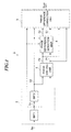
- Fig. 1 is a block diagram showing the structure of a phase correction circuit formed according to the present embodiment.
- the phase correction circuit 1 comprises a signal extraction section 2, a phase shifting unit 3, a phase difference detection unit 4, and a phase difference correction unit 5.
- the signal extraction section 2 includes a plurality of band pass filters BPF1 and BPF2 which pass therethrough only signal components of desired frequency contained in an input signal Sin.
- Both of the above-mentioned band pass filters BPF1 and BPF2 which are connected in series and each of which takes the above frequency f as a center frequency, are formed of band pass filters each having a pass band for passing a desired signal component contained in an input signal Sin and having various desired characteristics.
- the front band pass filter BPF1 passes a desired signal component S 1 having the frequency f and contained in the input signal Sin
- the rear band pass filter BPF2 further passes the signal component S 1 so that it is output as a signal component S2.
- phase shifting unit 3 shifts the phases of the signal components S 1 and S2 output from the band pass filters BPF 1 and BPF2 by ⁇ /2, thereby outputting signals P and P2 having their phases shifted (hereinafter referred to as "phase-shifted signals").
- the phase difference detection unit 4 receives the signal components S 1 and S2 from the band pass filters BPF1 and BPF2 as well as the phase-shifted signals P1 and P2 from the phase-shifting unit 3, performs a computation using an addition theorem of trigonometric function, thereby detecting a phase difference between the signal components S1 and S2, a phase difference between the signal component S2 and the phase-shifted signal P1, a phase difference between the signal component S1 and the phase-shifted signal P2, as well as a phase difference between the phase-shifted signals P1 and P2.
- phase difference detection unit 4 outputs signals E1 and E2 of orthogonal function whose parameters are detected phase differences ⁇ , i.e., phase difference detection signal E1 represented by sine wave Bsin( ⁇ ) and phase difference detection signal E2 represented by cosine wave Bcos( ⁇ ).
- the phase difference correction unit 5 shifts the phases of the phase-shifted signal P1 and the signal component S1 in accordance with the phase difference detection signals E1 and E2, thereby generating and producing an output signal Sout which is a signal component having its phase difference ⁇ corrected.
- the phase difference correction unit 5 performs a phase-shifting process expressed by the following matrix equation (4), and produces as an output signal Sout a signal component Ksin( ⁇ t) having the same phase as the signal component Asin( ⁇ t) contained in the input signal Sin.
- the phase difference correction unit 5 produces as an output signal Sout a signal component Kcos ( ⁇ t) having its phase shifted by ⁇ /2 with respect to the signal component Asin ( ⁇ t) contained in the input signal Sin.
- either one or both of the signal component Ksin ( ⁇ t) and the signal component Kcos ( ⁇ t) are output as an output signal Sout.
- the coefficient K represents an amplitude.
- the phase difference correction unit 5 performs a processing (which is a computation using an addition theorem of trigonometric function) represented by the following equations (5-a) and (5-b) obtained by developing the above matrix equation (4), thereby generating the signal components Kcos( ⁇ t) and Ksin( ⁇ t) having corrected the phase differences (phase deviations) of the band pass filters BPF1 and BPF2, thus outputting the same as the output signal Sout.
- a processing which is a computation using an addition theorem of trigonometric function represented by the following equations (5-a) and (5-b) obtained by developing the above matrix equation (4), thereby generating the signal components Kcos( ⁇ t) and Ksin( ⁇ t) having corrected the phase differences (phase deviations) of the band pass filters BPF1 and BPF2, thus outputting the same as the output signal Sout.
- the phase correction circuit 1 of the present embodiment operates in accordance with signal components S1 and S2 extracted from the input signal Sin by the band pass filters BPF1 and BPF2 having all the desired characteristics, as well as the phase-shifted signals P1 and P2 formed by shifting the phases of these signal components S1 and S2 by ⁇ /2.
- the phase difference detection unit 4 detects the phase differences (phase deviations) ⁇ of the signal components S1 and S2, while the phase difference correction unit 5 operates in accordance with the phase difference detection signals E1 and E2 which are orthogonal functions taking the detected phase differences as parameters, so as to shift the phases of the phase-shifted signal P1 and the signal component S1, thereby generating a signal component having its phase deviation corrected, and thus outputting the same as an output signal Sout.
- phase correction circuit 1 of the present embodiment since no feedback loop exists in a process which lasts until it extracts a desired signal component from an input signal Sin and outputs an output signal Sout, it is possible to extremely quickly generate an output signal Sout having its phase deviation corrected.
- an FM detection signal detected by the receiver is input as an input signal Sin and the center frequency f of the band pass filters BPF 1 and BPF2 is set at 19 kHz, it is possible to instantly extract a pilot signal having its phase deviation corrected if it appears to be necessary to extract a pilot signal contained in the FM detection signal. Further, when demodulation or the like is applied to the FM detection signal in synchronism with the extracted pilot signal so as to generate an audio signal which is then supplied to a speaker, it is possible to reproduce a sound which is free from any tremble.
- the phase correction circuit 1 of the present embodiment can also be formed of an analog circuit capable of performing an analog signal processing, or a digital circuit which performs a digital signal processing.
- the band pass filters BPF1 and BPF2 can be formed of digital filters which perform digital filtering in synchronism with a sampling clock having a higher frequency than the Nyquist frequency.
- the phase shifting unit 3, the phase difference detection unit 4, and phase difference correction unit 5 can be similarly formed of digital circuits which perform digital signal processing in synchronism with the sampling clock. In this way, the digital signal A/D converted using the sampling frequency of the above sampling clock is processed as an input signal Sin, rendering it possible to generate a desired signal component having its phase deviation corrected, as an output signal Sout consisting of digital signal.
- phase correction circuit 1 is formed of digital circuit, it is possible to correct a phase deviation with an acceptable precision, thereby generating and thus outputting an output signal Sout consisting of digital signal, without depending upon a frequency precision of a desired signal component and the precision of the sampling clock.
- phase shifting amount with respect to the signal components S 1 and S2 of the phase-shifting unit 3 is ⁇ /2, it is also possible to perform a phase shifting by - ⁇ /2.
- the phase difference correction unit 5 shifts the phases of the phase-shifted signal P1 and the signal component S1 in accordance with the phase difference detection signals E1 and E2, thereby generating an output signal Sout having phase deviation corrected.
- the phase difference correction unit 5 shifts the phases of the phase-shifted signal P2 and the signal component S2 each having a phase deviation equal to a phase difference 2 ⁇ , in accordance with the phase difference detection signals E12 and E22 which are the orthogonal functions taking phase differences 2 ⁇ as parameters, thereby generating an output signal Sout having phase deviation corrected.
- phase correction circuit 1 shown in Fig. 1 contains two band pass filters BPF1 and BPF2
- the phase correction circuit of the present embodiment has an extendibility.
- n (n is 2 or more) band pass filters BPF1 - BPFn having the same characteristic are connected in series, it is possible to correct a phase deviation occurred in any one band pass filter among the band pass filters BPF1 - BPFn, thereby generating an output signal Sout not involving any phase deviation.
- the phase difference detection unit 4 detects a phase difference detection signal E1m represented by Bcos(m ⁇ ) and another phase difference detection signal E2m represented by Bsin(m ⁇ ), which are orthogonal functions taking as parameters phase differences m ⁇ equivalent to an arbitrary number of stages m (m ⁇ n) output from the band pass filters BPF1 - BPFn.
- the phase difference correction unit 5 can, as shown in the following equation (7), shift the phases of the signal component Sm and the phase-shifted signal Pm having a phase deviation equal to a phase difference m ⁇ , in accordance with the phase difference detection signals E1m and E2m, thereby generating and thus outputting an output signal Sout having the phase difference m ⁇ corrected.
- phase correction circuit 1 can extract the desired signal components S1 and S2 by virtue of the band pass filters BPF1 and BPF2, it is also possible to replace the band pass filters BPF1 and BPF2 with other types of filters such as high pass filter and low pass filter, thereby correcting a phase deviation when extracting a desired signal component.
- phase correction circuit 1 of the present embodiment should not be limited to the use in correcting a phase deviation when extracting a desired pilot signal from an FM detection signal, but has a versatility which makes it possible for the phase correction circuit to be used in various fields.
- phase correction circuit 1 it is also possible to prepare a computer program which can provide the same functions as the above-described phase correction circuit 1 by virtue of electronic computation means such as a microprocessor (MPU) and a digital signal processor (DSP), thereby allowing the microprocessor (MPU) and the digital signal processor (DSP) or the like to operate in accordance with the computer program, thus effecting a desired phase correction.
- electronic computation means such as a microprocessor (MPU) and a digital signal processor (DSP)
- DSP digital signal processor
- Fig. 2(a) is a block diagram showing the structures of the signal extraction unit 2 and the phase-shifting unit 3
- Fig. 2(b) is a block diagram showing the structure of the phase difference detection unit 4
- Fig. 2(c) is a block diagram showing the structure of the phase difference correction unit 5.
- the signal extraction unit 2 is formed by including the band pass filters BPF 1 and BPF2 covering all desired characteristics, each having a predetermined pass band with a predetermined frequency f as its center frequency.
- the band pass filters will extract and then output the desired signal components as signal components S1 and S2 having phase differences ⁇ , 2 ⁇ .
- the phase-shifting unit 3 includes: a phase-shifter 3a which shifts the phase of the signal component S2 by ⁇ /2 and then outputs a phase-shifted signal P2; and a phase-shifter 3b which shifts the phase of the signal component S 1 by ⁇ /2 and then outputs a phase-shifted signal P1.
- the signal components S1 and S2 shown in the equations (1-b), (1-c) are output from the band pass filters BPF1 and BPF2, while the phase-shifted signals P1, P2 shown in the equations (2-a), (2-b) are output from the phase shifters 3a and 3b.
- the phase difference detection unit 4 is formed by including multipliers 4a, 4b, 4c, 4d, an adder 4e and a subtractor 4f.
- the multiplier 4a multiplies together signal components S 1 and S2
- the multiplier 4b multiplies together a signal component S2 and a phase-shifted signal P1
- the multiplier 4c multiplies together a signal component S 1 and a phase-shifted signal P2
- the multiplier 4d multiplies together the phase-shifted signals P1 and P2
- the adder 4e adds together the multiplication results of the multipliers 4a and 4d
- the subtractor 4f subtracts the computation result of the multiplier 4b from the computation result of the multiplier 4c.
- a phase difference detection signal E1 expressed by the sine wave Bsin( ⁇ ) which is an orthogonal function taking a phase difference ⁇ as its parameter will be output from the subtractor 4f, as shown in the following equation (8-a), while the adder 4e outputs a phase difference detection signal E2 represented by the cosine wave Bsin( ⁇ ) which is an orthogonal function taking a phase difference ⁇ as its parameter, as shown in the following equation (8-b).
- the phase difference correction unit 5 is formed by including multipliers 5a, 5b, 5c, 5d, a subtractor 5e, and an adder 5f.
- the multiplier 5a multiplies together a signal component S1 and a phase difference detection signal E1
- the multiplier 5b multiplies together a phase difference detection signal E1 and a phase-shifted signal P
- the multiplier 5c multiplies together a signal component S1 and a phase difference detection signal E2
- the multiplier 5d multiplies together a phase difference detection signal E2 and a phase-shifted signal P1.
- the subtractor 5e subtracts the computation result of the multiplier 5a from the computation result of the multiplier 5d, while the adder 5f adds together the multiplication results of the multipliers 5b and 5c.
- a phase shifting processing shown in the above equation (4) will be carried out, and the subtractor 5e will produce an output signal Sout represented by the cosine wave Kcos( ⁇ t) shown in the above equation (5-a) and having phase deviation corrected, while the adder 5f produces an output signal Sout represented by the sine wave Ksin ( ⁇ t) shown in the above equation (5-b) and having phase deviation corrected.
- phase correction circuit of the present embodiment since the phase difference detection unit 4 and the phase difference correction unit 5 are formed by including a number of multipliers, an adder, and a subtractor, it is possible for the phase correction circuit to reduce the number of its elements, so that the circuit becomes simple in its structure and compact in size. Further, it is also possible to provide a phase correction circuit capable of a high speed processing.
- phase correction circuit of the present embodiment can be formed either of an analog circuit which performs an analog signal processing, or a digital circuit which performs a digital signal processing.
- phase correction circuit When the phase correction circuit is formed of a digital circuit, it is possible to highly accurately correct a phase deviation, generate and thus output an output signal Sout consisting of digital signal, without depending upon a frequency precision of a desired signal and the precision of a sampling clock.
- Fig. 3(a) is a block diagram showing the structure of the phase difference detection unit 4 and Fig. 3(b) is a block diagram showing the structure of the phase difference correction unit 5.
- the phase correction circuit of the present embodiment includes a signal extraction unit 2 and a phase-shifting unit 3.
- Signal components S1, S2 and phase-shifted signals P1, P2 output from the signal extraction unit 2 and the phase-shifting unit 3 are supplied to the phase difference detection unit 4 shown in Fig. 3(a) .
- the phase difference detection signals E12, E22 and the signal component S2 generated by the phase difference detection unit 4, as well as the phase-shifted signal P2 are supplied to the phase difference correction unit 5, thereby allowing the phase difference correction unit 5 to output an output signal Sout having phase deviation corrected.
- the phase difference detection unit 4 comprises: a front side phase difference detector 4F having the same structure as the phase difference detection unit 4 shown in Fig. 2(b) ; and a rear side phase difference detector 4R which receives the phase difference detection signals E1, E2 output from the phase difference detector 4F and outputs the phase difference detection signals E12, E22 which have been given a further phase difference ⁇ .
- the rear side phase difference detector 4R includes multipliers 4g, 4h, 4i, an adder 4j and a subtractor 4k.
- the adder 4j adds the multiplication result, thereby generating a phase difference detection signal E12 having a phase difference 2 ⁇ .
- the subtractor 4k operates to calculate a difference between a computation result obtained by squaring the phase difference detection signal E2 using the multiplier 4i and a computation result obtained by squaring the phase difference detection signal E1 using the multiplier 4h, thereby generating a phase difference detection signal E22 having a phase difference 2 ⁇ .
- the phase difference correction unit 5 has the same structure as the phase difference correction unit 5 shown in Fig. 2(c) . Nevertheless, the phase difference correction unit 5 of the present embodiment receives the phase difference detection signals E12 and E22 each having a phase difference 2 ⁇ , a signal component S2 and a phase-shifted signal P2 each having a phase difference 2 ⁇ .
- the subtractor 5e outputs an output signal Sout represented by a cosine wave Kcos( ⁇ t) having phase difference 2 ⁇ corrected, as shown in the following equation (9-a), while the adder 5f outputs an output signal Sout represented by a sine wave Ksin( ⁇ t) having its phase difference 2 ⁇ corrected, as shown in the following equation (9-b).
- the phase difference correction unit 5 operates in accordance with the phase difference detection signals E12 and E22 which are orthogonal functions taking a phase difference 2 ⁇ as a parameter, so as to shift the phases of the signal component S2 and the phase-shifted signal P2 each having a phase difference 2 ⁇ , thereby making it possible to produce an output signal Sout having phase deviation corrected.
- phase correction circuit of the present embodiment can be formed either of an analog circuit which performs an analog signal processing, or a digital circuit which performs a digital signal processing.
- phase correction circuit When the phase correction circuit is formed of a digital circuit, it is possible to highly accurately correct a phase deviation, generate and thus output an output signal Sout consisting of digital signal, without depending upon a frequency precision of a desired signal and the precision of a sampling clock.
- the phase shifting unit 3 operates to shift by ⁇ /2 the phases of the respective signal components S1 and S2 output from the band pass filters BPF1 and BPF2 connected in series, thereby generating the phase-shifted signals P1 and P2.
- the phase correction circuit of the present embodiment as shown in Fig. 4 , there are provided two filter groups G1 and G2 consisting of the band pass filters BPF1 and BPF2 having various desired characteristics.
- One filter group G1 is provided on its input side with a phase shifting unit 3 capable of shifting a phase by ⁇ /2 , while the other filter group G2 is not provided with any phase shifting unit.
- the respective signal components S 1 and S2 output from the filter group G2 and the phase-shifted signals P1 and P2 output from the filter group G1 are supplied to the phase difference detection unit 4, thereby generating the phase difference detection signals E1 and E2. Further, the phase difference detection signals E1 and E2, the signal component S1 and the phase-shifted signal P are supplied to the phase difference correction unit 5, thereby generating and thus outputting an output signal Sout having phase difference ⁇ corrected.
- phase correction circuit of the present embodiment it is possible to at first shift the phase of an input signal Sin by virtue of the phase-shifting unit 3, and then allow the input signal to pass through the band pass filters BFP and BP2.
- phase correction circuit of the present embodiment can be formed either of an analog circuit which performs an analog signal processing, or a digital circuit which performs a digital signal processing.
- phase correction circuit When the phase correction circuit is formed of a digital circuit, it is possible to highly accurately correct a phase deviation, generate and thus output an output signal Sout consisting of digital signal, without depending upon a frequency precision of a desired signal and the precision of a sampling clock.
Abstract
Description
- The present invention relates to a phase correction circuit which carries out an extraction or the like of desired signal components without causing phase deviations during a signal processing.
- As a technique for extracting desired signal components during a signal processing, there has been known, for example, a pilot signal extraction circuit which extracts, from an FM detection signal detected by a detector of an FM receiver, a pilot signal for use in a signal processing such as demodulation or the like.
- Conventionally, in the above-mentioned pilot signal extraction circuit, it is usual to frequency separate and thus extract a pilot signal having a frequency of 19 kHz from an FM detection signal by means of a high-Q (Q factor) band pass filter, and to use PLL circuit to correct a phase deviation of the pilot signal occurred when passing through the band pass filter, thereby extracting a pilot signal not involving any phase deviation. Further, a pilot-signal involving a phase deviation occurred when passing through the above high-Q band pass filter is sampled in synchronism with a sampling clock which is integer times of 19 kHz, followed by applying a digital signal processing to the sampled digital signal, thereby generating a pilot signal not containing any phase deviation.
- However, in the above-mentioned conventional pilot signal extraction circuit which extracts a pilot-signal by virtue of the band pass filter and PLL circuit, since there is a delay during a process in which the PLL circuit applies a phase-lock to the pilot signal, it is impossible to effect a maximum separation. Besides, if an audio signal demodulated by a pilot signal not synchronized is reproduced by a speaker, there will be a problem such as a sound tremble.
- Moreover, in the above-mentioned conventional pilot signal extraction circuit which, by virtue of digital signal processing, corrects a phase deviation of a pilot signal extracted by the band pass filter, since the operation of the extraction circuit depends on a frequency precision of a pilot signal contained in an FM wave as well as depends on the precision of the sampling clock, the problem of phase deviation will become even more severe.
- The present invention has been accomplished in view of the above conventional problem and it is an object of the invention to provide a phase correction circuit which can perform a high speed processing, correct a phase deviation with a high precision, and thus extract desired signal components.
- Moreover, it is another object of the present invention to provide a phase correction circuit which cannot only extract a pilot signal from an FM detection signal, but also has a versatility capable of use in various technical fields.
- The invention recited in
claim 1 provides a phase correction circuit for correcting a phase difference of a desired signal component contained in an input signal and then extracting the desired signal component, the phase correction circuit comprising: filter means having characteristics of several stages for extracting the desired signal component contained in the input signal; phase shifting means for shifting a predetermined amount of phase of a signal component extracted by each filter means and generating a phase-shifted signal; phase difference detection means for performing a computation using an addition theorem of trigonometric functions to process the signal component extracted by each filter means and the phase-shifted signal generated by the phase shifting means, thereby detecting a phase difference of the signal component; and phase difference correction means for shifting the phase of the signal component extracted by each filter means and the phase of the phase-shifted signal in accordance with the phase difference detected by the phase difference detection means, thereby generating a signal component having the phase difference corrected. - The invention recited in
claim 2 provides a phase correction circuit for correcting a phase difference of a desired signal component contained in an input signal and then extracting the desired signal component, the phase correction circuit comprising: first filter means having characteristics of several stages for extracting a desired signal component contained in the input signal; phase shifting means for shifting a predetermined amount of phase of the input signal; second filter means having characteristics consistent with the first filter means for extracting, from an output signal of the phase shifting means, a phase-shifted signal formed by shifting the predetermined amount of phase of the desired signal component contained in the input signal; phase difference detection means for performing a computation using an addition theorem of trigonometric functions to process the signal component extracted by the first filter means and the phase-shifted signal extracted by the second filter means, thereby detecting a phase difference of the signal component; and phase difference correction means for shifting the phase of the signal component extracted by the first filter means and the phase-shifted signal extracted by the second filter means in accordance with the phase difference detected by the phase difference detection means, thereby generating a signal component having the phase difference corrected. -
- Fig. 1
- is a block diagram showing the structure of a phase correction circuit formed according to a preferred embodiment.
- Fig. 2
- is a block diagram showing the structure of a phase correction circuit formed according to one embodiment.
- Fig. 3
- is a block diagram showing the structure of a phase correction circuit formed according to another embodiment.
- Fig. 4
- is a block diagram showing the structure of a phase correction circuit formed according to a further embodiment.
- A preferred embodiment of the present invention will be described with reference to
Fig. 1 which is a block diagram showing the structure of a phase correction circuit formed according to the present embodiment. - As shown in
Fig. 1 , thephase correction circuit 1 comprises asignal extraction section 2, aphase shifting unit 3, a phasedifference detection unit 4, and a phasedifference correction unit 5. Thesignal extraction section 2 includes a plurality of band pass filters BPF1 and BPF2 which pass therethrough only signal components of desired frequency contained in an input signal Sin. - Both of the above-mentioned band pass filters BPF1 and BPF2 which are connected in series and each of which takes the above frequency f as a center frequency, are formed of band pass filters each having a pass band for passing a desired signal component contained in an input signal Sin and having various desired characteristics. In more detail, the front band pass filter BPF1 passes a desired
signal component S 1 having the frequency f and contained in the input signal Sin, while the rear band pass filter BPF2 further passes thesignal component S 1 so that it is output as a signal component S2. - Therefore, as shown in the following equation (1-a), if sine wave Asin (ωt) represents a desired signal component contained in an input signal Sin, f(t) represents other signal components, and α represents various phase differences (phase deviations) of signal components having passed through the band
pass filters BPF 1 and BPF2, asignal component S 1 output from the bandpass filter BPF 1 will deviate a phase α, as shown in the following equation (1-b), while a signal component S2 output from the band pass filter BPF2 will deviate a phase 2α, as shown in the following equation (1-c). -

- The
phase shifting unit 3 shifts the phases of thesignal components S 1 and S2 output from the bandpass filters BPF 1 and BPF2 by π/2, thereby outputting signals P and P2 having their phases shifted (hereinafter referred to as "phase-shifted signals"). - Therefore, the signal components S1 and S2 will become phase-shifted signals P1 and P2 represented by the following equations (2-a), (2-b) and thus output.
-

- The phase
difference detection unit 4 receives thesignal components S 1 and S2 from the band pass filters BPF1 and BPF2 as well as the phase-shifted signals P1 and P2 from the phase-shifting unit 3, performs a computation using an addition theorem of trigonometric function, thereby detecting a phase difference between the signal components S1 and S2, a phase difference between the signal component S2 and the phase-shifted signal P1, a phase difference between the signal component S1 and the phase-shifted signal P2, as well as a phase difference between the phase-shifted signals P1 and P2.
Then, as shown in the following equations (3-a) and (3-b), the phasedifference detection unit 4 outputs signals E1 and E2 of orthogonal function whose parameters are detected phase differences α, i.e., phase difference detection signal E1 represented by sine wave Bsin(α) and phase difference detection signal E2 represented by cosine wave Bcos(α). -

- The phase
difference correction unit 5 shifts the phases of the phase-shifted signal P1 and the signal component S1 in accordance with the phase difference detection signals E1 and E2, thereby generating and producing an output signal Sout which is a signal component having its phase difference α corrected. - Namely, the phase
difference correction unit 5 performs a phase-shifting process expressed by the following matrix equation (4), and produces as an output signal Sout a signal component Ksin(ωt) having the same phase as the signal component Asin(ωt) contained in the input signal Sin. Alternatively, the phasedifference correction unit 5 produces as an output signal Sout a signal component Kcos (ωt) having its phase shifted by π/2 with respect to the signal component Asin (ωt) contained in the input signal Sin.
Then, in response to an operating state of thephase correction circuit 1 of the present embodiment, either one or both of the signal component Ksin (ωt) and the signal component Kcos (ωt) are output as an output signal Sout. Here, the coefficient K represents an amplitude. -

- As explained in more detail, the phase
difference correction unit 5 performs a processing (which is a computation using an addition theorem of trigonometric function) represented by the following equations (5-a) and (5-b) obtained by developing the above matrix equation (4), thereby generating the signal components Kcos(ωt) and Ksin(ωt) having corrected the phase differences (phase deviations) of the band pass filters BPF1 and BPF2, thus outputting the same as the output signal Sout. -

- As explained above, the
phase correction circuit 1 of the present embodiment operates in accordance with signal components S1 and S2 extracted from the input signal Sin by the band pass filters BPF1 and BPF2 having all the desired characteristics, as well as the phase-shifted signals P1 and P2 formed by shifting the phases of these signal components S1 and S2 by π/2.
The phasedifference detection unit 4 detects the phase differences (phase deviations) α of the signal components S1 and S2, while the phasedifference correction unit 5 operates in accordance with the phase difference detection signals E1 and E2 which are orthogonal functions taking the detected phase differences as parameters, so as to shift the phases of the phase-shifted signal P1 and the signal component S1, thereby generating a signal component having its phase deviation corrected, and thus outputting the same as an output signal Sout. - In this way, according to the
phase correction circuit 1 of the present embodiment, since no feedback loop exists in a process which lasts until it extracts a desired signal component from an input signal Sin and outputs an output signal Sout, it is possible to extremely quickly generate an output signal Sout having its phase deviation corrected. - For this reason, as a concrete example, if an FM detection signal detected by the receiver is input as an input signal Sin and the center frequency f of the band
pass filters BPF 1 and BPF2 is set at 19 kHz, it is possible to instantly extract a pilot signal having its phase deviation corrected if it appears to be necessary to extract a pilot signal contained in the FM detection signal. Further, when demodulation or the like is applied to the FM detection signal in synchronism with the extracted pilot signal so as to generate an audio signal which is then supplied to a speaker, it is possible to reproduce a sound which is free from any tremble. - Moreover, the
phase correction circuit 1 of the present embodiment can also be formed of an analog circuit capable of performing an analog signal processing, or a digital circuit which performs a digital signal processing. For example, the band pass filters BPF1 and BPF2 can be formed of digital filters which perform digital filtering in synchronism with a sampling clock having a higher frequency than the Nyquist frequency.
Thephase shifting unit 3, the phasedifference detection unit 4, and phasedifference correction unit 5 can be similarly formed of digital circuits which perform digital signal processing in synchronism with the sampling clock. In this way, the digital signal A/D converted using the sampling frequency of the above sampling clock is processed as an input signal Sin, rendering it possible to generate a desired signal component having its phase deviation corrected, as an output signal Sout consisting of digital signal. - Then, when the
phase correction circuit 1 is formed of digital circuit, it is possible to correct a phase deviation with an acceptable precision, thereby generating and thus outputting an output signal Sout consisting of digital signal, without depending upon a frequency precision of a desired signal component and the precision of the sampling clock. - Moreover, although the above description shows that a phase shifting amount with respect to the
signal components S 1 and S2 of the phase-shiftingunit 3 is π/2, it is also possible to perform a phase shifting by -π/2. - Further, according to the above description, as shown in equations (4), (5-a), and (5-b), the phase
difference correction unit 5 shifts the phases of the phase-shifted signal P1 and the signal component S1 in accordance with the phase difference detection signals E1 and E2, thereby generating an output signal Sout having phase deviation corrected.
However, as shown in the following equation (6), it is also possible to shift the phases of the phase-shifted signal P2 and the signal component S2 each having a phase deviation equal to a phase difference 2α, in accordance with the phase difference detection signals E12 and E22 which are the orthogonal functions taking phase differences 2α as parameters, thereby generating an output signal Sout having phase deviation corrected. -

- Moreover, although the
phase correction circuit 1 shown inFig. 1 contains two band pass filters BPF1 and BPF2, the phase correction circuit of the present embodiment has an extendibility. In particular, when n (n is 2 or more) band pass filters BPF1 - BPFn having the same characteristic are connected in series, it is possible to correct a phase deviation occurred in any one band pass filter among the band pass filters BPF1 - BPFn, thereby generating an output signal Sout not involving any phase deviation. - Namely, the phase
difference detection unit 4 detects a phase difference detection signal E1m represented by Bcos(mα) and another phase difference detection signal E2m represented by Bsin(mα), which are orthogonal functions taking as parameters phase differences mα equivalent to an arbitrary number of stages m (m ≤ n) output from the band pass filters BPF1 - BPFn.
The phasedifference correction unit 5 can, as shown in the following equation (7), shift the phases of the signal component Sm and the phase-shifted signal Pm having a phase deviation equal to a phase difference mα, in accordance with the phase difference detection signals E1m and E2m, thereby generating and thus outputting an output signal Sout having the phase difference mα corrected. -

- Further, although the
phase correction circuit 1 described above can extract the desired signal components S1 and S2 by virtue of the band pass filters BPF1 and BPF2, it is also possible to replace the band pass filters BPF1 and BPF2 with other types of filters such as high pass filter and low pass filter, thereby correcting a phase deviation when extracting a desired signal component. - Moreover, the
phase correction circuit 1 of the present embodiment should not be limited to the use in correcting a phase deviation when extracting a desired pilot signal from an FM detection signal, but has a versatility which makes it possible for the phase correction circuit to be used in various fields. - Besides, it is also possible to prepare a computer program which can provide the same functions as the above-described
phase correction circuit 1 by virtue of electronic computation means such as a microprocessor (MPU) and a digital signal processor (DSP), thereby allowing the microprocessor (MPU) and the digital signal processor (DSP) or the like to operate in accordance with the computer program, thus effecting a desired phase correction. - Next, description will be given to explain a more concrete embodiment of the phase correction circuit of
Fig. 1 , with reference toFig. 2. Fig. 2(a) is a block diagram showing the structures of thesignal extraction unit 2 and the phase-shiftingunit 3,Fig. 2(b) is a block diagram showing the structure of the phasedifference detection unit 4,Fig. 2(c) is a block diagram showing the structure of the phasedifference correction unit 5. - As shown in
Fig. 2(a) , thesignal extraction unit 2 is formed by including the band pass filtersBPF 1 and BPF2 covering all desired characteristics, each having a predetermined pass band with a predetermined frequency f as its center frequency.
By allowing the desired signal components contained in an input signal Sin to pass through pass bands, the band pass filters will extract and then output the desired signal components as signal components S1 and S2 having phase differences α, 2α.
The phase-shiftingunit 3 includes: a phase-shifter 3a which shifts the phase of the signal component S2 by π/2 and then outputs a phase-shifted signal P2; and a phase-shifter 3b which shifts the phase of thesignal component S 1 by π/2 and then outputs a phase-shifted signal P1. By carrying out the computation using the above constitution, the signal components S1 and S2 shown in the equations (1-b), (1-c) are output from the band pass filters BPF1 and BPF2, while the phase-shifted signals P1, P2 shown in the equations (2-a), (2-b) are output from thephase shifters - Next, as shown in
Fig. 2(b) , the phasedifference detection unit 4 is formed by includingmultipliers adder 4e and asubtractor 4f. In more detail, themultiplier 4a multiplies togethersignal components S 1 and S2, themultiplier 4b multiplies together a signal component S2 and a phase-shifted signal P1, themultiplier 4c multiplies together asignal component S 1 and a phase-shifted signal P2, themultiplier 4d multiplies together the phase-shifted signals P1 and P2, theadder 4e adds together the multiplication results of themultipliers subtractor 4f subtracts the computation result of themultiplier 4b from the computation result of themultiplier 4c.
Upon performing the computations using the above constitution, a phase difference detection signal E1 expressed by the sine wave Bsin(α) which is an orthogonal function taking a phase difference α as its parameter will be output from the subtractor 4f, as shown in the following equation (8-a), while theadder 4e outputs a phase difference detection signal E2 represented by the cosine wave Bsin(α) which is an orthogonal function taking a phase difference α as its parameter, as shown in the following equation (8-b). -

- Next, as shown in
Fig. 2(c) , the phasedifference correction unit 5 is formed by includingmultipliers subtractor 5e, and anadder 5f. In more detail, themultiplier 5a multiplies together a signal component S1 and a phase difference detection signal E1, themultiplier 5b multiplies together a phase difference detection signal E1 and a phase-shifted signal P1, themultiplier 5c multiplies together a signal component S1 and a phase difference detection signal E2, themultiplier 5d multiplies together a phase difference detection signal E2 and a phase-shifted signal P1.
Further, thesubtractor 5e subtracts the computation result of themultiplier 5a from the computation result of themultiplier 5d, while theadder 5f adds together the multiplication results of themultipliers subtractor 5e will produce an output signal Sout represented by the cosine wave Kcos(ωt) shown in the above equation (5-a) and having phase deviation corrected, while theadder 5f produces an output signal Sout represented by the sine wave Ksin (ωt) shown in the above equation (5-b) and having phase deviation corrected. - In this way, according to the phase correction circuit of the present embodiment, since the phase
difference detection unit 4 and the phasedifference correction unit 5 are formed by including a number of multipliers, an adder, and a subtractor, it is possible for the phase correction circuit to reduce the number of its elements, so that the circuit becomes simple in its structure and compact in size. Further, it is also possible to provide a phase correction circuit capable of a high speed processing. - Moreover, since no feedback loop exists in a process which lasts until it extracts a desired signal component from an input signal Sin and outputs an output signal Sout having phase deviation corrected, it is possible to extremely quickly generate an output signal Sout having phase deviation corrected.
- Further, the phase correction circuit of the present embodiment can be formed either of an analog circuit which performs an analog signal processing, or a digital circuit which performs a digital signal processing.
- When the phase correction circuit is formed of a digital circuit, it is possible to highly accurately correct a phase deviation, generate and thus output an output signal Sout consisting of digital signal, without depending upon a frequency precision of a desired signal and the precision of a sampling clock.
- Next, description will be given to explain other embodiment equivalent to a modification of the phase correction circuit shown in
Fig. 2 , with reference toFig. 3 .
Fig. 3(a) is a block diagram showing the structure of the phasedifference detection unit 4 andFig. 3(b) is a block diagram showing the structure of the phasedifference correction unit 5. - The phase correction circuit of the present embodiment includes a
signal extraction unit 2 and a phase-shiftingunit 3. Signal components S1, S2 and phase-shifted signals P1, P2 output from thesignal extraction unit 2 and the phase-shiftingunit 3 are supplied to the phasedifference detection unit 4 shown inFig. 3(a) .
Further, the phase difference detection signals E12, E22 and the signal component S2 generated by the phasedifference detection unit 4, as well as the phase-shifted signal P2 are supplied to the phasedifference correction unit 5, thereby allowing the phasedifference correction unit 5 to output an output signal Sout having phase deviation corrected. - Namely, as shown in
Fig. 3(a) , the phasedifference detection unit 4 comprises: a front sidephase difference detector 4F having the same structure as the phasedifference detection unit 4 shown inFig. 2(b) ; and a rear sidephase difference detector 4R which receives the phase difference detection signals E1, E2 output from thephase difference detector 4F and outputs the phase difference detection signals E12, E22 which have been given a further phase difference α. - Here, the rear side
phase difference detector 4R includesmultipliers adder 4j and a subtractor 4k. After themultiplier 4g has multiplied together the phase difference detection signals E1 and E2 output from thephase difference detector 4F, theadder 4j adds the multiplication result, thereby generating a phase difference detection signal E12 having a phase difference 2α.
Further, thesubtractor 4k operates to calculate a difference between a computation result obtained by squaring the phase difference detection signal E2 using themultiplier 4i and a computation result obtained by squaring the phase difference detection signal E1 using themultiplier 4h, thereby generating a phase difference detection signal E22 having a phase difference 2α. - Next, as shown in
Fig. 3(b) , the phasedifference correction unit 5 has the same structure as the phasedifference correction unit 5 shown inFig. 2(c) . Nevertheless, the phasedifference correction unit 5 of the present embodiment receives the phase difference detection signals E12 and E22 each having a phase difference 2α, a signal component S2 and a phase-shifted signal P2 each having a phase difference 2α.
By virtue of the above constitution, the subtractor 5e outputs an output signal Sout represented by a cosine wave Kcos(ωt) having phase difference 2α corrected, as shown in the following equation (9-a), while theadder 5f outputs an output signal Sout represented by a sine wave Ksin(ωt) having its phase difference 2α corrected, as shown in the following equation (9-b). -

- As described above, according to the phase correction circuit of the present embodiment, the phase
difference correction unit 5 operates in accordance with the phase difference detection signals E12 and E22 which are orthogonal functions taking a phase difference 2α as a parameter, so as to shift the phases of the signal component S2 and the phase-shifted signal P2 each having a phase difference 2α, thereby making it possible to produce an output signal Sout having phase deviation corrected. - Moreover, since no feedback loop exists in a process which lasts until it extracts a desired signal component from an input signal Sin and outputs an output signal Sout having phase deviation corrected, it is possible to extremely quickly generate an output signal Sout having phase deviation corrected.
- Further, the phase correction circuit of the present embodiment can be formed either of an analog circuit which performs an analog signal processing, or a digital circuit which performs a digital signal processing.
- When the phase correction circuit is formed of a digital circuit, it is possible to highly accurately correct a phase deviation, generate and thus output an output signal Sout consisting of digital signal, without depending upon a frequency precision of a desired signal and the precision of a sampling clock.
- Next, description will be given to explain a further embodiment corresponding to a modification of the embodiment shown in
Fig. 2 , with reference toFig. 4 . - In the embodiment shown in
Fig. 2 , as shown inFig. 2(a) , thephase shifting unit 3 operates to shift by π/2 the phases of the respective signal components S1 and S2 output from the band pass filters BPF1 and BPF2 connected in series, thereby generating the phase-shifted signals P1 and P2. However, in the phase correction circuit of the present embodiment, as shown inFig. 4 , there are provided two filter groups G1 and G2 consisting of the band pass filters BPF1 and BPF2 having various desired characteristics.
One filter group G1 is provided on its input side with aphase shifting unit 3 capable of shifting a phase by π/2, while the other filter group G2 is not provided with any phase shifting unit. By virtue of the above constitution, the respectivesignal components S 1 and S2 output from the filter group G2 and the phase-shifted signals P1 and P2 output from the filter group G1 are supplied to the phasedifference detection unit 4, thereby generating the phase difference detection signals E1 and E2.
Further, the phase difference detection signals E1 and E2, the signal component S1 and the phase-shifted signal P are supplied to the phasedifference correction unit 5, thereby generating and thus outputting an output signal Sout having phase difference α corrected. - Thus, according to the phase correction circuit of the present embodiment, it is possible to at first shift the phase of an input signal Sin by virtue of the phase-shifting
unit 3, and then allow the input signal to pass through the band pass filters BFP and BP2. - Moreover, since no feedback loop exists in a process which lasts until it extracts a desired signal component from an input signal Sin and outputs an output signal Sout having phase deviation corrected, it is possible to extremely quickly generate an output signal Sout having phase deviation corrected.
- Further, the phase correction circuit of the present embodiment can be formed either of an analog circuit which performs an analog signal processing, or a digital circuit which performs a digital signal processing.
- When the phase correction circuit is formed of a digital circuit, it is possible to highly accurately correct a phase deviation, generate and thus output an output signal Sout consisting of digital signal, without depending upon a frequency precision of a desired signal and the precision of a sampling clock.
Claims (6)
- A phase correction circuit for correcting a phase difference of desired signal component contained in an input signal and then extracting desired signal component, the phase correction circuit comprising:filter means having characteristics of several stages for extracting desired signal component contained in the input signal;phase shifting means for shifting a predetermined amount of phase of a signal component extracted by each filter means and generating a phase-shifted signal;phase difference detection means for performing a computation using an addition theorem of trigonometric functions to process the signal component extracted by each filter means and the phase-shifted signal generated by the phase shifting means, thereby detecting a phase difference of the signal component; andphase difference correction means for shifting the phase of the signal component extracted by each filter means and the phase of the phase-shifted signal in accordance with the phase difference detected by the phase difference detection means, thereby generating a signal component having the phase difference corrected.
- A phase correction circuit for correcting a phase difference of desired signal component contained in an input signal and then extracting desired signal component, the phase correction circuit comprising:filter means having characteristics of several stages for extracting desired signal component contained in the input signal;phase shifting means for shifting a predetermined amount of phase of the input signal;second filter means having characteristics consistent with the first filter means for extracting, from an output signal of the phase shifting means, a phase-shifted signal formed by shifting the predetermined amount of phase of a desired signal component contained in the input signal;phase difference detection means for performing a computation using an addition theorem of trigonometric functions to process the signal component extracted from the first filter means and the phase-shifted signal extracted from the second filter means, thereby detecting a phase difference of the signal component; andphase difference correction means for shifting the phase of the signal component extracted from the first filter means and the phase-shifted signal extracted from the second filter means in accordance with the phase difference detected by the phase difference detection means, thereby generating a signal component having the phase difference corrected.
- The phase correction circuit according to claim 1 or 2, wherein the shifted amount of phase is π/2 or -π/2.
- The phase correction circuit according to any one of claims 1 to 3,
wherein the phase difference detection means generates signal of orthogonal function taking detected phase difference as parameter;
wherein the phase difference correction means shifts the phases of the signal component and the phase-shifted signal in accordance with the signal of the orthogonal function, thereby generating a signal component having the phase difference corrected. - A phase correction method for correcting a phase difference of desired signal component contained in an input signal and then extracting desired signal component, the phase correction method comprising:an extraction step for extracting desired signal component contained in the input signal by virtue of filter means having characteristics of several stages;a phase shifting step for shifting a predetermined amount of phase of signal component extracted in the extraction step and generating phase-shifted signal;a phase difference detection step for performing a computation using an addition theorem of trigonometric functions to process signal component extracted in the extraction step and phase-shifted signal generated in the phase shifting step, thereby detecting a phase difference of signal component; andphase difference correction step for shifting the phase of signal component and the phase of phase-shifted signal in accordance with the phase difference detected in the phase difference detection step, thereby generating a signal component having the phase difference corrected.
- A phase correction method for correcting a phase difference of desired signal component contained in an input signal and then extracting desired signal component, the phase correction method comprising:a signal component extraction step for extracting desired signal component contained in the input signal by virtue of the first filter means having characteristics of several stages;a phase shifting step for shifting a predetermined amount of phase of the input signal;a phase signal extraction step for extracting, from a signal phase-shifted in the phase shifting step, a phase-shifted signal formed by shifting a predetermined amount of phase of desired signal component contained in the input signal, by virtue of second filter means having characteristics consistent with the first filter means;a phase difference detection step for performing a computation using an addition theorem of trigonometric functions to process signal component extracted in the signal component extraction step and phase-shifted signal extracted in the phase signal extraction step, thereby detecting a phase difference of the signal component; anda phase difference correction step for shifting the phase of signal component and the phase of phase-shifted signal in accordance with the phase difference detected in the phase difference detection step, thereby generating a signal component having the phase difference corrected.
Applications Claiming Priority (2)
| Application Number | Priority Date | Filing Date | Title |
|---|---|---|---|
| JP2005180429 | 2005-06-21 | ||
| PCT/JP2006/310338 WO2006137238A1 (en) | 2005-06-21 | 2006-05-24 | Phase correcting circuit |
Publications (2)
| Publication Number | Publication Date |
|---|---|
| EP1895662A1 true EP1895662A1 (en) | 2008-03-05 |
| EP1895662A4 EP1895662A4 (en) | 2010-08-04 |
Family
ID=37570273
Family Applications (1)
| Application Number | Title | Priority Date | Filing Date |
|---|---|---|---|
| EP06756544A Withdrawn EP1895662A4 (en) | 2005-06-21 | 2006-05-24 | Phase correcting circuit |
Country Status (3)
| Country | Link |
|---|---|
| EP (1) | EP1895662A4 (en) |
| JP (1) | JP4588760B2 (en) |
| WO (1) | WO2006137238A1 (en) |
Cited By (2)
| Publication number | Priority date | Publication date | Assignee | Title |
|---|---|---|---|---|
| EP2482486A3 (en) * | 2011-01-31 | 2017-05-31 | Fujitsu Limited | Sampling clock synchronizing apparatus, digital coherent receiving apparatus, and sampling clock synchronizing method |
| US9722591B2 (en) | 2014-09-05 | 2017-08-01 | Fujitsu Limited | Phase adjustment device, phase difference detecting device and phase-adjusting method |
Citations (3)
| Publication number | Priority date | Publication date | Assignee | Title |
|---|---|---|---|---|
| US5341107A (en) * | 1992-06-12 | 1994-08-23 | U.S. Philips Corporation | FM quadrature demodulator with two phase comparison circuits |
| US20020196878A1 (en) * | 2001-05-10 | 2002-12-26 | Burkhard Dick | Anti-demodulator circuit, filtering device and demodulator circuit |
| US6714776B1 (en) * | 1999-09-28 | 2004-03-30 | Microtune (Texas), L.P. | System and method for an image rejecting single conversion tuner with phase error correction |
Family Cites Families (6)
| Publication number | Priority date | Publication date | Assignee | Title |
|---|---|---|---|---|
| JPH03128465A (en) * | 1989-07-24 | 1991-05-31 | Sony Corp | Frequency detecting circuit |
| JPH08265382A (en) * | 1995-03-28 | 1996-10-11 | Toshiba Corp | Phase correction modulating system and phase correction modulator |
| JP3281527B2 (en) * | 1996-01-17 | 2002-05-13 | 松下電器産業株式会社 | Frequency offset compensator |
| JPH10126359A (en) * | 1996-10-18 | 1998-05-15 | Matsushita Electric Ind Co Ltd | Stereo receiver |
| JP4072652B2 (en) * | 1998-03-06 | 2008-04-09 | ソニー株式会社 | Phase shifter, voltage controlled oscillation circuit, demodulation circuit, and signal processing device |
| JP4405622B2 (en) * | 1999-08-27 | 2010-01-27 | アイホン株式会社 | FM demodulation circuit |
-
2006
- 2006-05-24 EP EP06756544A patent/EP1895662A4/en not_active Withdrawn
- 2006-05-24 WO PCT/JP2006/310338 patent/WO2006137238A1/en active Application Filing
- 2006-05-24 JP JP2007522219A patent/JP4588760B2/en not_active Expired - Fee Related
Patent Citations (3)
| Publication number | Priority date | Publication date | Assignee | Title |
|---|---|---|---|---|
| US5341107A (en) * | 1992-06-12 | 1994-08-23 | U.S. Philips Corporation | FM quadrature demodulator with two phase comparison circuits |
| US6714776B1 (en) * | 1999-09-28 | 2004-03-30 | Microtune (Texas), L.P. | System and method for an image rejecting single conversion tuner with phase error correction |
| US20020196878A1 (en) * | 2001-05-10 | 2002-12-26 | Burkhard Dick | Anti-demodulator circuit, filtering device and demodulator circuit |
Non-Patent Citations (1)
| Title |
|---|
| See also references of WO2006137238A1 * |
Cited By (3)
| Publication number | Priority date | Publication date | Assignee | Title |
|---|---|---|---|---|
| EP2482486A3 (en) * | 2011-01-31 | 2017-05-31 | Fujitsu Limited | Sampling clock synchronizing apparatus, digital coherent receiving apparatus, and sampling clock synchronizing method |
| US9722591B2 (en) | 2014-09-05 | 2017-08-01 | Fujitsu Limited | Phase adjustment device, phase difference detecting device and phase-adjusting method |
| US9859881B2 (en) | 2014-09-05 | 2018-01-02 | Fujitsu Limited | Phase difference detecting device |
Also Published As
| Publication number | Publication date |
|---|---|
| WO2006137238A1 (en) | 2006-12-28 |
| EP1895662A4 (en) | 2010-08-04 |
| JPWO2006137238A1 (en) | 2009-01-08 |
| JP4588760B2 (en) | 2010-12-01 |
Similar Documents
| Publication | Publication Date | Title |
|---|---|---|
| CN103051287B (en) | Any multiband for bandwidth multiplication covers frequency mixer device and method | |
| EP0540195A2 (en) | Digital quadrature radio receiver with two-step processing | |
| JP2004104779A (en) | Processing method and apparatus for modulating carrier having amplitude and phase error compensation | |
| US4636836A (en) | Phase locked loop system for providing a phase shifted output signal | |
| EP1895662A1 (en) | Phase correcting circuit | |
| EP2787410A2 (en) | Spurious frequency attenuation servo | |
| JP3845573B2 (en) | Phase detector and frequency stability measuring apparatus using the same | |
| EP1607721B1 (en) | Signal processing apparatus and method of differential transformer | |
| JPS61273005A (en) | Amplitude modulation system receiver | |
| CA2371148A1 (en) | Carrier tracking method | |
| JP3717856B2 (en) | Frequency measuring device | |
| JP5847762B2 (en) | Method and apparatus for demodulating an amplitude modulated signal | |
| CN101277102B (en) | Digital filter | |
| JP2552470B2 (en) | Detection circuit | |
| KR20000068083A (en) | Receiver for independent sideband signals | |
| RU2210088C2 (en) | Method of single-channel radio direction finding of quasiharmonic signals with minimal number of immobile omnidirectional antenna elements and facility for its realization | |
| US7336731B2 (en) | Demodulator with phase-adjusting function | |
| JP3923354B2 (en) | Automatic tracking antenna device | |
| JPS6324675Y2 (en) | ||
| WO2002056585A1 (en) | Receiver | |
| JPS59196655A (en) | Delay detecting circuit | |
| JP3072994B2 (en) | Control circuit with tracking filter | |
| JP3253780B2 (en) | Demodulator | |
| CN110879310A (en) | Signal power factor acquisition method and device, processor and electronic equipment | |
| KR20160130236A (en) | Darc signal demodulation circuit arrangement and method for operating same |
Legal Events
| Date | Code | Title | Description |
|---|---|---|---|
| PUAI | Public reference made under article 153(3) epc to a published international application that has entered the european phase |
Free format text: ORIGINAL CODE: 0009012 |
|
| 17P | Request for examination filed |
Effective date: 20071207 |
|
| AK | Designated contracting states |
Kind code of ref document: A1 Designated state(s): DE FR GB |
|
| DAX | Request for extension of the european patent (deleted) | ||
| RBV | Designated contracting states (corrected) |
Designated state(s): DE FR GB |
|
| A4 | Supplementary search report drawn up and despatched |
Effective date: 20100701 |
|
| RIC1 | Information provided on ipc code assigned before grant |
Ipc: H03D 13/00 20060101ALI20100625BHEP Ipc: H03L 7/00 20060101AFI20070215BHEP Ipc: H03D 3/00 20060101ALI20100625BHEP Ipc: H03D 3/06 20060101ALI20100625BHEP Ipc: H04B 1/16 20060101ALN20100625BHEP Ipc: G01R 25/04 20060101ALI20100625BHEP |
|
| RAP1 | Party data changed (applicant data changed or rights of an application transferred) |
Owner name: PIONEER CORPORATION |
|
| 17Q | First examination report despatched |
Effective date: 20120308 |
|
| STAA | Information on the status of an ep patent application or granted ep patent |
Free format text: STATUS: THE APPLICATION HAS BEEN WITHDRAWN |
|
| 18W | Application withdrawn |
Effective date: 20130320 |