EP1906078B1 - Directionally-adjustable LED spotlight - Google Patents
Directionally-adjustable LED spotlight Download PDFInfo
- Publication number
- EP1906078B1 EP1906078B1 EP07018276A EP07018276A EP1906078B1 EP 1906078 B1 EP1906078 B1 EP 1906078B1 EP 07018276 A EP07018276 A EP 07018276A EP 07018276 A EP07018276 A EP 07018276A EP 1906078 B1 EP1906078 B1 EP 1906078B1
- Authority
- EP
- European Patent Office
- Prior art keywords
- led
- array
- heat sink
- directionally
- bearing structure
- Prior art date
- Legal status (The legal status is an assumption and is not a legal conclusion. Google has not performed a legal analysis and makes no representation as to the accuracy of the status listed.)
- Active
Links
- 239000004020 conductor Substances 0.000 claims description 4
- 230000014759 maintenance of location Effects 0.000 claims description 4
- 239000002184 metal Substances 0.000 claims description 3
- 230000017525 heat dissipation Effects 0.000 description 7
- 230000002093 peripheral effect Effects 0.000 description 2
- 238000010276 construction Methods 0.000 description 1
- 238000004513 sizing Methods 0.000 description 1
Images


Classifications
-
- F—MECHANICAL ENGINEERING; LIGHTING; HEATING; WEAPONS; BLASTING
- F21—LIGHTING
- F21V—FUNCTIONAL FEATURES OR DETAILS OF LIGHTING DEVICES OR SYSTEMS THEREOF; STRUCTURAL COMBINATIONS OF LIGHTING DEVICES WITH OTHER ARTICLES, NOT OTHERWISE PROVIDED FOR
- F21V29/00—Protecting lighting devices from thermal damage; Cooling or heating arrangements specially adapted for lighting devices or systems
- F21V29/50—Cooling arrangements
- F21V29/70—Cooling arrangements characterised by passive heat-dissipating elements, e.g. heat-sinks
- F21V29/74—Cooling arrangements characterised by passive heat-dissipating elements, e.g. heat-sinks with fins or blades
- F21V29/76—Cooling arrangements characterised by passive heat-dissipating elements, e.g. heat-sinks with fins or blades with essentially identical parallel planar fins or blades, e.g. with comb-like cross-section
- F21V29/763—Cooling arrangements characterised by passive heat-dissipating elements, e.g. heat-sinks with fins or blades with essentially identical parallel planar fins or blades, e.g. with comb-like cross-section the planes containing the fins or blades having the direction of the light emitting axis
-
- F—MECHANICAL ENGINEERING; LIGHTING; HEATING; WEAPONS; BLASTING
- F21—LIGHTING
- F21V—FUNCTIONAL FEATURES OR DETAILS OF LIGHTING DEVICES OR SYSTEMS THEREOF; STRUCTURAL COMBINATIONS OF LIGHTING DEVICES WITH OTHER ARTICLES, NOT OTHERWISE PROVIDED FOR
- F21V14/00—Controlling the distribution of the light emitted by adjustment of elements
- F21V14/02—Controlling the distribution of the light emitted by adjustment of elements by movement of light sources
-
- F—MECHANICAL ENGINEERING; LIGHTING; HEATING; WEAPONS; BLASTING
- F21—LIGHTING
- F21V—FUNCTIONAL FEATURES OR DETAILS OF LIGHTING DEVICES OR SYSTEMS THEREOF; STRUCTURAL COMBINATIONS OF LIGHTING DEVICES WITH OTHER ARTICLES, NOT OTHERWISE PROVIDED FOR
- F21V21/00—Supporting, suspending, or attaching arrangements for lighting devices; Hand grips
- F21V21/14—Adjustable mountings
- F21V21/30—Pivoted housings or frames
-
- F—MECHANICAL ENGINEERING; LIGHTING; HEATING; WEAPONS; BLASTING
- F21—LIGHTING
- F21V—FUNCTIONAL FEATURES OR DETAILS OF LIGHTING DEVICES OR SYSTEMS THEREOF; STRUCTURAL COMBINATIONS OF LIGHTING DEVICES WITH OTHER ARTICLES, NOT OTHERWISE PROVIDED FOR
- F21V29/00—Protecting lighting devices from thermal damage; Cooling or heating arrangements specially adapted for lighting devices or systems
- F21V29/50—Cooling arrangements
- F21V29/70—Cooling arrangements characterised by passive heat-dissipating elements, e.g. heat-sinks
- F21V29/74—Cooling arrangements characterised by passive heat-dissipating elements, e.g. heat-sinks with fins or blades
- F21V29/77—Cooling arrangements characterised by passive heat-dissipating elements, e.g. heat-sinks with fins or blades with essentially identical diverging planar fins or blades, e.g. with fan-like or star-like cross-section
-
- F—MECHANICAL ENGINEERING; LIGHTING; HEATING; WEAPONS; BLASTING
- F21—LIGHTING
- F21V—FUNCTIONAL FEATURES OR DETAILS OF LIGHTING DEVICES OR SYSTEMS THEREOF; STRUCTURAL COMBINATIONS OF LIGHTING DEVICES WITH OTHER ARTICLES, NOT OTHERWISE PROVIDED FOR
- F21V29/00—Protecting lighting devices from thermal damage; Cooling or heating arrangements specially adapted for lighting devices or systems
- F21V29/85—Protecting lighting devices from thermal damage; Cooling or heating arrangements specially adapted for lighting devices or systems characterised by the material
- F21V29/89—Metals
-
- F—MECHANICAL ENGINEERING; LIGHTING; HEATING; WEAPONS; BLASTING
- F21—LIGHTING
- F21Y—INDEXING SCHEME ASSOCIATED WITH SUBCLASSES F21K, F21L, F21S and F21V, RELATING TO THE FORM OR THE KIND OF THE LIGHT SOURCES OR OF THE COLOUR OF THE LIGHT EMITTED
- F21Y2115/00—Light-generating elements of semiconductor light sources
- F21Y2115/10—Light-emitting diodes [LED]
Abstract
Description
- This invention is related generally to light fixtures and, more particularly, to LED (Light Emitting Diodes) spotlights that include the capability of being directionally adjusted.
- In LED light fixtures, heat management is a highly important criteria since LEDs produce heat that is directed primarily in the direction opposite from the light emanation. Therefore, it is desirable to have a heat sink or other heat dissipation apparatus located behind the LED array. This need for a heat sink has led to the configuration of LED fixtures to include a heat sink in a fixed relationship to the LED array.
- Furthermore, this fixed relationship between the heat sink and the LED array has caused difficulty in designing an adjustable spotlight type fixture while utilizing LEDs, because the combination of the heat sink with the LED array, leads to an elongated arrangement that is difficult to reposition and leads to tall fixtures when incorporating both the heat sink and the array into the fixture. In light fixtures intended for positioning at considerable height, this presents particularly great difficulties for effectively positioning and locking the spotlight into place.
-
EP 1 357 335 A2 discloses a three-dimensionally oscillatable universal luminous distribution mechanism including a heat transfer unit in the form of two rings which are disposed perpendicular to one another, a heat source located at the crossing point of the two rings and a heat dissipation unit. An inner peripheral surface of the heat dissipation unit is formed to include a portion of a spherical surface. The heat transfer rings are formed arcuate so that outer peripheries thereof contact to the inner peripheral surface formed by the portion of the spherical surface of the heat dissipation unit. - While a vast array of LED light fixtures have been developed, a need exists for an improved LED spotlight fixture adapted for easy repositioning yet still having effective heat dissipation characteristics
- It is an object of the invention to provide an LED spotlight fixture overcoming some of the problems and shortcomings of the prior art, including those referred to above.
- Another object of the invention is to provide an LED spotlight fixture adapted for easy repositioning while still maintaining heat dissipation so that the fixture operates safely.
- How these and other objects are accomplished will become apparent from the following descriptions and the drawings.
- The present invention provides an LED spotlight fixture designed for easy repositioning of the light while maintaining proper heat dissipation. This invention, which will be described in detail below, is an improvement in LED light design where the LED array and the heat sink were in a fixed relationship with each other.
- The inventive directionally-adjustable LED spotlight is comprised of a fixed heat sink and an LED-array-bearing structure. The LED-array-bearing structure is adjustably attached in a heat transfer relationship to the fixed heat sink.
- In the inventive directionally-adjustable LED spotlight, the fixed heat sink is socket-shaped and the LED-array-bearing structure is shaped as a ball-shaped design corresponding to the socket-shape of the heat sink. The ball and socket design allows for maximum contact between the heat sink and the LED-array-bearing structure. Thus, the maximum transfer of heat to the heat sink is facilitated.
- In a further preferred embodiment of the current invention, the directionally-adjustable LED spotlight further includes a retention assembly in the form of a collar that is releasably secured around an upper edge of the fixed heat sink. The retention assembly secures the LED-array-bearing structure in firm contact with the heat sink and can be loosened to move the LED-array-bearing structure to shift the focus of the spotlight.
- In another preferred embodiment the LED-array-bearing structure includes a ball portion and an LED array attached to the ball portion and including a plurality of LEDs.
- In yet another preferred embodiment of the current invention, the heat sink and the ball portion of the LED-array-bearing structure are made from a heat-conducting material such as metal and the heat sink includes a plurality of fins extending outwardly from the ball-shaped LED-array-bearing structure. This construction from a heat conducting material facilitates the transfer of heat from the LEDs to the heat sink and the fins provide increased surface area from which the heat can dissipate.
- This invention is based in part on the discovery that sufficient heat transfer can occur by contacting partial spherical surfaces together to enable the LED array to safely function. This allows moving the heat sink further from the LED array and therefore allows for the introduction of an adjustable attachment between the LED array and the heat sink. As long a heat transfer relationship (a connection that allows efficient transfer of heat from one portion to the other) exits between the LED array and the heat sink, the addition of the adjustable attachment does not impede safe operation of the LEDs.
-
-
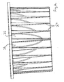
FIGURE 1 is a perspective view of a preferred embodiment of a directionally-adjustable LED spotlight of the present invention oriented if the embodiment were mounted in a ceiling. -
FIGURE 2 is a side view of the fixed heat sink of the embodiment ofFIGURE 1 . -
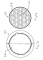
FIGURE 3a is a top view of the fixed heat sink ofFIGURE 2 . -
FIGURE 3b is a side view of the ball portion of the LED-array bearing structure ofFIGURE 1 . -
FIGURE 4a is a top view of the ball portion of the LED-array-bearing structure ofFIGURE 3b . -
FIGURE 4b is a top view of the LED array of the LED-array-bearing structure of the embodiment ofFIGURE 1 . -
FIGURE 1 illustrates a preferred embodiment of a directionally-adjustable LED spotlight 10 of the current invention. TheLED spotlight 10 includes afixed heat sink 20 and an LED-array-bearingstructure 30. As seen inFIGURE 2 , theheat sink 20 is in a socket shape shown in thesocket portion 22 and further includes a plurality offins 24 that extend outwardly from anouter surface 26 of theheat sink 20. - Referring again to
FIGURE 1 , the LED-array-bearingstructure 30 includes aball portion 32 and anLED array 34. As can be seen inFIGURES 3a and 3b , theball portion 32 is sized to fit inside thesocket portion 22 of theheat sink 20. Furthermore, theball portion 32 is made of metal and is hollow. The ball and socket design of theheat sink 20 and the LED-array-bearingstructure 30 allow for the entirety of thesocket portion 22 of theheat sink 20 to be in contact with theball portion 32 of the LED-array-bearingstructure 30. This contact ensures a heat transfer relationship between the two parts. - As shown in
FIGURE 4a theball portion 32 is not completely spherical, rather theball portion 32 includesplatform portion 36 that defines the top of theball portion 32.FIGURE 4b shows theLED array 34 that includes afirst side 38 having a plurality ofLEDs 40 and second side (not shown). As seen inFIGURES 4a and 4b theplatform portion 36 is sized to receive theLED array 34 wherein the second side of theLED 34 array will come in contact with theplatform portion 36. This sizing arrangement allows for efficient heat transfer from theLED array 34 to theball portion 32 whereby heat can be transferred to theheat sink 20 and thefins 24. - Referring again to
FIGURE 1 , theLED spotlight 10 further includes acollar 12 for securing the LED-array-bearingstructure 30 in place. Once the LED-array-bearingstructure 30 has been positioned in theheat sink 20 thecollar 12 fits over the LED-array-bearingstructure 30 and comes in contact with anupper edge 28 of theheat sink 20. Thecollar 12 is then secured using screws or other means and the LED-array-bearingstructure 30 is then secured in place. In other embodiments, not shown, the collar could be divided into sections rather than one piece. To readjust the LED-array-bearingstructure 30 thecollar 12 must simply be loosed and the LED-array-bearingstructure 30 can be rotated to a different angle. - While the principles of the invention have been shown and described in connection with specific embodiments, it is to be understood that such embodiments are by way of example and are not limiting.
Claims (10)
- A directionally-adjustable LED spotlight (10) comprising a fixed heat sink (20), and an LED-array-bearing structure (30) adjustably attached in heat transfer relationship to the fixed heat sink (20),
the LED-array-bearing structure (30) and the heat sink (20) being of a ball and socket design, characterized in that the LED-array-bearing structure (30) is ball-shaped and the heat sink (20) is socket-shaped, allowing for maximum contact between the heat sink (20) and the LED-array-bearing structure (30). - The directionally-adjustable LED spotlight (10) of claim 1 wherein the ball-shaped LED-array-bearing structure (30) is hollow.
- The directionally-adjustable LED spotlight (10) of claim 1 or 2 further comprising a retention assembly for releasably securing the ball-shaped LED-array-bearing structure (30) in relation to the socket-shaped heat sink (20).
- The directionally-adjustable LED spotlight (10) of claim 3 wherein the retention assembly comprises a collar (12) releasably secured along an upper edge of the fixed heat sink (20).
- The directionally-adjustable LED spotlight (10) of claim 4 wherein the collar (12) comprises multiple sections.
- The directionally-adjustable LED spotlight (10) of any of the previous claims, wherein the LED-array-bearing structure (30) comprises a ball portion (32) and an LED array (34) attached to the ball portion (32) and including a plurality of LEDs (40).
- The directionally-adjustable LED spotlight (10) of claim 6, wherein the LED array (34) includes a first side (38) with the LEDs (40) and a second side, opposite the first side (38), and wherein the socket-shaped heat sink (20) includes a platform portion (36) corresponding in size to the second side of the lighting element, the platform portion (36) for receiving the LED array (34) whereby the second side of the LED array (34) is in contact with the platform portion (36).
- The directionally-adjustable LED spotlight (10) of claim 7 where the ball portion (32) of the LED-array-bearing structure (30) and the heat sink (20) are made from a heat-conducting material.
- The directionally-adjustable LED spotlight (10) of claim 8, wherein the heat-conducting material is metal.
- The directionally-adjustable LED spotlight (10) of claim 9, wherein the heat sink (20) includes a plurality of fins (24) extending outwardly from a side of the heat sink (20) opposite the ball-shaped LED-array-bearing structure (30).
Applications Claiming Priority (1)
| Application Number | Priority Date | Filing Date | Title |
|---|---|---|---|
| US11/541,906 US7744259B2 (en) | 2006-09-30 | 2006-09-30 | Directionally-adjustable LED spotlight |
Publications (2)
| Publication Number | Publication Date |
|---|---|
| EP1906078A1 EP1906078A1 (en) | 2008-04-02 |
| EP1906078B1 true EP1906078B1 (en) | 2010-06-16 |
Family
ID=38683001
Family Applications (1)
| Application Number | Title | Priority Date | Filing Date |
|---|---|---|---|
| EP07018276A Active EP1906078B1 (en) | 2006-09-30 | 2007-09-18 | Directionally-adjustable LED spotlight |
Country Status (5)
| Country | Link |
|---|---|
| US (1) | US7744259B2 (en) |
| EP (1) | EP1906078B1 (en) |
| AT (1) | ATE471483T1 (en) |
| CA (1) | CA2602780C (en) |
| DE (1) | DE602007007166D1 (en) |
Families Citing this family (85)
| Publication number | Priority date | Publication date | Assignee | Title |
|---|---|---|---|---|
| US7985005B2 (en) * | 2006-05-30 | 2011-07-26 | Journée Lighting, Inc. | Lighting assembly and light module for same |
| WO2009039491A1 (en) | 2007-09-21 | 2009-03-26 | Cooper Technologies Company | Light emitting diode recessed light fixture |
| US7914902B2 (en) * | 2007-11-06 | 2011-03-29 | Jiing Tung Tec. Metal Co., Ltd. | Thermal module |
| DE102008007647A1 (en) * | 2008-02-06 | 2009-08-13 | Zumtobel Lighting Gmbh | LED light with adjustable light source |
| AT506521B1 (en) * | 2008-02-22 | 2010-06-15 | Hierzer Andreas | LIGHTS PROFILE |
| US7866850B2 (en) * | 2008-02-26 | 2011-01-11 | Journée Lighting, Inc. | Light fixture assembly and LED assembly |
| US8905583B2 (en) * | 2008-06-01 | 2014-12-09 | Jack Guy Dubord | Adjustable light emitting diode lighting assembly, kit and system and method of assembling an adjustable light emitting diode lighting assembly |
| CN201237125Y (en) * | 2008-07-22 | 2009-05-13 | 武良举 | Bulb angle-adjustable lamp |
| IT1392428B1 (en) * | 2008-07-31 | 2012-03-02 | Barbagallo | LED LIGHTING APPLIANCE.- |
| US8152334B2 (en) * | 2008-09-08 | 2012-04-10 | Lsi Industries, Inc. | LED lighting assembly with adjustment means |
| US9374856B2 (en) | 2008-09-23 | 2016-06-21 | Jeffrey Winton | Energy saving undercabinet lighting system using light emitting diodes |
| US9750094B1 (en) | 2008-09-23 | 2017-08-29 | Radionic Industries, Inc. | Energy saving under-cabinet lighting system using light emitting diodes with a USB port |
| KR100901180B1 (en) * | 2008-10-13 | 2009-06-04 | 현대통신 주식회사 | Heat emittimg member having variable heat emitting path and led lighting flood lamp using said it |
| US8342709B2 (en) * | 2008-10-24 | 2013-01-01 | Hubbell Incorporated | Light emitting diode module, and light fixture and method of illumination utilizing the same |
| US8152336B2 (en) | 2008-11-21 | 2012-04-10 | Journée Lighting, Inc. | Removable LED light module for use in a light fixture assembly |
| US8366290B2 (en) * | 2009-01-14 | 2013-02-05 | Mag Instrument, Inc. | Portable lighting device |
| EP2406542B1 (en) * | 2009-03-12 | 2016-03-02 | Koninklijke Philips N.V. | Light emitting device and luminaire |
| US8791499B1 (en) | 2009-05-27 | 2014-07-29 | Soraa, Inc. | GaN containing optical devices and method with ESD stability |
| US8596837B1 (en) | 2009-07-21 | 2013-12-03 | Cooper Technologies Company | Systems, methods, and devices providing a quick-release mechanism for a modular LED light engine |
| WO2011011323A1 (en) | 2009-07-21 | 2011-01-27 | Cooper Technologies Company | Interfacing a light emitting diode (led) module to a heat sink assembly, a light reflector and electrical circuits |
| WO2011011986A1 (en) * | 2009-07-29 | 2011-02-03 | Tung Kuo-Feng | Led light fixture |
| US8104928B1 (en) * | 2009-08-10 | 2012-01-31 | Cannon Safe Inc. | Adjustable direction LED puck light |
| WO2011019945A1 (en) * | 2009-08-12 | 2011-02-17 | Journee Lighting, Inc. | Led light module for use in a lighting assembly |
| US8125776B2 (en) | 2010-02-23 | 2012-02-28 | Journée Lighting, Inc. | Socket and heat sink unit for use with removable LED light module |
| DE202010004776U1 (en) * | 2010-04-09 | 2011-09-02 | Zumtobel Lighting Gmbh | Luminaire with swiveling LED |
| US8803452B2 (en) | 2010-10-08 | 2014-08-12 | Soraa, Inc. | High intensity light source |
| DE102010042287B9 (en) * | 2010-10-11 | 2013-07-11 | Schott Ag | Lighting device, in particular reading light |
| US8133059B1 (en) * | 2010-10-26 | 2012-03-13 | Ming Jen Hsiao | Angle-adjustable night lamp assembly for aroma diffusing night lamp system |
| US8757852B2 (en) | 2010-10-27 | 2014-06-24 | Cree, Inc. | Lighting apparatus |
| US8403533B1 (en) * | 2011-01-28 | 2013-03-26 | Cooper Technologies Company | Adjustable LED module with stationary heat sink |
| US8618742B2 (en) * | 2011-02-11 | 2013-12-31 | Soraa, Inc. | Illumination source and manufacturing methods |
| US10036544B1 (en) | 2011-02-11 | 2018-07-31 | Soraa, Inc. | Illumination source with reduced weight |
| US8525396B2 (en) * | 2011-02-11 | 2013-09-03 | Soraa, Inc. | Illumination source with direct die placement |
| US8643257B2 (en) * | 2011-02-11 | 2014-02-04 | Soraa, Inc. | Illumination source with reduced inner core size |
| CN102691948B (en) | 2011-03-23 | 2016-04-20 | 欧司朗股份有限公司 | Can the Down lamp of multi-direction regulating irradiation angle |
| US8550669B2 (en) * | 2011-05-09 | 2013-10-08 | Schneider Electric USA, Inc. | Adjustable slope ceiling recessed light fixture |
| AU2011100724A4 (en) * | 2011-06-10 | 2011-08-25 | Gerard Lighting Pty Ltd | The present invention relates to downlights, and in one form, to downlights where the angle of the downlight can be easily adjusted |
| US9752739B2 (en) | 2011-08-29 | 2017-09-05 | Hubbell Incorporated | Emergency lighting assembly having heat conducting member |
| US9488324B2 (en) | 2011-09-02 | 2016-11-08 | Soraa, Inc. | Accessories for LED lamp systems |
| US9109760B2 (en) | 2011-09-02 | 2015-08-18 | Soraa, Inc. | Accessories for LED lamps |
| CN102374463A (en) * | 2011-10-11 | 2012-03-14 | 山水照明科技(常熟)有限公司 | LED (Light-Emitting Diode) barrel lamp |
| US8884517B1 (en) | 2011-10-17 | 2014-11-11 | Soraa, Inc. | Illumination sources with thermally-isolated electronics |
| US9109787B2 (en) * | 2012-01-25 | 2015-08-18 | Hubbell Incorporated | Circular LED optic and heat sink module |
| US8985794B1 (en) | 2012-04-17 | 2015-03-24 | Soraa, Inc. | Providing remote blue phosphors in an LED lamp |
| USD728849S1 (en) | 2012-05-03 | 2015-05-05 | Lumenpulse Lighting Inc. | LED projection fixture |
| US9995439B1 (en) | 2012-05-14 | 2018-06-12 | Soraa, Inc. | Glare reduced compact lens for high intensity light source |
| US9360190B1 (en) | 2012-05-14 | 2016-06-07 | Soraa, Inc. | Compact lens for high intensity light source |
| US10436422B1 (en) | 2012-05-14 | 2019-10-08 | Soraa, Inc. | Multi-function active accessories for LED lamps |
| US9310052B1 (en) | 2012-09-28 | 2016-04-12 | Soraa, Inc. | Compact lens for high intensity light source |
| DE102012106314A1 (en) * | 2012-07-13 | 2014-01-16 | Hella Kgaa Hueck & Co. | Module assembly with pivotable semiconductor light modules for a headlight |
| US9215764B1 (en) | 2012-11-09 | 2015-12-15 | Soraa, Inc. | High-temperature ultra-low ripple multi-stage LED driver and LED control circuits |
| ITMI20130079A1 (en) * | 2013-01-22 | 2014-07-23 | Castaldi Lighting Societa A Respon Sabilita Limi | STRUCTURE OF ADJUSTABLE SUPPORT WITH HIGH CAPACITY OF THERMAL DISSIPATION, PARTICULARLY FOR THE INSTALLATION OF LIGHTING EQUIPMENT. |
| US9565782B2 (en) | 2013-02-15 | 2017-02-07 | Ecosense Lighting Inc. | Field replaceable power supply cartridge |
| US9267661B1 (en) | 2013-03-01 | 2016-02-23 | Soraa, Inc. | Apportioning optical projection paths in an LED lamp |
| US9435525B1 (en) | 2013-03-08 | 2016-09-06 | Soraa, Inc. | Multi-part heat exchanger for LED lamps |
| US10048429B2 (en) | 2013-09-26 | 2018-08-14 | The Regents Of The University Of California | Illuminator with adjustable beam direction and divergence |
| US9182093B2 (en) | 2013-12-20 | 2015-11-10 | Evolution Lighting, Llc | Gimbaled ceiling lamp |
| US9657933B2 (en) | 2014-02-03 | 2017-05-23 | Abl Ip Holding Llc | Interlaced heat sink for recessed light |
| US9851081B2 (en) * | 2014-02-03 | 2017-12-26 | Abl Ip Holding Llc | Wedge shaped heat sink for gimbal mounted solid state recessed lighting |
| CN104930414B (en) * | 2014-03-19 | 2018-03-06 | 欧普照明股份有限公司 | A kind of lighting device |
| USD745207S1 (en) * | 2014-03-21 | 2015-12-08 | Iguzzini Illuminazione S.P.A. | Lighting apparatus |
| US9447953B2 (en) | 2014-05-30 | 2016-09-20 | Generation Brands Llc | Adjustable luminaire |
| USD744156S1 (en) * | 2014-06-25 | 2015-11-24 | Martin Professional Aps | Light lens |
| WO2016007018A1 (en) * | 2014-07-11 | 2016-01-14 | Switch Lighting Limited | Improvements in and relating to lighting fixtures |
| US9581322B2 (en) * | 2014-09-30 | 2017-02-28 | Aeonovalite Technologies, Inc. | Heat-sink for high bay LED device, high bay LED device and methods of use thereof |
| US10477636B1 (en) | 2014-10-28 | 2019-11-12 | Ecosense Lighting Inc. | Lighting systems having multiple light sources |
| US9869450B2 (en) | 2015-02-09 | 2018-01-16 | Ecosense Lighting Inc. | Lighting systems having a truncated parabolic- or hyperbolic-conical light reflector, or a total internal reflection lens; and having another light reflector |
| US11306897B2 (en) | 2015-02-09 | 2022-04-19 | Ecosense Lighting Inc. | Lighting systems generating partially-collimated light emissions |
| US9651216B2 (en) | 2015-03-03 | 2017-05-16 | Ecosense Lighting Inc. | Lighting systems including asymmetric lens modules for selectable light distribution |
| US9651227B2 (en) | 2015-03-03 | 2017-05-16 | Ecosense Lighting Inc. | Low-profile lighting system having pivotable lighting enclosure |
| US9568665B2 (en) | 2015-03-03 | 2017-02-14 | Ecosense Lighting Inc. | Lighting systems including lens modules for selectable light distribution |
| US9746159B1 (en) | 2015-03-03 | 2017-08-29 | Ecosense Lighting Inc. | Lighting system having a sealing system |
| USD785218S1 (en) | 2015-07-06 | 2017-04-25 | Ecosense Lighting Inc. | LED luminaire having a mounting system |
| USD863607S1 (en) | 2015-07-07 | 2019-10-15 | Auroralight, Inc. | Ball and socket heat exchanger for a light fixture |
| USD782093S1 (en) | 2015-07-20 | 2017-03-21 | Ecosense Lighting Inc. | LED luminaire having a mounting system |
| USD782094S1 (en) | 2015-07-20 | 2017-03-21 | Ecosense Lighting Inc. | LED luminaire having a mounting system |
| US9651232B1 (en) | 2015-08-03 | 2017-05-16 | Ecosense Lighting Inc. | Lighting system having a mounting device |
| CN206093753U (en) * | 2016-09-28 | 2017-04-12 | 佛山市威得士灯饰电器有限公司 | Lamps and lanterns of adjustable illumination angle |
| USD864880S1 (en) * | 2018-02-06 | 2019-10-29 | Soraa, Inc. | Heatsink with hinge |
| USD873224S1 (en) * | 2018-02-06 | 2020-01-21 | Soraa, Inc. | Heatsink |
| USD874715S1 (en) | 2018-03-07 | 2020-02-04 | Myotek Holdings, Inc. | LED spot lamp lens |
| CN209294980U (en) * | 2019-01-25 | 2019-08-23 | 深圳市冠科科技有限公司 | A kind of electric light source device that multi-angle is luminous |
| WO2020187831A1 (en) * | 2019-03-21 | 2020-09-24 | Signify Holding B.V. | An adjustable light source holder, a directable spotlight and a manufacture method thereof |
| USD983864S1 (en) | 2019-09-10 | 2023-04-18 | Arnold & Richter Cine Technik Gmbh & Co. Betriebs Kg | Control panel for headlight |
| KR20220146109A (en) * | 2021-04-23 | 2022-11-01 | 현대자동차주식회사 | Structure and method for utilizing indoor natural light in moving space |
Family Cites Families (44)
| Publication number | Priority date | Publication date | Assignee | Title |
|---|---|---|---|---|
| US1739641A (en) * | 1928-02-18 | 1929-12-17 | Herbert F Lessmann | Portable and adjustable light |
| US3912918A (en) * | 1974-04-22 | 1975-10-14 | Designs For Vision | Light sources employing universally adjustable ball and socket joints |
| US3950639A (en) | 1974-10-16 | 1976-04-13 | Westinghouse Electric Corporation | High beam low brightness luminaire |
| US4298912A (en) * | 1979-10-09 | 1981-11-03 | Dearth Miles B | Attachment for a vehicle dome light |
| US4330814A (en) | 1980-04-04 | 1982-05-18 | General Electric Company | Floor relampable luminaire |
| US4750096A (en) | 1987-01-13 | 1988-06-07 | Lumatech Corp. | Fluorescent light fixture |
| US4872097A (en) | 1988-12-05 | 1989-10-03 | Miller Jack V | Miniature low-voltage lighting fixture |
| US5486989A (en) | 1993-11-12 | 1996-01-23 | Kim Lighting, Inc. | Luminaire with modular louver shields |
| US5434765A (en) | 1994-03-10 | 1995-07-18 | Holophane Corporation | Luminaire assembly |
| USD384769S (en) | 1994-12-14 | 1997-10-07 | U.S. Philips Corporation | Reflector unit for fluorescent lighting fixture |
| US5690424A (en) | 1995-05-08 | 1997-11-25 | Justice Design Group, Inc. | Mounting apparatus for lighting fixtures |
| US5672004A (en) * | 1996-09-03 | 1997-09-30 | Imo Industries, Inc. | Lighting apparatus and related method |
| US6029939A (en) | 1998-11-06 | 2000-02-29 | Mei Darl Li Duster Co., Ltd. | Duster pedestal |
| US6367949B1 (en) | 1999-08-04 | 2002-04-09 | 911 Emergency Products, Inc. | Par 36 LED utility lamp |
| US6565238B1 (en) | 2000-06-23 | 2003-05-20 | H. E. Williams, Inc. | Fluorescent light fixture with lateral ballast |
| US6350043B1 (en) * | 2000-07-21 | 2002-02-26 | Aerospace Lighting Corporation | Behind panel mount, directional lighting bracket |
| DE10044146A1 (en) * | 2000-09-06 | 2002-03-14 | Hella Aerospace Gmbh | Light for vehicles |
| US6846933B1 (en) | 2000-10-30 | 2005-01-25 | The Board Of Trustees Of Wellesley College | Antimycobacterial compounds and method for making the same |
| US6877709B2 (en) * | 2000-12-21 | 2005-04-12 | Donnelly Corporation | Interior rearview mirror assembly with polymeric components |
| WO2002097884A1 (en) | 2001-05-26 | 2002-12-05 | Gelcore, Llc | High power led module for spot illumination |
| US6386274B1 (en) | 2001-06-28 | 2002-05-14 | Foxconn Precision Components Co., Ltd. | Heat sink assembly |
| USD464938S1 (en) | 2001-07-27 | 2002-10-29 | Hewlett Packard Company | High performance cooling device |
| US6871983B2 (en) | 2001-10-25 | 2005-03-29 | Tir Systems Ltd. | Solid state continuous sealed clean room light fixture |
| ITMI20012579A1 (en) | 2001-12-06 | 2003-06-06 | Fraen Corp Srl | HIGH HEAT DISSIPATION ILLUMINATING MODULE |
| US7011431B2 (en) * | 2002-04-23 | 2006-03-14 | Nichia Corporation | Lighting apparatus |
| US6997583B2 (en) * | 2002-05-10 | 2006-02-14 | Goodrich Hella Aerospace Lighting Systems Gmbh | Lamp for a vehicle, in particular reading lamp for an aircraft |
| US6720566B2 (en) | 2002-08-20 | 2004-04-13 | Miltec Corporation | Shutter for use with a light source |
| US6787999B2 (en) | 2002-10-03 | 2004-09-07 | Gelcore, Llc | LED-based modular lamp |
| US6964501B2 (en) | 2002-12-24 | 2005-11-15 | Altman Stage Lighting Co., Ltd. | Peltier-cooled LED lighting assembly |
| ITTO20030165A1 (en) | 2003-03-06 | 2004-09-07 | Space Cannon Vh S P A | LED LIGHT PROJECTOR |
| US6910794B2 (en) | 2003-04-25 | 2005-06-28 | Guide Corporation | Automotive lighting assembly cooling system |
| US6880956B2 (en) | 2003-07-31 | 2005-04-19 | A L Lightech, Inc. | Light source with heat transfer arrangement |
| US6955451B2 (en) | 2003-08-25 | 2005-10-18 | Osram Sylvania Inc. | Lamp with LED substrates supported by heat conductive post, and method of making such lamp |
| US7097332B2 (en) | 2003-09-05 | 2006-08-29 | Gabor Vamberi | Light fixture with fins |
| EP1521031A3 (en) | 2003-09-30 | 2008-02-27 | Toshiba Lighting & Technology Corporation | Light emitting diode lighting appliance and light emitting diode emergency light using the same |
| US6982518B2 (en) | 2003-10-01 | 2006-01-03 | Enertron, Inc. | Methods and apparatus for an LED light |
| JP2005129354A (en) | 2003-10-23 | 2005-05-19 | Toshiba Lighting & Technology Corp | Led lighting device |
| JP2006004863A (en) | 2004-06-21 | 2006-01-05 | Toshiba Lighting & Technology Corp | Light-emitting diode type spotlight |
| JP4661292B2 (en) | 2004-06-21 | 2011-03-30 | 東芝ライテック株式会社 | Lighting device and LED spotlight |
| JP4331077B2 (en) | 2004-09-10 | 2009-09-16 | 日本放送協会 | LED light source device and spotlight |
| USD525374S1 (en) | 2005-02-28 | 2006-07-18 | Lighting Science Group Corporation | Floodlight |
| US20060262542A1 (en) * | 2005-05-18 | 2006-11-23 | Jji Lighting Group, Inc. | Modular landscape light fixture |
| USD527119S1 (en) | 2005-07-27 | 2006-08-22 | Lighting Science Group Corporation | LED light bulb |
| USD528673S1 (en) | 2005-07-27 | 2006-09-19 | Lighting Science Group Corporation | LED light bulb |
-
2006
- 2006-09-30 US US11/541,906 patent/US7744259B2/en active Active
-
2007
- 2007-09-18 DE DE602007007166T patent/DE602007007166D1/en active Active
- 2007-09-18 CA CA2602780A patent/CA2602780C/en active Active
- 2007-09-18 AT AT07018276T patent/ATE471483T1/en not_active IP Right Cessation
- 2007-09-18 EP EP07018276A patent/EP1906078B1/en active Active
Also Published As
| Publication number | Publication date |
|---|---|
| CA2602780A1 (en) | 2008-03-30 |
| US20080080190A1 (en) | 2008-04-03 |
| ATE471483T1 (en) | 2010-07-15 |
| DE602007007166D1 (en) | 2010-07-29 |
| CA2602780C (en) | 2014-06-17 |
| US7744259B2 (en) | 2010-06-29 |
| EP1906078A1 (en) | 2008-04-02 |
Similar Documents
| Publication | Publication Date | Title |
|---|---|---|
| EP1906078B1 (en) | Directionally-adjustable LED spotlight | |
| US9995462B2 (en) | Circular LED optic and heat sink module | |
| US7048412B2 (en) | Axial LED source | |
| US8480264B2 (en) | Lighting apparatus with heat dissipation system | |
| US5690424A (en) | Mounting apparatus for lighting fixtures | |
| CN101922693A (en) | Luminaire | |
| JP2010198828A (en) | Lighting device | |
| JP2007172932A (en) | Vehicular headlight | |
| JP4103437B2 (en) | Lighting device | |
| JP4674269B1 (en) | Light bulb shaped LED lamp and lighting apparatus | |
| JP6206114B2 (en) | lamp | |
| JP2011187296A (en) | Lighting system | |
| US9523468B2 (en) | Lighting fixture having enhanced light distribution performance | |
| JP6176212B2 (en) | Light emitting device | |
| KR101927618B1 (en) | Led lighting devices | |
| CN103791272A (en) | Illuminating device with large vision angle | |
| JP6149832B2 (en) | Light emitting device | |
| JP6044610B2 (en) | Light emitting device | |
| KR101325098B1 (en) | Lighting unit | |
| JP6090267B2 (en) | Light emitting device | |
| EP2743128B1 (en) | Lighting apparatus having angle indicating means | |
| CN101487582B (en) | LED lamp | |
| JP2016004602A (en) | Lighting device | |
| JP6375247B2 (en) | lighting equipment | |
| JP2015228348A (en) | Illumination device |
Legal Events
| Date | Code | Title | Description |
|---|---|---|---|
| PUAI | Public reference made under article 153(3) epc to a published international application that has entered the european phase |
Free format text: ORIGINAL CODE: 0009012 |
|
| AK | Designated contracting states |
Kind code of ref document: A1 Designated state(s): AT BE BG CH CY CZ DE DK EE ES FI FR GB GR HU IE IS IT LI LT LU LV MC MT NL PL PT RO SE SI SK TR |
|
| AX | Request for extension of the european patent |
Extension state: AL BA HR MK YU |
|
| 17P | Request for examination filed |
Effective date: 20080924 |
|
| 17Q | First examination report despatched |
Effective date: 20081024 |
|
| AKX | Designation fees paid |
Designated state(s): AT BE BG CH CY CZ DE DK EE ES FI FR GB GR HU IE IS IT LI LT LU LV MC MT NL PL PT RO SE SI SK TR |
|
| GRAP | Despatch of communication of intention to grant a patent |
Free format text: ORIGINAL CODE: EPIDOSNIGR1 |
|
| GRAS | Grant fee paid |
Free format text: ORIGINAL CODE: EPIDOSNIGR3 |
|
| GRAA | (expected) grant |
Free format text: ORIGINAL CODE: 0009210 |
|
| AK | Designated contracting states |
Kind code of ref document: B1 Designated state(s): AT BE BG CH CY CZ DE DK EE ES FI FR GB GR HU IE IS IT LI LT LU LV MC MT NL PL PT RO SE SI SK TR |
|
| REG | Reference to a national code |
Ref country code: CH Ref legal event code: EP |
|
| REG | Reference to a national code |
Ref country code: IE Ref legal event code: FG4D |
|
| REF | Corresponds to: |
Ref document number: 602007007166 Country of ref document: DE Date of ref document: 20100729 Kind code of ref document: P |
|
| REG | Reference to a national code |
Ref country code: NL Ref legal event code: VDEP Effective date: 20100616 |
|
| PG25 | Lapsed in a contracting state [announced via postgrant information from national office to epo] |
Ref country code: SE Free format text: LAPSE BECAUSE OF FAILURE TO SUBMIT A TRANSLATION OF THE DESCRIPTION OR TO PAY THE FEE WITHIN THE PRESCRIBED TIME-LIMIT Effective date: 20100616 Ref country code: LT Free format text: LAPSE BECAUSE OF FAILURE TO SUBMIT A TRANSLATION OF THE DESCRIPTION OR TO PAY THE FEE WITHIN THE PRESCRIBED TIME-LIMIT Effective date: 20100616 |
|
| LTIE | Lt: invalidation of european patent or patent extension |
Effective date: 20100616 |
|
| PG25 | Lapsed in a contracting state [announced via postgrant information from national office to epo] |
Ref country code: AT Free format text: LAPSE BECAUSE OF FAILURE TO SUBMIT A TRANSLATION OF THE DESCRIPTION OR TO PAY THE FEE WITHIN THE PRESCRIBED TIME-LIMIT Effective date: 20100616 Ref country code: LV Free format text: LAPSE BECAUSE OF FAILURE TO SUBMIT A TRANSLATION OF THE DESCRIPTION OR TO PAY THE FEE WITHIN THE PRESCRIBED TIME-LIMIT Effective date: 20100616 Ref country code: SI Free format text: LAPSE BECAUSE OF FAILURE TO SUBMIT A TRANSLATION OF THE DESCRIPTION OR TO PAY THE FEE WITHIN THE PRESCRIBED TIME-LIMIT Effective date: 20100616 Ref country code: FI Free format text: LAPSE BECAUSE OF FAILURE TO SUBMIT A TRANSLATION OF THE DESCRIPTION OR TO PAY THE FEE WITHIN THE PRESCRIBED TIME-LIMIT Effective date: 20100616 |
|
| PG25 | Lapsed in a contracting state [announced via postgrant information from national office to epo] |
Ref country code: PL Free format text: LAPSE BECAUSE OF FAILURE TO SUBMIT A TRANSLATION OF THE DESCRIPTION OR TO PAY THE FEE WITHIN THE PRESCRIBED TIME-LIMIT Effective date: 20100616 Ref country code: CY Free format text: LAPSE BECAUSE OF FAILURE TO SUBMIT A TRANSLATION OF THE DESCRIPTION OR TO PAY THE FEE WITHIN THE PRESCRIBED TIME-LIMIT Effective date: 20100616 |
|
| PG25 | Lapsed in a contracting state [announced via postgrant information from national office to epo] |
Ref country code: EE Free format text: LAPSE BECAUSE OF FAILURE TO SUBMIT A TRANSLATION OF THE DESCRIPTION OR TO PAY THE FEE WITHIN THE PRESCRIBED TIME-LIMIT Effective date: 20100616 Ref country code: NL Free format text: LAPSE BECAUSE OF FAILURE TO SUBMIT A TRANSLATION OF THE DESCRIPTION OR TO PAY THE FEE WITHIN THE PRESCRIBED TIME-LIMIT Effective date: 20100616 Ref country code: GR Free format text: LAPSE BECAUSE OF FAILURE TO SUBMIT A TRANSLATION OF THE DESCRIPTION OR TO PAY THE FEE WITHIN THE PRESCRIBED TIME-LIMIT Effective date: 20100917 |
|
| PG25 | Lapsed in a contracting state [announced via postgrant information from national office to epo] |
Ref country code: BE Free format text: LAPSE BECAUSE OF FAILURE TO SUBMIT A TRANSLATION OF THE DESCRIPTION OR TO PAY THE FEE WITHIN THE PRESCRIBED TIME-LIMIT Effective date: 20100616 Ref country code: SK Free format text: LAPSE BECAUSE OF FAILURE TO SUBMIT A TRANSLATION OF THE DESCRIPTION OR TO PAY THE FEE WITHIN THE PRESCRIBED TIME-LIMIT Effective date: 20100616 Ref country code: PT Free format text: LAPSE BECAUSE OF FAILURE TO SUBMIT A TRANSLATION OF THE DESCRIPTION OR TO PAY THE FEE WITHIN THE PRESCRIBED TIME-LIMIT Effective date: 20101018 Ref country code: RO Free format text: LAPSE BECAUSE OF FAILURE TO SUBMIT A TRANSLATION OF THE DESCRIPTION OR TO PAY THE FEE WITHIN THE PRESCRIBED TIME-LIMIT Effective date: 20100616 Ref country code: CZ Free format text: LAPSE BECAUSE OF FAILURE TO SUBMIT A TRANSLATION OF THE DESCRIPTION OR TO PAY THE FEE WITHIN THE PRESCRIBED TIME-LIMIT Effective date: 20100616 Ref country code: IS Free format text: LAPSE BECAUSE OF FAILURE TO SUBMIT A TRANSLATION OF THE DESCRIPTION OR TO PAY THE FEE WITHIN THE PRESCRIBED TIME-LIMIT Effective date: 20101016 |
|
| PLBE | No opposition filed within time limit |
Free format text: ORIGINAL CODE: 0009261 |
|
| STAA | Information on the status of an ep patent application or granted ep patent |
Free format text: STATUS: NO OPPOSITION FILED WITHIN TIME LIMIT |
|
| PG25 | Lapsed in a contracting state [announced via postgrant information from national office to epo] |
Ref country code: MC Free format text: LAPSE BECAUSE OF NON-PAYMENT OF DUE FEES Effective date: 20100930 Ref country code: DK Free format text: LAPSE BECAUSE OF FAILURE TO SUBMIT A TRANSLATION OF THE DESCRIPTION OR TO PAY THE FEE WITHIN THE PRESCRIBED TIME-LIMIT Effective date: 20100616 |
|
| 26N | No opposition filed |
Effective date: 20110317 |
|
| REG | Reference to a national code |
Ref country code: DE Ref legal event code: R097 Ref document number: 602007007166 Country of ref document: DE Effective date: 20110316 |
|
| PG25 | Lapsed in a contracting state [announced via postgrant information from national office to epo] |
Ref country code: IE Free format text: LAPSE BECAUSE OF NON-PAYMENT OF DUE FEES Effective date: 20100918 |
|
| PG25 | Lapsed in a contracting state [announced via postgrant information from national office to epo] |
Ref country code: MT Free format text: LAPSE BECAUSE OF FAILURE TO SUBMIT A TRANSLATION OF THE DESCRIPTION OR TO PAY THE FEE WITHIN THE PRESCRIBED TIME-LIMIT Effective date: 20100616 |
|
| REG | Reference to a national code |
Ref country code: CH Ref legal event code: PL |
|
| PG25 | Lapsed in a contracting state [announced via postgrant information from national office to epo] |
Ref country code: LI Free format text: LAPSE BECAUSE OF NON-PAYMENT OF DUE FEES Effective date: 20110930 Ref country code: CH Free format text: LAPSE BECAUSE OF NON-PAYMENT OF DUE FEES Effective date: 20110930 |
|
| PG25 | Lapsed in a contracting state [announced via postgrant information from national office to epo] |
Ref country code: LU Free format text: LAPSE BECAUSE OF NON-PAYMENT OF DUE FEES Effective date: 20100918 Ref country code: BG Free format text: LAPSE BECAUSE OF FAILURE TO SUBMIT A TRANSLATION OF THE DESCRIPTION OR TO PAY THE FEE WITHIN THE PRESCRIBED TIME-LIMIT Effective date: 20100616 Ref country code: HU Free format text: LAPSE BECAUSE OF FAILURE TO SUBMIT A TRANSLATION OF THE DESCRIPTION OR TO PAY THE FEE WITHIN THE PRESCRIBED TIME-LIMIT Effective date: 20101217 |
|
| PG25 | Lapsed in a contracting state [announced via postgrant information from national office to epo] |
Ref country code: TR Free format text: LAPSE BECAUSE OF FAILURE TO SUBMIT A TRANSLATION OF THE DESCRIPTION OR TO PAY THE FEE WITHIN THE PRESCRIBED TIME-LIMIT Effective date: 20100616 |
|
| REG | Reference to a national code |
Ref country code: DE Ref legal event code: R082 Ref document number: 602007007166 Country of ref document: DE Representative=s name: KROHER - STROBEL RECHTS- UND PATENTANWAELTE, DE Effective date: 20130725 Ref country code: DE Ref legal event code: R081 Ref document number: 602007007166 Country of ref document: DE Owner name: CREE, INC., US Free format text: FORMER OWNER: RUUD LIGHTING, INC., RACINE, US Effective date: 20130725 Ref country code: DE Ref legal event code: R081 Ref document number: 602007007166 Country of ref document: DE Owner name: CREE, INC., DURHAM, US Free format text: FORMER OWNER: RUUD LIGHTING, INC., RACINE, WIS., US Effective date: 20130725 Ref country code: DE Ref legal event code: R082 Ref document number: 602007007166 Country of ref document: DE Representative=s name: KROHER - STROBEL RECHTS- UND PATENTANWAELTE PA, DE Effective date: 20130725 |
|
| PG25 | Lapsed in a contracting state [announced via postgrant information from national office to epo] |
Ref country code: BG Free format text: LAPSE BECAUSE OF FAILURE TO SUBMIT A TRANSLATION OF THE DESCRIPTION OR TO PAY THE FEE WITHIN THE PRESCRIBED TIME-LIMIT Effective date: 20100916 |
|
| REG | Reference to a national code |
Ref country code: GB Ref legal event code: 732E Free format text: REGISTERED BETWEEN 20130905 AND 20130911 |
|
| PG25 | Lapsed in a contracting state [announced via postgrant information from national office to epo] |
Ref country code: ES Free format text: LAPSE BECAUSE OF FAILURE TO SUBMIT A TRANSLATION OF THE DESCRIPTION OR TO PAY THE FEE WITHIN THE PRESCRIBED TIME-LIMIT Effective date: 20100927 |
|
| REG | Reference to a national code |
Ref country code: FR Ref legal event code: TP Owner name: CREE, INC., US Effective date: 20131009 |
|
| REG | Reference to a national code |
Ref country code: FR Ref legal event code: PLFP Year of fee payment: 10 |
|
| REG | Reference to a national code |
Ref country code: FR Ref legal event code: PLFP Year of fee payment: 11 |
|
| REG | Reference to a national code |
Ref country code: FR Ref legal event code: PLFP Year of fee payment: 12 |
|
| REG | Reference to a national code |
Ref country code: DE Ref legal event code: R082 Ref document number: 602007007166 Country of ref document: DE Representative=s name: KROHER - STROBEL RECHTS- UND PATENTANWAELTE PA, DE Ref country code: DE Ref legal event code: R081 Ref document number: 602007007166 Country of ref document: DE Owner name: IDEAL INDUSTRIES LIGHTING LLC, SYCAMORE, US Free format text: FORMER OWNER: CREE, INC., DURHAM, N.C., US Ref country code: DE Ref legal event code: R082 Ref document number: 602007007166 Country of ref document: DE Representative=s name: KROHER STROBEL RECHTS- UND PATENTANWAELTE PART, DE |
|
| REG | Reference to a national code |
Ref country code: GB Ref legal event code: 732E Free format text: REGISTERED BETWEEN 20200305 AND 20200311 |
|
| PGFP | Annual fee paid to national office [announced via postgrant information from national office to epo] |
Ref country code: GB Payment date: 20220927 Year of fee payment: 16 |
|
| PGFP | Annual fee paid to national office [announced via postgrant information from national office to epo] |
Ref country code: FR Payment date: 20220926 Year of fee payment: 16 |
|
| PGFP | Annual fee paid to national office [announced via postgrant information from national office to epo] |
Ref country code: IT Payment date: 20220926 Year of fee payment: 16 |
|
| PGFP | Annual fee paid to national office [announced via postgrant information from national office to epo] |
Ref country code: DE Payment date: 20230927 Year of fee payment: 17 |