EP1906093A2 - Method for control of thermoacoustic instabilities in a combustor - Google Patents
Method for control of thermoacoustic instabilities in a combustor Download PDFInfo
- Publication number
- EP1906093A2 EP1906093A2 EP07253776A EP07253776A EP1906093A2 EP 1906093 A2 EP1906093 A2 EP 1906093A2 EP 07253776 A EP07253776 A EP 07253776A EP 07253776 A EP07253776 A EP 07253776A EP 1906093 A2 EP1906093 A2 EP 1906093A2
- Authority
- EP
- European Patent Office
- Prior art keywords
- fuel
- combustor
- uniform
- air
- temperature distribution
- Prior art date
- Legal status (The legal status is an assumption and is not a legal conclusion. Google has not performed a legal analysis and makes no representation as to the accuracy of the status listed.)
- Granted
Links
- 238000000034 method Methods 0.000 title claims abstract description 59
- 239000000446 fuel Substances 0.000 claims description 177
- 230000000694 effects Effects 0.000 claims description 10
- 238000002485 combustion reaction Methods 0.000 description 101
- 238000013016 damping Methods 0.000 description 11
- 238000010586 diagram Methods 0.000 description 10
- 230000007423 decrease Effects 0.000 description 9
- 230000009286 beneficial effect Effects 0.000 description 7
- 230000003247 decreasing effect Effects 0.000 description 6
- 238000009987 spinning Methods 0.000 description 5
- 230000003044 adaptive effect Effects 0.000 description 4
- 238000013459 approach Methods 0.000 description 4
- 230000010355 oscillation Effects 0.000 description 4
- 230000003416 augmentation Effects 0.000 description 3
- 239000007789 gas Substances 0.000 description 3
- 230000001629 suppression Effects 0.000 description 3
- 230000008901 benefit Effects 0.000 description 2
- 230000008859 change Effects 0.000 description 2
- 239000000567 combustion gas Substances 0.000 description 2
- 230000001627 detrimental effect Effects 0.000 description 2
- 230000003993 interaction Effects 0.000 description 2
- 230000003534 oscillatory effect Effects 0.000 description 2
- 238000010791 quenching Methods 0.000 description 2
- 230000001010 compromised effect Effects 0.000 description 1
- 230000008878 coupling Effects 0.000 description 1
- 238000010168 coupling process Methods 0.000 description 1
- 238000005859 coupling reaction Methods 0.000 description 1
- 230000001419 dependent effect Effects 0.000 description 1
- 230000000368 destabilizing effect Effects 0.000 description 1
- 230000000977 initiatory effect Effects 0.000 description 1
- 238000013178 mathematical model Methods 0.000 description 1
- 230000007246 mechanism Effects 0.000 description 1
- 239000000203 mixture Substances 0.000 description 1
- 230000000704 physical effect Effects 0.000 description 1
- 230000004044 response Effects 0.000 description 1
- 238000007493 shaping process Methods 0.000 description 1
- 230000006641 stabilisation Effects 0.000 description 1
- 238000011105 stabilization Methods 0.000 description 1
Images


Classifications
-
- F—MECHANICAL ENGINEERING; LIGHTING; HEATING; WEAPONS; BLASTING
- F23—COMBUSTION APPARATUS; COMBUSTION PROCESSES
- F23R—GENERATING COMBUSTION PRODUCTS OF HIGH PRESSURE OR HIGH VELOCITY, e.g. GAS-TURBINE COMBUSTION CHAMBERS
- F23R3/00—Continuous combustion chambers using liquid or gaseous fuel
- F23R3/28—Continuous combustion chambers using liquid or gaseous fuel characterised by the fuel supply
- F23R3/34—Feeding into different combustion zones
-
- F—MECHANICAL ENGINEERING; LIGHTING; HEATING; WEAPONS; BLASTING
- F23—COMBUSTION APPARATUS; COMBUSTION PROCESSES
- F23M—CASINGS, LININGS, WALLS OR DOORS SPECIALLY ADAPTED FOR COMBUSTION CHAMBERS, e.g. FIREBRIDGES; DEVICES FOR DEFLECTING AIR, FLAMES OR COMBUSTION PRODUCTS IN COMBUSTION CHAMBERS; SAFETY ARRANGEMENTS SPECIALLY ADAPTED FOR COMBUSTION APPARATUS; DETAILS OF COMBUSTION CHAMBERS, NOT OTHERWISE PROVIDED FOR
- F23M20/00—Details of combustion chambers, not otherwise provided for, e.g. means for storing heat from flames
- F23M20/005—Noise absorbing means
-
- F—MECHANICAL ENGINEERING; LIGHTING; HEATING; WEAPONS; BLASTING
- F23—COMBUSTION APPARATUS; COMBUSTION PROCESSES
- F23R—GENERATING COMBUSTION PRODUCTS OF HIGH PRESSURE OR HIGH VELOCITY, e.g. GAS-TURBINE COMBUSTION CHAMBERS
- F23R3/00—Continuous combustion chambers using liquid or gaseous fuel
- F23R3/42—Continuous combustion chambers using liquid or gaseous fuel characterised by the arrangement or form of the flame tubes or combustion chambers
- F23R3/50—Combustion chambers comprising an annular flame tube within an annular casing
-
- F—MECHANICAL ENGINEERING; LIGHTING; HEATING; WEAPONS; BLASTING
- F23—COMBUSTION APPARATUS; COMBUSTION PROCESSES
- F23R—GENERATING COMBUSTION PRODUCTS OF HIGH PRESSURE OR HIGH VELOCITY, e.g. GAS-TURBINE COMBUSTION CHAMBERS
- F23R2900/00—Special features of, or arrangements for continuous combustion chambers; Combustion processes therefor
- F23R2900/00014—Reducing thermo-acoustic vibrations by passive means, e.g. by Helmholtz resonators
Definitions
- the present invention relates generally to gas turbine engines. More particularly, the present invention relates to a method for controlling thermoacoustic instabilities in a combustor.
- thermoacoustic instabilities arise in gas turbine and aero-engines when acoustic modes couple with unsteady heat released due to combustion in a positive feedback loop. These instabilities can lead to large pressure oscillations inside the combustor cavity, thereby affecting its stable operation and potentially causing structural damage to the combustor components.
- Two particular examples of thermoacoustic instabilities in annular combustors are the "screech" instability in the afterburner and the "howl" instability in the primary combustion chamber.
- thermoacoustic instabilities typically utilized passive liners or tuned resonators configured to damp the acoustic mode.
- passive liners or tuned resonators configured to damp the acoustic mode.
- resonators are effective only over a limited range of frequencies and become ineffective if the frequency of the instability changes because of, for example, changes in operating conditions.
- passive devices have to be cooled, which may detrimentally affect the efficiency of the engine.
- effective tuned resonator design requires a prior knowledge of the frequency of instability.
- Active combustion control has also been considered as an approach for control of thermoacoustic instabilities. Active approaches usually require an accurate mathematical model of the thermoacoustic dynamics for control design. However, on account of complex combustion physics, the exact physical mechanism underlying the initiation and sustenance of instabilities such as screech typically is not understood. Furthermore, there are implementation issues such as lack of suitable bandwidth fuel valves that are needed for active control.
- thermoacoustic instabilities typically appear only during a small portion of an aero-engine's flight envelope or operating conditions in the case of land-based combustors.
- passive dampers and active control systems are useful to help control thermoacoustic oscillations only over a small portion of operating conditions and have no useful function at nominal operating conditions.
- they negatively affect weight and performance of the engine at the operating conditions where the instability is not present.
- the present invention in one aspect is a method for controlling a temperature distribution within a combustor having a plurality of chamber sections comprising controlling a fuel-to-air ratio in the chamber sections. At least two chamber sections have different fuel-to-air ratios to create a non-uniform temperature distribution within the combustor to reduce thermoacoustic instabilities.
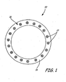
- FIG. 1 is a diagram illustrating an end view of an annular combustor 10 of an aircraft engine having bulkhead section 14. Attached to bulkhead section 14 is fuel manifold assembly 16, which includes a plurality of fuel nozzles 17 (as well as additional components not visible in FIG. 1). It should be noted that an annular combustor 10 is described for purposes of example and not for limitation, and that other types of combustors, such as cylindrical combustors, are also within the intended scope of the present invention.
- Combustor 10 is configured to burn a mixture of fuel and air to produce combustion gases. These combustion gases are then delivered to a turbine located downstream of combustor 10 at a temperature which will not exceed an allowable limit at the turbine inlet. Combustor 10, within a limited space, must add sufficient heat and energy to the gases passing through the engine to accelerate their mass enough to produce the desired power for the turbine and thrust for the engine. In addition to such things as high combustion efficiency and minimum pressure loss, another important criterion in burner and combustion chamber design is the ability to prevent or limit thermoacoustic instabilities within the combustor.
- FIG. 2 is a cross-sectional view of combustor 10, which further includes outer chamber section 18A and inner chamber section 18B.
- outer chamber section 18A and inner chamber section 18B create an annular combustion chamber 19, which includes a pocket 20 where the combustion takes place.
- Outer chamber section 18A and inner chamber section 18B consist of continuous, circular shrouds configured to be positioned around the outside of a compressor drive shaft housing of the aircraft engine.
- a plurality of holes 22 in outer and inner chamber sections 18A and 18B allow secondary air C to enter combustion chamber 19, thereby keeping the burner flame away from outer and inner chamber sections 18A and 18B.
- FIG. 3 is a diagram illustrating fuel manifold assembly 16, which includes fuel nozzles 17, flow divider valve 30, and a plurality of fuel lines 32.
- fuel nozzles 17 are separated into groups and form first fuel zone 36A, second fuel zone 36B, third fuel zone 36C, fourth fuel zone 36D, fifth fuel zone 36E, and sixth fuel zone 36F.
- Fuel zones 36A - 36F are configured to control combustion within and temperature of corresponding chamber sections 38A - 38F of combustion chamber 19, which is represented by the doughnut-shaped region in the middle of fuel manifold assembly 16. It should be understood that the doughnut-shaped region is a generic representation of the combustion chamber sections that correspond with the fuel zones, and is shown merely for purposes of explanation.
- FIG. 3 depicts fuel manifold assembly 16 having six fuel zones, fuel manifolds having any number of fuel zones are possible. Furthermore, although fuel zones 36A - 36F are shown as having three fuel nozzles 17 per zone, fuel zones having any number of fuel nozzles 17 are contemplated.
- flow divider valve 30 is configured to divide a single stream of fuel from a fuel source (not shown) into a plurality of fuel streams equal to the number of fuel zones, which equals six in the embodiment shown.
- Each of fuel zones 36A - 36F is fed by one of fuel lines 32, where a manifold dedicated to each fuel zone further apportions the fuel flow between each fuel nozzle 17 in the fuel zone.
- flow divider 30 may be configured to provide a desired combustor temperature distribution by controlling the amount of fuel distributed to each fuel zone at any given point in time.
- flow divider valve 30 may help alleviate, among other things, thermoacoustic instabilities caused by the interaction between the acoustics of combustion chamber 19 and the combustion process itself.
- thermoacoustic instability may refer to a wide range of oscillatory phenomena observable in combustion systems. Thermoacoustic instabilities in gas-turbine combustion chambers typically arise due to the fact that the combustion process leads to a localized, unsteady heat release with high energy. These oscillatory phenomena in combustion chambers result from the coupling of the unsteady heat release resulting from the combustion process with acoustic waves in the combustion chamber, which create pressure fluctuations with large amplitudes at various frequencies within the chamber.
- the instability frequencies are generally associated with the geometry of the combustion chamber and may be influenced by interactions between the combustion chamber and the flow field.
- thermoacoustic instability is commonly referred to as "tonal noise.” Not only is tonal noise objectionable to those individuals in and around an aircraft, but vibrations resulting from the tonal noise may also cause damage to portions of the aircraft, including engine components. Thus, suppressing thermoacoustic instabilities in a system is desirable not only to decrease the resulting audible annoyances, but also to increase system performance and improve engine life.
- the present invention provides a method for controlling thermoacoustic instabilities in a combustor by controlling the temperature field, and thus the speed of sound, within the combustor.
- FIG. 4 is a block diagram of a thermoacoustic model 50 illustrating how combustor acoustics affect the combustion process.
- Thermoacoustic instabilities in annular combustors may be modeled as a feedback interconnection of a circumferentially distributed one-dimensional wave equation with feedback on account of such things as heat release, passive liners, and flow effects.
- the combustion is realized by circumferentially distributed elements, such as flameholders in bluff-body stabilized augmentors and swirlers in swirl stabilized combustion chambers.
- a model for the heat release feedback is not assumed.
- the individual flameholders or swirlers are identical.
- the method of the present invention is not limited to identical flameholders or swirlers.
- nT the n th circumferential mode
- the corresponding eigenvectors have the physical interpretation of the two counter-rotating waves, one rotating in the clockwise direction, and the other rotating in the counterclockwise direction.
- the nT modes also have clockwise and counterclockwise directions of rotation. For purposes of example, it is assumed that a +1 tangential acoustic wave mode (a 1T mode) and a -1 tangential acoustic wave mode (also a 1T mode) represent the counter-rotating waves within combustion chamber 19 throughout the remainder of this disclosure.
- thermoacoustic model 50 of FIG. 4 the combustion process creates flow disturbances and turbulence, as indicated by block 52.
- the flow disturbances created by the combustion process interact with the system acoustics inherent in combustion chamber 19, which is shown by the arrow pointing from block 52 to block 54.
- a feedback loop 56 connects block 54 and block 58 in a continuous, closed loop, which represents system heat release continuously interacting with the system acoustics.
- the effect of the heat release feedback is to destabilize one or both of the waveform directions by causing their respective eigenvalues to become more unstable.
- any heat release feedback may be decomposed as a sum of symmetric and skew-symmetric feedback.
- a combustion element is defined as the combustion occurring behind a single flameholder or a single swirl nozzle.
- the symmetric feedback corresponds to combustion dynamics that have reflection symmetry while the skew-symmetry is a result of local asymmetry in combustion.
- the symmetric feedback acts on counter-rotating modes similarly, while skew-symmetric feedback stabilizes one rotating mode while destabilizing the counter-rotating mode.
- the present invention is particularly useful for controlling thermoacoustic instabilities arising from skew-symmertic feedback.
- FIG. 5 illustrates the impact of skew-symmetric heat release feedback on the nT modal eigenvalues of the acoustics.
- the eigenvalue corresponding to the +1 tangential acoustic wave mode is designated as E1 in FIG. 5
- the eigenvalue corresponding to the -1 tangential acoustic wave mode is designated as E2.
- the skew-symmetric feedback splits eigenvalues E1 and E2, causing one rotating mode to gain damping (i.e., become more stable) while causing the other rotating mode to lose the same amount of damping (i.e., become less stable).
- Thermoacoustic instability occurs when the eigenvalue corresponding to the lightly damped direction (less stable wave mode) crosses the imaginary axis into the unstable region in FIG. 5. Even if the eigenvalue does not cross the imaginary axis into the unstable region, presence of a significant amount of turbulent noise together with a lightly damped eigenvalue causes large pressure oscillations. In either case, the resulting spatial waveform corresponds to a wave rotating in the direction consistent with that of the eigenvector of the lightly damped eigenvalue.
- the detrimental effect of the skew-symmetric feedback may be reversed using spatial mistuning of the wave (sound) speed by varying the spatial temperature distribution along the azimuthal direction of combustion chamber 19.
- the optimal beneficial energy exchange between clockwise and counterclockwise wave modes results from a temperature distribution pattern within combustion chamber 19 that has a 2nT-mode shape.
- the beneficial energy exchange between clockwise and counterclockwise nT modes is proportional to the 2nT-harmonic component of the mistuning pattern.
- a temperature distribution pattern that has a 2T-mode shape could be used to reverse the effect of the skew-symmetric feedback.
- a temperature distribution pattern that has a 4T-mode shape could be used.
- any temperature distribution pattern that has approximately a 2nT-mode shape is within the intended scope of the present invention.
- FIG. 6A illustrates the impact of the method of the present invention on the skew-symmetric heat release feedback.
- FIG. 6A by varying the spatial fuel distribution within fuel zones 36A - 36F, and thus the temperature within corresponding combustion chamber sections 38A - 38F, variations in sound speed due to the non-uniform temperature distribution cause the eigenvalues to move close to one another, as illustrated by the directions of the arrows in FIG. 6A.
- the adaptive spatial fuel distribution within combustion chamber 19 has resulted in an exchange of damping between the two counter-rotating wave modes.
- the role of the temperature pattern can also be understood as mistuning of the two nT-rotating directions by introducing spatial variations in sound speed.
- the speed of sound within a combustor is proportional to the square root of the temperature within the combustor.
- temperature is a function of the fuel to air ratio associated with the combustor.
- the fuel to air ratio is a function of local fuel flow.
- the method of the present invention should be used to adjust the fuel distribution profile as engine operating conditions change.
- the fuel distribution method may be carried out by using, for example, a low bandwidth closed-loop fuel re-distribution scheme or an open-loop fuel re-distribution scheme based on external parameters such as the flight conditions or other engine variables. The necessary speed of the fuel re-distribution will be dependent upon and will be a function of the timescale of changes in the engine operating conditions.
- the adaptive scheduling varies the fuel re-distribution depending on the desired amount of damping augmentation at a particular operating condition. For example, during engine operating conditions where thermoacoustic instabilities do not occur, no damping augmentation is needed and the fuel profile within combustion chamber 19 should be substantially uniform. However, as the desired amount of damping changes based upon changes in operating conditions, the adaptive fuel re-distribution method may be configured to provide the necessary amount of damping to take into account the changed conditions. Thus, because the fuel re-distribution is operational only when required and only by the necessary amount, the engine will have increased durability.
- FIG. 7 is a modified version of thermoacoustic model 50 shown and described above in FIG. 4 illustrating the feedback connections produced by wave speed mistuning, which results from spatial non-uniformities of fuel distribution within combustion chamber 19.
- the combustion process creates flow disturbances and turbulence, which interact with the acoustics of combustion chamber 19 and results in a lightly damped acoustic mode (Mode 1) and a highly damped acoustic mode (Mode 2).
- Heat release feedback again interacts with the two acoustic modes, resulting in skew-symmetric feedback as discussed above.
- a sound speed mistuning pattern caused by a non-uniform temperature distribution within combustion chamber 19 creates a beneficial energy exchange feedback loop between the lightly damped and highly damped acoustic modes.
- the optimal beneficial energy exchange between clockwise and counterclockwise wave modes results from a spatial fuel distribution pattern that has a 2nT-mode shape.
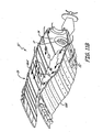
- FIG. 8 generically illustrates a fuel mal-distribution pattern in combustion chamber 19 in accordance with the present invention.
- combustion chamber 19 includes chamber sections 38A - 38F.
- chamber sections 38A - 38F For purposes of example, it is assumed that all six chamber sections are nearly identical, and that each section contains three swirl stabilized flames corresponding to the three fuel nozzles within each section.
- each of the chamber sections 38A - 38F are spatially connected and allow the passage of acoustic waves throughout combustion chamber 19.
- the thermoacoustic instabilities arise on account of the skew-symmetry in the heat release feedback, as described in reference to FIG. 4.
- the skew-symmetry is a direct result of the local asymmetry of the swirlers located within combustion chamber 19.
- Stability augmentation of the thermoacoustic instabilities within combustion chamber 19 may be achieved by the circumferential mal-distribution of fuel flow to each of chamber sections 38A - 38F.
- stability of the spinning waves within combustion chamber 19 may be achieved by scheduling fuel flow to each chamber section as a function of total fuel flow.
- a 2 nd harmonic pattern is utilized as described previously. This 2 nd harmonic pattern is approximated by the six section patterns shown in FIG. 8. As shown in FIG. 8, chamber sections 38A, 38C, and 38F receive more than the mean section fuel flow, whereas chamber sections 38B, 38D, and 38E receive correspondingly less.
- This fuel distribution pattern produces a non-uniform mean temperature distribution, which effectively produces a non-uniform wave speed within combustion chamber 19 based upon the relationship between temperature and wave speed discussed above.
- the magnitude of the temperature mal-distribution will determine its effectiveness in reducing thermoacoustic instabilities, as will be illustrated in the following figure.
- FIG. 9 is a graph illustrating effectiveness in reducing thermoacoustic instabilities as a function of the magnitude of the temperature mal-distribution.
- the greater the number on the "Amplitude” axis the greater the level of pressure oscillations of the +1 and -1 spinning wave modes, which results in a combustion system that is noisier and more unstable.
- the greater the number on the "% Temperature Mistuning” axis the greater the difference between the various "hot” and “cold” chamber sections.
- the "optimal" amount of fuel mal-distribution is about 10%.
- the preceding example is only one such example of controlling thermoacoustic instabilities according to the present invention, and is presented for purposes of explanation and not for limitation. Therefore, the "optimal" amount of fuel mal-distribution may be greater than or less than 10% depending upon the average fuel to air ratio in the combustion chamber.
- a first alternative to utilizing a flow divider valve is to design fuel nozzles 17 with different flow capacities.
- each of fuel zones 36A - 36F may be designated a "richer” fuel zone or a "leaner” fuel zone.
- the richer fuel zones would receive more fuel than the leaner fuel zones.
- the corresponding "richer” combustion chamber sections would be hotter, while the “leaner” combustion chamber sections would be cooler, thus creating a non-uniform temperature distribution within the combustion chamber.
- One way to create a "richer” fuel zone is to enlarge the apertures in the fuel nozzles to increase the amount of fuel the nozzle will discharge at a particular flow rate.
- each fuel nozzle may be designed with first and second fuel circuits for providing fuel to the nozzle. Below a predetermined fuel flow rate, only the first fuel circuits would provide fuel to their respective nozzles, creating a non-uniform fuel distribution (and thus, a non-uniform temperature distribution) within the combustion chamber. However, above the predetermined flow rate, both the first and second fuel circuits would provide fuel to their respective nozzles, creating a flow of fuel through each nozzle that is substantially equivalent. As a result, there would be a substantially uniform temperature distribution within the combustor.
- a second alternative to a flow divider valve is to utilize individual valves within each fuel nozzle 17 or fuel zones 36A - 36F.
- Each valve may be designed to change from a "closed" position (where no flow reaches the nozzles) to an "open” position (where all or part of the stream of fuel reaches the nozzles) at a predetermined fuel flow rate, thus providing variable temperature non-uniformity within the combustion chamber.
- a third alternative to a flow divider valve is to utilize fuel nozzles 17 having "fixed orifices.”
- nozzles having fixed orifices would provide a fixed non-uniformity between the fuel zones at all fuel flow rates.
- fixed orifice nozzles create a non-uniform temperature distribution over approximately the entire range of engine operating conditions unless a device capable of creating variable flow with fixed orifice nozzles is incorporated into the system.
- the temperature distribution may alternatively be controlled by controlling the amount of air distributed to the combustion chamber.
- the temperature of a combustion chamber section depends upon the fuel to air (f/a) ratio in its associated fuel zone.
- chamber sections associated with "richer” fuel zones are generally hotter than chamber sections associated with "leaner” fuel zones.
- a “richer” fuel zone may be created by distributing a fixed amount of air and increasing fuel flow to the zone, distributing a fixed amount of fuel and decreasing air flow to the zone, or increasing the fuel distributed to the fuel zone while decreasing the air flow.
- a "leaner" fuel zone may be created by distributing a fixed amount of air and decreasing fuel flow to the zone, distributing a fixed amount of fuel and increasing air flow to the zone, or decreasing fuel distributed to the fuel zone while increasing the air flow.
- a non-uniform temperature distribution may be created in a combustion chamber by varying fuel flow, air flow, or both.
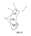
- FIG. 10 is a diagram illustrating a cut-out section of combustor 10 shown and described above in reference to FIG. 1.
- fuel nozzle 17 includes inner air swirler 70, fuel injector portion 72, and outer air swirler 74.
- Inner and outer air swirlers 70 and 74 are designed to provide combustion air to chamber sections 38A - 38F and meter the fuel to air ratio in the primary combustion zone at the front of combustion chamber 19.
- inner air swirler 70 is a cylindrical passage having a plurality of vane members configured to provide a "swirling air” source on the inside of fuel injector portion 72
- outer air swirler 74 is an annular-shaped passage having a plurality of vane members configured to provide a "swirling air” source on the outside of fuel injector portion 72.
- the swirling air distributed through inner and outer air swirlers 70 and 74 creates a shear force on the fuel, which is injected through annular-shaped fuel injector portion 72 between inner and outer air swirlers 70 and 74.
- Inner and outer air swirlers 70 and 74 not only provide a source of "combustion air" within combustion chamber 19, but they also act to break up the fuel injected through fuel portion 72 into droplets to enhance the combustion process. It is important to note that nozzle 17 is shown merely for purposes of example and not for limitation, and that other types of nozzles and air swirlers are also contemplated.
- Various nozzles 17 attached to fuel manifold assembly 16 may be designed such that, at the same pressure drop, their inner and outer air swirlers 70 and 74 provide different air flow rates into combustion chamber 19.
- each set of nozzles 17 in fuel zones 36A - 36F are designed to provide different air flow rates to create a non-uniform air flow distribution within combustion chamber 19.
- a non-uniform air flow distribution affects the temperature distribution within combustion chamber 19 in the same manner as a non-uniform fuel flow distribution.
- FIG. 11A is a cross-sectional view of combustor 10', which is similar to combustor 10 illustrated in FIG. 2 except that outer chamber section 18A' and inner chamber section 18B' each have a greater number of holes 22'.
- FIG. 11B is a cross-sectional view of combustor 10", which is similar to combustor. 10 illustrated in FIG. 2 except that outer chamber section 18A" and inner chamber section 18B" each have a fewer number of holes 22". Fewer air holes 22" results in an overall decrease in combustion air flow into combustion chamber 19, which leads to an increase in local chamber temperature.
- the present invention is a method for shaping mean combustor temperature in order to increase dynamic stability within the combustor.
- the method adaptively re-distributes the amount of fuel or air circumferentially within the combustor in an optimal pattern to cause beneficial energy exchange between various acoustic modes.
- the specific, optimal pattern will depend upon the shape of the thermoacoustic wave modes the method is attempting to control.
- the methodology of the present invention offers a means whereby more stable modes may be used to augment the damping of their less stable counterparts.
- the method may be configured to ensure that the fuel or air re-distribution is operational only when required as well as only to the extent necessary.
- the method exploits the modal structure of the combustion instabilities and thus enjoys several benefits including, but not limited to: (1) It is applicable to general combustion schemes including both swirl and bluff-body schemes; (2) The method does not require physics-based dynamic models for unsteady heat release response; (3) The approach is robust enough to handle many un-modeled physical effects, such as changes in frequency, as long as the modal structure of the thermoacoustic instability is approximately preserved; (4) The quantitative amount of mistuning necessary for stabilization of the thermoacoustic instabilities depends only upon the mean flow effects such as combustion chamber temperature; and (5) The method may be configured to operate only over a small portion of engine operating conditions where the thermoacoustic instability is present so that turbine durability and engine thrust are not compromised at most of the engine operating conditions.
Abstract
Description
- The present invention relates generally to gas turbine engines. More particularly, the present invention relates to a method for controlling thermoacoustic instabilities in a combustor.
- Thermoacoustic instabilities arise in gas turbine and aero-engines when acoustic modes couple with unsteady heat released due to combustion in a positive feedback loop. These instabilities can lead to large pressure oscillations inside the combustor cavity, thereby affecting its stable operation and potentially causing structural damage to the combustor components. Two particular examples of thermoacoustic instabilities in annular combustors are the "screech" instability in the afterburner and the "howl" instability in the primary combustion chamber.
- Prior art approaches for control of thermoacoustic instabilities typically utilized passive liners or tuned resonators configured to damp the acoustic mode. However, these solutions suffer from several disadvantages. In particular, they introduce additional weight and may be expensive to implement. In addition, resonators are effective only over a limited range of frequencies and become ineffective if the frequency of the instability changes because of, for example, changes in operating conditions. These passive devices have to be cooled, which may detrimentally affect the efficiency of the engine. Finally, effective tuned resonator design requires a prior knowledge of the frequency of instability.
- Active combustion control has also been considered as an approach for control of thermoacoustic instabilities. Active approaches usually require an accurate mathematical model of the thermoacoustic dynamics for control design. However, on account of complex combustion physics, the exact physical mechanism underlying the initiation and sustenance of instabilities such as screech typically is not understood. Furthermore, there are implementation issues such as lack of suitable bandwidth fuel valves that are needed for active control.
- The thermoacoustic instabilities typically appear only during a small portion of an aero-engine's flight envelope or operating conditions in the case of land-based combustors. Thus, passive dampers and active control systems are useful to help control thermoacoustic oscillations only over a small portion of operating conditions and have no useful function at nominal operating conditions. Furthermore, they negatively affect weight and performance of the engine at the operating conditions where the instability is not present.
- The present invention in one aspect is a method for controlling a temperature distribution within a combustor having a plurality of chamber sections comprising controlling a fuel-to-air ratio in the chamber sections. At least two chamber sections have different fuel-to-air ratios to create a non-uniform temperature distribution within the combustor to reduce thermoacoustic instabilities.
-
- FIG. 1 is a diagram illustrating a combustor of an aircraft engine.
- FIG. 2 is a cross-sectional view of a portion of the combustor.
- FIG. 3 is a diagram illustrating a fuel manifold.
- FIG. 4 is a block diagram illustrating how combustor acoustics affect a combustion process.
- FIG. 5 illustrates how skew-symmetric heat release feedback affects an acoustic mode.
- FIG. 6A illustrates the impact of an adaptive spatial fuel distribution method on skew-symmetric heat release feedback.
- FIG. 6B illustrates the effect of fuel mistuning beyond an optimal amount.
- FIG. 7 is a block diagram of a thermoacoustic model illustrating the feedback connections produced by non-uniformities in fuel distribution within a combustion chamber.
- FIG. 8 illustrates one embodiment of a fuel mal-distribution pattern in the combustion chamber.
- FIG. 9 is a graph illustrating effectiveness in reducing thermoacoustic instabilities as a function of the magnitude of temperature mal-distribution.
- FIG. 10 is a diagram illustrating an enlarged view of a section of the combustor illustrated in FIG. 1.
- FIG. 11A is a cross-sectional view of a first alternative combustor.
- FIG. 11B is a cross-sectional view of a second alternative combustor.
- FIG. 1 is a diagram illustrating an end view of an
annular combustor 10 of an aircraft engine havingbulkhead section 14. Attached tobulkhead section 14 isfuel manifold assembly 16, which includes a plurality of fuel nozzles 17 (as well as additional components not visible in FIG. 1). It should be noted that anannular combustor 10 is described for purposes of example and not for limitation, and that other types of combustors, such as cylindrical combustors, are also within the intended scope of the present invention. - Combustor 10 is configured to burn a mixture of fuel and air to produce combustion gases. These combustion gases are then delivered to a turbine located downstream of
combustor 10 at a temperature which will not exceed an allowable limit at the turbine inlet. Combustor 10, within a limited space, must add sufficient heat and energy to the gases passing through the engine to accelerate their mass enough to produce the desired power for the turbine and thrust for the engine. In addition to such things as high combustion efficiency and minimum pressure loss, another important criterion in burner and combustion chamber design is the ability to prevent or limit thermoacoustic instabilities within the combustor. - FIG. 2 is a cross-sectional view of
combustor 10, which further includesouter chamber section 18A andinner chamber section 18B. As shown in FIG. 2, when assembled,outer chamber section 18A andinner chamber section 18B create anannular combustion chamber 19, which includes apocket 20 where the combustion takes place.Outer chamber section 18A andinner chamber section 18B consist of continuous, circular shrouds configured to be positioned around the outside of a compressor drive shaft housing of the aircraft engine. A plurality ofholes 22 in outer andinner chamber sections combustion chamber 19, thereby keeping the burner flame away from outer andinner chamber sections - FIG. 3 is a diagram illustrating
fuel manifold assembly 16, which includesfuel nozzles 17,flow divider valve 30, and a plurality offuel lines 32. As shown in FIG. 3,fuel nozzles 17 are separated into groups and formfirst fuel zone 36A,second fuel zone 36B,third fuel zone 36C,fourth fuel zone 36D,fifth fuel zone 36E, andsixth fuel zone 36F.Fuel zones 36A - 36F are configured to control combustion within and temperature ofcorresponding chamber sections 38A - 38F ofcombustion chamber 19, which is represented by the doughnut-shaped region in the middle offuel manifold assembly 16. It should be understood that the doughnut-shaped region is a generic representation of the combustion chamber sections that correspond with the fuel zones, and is shown merely for purposes of explanation. - It is important to note that although the embodiment in FIG. 3 depicts
fuel manifold assembly 16 having six fuel zones, fuel manifolds having any number of fuel zones are possible. Furthermore, althoughfuel zones 36A - 36F are shown as having threefuel nozzles 17 per zone, fuel zones having any number offuel nozzles 17 are contemplated. - In one embodiment of a
combustor 10,flow divider valve 30 is configured to divide a single stream of fuel from a fuel source (not shown) into a plurality of fuel streams equal to the number of fuel zones, which equals six in the embodiment shown. Each offuel zones 36A - 36F is fed by one offuel lines 32, where a manifold dedicated to each fuel zone further apportions the fuel flow between eachfuel nozzle 17 in the fuel zone. In this embodiment,flow divider 30 may be configured to provide a desired combustor temperature distribution by controlling the amount of fuel distributed to each fuel zone at any given point in time. By controlling the amount of fuel distributed to each offuel zones 36A - 36F, and thus the temperature withincorresponding chamber sections 38A - 38F,flow divider valve 30 may help alleviate, among other things, thermoacoustic instabilities caused by the interaction between the acoustics ofcombustion chamber 19 and the combustion process itself. - The term "thermoacoustic instability" may refer to a wide range of oscillatory phenomena observable in combustion systems. Thermoacoustic instabilities in gas-turbine combustion chambers typically arise due to the fact that the combustion process leads to a localized, unsteady heat release with high energy. These oscillatory phenomena in combustion chambers result from the coupling of the unsteady heat release resulting from the combustion process with acoustic waves in the combustion chamber, which create pressure fluctuations with large amplitudes at various frequencies within the chamber. The instability frequencies are generally associated with the geometry of the combustion chamber and may be influenced by interactions between the combustion chamber and the flow field.
- Thermoacoustic instability is commonly referred to as "tonal noise." Not only is tonal noise objectionable to those individuals in and around an aircraft, but vibrations resulting from the tonal noise may also cause damage to portions of the aircraft, including engine components. Thus, suppressing thermoacoustic instabilities in a system is desirable not only to decrease the resulting audible annoyances, but also to increase system performance and improve engine life. The present invention provides a method for controlling thermoacoustic instabilities in a combustor by controlling the temperature field, and thus the speed of sound, within the combustor.
- FIG. 4 is a block diagram of a
thermoacoustic model 50 illustrating how combustor acoustics affect the combustion process. Thermoacoustic instabilities in annular combustors may be modeled as a feedback interconnection of a circumferentially distributed one-dimensional wave equation with feedback on account of such things as heat release, passive liners, and flow effects. The combustion is realized by circumferentially distributed elements, such as flameholders in bluff-body stabilized augmentors and swirlers in swirl stabilized combustion chambers. For purposes of explanation, a model for the heat release feedback is not assumed. Furthermore, for simplicity, it is assumed that the individual flameholders or swirlers are identical. However, the method of the present invention is not limited to identical flameholders or swirlers. - In the absence of any feedback, the nth circumferential mode (which may be denoted by nT) corresponds to two pairs of complex eigenvalues. The corresponding eigenvectors have the physical interpretation of the two counter-rotating waves, one rotating in the clockwise direction, and the other rotating in the counterclockwise direction. Similarly, the nT modes also have clockwise and counterclockwise directions of rotation. For purposes of example, it is assumed that a +1 tangential acoustic wave mode (a 1T mode) and a -1 tangential acoustic wave mode (also a 1T mode) represent the counter-rotating waves within
combustion chamber 19 throughout the remainder of this disclosure. - In reference to
thermoacoustic model 50 of FIG. 4, the combustion process creates flow disturbances and turbulence, as indicated byblock 52. The flow disturbances created by the combustion process interact with the system acoustics inherent incombustion chamber 19, which is shown by the arrow pointing fromblock 52 to block 54. As illustrated in FIG. 4, afeedback loop 56 connectsblock 54 andblock 58 in a continuous, closed loop, which represents system heat release continuously interacting with the system acoustics. The effect of the heat release feedback is to destabilize one or both of the waveform directions by causing their respective eigenvalues to become more unstable. - In general, any heat release feedback may be decomposed as a sum of symmetric and skew-symmetric feedback. As used here, a combustion element is defined as the combustion occurring behind a single flameholder or a single swirl nozzle. Conceptually, the symmetric feedback corresponds to combustion dynamics that have reflection symmetry while the skew-symmetry is a result of local asymmetry in combustion. The symmetric feedback acts on counter-rotating modes similarly, while skew-symmetric feedback stabilizes one rotating mode while destabilizing the counter-rotating mode. The present invention is particularly useful for controlling thermoacoustic instabilities arising from skew-symmertic feedback.
- FIG. 5 illustrates the impact of skew-symmetric heat release feedback on the nT modal eigenvalues of the acoustics. In particular, the eigenvalue corresponding to the +1 tangential acoustic wave mode is designated as E1 in FIG. 5, while the eigenvalue corresponding to the -1 tangential acoustic wave mode is designated as E2. As shown in FIG. 5, the skew-symmetric feedback splits eigenvalues E1 and E2, causing one rotating mode to gain damping (i.e., become more stable) while causing the other rotating mode to lose the same amount of damping (i.e., become less stable).
- Thermoacoustic instability occurs when the eigenvalue corresponding to the lightly damped direction (less stable wave mode) crosses the imaginary axis into the unstable region in FIG. 5. Even if the eigenvalue does not cross the imaginary axis into the unstable region, presence of a significant amount of turbulent noise together with a lightly damped eigenvalue causes large pressure oscillations. In either case, the resulting spatial waveform corresponds to a wave rotating in the direction consistent with that of the eigenvector of the lightly damped eigenvalue.
- The detrimental effect of the skew-symmetric feedback may be reversed using spatial mistuning of the wave (sound) speed by varying the spatial temperature distribution along the azimuthal direction of
combustion chamber 19. For nT-mode suppression, the optimal beneficial energy exchange between clockwise and counterclockwise wave modes results from a temperature distribution pattern withincombustion chamber 19 that has a 2nT-mode shape. In particular, the beneficial energy exchange between clockwise and counterclockwise nT modes is proportional to the 2nT-harmonic component of the mistuning pattern. Thus, in the example described herein where a 1T mode and a -1T mode represent the counter-rotating waves withincombustion chamber 19, a temperature distribution pattern that has a 2T-mode shape could be used to reverse the effect of the skew-symmetric feedback. Similarly, if a 2T mode and a -2T mode represented the counter-rotating waves withincombustion chamber 19, a temperature distribution pattern that has a 4T-mode shape could be used. Thus, any temperature distribution pattern that has approximately a 2nT-mode shape is within the intended scope of the present invention. - FIG. 6A illustrates the impact of the method of the present invention on the skew-symmetric heat release feedback. As shown in FIG. 6A, by varying the spatial fuel distribution within
fuel zones 36A - 36F, and thus the temperature within correspondingcombustion chamber sections 38A - 38F, variations in sound speed due to the non-uniform temperature distribution cause the eigenvalues to move close to one another, as illustrated by the directions of the arrows in FIG. 6A. Thus, the adaptive spatial fuel distribution withincombustion chamber 19 has resulted in an exchange of damping between the two counter-rotating wave modes. - The role of the temperature pattern can also be understood as mistuning of the two nT-rotating directions by introducing spatial variations in sound speed. Localized increase (or decrease) in the fuel delivery along the circumference of a combustion chamber, such as
combustion chamber 19, leads to increase (or decrease) in localized temperature that increases (or decreases) the localized sound wave speed. As a general rule of physics, the speed of sound within a combustor is proportional to the square root of the temperature within the combustor. Furthermore, temperature is a function of the fuel to air ratio associated with the combustor. Finally, since it may be presumed that the air is regularly distributed, the fuel to air ratio is a function of local fuel flow. Thus, by changing the distribution of fuel flow to cause more fuel to flow to certain chamber sections and less fuel to others, the speed of sound inchamber sections 38A- 38F may be controlled. - For a given skew-symmetric feedback (i.e., the "split" of eigenvalues illustrated in FIG. 5), there is an optimal amount of fuel variation that reverses the detrimental effect of the skew-symmetric feedback. This optimal amount corresponds to an eigenvalue diagram similar to FIG. 6A where the two 1T eigenvalues are relatively close to one another. Decreasing the amount of mistuning from the optimal amount causes one of the directions to become lightly damped at the expense of the other. On the other hand, increasing the mistuning beyond the optimal amount causes the two counter-rotating waves to shift in frequency without any additional damping benefit. This phenomenon is illustrated in FIG. 6B. As shown in FIG. 6B, if
fuel zones 36A - 36F are "mistuned" beyond the optimal amount of fuel variation, the optimal amount of "damping exchange" between the modes is exceeded, and the only effect of the additional fuel variation is to cause a further split in frequency between eigenvalues E1 and E2 as indicated by the directions of the arrows in FIG. 6B. As a result, beyond the optimal amount of fuel mistuning, no further beneficial energy exchange (damping) occurs between the counter-rotating wave modes. - While spatially non-uniform fueling leads to suppression of thermoacoustic instabilities, non-uniform fueling also leads to non-uniform circumferential temperature distribution that can detrimentally affect engine durability. In order to keep temperature within
combustion chamber 19 as uniform as possible over the largest portion of the flight envelope or flight operating conditions, the method of the present invention should be used to adjust the fuel distribution profile as engine operating conditions change. The fuel distribution method may be carried out by using, for example, a low bandwidth closed-loop fuel re-distribution scheme or an open-loop fuel re-distribution scheme based on external parameters such as the flight conditions or other engine variables. The necessary speed of the fuel re-distribution will be dependent upon and will be a function of the timescale of changes in the engine operating conditions. - The adaptive scheduling varies the fuel re-distribution depending on the desired amount of damping augmentation at a particular operating condition. For example, during engine operating conditions where thermoacoustic instabilities do not occur, no damping augmentation is needed and the fuel profile within
combustion chamber 19 should be substantially uniform. However, as the desired amount of damping changes based upon changes in operating conditions, the adaptive fuel re-distribution method may be configured to provide the necessary amount of damping to take into account the changed conditions. Thus, because the fuel re-distribution is operational only when required and only by the necessary amount, the engine will have increased durability. - FIG. 7 is a modified version of
thermoacoustic model 50 shown and described above in FIG. 4 illustrating the feedback connections produced by wave speed mistuning, which results from spatial non-uniformities of fuel distribution withincombustion chamber 19. Similar tothermoacoustic model 50, the combustion process creates flow disturbances and turbulence, which interact with the acoustics ofcombustion chamber 19 and results in a lightly damped acoustic mode (Mode 1) and a highly damped acoustic mode (Mode 2). Heat release feedback again interacts with the two acoustic modes, resulting in skew-symmetric feedback as discussed above. However, applying the fuel distribution method of the present invention, a sound speed mistuning pattern caused by a non-uniform temperature distribution withincombustion chamber 19 creates a beneficial energy exchange feedback loop between the lightly damped and highly damped acoustic modes. As discussed previously, for nT-mode suppression, the optimal beneficial energy exchange between clockwise and counterclockwise wave modes results from a spatial fuel distribution pattern that has a 2nT-mode shape. - FIG. 8 generically illustrates a fuel mal-distribution pattern in
combustion chamber 19 in accordance with the present invention. As discussed above in reference to FIG. 3,combustion chamber 19 includeschamber sections 38A - 38F. For purposes of example, it is assumed that all six chamber sections are nearly identical, and that each section contains three swirl stabilized flames corresponding to the three fuel nozzles within each section. Furthermore, it is assumed that each of thechamber sections 38A - 38F are spatially connected and allow the passage of acoustic waves throughoutcombustion chamber 19. As discussed previously, the thermoacoustic instabilities arise on account of the skew-symmetry in the heat release feedback, as described in reference to FIG. 4. In particular, the skew-symmetry is a direct result of the local asymmetry of the swirlers located withincombustion chamber 19. - Stability augmentation of the thermoacoustic instabilities within
combustion chamber 19 may be achieved by the circumferential mal-distribution of fuel flow to each ofchamber sections 38A - 38F. In particular, stability of the spinning waves withincombustion chamber 19 may be achieved by scheduling fuel flow to each chamber section as a function of total fuel flow. In this example, in order to exchange energy between the +1 tangential spinning wave mode and the -1 tangential spinning wave mode, a 2nd harmonic pattern is utilized as described previously. This 2nd harmonic pattern is approximated by the six section patterns shown in FIG. 8. As shown in FIG. 8,chamber sections chamber sections combustion chamber 19 based upon the relationship between temperature and wave speed discussed above. The magnitude of the temperature mal-distribution will determine its effectiveness in reducing thermoacoustic instabilities, as will be illustrated in the following figure. - FIG. 9 is a graph illustrating effectiveness in reducing thermoacoustic instabilities as a function of the magnitude of the temperature mal-distribution. In general, the greater the number on the "Amplitude" axis the greater the level of pressure oscillations of the +1 and -1 spinning wave modes, which results in a combustion system that is noisier and more unstable. Furthermore, the greater the number on the "% Temperature Mistuning" axis the greater the difference between the various "hot" and "cold" chamber sections.
- As shown in FIG. 9, when there is a uniform temperature distribution within combustion chamber 19 (0% temperature mistuning), the system reaches its highest level of noise and instability. As the temperature distribution within
combustion chamber 19 becomes non-uniform, amplitude first rapidly decreases, and then begins to level out at about 10% temperature mistuning. In fact, when dealing with a 2nT-harmonic pattern such as the example used throughout this disclosure, any circumferential fuel re-distribution pattern greater than about 4% of the mean circumferential fuel flow rate will have noticeable beneficial effect on stability of the spinning wave modes. - As shown in FIG. 9, any temperature mistuning up to about 10% will result in an effect on eigenvalues similar to that described above in reference to FIG. 6A. However, any temperature mistuning over about 10% will result in an effect similar to that described above in reference to FIG. 6B. Therefore, in this particular example involving a combustion chamber having six separately-fueled chamber sections, the "optimal" amount of fuel mal-distribution is about 10%. However, it should be understood that the preceding example is only one such example of controlling thermoacoustic instabilities according to the present invention, and is presented for purposes of explanation and not for limitation. Therefore, the "optimal" amount of fuel mal-distribution may be greater than or less than 10% depending upon the average fuel to air ratio in the combustion chamber.
- Although the method of the present invention has been described above as utilizing a flow divider valve to distribute controlled amounts of fuel to
combustor 10, embodiments that do not utilize a flow divider valve are also contemplated and within the intended scope of the present invention. - A first alternative to utilizing a flow divider valve is to design
fuel nozzles 17 with different flow capacities. In particular, each offuel zones 36A - 36F may be designated a "richer" fuel zone or a "leaner" fuel zone. At a particular fuel flow rate, the richer fuel zones would receive more fuel than the leaner fuel zones. As a result, the corresponding "richer" combustion chamber sections would be hotter, while the "leaner" combustion chamber sections would be cooler, thus creating a non-uniform temperature distribution within the combustion chamber. One way to create a "richer" fuel zone is to enlarge the apertures in the fuel nozzles to increase the amount of fuel the nozzle will discharge at a particular flow rate. Similarly, one way to create a "leaner" fuel zone is to decrease the size of the apertures in the fuel nozzles to decrease the amount of fuel that the nozzle will discharge. Furthermore, these fuel nozzles could be designed to provide variable fuel uniformity as a function of fuel flow rate if a staged fuel system is used. For example, each fuel nozzle may be designed with first and second fuel circuits for providing fuel to the nozzle. Below a predetermined fuel flow rate, only the first fuel circuits would provide fuel to their respective nozzles, creating a non-uniform fuel distribution (and thus, a non-uniform temperature distribution) within the combustion chamber. However, above the predetermined flow rate, both the first and second fuel circuits would provide fuel to their respective nozzles, creating a flow of fuel through each nozzle that is substantially equivalent. As a result, there would be a substantially uniform temperature distribution within the combustor. - A second alternative to a flow divider valve is to utilize individual valves within each
fuel nozzle 17 orfuel zones 36A - 36F. Each valve may be designed to change from a "closed" position (where no flow reaches the nozzles) to an "open" position (where all or part of the stream of fuel reaches the nozzles) at a predetermined fuel flow rate, thus providing variable temperature non-uniformity within the combustion chamber. - A third alternative to a flow divider valve is to utilize
fuel nozzles 17 having "fixed orifices." In general, nozzles having fixed orifices would provide a fixed non-uniformity between the fuel zones at all fuel flow rates. Thus, unlikeflow divider valve 30 discussed above, fixed orifice nozzles create a non-uniform temperature distribution over approximately the entire range of engine operating conditions unless a device capable of creating variable flow with fixed orifice nozzles is incorporated into the system. - Although the discussion above focused on controlling a temperature distribution within a combustion chamber by controlling the amount of fuel distributed to a plurality of fuel nozzles (or fuel zones), the temperature distribution may alternatively be controlled by controlling the amount of air distributed to the combustion chamber. In particular, the temperature of a combustion chamber section depends upon the fuel to air (f/a) ratio in its associated fuel zone. As discussed above, chamber sections associated with "richer" fuel zones are generally hotter than chamber sections associated with "leaner" fuel zones. A "richer" fuel zone may be created by distributing a fixed amount of air and increasing fuel flow to the zone, distributing a fixed amount of fuel and decreasing air flow to the zone, or increasing the fuel distributed to the fuel zone while decreasing the air flow. Similarly, a "leaner" fuel zone may be created by distributing a fixed amount of air and decreasing fuel flow to the zone, distributing a fixed amount of fuel and increasing air flow to the zone, or decreasing fuel distributed to the fuel zone while increasing the air flow. As can be seen from these examples, a non-uniform temperature distribution may be created in a combustion chamber by varying fuel flow, air flow, or both.
- One method for varying the amount of combustion air flowing into
combustion chamber 19 involves designing fuel nozzle air swirlers with different flow capacities. FIG. 10 is a diagram illustrating a cut-out section ofcombustor 10 shown and described above in reference to FIG. 1. As shown in FIG. 10,fuel nozzle 17 includesinner air swirler 70, fuel injector portion 72, and outer air swirler 74. Inner and outer air swirlers 70 and 74 are designed to provide combustion air tochamber sections 38A - 38F and meter the fuel to air ratio in the primary combustion zone at the front ofcombustion chamber 19. In one embodiment,inner air swirler 70 is a cylindrical passage having a plurality of vane members configured to provide a "swirling air" source on the inside of fuel injector portion 72, while outer air swirler 74 is an annular-shaped passage having a plurality of vane members configured to provide a "swirling air" source on the outside of fuel injector portion 72. The swirling air distributed through inner and outer air swirlers 70 and 74 creates a shear force on the fuel, which is injected through annular-shaped fuel injector portion 72 between inner and outer air swirlers 70 and 74. Inner and outer air swirlers 70 and 74 not only provide a source of "combustion air" withincombustion chamber 19, but they also act to break up the fuel injected through fuel portion 72 into droplets to enhance the combustion process. It is important to note thatnozzle 17 is shown merely for purposes of example and not for limitation, and that other types of nozzles and air swirlers are also contemplated. -
Various nozzles 17 attached to fuelmanifold assembly 16 may be designed such that, at the same pressure drop, their inner and outer air swirlers 70 and 74 provide different air flow rates intocombustion chamber 19. In one embodiment, each set ofnozzles 17 infuel zones 36A - 36F are designed to provide different air flow rates to create a non-uniform air flow distribution withincombustion chamber 19. As discussed above, a non-uniform air flow distribution affects the temperature distribution withincombustion chamber 19 in the same manner as a non-uniform fuel flow distribution. Thus, it is possible to achieve a non-uniform temperature distribution within combustion chamber 19 (and thus, control thermoacoustic instabilities) by varying the amount of combustion air distributed intocombustion chamber 19. - Another method for varying the amount of combustion air flowing into
combustion chamber 19 involves varying the "quench" air flow intocombustion chamber 19. In this disclosure, "quench" air is the combustion air flow distributed into a combustion chamber through the air holes in the outer and inner chamber sections. For example, some fuel zones may be designed with a greater number of air holes or holes with larger diameters to provide increased air flow into the combustion chamber sections that are preferably cooler. This type of design is illustrated in FIG. 11A. In particular, FIG. 11A is a cross-sectional view of combustor 10', which is similar tocombustor 10 illustrated in FIG. 2 except thatouter chamber section 18A' andinner chamber section 18B' each have a greater number of holes 22'. A greater number of air holes 22' results in an overall increase in combustion air flow intocombustion chamber 19, which leads to a decrease in chamber temperature. Other fuel zones may be designed with fewer holes or holes with smaller diameters to provide decreased air flow into combustion chamber sections that are preferably hotter. This type of design is illustrated in FIG. 11B. In particular, FIG. 11B is a cross-sectional view ofcombustor 10", which is similar to combustor. 10 illustrated in FIG. 2 except thatouter chamber section 18A" andinner chamber section 18B" each have a fewer number ofholes 22".Fewer air holes 22" results in an overall decrease in combustion air flow intocombustion chamber 19, which leads to an increase in local chamber temperature. - It should be understood that other methods for varying air flow into a combustion chamber to create a non-uniform temperature distribution that are consistent with the above disclosure are also contemplated. Furthermore, although the above methods for varying the amount of combustion air create "fixed" temperature non-uniformities, methods that allow the non-uniform temperature distribution to transform into a substantially uniform temperature distribution at certain operating conditions are also within the intended scope of the present invention.
- The present invention is a method for shaping mean combustor temperature in order to increase dynamic stability within the combustor. The method adaptively re-distributes the amount of fuel or air circumferentially within the combustor in an optimal pattern to cause beneficial energy exchange between various acoustic modes. The specific, optimal pattern will depend upon the shape of the thermoacoustic wave modes the method is attempting to control. In particular, the methodology of the present invention offers a means whereby more stable modes may be used to augment the damping of their less stable counterparts. Furthermore, the method may be configured to ensure that the fuel or air re-distribution is operational only when required as well as only to the extent necessary.
- The method exploits the modal structure of the combustion instabilities and thus enjoys several benefits including, but not limited to: (1) It is applicable to general combustion schemes including both swirl and bluff-body schemes; (2) The method does not require physics-based dynamic models for unsteady heat release response; (3) The approach is robust enough to handle many un-modeled physical effects, such as changes in frequency, as long as the modal structure of the thermoacoustic instability is approximately preserved; (4) The quantitative amount of mistuning necessary for stabilization of the thermoacoustic instabilities depends only upon the mean flow effects such as combustion chamber temperature; and (5) The method may be configured to operate only over a small portion of engine operating conditions where the thermoacoustic instability is present so that turbine durability and engine thrust are not compromised at most of the engine operating conditions.
- Although the present invention has been described with reference to preferred embodiments, workers skilled in the art will recognize that changes may be made in form and detail without departing from the scope of the invention.
Claims (33)
- A method for controlling a temperature distribution within a combustor (10) having a plurality of chamber sections (38A...38F) comprising:controlling a fuel-to-air ratio in the chamber sections (38A...38F), wherein at least two chamber sections have different fuel-to-air ratios to create a non-uniform temperature distribution within the combustor to reduce thermoacoustic instabilities.
- The method of claim 1, wherein the non-uniform temperature distribution is configured to reduce thermoacoustic instabilities by counteracting the effect of heat release feedback.
- The method of claim 1 or 2, wherein the non-uniform temperature distribution creates a non-uniform wave speed profile within the combustor (10).
- The method of claim 3, wherein the non-uniform wave speed profile causes an exchange of energy between a plurality of thermoacoustic wave modes.
- The method of claim 4, wherein one of the thermoacoustic wave modes is a highly damped wave mode, and wherein another one of the thermoacoustic wave modes is a lightly damped wave mode.
- The method of any preceding claim, wherein the fuel-to-air ratio is controlled by distributing controlled amounts of air to the chamber sections (38A...38F).
- The method of claim 6, wherein the combustor (10) includes a plurality of air swirlers (70, 74) configured to distribute the controlled amounts of air to the chamber sections.
- The method of claim 6 or 7, and further comprising adjusting the controlled amount of air distributed to each chamber section as a function of an engine operating condition.
- The method of claim 8, wherein the engine operating condition is engine speed.
- The method of any of claims 1 to 6, wherein the fuel-to-air ratio is controlled by distributing controlled amounts of fuel to the chamber sections.
- The method of claim 10, wherein the fuel is divided in a flow divider valve (30).
- The method of claim 11, and further comprising adjusting the controlled amount of fuel distributed to each chamber section (38A...38F) as a function of total fuel flow rate into the flow divider valve (30).
- The method of claim 12, wherein the non-uniform temperature distribution is transformed into a substantially uniform temperature distribution above a particular total fuel flow rate value.
- A method for controlling thermoacoustic instabilities in a combustor (10) comprising:creating a non-uniform temperature distribution within the combustor (10) by controlling a combustor condition.
- The method of claim 14, wherein the combustor condition is amount of fuel distributed to a plurality of chamber sections (38A...38F) within the combustor.
- The method of claim 14, wherein the combustor condition is amount of air flow distributed to a plurality of chamber sections (38A...38F) within the combustor (10).
- The method of claim 16, wherein controlled amounts of air are distributed to the chamber sections (38A...38F) to create a non-uniform temperature distribution within the combustor (10).
- The method of claim 17, wherein the combustor (10) includes a plurality of air swirlers (70, 74) configured to distribute the controlled amounts of air to the chamber sections (38A... 38F).
- The method of claim 17 or 18, and further comprising adjusting the controlled amount of air distributed to each chamber section (38A...38B) as a function of an engine operating condition.
- The method of claim 19, wherein the engine operating condition is engine speed.
- A method for controlling thermoacoustic instabilities in a combustor (10) comprising:dividing fuel from a fuel source in a flow divider valve (30); anddistributing controlled amounts of fuel from the flow divider valve (30) to a plurality of fuel zones (36A...36F) in a non-uniform pattern to reduce thermoacoustic instabilities.
- The method of claim 21, wherein the non-uniform pattern reduces thermoacoustic instabilities by counteracting the effect of heat release feedback.
- The method of claim 21 or 22, wherein the non-uniform fuel pattern results in a non-uniform temperature distribution within the combustor.
- The method of claim 21, 22 or 23, and further comprising adjusting the controlled amount of fuel distributed to each fuel zone (36A...36F) as a function of total fuel flow rate into the flow divider valve (30).
- The method of claim 24, wherein the non-uniform fuel pattern is transformed into a substantially uniform fuel pattern above a particular total fuel flow rate value.
- The method of any of claims 21 to 25, wherein the combustor (10) is an annular combustor.
- The method of claim 26, wherein.the annular combustor (10) is a swirl stabilized annular combustor.
- The method of any of claims 21 to 25, wherein the combustor (10) is a cylindrical combustor.
- A method for controlling a temperature distribution within a combustor (10) comprising:distributing controlled amounts of fuel to a plurality of fuel zones (36A...36F), wherein at least two fuel zones (36A...36F) receive different amounts amounts of fuel to create a non-uniform fuel profile within the combustor to reduce thermoacoustic instabilities.
- The method of claim 29, wherein the non-uniform fuel profile results in a non-uniform temperature distribution within the combustor (10).
- The method of claim 30, wherein the non-uniform temperature distribution creates a non-uniform wave speed profile within the combustor (10).
- The method of claim 31, wherein the non-uniform wave speed profile causes an exchange of energy between a plurality of thermoacoustic wave modes.
- The method of claim 32, wherein one of the thermoacoustic wave modes is a highly damped wave mode, and wherein another one of the thermoacoustic wave modes is a lightly damped wave mode.
Applications Claiming Priority (1)
| Application Number | Priority Date | Filing Date | Title |
|---|---|---|---|
| US11/527,225 US8037688B2 (en) | 2006-09-26 | 2006-09-26 | Method for control of thermoacoustic instabilities in a combustor |
Publications (3)
| Publication Number | Publication Date |
|---|---|
| EP1906093A2 true EP1906093A2 (en) | 2008-04-02 |
| EP1906093A3 EP1906093A3 (en) | 2011-06-29 |
| EP1906093B1 EP1906093B1 (en) | 2017-08-30 |
Family
ID=38791494
Family Applications (1)
| Application Number | Title | Priority Date | Filing Date |
|---|---|---|---|
| EP07253776.4A Active EP1906093B1 (en) | 2006-09-26 | 2007-09-24 | Method for control of thermoacoustic instabilities in a combustor |
Country Status (3)
| Country | Link |
|---|---|
| US (1) | US8037688B2 (en) |
| EP (1) | EP1906093B1 (en) |
| JP (1) | JP2008082330A (en) |
Cited By (2)
| Publication number | Priority date | Publication date | Assignee | Title |
|---|---|---|---|---|
| CN102933904A (en) * | 2010-06-17 | 2013-02-13 | 西门子公司 | Damping device for damping pressure oscillations within a combustion chamber of a turbine |
| EP2848865A1 (en) * | 2013-09-12 | 2015-03-18 | Alstom Technology Ltd | Thermoacoustic stabilization method |
Families Citing this family (35)
| Publication number | Priority date | Publication date | Assignee | Title |
|---|---|---|---|---|
| US8437941B2 (en) | 2009-05-08 | 2013-05-07 | Gas Turbine Efficiency Sweden Ab | Automated tuning of gas turbine combustion systems |
| US9267443B2 (en) | 2009-05-08 | 2016-02-23 | Gas Turbine Efficiency Sweden Ab | Automated tuning of gas turbine combustion systems |
| US9671797B2 (en) | 2009-05-08 | 2017-06-06 | Gas Turbine Efficiency Sweden Ab | Optimization of gas turbine combustion systems low load performance on simple cycle and heat recovery steam generator applications |
| US9354618B2 (en) | 2009-05-08 | 2016-05-31 | Gas Turbine Efficiency Sweden Ab | Automated tuning of multiple fuel gas turbine combustion systems |
| US10054313B2 (en) | 2010-07-08 | 2018-08-21 | Siemens Energy, Inc. | Air biasing system in a gas turbine combustor |
| US8745987B2 (en) * | 2010-10-28 | 2014-06-10 | General Electric Company | Late lean injection manifold |
| US9958162B2 (en) | 2011-01-24 | 2018-05-01 | United Technologies Corporation | Combustor assembly for a turbine engine |
| US8973368B2 (en) | 2011-01-26 | 2015-03-10 | United Technologies Corporation | Mixer assembly for a gas turbine engine |
| US8312724B2 (en) | 2011-01-26 | 2012-11-20 | United Technologies Corporation | Mixer assembly for a gas turbine engine having a pilot mixer with a corner flame stabilizing recirculation zone |
| US9920932B2 (en) | 2011-01-26 | 2018-03-20 | United Technologies Corporation | Mixer assembly for a gas turbine engine |
| US8875516B2 (en) | 2011-02-04 | 2014-11-04 | General Electric Company | Turbine combustor configured for high-frequency dynamics mitigation and related method |
| US9631560B2 (en) * | 2011-11-22 | 2017-04-25 | United Technologies Corporation | Fuel-air mixture distribution for gas turbine engine combustors |
| US10240533B2 (en) | 2011-11-22 | 2019-03-26 | United Technologies Corporation | Fuel distribution within a gas turbine engine combustor |
| US9243564B2 (en) * | 2012-09-04 | 2016-01-26 | General Electric Company | Systems and methods for removing impurities from heavy fuel oil |
| WO2014052221A1 (en) * | 2012-09-28 | 2014-04-03 | United Technologies Corporation | Fuel distribution within a gas turbine engine combustor |
| KR101503321B1 (en) * | 2013-09-17 | 2015-03-17 | 두산중공업 주식회사 | Apparatus for estimating resonance within combustion device |
| EP2853719A1 (en) * | 2013-09-25 | 2015-04-01 | Alstom Technology Ltd | Gas turbine with staged fuel injection |
| JP2015083779A (en) | 2013-10-25 | 2015-04-30 | 三菱日立パワーシステムズ株式会社 | Gas turbine combustor and gas turbine combustor control method |
| US9709278B2 (en) * | 2014-03-12 | 2017-07-18 | General Electric Company | System and method for control of combustion dynamics in combustion system |
| GB201408058D0 (en) * | 2014-05-07 | 2014-06-18 | Rolls Royce Plc | A fuel manifold and fuel injector arrangement for a combustion chamber |
| EP2975326B1 (en) | 2014-07-18 | 2019-09-18 | United Technologies Corporation | Combustor assembly for a turbine engine |
| EP3056819B1 (en) * | 2015-02-11 | 2020-04-01 | Ansaldo Energia Switzerland AG | Fuel injection device for a gas turbine |
| EP3104078A1 (en) * | 2015-06-12 | 2016-12-14 | IFTA Ingenieurbüro Für Thermoakustik GmbH | Thermoacoustic precursor method and apparatus |
| US11598527B2 (en) * | 2016-06-09 | 2023-03-07 | Raytheon Technologies Corporation | Reducing noise from a combustor of a gas turbine engine |
| US10724739B2 (en) | 2017-03-24 | 2020-07-28 | General Electric Company | Combustor acoustic damping structure |
| US10533502B2 (en) * | 2017-04-03 | 2020-01-14 | United Technologies Corporation | Combustor fuel manifold |
| US10415480B2 (en) | 2017-04-13 | 2019-09-17 | General Electric Company | Gas turbine engine fuel manifold damper and method of dynamics attenuation |
| JP2019020071A (en) * | 2017-07-19 | 2019-02-07 | 三菱重工業株式会社 | Combustor and gas turbine |
| US10760793B2 (en) * | 2017-07-21 | 2020-09-01 | General Electric Company | Jet in cross flow fuel nozzle for a gas turbine engine |
| US11149948B2 (en) * | 2017-08-21 | 2021-10-19 | General Electric Company | Fuel nozzle with angled main injection ports and radial main injection ports |
| US11181274B2 (en) | 2017-08-21 | 2021-11-23 | General Electric Company | Combustion system and method for attenuation of combustion dynamics in a gas turbine engine |
| US11561008B2 (en) * | 2017-08-23 | 2023-01-24 | General Electric Company | Fuel nozzle assembly for high fuel/air ratio and reduced combustion dynamics |
| US11156162B2 (en) | 2018-05-23 | 2021-10-26 | General Electric Company | Fluid manifold damper for gas turbine engine |
| US11506125B2 (en) | 2018-08-01 | 2022-11-22 | General Electric Company | Fluid manifold assembly for gas turbine engine |
| CN114151827B (en) * | 2022-02-08 | 2022-07-08 | 中国航发四川燃气涡轮研究院 | Flexible fuel manifold integrated with fuel nozzle |
Citations (6)
| Publication number | Priority date | Publication date | Assignee | Title |
|---|---|---|---|---|
| WO1998012478A1 (en) * | 1996-09-16 | 1998-03-26 | Siemens Aktiengesellschaft | Method and device for fuel combustion with air |
| EP1331448A2 (en) * | 2002-01-29 | 2003-07-30 | General Electric Company | Fuel control and tuning method for dry low NOx gas turbine engines |
| EP1555484A2 (en) * | 2004-01-19 | 2005-07-20 | ALSTOM Technology Ltd | Process to operate a gas turbine combustor |
| WO2006082210A1 (en) * | 2005-02-04 | 2006-08-10 | Enel Produzione S.P.A. | Thermoacoustic oscillation damping in gas turbine combustors with annular plenum |
| US20070039329A1 (en) * | 2005-08-22 | 2007-02-22 | Abreu Mario E | System and method for attenuating combustion oscillations in a gas turbine engine |
| US20090241548A1 (en) * | 2008-03-31 | 2009-10-01 | Allen Michael Danis | Gas turbine engine combustor circumferential acoustic reduction using flame temperature nonuniformities |
Family Cites Families (18)
| Publication number | Priority date | Publication date | Assignee | Title |
|---|---|---|---|---|
| US2731976A (en) | 1956-01-24 | Engine fuel system | ||
| US2536440A (en) | 1945-05-22 | 1951-01-02 | Hobson Ltd H M | Fuel distributing valve |
| US2664910A (en) | 1950-06-17 | 1954-01-05 | A V Roe Canada Ltd | Flow distributor valve |
| US2700394A (en) | 1951-01-06 | 1955-01-25 | A V Roe Canada Ltd | Flow distributor valve |
| US2832368A (en) | 1954-11-22 | 1958-04-29 | Collier Carbon & Chemical Co | Fluid distribution device |
| US2782739A (en) | 1955-04-22 | 1957-02-26 | Union Oil Co | Distribution of fluids |
| US4226365A (en) | 1979-06-27 | 1980-10-07 | United Technologies Corporation | Fuel distribution valve for a gas turbine engine |
| US5003771A (en) * | 1988-10-13 | 1991-04-02 | United Technologies Corporation | Fuel distribution valve for a combustion chamber |
| US5131426A (en) | 1991-05-06 | 1992-07-21 | Dana Corporation | Valving system for water flow to turbine engine emission system |
| FR2718793B1 (en) * | 1994-04-13 | 1996-05-24 | Snecma | Fuel injector fuel supply system. |
| US5491970A (en) * | 1994-06-10 | 1996-02-20 | General Electric Co. | Method for staging fuel in a turbine between diffusion and premixed operations |
| US5941074A (en) | 1995-11-14 | 1999-08-24 | Dana Corporation | Multi-port proportional fuel control valve for gas turbine engine |
| US5694967A (en) | 1995-11-14 | 1997-12-09 | Dana Corporation | Multi-port proportional flow control valve |
| US6092546A (en) | 1997-12-12 | 2000-07-25 | Alliedsignal Inc. | Fuel flow divider and pressurizing valve for gas turbine |
| US6311716B1 (en) | 2000-09-05 | 2001-11-06 | John Blue Company | Fluid flow divider |
| JP4683787B2 (en) * | 2001-03-09 | 2011-05-18 | 大阪瓦斯株式会社 | Burner device and gas turbine engine |
| US7546740B2 (en) * | 2004-05-11 | 2009-06-16 | United Technologies Corporation | Nozzle |
| JP4015656B2 (en) * | 2004-11-17 | 2007-11-28 | 三菱重工業株式会社 | Gas turbine combustor |
-
2006
- 2006-09-26 US US11/527,225 patent/US8037688B2/en active Active
-
2007
- 2007-09-14 JP JP2007238721A patent/JP2008082330A/en active Pending
- 2007-09-24 EP EP07253776.4A patent/EP1906093B1/en active Active
Patent Citations (6)
| Publication number | Priority date | Publication date | Assignee | Title |
|---|---|---|---|---|
| WO1998012478A1 (en) * | 1996-09-16 | 1998-03-26 | Siemens Aktiengesellschaft | Method and device for fuel combustion with air |
| EP1331448A2 (en) * | 2002-01-29 | 2003-07-30 | General Electric Company | Fuel control and tuning method for dry low NOx gas turbine engines |
| EP1555484A2 (en) * | 2004-01-19 | 2005-07-20 | ALSTOM Technology Ltd | Process to operate a gas turbine combustor |
| WO2006082210A1 (en) * | 2005-02-04 | 2006-08-10 | Enel Produzione S.P.A. | Thermoacoustic oscillation damping in gas turbine combustors with annular plenum |
| US20070039329A1 (en) * | 2005-08-22 | 2007-02-22 | Abreu Mario E | System and method for attenuating combustion oscillations in a gas turbine engine |
| US20090241548A1 (en) * | 2008-03-31 | 2009-10-01 | Allen Michael Danis | Gas turbine engine combustor circumferential acoustic reduction using flame temperature nonuniformities |
Cited By (2)
| Publication number | Priority date | Publication date | Assignee | Title |
|---|---|---|---|---|
| CN102933904A (en) * | 2010-06-17 | 2013-02-13 | 西门子公司 | Damping device for damping pressure oscillations within a combustion chamber of a turbine |
| EP2848865A1 (en) * | 2013-09-12 | 2015-03-18 | Alstom Technology Ltd | Thermoacoustic stabilization method |
Also Published As
| Publication number | Publication date |
|---|---|
| US8037688B2 (en) | 2011-10-18 |
| EP1906093A3 (en) | 2011-06-29 |
| JP2008082330A (en) | 2008-04-10 |
| EP1906093B1 (en) | 2017-08-30 |
| US20080072605A1 (en) | 2008-03-27 |
Similar Documents
| Publication | Publication Date | Title |
|---|---|---|
| EP1906093B1 (en) | Method for control of thermoacoustic instabilities in a combustor | |
| US7631500B2 (en) | Methods and apparatus to facilitate decreasing combustor acoustics | |
| US7578130B1 (en) | Methods and systems for combustion dynamics reduction | |
| CA2384336C (en) | A combustion chamber | |
| US7827797B2 (en) | Injection assembly for a combustor | |
| JP6514524B2 (en) | System and method for controlling combustion dynamics in a combustion system | |
| EP3767177B1 (en) | Combustor dome damper system | |
| JP4559616B2 (en) | Combustion chamber | |
| US8631656B2 (en) | Gas turbine engine combustor circumferential acoustic reduction using flame temperature nonuniformities | |
| US20070128564A1 (en) | Burner | |
| US20070039329A1 (en) | System and method for attenuating combustion oscillations in a gas turbine engine | |
| US20010018172A1 (en) | Combustors with improved dynamics | |
| US20110165527A1 (en) | Method and Apparatus of Combustor Dynamics Mitigation | |
| US9869473B2 (en) | Conical-flat heat shield for gas turbine engine combustor dome | |
| JP3192055B2 (en) | Gas turbine combustor | |
| EP3452756B1 (en) | High frequency acoustic damper for combustor liners and method of damping | |
| CN112066415B (en) | Combustion chamber, gas turbine and method for suppressing oscillatory combustion | |
| US20130305729A1 (en) | Turbomachine combustor and method for adjusting combustion dynamics in the same | |
| US20150330636A1 (en) | System and method for control of combustion dynamics in combustion system | |
| US20220275940A1 (en) | Gas Turbine Combuster | |
| JPH08303779A (en) | Gas turbine combustor | |
| EP3376110A1 (en) | Burner unit for a gas turbine electrical power plant, gas turbine electrical power plant comprising said burner unit and method for operating said gas turbine electrical power plant | |
| EP3406974A1 (en) | A mixer and a method for operating the same |
Legal Events
| Date | Code | Title | Description |
|---|---|---|---|
| PUAI | Public reference made under article 153(3) epc to a published international application that has entered the european phase |
Free format text: ORIGINAL CODE: 0009012 |
|
| AK | Designated contracting states |
Kind code of ref document: A2 Designated state(s): AT BE BG CH CY CZ DE DK EE ES FI FR GB GR HU IE IS IT LI LT LU LV MC MT NL PL PT RO SE SI SK TR |
|
| AX | Request for extension of the european patent |
Extension state: AL BA HR MK YU |
|
| PUAL | Search report despatched |
Free format text: ORIGINAL CODE: 0009013 |
|
| AK | Designated contracting states |
Kind code of ref document: A3 Designated state(s): AT BE BG CH CY CZ DE DK EE ES FI FR GB GR HU IE IS IT LI LT LU LV MC MT NL PL PT RO SE SI SK TR |
|
| AX | Request for extension of the european patent |
Extension state: AL BA HR MK RS |
|
| 17P | Request for examination filed |
Effective date: 20111216 |
|
| AKX | Designation fees paid |
Designated state(s): DE FR GB |
|
| RIC1 | Information provided on ipc code assigned before grant |
Ipc: F23M 99/00 20100101AFI20121107BHEP |
|
| 17Q | First examination report despatched |
Effective date: 20130611 |
|
| REG | Reference to a national code |
Ref country code: DE Ref legal event code: R079 Ref document number: 602007052163 Country of ref document: DE Free format text: PREVIOUS MAIN CLASS: F23R0003340000 Ipc: F23R0003500000 |
|
| RIC1 | Information provided on ipc code assigned before grant |
Ipc: F23M 20/00 20140101ALI20150622BHEP Ipc: F23R 3/50 20060101AFI20150622BHEP Ipc: F23R 3/34 20060101ALI20150622BHEP |
|
| RAP1 | Party data changed (applicant data changed or rights of an application transferred) |
Owner name: UNITED TECHNOLOGIES CORPORATION |
|
| GRAP | Despatch of communication of intention to grant a patent |
Free format text: ORIGINAL CODE: EPIDOSNIGR1 |
|
| INTG | Intention to grant announced |
Effective date: 20170309 |
|
| GRAS | Grant fee paid |
Free format text: ORIGINAL CODE: EPIDOSNIGR3 |
|
| GRAA | (expected) grant |
Free format text: ORIGINAL CODE: 0009210 |
|
| AK | Designated contracting states |
Kind code of ref document: B1 Designated state(s): DE FR GB |
|
| REG | Reference to a national code |
Ref country code: GB Ref legal event code: FG4D |
|
| REG | Reference to a national code |
Ref country code: DE Ref legal event code: R096 Ref document number: 602007052163 Country of ref document: DE |
|
| REG | Reference to a national code |
Ref country code: FR Ref legal event code: PLFP Year of fee payment: 11 |
|
| REG | Reference to a national code |
Ref country code: DE Ref legal event code: R097 Ref document number: 602007052163 Country of ref document: DE |
|
| PLBE | No opposition filed within time limit |
Free format text: ORIGINAL CODE: 0009261 |
|
| STAA | Information on the status of an ep patent application or granted ep patent |
Free format text: STATUS: NO OPPOSITION FILED WITHIN TIME LIMIT |
|
| 26N | No opposition filed |
Effective date: 20180531 |
|
| REG | Reference to a national code |
Ref country code: FR Ref legal event code: PLFP Year of fee payment: 12 |
|
| P01 | Opt-out of the competence of the unified patent court (upc) registered |
Effective date: 20230519 |
|
| PGFP | Annual fee paid to national office [announced via postgrant information from national office to epo] |
Ref country code: GB Payment date: 20230823 Year of fee payment: 17 |
|
| PGFP | Annual fee paid to national office [announced via postgrant information from national office to epo] |
Ref country code: FR Payment date: 20230822 Year of fee payment: 17 Ref country code: DE Payment date: 20230822 Year of fee payment: 17 |