EP1907058B1 - Method of placing constraints on a deformation map and system for implementing same - Google Patents
Method of placing constraints on a deformation map and system for implementing same Download PDFInfo
- Publication number
- EP1907058B1 EP1907058B1 EP06788223.3A EP06788223A EP1907058B1 EP 1907058 B1 EP1907058 B1 EP 1907058B1 EP 06788223 A EP06788223 A EP 06788223A EP 1907058 B1 EP1907058 B1 EP 1907058B1
- Authority
- EP
- European Patent Office
- Prior art keywords
- image
- images
- deformation
- patient
- treatment
- Prior art date
- Legal status (The legal status is an assumption and is not a legal conclusion. Google has not performed a legal analysis and makes no representation as to the accuracy of the status listed.)
- Active
Links
- 238000000034 method Methods 0.000 title claims description 76
- 238000011282 treatment Methods 0.000 claims description 76
- 238000001959 radiotherapy Methods 0.000 claims description 32
- 238000012384 transportation and delivery Methods 0.000 claims description 25
- 238000003384 imaging method Methods 0.000 claims description 11
- 230000004044 response Effects 0.000 claims description 4
- 238000009825 accumulation Methods 0.000 claims description 3
- 238000002059 diagnostic imaging Methods 0.000 claims description 3
- 230000005855 radiation Effects 0.000 description 39
- 238000002591 computed tomography Methods 0.000 description 31
- 230000008569 process Effects 0.000 description 30
- 238000002560 therapeutic procedure Methods 0.000 description 21
- 230000003044 adaptive effect Effects 0.000 description 20
- 230000033001 locomotion Effects 0.000 description 14
- 238000000275 quality assurance Methods 0.000 description 13
- 238000002595 magnetic resonance imaging Methods 0.000 description 12
- 238000002203 pretreatment Methods 0.000 description 10
- 238000004891 communication Methods 0.000 description 8
- 238000002721 intensity-modulated radiation therapy Methods 0.000 description 8
- QRYFCNPYGUORTK-UHFFFAOYSA-N 4-(1,3-benzothiazol-2-yldisulfanyl)morpholine Chemical compound C1COCCN1SSC1=NC2=CC=CC=C2S1 QRYFCNPYGUORTK-UHFFFAOYSA-N 0.000 description 7
- 206010028980 Neoplasm Diseases 0.000 description 6
- 210000003484 anatomy Anatomy 0.000 description 6
- 230000008901 benefit Effects 0.000 description 6
- 210000000664 rectum Anatomy 0.000 description 5
- 210000000481 breast Anatomy 0.000 description 4
- 238000004364 calculation method Methods 0.000 description 4
- 238000012636 positron electron tomography Methods 0.000 description 4
- 210000002307 prostate Anatomy 0.000 description 4
- 238000012795 verification Methods 0.000 description 4
- 238000010521 absorption reaction Methods 0.000 description 3
- 230000006870 function Effects 0.000 description 3
- 230000036541 health Effects 0.000 description 3
- 230000006872 improvement Effects 0.000 description 3
- 210000000056 organ Anatomy 0.000 description 3
- 210000001519 tissue Anatomy 0.000 description 3
- 238000012546 transfer Methods 0.000 description 3
- 238000002604 ultrasonography Methods 0.000 description 3
- 230000008878 coupling Effects 0.000 description 2
- 238000010168 coupling process Methods 0.000 description 2
- 238000005859 coupling reaction Methods 0.000 description 2
- 238000005516 engineering process Methods 0.000 description 2
- 238000002786 image-guided radiation therapy Methods 0.000 description 2
- 230000004048 modification Effects 0.000 description 2
- 238000012986 modification Methods 0.000 description 2
- 230000006855 networking Effects 0.000 description 2
- 238000012831 peritoneal equilibrium test Methods 0.000 description 2
- 238000012877 positron emission topography Methods 0.000 description 2
- 230000029058 respiratory gaseous exchange Effects 0.000 description 2
- 238000002603 single-photon emission computed tomography Methods 0.000 description 2
- 210000004872 soft tissue Anatomy 0.000 description 2
- 230000009466 transformation Effects 0.000 description 2
- 238000010200 validation analysis Methods 0.000 description 2
- 206010011224 Cough Diseases 0.000 description 1
- 230000001154 acute effect Effects 0.000 description 1
- 238000004458 analytical method Methods 0.000 description 1
- 230000005540 biological transmission Effects 0.000 description 1
- 210000004204 blood vessel Anatomy 0.000 description 1
- 210000000988 bone and bone Anatomy 0.000 description 1
- 238000002725 brachytherapy Methods 0.000 description 1
- 230000008859 change Effects 0.000 description 1
- 238000013170 computed tomography imaging Methods 0.000 description 1
- 238000004883 computer application Methods 0.000 description 1
- 238000004590 computer program Methods 0.000 description 1
- 238000010276 construction Methods 0.000 description 1
- 238000011161 development Methods 0.000 description 1
- 238000010586 diagram Methods 0.000 description 1
- 238000006073 displacement reaction Methods 0.000 description 1
- 229940079593 drug Drugs 0.000 description 1
- 239000003814 drug Substances 0.000 description 1
- 230000000694 effects Effects 0.000 description 1
- 238000010894 electron beam technology Methods 0.000 description 1
- 238000002594 fluoroscopy Methods 0.000 description 1
- 230000004807 localization Effects 0.000 description 1
- 230000007246 mechanism Effects 0.000 description 1
- 230000000116 mitigating effect Effects 0.000 description 1
- 238000009203 neutron therapy Methods 0.000 description 1
- 238000002727 particle therapy Methods 0.000 description 1
- 230000002093 peripheral effect Effects 0.000 description 1
- 230000035479 physiological effects, processes and functions Effects 0.000 description 1
- 238000002661 proton therapy Methods 0.000 description 1
- 239000013598 vector Substances 0.000 description 1
Images


Classifications
-
- A—HUMAN NECESSITIES
- A61—MEDICAL OR VETERINARY SCIENCE; HYGIENE
- A61N—ELECTROTHERAPY; MAGNETOTHERAPY; RADIATION THERAPY; ULTRASOUND THERAPY
- A61N5/00—Radiation therapy
- A61N5/10—X-ray therapy; Gamma-ray therapy; Particle-irradiation therapy
-
- A—HUMAN NECESSITIES
- A61—MEDICAL OR VETERINARY SCIENCE; HYGIENE
- A61N—ELECTROTHERAPY; MAGNETOTHERAPY; RADIATION THERAPY; ULTRASOUND THERAPY
- A61N5/00—Radiation therapy
- A61N5/10—X-ray therapy; Gamma-ray therapy; Particle-irradiation therapy
- A61N5/103—Treatment planning systems
-
- A—HUMAN NECESSITIES
- A61—MEDICAL OR VETERINARY SCIENCE; HYGIENE
- A61N—ELECTROTHERAPY; MAGNETOTHERAPY; RADIATION THERAPY; ULTRASOUND THERAPY
- A61N5/00—Radiation therapy
- A61N5/10—X-ray therapy; Gamma-ray therapy; Particle-irradiation therapy
- A61N5/103—Treatment planning systems
- A61N5/1031—Treatment planning systems using a specific method of dose optimization
-
- A—HUMAN NECESSITIES
- A61—MEDICAL OR VETERINARY SCIENCE; HYGIENE
- A61N—ELECTROTHERAPY; MAGNETOTHERAPY; RADIATION THERAPY; ULTRASOUND THERAPY
- A61N5/00—Radiation therapy
- A61N5/10—X-ray therapy; Gamma-ray therapy; Particle-irradiation therapy
- A61N5/1048—Monitoring, verifying, controlling systems and methods
-
- A—HUMAN NECESSITIES
- A61—MEDICAL OR VETERINARY SCIENCE; HYGIENE
- A61N—ELECTROTHERAPY; MAGNETOTHERAPY; RADIATION THERAPY; ULTRASOUND THERAPY
- A61N5/00—Radiation therapy
- A61N5/10—X-ray therapy; Gamma-ray therapy; Particle-irradiation therapy
- A61N5/103—Treatment planning systems
- A61N2005/1041—Treatment planning systems using a library of previously administered radiation treatment applied to other patients
-
- A—HUMAN NECESSITIES
- A61—MEDICAL OR VETERINARY SCIENCE; HYGIENE
- A61N—ELECTROTHERAPY; MAGNETOTHERAPY; RADIATION THERAPY; ULTRASOUND THERAPY
- A61N5/00—Radiation therapy
- A61N5/10—X-ray therapy; Gamma-ray therapy; Particle-irradiation therapy
- A61N5/103—Treatment planning systems
- A61N5/1037—Treatment planning systems taking into account the movement of the target, e.g. 4D-image based planning
-
- A—HUMAN NECESSITIES
- A61—MEDICAL OR VETERINARY SCIENCE; HYGIENE
- A61N—ELECTROTHERAPY; MAGNETOTHERAPY; RADIATION THERAPY; ULTRASOUND THERAPY
- A61N5/00—Radiation therapy
- A61N5/10—X-ray therapy; Gamma-ray therapy; Particle-irradiation therapy
- A61N5/103—Treatment planning systems
- A61N5/1038—Treatment planning systems taking into account previously administered plans applied to the same patient, i.e. adaptive radiotherapy
-
- A—HUMAN NECESSITIES
- A61—MEDICAL OR VETERINARY SCIENCE; HYGIENE
- A61N—ELECTROTHERAPY; MAGNETOTHERAPY; RADIATION THERAPY; ULTRASOUND THERAPY
- A61N5/00—Radiation therapy
- A61N5/10—X-ray therapy; Gamma-ray therapy; Particle-irradiation therapy
- A61N5/1042—X-ray therapy; Gamma-ray therapy; Particle-irradiation therapy with spatial modulation of the radiation beam within the treatment head
-
- A—HUMAN NECESSITIES
- A61—MEDICAL OR VETERINARY SCIENCE; HYGIENE
- A61N—ELECTROTHERAPY; MAGNETOTHERAPY; RADIATION THERAPY; ULTRASOUND THERAPY
- A61N5/00—Radiation therapy
- A61N5/10—X-ray therapy; Gamma-ray therapy; Particle-irradiation therapy
- A61N5/1048—Monitoring, verifying, controlling systems and methods
- A61N5/1049—Monitoring, verifying, controlling systems and methods for verifying the position of the patient with respect to the radiation beam
-
- A—HUMAN NECESSITIES
- A61—MEDICAL OR VETERINARY SCIENCE; HYGIENE
- A61N—ELECTROTHERAPY; MAGNETOTHERAPY; RADIATION THERAPY; ULTRASOUND THERAPY
- A61N5/00—Radiation therapy
- A61N5/10—X-ray therapy; Gamma-ray therapy; Particle-irradiation therapy
- A61N5/1048—Monitoring, verifying, controlling systems and methods
- A61N5/1064—Monitoring, verifying, controlling systems and methods for adjusting radiation treatment in response to monitoring
- A61N5/1065—Beam adjustment
-
- A—HUMAN NECESSITIES
- A61—MEDICAL OR VETERINARY SCIENCE; HYGIENE
- A61N—ELECTROTHERAPY; MAGNETOTHERAPY; RADIATION THERAPY; ULTRASOUND THERAPY
- A61N5/00—Radiation therapy
- A61N5/10—X-ray therapy; Gamma-ray therapy; Particle-irradiation therapy
- A61N5/1048—Monitoring, verifying, controlling systems and methods
- A61N5/1064—Monitoring, verifying, controlling systems and methods for adjusting radiation treatment in response to monitoring
- A61N5/1069—Target adjustment, e.g. moving the patient support
Definitions
- IGRT image guided radiation therapy
- IMRT intensity modulated radiation therapy
- IMRT is becoming the standard of care in several countries. However, in many situations, IMRT is not used to treat a patient due to time, resources, and billing constraints. Daily images of the patient can be used to guarantee that the high gradients generated by IMRT plans are located on the correct position for patient treatment. Also these images can provide necessary information to adapt the plan online or offline if needed.
- Motion can potentially overlap with either of the other categories, as some motion might be more random and unpredictable, such as a patient coughing or passing gas, whereas other motion can be more regular, such as breathing motion, sometimes.
- a technique for non-rigid registration of contrast-enhanced breast MRI is disclosed in 'Non-rigid Registration Using Free-Form Deformations: Application to Breast MR Images.' IEEE Transactions on Medical Imaging, vol. 18, no. 8, August 1999, pgs. 712 - 721 .
- the global motion of the breast is modelled by an affline transformation, while the local breast motion is described by a free-form deformation FF based on B-splines.
- Image registration is achieved by minimising a cost function, which represents a combination of the cost associated with the smoothness of the transformation and the cost associated with the image similarity.
- uncertainties can affect the quality of a patient's treatment. For example, when delivering a treatment dose to a target region, it is standard practice to also treat a high-dose "margin" region about the target. This helps ensure that the target receives the desired dose, even if its location changes during the course of the treatment, or even during a single fraction. The less definite a target's location, the larger the margins that typically need to be used.
- Adaptive radiation therapy generally refers to the concept of using feedback during the course of radiation therapy treatment to improve future treatments.
- Feedback can be used in off-line adaptive therapy processes and on-line adaptive therapy processes.
- Offline adaptive therapy processes occur while the patient is not being treated, such as in between treatment fractions.
- a new CT image of the patient is acquired before or after each of the fractions.
- the images are evaluated to determine an effective envelope of the multi-day locations of target structures.
- a new plan can then be developed to better reflect the range of motion of the target structure, rather than using canonical assumptions of motion.
- a more complex version of off-line adaptive therapy is to recalculate the delivered dose after each fraction and accumulate these doses, potentially utilizing deformation techniques, during this accumulation to account for internal motion.
- the accumulated dose can then be compared to the planned dose, and if any discrepancies are noted, subsequent fractions can be modified to account for the changes.
- On-line adaptive therapy processes typically occur while the patient is in the treatment room, and potentially, but not necessarily, during a treatment delivery.
- some radiation therapy treatment systems are equipped with imaging systems, such as on-line CT or x-ray systems. These systems can be used prior to treatment to validate or adjust the patient's setup for the treatment delivery.
- the imaging systems may also be used to adapt the treatment during the actual treatment delivery.
- an imaging system potentially can be used concurrently with treatment to modify the treatment delivery to reflect changes in patient anatomy.
- One aspect of the present invention is to disclose new opportunities for the application of adaptive therapy techniques, and additional aspects are to present novel methods for adaptive therapy.
- adaptive therapy has typically focused on feedback to modify a patient's treatment, but the present invention focuses on adaptive therapy processes being used in a quality assurance context. This is particularly true in the context of whole-system verification.
- a detector can be used to collect information indicating how much treatment beam has passed through the patient, from which the magnitude of the treatment output can be determined as well as any radiation pattern that was used for the delivery.
- the benefit of this delivery verification process is that it enables the operator to detect errors in the machine delivery, such as an incorrect leaf pattern or machine output.
- one aspect of the invention includes the broader concept of an adaptive-type feedback loop for improved quality assurance of the entire treatment process.
- the invention includes the steps of positioning the patient for treatment and using a method for image-guidance to determine the patient's position, repositioning the patient as necessary for treatment based upon the image-guidance, and beginning treatment. Then, either during or after treatment, recalculating the patient dose and incorporating the patient image information that had been collected before or during treatment.
- quality assurance data is collected to analyze the extent to which the delivery was not only performed as planned, but to validate that the planned delivery is reasonable in the context of the newly available data.
- the concept of feedback is no longer being used to indicate changes to the treatment based on changes in the patient or delivery, but to validate the original delivery itself.
- a treatment plan might be developed for a patient, but that the image used for planning became corrupted, such as by applying an incorrect density calibration.
- the treatment plan will be based upon incorrect information, and might not deliver the correct dose to the patient.
- many quality assurance techniques will not detect this error because they will verify that the machine is operating as instructed, rather than checking whether the instructions to the machine are based on correct input information.
- some adaptive therapy techniques could be applied to this delivery, but if the calibration problem of this example persisted, then the adapted treatments would suffer from similar flaws.
- this process would include the delivery verification techniques described above.
- the validation of machine performance that these methods provide is a valuable component of a total-system quality assurance toolset.
- the delivery verification processes can be expanded to analyze other system errors, such as deliveries based on images with a truncated field-of-view.
- Registration is a method for determining the correlation between locations of a patient's anatomy or physiology across multiple images
- deformable registration is a method of doing this to account for non-rigid changes in anatomy between the images, phases, or times.
- an important step in this method of quality assurance is the recalculation of dose based upon on-line images and feedback from the machine. When analyzing these doses, it is useful to accumulate the dose across multiple treatments to determine if any errors are being exacerbated or if they are mitigating each other.
- the invention provides a method of placing constraints on a deformation, the invention being as defined in the appended claims .
- the method comprises the acts of generating a deformation map between two images, identifying a defined structure in one of the images, applying the deformation map to relate the defined structure from the one image onto the other image to create a deformation-based defined structure, modifying the deformation-based defined structure, and updating the deformation map in response to the step of modifying the deformation-based defined structure.
- the invention provides a method of placing constraints on a deformation map.
- the method comprises the acts of generating a deformation map between two images, identifying a defined structure in one of the images, applying the deformation map to relate the defined structure from the one image onto the other image to create a deformation-based defined structure, modifying the deformation-based defined structure, updating the deformation map in response to the step of modifying the deformation-based defined structure, and generating a contour based on the updated deformation map.
- embodiments of the invention include both hardware, software, and electronic components or modules that, for purposes of discussion, may be illustrated and described as if the majority of the components were implemented solely in hardware.
- the electronic based aspects of the invention may be implemented in software.
- a plurality of hardware and software based devices, as well as a plurality of different structural components may be utilized to implement the invention.
- the specific mechanical configurations illustrated in the drawings are intended to exemplify embodiments of the invention and that other alternative mechanical configurations are possible.
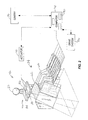
- FIG. 1 illustrates a radiation therapy treatment system 10 that can provide radiation therapy to a patient 14.
- the radiation therapy treatment can include photon-based radiation therapy, brachytherapy, electron beam therapy, proton, neutron, or particle therapy, or other types of treatment therapy.
- the radiation therapy treatment system 10 includes a gantry 18.
- the gantry 18 can support a radiation module 22, which can include a radiation source 24 and a linear accelerator 26 operable to generate a beam 30 of radiation.
- the gantry 18 shown in the drawings is a ring gantry, i.e., it extends through a full 360° arc to create a complete ring or circle, other types of mounting arrangements may also be employed.
- a C-type, partial ring gantry, or robotic arm could be used.
- the radiation source 24 may travel in path that does not follow the shape of the gantry 18.
- the radiation source 24 may travel in a non-circular path even though the illustrated gantry 18 is generally circular-shaped.
- the radiation module 22 can also include a modulation device 34 operable to modify or modulate the radiation beam 30.
- the modulation device 34 provides the modulation of the radiation beam 30 and directs the radiation beam 30 toward the patient 14.
- the radiation beam 34 is directed toward a portion of the patient.
- the portion may include the entire body, but is generally smaller than the entire body and can be defined by a two-dimensional area and/or a three-dimensional volume.
- a portion desired to receive the radiation which may be referred to as a target 38 or target region, is an example of a region of interest.
- Another type of region of interest is a region at risk. If a portion includes a region at risk, the radiation beam is preferably diverted from the region at risk.
- the patient 14 may have more than one target region that needs to receive radiation therapy. Such modulation is sometimes referred to as intensity modulated radiation therapy ("IMRT").
- IMRT intensity modulated radiation therapy
- the modulation device 34 can include a collimation device 42 as illustrated in FIG. 2 .
- the collimation device 42 includes a set of jaws 46 that define and adjust the size of an aperture 50 through which the radiation beam 30 may pass.
- the jaws 46 include an upper jaw 54 and a lower jaw 58.
- the upper jaw 54 and the lower jaw 58 are moveable to adjust the size of the aperture 50.
- the modulation device 34 can comprise a multi-leaf collimator 62, which includes a plurality of interlaced leaves 66 operable to move from position to position, to provide intensity modulation. It is also noted that the leaves 66 can be moved to a position anywhere between a minimally and maximally-open position. The plurality of interlaced leaves 66 modulate the strength, size, and shape of the radiation beam 30 before the radiation beam 30 reaches the target 38 on the patient 14. Each of the leaves 66 is independently controlled by an actuator 70, such as a motor or an air valve so that the leaf 66 can open and close quickly to permit or block the passage of radiation.
- the actuators 70 can be controlled by a computer 74 and/or controller.
- the radiation therapy treatment system 10 can also include a detector 78, e.g., a kilovoltage or a megavoltage detector, operable to receive the radiation beam 30.
- the linear accelerator 26 and the detector 78 can also operate as a computed tomography (CT) system to generate CT images of the patient 14.
- CT computed tomography
- the linear accelerator 26 emits the radiation beam 30 toward the target 38 in the patient 14.
- the target 38 absorbs some of the radiation.
- the detector 78 detects or measures the amount of radiation absorbed by the target 38.
- the detector 78 collects the absorption data from different angles as the linear accelerator 26 rotates around and emits radiation toward the patient 14.
- the collected absorption data is transmitted to the computer 74 to process the absorption data and to generate images of the patient's body tissues and organs.
- the images can also illustrate bone, soft tissues, and blood vessels.
- the CT images can be acquired with a radiation beam 30 that has a fan-shaped geometry, a multi-slice geometry or a cone-beam geometry.
- the CT images can be acquired with the linear accelerator 26 delivering megavoltage energies or kilovoltage energies.
- the acquired CT images can be registered with previously acquired CT images (from the radiation therapy treatment system 10 or other image acquisition devices, such as other CT scanners, MRI systems, and PET systems).
- the previously acquired CT images for the patient 14 can include identified targets 38 made through a contouring process.
- the newly acquired CT images for the patient 14 can be registered with the previously acquired CT images to assist in identifying the targets 38 in the new CT images.
- the registration process can use rigid or deformable registration tools.
- the radiation therapy treatment system 10 can include an x-ray source and a CT image detector.
- the x-ray source and the CT image detector operate in a similar manner as the linear accelerator 26 and the detector 78 as described above to acquire image data.
- the image data is transmitted to the computer 74 where it is processed to generate images of the patient's body tissues and organs.
- the radiation therapy treatment system 10 can also include a patient support, such as a couch 82 (illustrated in FIG. 1 ), which supports the patient 14.
- the couch 82 moves along at least one axis 84 in the x, y, or z directions.
- the patient support can be a device that is adapted to support any portion of the patient's body.
- the patient support is not limited to having to support the entire patient's body.
- the system 10 also can include a drive system 86 operable to manipulate the position of the couch 82.
- the drive system 86 can be controlled by the computer 74.
- the computer 74 illustrated in FIGS. 2 and 3 , includes an operating system for running various software programs and/or a communications application.
- the computer 74 can include a software program(s) 90 that operates to communicate with the radiation therapy treatment system 10.
- the software program(s) 90 is operable to receive data from external software programs and hardware and it is noted that data may be input to the software program(s) 90.
- the computer 74 can include any suitable input/output device adapted to be accessed by medical personnel.
- the computer 74 can include typical hardware such as a processor, I/O interfaces, and storage devices or memory.
- the computer 74 can also include input devices such as a keyboard and a mouse.
- the computer 74 can further include standard output devices, such as a monitor.
- the computer 74 can include peripherals, such as a printer and a scanner.
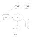
- the computer 74 can be networked with other computers 74 and radiation therapy treatment systems 10.
- the other computers 74 may include additional and/or different computer programs and software and are not required to be identical to the computer 74, described herein.
- the computers 74 and radiation therapy treatment system 10 can communicate with a network 94.
- the computers 74 and radiation therapy treatment systems 10 can also communicate with a database(s) 98 and a server(s) 102. It is noted that the software program(s) 90 could also reside on the server(s) 102.
- the network 94 can be built according to any networking technology or topology or combinations of technologies and topologies and can include multiple sub-networks. Connections between the computers and systems shown in FIG. 3 can be made through local area networks ("LANs”), wide area networks (“WANs”), public switched telephone networks (“PSTNs”), wireless networks, Intranets, the Internet, or any other suitable networks. In a hospital or medical care facility, communication between the computers and systems shown in FIG. 3 can be made through the Health Level Seven (“HL7”) protocol or other protocols with any version and/or other required protocol. HL7 is a standard protocol which specifies the implementation of interfaces between two computer applications (sender and receiver) from different vendors for electronic data exchange in health care environments.
- HL7 Health Level Seven
- HL7 can allow health care institutions to exchange key sets of data from different application systems. Specifically, HL7 can define the data to be exchanged, the timing of the interchange, and the communication of errors to the application.
- the formats are generally generic in nature and can be configured to meet the needs of the applications involved.
- DICOM Digital Imaging and Communications in Medicine
- the two-way arrows in FIG. 3 generally represent two-way communication and information transfer between the network 94 and any one of the computers 74 and the systems 10 shown in FIG. 3 . However, for some medical and computerized equipment, only one-way communication and information transfer may be necessary.
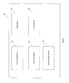
- the software program 90 includes a plurality of modules illustrated in FIG. 4 that communicate with one another to perform functions of the radiation therapy treatment process.
- the various modules communicate with one another to generate a deformation map of two images and to modify the deformation map in response to various modifications of one of the images. Generally, the deformation process occurs prior to commencing treatment delivery. It is noted that not all of the modules discussed below are needed to communicate and to carry out the various functions mentioned above.
- the software program 90 includes a treatment plan module 106 operable to generate a treatment plan for the patient 14 based on data input to the system 10 by medical personnel.
- the data includes one or more images (e.g., planning images and/or pre-treatment images) of at least a portion of the patient 14.
- the treatment plan module 106 separates the treatment into a plurality of fractions and determines the radiation dose for each fraction or treatment based on the prescription input by medical personnel.
- the treatment plan module 106 also determines the radiation dose for the target 38 based on various contours drawn around the target 38. Multiple targets 38 maybe present and included in the same treatment plan.
- the software program 90 also includes an image module 110 operable to acquire images of at least a portion of the patient 14.
- the image module 110 can instruct the on-board image device, such as a CT imaging device to acquire one or more pre-treatment images of the patient 14 before treatment commences.
- Other off-line imaging devices or systems may be used to acquire pre-treatment images of the patient 14, such as non-quantitative CT, MRI, PET, SPECT, ultrasound, transmission imaging, fluoroscopy, RF-based localization, and the like.
- the acquired pre-treatment image(s) can be used for registration of the patient 14 and/or to generate a deformation map to identify the differences between one or more of the planning images and one or more of the pre-treatment images.
- the software program 90 also can include a deformation module 114 operable to receive data, such as image data from the image module 110 and the treatment planning module 106 and other patient and system data from the treatment plan module 106 to generate a deformation map of the images.
- the deformation module 114 can use deformation techniques to determine an accumulation of radiation dose for all of the delivered treatments.
- a deformation map can be utilized to relate a plurality of images for dose calculation purposes.
- a deformation map can relate a planning image that is useful for dose calculation, and an on-line image, which has qualitative value but less direct utility for dose calculation. This relationship can then be used to "remap" the more quantitative image to the qualitative shape of the on-line or less quantitative image. The resulting remapped image would be more appropriate than either of the planning image or the on-line image for dose calculation or quantitative applications as it would have the quantitative benefits of the first image, but with the updated anatomical information as contained in the second image.
- a deformation map also can relate a reference image, such as a 3D image (e.g., a planning image or a pre-treatment image), and a time-based series of images, such as a 4D CT image to determine an amount of radiation dose delivered to the patient 14.
- a reference image such as a 3D image (e.g., a planning image or a pre-treatment image)
- a time-based series of images such as a 4D CT image to determine an amount of radiation dose delivered to the patient 14.
- the deformation module 114 can correct for geometrical distortion, imperfections, and/or incompleteness in lieu of, or in addition to, quantitative limitations. For example, a current MRI image that represents anatomy well but includes geometric distortion might be remapped to a CT image that is not distorted. Or, multiple images can be used to simultaneously correct for distortion while representing anatomical changes.
- the deformation map can be used to calculate radiation dose on patient images acquired after the planning image. It is also useful to accumulate the doses for multiple delivered fractions. The doses can be added based upon the location of the doses in physical space, but another method is to incorporate deformation methods into the process so as to add doses based upon the structures that received the dose, even if the structures have changed location.
- the deformation module 114 can calculate the doses of radiation that the patient 14 has received from previously delivered fractions.
- a deformation map can be generated for purposes of defining a contour around a target 38.
- the software program 90 can include a contour module 118 operable to generate one or more contours on an image.
- a contour module 118 operable to generate one or more contours on an image.
- medical personnel manually define a contour around a target 38 on a planning image. This process is time consuming. Newly acquired images (e.g., pre-treatment images) do not have the defined contour(s). It is desirable to generate contours on the new image based upon an old image that includes the contour(s).
- a deformation map can be used to assist in the contouring process by transferring the contour(s) from an old image onto a new image and can create time savings for the medical personnel while providing quality assurance measures.
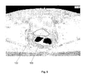
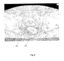
- FIGS. 5-10 illustrate the use of a deformation map to apply contours from a planning image onto a newly-acquired image. This process begins with a planning or other baseline patient image that has an initial contour set.
- FIG. 5 illustrates a planning KVCT with a contour 122 around the prostate and a contour 126 around the rectum of a patient.
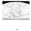
- FIG. 6 illustrates a pre-treatment image of the same patient illustrated in FIG. 5 .
- the image includes a manually-drawn contour 130 around the prostate and a manually-drawn contour 134 around the rectum of the patient for purposes of evaluating automatically generated contours using deformable registration.
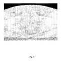
- FIG. 7 illustrates displacement vectors resulting from a deformable registration between the image in FIG. 5 and the image in FIG. 6 .
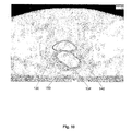
- FIGS. 9 and 10 illustrates an automatically generated contour 138 around the prostate and an automatically generated contour 142 around the rectum, and for comparison purposes, the manually-drawn contours 130 and 134 are also shown. Focusing on the rectum portion of the images, if the manually-drawn contour 134 is used as a constraint for the deformable registration then the resulting deformable registration between the image in FIG. 5 and the image in FIG. 6 is illustrated in FIGS. 9 and 10 . A newly-added contour 146 (dashed line) around the prostate more closely resembles the manually-drawn contour 130. Similarly, a newly-added contour 150 (dashed line) around the rectum more closely resembles the manually-drawn contour 134. It is generally known that manual contours can suffer from irreproducibilities, whereas automatically generated contours can potentially be more consistent in applying the principles of an initial contour to the generation of subsequent contours.
- a similar family of template-based contouring algorithms has been developed to generate contours for newly-available images, based upon previously available sets of images and contours.
- These template-based algorithms might contour a new patient image based upon a previous patient image and contour, or potentially based upon a canonical or atlas patient image and contour. This can be performed for adaptive therapy as a means to accumulate doses in daily images, each with automatic daily contours.
- this includes deformation and template-based contouring of multiple images of the same patient in which contour sets might only exist for one of the images.
- These multiple images of the patient may arise from use of an on-line or in-room patient imaging system, with images potentially taken on different days, or these images might derive from a "4D" imaging system such as a CT scanner, in which each image represents a phase of motion, such as a breathing phase.
- a "4D" imaging system such as a CT scanner
- each image represents a phase of motion, such as a breathing phase.
- the on-line or in-room imaging system might be the same, a similar, or a different modality from the reference image.
- the reference image might be a CT image
- the on-line image could be a CT image, a cone-beam CT image, a megavoltage CT image, a MRI image, an ultrasound image, or an image generated by a different system or device.
- the contours generated provide a validation of the deformation process. If the generated contours closely reflect contours that one would manually draw, then it is a good indication that the deformation process is reasonable; whereas if the automatic contours are less relevant, it indicates to the medical personnel that perhaps the deformation is inappropriate, but also provides the medical personnel an opportunity to verify the manual contours to check for mistakes or inconsistencies.
- the deformation-based contours can be used as a rough-draft of the contours for the adaptive process, and manually edited to reflect the desired contours for the on-line images. When doing this, the deformation process can then be re-run, constraining the deformation map to match the initial contours to the manually-edited automatic contours, and this helps direct consistent results through the rest of the image.
- the deformation process above was described in the context of registering one image to another image, it can also work with deformably registering a set of two or more images with another set of one or more images. For example, if there are two pairs of images, each pair comprising an MRI and a CT image, then the deformation map can register the two MRI images together in regions where the MRI has more information, and the CT images together where the CT has more information. These deformations could then be combined.
- deformation maps between the images could be used together, such as for using the CT deformation maps to correct for geometric distortion, imperfections, and/or incompleteness in the MRI images and deformations, and then, having corrected that distortion, imperfection, and/or incompleteness using the MRI deformation maps for better analysis of soft-tissue motion.
- this process enables imaging improvement via deformation, as poor images can be better understood, and therefore improved, by applying deformation techniques that indicate information like anatomical sizes, shapes, and content. This information can be incorporated into image reconstruction, modification, or enhancement processes.
- the software program 90 also includes a treatment delivery module 154 operable to instruct the radiation therapy treatment system 10 to deliver radiation therapy to the patient 14 according to the treatment plan.
- the treatment delivery module 154 can generate and transmit instructions to the gantry 18, the linear accelerator 26, the modulation device 34, and the drive system 86 to deliver radiation to the patient 14.
- the instructions coordinate the necessary movements of the gantry 18, the modulation device 34, and the drive system 86 to deliver the radiation beam 30 to the proper target in the proper amount as specified in the treatment plan.
- the treatment delivery module 154 also calculates the appropriate pattern, position, and intensity of the radiation beam 30 to be delivered, to match the prescription as specified by the treatment plan.
- the pattern of the radiation beam 30 is generated by the modulation device 34, and more particularly by movement of the plurality of leaves in the multi-leaf collimator.
- the treatment delivery module 154 can utilize canonical, predetermined or template leaf patterns to generate the appropriate pattern for the radiation beam 30 based on the treatment parameters.
- the treatment delivery module 154 can also include a library of patterns for typical cases that can be accessed in which to compare the present patient data to determine the pattern for the radiation beam 30.
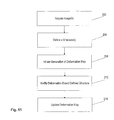
- FIG. 11 illustrates a flow chart of a method of placing constraints on a deformation map.
- Medical personnel initiate acquisition (at 200) of one or more images (e.g., a planning image) of at least a portion of the patient 14.
- medical personnel identify or define (at 204) one or more structures in the one or more images of the patient 14 using one or more contours or other identification tools.
- the defined structure is typically a target 38 in the one or more images.
- the medical personnel initiate (at 208) the generation of a deformation map between two or more of the previously acquired images with the deformation module 114 to relate the defined structure from the one image onto the other image to create a deformation-based defined structure.
- the medical personnel can modify (at 212) the deformation-based defined structure and initiate (at 216) the deformation module 114 to update the deformation map based on the modified deformation-based defined structure.
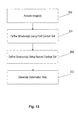
- FIG. 12 illustrates a flow chart of a method of placing constraints on a deformation map.
- Medical personnel initiate acquisition (at 250) of one or more images (e.g., a planning image) of at least a portion of the patient 14.
- medical personnel identify or define (at 254) one or more structures in the one or more images of the patient 14 using one or more contours or other identification tools.
- the defined structure is typically a target 38 in the one or more images.
- the medical personnel initiate (at 258) the generation of a deformation map between two or more of the previously acquired images with the deformation module 114 to relate the defined structure from the one image onto the other image to create a deformation-based defined structure.
- the medical personnel can modify (at 262) the deformation-based defined structure and initiate (at 266) the deformation module 114 to update the deformation map based on the modified deformation-based defined structure.
- the contour module 118 Based on the updated deformation map, the contour module 118 generates (at 270) a contour on one of the images.
- FIG. 13 illustrates a flow chart of a method of placing constraints on a deformation map.
- Medical personnel initiate acquisition (at 300) of one or more images (e.g., a planning image) of at least a portion of the patient 14.
- medical personnel identify or define (at 304) one or more structures in the one or more images of the patient 14 using a first contour set or other identification tools.
- the defined structure is typically a target 38 in the one or more images.
- Medical personnel identify or define (at 308) or further define one or more structures in the one or more images of the patient 14 using a second contour set or other identification tools.
- the medical personnel initiate (at 312) the generation of a deformation map between the first contour set and the second contour set to identify the differences between the contour sets.
Description
- Over the past decades improvements in computers and networking, radiation therapy treatment planning software, and medical imaging modalities (CT, MRI, US, and PET) have been incorporated into radiation therapy practice. These improvements have led to the development of image guided radiation therapy ("IGRT"). IGRT is radiation therapy that uses cross-sectional images of the patient's internal anatomy to better target the radiation dose in the tumor while reducing the radiation exposure to healthy organs. The radiation dose delivered to the tumor is controlled with intensity modulated radiation therapy ("IMRT"), which involves changing the size, shape, and intensity of the radiation beam to conform to the size, shape, and location of the patient's tumor. IGRT and IMRT lead to improved control of the tumor while simultaneously reducing the potential for acute side effects due to irradiation of healthy tissue surrounding the tumor.
- IMRT is becoming the standard of care in several countries. However, in many situations, IMRT is not used to treat a patient due to time, resources, and billing constraints. Daily images of the patient can be used to guarantee that the high gradients generated by IMRT plans are located on the correct position for patient treatment. Also these images can provide necessary information to adapt the plan online or offline if needed.
- It is commonly known in the field of radiation therapy that there are many sources of uncertainty and change that can occur during a course of a patient's treatment. Some of these sources represent random errors, such as small differences in a patient's setup position each day. Other sources are attributable to physiological changes, which might occur if a patient's tumor regresses or the patient loses weight during therapy. A third possible category regards motion. Motion can potentially overlap with either of the other categories, as some motion might be more random and unpredictable, such as a patient coughing or passing gas, whereas other motion can be more regular, such as breathing motion, sometimes.
- A technique for non-rigid registration of contrast-enhanced breast MRI is disclosed in 'Non-rigid Registration Using Free-Form Deformations: Application to Breast MR Images.' IEEE Transactions on Medical Imaging, vol. 18, no. 8, August 1999, pgs. 712 - 721. The global motion of the breast is modelled by an affline transformation, while the local breast motion is described by a free-form deformation FF based on B-splines. Image registration is achieved by minimising a cost function, which represents a combination of the cost associated with the smoothness of the transformation and the cost associated with the image similarity.
- In radiation therapy, uncertainties can affect the quality of a patient's treatment. For example, when delivering a treatment dose to a target region, it is standard practice to also treat a high-dose "margin" region about the target. This helps ensure that the target receives the desired dose, even if its location changes during the course of the treatment, or even during a single fraction. The less definite a target's location, the larger the margins that typically need to be used.
- Adaptive radiation therapy generally refers to the concept of using feedback during the course of radiation therapy treatment to improve future treatments. Feedback can be used in off-line adaptive therapy processes and on-line adaptive therapy processes. Offline adaptive therapy processes occur while the patient is not being treated, such as in between treatment fractions. In one version of this, during each fraction, a new CT image of the patient is acquired before or after each of the fractions. After the images are acquired from the first few treatment fractions, the images are evaluated to determine an effective envelope of the multi-day locations of target structures. A new plan can then be developed to better reflect the range of motion of the target structure, rather than using canonical assumptions of motion. A more complex version of off-line adaptive therapy is to recalculate the delivered dose after each fraction and accumulate these doses, potentially utilizing deformation techniques, during this accumulation to account for internal motion. The accumulated dose can then be compared to the planned dose, and if any discrepancies are noted, subsequent fractions can be modified to account for the changes.
- On-line adaptive therapy processes typically occur while the patient is in the treatment room, and potentially, but not necessarily, during a treatment delivery. For example, some radiation therapy treatment systems are equipped with imaging systems, such as on-line CT or x-ray systems. These systems can be used prior to treatment to validate or adjust the patient's setup for the treatment delivery. The imaging systems may also be used to adapt the treatment during the actual treatment delivery. For example, an imaging system potentially can be used concurrently with treatment to modify the treatment delivery to reflect changes in patient anatomy.
- One aspect of the present invention is to disclose new opportunities for the application of adaptive therapy techniques, and additional aspects are to present novel methods for adaptive therapy. In particular, adaptive therapy has typically focused on feedback to modify a patient's treatment, but the present invention focuses on adaptive therapy processes being used in a quality assurance context. This is particularly true in the context of whole-system verification.
- For example, a detector can be used to collect information indicating how much treatment beam has passed through the patient, from which the magnitude of the treatment output can be determined as well as any radiation pattern that was used for the delivery. The benefit of this delivery verification process is that it enables the operator to detect errors in the machine delivery, such as an incorrect leaf pattern or machine output.
- However, validating that the machine is functioning properly does not itself ensure proper delivery of a treatment plan, as one also needs to validate that the external inputs used to program the machine are effective and consistent. Thus, one aspect of the invention includes the broader concept of an adaptive-type feedback loop for improved quality assurance of the entire treatment process. In this aspect, the invention includes the steps of positioning the patient for treatment and using a method for image-guidance to determine the patient's position, repositioning the patient as necessary for treatment based upon the image-guidance, and beginning treatment. Then, either during or after treatment, recalculating the patient dose and incorporating the patient image information that had been collected before or during treatment. After completion of these steps, quality assurance data is collected to analyze the extent to which the delivery was not only performed as planned, but to validate that the planned delivery is reasonable in the context of the newly available data. In this regard, the concept of feedback is no longer being used to indicate changes to the treatment based on changes in the patient or delivery, but to validate the original delivery itself.
- As an example, it is possible that a treatment plan might be developed for a patient, but that the image used for planning became corrupted, such as by applying an incorrect density calibration. In this case, the treatment plan will be based upon incorrect information, and might not deliver the correct dose to the patient. Yet, many quality assurance techniques will not detect this error because they will verify that the machine is operating as instructed, rather than checking whether the instructions to the machine are based on correct input information. Likewise, some adaptive therapy techniques could be applied to this delivery, but if the calibration problem of this example persisted, then the adapted treatments would suffer from similar flaws.
- There are a number of processes that can be used to expand the use of feedback for quality assurance purposes. For example, in one embodiment, this process would include the delivery verification techniques described above. The validation of machine performance that these methods provide is a valuable component of a total-system quality assurance toolset. Moreover, the delivery verification processes can be expanded to analyze other system errors, such as deliveries based on images with a truncated field-of-view.
- This method of quality assurance also benefits from the use of registration, and in particular, deformable registration, techniques. Registration is a method for determining the correlation between locations of a patient's anatomy or physiology across multiple images, and deformable registration is a method of doing this to account for non-rigid changes in anatomy between the images, phases, or times. As mentioned before, an important step in this method of quality assurance is the recalculation of dose based upon on-line images and feedback from the machine. When analyzing these doses, it is useful to accumulate the dose across multiple treatments to determine if any errors are being exacerbated or if they are mitigating each other.
- It should be noted that while the invention presented is not fundamentally tied to adaptive therapy, in that these quality assurance processes can be applied without an adaptive therapy process in place, or adaptive therapy can be performed without these QA methods, there can be added benefits to using adaptive therapy in addition to these techniques. Therefore, if discrepancies are noted by using delivery feedback, these discrepancies can be rectified by any number of mechanisms either on-line or between fractions. The discrepancies to be remedied can extend beyond problems identified with the machine itself, for example, to inconsistencies with the process, or flawed inputs that are used to program the machine for a given treatment plan.
- In one embodiment, the invention provides a method of placing constraints on a deformation, the invention being as defined in the appended claims . The method comprises the acts of generating a deformation map between two images, identifying a defined structure in one of the images, applying the deformation map to relate the defined structure from the one image onto the other image to create a deformation-based defined structure, modifying the deformation-based defined structure, and updating the deformation map in response to the step of modifying the deformation-based defined structure.
- In another embodiment, the invention provides a method of placing constraints on a deformation map. The method comprises the acts of generating a deformation map between two images, identifying a defined structure in one of the images, applying the deformation map to relate the defined structure from the one image onto the other image to create a deformation-based defined structure, modifying the deformation-based defined structure, updating the deformation map in response to the step of modifying the deformation-based defined structure, and generating a contour based on the updated deformation map.
-
-
FIG. 1 is a perspective view of a radiation therapy treatment system embodying the invention. -
FIG. 2 is a perspective view of a multi-leaf collimator that can be used in the radiation therapy treatment system illustrated inFIG. 1 . -
FIG. 3 is a schematic illustration of the radiation therapy treatment system ofFIG. 1 . -
FIG. 4 is a schematic diagram of a software program used in the radiation therapy treatment system of a method of placing constraints on a deformation map according to one embodiment of the present invention. -
FIG. 5 is a planning image of a patient including contours. -
FIG. 6 is a pre-treatment image of a patient including manually-drawn contours. -
FIG. 7 is a deformation map between the images inFIGS. 5-6 . -
FIG. 8 is a resulting image of the patient including contours after applying the deformation map illustrated inFIG. 7 . -
FIG. 9 is a deformation map using the manually-drawn contour ofFIG. 6 as a constraint. -
FIG. 10 is a resulting image of the patient including contours after applying the deformation map illustrated inFIG. 9 . -
FIG. 11 is a flow chart of a method of placing constraints on a deformation map according to one embodiment of the present invention. -
FIG. 12 is a flow chart of a method of placing constraints on a deformation map according to one embodiment of the present invention. -
FIG. 13 is a flow chart of a method of placing constraints on a deformation map according to one embodiment of the present invention. - Before any embodiments of the invention are explained in detail, it is to be understood that the invention is not limited in its application to the details of construction and the arrangement of components set forth in the following description or illustrated in the following drawings. The invention is capable of other embodiments and of being practiced or of being carried out in various ways. Also, it is to be understood that the phraseology and terminology used herein is for the purpose of description and should not be regarded as limiting. The use of "including," "comprising," or "having" and variations thereof herein is meant to encompass the items listed thereafter and equivalents thereof as well as additional items. Unless specified or limited otherwise, the terms "mounted," "connected," "supported," and "coupled" and variations thereof are used broadly and encompass both direct and indirect mountings, connections, supports, and couplings. Further, "connected" and "coupled" are not restricted to physical or mechanical connections or couplings.
- Although directional references, such as upper, lower, downward, upward, rearward, bottom, front, rear, etc., may be made herein in describing the drawings, these references are made relative to the drawings (as normally viewed) for convenience. These directions are not intended to be taken literally or limit the present invention in any form. In addition, terms such as "first", "second", and "third" are used herein for purposes of description and are not intended to indicate or imply relative importance or significance.
- In addition, it should be understood that embodiments of the invention include both hardware, software, and electronic components or modules that, for purposes of discussion, may be illustrated and described as if the majority of the components were implemented solely in hardware. However, one of ordinary skill in the art, and based on a reading of this detailed description, would recognize that, in at least one embodiment, the electronic based aspects of the invention may be implemented in software. As such, it should be noted that a plurality of hardware and software based devices, as well as a plurality of different structural components may be utilized to implement the invention. Furthermore, and as described in subsequent paragraphs, the specific mechanical configurations illustrated in the drawings are intended to exemplify embodiments of the invention and that other alternative mechanical configurations are possible.
-
FIG. 1 illustrates a radiationtherapy treatment system 10 that can provide radiation therapy to apatient 14. The radiation therapy treatment can include photon-based radiation therapy, brachytherapy, electron beam therapy, proton, neutron, or particle therapy, or other types of treatment therapy. The radiationtherapy treatment system 10 includes agantry 18. Thegantry 18 can support aradiation module 22, which can include aradiation source 24 and alinear accelerator 26 operable to generate abeam 30 of radiation. Though thegantry 18 shown in the drawings is a ring gantry, i.e., it extends through a full 360° arc to create a complete ring or circle, other types of mounting arrangements may also be employed. For example, a C-type, partial ring gantry, or robotic arm could be used. Any other framework capable of positioning theradiation module 22 at various rotational and/or axial positions relative to the patient 14 may also be employed. In addition, theradiation source 24 may travel in path that does not follow the shape of thegantry 18. For example, theradiation source 24 may travel in a non-circular path even though the illustratedgantry 18 is generally circular-shaped. - The
radiation module 22 can also include amodulation device 34 operable to modify or modulate theradiation beam 30. Themodulation device 34 provides the modulation of theradiation beam 30 and directs theradiation beam 30 toward thepatient 14. Specifically, theradiation beam 34 is directed toward a portion of the patient. Broadly speaking, the portion may include the entire body, but is generally smaller than the entire body and can be defined by a two-dimensional area and/or a three-dimensional volume. A portion desired to receive the radiation, which may be referred to as atarget 38 or target region, is an example of a region of interest. Another type of region of interest is a region at risk. If a portion includes a region at risk, the radiation beam is preferably diverted from the region at risk. The patient 14 may have more than one target region that needs to receive radiation therapy. Such modulation is sometimes referred to as intensity modulated radiation therapy ("IMRT"). - The
modulation device 34 can include acollimation device 42 as illustrated inFIG. 2 . Thecollimation device 42 includes a set ofjaws 46 that define and adjust the size of anaperture 50 through which theradiation beam 30 may pass. Thejaws 46 include anupper jaw 54 and alower jaw 58. Theupper jaw 54 and thelower jaw 58 are moveable to adjust the size of theaperture 50. - In one embodiment, and illustrated in
FIG. 2 , themodulation device 34 can comprise amulti-leaf collimator 62, which includes a plurality of interlaced leaves 66 operable to move from position to position, to provide intensity modulation. It is also noted that the leaves 66 can be moved to a position anywhere between a minimally and maximally-open position. The plurality of interlaced leaves 66 modulate the strength, size, and shape of theradiation beam 30 before theradiation beam 30 reaches thetarget 38 on thepatient 14. Each of the leaves 66 is independently controlled by anactuator 70, such as a motor or an air valve so that the leaf 66 can open and close quickly to permit or block the passage of radiation. Theactuators 70 can be controlled by acomputer 74 and/or controller. - The radiation
therapy treatment system 10 can also include adetector 78, e.g., a kilovoltage or a megavoltage detector, operable to receive theradiation beam 30. Thelinear accelerator 26 and thedetector 78 can also operate as a computed tomography (CT) system to generate CT images of thepatient 14. Thelinear accelerator 26 emits theradiation beam 30 toward thetarget 38 in thepatient 14. Thetarget 38 absorbs some of the radiation. Thedetector 78 detects or measures the amount of radiation absorbed by thetarget 38. Thedetector 78 collects the absorption data from different angles as thelinear accelerator 26 rotates around and emits radiation toward thepatient 14. The collected absorption data is transmitted to thecomputer 74 to process the absorption data and to generate images of the patient's body tissues and organs. The images can also illustrate bone, soft tissues, and blood vessels. - The CT images can be acquired with a
radiation beam 30 that has a fan-shaped geometry, a multi-slice geometry or a cone-beam geometry. In addition, the CT images can be acquired with thelinear accelerator 26 delivering megavoltage energies or kilovoltage energies. It is also noted that the acquired CT images can be registered with previously acquired CT images (from the radiationtherapy treatment system 10 or other image acquisition devices, such as other CT scanners, MRI systems, and PET systems). For example, the previously acquired CT images for the patient 14 can include identifiedtargets 38 made through a contouring process. The newly acquired CT images for the patient 14 can be registered with the previously acquired CT images to assist in identifying thetargets 38 in the new CT images. The registration process can use rigid or deformable registration tools. - In some embodiments, the radiation
therapy treatment system 10 can include an x-ray source and a CT image detector. The x-ray source and the CT image detector operate in a similar manner as thelinear accelerator 26 and thedetector 78 as described above to acquire image data. The image data is transmitted to thecomputer 74 where it is processed to generate images of the patient's body tissues and organs. - The radiation
therapy treatment system 10 can also include a patient support, such as a couch 82 (illustrated inFIG. 1 ), which supports thepatient 14. Thecouch 82 moves along at least oneaxis 84 in the x, y, or z directions. In other embodiments of the invention, the patient support can be a device that is adapted to support any portion of the patient's body. The patient support is not limited to having to support the entire patient's body. Thesystem 10 also can include a drive system 86 operable to manipulate the position of thecouch 82. The drive system 86 can be controlled by thecomputer 74. - The
computer 74, illustrated inFIGS. 2 and3 , includes an operating system for running various software programs and/or a communications application. In particular, thecomputer 74 can include a software program(s) 90 that operates to communicate with the radiationtherapy treatment system 10. The software program(s) 90 is operable to receive data from external software programs and hardware and it is noted that data may be input to the software program(s) 90. - The
computer 74 can include any suitable input/output device adapted to be accessed by medical personnel. Thecomputer 74 can include typical hardware such as a processor, I/O interfaces, and storage devices or memory. Thecomputer 74 can also include input devices such as a keyboard and a mouse. Thecomputer 74 can further include standard output devices, such as a monitor. In addition, thecomputer 74 can include peripherals, such as a printer and a scanner. - The
computer 74 can be networked withother computers 74 and radiationtherapy treatment systems 10. Theother computers 74 may include additional and/or different computer programs and software and are not required to be identical to thecomputer 74, described herein. Thecomputers 74 and radiationtherapy treatment system 10 can communicate with anetwork 94. Thecomputers 74 and radiationtherapy treatment systems 10 can also communicate with a database(s) 98 and a server(s) 102. It is noted that the software program(s) 90 could also reside on the server(s) 102. - The
network 94 can be built according to any networking technology or topology or combinations of technologies and topologies and can include multiple sub-networks. Connections between the computers and systems shown inFIG. 3 can be made through local area networks ("LANs"), wide area networks ("WANs"), public switched telephone networks ("PSTNs"), wireless networks, Intranets, the Internet, or any other suitable networks. In a hospital or medical care facility, communication between the computers and systems shown inFIG. 3 can be made through the Health Level Seven ("HL7") protocol or other protocols with any version and/or other required protocol. HL7 is a standard protocol which specifies the implementation of interfaces between two computer applications (sender and receiver) from different vendors for electronic data exchange in health care environments. HL7 can allow health care institutions to exchange key sets of data from different application systems. Specifically, HL7 can define the data to be exchanged, the timing of the interchange, and the communication of errors to the application. The formats are generally generic in nature and can be configured to meet the needs of the applications involved. - Communication between the computers and systems shown in
FIG. 3 can also occur through the Digital Imaging and Communications in Medicine ("DICOM") protocol with any version and/or other required protocol. DICOM is an international communications standard developed by NEMA that defines the format used to transfer medical image-related data between different pieces of medical equipment. DICOM RT refers to the standards that are specific to radiation therapy data. - The two-way arrows in
FIG. 3 generally represent two-way communication and information transfer between thenetwork 94 and any one of thecomputers 74 and thesystems 10 shown inFIG. 3 . However, for some medical and computerized equipment, only one-way communication and information transfer may be necessary. - The
software program 90 includes a plurality of modules illustrated inFIG. 4 that communicate with one another to perform functions of the radiation therapy treatment process. The various modules communicate with one another to generate a deformation map of two images and to modify the deformation map in response to various modifications of one of the images. Generally, the deformation process occurs prior to commencing treatment delivery. It is noted that not all of the modules discussed below are needed to communicate and to carry out the various functions mentioned above. - The
software program 90 includes atreatment plan module 106 operable to generate a treatment plan for the patient 14 based on data input to thesystem 10 by medical personnel. The data includes one or more images (e.g., planning images and/or pre-treatment images) of at least a portion of thepatient 14. Thetreatment plan module 106 separates the treatment into a plurality of fractions and determines the radiation dose for each fraction or treatment based on the prescription input by medical personnel. Thetreatment plan module 106 also determines the radiation dose for thetarget 38 based on various contours drawn around thetarget 38.Multiple targets 38 maybe present and included in the same treatment plan. - The
software program 90 also includes animage module 110 operable to acquire images of at least a portion of thepatient 14. Prior to delivery of the treatment plan, theimage module 110 can instruct the on-board image device, such as a CT imaging device to acquire one or more pre-treatment images of the patient 14 before treatment commences. Other off-line imaging devices or systems may be used to acquire pre-treatment images of thepatient 14, such as non-quantitative CT, MRI, PET, SPECT, ultrasound, transmission imaging, fluoroscopy, RF-based localization, and the like. The acquired pre-treatment image(s) can be used for registration of thepatient 14 and/or to generate a deformation map to identify the differences between one or more of the planning images and one or more of the pre-treatment images. - The
software program 90 also can include adeformation module 114 operable to receive data, such as image data from theimage module 110 and thetreatment planning module 106 and other patient and system data from thetreatment plan module 106 to generate a deformation map of the images. Thedeformation module 114 can use deformation techniques to determine an accumulation of radiation dose for all of the delivered treatments. - A deformation map can be utilized to relate a plurality of images for dose calculation purposes. For example, a deformation map can relate a planning image that is useful for dose calculation, and an on-line image, which has qualitative value but less direct utility for dose calculation. This relationship can then be used to "remap" the more quantitative image to the qualitative shape of the on-line or less quantitative image. The resulting remapped image would be more appropriate than either of the planning image or the on-line image for dose calculation or quantitative applications as it would have the quantitative benefits of the first image, but with the updated anatomical information as contained in the second image. This is useful in a variety of cases, such as where the first image (e.g., a planning image) is a CT image and where the second image lacks quantitative image values (e.g., MRI, PET, SPECT, ultrasound, or non-quantitative CT, etc. images). A deformation map also can relate a reference image, such as a 3D image (e.g., a planning image or a pre-treatment image), and a time-based series of images, such as a 4D CT image to determine an amount of radiation dose delivered to the
patient 14. - The
deformation module 114 can correct for geometrical distortion, imperfections, and/or incompleteness in lieu of, or in addition to, quantitative limitations. For example, a current MRI image that represents anatomy well but includes geometric distortion might be remapped to a CT image that is not distorted. Or, multiple images can be used to simultaneously correct for distortion while representing anatomical changes. - The deformation map can be used to calculate radiation dose on patient images acquired after the planning image. It is also useful to accumulate the doses for multiple delivered fractions. The doses can be added based upon the location of the doses in physical space, but another method is to incorporate deformation methods into the process so as to add doses based upon the structures that received the dose, even if the structures have changed location. The
deformation module 114 can calculate the doses of radiation that thepatient 14 has received from previously delivered fractions. - A deformation map can be generated for purposes of defining a contour around a
target 38. Thesoftware program 90 can include acontour module 118 operable to generate one or more contours on an image. Generally, medical personnel manually define a contour around atarget 38 on a planning image. This process is time consuming. Newly acquired images (e.g., pre-treatment images) do not have the defined contour(s). It is desirable to generate contours on the new image based upon an old image that includes the contour(s). A deformation map can be used to assist in the contouring process by transferring the contour(s) from an old image onto a new image and can create time savings for the medical personnel while providing quality assurance measures. - The contour can be generated automatically or semi-automatically for a new image (e.g., a pre-treatment image).
FIGS. 5-10 illustrate the use of a deformation map to apply contours from a planning image onto a newly-acquired image. This process begins with a planning or other baseline patient image that has an initial contour set.FIG. 5 illustrates a planning KVCT with acontour 122 around the prostate and acontour 126 around the rectum of a patient. When performing either quality assurance or adaptive therapy, it is common to have a new image, for which contours are not yet available. Rather than require medical personnel to manually contour the new image, it can be both faster and more consistent to perform a deformable image registration, and then use the deformation results as the basis for modifying the original contour set to reflect the new patient anatomy.FIG. 6 illustrates a pre-treatment image of the same patient illustrated inFIG. 5 . The image includes a manually-drawncontour 130 around the prostate and a manually-drawncontour 134 around the rectum of the patient for purposes of evaluating automatically generated contours using deformable registration.FIG. 7 illustrates displacement vectors resulting from a deformable registration between the image inFIG. 5 and the image inFIG. 6 .FIG. 8 illustrates an automatically generatedcontour 138 around the prostate and an automatically generatedcontour 142 around the rectum, and for comparison purposes, the manually-drawncontours contour 134 is used as a constraint for the deformable registration then the resulting deformable registration between the image inFIG. 5 and the image inFIG. 6 is illustrated inFIGS. 9 and10 . A newly-added contour 146 (dashed line) around the prostate more closely resembles the manually-drawncontour 130. Similarly, a newly-added contour 150 (dashed line) around the rectum more closely resembles the manually-drawncontour 134. It is generally known that manual contours can suffer from irreproducibilities, whereas automatically generated contours can potentially be more consistent in applying the principles of an initial contour to the generation of subsequent contours. - A similar family of template-based contouring algorithms has been developed to generate contours for newly-available images, based upon previously available sets of images and contours. These template-based algorithms might contour a new patient image based upon a previous patient image and contour, or potentially based upon a canonical or atlas patient image and contour. This can be performed for adaptive therapy as a means to accumulate doses in daily images, each with automatic daily contours. It is an aspect of this invention to apply deformation-based contouring or template-based contouring to radiation therapy quality assurance and adaptive therapy. In this aspect, the invention applies these techniques to the particular wealth of image data and types of images that arise during image-guided radiation therapy. Specifically, this includes deformation and template-based contouring of multiple images of the same patient in which contour sets might only exist for one of the images. These multiple images of the patient may arise from use of an on-line or in-room patient imaging system, with images potentially taken on different days, or these images might derive from a "4D" imaging system such as a CT scanner, in which each image represents a phase of motion, such as a breathing phase. It should also be noted that the on-line or in-room imaging system might be the same, a similar, or a different modality from the reference image. For example, the reference image might be a CT image, whereas the on-line image could be a CT image, a cone-beam CT image, a megavoltage CT image, a MRI image, an ultrasound image, or an image generated by a different system or device. By porting these contouring techniques to the applications of quality assurance and adaptive therapy, it is possible to both save a considerable amount of time from the contouring of images, and this method can also improve the consistency of contours across multiple images of the same patient (taken at different times or representing different phases).
- Another benefit of this process is that the contours generated provide a validation of the deformation process. If the generated contours closely reflect contours that one would manually draw, then it is a good indication that the deformation process is reasonable; whereas if the automatic contours are less relevant, it indicates to the medical personnel that perhaps the deformation is inappropriate, but also provides the medical personnel an opportunity to verify the manual contours to check for mistakes or inconsistencies. Another aspect of this invention is that the deformation-based contours can be used as a rough-draft of the contours for the adaptive process, and manually edited to reflect the desired contours for the on-line images. When doing this, the deformation process can then be re-run, constraining the deformation map to match the initial contours to the manually-edited automatic contours, and this helps direct consistent results through the rest of the image.
- While the deformation process above was described in the context of registering one image to another image, it can also work with deformably registering a set of two or more images with another set of one or more images. For example, if there are two pairs of images, each pair comprising an MRI and a CT image, then the deformation map can register the two MRI images together in regions where the MRI has more information, and the CT images together where the CT has more information. These deformations could then be combined. Or deformation maps between the images could be used together, such as for using the CT deformation maps to correct for geometric distortion, imperfections, and/or incompleteness in the MRI images and deformations, and then, having corrected that distortion, imperfection, and/or incompleteness using the MRI deformation maps for better analysis of soft-tissue motion. In a general sense, this process enables imaging improvement via deformation, as poor images can be better understood, and therefore improved, by applying deformation techniques that indicate information like anatomical sizes, shapes, and content. This information can be incorporated into image reconstruction, modification, or enhancement processes.
- The
software program 90 also includes atreatment delivery module 154 operable to instruct the radiationtherapy treatment system 10 to deliver radiation therapy to the patient 14 according to the treatment plan. Thetreatment delivery module 154 can generate and transmit instructions to thegantry 18, thelinear accelerator 26, themodulation device 34, and the drive system 86 to deliver radiation to thepatient 14. The instructions coordinate the necessary movements of thegantry 18, themodulation device 34, and the drive system 86 to deliver theradiation beam 30 to the proper target in the proper amount as specified in the treatment plan. - The
treatment delivery module 154 also calculates the appropriate pattern, position, and intensity of theradiation beam 30 to be delivered, to match the prescription as specified by the treatment plan. The pattern of theradiation beam 30 is generated by themodulation device 34, and more particularly by movement of the plurality of leaves in the multi-leaf collimator. Thetreatment delivery module 154 can utilize canonical, predetermined or template leaf patterns to generate the appropriate pattern for theradiation beam 30 based on the treatment parameters. Thetreatment delivery module 154 can also include a library of patterns for typical cases that can be accessed in which to compare the present patient data to determine the pattern for theradiation beam 30. -
FIG. 11 illustrates a flow chart of a method of placing constraints on a deformation map. Medical personnel initiate acquisition (at 200) of one or more images (e.g., a planning image) of at least a portion of thepatient 14. Next, medical personnel identify or define (at 204) one or more structures in the one or more images of the patient 14 using one or more contours or other identification tools. The defined structure is typically atarget 38 in the one or more images. The medical personnel initiate (at 208) the generation of a deformation map between two or more of the previously acquired images with thedeformation module 114 to relate the defined structure from the one image onto the other image to create a deformation-based defined structure. The medical personnel can modify (at 212) the deformation-based defined structure and initiate (at 216) thedeformation module 114 to update the deformation map based on the modified deformation-based defined structure. -
FIG. 12 illustrates a flow chart of a method of placing constraints on a deformation map. Medical personnel initiate acquisition (at 250) of one or more images (e.g., a planning image) of at least a portion of thepatient 14. Next, medical personnel identify or define (at 254) one or more structures in the one or more images of the patient 14 using one or more contours or other identification tools. The defined structure is typically atarget 38 in the one or more images. The medical personnel initiate (at 258) the generation of a deformation map between two or more of the previously acquired images with thedeformation module 114 to relate the defined structure from the one image onto the other image to create a deformation-based defined structure. The medical personnel can modify (at 262) the deformation-based defined structure and initiate (at 266) thedeformation module 114 to update the deformation map based on the modified deformation-based defined structure. Based on the updated deformation map, thecontour module 118 generates (at 270) a contour on one of the images. -
FIG. 13 illustrates a flow chart of a method of placing constraints on a deformation map. Medical personnel initiate acquisition (at 300) of one or more images (e.g., a planning image) of at least a portion of thepatient 14. Next, medical personnel identify or define (at 304) one or more structures in the one or more images of the patient 14 using a first contour set or other identification tools. The defined structure is typically atarget 38 in the one or more images. Medical personnel identify or define (at 308) or further define one or more structures in the one or more images of the patient 14 using a second contour set or other identification tools. The medical personnel initiate (at 312) the generation of a deformation map between the first contour set and the second contour set to identify the differences between the contour sets. - Various features and advantages of the invention are set forth in the following claims.
Claims (10)
- A computer-implemented method of placing constraints on a deformation map, the method being operable to control a computer to execute the steps of:acquiring first and second images of at least a portion of a patient using a medical imaging device;generating (258) a deformation map between a first image and a second image;identifying (254) a defined structure in the first image;applying the deformation map to relate the defined structure from the first image onto the second image to create a deformation-based defined structure in the second image;modifying (262) the deformation-based defined structure in the second image; andupdating (266) the deformation map in response to the step of modifying the deformation-based defined structure.
- The method as set forth in claim 1 and further comprising
generating (270) a contour based on the updated deformation map. - The method as set forth in Claim 1 or claim 2 wherein modifying (262) the deformation-based defined structure is performed manually.
- The method as set forth in Claim 1 or Claim 2, wherein the method of placing constraints on a deformation map is performed during the planning and delivery of a radiotherapy treatment plan.
- The method as set forth in Claim 1 or Claim 2, wherein the images are computer-generated images.
- The method as set forth in Claim 1 or Claim 2 and further comprising determining a dose accumulation in the patient (14) based on the deformation map.
- The method as set forth in Claim 1 or Claim 2 further comprising the act of remapping one of the images based on the deformation map.
- The method as set forth in Claim 1 or Claim 2, further comprising generating a new image by applying the deformation map to one of the images.
- The method as set forth in Claim 1 further comprising combining the two images and the deformation map to generate a new image.
- The method as set forth in Claim 1 or Claim 2 wherein the images are at least one of (i) generated from different imaging modalities; and (ii) based on a time-series set of volumes.
Applications Claiming Priority (2)
| Application Number | Priority Date | Filing Date | Title |
|---|---|---|---|
| US70158005P | 2005-07-22 | 2005-07-22 | |
| PCT/US2006/028536 WO2007014092A2 (en) | 2005-07-22 | 2006-07-21 | Method of placing constraints on a deformation map and system for implementing same |
Publications (3)
| Publication Number | Publication Date |
|---|---|
| EP1907058A2 EP1907058A2 (en) | 2008-04-09 |
| EP1907058A4 EP1907058A4 (en) | 2009-10-21 |
| EP1907058B1 true EP1907058B1 (en) | 2015-06-24 |
Family
ID=37683851
Family Applications (1)
| Application Number | Title | Priority Date | Filing Date |
|---|---|---|---|
| EP06788223.3A Active EP1907058B1 (en) | 2005-07-22 | 2006-07-21 | Method of placing constraints on a deformation map and system for implementing same |
Country Status (7)
| Country | Link |
|---|---|
| US (1) | US7567694B2 (en) |
| EP (1) | EP1907058B1 (en) |
| JP (1) | JP2009507524A (en) |
| KR (1) | KR20080044251A (en) |
| CN (1) | CN101529442A (en) |
| CA (1) | CA2616299A1 (en) |
| WO (1) | WO2007014092A2 (en) |
Families Citing this family (75)
| Publication number | Priority date | Publication date | Assignee | Title |
|---|---|---|---|---|
| JP5046928B2 (en) | 2004-07-21 | 2012-10-10 | メヴィオン・メディカル・システムズ・インコーポレーテッド | Synchrocyclotron and method for generating particle beams |
| US7957507B2 (en) | 2005-02-28 | 2011-06-07 | Cadman Patrick F | Method and apparatus for modulating a radiation beam |
| US8232535B2 (en) | 2005-05-10 | 2012-07-31 | Tomotherapy Incorporated | System and method of treating a patient with radiation therapy |
| KR20080039920A (en) | 2005-07-22 | 2008-05-07 | 토모테라피 인코포레이티드 | System and method of evaluating dose delivered by a radiation therapy system |
| EP2532386A3 (en) | 2005-07-22 | 2013-02-20 | TomoTherapy, Inc. | System for delivering radiation therapy to a moving region of interest |
| WO2007014108A2 (en) | 2005-07-22 | 2007-02-01 | Tomotherapy Incorporated | Method and system for evaluating quality assurance criteria in delivery of a treament plan |
| DE602006021803D1 (en) | 2005-07-22 | 2011-06-16 | Tomotherapy Inc | A system for delivering radiotherapy to a moving target area |
| US8442287B2 (en) | 2005-07-22 | 2013-05-14 | Tomotherapy Incorporated | Method and system for evaluating quality assurance criteria in delivery of a treatment plan |
| EP1907057B1 (en) | 2005-07-23 | 2017-01-25 | TomoTherapy, Inc. | Radiation therapy delivery device utilizing coordinated motion of gantry and couch |
| CA2625368A1 (en) * | 2005-10-14 | 2007-04-26 | Tomotherapy Incorporated | Method and interface for adaptive radiation therapy |
| JP5334582B2 (en) | 2005-10-17 | 2013-11-06 | アルバータ ヘルス サービシズ | Integrated system of external beam radiation therapy and MRI |
| WO2007045075A1 (en) | 2005-10-17 | 2007-04-26 | Alberta Cancer Board | Real-time dose reconstruction using dynamic simulation and image guided adaptive radiotherapy |
| WO2007061937A2 (en) | 2005-11-18 | 2007-05-31 | Still River Systems Inc. | Charged particle radiation therapy |
| DE102005058871B3 (en) * | 2005-12-09 | 2007-07-26 | Siemens Ag | Medical irradiation device for treating tumor of patient, has data processing device that is data technically equipped in such a manner that characteristics of radiation are visualizable in common representation |
| US7711087B2 (en) * | 2006-04-07 | 2010-05-04 | Varian Medical Systems, Inc. | Patient setup using tomosynthesis techniques |
| US7869637B2 (en) * | 2006-07-31 | 2011-01-11 | Siemens Medical Solutions Usa, Inc. | Histogram calculation for auto-windowing of collimated X-ray image |
| US7777742B2 (en) * | 2006-08-21 | 2010-08-17 | Siemens Medical Solutions Usa, Inc. | Systems and methods of non-rigid volume registration |
| EP2214582A2 (en) | 2007-10-25 | 2010-08-11 | Tomotherapy Incorporated | Method for adapting fractionation of a radiation therapy dose |
| US8933650B2 (en) | 2007-11-30 | 2015-01-13 | Mevion Medical Systems, Inc. | Matching a resonant frequency of a resonant cavity to a frequency of an input voltage |
| US8581523B2 (en) | 2007-11-30 | 2013-11-12 | Mevion Medical Systems, Inc. | Interrupted particle source |
| US20090159704A1 (en) | 2007-12-24 | 2009-06-25 | Dynamics Inc. | Cards and devices with magnetic emulators and magnetic read-head detectors |
| US20090282131A1 (en) * | 2008-05-09 | 2009-11-12 | Michael Maschke | Medical system architecture |
| WO2010025372A2 (en) | 2008-08-28 | 2010-03-04 | Tomotherapy Incorporated | System and method of contouring a target area |
| DE102009006147A1 (en) * | 2008-12-23 | 2010-06-24 | Siemens Aktiengesellschaft | Model generator for cardiological diseases |
| JP5355074B2 (en) * | 2008-12-26 | 2013-11-27 | キヤノン株式会社 | 3D shape data processing apparatus, 3D shape data processing method and program |
| US20110019889A1 (en) * | 2009-06-17 | 2011-01-27 | David Thomas Gering | System and method of applying anatomically-constrained deformation |
| US8971489B2 (en) * | 2009-07-09 | 2015-03-03 | The Board Of Trustees Of The Leland Stanford Junior University | Method and system for real-time DMLC-based target tracking with optimal motion compensating leaf adaptation |
| EP2664360B1 (en) | 2010-02-24 | 2015-09-09 | Accuray Incorporated | Gantry image guided radiotherapy system and related tracking methods |
| WO2011156526A2 (en) | 2010-06-08 | 2011-12-15 | Accuray, Inc. | Imaging methods and target tracking for image-guided radiation treatment |
| US10311585B2 (en) * | 2010-06-23 | 2019-06-04 | Varian Medical Systems International Ag | Mechanism for advanced structure generation and editing |
| US9401051B2 (en) * | 2010-06-23 | 2016-07-26 | Varian Medical Systems International Ag | Mechanism for dynamically propagating real-time alterations of medical images |
| JP5926252B2 (en) * | 2010-06-23 | 2016-05-25 | ヴァリアン メディカル システムズ インターナショナル アーゲー | Mechanisms for advanced structure generation and editing |
| WO2012069965A1 (en) * | 2010-11-23 | 2012-05-31 | Koninklijke Philips Electronics N.V. | Interactive deformation map corrections |
| US10152951B2 (en) | 2011-02-28 | 2018-12-11 | Varian Medical Systems International Ag | Method and system for interactive control of window/level parameters of multi-image displays |
| JP5611091B2 (en) | 2011-03-18 | 2014-10-22 | 三菱重工業株式会社 | Radiotherapy apparatus control apparatus, processing method thereof, and program |
| US9074848B1 (en) * | 2011-04-13 | 2015-07-07 | Litel Instruments | Precision geographic location system and method utilizing an image product |
| EP2751778B1 (en) * | 2011-08-30 | 2017-10-11 | Koninklijke Philips N.V. | Integration of user inputs and correction of deformation vector field in deformable image registration workflow |
| US9314160B2 (en) * | 2011-12-01 | 2016-04-19 | Varian Medical Systems, Inc. | Systems and methods for real-time target validation for image-guided radiation therapy |
| US9047701B2 (en) | 2012-03-31 | 2015-06-02 | Varian Medical Systems, Inc. | 4D cone beam CT using deformable registration |
| JP6121546B2 (en) | 2012-09-28 | 2017-04-26 | メビオン・メディカル・システムズ・インコーポレーテッド | Control system for particle accelerator |
| WO2014052708A2 (en) | 2012-09-28 | 2014-04-03 | Mevion Medical Systems, Inc. | Magnetic shims to alter magnetic fields |
| US10254739B2 (en) | 2012-09-28 | 2019-04-09 | Mevion Medical Systems, Inc. | Coil positioning system |
| JP6367201B2 (en) | 2012-09-28 | 2018-08-01 | メビオン・メディカル・システムズ・インコーポレーテッド | Control of particle beam intensity |
| TWI604868B (en) | 2012-09-28 | 2017-11-11 | 美威高能離子醫療系統公司 | Particle accelerator and proton therapy system |
| WO2014052719A2 (en) | 2012-09-28 | 2014-04-03 | Mevion Medical Systems, Inc. | Adjusting energy of a particle beam |
| CN105103662B (en) | 2012-09-28 | 2018-04-13 | 梅维昂医疗系统股份有限公司 | magnetic field regenerator |
| US9545528B2 (en) | 2012-09-28 | 2017-01-17 | Mevion Medical Systems, Inc. | Controlling particle therapy |
| WO2014052718A2 (en) | 2012-09-28 | 2014-04-03 | Mevion Medical Systems, Inc. | Focusing a particle beam |
| US10137315B2 (en) | 2012-10-26 | 2018-11-27 | Brainlab Ag | Determining an irradiation region for radiotherapy based on model patient data and patient image data |
| WO2014068435A2 (en) * | 2012-10-29 | 2014-05-08 | Koninklijke Philips N.V. | Automatic optimal imrt/vmat treatment plan generation. |
| US9849308B2 (en) | 2013-01-09 | 2017-12-26 | Brainlab Ag | CBCT and X-ray combined setup with X-ray verification of patient positioning |
| CN105027227B (en) | 2013-02-26 | 2017-09-08 | 安科锐公司 | Electromagnetically actuated multi-diaphragm collimator |
| US8791656B1 (en) | 2013-05-31 | 2014-07-29 | Mevion Medical Systems, Inc. | Active return system |
| US9730308B2 (en) | 2013-06-12 | 2017-08-08 | Mevion Medical Systems, Inc. | Particle accelerator that produces charged particles having variable energies |
| WO2015048468A1 (en) | 2013-09-27 | 2015-04-02 | Mevion Medical Systems, Inc. | Particle beam scanning |
| US10675487B2 (en) | 2013-12-20 | 2020-06-09 | Mevion Medical Systems, Inc. | Energy degrader enabling high-speed energy switching |
| US9962560B2 (en) | 2013-12-20 | 2018-05-08 | Mevion Medical Systems, Inc. | Collimator and energy degrader |
| US9661736B2 (en) | 2014-02-20 | 2017-05-23 | Mevion Medical Systems, Inc. | Scanning system for a particle therapy system |
| US9626808B2 (en) * | 2014-08-01 | 2017-04-18 | Electronic Arts Inc. | Image-based deformation of simulated characters of varied topology |
| US9950194B2 (en) | 2014-09-09 | 2018-04-24 | Mevion Medical Systems, Inc. | Patient positioning system |
| US10252081B2 (en) | 2015-09-25 | 2019-04-09 | Varian Medical Systems International Ag | Apparatus and method using automatic generation of a base dose |
| US10786689B2 (en) | 2015-11-10 | 2020-09-29 | Mevion Medical Systems, Inc. | Adaptive aperture |
| EP3181049B1 (en) * | 2015-12-18 | 2018-02-14 | RaySearch Laboratories AB | Radiotherapy method, computer program and computer system |
| US10062168B2 (en) | 2016-02-26 | 2018-08-28 | Varian Medical Systems International Ag | 5D cone beam CT using deformable registration |
| JP7059245B2 (en) | 2016-07-08 | 2022-04-25 | メビオン・メディカル・システムズ・インコーポレーテッド | Decide on a treatment plan |
| US10974070B2 (en) | 2016-08-11 | 2021-04-13 | Koninklijke Philips N.V. | Medical product configured to be used for image based radiotherapy planning |
| US11103730B2 (en) | 2017-02-23 | 2021-08-31 | Mevion Medical Systems, Inc. | Automated treatment in particle therapy |
| US11058892B2 (en) | 2017-05-05 | 2021-07-13 | Zap Surgical Systems, Inc. | Revolving radiation collimator |
| US10653892B2 (en) | 2017-06-30 | 2020-05-19 | Mevion Medical Systems, Inc. | Configurable collimator controlled using linear motors |
| CN108401421B (en) | 2017-09-06 | 2022-12-20 | 睿谱外科系统股份有限公司 | Self-shielding integrated control radiosurgery system |
| EP3542859A1 (en) * | 2018-03-20 | 2019-09-25 | Koninklijke Philips N.V. | Determining a medical imaging schedule |
| US10918885B2 (en) | 2018-09-27 | 2021-02-16 | Varian Medical Systems International Ag | Systems, methods and devices for automated target volume generation |
| US11684446B2 (en) | 2019-02-27 | 2023-06-27 | Zap Surgical Systems, Inc. | Device for radiosurgical treatment of uterine fibroids |
| JP7311620B2 (en) | 2019-03-08 | 2023-07-19 | メビオン・メディカル・システムズ・インコーポレーテッド | Collimators and energy degraders for particle therapy systems |
| JP7432437B2 (en) | 2020-04-28 | 2024-02-16 | キヤノンメディカルシステムズ株式会社 | Treatment support devices and treatment support programs |
Citations (1)
| Publication number | Priority date | Publication date | Assignee | Title |
|---|---|---|---|---|
| WO2005031629A1 (en) * | 2003-09-29 | 2005-04-07 | Koninklijke Philips Electronics, N.V. | Method and device for planning a radiation therapy |
Family Cites Families (172)
| Publication number | Priority date | Publication date | Assignee | Title |
|---|---|---|---|---|
| DE2302938C3 (en) | 1973-01-22 | 1979-07-12 | Polymer-Physik Gmbh & Co Kg, 2844 Lemfoerde | Multi-stage accelerator for charged particles with high vacuum insulation |
| US3964467A (en) | 1973-01-30 | 1976-06-22 | Bio Response Inc. | Methods and apparatus for augmentation of the production of anti-bodies in animals and humans and the collection thereof |
| US4189470A (en) | 1973-01-30 | 1980-02-19 | Bio-Response, Inc. | Method for the continuous removal of a specific antibody from the lymph fluid in animals and humans |
| CA990404A (en) | 1974-08-01 | 1976-06-01 | Stanley O. Schriber | Double pass linear accelerator operating in a standing wave mode |
| GB1503517A (en) | 1974-09-10 | 1978-03-15 | Science Res Council | Electrostatic accelerators |
| US4208185A (en) | 1976-08-16 | 1980-06-17 | Mitsubishi Chemical Industries Limited | Method and apparatus for the measurement of antigens and antibodies |
| US4149081A (en) | 1976-11-29 | 1979-04-10 | Varian Associates, Inc. | Removal of spectral artifacts and utilization of spectral effects in computerized tomography |
| FR2390069B1 (en) | 1977-05-05 | 1981-04-30 | Commissariat Energie Atomique | |
| DE2804393A1 (en) | 1978-02-02 | 1979-08-09 | Christiansen Jens | METHOD FOR GENERATING HIGH PULSED ION AND ELECTRON CURRENTS |
| US4273867A (en) | 1979-04-05 | 1981-06-16 | Mallinckrodt, Inc. | Method and reagent for counteracting lipemic interference |
| US4395631A (en) | 1979-10-16 | 1983-07-26 | Occidental Research Corporation | High density ion source |
| US4314180A (en) | 1979-10-16 | 1982-02-02 | Occidental Research Corporation | High density ion source |
| US4426582A (en) | 1980-01-21 | 1984-01-17 | Oregon Graduate Center | Charged particle beam apparatus and method utilizing liquid metal field ionization source and asymmetric three element lens system |
| US4393334A (en) | 1981-02-09 | 1983-07-12 | David Glaser | Electron acceleration in ionizable gas |
| US4388560A (en) | 1981-05-26 | 1983-06-14 | Hughes Aircraft Company | Filament dispenser cathode |
| US4401765A (en) | 1981-09-01 | 1983-08-30 | E. I. Du Pont De Nemours And Company | Covalently bonded high refractive index particle reagents and their use in light scattering immunoassays |
| US4480042A (en) | 1981-10-28 | 1984-10-30 | E. I. Du Pont De Nemours And Company | Covalently bonded high refractive index particle reagents and their use in light scattering immunoassays |
| US4446403A (en) | 1982-05-26 | 1984-05-01 | International Business Machines Corporation | Compact plug connectable ion source |
| US4570103A (en) | 1982-09-30 | 1986-02-11 | Schoen Neil C | Particle beam accelerators |
| NL8400845A (en) | 1984-03-16 | 1985-10-16 | Optische Ind De Oude Delft Nv | DEVICE FOR GAP RADIOGRAPHY. |
| US4703018A (en) | 1985-02-20 | 1987-10-27 | E. I. Du Pont De Nemours And Company | High refractive index haloalkyl-functional shell-core polymers and their use in light scattering immunoassays |
| US4752692A (en) | 1985-04-26 | 1988-06-21 | Hughes Aircraft Company | Liquid metal ion source |
| US4815446A (en) | 1985-05-09 | 1989-03-28 | Alpha Therapeutic Corporation | Process for treating metastasis of cancerous tumors |
| US4664869A (en) | 1985-07-01 | 1987-05-12 | The United States Of America As Represented By The United States Department Of Energy | Method for the simultaneous preparation of Radon-211, Xenon-125, Xenon-123, Astatine-211, Iodine-125 and Iodine-123 |
| US4868843A (en) | 1986-09-10 | 1989-09-19 | Varian Associates, Inc. | Multileaf collimator and compensator for radiotherapy machines |
| US4736106A (en) | 1986-10-08 | 1988-04-05 | Michigan State University | Method and apparatus for uniform charged particle irradiation of a surface |
| JPS63122923A (en) | 1986-11-13 | 1988-05-26 | Agency Of Ind Science & Technol | Ultrasonic thermometric apparatus |
| US4912731A (en) | 1987-04-13 | 1990-03-27 | Vittorio Nardi | Plasma focus apparatus with field distortion elements |
| US4818914A (en) | 1987-07-17 | 1989-04-04 | Sri International | High efficiency lamp |
| US4879518A (en) | 1987-10-13 | 1989-11-07 | Sysmed, Inc. | Linear particle accelerator with seal structure between electrodes and insulators |
| US4870287A (en) | 1988-03-03 | 1989-09-26 | Loma Linda University Medical Center | Multi-station proton beam therapy system |
| US5073913A (en) | 1988-04-26 | 1991-12-17 | Acctek Associates, Inc. | Apparatus for acceleration and application of negative ions and electrons |
| JPH01299537A (en) | 1988-05-27 | 1989-12-04 | Agency Of Ind Science & Technol | Acoustic characteristic and temperature measuring method and its device |
| US5250388A (en) | 1988-05-31 | 1993-10-05 | Westinghouse Electric Corp. | Production of highly conductive polymers for electronic circuits |
| US5124658A (en) | 1988-06-13 | 1992-06-23 | Adler Richard J | Nested high voltage generator/particle accelerator |
| JPH078300B2 (en) | 1988-06-21 | 1995-02-01 | 三菱電機株式会社 | Charged particle beam irradiation device |
| EP0371303B1 (en) | 1988-11-29 | 1994-04-27 | Varian International AG. | Radiation therapy apparatus |
| US4998268A (en) | 1989-02-09 | 1991-03-05 | James Winter | Apparatus and method for therapeutically irradiating a chosen area using a diagnostic computer tomography scanner |
| US5003998A (en) | 1989-04-21 | 1991-04-02 | Collett Donald H | Method and apparatus for cleaning and sanitizing HVAC systems |
| US5008907A (en) | 1989-05-31 | 1991-04-16 | The Regents Of The University Of California | Therapy x-ray scanner |
| JP2515022B2 (en) | 1989-08-22 | 1996-07-10 | 株式会社東芝 | Accelerator controller |
| US5065315A (en) | 1989-10-24 | 1991-11-12 | Garcia Angela M | System and method for scheduling and reporting patient related services including prioritizing services |
| JPH05503011A (en) | 1989-12-01 | 1993-05-27 | ザ ボード オブ トラスティーズ オブ リーランド スタンフォード ジュニア ユニバーシティ | Promotion of highly specific molecular assemblies |
| EP0434616B1 (en) * | 1989-12-19 | 1995-11-15 | Ciba-Geigy Ag | Method and appliance for the genetic transformation of cells |
| US5346548A (en) | 1990-06-25 | 1994-09-13 | The Regents Of The University Of California | Highly durable cement products containing siliceous ashes |
| EP0489904B1 (en) | 1990-07-02 | 1998-03-04 | Varian Associates, Inc. | Radiation therapy x-ray simulator |
| US5084682A (en) | 1990-09-07 | 1992-01-28 | Science Applications International Corporation | Close-coupled RF power systems for linacs |
| US5210414A (en) | 1991-03-29 | 1993-05-11 | The United States Of America As Represented By The Department Of Health And Human Services | Differential surface composition analysis by multiple-voltage electron beam X-ray spectroscopy |
| US5596653A (en) | 1991-04-09 | 1997-01-21 | Mitsubishi Denki Kabushiki Kaisha | Radiation therapy treatment planning system |
| US5661773A (en) | 1992-03-19 | 1997-08-26 | Wisconsin Alumni Research Foundation | Interface for radiation therapy machine |
| US5317616A (en) | 1992-03-19 | 1994-05-31 | Wisconsin Alumni Research Foundation | Method and apparatus for radiation therapy |
| US5351280A (en) | 1992-03-19 | 1994-09-27 | Wisconsin Alumni Research Foundation | Multi-leaf radiation attenuator for radiation therapy |
| US5335255A (en) | 1992-03-24 | 1994-08-02 | Seppi Edward J | X-ray scanner with a source emitting plurality of fan beams |
| US5382914A (en) | 1992-05-05 | 1995-01-17 | Accsys Technology, Inc. | Proton-beam therapy linac |
| US5641584A (en) | 1992-08-11 | 1997-06-24 | E. Khashoggi Industries | Highly insulative cementitious matrices and methods for their manufacture |
| US5580624A (en) | 1992-08-11 | 1996-12-03 | E. Khashoggi Industries | Food and beverage containers made from inorganic aggregates and polysaccharide, protein, or synthetic organic binders, and the methods of manufacturing such containers |
| US5453310A (en) | 1992-08-11 | 1995-09-26 | E. Khashoggi Industries | Cementitious materials for use in packaging containers and their methods of manufacture |
| US5596619A (en) | 1992-08-21 | 1997-01-21 | Nomos Corporation | Method and apparatus for conformal radiation therapy |
| US5391139A (en) | 1992-09-03 | 1995-02-21 | William Beaumont Hospital | Real time radiation treatment planning system |
| US5405309A (en) | 1993-04-28 | 1995-04-11 | Theragenics Corporation | X-ray emitting interstitial implants |
| US5877192A (en) * | 1993-05-28 | 1999-03-02 | Astra Aktiebolag | Method for the treatment of gastric acid-related diseases and production of medication using (-) enantiomer of omeprazole |
| DE69425762T2 (en) | 1993-06-09 | 2001-04-26 | Wisconsin Alumni Res Found | Radiation therapy system |
| DE69416587T2 (en) | 1993-06-09 | 1999-07-15 | Wisconsin Alumni Res Found | RADIATION THERAPY MACHINE FOR GENERATING A DESIRED INTENSITY PROFILE |
| AU7102194A (en) | 1993-06-30 | 1995-01-24 | Dcv Biologics L.P. | A method for introducing a biological substance into a target |
| US5576602A (en) | 1993-08-18 | 1996-11-19 | Hitachi, Ltd. | Method for extracting charged particle beam and small-sized accelerator for charged particle beam |
| US5483122A (en) | 1994-02-18 | 1996-01-09 | Regents Of The University Of Michigan | Two-beam particle acceleration method and apparatus |
| DE69529857T2 (en) | 1994-03-25 | 2004-01-08 | Kabushiki Kaisha Toshiba, Kawasaki | Radiotherapy System |
| US5537452A (en) | 1994-05-10 | 1996-07-16 | Shepherd; Joseph S. | Radiation therapy and radiation surgery treatment system and methods of use of same |
| FI942686A0 (en) | 1994-06-07 | 1994-06-07 | Alko Ab Oy | Composition of the starch acetate with a variety of compounds, for the production and distribution |
| US5528651A (en) * | 1994-06-09 | 1996-06-18 | Elekta Instrument Ab | Positioning device and method for radiation treatment |
| WO1996002000A1 (en) | 1994-07-08 | 1996-01-25 | New England Medical Center Hospitals, Inc. | E6 binding proteins |
| US5578909A (en) | 1994-07-15 | 1996-11-26 | The Regents Of The Univ. Of California | Coupled-cavity drift-tube linac |
| US5627041A (en) | 1994-09-02 | 1997-05-06 | Biometric Imaging, Inc. | Disposable cartridge for an assay of a biological sample |
| US5622187A (en) | 1994-09-30 | 1997-04-22 | Nomos Corporation | Method and apparatus for patient positioning for radiation therapy |
| US5471516A (en) | 1994-10-06 | 1995-11-28 | Varian Associates, Inc. | Radiotherapy apparatus equipped with low dose localizing and portal imaging X-ray source |
| US5489780A (en) | 1994-11-02 | 1996-02-06 | Diamondis; Peter J. | Radon gas measurement apparatus having alpha particle-detecting photovoltaic photodiode surrounded by porous pressed metal daughter filter electrically charged as PO-218 ion accelerator |
| US5661377A (en) | 1995-02-17 | 1997-08-26 | Intraop Medical, Inc. | Microwave power control apparatus for linear accelerator using hybrid junctions |
| US5523578A (en) | 1995-03-22 | 1996-06-04 | Herskovic; Arnold | Electromagnetic radiation shielding arrangement and method for radiation therapy patients |
| DE69624562T2 (en) * | 1995-04-18 | 2003-07-03 | Univ Loma Linda Med | MULTI-PARTICLE THERAPY SYSTEM |
| US5668371A (en) | 1995-06-06 | 1997-09-16 | Wisconsin Alumni Research Foundation | Method and apparatus for proton therapy |
| US6345114B1 (en) * | 1995-06-14 | 2002-02-05 | Wisconsin Alumni Research Foundation | Method and apparatus for calibration of radiation therapy equipment and verification of radiation treatment |
| US5621779A (en) | 1995-07-20 | 1997-04-15 | Siemens Medical Systems, Inc. | Apparatus and method for delivering radiation to an object and for displaying delivered radiation |
| US5754622A (en) | 1995-07-20 | 1998-05-19 | Siemens Medical Systems, Inc. | System and method for verifying the amount of radiation delivered to an object |
| US5581156A (en) | 1995-07-31 | 1996-12-03 | The United States Of America As Represented By The Secretary Of The Army | HF sustained, DC discharge driven negative ion source with automatic control system |
| US6011825A (en) * | 1995-08-09 | 2000-01-04 | Washington University | Production of 64 Cu and other radionuclides using a charged-particle accelerator |
| GB9520564D0 (en) | 1995-10-07 | 1995-12-13 | Philips Electronics Nv | Apparatus for treating a patient |
| US5647663A (en) | 1996-01-05 | 1997-07-15 | Wisconsin Alumni Research Foundation | Radiation treatment planning method and apparatus |
| US5721123A (en) | 1996-01-05 | 1998-02-24 | Microfab Technology, Inc. | Methods and apparatus for direct heating of biological material |
| JP3472657B2 (en) | 1996-01-18 | 2003-12-02 | 三菱電機株式会社 | Particle beam irradiation equipment |
| US5818902A (en) | 1996-03-01 | 1998-10-06 | Elekta Ab | Intensity modulated arc therapy with dynamic multi-leaf collimation |
| US5760395A (en) | 1996-04-18 | 1998-06-02 | Universities Research Assoc., Inc. | Method and apparatus for laser-controlled proton beam radiology |
| US5673300A (en) | 1996-06-11 | 1997-09-30 | Wisconsin Alumni Research Foundation | Method of registering a radiation treatment plan to a patient |
| US5734168A (en) | 1996-06-20 | 1998-03-31 | Siemens Medical Systems, Inc. | Monolithic structure with internal cooling for medical linac |
| US5811944A (en) | 1996-06-25 | 1998-09-22 | The United States Of America As Represented By The Department Of Energy | Enhanced dielectric-wall linear accelerator |
| US5821705A (en) | 1996-06-25 | 1998-10-13 | The United States Of America As Represented By The United States Department Of Energy | Dielectric-wall linear accelerator with a high voltage fast rise time switch that includes a pair of electrodes between which are laminated alternating layers of isolated conductors and insulators |
| US5695443A (en) | 1996-07-26 | 1997-12-09 | Brent; Robert W. | High energy radiation emission shelter and method of making the same |
| US5712482A (en) | 1996-08-05 | 1998-01-27 | Physics Technology, Inc. | Portable electronic radiographic imaging apparatus |
| US5820553A (en) | 1996-08-16 | 1998-10-13 | Siemens Medical Systems, Inc. | Identification system and method for radiation therapy |
| EP0831681B1 (en) * | 1996-09-19 | 2005-04-13 | High Voltage Engineering Europa B.V. | Method for manufacturing an accelerating tube |
| DE69633922T2 (en) * | 1996-09-25 | 2005-11-24 | High Voltage Engineering Europa B.V. | Particle accelerator with a vacuum pump connected to the low voltage side |
| GB9620296D0 (en) * | 1996-09-28 | 1996-11-13 | Carton Edge Ltd | Apparatus for mounting a cutting strip |
| US6038283A (en) * | 1996-10-24 | 2000-03-14 | Nomos Corporation | Planning method and apparatus for radiation dosimetry |
| US6200959B1 (en) * | 1996-12-04 | 2001-03-13 | Powerject Vaccines Inc. | Genetic induction of anti-viral immune response and genetic vaccine for filovirus |
| US5870447A (en) * | 1996-12-30 | 1999-02-09 | Brookhaven Science Associates | Method and apparatus for generating low energy nuclear particles |
| US5729028A (en) | 1997-01-27 | 1998-03-17 | Rose; Peter H. | Ion accelerator for use in ion implanter |
| US6029079A (en) * | 1997-05-22 | 2000-02-22 | Regents Of The University Of California | Evaluated teletherapy source library |
| US6218675B1 (en) * | 1997-08-28 | 2001-04-17 | Hitachi, Ltd. | Charged particle beam irradiation apparatus |
| US6129670A (en) * | 1997-11-24 | 2000-10-10 | Burdette Medical Systems | Real time brachytherapy spatial registration and visualization system |
| US6198957B1 (en) * | 1997-12-19 | 2001-03-06 | Varian, Inc. | Radiotherapy machine including magnetic resonance imaging system |
| US6360116B1 (en) * | 1998-02-27 | 2002-03-19 | Varian Medical Systems, Inc. | Brachytherapy system for prostate cancer treatment with computer implemented systems and processes to facilitate pre-operative planning and post-operative evaluations |
| US6020135A (en) * | 1998-03-27 | 2000-02-01 | Affymetrix, Inc. | P53-regulated genes |
| US6020538A (en) * | 1998-05-01 | 2000-02-01 | Korea Kumho Petrochemical Co., Ltd. | Genetic transformation of orchids |
| DE19829230A1 (en) * | 1998-06-30 | 2000-03-23 | Brainlab Med Computersyst Gmbh | Method for detecting external contour of objects being treated; prepares flat image for section of area being treated while specifying external contour spots in image surface of section |
| IL141204A0 (en) * | 1998-08-06 | 2002-02-10 | Wisconsin Alumni Res Found | Delivery modification system for radiation therapy |
| JP2000070389A (en) * | 1998-08-27 | 2000-03-07 | Mitsubishi Electric Corp | Exposure value computing device, exposure value computing, and recording medium |
| KR20010088797A (en) * | 1998-09-04 | 2001-09-28 | 파우더젝트 리서치 리미티드 | Monitoring Methods Using Particle Delivery Methods |
| EP1123138B1 (en) * | 1998-10-23 | 2004-04-28 | Varian Medical Systems, Inc. | Method and system for physiological gating of radiation therapy |
| US6633686B1 (en) * | 1998-11-05 | 2003-10-14 | Washington University | Method and apparatus for image registration using large deformation diffeomorphisms on a sphere |
| US6204510B1 (en) * | 1998-12-18 | 2001-03-20 | Archimedes Technology Group, Inc. | Device and method for ion acceleration |
| US6535837B1 (en) * | 1999-03-08 | 2003-03-18 | The Regents Of The University Of California | Correlated histogram representation of Monte Carlo derived medical accelerator photon-output phase space |
| DE19917867B4 (en) * | 1999-04-20 | 2005-04-21 | Brainlab Ag | Method and device for image support in the treatment of treatment objectives with integration of X-ray detection and navigation system |
| JP2001029490A (en) * | 1999-07-19 | 2001-02-06 | Hitachi Ltd | Combined irradiation evaluation support system |
| US6197328B1 (en) * | 1999-08-20 | 2001-03-06 | Dott Research Laboratory | Nasally administrable compositions |
| DE19953177A1 (en) * | 1999-11-04 | 2001-06-21 | Brainlab Ag | Method to position patient exactly for radiation therapy or surgery; involves comparing positions in landmarks in X-ray image and reconstructed image date, to determine positioning errors |
| US6842502B2 (en) * | 2000-02-18 | 2005-01-11 | Dilliam Beaumont Hospital | Cone beam computed tomography with a flat panel imager |
| US6723334B1 (en) * | 2000-03-01 | 2004-04-20 | Iowa State University Research Foundation, Inc. | Biologically compatible bone cements and orthopedic methods |
| EP1132388A3 (en) * | 2000-03-09 | 2004-03-03 | Pfizer Products Inc. | Hexahydropyrazolo[4,3-c]pyridine metabolites |
| WO2001076021A2 (en) * | 2000-03-31 | 2001-10-11 | University Of Maryland, Baltimore | Helical electron beam generating device and method of use |
| EP1149555A3 (en) * | 2000-04-24 | 2002-04-17 | Fuji Photo Film Co., Ltd. | Fluorescent endoscope apparatus |
| ES2180486T3 (en) * | 2000-05-09 | 2003-02-16 | Brainlab Ag | METHOD OF RECORDING IMAGE DATA OF A PATIENT RESULTING FROM A NAVIGATION METHOD, FOR SURGICAL OPERATIONS WITH X-RAYS. |
| US6714620B2 (en) * | 2000-09-22 | 2004-03-30 | Numerix, Llc | Radiation therapy treatment method |
| US6504899B2 (en) * | 2000-09-25 | 2003-01-07 | The Board Of Trustees Of The Leland Stanford Junior University | Method for selecting beam orientations in intensity modulated radiation therapy |
| US6871171B1 (en) * | 2000-10-19 | 2005-03-22 | Optimata Ltd. | System and methods for optimized drug delivery and progression of diseased and normal cells |
| JP2002210029A (en) * | 2001-01-19 | 2002-07-30 | Mitsubishi Electric Corp | Radiotherapy equipment |
| US6705984B1 (en) * | 2001-02-15 | 2004-03-16 | Maktab Tarighe Oveyssi Shah Maghsoudi | Muon radiation therapy |
| US6697452B2 (en) * | 2001-02-16 | 2004-02-24 | The Board Of Trustees Of The Leland Stanford Junior University | Verification method of monitor units and fluence map in intensity modulated radiation therapy |
| EP1265462A1 (en) * | 2001-06-08 | 2002-12-11 | Ion Beam Applications S.A. | Device and method for the intensity control of a beam extracted from a particle accelerator |
| US6552338B1 (en) * | 2001-06-14 | 2003-04-22 | Sandia Corporation | Ion photon emission microscope |
| WO2002103392A1 (en) * | 2001-06-18 | 2002-12-27 | Wisconsin Alumni Research Foundation | Radiation detector with converters |
| US6510199B1 (en) * | 2001-07-02 | 2003-01-21 | Siemens Medical Solutions Usa, Inc. | Method and system for providing radiation treatment to a patient |
| US6891178B2 (en) * | 2001-07-19 | 2005-05-10 | The Board Of Trustees Of The Lealand Stanford Junior University | Method for checking positional accuracy of the leaves of a multileaf collimator |
| JP2003189646A (en) * | 2001-12-14 | 2003-07-04 | Norio Akamatsu | Solar energy conversion device and system thereof |
| WO2003092789A2 (en) * | 2002-04-29 | 2003-11-13 | University Of Miami | Intensity modulated radiotherapy inverse planning algorithm |
| US20040010418A1 (en) * | 2002-07-10 | 2004-01-15 | Buonocore Marc A. | Method and system for increasing the efficacy of a clinical trial |
| KR20040010026A (en) * | 2002-07-25 | 2004-01-31 | 가부시키가이샤 히타치세이사쿠쇼 | Field emission display |
| US6688187B1 (en) * | 2002-09-10 | 2004-02-10 | The Regents Of The University Of California | Aerosol sampling system |
| US20040068182A1 (en) * | 2002-09-18 | 2004-04-08 | Misra Satrajit Chandra | Digitally reconstruced portal image and radiation therapy workflow incorporating the same |
| US6882705B2 (en) * | 2002-09-24 | 2005-04-19 | Siemens Medical Solutions Usa, Inc. | Tungsten composite x-ray target assembly for radiation therapy |
| JP3961925B2 (en) * | 2002-10-17 | 2007-08-22 | 三菱電機株式会社 | Beam accelerator |
| JP2004321408A (en) * | 2003-04-23 | 2004-11-18 | Mitsubishi Electric Corp | Radiation irradiation device and radiation irradiation method |
| US20050031181A1 (en) * | 2003-06-19 | 2005-02-10 | Xiaoli Bi | Method and system for analyzing bone conditions using DICOM compliant bone radiographic image |
| CA2435190A1 (en) * | 2003-07-14 | 2005-01-14 | Cancer Care Ontario | Phantom for evaluating nondosimetric functions in a multi-leaf collimated radiation treatment planning system |
| US6838676B1 (en) * | 2003-07-21 | 2005-01-04 | Hbar Technologies, Llc | Particle beam processing system |
| WO2005018742A1 (en) * | 2003-08-11 | 2005-03-03 | Nomos Corporation | Method and aparatus for optimization of collimator angles in intensity modulated radiation therapy treatment |
| US6844689B1 (en) * | 2003-08-29 | 2005-01-18 | Mevex Corporation | Multiple beam linear accelerator system |
| US6990167B2 (en) * | 2003-08-29 | 2006-01-24 | Wisconsin Alumni Research Foundation | Image reconstruction method for divergent beam scanner |
| US20050080332A1 (en) * | 2003-10-10 | 2005-04-14 | Shiu Almon S. | Near simultaneous computed tomography image-guided stereotactic radiotherapy |
| DE10348796B4 (en) * | 2003-10-21 | 2007-09-27 | Siemens Ag | Device for spatial modulation of an X-ray beam and X-ray image system |
| US7853308B2 (en) * | 2004-02-17 | 2010-12-14 | Siemens Medical Solutions Usa, Inc. | System and method for patient positioning for radiotherapy in the presence of respiratory motion |
| US20050251029A1 (en) * | 2004-04-21 | 2005-11-10 | Ali Khamene | Radiation therapy treatment plan |
| US8989349B2 (en) * | 2004-09-30 | 2015-03-24 | Accuray, Inc. | Dynamic tracking of moving targets |
| US7508967B2 (en) * | 2004-10-14 | 2009-03-24 | Wisconsin Alumni Research Foundation | Radiation treatment planning using conformal avoidance |
| EP1828986A2 (en) * | 2004-11-24 | 2007-09-05 | Wisconsin Alumni Research Foundation | Cone-beam filtered backprojection image reconstruction method for short trajectories |
| EP2532386A3 (en) * | 2005-07-22 | 2013-02-20 | TomoTherapy, Inc. | System for delivering radiation therapy to a moving region of interest |
| EP1907056A2 (en) * | 2005-07-22 | 2008-04-09 | Tomotherapy, Inc. | System and method of remotely analyzing operation of a radiation therapy system |
| US7643661B2 (en) * | 2005-07-22 | 2010-01-05 | Tomo Therapy Incorporated | Method and system for evaluating delivered dose |
| WO2007014108A2 (en) * | 2005-07-22 | 2007-02-01 | Tomotherapy Incorporated | Method and system for evaluating quality assurance criteria in delivery of a treament plan |
| EP1907984A4 (en) * | 2005-07-22 | 2009-10-21 | Tomotherapy Inc | Method and system for processing data relating to a radiation therapy treatment plan |
| EP1907059A4 (en) * | 2005-07-22 | 2009-10-21 | Tomotherapy Inc | Method of and system for predicting dose delivery |
| EP1907065B1 (en) * | 2005-07-22 | 2012-11-07 | TomoTherapy, Inc. | Method and system for adapting a radiation therapy treatment plan based on a biological model |
| EP1907057B1 (en) * | 2005-07-23 | 2017-01-25 | TomoTherapy, Inc. | Radiation therapy delivery device utilizing coordinated motion of gantry and couch |
| CA2625368A1 (en) * | 2005-10-14 | 2007-04-26 | Tomotherapy Incorporated | Method and interface for adaptive radiation therapy |
-
2006
- 2006-07-21 KR KR1020087004293A patent/KR20080044251A/en not_active Application Discontinuation
- 2006-07-21 WO PCT/US2006/028536 patent/WO2007014092A2/en active Application Filing
- 2006-07-21 CA CA002616299A patent/CA2616299A1/en not_active Abandoned
- 2006-07-21 CN CN200680035012A patent/CN101529442A/en active Pending
- 2006-07-21 JP JP2008523016A patent/JP2009507524A/en active Pending
- 2006-07-21 EP EP06788223.3A patent/EP1907058B1/en active Active
- 2006-07-21 US US11/459,061 patent/US7567694B2/en active Active
Patent Citations (1)
| Publication number | Priority date | Publication date | Assignee | Title |
|---|---|---|---|---|
| WO2005031629A1 (en) * | 2003-09-29 | 2005-04-07 | Koninklijke Philips Electronics, N.V. | Method and device for planning a radiation therapy |
Non-Patent Citations (2)
| Title |
|---|
| PAUL KEALL: "4-Dimensional Computed Tomography Imaging and Treatment Planning", SEMINARS IN RADIATION ONCOLOGY, SAUNDERS, PHILADELPHIA, PA, US, vol. 14, no. 1, 1 January 2004 (2004-01-01), pages 81 - 90, XP002461023, ISSN: 1053-4296, DOI: 10.1053/J.SEMRADONC.2003.10.006 * |
| RIETZEL E ET AL: "Four-dimensional image-based treatment planning: Target volume segmentation and dose calculation in the presence of respiratory motion", INTERNATIONAL JOURNAL OF RADIATION: ONCOLOGY BIOLOGY PHYSICS, PERGAMON PRESS, USA, vol. 61, no. 5, 1 April 2005 (2005-04-01), pages 1535 - 1550, XP025262900, ISSN: 0360-3016, [retrieved on 20050401], DOI: 10.1016/J.IJROBP.2004.11.037 * |
Also Published As
| Publication number | Publication date |
|---|---|
| WO2007014092A2 (en) | 2007-02-01 |
| US7567694B2 (en) | 2009-07-28 |
| US20070189591A1 (en) | 2007-08-16 |
| CN101529442A (en) | 2009-09-09 |
| CA2616299A1 (en) | 2007-02-01 |
| EP1907058A2 (en) | 2008-04-09 |
| WO2007014092A3 (en) | 2009-04-16 |
| JP2009507524A (en) | 2009-02-26 |
| KR20080044251A (en) | 2008-05-20 |
| EP1907058A4 (en) | 2009-10-21 |
Similar Documents
| Publication | Publication Date | Title |
|---|---|---|
| EP1907058B1 (en) | Method of placing constraints on a deformation map and system for implementing same | |
| EP1907065B1 (en) | Method and system for adapting a radiation therapy treatment plan based on a biological model | |
| US7773788B2 (en) | Method and system for evaluating quality assurance criteria in delivery of a treatment plan | |
| US7643661B2 (en) | Method and system for evaluating delivered dose | |
| US8442287B2 (en) | Method and system for evaluating quality assurance criteria in delivery of a treatment plan | |
| US7639853B2 (en) | Method of and system for predicting dose delivery | |
| US7609809B2 (en) | System and method of generating contour structures using a dose volume histogram | |
| US7639854B2 (en) | Method and system for processing data relating to a radiation therapy treatment plan | |
| US20100228116A1 (en) | System and method of optimizing a heterogeneous radiation dose to be delivered to a patient |
Legal Events
| Date | Code | Title | Description |
|---|---|---|---|
| PUAI | Public reference made under article 153(3) epc to a published international application that has entered the european phase |
Free format text: ORIGINAL CODE: 0009012 |
|
| 17P | Request for examination filed |
Effective date: 20080215 |
|
| AK | Designated contracting states |
Kind code of ref document: A2 Designated state(s): AT BE BG CH CY CZ DE DK EE ES FI FR GB GR HU IE IS IT LI LT LU LV MC NL PL PT RO SE SI SK TR |
|
| AX | Request for extension of the european patent |
Extension state: AL BA HR MK RS |
|
| R17D | Deferred search report published (corrected) |
Effective date: 20090416 |
|
| RIC1 | Information provided on ipc code assigned before grant |
Ipc: G06K 9/00 20060101AFI20090427BHEP |
|
| A4 | Supplementary search report drawn up and despatched |
Effective date: 20090923 |
|
| RIC1 | Information provided on ipc code assigned before grant |
Ipc: A61N 5/10 20060101ALI20090917BHEP Ipc: G06K 9/00 20060101AFI20090427BHEP |
|
| 17Q | First examination report despatched |
Effective date: 20100806 |
|
| DAX | Request for extension of the european patent (deleted) | ||
| GRAP | Despatch of communication of intention to grant a patent |
Free format text: ORIGINAL CODE: EPIDOSNIGR1 |
|
| INTG | Intention to grant announced |
Effective date: 20150309 |
|
| GRAS | Grant fee paid |
Free format text: ORIGINAL CODE: EPIDOSNIGR3 |
|
| GRAA | (expected) grant |
Free format text: ORIGINAL CODE: 0009210 |
|
| AK | Designated contracting states |
Kind code of ref document: B1 Designated state(s): AT BE BG CH CY CZ DE DK EE ES FI FR GB GR HU IE IS IT LI LT LU LV MC NL PL PT RO SE SI SK TR |
|
| REG | Reference to a national code |
Ref country code: GB Ref legal event code: FG4D |
|
| REG | Reference to a national code |
Ref country code: CH Ref legal event code: EP |
|
| REG | Reference to a national code |
Ref country code: AT Ref legal event code: REF Ref document number: 733202 Country of ref document: AT Kind code of ref document: T Effective date: 20150715 |
|
| REG | Reference to a national code |
Ref country code: IE Ref legal event code: FG4D |
|
| REG | Reference to a national code |
Ref country code: DE Ref legal event code: R096 Ref document number: 602006045782 Country of ref document: DE |
|
| REG | Reference to a national code |
Ref country code: SE Ref legal event code: TRGR |
|
| PG25 | Lapsed in a contracting state [announced via postgrant information from national office to epo] |
Ref country code: FI Free format text: LAPSE BECAUSE OF FAILURE TO SUBMIT A TRANSLATION OF THE DESCRIPTION OR TO PAY THE FEE WITHIN THE PRESCRIBED TIME-LIMIT Effective date: 20150624 Ref country code: LT Free format text: LAPSE BECAUSE OF FAILURE TO SUBMIT A TRANSLATION OF THE DESCRIPTION OR TO PAY THE FEE WITHIN THE PRESCRIBED TIME-LIMIT Effective date: 20150624 |
|
| REG | Reference to a national code |
Ref country code: AT Ref legal event code: MK05 Ref document number: 733202 Country of ref document: AT Kind code of ref document: T Effective date: 20150624 |
|
| REG | Reference to a national code |
Ref country code: LT Ref legal event code: MG4D |
|
| PG25 | Lapsed in a contracting state [announced via postgrant information from national office to epo] |
Ref country code: BG Free format text: LAPSE BECAUSE OF FAILURE TO SUBMIT A TRANSLATION OF THE DESCRIPTION OR TO PAY THE FEE WITHIN THE PRESCRIBED TIME-LIMIT Effective date: 20150924 Ref country code: LV Free format text: LAPSE BECAUSE OF FAILURE TO SUBMIT A TRANSLATION OF THE DESCRIPTION OR TO PAY THE FEE WITHIN THE PRESCRIBED TIME-LIMIT Effective date: 20150624 Ref country code: GR Free format text: LAPSE BECAUSE OF FAILURE TO SUBMIT A TRANSLATION OF THE DESCRIPTION OR TO PAY THE FEE WITHIN THE PRESCRIBED TIME-LIMIT Effective date: 20150925 |
|
| REG | Reference to a national code |
Ref country code: NL Ref legal event code: MP Effective date: 20150624 |
|
| PG25 | Lapsed in a contracting state [announced via postgrant information from national office to epo] |
Ref country code: EE Free format text: LAPSE BECAUSE OF FAILURE TO SUBMIT A TRANSLATION OF THE DESCRIPTION OR TO PAY THE FEE WITHIN THE PRESCRIBED TIME-LIMIT Effective date: 20150624 |
|
| PG25 | Lapsed in a contracting state [announced via postgrant information from national office to epo] |
Ref country code: RO Free format text: LAPSE BECAUSE OF NON-PAYMENT OF DUE FEES Effective date: 20150624 Ref country code: PT Free format text: LAPSE BECAUSE OF FAILURE TO SUBMIT A TRANSLATION OF THE DESCRIPTION OR TO PAY THE FEE WITHIN THE PRESCRIBED TIME-LIMIT Effective date: 20151026 Ref country code: SK Free format text: LAPSE BECAUSE OF FAILURE TO SUBMIT A TRANSLATION OF THE DESCRIPTION OR TO PAY THE FEE WITHIN THE PRESCRIBED TIME-LIMIT Effective date: 20150624 Ref country code: ES Free format text: LAPSE BECAUSE OF FAILURE TO SUBMIT A TRANSLATION OF THE DESCRIPTION OR TO PAY THE FEE WITHIN THE PRESCRIBED TIME-LIMIT Effective date: 20150624 Ref country code: IS Free format text: LAPSE BECAUSE OF FAILURE TO SUBMIT A TRANSLATION OF THE DESCRIPTION OR TO PAY THE FEE WITHIN THE PRESCRIBED TIME-LIMIT Effective date: 20151024 Ref country code: CZ Free format text: LAPSE BECAUSE OF FAILURE TO SUBMIT A TRANSLATION OF THE DESCRIPTION OR TO PAY THE FEE WITHIN THE PRESCRIBED TIME-LIMIT Effective date: 20150624 Ref country code: AT Free format text: LAPSE BECAUSE OF FAILURE TO SUBMIT A TRANSLATION OF THE DESCRIPTION OR TO PAY THE FEE WITHIN THE PRESCRIBED TIME-LIMIT Effective date: 20150624 Ref country code: PL Free format text: LAPSE BECAUSE OF FAILURE TO SUBMIT A TRANSLATION OF THE DESCRIPTION OR TO PAY THE FEE WITHIN THE PRESCRIBED TIME-LIMIT Effective date: 20150624 |
|
| REG | Reference to a national code |
Ref country code: CH Ref legal event code: PL |
|
| REG | Reference to a national code |
Ref country code: DE Ref legal event code: R097 Ref document number: 602006045782 Country of ref document: DE |
|
| PG25 | Lapsed in a contracting state [announced via postgrant information from national office to epo] |
Ref country code: MC Free format text: LAPSE BECAUSE OF FAILURE TO SUBMIT A TRANSLATION OF THE DESCRIPTION OR TO PAY THE FEE WITHIN THE PRESCRIBED TIME-LIMIT Effective date: 20150624 |
|
| REG | Reference to a national code |
Ref country code: IE Ref legal event code: MM4A |
|
| PG25 | Lapsed in a contracting state [announced via postgrant information from national office to epo] |
Ref country code: CH Free format text: LAPSE BECAUSE OF NON-PAYMENT OF DUE FEES Effective date: 20150731 Ref country code: DK Free format text: LAPSE BECAUSE OF FAILURE TO SUBMIT A TRANSLATION OF THE DESCRIPTION OR TO PAY THE FEE WITHIN THE PRESCRIBED TIME-LIMIT Effective date: 20150624 Ref country code: LI Free format text: LAPSE BECAUSE OF NON-PAYMENT OF DUE FEES Effective date: 20150731 |
|
| PLBE | No opposition filed within time limit |
Free format text: ORIGINAL CODE: 0009261 |
|
| STAA | Information on the status of an ep patent application or granted ep patent |
Free format text: STATUS: NO OPPOSITION FILED WITHIN TIME LIMIT |
|
| 26N | No opposition filed |
Effective date: 20160329 |
|
| REG | Reference to a national code |
Ref country code: FR Ref legal event code: PLFP Year of fee payment: 11 |
|
| PG25 | Lapsed in a contracting state [announced via postgrant information from national office to epo] |
Ref country code: IE Free format text: LAPSE BECAUSE OF NON-PAYMENT OF DUE FEES Effective date: 20150721 |
|
| PG25 | Lapsed in a contracting state [announced via postgrant information from national office to epo] |
Ref country code: SI Free format text: LAPSE BECAUSE OF FAILURE TO SUBMIT A TRANSLATION OF THE DESCRIPTION OR TO PAY THE FEE WITHIN THE PRESCRIBED TIME-LIMIT Effective date: 20150624 |
|
| PG25 | Lapsed in a contracting state [announced via postgrant information from national office to epo] |
Ref country code: BE Free format text: LAPSE BECAUSE OF FAILURE TO SUBMIT A TRANSLATION OF THE DESCRIPTION OR TO PAY THE FEE WITHIN THE PRESCRIBED TIME-LIMIT Effective date: 20150624 |
|
| PG25 | Lapsed in a contracting state [announced via postgrant information from national office to epo] |
Ref country code: HU Free format text: LAPSE BECAUSE OF FAILURE TO SUBMIT A TRANSLATION OF THE DESCRIPTION OR TO PAY THE FEE WITHIN THE PRESCRIBED TIME-LIMIT; INVALID AB INITIO Effective date: 20060721 |
|
| REG | Reference to a national code |
Ref country code: FR Ref legal event code: PLFP Year of fee payment: 12 |
|
| PG25 | Lapsed in a contracting state [announced via postgrant information from national office to epo] |
Ref country code: NL Free format text: LAPSE BECAUSE OF FAILURE TO SUBMIT A TRANSLATION OF THE DESCRIPTION OR TO PAY THE FEE WITHIN THE PRESCRIBED TIME-LIMIT Effective date: 20150624 Ref country code: CY Free format text: LAPSE BECAUSE OF FAILURE TO SUBMIT A TRANSLATION OF THE DESCRIPTION OR TO PAY THE FEE WITHIN THE PRESCRIBED TIME-LIMIT Effective date: 20150624 |
|
| PG25 | Lapsed in a contracting state [announced via postgrant information from national office to epo] |
Ref country code: TR Free format text: LAPSE BECAUSE OF FAILURE TO SUBMIT A TRANSLATION OF THE DESCRIPTION OR TO PAY THE FEE WITHIN THE PRESCRIBED TIME-LIMIT Effective date: 20150624 |
|
| PG25 | Lapsed in a contracting state [announced via postgrant information from national office to epo] |
Ref country code: LU Free format text: LAPSE BECAUSE OF NON-PAYMENT OF DUE FEES Effective date: 20150721 |
|
| REG | Reference to a national code |
Ref country code: FR Ref legal event code: PLFP Year of fee payment: 13 |
|
| PGFP | Annual fee paid to national office [announced via postgrant information from national office to epo] |
Ref country code: SE Payment date: 20190710 Year of fee payment: 14 |
|
| PGFP | Annual fee paid to national office [announced via postgrant information from national office to epo] |
Ref country code: IT Payment date: 20200610 Year of fee payment: 15 |
|
| REG | Reference to a national code |
Ref country code: SE Ref legal event code: EUG |
|
| PG25 | Lapsed in a contracting state [announced via postgrant information from national office to epo] |
Ref country code: SE Free format text: LAPSE BECAUSE OF NON-PAYMENT OF DUE FEES Effective date: 20200722 |
|
| REG | Reference to a national code |
Ref country code: DE Ref legal event code: R079 Ref document number: 602006045782 Country of ref document: DE Free format text: PREVIOUS MAIN CLASS: G06K0009000000 Ipc: G06V0010000000 |
|
| PG25 | Lapsed in a contracting state [announced via postgrant information from national office to epo] |
Ref country code: IT Free format text: LAPSE BECAUSE OF NON-PAYMENT OF DUE FEES Effective date: 20210721 |
|
| PGFP | Annual fee paid to national office [announced via postgrant information from national office to epo] |
Ref country code: FR Payment date: 20230620 Year of fee payment: 18 |
|
| REG | Reference to a national code |
Ref country code: DE Ref legal event code: R081 Ref document number: 602006045782 Country of ref document: DE Owner name: ACCURAY INC., SUNNYVALE, US Free format text: FORMER OWNER: TOMOTHERAPY, INC., MADISON, WIS., US |
|
| REG | Reference to a national code |
Ref country code: GB Ref legal event code: 732E Free format text: REGISTERED BETWEEN 20230727 AND 20230802 |
|
| PGFP | Annual fee paid to national office [announced via postgrant information from national office to epo] |
Ref country code: GB Payment date: 20230601 Year of fee payment: 18 |
|
| PGFP | Annual fee paid to national office [announced via postgrant information from national office to epo] |
Ref country code: DE Payment date: 20230531 Year of fee payment: 18 |
|
| P01 | Opt-out of the competence of the unified patent court (upc) registered |
Effective date: 20231109 |