EP1908436A2 - Adjustable implantable genitourinary device - Google Patents
Adjustable implantable genitourinary device Download PDFInfo
- Publication number
- EP1908436A2 EP1908436A2 EP08075007A EP08075007A EP1908436A2 EP 1908436 A2 EP1908436 A2 EP 1908436A2 EP 08075007 A EP08075007 A EP 08075007A EP 08075007 A EP08075007 A EP 08075007A EP 1908436 A2 EP1908436 A2 EP 1908436A2
- Authority
- EP
- European Patent Office
- Prior art keywords
- adjustable element
- membrane
- adjustable
- port
- elongate body
- Prior art date
- Legal status (The legal status is an assumption and is not a legal conclusion. Google has not performed a legal analysis and makes no representation as to the accuracy of the status listed.)
- Withdrawn
Links
Images


Classifications
-
- A—HUMAN NECESSITIES
- A61—MEDICAL OR VETERINARY SCIENCE; HYGIENE
- A61F—FILTERS IMPLANTABLE INTO BLOOD VESSELS; PROSTHESES; DEVICES PROVIDING PATENCY TO, OR PREVENTING COLLAPSING OF, TUBULAR STRUCTURES OF THE BODY, e.g. STENTS; ORTHOPAEDIC, NURSING OR CONTRACEPTIVE DEVICES; FOMENTATION; TREATMENT OR PROTECTION OF EYES OR EARS; BANDAGES, DRESSINGS OR ABSORBENT PADS; FIRST-AID KITS
- A61F2/00—Filters implantable into blood vessels; Prostheses, i.e. artificial substitutes or replacements for parts of the body; Appliances for connecting them with the body; Devices providing patency to, or preventing collapsing of, tubular structures of the body, e.g. stents
- A61F2/0004—Closure means for urethra or rectum, i.e. anti-incontinence devices or support slings against pelvic prolapse
- A61F2/0031—Closure means for urethra or rectum, i.e. anti-incontinence devices or support slings against pelvic prolapse for constricting the lumen; Support slings for the urethra
- A61F2/0036—Closure means for urethra or rectum, i.e. anti-incontinence devices or support slings against pelvic prolapse for constricting the lumen; Support slings for the urethra implantable
- A61F2/004—Closure means for urethra or rectum, i.e. anti-incontinence devices or support slings against pelvic prolapse for constricting the lumen; Support slings for the urethra implantable inflatable
-
- A—HUMAN NECESSITIES
- A61—MEDICAL OR VETERINARY SCIENCE; HYGIENE
- A61B—DIAGNOSIS; SURGERY; IDENTIFICATION
- A61B17/00—Surgical instruments, devices or methods, e.g. tourniquets
- A61B17/04—Surgical instruments, devices or methods, e.g. tourniquets for suturing wounds; Holders or packages for needles or suture materials
- A61B17/06—Needles ; Sutures; Needle-suture combinations; Holders or packages for needles or suture materials
- A61B17/062—Needle manipulators
-
- A—HUMAN NECESSITIES
- A61—MEDICAL OR VETERINARY SCIENCE; HYGIENE
- A61B—DIAGNOSIS; SURGERY; IDENTIFICATION
- A61B17/00—Surgical instruments, devices or methods, e.g. tourniquets
- A61B17/12—Surgical instruments, devices or methods, e.g. tourniquets for ligaturing or otherwise compressing tubular parts of the body, e.g. blood vessels, umbilical cord
-
- A—HUMAN NECESSITIES
- A61—MEDICAL OR VETERINARY SCIENCE; HYGIENE
- A61B—DIAGNOSIS; SURGERY; IDENTIFICATION
- A61B17/00—Surgical instruments, devices or methods, e.g. tourniquets
- A61B2017/00743—Type of operation; Specification of treatment sites
- A61B2017/00805—Treatment of female stress urinary incontinence
-
- A—HUMAN NECESSITIES
- A61—MEDICAL OR VETERINARY SCIENCE; HYGIENE
- A61F—FILTERS IMPLANTABLE INTO BLOOD VESSELS; PROSTHESES; DEVICES PROVIDING PATENCY TO, OR PREVENTING COLLAPSING OF, TUBULAR STRUCTURES OF THE BODY, e.g. STENTS; ORTHOPAEDIC, NURSING OR CONTRACEPTIVE DEVICES; FOMENTATION; TREATMENT OR PROTECTION OF EYES OR EARS; BANDAGES, DRESSINGS OR ABSORBENT PADS; FIRST-AID KITS
- A61F2/00—Filters implantable into blood vessels; Prostheses, i.e. artificial substitutes or replacements for parts of the body; Appliances for connecting them with the body; Devices providing patency to, or preventing collapsing of, tubular structures of the body, e.g. stents
- A61F2/02—Prostheses implantable into the body
- A61F2/30—Joints
- A61F2002/30001—Additional features of subject-matter classified in A61F2/28, A61F2/30 and subgroups thereof
- A61F2002/30003—Material related properties of the prosthesis or of a coating on the prosthesis
- A61F2002/3006—Properties of materials and coating materials
- A61F2002/3008—Properties of materials and coating materials radio-opaque, e.g. radio-opaque markers
-
- A—HUMAN NECESSITIES
- A61—MEDICAL OR VETERINARY SCIENCE; HYGIENE
- A61F—FILTERS IMPLANTABLE INTO BLOOD VESSELS; PROSTHESES; DEVICES PROVIDING PATENCY TO, OR PREVENTING COLLAPSING OF, TUBULAR STRUCTURES OF THE BODY, e.g. STENTS; ORTHOPAEDIC, NURSING OR CONTRACEPTIVE DEVICES; FOMENTATION; TREATMENT OR PROTECTION OF EYES OR EARS; BANDAGES, DRESSINGS OR ABSORBENT PADS; FIRST-AID KITS
- A61F2250/00—Special features of prostheses classified in groups A61F2/00 - A61F2/26 or A61F2/82 or A61F9/00 or A61F11/00 or subgroups thereof
- A61F2250/0058—Additional features; Implant or prostheses properties not otherwise provided for
- A61F2250/0096—Markers and sensors for detecting a position or changes of a position of an implant, e.g. RF sensors, ultrasound markers
- A61F2250/0098—Markers and sensors for detecting a position or changes of a position of an implant, e.g. RF sensors, ultrasound markers radio-opaque, e.g. radio-opaque markers
-
- Y—GENERAL TAGGING OF NEW TECHNOLOGICAL DEVELOPMENTS; GENERAL TAGGING OF CROSS-SECTIONAL TECHNOLOGIES SPANNING OVER SEVERAL SECTIONS OF THE IPC; TECHNICAL SUBJECTS COVERED BY FORMER USPC CROSS-REFERENCE ART COLLECTIONS [XRACs] AND DIGESTS
- Y10—TECHNICAL SUBJECTS COVERED BY FORMER USPC
- Y10S—TECHNICAL SUBJECTS COVERED BY FORMER USPC CROSS-REFERENCE ART COLLECTIONS [XRACs] AND DIGESTS
- Y10S128/00—Surgery
- Y10S128/25—Artificial sphincters and devices for controlling urinary incontinence
Definitions
- the invention relates generally to implantable medical devices and in particular to implantable medical devices for treating urinary incontinence.
- distensible medical devices such as distensible medical devices
- distensible medical devices are known in which the distensible medical devices are implanted into the tissue of a human to treat urinary incontinence. These devices have typically relied upon restricting or constricting the urethra of the patient to maintain continence.
- U.S. Patent 4,733,393 to Haber et al. is an attempt at such a proposed device.
- U.S. Patent 4,733,393 relates to a hypodermically implantable genitourinary prosthesis which provides an extensible, inflatable tissue expanding membrane to be located in proximal urethral tissue to add bulk to these tissues for overcoming urinary incontinence by localized increase in tissue volume.
- U.S. Patent 4,802,479 to Haber et al. is an attempt at an instrument for dispensing and delivering material to an inflatable membrane of a genitourinary prosthesis within the tissues of a patient for overcoming urinary incontinence.
- U.S. Patent 4,832,680 to Haber et al. relates to an apparatus for hypodermically implanting a genitourinary prosthesis comprising an extensible containment membrane for retaining a fluid or particulate matter which is injected from an external source.
- U.S. Patent 5,304,123 to Atala et al. relates to a detachable membrane catheter incorporated into an endoscopic instrument for implantation into the suburethral region of a patient.
- U.S. Patent 5,411,475 to Atala et al. discusses a directly visualized method for deploying a detachable membrane at a target site in vivo.
- these devices maintain pressure on the urethra of the patient in an attempt to assist with continence.
- these devices are prone to being under or over inflated at time of implant, leading to undesirable postoperative results. For example, if the devices are overinflated it may cause the urethra to be restricted too tightly, and the patient is at risk for retention, a condition where the patient cannot pass urine. Such a condition could lead to kidney damage, necessitating major corrective surgery or at minimum use of self-catheterization to empty the bladder on a regular basis thus increasing the risk of urinary tract infection.
- the present invention provides an implantable device and a method for its use in restricting a body lumen.
- the body lumen is a urethra
- the implantable device is used to coapt the urethra to assist the patient in urinary continence.
- the implantable medical device has the advantage of being adjustable both at the time of implantation and postoperatively. This postoperative adjustability of the implantable medical device allows a physician to regulate the amount of pressure applied to the urethra to ensure continence of the patient and to minimize iatrogenic effects.
- a patient's incontinence is treated by positioning one or more of the implantable devices adjacent to at least one side of a patient's urethra so as to adjust liquid flow resistance in the urethra.
- the device according to one embodiment of the invention is intended to work immediately adjacent to the urethral wall of a patient to create an increase in urethral coaptation and flow resistance.
- this increase in urethral coaptation and flow resistance is due to the displacement of body tissue adjacent to the body lumen.
- any tissue change which may occur postoperatively such as a reduction in tissue edema associated with the procedure may cause a reduction in clinical effect because of the reduced coaptation and resistance after the swelling has subsided.
- the implantable device for treating urinary incontinence comprises an adjustable element having a continuous wall or membrane, where the wall includes an inner surface defining a chamber.
- the continuous wall is constructed of at least one material that is substantially self-sealing, and therefore, is able to withstand multiple punctures, for example from non-coring hypodermic needles, during postoperative adjustments of the adjustable element.
- the continuous wall is constructed of a biocompatible resiliently elastomeric polymer or polymer blend of polyurethane, silicone, or the like.
- the continuous wall of the adjustable element has an outer surface generally defining a sphere.
- the continuous wall has an outer surface generally defining an elongate body having semi-spherical end portions.
- the adjustable element is expanded or contracted (i. e., the volume of the adjustable element is increased or decreased) due to fluid volume introduced into the chamber.
- fluid volume is introduced into the chamber through a hollow non-coring needle, such as a hypodermic needle, inserted through the wall of the adjustable element.
- a hollow non-coring needle such as a hypodermic needle
- the implantable device includes one or more reinforcing structures positioned between the inner surface and an outer surface of the continuous wall.
- woven or layered fibers of polyester, nylon, polypropylene, polytetrafluoroethylene (such as TEFLON) or other polymers having a high durometer measure or high modulus constitute the reinforcing structures.
- the reinforcing structures help to maintain structural integrity and the shape of the adjustable element during the initial inflation and any postoperative adjustments made thereafter.
- the continuous wall of the adjustable element has a porous polymer structure that allows the movement of water between the outer surface and the inner surface.
- a hydrophilic polymer is substantially encapsulated in the chamber, where the hydrophilic polymer absorbs water to expand the implantable device.
- the volume of the adjustable element is altered (i. e., expanded or contracted) during implantation and/or postoperatively by introducing or removing the hydrophilic polymer from the chamber.
- the hydrophilic polymer is hyaluronic acid, polyvinylpyrrolidone, polyethylene glycol, or carboxy methyl cellulose.
- the implantable medical device includes a tubular elongate body, such as a conduit, connected to and sealed to the adjustable element.
- the tubular elongate body includes a first interior passageway extending longitudinally in the tubular elongate body from a first port at the proximal end to a second port in fluid communication with the chamber of the implantable device for adjustably expanding or contracting the adjustable element by applied fluid volume introduced through the first port.
- Expansion of the adjustable element is accomplished by delivering a fluid material into the first port of the implantable device remote from the adjustable element, but near the patient's skin, thus enabling post-operative adjustment with minimal surgical invasiveness.
- the tubular elongate body further includes a second interior passageway extending longitudinally in the tubular elongate body from a proximal opening through the peripheral surface positioned between the proximal and the distal end to a distal opening through the distal end of the tubular elongate body.
- This second interior passageway is of sufficient diameter to receive an elongate probe member adapted for delivery of the implantable medical device to the desired site in the body tissue of a patient.
- the elongate probe member is a solid stylet.
- the elongate probe member is an obturator.
- the elongate probe member includes a flexible guidewire which has been initially delivered into the body tissue through a separate hollow stiff probe that has been inserted to the desired location in the body tissue.
- This embodiment of the implantable device also includes a rear port element coupled to the proximal end of the tubular elongate body.
- the rear port element including a cavity in fluid communication with the first port of the first interior passageway.
- An elastic septum is included on the rear port element, and is retained in the rear port element by a clamp ring located around the rear port element.
- An improvement provided by one embodiment of the present invention resides in the ability to access the implanted rear port element located close to the surface of the patient's skin to adjustably restrict the urethra. This is accomplished by controlling the volume of a fluid, such as a flowable material, in the adjustable element after it has been implanted in the patient.
- a fluid such as a flowable material
- Suitable flowable materials for introduction into the expandable membrane include a saline liquid, a flowable gel, or a slurry of small particles such as silicone in a fluid carrier.
- the flowable material may be made radiopaque to facilitate fluoroscopic visualization for postoperative inspection.
- the post implantation, or postoperative, urethral restriction is realized by the adjustable element acting on tissue adjacent to the walls of the urethral lumen and forcefully closing the urethral lumen. Voiding of urine from the bladder only occurs when the intravesical pressure overcomes the resistance established by the adjustable element.
- An important feature of the implantable device of the present invention relates to the adjustable element or membrane which is accessible for subsequent adjustment in volume through the rear port element located under a patient's skin, remotely from the adjustable element. Another important feature of the present invention over the prior art devices is the convenient in vivo postoperative adjustability of both pressure and size of the adjustable element.
- the present invention provides an adjustable implantable device which restricts urine from involuntarily escaping from the bladder, thus establishing continence for the patient.
- This adjustable component can be done in a post-operative manner once the patient has resumed daily activity via an evaluation to determine what activities cause bladder stress and observable incontinence.
- an implantable device 20 for restricting a body lumen.
- the implantable device 20 is for treating ureteral reflux of a patient by implanting at least one of the implantable devices adjacent one or both ureteral orifices.
- the implantable device 20 is for treating urinary incontinence by implanting at least one of the implantable devices adjacent the urethra.
- Implantable devices designed for treating urinary incontinence are typically referred to as a genitourinary prosthesis.
- Many designs for genitourinary prosthesis have been proposed.
- genitourinary prosthesis are comprised of elastomeric, elliptoidally or spherically-shaped containment membranes which have an interior chamber designed to receive a measured supply of fluid to inflate the prosthesis.
- One such description of a genitourinary prosthesis is also provided in a co-pending U.S. Patent Application Serial No. 08/873,444 , entitled "Implantable Device and
- the present invention provides an implantable device for adjustably restricting a body lumen, and is suitable for treating both male and female patients suffering from stress incontinence.
- the prosthesis are delivered within the body to a location that is typically within the periurethral tissue and adjacent to the urethra to enable a patient to overcome urinary incontinence by means of increasing both localized tissue volume and passive occlusive pressure upon the urethral mucosa.
- the prosthesis may be mounted on a hollow non-coring needle, such as a hypodermic needle, which is releasably connected to a fluid source, such as a syringe element.
- a fluid source such as a syringe element.
- the prosthesis is housed within a tubular body, such as a trocar tube, where the tubular body is designed to penetrate the tissues of the patient, thus allowing the proper placement of the prothesis.
- the prosthesis could be mounted at or on a distal end of a trocar tube to allow for delivery of the prosthesis within the patient.
- the prosthesis Once the prosthesis has been positioned within the body, it is inflated by infusing a measured supply of fluid volume, including fluid volume having particulate matter into the interior of the membrane of the prosthesis.
- Fluids suitable for infusing into the prosthesis include, but are not limited to, sterile saline solutions, polymer gels such as silicone gels or hydrogels of polyvinylpyrrolidone, polyethylene glycol, or carboxy methyl cellulose for example, high viscosity liquids such as hyaluronic acid, dextran, polyacrylic acid, or polyvinyl alcohol for example, or liquids that coagulate on contact with body fluids.
- the fluids also include fluids having a variety of particulate matter, and include, but are not limited to particles having a spherical shape, an elongate shape, or particles having a cross sectional star shape.
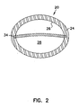
- Figures 1A and 2 shows one embodiment of an implantable device 20 for restricting a body lumen comprising an adjustable, self-sealing element 22, such as an expandable element, having a continuous wall 24.
- the continuous wall 24 includes an inner surface 26 defining a chamber 28.
- the continuous wall 24 is constructed of at least one material that is substantially self-sealing to allow for the adjustable element 22 to be expanded or contracted due to fluid volume introduced into the chamber 28.
- the continuous wall 24 itself is constructed of a self-sealing material.
- the inner surface 26 of the adjustable element 22 has a material that imparts a self-sealing ability to the adjustable element 22 such as crosslinked silicone gel, polyvinylpyrrolidone, or karaya gum for example.
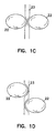
- Figures 1B-D show several embodiments of genitourinary prosthesis implanted in a patient.
- Figure 1B is one embodiment of positioning the adjustable element 22 of the present invention, where one adjustable element 22 is positioned adjacent a urethra 23 of the patient.
- Figure 1C shows two of the adjustable element 22 positioned adjacent the urethra 23, where each of the adjustable element 22 are generally disposed on opposite sides of and in a similar plane perpendicular to the urethra 23.
- FigurelD shows two of the adjustable elements 22 positioned adjacent the urethra 23, where each of the adjustable elements 22 are generally disposed on opposite sides of the urethra 23, with each of the adjustable elements 22 in generally a different plane perpendicular the urethra 23 to create at least two portions of the urethra having a coapted portion and leading to the urethra 23 having a tortuous configuration.
- the adjustable element 22 is placed next to a ureteral orifice.
- the continuous wall 24 is intended and designed to be pierced by hollow non-coring needles on one or more occasions for adjusting the volume of the adjustable element during both the implanting of the adjustable element and during subsequent postoperative adjustment of the adjustable element.
- the continuous wall 24 is constructed of a material that is tear-resistant and biocompatible.
- the material is also substantially self-sealing during and after being pierced by a hollow non-coring needle to maintain fluid volume within the chamber 28 of the adjustable element.
- the adjustable element 22 has two or more continuous walls 24, where the continuous walls 24 are arranged concentrically with one of two or more continuous walls 24 being within another continuous wall 24 (not shown).
- the two or more continuous walls 24 of the present embodiment are separated from each other due to the presence of fluid between the continuous walls 24.
- the chambers created by each of the continuous walls 24 are filled with any combination of fluids described within this detailed description.
- the continuous wall is constructed of a biocompatible resiliently elastomeric polymer or polymer blend of polyurethane, silicone, or the like.
- the continuous walls 24 stretch as the adjustable element 22 expands or contracts to a desired size.
- the continuous wall is constructed of a biocompatible non-resilient polymer or polymer blend of polyethylene, polytetraflouroethylene, polystyrene, or polyesteretherketone (PEEK).
- PEEK polyesteretherketone
- the continuous wall 24 of the adjustable element 22 expand to a predetermined shape.
- the adjustable element is formed into a variety of shapes.
- the outer surface 32 of the continuous wall 24 generally defines a spherical shape.
- the outer surface 32 of the continuous wall 24 generally defines an elongate body having semi-spherical end portions.
- a adjustable element 22 being constructed of a biocompatible resiliently elastomeric polymer or polymer blend typically retains the same general cross-sectional shape deflated as when inflated.
- the deflated adjustable element 22 typically has a configuration in which the continuous wall 24 has a folded structure which as the adjustable element 22 is inflated changes to take on a preformed cross-sectional shape and size and/or diameter.
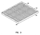
- the continuous wall 24 further includes one or more reinforcing structures 30 positioned between the inner surface 26 and an outer surface 32 of the continuous wall 24.
- the one or more reinforcing structures 30 are designed to support the structural integrity of the continuous wall 24, helping to provide the substantially self-sealing nature of the adjustable element 22, and to assist in retaining particles within the chamber 28 of the adjustable element 22.
- the one or more reinforcing structures 30 are fibers constructed from the group comprising one or more of polyester, nylon, polypropylene, polytetrafluoroethylene (such as TEFLON) or other polymers having a high durometer measure or high modulus constitute the reinforcing structures.
- the fibers of the one or more reinforcing structures 30 form a mesh, such as when woven into a support structure that is positioned between the inner surface 26 and the outer surface 32 of the continuous wall 24.
- the fibers of the one or more reinforcing structures 30 are less elastic than the continuous wall 24, and the woven support structure has a loose weave configuration to allow for the support structure to expand or contract with the expansion and contraction of the continuous wall 24 of the adjustable element 22.
- the fibers of the one or more reinforcing structures 30 are substantially non-elastic and are arranged in a woven configuration, where the fibers have a kinked structure that allows them to expand or contract with the expansion and contraction of the continuous wall 24 of the adjustable element 22.
- the one or more reinforcing structures 30 provide the adjustable element 22 with reinforced structural integrity and an increased ability to retain infused particles within the chamber 28 of the adjustable element 22.
- the fibers of the one or more reinforcing structures 30 woven into the support structure provide a "rip-stop" function.
- the woven support structure allows for rip-stop protection from tears in the continuous wall 24 due to insertion and removal of hollow non-coring needles through the continuous wall 24.
- the woven support structure prevents the migration of particle from the chamber 28, where the particles are used to inflate the adjustable element 22.
- the particles are prevented from migrating out of the chamber 28 due to the tightness of the weave of the support structure.
- particulate matter is suitable for infusing into the chamber 28 of the adjustable element 22.
- the particulate matter is typically suspended in a carrier fluid, or lubricious fluid, however, this is not necessary.
- suitable particulate matter shapes include collapsible hollow spheres or those having multiple projecting arms or structures from a central axis.
- the structure of the particulate matter has a larger diameter than both the inner diameter of the hollow non-coring needle and the opening in the woven structure of the reinforcing structure 30.
- the surface of the particulate matter is physically distorted to allow it to pass through the inner diameter of the hollow non-coring needle, such as the hollow spheres collapsing or the projecting arms bending. Once the particulate matter has passed through the hollow non-coring needle, the particulate matter expands back to a size greater than the hole created by the needle, thus making the device self sealing.
- the particulate matter is an elongate body, such as a tubular elongate structure, such that the particulate matter can pass longitudinally through the hollow non-coring needle, but once inside the adjustable element 22 their random orientation would essentially prevent them from passing back through any needle hole created by the hollow non-coring needle.
- the inner diameter of the hollow non-coring needle is sufficient to pass the particulate matter, however the structure of the particulate matter has a larger diameter than the openings in the woven structure of the reinforcing structure 30.
- inserting the hollow non-coring needle distorts the mesh of the woven structure of the reinforcing structure 30 to allow the hollow non-coring needle to pass through the continuous wall 24 and into the chamber 28.
- the particle is made of a hydrophillic material such as polyvinylpyrrolidone, polyethylene glycol, carboxy methyl cellulose, hyaluronic acid, or the like, which expands once inside the adjustable element 22 due to the absorption of liquid that is either delivered with the particles or passes through at least a portion of the continuous wall 24 of the adjustable element 22.
- a hydrophillic material such as polyvinylpyrrolidone, polyethylene glycol, carboxy methyl cellulose, hyaluronic acid, or the like, which expands once inside the adjustable element 22 due to the absorption of liquid that is either delivered with the particles or passes through at least a portion of the continuous wall 24 of the adjustable element 22.
- a detectable marker 34 is embedded in the continuous wall 24 of the adjustable element 22.
- the detectable marker 34 allows the adjustable element 22 to be located and its shape to be visualized within the tissues of a patient using any number of visualization techniques which employ electromagnetic energy as a means of locating objects within the body.
- the detectable marker is constructed of tantalum and the visualization techniques used to visualize the adjustable element 22 are x-ray or fluoroscopy as are known in the art.
- the one or more reinforcing structures 30 are labelled with tantalum to allow the adjustable element 22 to be visualized using x-ray, fluoroscopy or other visualization techniques as are known in the art.
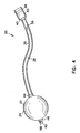
- an alternative embodiment of the implantable device 20 further includes a tubular elongate body 36, such as a conduit, where the tubular elongate body 36 has a peripheral surface 38, a proximal end 40 and a distal end 42.
- the adjustable element 22 has at least one opening through the continuous wall 24 to which the peripheral surface 38 is connected to and sealed to the adjustable element 22.
- the adjustable element 22 includes an expandable element.
- the tubular elongate body 36 is inserted through the first opening 44 and the second opening 46 such that the distal end 42 of the elongate body 36 partially extends beyond the outer surface 32 of the adjustable element 22.
- the peripheral surface 38 is then sealed to the walls creating the first opening 44 and the second opening 46.
- the peripheral surface 38 is sealed to the openings using a chemical or polymer adhesive, such as silicone.
- the peripheral surface 38 is sealed to the openings using sonic welding techniques as are known in the art.
- the adjustable element is an expandable element.
- the tubular elongate body 36 further includes a first interior passageway 48 extending longitudinally in the tubular elongate body 36 from a first port 50 at the proximal end 40 to a second port 52 in fluid communication with the chamber 28 of the implantable device for adjustably expanding or contracting the adjustable element 22 by applied fluid volume introduced through the first port 50.
- the tubular elongate body 36 further includes a second interior passageway 54 extending longitudinally in the tubular elongate body 36 from a proximal opening 56 through the peripheral surface 38 positioned between the proximal end 40 and the distal end 42 to a distal opening 58 through the distal end 42 of the tubular elongate body 36.
- the second interior passageway 54 is of sufficient diameter to receive and guide an elongate probe member for the insertion of the implantable device 20 into a human body.
- the elongate probe member is removably attached at the distal end 42 and passes outside the adjustable element 22 and along side the elongate body 36 to allow placement of the device without the need for the second interior passageway 54.
- the implantable device 20 further includes a rear port element 60 coupled to the proximal end 40 of the tubular elongate body 36.
- the rear port element 60 is coupled to the proximal end 40 of the elongate body 36 using chemical adhesives, or alternatively, using sonic welding techniques as are known in the art.
- the rear port element 60 and proximal end 40 of the elongate body 36 are formed together as one piece in a polymer extrusion process or polymer casting process as are known in the art.
- the rear port element 60 and the elongate body 36 are formed of a biocompatable material such as silicone or polyurethane elastomer.
- the rear port element 60 includes a cavity 62, where the cavity 62 is in fluid communication with the first port 50 of the elongate body 36.
- the rear port element 60 also includes an elastic septum 64 through which the cavity 62 is accessed.
- the elastic septum 64 is retained in the rear port element 60 by a clamp ring 66 located around the rear port element 60.
- the clamp ring 66 is made of a biocompatible material, such as, for example, titanium.
- the elastic septum 64 is made of a biocompatible material, such as, for example, silicone or polyurethane.
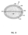
- the implantable device 20 comprises an adjustable element 100 having a continuous wall 102, including an inner surface 104 and an outer surface 106, where the inner surface 104 defines a chamber 108.
- the continuous wall 102 also has at least a portion of the continuous wall that is constructed of a porous polymer structure that allows the movement of water between the outer surface 106 and the inner surface 104.
- a hydrophilic polymer 110 is substantially encapsulated in the chamber 108, where the hydrophilic polymer 110 absorbs water. As the hydrophilic polymer 110 absorbs water, it causes the chamber 108 to expand, thus enlarging the adjustable element 100.
- the continuous wall 102 is intended and designed to be pierced by hollow non-coring needles on one or more occasions for adjusting the volume of the adjustable element during both the implanting of the adjustable element and during subsequent postoperative adjustment of the adjustable element.
- the continuous wall 102 is constructed of a material that is substantially self-sealing during and after being pierced by a hollow non-coring needle to maintain fluid volume within the chamber 108 of the adjustable element, and the adjustable element expands or contracts by introducing or removing the hydrophilic polymer from the chamber.
- the continuous wall 102 further includes one or more reinforcing structures 120 positioned between the inner surface 104 and the outer surface 106 of the continuous wall 102.
- the one or more reinforcing structures 120 are arranged in a mesh, including fibers in a woven structure.
- the fibers are constructed from the group comprising one or more of polyester, nylon, polypropylene, polytetrafluoroethylene (such as TEFLON) or other polymers having a high durometer measure or high modulus constitute the reinforcing structures.
- the fibers of the one or more reinforcing structures 120 are woven into a support structure that is positioned between the inner surface 104 and the outer surface 106 of the continuous wall 102. In an additional embodiment, the fibers of the one or more reinforcing structures 120 are less elastic than the continuous wall 102.
- the woven support structure in one embodiment, has a loose weave configuration to allow for the support structure to expand or contract with the expansion and contraction of the continuous wall 102 of the adjustable element 100.
- the fibers of the one or more reinforcing structures 120 are substantially non-elastic and are arranged in a woven or mesh configuration, where the fibers have a kinked structure that allows them to expand or contract with the expansion and contraction of the continuous wall 102 of the adjustable element 100.
- the one or more reinforcing structures 120 provide the adjustable element 100 with reinforced structural integrity and an increased ability to retain particles within the chamber 108 of the adjustable element 100.
- the fibers of the one or more reinforcing structures 120 woven into the support structure provide a "rip-stop" function.
- the woven support structure allows for rip-stop protection from tears in the continuous wall 102 due to insertion and removal of hollow non-coring needles through the continuous wall 102.
- the support structure prevents the migration of particle from the chamber 108, where the particles are used to inflate the adjustable element 100.
- the particles are prevented from migrating out of the chamber 108 due to the size of the mesh of the support structure.
- a detectable marker 122 is embedded in the continuous wall 102 of the adjustable element 100.
- the detectable marker 122 allows the adjustable element 100 to be located and its shape to be visualized within the tissues of a patient using any number of visualization techniques which employ electromagnetic energy as a means of locating objects within the body.
- the detectable marker is constructed of tantalum and the visualization techniques used to visualize the adjustable element 100 are x-ray or fluoroscopy as are known in the art.
- the one or more reinforcing structures 120 are labeled with tantalum to allow the adjustable element 100 to be visualized using x-ray, fluoroscopy or other visualization techniques as are known in the art.
- the hydrophilic material used within the chamber 108 of the adjustable element 100 is selected from a group comprising one or more of polyvinylpyrrolidone, polyethylene glycol, carboxy methyl cellulose, or hyaluronic acid.
- the hydrophilic polymer has a particulate structure, where the hydrophilic polymer takes the form of discrete, individual polymeric units. Additionally, the particulate structure of the hydrophilic polymer has an average diameter that is greater than an average diameter of pores of the porous polymer structure.
- the porous polymer structure of the continuous wall 102 has openings that are less than or equal to 200 micrometers.
- the continuous wall 102 is constructed of a biocompatible resiliently elastomeric polymer or polymer blend of polyurethane, silicone, or the like. In this embodiment, the continuous wall 102 stretches as the adjustable element 100 expands or contracts to a desired size. In an alternative embodiment, the continuous wall 102 is constructed of a biocompatible non-resilient polymer or polymer blend of polyethylene, polyesterterethalate, or high modulus polystyrene, or polyesteretherketone. In this embodiment, the continuous wall 102 of the adjustable element 100 expand to a predetermined shape.
- the adjustable element 100 is formed into a variety of shapes. In one embodiment, the outer surface 106 of the continuous wall 102 generally defines a spherical shape.
- the outer surface 106 of the continuous wall 102 generally defines an elongate body having semi-spherical end portions.
- an adjustable element 102 being constructed of a biocompatible resiliently elastomeric polymer or polymer blend typically retains the same general cross-sectional shape deflated as when inflated.
- the deflated adjustable element 102 typically has a configuration in which the continuous wall 102 has a folded structure which as the adjustable element 100 is inflated changes to take on a preformed cross-sectional shape and size and/or diameter.
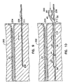
- FIG. 9 there is shown an embodiment of the method of implanting one embodiment of the implantable device assembly 200 of the present invention for restricting a body lumen in a patient.
- the implantable device assembly 200 is adapted to be surgically implanted into body tissue 202 of a patient adjacent to a body lumen for coapting the body lumen.
- the implantable device assembly 200 comprises an elongate probe member adapted for being inserted as a guide member into body tissue 202 to locate a portion of the obturator adjacent the body lumen to be restricted.
- the elongate probe member is an obturator 206 having a cutting end 208.
- a physician after locating the body lumen such as the urethra 23 of a patient, first makes a small incision in skin of the patient 211 and inserts the obturator 206, or elongate probe member, in the body tissue to a desired location adjacent the urethra 23. This procedure is usually carried out under a local anaesthetic with visual guidance, for instance by cystoscopy or fluoroscopy by the physician.
- the obturator 206 is of sufficient strength and rigidity to allow its insertion into the tissue 202 of the patient adjacent and parallel with the urethra 23.
- an implantable medical device 210 adapted for being surgically implanted into the tissue 202 adjacent to the body lumen, is then positioned onto the obturator 206 and advance into the tissue 202 of the patient.
- the obturator 206 is inserted near the meatus urinarius 204 and advance through the periurethral tissue adjacent the urethra 23.
- a detent or mark is provided on the obturator 206 which when aligned with a feature on the implantable medical device 210, such as a rear port element 60, ensures that an implantable medical device 210 is appropriately placed at the correct depth in the patient's body tissue.
- the elongate body 36 of the implantable medical device 210 is available having a variety of lengths to accommodate the patient's anatomic structure so as to facilitate placement of the elastic septum on the rear port element 60 near the patient's skin.
- the elongate body 36 effective length could be made adjustable by it having a helical shape similar to that of a coiled spring.
- the implantable medical device of the present invention relates to use in female patients.
- a physician will initially make a small incision at either side of the meatus, i. e. opening of the female urethra.
- This incision(s) permits an obturator, or a delivery probe member, to be inserted into the body tissue alongside of the urethra so as to define the path of later entry for the implantable device.
- delivery of the device along the guide probe is made on either one or two opposite sides of the urethra, one placement at a time.
- the implanted device with the expandable membrane element directed to each location is left in place, with access for adjustment of the membrane size being available through a remote elastic septum in the rear port away from the expandable membrane and located immediately under the skin of the patient.
- Figure 10 shows one embodiment of the implantable medical device 210, where the implantable medical device 210 includes an adjustable element 22, a tubular elongate body 36, and a rear port element 60.
- the adjustable element 22 has a continuous wall, including an inner surface defining a chamber.
- the tubular elongate body 36 has a peripheral surface 38, a proximal end 40 and a distal end 44, where the peripheral surface is connected to and sealed to the adjustable element 22.
- the tubular elongate body includes a first interior passageway and a second interior passageway, the first interior passageway extending longitudinally in the tubular elongate body from a first port at the proximal end to a second port in fluid communication with the chamber of the implantable device for adjustably expanding or contracting the adjustable element 22 by applied fluid volume introduced through the first port.
- the second interior passageway also extends longitudinally in the tubular elongate body 36 from a proximal opening 56 through the peripheral surface 38 positioned between the proximal end 40 and the distal end 44 to a distal opening 58 through the distal end of the tubular elongate body 42.
- the second interior passageway being of sufficient diameter to receive and guide the obturator 206, or elongate probe member, for the insertion of the implantable device into the patient's body.
- the rear port element 60 of the implantable medical device 210 is coupled to the proximal end 40 of the tubular elongate body 36, where the rear port element includes a cavity in fluid communication with the first port of the first interior passageway.
- the portion of the obturator 206 extending from the patient's body is inserted into the distal opening 58 of the second interior passageway.
- the implantable medical device 210 is then advance or moved along or over the obturator 206 to position the adjustable element 22 adjacent the body lumen to be restricted and to position the rear port element subcutaneously.
- the adjustable element 22 is positioned adjacent a urethra.
- two or more of the implantable medical devices 220 are implanted within the body tissue adjacent a urethra.
- the obturator 206 is then withdrawn from the tissue of the patient by pulling the obturator 206 through the proximal opening 56 of the second interior passageway, leaving the implantable medical device 210 in position.
- the implantable medical device 210 implanted in the tissue of a patient for restricting a body lumen.
- the body lumen is the urethra 23 and the implantable medical device 210 has been implanted in the periurethral tissue of the patient.
- the implantable medical device 210 After the implantable medical device 210 has been advanced over the obturator 206, or elongate probe member, so that the contracted adjustable element 22 is in the desired position adjacent to the urethra 23, the urethra 23 is restricted to a desired degree by piercing the elastic septum with a needle of a syringe and injecting a flowable material through the first interior passageway into the adjustable element 22.
- the physician may determine the desired degree of restriction of urethra 23 by means such as infusing fluid through the urethra 23 past the restriction and measuring the back pressure.
- the source of flowable material is usually a syringe 220 with a hollow non-coring needle 222 used to pierce the elastic septum, however alternate fluid containers with means for making a reversible connection to implantable medical device 210 could be used.
- the flowable material may be, for example, a saline solution, a flowable gel, or a slurry of particles in a liquid carrier. It may be advantageous to make the flowable material radiopaque so that the degree of membrane inflation may be viewed by x-ray.
- An alternative method of delivery of the implantable medical device 210 could be to first withdraw obturator 206, or elongate probe member, from the body tissue and then inflate adjustable element 22.
- a further alternative would be to first place the implantable medical device 210 over the obturator 206, or elongate probe member, outside the body and then insert them both into the body tissue as a unit. To facilitate this latter procedure, it may be desirable that there be some friction between the obturator 206, or elongate probe member, and the second interior passageway.
- the implantable medical device 210 is injected with a flowable material from the syringe 220. Once filling of the adjustable element 22 is complete, the obturator 206, or elongate probe member, is withdrawn from the implantable medical device 210 leaving the adjustable implantable medical device in the body tissue. Then the skin incision is closed over the rear port element 60 by means such as a suture 230 as shown in Figure 12 .
- the presence of the port located near the surface of the patient's skin affords the additional advantage of allowing the device to be easily removed through a small incision in the skin if, for instance, it was to become infected or malfunction, whereas the prior art devices would require major surgery.
- the presence of the elongate body and the rear port of the implantable device left in the device delivery tract will serve to prevent backward migration of the expandable element along the tract, a problem which has been noted with prior art devices.
- twists or coils in the implanted device elongate body may permit the body tissue to grow around it and further anchor the implantable device in the patient's body.
- one feature of this invention relates to the adjustability of the adjustable element 22 postoperatively.
- This adjustability is effected because the elastic septum is located remote from the adjustable element 22 but near and under the patient's skin.
- the rear port element 60 and the elastic septum are located by, for instance, manual palpation of the skin region and the needle of the syringe is inserted through the skin and septum so as to add or remove material from the adjustable element 22, thus increasing or decreasing the restriction of the body lumen.
- the adjustable element 22 implanted adjacent a body lumen.
- the adjustable element 22 is shown in an expanded state, such that it increases both localized tissue volume and passive occlusive pressure upon the body lumen.
- the body lumen is the urethra 23 of a patient, and the patient's incontinence is treated by positioning one or more of the adjustable elements 22 of the implantable medical devices 210 adjacent the urethra 23 so as to allow the physician to adjust liquid flow resistance in the urethra 23.
- two of the devices are implanted on opposite sides of the urethra so as to effect a balanced urethral coaptation and resistance.
- a post-operative membrane size adjustment is available to reduce the patient's bladder pressure during voiding and maintain intravesical pressure within normal limits.
- two individual devices with individual septa are implanted on opposite sides of the urethra.
- the device may be so configured to have one septum serve both expandable membrane elements. Therefore, the present invention allows a more normal voiding process while maintaining continence in the patient.
- This post-operative adjustment feature promotes normal voiding patterns for the patient, and appropriate vesicourethral pressure during voiding.
- post-operative adjustment is done in a semi vertical or horizontal position with the bladder full after anesthesia is resolved and edema is minimal.
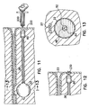
- FIGs 14 and 15 there is shown embodiments of postoperatively adjusting an implanted adjustable element 22.
- the adjustable element 22 having been implanted adjacent a body lumen within a patient, is first located within the tissues of the patient. In one embodiment, locating the adjustable element 22 is accomplished using fluoroscopy, x-ray, or ultrasound visualization techniques as are known in the art. Once the adjustable element has been located within the tissue of the patient, the physician then proceeds to establish fluid communication with the adjustable element 22.
- one adjustable element 22 having generally a spherical configuration is shown positioned adjacent a body lumen, such as a urethra or a ureteral orifice, of a patient.
- Figure 15 shows an additional embodiment where two adjustable elements 22 each having a configuration that is generally an elongate body having semi-spherical end portions.
- fluid communication is established with the adjustable element by first inserting a catheter structure 300 into the urethra of the patient.
- the catheter structure 300 has an elongate body 302 proximal end 304 and a distal end 306.
- the catheter structure 300 includes a fluid passageway extending longitudinally within the catheter structure 300 from an inlet port 308 at the proximal end 304 to a outlet port 310 at the distal end 306.
- a hollow non-coring needle 312 is coupled to the outlet port 310.
- the fluid passageway housed within the elongate body 302 of the catheter structure 300 moves longitudinally within the elongate body 302 to allow the hollow non-coring needle 312 coupled to the outlet port 310 to, in one position, extend beyond the distal end 306 of the elongate body 302, and in another position to be housed completely within the elongate body 302 of the catheter structure 300.
- the path of the hollow non-coring needle 312 as it is extended beyond the distal end 306 of the catheter structure 300 deflects away from a plane that is generally parallel with the longitudinal axis of the elongate body 302 of the catheter structure 300. In one embodiment, this allows the hollow non-coring needle 312 to penetrate through the urethral tissue and into the continuous wall of the adjustable element 22. The hollow non-coring needle 312 is then advance into the chamber of the adjustable element 22 at which point the physician adjusts the volume of the adjustable element 22. In one embodiment, the volume of the adjustable element is adjusted by passing fluid and/or particles through the hollow non-coring needle to adjustably contract or expand the adjustable element 22 due to fluid volume introduced into the chamber.
- Figure 15 shows an alternative embodiment for adjusting the adjustable element 22, where the catheter structure 300 is first inserted through the tissues of the patient. The distal end of the catheter structure 300 is then aligned with the outside surface of the adjustable element 22 and the hollow non-coring needle 312 is advanced through the continuous wall of the adjustable element and into the chamber to allow the adjustable element to be either expanded or contracted by passing fluid, particles and/or hydrophilic polymer through the hollow non-coring needle 312 as previously described.
- the elongate body 302 of the catheter structure 300 acts as a needle stop to limit the depth to which the needle is allow to penetrate the implanted adjustable element 22.
- the outer surface 32 of the adjustable element is secured to the catheter structure 300 during the insertion of the hollow non-coring needle 312 into the adjustable element 22.
- a suction passageway extends longitudinally within the elongate body 302 to allow the distal end 306 of the catheter structure 300 to be secured to the outer surface 32 of the adjustable element 22 by a negative or vacuum pressure applied through the suction passageway.
Abstract
Description
- The invention relates generally to implantable medical devices and in particular to implantable medical devices for treating urinary incontinence.
- Various implantable devices, such as distensible medical devices, are known in which the distensible medical devices are implanted into the tissue of a human to treat urinary incontinence. These devices have typically relied upon restricting or constricting the urethra of the patient to maintain continence.
-
U.S. Patent 4,733,393 to Haber et al. is an attempt at such a proposed device.U.S. Patent 4,733,393 relates to a hypodermically implantable genitourinary prosthesis which provides an extensible, inflatable tissue expanding membrane to be located in proximal urethral tissue to add bulk to these tissues for overcoming urinary incontinence by localized increase in tissue volume. -
U.S. Patent 4,802,479 to Haber et al. is an attempt at an instrument for dispensing and delivering material to an inflatable membrane of a genitourinary prosthesis within the tissues of a patient for overcoming urinary incontinence.U.S. Patent 4,832,680 to Haber et al. relates to an apparatus for hypodermically implanting a genitourinary prosthesis comprising an extensible containment membrane for retaining a fluid or particulate matter which is injected from an external source. -
U.S. Patent 5,304,123 to Atala et al. relates to a detachable membrane catheter incorporated into an endoscopic instrument for implantation into the suburethral region of a patient. Also,U.S. Patent 5,411,475 to Atala et al. discusses a directly visualized method for deploying a detachable membrane at a target site in vivo. - Once inflated, these devices maintain pressure on the urethra of the patient in an attempt to assist with continence. However, these devices are prone to being under or over inflated at time of implant, leading to undesirable postoperative results. For example, if the devices are overinflated it may cause the urethra to be restricted too tightly, and the patient is at risk for retention, a condition where the patient cannot pass urine. Such a condition could lead to kidney damage, necessitating major corrective surgery or at minimum use of self-catheterization to empty the bladder on a regular basis thus increasing the risk of urinary tract infection.
- Furthermore, once these devices have been implanted within the patient, the only means of removing them in the event of a postoperative problem or device malfunction is through major surgery. Additionally, once the device has been implanted into the patient there is the possibility of the device migrating back along the pathway created during its insertion, a problem which has been noted with prior art devices. Thus, an important medical need exists for an improved implantable device for treating urinary incontinence.
- The present invention provides an implantable device and a method for its use in restricting a body lumen. In one embodiment, the body lumen is a urethra, where the implantable device is used to coapt the urethra to assist the patient in urinary continence. The implantable medical device has the advantage of being adjustable both at the time of implantation and postoperatively. This postoperative adjustability of the implantable medical device allows a physician to regulate the amount of pressure applied to the urethra to ensure continence of the patient and to minimize iatrogenic effects.
- In one embodiment of the invention, a patient's incontinence is treated by positioning one or more of the implantable devices adjacent to at least one side of a patient's urethra so as to adjust liquid flow resistance in the urethra.
- This is accomplished by using the implantable devices to coapt the patient's urethra so as to maintain a transverse cleft or slit structure of the collapsed urethra and thereby provide sufficient flow resistance to ensure continence, while still allowing the patient to consciously discharge urine when necessary.
- The device according to one embodiment of the invention is intended to work immediately adjacent to the urethral wall of a patient to create an increase in urethral coaptation and flow resistance. In one embodiment, this increase in urethral coaptation and flow resistance is due to the displacement of body tissue adjacent to the body lumen. However, in the prior art devices any tissue change which may occur postoperatively such as a reduction in tissue edema associated with the procedure may cause a reduction in clinical effect because of the reduced coaptation and resistance after the swelling has subsided.
- In one embodiment, the implantable device for treating urinary incontinence comprises an adjustable element having a continuous wall or membrane, where the wall includes an inner surface defining a chamber. The continuous wall is constructed of at least one material that is substantially self-sealing, and therefore, is able to withstand multiple punctures, for example from non-coring hypodermic needles, during postoperative adjustments of the adjustable element.
- In one embodiment, the continuous wall is constructed of a biocompatible resiliently elastomeric polymer or polymer blend of polyurethane, silicone, or the like. In an additional embodiment, the continuous wall of the adjustable element has an outer surface generally defining a sphere. In yet another embodiment, the continuous wall has an outer surface generally defining an elongate body having semi-spherical end portions.
- During the postoperative adjustments, the adjustable element is expanded or contracted (i. e., the volume of the adjustable element is increased or decreased) due to fluid volume introduced into the chamber. In one embodiment, fluid volume is introduced into the chamber through a hollow non-coring needle, such as a hypodermic needle, inserted through the wall of the adjustable element. The self-sealing ability of the wall allows for such adjustments by needles during one or more postoperative occasions without compromising the pressure retaining ability of the wall of the adjustable element.
- In an additional embodiment, the implantable device includes one or more reinforcing structures positioned between the inner surface and an outer surface of the continuous wall. In one embodiment, woven or layered fibers of polyester, nylon, polypropylene, polytetrafluoroethylene (such as TEFLON) or other polymers having a high durometer measure or high modulus constitute the reinforcing structures. The reinforcing structures help to maintain structural integrity and the shape of the adjustable element during the initial inflation and any postoperative adjustments made thereafter.
- In an additional embodiment, the continuous wall of the adjustable element has a porous polymer structure that allows the movement of water between the outer surface and the inner surface. A hydrophilic polymer is substantially encapsulated in the chamber, where the hydrophilic polymer absorbs water to expand the implantable device. Once implanted within a patient, the volume of the adjustable element is altered (i. e., expanded or contracted) during implantation and/or postoperatively by introducing or removing the hydrophilic polymer from the chamber. In one embodiment, the hydrophilic polymer is hyaluronic acid, polyvinylpyrrolidone, polyethylene glycol, or carboxy methyl cellulose.
- In an additional embodiment, the implantable medical device includes a tubular elongate body, such as a conduit, connected to and sealed to the adjustable element. The tubular elongate body includes a first interior passageway extending longitudinally in the tubular elongate body from a first port at the proximal end to a second port in fluid communication with the chamber of the implantable device for adjustably expanding or contracting the adjustable element by applied fluid volume introduced through the first port.
- Expansion of the adjustable element is accomplished by delivering a fluid material into the first port of the implantable device remote from the adjustable element, but near the patient's skin, thus enabling post-operative adjustment with minimal surgical invasiveness.
- The tubular elongate body further includes a second interior passageway extending longitudinally in the tubular elongate body from a proximal opening through the peripheral surface positioned between the proximal and the distal end to a distal opening through the distal end of the tubular elongate body. This second interior passageway is of sufficient diameter to receive an elongate probe member adapted for delivery of the implantable medical device to the desired site in the body tissue of a patient. In one embodiment, the elongate probe member is a solid stylet. In one embodiment, the elongate probe member is an obturator. Alternatively, the elongate probe member includes a flexible guidewire which has been initially delivered into the body tissue through a separate hollow stiff probe that has been inserted to the desired location in the body tissue.
- This embodiment of the implantable device also includes a rear port element coupled to the proximal end of the tubular elongate body. The rear port element including a cavity in fluid communication with the first port of the first interior passageway. An elastic septum is included on the rear port element, and is retained in the rear port element by a clamp ring located around the rear port element.
- An improvement provided by one embodiment of the present invention resides in the ability to access the implanted rear port element located close to the surface of the patient's skin to adjustably restrict the urethra. This is accomplished by controlling the volume of a fluid, such as a flowable material, in the adjustable element after it has been implanted in the patient. Suitable flowable materials for introduction into the expandable membrane include a saline liquid, a flowable gel, or a slurry of small particles such as silicone in a fluid carrier. Moreover, the flowable material may be made radiopaque to facilitate fluoroscopic visualization for postoperative inspection.
- The post implantation, or postoperative, urethral restriction is realized by the adjustable element acting on tissue adjacent to the walls of the urethral lumen and forcefully closing the urethral lumen. Voiding of urine from the bladder only occurs when the intravesical pressure overcomes the resistance established by the adjustable element.
- An important feature of the implantable device of the present invention relates to the adjustable element or membrane which is accessible for subsequent adjustment in volume through the rear port element located under a patient's skin, remotely from the adjustable element. Another important feature of the present invention over the prior art devices is the convenient in vivo postoperative adjustability of both pressure and size of the adjustable element.
- In the drawings, where like numerals describe like components throughout the several views:
-
Figure 1 (A-D) is a schematic view of an adjustable element according to one embodiment of the present invention; -
Figure 2 is a schematic cross-sectional view of the adjustable element ofFigure 1 ; -
Figure 3 is one embodiment of reinforcing structures within the continuous wall of the adjustable element; -
Figure 4 is one embodiment of an implantable device according to the present invention; -
Figure 5 is a longitudinal cross-sectional view of the implantable device ofFigure 4 ; -
Figure 6 is a cross-sectional view taken along line 6-6 ofFigure 5 ; -
Figure 7 is a schematic view of an adjustable element according to one embodiment of the present invention; -
Figure 8 is a schematic cross-sectional view of the adjustable element ofFigure 7 ; -
Figure 9 is one embodiment of an elongate probe member inserted into body tissue to an implant location adjacent a body lumen of a patient prior to insertion of the implantable device; -
Figure 10 is one embodiment of the implantable device placed over an elongate probe member and partially advanced to the desired location with the adjustable element being deflated; -
Figure 11 is one embodiment of the implantable medical device implanted within the body tissue with the adjustable element expanded to cause the adjustable restriction of the body lumen; -
Figure 12 is a partial view of one embodiment of the implantable medical device implanted within the body tissue; -
Figure 13 is a cross-sectional view taken along line 13-13 ofFigure 11 ; -
Figure 14 is one embodiment of adjusting an implanted adjustable element; and -
Figure 15 is one embodiment of adjusting an implanted adjustable element. - In the following detailed description, reference is made to the accompanying drawings which form a part hereof and in which is shown by way of illustration specific embodiments in which the invention may be practiced.
- These embodiments are described in sufficient detail to enable those skilled in the art to practice and use the invention, and it is to be understood that other embodiments may be utilized and that logical, and structural changes may be made without departing from the spirit and scope of the present invention. The following detailed description is, therefore, not to be taken in a limiting sense and the scope of the present invention is defined by the appended claims and their equivalents.
- In one embodiment, the present invention provides an adjustable implantable device which restricts urine from involuntarily escaping from the bladder, thus establishing continence for the patient. This adjustable component can be done in a post-operative manner once the patient has resumed daily activity via an evaluation to determine what activities cause bladder stress and observable incontinence.
- In
Figures 1 (A-D) and 2 of the drawings, there is shown animplantable device 20 for restricting a body lumen. In one embodiment, theimplantable device 20 is for treating ureteral reflux of a patient by implanting at least one of the implantable devices adjacent one or both ureteral orifices. In an alternative embodiment, theimplantable device 20 is for treating urinary incontinence by implanting at least one of the implantable devices adjacent the urethra. - Implantable devices designed for treating urinary incontinence are typically referred to as a genitourinary prosthesis. Many designs for genitourinary prosthesis have been proposed. In one such proposed embodiment, genitourinary prosthesis are comprised of elastomeric, elliptoidally or spherically-shaped containment membranes which have an interior chamber designed to receive a measured supply of fluid to inflate the prosthesis. One such description of a genitourinary prosthesis is also provided in a co-pending
U.S. Patent Application Serial No. 08/873,444 , entitled "Implantable Device and - Method for Adjustably Restricting a Body Lumen" filed June 12, 1997, by Burton et al.
- In one embodiment, the present invention provides an implantable device for adjustably restricting a body lumen, and is suitable for treating both male and female patients suffering from stress incontinence. In treating urinary incontinence, the prosthesis are delivered within the body to a location that is typically within the periurethral tissue and adjacent to the urethra to enable a patient to overcome urinary incontinence by means of increasing both localized tissue volume and passive occlusive pressure upon the urethral mucosa.
- The prosthesis may be mounted on a hollow non-coring needle, such as a hypodermic needle, which is releasably connected to a fluid source, such as a syringe element. In order to facilitate inserting the prosthesis into position, the prosthesis is housed within a tubular body, such as a trocar tube, where the tubular body is designed to penetrate the tissues of the patient, thus allowing the proper placement of the prothesis. Alternatively, the prosthesis could be mounted at or on a distal end of a trocar tube to allow for delivery of the prosthesis within the patient.
- Once the prosthesis has been positioned within the body, it is inflated by infusing a measured supply of fluid volume, including fluid volume having particulate matter into the interior of the membrane of the prosthesis.
- Fluids suitable for infusing into the prosthesis include, but are not limited to, sterile saline solutions, polymer gels such as silicone gels or hydrogels of polyvinylpyrrolidone, polyethylene glycol, or carboxy methyl cellulose for example, high viscosity liquids such as hyaluronic acid, dextran, polyacrylic acid, or polyvinyl alcohol for example, or liquids that coagulate on contact with body fluids. The fluids also include fluids having a variety of particulate matter, and include, but are not limited to particles having a spherical shape, an elongate shape, or particles having a cross sectional star shape. Once the prosthesis has been inflated, the needle is withdrawn from the prosthesis and the tubular body is withdrawn from the body, leaving the inflated prosthesis in position.
-
Figures 1A and2 shows one embodiment of animplantable device 20 for restricting a body lumen comprising an adjustable, self-sealingelement 22, such as an expandable element, having acontinuous wall 24. Thecontinuous wall 24 includes aninner surface 26 defining achamber 28. Furthermore, thecontinuous wall 24 is constructed of at least one material that is substantially self-sealing to allow for theadjustable element 22 to be expanded or contracted due to fluid volume introduced into thechamber 28. In one embodiment, thecontinuous wall 24 itself is constructed of a self-sealing material. In an alternative embodiment, theinner surface 26 of theadjustable element 22 has a material that imparts a self-sealing ability to theadjustable element 22 such as crosslinked silicone gel, polyvinylpyrrolidone, or karaya gum for example. -
Figures 1B-D show several embodiments of genitourinary prosthesis implanted in a patient.Figure 1B is one embodiment of positioning theadjustable element 22 of the present invention, where oneadjustable element 22 is positioned adjacent aurethra 23 of the patient. In an alternative embodiment,Figure 1C shows two of theadjustable element 22 positioned adjacent theurethra 23, where each of theadjustable element 22 are generally disposed on opposite sides of and in a similar plane perpendicular to theurethra 23. In an additional embodiment, FigurelD shows two of theadjustable elements 22 positioned adjacent theurethra 23, where each of theadjustable elements 22 are generally disposed on opposite sides of theurethra 23, with each of theadjustable elements 22 in generally a different plane perpendicular the urethra 23 to create at least two portions of the urethra having a coapted portion and leading to the urethra 23 having a tortuous configuration. In an alternative embodiment, theadjustable element 22 is placed next to a ureteral orifice. - In one embodiment, the
continuous wall 24 is intended and designed to be pierced by hollow non-coring needles on one or more occasions for adjusting the volume of the adjustable element during both the implanting of the adjustable element and during subsequent postoperative adjustment of the adjustable element. As such, thecontinuous wall 24 is constructed of a material that is tear-resistant and biocompatible. In one embodiment, the material is also substantially self-sealing during and after being pierced by a hollow non-coring needle to maintain fluid volume within thechamber 28 of the adjustable element. - In an additional embodiment, the
adjustable element 22 has two or morecontinuous walls 24, where thecontinuous walls 24 are arranged concentrically with one of two or morecontinuous walls 24 being within another continuous wall 24 (not shown). The two or morecontinuous walls 24 of the present embodiment are separated from each other due to the presence of fluid between thecontinuous walls 24. In one embodiment, the chambers created by each of thecontinuous walls 24 are filled with any combination of fluids described within this detailed description. - In one embodiment, the continuous wall is constructed of a biocompatible resiliently elastomeric polymer or polymer blend of polyurethane, silicone, or the like. In this embodiment, the
continuous walls 24 stretch as theadjustable element 22 expands or contracts to a desired size. In an alternative embodiment, the continuous wall is constructed of a biocompatible non-resilient polymer or polymer blend of polyethylene, polytetraflouroethylene, polystyrene, or polyesteretherketone (PEEK). In this embodiment, thecontinuous wall 24 of theadjustable element 22 expand to a predetermined shape. The adjustable element is formed into a variety of shapes. In one embodiment, theouter surface 32 of thecontinuous wall 24 generally defines a spherical shape. In an alternative embodiment, theouter surface 32 of thecontinuous wall 24 generally defines an elongate body having semi-spherical end portions. In one embodiment, aadjustable element 22 being constructed of a biocompatible resiliently elastomeric polymer or polymer blend typically retains the same general cross-sectional shape deflated as when inflated. In an alternative embodiment, when theadjustable element 22 is constructed of a biocompatible non-resilient elastomeric polymer or polymer blend the deflatedadjustable element 22 typically has a configuration in which thecontinuous wall 24 has a folded structure which as theadjustable element 22 is inflated changes to take on a preformed cross-sectional shape and size and/or diameter. - Referring now to
Figure 3 , there is shown an embodiment of a portion of thecontinuous wall 24, where thecontinuous wall 24 further includes one or more reinforcingstructures 30 positioned between theinner surface 26 and anouter surface 32 of thecontinuous wall 24. In one embodiment, the one or more reinforcingstructures 30 are designed to support the structural integrity of thecontinuous wall 24, helping to provide the substantially self-sealing nature of theadjustable element 22, and to assist in retaining particles within thechamber 28 of theadjustable element 22. In one embodiment, the one or more reinforcingstructures 30 are fibers constructed from the group comprising one or more of polyester, nylon, polypropylene, polytetrafluoroethylene (such as TEFLON) or other polymers having a high durometer measure or high modulus constitute the reinforcing structures. - In one embodiment, the fibers of the one or more reinforcing
structures 30 form a mesh, such as when woven into a support structure that is positioned between theinner surface 26 and theouter surface 32 of thecontinuous wall 24. In an additional embodiment, the fibers of the one or more reinforcingstructures 30 are less elastic than thecontinuous wall 24, and the woven support structure has a loose weave configuration to allow for the support structure to expand or contract with the expansion and contraction of thecontinuous wall 24 of theadjustable element 22. - In an alternative embodiment, the fibers of the one or more reinforcing
structures 30 are substantially non-elastic and are arranged in a woven configuration, where the fibers have a kinked structure that allows them to expand or contract with the expansion and contraction of thecontinuous wall 24 of theadjustable element 22. - The one or more reinforcing
structures 30 provide theadjustable element 22 with reinforced structural integrity and an increased ability to retain infused particles within thechamber 28 of theadjustable element 22. In one embodiment, the fibers of the one or more reinforcingstructures 30 woven into the support structure provide a "rip-stop" function. As an example, the woven support structure allows for rip-stop protection from tears in thecontinuous wall 24 due to insertion and removal of hollow non-coring needles through thecontinuous wall 24. In an additional embodiment, the woven support structure prevents the migration of particle from thechamber 28, where the particles are used to inflate theadjustable element 22. In one embodiment, the particles are prevented from migrating out of thechamber 28 due to the tightness of the weave of the support structure. - As previously mentioned, a variety of particulate matter is suitable for infusing into the
chamber 28 of theadjustable element 22. The particulate matter is typically suspended in a carrier fluid, or lubricious fluid, however, this is not necessary. Examples of particulate matter shapes include collapsible hollow spheres or those having multiple projecting arms or structures from a central axis. In one embodiment, the structure of the particulate matter has a larger diameter than both the inner diameter of the hollow non-coring needle and the opening in the woven structure of the reinforcingstructure 30. To inject the particulate matter into thechamber 28 of theadjustable element 22, the surface of the particulate matter is physically distorted to allow it to pass through the inner diameter of the hollow non-coring needle, such as the hollow spheres collapsing or the projecting arms bending. Once the particulate matter has passed through the hollow non-coring needle, the particulate matter expands back to a size greater than the hole created by the needle, thus making the device self sealing. - In an alternative embodiment, the particulate matter is an elongate body, such as a tubular elongate structure, such that the particulate matter can pass longitudinally through the hollow non-coring needle, but once inside the
adjustable element 22 their random orientation would essentially prevent them from passing back through any needle hole created by the hollow non-coring needle. - In an alternative embodiment, the inner diameter of the hollow non-coring needle is sufficient to pass the particulate matter, however the structure of the particulate matter has a larger diameter than the openings in the woven structure of the reinforcing
structure 30. In this embodiment, inserting the hollow non-coring needle distorts the mesh of the woven structure of the reinforcingstructure 30 to allow the hollow non-coring needle to pass through thecontinuous wall 24 and into thechamber 28. - Alternatively, the particle is made of a hydrophillic material such as polyvinylpyrrolidone, polyethylene glycol, carboxy methyl cellulose, hyaluronic acid, or the like, which expands once inside the
adjustable element 22 due to the absorption of liquid that is either delivered with the particles or passes through at least a portion of thecontinuous wall 24 of theadjustable element 22. - In an additional embodiment, a
detectable marker 34 is embedded in thecontinuous wall 24 of theadjustable element 22. Thedetectable marker 34 allows theadjustable element 22 to be located and its shape to be visualized within the tissues of a patient using any number of visualization techniques which employ electromagnetic energy as a means of locating objects within the body. In one embodiment, the detectable marker is constructed of tantalum and the visualization techniques used to visualize theadjustable element 22 are x-ray or fluoroscopy as are known in the art. In an additional embodiment, the one or more reinforcingstructures 30 are labelled with tantalum to allow theadjustable element 22 to be visualized using x-ray, fluoroscopy or other visualization techniques as are known in the art. - Referring now to
Figures 4 ,5, and 6 there is shown an alternative embodiment of theimplantable device 20 further includes a tubularelongate body 36, such as a conduit, where the tubularelongate body 36 has aperipheral surface 38, aproximal end 40 and adistal end 42. Theadjustable element 22 has at least one opening through thecontinuous wall 24 to which theperipheral surface 38 is connected to and sealed to theadjustable element 22. In one embodiment, theadjustable element 22 includes an expandable element. The tubularelongate body 36 is inserted through thefirst opening 44 and thesecond opening 46 such that thedistal end 42 of theelongate body 36 partially extends beyond theouter surface 32 of theadjustable element 22. Theperipheral surface 38 is then sealed to the walls creating thefirst opening 44 and thesecond opening 46. In one embodiment, theperipheral surface 38 is sealed to the openings using a chemical or polymer adhesive, such as silicone. In an alternative embodiment, theperipheral surface 38 is sealed to the openings using sonic welding techniques as are known in the art. In one embodiment, the adjustable element is an expandable element. - The tubular
elongate body 36 further includes a firstinterior passageway 48 extending longitudinally in the tubularelongate body 36 from afirst port 50 at theproximal end 40 to asecond port 52 in fluid communication with thechamber 28 of the implantable device for adjustably expanding or contracting theadjustable element 22 by applied fluid volume introduced through thefirst port 50. - In an additional embodiment, the tubular
elongate body 36 further includes a secondinterior passageway 54 extending longitudinally in the tubularelongate body 36 from aproximal opening 56 through theperipheral surface 38 positioned between theproximal end 40 and thedistal end 42 to adistal opening 58 through thedistal end 42 of the tubularelongate body 36. In one embodiment, the second interior passageway 54-is of sufficient diameter to receive and guide an elongate probe member for the insertion of theimplantable device 20 into a human body. In an alternative embodiment, the elongate probe member is removably attached at thedistal end 42 and passes outside theadjustable element 22 and along side theelongate body 36 to allow placement of the device without the need for the secondinterior passageway 54. - The
implantable device 20 further includes arear port element 60 coupled to theproximal end 40 of the tubularelongate body 36. In one embodiment, therear port element 60 is coupled to theproximal end 40 of theelongate body 36 using chemical adhesives, or alternatively, using sonic welding techniques as are known in the art. In an additional embodiment, therear port element 60 andproximal end 40 of theelongate body 36 are formed together as one piece in a polymer extrusion process or polymer casting process as are known in the art. In one embodiment, therear port element 60 and theelongate body 36 are formed of a biocompatable material such as silicone or polyurethane elastomer. - The
rear port element 60 includes acavity 62, where thecavity 62 is in fluid communication with thefirst port 50 of theelongate body 36. Therear port element 60 also includes anelastic septum 64 through which thecavity 62 is accessed. Theelastic septum 64 is retained in therear port element 60 by aclamp ring 66 located around therear port element 60. In one embodiment, theclamp ring 66 is made of a biocompatible material, such as, for example, titanium. In one embodiment, theelastic septum 64 is made of a biocompatible material, such as, for example, silicone or polyurethane. - Referring now to
Figures 7 and8 , there is shown an alternative embodiment of theimplantable device 20 for treating urinary incontinence or ureteral reflux. Theimplantable device 20 comprises anadjustable element 100 having acontinuous wall 102, including aninner surface 104 and anouter surface 106, where theinner surface 104 defines achamber 108. Thecontinuous wall 102 also has at least a portion of the continuous wall that is constructed of a porous polymer structure that allows the movement of water between theouter surface 106 and theinner surface 104. Ahydrophilic polymer 110 is substantially encapsulated in thechamber 108, where thehydrophilic polymer 110 absorbs water. As thehydrophilic polymer 110 absorbs water, it causes thechamber 108 to expand, thus enlarging theadjustable element 100. - In one embodiment, the
continuous wall 102 is intended and designed to be pierced by hollow non-coring needles on one or more occasions for adjusting the volume of the adjustable element during both the implanting of the adjustable element and during subsequent postoperative adjustment of the adjustable element. As such, thecontinuous wall 102 is constructed of a material that is substantially self-sealing during and after being pierced by a hollow non-coring needle to maintain fluid volume within thechamber 108 of the adjustable element, and the adjustable element expands or contracts by introducing or removing the hydrophilic polymer from the chamber. - Referring now to
Figure 8 , there is shown an embodiment of a portion of thecontinuous wall 102, where thecontinuous wall 102 further includes one or more reinforcingstructures 120 positioned between theinner surface 104 and theouter surface 106 of thecontinuous wall 102. In one embodiment, the one or more reinforcingstructures 120 are arranged in a mesh, including fibers in a woven structure. The fibers are constructed from the group comprising one or more of polyester, nylon, polypropylene, polytetrafluoroethylene (such as TEFLON) or other polymers having a high durometer measure or high modulus constitute the reinforcing structures. - In one embodiment, the fibers of the one or more reinforcing
structures 120 are woven into a support structure that is positioned between theinner surface 104 and theouter surface 106 of thecontinuous wall 102. In an additional embodiment, the fibers of the one or more reinforcingstructures 120 are less elastic than thecontinuous wall 102. The woven support structure, in one embodiment, has a loose weave configuration to allow for the support structure to expand or contract with the expansion and contraction of thecontinuous wall 102 of theadjustable element 100. - In an alternative embodiment, the fibers of the one or more reinforcing
structures 120 are substantially non-elastic and are arranged in a woven or mesh configuration, where the fibers have a kinked structure that allows them to expand or contract with the expansion and contraction of thecontinuous wall 102 of theadjustable element 100. - The one or more reinforcing
structures 120 provide theadjustable element 100 with reinforced structural integrity and an increased ability to retain particles within thechamber 108 of theadjustable element 100. In one embodiment, the fibers of the one or more reinforcingstructures 120 woven into the support structure provide a "rip-stop" function. As an example, the woven support structure allows for rip-stop protection from tears in thecontinuous wall 102 due to insertion and removal of hollow non-coring needles through thecontinuous wall 102. In an additional embodiment, the support structure prevents the migration of particle from thechamber 108, where the particles are used to inflate theadjustable element 100. In one embodiment, the particles are prevented from migrating out of thechamber 108 due to the size of the mesh of the support structure. - In an additional embodiment, a detectable marker 122 is embedded in the
continuous wall 102 of theadjustable element 100. The detectable marker 122 allows theadjustable element 100 to be located and its shape to be visualized within the tissues of a patient using any number of visualization techniques which employ electromagnetic energy as a means of locating objects within the body. In one embodiment, the detectable marker is constructed of tantalum and the visualization techniques used to visualize theadjustable element 100 are x-ray or fluoroscopy as are known in the art. In an additional embodiment, the one or more reinforcingstructures 120 are labeled with tantalum to allow theadjustable element 100 to be visualized using x-ray, fluoroscopy or other visualization techniques as are known in the art. - The hydrophilic material used within the
chamber 108 of theadjustable element 100 is selected from a group comprising one or more of polyvinylpyrrolidone, polyethylene glycol, carboxy methyl cellulose, or hyaluronic acid. In one embodiment, the hydrophilic polymer has a particulate structure, where the hydrophilic polymer takes the form of discrete, individual polymeric units. Additionally, the particulate structure of the hydrophilic polymer has an average diameter that is greater than an average diameter of pores of the porous polymer structure. In an additional embodiment, the porous polymer structure of thecontinuous wall 102 has openings that are less than or equal to 200 micrometers. - In one embodiment, the
continuous wall 102 is constructed of a biocompatible resiliently elastomeric polymer or polymer blend of polyurethane, silicone, or the like. In this embodiment, thecontinuous wall 102 stretches as theadjustable element 100 expands or contracts to a desired size. In an alternative embodiment, thecontinuous wall 102 is constructed of a biocompatible non-resilient polymer or polymer blend of polyethylene, polyesterterethalate, or high modulus polystyrene, or polyesteretherketone. In this embodiment, thecontinuous wall 102 of theadjustable element 100 expand to a predetermined shape. Theadjustable element 100 is formed into a variety of shapes. In one embodiment, theouter surface 106 of thecontinuous wall 102 generally defines a spherical shape. In an alternative embodiment, theouter surface 106 of thecontinuous wall 102 generally defines an elongate body having semi-spherical end portions. In one embodiment, anadjustable element 102 being constructed of a biocompatible resiliently elastomeric polymer or polymer blend typically retains the same general cross-sectional shape deflated as when inflated. In an alternative embodiment, when theadjustable element 102 is constructed of a biocompatible non-resilient elastomeric polymer or polymer blend the deflatedadjustable element 102 typically has a configuration in which thecontinuous wall 102 has a folded structure which as theadjustable element 100 is inflated changes to take on a preformed cross-sectional shape and size and/or diameter. - Referring now to
Figures 9 and 10 , there is shown an embodiment of the method of implanting one embodiment of theimplantable device assembly 200 of the present invention for restricting a body lumen in a patient. Theimplantable device assembly 200 is adapted to be surgically implanted intobody tissue 202 of a patient adjacent to a body lumen for coapting the body lumen. - The
implantable device assembly 200 comprises an elongate probe member adapted for being inserted as a guide member intobody tissue 202 to locate a portion of the obturator adjacent the body lumen to be restricted. In one embodiment, the elongate probe member is anobturator 206 having a cuttingend 208. A physician, after locating the body lumen such as theurethra 23 of a patient, first makes a small incision in skin of thepatient 211 and inserts theobturator 206, or elongate probe member, in the body tissue to a desired location adjacent theurethra 23. This procedure is usually carried out under a local anaesthetic with visual guidance, for instance by cystoscopy or fluoroscopy by the physician. Theobturator 206 is of sufficient strength and rigidity to allow its insertion into thetissue 202 of the patient adjacent and parallel with theurethra 23. - Referring to
Figure 10 , an implantablemedical device 210, adapted for being surgically implanted into thetissue 202 adjacent to the body lumen, is then positioned onto theobturator 206 and advance into thetissue 202 of the patient. In one embodiment, theobturator 206 is inserted near themeatus urinarius 204 and advance through the periurethral tissue adjacent theurethra 23. - In one embodiment, a detent or mark is provided on the
obturator 206 which when aligned with a feature on the implantablemedical device 210, such as arear port element 60, ensures that an implantablemedical device 210 is appropriately placed at the correct depth in the patient's body tissue. In an additional embodiment, theelongate body 36 of the implantablemedical device 210 is available having a variety of lengths to accommodate the patient's anatomic structure so as to facilitate placement of the elastic septum on therear port element 60 near the patient's skin. Alternatively, theelongate body 36 effective length could be made adjustable by it having a helical shape similar to that of a coiled spring. - While this invention has utility by effecting urethral coaptation for both male and female patients, the mode of delivery of the device to the site makes it somewhat easier to use for females due to the anatomical differences.
- In one embodiment, the implantable medical device of the present invention relates to use in female patients. According to its method for use, a physician will initially make a small incision at either side of the meatus, i. e. opening of the female urethra. This incision(s) permits an obturator, or a delivery probe member, to be inserted into the body tissue alongside of the urethra so as to define the path of later entry for the implantable device. Next, delivery of the device along the guide probe is made on either one or two opposite sides of the urethra, one placement at a time. The implanted device with the expandable membrane element directed to each location is left in place, with access for adjustment of the membrane size being available through a remote elastic septum in the rear port away from the expandable membrane and located immediately under the skin of the patient.
-
Figure 10 shows one embodiment of the implantablemedical device 210, where the implantablemedical device 210 includes anadjustable element 22, a tubularelongate body 36, and arear port element 60. Theadjustable element 22 has a continuous wall, including an inner surface defining a chamber. The tubularelongate body 36, has aperipheral surface 38, aproximal end 40 and adistal end 44, where the peripheral surface is connected to and sealed to theadjustable element 22. The tubular elongate body includes a first interior passageway and a second interior passageway, the first interior passageway extending longitudinally in the tubular elongate body from a first port at the proximal end to a second port in fluid communication with the chamber of the implantable device for adjustably expanding or contracting theadjustable element 22 by applied fluid volume introduced through the first port. - The second interior passageway also extends longitudinally in the tubular
elongate body 36 from aproximal opening 56 through theperipheral surface 38 positioned between theproximal end 40 and thedistal end 44 to adistal opening 58 through the distal end of the tubularelongate body 42. The second interior passageway being of sufficient diameter to receive and guide theobturator 206, or elongate probe member, for the insertion of the implantable device into the patient's body. Therear port element 60 of the implantablemedical device 210 is coupled to theproximal end 40 of the tubularelongate body 36, where the rear port element includes a cavity in fluid communication with the first port of the first interior passageway. - In one embodiment, once the
obturator 206 has been inserted into the patient's tissue, the portion of theobturator 206 extending from the patient's body is inserted into thedistal opening 58 of the second interior passageway. - The implantable
medical device 210 is then advance or moved along or over theobturator 206 to position theadjustable element 22 adjacent the body lumen to be restricted and to position the rear port element subcutaneously. In one embodiment, theadjustable element 22 is positioned adjacent a urethra. In an additional embodiment, two or more of the implantablemedical devices 220 are implanted within the body tissue adjacent a urethra. Theobturator 206 is then withdrawn from the tissue of the patient by pulling theobturator 206 through theproximal opening 56 of the second interior passageway, leaving the implantablemedical device 210 in position. - Referring now to
Figures 11, 12 and 13 there is shown one embodiment of the implantablemedical device 210 implanted in the tissue of a patient for restricting a body lumen. In one embodiment, the body lumen is the urethra 23 and the implantablemedical device 210 has been implanted in the periurethral tissue of the patient. - After the implantable
medical device 210 has been advanced over theobturator 206, or elongate probe member, so that the contractedadjustable element 22 is in the desired position adjacent to theurethra 23, theurethra 23 is restricted to a desired degree by piercing the elastic septum with a needle of a syringe and injecting a flowable material through the first interior passageway into theadjustable element 22. The physician may determine the desired degree of restriction ofurethra 23 by means such as infusing fluid through the urethra 23 past the restriction and measuring the back pressure. As illustrated byFigure 11 the source of flowable material is usually asyringe 220 with ahollow non-coring needle 222 used to pierce the elastic septum, however alternate fluid containers with means for making a reversible connection to implantablemedical device 210 could be used. The flowable material may be, for example, a saline solution, a flowable gel, or a slurry of particles in a liquid carrier. It may be advantageous to make the flowable material radiopaque so that the degree of membrane inflation may be viewed by x-ray. - An alternative method of delivery of the implantable
medical device 210 could be to first withdrawobturator 206, or elongate probe member, from the body tissue and then inflateadjustable element 22. A further alternative would be to first place the implantablemedical device 210 over theobturator 206, or elongate probe member, outside the body and then insert them both into the body tissue as a unit. To facilitate this latter procedure, it may be desirable that there be some friction between theobturator 206, or elongate probe member, and the second interior passageway. - After the implantable device has been properly positioned with the
adjustable element 22 located near theurethra 23 and the elastic septum inrear port element 60 located near the skin, the implantablemedical device 210 is injected with a flowable material from thesyringe 220. Once filling of theadjustable element 22 is complete, theobturator 206, or elongate probe member, is withdrawn from the implantablemedical device 210 leaving the adjustable implantable medical device in the body tissue. Then the skin incision is closed over therear port element 60 by means such as asuture 230 as shown inFigure 12 . - In an additional embodiment, the presence of the port located near the surface of the patient's skin affords the additional advantage of allowing the device to be easily removed through a small incision in the skin if, for instance, it was to become infected or malfunction, whereas the prior art devices would require major surgery. Furthermore, the presence of the elongate body and the rear port of the implantable device left in the device delivery tract will serve to prevent backward migration of the expandable element along the tract, a problem which has been noted with prior art devices. In an additional embodiment, twists or coils in the implanted device elongate body may permit the body tissue to grow around it and further anchor the implantable device in the patient's body.
- As described, one feature of this invention relates to the adjustability of the
adjustable element 22 postoperatively. This adjustability is effected because the elastic septum is located remote from theadjustable element 22 but near and under the patient's skin. Therear port element 60 and the elastic septum are located by, for instance, manual palpation of the skin region and the needle of the syringe is inserted through the skin and septum so as to add or remove material from theadjustable element 22, thus increasing or decreasing the restriction of the body lumen. - Referring to
Figure 13 , there is shown one embodiment of theadjustable element 22 implanted adjacent a body lumen. Theadjustable element 22 is shown in an expanded state, such that it increases both localized tissue volume and passive occlusive pressure upon the body lumen. In one embodiment, the body lumen is theurethra 23 of a patient, and the patient's incontinence is treated by positioning one or more of theadjustable elements 22 of the implantablemedical devices 210 adjacent the urethra 23 so as to allow the physician to adjust liquid flow resistance in theurethra 23. This is accomplished by the implantable devices coapting the patient's urethra as previously described so as to maintain a transverse cleft or slit structure of the collapsed urethra and thereby provide sufficient flow resistance, so that enough pressure is provided to maintain continence, but not so much pressure as to prevent the patient from consciously urinating. - In one embodiment, two of the devices are implanted on opposite sides of the urethra so as to effect a balanced urethral coaptation and resistance.
- If after implantation inflation of the expandable membrane is excessive, thereby creating a disproportionate urethral resistance by obstructing the patient and causing a bladder pressure higher than normal during voiding, damage to the bladder and kidney may ensue. Thus, a post-operative membrane size adjustment is available to reduce the patient's bladder pressure during voiding and maintain intravesical pressure within normal limits. In one embodiment, two individual devices with individual septa are implanted on opposite sides of the urethra. Alternatively, the device may be so configured to have one septum serve both expandable membrane elements. Therefore, the present invention allows a more normal voiding process while maintaining continence in the patient. This post-operative adjustment feature promotes normal voiding patterns for the patient, and appropriate vesicourethral pressure during voiding.
- In one embodiment, post-operative adjustment is done in a semi vertical or horizontal position with the bladder full after anesthesia is resolved and edema is minimal.
- Referring now to
Figures 14 and15 there is shown embodiments of postoperatively adjusting an implantedadjustable element 22. Theadjustable element 22 having been implanted adjacent a body lumen within a patient, is first located within the tissues of the patient. In one embodiment, locating theadjustable element 22 is accomplished using fluoroscopy, x-ray, or ultrasound visualization techniques as are known in the art. Once the adjustable element has been located within the tissue of the patient, the physician then proceeds to establish fluid communication with theadjustable element 22. InFigure 14 oneadjustable element 22 having generally a spherical configuration is shown positioned adjacent a body lumen, such as a urethra or a ureteral orifice, of a patient. Alternatively,Figure 15 shows an additional embodiment where twoadjustable elements 22 each having a configuration that is generally an elongate body having semi-spherical end portions. - In one embodiment of making an adjustment, fluid communication is established with the adjustable element by first inserting a
catheter structure 300 into the urethra of the patient. In one embodiment, thecatheter structure 300 has anelongate body 302proximal end 304 and adistal end 306. Thecatheter structure 300 includes a fluid passageway extending longitudinally within thecatheter structure 300 from aninlet port 308 at theproximal end 304 to aoutlet port 310 at thedistal end 306. In one embodiment, ahollow non-coring needle 312 is coupled to theoutlet port 310. In an additional embodiment, the fluid passageway housed within theelongate body 302 of thecatheter structure 300 moves longitudinally within theelongate body 302 to allow thehollow non-coring needle 312 coupled to theoutlet port 310 to, in one position, extend beyond thedistal end 306 of theelongate body 302, and in another position to be housed completely within theelongate body 302 of thecatheter structure 300. - In an additional embodiment, the path of the
hollow non-coring needle 312 as it is extended beyond thedistal end 306 of thecatheter structure 300 deflects away from a plane that is generally parallel with the longitudinal axis of theelongate body 302 of thecatheter structure 300. In one embodiment, this allows thehollow non-coring needle 312 to penetrate through the urethral tissue and into the continuous wall of theadjustable element 22. Thehollow non-coring needle 312 is then advance into the chamber of theadjustable element 22 at which point the physician adjusts the volume of theadjustable element 22. In one embodiment, the volume of the adjustable element is adjusted by passing fluid and/or particles through the hollow non-coring needle to adjustably contract or expand theadjustable element 22 due to fluid volume introduced into the chamber. -
Figure 15 shows an alternative embodiment for adjusting theadjustable element 22, where thecatheter structure 300 is first inserted through the tissues of the patient. The distal end of thecatheter structure 300 is then aligned with the outside surface of theadjustable element 22 and thehollow non-coring needle 312 is advanced through the continuous wall of the adjustable element and into the chamber to allow the adjustable element to be either expanded or contracted by passing fluid, particles and/or hydrophilic polymer through thehollow non-coring needle 312 as previously described. - In an additional embodiment, the
elongate body 302 of thecatheter structure 300 acts as a needle stop to limit the depth to which the needle is allow to penetrate the implantedadjustable element 22. In an additional embodiment, theouter surface 32 of the adjustable element is secured to thecatheter structure 300 during the insertion of thehollow non-coring needle 312 into theadjustable element 22. In one embodiment, a suction passageway extends longitudinally within theelongate body 302 to allow thedistal end 306 of thecatheter structure 300 to be secured to theouter surface 32 of theadjustable element 22 by a negative or vacuum pressure applied through the suction passageway. Once thecatheter structure 300 is secured to theadjustable element 22, thehollow non-coring needle 312 is extended from thecatheter structure 300 to pierce the continuous wall of theadjustable element 22 and allow for its volumetric adjustment.
Claims (21)
- A device, comprising:an adjustable element including a membrane enclosing a volume, the adjustable element adapted to contain a flowable material, the membrane adapted to self-sealing of punctures, andwherein the adjustable element expands upon introduction of flowable material into the membrane, and where the adjustable element is adjustable in size by adjusting an amount of flowable material in the membrane.
- The device according to claim 1, wherein the device is shaped to provide increased tissue volume adjacent a body lumen and is adjustable to control coaptation of a body lumen by introduction or withdrawal of flowable material.
- The device according to claim 1 or claim 2, where the membrane is made of a resilient material.
- The device according to any one of claims 1 to 3, where the adjustable element expands to a predetermined shape.
- The device according to any one of claims 1 to 4, where the membrane includes a mesh.
- The device according to any one of claims 1 to 5, where a self-sealing material is applied to an inner surface of the membrane.
- The device according to any one of claims 1 to 6, wherein the membrane comprises one or more reinforcing structures.
- The device according to any one of claims 1 to 7, wherein the membrane comprises a porous polymer structure permeable to a fluid, and a hydrophilic polymer substantially encapsulated in the membrane, and wherein the hydrophilic polymer absorbs fluid to expand the adjustable element.
- The device according to any one of claims 1 to 8, wherein the adjustable element expands or contracts by introducing or removing the hydrophilic polymer from the membrane.
- The device according to claim 8 or claim 9, wherein the hydrophilic polymer has a particulate structure having an average diameter that is greater than an average diameter of pores of the porous polymer structure.
- The device according to claim 5, wherein the flowable material introduced into the membrane includes particles having diameters greater than openings of the mesh.
- The device according to any one of claims 1 to 11, wherein the membrane is constructed of a biocompatible resiliently elastomeric polymer or polymer blend.
- The device according to any one of claims 1 to 12, wherein the adjustable element has an outer surface generally defining a sphere.
- The device according to any one of claims 1 to 13, wherein the adjustable element has an outer surface generally defining an elongate body having semispherical end portions.
- The device according to any one of claims 1 to 14, wherein a detectable marker is embedded in the membrane of the adjustable element.
- The device according to any one of claims 1 to 15, wherein the membrane is connected to a conduit at a first end, the conduit having a second end connected to a port, providing fluid communication between the port and the membrane, such that flowable material introduced into the port is passed into the membrane.
- The device according to claim 16, where the conduit comprises a passageway extending longitudinally and of diameter to receive an elongate probe member.
- The device according to claim 16 or claim 17, wherein the port is adapted for sealing to contain flowable material within the implantable device.
- The device according to any one of claims 16 to 18, wherein the port comprises a septum.
- A device assembly adapted for being surgically implanted into body tissue of a patient adjacent a body lumen for collapsing the body lumen, the assembly comprising;
an implantable device adapted for being surgically implanted into the tissue adjacent to the body lumen, the implantable device including an adjustable element, a tubular elongate body, and a rear port element;
the adjustable element having a continuous wall, including an inner
surface defining a chamber;
the tubular elongate body, having a peripheral surface, a proximal end and a distal end, where the peripheral surface is connected to and sealed to the adjustable element, the tubular elongate body including a first interior passageway and a second interior passageway, the first interior passageway extending longitudinally in the tubular elongate body from a first port at the proximal end to a second port in fluid communication with the chamber of the implantable device for adjustably expanding or contracting the adjustable element by applied fluid volume introduced through the first port, and the second interior passageway extending longitudinally in the tubular elongate body from a proximal opening through the peripheral surface positioned between the proximal and the distal end to a distal opening through the distal end of the tubular elongate body, the second interior passageway being of sufficient diameter to receive and guide an obturator for the insertion of the implantable device into a human body;
the rear port element coupled to the proximal end of the tubular elongate body, the rear port element including a cavity in fluid communication with the first port of the first interior passageway; and
a fluid source adapted to be releasably connected to the rear port element, where the adjustable element expands or contracts due to fluid volume introduced into the cavity of the rear port element from the fluid source to at least partially and adjustably restrict the body lumen. - The implantable device assembly of claim 20, where the rear port element has an elastic septum and the fluid source is a syringe having a hollow non-coring needle, wherein the hollow non-coring needle is insertable through the elastic septum to introduce or extract fluid into or from the cavity in the rear port element to expand or contract the adjustable element.
Applications Claiming Priority (3)
| Application Number | Priority Date | Filing Date | Title |
|---|---|---|---|
| US08/873,444 US6045498A (en) | 1997-06-12 | 1997-06-12 | Method for adjustably restricting a body lumen |
| US08/928,946 US5964806A (en) | 1997-06-12 | 1997-09-12 | Adjustable implantable genitourinary device |
| EP98931272A EP0996389B1 (en) | 1997-06-12 | 1998-06-12 | Adjustable implantable genitourinary device |
Related Parent Applications (1)
| Application Number | Title | Priority Date | Filing Date |
|---|---|---|---|
| EP98931272A Division EP0996389B1 (en) | 1997-06-12 | 1998-06-12 | Adjustable implantable genitourinary device |
Publications (2)
| Publication Number | Publication Date |
|---|---|
| EP1908436A2 true EP1908436A2 (en) | 2008-04-09 |
| EP1908436A3 EP1908436A3 (en) | 2009-12-02 |
Family
ID=27128296
Family Applications (2)
| Application Number | Title | Priority Date | Filing Date |
|---|---|---|---|
| EP08075007A Withdrawn EP1908436A3 (en) | 1997-06-12 | 1998-06-12 | Adjustable implantable genitourinary device |
| EP98931272A Expired - Lifetime EP0996389B1 (en) | 1997-06-12 | 1998-06-12 | Adjustable implantable genitourinary device |
Family Applications After (1)
| Application Number | Title | Priority Date | Filing Date |
|---|---|---|---|
| EP98931272A Expired - Lifetime EP0996389B1 (en) | 1997-06-12 | 1998-06-12 | Adjustable implantable genitourinary device |
Country Status (11)
| Country | Link |
|---|---|
| US (3) | US6045498A (en) |
| EP (2) | EP1908436A3 (en) |
| AT (1) | ATE387152T1 (en) |
| AU (1) | AU8143698A (en) |
| CA (1) | CA2293559C (en) |
| DE (1) | DE69839185T2 (en) |
| DK (1) | DK0996389T3 (en) |
| ES (1) | ES2303354T3 (en) |
| HK (1) | HK1027738A1 (en) |
| PT (1) | PT996389E (en) |
| WO (1) | WO1998056311A1 (en) |
Cited By (1)
| Publication number | Priority date | Publication date | Assignee | Title |
|---|---|---|---|---|
| WO2011019902A3 (en) * | 2009-08-14 | 2011-06-23 | Ethicon Endo-Surgery, Inc. | Implantable restriction device with protective member |
Families Citing this family (85)
| Publication number | Priority date | Publication date | Assignee | Title |
|---|---|---|---|---|
| US6419624B1 (en) * | 1999-10-11 | 2002-07-16 | Uromedica, Inc. | Apparatus and method for inserting an adjustable implantable genitourinary device |
| US7364540B1 (en) * | 1997-06-12 | 2008-04-29 | Uromedica, Inc. | Implantable device and method for adjustably restricting a body lumen |
| US6579224B1 (en) | 1999-10-11 | 2003-06-17 | Uromedica, Inc. | Apparatus and method for inserting an adjustable implantable genitourinary device |
| US6645138B2 (en) | 1997-09-12 | 2003-11-11 | Uromedica, Inc. | Adjustable implantable genitourinary device |
| US6045498A (en) | 1997-06-12 | 2000-04-04 | Uromedica, Inc. | Method for adjustably restricting a body lumen |
| US6786861B1 (en) * | 1998-10-01 | 2004-09-07 | Nicolaas Daniel Lombard Burger | Distensible sling for urinary incontinence |
| WO2000051676A1 (en) * | 1999-03-01 | 2000-09-08 | Advanced Biomedical Devices, Inc. | Implant positioning system and method |
| AU4684500A (en) | 1999-04-30 | 2000-11-17 | Uromedica, Inc. | Method and apparatus for adjustable sling for treatment of urinary stress incontinence |
| AU2001236522A1 (en) * | 2000-01-25 | 2001-08-07 | Harridan Medical | Device for preventing fecal incontinence |
| US10327880B2 (en) | 2000-04-14 | 2019-06-25 | Attenuex Technologies, Inc. | Attenuation device for use in an anatomical structure |
| US8574146B2 (en) | 2000-04-14 | 2013-11-05 | Attenuex Technologies, Inc. | Implant with high vapor pressure medium |
| US6682473B1 (en) * | 2000-04-14 | 2004-01-27 | Solace Therapeutics, Inc. | Devices and methods for attenuation of pressure waves in the body |
| US6988983B2 (en) * | 2000-04-14 | 2006-01-24 | Solace Therapeutics, Inc. | Implantable self-inflating attenuation device |
| US7374532B2 (en) * | 2000-04-14 | 2008-05-20 | Attenuex Technologies, Inc. | High vapor pressure attenuation device |
| US6558350B1 (en) * | 2000-06-20 | 2003-05-06 | Applied Medical Resources Corp. | Drainage catheter |
| US6425854B1 (en) * | 2000-10-02 | 2002-07-30 | Genyx Medical, Inc. | Method for delivering non-biodegradable bulking composition to a urological site |
| AU2001233270A1 (en) * | 2000-10-19 | 2002-04-29 | Jeffrey E. Yeung | Urethral muscle controlled micro-invasive sphincteric closure device |
| US20040030217A1 (en) * | 2001-02-02 | 2004-02-12 | Yeung Jeffrey E | Urethral muscle controlled micro-invasive sphincteric closure device |
| US20020133227A1 (en) * | 2001-02-28 | 2002-09-19 | Gregory Murphy | Ventricular restoration patch apparatus and method of use |
| US6681773B2 (en) * | 2001-02-28 | 2004-01-27 | Chase Medical, Inc. | Kit and method for use during ventricular restoration |
| US7160325B2 (en) | 2001-05-15 | 2007-01-09 | Ams Research Corporation | Implantable medical balloon and valve |
| US20030004534A1 (en) * | 2001-06-01 | 2003-01-02 | George Stephanie A. | Balloon transporter |
| US7485088B2 (en) | 2001-09-05 | 2009-02-03 | Chase Medical L.P. | Method and device for percutaneous surgical ventricular repair |
| US20040243170A1 (en) * | 2001-09-05 | 2004-12-02 | Mitta Suresh | Method and device for percutaneous surgical ventricular repair |
| US7695427B2 (en) * | 2002-04-26 | 2010-04-13 | Torax Medical, Inc. | Methods and apparatus for treating body tissue sphincters and the like |
| US6739341B2 (en) * | 2002-05-15 | 2004-05-25 | Conticare Medical, Inc. | Incontinence device insertion kit |
| CA2492550A1 (en) * | 2002-07-16 | 2004-01-22 | Applied Medical Resources Corporation | Drainage catheter |
| US7972358B2 (en) * | 2002-08-01 | 2011-07-05 | Abbott Laboratories Vascular Enterprises Limited | Apparatus for sealing a puncture by causing a reduction in the circumference of the puncture |
| US20040068228A1 (en) * | 2002-10-04 | 2004-04-08 | Jon Cunningham | Device and method for stabilizing catheters |
| US7608067B2 (en) * | 2002-11-06 | 2009-10-27 | Aram Bonni | Patient-adjustable incontinence device (AID) |
| US7632291B2 (en) | 2003-06-13 | 2009-12-15 | Trivascular2, Inc. | Inflatable implant |
| EP2085049B1 (en) * | 2003-08-11 | 2019-06-19 | Cook Medical Technologies LLC | Surgical implant with penetrating tip |
| US7585271B2 (en) * | 2003-11-01 | 2009-09-08 | Thd Spa | Implantable devices and methods for treating urinary incontinence |
| WO2005046539A1 (en) * | 2003-11-11 | 2005-05-26 | Conticare Medical, Inc. | Incontinence device insertion kit |
| US7273469B1 (en) * | 2003-12-31 | 2007-09-25 | Advanced Cardiovascular Systems, Inc. | Modified needle catheter for directional orientation delivery |
| US20100261951A1 (en) * | 2004-02-23 | 2010-10-14 | Uromedica, Inc. | Method and apparatus for an adjustable implantable continence device |
| AU2005216911A1 (en) * | 2004-02-23 | 2005-09-09 | Uromedica, Inc. | Method and apparatus for fecal continence |
| US20060241339A1 (en) * | 2005-02-23 | 2006-10-26 | Cook Timothy C | Method and apparatus for an adjustable implantable continence device |
| EP1799130A1 (en) * | 2004-09-14 | 2007-06-27 | Uromedica, Inc. | Implantation tool for adjustable implantable genitourinary device |
| US20060189940A1 (en) * | 2005-02-24 | 2006-08-24 | Kirsch Andrew J | Implant positioning system and method |
| WO2007038476A2 (en) | 2005-09-26 | 2007-04-05 | Atteneux Technologies, Inc. | Pressure attenuation device |
| US8852270B2 (en) | 2007-11-15 | 2014-10-07 | Cardiosolutions, Inc. | Implant delivery system and method |
| WO2007090127A2 (en) | 2006-01-30 | 2007-08-09 | Surgica Corporation | Compressible intravascular embolization particles and related methods and delivery systems |
| US20070276342A1 (en) * | 2006-03-28 | 2007-11-29 | Bryant Lin | Devices and related methods for treating incontinence |
| ES2593085T3 (en) | 2007-03-15 | 2016-12-05 | Ortho-Space Ltd. | Prosthetic devices |
| JP2010524635A (en) | 2007-04-28 | 2010-07-22 | ザ ボード オブ トラスティーズ オブ ザ リーランド スタンフォード ジュニア ユニバーシティ | Dynamic and adjustable support equipment |
| JP5535070B2 (en) | 2007-07-30 | 2014-07-02 | ボストン サイエンティフィック サイムド,インコーポレイテッド | Apparatus and method for treatment of stress urinary incontinence |
| WO2009023256A2 (en) * | 2007-08-14 | 2009-02-19 | Curant, Inc. | Devices for supporting, elevating, or compressing internal structures |
| US8066755B2 (en) | 2007-09-26 | 2011-11-29 | Trivascular, Inc. | System and method of pivoted stent deployment |
| US8226701B2 (en) | 2007-09-26 | 2012-07-24 | Trivascular, Inc. | Stent and delivery system for deployment thereof |
| US8663309B2 (en) | 2007-09-26 | 2014-03-04 | Trivascular, Inc. | Asymmetric stent apparatus and method |
| AU2008308474B2 (en) | 2007-10-04 | 2014-07-24 | Trivascular, Inc. | Modular vascular graft for low profile percutaneous delivery |
| US8083789B2 (en) | 2007-11-16 | 2011-12-27 | Trivascular, Inc. | Securement assembly and method for expandable endovascular device |
| US8328861B2 (en) | 2007-11-16 | 2012-12-11 | Trivascular, Inc. | Delivery system and method for bifurcated graft |
| US8313467B2 (en) * | 2007-12-27 | 2012-11-20 | Medtronic Minimed, Inc. | Reservoir pressure equalization systems and methods |
| US20090222099A1 (en) * | 2008-02-28 | 2009-09-03 | Warsaw Orthopedics, Inc. | Self Centering Nucleus Implant |
| US20090222097A1 (en) * | 2008-02-28 | 2009-09-03 | Warsaw Orthopedic, Inc. | Nucleus implant and method of installing same |
| US20090222093A1 (en) * | 2008-02-28 | 2009-09-03 | Warsaw Orthopedic, Inc. | Nucleus Implant and Method of Installing Same |
| US20090248142A1 (en) * | 2008-03-25 | 2009-10-01 | Medtronic Vascular, Inc. | Methods, Devices and Systems for Treating Venous Insufficiency |
| US8926494B1 (en) * | 2008-03-26 | 2015-01-06 | Uromedica, Inc. | Method and apparatus for placement of implantable device adjacent a body lumen |
| EP2300042A4 (en) * | 2008-04-30 | 2012-05-02 | Cleveland Clinic Foundation | Compositions and methods to treat urinary incontinence |
| US20100292530A1 (en) * | 2009-05-16 | 2010-11-18 | Uromedica, Inc. | Method and apparatus for fixation of implantable devices adjacent a body lumen |
| US20100298628A1 (en) * | 2008-12-31 | 2010-11-25 | Lifecore Biomedical, Llc | Stress urinary incontinence treatment |
| US20100191265A1 (en) * | 2009-01-29 | 2010-07-29 | Cavu Medical, Inc. | Assembly and method for automatically controlling pressure for a gastric band |
| US20100191271A1 (en) * | 2009-01-29 | 2010-07-29 | Lilip Lau | Assembly and method for automatically controlling pressure for a gastric band |
| DE102009030233B3 (en) * | 2009-06-23 | 2011-04-07 | R & M Consulting And Trading Gmbh & Co. Kg | (Partial) device for the prevention of incontinence |
| CA2670554A1 (en) * | 2009-06-25 | 2010-12-25 | Antoine Trubiano | Surgically implantable urethra pressure control valve |
| US8956383B2 (en) * | 2010-12-03 | 2015-02-17 | ArgioDynamics, Inc. | Devices and methods for removing clots |
| WO2012083993A1 (en) | 2010-12-23 | 2012-06-28 | R & M Consulting And Trading Gmbh & Co. Kg | (partial) device for preventing incontinence having a fastening apparatus for stationary implantation in body tissue |
| US9289307B2 (en) | 2011-10-18 | 2016-03-22 | Ortho-Space Ltd. | Prosthetic devices and methods for using same |
| US8992595B2 (en) | 2012-04-04 | 2015-03-31 | Trivascular, Inc. | Durable stent graft with tapered struts and stable delivery methods and devices |
| US9498363B2 (en) | 2012-04-06 | 2016-11-22 | Trivascular, Inc. | Delivery catheter for endovascular device |
| US8894563B2 (en) | 2012-08-10 | 2014-11-25 | Attenuex Technologies, Inc. | Methods and systems for performing a medical procedure |
| US9351824B2 (en) | 2012-11-14 | 2016-05-31 | ImplantADJUST, LLC | Adjustable implant with self-sealing elastomeric membrane and methods of fabrication thereof |
| US10820984B2 (en) | 2012-11-14 | 2020-11-03 | ImplantADJUST, LLC | Implant with elastomeric membrane and methods of fabrication thereof |
| US9232998B2 (en) | 2013-03-15 | 2016-01-12 | Cardiosolutions Inc. | Trans-apical implant systems, implants and methods |
| US9814554B2 (en) | 2013-06-06 | 2017-11-14 | Coloplast A/S | Artificial urinary sphincter system |
| WO2014201452A1 (en) * | 2013-06-14 | 2014-12-18 | Cardiosolutions, Inc. | Mitral valve spacer and system and method for implanting the same |
| US10959761B2 (en) | 2015-09-18 | 2021-03-30 | Ortho-Space Ltd. | Intramedullary fixated subacromial spacers |
| WO2018138561A1 (en) | 2017-01-30 | 2018-08-02 | Ortho-Space Ltd. | Processing machine and methods for processing dip-molded articles |
| ES2905895T3 (en) | 2017-04-05 | 2022-04-12 | Coloplast As | Penile implant with adjustable length tube |
| WO2020163625A1 (en) | 2019-02-07 | 2020-08-13 | Solace Therapeutics, Inc. | Pressure attenuation device |
| US11510766B2 (en) | 2019-02-14 | 2022-11-29 | Uromedica, Inc. | Method and apparatus for monitoring implantable device for urinary continence |
| US11759301B2 (en) | 2020-06-23 | 2023-09-19 | Uromedica, Inc. | Method and apparatus for fixation of implantable device for urinary continence |
| US20230080136A1 (en) | 2021-09-14 | 2023-03-16 | Uromedica, Inc. | Implantable urinary continence device with helical anchor |
Citations (4)
| Publication number | Priority date | Publication date | Assignee | Title |
|---|---|---|---|---|
| US4733393A (en) | 1985-12-12 | 1988-03-22 | Itt Corporation | Test method and apparatus for cellular array processor chip |
| US4802479A (en) | 1986-10-31 | 1989-02-07 | C. R. Bard, Inc. | Hand-held instrument for implanting, dispensing, and inflating an inflatable membrane |
| US4832680A (en) | 1986-07-03 | 1989-05-23 | C.R. Bard, Inc. | Apparatus for hypodermically implanting a genitourinary prosthesis |
| US5304123A (en) | 1991-10-24 | 1994-04-19 | Children's Medical Center Corporation | Detachable balloon catheter for endoscopic treatment of vesicoureteral reflux |
Family Cites Families (47)
| Publication number | Priority date | Publication date | Assignee | Title |
|---|---|---|---|---|
| US4553959A (en) * | 1982-01-27 | 1985-11-19 | The Victoria University Of Manchester | Urethral catheter |
| US4545367A (en) * | 1982-07-16 | 1985-10-08 | Cordis Corporation | Detachable balloon catheter and method of use |
| US4559043A (en) * | 1984-10-29 | 1985-12-17 | Drs Infusion Systems, Inc. | Assembly with septum fitting for connecting adaptor and fluid tube |
| US4909785A (en) | 1986-03-25 | 1990-03-20 | American Medical Systems, Inc. | Method for valving body fluids |
| US4686962A (en) | 1986-07-03 | 1987-08-18 | Habley Medical Technology Corporation | Disposable cartridge assembly for hypodermically implanting a genitourinary prosthesis |
| US4773393A (en) * | 1986-07-03 | 1988-09-27 | C. R. Bard, Inc. | Hypodermically implantable genitourinary prosthesis |
| US4846784A (en) | 1987-07-01 | 1989-07-11 | C. R. Bard, Inc. | Manually adjustable sphincteric system |
| US5149052A (en) * | 1987-11-16 | 1992-09-22 | Kingston Technologies, Inc. | Precision molding of polymers |
| US4817637A (en) * | 1987-11-25 | 1989-04-04 | Medical Engineering Corporation | Subcutaneous injection and withdrawal site |
| US5097848A (en) * | 1988-10-11 | 1992-03-24 | Schwarz Gerald R | Incontinence bladder control method and apparatus |
| US5012822A (en) * | 1988-10-11 | 1991-05-07 | Schwarz Gerald R | Method for controlling urinary incontinence |
| US5123428A (en) * | 1988-10-11 | 1992-06-23 | Schwarz Gerald R | Laparoscopically implanting bladder control apparatus |
| US4969474A (en) * | 1988-10-11 | 1990-11-13 | Schwarz Gerald R | Incontinence bladder control method and apparatus |
| US5306226A (en) * | 1989-02-09 | 1994-04-26 | Salama Fouad A | Urinary control with inflatable seal and method of using same |
| DE3921120A1 (en) * | 1989-06-28 | 1991-01-03 | Rull Johann Dr Med | PROSTHESIS FOR PREVENTING URINE CONTINENCE IN WOMEN |
| EP0408245B1 (en) * | 1989-07-13 | 1994-03-02 | American Medical Systems, Inc. | Stent placement instrument |
| US5133753A (en) * | 1989-08-07 | 1992-07-28 | Medical Engineering Corporation | Method for expanding a self-sealing tissue prosthesis |
| US5064434A (en) * | 1990-04-04 | 1991-11-12 | Haber Terry M | Genitourinary implant |
| JP2514087Y2 (en) * | 1990-05-25 | 1996-10-16 | 幸三 牧田 | Balloon with detachable double-sided check valve |
| US5047055A (en) * | 1990-12-21 | 1991-09-10 | Pfizer Hospital Products Group, Inc. | Hydrogel intervertebral disc nucleus |
| US5192326A (en) * | 1990-12-21 | 1993-03-09 | Pfizer Hospital Products Group, Inc. | Hydrogel bead intervertebral disc nucleus |
| US5479945A (en) | 1990-12-31 | 1996-01-02 | Uromed Corporation | Method and a removable device which can be used for the self-administered treatment of urinary tract infections or other disorders |
| US5112303A (en) * | 1991-05-02 | 1992-05-12 | Pudenz-Schulte Medical Research Corporation | Tumor access device and method for delivering medication into a body cavity |
| US5376117A (en) * | 1991-10-25 | 1994-12-27 | Corvita Corporation | Breast prostheses |
| US5496370A (en) * | 1992-03-13 | 1996-03-05 | Robert S. Hamas | Gel-like prosthetic device |
| EP0636014B1 (en) | 1992-04-06 | 1998-05-27 | Uroplasty, Inc. | Treatment of reflux disorder by microparticles injection |
| US5334153A (en) * | 1992-10-07 | 1994-08-02 | C. R. Bard, Inc. | Catheter purge apparatus and method of use |
| DE59206251D1 (en) * | 1992-10-31 | 1996-06-13 | Schneider Europ Ag | Arrangement for implanting self-expanding endoprostheses |
| US5534023A (en) * | 1992-12-29 | 1996-07-09 | Henley; Julian L. | Fluid filled prosthesis excluding gas-filled beads |
| US5383896A (en) * | 1993-05-25 | 1995-01-24 | Gershony; Gary | Vascular sealing device |
| US5480430A (en) * | 1993-06-04 | 1996-01-02 | Mcghan Medical Corporation | Shape-retaining shell for a fluid filled prosthesis |
| US5499994A (en) * | 1993-07-30 | 1996-03-19 | American Medical Systems, Inc. | Dilation device for the urethra |
| US5437603A (en) * | 1993-09-14 | 1995-08-01 | C.R. Bard, Inc. | Apparatus and method for implanting prostheses within periurethral tissues |
| US5385561A (en) * | 1994-01-18 | 1995-01-31 | Bard International, Inc. | Apparatus and method for injecting a viscous material into the tissue of a patient |
| US5451406A (en) | 1994-07-14 | 1995-09-19 | Advanced Uroscience, Inc. | Tissue injectable composition and method of use |
| US5578009A (en) * | 1994-07-20 | 1996-11-26 | Danforth Biomedical Incorporated | Catheter system with push rod for advancement of balloon along guidewire |
| ATE203885T1 (en) * | 1994-09-08 | 2001-08-15 | Stryker Technologies Corp | HYDROGEL DISC CORE |
| US5575771A (en) * | 1995-04-24 | 1996-11-19 | Walinsky; Paul | Balloon catheter with external guidewire |
| US5702418A (en) * | 1995-09-12 | 1997-12-30 | Boston Scientific Corporation | Stent delivery system |
| EP0784987B1 (en) * | 1996-01-16 | 2003-10-01 | Mentor Corporation | Method of making in situ filler material for mammary, penile and testicular prosthesis and tissue expanders |
| US5830228A (en) * | 1996-05-29 | 1998-11-03 | Urosurge, Inc. | Methods and systems for deployment of a detachable balloon at a target site in vivo |
| CA2271056A1 (en) | 1996-11-15 | 1998-05-22 | Cook Incorporated | Splittable sleeve, stent deployment device |
| US6120539A (en) * | 1997-05-01 | 2000-09-19 | C. R. Bard Inc. | Prosthetic repair fabric |
| US6045498A (en) | 1997-06-12 | 2000-04-04 | Uromedica, Inc. | Method for adjustably restricting a body lumen |
| US5854382A (en) * | 1997-08-18 | 1998-12-29 | Meadox Medicals, Inc. | Bioresorbable compositions for implantable prostheses |
| US6033413A (en) | 1998-04-20 | 2000-03-07 | Endocare, Inc. | Stent delivery system |
| US6132465A (en) * | 1998-06-04 | 2000-10-17 | Raymedica, Inc. | Tapered prosthetic spinal disc nucleus |
-
1997
- 1997-06-12 US US08/873,444 patent/US6045498A/en not_active Expired - Lifetime
- 1997-09-12 US US08/928,946 patent/US5964806A/en not_active Expired - Lifetime
-
1998
- 1998-06-12 PT PT98931272T patent/PT996389E/en unknown
- 1998-06-12 EP EP08075007A patent/EP1908436A3/en not_active Withdrawn
- 1998-06-12 DK DK98931272T patent/DK0996389T3/en active
- 1998-06-12 AT AT98931272T patent/ATE387152T1/en not_active IP Right Cessation
- 1998-06-12 EP EP98931272A patent/EP0996389B1/en not_active Expired - Lifetime
- 1998-06-12 AU AU81436/98A patent/AU8143698A/en not_active Abandoned
- 1998-06-12 ES ES98931272T patent/ES2303354T3/en not_active Expired - Lifetime
- 1998-06-12 DE DE69839185T patent/DE69839185T2/en not_active Expired - Lifetime
- 1998-06-12 CA CA002293559A patent/CA2293559C/en not_active Expired - Fee Related
- 1998-06-12 WO PCT/US1998/012368 patent/WO1998056311A1/en active IP Right Grant
-
1999
- 1999-07-01 US US09/345,884 patent/US6419701B1/en not_active Expired - Lifetime
-
2000
- 2000-10-31 HK HK00106917A patent/HK1027738A1/en not_active IP Right Cessation
Patent Citations (5)
| Publication number | Priority date | Publication date | Assignee | Title |
|---|---|---|---|---|
| US4733393A (en) | 1985-12-12 | 1988-03-22 | Itt Corporation | Test method and apparatus for cellular array processor chip |
| US4832680A (en) | 1986-07-03 | 1989-05-23 | C.R. Bard, Inc. | Apparatus for hypodermically implanting a genitourinary prosthesis |
| US4802479A (en) | 1986-10-31 | 1989-02-07 | C. R. Bard, Inc. | Hand-held instrument for implanting, dispensing, and inflating an inflatable membrane |
| US5304123A (en) | 1991-10-24 | 1994-04-19 | Children's Medical Center Corporation | Detachable balloon catheter for endoscopic treatment of vesicoureteral reflux |
| US5411475A (en) | 1991-10-24 | 1995-05-02 | Children's Medical Center Corporation | Directly visualized method for deploying a detachable balloon at a target site in vivo |
Cited By (1)
| Publication number | Priority date | Publication date | Assignee | Title |
|---|---|---|---|---|
| WO2011019902A3 (en) * | 2009-08-14 | 2011-06-23 | Ethicon Endo-Surgery, Inc. | Implantable restriction device with protective member |
Also Published As
| Publication number | Publication date |
|---|---|
| EP0996389B1 (en) | 2008-02-27 |
| US6045498A (en) | 2000-04-04 |
| US6419701B1 (en) | 2002-07-16 |
| CA2293559A1 (en) | 1998-12-17 |
| EP0996389A1 (en) | 2000-05-03 |
| US5964806A (en) | 1999-10-12 |
| ES2303354T3 (en) | 2008-08-01 |
| DE69839185T2 (en) | 2009-02-12 |
| CA2293559C (en) | 2009-04-14 |
| DE69839185D1 (en) | 2008-04-10 |
| HK1027738A1 (en) | 2001-01-23 |
| WO1998056311A1 (en) | 1998-12-17 |
| WO1998056311A9 (en) | 1999-04-08 |
| DK0996389T3 (en) | 2008-06-23 |
| ATE387152T1 (en) | 2008-03-15 |
| EP1908436A3 (en) | 2009-12-02 |
| AU8143698A (en) | 1998-12-30 |
| PT996389E (en) | 2008-06-05 |
Similar Documents
| Publication | Publication Date | Title |
|---|---|---|
| CA2293559C (en) | Adjustable implantable genitourinary device | |
| US6645138B2 (en) | Adjustable implantable genitourinary device | |
| EP1229857B1 (en) | Adjustable implantable genitourinary device | |
| US7828716B2 (en) | Implantable device and method for adjustably restricting a body lumen | |
| US6579224B1 (en) | Apparatus and method for inserting an adjustable implantable genitourinary device | |
| ES2252981T3 (en) | DISTENSIBLE SUSPENSION DEVICE FOR URINARY INCONTINENCE. | |
| JP4290363B2 (en) | Method and apparatus for conditioning flexible medical polymer implants | |
| AU588477B2 (en) | Hypodermic implantation of a genito urinary prosthesis | |
| WO2006091786A1 (en) | Method and apparatus for an adjustable implantable continence device | |
| US6572532B1 (en) | Implant positioning system and method | |
| US20030171646A1 (en) | Implant positioning system and method | |
| US20100261951A1 (en) | Method and apparatus for an adjustable implantable continence device | |
| CA3230287A1 (en) | Implantable urinary continence device with helical anchor | |
| ZA200103403B (en) | Distensible sling for urinary incontinence. |
Legal Events
| Date | Code | Title | Description |
|---|---|---|---|
| PUAI | Public reference made under article 153(3) epc to a published international application that has entered the european phase |
Free format text: ORIGINAL CODE: 0009012 |
|
| AC | Divisional application: reference to earlier application |
Ref document number: 0996389 Country of ref document: EP Kind code of ref document: P |
|
| AK | Designated contracting states |
Kind code of ref document: A2 Designated state(s): AT BE CH CY DE DK ES FI FR GB GR IE IT LI LU MC NL PT SE |
|
| PUAL | Search report despatched |
Free format text: ORIGINAL CODE: 0009013 |
|
| AK | Designated contracting states |
Kind code of ref document: A3 Designated state(s): AT BE CH CY DE DK ES FI FR GB GR IE IT LI LU MC NL PT SE |
|
| RIC1 | Information provided on ipc code assigned before grant |
Ipc: A61F 2/00 20060101AFI20080228BHEP Ipc: A61B 17/00 20060101ALI20091026BHEP Ipc: A61B 17/12 20060101ALI20091026BHEP Ipc: A61B 17/062 20060101ALI20091026BHEP |
|
| 17P | Request for examination filed |
Effective date: 20100602 |
|
| 17Q | First examination report despatched |
Effective date: 20100705 |
|
| AKX | Designation fees paid |
Designated state(s): AT BE CH CY DE DK ES FI FR GB GR IE IT LI LU MC NL PT SE |
|
| STAA | Information on the status of an ep patent application or granted ep patent |
Free format text: STATUS: THE APPLICATION IS DEEMED TO BE WITHDRAWN |
|
| 18D | Application deemed to be withdrawn |
Effective date: 20110118 |