EP1908633B1 - Vehicle outside mirror device - Google Patents
Vehicle outside mirror device Download PDFInfo
- Publication number
- EP1908633B1 EP1908633B1 EP07019485A EP07019485A EP1908633B1 EP 1908633 B1 EP1908633 B1 EP 1908633B1 EP 07019485 A EP07019485 A EP 07019485A EP 07019485 A EP07019485 A EP 07019485A EP 1908633 B1 EP1908633 B1 EP 1908633B1
- Authority
- EP
- European Patent Office
- Prior art keywords
- gear
- shaft
- worm gear
- plate
- motor
- Prior art date
- Legal status (The legal status is an assumption and is not a legal conclusion. Google has not performed a legal analysis and makes no representation as to the accuracy of the status listed.)
- Expired - Fee Related
Links
Images


Classifications
-
- B—PERFORMING OPERATIONS; TRANSPORTING
- B60—VEHICLES IN GENERAL
- B60R—VEHICLES, VEHICLE FITTINGS, OR VEHICLE PARTS, NOT OTHERWISE PROVIDED FOR
- B60R1/00—Optical viewing arrangements; Real-time viewing arrangements for drivers or passengers using optical image capturing systems, e.g. cameras or video systems specially adapted for use in or on vehicles
- B60R1/02—Rear-view mirror arrangements
- B60R1/06—Rear-view mirror arrangements mounted on vehicle exterior
- B60R1/062—Rear-view mirror arrangements mounted on vehicle exterior with remote control for adjusting position
- B60R1/07—Rear-view mirror arrangements mounted on vehicle exterior with remote control for adjusting position by electrically powered actuators
- B60R1/074—Rear-view mirror arrangements mounted on vehicle exterior with remote control for adjusting position by electrically powered actuators for retracting the mirror arrangements to a non-use position alongside the vehicle
Definitions
- the present invention relates to a vehicle outside mirror device.
- EP 1 634 772 A2 and EP 1 275 558 A2 disclose an outside mirror device for a vehicle according to the preamble of claim 1.
- a further conventional vehicle outside mirror device such as the one disclosed in Japanese Patent Application Laid-open No. 2004-182117 , includes a mirror assembly, a motor, a worm gear, and a bearing member.
- the worm gear is a first stage gear in a rotational force transmitting mechanism and is coupled to the motor.
- the bearing member includes two separate bearing members that rotatably support both ends of the worm gear, respectively. The worm gear is rotated by driving the motor, which leads to the rotation of the mirror assembly.
- An outside mirror device for a vehicle includes a mirror assembly that is rotatably attached to a body of the vehicle through an electric retracting unit and a base.
- the electric retracting unit includes a shaft holder that is fixed to the base, a shaft that is provided on the shaft holder, a casing to which the mirror assembly is attached, which is rotatably attached to the shaft, a motor that outputs a rotational force, a rotational force transmitting mechanism that transmits the rotational force to the mirror assembly, and a bearing member that rotatably supports a first stage gear of the rotational force transmitting mechanism coupled to a shaft of the motor.
- the first stage gear includes a gear portion having a fitting hole at a first end thereof, a pin that is fitted into the fitting hole, and a shaft portion provided at a second end of the gear portion.
- the bearing member includes bearing holes that support the shaft portion and the pin, respectively.
- the casing includes a pin retaining portion that prevents the pin from coming off.
- Fig. 1 is a schematic diagram of an electric retractable door mirror device (hereinafter, "a door mirror device") 1 that is a vehicle outside mirror device according to an embodiment of the present invention.
- the door mirror device 1 is mounted on each of a driver side (right side) door (not shown) and a passenger side (left side) door (not shown) of a vehicle.
- the door mirror device 1 shown in Fig. 1 is mounted on the right door.
- a door mirror device mounted on the left side door has a configuration substantially symmetric to the door mirror device 1.
- the door mirror device 1 including a mirror assembly 2 is rotatably attached to a vehicle body (e.g., a door) (not shown) via an electric retracting unit 3 and a base 4 that is fixed to the door.
- a vehicle body e.g., a door
- an electric retracting unit 3 and a base 4 that is fixed to the door.
- the mirror assembly 2 includes a mirror housing 5, an attachment bracket 6, a driving unit 7, and a mirror unit 8.
- the attachment bracket 6 is attached to the inside of the mirror housing 5, and the driving unit 7 is attached to the attachment bracket 6.
- the mirror unit 8 is attached to the driving unit 7 so that the mirror unit 8 inclined in the vertical and horizontal directions.
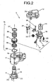
- the electric retracting unit 3 includes a shaft holder 9, a shaft 10, a gear case 11, a cover 12, a motor 13, a deceleration mechanism 14, a clutch mechanism 15, a plate 16, and a fixing plate 17.
- the gear case 11 and the cover 12 serve as a casing, and the deceleration mechanism 14 and the clutch mechanism 15 serve as a rotational force transmitting mechanism.
- the shaft holder 9 is fixed to the base 4, and the shaft 10 is integrally provided to the shaft holder 9.
- the shaft 10 is formed in a hollow, and a harness (not shown) is inserted through the hollow.
- the gear case 11 and the cover 12 are rotatably attached to the shaft 10.
- the attachment bracket 6 is attached to the gear case 11.
- the motor 13, the deceleration mechanism 14, the clutch mechanism 15, the plate 16, and the fixing plate 17 are housed in a housing 18 formed by the gear case 11 and the cover 12.
- the gear case 11 is closed on the lower side (the side of the shaft holder 9) and is open on the upper side (the side of the cover 12) to form a concave shape in section.
- An insertion hole 19 is formed in the closed portion of the gear case 11, into which the shaft 10 is inserted. With this configuration, the gear case 11 is rotatably attached to the shaft 10.
- a circular guide projection 20 and an arc-shaped stopper projection 21 are integrally provided on the upper surface of the shaft holder 9.
- the arc-shaped stopper projection 21 is positioned outside the guide projection 20.
- the stopper projection 21 has stopper surfaces 22 on both ends. In Fig. 2 , only one stopper surface 22 is shown.
- a circular guide groove 23 and an arc-shaped guide groove 24 are provided on the lower surface of the gear case 11.
- the guide groove 24 is positioned outside the guide groove 23 and has a width wider than that of the guide groove 23. Stopper surfaces 25 are provided at step portions formed between the guide grooves 23 and 24.
- the guide projection 20, the stopper projection 21, the guide groove 23, and the guide groove 24 are arranged around the shaft 10 in a concentric pattern.
- the guide projection 20 and the stopper projection 21 on the shaft holder 9 are engaged with the guide groove 23 and the guide groove 24 of the gear case 11, respectively.
- the guide grooves 23 and 24, the guide projection 20, and the stopper projection 21 function as a guide for the rotation of the gear case 11.
- Fig. 1 when the mirror assembly 2 rotates forward (counterclockwise) or backward (clockwise) from a normal position C for use in driving a vehicle to get to a mirror position A in which the mirror assembly 2 is inclined forward or a mirror position B in which the mirror assembly 2 is retracted, the stopper surface 25 comes into contact with the stopper surface 22 of the stopper projection 21. Thus, the rotation of the mirror assembly 2 is restricted, so that the mirror assembly 2 does not hit the vehicle body.
- the cover 12 is closed on the upper side and is open on the lower side (the side of the gear case 11) to form an inverted concave shape in section.
- a harness-through cylindrical portion 26 that communicates with the shaft 10 is integrally provided to the cover 12.
- the cover 12 is fitted and fixed to the outside edge of the opening of the gear case 11.
- the motor 13, the deceleration mechanism 14, the clutch mechanism 15, the plate 16, the fixing plate 17, and a substrate 27 are housed in the housing 18.
- the substrate 27 is attached to the plate 16, and a switch circuit (not shown), which controls the motor 13, is mounted on the substrate 27.
- An insertion hole 39 is formed in the cover 12 so that the shaft 10 is inserted through the insertion hole 39 to reach the harness-through cylindrical portion 26.
- the cover 12 is rotatably attached to the shaft 10 together with the gear case 11.
- the deceleration mechanism 14 and the clutch mechanism 15 that function as the rotational force transmitting mechanism are housed in the housing 18 so that they are arranged between a gear shaft 28 of the motor 13 and the shaft 10.
- the deceleration mechanism 14 and the clutch mechanism 15 transmit a rotation force of the motor 13 to the shaft 10.
- the motor 13, the deceleration mechanism 14, and the clutch mechanism 15 rotate the mirror assembly 2 with respect to the shaft 10.
- the deceleration mechanism 14 includes a first worm gear 29 as a first stage gear, a helical gear 30 as a second stage gear meshing with the first worm gear 29, a second worm gear 31 as a third stage gear, and a clutch gear 32 as a final stage gear meshing with the second worm gear 31.
- the first worm gear 29 is rotatably supported by the plate 16 through a pin 33.
- the first worm gear 29 is coupled to the gear shaft 28.
- the helical gear 30 is rotatably supported by the plate 16.
- the second worm gear 31 is rotatably supported by the gear case 11 and the fixing plate 17.
- the fixing plate 17 is fixed to the gear case 11 with a screw 34.
- the helical gear 30 and the second worm gear 31 are coupled to be integrally rotatable.
- the clutch mechanism 15 includes the clutch gear 32, a clutch holder 35, a spring 36, a push nut 37, and a washer 38.
- the clutch mechanism 15 is formed by sequentially fitting the washer 38, the clutch holder 35, the clutch gear 32, and the spring 36 over the shaft 10, and fixing the push nut 37 to the shaft 10.
- the spring 36 is in a compressed state.
- the clutch gear 32 and the clutch holder 35 are intermittently coupled to each other.
- the second worm gear 31 meshes with the clutch gear 32, so that a rotational force of the motor 13 is transmitted to the shaft 10.
- the first worm gear 29 includes the pin 33 serving as a shaft, a gear portion 63, and a shaft portion 42 that is integrally provided to one end of the gear portion 63.
- a coupling hole 43 is formed in the shaft portion 42 to extend from one end surface of the gear portion 63 in an axis direction.
- the coupling hole 43 has a butterfly-like shape in cross section in a direction perpendicular to the axis direction of the gear portion 63.
- the gear shaft 28 has a flat plate shape. As shown in Fig. 8 , the gear shaft 28 is inserted into the coupling hole 43 in the shaft portion 42, so that the gear shaft 28 is coupled to the gear portion 63.
- a circular fitting hole 44 is formed in the other end of the gear portion 63 to extend in the axis direction. Because the pin 33 has a simple shape, i.e., the pin 33 is a round bar with both ends hemispherically shaped, the pin 33 is manufactured at low cost. The pin 33 is fitted into the fitting hole 44 to the degree that the pin 33 does not come off easily from the fitting hole 44 in view of a sub-assembly structure. The pin 33 can be fitted into the fitting hole 44 more loosely or more tightly.
- the helical gear 30 includes a gear portion 64 and shaft portions 45.
- the shaft portions 45 are formed integrally with both ends of the gear portion 64 via step portions 46.
- a circular coupling hole 47 is formed in the helical gear 30 to penetrate therethrough in an axis direction.
- the inner surface in the middle of the coupling hole 47 forms two non-curved surfaces 65.
- the surfaces 65 are, for example, flat surfaces substantially parallel to each other.
- the second worm gear 31 includes a shaft portion 48 and a gear portion 66 that is provided at one end of the shaft portion 48.
- the shaft portion 48 and the gear portion 66 are integrated.
- a spherical projection 67 is integrally provided on each end of the second worm gear 31.
- the outer surface at the other end of the shaft portion 48 includes two non-curved surfaces 68.
- the surfaces 68 are, for example, flat surfaces substantially parallel to each other.
- the shaft portion 48 is inserted into the coupling hole 47, so that the shaft portion 48 and the coupling hole 47 are coupled to each other such that the shaft portion 48 can move in the axis direction and cannot rotate freely due to the fitting of the surfaces 65 and 68.
- the plate 16 has a substantially flat plate-like shape and closes the opening of the gear case 11.
- the plate 16 integrally includes a motor housing portion 49, a partition plate 69, a first worm gear housing portion 50, a substrate attaching portion 55, and elastic holding portions 56.
- the motor housing portion 49 is provided on one side (upper side) of the partition plate 69, and the first worm gear housing portion 50 is provided on the other side (lower side) of the partition plate 69.
- the substrate 27 is attached to the substrate attaching portion 55.
- a bearing hole 52 is formed in the partition plate 69, which is provided between the motor housing portion 49 and the first worm gear housing portion 50, for rotatably supporting the shaft portion 42.
- the first worm gear housing portion 50 integrally includes elastic plates 51 and a lower wall (bottom wall) 70.
- a bearing hole 53 for rotatably supporting the pin 33 is formed in the lower wall 70.
- Bearing holes 54 for supporting the shaft portions 45 are formed in the elastic plates 51, respectively.
- the fixing plate 17 is a member different from the plate 16.
- the fixing plate 17 includes radial bearing portions 57 on the side opposing the gear case 11.
- the fixing plate 17 is fixed to the gear case 11 with the screw 34, so that the radial bearing portions 57 support both ends of the second worm gear 31 together with the gear case 11.
- the radial bearing portions 57 and the gear case 11 suppress the radial force (the force in a radial direction) on both ends of the shaft portion 48 to stabilize the second worm gear 31.
- the gear case 11 is provided with a concave portion 40 in which the first worm gear housing portion 50 is housed.
- a pin retaining portion 58 is provided at the bottom of the concave portion 40. Furthermore, a hole 41 is formed in the gear case 11. Upon fixing the fixing plate 17 to the gear case 11 with the screw 34, the screw 34 is screwed into the hole 41.
- the gear case 11 includes thrust bearing portions 60.
- the thrust bearing portions 60 receive the thrust force (the force in a thrust direction) acting on the spherical projections 67.
- the gear case 11 includes radial bearing portions 61.
- the radial bearing portions 61 receive the radial force acting on the second worm gear 31.
- the cover 12 includes holding portions 62 that hold the elastic holding portions 56.
- the motor 13 is housed in the motor housing portion 49.
- the gear portion 63 is housed in the first worm gear housing portion 50, and the shaft portion 42 is rotatably supported by the bearing hole 52 in the plate 16.
- the gear shaft 28 is inserted into the coupling hole 43, so that the gear shaft 28 is coupled to the gear portion 63.
- the order of the above operations is not limited.
- the pin 33 is rotatably supported by the bearing hole 53 in the plate 16, and is inserted into the fitting hole 44 in the gear portion 63. Consequently, the gear portion 63 is rotatably supported by the plate 16 via the pin 33.
- the shaft portions 45 are rotatably supported by the bearing holes 54 in the elastic plates 51, respectively.
- the edges of the bearing holes 54 in the elastic plates 51 come into elastically close contact with the step portions 46 of the shaft portions 45 in such a manner to sandwich the step portions from outside.
- the first worm gear 29 and the helical gear 30 are meshed with each other.
- the motor 13, the first worm gear 29, the helical gear 30, and the plate 16 are sub-assembled.
- the shaft portion 48 is inserted into the coupling hole 47 in the helical gear 30 so that the shaft portion 48 is coupled to the helical gear 30 to be movable in the axis direction and not to be freely rotatable.
- the first worm gear housing portion 50 is housed in the concave portion 40 so that, as shown in Fig. 13 , the elastic plates 51 are inserted into the grooves 59.
- the spherical projections 67 are thrust-supported by the thrust bearing portions 60, and both ends and the middle portion of the second worm gear 31 are radially supported by the radial bearing portions 61.
- the fixing plate 17 is fixed to the gear case 11 with the screw 34.
- one end and the middle portion of the second worm gear 31 are radially supported by the radial bearing portions 57 and two of the three radial bearing portions 61.
- the radial force acting on the shaft portion 48 is suppressed by the radial bearing portions 57 and the radial bearing portions 61.
- the pin 33 comes into close contact with the pin retaining portion 58.
- the pin 33 is prevented from coming off from the plate 16, and the shaft portion 42 is prevented from coming off from the bearing hole 52.
- the shaft 10 is inserted into the insertion hole 19 in the gear case 11 to be rotatable.
- the washer 38, the clutch holder 35, the clutch gear 32, the spring 36, and the push nut 37 of the clutch mechanism 15 are assembled to the shaft 10.
- the cover 12 is fitted and fixed to the outside edge of the opening of the gear case 11, and the holding portions 62 are made in close contact with the elastic holding portions 56.
- the plate 16 to which the first worm gear 29 and the helical gear 30 are sub-assembled is elastically held by the gear case 11 and the cover 12.
- the gear case 11 of the electric retracting unit 3 is attached to the attachment bracket 6.
- the shaft holder 9 is fixed to the base 4.
- the door mirror devices 1 are mounted on the vehicle door by fixing the bases 4 to the right and left sides of the vehicle door.
- the motor 13 is driven by operating a switch (not shown) in the vehicle.
- the rotational force of the motor 13 is transmitted to the clutch gear 32 fixed to the shaft 10 via the gear shaft 28 and the deceleration mechanism 14.
- the second worm gear 31 rotates around the clutch gear 32 centering on the shaft 10.
- the mirror assembly 2 with the electric retracting unit 3 built in rotates between the normal position C and the mirror position B centering around the shaft 10 as shown in Fig. 1 .
- the switch circuit not shown
- the clutch gear 32 rotates against the pressing force of the spring 36, and the mesh engagement between the clutch gear 32 and the clutch holder 35 is released.
- the clutch of the clutch mechanism 15 is released, and the mirror assembly 2 rotates between the normal position C and the mirror position B, or between the normal position C and the mirror position A, for absorbing a shock.
- the clutch by the clutch mechanism 15 is released and the mirror assembly 2 rotates between the normal position C and the mirror position B, or between the normal position C and the mirror position A, in the same manner as the above.
- the shaft portions at both ends of the first stage gear in the rotational force transmitting mechanism i.e., the shaft portion 42 and the pin 33 of the first worm gear 29, are supported by the bearing holes 52 and 53 in the plate 16 as a single bearing member, respectively.
- the rotational central axis of the first worm gear 29 can be properly positioned. Therefore, the axial runout and the inclination of the first worm gear 29 are reliably prevented. This reduces an operation noise, resulting in improving a commercial value of the door mirror device 1.
- the first stage gear (the first worm gear 29), which is coupled to the gear shaft 28 and rotates at high speed, can exhibit improved durability.
- the shaft portion 42 is inserted into the bearing hole 52 in the plate 16, and the pin 33 is inserted into the bearing hole 53 in the plate 16 and the fitting hole 44 in the first worm gear 29.
- the shaft portion 42 and the pin 33 can be supported by the bearing hole 52 and the bearing hole 53 in the plate 16 as a single bearing member, respectively. Therefore, efficiency of assembling the first worm gear 29 to the plate 16 is improved.
- the first worm gear 29 is directly coupled to the gear shaft 28.
- a joint for coupling the first worm gear 29 to the motor 13 is not required, which results in reducing the number of parts of the door mirror device 1, thereby lowering manufacturing cost of the door mirror device 1.
- the first worm gear 29 and the helical gear 30 that meshes with the first worm gear 29 are supported by the plate 16 as a single bearing member.
- the rotational central axes of the first worm gear 29 and the helical gear 30 can be properly positioned, so that the relative positional relationship between the rotational central axes of the first worm gear 29 and the helical gear 30 can be appropriate. Therefore, the axial runout and the inclination of the first worm gear 29 and the helical gear 30 are reliably prevented, and the pitch between axes of the first worm gear 29 and the helical gear 30 becomes stabilized. This reduces the operation noise, resulting in improving a commercial value of the door mirror device 1.
- the first stage gear (the first worm gear 29), which is coupled to the gear shaft 28 and rotates at high speed, can exhibit improved durability.
- the motor 13, the first worm gear 29, the helical gear 30, and the plate 16 are sub-assembled.
- efficiency of assembling the motor 13, the deceleration mechanism 14, and the plate 16 is improved.
- efficiency of assembling the sub-assembly in which the motor 13, the first worm gear 29, the helical gear 30, and the plate 16 are assembled, to other parts such as the gear case 11, the cover 12, the clutch gear 32, and the clutch mechanism 15, is improved.
- the plate 16, which rotatably supports the first worm gear 29 coupled to the gear shaft 28 and the helical gear 30, and the fixing plate 17, which suppresses the radial force acting on the second worm gear 31 that meshes with the clutch gear 32, are different members, the radial force acting on the second worm gear 31 does not affect the plate 16.
- the first worm gear 29 and the helical gear 30, which are supported by the plate 16 are not affected.
- the first worm gear 29, the helical gear 30, the second worm gear 31 can rotate smoothly and properly.
- the operation noise can be reduced, and the strength of the gears does not decline because the gears mesh with each other properly, thereby improving the quality and the commercial value of the door mirror device 1.
- the gears themselves do not need high strength, it is possible to lower manufacturing cost of the door mirror device, and durability of the gears is increased.
- the plate 16 does not need to be fixed to the gear case 11 with a screw or the like. This results in reducing the number of parts of the door mirror device 1, thereby lowering manufacturing cost of the door mirror device 1 and improving efficiency of assembling operation. Moreover, the plate 16 is elastically held by the gear case 11 and the cover 12. Thus, even though the plate 16 is not fixed to the gear case 11, the plate 16 does not rattle, and even if the movement of the second worm gear 31 due to eccentricity of the shaft is transmitted to the helical gear 30, the plate 16 follows the movement of the second worm gear 31. Therefore, the pitch and the mesh engagement between the first worm gear 29 and the helical gear 30 are not affected by the movement of the second worm gear 31.
- the fixing plate 17 and the plate 16 are formed with separate members, the fixing plate 17 can be a small fixing plate simply having a size sufficient for suppressing the radial force acting on the second worm gear 31. In this case, no particular problem is caused by providing the fixing plate 17 and the plate 16 as separate members.
- the present invention is applied to the electric retractable door mirror device.
- the present invention can be applied to other vehicle mirror devices including vehicle outside mirror devices such as a vehicle fender mirror.
Description
- The present invention relates to a vehicle outside mirror device.
-
European Patent Applications Laid-open Publication Number EP 1 634 772 A2 andEP 1 275 558 A2 disclose an outside mirror device for a vehicle according to the preamble of claim 1. - A further conventional vehicle outside mirror device, such as the one disclosed in
Japanese Patent Application Laid-open No. 2004-182117 - However, in the conventional vehicle outside mirror device, because the both ends of the worm gear are supported by the separate bearing members, respectively, an axial runout and an inclination of the worm gear may occur.
- It is an object of the present invention to at least partially solve the problems in the conventional technology.
- An outside mirror device for a vehicle, according to one aspect of the present invention, includes a mirror assembly that is rotatably attached to a body of the vehicle through an electric retracting unit and a base. The electric retracting unit includes a shaft holder that is fixed to the base, a shaft that is provided on the shaft holder, a casing to which the mirror assembly is attached, which is rotatably attached to the shaft, a motor that outputs a rotational force, a rotational force transmitting mechanism that transmits the rotational force to the mirror assembly, and a bearing member that rotatably supports a first stage gear of the rotational force transmitting mechanism coupled to a shaft of the motor. The first stage gear includes a gear portion having a fitting hole at a first end thereof, a pin that is fitted into the fitting hole, and a shaft portion provided at a second end of the gear portion. The bearing member includes bearing holes that support the shaft portion and the pin, respectively. The casing includes a pin retaining portion that prevents the pin from coming off.
- The above and other objects, features, advantages and technical and industrial significance of this invention will be better understood by reading the following detailed description of presently preferred embodiments of the invention which are subject to the dependent claims, when considered in connection with the accompanying drawings.
-
-
Fig. 1 is a schematic diagram of a vehicle outside mirror device according to an embodiment of the present invention; -
Fig. 2 is an exploded perspective view of an electric retracting unit shown inFig. 1 ; -
Fig. 3 is a vertical cross section of the electric retracting unit; -
Fig. 4 is a horizontal cross section of the electric retracting unit; -
Fig. 5 is a bottom view of a gear case of the electric retracting unit; -
Fig. 6 is a plan view of the electric retracting unit with a cover removed; -
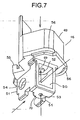
Fig. 7 is a perspective bottom view of a plate that functions as a bearing member shown inFig. 2 ; -
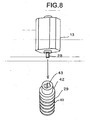
Fig. 8 is a schematic diagram for explaining a process of inserting a gear shaft of a motor into a coupling hole in a first worm gear; -
Fig. 9 is a schematic diagram for explaining a process of assembling the motor and the first worm gear to the plate; -
Fig. 10 is a schematic diagram for explaining a process of assembling a sub-assembly, in which the plate, the motor, and the first worm gear with the pin are assembled, to a gear case, and a process of fixing a fixing plate to the gear case; -
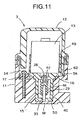
Fig. 11 is a schematic diagram for explaining a state where the sub-assembly shown inFig. 10 and the fixing plate are housed in a housing formed by the gear case and the cover; -
Fig. 12 is a schematic diagram for explaining a process of assembling the motor and a helical gear to the plate; -
Fig. 13 is a schematic diagram for explaining a process of assembling a sub-assembly, in which the plate, the motor, and the helical gear are assembled, to the gear case, a process of coupling a second worm gear to the helical gear, and a process of fixing the fixing plate to the gear case; and -
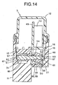
Fig. 14 is a schematic diagram for explaining a state where the sub-assembly shown inFig. 13 , the second worm gear, and the fixing plate are housed in the housing formed by the gear case and the cover. - Exemplary embodiments of the present invention are explained in detail below with reference to the accompanying drawings.
-
Fig. 1 is a schematic diagram of an electric retractable door mirror device (hereinafter, "a door mirror device") 1 that is a vehicle outside mirror device according to an embodiment of the present invention. The door mirror device 1 is mounted on each of a driver side (right side) door (not shown) and a passenger side (left side) door (not shown) of a vehicle. The door mirror device 1 shown inFig. 1 is mounted on the right door. A door mirror device mounted on the left side door has a configuration substantially symmetric to the door mirror device 1. - As shown in
Fig. 1 , the door mirror device 1 including amirror assembly 2 is rotatably attached to a vehicle body (e.g., a door) (not shown) via anelectric retracting unit 3 and a base 4 that is fixed to the door. - The
mirror assembly 2 includes amirror housing 5, anattachment bracket 6, adriving unit 7, and amirror unit 8. Theattachment bracket 6 is attached to the inside of themirror housing 5, and thedriving unit 7 is attached to theattachment bracket 6. Themirror unit 8 is attached to thedriving unit 7 so that themirror unit 8 inclined in the vertical and horizontal directions. - As shown in
Figs. 1 and2 , theelectric retracting unit 3 includes ashaft holder 9, ashaft 10, agear case 11, acover 12, amotor 13, adeceleration mechanism 14, aclutch mechanism 15, aplate 16, and afixing plate 17. - The
gear case 11 and thecover 12 serve as a casing, and thedeceleration mechanism 14 and theclutch mechanism 15 serve as a rotational force transmitting mechanism. - The
shaft holder 9 is fixed to the base 4, and theshaft 10 is integrally provided to theshaft holder 9. Theshaft 10 is formed in a hollow, and a harness (not shown) is inserted through the hollow. Thegear case 11 and thecover 12 are rotatably attached to theshaft 10. Theattachment bracket 6 is attached to thegear case 11. Themotor 13, thedeceleration mechanism 14, theclutch mechanism 15, theplate 16, and thefixing plate 17 are housed in ahousing 18 formed by thegear case 11 and thecover 12. - As shown in
Figs. 2 to 6 ,10 ,11 ,13 , and14 , thegear case 11 is closed on the lower side (the side of the shaft holder 9) and is open on the upper side (the side of the cover 12) to form a concave shape in section. Aninsertion hole 19 is formed in the closed portion of thegear case 11, into which theshaft 10 is inserted. With this configuration, thegear case 11 is rotatably attached to theshaft 10. - As shown in
Figs. 2 and3 , acircular guide projection 20 and an arc-shaped stopper projection 21 are integrally provided on the upper surface of theshaft holder 9. The arc-shaped stopper projection 21 is positioned outside theguide projection 20. Thestopper projection 21 has stoppersurfaces 22 on both ends. InFig. 2 , only onestopper surface 22 is shown. As shown inFigs. 3 and5 , acircular guide groove 23 and an arc-shaped guide groove 24 are provided on the lower surface of thegear case 11. Theguide groove 24 is positioned outside theguide groove 23 and has a width wider than that of theguide groove 23.Stopper surfaces 25 are provided at step portions formed between theguide grooves guide projection 20, thestopper projection 21, theguide groove 23, and theguide groove 24 are arranged around theshaft 10 in a concentric pattern. - The
guide projection 20 and thestopper projection 21 on theshaft holder 9 are engaged with theguide groove 23 and theguide groove 24 of thegear case 11, respectively. When themirror assembly 2 rotates with respect to the base 4, i.e., when thegear case 11 rotates with respect to theshaft holder 9, theguide grooves guide projection 20, and thestopper projection 21 function as a guide for the rotation of thegear case 11. - As shown in
Fig. 1 , when themirror assembly 2 rotates forward (counterclockwise) or backward (clockwise) from a normal position C for use in driving a vehicle to get to a mirror position A in which themirror assembly 2 is inclined forward or a mirror position B in which themirror assembly 2 is retracted, thestopper surface 25 comes into contact with thestopper surface 22 of thestopper projection 21. Thus, the rotation of themirror assembly 2 is restricted, so that themirror assembly 2 does not hit the vehicle body. - As shown in
Figs. 2 ,3 ,7 ,8 ,10 , and11 , thecover 12 is closed on the upper side and is open on the lower side (the side of the gear case 11) to form an inverted concave shape in section. A harness-throughcylindrical portion 26 that communicates with theshaft 10 is integrally provided to thecover 12. Thecover 12 is fitted and fixed to the outside edge of the opening of thegear case 11. - The
motor 13, thedeceleration mechanism 14, theclutch mechanism 15, theplate 16, the fixingplate 17, and asubstrate 27 are housed in thehousing 18. Thesubstrate 27 is attached to theplate 16, and a switch circuit (not shown), which controls themotor 13, is mounted on thesubstrate 27. - An
insertion hole 39 is formed in thecover 12 so that theshaft 10 is inserted through theinsertion hole 39 to reach the harness-throughcylindrical portion 26. With this configuration, thecover 12 is rotatably attached to theshaft 10 together with thegear case 11. - As shown in
Figs. 2 to 4 ,6 ,7 , and10 , thedeceleration mechanism 14 and theclutch mechanism 15 that function as the rotational force transmitting mechanism are housed in thehousing 18 so that they are arranged between agear shaft 28 of themotor 13 and theshaft 10. Thedeceleration mechanism 14 and theclutch mechanism 15 transmit a rotation force of themotor 13 to theshaft 10. In other words, themotor 13, thedeceleration mechanism 14, and theclutch mechanism 15 rotate themirror assembly 2 with respect to theshaft 10. - The
deceleration mechanism 14 includes afirst worm gear 29 as a first stage gear, ahelical gear 30 as a second stage gear meshing with thefirst worm gear 29, asecond worm gear 31 as a third stage gear, and aclutch gear 32 as a final stage gear meshing with thesecond worm gear 31. - The
first worm gear 29 is rotatably supported by theplate 16 through apin 33. Thefirst worm gear 29 is coupled to thegear shaft 28. Thehelical gear 30 is rotatably supported by theplate 16. Thesecond worm gear 31 is rotatably supported by thegear case 11 and the fixingplate 17. The fixingplate 17 is fixed to thegear case 11 with ascrew 34. Thehelical gear 30 and thesecond worm gear 31 are coupled to be integrally rotatable. - The
clutch mechanism 15 includes theclutch gear 32, aclutch holder 35, aspring 36, apush nut 37, and awasher 38. Theclutch mechanism 15 is formed by sequentially fitting thewasher 38, theclutch holder 35, theclutch gear 32, and thespring 36 over theshaft 10, and fixing thepush nut 37 to theshaft 10. Thespring 36 is in a compressed state. Theclutch gear 32 and theclutch holder 35 are intermittently coupled to each other. Thesecond worm gear 31 meshes with theclutch gear 32, so that a rotational force of themotor 13 is transmitted to theshaft 10. - As shown in
Figs. 2 to 4 , and8 to 11 , thefirst worm gear 29 includes thepin 33 serving as a shaft, agear portion 63, and ashaft portion 42 that is integrally provided to one end of thegear portion 63. Acoupling hole 43 is formed in theshaft portion 42 to extend from one end surface of thegear portion 63 in an axis direction. Thecoupling hole 43 has a butterfly-like shape in cross section in a direction perpendicular to the axis direction of thegear portion 63. Thegear shaft 28 has a flat plate shape. As shown inFig. 8 , thegear shaft 28 is inserted into thecoupling hole 43 in theshaft portion 42, so that thegear shaft 28 is coupled to thegear portion 63. - A circular
fitting hole 44 is formed in the other end of thegear portion 63 to extend in the axis direction. Because thepin 33 has a simple shape, i.e., thepin 33 is a round bar with both ends hemispherically shaped, thepin 33 is manufactured at low cost. Thepin 33 is fitted into thefitting hole 44 to the degree that thepin 33 does not come off easily from thefitting hole 44 in view of a sub-assembly structure. Thepin 33 can be fitted into thefitting hole 44 more loosely or more tightly. - As shown in
Figs. 2 to 4 , and12 to 14 , thehelical gear 30 includes agear portion 64 andshaft portions 45. Theshaft portions 45 are formed integrally with both ends of thegear portion 64 viastep portions 46. Acircular coupling hole 47 is formed in thehelical gear 30 to penetrate therethrough in an axis direction. The inner surface in the middle of thecoupling hole 47 forms twonon-curved surfaces 65. Thesurfaces 65 are, for example, flat surfaces substantially parallel to each other. - As shown in
Figs. 2 to 4 ,13 , and14 , thesecond worm gear 31 includes ashaft portion 48 and agear portion 66 that is provided at one end of theshaft portion 48. Theshaft portion 48 and thegear portion 66 are integrated. Aspherical projection 67 is integrally provided on each end of thesecond worm gear 31. The outer surface at the other end of theshaft portion 48 includes twonon-curved surfaces 68. Thesurfaces 68 are, for example, flat surfaces substantially parallel to each other. Theshaft portion 48 is inserted into thecoupling hole 47, so that theshaft portion 48 and thecoupling hole 47 are coupled to each other such that theshaft portion 48 can move in the axis direction and cannot rotate freely due to the fitting of thesurfaces - As shown in
Figs. 2 ,3 ,6 ,7 ,9 to 14 , theplate 16 has a substantially flat plate-like shape and closes the opening of thegear case 11. Theplate 16 integrally includes amotor housing portion 49, apartition plate 69, a first wormgear housing portion 50, asubstrate attaching portion 55, andelastic holding portions 56. Themotor housing portion 49 is provided on one side (upper side) of thepartition plate 69, and the first wormgear housing portion 50 is provided on the other side (lower side) of thepartition plate 69. Thesubstrate 27 is attached to thesubstrate attaching portion 55. A bearinghole 52 is formed in thepartition plate 69, which is provided between themotor housing portion 49 and the first wormgear housing portion 50, for rotatably supporting theshaft portion 42. The first wormgear housing portion 50 integrally includeselastic plates 51 and a lower wall (bottom wall) 70. A bearinghole 53 for rotatably supporting thepin 33 is formed in thelower wall 70. Bearing holes 54 for supporting theshaft portions 45 are formed in theelastic plates 51, respectively. Themotor 13, thefirst worm gear 29, thehelical gear 30, and theplate 16 are sub-assembled. - As shown in
Figs. 2 ,6 ,10 ,11 ,13 , and14 , the fixingplate 17 is a member different from theplate 16. The fixingplate 17 includesradial bearing portions 57 on the side opposing thegear case 11. The fixingplate 17 is fixed to thegear case 11 with thescrew 34, so that theradial bearing portions 57 support both ends of thesecond worm gear 31 together with thegear case 11. In other words, theradial bearing portions 57 and thegear case 11 suppress the radial force (the force in a radial direction) on both ends of theshaft portion 48 to stabilize thesecond worm gear 31. - As shown in
Figs. 10 ,11 ,13 , and14 , thegear case 11 is provided with aconcave portion 40 in which the first wormgear housing portion 50 is housed. - As shown in
Figs. 10 and11 , apin retaining portion 58 is provided at the bottom of theconcave portion 40. Furthermore, ahole 41 is formed in thegear case 11. Upon fixing the fixingplate 17 to thegear case 11 with thescrew 34, thescrew 34 is screwed into thehole 41. - As shown in
Figs. 13 and14 ,grooves 59 are formed on the bottom of theconcave portion 40. Theelastic plates 51 of theplate 16 are inserted into thegrooves 59. Thegear case 11 includes thrustbearing portions 60. Thethrust bearing portions 60 receive the thrust force (the force in a thrust direction) acting on thespherical projections 67. Furthermore, thegear case 11 includesradial bearing portions 61. Theradial bearing portions 61 receive the radial force acting on thesecond worm gear 31. - As shown in
Figs. 10 and11 , thecover 12 includes holdingportions 62 that hold theelastic holding portions 56. - A process of assembling the
gear case 11, thecover 12, themotor 13, thedeceleration mechanism 14, theplate 16, and the fixingplate 17 in theelectric retracting unit 3 is explained below. - First, as shown in
Figs. 9 and12 , themotor 13 is housed in themotor housing portion 49. Then, as shown inFig. 9 , thegear portion 63 is housed in the first wormgear housing portion 50, and theshaft portion 42 is rotatably supported by the bearinghole 52 in theplate 16. Thegear shaft 28 is inserted into thecoupling hole 43, so that thegear shaft 28 is coupled to thegear portion 63. The order of the above operations is not limited. As shown inFig. 9 , thepin 33 is rotatably supported by the bearinghole 53 in theplate 16, and is inserted into thefitting hole 44 in thegear portion 63. Consequently, thegear portion 63 is rotatably supported by theplate 16 via thepin 33. - Subsequently, as shown in
Fig. 12 , theshaft portions 45 are rotatably supported by the bearing holes 54 in theelastic plates 51, respectively. At this time, the edges of the bearing holes 54 in theelastic plates 51 come into elastically close contact with thestep portions 46 of theshaft portions 45 in such a manner to sandwich the step portions from outside. Thefirst worm gear 29 and thehelical gear 30 are meshed with each other. Thus, as shown inFigs. 10 and13 , themotor 13, thefirst worm gear 29, thehelical gear 30, and theplate 16 are sub-assembled. - Subsequently, as shown in
Fig. 13 , theshaft portion 48 is inserted into thecoupling hole 47 in thehelical gear 30 so that theshaft portion 48 is coupled to thehelical gear 30 to be movable in the axis direction and not to be freely rotatable. As shown inFig. 10 , the first wormgear housing portion 50 is housed in theconcave portion 40 so that, as shown inFig. 13 , theelastic plates 51 are inserted into thegrooves 59. Simultaneously, thespherical projections 67 are thrust-supported by thethrust bearing portions 60, and both ends and the middle portion of thesecond worm gear 31 are radially supported by theradial bearing portions 61. - Subsequently, as shown in
Figs. 10 and11 , the fixingplate 17 is fixed to thegear case 11 with thescrew 34. Whereby, one end and the middle portion of thesecond worm gear 31 are radially supported by theradial bearing portions 57 and two of the threeradial bearing portions 61. The radial force acting on theshaft portion 48 is suppressed by theradial bearing portions 57 and theradial bearing portions 61. Thepin 33 comes into close contact with thepin retaining portion 58. Thus, thepin 33 is prevented from coming off from theplate 16, and theshaft portion 42 is prevented from coming off from the bearinghole 52. - Subsequently, the
shaft 10 is inserted into theinsertion hole 19 in thegear case 11 to be rotatable. Thewasher 38, theclutch holder 35, theclutch gear 32, thespring 36, and thepush nut 37 of theclutch mechanism 15 are assembled to theshaft 10. - Finally, as shown in
Figs. 10 and13 , thecover 12 is fitted and fixed to the outside edge of the opening of thegear case 11, and the holdingportions 62 are made in close contact with theelastic holding portions 56. Whereby, theplate 16, to which thefirst worm gear 29 and thehelical gear 30 are sub-assembled, is elastically held by thegear case 11 and thecover 12. - The
gear case 11, thecover 12, themotor 13, thedeceleration mechanism 14, theplate 16, and the fixingplate 17 are assembled as shown inFigs. 11 and14 , and theshaft holder 9, theshaft 10, and theclutch mechanism 15 are assembled as shown inFig. 3 . Thus, the assembling of theelectric retracting unit 3 is completed. - The
gear case 11 of theelectric retracting unit 3 is attached to theattachment bracket 6. Theshaft holder 9 is fixed to the base 4. Thus, the assembling of the door mirror device 1 is completed. The door mirror devices 1 are mounted on the vehicle door by fixing the bases 4 to the right and left sides of the vehicle door. - For actuating the door mirror device 1, first, the
motor 13 is driven by operating a switch (not shown) in the vehicle. The rotational force of themotor 13 is transmitted to theclutch gear 32 fixed to theshaft 10 via thegear shaft 28 and thedeceleration mechanism 14. At this time, because theclutch gear 32 is nonrotatable with respect to theshaft 10, thesecond worm gear 31 rotates around theclutch gear 32 centering on theshaft 10. With the rotation of thesecond worm gear 31, themirror assembly 2 with theelectric retracting unit 3 built in rotates between the normal position C and the mirror position B centering around theshaft 10 as shown inFig. 1 . When themirror assembly 2 reaches the normal position C or the mirror position B, the current flowing into themotor 13 is cut off by a switching operation by the switch circuit (not shown), and themirror assembly 2 stops at the normal position C or the mirror position B. - When a load is applied to the
mirror assembly 2 from the front side or the rear side, theclutch gear 32 rotates against the pressing force of thespring 36, and the mesh engagement between theclutch gear 32 and theclutch holder 35 is released. Whereby, the clutch of theclutch mechanism 15 is released, and themirror assembly 2 rotates between the normal position C and the mirror position B, or between the normal position C and the mirror position A, for absorbing a shock. When themirror assembly 2 is manually rotated from forward or backward, the clutch by theclutch mechanism 15 is released and themirror assembly 2 rotates between the normal position C and the mirror position B, or between the normal position C and the mirror position A, in the same manner as the above. - According to the embodiment, the shaft portions at both ends of the first stage gear in the rotational force transmitting mechanism, i.e., the
shaft portion 42 and thepin 33 of thefirst worm gear 29, are supported by the bearing holes 52 and 53 in theplate 16 as a single bearing member, respectively. Thus, the rotational central axis of thefirst worm gear 29 can be properly positioned. Therefore, the axial runout and the inclination of thefirst worm gear 29 are reliably prevented. This reduces an operation noise, resulting in improving a commercial value of the door mirror device 1. In addition, the first stage gear (the first worm gear 29), which is coupled to thegear shaft 28 and rotates at high speed, can exhibit improved durability. - Furthermore, according to the embodiment, the
shaft portion 42 is inserted into the bearinghole 52 in theplate 16, and thepin 33 is inserted into the bearinghole 53 in theplate 16 and thefitting hole 44 in thefirst worm gear 29. Thus, theshaft portion 42 and thepin 33 can be supported by the bearinghole 52 and thebearing hole 53 in theplate 16 as a single bearing member, respectively. Therefore, efficiency of assembling thefirst worm gear 29 to theplate 16 is improved. - Moreover, according to the embodiment, the
first worm gear 29 is directly coupled to thegear shaft 28. Thus, a joint for coupling thefirst worm gear 29 to themotor 13 is not required, which results in reducing the number of parts of the door mirror device 1, thereby lowering manufacturing cost of the door mirror device 1. - Furthermore, according to the embodiment, the
first worm gear 29 and thehelical gear 30 that meshes with thefirst worm gear 29 are supported by theplate 16 as a single bearing member. Thus, the rotational central axes of thefirst worm gear 29 and thehelical gear 30 can be properly positioned, so that the relative positional relationship between the rotational central axes of thefirst worm gear 29 and thehelical gear 30 can be appropriate. Therefore, the axial runout and the inclination of thefirst worm gear 29 and thehelical gear 30 are reliably prevented, and the pitch between axes of thefirst worm gear 29 and thehelical gear 30 becomes stabilized. This reduces the operation noise, resulting in improving a commercial value of the door mirror device 1. In addition, the first stage gear (the first worm gear 29), which is coupled to thegear shaft 28 and rotates at high speed, can exhibit improved durability. - Moreover, according to the embodiment, the
motor 13, thefirst worm gear 29, thehelical gear 30, and theplate 16 are sub-assembled. Thus, efficiency of assembling themotor 13, thedeceleration mechanism 14, and theplate 16 is improved. In addition, efficiency of assembling the sub-assembly in which themotor 13, thefirst worm gear 29, thehelical gear 30, and theplate 16 are assembled, to other parts such as thegear case 11, thecover 12, theclutch gear 32, and theclutch mechanism 15, is improved. - Particularly, because the
plate 16, which rotatably supports thefirst worm gear 29 coupled to thegear shaft 28 and thehelical gear 30, and the fixingplate 17, which suppresses the radial force acting on thesecond worm gear 31 that meshes with theclutch gear 32, are different members, the radial force acting on thesecond worm gear 31 does not affect theplate 16. For example, because displacement or deformation of the fixingplate 17 due to the radial force acting on thesecond worm gear 31 is not transmitted to theplate 16, thefirst worm gear 29 and thehelical gear 30, which are supported by theplate 16, are not affected. Thus, thefirst worm gear 29, thehelical gear 30, thesecond worm gear 31 can rotate smoothly and properly. Consequently, the operation noise can be reduced, and the strength of the gears does not decline because the gears mesh with each other properly, thereby improving the quality and the commercial value of the door mirror device 1. In other words, because the gears themselves do not need high strength, it is possible to lower manufacturing cost of the door mirror device, and durability of the gears is increased. - Furthermore, according to the embodiment, because the radial force acting on the
second worm gear 31 does not affect theplate 16, theplate 16 does not need to be fixed to thegear case 11 with a screw or the like. This results in reducing the number of parts of the door mirror device 1, thereby lowering manufacturing cost of the door mirror device 1 and improving efficiency of assembling operation. Moreover, theplate 16 is elastically held by thegear case 11 and thecover 12. Thus, even though theplate 16 is not fixed to thegear case 11, theplate 16 does not rattle, and even if the movement of thesecond worm gear 31 due to eccentricity of the shaft is transmitted to thehelical gear 30, theplate 16 follows the movement of thesecond worm gear 31. Therefore, the pitch and the mesh engagement between thefirst worm gear 29 and thehelical gear 30 are not affected by the movement of thesecond worm gear 31. - Moreover, according to the embodiment, because the fixing
plate 17 and theplate 16 are formed with separate members, the fixingplate 17 can be a small fixing plate simply having a size sufficient for suppressing the radial force acting on thesecond worm gear 31. In this case, no particular problem is caused by providing the fixingplate 17 and theplate 16 as separate members. - In the embodiment described above, the present invention is applied to the electric retractable door mirror device. However, the present invention can be applied to other vehicle mirror devices including vehicle outside mirror devices such as a vehicle fender mirror.
Claims (4)
- An outside mirror device for a vehicle, the outside mirror device including a mirror assembly (2) that is rotatably attached to a body of the vehicle through an electric retracting unit (3) and a base (4), wherein
the electric retracting unit (3) includes
a shaft holder (9) that is fixed to the base (4),
a shaft (10) that is provided on the shaft holder (9),
a casing (11, 12) to which the mirror assembly (2) is attached, the casing (11,12) rotatably attached to the shaft (10),
a motor (13) that outputs a rotational force,
a rotational force transmitting mechanism (14, 15) that transmits the rotational force to the mirror assembly (2), and
a bearing member (16) that rotatably supports a first stage gear (29) of the rotational force transmitting mechanism (14, 15) coupled to a shaft (28) of the motor (13),
the first stage gear (29) includes
a gear portion (63) having a fitting hole (44) at a first end thereof,
a pin (33) that is fitted into the fitting hole (44), and
a shaft portion (42) provided at a second end of the gear portion (63);,
and
the casing (11, 12) includes a pin retaining portion (58) that prevents the pin (33) from coming off,
characterized in
that the bearing member (16) includes bearing holes (52, 53) that support the shaft portion (42) and the pin (33), respectively. - The outside mirror device according to claim 1, characterized in that the first stage gear (29) is directly coupled to the shaft (28) of the motor (13).
- The outside mirror device according to claim 1 or 2, characterized in that
the rotational force transmitting mechanism (14, 15) includes the first stage gear (29) and a second stage gear (30) that meshes with the first stage gear (29),
the second stage gear (30) includes shaft portions (45, 45) at both ends,
the bearing member (16) includes elastic plates (51, 51) having bearing holes (54, 54), respectively, and
the shaft portions (45, 45) of the second stage gear (30) are rotatably supported by the bearing holes (54, 54) of the elastic plates (51, 51), respectively. - The outside mirror device according to claim 3, characterized in that the motor (13), the gear portion (63) and the pin (33) of the first stage gear (29), the second stage gear (30) and the bearing member (16) are sub-assembled.
Applications Claiming Priority (1)
| Application Number | Priority Date | Filing Date | Title |
|---|---|---|---|
| JP2006273094A JP2008087707A (en) | 2006-10-04 | 2006-10-04 | Outside mirror device for vehicle |
Publications (2)
| Publication Number | Publication Date |
|---|---|
| EP1908633A1 EP1908633A1 (en) | 2008-04-09 |
| EP1908633B1 true EP1908633B1 (en) | 2009-04-08 |
Family
ID=38895703
Family Applications (1)
| Application Number | Title | Priority Date | Filing Date |
|---|---|---|---|
| EP07019485A Expired - Fee Related EP1908633B1 (en) | 2006-10-04 | 2007-10-04 | Vehicle outside mirror device |
Country Status (6)
| Country | Link |
|---|---|
| US (1) | US7441912B2 (en) |
| EP (1) | EP1908633B1 (en) |
| JP (1) | JP2008087707A (en) |
| KR (1) | KR100898024B1 (en) |
| CN (1) | CN100538121C (en) |
| DE (1) | DE602007000852D1 (en) |
Families Citing this family (19)
| Publication number | Priority date | Publication date | Assignee | Title |
|---|---|---|---|---|
| JP4676301B2 (en) * | 2005-10-14 | 2011-04-27 | 株式会社東海理化電機製作所 | Mirror device for vehicle |
| JP2008087706A (en) * | 2006-10-04 | 2008-04-17 | Ichikoh Ind Ltd | Outside mirror device for vehicle |
| JP4807213B2 (en) | 2006-10-04 | 2011-11-02 | 市光工業株式会社 | Outside mirror device for vehicle |
| JP2008296719A (en) * | 2007-05-31 | 2008-12-11 | Ichikoh Ind Ltd | Vehicular outside mirror device |
| EP2301804B1 (en) | 2009-09-23 | 2011-12-28 | SMR Patents S.à.r.l. | Hinge construction |
| JP5324410B2 (en) * | 2009-12-11 | 2013-10-23 | 株式会社村上開明堂 | Manual storage / electrically retractable shared base for vehicle door mirrors, manually retractable vehicle door mirrors, electric retractable vehicle door mirrors, and selective manufacturing methods for manually retractable or electrically retractable door mirrors |
| JP5552854B2 (en) * | 2010-03-17 | 2014-07-16 | 市光工業株式会社 | Outside mirror device for vehicle |
| JP2011194925A (en) * | 2010-03-17 | 2011-10-06 | Ichikoh Ind Ltd | Vehicle outside mirror device |
| JP5418356B2 (en) * | 2010-03-26 | 2014-02-19 | 市光工業株式会社 | Outside mirror device for vehicle |
| JP5556621B2 (en) * | 2010-11-26 | 2014-07-23 | 市光工業株式会社 | Outside mirror device for vehicle |
| JP2012116322A (en) * | 2010-11-30 | 2012-06-21 | Tokai Rika Co Ltd | Mirror device for vehicle |
| JP2013005017A (en) * | 2011-06-13 | 2013-01-07 | Sony Corp | Image pickup apparatus, image pickup apparatus control method, and program |
| US9067541B2 (en) * | 2011-10-31 | 2015-06-30 | Magna Mirrors Of America, Inc. | Exterior mirror assembly with actuator |
| JP6035944B2 (en) * | 2012-07-25 | 2016-11-30 | 市光工業株式会社 | Electric storage unit for vehicle outside mirror device, vehicle outside mirror device, and method for manufacturing electric storage unit for vehicle outside mirror device |
| NL2011552C2 (en) * | 2013-10-03 | 2015-04-07 | Mci Mirror Controls Int Nl Bv | MIRROR ADJUSTMENT DEVICE WITH GAME REPRESSION. |
| JP6604733B2 (en) | 2015-03-31 | 2019-11-13 | 株式会社村上開明堂 | Electric retractable visual recognition device for vehicles |
| EP3208152B1 (en) * | 2016-02-16 | 2019-04-10 | Magna Auteca GmbH | Folding device for an external mirror |
| JP7172162B2 (en) * | 2018-06-20 | 2022-11-16 | 市光工業株式会社 | Electric storage unit for vehicle outside mirror device, vehicle outside mirror device |
| CN109733286B (en) * | 2019-01-10 | 2021-06-29 | 湄洲湾职业技术学院 | Control circuit for driving automobile rearview mirror base to be folded |
Family Cites Families (21)
| Publication number | Priority date | Publication date | Assignee | Title |
|---|---|---|---|---|
| EP0146888B1 (en) | 1983-12-17 | 1989-03-22 | Ichikoh Industries Limited | Outside rear view mirror |
| JPS60148738A (en) * | 1984-01-12 | 1985-08-06 | Ichikoh Ind Ltd | Door mirror structure |
| DE3882896T2 (en) * | 1987-10-27 | 1993-11-18 | Ichikoh Industries Ltd | Electrically swiveling door mirror. |
| US5172884A (en) | 1989-08-31 | 1992-12-22 | Ichikoh Industries, Ltd. | Motor-driven foldable type door mirror |
| US4981349A (en) | 1989-09-01 | 1991-01-01 | Kabushiki Kaisha Matsuyama Seisakusho | Rearview mirror assembly for automobiles including positioning means with a recess surface extending uniformly horizontally |
| US5369530A (en) | 1990-10-24 | 1994-11-29 | Ichikoh Industries Ltd. | Stay housable type motor driven mirror |
| JP3208994B2 (en) * | 1994-06-09 | 2001-09-17 | 市光工業株式会社 | Drive device for rearview mirror device for vehicles |
| JP3008334U (en) * | 1994-08-25 | 1995-03-14 | 株式会社村上開明堂 | Electric retractable door mirror deceleration mechanism |
| KR100198321B1 (en) * | 1995-09-22 | 1999-06-15 | 모치마루 마모루 | Positioning device for an automobile's rear mirror |
| DE19833514B4 (en) | 1997-07-30 | 2005-04-28 | Buhler Motor Gmbh | Drive for folding down a motor vehicle rearview mirror |
| JP3872639B2 (en) | 2000-08-31 | 2007-01-24 | 株式会社村上開明堂 | Electric retractable door mirror |
| JP3887543B2 (en) * | 2001-03-19 | 2007-02-28 | 株式会社東海理化電機製作所 | Mirror device for vehicle |
| DE60216337T2 (en) * | 2001-03-19 | 2007-03-15 | Kabushiki Kaisha Tokai-Rika-Denki-Seisakusho | Automotive mirror assembly |
| JP4633299B2 (en) | 2001-07-12 | 2011-02-16 | 株式会社村上開明堂 | Reducer and electric retractable door mirror provided with the reducer |
| JP2003127775A (en) | 2001-10-29 | 2003-05-08 | Tokai Rika Co Ltd | Vehicular mirror |
| JP2004009806A (en) * | 2002-06-04 | 2004-01-15 | Ichikoh Ind Ltd | Outer mirror for vehicle |
| JP4054252B2 (en) | 2002-12-04 | 2008-02-27 | 株式会社東海理化電機製作所 | Mirror device for vehicle and storage mechanism for vehicle outer mirror device |
| JP4122993B2 (en) | 2003-02-04 | 2008-07-23 | 市光工業株式会社 | Electric retractable door mirror |
| JP2005008141A (en) * | 2003-05-27 | 2005-01-13 | Ichikoh Ind Ltd | Mirror device for vehicle |
| JP2006076408A (en) * | 2004-09-08 | 2006-03-23 | Tokai Rika Co Ltd | Accommodating mechanism of outer mirror device for vehicle |
| JP2006321467A (en) * | 2005-04-19 | 2006-11-30 | Ichikoh Ind Ltd | Door mirror device for vehicle |
-
2006
- 2006-10-04 JP JP2006273094A patent/JP2008087707A/en active Pending
-
2007
- 2007-08-31 KR KR1020070088231A patent/KR100898024B1/en not_active IP Right Cessation
- 2007-09-03 CN CNB2007101491072A patent/CN100538121C/en not_active Expired - Fee Related
- 2007-10-03 US US11/905,704 patent/US7441912B2/en not_active Expired - Fee Related
- 2007-10-04 EP EP07019485A patent/EP1908633B1/en not_active Expired - Fee Related
- 2007-10-04 DE DE602007000852T patent/DE602007000852D1/en active Active
Also Published As
| Publication number | Publication date |
|---|---|
| KR20080031613A (en) | 2008-04-10 |
| US7441912B2 (en) | 2008-10-28 |
| CN101158397A (en) | 2008-04-09 |
| CN100538121C (en) | 2009-09-09 |
| US20080084623A1 (en) | 2008-04-10 |
| EP1908633A1 (en) | 2008-04-09 |
| KR100898024B1 (en) | 2009-05-19 |
| DE602007000852D1 (en) | 2009-05-20 |
| JP2008087707A (en) | 2008-04-17 |
Similar Documents
| Publication | Publication Date | Title |
|---|---|---|
| EP1908633B1 (en) | Vehicle outside mirror device | |
| EP1908636B1 (en) | Vehicle outside mirror device | |
| EP1369301B1 (en) | Outer mirror for vehicle | |
| US7883224B2 (en) | Vehicle outside mirror device | |
| EP1445150B1 (en) | Motorized retracting unit and motorized retractable rearview mirror | |
| US7008067B2 (en) | Electrically operable pivoting actuator for door mirror of motor vehicle | |
| JP2008296719A (en) | Vehicular outside mirror device | |
| KR100909016B1 (en) | Car exterior mirror device | |
| EP1798106B1 (en) | Vehicle mirror device | |
| JP4428340B2 (en) | Mirror device for vehicle | |
| JP3988716B2 (en) | Electric storage device for vehicle | |
| JP3596562B2 (en) | Bearing member | |
| JP2003056665A (en) | Actuator | |
| JPH10203209A (en) | Seat slide device | |
| JP2001173749A (en) | Actuator | |
| JP2001173750A (en) | Actuator |
Legal Events
| Date | Code | Title | Description |
|---|---|---|---|
| PUAI | Public reference made under article 153(3) epc to a published international application that has entered the european phase |
Free format text: ORIGINAL CODE: 0009012 |
|
| AK | Designated contracting states |
Kind code of ref document: A1 Designated state(s): AT BE BG CH CY CZ DE DK EE ES FI FR GB GR HU IE IS IT LI LT LU LV MC MT NL PL PT RO SE SI SK TR |
|
| AX | Request for extension of the european patent |
Extension state: AL BA HR MK RS |
|
| 17P | Request for examination filed |
Effective date: 20080415 |
|
| 17Q | First examination report despatched |
Effective date: 20080526 |
|
| GRAP | Despatch of communication of intention to grant a patent |
Free format text: ORIGINAL CODE: EPIDOSNIGR1 |
|
| GRAS | Grant fee paid |
Free format text: ORIGINAL CODE: EPIDOSNIGR3 |
|
| AKX | Designation fees paid |
Designated state(s): DE FR GB |
|
| GRAA | (expected) grant |
Free format text: ORIGINAL CODE: 0009210 |
|
| AK | Designated contracting states |
Kind code of ref document: B1 Designated state(s): DE FR GB |
|
| REG | Reference to a national code |
Ref country code: GB Ref legal event code: FG4D |
|
| REF | Corresponds to: |
Ref document number: 602007000852 Country of ref document: DE Date of ref document: 20090520 Kind code of ref document: P |
|
| PGFP | Annual fee paid to national office [announced via postgrant information from national office to epo] |
Ref country code: DE Payment date: 20091127 Year of fee payment: 3 |
|
| PLBE | No opposition filed within time limit |
Free format text: ORIGINAL CODE: 0009261 |
|
| STAA | Information on the status of an ep patent application or granted ep patent |
Free format text: STATUS: NO OPPOSITION FILED WITHIN TIME LIMIT |
|
| 26N | No opposition filed |
Effective date: 20100111 |
|
| PGFP | Annual fee paid to national office [announced via postgrant information from national office to epo] |
Ref country code: FR Payment date: 20091117 Year of fee payment: 3 |
|
| PG25 | Lapsed in a contracting state [announced via postgrant information from national office to epo] |
Ref country code: FR Free format text: LAPSE BECAUSE OF NON-PAYMENT OF DUE FEES Effective date: 20101102 |
|
| REG | Reference to a national code |
Ref country code: FR Ref legal event code: ST Effective date: 20110630 |
|
| REG | Reference to a national code |
Ref country code: DE Ref legal event code: R119 Ref document number: 602007000852 Country of ref document: DE Effective date: 20110502 |
|
| GBPC | Gb: european patent ceased through non-payment of renewal fee |
Effective date: 20111004 |
|
| PG25 | Lapsed in a contracting state [announced via postgrant information from national office to epo] |
Ref country code: GB Free format text: LAPSE BECAUSE OF NON-PAYMENT OF DUE FEES Effective date: 20111004 |
|
| PG25 | Lapsed in a contracting state [announced via postgrant information from national office to epo] |
Ref country code: DE Free format text: LAPSE BECAUSE OF NON-PAYMENT OF DUE FEES Effective date: 20110502 |