EP1909540A2 - Repeater unit - Google Patents
Repeater unit Download PDFInfo
- Publication number
- EP1909540A2 EP1909540A2 EP07017386A EP07017386A EP1909540A2 EP 1909540 A2 EP1909540 A2 EP 1909540A2 EP 07017386 A EP07017386 A EP 07017386A EP 07017386 A EP07017386 A EP 07017386A EP 1909540 A2 EP1909540 A2 EP 1909540A2
- Authority
- EP
- European Patent Office
- Prior art keywords
- repeater
- power supply
- unit
- transceiver
- power
- Prior art date
- Legal status (The legal status is an assumption and is not a legal conclusion. Google has not performed a legal analysis and makes no representation as to the accuracy of the status listed.)
- Withdrawn
Links
Images


Classifications
-
- G—PHYSICS
- G08—SIGNALLING
- G08B—SIGNALLING OR CALLING SYSTEMS; ORDER TELEGRAPHS; ALARM SYSTEMS
- G08B25/00—Alarm systems in which the location of the alarm condition is signalled to a central station, e.g. fire or police telegraphic systems
- G08B25/01—Alarm systems in which the location of the alarm condition is signalled to a central station, e.g. fire or police telegraphic systems characterised by the transmission medium
- G08B25/10—Alarm systems in which the location of the alarm condition is signalled to a central station, e.g. fire or police telegraphic systems characterised by the transmission medium using wireless transmission systems
-
- G—PHYSICS
- G08—SIGNALLING
- G08B—SIGNALLING OR CALLING SYSTEMS; ORDER TELEGRAPHS; ALARM SYSTEMS
- G08B25/00—Alarm systems in which the location of the alarm condition is signalled to a central station, e.g. fire or police telegraphic systems
- G08B25/009—Signalling of the alarm condition to a substation whose identity is signalled to a central station, e.g. relaying alarm signals in order to extend communication range
-
- H—ELECTRICITY
- H05—ELECTRIC TECHNIQUES NOT OTHERWISE PROVIDED FOR
- H05B—ELECTRIC HEATING; ELECTRIC LIGHT SOURCES NOT OTHERWISE PROVIDED FOR; CIRCUIT ARRANGEMENTS FOR ELECTRIC LIGHT SOURCES, IN GENERAL
- H05B47/00—Circuit arrangements for operating light sources in general, i.e. where the type of light source is not relevant
- H05B47/10—Controlling the light source
- H05B47/175—Controlling the light source by remote control
- H05B47/19—Controlling the light source by remote control via wireless transmission
-
- G—PHYSICS
- G08—SIGNALLING
- G08C—TRANSMISSION SYSTEMS FOR MEASURED VALUES, CONTROL OR SIMILAR SIGNALS
- G08C2201/00—Transmission systems of control signals via wireless link
- G08C2201/40—Remote control systems using repeaters, converters, gateways
Definitions
- the present invention relates to radio frequency wireless signaling systems, and more particularly to an improved repeater system which can be incorporated into electrically powered fixtures for supplying power to common electrical devices such as light bulbs, fluorescent tubes, circuit outlets and switches, or other electrical appliances. More particularly, the present invention relates to a repeater electrically coupled to an electrical fixture, and including a transceiver unit electrically connected to a first power supply, having a housing unit that is adapted to mechanically cooperate with an electrical fixture, whereby the repeater unit provides continuous operation even when electrical power from the electrical fixture is unavailable.
- Known systems employ remote transducers to signal various observations to a base station, but may lack power to reach the destination, such as a centrally located station.
- One or more repeaters intercept the signal, amplify it and retransmit it until the destination is reached.
- a transducer at a remote location can detect and signal smoke, temperature, humidity, wind speed and other important environmental parameters.
- Other transducers can provide signals representative of the state or the physical condition of an object or physical location.
- such detectors issue an audible or visible alarm, but not necessarily a signal that can be received in a centrally located station where someone can call for assistance.
- a repeater circuit associated with a transducer such as a smoke detectors or other fire sensors, if equipped with a wireless transmitter to broadcast a signal that includes the location of the sensor and the conditions being monitored could, if operated in conjunction with repeaters between the sensor and the base station, alert the base station to the change in conditions that can be interpreted as a fire.
- a repeater unit that is suitable to be installed in an existing electrical receptacle so that signals from nearby detectors that need monitoring may be stored, amplified, and broadcast to a centrally located station and that provides other advantages and features over present repeater units, such as compactness and continuous operation even when electrical power from a receptacle is unavailable.
- the present invention relates to a repeater unit that are proximal to sensors to receive and retransmit signals, including circuits that power the transmit and the receive functions. Also present are circuits that respond to the intermittent provision of electrical power to recharge batteries which normally power the system when electrical power is absent. The frequent recharging of the batteries facilitate uninterrupted communication between the sensors and the base station.
- the repeater unit is designed to mate with an existing light bulb socket so that it can be interposed between a light bulb and the socket. Since the repeater unit also includes a light bulb socket, that must be done to install the repeater unit is remove the light bulb from the socket, insert the repeater unit and return the light bulb to the socket of the repeater unit.
- the rechargeable batteries permit operation of the repeater unit to relay sensor information to the central location such as a base station. In the evening, when the lights are powered-on, the repeater unit is also powered-on and the batteries are recharged. Thereby, the repeater unit provides continuous operation even when electrical power from a light bulb socket or other receptacle is unavailable.
- the repeater unit is installed in a fluorescent light fixture and connected to the power lines.
- the repeater unit could be installed in EXIT signs or even switches.
- the repeater unit can be incorporated in outlet receptacles where the power always is present to the unit and the batteries provide a back up in the event of a loss of power to the premises.
- a repeater unit 10 comprises a hosing unit 12 fitted with a first mating structure 16 which is adapted to mechanically and to electrically cooperate with the electrical light socket 14.
- the repeater unit 10 further comprises a first power supply 22 to provide power to the repeater unit 10.
- the electrical light socket 14 is a candelabra socket and the first mating structure 16 is adapted to fit the candelabra socket. It should be noted that the electric light socket 14 is electrically connected to the second power supply 48 that provides electrical power. In one preferred embodiment, the electrical light socket 14 maintains its existing functionality when repeater unit 10 is installed.
- the first mating structure 16 is a standard candelabra base that mechanically and electrically cooperates with the candelabra socket. Additionally, it should be noted that the first mating structure 16 may be any mechanical structure that mates with an electrical receptacle. Electrical light socket 1:4 may be an electrical outlet, an electrical receptacle, an electrical fixture, a power supply fixture, an existing fixture, an electrically powered fixture, a fixture or a fixture that is associated with a second power supply 48.
- the housing unit 12 may further comprise a heat shield 11.
- the head shield 11 acts as a reflector for light when a light bulb 18 is powered-on.
- a repeater according to the present invention is designed to cooperate with other light fixtures such as a fluorescent light, a fluorescent tube, a neon light, a neon tube, other light sources or common electrical devices come within the spirit and the scope of the present invention.
- the housing unit 12 comprises a housing interior walls 20, wherein the first power supply 22 is mounted between the housing interior wall 20 and the heat shield 11, the first power supply 22.
- an antenna 24 which transmits and receives wireless signals:
- the antenna 24 is depicted as a monopole antenna but may be any device that will receive and transmit wireless signals.
- a repeater circuit board 26 is located at the base of the housing interior while a second circuit board 34 is connected to a second mating structure 17 that is adapted to insert a light source such as a light bulb 18. Further, the second mating structure 17 is electrically connected to the second power source 48.
- the repeater circuit board 26 comprises a transceiver circuit 28.
- the first power supply 22 is a rechargeable battery module including a rechargeable battery 27 and a battery charger 46.
- the first power supply 22 may be any electrical storage device such as a nickel cadmium battery, a lithium-ion battery, a rechargeable power storage module, or any device that provides electrical energy.
- a power recharger may be any device that charges a rechargeable power storage cell such as a solar panel array, transformer, electrical circuit board or other electrical circuit.
- the second power supply 48 is a source of energy from the electrical light socket 14. The second power supply 48 furnishes electrical energy to the battery charger 46.
- the battery charger 46 powers the transceiver circuit 28 and recharges the rechargeable battery 27 when power from the second power supply 48 is available, i.e., powered-on.
- the first power supply 22 powers the repeater unit 10.
- the repeater circuit board 26 further comprises a first system and a second system.
- the first system includes the transceiver circuit 28, a received signal strength indicator 31 and a display 38.
- the second system includes a micro-controller unit 40, a memory storage unit 32 and a data communication port 42.
- the transceiver circuit 28 is a Texas Instruments, part No. TRF6901 RF transceiver circuit.
- the transceiver circuit 28 may be any similar transmit/receive circuit that will receive and transmit electrical signals.
- the transceiver circuit 28 receives at least one electrical signal from the antenna 24.
- the signal is as a Radio Frequency (RF), a microwave or millimeter wave signal.
- RF Radio Frequency
- the signal originates at a-transducer 23, which may by example be located in a building, such as an apartment or office building, which measures environmental parameters such as smoke index, particulate matter, moisture, humidity, pressure or temperature.
- the transducer 23 may be located in an exit sign, a fire alarm, an air-conditioning unit, or other locations where a user desires to monitor the environmental parameters and to send this information to another location, such as a repeater or a base station.
- the transceiver circuit 28 After the transceiver circuit 28 receives and processes the signal representing the measured environmental parameter, the signal is electrically coupled to the micro-controller 40.
- the micro-controller is a Xilinix, Part No. XE2S 100E.
- the micro-controller evaluates the signal, then categorizes and maps the signal into representative values for storage within the memory storage unit 32.
- the memory storage unit 32 is a Microchip, Part No. #93AA56A, but, other memory storage devices may be substituted and are also included within the scope of this invention.
- the micro-controller 40 may send the representative values back through the transceiver circuit 26 for re-transmission through the antenna 24 to a centrally located station, a centralized database station, another repeater unit, or other destination.
- the data communication port 42 provides control and data signals to the micro-controller unit 40.
- control and data signals used to program, to reprogram, to enter data, or to remove data which may be stored internally within the micro-controller unit 40 or externally within the memory storage unit 32.
- the control and data signals program the micro-controller unit 40 to determine which of the signals received by the antenna 24 is to be processed further by the transceiver circuit 28.
- the control and data signals program the micro-controller 32 to store such signals in the memory storage unit 32.
- control signals program the micro-controller unit 32 to select which of the stored signals is to be retrieved from the memory storage unit 32, and which of them are to be transmitted from the transceiver unit 28 through the antenna 24, to the next repeater unit, the base station, centrally located station, or centralized database station.
- the following paragraphs address alternative component packaging for a repeater unit of the present invention.
- the repeaters described in the following paragraphs are not hard-wired, but rather plug into an existing socket. Additionally, the repeaters described below may include sockets for use with other electrical appliances in the-same-way that-the first embodiment includes sockets for the light bulb that was removed to install the repeater.
- FIG 3 an alternative embodiment of the present invention is shown, in which a repeater unit 10 allows insertion of an R30 light bulb and fits into an R30 light fixture.
- This embodiment includes the same components and functionality as the Figure 1 embodiment including the repeater board 26, the antenna 24 and the first power supply 22 and other circuitry (not shown) but described functionally in Figures 2A and 2B.
- the major difference from the Figure 1 embodiment is that this alternative embodiment fits into an R30 light fixture.
- FIG 4A another alternative embodiment of the present invention is shown, in which a repeater unit 10 is packaged within a light bulb.
- This embodiment includes the same components and functionality as the Figure 1 embodiment including the repeater board 26, the antenna 24, and the first power supply 22 and other circuitry (not shown) but described functionally in Figures 2A and 2B.
- the major difference from the Figure 1 embodiment is that in this alternative embodiment, the repeater unit 10 looks like a light bulb.
- a repeater unit 10 is a light bulb shaped fixture that cooperates with another a light bulb.
- This embodiment includes the same components and functionality as the Figure 1 embodiment including the repeater board 26, the antenna 24, and the first power supply 22 and other circuitry (not shown) but described functionally in Figures 2A and 2B.
- the major difference from the Figure 1 embodiment is that in this alternative embodiment, the repeater unit 10 looks like a light bulb and cooperates with another light bulb.
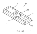
- FIG. 5A, 5B an additional alternative embodiment of the present invention is shown in which a repeater unit 10 is incorporated within a fluorescent light fixture 13 that includes a ballast 9.
- This embodiment includes the same components and functionality as the Figure 1 embodiment including the repeater board 26, the antenna 24, and the first power supply 22 and other circuitry (not shown) but described functionally in Figures 2A and 2B.
- the major difference from the Figure 1 embodiment is that this alternative embodiment repeater unit 10 plus a first fluorescent light bulb 21 replaces a standard fluorescent light bulb.
- the repeater unit-10 includes a plug 19 that fits into a fluorescent light fixture socket (not shown) and is mechanically adapted to accept a first fluorescent bulb 21 so that the functionality of the fluorescent light fixture 13 is maintained.
- a second fluorescent bulb 15 also fits into the fluorescent light fixture 13 to permit more light.
- the repeater described in the next two paragraphs is not hard-wired, but rather plugs into an existing socket. Additionally, the repeaters described below include sockets for use with other electrical appliances in the same way that the first embodiment includes sockets for the light bulb that was removed to install the repeater. Finally, installation should be described in the same way installation was described for the first embodiment.
- a service outlet 62 is an electric outlet but may be any outlet that provides a source of electrical energy.
- a service outlet repeater unit 60 (not shown) is installed into the plastic housing 58.
- the service outlet repeater unit 60 (not shown) includes outlet repeater antennas 56 to receive and to transmit electric signals to and from repeaters, base stations, or other destinations such as a centrally located data center.
- this alternative embodiment is plugged into an existing electrical outlet or socket instead of inserted into an electrical light receptacle.
- FIG. 7 is a partly sectional, partly phantom view of the service outlet 62 of Figure 6.
- This alternative embodiment houses the service outlet repeater unit 60 within the service outlet 62 has the same functional aspects and same basic component building blocks as shown in Figures 2A and 2B.
- the service outlet repeater unit 60 comprises the following components: the plastic housing 58 (as shown in Figure 3); the service outlet 62 (functionally equivalent to the second power supply 48); outlet batteries 64 (functionally equivalent to the first power supply 22); a transceiver/repeater printed circuit board 66 (functionally equivalent to the RF circuit board 26); and outlet repeater service antennas 56 (functionally equivalent to the antenna 24).
- the service outlet repeater unit 60 draws power from the outlet batteries 64 during periods of time the service outlet 62 is not powered, e.g., blown fuse or when power is unavailable.
- the service outlet repeater unit 60 recharges the outlet batteries 64 and powers the service outlet repeater unit 60 during periods when the service outlet 62 is energized, i.e., powered-on.
- the choice for components are only exemplary in nature including: the plastic housing which may be any housing unit, a service outlet which may be any wired electrical receptacle, and the outlet batteries, which may be any rechargeable storage device. As such, these possible variations in components are included within the scope of this invention.
- a repeater unit may further be hard-wired into an existing electrical outlet.
- the component functionality is the same as discussed in the above embodiments, however, the installation would be different such as requiring partial or full removal of existing wall outlet plug, and electrical connection of a repeater unit to existing wires disconnected from a existing wall outlet and mounting to the surface associated with an existing wall outlet.
- a repeater unit is adapted to replace a building accouterment while maintaining said functionality of said building accouterment.
- the building accouterment is by way of example, a ceiling tile, a heating and ventilation and air conditioning (HVAC) grill, a ceiling speaker, a ceiling speaker tile, and a speaker grill or speaker attached to the wall of the building or the like.
- HVAC heating and ventilation and air conditioning
- a first power supply may be the sole source of electrical power for the repeater unit.
- both a first power supply and a second power supply may supply power to the repeater unit.
- the installation would be different than Figure 6 above, including removal of the building accouterment which is well known in the art, and installation of the repeater unit adapted to replace a building accouterment.
Abstract
Description
- The present invention relates to radio frequency wireless signaling systems, and more particularly to an improved repeater system which can be incorporated into electrically powered fixtures for supplying power to common electrical devices such as light bulbs, fluorescent tubes, circuit outlets and switches, or other electrical appliances. More particularly, the present invention relates to a repeater electrically coupled to an electrical fixture, and including a transceiver unit electrically connected to a first power supply, having a housing unit that is adapted to mechanically cooperate with an electrical fixture, whereby the repeater unit provides continuous operation even when electrical power from the electrical fixture is unavailable.
- Known systems employ remote transducers to signal various observations to a base station, but may lack power to reach the destination, such as a centrally located station. One or more repeaters intercept the signal, amplify it and retransmit it until the destination is reached. For example, a transducer at a remote location can detect and signal smoke, temperature, humidity, wind speed and other important environmental parameters. Other transducers can provide signals representative of the state or the physical condition of an object or physical location.
- Most buildings, including dwellings, are now equipped with transducers or sensors combined in a detector to monitor the performance and efficiency of heating, ventilation and air conditioning equipment. Other sensors incorporated in a smoke detector are used to monitor atmospheric parameters such as smoke level or temperature condition that warn of an fire. Still other sensors are used to signal a security breach, or other hazardous or dangerous condition.
- For the most part, such detectors issue an audible or visible alarm, but not necessarily a signal that can be received in a centrally located station where someone can call for assistance. A repeater circuit associated with a transducer such as a smoke detectors or other fire sensors, if equipped with a wireless transmitter to broadcast a signal that includes the location of the sensor and the conditions being monitored could, if operated in conjunction with repeaters between the sensor and the base station, alert the base station to the change in conditions that can be interpreted as a fire.
- But providing a power supply to such a repeater unit is troublesome because electrical outlets may not be readily available. Usually, within relatively close range of a detector are installed powered devices such as light fixtures or power outlets to which power is applied from a central location for predetermined and finite periods of time. For example, in a large residential complex such as an apartment building, area lights are illuminated during the hours of darkness and are not powered during the times when adequate ambient light is provided from natural sources. Thus, there is a need for a repeater unit that is suitable to be installed in an existing electrical receptacle so that signals from nearby detectors that need monitoring may be stored, amplified, and broadcast to a centrally located station and that provides other advantages and features over present repeater units, such as compactness and continuous operation even when electrical power from a receptacle is unavailable.
- The present invention relates to a repeater unit that are proximal to sensors to receive and retransmit signals, including circuits that power the transmit and the receive functions. Also present are circuits that respond to the intermittent provision of electrical power to recharge batteries which normally power the system when electrical power is absent. The frequent recharging of the batteries facilitate uninterrupted communication between the sensors and the base station.
- In a preferred embodiment, the repeater unit is designed to mate with an existing light bulb socket so that it can be interposed between a light bulb and the socket. Since the repeater unit also includes a light bulb socket, that must be done to install the repeater unit is remove the light bulb from the socket, insert the repeater unit and return the light bulb to the socket of the repeater unit. During daylight hours, while the light bulb is not being powered-on, the rechargeable batteries permit operation of the repeater unit to relay sensor information to the central location such as a base station. In the evening, when the lights are powered-on, the repeater unit is also powered-on and the batteries are recharged. Thereby, the repeater unit provides continuous operation even when electrical power from a light bulb socket or other receptacle is unavailable.
- In other embodiments, the repeater unit is installed in a fluorescent light fixture and connected to the power lines. In additional embodiments, the repeater unit could be installed in EXIT signs or even switches. In yet other embodiments, the repeater unit can be incorporated in outlet receptacles where the power always is present to the unit and the batteries provide a back up in the event of a loss of power to the premises.
- For a better understanding of the present invention, reference is made to the below referenced accompanying drawings. Reference number refer to the same or the equivalent parts of the present invention throughout the several figures of the drawings.
- Figure 1 is a side, partially sectioned view of repeater incorporated in a lamp base according to the present invention;
- Figures 2A, 2B are block diagrams of the circuits of the embodiment of Figure 1;
- Figure 3 is an alternative embodiment of the present invention in which a repeater unit incorporates into an R30 light fixture.
- Figure 4A is another alternative embodiment of the present invention in which a repeater unit is incorporated within a light bulb.
- Figure 4B is another alternative embodiment of the present invention in which a repeater unit is a-light-bulb shaped fixture that cooperates with a light bulb.
- Figures 5A and 5B is an alternative embodiment of the present invention in which a repeater unit is incorporated within a fluorescent light fixture.
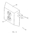
- Figure 6 is a perspective view of an alternative embodiment of the present invention in which a repeater is incorporated into an electrical outlet; and
- Figure 7 partly sectional, partly phantom view of outlet of Figure 6.
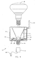
- Referring to Figure 1, there is shown one preferred embodiment of the present invention in which a repeater unit is adapted to install into an
electrical light socket 14. In Figure 1, arepeater unit 10 comprises ahosing unit 12 fitted with afirst mating structure 16 which is adapted to mechanically and to electrically cooperate with theelectrical light socket 14. Therepeater unit 10 further comprises afirst power supply 22 to provide power to therepeater unit 10. In one preferred embodiment, theelectrical light socket 14 is a candelabra socket and thefirst mating structure 16 is adapted to fit the candelabra socket. It should be noted that theelectric light socket 14 is electrically connected to thesecond power supply 48 that provides electrical power. In one preferred embodiment, theelectrical light socket 14 maintains its existing functionality whenrepeater unit 10 is installed. Further, in this embodiment, thefirst mating structure 16 is a standard candelabra base that mechanically and electrically cooperates with the candelabra socket. Additionally, it should be noted that thefirst mating structure 16 may be any mechanical structure that mates with an electrical receptacle. Electrical light socket 1:4 may be an electrical outlet, an electrical receptacle, an electrical fixture, a power supply fixture, an existing fixture, an electrically powered fixture, a fixture or a fixture that is associated with asecond power supply 48. - The
housing unit 12 may further comprise aheat shield 11. Thehead shield 11 acts as a reflector for light when alight bulb 18 is powered-on. However, it should be noted that even though thelight bulb 18 is depicted in the figure as a incandescent flood light bulb, a repeater according to the present invention is designed to cooperate with other light fixtures such as a fluorescent light, a fluorescent tube, a neon light, a neon tube, other light sources or common electrical devices come within the spirit and the scope of the present invention. In addition, thehousing unit 12 comprises a housinginterior walls 20, wherein thefirst power supply 22 is mounted between thehousing interior wall 20 and theheat shield 11, thefirst power supply 22. Mounted to thehousing unit 12 is anantenna 24 which transmits and receives wireless signals: Theantenna 24 is depicted as a monopole antenna but may be any device that will receive and transmit wireless signals. Arepeater circuit board 26 is located at the base of the housing interior while asecond circuit board 34 is connected to asecond mating structure 17 that is adapted to insert a light source such as alight bulb 18. Further, thesecond mating structure 17 is electrically connected to thesecond power source 48. In one preferred embodiment, therepeater circuit board 26 comprises atransceiver circuit 28. In addition, thefirst power supply 22, which may include a rechargeable power storage module, comprising a rechargeable power storage cell and a power recharger, to provide energizing power to set the desired operating point for thetransceiver circuit 28. - Referring to Figures 2A and 2B, block diagrams of the
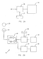
repeater circuit board 26 is shown. In one preferred embodiment, thefirst power supply 22 is a rechargeable battery module including arechargeable battery 27 and abattery charger 46. It should be noted that thefirst power supply 22 may be any electrical storage device such as a nickel cadmium battery, a lithium-ion battery, a rechargeable power storage module, or any device that provides electrical energy. It should also be noted that a power recharger may be any device that charges a rechargeable power storage cell such as a solar panel array, transformer, electrical circuit board or other electrical circuit. Thesecond power supply 48 is a source of energy from theelectrical light socket 14. The second power supply 48 furnishes electrical energy to thebattery charger 46. Thebattery charger 46, in turn, powers thetransceiver circuit 28 and recharges therechargeable battery 27 when power from thesecond power supply 48 is available, i.e., powered-on. When thesecond power supply 48 is not available, not being supplied, or powered-off to themating structure 16, thefirst power supply 22 powers therepeater unit 10. - The
repeater circuit board 26 further comprises a first system and a second system. The first system includes thetransceiver circuit 28, a receivedsignal strength indicator 31 and adisplay 38. The second system includes amicro-controller unit 40, amemory storage unit 32 and adata communication port 42. In one preferred embodiment, thetransceiver circuit 28 is a Texas Instruments, part No. TRF6901 RF transceiver circuit. However, thetransceiver circuit 28 may be any similar transmit/receive circuit that will receive and transmit electrical signals. In this embodiment, thetransceiver circuit 28 receives at least one electrical signal from theantenna 24. The signal is as a Radio Frequency (RF), a microwave or millimeter wave signal. The signal originates ata-transducer 23, which may by example be located in a building, such as an apartment or office building, which measures environmental parameters such as smoke index, particulate matter, moisture, humidity, pressure or temperature. By way of other examples, thetransducer 23 may be located in an exit sign, a fire alarm, an air-conditioning unit, or other locations where a user desires to monitor the environmental parameters and to send this information to another location, such as a repeater or a base station. - After the
transceiver circuit 28 receives and processes the signal representing the measured environmental parameter, the signal is electrically coupled to themicro-controller 40. In one preferred embodiment, the micro-controller is a Xilinix, Part No. XE2S 100E. Generally, the micro-controller evaluates the signal, then categorizes and maps the signal into representative values for storage within thememory storage unit 32. In one preferred embodiment, thememory storage unit 32 is a Microchip, Part No. #93AA56A, but, other memory storage devices may be substituted and are also included within the scope of this invention. Following, themicro-controller 40 may send the representative values back through thetransceiver circuit 26 for re-transmission through theantenna 24 to a centrally located station, a centralized database station, another repeater unit, or other destination. - The
data communication port 42 provides control and data signals to themicro-controller unit 40. Such control and data signals used to program, to reprogram, to enter data, or to remove data which may be stored internally within themicro-controller unit 40 or externally within thememory storage unit 32. In one mode, the control and data signals program themicro-controller unit 40 to determine which of the signals received by theantenna 24 is to be processed further by thetransceiver circuit 28. In another mode, the control and data signals program themicro-controller 32 to store such signals in thememory storage unit 32. In another mode, the control signals program themicro-controller unit 32 to select which of the stored signals is to be retrieved from thememory storage unit 32, and which of them are to be transmitted from thetransceiver unit 28 through theantenna 24, to the next repeater unit, the base station, centrally located station, or centralized database station. The following paragraphs address alternative component packaging for a repeater unit of the present invention. The repeaters described in the following paragraphs are not hard-wired, but rather plug into an existing socket. Additionally, the repeaters described below may include sockets for use with other electrical appliances in the-same-way that-the first embodiment includes sockets for the light bulb that was removed to install the repeater. - Referring to Figure 3, an alternative embodiment of the present invention is shown, in which a
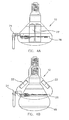
repeater unit 10 allows insertion of an R30 light bulb and fits into an R30 light fixture. This embodiment includes the same components and functionality as the Figure 1 embodiment including therepeater board 26, theantenna 24 and thefirst power supply 22 and other circuitry (not shown) but described functionally in Figures 2A and 2B. The major difference from the Figure 1 embodiment is that this alternative embodiment fits into an R30 light fixture. - Referring to Figure 4A, another alternative embodiment of the present invention is shown, in which a
repeater unit 10 is packaged within a light bulb. This embodiment includes the same components and functionality as the Figure 1 embodiment including therepeater board 26, theantenna 24, and thefirst power supply 22 and other circuitry (not shown) but described functionally in Figures 2A and 2B. The major difference from the Figure 1 embodiment is that in this alternative embodiment, therepeater unit 10 looks like a light bulb. - Referring to Figure 4B, another alternative embodiment of the present invention is shown, in which a
repeater unit 10 is a light bulb shaped fixture that cooperates with another a light bulb. This embodiment includes the same components and functionality as the Figure 1 embodiment including therepeater board 26, theantenna 24, and thefirst power supply 22 and other circuitry (not shown) but described functionally in Figures 2A and 2B. The major difference from the Figure 1 embodiment is that in this alternative embodiment, therepeater unit 10 looks like a light bulb and cooperates with another light bulb. - Referring to Figures 5A, 5B, an additional alternative embodiment of the present invention is shown in which a
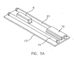
repeater unit 10 is incorporated within afluorescent light fixture 13 that includes a ballast 9. This embodiment includes the same components and functionality as the Figure 1 embodiment including therepeater board 26, theantenna 24, and thefirst power supply 22 and other circuitry (not shown) but described functionally in Figures 2A and 2B. The major difference from the Figure 1 embodiment is that this alternativeembodiment repeater unit 10 plus a firstfluorescent light bulb 21 replaces a standard fluorescent light bulb.--The repeater unit-10 includes aplug 19 that fits into a fluorescent light fixture socket (not shown) and is mechanically adapted to accept a firstfluorescent bulb 21 so that the functionality of thefluorescent light fixture 13 is maintained. Moreover, a secondfluorescent bulb 15 also fits into thefluorescent light fixture 13 to permit more light. The repeater described in the next two paragraphs is not hard-wired, but rather plugs into an existing socket. Additionally, the repeaters described below include sockets for use with other electrical appliances in the same way that the first embodiment includes sockets for the light bulb that was removed to install the repeater. Finally, installation should be described in the same way installation was described for the first embodiment. - Referring to Figure 6, a perspective view is shown of an alternative embodiment of the present invention in which a repeater is incorporated into a
service outlet 62. Aservice outlet 62 is an electric outlet but may be any outlet that provides a source of electrical energy. In particular, a service outlet repeater unit 60 (not shown) is installed into theplastic housing 58. Further, the service outlet repeater unit 60 (not shown) includesoutlet repeater antennas 56 to receive and to transmit electric signals to and from repeaters, base stations, or other destinations such as a centrally located data center. However, the major difference from other preferred embodiments discussed elsewhere in this specification is that this alternative embodiment is plugged into an existing electrical outlet or socket instead of inserted into an electrical light receptacle. - Referring to Figure 7 is a partly sectional, partly phantom view of the
service outlet 62 of Figure 6. This alternative embodiment houses the serviceoutlet repeater unit 60 within theservice outlet 62 has the same functional aspects and same basic component building blocks as shown in Figures 2A and 2B. In particular, the serviceoutlet repeater unit 60 comprises the following components: the plastic housing 58 (as shown in Figure 3); the service outlet 62 (functionally equivalent to the second power supply 48); outlet batteries 64 (functionally equivalent to the first power supply 22); a transceiver/repeater printed circuit board 66 (functionally equivalent to the RF circuit board 26); and outlet repeater service antennas 56 (functionally equivalent to the antenna 24). The serviceoutlet repeater unit 60 draws power from theoutlet batteries 64 during periods of time theservice outlet 62 is not powered, e.g., blown fuse or when power is unavailable. The serviceoutlet repeater unit 60 recharges theoutlet batteries 64 and powers the serviceoutlet repeater unit 60 during periods when theservice outlet 62 is energized, i.e., powered-on. It should be noticed that the choice for components are only exemplary in nature including: the plastic housing which may be any housing unit, a service outlet which may be any wired electrical receptacle, and the outlet batteries, which may be any rechargeable storage device. As such, these possible variations in components are included within the scope of this invention. - Further, in another embodiment of Figure 6, a repeater unit may further be hard-wired into an existing electrical outlet. In this embodiment, the component functionality is the same as discussed in the above embodiments, however, the installation would be different such as requiring partial or full removal of existing wall outlet plug, and electrical connection of a repeater unit to existing wires disconnected from a existing wall outlet and mounting to the surface associated with an existing wall outlet.
- Further, in another embodiment of Figure 6, a repeater unit is adapted to replace a building accouterment while maintaining said functionality of said building accouterment. The building accouterment is by way of example, a ceiling tile, a heating and ventilation and air conditioning (HVAC) grill, a ceiling speaker, a ceiling speaker tile, and a speaker grill or speaker attached to the wall of the building or the like. In this embodiment, a first power supply may be the sole source of electrical power for the repeater unit. An alternative of this embodiment, both a first power supply and a second power supply may supply power to the repeater unit. Further, in this embodiment, the installation would be different than Figure 6 above, including removal of the building accouterment which is well known in the art, and installation of the repeater unit adapted to replace a building accouterment.
- Information as herein shown and described in detail is fully capable of attaining the above-described object of the invention, the present preferred embodiment of the invention, and is, thus, representative of the subject matter which is broadly contemplated by the present invention. The scope of the present invention fully encompasses other embodiments which may become obvious to those skilled in the art, and is to be limited, accordingly, by nothing other than the appended claims, wherein reference to an element in the singular is not intended to mean "one and only one" unless explicitly so stated, but rather "one or more." All structural and functional equivalents to the elements of the above-described preferred embodiment and additional embodiments that are known to those of ordinary skill in the art are hereby expressly incorporated by reference and are intended to be encompassed by the present claims.
- Moreover, no requirement exists for a device or method to address each and every problem sought to be resolved by the present invention, for such to be encompassed by the present claim. Furthermore, no element, component, or method step in the present disclosure is intended to be dedicated to the public regardless of whether the element, component, or method step is explicitly recited in the claims. However, one skilled in the art should recognize that various changes and modifications in form and material details may be made without departing from the spirit and scope of the inventiveness as set forth in the appended claims. No claim herein is to be construed under the provisions of 35 U.S.C. § 112, sixth paragraph, unless the element is expressly recited using the phrase "means for."
Claims (35)
- A repeater, comprising:a transceiver unit;a rechargeable power supply electrically provided to said transceiver unit; anda housing unit for housing said transceiver and said rechargeable power supply;said housing including a lamp base, wherein an electrical connection is provided from said lamp base to a light socket such that said light socket receives electrical power from said lamp base, said light socket disposed at a base of cavity in said housing, said cavity configured to receive at least a portion of a light bulb, said housing unit configured to reduce a distance between said lamp base and said light socket by disposing at least a portion of said rechargeable power supply beside said cavity.
- The repeater of Claim 1, wherein said rechargeable power supply is provided to said lamp base.
- The repeater of Claim 1, further comprising a heat shield disposed in said cavity.
- The repeater of Claim 1, wherein said rechargeable power supply comprises one or more rechargeable batteries.
- The repeater of Claim 1, wherein a shape of said housing is substantially conformal to at least a portion of a light bulb.
- The repeater of Claim 1, wherein said transceiver is powered by electrical power from said lamp base when said lamp base receives electrical power.
- The repeater of Claim 1, wherein said transceiver is powered by electrical power from said rechargeable power supply when electrical power is not available from said lamp base.
- The repeater of Claim 1, wherein said rechargeable power supply is recharged by at least a portion of electrical power provided to said lamp base.
- The repeater of Claim 1, wherein said transceiver unit receives a signal from at least one transducer and re-transmits said signal to a base station.
- The repeater of Claim 1, wherein said lamp base comprises a candelabra lamp base.
- The repeater of Claim 1, wherein said cavity is configured to receive at least a portion of an R30 type bulb.
- A repeater, comprising:a transceiver unit;a rechargeable power supply electrically provided to said transceiver unit; anda housing unit for housing said transceiver and said rechargeable power supply, said housing including at least one standard electrical power plug configured to plug into a standard wall outlet, wherein an electrical connection is provided from said at least one plug to at least one standard electrical socket, and wherein said rechargeable power supply is provided to said plug.
- The repeater of Claim 12, wherein said rechargeable power supply comprises one or more rechargeable batteries.
- The repeater of Claim 12, wherein said transceiver is powered by electrical power from said plug when said plug receives electrical power.
- The repeater of Claim 12, wherein said transceiver is powered by electrical power from said rechargeable power supply when electrical power is not available from said plug.
- The repeater of Claim 12, wherein said rechargeable power supply is recharged by at least a portion of electrical power provided to said plug.
- The repeater of Claim 12, wherein said transceiver unit receives a signal from at least one transducer and re-transmits said signal to a base station.
- A repeater unit for mounting to electrically powered fixtures used for providing power to common electrical devices, while maintaining functionality of said fixtures, said repeater unit comprising:a transceiver unit;a first power supply electrically coupled to said transceiver unit; anda housing unit for housing the transceiver and first power supply, and for mechanically cooperating with said electrically powered fixture, andsaid housing unit mechanically cooperates with said electrically powered fixture, and wherein said first power supply also being electrically coupled to said electric power associated with said electrically powered fixture.
- A repeater unit which replaces a building accouterment, which comprises:a transceiver for receiving and re-transmitting a signal;a first power supply electrically connected to said transceiver unit; anda housing unit for housing the transceiver and power supply,whereby said housing unit is adapted to replace said building accouterment while maintaining functionality of said building accouterment.
- A method for replaying a transducer signal to a base station comprising:housing a transceiver and first power supply in a housing having mating structure for mounting to existing electrically powered fixtures used for providing power to common electrical devices;mechanically connecting the housing unit to said existing electrically powered fixture; andelectrically connected the transceiver and first power supply to a second power supply associated with said existing electrically powered fixture;receiving a signal;transmitting a signal;when power is available from the second power supply, providing power to said transceiver circuit from said power supply, and for recharging the first power supply; andwhen power is not available from said second power supply, providing said power to said transceiver circuit from said first power supply.
- A repeater unit in accordance with Claim 18, wherein said first power supply includes a rechargeable power storage module, said module being recharged by said electrical power when supplied to said electrically powered fixture.
- A repeater unit in accordance with Claim 18, wherein said first power supply includes a rechargeable power storage cell and a power charger, said power charger recharging said rechargeable power storage cell when electric power is supplied to said electrically powered fixture.
- A repeater unit in accordance with Claim 18, when said housing unit further includes mating structure for providing power to said common electrical devices.
- A repeater unit in accordance with Claim 18, wherein said mating structure further comprises a first mating structure for mechanically installing into said electrically powered fixture.
- A repeater unit in accordance with Claim 18, wherein said mating structure further comprises a second mating structure for maintaining said electrically powered fixture functionality.
- A repeater unit in accordance with Claim 18, wherein said first power supply is powered-on when said electrically powered fixture is powered-off.
- A repeater unit in accordance with Claim 18, wherein said first power supply is powered-off when said electrically powered fixture is powered-on.
- A repeater unit in accordance with Claim 18, wherein said first power supply is being recharged when said existing electrical fixture is powered-on.
- A repeater unit in accordance with Claim 18, wherein said first power supply is adapted to provide continuous power to said electrically powered fixture even when electrical power is unavailable to the fixtures.
- A repeater unit in accordance with Claim 18, wherein said electrically powered fixture is located in an apartment building and a transducer sends signal to said electrically powered fixture.
- A repeater unit in accordance with Claim 18, wherein said transceiver unit receives a signal from at least one transducer and re-transmits said signal to a base station.
- A repeater unit in accordance with Claim 18, wherein said housing unit is adapted to insert into an exit sign.
- A repeater unit in accordance with Claim 31, wherein said building accoutrement is a ceiling tile.
- A repeater unit in accordance with Claim 31, wherein said building accouterment is heating ventilation and air conditioning (HVAC) grill.
- A repeater unit in accordance with Claim 31, wherein said building accouterment is a ceiling speaker.
Applications Claiming Priority (2)
| Application Number | Priority Date | Filing Date | Title |
|---|---|---|---|
| US10/718,374 US7199701B2 (en) | 2003-11-19 | 2003-11-19 | Repeater unit |
| EP04795153A EP1690439A1 (en) | 2003-11-19 | 2004-10-14 | Repeater unit |
Related Parent Applications (1)
| Application Number | Title | Priority Date | Filing Date |
|---|---|---|---|
| EP04795153A Division EP1690439A1 (en) | 2003-11-19 | 2004-10-14 | Repeater unit |
Publications (2)
| Publication Number | Publication Date |
|---|---|
| EP1909540A2 true EP1909540A2 (en) | 2008-04-09 |
| EP1909540A3 EP1909540A3 (en) | 2009-03-11 |
Family
ID=34574668
Family Applications (2)
| Application Number | Title | Priority Date | Filing Date |
|---|---|---|---|
| EP04795153A Withdrawn EP1690439A1 (en) | 2003-11-19 | 2004-10-14 | Repeater unit |
| EP07017386A Withdrawn EP1909540A3 (en) | 2003-11-19 | 2004-10-14 | Repeater unit |
Family Applications Before (1)
| Application Number | Title | Priority Date | Filing Date |
|---|---|---|---|
| EP04795153A Withdrawn EP1690439A1 (en) | 2003-11-19 | 2004-10-14 | Repeater unit |
Country Status (6)
| Country | Link |
|---|---|
| US (3) | US7199701B2 (en) |
| EP (2) | EP1690439A1 (en) |
| JP (1) | JP2007511976A (en) |
| AU (1) | AU2004297935A1 (en) |
| CA (1) | CA2545421A1 (en) |
| WO (1) | WO2005057989A1 (en) |
Cited By (3)
| Publication number | Priority date | Publication date | Assignee | Title |
|---|---|---|---|---|
| EP2309826A1 (en) * | 2009-09-26 | 2011-04-13 | WTS Kereskedelmi és Szolgáltató Kft. | Illumination device |
| EP2439709A1 (en) * | 2010-10-05 | 2012-04-11 | Cooper Security Limited | Alarm system power supply housing that has integrated signal transmitting means |
| WO2014041496A1 (en) * | 2012-09-12 | 2014-03-20 | Ariel - University Research And Development Company, Ltd. | Light fixture connectable device useful for establishing a network infrastructure |
Families Citing this family (20)
| Publication number | Priority date | Publication date | Assignee | Title |
|---|---|---|---|---|
| US20050164630A1 (en) * | 2003-11-19 | 2005-07-28 | Lawrence Kates | Repeater unit with flourescent ballast |
| US7199701B2 (en) * | 2003-11-19 | 2007-04-03 | Lawrence Kates | Repeater unit |
| US7522876B1 (en) * | 2004-04-21 | 2009-04-21 | Phc Llc | Distributed access gateway and wireless router pods and public safety communications infrastructure incorporating the same |
| GB2424800B (en) * | 2005-04-01 | 2008-02-13 | Toshiba Res Europ Ltd | Wireless communications device |
| ITTV20050079A1 (en) | 2005-06-07 | 2006-12-08 | Codem Music Srl | RECEIVER DEVICE FOR DIGITAL TRANSMISSION PROTOCOL SIGNALS, PARTICULARLY FOR LIGHTING EQUIPMENT. |
| JP4653581B2 (en) * | 2005-07-21 | 2011-03-16 | 株式会社東芝 | Retransmission antenna and retransmission antenna with amplifier |
| DE202005019369U1 (en) * | 2005-12-02 | 2006-02-16 | Arnold & Richter Cine Technik Gmbh & Co. Betriebs Kg | Device for receiving and electrical contacting of a light source in a headlight |
| US20100296685A1 (en) * | 2009-05-20 | 2010-11-25 | Lake Shore Studios, Inc. | Adapter and electronic devices for recessed light socket |
| US8933811B2 (en) * | 2009-10-05 | 2015-01-13 | Cavius Aps | Smoke alarm |
| JP2012142111A (en) * | 2010-12-28 | 2012-07-26 | Koito Mfg Co Ltd | Lighting device for discharge lamp |
| US8774707B2 (en) * | 2011-12-16 | 2014-07-08 | Silver Spring Networks, Inc. | Utility grid wireless node with powered emergency device |
| TWM427521U (en) * | 2011-12-23 | 2012-04-21 | Tuton Technology Co Ltd | Lamp holder module with embedded signal booster |
| EP2991242A1 (en) * | 2014-08-27 | 2016-03-02 | Fraunhofer-Gesellschaft zur Förderung der angewandten Forschung e.V. | Controller for a SUDA system |
| JP5944971B2 (en) * | 2014-10-24 | 2016-07-05 | ホーチキ株式会社 | Emergency lighting system |
| JP6825421B2 (en) * | 2016-03-02 | 2021-02-03 | 株式会社リコー | Remote monitoring system, information processing device, program and adapter device |
| US10651616B2 (en) | 2016-03-29 | 2020-05-12 | Anyware Solutions Aps | Light socket adapter with ambient sensoring means |
| US9848480B1 (en) | 2016-06-14 | 2017-12-19 | Honeywell International Inc. | Lightbulb in a fixture having a configuration memory |
| USD848405S1 (en) | 2017-02-06 | 2019-05-14 | Hunter Douglas Inc. | Wireless repeater |
| US10986719B2 (en) | 2018-01-05 | 2021-04-20 | Hampton Products International Corporation | Wireless layered security system |
| CN213453436U (en) * | 2020-07-14 | 2021-06-15 | 深圳市里阳电子有限公司 | Bulb component of electronic candle wick |
Citations (8)
| Publication number | Priority date | Publication date | Assignee | Title |
|---|---|---|---|---|
| EP0346152A2 (en) * | 1988-06-10 | 1989-12-13 | James Cairney | Smoke detector devices and detector circuit |
| US5432500A (en) * | 1993-10-25 | 1995-07-11 | Scripps International, Ltd. | Overhead detector and light assembly with remote control |
| JPH11136191A (en) * | 1997-10-27 | 1999-05-21 | Toto Ltd | Outlet adaptor type radio repeater, radio communication system provided with the repeater, and health management network system |
| WO2000021047A1 (en) * | 1998-10-07 | 2000-04-13 | Runner & Sprue Limited | Alarm |
| US20020197963A1 (en) * | 2001-06-01 | 2002-12-26 | Deutsches Zentrum Fur Luft-Und Raumfahrt E. V. | Data communications system including a local beacon |
| US20030016129A1 (en) * | 2001-07-17 | 2003-01-23 | Menard Raymond J. | Electrical power control and sensor module for a wireless system |
| US20030031310A1 (en) * | 2001-05-31 | 2003-02-13 | Damon Bruccoleri | Plug-in single phase power line signal repeater with low voltage bus |
| US20030199247A1 (en) * | 2002-04-18 | 2003-10-23 | International Business Machines Corporation | Light socket wireless repeater and controller |
Family Cites Families (10)
| Publication number | Priority date | Publication date | Assignee | Title |
|---|---|---|---|---|
| WO1985004769A1 (en) | 1984-04-09 | 1985-10-24 | Nigg Juerg | Process for releasibly connecting electric lighting apparatuses, adapter respectively ballast and circuit with a high frequency generator |
| US4600968A (en) * | 1984-11-13 | 1986-07-15 | Fuji Electric Co., Ltd. | Semiconductor device package having regions of different thermal properties |
| DE9206294U1 (en) | 1992-05-11 | 1992-07-02 | Patent-Treuhand-Gesellschaft Fuer Elektrische Gluehlampen Mbh, 8000 Muenchen, De | |
| DE19501417A1 (en) | 1995-01-19 | 1996-07-25 | Holzer Walter | Compact gas-discharge lamp contact system |
| US5950149A (en) * | 1997-06-30 | 1999-09-07 | Chrysler Corporation | Method for testing vehicle electrical system during manufacturing |
| US6400968B1 (en) | 1998-05-04 | 2002-06-04 | Conexant Systems, Inc. | System and method for extending the range of a base unit |
| US6914533B2 (en) * | 1998-06-22 | 2005-07-05 | Statsignal Ipc Llc | System and method for accessing residential monitoring devices |
| US7042170B2 (en) | 2003-05-31 | 2006-05-09 | Lights Of America, Inc. | Digital ballast |
| US20050164630A1 (en) * | 2003-11-19 | 2005-07-28 | Lawrence Kates | Repeater unit with flourescent ballast |
| US7199701B2 (en) * | 2003-11-19 | 2007-04-03 | Lawrence Kates | Repeater unit |
-
2003
- 2003-11-19 US US10/718,374 patent/US7199701B2/en not_active Expired - Fee Related
-
2004
- 2004-10-14 EP EP04795153A patent/EP1690439A1/en not_active Withdrawn
- 2004-10-14 CA CA002545421A patent/CA2545421A1/en not_active Abandoned
- 2004-10-14 AU AU2004297935A patent/AU2004297935A1/en not_active Abandoned
- 2004-10-14 WO PCT/US2004/033953 patent/WO2005057989A1/en active Application Filing
- 2004-10-14 JP JP2006541160A patent/JP2007511976A/en active Pending
- 2004-10-14 EP EP07017386A patent/EP1909540A3/en not_active Withdrawn
-
2006
- 2006-05-02 US US11/415,767 patent/US7403097B2/en not_active Expired - Fee Related
-
2008
- 2008-07-15 US US12/173,610 patent/US20080318521A1/en not_active Abandoned
Patent Citations (8)
| Publication number | Priority date | Publication date | Assignee | Title |
|---|---|---|---|---|
| EP0346152A2 (en) * | 1988-06-10 | 1989-12-13 | James Cairney | Smoke detector devices and detector circuit |
| US5432500A (en) * | 1993-10-25 | 1995-07-11 | Scripps International, Ltd. | Overhead detector and light assembly with remote control |
| JPH11136191A (en) * | 1997-10-27 | 1999-05-21 | Toto Ltd | Outlet adaptor type radio repeater, radio communication system provided with the repeater, and health management network system |
| WO2000021047A1 (en) * | 1998-10-07 | 2000-04-13 | Runner & Sprue Limited | Alarm |
| US20030031310A1 (en) * | 2001-05-31 | 2003-02-13 | Damon Bruccoleri | Plug-in single phase power line signal repeater with low voltage bus |
| US20020197963A1 (en) * | 2001-06-01 | 2002-12-26 | Deutsches Zentrum Fur Luft-Und Raumfahrt E. V. | Data communications system including a local beacon |
| US20030016129A1 (en) * | 2001-07-17 | 2003-01-23 | Menard Raymond J. | Electrical power control and sensor module for a wireless system |
| US20030199247A1 (en) * | 2002-04-18 | 2003-10-23 | International Business Machines Corporation | Light socket wireless repeater and controller |
Cited By (4)
| Publication number | Priority date | Publication date | Assignee | Title |
|---|---|---|---|---|
| EP2309826A1 (en) * | 2009-09-26 | 2011-04-13 | WTS Kereskedelmi és Szolgáltató Kft. | Illumination device |
| EP2439709A1 (en) * | 2010-10-05 | 2012-04-11 | Cooper Security Limited | Alarm system power supply housing that has integrated signal transmitting means |
| WO2014041496A1 (en) * | 2012-09-12 | 2014-03-20 | Ariel - University Research And Development Company, Ltd. | Light fixture connectable device useful for establishing a network infrastructure |
| US9374875B2 (en) | 2012-09-12 | 2016-06-21 | Ariel-University Research And Development Company Ltd. | Light fixture connectable device useful for establishing a network infrastructure |
Also Published As
| Publication number | Publication date |
|---|---|
| EP1909540A3 (en) | 2009-03-11 |
| US20050107033A1 (en) | 2005-05-19 |
| WO2005057989A1 (en) | 2005-06-23 |
| CA2545421A1 (en) | 2005-06-23 |
| US7199701B2 (en) | 2007-04-03 |
| AU2004297935A1 (en) | 2005-06-23 |
| US7403097B2 (en) | 2008-07-22 |
| JP2007511976A (en) | 2007-05-10 |
| US20060208877A1 (en) | 2006-09-21 |
| US20080318521A1 (en) | 2008-12-25 |
| EP1690439A1 (en) | 2006-08-16 |
Similar Documents
| Publication | Publication Date | Title |
|---|---|---|
| US7403097B2 (en) | Conformal repeater unit | |
| US7460006B2 (en) | Conformal repeater unit | |
| US8467734B2 (en) | Wireless transceiver within an electrical receptacle system | |
| CN107735920B (en) | Automation system for lighting control | |
| US20200056773A1 (en) | Connecting lighting to poles without tools | |
| US20060006817A1 (en) | AC powered self organizing wireless node | |
| EP1501060B1 (en) | A smoke alarm device | |
| AU2006100421A4 (en) | Repeater Unit | |
| EP3716240B1 (en) | Wireless communication terminal, fire alarm, and management system | |
| JP4722817B2 (en) | Lighting device and illuminance adjustment system | |
| JP2501926B2 (en) | Wireless alarm system | |
| CN214009043U (en) | Multifunctional emergency ceiling lamp | |
| IE84058B1 (en) | A smoke alarm device |
Legal Events
| Date | Code | Title | Description |
|---|---|---|---|
| PUAI | Public reference made under article 153(3) epc to a published international application that has entered the european phase |
Free format text: ORIGINAL CODE: 0009012 |
|
| 17P | Request for examination filed |
Effective date: 20070914 |
|
| AC | Divisional application: reference to earlier application |
Ref document number: 1690439 Country of ref document: EP Kind code of ref document: P |
|
| AK | Designated contracting states |
Kind code of ref document: A2 Designated state(s): AT BE BG CH CY CZ DE DK EE ES FI FR GB GR HU IE IT LI LU MC NL PL PT RO SE SI SK TR |
|
| PUAL | Search report despatched |
Free format text: ORIGINAL CODE: 0009013 |
|
| REG | Reference to a national code |
Ref country code: HK Ref legal event code: DE Ref document number: 1119015 Country of ref document: HK |
|
| AK | Designated contracting states |
Kind code of ref document: A3 Designated state(s): AT BE BG CH CY CZ DE DK EE ES FI FR GB GR HU IE IT LI LU MC NL PL PT RO SE SI SK TR |
|
| 17Q | First examination report despatched |
Effective date: 20091007 |
|
| AKX | Designation fees paid |
Designated state(s): AT BE BG CH CY CZ DE DK EE ES FI FR GB GR HU IE IT LI LU MC NL PL PT RO SE SI SK TR |
|
| STAA | Information on the status of an ep patent application or granted ep patent |
Free format text: STATUS: THE APPLICATION IS DEEMED TO BE WITHDRAWN |
|
| 18D | Application deemed to be withdrawn |
Effective date: 20100420 |
|
| REG | Reference to a national code |
Ref country code: HK Ref legal event code: WD Ref document number: 1119015 Country of ref document: HK |