EP1929901A1 - Heating device for seat - Google Patents
Heating device for seat Download PDFInfo
- Publication number
- EP1929901A1 EP1929901A1 EP06782658A EP06782658A EP1929901A1 EP 1929901 A1 EP1929901 A1 EP 1929901A1 EP 06782658 A EP06782658 A EP 06782658A EP 06782658 A EP06782658 A EP 06782658A EP 1929901 A1 EP1929901 A1 EP 1929901A1
- Authority
- EP
- European Patent Office
- Prior art keywords
- seat
- control circuit
- temperature control
- heating device
- detection element
- Prior art date
- Legal status (The legal status is an assumption and is not a legal conclusion. Google has not performed a legal analysis and makes no representation as to the accuracy of the status listed.)
- Granted
Links
- 238000010438 heat treatment Methods 0.000 title claims abstract description 125
- 238000001514 detection method Methods 0.000 claims abstract description 56
- 239000000126 substance Substances 0.000 claims abstract description 28
- 230000003014 reinforcing effect Effects 0.000 claims description 18
- 229920001169 thermoplastic Polymers 0.000 claims description 8
- 239000004416 thermosoftening plastic Substances 0.000 claims description 8
- 229910052751 metal Inorganic materials 0.000 claims description 5
- 239000002184 metal Substances 0.000 claims description 5
- 239000011888 foil Substances 0.000 claims description 4
- 239000012790 adhesive layer Substances 0.000 claims description 3
- 230000001747 exhibiting effect Effects 0.000 abstract description 4
- 239000000853 adhesive Substances 0.000 description 5
- 230000001070 adhesive effect Effects 0.000 description 5
- 238000004519 manufacturing process Methods 0.000 description 4
- 229920005989 resin Polymers 0.000 description 4
- 239000011347 resin Substances 0.000 description 4
- 230000003213 activating effect Effects 0.000 description 3
- 238000005452 bending Methods 0.000 description 3
- 239000010410 layer Substances 0.000 description 3
- 239000000463 material Substances 0.000 description 3
- 239000000843 powder Substances 0.000 description 3
- 239000002390 adhesive tape Substances 0.000 description 2
- 239000003795 chemical substances by application Substances 0.000 description 2
- 230000005494 condensation Effects 0.000 description 2
- 238000009833 condensation Methods 0.000 description 2
- 238000009413 insulation Methods 0.000 description 2
- 239000011368 organic material Substances 0.000 description 2
- 239000002245 particle Substances 0.000 description 2
- BASFCYQUMIYNBI-UHFFFAOYSA-N platinum Chemical compound [Pt] BASFCYQUMIYNBI-UHFFFAOYSA-N 0.000 description 2
- OKTJSMMVPCPJKN-UHFFFAOYSA-N Carbon Chemical compound [C] OKTJSMMVPCPJKN-UHFFFAOYSA-N 0.000 description 1
- 229920000049 Carbon (fiber) Polymers 0.000 description 1
- 229910052782 aluminium Inorganic materials 0.000 description 1
- XAGFODPZIPBFFR-UHFFFAOYSA-N aluminium Chemical compound [Al] XAGFODPZIPBFFR-UHFFFAOYSA-N 0.000 description 1
- 230000000386 athletic effect Effects 0.000 description 1
- 239000006229 carbon black Substances 0.000 description 1
- 239000004917 carbon fiber Substances 0.000 description 1
- 229920001940 conductive polymer Polymers 0.000 description 1
- 230000010485 coping Effects 0.000 description 1
- 238000004132 cross linking Methods 0.000 description 1
- 230000006866 deterioration Effects 0.000 description 1
- 230000000694 effects Effects 0.000 description 1
- 238000010894 electron beam technology Methods 0.000 description 1
- 230000005669 field effect Effects 0.000 description 1
- 229910002804 graphite Inorganic materials 0.000 description 1
- 239000010439 graphite Substances 0.000 description 1
- 230000009931 harmful effect Effects 0.000 description 1
- 230000013011 mating Effects 0.000 description 1
- 229910044991 metal oxide Inorganic materials 0.000 description 1
- 150000004706 metal oxides Chemical class 0.000 description 1
- VNWKTOKETHGBQD-UHFFFAOYSA-N methane Chemical compound C VNWKTOKETHGBQD-UHFFFAOYSA-N 0.000 description 1
- 238000000465 moulding Methods 0.000 description 1
- 229910052697 platinum Inorganic materials 0.000 description 1
- 229920005672 polyolefin resin Polymers 0.000 description 1
- 238000004382 potting Methods 0.000 description 1
- 238000007789 sealing Methods 0.000 description 1
- 229920001187 thermosetting polymer Polymers 0.000 description 1
Images


Classifications
-
- H—ELECTRICITY
- H05—ELECTRIC TECHNIQUES NOT OTHERWISE PROVIDED FOR
- H05B—ELECTRIC HEATING; ELECTRIC LIGHT SOURCES NOT OTHERWISE PROVIDED FOR; CIRCUIT ARRANGEMENTS FOR ELECTRIC LIGHT SOURCES, IN GENERAL
- H05B3/00—Ohmic-resistance heating
- H05B3/20—Heating elements having extended surface area substantially in a two-dimensional plane, e.g. plate-heater
- H05B3/34—Heating elements having extended surface area substantially in a two-dimensional plane, e.g. plate-heater flexible, e.g. heating nets or webs
-
- A—HUMAN NECESSITIES
- A47—FURNITURE; DOMESTIC ARTICLES OR APPLIANCES; COFFEE MILLS; SPICE MILLS; SUCTION CLEANERS IN GENERAL
- A47C—CHAIRS; SOFAS; BEDS
- A47C7/00—Parts, details, or accessories of chairs or stools
- A47C7/62—Accessories for chairs
- A47C7/72—Adaptations for incorporating lamps, radio sets, bars, telephones, ventilation, heating or cooling arrangements or the like
- A47C7/74—Adaptations for incorporating lamps, radio sets, bars, telephones, ventilation, heating or cooling arrangements or the like for ventilation, heating or cooling
-
- B—PERFORMING OPERATIONS; TRANSPORTING
- B60—VEHICLES IN GENERAL
- B60H—ARRANGEMENTS OF HEATING, COOLING, VENTILATING OR OTHER AIR-TREATING DEVICES SPECIALLY ADAPTED FOR PASSENGER OR GOODS SPACES OF VEHICLES
- B60H1/00—Heating, cooling or ventilating [HVAC] devices
- B60H1/22—Heating, cooling or ventilating [HVAC] devices the heat being derived otherwise than from the propulsion plant
-
- B—PERFORMING OPERATIONS; TRANSPORTING
- B60—VEHICLES IN GENERAL
- B60N—SEATS SPECIALLY ADAPTED FOR VEHICLES; VEHICLE PASSENGER ACCOMMODATION NOT OTHERWISE PROVIDED FOR
- B60N2/00—Seats specially adapted for vehicles; Arrangement or mounting of seats in vehicles
- B60N2/56—Heating or ventilating devices
- B60N2/5678—Heating or ventilating devices characterised by electrical systems
- B60N2/5685—Resistance
-
- H—ELECTRICITY
- H05—ELECTRIC TECHNIQUES NOT OTHERWISE PROVIDED FOR
- H05B—ELECTRIC HEATING; ELECTRIC LIGHT SOURCES NOT OTHERWISE PROVIDED FOR; CIRCUIT ARRANGEMENTS FOR ELECTRIC LIGHT SOURCES, IN GENERAL
- H05B3/00—Ohmic-resistance heating
- H05B3/02—Details
-
- H—ELECTRICITY
- H05—ELECTRIC TECHNIQUES NOT OTHERWISE PROVIDED FOR
- H05B—ELECTRIC HEATING; ELECTRIC LIGHT SOURCES NOT OTHERWISE PROVIDED FOR; CIRCUIT ARRANGEMENTS FOR ELECTRIC LIGHT SOURCES, IN GENERAL
- H05B2203/00—Aspects relating to Ohmic resistive heating covered by group H05B3/00
- H05B2203/002—Heaters using a particular layout for the resistive material or resistive elements
- H05B2203/003—Heaters using a particular layout for the resistive material or resistive elements using serpentine layout
-
- H—ELECTRICITY
- H05—ELECTRIC TECHNIQUES NOT OTHERWISE PROVIDED FOR
- H05B—ELECTRIC HEATING; ELECTRIC LIGHT SOURCES NOT OTHERWISE PROVIDED FOR; CIRCUIT ARRANGEMENTS FOR ELECTRIC LIGHT SOURCES, IN GENERAL
- H05B2203/00—Aspects relating to Ohmic resistive heating covered by group H05B3/00
- H05B2203/014—Heaters using resistive wires or cables not provided for in H05B3/54
-
- H—ELECTRICITY
- H05—ELECTRIC TECHNIQUES NOT OTHERWISE PROVIDED FOR
- H05B—ELECTRIC HEATING; ELECTRIC LIGHT SOURCES NOT OTHERWISE PROVIDED FOR; CIRCUIT ARRANGEMENTS FOR ELECTRIC LIGHT SOURCES, IN GENERAL
- H05B2203/00—Aspects relating to Ohmic resistive heating covered by group H05B3/00
- H05B2203/029—Heaters specially adapted for seat warmers
Definitions
- the present invention relates to a heating device for seat such as automobile seat heater, which is mounted on a vehicle seat and heats the seat.
- the present invention relates to a heating device for seat exhibiting excellent durability, reliability, safety and enhanced workability in fixing work to a seat while reducing the cost and weight and ensuring comfortable feeling at seating without causing a strange feeling.
- a heating device in which a heating matter comprising a heating wire (code-like heater) is controlled by thermostat to maintain a predetermined temperature.
- this type of temperature control by thermostat determines the temperature of heating matter according to the activating temperature of thermostat, and if a user wishes to set the temperature of seat heating device so that comfortable seating feeling may be obtained, a plurality of thermostats respectively having different activating temperatures should be arranged, or calorific value of supplementary heater for activating thermostat should be changed. This would require increased assembly parts and complex circuit structure, and it has been difficult to realize such a heating device.
- FIG. 8 to 10 there is a heating matter 104 in which a heating wire (cord-like heater) 103 has been arranged in a meandering shape on a base substance 102, and a temperature control circuit 101 is connected to the heating matter 104 in series outside the base substance 102.
- a temperature detection element 105 comprising such as thermistor, placed at a position adjacent to the heating wire 103.
- the temperature signal outputted from the temperature detection element 105 controls a current control element such as Power MOS-FET (field effect transistor) incorporated in the temperature control circuit 101, whereby the temperature control of the heating matter 104 is carried out.
- Power MOS-FET field effect transistor
- the first case body 111 has an attachment part 114 serving for attaching and detaching the case body 113 to and from a seat.
- the second case body 112 has a circuit board fixed thereon.
- the case body 113 has connectors 115 which electrically connect the heating matter 104 with the temperature control circuit 101, for the purpose of improving workability by solving problems of limited setting order while mounting the heating matter 104 to the seat.
- the temperature detection element 105 has been fixed on the heating matter 104, and it is assumed that the temperature detection element 105 would be electrically connected to the temperature control circuit 101 via the connectors 115.
- there are lead wires 108 connected to any parts other than the heating matter 104 for example, connected to a power supply unit), extending outside from a hole of the second case body 112 (for example, see Patent Document 1).
- Patent Document 1 there are many patent documents disclosing temperature control by using temperature detection element such as thermistor (for example, see Patent Document 2, etc).
- the connection of the first case body 111 with the second case body 112 is done merely by mating with each other, thus the sealing performance between them would become poor. This would cause, for example when used under high-humidity environment, the dew condensation of circuit board, which would then cause deterioration of insulation resistance, and in worse condition, cause fire due to leak of electric current.
- the temperature detection element 105 to be fixed on the heating matter 104 must be connected to the temperature control circuit 101 placed outside of the base substance 102 of the heating matter 104.
- the connecting length between the temperature detection element 105 and the temperature control circuit 101 becomes longer, the reliability of temperature control would become poor.
- the case body 113 would increase the total size of the temperature control circuit 101. Further, the total thickness of the temperature control circuit would become larger, because of the thickness of the circuit board of the temperature control circuit, the thickness of the first case body 111 and the second case body 112, and the space required for avoiding contact of the electronic parts mounted on the circuit board with the first case body 111 and the second case body 112. Therefore, as discussed in paragraph 0005 of the Patent Document 3, when the heating matter 104, on which the temperature control circuit 101 as discussed above has been fixed, is mounted on the vehicle seat, the user would have strange and uncomfortable feeling, thus such structure cannot be used in actual vehicle seats.
- a heating device for a seat comprising a heating matter including a base substance and a heating wire arranged on the base substance, a temperature detection element for detecting temperature of the heating matter, and a temperature control circuit for controlling temperature of the heating matter according to output signal from the temperature detection element, characterized in that the temperature detection element and the temperature control circuit are arranged at predetermined positions on the base substance.
- the heating device for a seat as claimed in claim 1, further characterized in that the temperature control circuit is insulation-covered together with a part of lead wires connected to the temperature control circuit.
- the heating device for a seat as claimed in claim 2 further characterized in that ends of the lead wires for connecting to the temperature control circuit have been protection-covered in advance, and then is insulation-covered together with the temperature control circuit.
- the heating device for a seat as claimed in claim 2 or claim 3 further characterized in that the insulation-covering is done by heat-shrinkable tube.
- the heating device for a seat as claimed in claim 4 further characterized in that the heat-shrinkable tube for the insulation-covering is provided with a thermoplastic adhesive layer in the inside thereof.
- the heating device for a seat as claimed in claim 1 further characterized in that the lead wires of the temperature detection element are connected to the temperature control circuit on the base substance.
- the heating device for a seat as claimed in claim 1 further characterized in that the temperature control circuit has the thickness not more than 9 mm.
- the heating device for a seat as claimed in claim 1 further characterized in that, any surface among the upper and lower surfaces of the temperature control circuit, to which a load is applied when mounted on a seat, is incorporating a reinforcing plate in the inside thereof.
- the heating device for a seat as claimed in claim 1 further characterized in that the insulation-covering is done by incorporating the temperature detection element in the temperature control circuit.
- the heating device for a seat as claimed in claim 9 further characterized in that the temperature detection element has been mounted at a position adjacent to electronic parts generating heat in the inside of the temperature control circuit.
- the heating device for a seat as claimed in claim 9 further characterized in that, any surface among the upper and lower surfaces of the temperature control circuit, to which a load is applied when mounted on a seat, is incorporating a reinforcing plate in the inside thereof, and that the temperature detection element is mounted on the other side of the reinforcing plate on which electronic parts have been mounted.
- the heating device for a seat as claimed in claim 9 further characterized in that at least one surface among the upper and lower surfaces of the temperature detection element is provided with a heat collecting metal foil.
- the reinforcing plate has a groove for incorporating the temperature detection element in the inside thereof.
- the heating device for a seat exhibits excellent durability, reliability, safety and enhanced workability in assembly work to a seat, while reducing the cost and weight and ensuring comfortable feeling at seating without causing any strange feeling.
- the temperature control circuit is insulation-covered together with a part of lead wires connected to the temperature control circuit, thus the durability of the lead wires against being bent may improve.
- the ends of the lead wires for connecting to the temperature control circuit have been protection-covered in advance, and then is insulation-covered together with the temperature control circuit, thus the durability of the lead wires against being bent may improve.
- the insulation-covering is done by heat-shrinkable tube, thus the insulation-covering can be done easily.
- the heat-shrinkable tube for the insulation-covering is provided with the thermoplastic adhesive layer in the inside thereof, thus the desired insulation-covering may be accomplished without forming any unnecessary space.
- the lead wires of the temperature detection element are connected to the temperature control circuit on the base substance, thus the durability against being bent may also improve.
- the temperature control circuit has the thickness not more than 9 mm, thus any strange feeling when being incorporated in a seat may be eliminated.
- any surface among the upper and lower surfaces of the temperature control circuit, to which a load is applied when mounted on a seat, is incorporating the reinforcing plate in the inside thereof. Thus, any harmful effect to the temperature control circuit due to the seating load may be avoided.
- the insulation-covering is done by incorporating the temperature detection element in the temperature control circuit, thus any strange feeling when being incorporated in a seat may also be eliminated.
- the temperature detection element has been mounted at a position adjacent to electronic parts generating heat in the inside of the temperature control circuit, thus the temperature detecting performance may improve.
- any surface among the upper and lower surfaces of the temperature control circuit, to which a load is applied when mounted on a seat, is incorporating the reinforcing plate in the inside thereof, and the temperature detection element is mounted on the other side of the reinforcing plate on which various electronic parts have been mounted.
- the temperature detection element is placed in a position close to the heating wire (i.e. the essential temperature detection position), and the temperature detecting performance may improve.
- the heating device for a seat of claim 12 of the present invention in regard to the heating device for a seat of claim 9, at least one surface among the upper and lower surfaces of the temperature detection element is provided with the heat collecting metal foil, thus the temperature detecting performance may improve.
- the reinforcing plate in regard to the heating device for a seat of claim 9, has the groove for incorporating the temperature detection element in the inside thereof. Thus, there is no protruding part, and any strange feeling when being incorporated in a seat may be eliminated.
- a base substance 2 on which a heating wire (cord-like heater) 3 is fixed, and a heating matter 4 comprises the base substance 2 and the heating wire 3.
- a temperature control circuit 1 placed at a predetermined position of the base substance 2.
- the other ends of the lead wires 8 are connected, as illustrated in Fig. 4 , to a power supply E, a temperature setting variable resistance VR, a switch SW, a temperature detection element 5, and the heating wire 3.
- the temperature detection element 5 is placed at a predetermined position on the base substance 2, at which the temperature of the heating matter 4 may be detected as accurate as possible, and the lead wires 8 of the temperature detection element 5 are connected to the temperature control circuit 1 on the base substance 2.
- both the temperature detection element 5 and the temperature control circuit 1 have been placed at predetermined positions on the base substance 2 in advance, they can be integrally attached to predetermined positions of a seating part 29 and a seat back part 31 of a seat 27 (see Fig. 3 ), thus the workability for assembling them to the seat 27 may improve. Further, because the number of the lead wires 8, which are electrically connecting between the heating wire 3 and the temperature control circuit 1, may be reduced, the production cost and the product weight may also be reduced. In addition, because the connecting length (distance) between the temperature detection element 5 and the temperature control circuit 1 may be shortened, the temperature control reliability may also improve.
- the temperature control circuit 1 of the present embodiment has been insulation-covered together with a part of the lead wires 8 connected to the temperature control circuit 1.
- the insulation-covering may be done by using a heat-shrinkable tube 7 composed of an organic material.
- thermoplastic adhesive 21 on the inner surface of the heat-shrinkable tube 7.
- thermoplastic adhesive 21 is filled in an opening of the heat-shrinkable tube 7 without leaving any space. It is also possible that, after placing the circuit board 9 in the inside of the heat-shrinkable tube 7, any thermoplastic or thermosetting organic material may be filled from the opening of the heat-shrinkable tube 7.
- the length of insulation-covering of the lead wires 8 by the heat-shrinkable tube 7 has been set to a predetermined value at which the humidity-resistance is secured and the durability of the lead wires 8 against being bent may improve.
- the temperature control circuit 1 is insulation-covered by the heat-shrinkable tube 7 together with a part of the lead wires 8, it is possible to prevent fire due to dew condensation of the circuit board 1, and the insulation-covering may also ease the bending load applied to the lead wires 8, whereby the cut of lead wires 8 may be prevented. Further, any large-sized case body as described in paragraph 0004 is no longer required, and the size and thickness of the temperature control circuit 1 may be reduced remarkably, thus the comfortable seating feeling may be given to the user without causing strange feeling.
- the thickness of the insulation-covering on the temperature control circuit 1, after being covered, is not more than 9 mm, because this thickness will not give any strange feeling to the user. Further, because the temperature control circuit 1 is placed at a predetermined position of the base substance 2 where no strange feeling is given to the user while being seated, the very comfortable seating feeling may be given to the user.
- the insulation-covering of the temperature control circuit 1 to be not more than 9 mm is not limited to the heat-shrinkable tube 7.
- resin molding or resin potting may be used.
- a protection tube 11 on the lead wires 8 in advance, serving as a protection covering, and thereafter, the heat-shrinkable tube 7 may be placed thereon and insulation-covering may be carried out. This will prevent the lead wires 8 from being cut due to bending of the end of insulation-covering, even when the lead wires 8 having smaller diameter are used.
- the protection tube 11 may be the same type as that of the heat-shrinkable tube for insulation-covering discussed above.
- Figs. 1 through 4 Examples of the present invention will be discussed further, with first reference to Figs. 1 through 4 .
- the lead wires 8 are connected by the lead wires 8.
- the positive electrode of the power supply E and the circuit board 9 are connected via the switch SW, and the negative electrode of the power supply E and an end of the heating wire 3 are also connected.
- the positive electrode and the negative electrode of the lead wires 8 of the temperature detection element 5 are both connected to the circuit board 9 directly.
- the circuit board 9 and the temperature setting variable resistance VR are connected, and the circuit board 9 is also grounded.
- the circuit board 9 is first placed in the inside of the heat-shrinkable tube 7, of which inner layer being provided with the thermoplastic adhesive 21, and of which outer layer is made of electron beam cross-linking olefin resin. Thereafter, the insulation-covering is done by applying heat thereto. At that time, the thickness of the temperature control circuit 1 is set as not more than 9 mm.
- the circuit board 9 is insulation-covered by the heat-shrinkable tube 7 together with a part of the lead wires 8, and the covering length of such lead wires 8 is preferably about 10 mm, which will satisfy good insulation performance and durability against being bent.
- the temperature detection element 5 is fixed on a predetermined position within a wiring space of the heating wire 3, where the temperature of the heating device for a seat may be detected accurately. If the temperature detection element 5 is placed at an excessively close position to the heating wire 3, the heat of the heating wire 3 is detected before the temperature of the heating device for a seat reaches the set temperature, and the power supply to the heating wire 3 will be cut off at an inadequately earlier timing.
- the circuit board 9 which has been insulation-covered by the heat-shrinkable tube 7 is in small size (about 25 mm x 40 mm), in small thickness (not more than 9 mm), and is placed around the heating matter 4 at which any strange feeling is given to the user while being seated.
- a reinforcing plate 10 made of resin, etc. may be placed on the circuit board 9, and the insulation-covering is done by the heat-shrinkable tube 7. This structure will prevent the circuit board 9 from being damaged due to impact and load of seating of the user. When the reinforcing plate 10 is used, the damage to the circuit board 9 may be prevented more effectively, by placing the reinforcing plate 10 on the seating side of the temperature control circuit 1.
- the temperature detection element 5 and the circuit board 9 integrally in the heat-shrinkable tube 7 for the purpose of improving workability when the temperature control circuit 1 is mounted on the base substance 2.
- the temperature detection element 5 may be placed at a position adjacent to any element 25 which generates heat (such as FET) among the elements 25 of the circuit board 9, whereby the pseudo heat detection of this element 25 is done by the temperature detection element 5, and the temperature control of the heating matter 4 may be carried out.
- the temperature detection element 5 may be placed on the other side of the reinforcing plate 10 on which the elements 25 of the circuit board 9 have been placed. In such a case, as illustrated in Fig. 7 , a groove 23 for incorporating the temperature detection element 5 has been provided on the reinforcing plate 10, whereby the temperature detection element 5 is incorporated in this groove 23.
- metal foil such as made of aluminum, may be provided on the upper or lower surface of the temperature detection element 5 for collecting the heat.
- the heating wire 3 has been arranged on the base substance 2, and the temperature control circuit 1 is placed on the base substance 2 by double-face adhesive tape, etc. It is also possible to fix the temperature control circuit 1 by a sheet at an appropriate size, made of the same material as that of the base substance 2, on which the double-face adhesive tape has been pasted, for the purpose of improving fixing reliability.
- thermocouple for example, thermistor, platinum resistance element, or thermocouple may be used, and any suitable one may be selected by considering the temperature detection accuracy, production cost, etc.
- the circuit board 9 may be shielded from noise generated inside the vehicle, and this is preferable from the viewpoint of preventing bad effect by noise.
- the conductivity providing agent any material known as prior art, for example, carbon black particle, graphite particle, ground carbon fiber, metal powder, metal-oxide powder, conductive polymer powder, etc., may be used.
- the heating device for seat exhibiting excellent durability, reliability, safety and enhanced workability in fixing work to a seat, while reducing the cost and weight and ensuring comfortable feeling at seating without causing any strange feeling.
- the heating device for a seat may also be applied, for example, to seats of motorcycles or railway coaches, child safety seats, seats of boats or aircrafts, seats of Ferris wheel in amusement park, seats of various athletic stadiums, seats of theaters and cinemas, benches of stations, theme parks or ordinary parks, sofas and seats for houses and offices, seats of barbershop, medical seats used in various medical facilities, etc.
- the present invention may be applied not only to seats, but also to various industrial fields widely, such as for beds, blankets and quilts, pillows, baby carriages, toilet seat covers, clothing, etc.
- the heating device for a seat according to the present invention may also be applied to a seat in which an air conditioner has been incorporated. Further, the present invention is not limited to be used inside the seat, and it is also possible to use on the outer surface of seat after assembly of the seat has been completed.
Abstract
Description
- The present invention relates to a heating device for seat such as automobile seat heater, which is mounted on a vehicle seat and heats the seat. In particular, the present invention relates to a heating device for seat exhibiting excellent durability, reliability, safety and enhanced workability in fixing work to a seat while reducing the cost and weight and ensuring comfortable feeling at seating without causing a strange feeling.
- As a typical and ordinary example of conventional heating device for seat, there has been provided a heating device, in which a heating matter comprising a heating wire (code-like heater) is controlled by thermostat to maintain a predetermined temperature. However, this type of temperature control by thermostat determines the temperature of heating matter according to the activating temperature of thermostat, and if a user wishes to set the temperature of seat heating device so that comfortable seating feeling may be obtained, a plurality of thermostats respectively having different activating temperatures should be arranged, or calorific value of supplementary heater for activating thermostat should be changed. This would require increased assembly parts and complex circuit structure, and it has been difficult to realize such a heating device.
- Yet there has been an example of seat heating device coping with such a demand, as disclosed in
Figs. 8 to 10 . With reference toFigs. 8 to 10 , there is aheating matter 104 in which a heating wire (cord-like heater) 103 has been arranged in a meandering shape on abase substance 102, and atemperature control circuit 101 is connected to theheating matter 104 in series outside thebase substance 102. There is also atemperature detection element 105, comprising such as thermistor, placed at a position adjacent to theheating wire 103. The temperature signal outputted from thetemperature detection element 105 controls a current control element such as Power MOS-FET (field effect transistor) incorporated in thetemperature control circuit 101, whereby the temperature control of theheating matter 104 is carried out. - There is a circuit board (not shown) of the
temperature control circuit 101 as discussed above, incorporated in acase body 113, comprising afirst case body 111 and asecond case body 112. Thefirst case body 111 has anattachment part 114 serving for attaching and detaching thecase body 113 to and from a seat. Thesecond case body 112 has a circuit board fixed thereon.
Thecase body 113 hasconnectors 115 which electrically connect theheating matter 104 with thetemperature control circuit 101, for the purpose of improving workability by solving problems of limited setting order while mounting theheating matter 104 to the seat.
Thetemperature detection element 105 has been fixed on theheating matter 104, and it is assumed that thetemperature detection element 105 would be electrically connected to thetemperature control circuit 101 via theconnectors 115. On the other hand, there arelead wires 108 connected to any parts other than the heating matter 104 (for example, connected to a power supply unit), extending outside from a hole of the second case body 112 (for example, see Patent Document 1). - Apart from the
Patent Document 1, there are many patent documents disclosing temperature control by using temperature detection element such as thermistor (for example, seePatent Document 2, etc). - With reference to the structure as shown in
Figs. 8 to 10 , there are several patent documents suggesting structures in which thetemperature control circuit 101 and thetemperature detection element 105 have been fixed on thebase substance 102 of the heating matter 104 (for example, see paragraphs 0003 and 0005 of Patent Document 3). -
- Patent Document 1: Japanese Unexamined Patent Publication (Tokukai) No.
2004-272755 - Patent Document 2: Japanese Unexamined Patent Publication (Tokuhyo) No.
2004-504082 - Patent Document 3: Japanese Unexamined Patent Publication (Tokukai) No.
2004-217796 - However, according to the structure as shown in
Patent Document 1 above, apart from theheating matter 104, thecase body 113 incorporating thetemperature control circuit 101 must be attached to the seat, and in addition, theheating matter 104 must also be attached to thetemperature control circuit 101, thus the assembly workability would be deteriorated. Further, because thecase body 113, having complex structure of theattachment part 114 and the part for incorporating the circuit board, is required, the production cost would increase considerably. - With reference to the
case body 113, the connection of thefirst case body 111 with thesecond case body 112 is done merely by mating with each other, thus the sealing performance between them would become poor. This would cause, for example when used under high-humidity environment, the dew condensation of circuit board, which would then cause deterioration of insulation resistance, and in worse condition, cause fire due to leak of electric current. - Further, when any vibration is given to the extending parts of the
lead wires 108 of thesecond case body 112, the bending load would be applied directly to thelead wires 108, which would cut thelead wires 108. - The
temperature detection element 105 to be fixed on theheating matter 104, must be connected to thetemperature control circuit 101 placed outside of thebase substance 102 of theheating matter 104. Thus, there would require larger number oflead wires 108 electrically connecting between theheating matter 104 and thetemperature control circuit 101, which would increase production cost and product weight. In addition, because the connecting length between thetemperature detection element 105 and thetemperature control circuit 101 becomes longer, the reliability of temperature control would become poor. - According to the structure as disclosed in
Patent Document 3, thecase body 113 would increase the total size of thetemperature control circuit 101. Further, the total thickness of the temperature control circuit would become larger, because of the thickness of the circuit board of the temperature control circuit, the thickness of thefirst case body 111 and thesecond case body 112, and the space required for avoiding contact of the electronic parts mounted on the circuit board with thefirst case body 111 and thesecond case body 112. Therefore, as discussed in paragraph 0005 of thePatent Document 3, when theheating matter 104, on which thetemperature control circuit 101 as discussed above has been fixed, is mounted on the vehicle seat, the user would have strange and uncomfortable feeling, thus such structure cannot be used in actual vehicle seats. - In the light of the above problems, it is an object of the present invention to provide a heating device for seat exhibiting excellent durability, reliability, safety and enhanced workability in assembly work to a seat, while reducing the cost and weight and ensuring comfortable feeling at seating without causing any strange feeling.
- To achieve the objects mentioned above, according to
claim 1 of the present invention, there is provided a heating device for a seat, comprising a heating matter including a base substance and a heating wire arranged on the base substance, a temperature detection element for detecting temperature of the heating matter, and a temperature control circuit for controlling temperature of the heating matter according to output signal from the temperature detection element, characterized in that the temperature detection element and the temperature control circuit are arranged at predetermined positions on the base substance.
According toclaim 2 of the present invention, there is provided the heating device for a seat as claimed inclaim 1, further characterized in that the temperature control circuit is insulation-covered together with a part of lead wires connected to the temperature control circuit.
According toclaim 3 of the present invention, there is provided the heating device for a seat as claimed inclaim 2, further characterized in that ends of the lead wires for connecting to the temperature control circuit have been protection-covered in advance, and then is insulation-covered together with the temperature control circuit.
According toclaim 4 of the present invention, there is provided the heating device for a seat as claimed inclaim 2 orclaim 3, further characterized in that the insulation-covering is done by heat-shrinkable tube.
According toclaim 5 of the present invention, there is provided the heating device for a seat as claimed inclaim 4, further characterized in that the heat-shrinkable tube for the insulation-covering is provided with a thermoplastic adhesive layer in the inside thereof.
According to claim 6 of the present invention, there is provided the heating device for a seat as claimed inclaim 1, further characterized in that the lead wires of the temperature detection element are connected to the temperature control circuit on the base substance.
According toclaim 7 of the present invention, there is provided the heating device for a seat as claimed inclaim 1, further characterized in that the temperature control circuit has the thickness not more than 9 mm.
According toclaim 8 of the present invention, there is provided the heating device for a seat as claimed inclaim 1, further characterized in that, any surface among the upper and lower surfaces of the temperature control circuit, to which a load is applied when mounted on a seat, is incorporating a reinforcing plate in the inside thereof.
According toclaim 9 of the present invention, there is provided the heating device for a seat as claimed inclaim 1, further characterized in that the insulation-covering is done by incorporating the temperature detection element in the temperature control circuit.
According toclaim 10 of the present invention, there is provided the heating device for a seat as claimed inclaim 9, further characterized in that the temperature detection element has been mounted at a position adjacent to electronic parts generating heat in the inside of the temperature control circuit.
According toclaim 11 of the present invention, there is provided the heating device for a seat as claimed inclaim 9, further characterized in that, any surface among the upper and lower surfaces of the temperature control circuit, to which a load is applied when mounted on a seat, is incorporating a reinforcing plate in the inside thereof, and that the temperature detection element is mounted on the other side of the reinforcing plate on which electronic parts have been mounted.
According to claim 12 of the present invention, there is provided the heating device for a seat as claimed inclaim 9, further characterized in that at least one surface among the upper and lower surfaces of the temperature detection element is provided with a heat collecting metal foil.
According to claim 13 of the present invention, there is provided the heating device for a seat as claimed inclaim 9, further characterized in that the reinforcing plate has a groove for incorporating the temperature detection element in the inside thereof. - According to
claim 1 of the present invention, the heating device for a seat exhibits excellent durability, reliability, safety and enhanced workability in assembly work to a seat, while reducing the cost and weight and ensuring comfortable feeling at seating without causing any strange feeling.
According to the heating device for a seat ofclaim 2 of the present invention, in regard to the heating device for a seat ofclaim 1 of the present invention, the temperature control circuit is insulation-covered together with a part of lead wires connected to the temperature control circuit, thus the durability of the lead wires against being bent may improve.
According to the heating device for a seat ofclaim 3 of the present invention, in regard to the heating device for a seat ofclaim 2, the ends of the lead wires for connecting to the temperature control circuit have been protection-covered in advance, and then is insulation-covered together with the temperature control circuit, thus the durability of the lead wires against being bent may improve.
According to the heating device for a seat ofclaim 4 of the present invention, in regard to the heating device for a seat ofclaim 2 orclaim 3, the insulation-covering is done by heat-shrinkable tube, thus the insulation-covering can be done easily.
According to the heating device for a seat ofclaim 5 of the present invention, in regard to the heating device for a seat ofclaim 4, the heat-shrinkable tube for the insulation-covering is provided with the thermoplastic adhesive layer in the inside thereof, thus the desired insulation-covering may be accomplished without forming any unnecessary space.
According to the heating device for a seat of claim 6 of the present invention, in regard to the heating device for a seat ofclaim 1, the lead wires of the temperature detection element are connected to the temperature control circuit on the base substance, thus the durability against being bent may also improve.
According to the heating device for a seat ofclaim 7 of the present invention, in regard to the heating device for a seat ofclaim 1, the temperature control circuit has the thickness not more than 9 mm, thus any strange feeling when being incorporated in a seat may be eliminated.
According to the heating device for a seat ofclaim 8 of the present invention, in regard to the heating device for a seat ofclaim 1, any surface among the upper and lower surfaces of the temperature control circuit, to which a load is applied when mounted on a seat, is incorporating the reinforcing plate in the inside thereof. Thus, any harmful effect to the temperature control circuit due to the seating load may be avoided.
According to the heating device for a seat ofclaim 9 of the present invention, in regard to the heating device for a seat ofclaim 1, the insulation-covering is done by incorporating the temperature detection element in the temperature control circuit, thus any strange feeling when being incorporated in a seat may also be eliminated.
According to the heating device for a seat ofclaim 10 of the present invention, in regard to the heating device for a seat ofclaim 9, the temperature detection element has been mounted at a position adjacent to electronic parts generating heat in the inside of the temperature control circuit, thus the temperature detecting performance may improve.
According to the heating device for a seat ofclaim 11 of the present invention, in regard to the heating device for a seat ofclaim 9, any surface among the upper and lower surfaces of the temperature control circuit, to which a load is applied when mounted on a seat, is incorporating the reinforcing plate in the inside thereof, and the temperature detection element is mounted on the other side of the reinforcing plate on which various electronic parts have been mounted. Thus, the temperature detection element is placed in a position close to the heating wire (i.e. the essential temperature detection position), and the temperature detecting performance may improve.
According to the heating device for a seat of claim 12 of the present invention, in regard to the heating device for a seat ofclaim 9, at least one surface among the upper and lower surfaces of the temperature detection element is provided with the heat collecting metal foil, thus the temperature detecting performance may improve.
According to the heating device for a seat of claim 13 of the present invention, in regard to the heating device for a seat ofclaim 9, the reinforcing plate has the groove for incorporating the temperature detection element in the inside thereof. Thus, there is no protruding part, and any strange feeling when being incorporated in a seat may be eliminated. -
- [
Figure 1 ] A plan view showing an embodiment of a heating device for a seat according to the present invention. - [
Figure 2 ] A partially cutaway plan view of an embodiment of the present invention, showing a temperature control circuit, serving as a part of the heating device for a seat, and being insulation-covered by heat-shrinkable tube, etc. - [
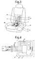
Figure 3 ] A schematic view of an embodiment of the present invention, showing an example of assembling a heating device in a seat. - [
Figure 4 ] An example of circuit layout of a heating device for a seat according to an embodiment of the present invention. - [
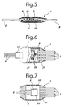
Figure 5 ] A section view of a heating device for a seat according to another embodiment of the present invention. - [
Figure 6 ] A partially cutaway plan view of another embodiment of the present invention, showing a temperature control circuit, serving as a part of the heating device for a seat, and being insulation-covered by heat-shrinkable tube, etc. - [
Figure 7 ] A section view of a heating device for a seat according to another embodiment of the present invention. - [
Figure 8 ] A plan view of a heating device for a seat according to a prior art. - [
Figure 9 ] A schematic view of a temperature control circuit serving as a part of a heating device for a seat according to a prior art. - [
Figure 10 ] A circuit layout of a heating device for a seat according to a prior art. -
- 1
- Temperature control circuit
- 2
- Base substance
- 3
- Heating wire
- 4
- Heating matter
- 5
- Temperature detection element
- 7
- Insulation-covering
- 8
- Lead wires
- 9
- Circuit board
- 10
- Reinforcing plate
- 11
- Protection tube
- E
- Power supply
- SW
- Switch
- VR
- Temperature setting variable resistance
- An embodiment of the present invention will be explained with reference to
Figs. 1 through 4 . As illustrated inFig. 1 , there is abase substance 2, on which a heating wire (cord-like heater) 3 is fixed, and aheating matter 4 comprises thebase substance 2 and theheating wire 3. There is also atemperature control circuit 1 placed at a predetermined position of thebase substance 2. There arelead wires 8, of which respective one ends are connected to thetemperature control circuit 1. The other ends of thelead wires 8 are connected, as illustrated inFig. 4 , to a power supply E, a temperature setting variable resistance VR, a switch SW, atemperature detection element 5, and theheating wire 3. Thetemperature detection element 5 is placed at a predetermined position on thebase substance 2, at which the temperature of theheating matter 4 may be detected as accurate as possible, and thelead wires 8 of thetemperature detection element 5 are connected to thetemperature control circuit 1 on thebase substance 2. - Accordingly, both the
temperature detection element 5 and thetemperature control circuit 1 have been placed at predetermined positions on thebase substance 2 in advance, they can be integrally attached to predetermined positions of aseating part 29 and a seat backpart 31 of a seat 27 (seeFig. 3 ), thus the workability for assembling them to theseat 27 may improve. Further, because the number of thelead wires 8, which are electrically connecting between theheating wire 3 and thetemperature control circuit 1, may be reduced, the production cost and the product weight may also be reduced. In addition, because the connecting length (distance) between thetemperature detection element 5 and thetemperature control circuit 1 may be shortened, the temperature control reliability may also improve. - As illustrated in
Fig. 2 , thetemperature control circuit 1 of the present embodiment has been insulation-covered together with a part of thelead wires 8 connected to thetemperature control circuit 1. The insulation-covering may be done by using a heat-shrinkable tube 7 composed of an organic material. There is a layer of thermoplastic adhesive 21 on the inner surface of the heat-shrinkable tube 7. After placing acircuit board 9 in the inside of this heat-shrinkable tube 7, the heat is applied to the heat-shrinkable tube 7, whereby the heat-shrinkable tube 7 is shrunken, and the surfaces of thecircuit board 9 is coated by thermoplastic adhesive 21 filled into these surfaces. As illustrated inFig. 2 , the meltedthermoplastic adhesive 21 is filled in an opening of the heat-shrinkable tube 7 without leaving any space.
It is also possible that, after placing thecircuit board 9 in the inside of the heat-shrinkable tube 7, any thermoplastic or thermosetting organic material may be filled from the opening of the heat-shrinkable tube 7. The length of insulation-covering of thelead wires 8 by the heat-shrinkable tube 7 has been set to a predetermined value at which the humidity-resistance is secured and the durability of thelead wires 8 against being bent may improve. - Accordingly, as long as the
temperature control circuit 1 is insulation-covered by the heat-shrinkable tube 7 together with a part of thelead wires 8, it is possible to prevent fire due to dew condensation of thecircuit board 1, and the insulation-covering may also ease the bending load applied to thelead wires 8, whereby the cut oflead wires 8 may be prevented. Further, any large-sized case body as described in paragraph 0004 is no longer required, and the size and thickness of thetemperature control circuit 1 may be reduced remarkably, thus the comfortable seating feeling may be given to the user without causing strange feeling. - The thickness of the insulation-covering on the
temperature control circuit 1, after being covered, is not more than 9 mm, because this thickness will not give any strange feeling to the user. Further, because thetemperature control circuit 1 is placed at a predetermined position of thebase substance 2 where no strange feeling is given to the user while being seated, the very comfortable seating feeling may be given to the user. - The insulation-covering of the
temperature control circuit 1 to be not more than 9 mm is not limited to the heat-shrinkable tube 7. For example, resin molding or resin potting may be used. Further, it is also possible to wrap thetemperature control circuit 1 by resin or rubber sheet on which adhesive has been coated. - As illustrated in
Fig. 6 , it is also possible to place aprotection tube 11 on thelead wires 8 in advance, serving as a protection covering, and thereafter, the heat-shrinkable tube 7 may be placed thereon and insulation-covering may be carried out. This will prevent thelead wires 8 from being cut due to bending of the end of insulation-covering, even when thelead wires 8 having smaller diameter are used. Theprotection tube 11 may be the same type as that of the heat-shrinkable tube for insulation-covering discussed above. - Examples of the present invention will be discussed further, with first reference to
Figs. 1 through 4 .
According to the present example, several electric and electronic parts are connected by thelead wires 8. As illustrated inFig. 4 , the positive electrode of the power supply E and thecircuit board 9 are connected via the switch SW, and the negative electrode of the power supply E and an end of theheating wire 3 are also connected. The positive electrode and the negative electrode of thelead wires 8 of thetemperature detection element 5 are both connected to thecircuit board 9 directly. Thecircuit board 9 and the temperature setting variable resistance VR are connected, and thecircuit board 9 is also grounded. - The
circuit board 9 is first placed in the inside of the heat-shrinkable tube 7, of which inner layer being provided with thethermoplastic adhesive 21, and of which outer layer is made of electron beam cross-linking olefin resin. Thereafter, the insulation-covering is done by applying heat thereto. At that time, the thickness of thetemperature control circuit 1 is set as not more than 9 mm. Thecircuit board 9 is insulation-covered by the heat-shrinkable tube 7 together with a part of thelead wires 8, and the covering length of suchlead wires 8 is preferably about 10 mm, which will satisfy good insulation performance and durability against being bent. - The
temperature detection element 5 is fixed on a predetermined position within a wiring space of theheating wire 3, where the temperature of the heating device for a seat may be detected accurately. If thetemperature detection element 5 is placed at an excessively close position to theheating wire 3, the heat of theheating wire 3 is detected before the temperature of the heating device for a seat reaches the set temperature, and the power supply to theheating wire 3 will be cut off at an inadequately earlier timing. - The
circuit board 9 which has been insulation-covered by the heat-shrinkable tube 7 is in small size (about 25 mm x 40 mm), in small thickness (not more than 9 mm), and is placed around theheating matter 4 at which any strange feeling is given to the user while being seated. - Further, as illustrated in
Fig. 5 , a reinforcingplate 10 made of resin, etc., may be placed on thecircuit board 9, and the insulation-covering is done by the heat-shrinkable tube 7. This structure will prevent thecircuit board 9 from being damaged due to impact and load of seating of the user. When the reinforcingplate 10 is used, the damage to thecircuit board 9 may be prevented more effectively, by placing the reinforcingplate 10 on the seating side of thetemperature control circuit 1. - It is also possible to incorporate the
temperature detection element 5 and thecircuit board 9 integrally in the heat-shrinkable tube 7 for the purpose of improving workability when thetemperature control circuit 1 is mounted on thebase substance 2. In such a case, for example, thetemperature detection element 5 may be placed at a position adjacent to anyelement 25 which generates heat (such as FET) among theelements 25 of thecircuit board 9, whereby the pseudo heat detection of thiselement 25 is done by thetemperature detection element 5, and the temperature control of theheating matter 4 may be carried out. - The
temperature detection element 5 may be placed on the other side of the reinforcingplate 10 on which theelements 25 of thecircuit board 9 have been placed. In such a case, as illustrated inFig. 7 , agroove 23 for incorporating thetemperature detection element 5 has been provided on the reinforcingplate 10, whereby thetemperature detection element 5 is incorporated in thisgroove 23. In addition, metal foil, such as made of aluminum, may be provided on the upper or lower surface of thetemperature detection element 5 for collecting the heat. - The
heating wire 3 has been arranged on thebase substance 2, and thetemperature control circuit 1 is placed on thebase substance 2 by double-face adhesive tape, etc. It is also possible to fix thetemperature control circuit 1 by a sheet at an appropriate size, made of the same material as that of thebase substance 2, on which the double-face adhesive tape has been pasted, for the purpose of improving fixing reliability. - As the
temperature detection element 5, for example, thermistor, platinum resistance element, or thermocouple may be used, and any suitable one may be selected by considering the temperature detection accuracy, production cost, etc. - Where conductivity providing agent is added to the heat-shrinkable tube 7 (i.e. the insulation-covering material), the
circuit board 9 may be shielded from noise generated inside the vehicle, and this is preferable from the viewpoint of preventing bad effect by noise. As the conductivity providing agent, any material known as prior art, for example, carbon black particle, graphite particle, ground carbon fiber, metal powder, metal-oxide powder, conductive polymer powder, etc., may be used. - As above discussed, according to the present invention, it is possible to provide the heating device for seat exhibiting excellent durability, reliability, safety and enhanced workability in fixing work to a seat, while reducing the cost and weight and ensuring comfortable feeling at seating without causing any strange feeling. The heating device for a seat may also be applied, for example, to seats of motorcycles or railway coaches, child safety seats, seats of boats or aircrafts, seats of Ferris wheel in amusement park, seats of various athletic stadiums, seats of theaters and cinemas, benches of stations, theme parks or ordinary parks, sofas and seats for houses and offices, seats of barbershop, medical seats used in various medical facilities, etc. Further, the present invention may be applied not only to seats, but also to various industrial fields widely, such as for beds, blankets and quilts, pillows, baby carriages, toilet seat covers, clothing, etc.
- The heating device for a seat according to the present invention may also be applied to a seat in which an air conditioner has been incorporated. Further, the present invention is not limited to be used inside the seat, and it is also possible to use on the outer surface of seat after assembly of the seat has been completed.
Claims (13)
- A heating device for a seat comprising:a heating matter including a base substance and a heating wire arranged on said base substance;a temperature detection element for detecting temperature of said heating matter; anda temperature control circuit for controlling temperature of said heating matter according to output signal from said temperature detection element, characterized in that,said temperature detection element and said temperature control circuit are arranged at predetermined positions on said base substance.
- The heating device for a seat as claimed in claim 1, further characterized in that,
said temperature control circuit is insulation-covered together with a part of lead wires connected to said temperature control circuit. - The heating device for a seat as claimed in claim 2, further characterized in that,
ends of said lead wires for connecting to said temperature control circuit have been protection-covered in advance, and then is insulation-covered together with said temperature control circuit. - The heating device for a seat as claimed in claim 2 or claim 3, further characterized in that,
said insulation-covering is done by heat-shrinkable tube. - The heating device for a seat as claimed in claim 4, further characterized in that,
said heat-shrinkable tube for said insulation-covering is provided with a thermoplastic adhesive layer in the inside of said heat-shrinkable tube. - The heating device for a seat as claimed in claim 1, further characterized in that,
said lead wires of said temperature detection element are connected to said temperature control circuit on said base substance. - The heating device for a seat as claimed in claim 1, further characterized in that,
said temperature control circuit has the thickness not more than 9 mm. - The heating device for a seat as claimed in claim 1, further characterized in that,
a surface among the upper and lower surfaces of said temperature control circuit, to which a load is applied when being mounted on a seat, is incorporating a reinforcing plate in the inside of said temperature control circuit. - The heating device for a seat as claimed in claim 1, further characterized in that,
said insulation-covering is done by incorporating said temperature detection element in said temperature control circuit. - The heating device for a seat as claimed in claim 9, further characterized in that,
said temperature detection element has been mounted at a position adjacent to electronic parts generating heat in the inside of said temperature control circuit. - The heating device for a seat as claimed in claim 9, further characterized in that,
a surface among the upper and lower surfaces of said temperature control circuit, to which a load is applied when being mounted on a seat, is incorporating a reinforcing plate in the inside of said temperature control circuit; and
said temperature detection element is mounted on the other side of said reinforcing plate on which electronic parts have been mounted. - The heating device for a seat as claimed in claim 9, further characterized in that,
at least one surface among the upper and lower surfaces of said temperature detection element is provided with a heat collecting metal foil. - The heating device for a seat as claimed in claim 9, further characterized in that,
said reinforcing plate has a groove for incorporating said temperature detection element in the inside of said groove.
Applications Claiming Priority (2)
| Application Number | Priority Date | Filing Date | Title |
|---|---|---|---|
| JP2005233820 | 2005-08-11 | ||
| PCT/JP2006/315872 WO2007018271A1 (en) | 2005-08-11 | 2006-08-10 | Heating device for seat |
Publications (3)
| Publication Number | Publication Date |
|---|---|
| EP1929901A1 true EP1929901A1 (en) | 2008-06-11 |
| EP1929901A4 EP1929901A4 (en) | 2011-07-06 |
| EP1929901B1 EP1929901B1 (en) | 2012-10-10 |
Family
ID=37727451
Family Applications (1)
| Application Number | Title | Priority Date | Filing Date |
|---|---|---|---|
| EP06782658A Active EP1929901B1 (en) | 2005-08-11 | 2006-08-10 | Heating device for seat |
Country Status (8)
| Country | Link |
|---|---|
| US (1) | US8492680B2 (en) |
| EP (1) | EP1929901B1 (en) |
| JP (1) | JP5116470B2 (en) |
| KR (1) | KR101327226B1 (en) |
| CN (1) | CN101242757B (en) |
| CA (1) | CA2618074C (en) |
| RU (1) | RU2403845C2 (en) |
| WO (1) | WO2007018271A1 (en) |
Cited By (3)
| Publication number | Priority date | Publication date | Assignee | Title |
|---|---|---|---|---|
| EP2437572A1 (en) * | 2009-05-26 | 2012-04-04 | Panasonic Corporation | Planar heating device and seat with same |
| WO2018080659A1 (en) * | 2016-10-31 | 2018-05-03 | Gentherm Gmbh | Carbon veil heater and method of making |
| WO2020192816A1 (en) * | 2019-03-28 | 2020-10-01 | Gentherm Gmbh | Electronic control unit for a heating device |
Families Citing this family (23)
| Publication number | Priority date | Publication date | Assignee | Title |
|---|---|---|---|---|
| DE102006031899B3 (en) * | 2006-04-20 | 2007-06-21 | W.E.T. Automotive Systems Ag | Interior component e.g. seat, surface air conditioning system for motor vehicle, has coating layer that is connected with air conditioning layer such that insertion case is formed, and detector device that is inserted into case |
| JP4861450B2 (en) * | 2009-05-12 | 2012-01-25 | 日本発條株式会社 | Vehicle seat device and heater unit used therefor |
| US8939501B2 (en) * | 2009-12-14 | 2015-01-27 | Panasonic Intellectual Property Management Co., Ltd. | Seat heater |
| US8567861B2 (en) * | 2009-12-25 | 2013-10-29 | Ts Tech Co., Ltd. | Seat with heater |
| JP5442427B2 (en) * | 2009-12-25 | 2014-03-12 | テイ・エス テック株式会社 | Seat with seat heater |
| CN102247943B (en) * | 2010-05-18 | 2013-07-03 | 鸿富锦精密工业(深圳)有限公司 | Adhesive dispensing device |
| JP5701571B2 (en) * | 2010-10-27 | 2015-04-15 | 株式会社クラベ | Seat heater |
| DE102011011344B4 (en) | 2011-02-16 | 2014-12-11 | Audi Ag | Circuit arrangement for an electric seat heating |
| CN103380026B (en) * | 2011-04-27 | 2016-03-23 | 松下知识产权经营株式会社 | Seat heater |
| DE102011121978B4 (en) * | 2011-11-17 | 2023-03-16 | Gentherm Gmbh | Heating or temperature control device |
| JP5805509B2 (en) * | 2011-11-30 | 2015-11-04 | トヨタ紡織株式会社 | Heater control device and vehicle seat heater |
| JP5960545B2 (en) * | 2012-08-13 | 2016-08-02 | テイ・エス テック株式会社 | Vehicle seat |
| JP6198934B2 (en) * | 2013-05-02 | 2017-09-20 | ジェンサーム ゲーエムベーハー | Liquid-resistant heating element |
| JP6177653B2 (en) * | 2013-10-10 | 2017-08-09 | テイ・エス テック株式会社 | Vehicle seat |
| KR101381073B1 (en) * | 2013-11-19 | 2014-04-04 | 송성진 | Functional chair for human body correction and thermal therapy |
| US9675180B2 (en) | 2015-03-13 | 2017-06-13 | Charles N Currie | Portable solar powered heated seat cushion |
| JP6043972B1 (en) * | 2015-04-08 | 2016-12-14 | パナソニックIpマネジメント株式会社 | Seat heater |
| DE102016003830A1 (en) | 2015-04-17 | 2016-10-20 | Gentherm Gmbh | Electric heating device, method for their production and vehicle seat with such a heater |
| US11096248B2 (en) * | 2015-05-29 | 2021-08-17 | Watlow Electric Manufacturing Company | Resistive heater with temperature sensing power pins and auxiliary sensing junction |
| CN104921535B (en) * | 2015-07-14 | 2016-08-24 | 成都市伺服液压设备有限公司 | A kind of multifunctional pillow |
| US10279714B2 (en) * | 2016-08-26 | 2019-05-07 | Ford Global Technologies, Llc | Seating assembly with climate control features |
| JP6713922B2 (en) * | 2016-12-21 | 2020-06-24 | 日本特殊陶業株式会社 | Wiring board for optical element mounting |
| WO2021205490A1 (en) * | 2020-04-05 | 2021-10-14 | 奥村真理子 | Hot furniture |
Citations (1)
| Publication number | Priority date | Publication date | Assignee | Title |
|---|---|---|---|---|
| US6252208B1 (en) * | 1997-11-25 | 2001-06-26 | Robert Bosch Gmbh | Method for controlling heating current and seat heating control circuit |
Family Cites Families (22)
| Publication number | Priority date | Publication date | Assignee | Title |
|---|---|---|---|---|
| JPS5921739A (en) | 1982-07-26 | 1984-02-03 | 津田駒工業株式会社 | Beam detaching and attaching apparatus of beam creel for warping machine |
| JPS5921739U (en) * | 1982-08-02 | 1984-02-09 | 松下電器産業株式会社 | temperature detector |
| US4542750A (en) | 1982-08-13 | 1985-09-24 | Primary Diagnostic Systems, Inc. | Non-invasive method for diagnosing incipient or developed cancer tissue |
| JPS5950362U (en) * | 1982-09-28 | 1984-04-03 | 松下電器産業株式会社 | Vehicle seat heater |
| JPS6271869U (en) * | 1985-10-24 | 1987-05-08 | ||
| US4813738A (en) * | 1988-01-04 | 1989-03-21 | Tachi-S Co., Ltd. | Automotive seat with heating device |
| US4865379A (en) * | 1988-02-04 | 1989-09-12 | Tachi-S Co., Ltd. | Automotive seat with heating device |
| SE465509B (en) * | 1988-03-04 | 1991-09-23 | Scandmec Mecania Ab | PROCEDURES FOR MANUFACTURING AN ELECTRIC HEATED VEHICLE AND ELECTRIC HEATED VEHICLE |
| DE3818974A1 (en) * | 1988-06-03 | 1990-02-08 | Ruthenberg Gmbh Waermetechnik | CONTROL AND MONITORING CIRCUIT FOR ELECTRIC SEAT HEATERS, ESPECIALLY OF MOTOR VEHICLES |
| US5176424A (en) * | 1988-06-10 | 1993-01-05 | Mazda Motor Corporation | Automobile seat assembly |
| JPH02108253U (en) * | 1988-10-07 | 1990-08-28 | ||
| CN2155741Y (en) * | 1993-03-16 | 1994-02-16 | 杨家建 | Adjustable electric heating chair |
| JPH08203706A (en) * | 1995-01-20 | 1996-08-09 | Matsushita Electric Ind Co Ltd | Manufacture of electronic component |
| US6073998A (en) * | 1996-10-15 | 2000-06-13 | Siarkowski; Bret | Seat warmer |
| DE19851979C2 (en) * | 1998-11-11 | 2000-08-31 | Daimler Chrysler Ag | Temperature sensor for an air-conditioned vehicle seat |
| US6189487B1 (en) * | 1999-04-09 | 2001-02-20 | Allied Precision Industries Inc. | Heated animal bed |
| JP2000342382A (en) * | 1999-06-07 | 2000-12-12 | Matsushita Electric Ind Co Ltd | Seat with heater |
| JP3289005B2 (en) * | 2000-06-14 | 2002-06-04 | 芳郎 野尻 | Seating load sensor and manufacturing method thereof |
| WO2002006083A1 (en) | 2000-07-17 | 2002-01-24 | Kongsberg Automotive Ab | Vehicle seat heating arrangement |
| JP2004217796A (en) | 2003-01-15 | 2004-08-05 | Kasei Optonix Co Ltd | Spherical rare earth oxide-based phosphor and method for producing the same |
| JP2004272755A (en) | 2003-03-11 | 2004-09-30 | Matsushita Electric Ind Co Ltd | Controller for seat heater |
| NO321923B1 (en) * | 2004-12-27 | 2006-07-24 | Nexans | Heating cable |
-
2006
- 2006-08-10 EP EP06782658A patent/EP1929901B1/en active Active
- 2006-08-10 KR KR1020087003798A patent/KR101327226B1/en active IP Right Grant
- 2006-08-10 US US11/990,201 patent/US8492680B2/en active Active
- 2006-08-10 WO PCT/JP2006/315872 patent/WO2007018271A1/en active Application Filing
- 2006-08-10 JP JP2007529624A patent/JP5116470B2/en active Active
- 2006-08-10 CA CA2618074A patent/CA2618074C/en active Active
- 2006-08-10 CN CN200680029575XA patent/CN101242757B/en active Active
- 2006-08-10 RU RU2008104502/12A patent/RU2403845C2/en active
Patent Citations (1)
| Publication number | Priority date | Publication date | Assignee | Title |
|---|---|---|---|---|
| US6252208B1 (en) * | 1997-11-25 | 2001-06-26 | Robert Bosch Gmbh | Method for controlling heating current and seat heating control circuit |
Non-Patent Citations (1)
| Title |
|---|
| See also references of WO2007018271A1 * |
Cited By (5)
| Publication number | Priority date | Publication date | Assignee | Title |
|---|---|---|---|---|
| EP2437572A1 (en) * | 2009-05-26 | 2012-04-04 | Panasonic Corporation | Planar heating device and seat with same |
| EP2437572A4 (en) * | 2009-05-26 | 2014-03-05 | Panasonic Corp | Planar heating device and seat with same |
| US8752891B2 (en) | 2009-05-26 | 2014-06-17 | Panasonic Corporation | Planar heating device and seat with same |
| WO2018080659A1 (en) * | 2016-10-31 | 2018-05-03 | Gentherm Gmbh | Carbon veil heater and method of making |
| WO2020192816A1 (en) * | 2019-03-28 | 2020-10-01 | Gentherm Gmbh | Electronic control unit for a heating device |
Also Published As
| Publication number | Publication date |
|---|---|
| KR20080038164A (en) | 2008-05-02 |
| EP1929901A4 (en) | 2011-07-06 |
| KR101327226B1 (en) | 2013-11-11 |
| CA2618074A1 (en) | 2007-02-15 |
| CA2618074C (en) | 2013-10-15 |
| RU2008104502A (en) | 2009-09-20 |
| US8492680B2 (en) | 2013-07-23 |
| RU2403845C2 (en) | 2010-11-20 |
| JPWO2007018271A1 (en) | 2009-02-19 |
| CN101242757B (en) | 2010-09-15 |
| US20090095725A1 (en) | 2009-04-16 |
| EP1929901B1 (en) | 2012-10-10 |
| WO2007018271A1 (en) | 2007-02-15 |
| JP5116470B2 (en) | 2013-01-09 |
| CN101242757A (en) | 2008-08-13 |
Similar Documents
| Publication | Publication Date | Title |
|---|---|---|
| EP1929901B1 (en) | Heating device for seat | |
| US9139119B2 (en) | Warmer equipment and warmer device for vehicle seat | |
| JP3996563B2 (en) | Flexible heater device | |
| KR101774798B1 (en) | Liquid resistant heating element | |
| US7667166B2 (en) | Heat-generating element of a heating device | |
| JP2004158438A5 (en) | ||
| US20110233183A1 (en) | Steering wheel heater assembly | |
| JP2005212556A (en) | Radiation heating device for vehicle | |
| WO2016017137A1 (en) | Heating device | |
| CN111301247A (en) | Sheet-type heating element and armrest of vehicle door including the same | |
| JP5072826B2 (en) | Heating device and warming device for vehicle seat | |
| CN102770720B (en) | Electric heater unit and corresponding assemble method | |
| JP2014046883A (en) | Vehicular heating device | |
| CN111094034B (en) | Automobile door decoration | |
| WO2016017140A1 (en) | Vehicle heating device | |
| CN219564863U (en) | Heating module for automobile seat and automobile seat | |
| JP4577219B2 (en) | Mounting structure and mounting method for vehicle heating device | |
| WO2018061702A1 (en) | Radiation heater device | |
| JPH10154574A (en) | Planar heating element | |
| JPH1187020A (en) | Heating sheet and manufacture thereof |
Legal Events
| Date | Code | Title | Description |
|---|---|---|---|
| PUAI | Public reference made under article 153(3) epc to a published international application that has entered the european phase |
Free format text: ORIGINAL CODE: 0009012 |
|
| 17P | Request for examination filed |
Effective date: 20080226 |
|
| AK | Designated contracting states |
Kind code of ref document: A1 Designated state(s): AT BE BG CH CY CZ DE DK EE ES FI FR GB GR HU IE IS IT LI LT LU LV MC NL PL PT RO SE SI SK TR |
|
| A4 | Supplementary search report drawn up and despatched |
Effective date: 20110609 |
|
| GRAP | Despatch of communication of intention to grant a patent |
Free format text: ORIGINAL CODE: EPIDOSNIGR1 |
|
| DAX | Request for extension of the european patent (deleted) | ||
| GRAS | Grant fee paid |
Free format text: ORIGINAL CODE: EPIDOSNIGR3 |
|
| GRAA | (expected) grant |
Free format text: ORIGINAL CODE: 0009210 |
|
| AK | Designated contracting states |
Kind code of ref document: B1 Designated state(s): AT BE BG CH CY CZ DE DK EE ES FI FR GB GR HU IE IS IT LI LT LU LV MC NL PL PT RO SE SI SK TR |
|
| REG | Reference to a national code |
Ref country code: GB Ref legal event code: FG4D |
|
| REG | Reference to a national code |
Ref country code: CH Ref legal event code: EP Ref country code: AT Ref legal event code: REF Ref document number: 578552 Country of ref document: AT Kind code of ref document: T Effective date: 20121015 |
|
| REG | Reference to a national code |
Ref country code: IE Ref legal event code: FG4D |
|
| REG | Reference to a national code |
Ref country code: DE Ref legal event code: R096 Ref document number: 602006032416 Country of ref document: DE Effective date: 20121206 |
|
| PG25 | Lapsed in a contracting state [announced via postgrant information from national office to epo] |
Ref country code: SI Free format text: LAPSE BECAUSE OF FAILURE TO SUBMIT A TRANSLATION OF THE DESCRIPTION OR TO PAY THE FEE WITHIN THE PRESCRIBED TIME-LIMIT Effective date: 20121010 |
|
| REG | Reference to a national code |
Ref country code: NL Ref legal event code: VDEP Effective date: 20121010 |
|
| REG | Reference to a national code |
Ref country code: AT Ref legal event code: MK05 Ref document number: 578552 Country of ref document: AT Kind code of ref document: T Effective date: 20121010 |
|
| REG | Reference to a national code |
Ref country code: LT Ref legal event code: MG4D |
|
| PG25 | Lapsed in a contracting state [announced via postgrant information from national office to epo] |
Ref country code: ES Free format text: LAPSE BECAUSE OF FAILURE TO SUBMIT A TRANSLATION OF THE DESCRIPTION OR TO PAY THE FEE WITHIN THE PRESCRIBED TIME-LIMIT Effective date: 20130121 Ref country code: NL Free format text: LAPSE BECAUSE OF FAILURE TO SUBMIT A TRANSLATION OF THE DESCRIPTION OR TO PAY THE FEE WITHIN THE PRESCRIBED TIME-LIMIT Effective date: 20121010 Ref country code: SE Free format text: LAPSE BECAUSE OF FAILURE TO SUBMIT A TRANSLATION OF THE DESCRIPTION OR TO PAY THE FEE WITHIN THE PRESCRIBED TIME-LIMIT Effective date: 20121010 Ref country code: IS Free format text: LAPSE BECAUSE OF FAILURE TO SUBMIT A TRANSLATION OF THE DESCRIPTION OR TO PAY THE FEE WITHIN THE PRESCRIBED TIME-LIMIT Effective date: 20130210 Ref country code: FI Free format text: LAPSE BECAUSE OF FAILURE TO SUBMIT A TRANSLATION OF THE DESCRIPTION OR TO PAY THE FEE WITHIN THE PRESCRIBED TIME-LIMIT Effective date: 20121010 Ref country code: LT Free format text: LAPSE BECAUSE OF FAILURE TO SUBMIT A TRANSLATION OF THE DESCRIPTION OR TO PAY THE FEE WITHIN THE PRESCRIBED TIME-LIMIT Effective date: 20121010 |
|
| PG25 | Lapsed in a contracting state [announced via postgrant information from national office to epo] |
Ref country code: CY Free format text: LAPSE BECAUSE OF FAILURE TO SUBMIT A TRANSLATION OF THE DESCRIPTION OR TO PAY THE FEE WITHIN THE PRESCRIBED TIME-LIMIT Effective date: 20121010 Ref country code: LV Free format text: LAPSE BECAUSE OF FAILURE TO SUBMIT A TRANSLATION OF THE DESCRIPTION OR TO PAY THE FEE WITHIN THE PRESCRIBED TIME-LIMIT Effective date: 20121010 Ref country code: BE Free format text: LAPSE BECAUSE OF FAILURE TO SUBMIT A TRANSLATION OF THE DESCRIPTION OR TO PAY THE FEE WITHIN THE PRESCRIBED TIME-LIMIT Effective date: 20121010 Ref country code: PT Free format text: LAPSE BECAUSE OF FAILURE TO SUBMIT A TRANSLATION OF THE DESCRIPTION OR TO PAY THE FEE WITHIN THE PRESCRIBED TIME-LIMIT Effective date: 20130211 Ref country code: PL Free format text: LAPSE BECAUSE OF FAILURE TO SUBMIT A TRANSLATION OF THE DESCRIPTION OR TO PAY THE FEE WITHIN THE PRESCRIBED TIME-LIMIT Effective date: 20121010 Ref country code: GR Free format text: LAPSE BECAUSE OF FAILURE TO SUBMIT A TRANSLATION OF THE DESCRIPTION OR TO PAY THE FEE WITHIN THE PRESCRIBED TIME-LIMIT Effective date: 20130111 |
|
| PG25 | Lapsed in a contracting state [announced via postgrant information from national office to epo] |
Ref country code: AT Free format text: LAPSE BECAUSE OF FAILURE TO SUBMIT A TRANSLATION OF THE DESCRIPTION OR TO PAY THE FEE WITHIN THE PRESCRIBED TIME-LIMIT Effective date: 20121010 |
|
| PG25 | Lapsed in a contracting state [announced via postgrant information from national office to epo] |
Ref country code: BG Free format text: LAPSE BECAUSE OF FAILURE TO SUBMIT A TRANSLATION OF THE DESCRIPTION OR TO PAY THE FEE WITHIN THE PRESCRIBED TIME-LIMIT Effective date: 20130110 Ref country code: CZ Free format text: LAPSE BECAUSE OF FAILURE TO SUBMIT A TRANSLATION OF THE DESCRIPTION OR TO PAY THE FEE WITHIN THE PRESCRIBED TIME-LIMIT Effective date: 20121010 Ref country code: SK Free format text: LAPSE BECAUSE OF FAILURE TO SUBMIT A TRANSLATION OF THE DESCRIPTION OR TO PAY THE FEE WITHIN THE PRESCRIBED TIME-LIMIT Effective date: 20121010 Ref country code: DK Free format text: LAPSE BECAUSE OF FAILURE TO SUBMIT A TRANSLATION OF THE DESCRIPTION OR TO PAY THE FEE WITHIN THE PRESCRIBED TIME-LIMIT Effective date: 20121010 Ref country code: EE Free format text: LAPSE BECAUSE OF FAILURE TO SUBMIT A TRANSLATION OF THE DESCRIPTION OR TO PAY THE FEE WITHIN THE PRESCRIBED TIME-LIMIT Effective date: 20121010 |
|
| PLBE | No opposition filed within time limit |
Free format text: ORIGINAL CODE: 0009261 |
|
| STAA | Information on the status of an ep patent application or granted ep patent |
Free format text: STATUS: NO OPPOSITION FILED WITHIN TIME LIMIT |
|
| PG25 | Lapsed in a contracting state [announced via postgrant information from national office to epo] |
Ref country code: RO Free format text: LAPSE BECAUSE OF FAILURE TO SUBMIT A TRANSLATION OF THE DESCRIPTION OR TO PAY THE FEE WITHIN THE PRESCRIBED TIME-LIMIT Effective date: 20121010 Ref country code: IT Free format text: LAPSE BECAUSE OF FAILURE TO SUBMIT A TRANSLATION OF THE DESCRIPTION OR TO PAY THE FEE WITHIN THE PRESCRIBED TIME-LIMIT Effective date: 20121010 |
|
| 26N | No opposition filed |
Effective date: 20130711 |
|
| REG | Reference to a national code |
Ref country code: DE Ref legal event code: R097 Ref document number: 602006032416 Country of ref document: DE Effective date: 20130711 |
|
| REG | Reference to a national code |
Ref country code: CH Ref legal event code: PL |
|
| GBPC | Gb: european patent ceased through non-payment of renewal fee |
Effective date: 20130810 |
|
| PG25 | Lapsed in a contracting state [announced via postgrant information from national office to epo] |
Ref country code: CH Free format text: LAPSE BECAUSE OF NON-PAYMENT OF DUE FEES Effective date: 20130831 Ref country code: LI Free format text: LAPSE BECAUSE OF NON-PAYMENT OF DUE FEES Effective date: 20130831 Ref country code: MC Free format text: LAPSE BECAUSE OF FAILURE TO SUBMIT A TRANSLATION OF THE DESCRIPTION OR TO PAY THE FEE WITHIN THE PRESCRIBED TIME-LIMIT Effective date: 20121010 |
|
| REG | Reference to a national code |
Ref country code: IE Ref legal event code: MM4A |
|
| REG | Reference to a national code |
Ref country code: FR Ref legal event code: ST Effective date: 20140430 |
|
| PG25 | Lapsed in a contracting state [announced via postgrant information from national office to epo] |
Ref country code: GB Free format text: LAPSE BECAUSE OF NON-PAYMENT OF DUE FEES Effective date: 20130810 Ref country code: IE Free format text: LAPSE BECAUSE OF NON-PAYMENT OF DUE FEES Effective date: 20130810 |
|
| PG25 | Lapsed in a contracting state [announced via postgrant information from national office to epo] |
Ref country code: FR Free format text: LAPSE BECAUSE OF NON-PAYMENT OF DUE FEES Effective date: 20130902 |
|
| PG25 | Lapsed in a contracting state [announced via postgrant information from national office to epo] |
Ref country code: TR Free format text: LAPSE BECAUSE OF FAILURE TO SUBMIT A TRANSLATION OF THE DESCRIPTION OR TO PAY THE FEE WITHIN THE PRESCRIBED TIME-LIMIT Effective date: 20121010 |
|
| PG25 | Lapsed in a contracting state [announced via postgrant information from national office to epo] |
Ref country code: LU Free format text: LAPSE BECAUSE OF NON-PAYMENT OF DUE FEES Effective date: 20130810 Ref country code: HU Free format text: LAPSE BECAUSE OF FAILURE TO SUBMIT A TRANSLATION OF THE DESCRIPTION OR TO PAY THE FEE WITHIN THE PRESCRIBED TIME-LIMIT; INVALID AB INITIO Effective date: 20060810 |
|
| PGFP | Annual fee paid to national office [announced via postgrant information from national office to epo] |
Ref country code: DE Payment date: 20230830 Year of fee payment: 18 |