EP1941456B1 - Method of bioimage data processing for revealing more meaningful anatomic features of diseased tissues - Google Patents
Method of bioimage data processing for revealing more meaningful anatomic features of diseased tissues Download PDFInfo
- Publication number
- EP1941456B1 EP1941456B1 EP06791726A EP06791726A EP1941456B1 EP 1941456 B1 EP1941456 B1 EP 1941456B1 EP 06791726 A EP06791726 A EP 06791726A EP 06791726 A EP06791726 A EP 06791726A EP 1941456 B1 EP1941456 B1 EP 1941456B1
- Authority
- EP
- European Patent Office
- Prior art keywords
- recited
- points
- map
- elevational
- reference surface
- Prior art date
- Legal status (The legal status is an assumption and is not a legal conclusion. Google has not performed a legal analysis and makes no representation as to the accuracy of the status listed.)
- Active
Links
- 238000000034 method Methods 0.000 title claims abstract description 46
- 238000012545 processing Methods 0.000 title description 5
- 238000009877 rendering Methods 0.000 claims abstract description 20
- 210000003583 retinal pigment epithelium Anatomy 0.000 claims description 46
- 210000001519 tissue Anatomy 0.000 claims description 45
- 238000012014 optical coherence tomography Methods 0.000 claims description 26
- 210000001525 retina Anatomy 0.000 claims description 26
- 239000000523 sample Substances 0.000 claims description 14
- 201000010099 disease Diseases 0.000 claims description 8
- 208000037265 diseases, disorders, signs and symptoms Diseases 0.000 claims description 8
- 239000012528 membrane Substances 0.000 claims description 6
- 239000012472 biological sample Substances 0.000 claims description 3
- 210000004087 cornea Anatomy 0.000 claims description 3
- 238000002604 ultrasonography Methods 0.000 claims description 3
- 238000010226 confocal imaging Methods 0.000 claims description 2
- 210000004204 blood vessel Anatomy 0.000 claims 1
- 230000001419 dependent effect Effects 0.000 abstract description 2
- 230000002207 retinal effect Effects 0.000 description 15
- 239000000835 fiber Substances 0.000 description 5
- 238000013507 mapping Methods 0.000 description 5
- 230000011218 segmentation Effects 0.000 description 5
- 230000003287 optical effect Effects 0.000 description 4
- 230000003595 spectral effect Effects 0.000 description 4
- 230000002159 abnormal effect Effects 0.000 description 3
- 238000004624 confocal microscopy Methods 0.000 description 3
- 230000000694 effects Effects 0.000 description 3
- 208000014674 injury Diseases 0.000 description 3
- 239000013307 optical fiber Substances 0.000 description 3
- 206010016035 Face presentation Diseases 0.000 description 2
- 208000027418 Wounds and injury Diseases 0.000 description 2
- 230000004075 alteration Effects 0.000 description 2
- 238000004458 analytical method Methods 0.000 description 2
- 230000006378 damage Effects 0.000 description 2
- 238000010586 diagram Methods 0.000 description 2
- 238000001914 filtration Methods 0.000 description 2
- 238000009499 grossing Methods 0.000 description 2
- 238000003384 imaging method Methods 0.000 description 2
- 230000003902 lesion Effects 0.000 description 2
- 238000005259 measurement Methods 0.000 description 2
- 230000007170 pathology Effects 0.000 description 2
- 238000000711 polarimetry Methods 0.000 description 2
- 230000010287 polarization Effects 0.000 description 2
- 210000001747 pupil Anatomy 0.000 description 2
- 230000004256 retinal image Effects 0.000 description 2
- 241001270131 Agaricus moelleri Species 0.000 description 1
- 201000001320 Atherosclerosis Diseases 0.000 description 1
- 208000024172 Cardiovascular disease Diseases 0.000 description 1
- 208000001344 Macular Edema Diseases 0.000 description 1
- 206010025415 Macular oedema Diseases 0.000 description 1
- 206010025421 Macule Diseases 0.000 description 1
- 206010028980 Neoplasm Diseases 0.000 description 1
- 201000010183 Papilledema Diseases 0.000 description 1
- 206010073286 Pathologic myopia Diseases 0.000 description 1
- 206010038886 Retinal oedema Diseases 0.000 description 1
- 206010041951 Staphyloma Diseases 0.000 description 1
- 210000003484 anatomy Anatomy 0.000 description 1
- 238000013459 approach Methods 0.000 description 1
- 230000015572 biosynthetic process Effects 0.000 description 1
- 201000004709 chorioretinitis Diseases 0.000 description 1
- 208000031513 cyst Diseases 0.000 description 1
- 230000007850 degeneration Effects 0.000 description 1
- 230000002542 deteriorative effect Effects 0.000 description 1
- 238000003745 diagnosis Methods 0.000 description 1
- 238000002059 diagnostic imaging Methods 0.000 description 1
- 238000005516 engineering process Methods 0.000 description 1
- 210000002615 epidermis Anatomy 0.000 description 1
- 238000007519 figuring Methods 0.000 description 1
- 238000003709 image segmentation Methods 0.000 description 1
- 201000010230 macular retinal edema Diseases 0.000 description 1
- 208000001491 myopia Diseases 0.000 description 1
- 230000004379 myopia Effects 0.000 description 1
- 238000012634 optical imaging Methods 0.000 description 1
- 238000000399 optical microscopy Methods 0.000 description 1
- 230000001575 pathological effect Effects 0.000 description 1
- 238000003672 processing method Methods 0.000 description 1
- 201000011195 retinal edema Diseases 0.000 description 1
- 230000035945 sensitivity Effects 0.000 description 1
- 210000003491 skin Anatomy 0.000 description 1
- 238000012876 topography Methods 0.000 description 1
- 230000008733 trauma Effects 0.000 description 1
- 238000012285 ultrasound imaging Methods 0.000 description 1
- 210000004127 vitreous body Anatomy 0.000 description 1
Images


Classifications
-
- A—HUMAN NECESSITIES
- A61—MEDICAL OR VETERINARY SCIENCE; HYGIENE
- A61B—DIAGNOSIS; SURGERY; IDENTIFICATION
- A61B5/00—Measuring for diagnostic purposes; Identification of persons
- A61B5/0059—Measuring for diagnostic purposes; Identification of persons using light, e.g. diagnosis by transillumination, diascopy, fluorescence
- A61B5/0062—Arrangements for scanning
- A61B5/0066—Optical coherence imaging
-
- G—PHYSICS
- G06—COMPUTING; CALCULATING OR COUNTING
- G06T—IMAGE DATA PROCESSING OR GENERATION, IN GENERAL
- G06T19/00—Manipulating 3D models or images for computer graphics
-
- G—PHYSICS
- G06—COMPUTING; CALCULATING OR COUNTING
- G06T—IMAGE DATA PROCESSING OR GENERATION, IN GENERAL
- G06T7/00—Image analysis
- G06T7/0002—Inspection of images, e.g. flaw detection
- G06T7/0012—Biomedical image inspection
- G06T7/0014—Biomedical image inspection using an image reference approach
-
- G—PHYSICS
- G06—COMPUTING; CALCULATING OR COUNTING
- G06T—IMAGE DATA PROCESSING OR GENERATION, IN GENERAL
- G06T2200/00—Indexing scheme for image data processing or generation, in general
- G06T2200/24—Indexing scheme for image data processing or generation, in general involving graphical user interfaces [GUIs]
-
- G—PHYSICS
- G06—COMPUTING; CALCULATING OR COUNTING
- G06T—IMAGE DATA PROCESSING OR GENERATION, IN GENERAL
- G06T2207/00—Indexing scheme for image analysis or image enhancement
- G06T2207/10—Image acquisition modality
- G06T2207/10072—Tomographic images
- G06T2207/10101—Optical tomography; Optical coherence tomography [OCT]
-
- G—PHYSICS
- G06—COMPUTING; CALCULATING OR COUNTING
- G06T—IMAGE DATA PROCESSING OR GENERATION, IN GENERAL
- G06T2207/00—Indexing scheme for image analysis or image enhancement
- G06T2207/30—Subject of image; Context of image processing
- G06T2207/30004—Biomedical image processing
- G06T2207/30041—Eye; Retina; Ophthalmic
-
- G—PHYSICS
- G06—COMPUTING; CALCULATING OR COUNTING
- G06T—IMAGE DATA PROCESSING OR GENERATION, IN GENERAL
- G06T2210/00—Indexing scheme for image generation or computer graphics
- G06T2210/41—Medical
Definitions
- One or more embodiments of the present invention relate generally to methods for optical imaging of biological samples and for processing such images.
- the invention is a method for processing a three-dimensional image data set to generate elevation maps of tissue layers relative to a fitted smooth surface, which can provide more diagnostic information than a pure tissue layer thickness map.
- Maps of elevation may be embodied as three-dimensional surface renderings of elevation, topographical maps, or as color or grayscale maps.
- Measurement of biological tissue surface contour or layer thickness can provide useful diagnostic information in various applications.
- arterial plaque thickness is related to the progress of atherosclerosis
- carotid vessel wall thickness is also an indicator of cardiovascular disease risk
- epidermal layer thickness is an indicator of burn severity.
- retinal thickness may be abnormally large in cases of retinal edema or traction by membranes in the vitreous humor.
- the retina may appear thin in cases of atrophic degeneration, chorioretinitis, or trauma to the retina.
- changes in retinal thickness may be localized or extend over large areas.
- the overall contour of the retina may become abnormal. For example, pronounced myopia, particularly due to posterior staphylomas, may create a highly concave retina. Detachment of the retinal pigment epithelium (RPE), subretinal cysts, or subretinal tumors may produce a relative convexity of the retina. Therefore, mapping the retina contour or retinal thickness makes it possible to determine the extent and severity of such conditions and to monitor progress of treatment.
- RPE retinal pigment epithelium
- the three-dimensional data set has also been analyzed to identify layered structures in the tissue using a variety of approaches to image segmentation.
- approaches to image segmentation see for example, D. G. Bartsch, et al., (2004) "Optical coherence tomography: interpretation artifacts and new algorithm", Proc. SPIE Medical Imaging 2004: Image Processing, 5370: 2140-2151 ; H. Ishikawa, et al., (2005) "Macular Segmentation with Optical Coherence Tomography”. Invest Ophthalmol Vis Sci.; 46: 2012-201 ).
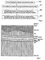
- retina thickness is defined as the vertical distance between the RPE (retinal pigment epithelium) 102 and the ILM (inner limiting membrane) 104 as shown in Fig. 1 .
- a sharp bump 106 of the retina will often be associated with a rise in the RPE 102 as well as the formation of a lesion 108 below the RPE 102, such that the RPE also has a broad rise.
- a retina thickness map such as the color coded one shown in Fig. 2 , which corresponds to Fig. 1 , cannot reveal the substantially raised bump.
- the color coded thickness map shows that the thickness will only slightly increase near the bump but then return to normal over it.
- a topographic map or contour of the RPE or ILM may reveal the sharp bump better for this illustrated case than the retina thickness map, it would include both the sharp bump and the broader warping of the RPE boundary, making it difficult to separate the effect of the disease from the overall shape of the RPE boundary.
- the present invention is a novel and non-obvious method as set out in the appended claims, wherein a fitted reference surface is used to create an elevation map or image of a tissue layer/boundary with respect to the fitted reference surface.
- a fitted reference surface is used to create an elevation map or image of a tissue layer/boundary with respect to the fitted reference surface.
- Use of such a fitted surface can minimize the perturbations of the surface associated with disease so as to approximate the tissue surface that would exist if the tissue were normal.
- the invention also combines the elevation data with other maps or images in order to provide more meaningful information for diagnostics.
- one embodiment of the present invention is a method for generating elevation maps or images of a tissue layer/boundary with respect to the location of a fitted reference surface, comprising the steps of finding and segmenting a desired tissue layer/boundary; fitting a smooth reference surface to the segmented tissue layer/boundary; calculating elevations of the same or other tissue layer/boundary relative to the fitted reference surface; and generating maps of elevation relative to the fitted surface.
- One aspect of the present invention is to display the elevation in various ways including three-dimensional surface renderings, topographical contour maps, contour maps, en-face color maps, and en-face grayscale maps.
- Another aspect of the present invention is to combine and hence simultaneously display on the same map and/or image two sets of data with one set from the elevation relative to a fitted reference surface and the other set from a tissue layer/boundary dependent information, including, for example, actual thickness of a tissue layer, and image signal strength such as reflectance from an OCT system, birefringence from a polarization sensitive OCT system or a scanning laser polarimetry system, and intensity from a confocal imaging system.
- Another aspect of the present invention is to perform the fitting to obtain the reference surface in a number of ways, including using a second-order polynomial fit, or using Zernike or Chebyshev or other polynomials, or Bessel functions, or a portion of a sphere or spheroid. Additionally, the fitting can also be performed by excluding certain portions of the tissue layer/boundary, i.e. the regions of diseased tissue, from the determination of the fitted reference surface, or fitting on more than one region of the tissue layer/boundary or smoothing/filtering a tissue layer/boundary.
- Still another aspect of the invention is to locate the general tissue layer/boundary contour for subsequent scans, which need to follow the tissue contour closely.
- Fig. 1 shows OCT images of a retina, illustrating RPE (retinal pigment epithelium), the ILM (inner limiting membrane), a sharp bump and a lesion below the sharp bump.
- RPE retina pigment epithelium
- ILM inner limiting membrane
- Fig. 2 is a color coded retina thickness map corresponding to Fig. 1
- Fig. 3 shows a flow diagram of the steps of the invented image processing method.
- Fig. 4 shows a retina image with the hue mapped as the square of the distance from the fitted RPE reference surface
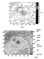
- Fig. 5 shows a contour plot using the color coding that represents the distance from the ILM to a paraboloid fitted RPE reference surface
- Fig. 6 shows a pseudocolor image representing the distance from the ILM to a paraboloid fitted RPE reference surface
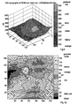
- Fig. 7 shows a three-dimensional rendering of the ILM surface elevation relative to the paraboloid fitted RPE reference surface, with the color indicating in duplicate the same elevation information.
- Fig. 8 shows a three-dimensional rendering of the actual retina thickness superimposed with a pseudocolor image indicating ILM elevation with respect to the paraboloid fitted RPE reference surface
- Fig. 9 shows a three-dimensional rendering of the ILM surface elevation relative to the paraboloid fitted RPE reference surface superimposed with a pseudocolor image indicating actual retinal thickness
- Fig. 10 shows a pseudocolor image representing the distance from the RPE to a paraboloid fitted RPE reference surface.
- Fig. 11 is a schematic diagram of a basic OCT system capable of generating 3D image data that can be used in the method of the subject invention.
- Fig. 3 shows one preferred embodiment the presently invented method. This method is intended to be used on image data obtained from a sample.
- the illustrations in this application are based on image data derived from an optical coherence tomography system (OCT) which includes both time domain and spectral domain OCT systems.
- OCT optical coherence tomography
- Such an instrument generates 3D intensity data corresponding to an axial reflection distribution arising from reflecting features in the eye.
- OCT optical coherence tomography system
- Such an instrument generates 3D intensity data corresponding to an axial reflection distribution arising from reflecting features in the eye.
- this information is currently used by doctors to view and diagnosis various pathologies in the eye.
- a basic OCT system will be discussed below.
- image processing concepts described herein may be used with 3D image data derived from other modalities.
- image data may be created using various forms of confocal microscopy and even ultrasound imaging modalities.
- boundary surface can be a limiting surface in the sample, a surface of a layer or other interface.
- the boundary should have a sufficient linear or 2D extent that it can be reasonably fitted to a geometric line or surface.
- Identification of the image data corresponding to a boundary surface is performed using a segmenting function.
- Methods for finding and segmenting a desired tissue layer or boundary surface are well-known in the art.(see for example, H. Ishikawa, et al., (2005) "Macular Segmentation with Optical Coherence Tomography”. Invest Ophthalmol Vis Sci.; 46: 2012-201 ).
- the boundary is fitted to a substantially smooth reference surface (step 304).
- a substantially smooth reference surface There are a number of well-known methods for fitting a measured surface data points to a geometric surface.
- One example is a second-order polynomial fit.
- Other functions including Zernike or Chebyshev polynomials, Bessel functions, or a portion of a sphere or spheroid, can also be used for surface fitting.
- a smooth reference surface can be formed by fitting the shape of a tissue layer/boundary with a function of two variables. This requires a reasonably accurate segmentation of the chosen tissue layer/boundary and can be accomplished using, for example, a low-order polynomial fit in x and y.
- the fitting may encompass the entire tissue layer/boundary or may be performed on various regions of the surface, e.g., fitting the foveal pit separately from the macula, or excluding pathological regions from the fitting.
- the reference surfaces can be used to define layers in the data that have the retinal tilt and curvature removed. In one aspect of the invention, these data points can be used to form en-face images representing retinal structures in those layers. This presents an advantage over the flat C-scan presentation of the data when imaging the curved layers in the anatomy of the eye, since a C-scan will only show tangential slices of the retinal layers.
- a fitted surface can minimize the perturbations of the surface associated with disease so as to approximate the tissue surface that would exist if the tissue were normal.
- the fitting algorithm will function to reject points that are associated with the selected boundary surface but exist as a result of the disease.
- the distances or elevations between points on the reference surface and some other feature of interest are calculated.
- the feature of interest may be the actual boundary initially selected so that elevations will correspond to the deviations between the selected surface and the associated reference surface.
- the feature of interest can also be another interface or boundary within the sample.
- 2D data sets are generated based on the calculated distances between the reference surface and other feature of interest.
- the 2D data sets can be used to create elevation maps.
- the elevation maps may be created based on pseudocolor or gray scales with elevation encoded as color as shown in Fig. 6 or intensity (not shown); or as topographical contour maps with elevation encoded as contour height as shown in Fig. 5 or as three dimensionally rendered topographical maps.
- These types of maps may also be combined to simultaneously display on the same map two sets of data, one for elevation relative to a fitted reference surface and the other for either another elevation relative to another reference surface, or an actual tissue layer thickness, or the originally collected image signal strength such as OCT or confocal optical signal strength for a tissue layer or other processed/unprocessed tissue layer/boundary data such as birefringence measured from a polarization sensitive OCT system or a scanning laser polarimetry system.
- the distance from ILM relative to the RPE i.e. the actual retina thickness
- a pseudocolor map may be applied to a three-dimensional surface rendering in order to simultaneously display multiple information on elevation, thickness, reflectance or others.
- the present invention has a number of other advantages over prior art methods as it can provide additional useful information for diagnosing diseased tissues.
- the fitted reference surface can be used as a basis for elevation maps of retinal layers, to diagnose abnormal curvature of the retina, or as a guide for subsequent contour-following scans of that eye. Using such a fitted reference surface as a basis for "thickness" measurements could give more robust results because the exact topography of a deteriorating RPE may be more difficult to determine than the general shape of that layer.
- map(s) of elevation can be displayed in the form of topographical contour map(s) applied to surface renderings of elevation.
- Fig. 5 shows a color contour coding that represents the distance from the ILM to a paraboloid reference surface fitted to the RPE. The corrected effective retinal "thickness" relative to the fitted surface is shown in microns on the color bar to the right of the map.
- presentation of topographic information relative to a fitted reference surface or surfaces can generate images with added information, for example:
- Axial resolution may be wasted if the z-range of the scan does not follow the contour of the retinal tissue.
- a few initial scans could be used to determine the reference surface, then a retina-following scan could be performed by changing the OCT reference arm length to follow the predetermined reference surface as the transverse scans are performed.
- Fig. 4 shows a B-scan retina image with the hue mapped as the square of the distance from the fitted RPE reference surface. The vertical distance in the image relative to the location of the fitted RPE reference surface is encoded as a color which is used to highlight the image.
- the present invention does not need to follow the exact sequence as shown in Fig. 3 , as other additional steps can be inserted to perform substantially equivalent operations.
- the fitting operation may be approximated by smoothing or otherwise filtering the retinal layer.
- the reference surface might not be the direct result of fitting, but some filtered version thereof.
- a variation of this idea could use two such reference surfaces, rather than the elevation from an unfitted surface to a reference surface.
- the presently invented method could be applied to the analysis of the retina or curvature of the eye in existing and future OCT systems. It can also be used for analysis of other biological tissues such as the skin. Also, it may find use in ultrasound and confocal microscopy systems as well.
- Fig. 11 shows a basic spectrometer based spectral domain OCT system 1100.
- the light wave from the broadband emitter 1110 is preferably coupled through a short length of an optical fiber 1112 to an input port (port I) of a fiber optic coupler 1114, which splits the incoming light beam into the two arms of a Michelson interferometer.
- the two arms each have a section of optical fiber (1116 and 1118) that guides the split light beam from the two output ports (port II and port III) of the fiber coupler 1114 to a sample 1124 and a reference reflector 1126 respectively.
- Illustrated in Figure 11 as an embodiment are two focusing lenses 1120 and 1122.
- the returned light waves from the sample 1124 and the reference reflector 1126 are directed back through the same optical path of the sample and reference arms and are combined in fiber coupler 1114.
- a portion of the combined light beam is directed through a section of optical fiber 1130 from port IV of the fiber coupler 1114 to a spectrometer 1150.
- the light beam is dispersed by a grating 1152 and focused onto a detector array 1154.
- the principle of operation of a tunable laser based swept source OCT is very similar to that of a spectrometer based spectral domain OCT system (see for example, Choma, M. A. et al. (2003).
Abstract
Description
- One or more embodiments of the present invention relate generally to methods for optical imaging of biological samples and for processing such images. In particular, the invention is a method for processing a three-dimensional image data set to generate elevation maps of tissue layers relative to a fitted smooth surface, which can provide more diagnostic information than a pure tissue layer thickness map. Maps of elevation may be embodied as three-dimensional surface renderings of elevation, topographical maps, or as color or grayscale maps.
- Measurement of biological tissue surface contour or layer thickness can provide useful diagnostic information in various applications. For example, arterial plaque thickness is related to the progress of atherosclerosis, carotid vessel wall thickness is also an indicator of cardiovascular disease risk; epidermal layer thickness is an indicator of burn severity.
- In ophthalmology, retinal thickness may be abnormally large in cases of retinal edema or traction by membranes in the vitreous humor. On the other hand, the retina may appear thin in cases of atrophic degeneration, chorioretinitis, or trauma to the retina. Meanwhile, changes in retinal thickness may be localized or extend over large areas. In certain cases, the overall contour of the retina may become abnormal. For example, pronounced myopia, particularly due to posterior staphylomas, may create a highly concave retina. Detachment of the retinal pigment epithelium (RPE), subretinal cysts, or subretinal tumors may produce a relative convexity of the retina. Therefore, mapping the retina contour or retinal thickness makes it possible to determine the extent and severity of such conditions and to monitor progress of treatment.
- In the past, there are a number of well-established biomedical imaging techniques that have been used for three-dimensional anatomical mapping of the eye, especially the retina, including optical coherence tomography (Zhou, Q. et al. (2004). "Mapping retinal thickness and macular edema by high-speed three-dimensional optical coherence tomography". Ophthalmic Technologies XIV, SPIE, 5314: 119-125), ultrasound (see for example,
US5293871 ,US5562095 ), and confocal microscopy (see for example,US4838679 ; R. H. Webb (1996) "Confocal optical microscopy" Rep. Prog. Phys. 59 427-471). The three-dimensional data set has also been analyzed to identify layered structures in the tissue using a variety of approaches to image segmentation. (see for example, D. G. Bartsch, et al., (2004) "Optical coherence tomography: interpretation artifacts and new algorithm", Proc. SPIE Medical Imaging 2004: Image Processing, 5370: 2140-2151; H. Ishikawa, et al., (2005) "Macular Segmentation with Optical Coherence Tomography". Invest Ophthalmol Vis Sci.; 46: 2012-201). - These prior art methods measured and/or generated a map of a tissue layer thickness by searching for the borders of the tissue layer structures, figuring out the inner and outer boundaries and then finding the distance between the inner and outer boundaries. However, a major issue associated with a tissue layer thickness map is that it sometimes cannot reveal the diagnostically more meaningful features of a diseased part of the tissue. For example, retina thickness is defined as the vertical distance between the RPE (retinal pigment epithelium) 102 and the ILM (inner limiting membrane) 104 as shown in
Fig. 1 . Asharp bump 106 of the retina will often be associated with a rise in theRPE 102 as well as the formation of a lesion 108 below theRPE 102, such that the RPE also has a broad rise. As a result, a retina thickness map such as the color coded one shown inFig. 2 , which corresponds toFig. 1 , cannot reveal the substantially raised bump. In fact, the color coded thickness map shows that the thickness will only slightly increase near the bump but then return to normal over it. On the other hand, although a topographic map or contour of the RPE or ILM may reveal the sharp bump better for this illustrated case than the retina thickness map, it would include both the sharp bump and the broader warping of the RPE boundary, making it difficult to separate the effect of the disease from the overall shape of the RPE boundary. - Guirao A. et al.: "Corneal wave aberration from videokeratography: accuracy and limitations of the procedure", Journal of the Optical Society of America. A, Optics and Image Science, vol. 17, no. 6, June 2000 (2000-06), pages 955-965, XP002303001 ISSN: 0740-3232, mentions using the best conic surface fitted to a measured cornea surface for determining corneal aberrations. Said fitted conic surface is subtracted from the measured cornea surface, the difference being then multiplied by the refractive index difference to obtain a remainder lens.
- In light of the above, there is a need in the art for a method for generating elevation maps with respect to a reference fitted surface and for using the reference surface as a means of locating three-dimensionally a tissue or a layer or boundary of a tissue such as the retina, in order to provide diagnostically more meaningful information about potential diseased tissue.
- The present invention is a novel and non-obvious method as set out in the appended claims, wherein a fitted reference surface is used to create an elevation map or image of a tissue layer/boundary with respect to the fitted reference surface. Use of such a fitted surface can minimize the perturbations of the surface associated with disease so as to approximate the tissue surface that would exist if the tissue were normal. By using such a fitted surface, either of the tissue boundary being measured, or a different boundary, the effect of disease or injury is isolated from the overall shape of the tissue of interest, providing improved diagnostic information. In addition to various ways to display the elevation data relative to the fitted reference surface, the invention also combines the elevation data with other maps or images in order to provide more meaningful information for diagnostics.
- One or more embodiments of the present invention satisfy one or more of the above-identified needs in the art. In particular, one embodiment of the present invention is a method for generating elevation maps or images of a tissue layer/boundary with respect to the location of a fitted reference surface, comprising the steps of finding and segmenting a desired tissue layer/boundary; fitting a smooth reference surface to the segmented tissue layer/boundary; calculating elevations of the same or other tissue layer/boundary relative to the fitted reference surface; and generating maps of elevation relative to the fitted surface.
- One aspect of the present invention is to display the elevation in various ways including three-dimensional surface renderings, topographical contour maps, contour maps, en-face color maps, and en-face grayscale maps.
- Another aspect of the present invention is to combine and hence simultaneously display on the same map and/or image two sets of data with one set from the elevation relative to a fitted reference surface and the other set from a tissue layer/boundary dependent information, including, for example, actual thickness of a tissue layer, and image signal strength such as reflectance from an OCT system, birefringence from a polarization sensitive OCT system or a scanning laser polarimetry system, and intensity from a confocal imaging system.
- Another aspect of the present invention is to perform the fitting to obtain the reference surface in a number of ways, including using a second-order polynomial fit, or using Zernike or Chebyshev or other polynomials, or Bessel functions, or a portion of a sphere or spheroid. Additionally, the fitting can also be performed by excluding certain portions of the tissue layer/boundary, i.e. the regions of diseased tissue, from the determination of the fitted reference surface, or fitting on more than one region of the tissue layer/boundary or smoothing/filtering a tissue layer/boundary.
- Still another aspect of the invention is to locate the general tissue layer/boundary contour for subsequent scans, which need to follow the tissue contour closely.
- Additional aspects of the invention will be set forth in part in the description which follows. It is to be understood that both the foregoing general description and the following detailed description are exemplary and explanatory only and are not restrictive of the invention, as claimed
-
Fig. 1 shows OCT images of a retina, illustrating RPE (retinal pigment epithelium), the ILM (inner limiting membrane), a sharp bump and a lesion below the sharp bump. -
Fig. 2 is a color coded retina thickness map corresponding toFig. 1 -
Fig. 3 shows a flow diagram of the steps of the invented image processing method. -
Fig. 4 shows a retina image with the hue mapped as the square of the distance from the fitted RPE reference surface; -
Fig. 5 shows a contour plot using the color coding that represents the distance from the ILM to a paraboloid fitted RPE reference surface; -
Fig. 6 shows a pseudocolor image representing the distance from the ILM to a paraboloid fitted RPE reference surface; -
Fig. 7 shows a three-dimensional rendering of the ILM surface elevation relative to the paraboloid fitted RPE reference surface, with the color indicating in duplicate the same elevation information. -
Fig. 8 shows a three-dimensional rendering of the actual retina thickness superimposed with a pseudocolor image indicating ILM elevation with respect to the paraboloid fitted RPE reference surface -
Fig. 9 shows a three-dimensional rendering of the ILM surface elevation relative to the paraboloid fitted RPE reference surface superimposed with a pseudocolor image indicating actual retinal thickness; -
Fig. 10 shows a pseudocolor image representing the distance from the RPE to a paraboloid fitted RPE reference surface. -
Fig. 11 is a schematic diagram of a basic OCT system capable of generating 3D image data that can be used in the method of the subject invention. -
Fig. 3 shows one preferred embodiment the presently invented method. This method is intended to be used on image data obtained from a sample. The illustrations in this application are based on image data derived from an optical coherence tomography system (OCT) which includes both time domain and spectral domain OCT systems. Such an instrument generates 3D intensity data corresponding to an axial reflection distribution arising from reflecting features in the eye. As noted above, this information is currently used by doctors to view and diagnosis various pathologies in the eye. A basic OCT system will be discussed below. - Although the illustrated embodiments are limited to OCT data, the image processing concepts described herein may be used with 3D image data derived from other modalities. For example, image data may be created using various forms of confocal microscopy and even ultrasound imaging modalities.
- The first step in the subject method requires identification of a subset of the image data which corresponds to a boundary surface within the sample (step 302). As used herein, boundary surface can be a limiting surface in the sample, a surface of a layer or other interface. The boundary should have a sufficient linear or 2D extent that it can be reasonably fitted to a geometric line or surface.
- Identification of the image data corresponding to a boundary surface is performed using a segmenting function. Methods for finding and segmenting a desired tissue layer or boundary surface are well-known in the art.(see for example, H. Ishikawa, et al., (2005) "Macular Segmentation with Optical Coherence Tomography". Invest Ophthalmol Vis Sci.; 46: 2012-201).
- Once the image data corresponding to the selected surface has been segmented, the boundary is fitted to a substantially smooth reference surface (step 304). There are a number of well-known methods for fitting a measured surface data points to a geometric surface. One example is a second-order polynomial fit. Other functions, including Zernike or Chebyshev polynomials, Bessel functions, or a portion of a sphere or spheroid, can also be used for surface fitting. A smooth reference surface can be formed by fitting the shape of a tissue layer/boundary with a function of two variables. This requires a reasonably accurate segmentation of the chosen tissue layer/boundary and can be accomplished using, for example, a low-order polynomial fit in x and y.
- The fitting may encompass the entire tissue layer/boundary or may be performed on various regions of the surface, e.g., fitting the foveal pit separately from the macula, or excluding pathological regions from the fitting. The reference surfaces can be used to define layers in the data that have the retinal tilt and curvature removed. In one aspect of the invention, these data points can be used to form en-face images representing retinal structures in those layers. This presents an advantage over the flat C-scan presentation of the data when imaging the curved layers in the anatomy of the eye, since a C-scan will only show tangential slices of the retinal layers.
- As noted above, use of such a fitted surface can minimize the perturbations of the surface associated with disease so as to approximate the tissue surface that would exist if the tissue were normal. In this case, the fitting algorithm will function to reject points that are associated with the selected boundary surface but exist as a result of the disease. By using such a fitted surface, either of the tissue boundary being measured, or a different boundary, the effect of disease or injury is isolated from the overall shape of the tissue of interest, providing improved diagnostic information.
- In the next step of the method (306), the distances or elevations between points on the reference surface and some other feature of interest are calculated. The feature of interest may be the actual boundary initially selected so that elevations will correspond to the deviations between the selected surface and the associated reference surface. The feature of interest can also be another interface or boundary within the sample.
- In the next step of the subject invention (308), 2D data sets are generated based on the calculated distances between the reference surface and other feature of interest. The 2D data sets can be used to create elevation maps. The elevation maps may be created based on pseudocolor or gray scales with elevation encoded as color as shown in
Fig. 6 or intensity (not shown); or as topographical contour maps with elevation encoded as contour height as shown inFig. 5 or as three dimensionally rendered topographical maps. These types of maps may also be combined to simultaneously display on the same map two sets of data, one for elevation relative to a fitted reference surface and the other for either another elevation relative to another reference surface, or an actual tissue layer thickness, or the originally collected image signal strength such as OCT or confocal optical signal strength for a tissue layer or other processed/unprocessed tissue layer/boundary data such as birefringence measured from a polarization sensitive OCT system or a scanning laser polarimetry system. For example, the distance from ILM relative to the RPE (i.e. the actual retina thickness) could be displayed as a contour map superimposed on a pseudocolor map of ILM elevation relative to a fitted RPE reference surface (not shown). Similarly, a pseudocolor map may be applied to a three-dimensional surface rendering in order to simultaneously display multiple information on elevation, thickness, reflectance or others. - In addition to the fact that by analyzing the curvature of the fitted reference surface, abnormal tissue layer curvatures (for example, the retina curvature for the case of pathologic myopia) can be diagnosed, the present invention has a number of other advantages over prior art methods as it can provide additional useful information for diagnosing diseased tissues. For example, the fitted reference surface can be used as a basis for elevation maps of retinal layers, to diagnose abnormal curvature of the retina, or as a guide for subsequent contour-following scans of that eye. Using such a fitted reference surface as a basis for "thickness" measurements could give more robust results because the exact topography of a deteriorating RPE may be more difficult to determine than the general shape of that layer. The reference surface determined by fitting will be more consistent than that determined by following the RPE in detail, especially in diseased eyes that may have breaks or complex variations in the RPE. As an example, map(s) of elevation can be displayed in the form of topographical contour map(s) applied to surface renderings of elevation.
Fig. 5 shows a color contour coding that represents the distance from the ILM to a paraboloid reference surface fitted to the RPE. The corrected effective retinal "thickness" relative to the fitted surface is shown in microns on the color bar to the right of the map. - Additionally, presentation of topographic information relative to a fitted reference surface or surfaces can generate images with added information, for example:
- (1) a 2-D false color image giving an en-face presentation of distance from the ILM to a reference surface fitted to the RPE can provide information on the effective retinal thickness which does not include thickness variations caused by small perturbations in the RPE.
Fig. 6 shows a pseudocolor image representing the distance from the ILM to a paraboloid fitted RPE reference surface; - (2) a 2-D false color image giving an en-face presentation of distance from the actual RPE to a reference surface fitted to the RPE itself can highlight localized variations in the RPE which may be associated with disease.
Fig. 10 shows a pseudocolor image representing the distance from the RPE to a paraboloid fitted RPE reference surface. - (3) a color mapping for 2-D images or translucent 3-D renderings, in which brightness represents reflectance and hue represents distance from the reference surface, can provide an illustration of the height of brightly reflecting layers from the reference surface without detailed segmentation of all the layers. For cases of complicated pathology, fully automated segmentation algorithms for multiple layers may be too time-consuming for routine use and manual user intervention may not be practical. For example, in the case of an RPE detachment, the layers that are normally brightly reflecting very near to the reference surface are now very far removed from the reference surface. The human eye is very sensitive to hue changes, and a convenient way to illustrate such RPE detachment is to use hue changes.
Fig. 4 shows a 2-D retina image with the hue mapped as the square of the distance from the fitted RPE reference surface. - (4) a flattened 3-D rendering of a retinal surface or surfaces, which shows the elevation relative to a reference surface rather than its actual contour elevation in the image data can provide a more meaningful view of the retina anatomic features.
Fig. 7 shows a three-dimensional rendering of the ILM elevation relative to a paraboloid fitted RPE reference surface. Different pupil positions cause tilt in the recorded retinal images, and variations in working distance cause different curvature in the recorded retinal images. Warping the OCT data to flatten this image may have advantages for more standardized presentation, regardless of exact pupil and z position, aiding comparisons of the images between visits, or registration of multiple scans for other purposes such as speckle reduction. - (5) a 3-D rendering of the ILM with a color mapping for elevation relative to the reference surface fitted to the RPE can combine the false color image previously described in (1), along with the actual retina thickness which could indicate the presence of traction by membranes on its surface.
Fig. 8 shows a three-dimensional rendering of the actual retina thickness superimposed with a pseudocolor image indicating ILM elevation with respect to the paraboloid fitted RPE reference surface. On the other hand, such a superimposed 3D rendering can also be the other way round. For example,Fig. 9 shows a three-dimensional rendering of the ILM surface elevation relative to the paraboloid fitted RPE reference surface superimposed with a pseudocolor image indicating actual retinal thickness. The ILM elevation may reflect the position in the image data or a rendering that is flattened to a reference surface as previously described in (4). - Axial resolution may be wasted if the z-range of the scan does not follow the contour of the retinal tissue. A few initial scans could be used to determine the reference surface, then a retina-following scan could be performed by changing the OCT reference arm length to follow the predetermined reference surface as the transverse scans are performed.
- Note that the present invention can also be applied to B-scan images in which case, the term reference surface should interpreted as a reference curved line and tissue layer/boundary will also be interpreted as a curved line.
Fig. 4 shows a B-scan retina image with the hue mapped as the square of the distance from the fitted RPE reference surface. The vertical distance in the image relative to the location of the fitted RPE reference surface is encoded as a color which is used to highlight the image. - The present invention does not need to follow the exact sequence as shown in
Fig. 3 , as other additional steps can be inserted to perform substantially equivalent operations. For example, the fitting operation may be approximated by smoothing or otherwise filtering the retinal layer. Also, the reference surface might not be the direct result of fitting, but some filtered version thereof. Furthermore, a variation of this idea could use two such reference surfaces, rather than the elevation from an unfitted surface to a reference surface. - The presently invented method could be applied to the analysis of the retina or curvature of the eye in existing and future OCT systems. It can also be used for analysis of other biological tissues such as the skin. Also, it may find use in ultrasound and confocal microscopy systems as well.
-
Fig. 11 shows a basic spectrometer based spectraldomain OCT system 1100. The light wave from thebroadband emitter 1110 is preferably coupled through a short length of anoptical fiber 1112 to an input port (port I) of afiber optic coupler 1114, which splits the incoming light beam into the two arms of a Michelson interferometer. The two arms each have a section of optical fiber (1116 and 1118) that guides the split light beam from the two output ports (port II and port III) of thefiber coupler 1114 to asample 1124 and areference reflector 1126 respectively. For both the sample arm and the reference arm, at the terminating portion of each fiber, there may be a module containing optical elements to collimate or focus or scan the beam. Illustrated inFigure 11 as an embodiment are two focusinglenses sample 1124 and thereference reflector 1126 are directed back through the same optical path of the sample and reference arms and are combined infiber coupler 1114. A portion of the combined light beam is directed through a section ofoptical fiber 1130 from port IV of thefiber coupler 1114 to a spectrometer 1150. Inside the spectrometer, the light beam is dispersed by agrating 1152 and focused onto adetector array 1154. Note that the principle of operation of a tunable laser based swept source OCT is very similar to that of a spectrometer based spectral domain OCT system (see for example, Choma, M. A. et al. (2003). "Sensitivity advantage of swept source and Fourier domain optical coherence tomography." Optics Express 11(18): 2183-2189), hence the spectral domain OCT system for obtaining the 3D image data set can also be a swept source OCT system. - Although various embodiments that incorporate the teachings of the present invention have been shown and described in detail herein, those skilled in the art can readily devise many other varied embodiments that still incorporate these teachings.
Claims (26)
- A method for generating information from a 3D image data set,
said 3D dimensional data set obtained from scanning a biological sample,
said sample having a first boundary surface associated therewith,
said method comprising the steps of:identifying a subset of the image data corresponding to the boundary surface (302);fitting the subset of image data to a substantially smooth reference surface (304);calculating the distance between points on the reference surface to points of interest within the sample identified from the 3D image data set (306);and generating a map of the calculated distance (308). - A method as recited in claims 1 wherein the boundary surface is selected from the group consisting of the cornea, the retina, the retinal pigment epithelium and the inner limiting membrane of an eye.
- A method as recited in one of claims 1 to 2 wherein the image data are obtained from one of the group consisting of optical coherence tomography system, ultrasound scanner and confocal imaging.
- A method as recited in one of claims 1 to 3 wherein the sample is selected from the group consisting of skin, blood vessel and human eye.
- A method as recited in one of claims 1 to 4, wherein the points of interest correspond to points on said boundary surface.
- A method as recited in one of claims 1 to 5, wherein the points of interest correspond to points on a different boundary surface.
- A method as recited in one of claims 1 to 6 wherein the map generated is selected from the group consisting of a function, a 2D data set, an image map and an elevation map.
- A method as recited in one of claims 1 to 7, wherein regions of the boundary surface that are significantly impacted by disease are omitted from the fitted smooth reference to minimize perturbations.
- A method as recited in one of claims 1 to 7, wherein the fitting step is performed by one of a second-order polynomial fit, Zernike polynomials, Chebyshev polynomials, Bessel functions and a fit to portion of a sphere.
- A method as recited in one of claims 1 to 7, wherein the fitting step is performed using a low-order polynomial fit in x and y.
- A method as recited in one of claims 1 to 3, wherein the sample is a human eye and the reference surface is created by fitting to 3D data corresponding to the retinal pigment epithelium.
- A method as recited in one of claims 1 to 6 wherein the information generated is elevational information.
- A method as recited in claim 12, wherein elevational points are calculated between the reference surface and the retinal pigment epithelium RPE.
- A method as recited in claim 12, wherein elevational points are calculated between the reference surface and the inner limiting membrane ILM.
- A method as recited in claim 12, wherein the elevational information is presented as a contour map.
- A method as recited in claim 12, wherein the elevational information is presented as a color map.
- A method as recited in claim 12, wherein the elevational information is presented as 3D surface rendering.
- A method as recited in claim 12, further including the step of generating secondary image information related to a structural feature of the eye and wherein said map comprises both the elevational points and the secondary image information.
- A method as recited in claim 18, wherein the elevational points are presented in a form selected from the group consisting of contours, color variations, grey scale, 3D surface rendering and wherein the secondary image information is presented in a form selected from the same group as the elevational points but using a different form than used for the elevational points.
- A method as recited in claim 18, wherein the elevational points are presented as a color map and the secondary image information is shown as a 3D surface rendering.
- A method as recited in claim 18, wherein the elevational points are presented as 3D surface rendering and the secondary image information is presented as a color map.
- A method as recited in claim 18, wherein the secondary image information corresponds to one of the elevation between actual boundaries, actual thickness of a tissue layer, image signal strength, birefringence and data from a fit to a different reference surface.
- A method as recited in claim 18, wherein the elevational points are presented as a color map and said secondary image information is image signal strength and is presented as variations in brightness in the color image.
- A method as recited in claim 18, wherein the image map comprises a contour map having variations in color superimposed thereon with the elevation points corresponding to either the contour or color variations and with the secondary image information corresponding to remaining image variable.
- A method as recited in claim 18, wherein the boundary surface is the RPE and wherein the secondary information corresponds to the distance from the ILM to the RPE and is displayed in the form of a contour map and wherein the elevational points correspond to the distance from ILM to the reference surface and are displayed in the form of a color map superimposed on the contour map.
- A method for generating images from a 2D image data set, said data set obtained from scanning a biological sample, said sample having at least one boundary surface associated therewith, said method comprising the steps of:identifying a subset of the image data corresponding to the boundary surface;fitting the subset of image data to a substantially curved reference line;calculating the distance between points on the reference line to points of interest within the sample identified from the 2D image data set; andgenerating one of the group of an image map and a 2D data set of the calculated distances.
Applications Claiming Priority (2)
| Application Number | Priority Date | Filing Date | Title |
|---|---|---|---|
| US11/223,549 US7668342B2 (en) | 2005-09-09 | 2005-09-09 | Method of bioimage data processing for revealing more meaningful anatomic features of diseased tissues |
| PCT/EP2006/008465 WO2007028531A1 (en) | 2005-09-09 | 2006-08-30 | Method of bioimage data processing for revealing more meaningful anatomic features of diseased tissues |
Publications (2)
| Publication Number | Publication Date |
|---|---|
| EP1941456A1 EP1941456A1 (en) | 2008-07-09 |
| EP1941456B1 true EP1941456B1 (en) | 2009-05-20 |
Family
ID=37401116
Family Applications (1)
| Application Number | Title | Priority Date | Filing Date |
|---|---|---|---|
| EP06791726A Active EP1941456B1 (en) | 2005-09-09 | 2006-08-30 | Method of bioimage data processing for revealing more meaningful anatomic features of diseased tissues |
Country Status (6)
| Country | Link |
|---|---|
| US (5) | US7668342B2 (en) |
| EP (1) | EP1941456B1 (en) |
| JP (1) | JP4847530B2 (en) |
| AT (1) | ATE431953T1 (en) |
| DE (1) | DE602006006919D1 (en) |
| WO (1) | WO2007028531A1 (en) |
Cited By (2)
| Publication number | Priority date | Publication date | Assignee | Title |
|---|---|---|---|---|
| CN102436651A (en) * | 2011-08-25 | 2012-05-02 | 清华大学 | Method and system for extracting three-dimensional hierarchical boundaries of retina OCT (Optical Coherence Tomography) volumetric data |
| DE102010051281A1 (en) | 2010-11-12 | 2012-05-16 | Carl Zeiss Meditec Ag | Method for the model-based determination of the biometry of eyes |
Families Citing this family (170)
| Publication number | Priority date | Publication date | Assignee | Title |
|---|---|---|---|---|
| JP4241038B2 (en) | 2000-10-30 | 2009-03-18 | ザ ジェネラル ホスピタル コーポレーション | Optical method and system for tissue analysis |
| US9295391B1 (en) | 2000-11-10 | 2016-03-29 | The General Hospital Corporation | Spectrally encoded miniature endoscopic imaging probe |
| US7865231B2 (en) | 2001-05-01 | 2011-01-04 | The General Hospital Corporation | Method and apparatus for determination of atherosclerotic plaque type by measurement of tissue optical properties |
| US7355716B2 (en) | 2002-01-24 | 2008-04-08 | The General Hospital Corporation | Apparatus and method for ranging and noise reduction of low coherence interferometry LCI and optical coherence tomography OCT signals by parallel detection of spectral bands |
| US8054468B2 (en) | 2003-01-24 | 2011-11-08 | The General Hospital Corporation | Apparatus and method for ranging and noise reduction of low coherence interferometry LCI and optical coherence tomography OCT signals by parallel detection of spectral bands |
| WO2004088361A2 (en) | 2003-03-31 | 2004-10-14 | The General Hospital Corporation | Speckle reduction in optical coherence tomography by path length encoded angular compounding |
| KR101386971B1 (en) | 2003-06-06 | 2014-04-18 | 더 제너럴 하스피탈 코포레이션 | Process and apparatus for a wavelength tunning source |
| US7733497B2 (en) | 2003-10-27 | 2010-06-08 | The General Hospital Corporation | Method and apparatus for performing optical imaging using frequency-domain interferometry |
| AU2004320269B2 (en) | 2004-05-29 | 2011-07-21 | The General Hospital Corporation | Process, system and software arrangement for a chromatic dispersion compensation using reflective layers in optical coherence tomography (OCT) imaging |
| WO2006014392A1 (en) | 2004-07-02 | 2006-02-09 | The General Hospital Corporation | Endoscopic imaging probe comprising dual clad fibre |
| US8081316B2 (en) | 2004-08-06 | 2011-12-20 | The General Hospital Corporation | Process, system and software arrangement for determining at least one location in a sample using an optical coherence tomography |
| US8208995B2 (en) | 2004-08-24 | 2012-06-26 | The General Hospital Corporation | Method and apparatus for imaging of vessel segments |
| WO2006024014A2 (en) | 2004-08-24 | 2006-03-02 | The General Hospital Corporation | Process, system and software arrangement for measuring a mechanical strain and elastic properties of a sample |
| US7365859B2 (en) | 2004-09-10 | 2008-04-29 | The General Hospital Corporation | System and method for optical coherence imaging |
| EP2329759B1 (en) | 2004-09-29 | 2014-03-12 | The General Hospital Corporation | System and method for optical coherence imaging |
| US7995210B2 (en) | 2004-11-24 | 2011-08-09 | The General Hospital Corporation | Devices and arrangements for performing coherence range imaging using a common path interferometer |
| JP2008521516A (en) | 2004-11-29 | 2008-06-26 | ザ ジェネラル ホスピタル コーポレイション | Configuration, apparatus, endoscope, catheter, and method for performing optical image generation by simultaneously illuminating and detecting multiple points on a sample |
| EP2325803A1 (en) | 2005-04-28 | 2011-05-25 | The General Hospital Corporation | Evaluating optical coherence tomography information for an anatomical structure |
| US9060689B2 (en) | 2005-06-01 | 2015-06-23 | The General Hospital Corporation | Apparatus, method and system for performing phase-resolved optical frequency domain imaging |
| ES2354287T3 (en) | 2005-08-09 | 2011-03-11 | The General Hospital Corporation | APPARATUS AND METHOD FOR PERFORMING A DEMODULATION IN QUADRATURE BY POLARIZATION IN OPTICAL COHERENCE TOMOGRAPHY. |
| US7668342B2 (en) | 2005-09-09 | 2010-02-23 | Carl Zeiss Meditec, Inc. | Method of bioimage data processing for revealing more meaningful anatomic features of diseased tissues |
| CN101365375B (en) | 2005-09-29 | 2013-09-11 | 通用医疗公司 | Method and apparatus for optical imaging via spectral encoding |
| US7889348B2 (en) | 2005-10-14 | 2011-02-15 | The General Hospital Corporation | Arrangements and methods for facilitating photoluminescence imaging |
| EP1971848B1 (en) | 2006-01-10 | 2019-12-04 | The General Hospital Corporation | Systems and methods for generating data based on one or more spectrally-encoded endoscopy techniques |
| US8145018B2 (en) | 2006-01-19 | 2012-03-27 | The General Hospital Corporation | Apparatus for obtaining information for a structure using spectrally-encoded endoscopy techniques and methods for producing one or more optical arrangements |
| PL1973466T3 (en) | 2006-01-19 | 2021-07-05 | The General Hospital Corporation | Ballon imaging catheter |
| WO2007149603A2 (en) | 2006-02-01 | 2007-12-27 | The General Hospital Corporation | Apparatus for applying a plurality of electro-magnetic radiations to a sample |
| JP5524487B2 (en) | 2006-02-01 | 2014-06-18 | ザ ジェネラル ホスピタル コーポレイション | A method and system for emitting electromagnetic radiation to at least a portion of a sample using a conformal laser treatment procedure. |
| JP5519152B2 (en) | 2006-02-08 | 2014-06-11 | ザ ジェネラル ホスピタル コーポレイション | Device for acquiring information about anatomical samples using optical microscopy |
| EP1987318B1 (en) | 2006-02-24 | 2015-08-12 | The General Hospital Corporation | Methods and systems for performing angle-resolved fourier-domain optical coherence tomography |
| US7768652B2 (en) | 2006-03-16 | 2010-08-03 | Carl Zeiss Meditec, Inc. | Methods for mapping tissue with optical coherence tomography data |
| JP5135324B2 (en) | 2006-04-05 | 2013-02-06 | ザ ジェネラル ホスピタル コーポレイション | Method, arrangement and system for polarization sensitive optical frequency domain imaging of samples |
| EP2517616A3 (en) | 2006-05-10 | 2013-03-06 | The General Hospital Corporation | Processes, arrangements and systems for providing frequency domain imaging of a sample |
| WO2007133964A2 (en) | 2006-05-12 | 2007-11-22 | The General Hospital Corporation | Processes, arrangements and systems for providing a fiber layer thickness map based on optical coherence tomography images |
| US20070291277A1 (en) | 2006-06-20 | 2007-12-20 | Everett Matthew J | Spectral domain optical coherence tomography system |
| CN101589301B (en) | 2006-08-25 | 2012-11-07 | 通用医疗公司 | Apparatus and methods for enhancing optical coherence tomography imaging using volumetric filtering techniques |
| US9262697B2 (en) * | 2006-09-25 | 2016-02-16 | Cambridge Research & Instrumentation, Inc. | Sample imaging and classification |
| WO2008049118A2 (en) | 2006-10-19 | 2008-04-24 | The General Hospital Corporation | Apparatus and method for obtaining and providing imaging information associated with at least one portion of a sample and effecting such portion(s) |
| US8223143B2 (en) | 2006-10-27 | 2012-07-17 | Carl Zeiss Meditec, Inc. | User interface for efficiently displaying relevant OCT imaging data |
| US7949019B2 (en) | 2007-01-19 | 2011-05-24 | The General Hospital | Wavelength tuning source based on a rotatable reflector |
| WO2008116010A1 (en) * | 2007-03-19 | 2008-09-25 | The General Hospital Corporation | System and method for providing noninvasive diagnosis of compartment syndrome exemplary laser speckle imaging procedure |
| EP2602651A3 (en) | 2007-03-23 | 2014-08-27 | The General Hospital Corporation | Methods, arrangements and apparatus for utilizing a wavelength-swept laser using angular scanning and dispersion procedures |
| US10534129B2 (en) | 2007-03-30 | 2020-01-14 | The General Hospital Corporation | System and method providing intracoronary laser speckle imaging for the detection of vulnerable plaque |
| WO2008131082A1 (en) | 2007-04-17 | 2008-10-30 | The General Hospital Corporation | Apparatus and methods for measuring vibrations using spectrally-encoded endoscopy techniques |
| US8115919B2 (en) | 2007-05-04 | 2012-02-14 | The General Hospital Corporation | Methods, arrangements and systems for obtaining information associated with a sample using optical microscopy |
| JP4735758B2 (en) * | 2007-06-13 | 2011-07-27 | 株式会社ニコン | Confocal microscope |
| EP2157466A4 (en) * | 2007-06-15 | 2012-05-09 | Nikon Corp | Confocal microscope device |
| JP2009028366A (en) * | 2007-07-27 | 2009-02-12 | Toshiba Corp | Ultrasonic diagnostic apparatus |
| JP5917803B2 (en) | 2007-07-31 | 2016-05-18 | ザ ジェネラル ホスピタル コーポレイション | System and method for emitting a beam scanning pattern for fast Doppler optical frequency domain imaging |
| EP2191254B1 (en) | 2007-08-31 | 2017-07-19 | The General Hospital Corporation | System and method for self-interference fluorescence microscopy, and computer-accessible medium associated therewith |
| WO2009059034A1 (en) | 2007-10-30 | 2009-05-07 | The General Hospital Corporation | System and method for cladding mode detection |
| US8401246B2 (en) * | 2007-11-08 | 2013-03-19 | Topcon Medical Systems, Inc. | Mapping of retinal parameters from combined fundus image and three-dimensional optical coherence tomography |
| KR100920225B1 (en) * | 2007-12-17 | 2009-10-05 | 한국전자통신연구원 | Method and apparatus for accuracy measuring of?3d graphical model by using image |
| JP5166889B2 (en) * | 2008-01-17 | 2013-03-21 | 国立大学法人 筑波大学 | Quantitative measurement device for fundus blood flow |
| WO2009128912A1 (en) * | 2008-04-14 | 2009-10-22 | Optovue, Inc. | Method of eye registration for optical coherence tomography |
| EP2274572A4 (en) | 2008-05-07 | 2013-08-28 | Gen Hospital Corp | System, method and computer-accessible medium for tracking vessel motion during three-dimensional coronary artery microscopy |
| EP2293714B1 (en) * | 2008-06-02 | 2014-08-13 | Lightlab Imaging, Inc. | Quantitative methods for obtaining tissue characteristics from optical coherence tomography images |
| WO2009155536A2 (en) | 2008-06-20 | 2009-12-23 | The General Hospital Corporation | Fused fiber optic coupler arrangement and method for use thereof |
| US9837013B2 (en) * | 2008-07-09 | 2017-12-05 | Sharp Laboratories Of America, Inc. | Methods and systems for display correction |
| WO2010009136A2 (en) | 2008-07-14 | 2010-01-21 | The General Hospital Corporation | Apparatus and methods for color endoscopy |
| JP4810562B2 (en) * | 2008-10-17 | 2011-11-09 | キヤノン株式会社 | Image processing apparatus and image processing method |
| US20100111373A1 (en) * | 2008-11-06 | 2010-05-06 | Carl Zeiss Meditec, Inc. | Mean curvature based de-weighting for emphasis of corneal abnormalities |
| JP5731394B2 (en) | 2008-12-10 | 2015-06-10 | ザ ジェネラル ホスピタル コーポレイション | System, apparatus and method for extending imaging depth range of optical coherence tomography through optical subsampling |
| JP5259374B2 (en) * | 2008-12-19 | 2013-08-07 | 富士フイルム株式会社 | Optical structure observation apparatus and structure information processing method thereof |
| US9615748B2 (en) | 2009-01-20 | 2017-04-11 | The General Hospital Corporation | Endoscopic biopsy apparatus, system and method |
| WO2010085775A2 (en) | 2009-01-26 | 2010-07-29 | The General Hospital Corporation | System, method and computer-accessible medium for providing wide-field superresolution microscopy |
| FR2942319B1 (en) * | 2009-02-13 | 2011-03-18 | Novacyt | PROCESS FOR PREPARING A PROCESSED VIRTUAL ANALYSIS PLATE |
| JP5478914B2 (en) * | 2009-03-02 | 2014-04-23 | キヤノン株式会社 | Image processing apparatus, image processing method, and program |
| US9700210B2 (en) * | 2009-03-02 | 2017-07-11 | Canon Kabushiki Kaisha | Image processing apparatus and method for controlling the same |
| JP5473358B2 (en) * | 2009-03-02 | 2014-04-16 | キヤノン株式会社 | Image processing apparatus, image processing method, and program |
| US9351642B2 (en) | 2009-03-12 | 2016-05-31 | The General Hospital Corporation | Non-contact optical system, computer-accessible medium and method for measurement at least one mechanical property of tissue using coherent speckle technique(s) |
| JP4909377B2 (en) * | 2009-06-02 | 2012-04-04 | キヤノン株式会社 | Image processing apparatus, control method therefor, and computer program |
| WO2010148298A1 (en) * | 2009-06-18 | 2010-12-23 | University Of Miami | System and method for molecular in vivo imaging and theranostics |
| BR112012001042A2 (en) | 2009-07-14 | 2016-11-22 | Gen Hospital Corp | fluid flow measurement equipment and method within anatomical structure. |
| US8332016B2 (en) * | 2009-08-04 | 2012-12-11 | Carl Zeiss Meditec, Inc. | Non-linear projections of 3-D medical imaging data |
| JP5704879B2 (en) * | 2009-09-30 | 2015-04-22 | 株式会社ニデック | Fundus observation device |
| JP2011078447A (en) * | 2009-10-02 | 2011-04-21 | Fujifilm Corp | Optical structure observing apparatus, structure information processing method thereof, and endoscope apparatus including optical structure observation apparatus |
| KR101861834B1 (en) * | 2009-11-03 | 2018-05-28 | 어플라이드 머티어리얼스, 인코포레이티드 | Endpoint method using peak location of spectra contour plots versus time |
| JP5582772B2 (en) * | 2009-12-08 | 2014-09-03 | キヤノン株式会社 | Image processing apparatus and image processing method |
| JP5733962B2 (en) * | 2010-02-17 | 2015-06-10 | キヤノン株式会社 | Ophthalmologic apparatus, ophthalmologic apparatus control method, and program |
| ES2831223T3 (en) | 2010-03-05 | 2021-06-07 | Massachusetts Gen Hospital | Apparatus for providing electromagnetic radiation to a sample |
| US9069130B2 (en) | 2010-05-03 | 2015-06-30 | The General Hospital Corporation | Apparatus, method and system for generating optical radiation from biological gain media |
| US9557154B2 (en) | 2010-05-25 | 2017-01-31 | The General Hospital Corporation | Systems, devices, methods, apparatus and computer-accessible media for providing optical imaging of structures and compositions |
| US9795301B2 (en) | 2010-05-25 | 2017-10-24 | The General Hospital Corporation | Apparatus, systems, methods and computer-accessible medium for spectral analysis of optical coherence tomography images |
| EP2575591A4 (en) | 2010-06-03 | 2017-09-13 | The General Hospital Corporation | Apparatus and method for devices for imaging structures in or at one or more luminal organs |
| JP6180073B2 (en) * | 2010-08-31 | 2017-08-16 | キヤノン株式会社 | Image processing apparatus, control method therefor, and program |
| JP5872216B2 (en) * | 2010-09-13 | 2016-03-01 | 株式会社東芝 | Ultrasonic diagnostic apparatus and ultrasonic image processing apparatus |
| US9510758B2 (en) | 2010-10-27 | 2016-12-06 | The General Hospital Corporation | Apparatus, systems and methods for measuring blood pressure within at least one vessel |
| WO2012068408A1 (en) * | 2010-11-17 | 2012-05-24 | Optovue, Inc. | 3d retinal disruptions detection using optical coherence tomography |
| JP5701024B2 (en) * | 2010-11-26 | 2015-04-15 | キヤノン株式会社 | Image processing apparatus and method |
| JP5952564B2 (en) * | 2011-01-20 | 2016-07-13 | キヤノン株式会社 | Image processing apparatus and image processing method |
| US20120194783A1 (en) * | 2011-01-28 | 2012-08-02 | Optovue, Inc. | Computer-aided diagnosis of retinal pathologies using frontal en-face views of optical coherence tomography |
| JP5194138B2 (en) * | 2011-03-02 | 2013-05-08 | 富士フイルム株式会社 | Image diagnosis support apparatus, operation method thereof, and image diagnosis support program |
| US9226654B2 (en) | 2011-04-29 | 2016-01-05 | Carl Zeiss Meditec, Inc. | Systems and methods for automated classification of abnormalities in optical coherence tomography images of the eye |
| WO2013013049A1 (en) | 2011-07-19 | 2013-01-24 | The General Hospital Corporation | Systems, methods, apparatus and computer-accessible-medium for providing polarization-mode dispersion compensation in optical coherence tomography |
| US10241028B2 (en) | 2011-08-25 | 2019-03-26 | The General Hospital Corporation | Methods, systems, arrangements and computer-accessible medium for providing micro-optical coherence tomography procedures |
| US9877646B2 (en) | 2011-10-11 | 2018-01-30 | Carl Zeiss Meditec, Inc. | Assessment of retinal disruption |
| EP2769491A4 (en) | 2011-10-18 | 2015-07-22 | Gen Hospital Corp | Apparatus and methods for producing and/or providing recirculating optical delay(s) |
| JP5926533B2 (en) * | 2011-10-27 | 2016-05-25 | キヤノン株式会社 | Ophthalmic equipment |
| US8944597B2 (en) | 2012-01-19 | 2015-02-03 | Carl Zeiss Meditec, Inc. | Standardized display of optical coherence tomography imaging data |
| JP6146951B2 (en) | 2012-01-20 | 2017-06-14 | キヤノン株式会社 | Image processing apparatus, image processing method, photographing apparatus, and photographing method |
| JP6061554B2 (en) | 2012-01-20 | 2017-01-18 | キヤノン株式会社 | Image processing apparatus and image processing method |
| US20140029820A1 (en) * | 2012-01-20 | 2014-01-30 | Carl Zeiss Meditec, Inc. | Differential geometric metrics characterizing optical coherence tomography data |
| JP2013148509A (en) | 2012-01-20 | 2013-08-01 | Canon Inc | Image processing device and image processing method |
| JP6039185B2 (en) | 2012-01-20 | 2016-12-07 | キヤノン株式会社 | Imaging device |
| JP6505072B2 (en) * | 2012-01-20 | 2019-04-24 | キヤノン株式会社 | Image processing apparatus and image processing method |
| JP2013153881A (en) * | 2012-01-27 | 2013-08-15 | Canon Inc | Image processing system, processing method, and program |
| JP2013153880A (en) * | 2012-01-27 | 2013-08-15 | Canon Inc | Image processing system, processing method, and program |
| JP5932369B2 (en) * | 2012-01-27 | 2016-06-08 | キヤノン株式会社 | Image processing system, processing method, and program |
| JP6226510B2 (en) | 2012-01-27 | 2017-11-08 | キヤノン株式会社 | Image processing system, processing method, and program |
| US9931031B2 (en) | 2012-02-21 | 2018-04-03 | Massachusetts Eye & Ear Infirmary | Meibomian gland dysfunction |
| WO2013126602A1 (en) | 2012-02-21 | 2013-08-29 | Massachusetts Eye & Ear Infirmary | Inflammatory eye disorders |
| WO2013148306A1 (en) | 2012-03-30 | 2013-10-03 | The General Hospital Corporation | Imaging system, method and distal attachment for multidirectional field of view endoscopy |
| US9216066B2 (en) | 2012-04-20 | 2015-12-22 | Bausch & Lomb Incorporated | System and method for creating a customized anatomical model of an eye |
| JP5241937B2 (en) * | 2012-04-27 | 2013-07-17 | キヤノン株式会社 | Image processing apparatus and image processing method |
| WO2013177154A1 (en) | 2012-05-21 | 2013-11-28 | The General Hospital Corporation | Apparatus, device and method for capsule microscopy |
| EP2693399B1 (en) * | 2012-07-30 | 2019-02-27 | Canon Kabushiki Kaisha | Method and apparatus for tomography imaging |
| WO2014038812A1 (en) | 2012-09-06 | 2014-03-13 | Samsung Electronics Co., Ltd. | Method and apparatus for displaying stereoscopic information related to ultrasound sectional plane of target object |
| JP2014110883A (en) * | 2012-10-30 | 2014-06-19 | Canon Inc | Image processor and image processing method |
| US8942447B2 (en) | 2012-11-07 | 2015-01-27 | Sony Corporation | Method and apparatus for tissue region identification |
| WO2014074399A1 (en) * | 2012-11-07 | 2014-05-15 | Sony Corporation | Method and apparatus for tissue region identification |
| WO2014085911A1 (en) | 2012-12-05 | 2014-06-12 | Tornado Medical Systems, Inc. | System and method for wide field oct imaging |
| JP6560126B2 (en) | 2013-01-28 | 2019-08-14 | ザ ジェネラル ホスピタル コーポレイション | Apparatus and method for providing diffusion spectroscopy superimposed on optical frequency domain imaging |
| WO2014120791A1 (en) | 2013-01-29 | 2014-08-07 | The General Hospital Corporation | Apparatus, systems and methods for providing information regarding the aortic valve |
| US9179834B2 (en) | 2013-02-01 | 2015-11-10 | Kabushiki Kaisha Topcon | Attenuation-based optic neuropathy detection with three-dimensional optical coherence tomography |
| US11179028B2 (en) | 2013-02-01 | 2021-11-23 | The General Hospital Corporation | Objective lens arrangement for confocal endomicroscopy |
| US9420945B2 (en) | 2013-03-14 | 2016-08-23 | Carl Zeiss Meditec, Inc. | User interface for acquisition, display and analysis of ophthalmic diagnostic data |
| JP6378311B2 (en) | 2013-03-15 | 2018-08-22 | ザ ジェネラル ホスピタル コーポレイション | Methods and systems for characterizing objects |
| JP5677492B2 (en) * | 2013-03-22 | 2015-02-25 | キヤノン株式会社 | Image processing apparatus and image processing method |
| JP5677502B2 (en) * | 2013-04-19 | 2015-02-25 | キヤノン株式会社 | Image processing apparatus and image processing method |
| JP6130723B2 (en) * | 2013-05-01 | 2017-05-17 | キヤノン株式会社 | Information processing apparatus, information processing apparatus control method, and program |
| WO2014186353A1 (en) | 2013-05-13 | 2014-11-20 | The General Hospital Corporation | Detecting self-interefering fluorescence phase and amplitude |
| WO2015009932A1 (en) | 2013-07-19 | 2015-01-22 | The General Hospital Corporation | Imaging apparatus and method which utilizes multidirectional field of view endoscopy |
| EP3021735A4 (en) | 2013-07-19 | 2017-04-19 | The General Hospital Corporation | Determining eye motion by imaging retina. with feedback |
| EP3025173B1 (en) | 2013-07-26 | 2021-07-07 | The General Hospital Corporation | Apparatus with a laser arrangement utilizing optical dispersion for applications in fourier-domain optical coherence tomography |
| JP6415030B2 (en) * | 2013-08-07 | 2018-10-31 | キヤノン株式会社 | Image processing apparatus, image processing method, and program |
| EP3081169B1 (en) * | 2013-12-12 | 2023-06-28 | Samsung Medison Co., Ltd. | Method and apparatus for displaying ultrasonic image |
| US9733460B2 (en) | 2014-01-08 | 2017-08-15 | The General Hospital Corporation | Method and apparatus for microscopic imaging |
| US9526412B2 (en) | 2014-01-21 | 2016-12-27 | Kabushiki Kaisha Topcon | Geographic atrophy identification and measurement |
| WO2015116986A2 (en) | 2014-01-31 | 2015-08-06 | The General Hospital Corporation | System and method for facilitating manual and/or automatic volumetric imaging with real-time tension or force feedback using a tethered imaging device |
| WO2015129718A1 (en) * | 2014-02-27 | 2015-09-03 | 興和株式会社 | Image processing device, image processing method and image processing program |
| WO2015153982A1 (en) | 2014-04-04 | 2015-10-08 | The General Hospital Corporation | Apparatus and method for controlling propagation and/or transmission of electromagnetic radiation in flexible waveguide(s) |
| US10143370B2 (en) * | 2014-06-19 | 2018-12-04 | Novartis Ag | Ophthalmic imaging system with automatic retinal feature detection |
| WO2016015052A1 (en) | 2014-07-25 | 2016-01-28 | The General Hospital Corporation | Apparatus, devices and methods for in vivo imaging and diagnosis |
| AU2014259527A1 (en) | 2014-11-06 | 2016-05-26 | Canon Kabushiki Kaisha | Robust segmentation of retinal pigment epithelium layer |
| CA2970658A1 (en) | 2014-12-12 | 2016-06-16 | Lightlab Imaging, Inc. | Systems and methods to detect and display endovascular features |
| US10117568B2 (en) | 2015-01-15 | 2018-11-06 | Kabushiki Kaisha Topcon | Geographic atrophy identification and measurement |
| WO2016153877A1 (en) | 2015-03-26 | 2016-09-29 | Eyekor, Llc | Image analysis |
| US9918630B2 (en) | 2015-09-01 | 2018-03-20 | Ou Tan | Systems and methods of glaucoma diagnosis based on frequency analysis of inner retinal surface profile measured by optical coherence tomography |
| JP6632267B2 (en) * | 2015-09-04 | 2020-01-22 | キヤノン株式会社 | Ophthalmic apparatus, display control method and program |
| JP2019505257A (en) * | 2015-12-08 | 2019-02-28 | ナラヤナ ネスララヤ ファウンデーション | Bowman's membrane quantification index for disease diagnosis and treatment prognosis in human cornea |
| US10586387B2 (en) * | 2016-04-20 | 2020-03-10 | Voxeleron Llc | Method and apparatus for generation or editing of layer delineations |
| JP6788397B2 (en) * | 2016-07-05 | 2020-11-25 | キヤノン株式会社 | Image processing device, control method of image processing device, and program |
| CA3030577A1 (en) * | 2016-07-12 | 2018-01-18 | Mindshare Medical, Inc. | Medical analytics system |
| CN109844865B (en) | 2016-10-27 | 2021-03-30 | 普罗热尼奇制药公司 | Network, decision support system and related Graphical User Interface (GUI) application for medical image analysis |
| US10896490B2 (en) * | 2016-12-23 | 2021-01-19 | Oregon Health & Science University | Systems and methods for reflectance-based projection-resolved optical coherence tomography angiography |
| JP6557688B2 (en) * | 2017-01-13 | 2019-08-07 | キヤノン株式会社 | Measuring device, information processing device, information processing method, and program |
| EP3655748B1 (en) | 2017-07-18 | 2023-08-09 | Perimeter Medical Imaging, Inc. | Sample container for stabilizing and aligning excised biological tissue samples for ex vivo analysis |
| WO2019108934A1 (en) * | 2017-11-30 | 2019-06-06 | Duke University | Systems and methods for providing surface contrast to display images for micro-surgical applications |
| US10973486B2 (en) | 2018-01-08 | 2021-04-13 | Progenics Pharmaceuticals, Inc. | Systems and methods for rapid neural network-based image segmentation and radiopharmaceutical uptake determination |
| KR102145381B1 (en) | 2018-05-21 | 2020-08-19 | 주식회사 고영테크놀러지 | Oct system, method of generating oct image and storage medium |
| AU2020206584A1 (en) | 2019-01-07 | 2021-06-17 | Exini Diagnostics Ab | Systems and methods for platform agnostic whole body image segmentation |
| EP3959684A1 (en) | 2019-04-24 | 2022-03-02 | Progenics Pharmaceuticals, Inc. | Systems and methods for automated and interactive analysis of bone scan images for detection of metastases |
| US11564621B2 (en) | 2019-09-27 | 2023-01-31 | Progenies Pharmacenticals, Inc. | Systems and methods for artificial intelligence-based image analysis for cancer assessment |
| US11900597B2 (en) | 2019-09-27 | 2024-02-13 | Progenics Pharmaceuticals, Inc. | Systems and methods for artificial intelligence-based image analysis for cancer assessment |
| JP6849780B2 (en) * | 2019-12-11 | 2021-03-31 | キヤノン株式会社 | Ophthalmic equipment, display control methods and programs |
| US11321844B2 (en) | 2020-04-23 | 2022-05-03 | Exini Diagnostics Ab | Systems and methods for deep-learning-based segmentation of composite images |
| US11386988B2 (en) | 2020-04-23 | 2022-07-12 | Exini Diagnostics Ab | Systems and methods for deep-learning-based segmentation of composite images |
| CN111493854B (en) * | 2020-04-24 | 2022-11-11 | 天津恒宇医疗科技有限公司 | Display method for three-dimensional imaging of skin structure and blood flow |
| US11721428B2 (en) | 2020-07-06 | 2023-08-08 | Exini Diagnostics Ab | Systems and methods for artificial intelligence-based image analysis for detection and characterization of lesions |
Family Cites Families (49)
| Publication number | Priority date | Publication date | Assignee | Title |
|---|---|---|---|---|
| DE3422144A1 (en) | 1984-06-14 | 1985-12-19 | Josef Prof. Dr. 6900 Heidelberg Bille | DEVICE FOR DISPLAYING AREA AREAS OF THE HUMAN EYE |
| EP0415683A3 (en) | 1989-08-31 | 1991-07-31 | General Electric Company | Nmr system |
| US5465147A (en) | 1991-04-29 | 1995-11-07 | Massachusetts Institute Of Technology | Method and apparatus for acquiring images using a ccd detector array and no transverse scanner |
| WO1992019930A1 (en) | 1991-04-29 | 1992-11-12 | Massachusetts Institute Of Technology | Method and apparatus for optical imaging and measurement |
| JPH0622045A (en) * | 1992-02-25 | 1994-01-28 | Nec Corp | Automatic information equipment |
| CA2110148C (en) * | 1992-12-24 | 1999-10-05 | Aaron Fenster | Three-dimensional ultrasound imaging system |
| US5293871A (en) * | 1993-05-05 | 1994-03-15 | Cornell Research Foundation Inc. | System for ultrasonically determining corneal layer thicknesses and shape |
| US5861955A (en) * | 1994-04-25 | 1999-01-19 | Medjet Inc. | Topographical cornea mapping for corneal vision correction |
| US7194117B2 (en) * | 1999-06-29 | 2007-03-20 | The Research Foundation Of State University Of New York | System and method for performing a three-dimensional virtual examination of objects, such as internal organs |
| WO1998034536A1 (en) * | 1997-02-12 | 1998-08-13 | California Institute Of Technology | Non-invasive measurement of intracranial pressure |
| US6201989B1 (en) | 1997-03-13 | 2001-03-13 | Biomax Technologies Inc. | Methods and apparatus for detecting the rejection of transplanted tissue |
| US5921926A (en) | 1997-07-28 | 1999-07-13 | University Of Central Florida | Three dimensional optical imaging colposcopy |
| US6165142A (en) * | 1998-09-21 | 2000-12-26 | Roho, Inc. | Biomedical apparatus |
| US5975697A (en) | 1998-11-25 | 1999-11-02 | Oti Ophthalmic Technologies, Inc. | Optical mapping apparatus with adjustable depth resolution |
| US6116736A (en) | 1999-04-23 | 2000-09-12 | Neuroptics, Inc. | Pupilometer with pupil irregularity detection capability |
| US6609793B2 (en) * | 2000-05-23 | 2003-08-26 | Pharmacia Groningen Bv | Methods of obtaining ophthalmic lenses providing the eye with reduced aberrations |
| US20040133112A1 (en) | 2002-03-08 | 2004-07-08 | Milind Rajadhyaksha | System and method for macroscopic and confocal imaging of tissue |
| US7113818B2 (en) | 2002-04-08 | 2006-09-26 | Oti Ophthalmic Technologies Inc. | Apparatus for high resolution imaging of moving organs |
| AU2003245458A1 (en) * | 2002-06-12 | 2003-12-31 | Advanced Research And Technology Institute, Inc. | Method and apparatus for improving both lateral and axial resolution in ophthalmoscopy |
| CA2390072C (en) | 2002-06-28 | 2018-02-27 | Adrian Gh Podoleanu | Optical mapping apparatus with adjustable depth resolution and multiple functionality |
| EP1539222A1 (en) | 2002-07-02 | 2005-06-15 | The Regents Of The University Of California | Treatment for eye disorder |
| WO2004043245A1 (en) | 2002-11-07 | 2004-05-27 | Pawel Woszczyk | A method of fast imaging of objects by means of spectral optical coherence tomography |
| WO2004073501A2 (en) | 2003-02-20 | 2004-09-02 | Gutin Mikhail | Optical coherence tomography with 3d coherence scanning |
| US6927860B2 (en) | 2003-05-19 | 2005-08-09 | Oti Ophthalmic Technologies Inc. | Optical mapping apparatus with optimized OCT configuration |
| WO2004111929A2 (en) | 2003-05-28 | 2004-12-23 | Duke University | Improved system for fourier domain optical coherence tomography |
| US20050096515A1 (en) | 2003-10-23 | 2005-05-05 | Geng Z. J. | Three-dimensional surface image guided adaptive therapy system |
| US7145661B2 (en) | 2003-12-31 | 2006-12-05 | Carl Zeiss Meditec, Inc. | Efficient optical coherence tomography (OCT) system and method for rapid imaging in three dimensions |
| US7401921B2 (en) | 2004-05-12 | 2008-07-22 | Carl Zeiss Meditec, Inc. | Motorized patient support for eye examination or treatment |
| US7616799B2 (en) | 2004-06-18 | 2009-11-10 | Siemens Medical Solutions Usa, Inc. | System and method for monitoring disease progression or response to therapy using multi-modal visualization |
| US7433046B2 (en) | 2004-09-03 | 2008-10-07 | Carl Ziess Meditec, Inc. | Patterned spinning disk based optical phase shifter for spectral domain optical coherence tomography |
| JP4546209B2 (en) | 2004-09-30 | 2010-09-15 | 株式会社ニデック | Ophthalmic equipment |
| US7301644B2 (en) | 2004-12-02 | 2007-11-27 | University Of Miami | Enhanced optical coherence tomography for anatomical mapping |
| US7342659B2 (en) | 2005-01-21 | 2008-03-11 | Carl Zeiss Meditec, Inc. | Cross-dispersed spectrometer in a spectral domain optical coherence tomography system |
| US7365856B2 (en) | 2005-01-21 | 2008-04-29 | Carl Zeiss Meditec, Inc. | Method of motion correction in optical coherence tomography imaging |
| WO2006078802A1 (en) | 2005-01-21 | 2006-07-27 | Massachusetts Institute Of Technology | Methods and apparatus for optical coherence tomography scanning |
| US7456957B2 (en) | 2005-08-03 | 2008-11-25 | Carl Zeiss Meditec, Inc. | Littrow spectrometer and a spectral domain optical coherence tomography system with a Littrow spectrometer |
| US7805009B2 (en) | 2005-04-06 | 2010-09-28 | Carl Zeiss Meditec, Inc. | Method and apparatus for measuring motion of a subject using a series of partial images from an imaging system |
| EP2325803A1 (en) | 2005-04-28 | 2011-05-25 | The General Hospital Corporation | Evaluating optical coherence tomography information for an anatomical structure |
| CN101288102B (en) | 2005-08-01 | 2013-03-20 | 拜奥普蒂根公司 | Methods and systems for analysis of three dimensional data sets obtained from samples |
| GB2429522A (en) | 2005-08-26 | 2007-02-28 | Univ Kent Canterbury | Optical mapping apparatus |
| US7668342B2 (en) | 2005-09-09 | 2010-02-23 | Carl Zeiss Meditec, Inc. | Method of bioimage data processing for revealing more meaningful anatomic features of diseased tissues |
| US7593559B2 (en) | 2005-11-18 | 2009-09-22 | Duke University | Method and system of coregistrating optical coherence tomography (OCT) with other clinical tests |
| US7768652B2 (en) | 2006-03-16 | 2010-08-03 | Carl Zeiss Meditec, Inc. | Methods for mapping tissue with optical coherence tomography data |
| US7497575B2 (en) | 2006-05-01 | 2009-03-03 | University Of Southern California | Gaussian fitting on mean curvature maps of parameterization of corneal ectatic diseases |
| US7830525B2 (en) | 2006-11-01 | 2010-11-09 | Bioptigen, Inc. | Optical coherence imaging systems having a mechanism for shifting focus and scanning modality and related adapters |
| DE102008041284B4 (en) * | 2008-05-07 | 2010-05-27 | Carl Zeiss Surgical Gmbh | Ophthalmic surgical microscope system with OCT measuring device |
| US8820931B2 (en) | 2008-07-18 | 2014-09-02 | Doheny Eye Institute | Optical coherence tomography-based ophthalmic testing methods, devices and systems |
| US7798641B2 (en) | 2008-09-05 | 2010-09-21 | Heidelberg Engineering Gmbh | Finite element model of a keratoconic cornea |
| US20100111373A1 (en) | 2008-11-06 | 2010-05-06 | Carl Zeiss Meditec, Inc. | Mean curvature based de-weighting for emphasis of corneal abnormalities |
-
2005
- 2005-09-09 US US11/223,549 patent/US7668342B2/en active Active
-
2006
- 2006-08-30 AT AT06791726T patent/ATE431953T1/en active
- 2006-08-30 WO PCT/EP2006/008465 patent/WO2007028531A1/en active Application Filing
- 2006-08-30 JP JP2008529510A patent/JP4847530B2/en active Active
- 2006-08-30 DE DE602006006919T patent/DE602006006919D1/en active Active
- 2006-08-30 EP EP06791726A patent/EP1941456B1/en active Active
-
2010
- 2010-02-19 US US12/709,234 patent/US8073202B2/en active Active
-
2011
- 2011-10-27 US US13/283,445 patent/US8208688B2/en active Active
-
2012
- 2012-06-04 US US13/488,280 patent/US8416991B2/en active Active
-
2013
- 2013-03-06 US US13/787,557 patent/US8913793B2/en active Active
Cited By (5)
| Publication number | Priority date | Publication date | Assignee | Title |
|---|---|---|---|---|
| DE102010051281A1 (en) | 2010-11-12 | 2012-05-16 | Carl Zeiss Meditec Ag | Method for the model-based determination of the biometry of eyes |
| WO2012062453A1 (en) | 2010-11-12 | 2012-05-18 | Carl Zeiss Meditec Ag | Method for the model-based determination of the biometry of eyes |
| US9649024B2 (en) | 2010-11-12 | 2017-05-16 | Carl Zeiss Meditec Ag | Method for the model-based determination of the biometry of eyes |
| CN102436651A (en) * | 2011-08-25 | 2012-05-02 | 清华大学 | Method and system for extracting three-dimensional hierarchical boundaries of retina OCT (Optical Coherence Tomography) volumetric data |
| CN102436651B (en) * | 2011-08-25 | 2013-06-19 | 清华大学 | Method and system for extracting three-dimensional hierarchical boundaries of retina OCT (Optical Coherence Tomography) volumetric data |
Also Published As
| Publication number | Publication date |
|---|---|
| US20130281841A1 (en) | 2013-10-24 |
| US20120308108A1 (en) | 2012-12-06 |
| DE602006006919D1 (en) | 2009-07-02 |
| US8416991B2 (en) | 2013-04-09 |
| JP4847530B2 (en) | 2011-12-28 |
| EP1941456A1 (en) | 2008-07-09 |
| US8913793B2 (en) | 2014-12-16 |
| ATE431953T1 (en) | 2009-06-15 |
| WO2007028531A1 (en) | 2007-03-15 |
| US8208688B2 (en) | 2012-06-26 |
| US8073202B2 (en) | 2011-12-06 |
| US20100226542A1 (en) | 2010-09-09 |
| US20070103693A1 (en) | 2007-05-10 |
| JP2009507537A (en) | 2009-02-26 |
| US7668342B2 (en) | 2010-02-23 |
| US20120045101A1 (en) | 2012-02-23 |
Similar Documents
| Publication | Publication Date | Title |
|---|---|---|
| EP1941456B1 (en) | Method of bioimage data processing for revealing more meaningful anatomic features of diseased tissues | |
| US11935241B2 (en) | Image processing apparatus, image processing method and computer-readable medium for improving image quality | |
| EP3628211B1 (en) | Ophthalmologic information processing apparatus, ophthalmologic apparatus, and ophthalmologic information processing method | |
| Považay et al. | Minimum distance mapping using three-dimensional optical coherence tomography for glaucoma diagnosis | |
| JP5697733B2 (en) | Detection of optic nerve damage using 3D optical coherence tomography | |
| CN101346104B (en) | Ophthalmological measuring system and method for determining the biometric data of an eye | |
| JP2014516646A (en) | Method for determining depth-resolved physical and / or optical properties of a scattering medium | |
| US20190343383A1 (en) | Volume analysis and display of information in optical coherence tomography angiography | |
| WO2020137678A1 (en) | Image processing device, image processing method, and program | |
| CN114760906A (en) | Medical image processing apparatus, optical coherence tomography apparatus, medical image processing method, and program | |
| Szkulmowski et al. | Analysis of posterior retinal layers in spectral optical coherence tomography images of the normal retina and retinal pathologies | |
| JP2019054992A (en) | Ophthalmologic device and program | |
| Wojtkowski et al. | Comparison of reflectivity maps and outer retinal topography in retinal disease by 3-D Fourier domain optical coherence tomography | |
| JP2019171221A (en) | Ophthalmology imaging device and ophthalmologic information processing device | |
| JP2020058647A (en) | Image processing method, image processing device and image processing program | |
| EP4098175A1 (en) | Ophthalmic apparatus, control method thereof, and recording medium | |
| US20210000338A1 (en) | Method of processing optical coherence tomography (oct) data and oct data processing apparatus | |
| JP7286283B2 (en) | ophthalmic equipment | |
| JP2021007665A (en) | Optical coherence tomography (oct) data processing method, oct device, control method thereof, oct data processing device, control method thereof, program, and recording medium | |
| US20230419451A1 (en) | Image processing method, image processing apparatus, and recording medium | |
| CN111432710B (en) | Iris edge detection in optical coherence tomography | |
| US20230196532A1 (en) | System and method of a process for robust macular thickness analysis using low-cost line-field optical coherence tomography (oct) | |
| Patterson et al. | Improving the repeatability of topographic height measurements in confocal scanning laser imaging using maximum-likelihood deconvolution | |
| CN116829049A (en) | Ophthalmic information processing device, ophthalmic information processing method, and program | |
| JP2019115827A (en) | Image processing system, processing method and program |
Legal Events
| Date | Code | Title | Description |
|---|---|---|---|
| PUAI | Public reference made under article 153(3) epc to a published international application that has entered the european phase |
Free format text: ORIGINAL CODE: 0009012 |
|
| 17P | Request for examination filed |
Effective date: 20080328 |
|
| AK | Designated contracting states |
Kind code of ref document: A1 Designated state(s): AT BE BG CH CY CZ DE DK EE ES FI FR GB GR HU IE IS IT LI LT LU LV MC NL PL PT RO SE SI SK TR |
|
| GRAP | Despatch of communication of intention to grant a patent |
Free format text: ORIGINAL CODE: EPIDOSNIGR1 |
|
| GRAS | Grant fee paid |
Free format text: ORIGINAL CODE: EPIDOSNIGR3 |
|
| GRAA | (expected) grant |
Free format text: ORIGINAL CODE: 0009210 |
|
| AK | Designated contracting states |
Kind code of ref document: B1 Designated state(s): AT BE BG CH CY CZ DE DK EE ES FI FR GB GR HU IE IS IT LI LT LU LV MC NL PL PT RO SE SI SK TR |
|
| REG | Reference to a national code |
Ref country code: GB Ref legal event code: FG4D |
|
| REG | Reference to a national code |
Ref country code: CH Ref legal event code: EP |
|
| REG | Reference to a national code |
Ref country code: IE Ref legal event code: FG4D |
|
| REF | Corresponds to: |
Ref document number: 602006006919 Country of ref document: DE Date of ref document: 20090702 Kind code of ref document: P |
|
| REG | Reference to a national code |
Ref country code: CH Ref legal event code: NV Representative=s name: BOVARD AG PATENTANWAELTE |
|
| PG25 | Lapsed in a contracting state [announced via postgrant information from national office to epo] |
Ref country code: LT Free format text: LAPSE BECAUSE OF FAILURE TO SUBMIT A TRANSLATION OF THE DESCRIPTION OR TO PAY THE FEE WITHIN THE PRESCRIBED TIME-LIMIT Effective date: 20090520 Ref country code: PT Free format text: LAPSE BECAUSE OF FAILURE TO SUBMIT A TRANSLATION OF THE DESCRIPTION OR TO PAY THE FEE WITHIN THE PRESCRIBED TIME-LIMIT Effective date: 20090920 Ref country code: ES Free format text: LAPSE BECAUSE OF FAILURE TO SUBMIT A TRANSLATION OF THE DESCRIPTION OR TO PAY THE FEE WITHIN THE PRESCRIBED TIME-LIMIT Effective date: 20090831 Ref country code: FI Free format text: LAPSE BECAUSE OF FAILURE TO SUBMIT A TRANSLATION OF THE DESCRIPTION OR TO PAY THE FEE WITHIN THE PRESCRIBED TIME-LIMIT Effective date: 20090520 |
|
| NLV1 | Nl: lapsed or annulled due to failure to fulfill the requirements of art. 29p and 29m of the patents act | ||
| PG25 | Lapsed in a contracting state [announced via postgrant information from national office to epo] |
Ref country code: IS Free format text: LAPSE BECAUSE OF FAILURE TO SUBMIT A TRANSLATION OF THE DESCRIPTION OR TO PAY THE FEE WITHIN THE PRESCRIBED TIME-LIMIT Effective date: 20090920 Ref country code: LV Free format text: LAPSE BECAUSE OF FAILURE TO SUBMIT A TRANSLATION OF THE DESCRIPTION OR TO PAY THE FEE WITHIN THE PRESCRIBED TIME-LIMIT Effective date: 20090520 Ref country code: SI Free format text: LAPSE BECAUSE OF FAILURE TO SUBMIT A TRANSLATION OF THE DESCRIPTION OR TO PAY THE FEE WITHIN THE PRESCRIBED TIME-LIMIT Effective date: 20090520 Ref country code: SE Free format text: LAPSE BECAUSE OF FAILURE TO SUBMIT A TRANSLATION OF THE DESCRIPTION OR TO PAY THE FEE WITHIN THE PRESCRIBED TIME-LIMIT Effective date: 20090820 Ref country code: PL Free format text: LAPSE BECAUSE OF FAILURE TO SUBMIT A TRANSLATION OF THE DESCRIPTION OR TO PAY THE FEE WITHIN THE PRESCRIBED TIME-LIMIT Effective date: 20090520 Ref country code: NL Free format text: LAPSE BECAUSE OF FAILURE TO SUBMIT A TRANSLATION OF THE DESCRIPTION OR TO PAY THE FEE WITHIN THE PRESCRIBED TIME-LIMIT Effective date: 20090520 |
|
| PG25 | Lapsed in a contracting state [announced via postgrant information from national office to epo] |
Ref country code: EE Free format text: LAPSE BECAUSE OF FAILURE TO SUBMIT A TRANSLATION OF THE DESCRIPTION OR TO PAY THE FEE WITHIN THE PRESCRIBED TIME-LIMIT Effective date: 20090520 Ref country code: DK Free format text: LAPSE BECAUSE OF FAILURE TO SUBMIT A TRANSLATION OF THE DESCRIPTION OR TO PAY THE FEE WITHIN THE PRESCRIBED TIME-LIMIT Effective date: 20090520 Ref country code: RO Free format text: LAPSE BECAUSE OF FAILURE TO SUBMIT A TRANSLATION OF THE DESCRIPTION OR TO PAY THE FEE WITHIN THE PRESCRIBED TIME-LIMIT Effective date: 20090520 Ref country code: CZ Free format text: LAPSE BECAUSE OF FAILURE TO SUBMIT A TRANSLATION OF THE DESCRIPTION OR TO PAY THE FEE WITHIN THE PRESCRIBED TIME-LIMIT Effective date: 20090520 |
|
| PG25 | Lapsed in a contracting state [announced via postgrant information from national office to epo] |
Ref country code: BE Free format text: LAPSE BECAUSE OF FAILURE TO SUBMIT A TRANSLATION OF THE DESCRIPTION OR TO PAY THE FEE WITHIN THE PRESCRIBED TIME-LIMIT Effective date: 20090520 Ref country code: SK Free format text: LAPSE BECAUSE OF FAILURE TO SUBMIT A TRANSLATION OF THE DESCRIPTION OR TO PAY THE FEE WITHIN THE PRESCRIBED TIME-LIMIT Effective date: 20090520 |
|
| PLBE | No opposition filed within time limit |
Free format text: ORIGINAL CODE: 0009261 |
|
| STAA | Information on the status of an ep patent application or granted ep patent |
Free format text: STATUS: NO OPPOSITION FILED WITHIN TIME LIMIT |
|
| PG25 | Lapsed in a contracting state [announced via postgrant information from national office to epo] |
Ref country code: BG Free format text: LAPSE BECAUSE OF FAILURE TO SUBMIT A TRANSLATION OF THE DESCRIPTION OR TO PAY THE FEE WITHIN THE PRESCRIBED TIME-LIMIT Effective date: 20090820 Ref country code: MC Free format text: LAPSE BECAUSE OF NON-PAYMENT OF DUE FEES Effective date: 20090831 |
|
| 26N | No opposition filed |
Effective date: 20100223 |
|
| PG25 | Lapsed in a contracting state [announced via postgrant information from national office to epo] |
Ref country code: IE Free format text: LAPSE BECAUSE OF NON-PAYMENT OF DUE FEES Effective date: 20090830 |
|
| PG25 | Lapsed in a contracting state [announced via postgrant information from national office to epo] |
Ref country code: GR Free format text: LAPSE BECAUSE OF FAILURE TO SUBMIT A TRANSLATION OF THE DESCRIPTION OR TO PAY THE FEE WITHIN THE PRESCRIBED TIME-LIMIT Effective date: 20090821 |
|
| PG25 | Lapsed in a contracting state [announced via postgrant information from national office to epo] |
Ref country code: IT Free format text: LAPSE BECAUSE OF FAILURE TO SUBMIT A TRANSLATION OF THE DESCRIPTION OR TO PAY THE FEE WITHIN THE PRESCRIBED TIME-LIMIT Effective date: 20090520 |
|
| REG | Reference to a national code |
Ref country code: CH Ref legal event code: PFA Owner name: CARL ZEISS MEDITEC AG Free format text: CARL ZEISS MEDITEC AG#GOESCHWITZER STRASSE 51-52#07745 JENA (DE) -TRANSFER TO- CARL ZEISS MEDITEC AG#GOESCHWITZER STRASSE 51-52#07745 JENA (DE) |
|
| PG25 | Lapsed in a contracting state [announced via postgrant information from national office to epo] |
Ref country code: LU Free format text: LAPSE BECAUSE OF NON-PAYMENT OF DUE FEES Effective date: 20090830 |
|
| PG25 | Lapsed in a contracting state [announced via postgrant information from national office to epo] |
Ref country code: HU Free format text: LAPSE BECAUSE OF FAILURE TO SUBMIT A TRANSLATION OF THE DESCRIPTION OR TO PAY THE FEE WITHIN THE PRESCRIBED TIME-LIMIT Effective date: 20091121 |
|
| PG25 | Lapsed in a contracting state [announced via postgrant information from national office to epo] |
Ref country code: TR Free format text: LAPSE BECAUSE OF FAILURE TO SUBMIT A TRANSLATION OF THE DESCRIPTION OR TO PAY THE FEE WITHIN THE PRESCRIBED TIME-LIMIT Effective date: 20090520 |
|
| PG25 | Lapsed in a contracting state [announced via postgrant information from national office to epo] |
Ref country code: CY Free format text: LAPSE BECAUSE OF FAILURE TO SUBMIT A TRANSLATION OF THE DESCRIPTION OR TO PAY THE FEE WITHIN THE PRESCRIBED TIME-LIMIT Effective date: 20090520 |
|
| REG | Reference to a national code |
Ref country code: FR Ref legal event code: PLFP Year of fee payment: 11 |
|
| REG | Reference to a national code |
Ref country code: FR Ref legal event code: PLFP Year of fee payment: 12 |
|
| REG | Reference to a national code |
Ref country code: FR Ref legal event code: PLFP Year of fee payment: 13 |
|
| P01 | Opt-out of the competence of the unified patent court (upc) registered |
Effective date: 20230525 |
|
| PGFP | Annual fee paid to national office [announced via postgrant information from national office to epo] |
Ref country code: GB Payment date: 20230822 Year of fee payment: 18 Ref country code: CH Payment date: 20230902 Year of fee payment: 18 Ref country code: AT Payment date: 20230822 Year of fee payment: 18 |
|
| PGFP | Annual fee paid to national office [announced via postgrant information from national office to epo] |
Ref country code: FR Payment date: 20230823 Year of fee payment: 18 Ref country code: DE Payment date: 20230821 Year of fee payment: 18 |