EP1963931B1 - Security system and method for protecting merchandise - Google Patents
Security system and method for protecting merchandise Download PDFInfo
- Publication number
- EP1963931B1 EP1963931B1 EP06845868A EP06845868A EP1963931B1 EP 1963931 B1 EP1963931 B1 EP 1963931B1 EP 06845868 A EP06845868 A EP 06845868A EP 06845868 A EP06845868 A EP 06845868A EP 1963931 B1 EP1963931 B1 EP 1963931B1
- Authority
- EP
- European Patent Office
- Prior art keywords
- key
- alarm module
- security
- sdc
- security code
- Prior art date
- Legal status (The legal status is an assumption and is not a legal conclusion. Google has not performed a legal analysis and makes no representation as to the accuracy of the status listed.)
- Active
Links
- 238000000034 method Methods 0.000 title claims abstract description 15
- 238000004891 communication Methods 0.000 claims abstract description 32
- 230000004913 activation Effects 0.000 claims description 15
- 238000001994 activation Methods 0.000 claims description 15
- 230000001010 compromised effect Effects 0.000 claims description 6
- 230000000415 inactivating effect Effects 0.000 claims 1
- 230000005540 biological transmission Effects 0.000 description 9
- 206010011906 Death Diseases 0.000 description 7
- 230000000007 visual effect Effects 0.000 description 7
- 239000004020 conductor Substances 0.000 description 5
- 238000010586 diagram Methods 0.000 description 5
- 230000006870 function Effects 0.000 description 5
- 230000009977 dual effect Effects 0.000 description 3
- 239000000463 material Substances 0.000 description 3
- 238000009877 rendering Methods 0.000 description 3
- 230000003213 activating effect Effects 0.000 description 2
- 230000000881 depressing effect Effects 0.000 description 2
- 239000000835 fiber Substances 0.000 description 2
- 230000007246 mechanism Effects 0.000 description 2
- 230000015572 biosynthetic process Effects 0.000 description 1
- 230000008859 change Effects 0.000 description 1
- 230000000994 depressogenic effect Effects 0.000 description 1
- 238000001514 detection method Methods 0.000 description 1
- 238000009472 formulation Methods 0.000 description 1
- 238000010348 incorporation Methods 0.000 description 1
- 239000000203 mixture Substances 0.000 description 1
- 230000008672 reprogramming Effects 0.000 description 1
Images


Classifications
-
- G—PHYSICS
- G08—SIGNALLING
- G08B—SIGNALLING OR CALLING SYSTEMS; ORDER TELEGRAPHS; ALARM SYSTEMS
- G08B13/00—Burglar, theft or intruder alarms
- G08B13/02—Mechanical actuation
- G08B13/14—Mechanical actuation by lifting or attempted removal of hand-portable articles
- G08B13/1445—Mechanical actuation by lifting or attempted removal of hand-portable articles with detection of interference with a cable tethering an article, e.g. alarm activated by detecting detachment of article, breaking or stretching of cable
-
- G—PHYSICS
- G08—SIGNALLING
- G08B—SIGNALLING OR CALLING SYSTEMS; ORDER TELEGRAPHS; ALARM SYSTEMS
- G08B25/00—Alarm systems in which the location of the alarm condition is signalled to a central station, e.g. fire or police telegraphic systems
- G08B25/008—Alarm setting and unsetting, i.e. arming or disarming of the security system
Abstract
Description
- The invention relates to security devices, systems and methods for protection of merchandise, and in particular to a system based on a smart key that is programmed with a security disarm code (SDC) at a programming station, which key is used to program the SDC code into various alarm modules attached to items of merchandise.
- Various retail establishments use numerous types of theft deterrent devices and systems to discourage shoplifters. Many of these systems use alarm modules and security devices which are attached to the article to be protected in one manner or another. When the integrity of the module or the item of merchandise protected thereby is compromised in any manner, such as cutting cables which attach the security device to the item of merchandise, removing the merchandise from the security device or disturbing the security device, will cause an audible alarm to be sounded in the security device to alert store personnel that the item of merchandise or security device is being tampered with illegally. These security devices, as well as the items of merchandise protected thereby, also may contain various electronic article surveillance tags (EAS) which will sound an alarm at a security gate upon passing through the gate in an unauthorized manner.
- These alarm modules or security devices which are attached to the items of merchandise usually have some type of key, either mechanical or magnetic, which is used to unlock the device from the protected item of merchandise to enable the merchandise to be taken to a checkout counter, as well as to disarm the alarm contained in the alarm module. One problem with such security systems is that these keys will be stolen from the retail establishment and used at the same establishment or at another store using the same type of alarm module or security device, to enable a thief to disarm the alarm module as well as unlock it from the protected merchandise. These keys also are stolen by dishonest employees for subsequent unauthorized use by the employee or sale to a thief for use at the same or other stores which use the same type of alarm modules and security devices controlled by the key.
- It is extremely difficult to prevent the theft of these keys by dishonest employees or even by a thief within the retail establishment due to the number of keys that must be available and used by the clerks in the various departments of the store to facilitate the use of the numerous alarm modules and security devices that are needed to protect the numerous items of merchandise.
- Thus, the need exists for a security system which uses various types of alarm modules and security devices which are attached to various items of merchandise, which will prevent a thief or dishonest employee from using the key that is needed to disarm and unlock the security device in an unauthorized manner on similar types of alarm modules at various retail establishments including the store from which the key was stolen.
-
US 5,942,978 discloses a system for detaching reusable EAS tags from items of merchandise at a point-of-sale terminal in a retail store. The system comprises a host computer interfaced with a programming station and with a point-of-sale terminal that is further interfaced to a detacher. The host computer stores product identifying data associated with the items of merchandise and the programming station is used to write the product identifying information and other information into EAS/ID tags. The EAS/ID tags are attached to the items of merchandise and must be detached by the detacher when the item is sold. If the EAS/ID tag is not removed, EAS detection equipment will activate an alarm as the item of merchandise passes through the exit of the retail store. The EAS/ID tag comprises an RFID chip and the detacher comprises a control circuit operable to interrogate an identification signal transmitted by the RFID chip of the tag. The system ofUS 5,942,978 further comprises a transmitter-key device similar to the EAS/ID tag that is programmed by the programming station to control an "override" operation of the detacher. The RFID chip of the transmitter-key device is programmed with identifying data indicative of the "override" function to be performed by the transmitter-key device on the detacher. In essence, the "override" function of the transmitter-key device causes the detacher to detach the next EAS/ID tag regardless of whether an acceptable identification signal is transmitted by the RFID chip of the next EAS/ID tag. Accordingly, the programming station: programs EAS/ID tags with an identification signal that permits the detacher to detach the tag from the item of merchandise; and programs transmitter-key devices with identifying data that causes the detacher to detach all subsequent EAS/ID tags. An additional data signal path permits data communication between host computer and a base station for wireless communication with a portable read/write unit. The function of the read/write unit is to read data from an EAS/ID tag and to write data into the EAS/ID tag, for example at the time the tag is applied to an item of merchandise. The base station and read/write unit disclosed byUS 5,942,978 merely transfer data to and from an EAS/ID tag at the time the tag is applied to an item of merchandise. The programming station disclosed byUS 5,942,978 generates at least one identification signal for the EAS/ID tags and different identifying data for the transmitter-key device. The transmitter-key device operates the detacher. The detacher then operates the EAS/ID tag attached to the item of merchandise. - One aspect of the present invention is to provide a security system and method for protecting items of merchandise which use a smart key for disarming the security device which is attached to the merchandise, which key is programmable with a unique security disarm code (SDC), which code is provided to the key by a programming station, wherein the SDC is unique to a particular retail establishment, thereby preventing the key from being used at a different store than that from which the key is stolen.
- A further aspect of the present invention is to use the SDC which is programmed into the smart key by a programming station, to program each of the individual alarm modules or security devices used in that store with the same SDC when the alarm modules and devices are first activated, which SDC remains with the alarm module throughout its use in the particular retail establishment.
- Another aspect of the present invention is to provide such a security system in which the smart key is provided with an internal timer which after a preset period of time, for example 96 hours, will automatically invalidate or erase the SDC in the key thereby preventing its unauthorized use even in the particular retail establishment in which the programming station is located and the SDC was initially programmed into the key, after the preset time period.
- A further feature of the present invention is to require the smart key to be reprogrammed with the SDC by the programming station within a preset time period, which reprogramming can be performed by authorized personnel insuring that the key can only be used by authorized clerks, and only in the store having the programmable station and the single unique SDC for all of the security devices in the store.
- Another feature of the present invention is to provide the smart key with an internal counter which counts the number of activations performed by the key, that is, the initial activation of every alarm module as well as each time the key is used to disarm one or more of the alarm modules, and upon a predetermined number of activations occurring will permanently inactivate the key thereby ensuring that an active key always has sufficient internal power to receive the SDC and subsequently communicate with the alarm modules for disarming the modules when required. Furthermore, the internal counter will actuate an indicating signal a predetermined time period before permanently deactivating the control circuit of the key after the maximum number of activations have been provided by the key.
- Still another aspect of the present invention is to provide wireless communication between the various elements of the system, namely the smart key, programming station and alarm module based upon infrared (IR), radio frequency (RF) or similar wireless transmission systems.
- A still further aspect of invention is to enable the alarm module or security device to actuate an alarm if a key is attempted to be used to disarm the alarm module containing a wrong SDC.
- Still another feature of the invention is to retain the SDC in the programming station within a non-volatile memory enabling it to survive a power interruption.
- A further aspect of the present invention is to enable the programming station upon reading a SDC stored in a key which does not match the SDC of the programming station to immediately time out the wrong SDC programmed into the key preventing subsequent use of the key.
- Another feature of the invention is to provide the programming station with a plurality of visual indicators which are illuminated and/or pulsed to indicate the status of the programming station.
- Still another aspect of invention is the incorporation of an operational lifetime timer into the logic control circuit of the alarm module which is preset for a specific period of time to ensure that the self-contained battery has sufficient charge for operating the alarm module; and that the alarm module includes a counter which records the amount of time that the audible alarm is activated, which alarm activation time automatically reduces the lifetime period in the lifetime timer by a predetermined amount. The lifetime counter automatically disables the alarm module at the end of the adjusted lifetime.
- A further aspect of the invention is that the lifetime counter in the alarm module will activate an end-of-life signal a predetermined time period before the lifetime timer completely disables the alarm module enabling store personnel to replace the same with a new and sufficiently charged alarm module.
- Another feature of the invention is to mount a piezo electric audible alarm in the alarm module in direct communication with an open sound space formed between the bottom of the alarm module and mounting base to increase the dB level of the alarm sound than that obtainable if the alarm was mounted entirely internally within the alarm housing.
- A further feature of the invention is to provide the alarm module with a plurality of connection ports for attachment of one or more attachment cables extending between the alarm module and items of merchandise, which cables will contain a sense loop which will sound an alarm within the module if the integrity of the sense loop is compromised by a thief.
- Another aspect of the present invention is to enable the logic control circuit of the programming station to permanently inactivate the SDC in a smart key if the SDC contained therein does not match that of the programming station when in communication with the logic control circuit of the programming station.
- Still another aspect of the invention is to provide the programming station with a plurality of LEDs which provide various status displays depending upon the condition and state of operation of the programming station.
- Another feature of the invention is to provide the programming station with a mechanically actuated tumbler switch requiring a key to operate, which key can be controlled by the store manager or other authorized personnel in order to activate the programming station for the initial and subsequent programming of the SDC into the smart keys.
- Still another feature of the invention is to provide the programming station with mechanical attachment means for securing it to a supporting structure in a secure location wherein the programming station is connected to an external power source ensuring that the required power is always available at the programming station avoiding the use of an internal battery power supply source.
- A further aspect of the invention is to provide the key and programming station with a light pipe which will facilitate the transfer of the IR wireless communication wavelengths between the key and alarm module.
- Another aspect of the invention is to form a portion of the housing of the programming station of an infrared clear plastic material to facilitate the transmission of IR waves between the wireless communication systems of the key and programming station.
- Still another feature of the invention is to form the sense loops extending between the alarm modules and attached items of merchandise of an electrical conductor or fiber optic conductor located within an outer mechanical attachment cable.
- These features are obtained by the security system of the present invention the general nature of which may be stated as including a programmable key, a programming station for generating a security disarm code (SDC) in the key, a security device for attachment to the item of merchandise, said security device receiving the SDC from the key when initially activated and for subsequent use to disarm the security device.
- These aspects and features are further obtained by the method of the present invention used for protecting an object, the general nature of which may be stated as including the steps of attaching an alarm module to the object, programming a key with a security disarm code (SDC), programming the SDC into the alarm module from the key, disarming the alarm module by verifying the SDC in the key with the SDC in the alarm module by wireless communication between the key and alarm module, and invalidating the SDC in the key after a period of time to prevent subsequent disarming of the alarm module by said key unless the SDC is refreshed in the key within said period of time.
- A preferred embodiment of the invention, illustrated of the best mode in which Applicant contemplates applying the principles, is set forth in the following description and is shown in the drawings and is particularly and distinctly pointed out and set forth in the appended claims.
-
Fig. 1 is a diagrammatic view of the principal components of the security system of the present invention. -
Fig. 2 is a diagrammatic side elevational view of the programming station component of the security system. -
Fig. 3 is a cross-sectional view of the programming station ofFig. 2 . -
Fig. 4 is a block diagram of the logic control circuit of the programming station shown inFig. 2 . -
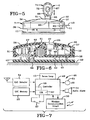
Fig. 5 is a diagrammatic side elevational view of one type of security device which can be used in the security system of the present invention. -
Fig. 6 is a cross-sectional view of the security device ofFig. 5 . -
Fig. 7 is a block diagram of the logic control circuit of the security device shown inFig. 5 . -
Fig. 8 is a plan view of the programmable smart key of the security system shown inFig. 1 . -
Fig. 9 is a cross-sectional view taken on line 9-9,Fig. 8 . -
Fig. 10 is a block diagram of the logic control circuit of the programmable key shown inFig. 8 . -
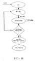
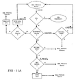
Figs. 11 ,11A and11B is a flow chart of the control circuitry of the programmable key shown inFig. 8 . -
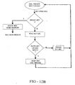
Figs. 12 ,12A and12B is a flow chart of the control circuitry of the programming station shown inFig. 2 . -
Fig. 13 is the flow chart of the control logic circuit for the security device shown inFig. 5 . -
Figs. 14, 15, 16 and 17 are diagrammatic views of other types of security devices which can be used with the security system of the present invention. - Similar numbers refer to similar parts throughout the drawings.
- The preferred embodiment of the improved security system of the present invention is indicated generally at 1, and is shown in
Fig. 1 . Security system 1 includes three main components, aprogramming station 3, a programmablesmart key 5 and an alarm module orsecurity device 7 which is adapted to be attached to an article ofmerchandise 9 by an attachment device such as acable 11, which preferably contains asense loop 13. -
Programming station 3 preferably is of the type shown and described in detail in a pending patent application entitled, Programming Station For A Security System For Protecting Merchandise filed concurrently herewith, the contents of which are incorporated herein by reference.Programming station 3 is shown inFigs. 2-4 and includes ahousing 15 formed by aninternal housing shell 16 preferably formed of an infrared clear plastic material to facilitate the transfer of infrared wireless communication waves, as discussed further below.Housing 15 furthermore includes atop cover plate 14 snap-fitted ontoshell 16 and a printedcircuit board 17 containing acontrol logic circuit 18 located therein.Logic control circuit 18 is shown in block diagram form inFig. 4 . -
Logic control circuit 18 includes amain controller 19 which preferably is a microprocessor, awireless communication circuit 20 and a security disarm code (SDC)memory 21 communicating withcontroller 19. Astatus display 22 which consists of threeLEDs 24 also is part ofcontrol circuit 18 and provides a visual indication of the status ofprogramming station 3 during and after the use ofprogramming station 3 for programming the SDC intosmart key 5.Housing shell 16 is secured to abase 24 byfasteners 25, which base can be secured to a supportingstructure 26 byfasteners 27.Wireless communication circuit 20, and in particular the transmission and receive components thereof, are aligned with akey receiving port 29 found inhousing shell 16, which port is adapted to receivesmart key 5 therein as shown inFig. 2 .Wireless communication circuit 20 and the various components thereof which are formed oncircuit board 17, in the preferred embodiment will be an infrared (IR) system, although radio frequency (RF) or other types of wireless communications could be used without affecting the concept of the invention. - A key-actuated
tumbler switch 31 is mounted inhousing 15 and is controlled by amechanical key 33 for activating the logic control circuit withinprogramming station 3 for programming asmart key 5 with the SDC as discussed further below. The particular circuitry oflogic control circuit 18 is shown in further detail in the above-referenced pending patent application, but could be other types of circuitry than that shown therein, which circuits are readily known to those skilled in the art for obtaining the features and results of the programming station as discussed further below. -
Programming station 3 preferably is powered by an external power supply such as a usual 120 volt electrical outlet readily found in a retail establishment. Preferably,station 3 will be secured to supportsurface 26 in a secure location, such as the store manager's office or similar protected environment. Likewise,activation key 33 will be kept in the possession of the store manager or other highly trusted employee to prevent the unauthorized use ofprogramming station 3. -
Alarm module 7, shown particularly inFigs. 5, 6 and 7 is one type of security device which can be used with the security system of the present invention.Alarm module 7 is of the type shown and described in greater detail in a pending patent application filed concurrently herewith entitled, Programmable Alarm Module And System For Protecting Merchandise, the contents of which are incorporated herein by reference.Alarm module 7 includes ahousing 35 preferably formed of plastic material which includes atop cover plate 36 which is snap-fitted on atop housing member 37, which in turn is secured to abottom housing member 38 by a plurality offasteners 39. Aligned posts 40 extending between a base 41 andbottom housing member 38 provides an open sound space 42 therebetween as shown inFig. 6 . - A
battery 44 is mounted in the interior ofhousing 35 and provides the source of power to a logic control circuit indicated generally at 46, and shown diagrammatically inFig. 7 , which circuit is formed on a printedcircuit board 48 mounted withinhousing 35.Logic control circuit 46 includes amain controller 49 and awireless communication circuit 50 which preferably is an IR system to match that ofprogramming station 3 as discussed above.Logic circuit 46 furthermore includes anaudible alarm 51 which preferably is a piezoelectric alarm mounted withinhousing 35 and communicating directly with sound space 42 as shown inFig. 6 .Circuit 46 further includes aSDC memory 53, an EAStag detector circuit 54, and one ormore sense loops 13. Aplunger switch 57 preferably is mounted withinbottom housing member 38 and includes a plunger 58 which engages asupport surface 59 on whichalarm module 7 is mounted, preferably by one or more attachment screws (not shown).Plunger switch 57 will actuatealarm 51 if the alarm module is illegally removed from the supporting surface. AnLED 61 is connected tologic control circuit 46 and extend through an opening formed intop housing member 37 andcover plate 36 to provide a visual indication of the status ofalarm module 7. - One or more connection jacks 63 are formed in
alarm module 7, for connecting anattachment cable 11 to alarmmodule 7 which cable contains asense loop 13.Sense loops 13 preferably are electrical conductors, fiber optic conductors or the like, which as shown inFig. 1 extends betweenalarm module 7 and an item ofmerchandise 9 to be protected thereby. Eachsense loop 13 is operationally connected tocontroller 49 so that should the integrity of the sense loop orcable 11 be compromised, such as by cutting of the cable, pulling it loose frommodule 7 or frommerchandise 9, it will soundaudible alarm 51, as well as provide a certain flashing pattern toLED 61. If desired,cable 11 could be connected to an automatic recoiler located withinmodule 7 without affecting the concept of the invention. The main feature is that the sense loop, and inparticular conductor 13 thereof, is optically or electrically connected tocontroller 49 and to an item ofmerchandise 9. - A
key receiving port 65 is formed intop cover plate 36 andtop housing member 37 ofhousing 35 adjacent alight pipe 67 to enhance the transmission of infrared signals whensmart key 5 is placed inport 65 and aligned with the transmitter andreceiver 69 mounted oncircuit board 48 belowport 65 as shown inFig. 6 . This facilitates the transmission of IR waves betweenkey 5 as discussed further below, and thewireless communication components 69 ofcommunication circuit 50. Further details and manner of operation ofalarm module 7 is shown and described in the above-referenced pending patent application, and it is readily understood that other types of circuit arrangements than that shown therein and shown inFig. 7 could be utilized to achieve the features ofalarm module 7 without affecting the concept of the invention. -
Smart key 5 is shown in detail inFigs. 8-10 .Key 5 includes ahousing 71 formed by upper and lowerplastic housing members hollow interior 74 in which is mounted abattery 75 and a printedcircuit board 76 containing a logic control circuit indicated generally at 77, and shown in block diagram form inFig. 10 . As shown inFig. 10 ,logic control circuit 77 will include awireless communication circuit 79 which preferably is IR operated so as to be compatible with the send and transmit components ofprogramming station 3 andalarm module 7. Acentral controller 80, which preferably is a type of microprocessor, controlswireless communication circuit 79, aSDC memory 81, aninternal timer 82 and anactivation counter 83.Logic control circuit 77 is energized by anactivation switch 85 which is mounted oncircuit board 76 and located beneath aflexible member 87 mounted inupper housing member 72, so that when depressed as shown by Arrow A,Fig. 9 , it will actuate the controller andlogic control circuit 77. - A
light pipe 89 preferably is mounted inupper housing member 72 in alignment with anLED 90 mounted oncircuit board 76.LED 90 provides a visual indication of the status and activation ofkey 5 as discussed further below. Alens 91 is mounted in anopening 92 ofhousing end 93, which preferably is a visible light filter to enhance the transmission and reception of infrared waves when the key interfaces withprogramming station 3 andalarm module 7. Again, details of the circuitry and components oflogic control circuit 77 are shown in the above-referenced patent application showing one example of a preferred circuit arrangement. However, it is readily understood that other circuit configurations can be utilized to achieve the results and features ofkey 5 than that shown and discussed above and in said pending patent application without affecting the concept of the invention. -
Fig. 1 best illustrates the preferred system and method of the present invention.Programming station 3 is actuated by use ofsecurity key 33 which is placed in a circularkey opening 95 which energizes the station.Smart key 5 is placed in key receivingport 29 andkey switch 85 is actuated by depressing downwardly onflexible member 87. This causeslogic control circuit 18 ofprogramming station 3 to randomly generate a unique SDC which is transmitted viawireless communication circuit 20 towireless communication circuit 79 ofkey 5 which stores the generated SDC inSDC memory 81 of the key. One or more of theLEDs 24 ofprogramming station 3 andLED 90 ofkey 5 will illuminate or flash to indicate thatstation 3 is activated and operating satisfactorily and that the SDC has been transmitted tokey 5. - In accordance with one of the features of the invention, the SDC which is initially generated by
programming station 3 is randomly generated and is unique tostation 3 and always remains with the station for subsequent use. Thus, when the first SDC is generated, this is the SDC that always stays withstation 3 and is subsequently programmed into one ormore keys 5.Key 5 now containing the SDC is taken to one ormore alarm modules 7 andkey end 93 is inserted intokey receiving port 65 as shown inFig. 5 .Key switch 85 is then actuated programming SDC via thewireless communication systems key 5 intoSDC memory 53 oflogic control circuit 46 ofalarm module 7.SDC memory 53 permanently stores this SDC in the programmed alarm module preferably for the life of the alarm module. Again, upon actuation ofkey switch 85,key LED 90 will flash as well asLED 61 ofalarm module 7 indicating that a successful programming of the alarm module with the SDC has occurred. - In accordance with another of the features of the invention, the SDC when stored in
memory 81 ofkey 5 will actuate atimer 82 for a predetermined time period, for example 96 hours. At the end of this time period, the SDC inmemory 81 will automatically be erased or invalidated bycontrol logic circuit 77 rendering the key inoperative if attempted to be used withalarm module 7. This prevents a key 5 from being stolen by a thief or dishonest employee and attempted to be reused after passage of this time period to disarm analarm module 7 in the same store from which the key has been stolen. Furthermore, since the SDC inkey 5 is unique to theparticular programming station 3 of that retail establishment, even ifkey 5 is taken to another store using the same type ofalarm module 7 when still within the valid time period of the SDC, the key it will not function with the other store's alarm module since it will have been programmed with a different SDC. Thus, programmedkey 5 prevents one of the main drawbacks of current security systems which uses various types of keys, since these prior security keys can always be used at one or more stores which use similar types of security devices, whether the key is a mechanical or magnetic actuated type of key. Thus, key 5 could only be used for a relatively short period of time by a thief or a dishonest employee and only in the particular store from which it was stolen. This preset time period could always be adjusted to 24 hours, 36 hours etc. without affecting the concept of the invention, although 96 hours has been found to be the preferred time period. Again, the transmission of the SDC betweenprogramming station 3 andkey 5 and betweenkey 5 andalarm module 7 is by the wireless communication transmission systems, preferably operating on IR or RF wavelengths. -
Counter 83 of keycontrol logic circuit 77 counts each time thatkey switch 85 is activated, whether when programmed with an SDC fromprogramming station 3 or disarming analarm module 7. After a predetermined number of activations, for example 55,000, counter 83 will causelogic control circuit 77 to inactivate the key rendering it inoperative for further use. This ensures thatbattery 75 always has a sufficient charge for the transmission of the SDC between the key andstation 3 andmodules 7. - In order to disarm
alarm module 7, a validly programmed key 5 which is still within its active time period, will be placed intokey receiving port 65 as shown inFig. 5 and switch 85 is energized by depressing onmember 87.Wireless communication systems alarm 51 enablingcable 11 to be removed fromobject 9 or from thealarm module jack 63 for sale ofitem 9 to a customer or for attachment of a new or different type of merchandise to the alarm module. After the desired product manipulation has occurred,key 5 is then used to rearm the alarm module. Again,key LED 90 and alarm modules LED 61 will flash in various patterns to indicate that the disarming has occurred and then subsequently that the rearming has occurred. Again,SDC memory 53 ofalarm module 7 must read the same SDC code generated bykey 5 in order to disarmmodule 7. If a different SDC is sensed byalarm module 7 than that stored inmemory 53,module 7 will soundalarm 51 indicating that an incorrect key is being used. Likewise, if the SDC had been removed from the key bytimer 82, the key will not operate or disarm thealarm module 7 and will provide a flashing signal that the disarming has not occurred and that an uncoded key is being used. - Furthermore, as shown in
Fig. 6 , the formation of sound space 42 and its direct communication withpiezo alarm 51 will provide a greater dB level for the same size alarm than that occurs in prior alarm modules wherein the piezo alarm is mounted entirely within the alarm module housing.Alarm module 7, and in particularlogic control circuit 46, contains an end of life (EOL) 97 or lifetime timer which is actuated whenalarm module 7 is first energized. This timer has been preset at the factory for a specific time period, for example 3 or five years, depending upon the particular size ofbattery 44 contained therein. At the end of this lifetime period,control logic circuit 46 will deactivatealarm module 7 preventing its subsequent arming with an SDC. This ensures that the battery has sufficient power throughout the useful life of the alarm module. Furthermore, acounter 98 is provided in the alarm module which records the length of time thatalarm 51 is operated since the alarm results in additional drain to the battery charge. This alarm time is then subtracts from the EOL period by a certain formulation. Again, this ensures thatbattery 44 has sufficient power to satisfactorily operatealarm module 7 even though the audible alarm has been used a number of times during its life. - An near end-of-life (NEOL) feature is also provided in
control logic circuit 46 which will provide a visual signal such as particular flashing pattern ofLED 61 and a different non-alarming chirping sound fromalarm 51, when the end-of-life time out is approaching, for example five days before the end-of-life timer completely inactivates the alarm module circuitry. - Further details of the operation of
logic control circuitry 77 ofprogrammable key 5 is shown inFigs. 11-11B .Figs. 12-12B shows additional details of the manner and method of operation of thelogic control circuitry 18 ofprogramming station 3, withFig. 13 showing the manner of operation of thelogic control circuitry 46 ofalarm module 7. The sequence of events and actions taken by these various components and shown in the flow chart ofFigs. 11-13 is readily understood and followed by one skilled in the art. -
Figs. 14-17 show examples of four other types of security devices which could be used in the security system and method of the present invention.Fig. 14 shows a product display security device indicated at 100 for displaying and protecting an item ofmerchandise 101 attached to acable 102 which would contain a sense loop. A smartkey receiving port 103 is formed in thesecurity device housing 104, which when akey 5 is inserted therein would initially program and then subsequently disarmsecurity device 100.Fig. 15 shows a type of garmenttag security device 105 which is formed with a smartkey receiving port 106 which is used to deactivate the security tag to enable apin alarm 107 to be removed from agarment 108.Fig. 16 shows another type of cablealarm security device 109 which is connected about an item ofmerchandise 110 by acable 111.Cable 111 contains a sense loop and will be formed with a smartkey receiving port 112 therein in order to deactivatesecurity device 109 enabling it to be removed from protecteditem 110. Still another type of security device indicated generally at 115, is shown inFig. 17 which includes a plurality ofcables 116 which extend about anitem 117 to be protected thereby. It is readily understood thatcables 116 preferably contain sense loops and are tightened aboutpackage 117 by aratchet mechanism 118. A smartkey receiving port 119 is provided, along with a logic control circuit etc. within ahousing 120 containing the ratchet mechanism.Figs. 14-17 merely show other examples of how the security system of the present invention and its method of operation can be utilized and that it need not be limited to theparticular alarm module 7 shown and described above. - In summary, the improved security system of the present invention provides a system which can be used in numerous retail establishments, which utilizes a smart key as the main component, which even if stolen, cannot be used even in the store of its origin after a predetermined time period to disarm an alarm module, and can never be used in another store to disarm a security device since it is programmed with a SDC unique to that particular store, and that the SDC is initially randomly generated by a programming station used only by that store. The smart key contains the internal timer which will deactivate a validly stored SDC after a predetermined time period thereby rendering the key completely useless even in the store of its origin after this time period. The key merely has to be taken back to the programming station which can be maintained in a secure location enabling an authorized clerk to reprogram the key with the same SDC for subsequent use with the various alarm modules in the store, all of which will have been programmed from one of the smart keys with the unique SDC for that store. Also,
programming station 3,smart key 5 andalarm module 7 each have various types of visual indicators and/or alarms which advise a store clerk of the status of the these components, and which will alert the clerk if an item of merchandise and/or alarm module is being tampered. Also,programming station 3 will deactivate a stored SDC in a key if it is the wrong SDC when attempting to reprogram the key atprogramming station 3. Also alarmmodule 7 will sound an alarm if a key containing a wrong SDC is attempted to be used on an alarm module. In addition to these features, each of the individual components have various timing circuits, control circuits and visual indicating circuits all of which are part of the internal logic control circuits contained in the components, which features are described in further detail in the above-referenced pending patent applications covering each of these components. - Another feature which may be incorporated into the present invention is the use of a "master" key and "employee" keys in order to provide an additional layer of security to the security system of a particular retail store. In this dual key system, the random number generator contained in the logic control circuit of the programming station will only generate the SDC when the master key is presented to the station and a limited access switch is activated. This master key then can be used to program the SDC into the various alarming modules, as well as the employee keys which are subsequently programmed with the SDC by the programming station once the SDC is generated by using the master key.
- The use of the master key enables the store manager to change the SDC of the programming station which then is subsequently used by the employee keys and the alarm modules throughout the store, if for some reason the manager believes that the original SDC was compromised. Should a new SDC be generated by the master key and then reprogrammed into the employee keys, the control logic circuit of the alarm module, will be provided with a means of recognizing both the old and the new SDC of a key when in wireless communication therewith. This will enable the alarm module to accept the new SDC to disarm the alarm module without activating the audible alarm which would occur as discussed above, when the alarm module reads the use of a key having a wrong SDC programmed therein.
- This dual key system would increase the complexity of the various logic control circuits in the smart keys, programming station and alarm modules, but would provide an additional layer of security should the location using the improved security system of the present invention desire such an increased level of security. However; the preferred embodiment described previously is believed to provide very adequate security protection for its merchandise system by the use of only a single key. However, the dual key system can be used without departing from the concept of the present invention.
- Although the above description refers to the security code being a disarm code, it is understood that the code can activate and control other functions and features of the security device such as unlocking the device from the product, shutting off an alarm etc. without departing from the concept of the invention. Likewise, the various components of the logic circuit and resulting flow charts can easily be modified by one skilled in the art to achieve the same results. Also, the security code can be preset in the programming station at the factory or chosen by the customer, and if desired, be changed later by the customer, also without affecting the concept of the invention.
- In the foregoing description, certain terms have been used for brevity, clearness, and understanding. No unnecessary limitations are to be implied therefrom beyond the requirement of the prior art because such terms are used for descriptive purposes and are intended to be broadly construed.
- Moreover, the description and illustration of the invention is an example and the invention is not limited to the exact details shown or described.
Claims (14)
- A security system (1) for protecting an item of merchandise comprising:a keying device, namely a programmable key (5);a programming station (3) for generating a security code and for programming the security code into the key (5); andan alarm module (7) for attachment to the item of merchandise (9), said alarm module (7) being programmable with the security code by the key (5) and being disarmable by the key (5) upon matching the security code programmed into the key (5) by the programming station (3) with the security code programmed into the alarm module (7) by the key (5);whereby the key (5) includes an internal timer (82) which automatically invalidates the security code in the key (5) after a preset period of time.
- The security system defined in claim 1, wherein the programming station (3) includes a wireless interface for generating the security code in the key (5).
- The security system defined in claim 2, wherein the wireless interface is IR or RF communications.
- The security device defined in claim 1, wherein the timer (82) is a resetable timer upon receiving the security code from the programming station (3).
- The security system defined in claim 1, wherein the key (5) includes a counter (83) which counts the number of activations of the key.
- The security device defined in claim 5, wherein the counter (83) permanently inactivates the key (5) after counting a predetermined number of activations.
- The security system defined in claim 6, wherein the timer (82) causes an indicator to be activated advising that the key (5) has a certain time period before being permanently inactivated.
- The security system defined in claim 1, wherein the alarm module (7) contains an audible alarm (51); and in which a sense loop (13) connects the alarm module (7) to the item of merchandise (9); and in which the alarm is activated upon the integrity of the sense loop (13) being compromised.
- A method of protecting an object, namely an item of merchandise, including the steps of:attaching an alarm module to the item of merchandise;programming a keying device, namely a programmable key, with a security code;programming the security code into the alarm module from the key;disarming the alarm module by verifying the security code in the key with the security code in the alarm module by wireless communication between the key and alarm module; and automaticallyinvalidating the security code in the key after a period of time to prevent subsequent disarming of the alarm module by said key unless the security code is refreshed in the key within said period of time.
- The method defined in claim 9, including the step of counting the number of activations of the key upon refreshing the key with the security code and disarming the alarm module by communication between the key and alarm module.
- The method defined in claim 10, including the step of permanently inactivating the key after a certain number of activations.
- The method defined in claim 11, including the step of providing a signal that the number of activations of the key is approaching the number which permanently inactivates the key.
- The method defined in claim 9, including the step of sounding an alarm in the alarm module when the integrity of the alarm module is compromised.
- The method defined in claim 9, including the steps of providing a programming station for generating the security code; and providing a wireless interface between the programming station and key for programming the key with the security code.
Applications Claiming Priority (3)
| Application Number | Priority Date | Filing Date | Title |
|---|---|---|---|
| US75390805P | 2005-12-23 | 2005-12-23 | |
| US11/639,102 US7737846B2 (en) | 2005-12-23 | 2006-12-14 | Security system and method for protecting merchandise |
| PCT/US2006/048518 WO2007075739A2 (en) | 2005-12-23 | 2006-12-20 | Security system and method for protecting merchandise |
Publications (3)
| Publication Number | Publication Date |
|---|---|
| EP1963931A2 EP1963931A2 (en) | 2008-09-03 |
| EP1963931A4 EP1963931A4 (en) | 2010-06-16 |
| EP1963931B1 true EP1963931B1 (en) | 2011-04-06 |
Family
ID=38218550
Family Applications (1)
| Application Number | Title | Priority Date | Filing Date |
|---|---|---|---|
| EP06845868A Active EP1963931B1 (en) | 2005-12-23 | 2006-12-20 | Security system and method for protecting merchandise |
Country Status (10)
| Country | Link |
|---|---|
| US (2) | US7737846B2 (en) |
| EP (1) | EP1963931B1 (en) |
| JP (1) | JP2009521748A (en) |
| CN (3) | CN101894439A (en) |
| AT (1) | ATE504901T1 (en) |
| AU (1) | AU2006331809B2 (en) |
| DE (1) | DE602006021230D1 (en) |
| ES (1) | ES2364582T3 (en) |
| HK (1) | HK1174428A1 (en) |
| WO (1) | WO2007075739A2 (en) |
Families Citing this family (66)
| Publication number | Priority date | Publication date | Assignee | Title |
|---|---|---|---|---|
| US20110276609A1 (en) | 2001-12-27 | 2011-11-10 | Denison William D | Method for Controlling and Recording the Security of an Enclosure |
| US20070090917A1 (en) * | 2005-10-20 | 2007-04-26 | Michael Boyden Parnaby | Vehicle dealership security system |
| US20110254661A1 (en) | 2005-12-23 | 2011-10-20 | Invue Security Products Inc. | Programmable security system and method for protecting merchandise |
| US7737846B2 (en) * | 2005-12-23 | 2010-06-15 | Invue Security Products Inc. | Security system and method for protecting merchandise |
| US20090223908A1 (en) * | 2008-03-07 | 2009-09-10 | Wal-Mart Stores, Inc. | Device Display Unit |
| US10373456B2 (en) | 2009-01-10 | 2019-08-06 | Mobile Tech, Inc. | Display for hand-held electronics |
| US20140159898A1 (en) | 2010-06-21 | 2014-06-12 | Mobile Technologies, Inc. | Display for hand-held electronics |
| US11344140B2 (en) | 2009-01-10 | 2022-05-31 | Mobile Tech, Inc. | Display for hand-held electronics |
| US8698617B2 (en) | 2010-06-21 | 2014-04-15 | Mobile Tech, Inc. | Display for hand-held electronics |
| US8542119B2 (en) * | 2009-01-13 | 2013-09-24 | Invue Security Products Inc. | Combination non-programmable and programmable key for security device |
| CN102439642A (en) * | 2009-03-12 | 2012-05-02 | 关卡系统公司 | Disposable cable lock and detachable alarm module |
| US20110050439A1 (en) * | 2009-08-27 | 2011-03-03 | Robert Wang | Protector having a dual-warning outer casing |
| EP2536906A1 (en) * | 2010-02-16 | 2012-12-26 | Enneffe S.r.l. | Multi -function anti-theft system |
| US8640509B2 (en) | 2010-04-30 | 2014-02-04 | Checkpoint Systems, Inc. | Security assembly for attachment to an object |
| US8698618B2 (en) * | 2010-06-21 | 2014-04-15 | Mobile Tech, Inc. | Display for hand-held electronics |
| US20120047972A1 (en) * | 2010-09-01 | 2012-03-01 | Invue Security Products Inc. | Electronic key for merchandise security device |
| US8872659B2 (en) * | 2011-01-17 | 2014-10-28 | Invue Security Products Inc. | Merchandise display security device for headphones |
| US8810437B2 (en) | 2011-02-02 | 2014-08-19 | Mapquest, Inc. | Systems and methods for generating electronic map displays with points-of-interest information based on reference locations |
| WO2012109376A1 (en) * | 2011-02-08 | 2012-08-16 | Dci Marketing, Inc. | Powered security display device |
| US9092960B2 (en) | 2011-05-05 | 2015-07-28 | Mobile Tech, Inc. | Retail security system |
| US8878673B2 (en) * | 2011-05-19 | 2014-11-04 | Invue Security Products Inc. | Systems and methods for protecting retail display merchandise from theft |
| US11017656B2 (en) | 2011-06-27 | 2021-05-25 | Invue Security Products Inc. | Programmable security system and method for protecting merchandise |
| US8941388B2 (en) * | 2011-08-13 | 2015-01-27 | Tracthat Llc | Auto-calibrating proximity sensor for retail display security system |
| CN204060210U (en) | 2011-09-29 | 2014-12-31 | Invue安全产品公司 | For the cabinet lock used together with programmable electronic key |
| US8629772B2 (en) | 2011-12-06 | 2014-01-14 | Southern Imperial, Inc. | Signal emitting retail device |
| US9318008B2 (en) | 2011-12-06 | 2016-04-19 | Southern Imperial, Inc. | Signal emitting retail device |
| WO2013177037A1 (en) | 2012-05-21 | 2013-11-28 | Invue Security Products Inc. | Cabinet lock key with audio indicators |
| US8884761B2 (en) | 2012-08-21 | 2014-11-11 | Souther Imperial, Inc. | Theft detection device and method for controlling |
| US9324220B2 (en) | 2012-08-21 | 2016-04-26 | Southern Imperial, Inc. | Theft detection device and method for controlling same |
| US9163433B2 (en) * | 2012-10-31 | 2015-10-20 | Invue Security Products Inc. | Display stand for a tablet computer |
| US9760116B2 (en) | 2012-12-05 | 2017-09-12 | Mobile Tech, Inc. | Docking station for tablet device |
| US10424882B2 (en) | 2013-05-09 | 2019-09-24 | Invue Security Products Inc. | Security connector |
| WO2014186566A1 (en) * | 2013-05-17 | 2014-11-20 | Invue Security Products Inc. | Alarming cables, assemblies, and systems |
| WO2015026918A1 (en) * | 2013-08-23 | 2015-02-26 | Invue Security Products Inc. | Quick release security device |
| US20150061831A1 (en) * | 2013-08-28 | 2015-03-05 | Invue Security Products Inc. | Key and security device |
| US20160222699A1 (en) * | 2013-09-17 | 2016-08-04 | Invue Security Products Inc. | Smart device for use with an electronic key |
| US9299232B2 (en) | 2013-12-20 | 2016-03-29 | Checkpoint Systems, Inc. | Security device with dual use transformer |
| US10312731B2 (en) | 2014-04-24 | 2019-06-04 | Westrock Shared Services, Llc | Powered shelf system for inductively powering electrical components of consumer product packages |
| WO2016069344A1 (en) * | 2014-10-31 | 2016-05-06 | Invue Security Products Inc. | Security connector |
| EP3221854A4 (en) | 2014-11-18 | 2018-08-01 | InVue Security Products, Inc. | Key and security device |
| BR112017013997B1 (en) * | 2014-12-29 | 2022-06-28 | Invue Security Products Inc | MERCHANDISE SECURITY SYSTEM AND METHOD FOR PROTECTING AN THEFT-SUSCEPTIBLE MERCHANDISE |
| US9460594B1 (en) * | 2015-03-09 | 2016-10-04 | Sennco Solutions Inc. | Apparatus, system and method for positioning a cable with a sensor by a rotatable cable assembly |
| EP3272193A4 (en) | 2015-09-30 | 2018-06-27 | InVue Security Products, Inc. | Gang charger, shroud, and dock for portable electronic devices |
| US10251144B2 (en) | 2015-12-03 | 2019-04-02 | Mobile Tech, Inc. | Location tracking of products and product display assemblies in a wirelessly connected environment |
| US10728868B2 (en) | 2015-12-03 | 2020-07-28 | Mobile Tech, Inc. | Remote monitoring and control over wireless nodes in a wirelessly connected environment |
| US10517056B2 (en) | 2015-12-03 | 2019-12-24 | Mobile Tech, Inc. | Electronically connected environment |
| US11109335B2 (en) | 2015-12-03 | 2021-08-31 | Mobile Tech, Inc. | Wirelessly connected hybrid environment of different types of wireless nodes |
| WO2017112749A1 (en) * | 2015-12-22 | 2017-06-29 | Invue Security Products Inc. | Merchandise security container |
| WO2017181140A1 (en) | 2016-04-15 | 2017-10-19 | Mobile Tech, Inc. | Gateway-based anti-theft security system and method |
| US10101770B2 (en) | 2016-07-29 | 2018-10-16 | Mobile Tech, Inc. | Docking system for portable computing device in an enclosure |
| US10121341B2 (en) | 2017-01-23 | 2018-11-06 | Southern Imperial Llc | Retail merchandise hook with radio transmission |
| CN106600879B (en) * | 2017-02-04 | 2019-04-16 | 常州市亚森电子有限公司 | A kind of electronic tag and theft preventing method based on multiple safety |
| CN107993386B (en) * | 2017-12-12 | 2020-02-11 | 吴永 | Article safety device and system |
| CN108416875A (en) * | 2018-01-25 | 2018-08-17 | 阿里巴巴集团控股有限公司 | A kind of showing stand of object, the processing method of data, device, equipment and system |
| US10885753B2 (en) | 2018-03-21 | 2021-01-05 | Fasteners For Retail, Inc. | Anti-theft device with remote alarm feature |
| US11363894B2 (en) | 2019-04-05 | 2022-06-21 | Fasteners For Retail, Inc. | Anti-theft pusher with incremental distance detection |
| US10993550B2 (en) | 2018-03-21 | 2021-05-04 | Fasteners For Retail, Inc. | Anti-theft retail merchandise pusher with remote alarm feature |
| WO2020023366A1 (en) * | 2018-07-23 | 2020-01-30 | Invue Security Products Inc. | Counter detacher system and method |
| US20220070620A1 (en) | 2018-10-25 | 2022-03-03 | Mobile Tech, Inc | Proxy nodes for expanding the functionality of nodes in a wirelessly connected environment |
| US10614682B1 (en) | 2019-01-24 | 2020-04-07 | Mobile Tech, Inc. | Motion sensing cable for tracking customer interaction with devices |
| BR112021003117A2 (en) * | 2019-05-07 | 2021-11-16 | Invue Security Products Inc | Security systems and methods for displaying merchandise |
| US11704950B2 (en) | 2019-08-08 | 2023-07-18 | Skeleton Key Systems, LLC | Retail security system |
| CN112805636A (en) * | 2019-09-13 | 2021-05-14 | 开利公司 | Building access system with programmed door locks |
| US11087601B1 (en) | 2020-04-02 | 2021-08-10 | Fasteners For Retail, Inc | Anti-theft device with cable attachment |
| USD956607S1 (en) | 2020-04-16 | 2022-07-05 | Fasteners For Retail, Inc. | Security tag holder |
| US20220262181A1 (en) * | 2021-02-12 | 2022-08-18 | Invue Security Products Inc. | Merchandise display security systems and methods |
Family Cites Families (72)
| Publication number | Priority date | Publication date | Assignee | Title |
|---|---|---|---|---|
| US3493955A (en) * | 1968-04-17 | 1970-02-03 | Monere Corp | Method and apparatus for detecting the unauthorized movement of articles |
| US3685037A (en) * | 1970-10-06 | 1972-08-15 | Anthony B Bennett | Alarm system for business machines |
| US4573042A (en) * | 1983-03-14 | 1986-02-25 | Sensormatic Electronics Corporation | Electronic article surveillance security system |
| US4686513A (en) * | 1985-09-30 | 1987-08-11 | Sensormatic Electronics Corporation | Electronic surveillance using self-powered article attached tags |
| US5005125A (en) * | 1986-02-28 | 1991-04-02 | Sensormatic Electronics Corporation | Surveillance, pricing and inventory system |
| AU600451B2 (en) * | 1986-10-21 | 1990-08-16 | Toyoji Gomi | Anti-shoplifting system |
| GB8705892D0 (en) * | 1987-03-12 | 1987-04-15 | Security Services Plc | Keys |
| DE3733808A1 (en) * | 1987-10-07 | 1989-05-11 | T E C Computer Gmbh | DEVICE FOR MONITORING PROPERTIES AND / OR PERSONS |
| US4853692A (en) * | 1987-12-07 | 1989-08-01 | Wolk Barry M | Infant security system |
| US4980671A (en) * | 1989-04-26 | 1990-12-25 | Guardian Technologies, Inc. | Remote confinement system with timed tamper signal reset |
| US6122704A (en) * | 1989-05-15 | 2000-09-19 | Dallas Semiconductor Corp. | Integrated circuit for identifying an item via a serial port |
| US5182543A (en) * | 1990-09-12 | 1993-01-26 | Board Of Trustees Operating Michigan State University | Miniaturized data communication and identification system |
| US5151684A (en) * | 1991-04-12 | 1992-09-29 | Johnsen Edward L | Electronic inventory label and security apparatus |
| US5170431A (en) * | 1991-09-20 | 1992-12-08 | Mas-Hamilton Group | Electronic bolt lock with enhanced security features |
| US5367289A (en) * | 1991-11-27 | 1994-11-22 | Sensormatic Electronics Corporation | Alarm tag for an electronic article surveillance system |
| US5245317A (en) * | 1991-12-18 | 1993-09-14 | Duncan Chidley | Article theft detection apparatus |
| US5570080A (en) * | 1992-04-24 | 1996-10-29 | Toshio Inoue | Theft prevention tab device having alarm mechanism housed therein |
| JP2723452B2 (en) * | 1993-08-23 | 1998-03-09 | 株式会社多川商事 | Self-sounding tag alarm device |
| WO1995006923A1 (en) * | 1993-08-31 | 1995-03-09 | Kubota Corporation | Antitheft device |
| EP0667600B1 (en) * | 1993-08-31 | 1999-10-20 | Kubota Corporation | Antitheft device |
| EP1050860A1 (en) * | 1994-07-29 | 2000-11-08 | Kubota Corporation | Radio wave receiving signaling device |
| ZA957405B (en) * | 1994-09-14 | 1996-04-17 | Diebold Inc | Electronic security system |
| US6359547B1 (en) * | 1994-11-15 | 2002-03-19 | William D. Denison | Electronic access control device |
| FR2728991A1 (en) * | 1994-12-28 | 1996-07-05 | Robin Veronique Roulleaux | METHOD AND DEVICE FOR THE DETECTION, IDENTIFICATION AND PROTECTION OF PROPERTY, IN PARTICULAR AGAINST THEFT |
| JP3011634B2 (en) | 1995-04-06 | 2000-02-21 | 三洋電機株式会社 | Warning sound generator |
| JPH08279083A (en) * | 1995-04-07 | 1996-10-22 | Alps Electric Co Ltd | Robbery monitor device with alarm |
| JPH08287368A (en) * | 1995-04-10 | 1996-11-01 | Alps Electric Co Ltd | Theft monitoring device with alarm |
| US5836002A (en) * | 1995-06-01 | 1998-11-10 | Morstein; Jason | Anti-theft device |
| EP0768629A1 (en) * | 1995-10-13 | 1997-04-16 | MATRIX S.a.s. di G. DE ZORZI e C. | An alarm system for articles to be confined within a given range |
| US5793290A (en) * | 1996-02-29 | 1998-08-11 | Rf Technologies, Inc. | Area security system |
| US5748083A (en) * | 1996-03-11 | 1998-05-05 | Security Solutions Plus | Computer asset protection apparatus and method |
| JP3142775B2 (en) * | 1996-05-16 | 2001-03-07 | セコム株式会社 | Alarm tag remover |
| AUPO085596A0 (en) * | 1996-07-05 | 1996-07-25 | Integrated Silicon Design Pty Ltd | Presence and data labels |
| US6118367A (en) * | 1996-11-29 | 2000-09-12 | Yoshikawa Rf Systems Co., Ltd. | Data carrier system |
| US6255951B1 (en) * | 1996-12-20 | 2001-07-03 | Carlos De La Huerga | Electronic identification bracelet |
| US6346886B1 (en) * | 1996-12-20 | 2002-02-12 | Carlos De La Huerga | Electronic identification apparatus |
| US6700479B2 (en) * | 1997-01-29 | 2004-03-02 | Directed Electronics, Inc. | Vehicle security system having advanced wireless function-programming capability |
| US6043744A (en) * | 1997-08-11 | 2000-03-28 | Sanyo Electric Co., Ltd. | Antitheft system |
| US5982283A (en) * | 1997-09-01 | 1999-11-09 | Sanyo Electric Co., Ltd. | Antitheft system |
| US6037879A (en) * | 1997-10-02 | 2000-03-14 | Micron Technology, Inc. | Wireless identification device, RFID device, and method of manufacturing wireless identification device |
| DE19745953C2 (en) * | 1997-10-17 | 2002-12-05 | Anatoli Stobbe | Anti-theft system and method for automatic detection and identification of an anti-theft tag by a base station |
| EP0958443A1 (en) * | 1997-11-05 | 1999-11-24 | Medeco Security Locks, Inc. | Electronic lock in cylinder of standard lock |
| NO981723D0 (en) * | 1998-04-16 | 1998-04-16 | Instrutek Holding As | System for monitoring and controlling objects or persons |
| US5955951A (en) * | 1998-04-24 | 1999-09-21 | Sensormatic Electronics Corporation | Combined article surveillance and product identification system |
| US5942978A (en) * | 1998-04-24 | 1999-08-24 | Sensormatic Electronics Corporation | Wireless transmitter key for EAS tag detacher unit |
| US6275141B1 (en) * | 1998-05-11 | 2001-08-14 | Gerhard Walter | Single-key security system |
| US6304181B1 (en) * | 1998-10-20 | 2001-10-16 | Sanyo Electronics Co., Ltd | Antitheft system and monitoring system |
| US6137414A (en) * | 1998-11-30 | 2000-10-24 | Exi Wireless Systems Inc. | Asset security tag |
| GB9914711D0 (en) * | 1999-06-23 | 1999-08-25 | Leck Michael J | Electronic seal,methods and security system |
| AU8034900A (en) * | 1999-08-27 | 2001-03-26 | Alpha Security Products, Inc. | Security container having mechanical and magnetic locking mechanism |
| US6300873B1 (en) * | 1999-09-16 | 2001-10-09 | Atlantes Services, Inc. | Locking mechanism for use with one-time access code |
| US6677852B1 (en) * | 1999-09-22 | 2004-01-13 | Intermec Ip Corp. | System and method for automatically controlling or configuring a device, such as an RFID reader |
| US6512457B2 (en) * | 1999-11-15 | 2003-01-28 | Hector Irizarry | Monitoring device adapted for use with an electronic article surveillance system |
| JP3789721B2 (en) * | 2000-03-31 | 2006-06-28 | 三洋電機株式会社 | Anti-theft device |
| JP4252713B2 (en) * | 2000-08-31 | 2009-04-08 | センサーマチック・エレクトロニックス・コーポレーション | Anti-theft device |
| US6700489B1 (en) | 2000-11-27 | 2004-03-02 | Sensormatic Electronics Corporation | Handheld cordless deactivator for electronic article surveillance tags |
| US6535130B2 (en) * | 2001-04-25 | 2003-03-18 | Sensormatic Electronics Corporation | Security apparatus for electronic article surveillance tag |
| CN2489423Y (en) * | 2001-07-03 | 2002-05-01 | 何方奇 | Disposable used good antifalse label |
| US6961000B2 (en) * | 2001-07-05 | 2005-11-01 | Amerasia International Technology, Inc. | Smart tag data encoding method |
| EP1493135A4 (en) * | 2002-04-11 | 2006-06-07 | Sensormatic Electronics Corp | System and method for managing assets using a portable combined electronic article surveillance system and barcode scanner |
| US7002467B2 (en) * | 2002-05-02 | 2006-02-21 | Protex International Corporation | Alarm interface system |
| US6864792B2 (en) | 2002-09-06 | 2005-03-08 | Sensormatic Electronics Corporation | Portable electronic security key for electronic article surveillance device |
| US7102509B1 (en) * | 2003-01-11 | 2006-09-05 | Global Tel★Link Corporation | Computer interface system for tracking of radio frequency identification tags |
| WO2005027694A2 (en) * | 2003-09-12 | 2005-03-31 | Alpha Security Products, Inc. | Alarming merchandise display system |
| US7239238B2 (en) * | 2004-03-30 | 2007-07-03 | E. J. Brooks Company | Electronic security seal |
| US20050242962A1 (en) * | 2004-04-29 | 2005-11-03 | Lind Michael A | Tag device, luggage tag, and method of manufacturing a tag device |
| US20070131005A1 (en) * | 2005-12-14 | 2007-06-14 | Checkpoint Systems, Inc. | Systems and methods for providing universal security for items |
| US7737845B2 (en) * | 2005-12-23 | 2010-06-15 | Invue Security Products Inc. | Programmable key for a security system for protecting merchandise |
| US7737846B2 (en) * | 2005-12-23 | 2010-06-15 | Invue Security Products Inc. | Security system and method for protecting merchandise |
| US7737844B2 (en) * | 2005-12-23 | 2010-06-15 | Invue Security Products Inc. | Programming station for a security system for protecting merchandise |
| US7737843B2 (en) * | 2005-12-23 | 2010-06-15 | Invue Security Products Inc. | Programmable alarm module and system for protecting merchandise |
| US7667601B2 (en) * | 2006-02-23 | 2010-02-23 | Vira Manufacturing, Inc. | Apparatus for secure display, interactive delivery of product information and charging of battery-operated hand held electronic devices |
-
2006
- 2006-12-14 US US11/639,102 patent/US7737846B2/en active Active
- 2006-12-20 WO PCT/US2006/048518 patent/WO2007075739A2/en active Application Filing
- 2006-12-20 EP EP06845868A patent/EP1963931B1/en active Active
- 2006-12-20 AU AU2006331809A patent/AU2006331809B2/en not_active Ceased
- 2006-12-20 AT AT06845868T patent/ATE504901T1/en not_active IP Right Cessation
- 2006-12-20 DE DE602006021230T patent/DE602006021230D1/en active Active
- 2006-12-20 JP JP2008547462A patent/JP2009521748A/en not_active Withdrawn
- 2006-12-20 ES ES06845868T patent/ES2364582T3/en active Active
- 2006-12-20 CN CN2010102417425A patent/CN101894439A/en active Pending
- 2006-12-20 CN CN200680048187.6A patent/CN101583983B/en not_active Expired - Fee Related
- 2006-12-20 CN CN201210253455.5A patent/CN102789670B/en active Active
-
2010
- 2010-04-29 US US12/770,321 patent/US7969305B2/en active Active
-
2013
- 2013-02-07 HK HK13101716.6A patent/HK1174428A1/en not_active IP Right Cessation
Also Published As
| Publication number | Publication date |
|---|---|
| EP1963931A2 (en) | 2008-09-03 |
| CN101583983A (en) | 2009-11-18 |
| WO2007075739A3 (en) | 2008-12-04 |
| ATE504901T1 (en) | 2011-04-15 |
| US20100238031A1 (en) | 2010-09-23 |
| CN102789670A (en) | 2012-11-21 |
| JP2009521748A (en) | 2009-06-04 |
| CN101894439A (en) | 2010-11-24 |
| AU2006331809A1 (en) | 2007-07-05 |
| CN102789670B (en) | 2014-12-17 |
| AU2006331809B2 (en) | 2011-03-10 |
| ES2364582T3 (en) | 2011-09-07 |
| EP1963931A4 (en) | 2010-06-16 |
| HK1174428A1 (en) | 2013-06-07 |
| US7737846B2 (en) | 2010-06-15 |
| US7969305B2 (en) | 2011-06-28 |
| CN101583983B (en) | 2014-07-16 |
| WO2007075739A2 (en) | 2007-07-05 |
| DE602006021230D1 (en) | 2011-05-19 |
| US20070159328A1 (en) | 2007-07-12 |
Similar Documents
| Publication | Publication Date | Title |
|---|---|---|
| EP1963931B1 (en) | Security system and method for protecting merchandise | |
| EP1971970B1 (en) | Programming station for a security system for protecting merchandise | |
| US10600313B2 (en) | Programmable security system and method for protecting merchandise | |
| EP1964082B1 (en) | Programmable alarm module and system for protecting merchandise | |
| US7737845B2 (en) | Programmable key for a security system for protecting merchandise |
Legal Events
| Date | Code | Title | Description |
|---|---|---|---|
| PUAI | Public reference made under article 153(3) epc to a published international application that has entered the european phase |
Free format text: ORIGINAL CODE: 0009012 |
|
| 17P | Request for examination filed |
Effective date: 20080428 |
|
| AK | Designated contracting states |
Kind code of ref document: A2 Designated state(s): AT BE BG CH CY CZ DE DK EE ES FI FR GB GR HU IE IS IT LI LT LU LV MC NL PL PT RO SE SI SK TR |
|
| AX | Request for extension of the european patent |
Extension state: AL BA HR MK RS |
|
| R17D | Deferred search report published (corrected) |
Effective date: 20081204 |
|
| RIC1 | Information provided on ipc code assigned before grant |
Ipc: G08B 13/12 20060101AFI20090107BHEP |
|
| A4 | Supplementary search report drawn up and despatched |
Effective date: 20100518 |
|
| GRAP | Despatch of communication of intention to grant a patent |
Free format text: ORIGINAL CODE: EPIDOSNIGR1 |
|
| RIC1 | Information provided on ipc code assigned before grant |
Ipc: G08B 13/12 20060101AFI20101015BHEP |
|
| DAX | Request for extension of the european patent (deleted) | ||
| GRAS | Grant fee paid |
Free format text: ORIGINAL CODE: EPIDOSNIGR3 |
|
| GRAA | (expected) grant |
Free format text: ORIGINAL CODE: 0009210 |
|
| AK | Designated contracting states |
Kind code of ref document: B1 Designated state(s): AT BE BG CH CY CZ DE DK EE ES FI FR GB GR HU IE IS IT LI LT LU LV MC NL PL PT RO SE SI SK TR |
|
| REG | Reference to a national code |
Ref country code: GB Ref legal event code: FG4D |
|
| REG | Reference to a national code |
Ref country code: CH Ref legal event code: EP |
|
| REG | Reference to a national code |
Ref country code: IE Ref legal event code: FG4D |
|
| REF | Corresponds to: |
Ref document number: 602006021230 Country of ref document: DE Date of ref document: 20110519 Kind code of ref document: P |
|
| REG | Reference to a national code |
Ref country code: DE Ref legal event code: R096 Ref document number: 602006021230 Country of ref document: DE Effective date: 20110519 |
|
| REG | Reference to a national code |
Ref country code: NL Ref legal event code: T3 |
|
| PG25 | Lapsed in a contracting state [announced via postgrant information from national office to epo] |
Ref country code: SI Free format text: LAPSE BECAUSE OF FAILURE TO SUBMIT A TRANSLATION OF THE DESCRIPTION OR TO PAY THE FEE WITHIN THE PRESCRIBED TIME-LIMIT Effective date: 20110406 |
|
| REG | Reference to a national code |
Ref country code: ES Ref legal event code: FG2A Ref document number: 2364582 Country of ref document: ES Kind code of ref document: T3 Effective date: 20110907 |
|
| LTIE | Lt: invalidation of european patent or patent extension |
Effective date: 20110406 |
|
| PG25 | Lapsed in a contracting state [announced via postgrant information from national office to epo] |
Ref country code: PT Free format text: LAPSE BECAUSE OF FAILURE TO SUBMIT A TRANSLATION OF THE DESCRIPTION OR TO PAY THE FEE WITHIN THE PRESCRIBED TIME-LIMIT Effective date: 20110808 Ref country code: SE Free format text: LAPSE BECAUSE OF FAILURE TO SUBMIT A TRANSLATION OF THE DESCRIPTION OR TO PAY THE FEE WITHIN THE PRESCRIBED TIME-LIMIT Effective date: 20110406 Ref country code: LT Free format text: LAPSE BECAUSE OF FAILURE TO SUBMIT A TRANSLATION OF THE DESCRIPTION OR TO PAY THE FEE WITHIN THE PRESCRIBED TIME-LIMIT Effective date: 20110406 |
|
| PG25 | Lapsed in a contracting state [announced via postgrant information from national office to epo] |
Ref country code: BE Free format text: LAPSE BECAUSE OF FAILURE TO SUBMIT A TRANSLATION OF THE DESCRIPTION OR TO PAY THE FEE WITHIN THE PRESCRIBED TIME-LIMIT Effective date: 20110406 Ref country code: GR Free format text: LAPSE BECAUSE OF FAILURE TO SUBMIT A TRANSLATION OF THE DESCRIPTION OR TO PAY THE FEE WITHIN THE PRESCRIBED TIME-LIMIT Effective date: 20110707 Ref country code: AT Free format text: LAPSE BECAUSE OF FAILURE TO SUBMIT A TRANSLATION OF THE DESCRIPTION OR TO PAY THE FEE WITHIN THE PRESCRIBED TIME-LIMIT Effective date: 20110406 Ref country code: CY Free format text: LAPSE BECAUSE OF FAILURE TO SUBMIT A TRANSLATION OF THE DESCRIPTION OR TO PAY THE FEE WITHIN THE PRESCRIBED TIME-LIMIT Effective date: 20110406 Ref country code: FI Free format text: LAPSE BECAUSE OF FAILURE TO SUBMIT A TRANSLATION OF THE DESCRIPTION OR TO PAY THE FEE WITHIN THE PRESCRIBED TIME-LIMIT Effective date: 20110406 Ref country code: LV Free format text: LAPSE BECAUSE OF FAILURE TO SUBMIT A TRANSLATION OF THE DESCRIPTION OR TO PAY THE FEE WITHIN THE PRESCRIBED TIME-LIMIT Effective date: 20110406 Ref country code: IS Free format text: LAPSE BECAUSE OF FAILURE TO SUBMIT A TRANSLATION OF THE DESCRIPTION OR TO PAY THE FEE WITHIN THE PRESCRIBED TIME-LIMIT Effective date: 20110806 |
|
| PG25 | Lapsed in a contracting state [announced via postgrant information from national office to epo] |
Ref country code: EE Free format text: LAPSE BECAUSE OF FAILURE TO SUBMIT A TRANSLATION OF THE DESCRIPTION OR TO PAY THE FEE WITHIN THE PRESCRIBED TIME-LIMIT Effective date: 20110406 Ref country code: CZ Free format text: LAPSE BECAUSE OF FAILURE TO SUBMIT A TRANSLATION OF THE DESCRIPTION OR TO PAY THE FEE WITHIN THE PRESCRIBED TIME-LIMIT Effective date: 20110406 |
|
| PLBE | No opposition filed within time limit |
Free format text: ORIGINAL CODE: 0009261 |
|
| STAA | Information on the status of an ep patent application or granted ep patent |
Free format text: STATUS: NO OPPOSITION FILED WITHIN TIME LIMIT |
|
| PG25 | Lapsed in a contracting state [announced via postgrant information from national office to epo] |
Ref country code: DK Free format text: LAPSE BECAUSE OF FAILURE TO SUBMIT A TRANSLATION OF THE DESCRIPTION OR TO PAY THE FEE WITHIN THE PRESCRIBED TIME-LIMIT Effective date: 20110406 Ref country code: PL Free format text: LAPSE BECAUSE OF FAILURE TO SUBMIT A TRANSLATION OF THE DESCRIPTION OR TO PAY THE FEE WITHIN THE PRESCRIBED TIME-LIMIT Effective date: 20110406 Ref country code: RO Free format text: LAPSE BECAUSE OF FAILURE TO SUBMIT A TRANSLATION OF THE DESCRIPTION OR TO PAY THE FEE WITHIN THE PRESCRIBED TIME-LIMIT Effective date: 20110406 Ref country code: SK Free format text: LAPSE BECAUSE OF FAILURE TO SUBMIT A TRANSLATION OF THE DESCRIPTION OR TO PAY THE FEE WITHIN THE PRESCRIBED TIME-LIMIT Effective date: 20110406 |
|
| 26N | No opposition filed |
Effective date: 20120110 |
|
| REG | Reference to a national code |
Ref country code: DE Ref legal event code: R097 Ref document number: 602006021230 Country of ref document: DE Effective date: 20120110 |
|
| PG25 | Lapsed in a contracting state [announced via postgrant information from national office to epo] |
Ref country code: MC Free format text: LAPSE BECAUSE OF NON-PAYMENT OF DUE FEES Effective date: 20111231 |
|
| REG | Reference to a national code |
Ref country code: CH Ref legal event code: PL |
|
| REG | Reference to a national code |
Ref country code: IE Ref legal event code: MM4A |
|
| PG25 | Lapsed in a contracting state [announced via postgrant information from national office to epo] |
Ref country code: IE Free format text: LAPSE BECAUSE OF NON-PAYMENT OF DUE FEES Effective date: 20111220 Ref country code: CH Free format text: LAPSE BECAUSE OF NON-PAYMENT OF DUE FEES Effective date: 20111231 Ref country code: LI Free format text: LAPSE BECAUSE OF NON-PAYMENT OF DUE FEES Effective date: 20111231 |
|
| PG25 | Lapsed in a contracting state [announced via postgrant information from national office to epo] |
Ref country code: LU Free format text: LAPSE BECAUSE OF NON-PAYMENT OF DUE FEES Effective date: 20111220 |
|
| PG25 | Lapsed in a contracting state [announced via postgrant information from national office to epo] |
Ref country code: BG Free format text: LAPSE BECAUSE OF FAILURE TO SUBMIT A TRANSLATION OF THE DESCRIPTION OR TO PAY THE FEE WITHIN THE PRESCRIBED TIME-LIMIT Effective date: 20110706 |
|
| PG25 | Lapsed in a contracting state [announced via postgrant information from national office to epo] |
Ref country code: HU Free format text: LAPSE BECAUSE OF FAILURE TO SUBMIT A TRANSLATION OF THE DESCRIPTION OR TO PAY THE FEE WITHIN THE PRESCRIBED TIME-LIMIT Effective date: 20110406 |
|
| REG | Reference to a national code |
Ref country code: FR Ref legal event code: PLFP Year of fee payment: 10 |
|
| REG | Reference to a national code |
Ref country code: FR Ref legal event code: PLFP Year of fee payment: 11 |
|
| REG | Reference to a national code |
Ref country code: FR Ref legal event code: PLFP Year of fee payment: 12 |
|
| PGFP | Annual fee paid to national office [announced via postgrant information from national office to epo] |
Ref country code: NL Payment date: 20181219 Year of fee payment: 13 |
|
| PGFP | Annual fee paid to national office [announced via postgrant information from national office to epo] |
Ref country code: IT Payment date: 20191230 Year of fee payment: 14 |
|
| REG | Reference to a national code |
Ref country code: NL Ref legal event code: MM Effective date: 20200101 |
|
| PG25 | Lapsed in a contracting state [announced via postgrant information from national office to epo] |
Ref country code: NL Free format text: LAPSE BECAUSE OF NON-PAYMENT OF DUE FEES Effective date: 20200101 |
|
| PGFP | Annual fee paid to national office [announced via postgrant information from national office to epo] |
Ref country code: TR Payment date: 20201217 Year of fee payment: 15 |
|
| PG25 | Lapsed in a contracting state [announced via postgrant information from national office to epo] |
Ref country code: IT Free format text: LAPSE BECAUSE OF NON-PAYMENT OF DUE FEES Effective date: 20201220 |
|
| PGFP | Annual fee paid to national office [announced via postgrant information from national office to epo] |
Ref country code: ES Payment date: 20230224 Year of fee payment: 17 |
|
| PGFP | Annual fee paid to national office [announced via postgrant information from national office to epo] |
Ref country code: DE Payment date: 20230222 Year of fee payment: 17 |
|
| P01 | Opt-out of the competence of the unified patent court (upc) registered |
Effective date: 20230516 |
|
| PGFP | Annual fee paid to national office [announced via postgrant information from national office to epo] |
Ref country code: GB Payment date: 20231220 Year of fee payment: 18 |
|
| PGFP | Annual fee paid to national office [announced via postgrant information from national office to epo] |
Ref country code: FR Payment date: 20231221 Year of fee payment: 18 |
|
| PGFP | Annual fee paid to national office [announced via postgrant information from national office to epo] |
Ref country code: ES Payment date: 20240126 Year of fee payment: 18 |