EP1969778B1 - Method of providing virtual router functionality - Google Patents
Method of providing virtual router functionality Download PDFInfo
- Publication number
- EP1969778B1 EP1969778B1 EP06846017.9A EP06846017A EP1969778B1 EP 1969778 B1 EP1969778 B1 EP 1969778B1 EP 06846017 A EP06846017 A EP 06846017A EP 1969778 B1 EP1969778 B1 EP 1969778B1
- Authority
- EP
- European Patent Office
- Prior art keywords
- key
- packet
- virtual router
- router identifier
- field
- Prior art date
- Legal status (The legal status is an assumption and is not a legal conclusion. Google has not performed a legal analysis and makes no representation as to the accuracy of the status listed.)
- Active
Links
- 238000000034 method Methods 0.000 title claims description 76
- 230000008569 process Effects 0.000 claims description 33
- 238000013507 mapping Methods 0.000 claims description 28
- 230000006855 networking Effects 0.000 claims description 10
- 238000012546 transfer Methods 0.000 description 12
- 230000004048 modification Effects 0.000 description 11
- 238000012986 modification Methods 0.000 description 11
- 238000012545 processing Methods 0.000 description 9
- 230000000873 masking effect Effects 0.000 description 7
- 238000013459 approach Methods 0.000 description 6
- 230000006870 function Effects 0.000 description 6
- 230000009471 action Effects 0.000 description 3
- 239000012634 fragment Substances 0.000 description 3
- 238000012795 verification Methods 0.000 description 3
- 230000005540 biological transmission Effects 0.000 description 2
- 238000010586 diagram Methods 0.000 description 2
- 230000000694 effects Effects 0.000 description 2
- 230000008859 change Effects 0.000 description 1
- 230000000717 retained effect Effects 0.000 description 1
- 230000007704 transition Effects 0.000 description 1
Images

Classifications
-
- H—ELECTRICITY
- H04—ELECTRIC COMMUNICATION TECHNIQUE
- H04L—TRANSMISSION OF DIGITAL INFORMATION, e.g. TELEGRAPHIC COMMUNICATION
- H04L12/00—Data switching networks
- H04L12/28—Data switching networks characterised by path configuration, e.g. LAN [Local Area Networks] or WAN [Wide Area Networks]
- H04L12/46—Interconnection of networks
- H04L12/4641—Virtual LANs, VLANs, e.g. virtual private networks [VPN]
-
- H—ELECTRICITY
- H04—ELECTRIC COMMUNICATION TECHNIQUE
- H04L—TRANSMISSION OF DIGITAL INFORMATION, e.g. TELEGRAPHIC COMMUNICATION
- H04L45/00—Routing or path finding of packets in data switching networks
-
- H—ELECTRICITY
- H04—ELECTRIC COMMUNICATION TECHNIQUE
- H04L—TRANSMISSION OF DIGITAL INFORMATION, e.g. TELEGRAPHIC COMMUNICATION
- H04L49/00—Packet switching elements
- H04L49/35—Switches specially adapted for specific applications
- H04L49/354—Switches specially adapted for specific applications for supporting virtual local area networks [VLAN]
-
- H—ELECTRICITY
- H04—ELECTRIC COMMUNICATION TECHNIQUE
- H04L—TRANSMISSION OF DIGITAL INFORMATION, e.g. TELEGRAPHIC COMMUNICATION
- H04L49/00—Packet switching elements
- H04L49/70—Virtual switches
-
- H—ELECTRICITY
- H04—ELECTRIC COMMUNICATION TECHNIQUE
- H04L—TRANSMISSION OF DIGITAL INFORMATION, e.g. TELEGRAPHIC COMMUNICATION
- H04L49/00—Packet switching elements
- H04L49/20—Support for services
- H04L49/205—Quality of Service based
-
- H—ELECTRICITY
- H04—ELECTRIC COMMUNICATION TECHNIQUE
- H04L—TRANSMISSION OF DIGITAL INFORMATION, e.g. TELEGRAPHIC COMMUNICATION
- H04L49/00—Packet switching elements
- H04L49/25—Routing or path finding in a switch fabric
Definitions
- This application relates generally to networking devices, and, specifically, to methods for configuring such devices so that they provide virtual router functionality, i.e ., present different virtual router configurations to different end users, classes of service or packets.
- Virtual router functionality refers to the capability of the same physical networking device to present different virtual router configurations to different end users, classes of desired service, or packets. As a result of this capability, the same physical device appears as a plurality of different virtual routers.
- current routers directly map a packet field of interest, typically the VLAN field, into the identifier of a particular routing table, and then use the particular routing table to route the packet.
- the VLAN field designates a virtual LAN, a collection of network elements that may be physically disparate but are logically related such that they may be considered part of the same LAN for OSI layer two routing/switching purposes. For example, all the network elements in a particular VLAN receive broadcasts from any other element in the VLAN at OSI layer two.
- VLAN field A VLAN of 12 bits, for example, identifies only 4K different routing tables, which may not be sufficient for certain applications.
- a third problem is the lack of flexibility in this approach. If, for example, the VLAN type or format changes as network usage evolves or as network standards change, the approach would be rendered obsolete as it is tied to a particular VLAN type and format.
- a fourth problem is the lack of scalability of this approach with an increase in the number of virtual routers that may need to be accommodated.
- an increase in the size of the VLAN field to allow for an increase in virtual routers multiplies in direct proportion the number of routing tables that need to be maintained.
- U.S. Patent Publication No. 2005/0074009 entitled “Packet Transfer Unit,” to Kanetake, et al. describes a packet transfer unit, which comprises a search key memory that stores a search key for a transfer destination of a packet and verification information generated from the search key, in association with a storage location of transfer information memorized in a transfer information memory.
- a transfer information acquisition unit searches the search key memory by using the search key generated based on the header information and the verification information generated from the search key, acquires storage location information of the transfer information from the search key memory when a match with the search key and the verification information memorized in the search key memory is found, and acquires the transfer information stored in the transfer information memory based on the acquired storage location information.
- a transfer unit transfers the packet based on the acquired transfer information.
- U.S. Patent Publication No. 2004/0246981 entitled “System and Method of Accessing and Transmitting Different Data Frames in a Digital Transmission Network, to He, et al .," describes a method and system for accessing and transmitting different types of data frames in a digital transmission network.
- the system includes a data processing and dispatching device having at least an inter-device interface, a processing flow database, and a control interface unit.
- the method includes the steps of extracting type number information from data frames, searching for rules in the processing flow database corresponding to the extracted type number, determining the retrieved result and discarding the data frames if the retrieval result it blank. Otherwise an inter-device interface number is extracted and the data frames are output via the inter-device interface with the extracted inter-device interface number.
- the invention provides a method of presenting different virtual routers to different end users, classes of service, or packets according to the features of claim 1.
- the method may be performed in any networking device, and enables the device to provide virtual router functionality.
- the invention further applies to a system according to the features of claim 2.
- the method begins when a packet is received having a VLAN field and at least one additional field. Upon receipt of the packet, a key is formed from the VLAN field and at least one additional packet field, for example, a VMAN field.
- the key is then mapped into a virtual router identifier (VRID) using an indirection mapping process.
- a table having a plurality of entries, each having a content value and an index value is accessed to locate an entry having a content value that matches the key.
- the index value of the matching entry is then mapped into the VRID using an associated data store element.
- the result is a virtual router identifier that identifies a particular virtual router configuration from a plurality of possible virtual router configurations.
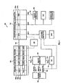
- FIG. 1 a block diagram depicting the steps of a method 100, performed in a networking device, of presenting different virtual router configuration to different end users, classes of service, or packets. Also shown are the data structures used in the performance of the method, and the logic elements that perform the method steps.
- the method is performed in the device after the packet has been parsed by packet parser 104, thus making available for use by the method certain packet fields successfully parsed by the parser 104, including VLAN 106, VMAN 108, and ingress port 110.
- the method may be performed in any networking device that is capable of forwarding or classifying packets at OSI layer three or above, including but not necessarily limited to routers, switches, or combination routers/switches.
- a “virtual router” includes both a “lightweight” virtual router, i.e ., one that virtually routes at OSI layer three, and a “heavyweight” virtual router, i.e ., one that virtually routes at OSI layer three, but in addition implements distinct OSI layer two functions per virtual router.
- the singular terms “device” or “router” include plural devices or routers, respectively.
- the VLAN field 106 designates a virtual LAN, a collection of network elements that may be physically disparate but are logically related such that they may be considered part of the same LAN for OSI layer two routing/switching purposes.
- the primary usage of the VLAN terminology is to uniquely identify logically related end user equipment within a VMAN (see below).
- the VMAN field 108 designates a virtual metropolitan network, a collection of network elements that may be physically disparate but are logically related such that they may be considered part of the same network.
- the term originally applied only to metropolitan networks that usage has evolved such that the term is now used to designate any network, metropolitan or non-metropolitan.
- the term is now primarily used by service providers to designate logically related infrastructure equipment.
- the VLAN terminology is now primarily used to uniquely identify logically related end user equipment within a VMAN.
- a VLAN value uniquely identifies a VLAN within a VMAN, the same VLAN value may not be used to refer to different end user equipment within a VMAN.
- the ingress port number 110 is an identifier of the physical port on which the packet was received at the device.
- the object of the method is to determine a virtual router identifier (VRID) 102 responsive to the incoming packet, wherein the virtual router identifier 102 identifies a particular virtual router configuration from a plurality of possible virtual router configurations.
- VRID virtual router identifier
- the method begins when key generation logic 112 forms a key from the VLAN 106, VMAN 108 and ingress port 110 fields.
- the key is formed by concatenating these three fields together, although it should be appreciated that other methods of forming the key are possible.
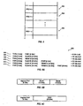
- an incoming packet received over ingress port X having a VLAN of Y, and a VMAN of Z, has a key 200 formatted as illustrated in Fig. 2a , with three concatenated fields, the first field 202 holding ingress port X, the second field 204 holding VLAN Y, and the third field 206 holding VMAN Z.
- the ingress port 110 is input to a lookup table 114 to determine a key type 116.
- the key type functions as a mask, by indicating which of the three fields of the key are to be wildcarded, i.e., ignored in the subsequent processing, and which are to be used.
- each of the three fields can be independently wild-carded or not.
- Fig. 2b illustrates a key type in which the ingress port and VMAN fields are wildcarded (designated by the X appearing in the corresponding fields), and only the VLAN field used in the subsequent processing.
- Fig. 2b illustrates a key type in which the ingress port and VMAN fields are wildcarded (designated by the X appearing in the corresponding fields), and only the VLAN field used in the subsequent processing.
- Fig. 2b illustrates a key type in which the ingress port and VMAN fields are wildcarded (designated by the X appearing in the corresponding fields), and only the VLAN field used in the subsequent processing.
- FIG. 2c illustrates a key type in which the ingress port field is wildcarded, and the VLAN and VMAN fields are used in the subsequent processing.
- Fig. 2d illustrates a key in which the VLAN field is wildcarded, and the ingress port and VMAN fields are used in the subsequent processing.
- Fig. 2e illustrates a key in which the VMAN field is wildcarded, and the ingress port and VLAN fields are used in the subsequent processing.
- the key type 116 is determined responsive to the ingress port field 110, which forms the input to lookup table 114.
- the table 114 has a plurality of entries each having an index value and a content value that specifies a particular key type, for example, such as illustrated in Figs. 2b-2e .
- a lookup occurs by mapping the ingress port field 110 into a particular index, looking up the entry having that index, and setting the key type to the content value of that entry.
- the key type may be determined responsive to other packet fields and more than one packet field.
- Fig. 6a illustrates an implementation where the key type is a 3 bit field, identified with numeral 602, that is appended to the key, and indicates both the format of the key and which fields of the key are to be wildcarded.
- the key type for key 604 indicates both that the key is 9 bits, and that the VLAN and VMAN fields are to be wildcarded
- the key type for key 606 indicates both that the key is 15 bits, and that the ingress port and VMAN fields are to be wildcarded
- the key type for key 608 indicates both that the key is 15 bits, and that the ingress port and VLAN fields are to be wildcarded
- the key type for key 610 indicates both that the key is 21 bits, and that the VMAN field is to be wildcarded
- the key type for key 612 indicates both that the key is 27 bits, and that the ingress port field is to be wildcarded
- the key type for key 614 indicates that the key is 33 bits, and that none of the fields are to be wildcarded.
- the key 118 is then mapped into the virtual router identifier 102 using a two-step indirection mapping process performed by logic 126.
- a table 120 is accessed, the table having a plurality of entries 120a, 120b, 120c, each having a content value and an index value, and locating an entry having a content value that matches the key.
- the content value of entry 120b is shown as matching the key 118.
- the index value of the matching entry forms an input to the second step of the process.
- the index value 122 of the matching entry 120b is mapped into the virtual router identifier 102 using an associated data store element 124.
- the associated data store element 124 has a plurality of entries 124a, 124b, each having an index value and a content value.
- the mapping is performed by selecting the entry in the associated data store element 124 whose index value matches the index value 122 for the matching entry in the table 120. In the particular example illustrated in Fig. 1 , entry 124b satisfies this condition.
- the content value of this entry is or contains the virtual router identifier 102.
- the table 120 is stored on a CAM, and the first step of the two-step process occurs by having the CAM search for and locate the entry 120b whose content value matches the key 118.
- the CAM is a binary CAM, i.e ., a CAM where each bit in the content value of an entry can only take on the binary values "0" and "1,”
- the previously described key type generation and masking processes should generally be performed as these functions are not available through the CAM.
- the CAM is a ternary CAM, i.e ., a CAM where each bit in the content value of an entry can take on the binary values "0" and "1,". but also a "don't care" value
- the previously described key type generation and masking processes are optional as these functions may be performed through suitable settings of the content values of the CAM entries.
- the table 120 is stored in RAM, and the first step of the two-step process occurs by applying a hash function to the key 118 to determine a table index for a starting entry, and then searching the table 120, beginning with the starting entry, to locate the entry 120b whose content value matches the key 118.
- Logic 128 configures the device in accordance with the VRID 102, and the configured device then forwards the packet.
- logic 128 selects or generates a CAM searching key responsive to the VRID 102.
- the CAM searching key is used in making a classification and forwarding decision for the packet.
- the logic 128 in effect selects the routing table that is used to route the packet.
- the foregoing embodiment overcomes the problems identified at the outset with the conventional approach for providing virtual router functionality.
- a key can be formed from a combination of a VLAN and VMAN field, and a VLAN is a unique identifier within a particular VMAN, the embodiment allows the VLAN to be used once again for virtual routing purposes.
- the embodiment dramatically increases the number of virtual routers that are possible.
- the number of virtual routers that can be presented is limited only by the size of the CAM. No longer does the size of the VLAN field limit the number of virtual routers than can be supported.
- the embodiment is flexible and easily accommodates changes in network usage or standards.
- a super-wide (24 bit) VLAN field i.e ., the ESID field
- the list of permissible Ethertypes That is handled simply by defining a new key type in the lookup table 114.
- the normal data type might have the format illustrated in Fig. 6b , i.e ., 12 bits for each of the VLAN, and VMAN fields, and 6 bits for the ingress port field
- the data type 116 might have the format illustrated in Fig.
- FIG. 6c i.e ., a 6 bit ingress port field followed by a 24 bit ESID field.
- logic 112 in Fig. 1 would format the key as indicated in this figure responsive to the fields 106, 108 and 110 from the packet parser, i.e ., it would assume the VLAN field 106 is a 24 bit ESID field.
- the embodiment is scaleable as an increase in the number of possible virtual routers would not necessarily require a commensurate increase in the number of routing tables that are maintained. Instead, many different key values could be mapped into the same VRID through appropriate settings of the index values associated with the entries 120a, 120b, 120c in the table 120. For example, in Fig. 1 , if it were desired that the index values for entries 120b and 120c map into the same VRID, the index values for the entries 120b and 120c would be set to the same value.
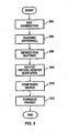
- Step 302 comprises the key generation step performed by the logic 112 in Fig. 1 .
- Step 304 comprises the optional key type generation and masking processes performed by the logic 112 in Fig. 1 , with the key type determined through an access to lookup table 112.
- the term "logic" refers to implementations in hardware, soflware, or combinations of hardware and soflware.
- Step 306 comprises the two-step indirection mapping process, wherein the first step involves searching or having performed a search through table 120, which may or may not be stored on a CAM, to find the entry 120b whose content value matches the key 118, and the second step involves locating the entry 124b in the associated data store 124, typically a RAM, whose index value matches the index value 122 of the matching entry in the table 120.
- Step 308 comprises outputting the virtual router identifier (VRID) 102. In Fig. 1 , this step involves outputting the content value, or a designated field in the content value, of the entry 124b whose index value matches the index value 122 of the matching entry in the table 120.
- VRID virtual router identifier
- Steps 306 and 308 are performed by logic 126 (illustrated in Fig. 1 ) through suitable accesses to table 120 and associated data element 124, as indicated by the dotted arrows between these elements.
- Step 310 comprises configuring the device to have the particular configuration identified by the virtual router identifier.
- this step is performed by logic 128 (illustrated in Fig. 1 ) when it selects or generates the CAM searching key that is used in making a classification and forwarding decision for the packet.
- the logic 128 in effect selects a routing table from a plurality of routing tables for use in routing the packet.
- the process is as illustrated in Fig. 5 , which shows selecting a routing table, for example, table 504, from a plurality of possible routing tables 502, 504, 506 responsive to the VRID, and preparing to forward the packet of interest using the selected routing table.
- step 312 comprises forwarding the packet in accordance with the configured device.
- this step is performed by a packet processor in the device.
- processor refers to any device capable of executing one or more commands, instructions or state transitions, and includes, without limitation, a general- or special-purpose microprocessor, finite state machine, controller, computer, digital signal processor (DSP), or the like.
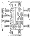
- FIG. 4 illustrates an embodiment 400 of a particular router architecture in which the aforementioned method may operate.
- the router is structured as a packet processing system comprising a packet classification/forwarding system 402 and a packet modification system 404.
- the packet classification/forwarding system 402 has an ingress portion 406 and an egress portion 408 through which ingress (network-side) packets may respectively enter and exit the packet classification/forwarding system 402.
- the packet modification system 404 has an ingress portion 410 and an egress portion 412 through which egress (switch-side) packets may respectively enter and exit the packet modification system 404.
- the ingress portion 406 of the packet classification/forwarding system 402 is coupled, through interface 418, to one or more network-side devices 414, and the egress portion 408 of the packet classification/forwarding system 402 is coupled, through interface 420, to one or more switch-side devices 416.
- the ingress portion 410 of the packet modification system 404 is coupled, through interface 422, to the one or more switch-side devices 416, and the egress portion 412 of the packet modification system 404 is coupled, through interface 423, to the one or more network-side devices 414.
- the packet classification system 402 further comprises a first packet parser 104 (the same packet parser 104 illustrated in Fig. 1 ), and a packet processor 428.
- Parser 104 is configured to parse an ingress packet and provide context pointers to the beginning of the packet layers, for example, pointers to the beginning of OSI layers 2, 3, and 4.
- Packet processor 428 is configured to classify and forward the packet, responsive to the context pointer provided by parser 104.
- CAM 442 is used by the packet classification/forwarding system 402 to perform packet searches to arrive at a classification/forwarding decision for a packet.
- the CAM 442 may be ternary, binary, or a combination of binary and ternary.
- the associated RAMs (ARAMs) 444a, 44b provide associated data for each entry in the CAM 442.
- the ARAMs 444a, 444b are accessed using the address (index value) returned by the CAM 442 as a result of a search operation.
- the ARAM 444a, 444b entry data is used to supply intermediate classification/forwarding information for the packet that is used by the packet processor 428 in making a final classification/forwarding decision for the packet.
- the table 120 which may or may not be stored on a CAM, and the associated data store 124, which collectively may be referred to as a Virtual Router Indirection Mapper (VRIM), are the same elements previously discussed in relation to Fig. 1 .
- VRIM Virtual Router Indirection Mapper
- the packet modification system 404 further comprises a second packet parser 430 for parsing an egress packet, modification processor 432, a fragment processor 436, a third packet parser 436, Access Control Logic (“ACL”) 438a, and L3/L4 checksum logic 438b.
- ACL Access Control Logic
- Parser 430 is configured to parse an egress packet and provide context pointers to the beginning of the packet layers, for example, pointers to the beginning of OSI layers 2, 3, and 4.
- Modification processor 432 modifies some or all of an egress packet responsive to the context pointers provided by parser 430, in the process disassembling the packet into fragments. Fragment processor 436 re-assembles the fragmented packet.
- the modification RAMs (“MRAMs”) 448a, 448b provides data and control structures for packet modification operations performed by the modification processors 432a, 432b.
- Parser 436 is configured to parse the reassembled packet and provide context pointers to the beginning of the packet layers, for example, pointers to the beginning of OSI layers 2, 3, and 4.
- ACL logic 438b arrives at an ACL decision with respect to a packet, such as CPU copy, mirror copy; and kill, responsive to the parsed packet layers provided by parser 436.
- the CPU copy action forwards a copy of the packet to a host 438 coupled to the system.
- the mirror copy action implements an egress mirroring function, in which a copy of the packet is forwarded to mirror FIFO 440 and then on to the egress portion 408 of the packet classification/forwarding system 402.
- the kill action either kills the packet or marks it for killing by a downstream Medium Access Control (MAC) processor.
- MAC Medium Access Control
- L3/L4 checksum logic 438b is configured to compute a checksum for a modified packet.
- logic 438b is configured to independently calculate a layer three (IP) and layer four (TCP/UDP) checksum.
- the interfaces 418, 420, 422, 424, and one or more of the CAM, VRIM, ARAM, or MRAM interfaces may be a QDR- or DDR-type interface as described in U.S. Patent Application Serial No. 10/655,742; filed September 4, 2003 , which is hereby fully incorporated by reference herein as though set forth in full.
- logic elements depicted in Fig. 1 are incorporated into the router of Fig. 4 within the forwarding and classification system 402, just downstream from the packet parser 104 and parallel with the packet processor 428.
- logic 112 in Fig. 1 performs the key generation step 302 of Fig. 3 responsive to parsed packet data provided by parser 104.
- Logic 112 also performs the optional key type generation and masking step 304 if a ternary CAM is not included in the VRIM 120, 124 and used as part of the indirection mapping process 306.
- a ternary CAM is included in the VRIM 120, 124, and used as part of the indirection mapping process 306, the key type generation and masking step 304 may be performed by this CAM.
- Logic 126 further performs the indirection mapping process 306 in conjunction with the elements of VRIM 120, 124, as well as the VRID outputting step 308.
- Packet processor 428 performs the configure device step 310 of Fig. 3 by using the VRID as the starting key to CAM 442, which determines the starting address of a sequence of commends executed by the packet processor 306 to make a classification and forwarding decision for an ingress packet.
- the packet processor 428 implicitly selects a routing table from a plurality of possible routing tables, as illustrated in Fig. 5 .
- Packet processor 428 also performs step 312 by classifying and forwarding the ingress packet responsive to the CAM searching process that is performed, at least initially, with the key determined responsive to the VRID 102.
Description
- This application relates generally to networking devices, and, specifically, to methods for configuring such devices so that they provide virtual router functionality, i.e., present different virtual router configurations to different end users, classes of service or packets.
- Virtual router functionality refers to the capability of the same physical networking device to present different virtual router configurations to different end users, classes of desired service, or packets. As a result of this capability, the same physical device appears as a plurality of different virtual routers. To implement this capability, current routers directly map a packet field of interest, typically the VLAN field, into the identifier of a particular routing table, and then use the particular routing table to route the packet. The VLAN field designates a virtual LAN, a collection of network elements that may be physically disparate but are logically related such that they may be considered part of the same LAN for OSI layer two routing/switching purposes. For example, all the network elements in a particular VLAN receive broadcasts from any other element in the VLAN at OSI layer two.
- This approach, whereby the VLAN of the incoming packet is directly mapped into-an identifier of a routing table, worked fine as long as different end users used non-overlapping VLANs, so that the VLAN could be used to present different virtual routers to different end users. However, as VLAN usage proliferated, different end users began using overlapping sets of VLANs, so the VLAN could no longer be used to present different virtual routers to different end users.
- Another problem is that the number of virtual routers that are possible is limited by the size of the VLAN field. A VLAN of 12 bits, for example, identifies only 4K different routing tables, which may not be sufficient for certain applications.
- A third problem is the lack of flexibility in this approach. If, for example, the VLAN type or format changes as network usage evolves or as network standards change, the approach would be rendered obsolete as it is tied to a particular VLAN type and format.
- A fourth problem is the lack of scalability of this approach with an increase in the number of virtual routers that may need to be accommodated. With this approach, for example, an increase in the size of the VLAN field to allow for an increase in virtual routers multiplies in direct proportion the number of routing tables that need to be maintained.
-
U.S. Patent Publication No. 2005/0074009 , entitled "Packet Transfer Unit," to Kanetake, et al. describes a packet transfer unit, which comprises a search key memory that stores a search key for a transfer destination of a packet and verification information generated from the search key, in association with a storage location of transfer information memorized in a transfer information memory. A transfer information acquisition unit searches the search key memory by using the search key generated based on the header information and the verification information generated from the search key, acquires storage location information of the transfer information from the search key memory when a match with the search key and the verification information memorized in the search key memory is found, and acquires the transfer information stored in the transfer information memory based on the acquired storage location information. A transfer unit transfers the packet based on the acquired transfer information. -
U.S. Patent Publication No. 2004/0246981 , entitled "System and Method of Accessing and Transmitting Different Data Frames in a Digital Transmission Network, to He, et al.," describes a method and system for accessing and transmitting different types of data frames in a digital transmission network. The system includes a data processing and dispatching device having at least an inter-device interface, a processing flow database, and a control interface unit. The method includes the steps of extracting type number information from data frames, searching for rules in the processing flow database corresponding to the extracted type number, determining the retrieved result and discarding the data frames if the retrieval result it blank. Otherwise an inter-device interface number is extracted and the data frames are output via the inter-device interface with the extracted inter-device interface number. - A further method and system for an aggregated VLAN network architecture is shown in
US 6,914,905 to Yip et al , in which several VLANs in a network share the same default router address and subnet mask, but remain isolated from one another's network traffic. - The invention provides a method of presenting different virtual routers to different end users, classes of service, or packets according to the features of
claim 1. The method may be performed in any networking device, and enables the device to provide virtual router functionality. The invention further applies to a system according to the features of claim 2. - The method begins when a packet is received having a VLAN field and at least one additional field. Upon receipt of the packet, a key is formed from the VLAN field and at least one additional packet field, for example, a VMAN field.
- The key is then mapped into a virtual router identifier (VRID) using an indirection mapping process. According to this indirect mapping process, a table having a plurality of entries, each having a content value and an index value, is accessed to locate an entry having a content value that matches the key. The index value of the matching entry is then mapped into the VRID using an associated data store element. The result is a virtual router identifier that identifies a particular virtual router configuration from a plurality of possible virtual router configurations.
- Other systems, methods, features and advantages of the invention will be or will become apparent to one with skill in the art upon examination of the following figures and detailed description. It is intended that all such additional systems, methods, features and advantages be included within this description, be within the scope of the invention, and be protected by the accompanying claims.
- The invention can be better understood with reference to the following figures. The components in the figures are not necessarily to scale, emphasis instead being placed upon illustrating the principles of the invention. Moreover, in the figures, like reference numerals designate corresponding parts throughout the different views.
-
Figure 1 is a block diagram showing the method steps, data structures and logic elements used in producing a virtual router identifier (VRID) according to one embodiment, characterized in that an indirect mapping process is used to map a key, generated from one or more packet fields, to the VRID. -
Figure 2a illustrates an example of a key format, andFigures 2b-2e illustrate various examples of key types wildcarding different ones of the fields making up the key format. -
Figure 3 is a flowchart illustrating the method steps in one embodiment, characterized in that the networking device is configured responsive to the VRID, and the packet then routed in accordance with the configured device. -
Figure 4 illustrates a particular switch architecture that embodies or utilizes the claimed method and system. -
Figure 5 illustrates a plurality of routing tables that may be used to support virtual router functionality. -
Figures 6a, 6b and 6c illustrate examples of alternative data types that may apply depending on the type of VLAN field detected in the ingress packet. - Referring to
Figure 1 , a block diagram depicting the steps of amethod 100, performed in a networking device, of presenting different virtual router configuration to different end users, classes of service, or packets. Also shown are the data structures used in the performance of the method, and the logic elements that perform the method steps. In this particular embodiment, the method is performed in the device after the packet has been parsed bypacket parser 104, thus making available for use by the method certain packet fields successfully parsed by theparser 104, including VLAN 106, VMAN 108, andingress port 110. The method may be performed in any networking device that is capable of forwarding or classifying packets at OSI layer three or above, including but not necessarily limited to routers, switches, or combination routers/switches. For purposes of this disclosure, a "virtual router" includes both a "lightweight" virtual router, i.e., one that virtually routes at OSI layer three, and a "heavyweight" virtual router, i.e., one that virtually routes at OSI layer three, but in addition implements distinct OSI layer two functions per virtual router. Additionally, for purposes of this disclosure, the singular terms "device" or "router" include plural devices or routers, respectively. - As previously explained, the
VLAN field 106 designates a virtual LAN, a collection of network elements that may be physically disparate but are logically related such that they may be considered part of the same LAN for OSI layer two routing/switching purposes. Presently, the primary usage of the VLAN terminology is to uniquely identify logically related end user equipment within a VMAN (see below). - The VMAN
field 108 designates a virtual metropolitan network, a collection of network elements that may be physically disparate but are logically related such that they may be considered part of the same network. Although the term originally applied only to metropolitan networks, that usage has evolved such that the term is now used to designate any network, metropolitan or non-metropolitan. In fact, as VMAN usage has proliferated, the term is now primarily used by service providers to designate logically related infrastructure equipment. At the same time, as explained above, the VLAN terminology is now primarily used to uniquely identify logically related end user equipment within a VMAN. Significantly, as a VLAN value uniquely identifies a VLAN within a VMAN, the same VLAN value may not be used to refer to different end user equipment within a VMAN. - The
ingress port number 110 is an identifier of the physical port on which the packet was received at the device. - Returning to
Figure 1 , the object of the method is to determine a virtual router identifier (VRID) 102 responsive to the incoming packet, wherein thevirtual router identifier 102 identifies a particular virtual router configuration from a plurality of possible virtual router configurations. - The method begins when
key generation logic 112 forms a key from theVLAN 106, VMAN 108 andingress port 110 fields. In the particular embodiment illustrated, the key is formed by concatenating these three fields together, although it should be appreciated that other methods of forming the key are possible. Thus, for example, in one embodiment, an incoming packet received over ingress port X, having a VLAN of Y, and a VMAN of Z, has a key 200 formatted as illustrated inFig. 2a , with three concatenated fields, thefirst field 202 holding ingress port X, thesecond field 204 holding VLAN Y, and thethird field 206 holding VMAN Z. - Concurrently, in one embodiment, the
ingress port 110 is input to a lookup table 114 to determine akey type 116. In this embodiment, the key type functions as a mask, by indicating which of the three fields of the key are to be wildcarded, i.e., ignored in the subsequent processing, and which are to be used. In this particular embodiment, each of the three fields can be independently wild-carded or not. Thus, for example,Fig. 2b illustrates a key type in which the ingress port and VMAN fields are wildcarded (designated by the X appearing in the corresponding fields), and only the VLAN field used in the subsequent processing. Similarly,Fig. 2c illustrates a key type in which the ingress port field is wildcarded, and the VLAN and VMAN fields are used in the subsequent processing.Fig. 2d illustrates a key in which the VLAN field is wildcarded, and the ingress port and VMAN fields are used in the subsequent processing.Fig. 2e illustrates a key in which the VMAN field is wildcarded, and the ingress port and VLAN fields are used in the subsequent processing. - In the embodiment illustrated in
Fig. 1 , thekey type 116 is determined responsive to theingress port field 110, which forms the input to lookup table 114. The table 114 has a plurality of entries each having an index value and a content value that specifies a particular key type, for example, such as illustrated inFigs. 2b-2e . A lookup occurs by mapping theingress port field 110 into a particular index, looking up the entry having that index, and setting the key type to the content value of that entry. In other embodiments, the key type may be determined responsive to other packet fields and more than one packet field. -
Fig. 6a illustrates an implementation where the key type is a 3 bit field, identified withnumeral 602, that is appended to the key, and indicates both the format of the key and which fields of the key are to be wildcarded. For example, the key type forkey 604 indicates both that the key is 9 bits, and that the VLAN and VMAN fields are to be wildcarded; the key type forkey 606 indicates both that the key is 15 bits, and that the ingress port and VMAN fields are to be wildcarded; the key type forkey 608 indicates both that the key is 15 bits, and that the ingress port and VLAN fields are to be wildcarded; the key type forkey 610 indicates both that the key is 21 bits, and that the VMAN field is to be wildcarded; the key type forkey 612 indicates both that the key is 27 bits, and that the ingress port field is to be wildcarded; and the key type forkey 614 indicates that the key is 33 bits, and that none of the fields are to be wildcarded. - Moreover, as will be discussed in greater detail below, in the case where a ternary CAM is used to perform the indirection mapping process, whereby the key is indirectly mapped into a virtual router identifier, just discussed key type generation and key masking processes are unnecessary as individual fields in the content values corresponding to the ternary CAM entries can be wildcarded, i.e., set as don't care values. In the case where a binary CAM is used to perform the indirection mapping process, the just discussed key type generation and key masking processes should generally be retained.
- Referring again to
Fig. 1 , the key 118, masked or unmasked as the case may be, is then mapped into thevirtual router identifier 102 using a two-step indirection mapping process performed bylogic 126. In the first step, as illustrated, a table 120 is accessed, the table having a plurality ofentries Fig. 1 , the content value ofentry 120b is shown as matching the key 118. The index value of the matching entry, identified withnumeral 122, forms an input to the second step of the process. - In the second step, the
index value 122 of thematching entry 120b is mapped into thevirtual router identifier 102 using an associateddata store element 124. The associateddata store element 124 has a plurality ofentries data store element 124 whose index value matches theindex value 122 for the matching entry in the table 120. In the particular example illustrated inFig. 1 ,entry 124b satisfies this condition. The content value of this entry is or contains thevirtual router identifier 102. - In one implementation, the table 120 is stored on a CAM, and the first step of the two-step process occurs by having the CAM search for and locate the
entry 120b whose content value matches the key 118. In the case where the CAM is a binary CAM, i.e., a CAM where each bit in the content value of an entry can only take on the binary values "0" and "1," the previously described key type generation and masking processes should generally be performed as these functions are not available through the CAM. However, in the case where the CAM is a ternary CAM, i.e., a CAM where each bit in the content value of an entry can take on the binary values "0" and "1,". but also a "don't care" value, the previously described key type generation and masking processes are optional as these functions may be performed through suitable settings of the content values of the CAM entries. - In a second implementation, the table 120 is stored in RAM, and the first step of the two-step process occurs by applying a hash function to the key 118 to determine a table index for a starting entry, and then searching the table 120, beginning with the starting entry, to locate the
entry 120b whose content value matches the key 118. -
Logic 128 configures the device in accordance with theVRID 102, and the configured device then forwards the packet. In one embodiment, as will be discussed in more detail later,logic 128 selects or generates a CAM searching key responsive to theVRID 102. The CAM searching key is used in making a classification and forwarding decision for the packet. By setting the key that is used throughout the classification and forwarding process responsive to theVRID 102, thelogic 128 in effect selects the routing table that is used to route the packet. - The foregoing embodiment overcomes the problems identified at the outset with the conventional approach for providing virtual router functionality. First, since a key can be formed from a combination of a VLAN and VMAN field, and a VLAN is a unique identifier within a particular VMAN, the embodiment allows the VLAN to be used once again for virtual routing purposes.
- Second, the embodiment dramatically increases the number of virtual routers that are possible. In the case, for example, where the table 120 is stored on a CAM, the number of virtual routers that can be presented is limited only by the size of the CAM. No longer does the size of the VLAN field limit the number of virtual routers than can be supported.
- Third, the embodiment is flexible and easily accommodates changes in network usage or standards. Consider, for example, the recent addition of a super-wide (24 bit) VLAN field, i.e., the ESID field, to the list of permissible Ethertypes. That is handled simply by defining a new key type in the lookup table 114. For example, while the normal data type might have the format illustrated in
Fig. 6b , i.e., 12 bits for each of the VLAN, and VMAN fields, and 6 bits for the ingress port field, when a super-wide VLAN (ESID) is detected, thedata type 116 might have the format illustrated inFig. 6c , i.e., a 6 bit ingress port field followed by a 24 bit ESID field. Upon encountering the key type ofFig. 6c ,logic 112 inFig. 1 would format the key as indicated in this figure responsive to thefields VLAN field 106 is a 24 bit ESID field. - Fourth, the embodiment is scaleable as an increase in the number of possible virtual routers would not necessarily require a commensurate increase in the number of routing tables that are maintained. Instead, many different key values could be mapped into the same VRID through appropriate settings of the index values associated with the
entries Fig. 1 , if it were desired that the index values forentries entries -
Fig. 3 summarizes the steps that are performed in one embodiment of the overall method. Step 302 comprises the key generation step performed by thelogic 112 inFig. 1 . Step 304 comprises the optional key type generation and masking processes performed by thelogic 112 inFig. 1 , with the key type determined through an access to lookup table 112. For purposes of this disclosure, the term "logic" refers to implementations in hardware, soflware, or combinations of hardware and soflware. - Step 306 comprises the two-step indirection mapping process, wherein the first step involves searching or having performed a search through table 120, which may or may not be stored on a CAM, to find the
entry 120b whose content value matches the key 118, and the second step involves locating theentry 124b in the associateddata store 124, typically a RAM, whose index value matches theindex value 122 of the matching entry in the table 120. Step 308 comprises outputting the virtual router identifier (VRID) 102. InFig. 1 , this step involves outputting the content value, or a designated field in the content value, of theentry 124b whose index value matches theindex value 122 of the matching entry in the table 120. -
Steps Fig. 1 ) through suitable accesses to table 120 and associateddata element 124, as indicated by the dotted arrows between these elements. - Step 310 comprises configuring the device to have the particular configuration identified by the virtual router identifier. In one embodiment, this step is performed by logic 128 (illustrated in
Fig. 1 ) when it selects or generates the CAM searching key that is used in making a classification and forwarding decision for the packet. By setting the key that is used throughput the classification and forwarding process, thelogic 128 in effect selects a routing table from a plurality of routing tables for use in routing the packet. Conceptually, the process is as illustrated inFig. 5 , which shows selecting a routing table, for example, table 504, from a plurality of possible routing tables 502, 504, 506 responsive to the VRID, and preparing to forward the packet of interest using the selected routing table. - Referring back to
Fig. 3 ,step 312 comprises forwarding the packet in accordance with the configured device. In one embodiment, this step is performed by a packet processor in the device. For purposes of this disclosure, the term "processor" refers to any device capable of executing one or more commands, instructions or state transitions, and includes, without limitation, a general- or special-purpose microprocessor, finite state machine, controller, computer, digital signal processor (DSP), or the like. -
Figure 4 illustrates anembodiment 400 of a particular router architecture in which the aforementioned method may operate. In this embodiment, as shown, the router is structured as a packet processing system comprising a packet classification/forwarding system 402 and apacket modification system 404. The packet classification/forwarding system 402 has aningress portion 406 and anegress portion 408 through which ingress (network-side) packets may respectively enter and exit the packet classification/forwarding system 402. Similarly, thepacket modification system 404 has aningress portion 410 and anegress portion 412 through which egress (switch-side) packets may respectively enter and exit thepacket modification system 404. - The
ingress portion 406 of the packet classification/forwarding system 402 is coupled, throughinterface 418, to one or more network-side devices 414, and theegress portion 408 of the packet classification/forwarding system 402 is coupled, throughinterface 420, to one or more switch-side devices 416. Similarly, theingress portion 410 of thepacket modification system 404 is coupled, throughinterface 422, to the one or more switch-side devices 416, and theegress portion 412 of thepacket modification system 404 is coupled, through interface 423, to the one or more network-side devices 414. - In addition to the ingress and
egress portions packet classification system 402 further comprises a first packet parser 104 (thesame packet parser 104 illustrated inFig. 1 ), and apacket processor 428. -
Parser 104 is configured to parse an ingress packet and provide context pointers to the beginning of the packet layers, for example, pointers to the beginning of OSI layers 2, 3, and 4. -
Packet processor 428 is configured to classify and forward the packet, responsive to the context pointer provided byparser 104. - Content Addressable Memory (CAM) 442 is used by the packet classification/
forwarding system 402 to perform packet searches to arrive at a classification/forwarding decision for a packet. TheCAM 442 may be ternary, binary, or a combination of binary and ternary. - The associated RAMs (ARAMs) 444a, 44b provide associated data for each entry in the
CAM 442. TheARAMs CAM 442 as a result of a search operation. TheARAM packet processor 428 in making a final classification/forwarding decision for the packet. - The table 120, which may or may not be stored on a CAM, and the associated
data store 124, which collectively may be referred to as a Virtual Router Indirection Mapper (VRIM), are the same elements previously discussed in relation toFig. 1 . - In addition to the ingress and
egress portions packet modification system 404 further comprises asecond packet parser 430 for parsing an egress packet,modification processor 432, afragment processor 436, athird packet parser 436, Access Control Logic ("ACL") 438a, and L3/L4 checksum logic 438b. -
Parser 430 is configured to parse an egress packet and provide context pointers to the beginning of the packet layers, for example, pointers to the beginning of OSI layers 2, 3, and 4. -
Modification processor 432 modifies some or all of an egress packet responsive to the context pointers provided byparser 430, in the process disassembling the packet into fragments.Fragment processor 436 re-assembles the fragmented packet. - The modification RAMs ("MRAMs") 448a, 448b provides data and control structures for packet modification operations performed by the modification processors 432a, 432b.
-
Parser 436 is configured to parse the reassembled packet and provide context pointers to the beginning of the packet layers, for example, pointers to the beginning of OSI layers 2, 3, and 4. -
ACL logic 438b arrives at an ACL decision with respect to a packet, such as CPU copy, mirror copy; and kill, responsive to the parsed packet layers provided byparser 436. The CPU copy action forwards a copy of the packet to ahost 438 coupled to the system. The mirror copy action implements an egress mirroring function, in which a copy of the packet is forwarded to mirrorFIFO 440 and then on to theegress portion 408 of the packet classification/forwarding system 402. The kill action either kills the packet or marks it for killing by a downstream Medium Access Control (MAC) processor. - L3/
L4 checksum logic 438b is configured to compute a checksum for a modified packet. In one embodiment,logic 438b is configured to independently calculate a layer three (IP) and layer four (TCP/UDP) checksum. - In one implementation, the
interfaces U.S. Patent Application Serial No. 10/655,742; filed September 4, 2003 - In one embodiment, the logic elements depicted in
Fig. 1 are incorporated into the router ofFig. 4 within the forwarding andclassification system 402, just downstream from thepacket parser 104 and parallel with thepacket processor 428. In this embodiment,logic 112 inFig. 1 performs thekey generation step 302 ofFig. 3 responsive to parsed packet data provided byparser 104.Logic 112 also performs the optional key type generation and maskingstep 304 if a ternary CAM is not included in theVRIM indirection mapping process 306. If a ternary CAM is included in theVRIM indirection mapping process 306, the key type generation and maskingstep 304 may be performed by this CAM.Logic 126 further performs theindirection mapping process 306 in conjunction with the elements ofVRIM VRID outputting step 308. -
Packet processor 428 performs the configuredevice step 310 ofFig. 3 by using the VRID as the starting key toCAM 442, which determines the starting address of a sequence of commends executed by thepacket processor 306 to make a classification and forwarding decision for an ingress packet. By using the VRID as the starting key to theCAM 442, thepacket processor 428 implicitly selects a routing table from a plurality of possible routing tables, as illustrated inFig. 5 . -
Packet processor 428 also performsstep 312 by classifying and forwarding the ingress packet responsive to the CAM searching process that is performed, at least initially, with the key determined responsive to theVRID 102. - While various embodiments of the invention have been described, it will be apparent to those of ordinary skill in the art that many more embodiments and implementations are possible that are within the scope of this invention. Accordingly, the invention is not to be restricted except in light of the attached claims and their equivalents.
Claims (19)
- A method, performed in, by or for a networking device, of presenting different virtual routers to different end users, classes of service, or packets comprising the steps of:receiving an incoming packet having a VLAN field (106) and an additional packet field (108,110);forming a key (118) by concatenating the VLAN field and the additional packet field of the incoming packet;mapping the key to a virtual router identifier (102) via a two-step indirection mapping process, comprising a first step and a second step, the virtual router identifier (102) identifying a particular virtual router configuration from amongst a plurality of possible virtual router configurations, each of which is characterized by a routing table, for routing packets at OSI layer three or higher, selected from a plurality of possible routing tables;wherein the first step of the two-step indirection mapping process comprising accessing a table (120) having a plurality of entries (120a, 120b, 120c), each having a content value and an index value (122), and locating a matching entry having a content value that matches the key;wherein the second step of the two-step indirection mapping process comprising mapping the index value of the matched entry from the first step of the two-step indirection mapping process into the virtual router identifier (102) by applying the index value to identify an entry in an associated data store element (124) that includes the virtual router identifier (102);mapping many different key values to the virtual router identifier (102) by appropriate settings of the index values (122) associated with the plurality of entries (120a, 120b, 120c) to increase a number of possible virtual routers presented to different end users, classes of service, or packets;configuring the networking device to have the particular configuration identified by the virtual router identifier (102) by selecting the routing table that characterizes the particular configuration identified by the virtual router identifier (102) for routing the packet at OSI layer three or higher; androuting the packet at OSI layer three or higher via the selected routing table that characterizes the particular configuration identified by the virtual router identifier.
- A system, in or associated with a networking device, of presenting different virtual routers to different end users, classes of service, or packets comprising:first logic unit (104) for receiving an incoming packet having a VLAN field (106) and an additional packet field (108, 110);second logic unit (112) forming a key (118) by concatenating the VLAN field and the additional packet field of the incoming packet;first means (126) for mapping the key into a virtual router identifier (102) via a two-step indirection mapping process, comprising a first step and a second step, the virtual router identifier identifying a particular virtual router configuration from amongst a plurality of possible virtual router configurations, each of which is characterized by a routing table, for use in routing packets at OSI layer three or higher, selected from a plurality of possible routing tables;wherein the first step of the two-step indirection mapping process comprising accessing a table (120) having a plurality of entries (120a, 120b, 120c), each having a content value and an index value (122), and locating a matching entry having a content value that matches the key;wherein the second step of the two-step indirection mapping process comprising mapping the index value of the matched entry from the first step of the two-step indirection mapping process into the virtual router identifier (102) by applying the index value to identify an entry in an associated data store element (124) that includes the virtual router identifier (102);means for mapping many different key values to the virtual router identifier (102) by appropriate settings of the index values (122) associated with the plurality of entries (120a, 120b, 120c) to increase a number of possible virtual routers presented to different end users, classes of service, or packets;second means (428) for configuring the networking device to have the particular configuration identified by the virtual router identifier by selecting the routing table that characterizes the particular configuration identified by the virtual router identifier for use in routing the packet at OSI layer three or higher; andthird means for routing the packet at OSI layer three or higher via the selected routing table that characterizes the particular configuration identified by the virtual router identifier.
- The method of claim 1 or system of claim 2 wherein the VLAN field is an ingress VLAN.
- The method of claim 1 or system of claim 2 wherein the VLAN field is an extended or super VLAN.
- The method of claim 1 or system of claim 2 wherein the key is a masked key.
- The method of claim 1 or system of claim 2 wherein the key is an unmasked key.
- The method or system of claim 5 wherein the key is masked using a key type (116) determined responsive to one or more packet fields.
- The method of claim 1 or system of claim 2 wherein the table is stored on a CAM, the first step of the two-step indirection mapping process comprises having the CAM search for and locate an entry whose content value matches the key, and the associated data store element comprises an associated RAM.
- The method of claim 1 or system of claim 2 wherein the table is stored in a RAM, the first step of the two-step indirection mapping process comprises applying a hash function to the key to determine a table index for a starting entry, and then searching the table beginning with the starting entry to locate an entry whose content value matches the key.
- The method of claim 1 or system of claim 2 wherein the CAM is a binary CAM.
- The method of claim 1 or system of claim 2 wherein the CAM is a ternary CAM.
- The method of claim 1 or system of claim 2 wherein the routing table characterizing the particular configuration identified by the virtual router identifier is implicitly selected by determining, responsive to the virtual router identifier, a starting address of a sequence of commands that are executed by a packet processor to route the packet.
- The method or system of claim 7 wherein the key type is determined by inputting an ingress port field (110) of the packet to a lookup table (114).
- The method of claim 1 or system of claim 2 wherein the additional packet field comprises a VMAN field (109).
- The method of claim 1 or system of claim 2 wherein the additional packet field comprises VMAN (109) and ingress port fields (110).
- The method of claim 1 or system of claim 2 wherein the additional packet field comprises an ingress port field (110).
- The method or system of claim 7 wherein the key is masked by wildcarding one or more fields of the packet based upon the key type.
- The method or system of claim 12 wherein the starting address is determined by performing a CAM access using the virtual router identifier as a key.
- The method or system of claim 11, further comprising wildcarding one or more fields of entries of the ternary CAM.
Priority Applications (1)
| Application Number | Priority Date | Filing Date | Title |
|---|---|---|---|
| EP11162449A EP2375647B1 (en) | 2005-12-30 | 2006-12-19 | Method of providing virtual router functionality |
Applications Claiming Priority (2)
| Application Number | Priority Date | Filing Date | Title |
|---|---|---|---|
| US11/324,159 US7894451B2 (en) | 2005-12-30 | 2005-12-30 | Method of providing virtual router functionality |
| PCT/US2006/049107 WO2007079035A1 (en) | 2005-12-30 | 2006-12-19 | Method of providing virtual router functionality |
Related Child Applications (1)
| Application Number | Title | Priority Date | Filing Date |
|---|---|---|---|
| EP11162449A Division-Into EP2375647B1 (en) | 2005-12-30 | 2006-12-19 | Method of providing virtual router functionality |
Publications (2)
| Publication Number | Publication Date |
|---|---|
| EP1969778A1 EP1969778A1 (en) | 2008-09-17 |
| EP1969778B1 true EP1969778B1 (en) | 2014-04-30 |
Family
ID=37983585
Family Applications (2)
| Application Number | Title | Priority Date | Filing Date |
|---|---|---|---|
| EP06846017.9A Active EP1969778B1 (en) | 2005-12-30 | 2006-12-19 | Method of providing virtual router functionality |
| EP11162449A Active EP2375647B1 (en) | 2005-12-30 | 2006-12-19 | Method of providing virtual router functionality |
Family Applications After (1)
| Application Number | Title | Priority Date | Filing Date |
|---|---|---|---|
| EP11162449A Active EP2375647B1 (en) | 2005-12-30 | 2006-12-19 | Method of providing virtual router functionality |
Country Status (5)
| Country | Link |
|---|---|
| US (1) | US7894451B2 (en) |
| EP (2) | EP1969778B1 (en) |
| JP (2) | JP5324225B2 (en) |
| CN (1) | CN101352003A (en) |
| WO (1) | WO2007079035A1 (en) |
Families Citing this family (29)
| Publication number | Priority date | Publication date | Assignee | Title |
|---|---|---|---|---|
| US7580350B1 (en) * | 2004-03-30 | 2009-08-25 | Extreme Networks, Inc. | System for deriving packet quality of service indicator |
| EP2228969B1 (en) * | 2005-06-09 | 2017-04-19 | Whirlpool Corporation | Software architecture system and method for communication with, and management of, at least one component within a household appliance |
| US8442042B2 (en) * | 2005-06-09 | 2013-05-14 | Whirlpool Corporation | Appliance and a consumable holder with an embedded virtual router |
| US7817633B1 (en) * | 2005-12-30 | 2010-10-19 | Extreme Networks, Inc. | Method of providing virtual router functionality through abstracted virtual identifiers |
| US7822033B1 (en) * | 2005-12-30 | 2010-10-26 | Extreme Networks, Inc. | MAC address detection device for virtual routers |
| US20080175241A1 (en) * | 2007-01-18 | 2008-07-24 | Ut Starcom, Incorporated | System and method for obtaining packet forwarding information |
| EP2294798B1 (en) * | 2008-03-31 | 2018-07-04 | Transpacific IP Group Limited | Method and related device for routing a data packet in a network |
| US8891358B2 (en) * | 2008-10-16 | 2014-11-18 | Hewlett-Packard Development Company, L.P. | Method for application broadcast forwarding for routers running redundancy protocols |
| CA3204215A1 (en) * | 2009-04-01 | 2010-10-07 | Nicira, Inc. | Method and apparatus for implementing and managing virtual switches |
| EP2466810B1 (en) * | 2010-12-17 | 2015-09-23 | Alcatel Lucent | Method and router for a service dependent routing |
| US9009217B1 (en) * | 2011-01-06 | 2015-04-14 | Amazon Technologies, Inc. | Interaction with a virtual network |
| US8605732B2 (en) | 2011-02-15 | 2013-12-10 | Extreme Networks, Inc. | Method of providing virtual router functionality |
| CN102137014B (en) * | 2011-03-11 | 2013-12-04 | 华为技术有限公司 | Resource management method, system and resource manager |
| US9154327B1 (en) | 2011-05-27 | 2015-10-06 | Cisco Technology, Inc. | User-configured on-demand virtual layer-2 network for infrastructure-as-a-service (IaaS) on a hybrid cloud network |
| JP5824911B2 (en) * | 2011-06-29 | 2015-12-02 | 富士通株式会社 | Information processing apparatus, information processing program, and management method |
| JP5625217B2 (en) * | 2011-07-04 | 2014-11-19 | アラクサラネットワークス株式会社 | Network management system and management computer |
| JP5831035B2 (en) * | 2011-08-18 | 2015-12-09 | 富士通株式会社 | Interface module, communication device, and communication method |
| CN103139067B (en) * | 2011-11-28 | 2015-08-05 | 百度在线网络技术(北京)有限公司 | Based on the mthods, systems and devices of VRRP protocol extension virtual router quantity |
| US8660129B1 (en) | 2012-02-02 | 2014-02-25 | Cisco Technology, Inc. | Fully distributed routing over a user-configured on-demand virtual network for infrastructure-as-a-service (IaaS) on hybrid cloud networks |
| CA2867577C (en) * | 2012-03-20 | 2019-07-02 | Raytheon Company | Routing a data packet in a communication network |
| CN102946358B (en) * | 2012-11-23 | 2015-07-15 | 武汉虹信通信技术有限责任公司 | Quick message three-layer transmitting method for automatic control (AC) device in wireless local area network (WLAN) network |
| DE102014207479A1 (en) * | 2014-04-17 | 2015-10-22 | Robert Bosch Gmbh | Method for classifying a data segment with regard to its further processing |
| US9537789B2 (en) | 2014-10-31 | 2017-01-03 | Raytheon Company | Resource allocating in a network |
| CN106612211B (en) * | 2015-10-23 | 2020-02-21 | 华为技术有限公司 | Path detection method, controller and network equipment in VxLAN |
| US10630576B2 (en) * | 2016-08-05 | 2020-04-21 | Huawei Technologies Co., Ltd. | Virtual network routing to dynamic end point locations in support of service-based traffic forwarding |
| CN110651451B (en) * | 2017-05-24 | 2021-03-02 | 瑞典爱立信有限公司 | Routing table selection method and network equipment in routing system based on strategy |
| CN109446831A (en) * | 2018-12-26 | 2019-03-08 | 贵州华芯通半导体技术有限公司 | Key generation and verification method and system based on hardware device |
| US11095735B2 (en) | 2019-08-06 | 2021-08-17 | Tealium Inc. | Configuration of event data communication in computer networks |
| US11146656B2 (en) | 2019-12-20 | 2021-10-12 | Tealium Inc. | Feature activation control and data prefetching with network-connected mobile devices |
Citations (2)
| Publication number | Priority date | Publication date | Assignee | Title |
|---|---|---|---|---|
| US20050074009A1 (en) * | 2003-10-03 | 2005-04-07 | Tatsuo Kanetake | Packet transfer unit |
| EP1601137A1 (en) * | 2003-02-19 | 2005-11-30 | NEC Corporation | Network system, learning bridge node, learning method, and program thereof |
Family Cites Families (113)
| Publication number | Priority date | Publication date | Assignee | Title |
|---|---|---|---|---|
| US5072443A (en) * | 1989-07-28 | 1991-12-10 | At&T Bell Laboratories | Communications system |
| US5282270A (en) * | 1990-06-06 | 1994-01-25 | Apple Computer, Inc. | Network device location using multicast |
| US5431676A (en) * | 1993-03-05 | 1995-07-11 | Innerdyne Medical, Inc. | Trocar system having expandable port |
| US5473599A (en) * | 1994-04-22 | 1995-12-05 | Cisco Systems, Incorporated | Standby router protocol |
| US5559975A (en) * | 1994-06-01 | 1996-09-24 | Advanced Micro Devices, Inc. | Program counter update mechanism |
| IL116989A (en) * | 1996-01-31 | 1999-10-28 | Galileo Technology Ltd | Switching ethernet controller |
| US5764636A (en) * | 1996-03-28 | 1998-06-09 | Cisco Technology, Inc. | Color blocking logic mechanism for a high-performance network switch |
| US6275861B1 (en) * | 1996-09-27 | 2001-08-14 | Pmc-Sierra, Inc. | Method and apparatus to identify flows in data systems |
| US5999518A (en) * | 1996-12-04 | 1999-12-07 | Alcatel Usa Sourcing, L.P. | Distributed telecommunications switching system and method |
| US6098109A (en) * | 1996-12-30 | 2000-08-01 | Compaq Computer Corporation | Programmable arbitration system for determining priority of the ports of a network switch |
| US5852607A (en) * | 1997-02-26 | 1998-12-22 | Cisco Technology, Inc. | Addressing mechanism for multiple look-up tables |
| US6173333B1 (en) * | 1997-07-18 | 2001-01-09 | Interprophet Corporation | TCP/IP network accelerator system and method which identifies classes of packet traffic for predictable protocols |
| US6295299B1 (en) * | 1997-08-29 | 2001-09-25 | Extreme Networks, Inc. | Data path architecture for a LAN switch |
| US6553002B1 (en) * | 1997-08-29 | 2003-04-22 | Ascend Communications, Inc. | Apparatus and method for routing data packets through a communications network |
| US6034957A (en) * | 1997-08-29 | 2000-03-07 | Extreme Networks, Inc. | Sliced comparison engine architecture and method for a LAN switch |
| US6172980B1 (en) * | 1997-09-11 | 2001-01-09 | 3Com Corporation | Multiple protocol support |
| US6199140B1 (en) * | 1997-10-30 | 2001-03-06 | Netlogic Microsystems, Inc. | Multiport content addressable memory device and timing signals |
| US6208649B1 (en) * | 1998-03-11 | 2001-03-27 | Cisco Technology, Inc. | Derived VLAN mapping technique |
| US6658002B1 (en) * | 1998-06-30 | 2003-12-02 | Cisco Technology, Inc. | Logical operation unit for packet processing |
| IL125272A0 (en) | 1998-07-08 | 1999-03-12 | Galileo Technology Ltd | Vlan protocol |
| US6256314B1 (en) * | 1998-08-11 | 2001-07-03 | Avaya Technology Corp. | Apparatus and methods for routerless layer 3 forwarding in a network |
| US6266705B1 (en) * | 1998-09-29 | 2001-07-24 | Cisco Systems, Inc. | Look up mechanism and associated hash table for a network switch |
| US6917617B2 (en) * | 1998-12-16 | 2005-07-12 | Cisco Technology, Inc. | Use of precedence bits for quality of service |
| US6515963B1 (en) * | 1999-01-27 | 2003-02-04 | Cisco Technology, Inc. | Per-flow dynamic buffer management |
| CN100477623C (en) * | 1999-02-23 | 2009-04-08 | 阿尔卡塔尔互联网运行公司 | Multibusiness network exchanger having modulator demodulator management |
| US6574702B2 (en) * | 1999-02-23 | 2003-06-03 | Netlogic Microsystems, Inc. | Method and apparatus for determining an exact match in a content addressable memory device |
| US6397260B1 (en) * | 1999-03-08 | 2002-05-28 | 3Com Corporation | Automatic load sharing for network routers |
| US6570877B1 (en) * | 1999-04-07 | 2003-05-27 | Cisco Technology, Inc. | Search engine for forwarding table content addressable memory |
| US6888797B1 (en) * | 1999-05-05 | 2005-05-03 | Lucent Technologies Inc. | Hashing-based network load balancing |
| US6768992B1 (en) * | 1999-05-17 | 2004-07-27 | Lynne G. Jolitz | Term addressable memory of an accelerator system and method |
| US6362990B1 (en) * | 1999-09-10 | 2002-03-26 | Sibercore Technologies | Three port content addressable memory device and methods for implementing the same |
| US6775281B1 (en) | 1999-09-30 | 2004-08-10 | Mosaid Technologies, Inc. | Method and apparatus for a four-way hash table |
| US6882642B1 (en) * | 1999-10-14 | 2005-04-19 | Nokia, Inc. | Method and apparatus for input rate regulation associated with a packet processing pipeline |
| US6738892B1 (en) * | 1999-10-20 | 2004-05-18 | Transmeta Corporation | Use of enable bits to control execution of selected instructions |
| US6463067B1 (en) * | 1999-12-13 | 2002-10-08 | Ascend Communications, Inc. | Submission and response architecture for route lookup and packet classification requests |
| US6661791B1 (en) * | 1999-12-28 | 2003-12-09 | Mosaid Technologies, Inc. | Method and apparatus for generating forward overrides in a packet switch |
| GB2358760B (en) * | 2000-01-25 | 2003-06-25 | 3Com Corp | Network switch with self-learning routing facility |
| US6977930B1 (en) | 2000-02-14 | 2005-12-20 | Cisco Technology, Inc. | Pipelined packet switching and queuing architecture |
| JP2001237881A (en) * | 2000-02-23 | 2001-08-31 | Nec Corp | Table type data retrieval device and packet processing system using it, and table type data retrieval method |
| US6384750B1 (en) * | 2000-03-23 | 2002-05-07 | Mosaid Technologies, Inc. | Multi-stage lookup for translating between signals of different bit lengths |
| JP3591420B2 (en) * | 2000-04-07 | 2004-11-17 | 日本電気株式会社 | Cache table management device and program recording medium in router |
| US6735670B1 (en) * | 2000-05-12 | 2004-05-11 | 3Com Corporation | Forwarding table incorporating hash table and content addressable memory |
| US20010048661A1 (en) * | 2000-05-24 | 2001-12-06 | David Clear | Method and apparatus for multi-protocol redundant router protocol support |
| JP4099930B2 (en) * | 2000-06-02 | 2008-06-11 | 株式会社日立製作所 | Router device and VPN identification information setting method |
| US6914905B1 (en) * | 2000-06-16 | 2005-07-05 | Extreme Networks, Inc. | Method and system for VLAN aggregation |
| US6631465B1 (en) * | 2000-06-30 | 2003-10-07 | Intel Corporation | Method and apparatus for instruction re-alignment using a branch on a falsehood of a qualifying predicate |
| US6381242B1 (en) * | 2000-08-29 | 2002-04-30 | Netrake Corporation | Content processor |
| US6678840B1 (en) | 2000-08-31 | 2004-01-13 | Hewlett-Packard Development Company, Lp. | Fault containment and error recovery in a scalable multiprocessor |
| US6792502B1 (en) * | 2000-10-12 | 2004-09-14 | Freescale Semiconductor, Inc. | Microprocessor having a content addressable memory (CAM) device as a functional unit therein and method of operation |
| US6765881B1 (en) * | 2000-12-06 | 2004-07-20 | Covad Communications Group, Inc. | Virtual L2TP/VPN tunnel network and spanning tree-based method for discovery of L2TP/VPN tunnels and other layer-2 services |
| JP3601445B2 (en) * | 2000-12-06 | 2004-12-15 | 日本電気株式会社 | Packet transfer apparatus, transfer information management method used therefor, and transfer information search method thereof |
| US7062641B1 (en) * | 2001-01-10 | 2006-06-13 | Cisco Technology, Inc. | Method and apparatus for unified exception handling with distributed exception identification |
| WO2002061599A1 (en) * | 2001-01-25 | 2002-08-08 | Crescent Networks, Inc. | Extension of address resolution protocol (arp) for internet protocol (ip) virtual networks |
| US7342942B1 (en) * | 2001-02-07 | 2008-03-11 | Cortina Systems, Inc. | Multi-service segmentation and reassembly device that maintains only one reassembly context per active output port |
| US6940856B2 (en) * | 2001-03-05 | 2005-09-06 | International Business Machines Corporation | Multicast buffered switch and method for operating a multicast buffered switch |
| US7193997B2 (en) * | 2001-03-19 | 2007-03-20 | International Business Machines Corporation | Packet classification |
| US6381162B1 (en) * | 2001-03-19 | 2002-04-30 | Tality, L.P. | Circuitry and method for controlling current surge on rails of parallel-pulldown-match-detect-type content addressable memory arrays |
| US6957258B2 (en) * | 2001-03-28 | 2005-10-18 | Netrake Corporation | Policy gateway |
| US7099912B2 (en) * | 2001-04-24 | 2006-08-29 | Hitachi, Ltd. | Integrated service management system |
| JP2002325090A (en) * | 2001-04-26 | 2002-11-08 | Nec Corp | Virtual router |
| US20030005210A1 (en) * | 2001-05-24 | 2003-01-02 | Thummalapally Damodar Reddy | Intelligent CAM cell for CIDR processor |
| JP3956685B2 (en) * | 2001-05-31 | 2007-08-08 | 古河電気工業株式会社 | Network connection method, virtual network connection device, and network connection system using the device |
| US6976158B2 (en) | 2001-06-01 | 2005-12-13 | Microchip Technology Incorporated | Repeat instruction with interrupt |
| US7092354B2 (en) * | 2001-06-07 | 2006-08-15 | Intel Corporation | Method and apparatus to provide redundancy in a network |
| US6999462B1 (en) * | 2001-06-18 | 2006-02-14 | Advanced Micro Devices, Inc. | Mapping layer 2 LAN priorities to a virtual lane in an Infiniband™ network |
| US6928478B1 (en) * | 2001-06-25 | 2005-08-09 | Network Appliance, Inc. | Method and apparatus for implementing a MAC address pool for assignment to a virtual interface aggregate |
| US7363353B2 (en) * | 2001-07-06 | 2008-04-22 | Juniper Networks, Inc. | Content service aggregation device for a data center |
| US7248585B2 (en) * | 2001-10-22 | 2007-07-24 | Sun Microsystems, Inc. | Method and apparatus for a packet classifier |
| US6892309B2 (en) * | 2002-02-08 | 2005-05-10 | Enterasys Networks, Inc. | Controlling usage of network resources by a user at the user's entry point to a communications network based on an identity of the user |
| US6871262B1 (en) * | 2002-02-14 | 2005-03-22 | Cisco Technology, Inc. | Method and apparatus for matching a string with multiple lookups using a single associative memory |
| JP2003244185A (en) * | 2002-02-18 | 2003-08-29 | Matsushita Electric Ind Co Ltd | Vlan and vlan frame switching apparatus |
| US7359387B2 (en) * | 2002-03-01 | 2008-04-15 | Verizon Business Global Llc | Systems and methods for implementing virtual router |
| US7190696B1 (en) * | 2002-03-05 | 2007-03-13 | Force10 Networks, Inc. | System and method for distributing packets among a plurality of paths to a destination |
| US6751110B2 (en) * | 2002-03-08 | 2004-06-15 | Micron Technology, Inc. | Static content addressable memory cell |
| US6842791B2 (en) | 2002-03-20 | 2005-01-11 | Intel Corporation | Method and apparatus for memory efficient fast VLAN lookups and inserts in hardware-based packet switches |
| JP2003308206A (en) * | 2002-04-15 | 2003-10-31 | Fujitsu Ltd | Processor device |
| US7212837B1 (en) * | 2002-05-24 | 2007-05-01 | Airespace, Inc. | Method and system for hierarchical processing of protocol information in a wireless LAN |
| US7218647B2 (en) * | 2002-06-27 | 2007-05-15 | International Business Machines Corporation | Method and apparatus for implementing frame header alterations |
| US7493480B2 (en) * | 2002-07-18 | 2009-02-17 | International Business Machines Corporation | Method and apparatus for prefetching branch history information |
| US7248584B2 (en) * | 2002-08-07 | 2007-07-24 | Intel Corporation | Network packet processing |
| US20040205753A1 (en) * | 2002-08-16 | 2004-10-14 | Globespan Virata Inc. | Timing ring mechanism |
| US7079407B1 (en) * | 2002-10-18 | 2006-07-18 | Netlogic Microsystems, Inc. | Content addressable memory (CAM) device including match line sensing |
| US7154902B1 (en) * | 2002-10-21 | 2006-12-26 | Force10 Networks, Inc. | Epoch-based packet switching |
| JP4241329B2 (en) * | 2002-11-20 | 2009-03-18 | 株式会社日立コミュニケーションテクノロジー | Virtual access router |
| JP2004172917A (en) * | 2002-11-20 | 2004-06-17 | Nec Corp | Packet retrieving device, packet process retrieving method, and program |
| JP4028793B2 (en) * | 2002-12-03 | 2007-12-26 | 株式会社日立製作所 | Mobile terminal apparatus and inter-terminal packet communication method |
| US7237172B2 (en) * | 2002-12-24 | 2007-06-26 | Micron Technology, Inc. | Error detection and correction in a CAM |
| US6996501B1 (en) * | 2002-12-24 | 2006-02-07 | Western Digital Technologies, Inc. | Disk drive executing a manufacturing program internally by executing disk commands through a vector |
| EP1588530A2 (en) | 2003-01-27 | 2005-10-26 | Raza Microelectronics, Inc. | Method and device for the classification and redirection of data packets in a heterogeneous network |
| JP3823089B2 (en) * | 2003-01-27 | 2006-09-20 | インターナショナル・ビジネス・マシーンズ・コーポレーション | Fixed-length data search device, fixed-length data search method, computer program, and computer-readable recording medium |
| CN100440825C (en) * | 2003-01-28 | 2008-12-03 | 华为技术有限公司 | System and method for switchingin and transmission of different data frames in digital transmission network |
| US20040208197A1 (en) * | 2003-04-15 | 2004-10-21 | Swaminathan Viswanathan | Method and apparatus for network protocol bridging |
| US7111101B1 (en) * | 2003-05-07 | 2006-09-19 | Ayago Technologies General Ip (Singapore) Ptd. Ltd. | Method and system for port numbering in an interconnect device |
| US7299227B2 (en) * | 2003-09-09 | 2007-11-20 | Stmicroelectronics, Inc. | Method and system for providing cascaded trie-based network packet search engines |
| US7296100B1 (en) * | 2003-10-06 | 2007-11-13 | Redpine Signals, Inc. | Packet buffer management apparatus and method |
| US20050198362A1 (en) * | 2003-12-31 | 2005-09-08 | Navada Muraleedhara H. | Exception packet forwarding |
| GB0400974D0 (en) * | 2004-01-16 | 2004-02-18 | Solexa Ltd | Multiple inexact matching |
| KR100733020B1 (en) * | 2004-01-16 | 2007-06-29 | 니폰덴신뎅와 가부시키가이샤 | Customer MAC Frame Forwarding Method, Edge Bridge, And Storage Medium Registering Program |
| US7403474B2 (en) * | 2004-01-27 | 2008-07-22 | Hewlett-Packard Development Company, L.P. | Redundant router set up |
| US7487938B2 (en) * | 2004-02-17 | 2009-02-10 | Thales Avionics, Inc. | System and method utilizing Internet Protocol (IP) sequencing to identify components of a passenger flight information system (PFIS) |
| US7649879B2 (en) * | 2004-03-30 | 2010-01-19 | Extreme Networks, Inc. | Pipelined packet processor |
| US7304996B1 (en) | 2004-03-30 | 2007-12-04 | Extreme Networks, Inc. | System and method for assembling a data packet |
| US9491084B2 (en) | 2004-06-17 | 2016-11-08 | Hewlett Packard Enterprise Development Lp | Monitoring path connectivity between teamed network resources of a computer system and a core network |
| JP2006025121A (en) * | 2004-07-07 | 2006-01-26 | Fujitsu Ltd | Frame transfer method and device therefor |
| US7515589B2 (en) * | 2004-08-27 | 2009-04-07 | International Business Machines Corporation | Method and apparatus for providing network virtualization |
| JP2006086800A (en) * | 2004-09-16 | 2006-03-30 | Fujitsu Ltd | Communication apparatus for selecting source address |
| CN100583818C (en) * | 2004-09-16 | 2010-01-20 | 日本电气株式会社 | Method for switching network connecting device in network system and network system |
| US20060092950A1 (en) * | 2004-10-28 | 2006-05-04 | Cisco Technology, Inc. | Architecture and method having redundancy in active/active stateful devices based on symmetric global load balancing protocol (sGLBP) |
| US7461154B2 (en) * | 2004-11-18 | 2008-12-02 | Cisco Technology, Inc. | Communication arrangement between virtual routers of a physical router |
| US7561531B2 (en) * | 2005-04-19 | 2009-07-14 | Intel Corporation | Apparatus and method having a virtual bridge to route data frames |
| US20070291791A1 (en) * | 2006-06-16 | 2007-12-20 | The Boeing Company. | Dynamic reconfigurable embedded compression common operating environment |
| JP2008079175A (en) * | 2006-09-25 | 2008-04-03 | Alaxala Networks Corp | Frame transfer system |
| US8259720B2 (en) * | 2007-02-02 | 2012-09-04 | Cisco Technology, Inc. | Triple-tier anycast addressing |
-
2005
- 2005-12-30 US US11/324,159 patent/US7894451B2/en active Active
-
2006
- 2006-12-19 CN CNA2006800501649A patent/CN101352003A/en active Pending
- 2006-12-19 WO PCT/US2006/049107 patent/WO2007079035A1/en active Application Filing
- 2006-12-19 JP JP2008548656A patent/JP5324225B2/en not_active Expired - Fee Related
- 2006-12-19 EP EP06846017.9A patent/EP1969778B1/en active Active
- 2006-12-19 EP EP11162449A patent/EP2375647B1/en active Active
-
2012
- 2012-11-06 JP JP2012244305A patent/JP5567641B2/en not_active Expired - Fee Related
Patent Citations (2)
| Publication number | Priority date | Publication date | Assignee | Title |
|---|---|---|---|---|
| EP1601137A1 (en) * | 2003-02-19 | 2005-11-30 | NEC Corporation | Network system, learning bridge node, learning method, and program thereof |
| US20050074009A1 (en) * | 2003-10-03 | 2005-04-07 | Tatsuo Kanetake | Packet transfer unit |
Also Published As
| Publication number | Publication date |
|---|---|
| EP2375647A1 (en) | 2011-10-12 |
| JP2013051729A (en) | 2013-03-14 |
| JP2009522868A (en) | 2009-06-11 |
| US7894451B2 (en) | 2011-02-22 |
| US20070153808A1 (en) | 2007-07-05 |
| EP1969778A1 (en) | 2008-09-17 |
| CN101352003A (en) | 2009-01-21 |
| WO2007079035A1 (en) | 2007-07-12 |
| JP5567641B2 (en) | 2014-08-06 |
| EP2375647B1 (en) | 2012-11-28 |
| JP5324225B2 (en) | 2013-10-23 |
Similar Documents
| Publication | Publication Date | Title |
|---|---|---|
| EP1969778B1 (en) | Method of providing virtual router functionality | |
| US6172980B1 (en) | Multiple protocol support | |
| US6950434B1 (en) | Arrangement for searching packet policies using multi-key hash searches in a network switch | |
| EP1670187B1 (en) | Tagging rules for hybrid ports | |
| US6674769B1 (en) | Simultaneous searching of layer 3 policy filter and policy cache in a network switch port | |
| US7079537B1 (en) | Layer 3 switching logic architecture in an integrated network switch | |
| JP4606678B2 (en) | Method and apparatus for wire-speed IP multicast forwarding | |
| US6798788B1 (en) | Arrangement determining policies for layer 3 frame fragments in a network switch | |
| US8259726B2 (en) | Method and apparatus for forwarding table reduction | |
| EP1158725B1 (en) | Method and apparatus for multi- redundant router protocol support | |
| JP4685254B2 (en) | Priority remapping for data communication switches | |
| US20050171937A1 (en) | Memory efficient hashing algorithm | |
| WO2018178906A1 (en) | Flexible processor of a port extender device | |
| US20030223364A1 (en) | Classifying and distributing traffic at a network node | |
| US7346059B1 (en) | Header range check hash circuit | |
| JP2002314571A (en) | Classification and tagging rules for switching nodes | |
| JP2000156713A (en) | Transfer/filtering method of content base in network- switching device | |
| EP3292659B1 (en) | Multicast data packet forwarding | |
| US20190372896A1 (en) | Longest Prefix Matching Providing Packet Processing and/or Memory Efficiencies in Processing of Packets | |
| WO2016128833A1 (en) | Method and system for identifying an incoming interface using openflow protocol | |
| KR20090054316A (en) | Ingress node and egress node improved packet transmission rate on the mpls network, and improving method for packet transmission rate on the mpls network system | |
| US8605732B2 (en) | Method of providing virtual router functionality | |
| US7103035B1 (en) | Arrangement for searching network addresses in a network switch using multiple tables based on subnet identifier | |
| US20070124495A1 (en) | Methods and systems for policy based routing | |
| US7817633B1 (en) | Method of providing virtual router functionality through abstracted virtual identifiers |
Legal Events
| Date | Code | Title | Description |
|---|---|---|---|
| PUAI | Public reference made under article 153(3) epc to a published international application that has entered the european phase |
Free format text: ORIGINAL CODE: 0009012 |
|
| 17P | Request for examination filed |
Effective date: 20080716 |
|
| AK | Designated contracting states |
Kind code of ref document: A1 Designated state(s): AT BE BG CH CY CZ DE DK EE ES FI FR GB GR HU IE IS IT LI LT LU LV MC NL PL PT RO SE SI SK TR |
|
| 17Q | First examination report despatched |
Effective date: 20090416 |
|
| DAX | Request for extension of the european patent (deleted) | ||
| REG | Reference to a national code |
Ref country code: DE Ref legal event code: R079 Ref document number: 602006041368 Country of ref document: DE Free format text: PREVIOUS MAIN CLASS: H04L0012460000 Ipc: H04L0012931000 |
|
| GRAP | Despatch of communication of intention to grant a patent |
Free format text: ORIGINAL CODE: EPIDOSNIGR1 |
|
| RIC1 | Information provided on ipc code assigned before grant |
Ipc: H04L 12/947 20130101ALI20131008BHEP Ipc: H04L 12/46 20060101ALI20131008BHEP Ipc: H04L 12/701 20130101ALI20131008BHEP Ipc: H04L 12/931 20130101AFI20131008BHEP |
|
| INTG | Intention to grant announced |
Effective date: 20131114 |
|
| GRAS | Grant fee paid |
Free format text: ORIGINAL CODE: EPIDOSNIGR3 |
|
| GRAA | (expected) grant |
Free format text: ORIGINAL CODE: 0009210 |
|
| AK | Designated contracting states |
Kind code of ref document: B1 Designated state(s): AT BE BG CH CY CZ DE DK EE ES FI FR GB GR HU IE IS IT LI LT LU LV MC NL PL PT RO SE SI SK TR |
|
| REG | Reference to a national code |
Ref country code: GB Ref legal event code: FG4D Ref country code: CH Ref legal event code: EP |
|
| REG | Reference to a national code |
Ref country code: AT Ref legal event code: REF Ref document number: 665742 Country of ref document: AT Kind code of ref document: T Effective date: 20140515 |
|
| REG | Reference to a national code |
Ref country code: IE Ref legal event code: FG4D |
|
| REG | Reference to a national code |
Ref country code: DE Ref legal event code: R096 Ref document number: 602006041368 Country of ref document: DE Effective date: 20140612 |
|
| REG | Reference to a national code |
Ref country code: AT Ref legal event code: MK05 Ref document number: 665742 Country of ref document: AT Kind code of ref document: T Effective date: 20140430 |
|
| REG | Reference to a national code |
Ref country code: LT Ref legal event code: MG4D |
|
| REG | Reference to a national code |
Ref country code: NL Ref legal event code: VDEP Effective date: 20140430 |
|
| PG25 | Lapsed in a contracting state [announced via postgrant information from national office to epo] |
Ref country code: CY Free format text: LAPSE BECAUSE OF FAILURE TO SUBMIT A TRANSLATION OF THE DESCRIPTION OR TO PAY THE FEE WITHIN THE PRESCRIBED TIME-LIMIT Effective date: 20140430 Ref country code: NL Free format text: LAPSE BECAUSE OF FAILURE TO SUBMIT A TRANSLATION OF THE DESCRIPTION OR TO PAY THE FEE WITHIN THE PRESCRIBED TIME-LIMIT Effective date: 20140430 Ref country code: IS Free format text: LAPSE BECAUSE OF FAILURE TO SUBMIT A TRANSLATION OF THE DESCRIPTION OR TO PAY THE FEE WITHIN THE PRESCRIBED TIME-LIMIT Effective date: 20140830 Ref country code: BG Free format text: LAPSE BECAUSE OF FAILURE TO SUBMIT A TRANSLATION OF THE DESCRIPTION OR TO PAY THE FEE WITHIN THE PRESCRIBED TIME-LIMIT Effective date: 20140730 Ref country code: GR Free format text: LAPSE BECAUSE OF FAILURE TO SUBMIT A TRANSLATION OF THE DESCRIPTION OR TO PAY THE FEE WITHIN THE PRESCRIBED TIME-LIMIT Effective date: 20140731 Ref country code: FI Free format text: LAPSE BECAUSE OF FAILURE TO SUBMIT A TRANSLATION OF THE DESCRIPTION OR TO PAY THE FEE WITHIN THE PRESCRIBED TIME-LIMIT Effective date: 20140430 Ref country code: LT Free format text: LAPSE BECAUSE OF FAILURE TO SUBMIT A TRANSLATION OF THE DESCRIPTION OR TO PAY THE FEE WITHIN THE PRESCRIBED TIME-LIMIT Effective date: 20140430 |
|
| PG25 | Lapsed in a contracting state [announced via postgrant information from national office to epo] |
Ref country code: AT Free format text: LAPSE BECAUSE OF FAILURE TO SUBMIT A TRANSLATION OF THE DESCRIPTION OR TO PAY THE FEE WITHIN THE PRESCRIBED TIME-LIMIT Effective date: 20140430 Ref country code: SE Free format text: LAPSE BECAUSE OF FAILURE TO SUBMIT A TRANSLATION OF THE DESCRIPTION OR TO PAY THE FEE WITHIN THE PRESCRIBED TIME-LIMIT Effective date: 20140430 Ref country code: LV Free format text: LAPSE BECAUSE OF FAILURE TO SUBMIT A TRANSLATION OF THE DESCRIPTION OR TO PAY THE FEE WITHIN THE PRESCRIBED TIME-LIMIT Effective date: 20140430 Ref country code: PL Free format text: LAPSE BECAUSE OF FAILURE TO SUBMIT A TRANSLATION OF THE DESCRIPTION OR TO PAY THE FEE WITHIN THE PRESCRIBED TIME-LIMIT Effective date: 20140430 Ref country code: ES Free format text: LAPSE BECAUSE OF FAILURE TO SUBMIT A TRANSLATION OF THE DESCRIPTION OR TO PAY THE FEE WITHIN THE PRESCRIBED TIME-LIMIT Effective date: 20140430 |
|
| PG25 | Lapsed in a contracting state [announced via postgrant information from national office to epo] |
Ref country code: PT Free format text: LAPSE BECAUSE OF FAILURE TO SUBMIT A TRANSLATION OF THE DESCRIPTION OR TO PAY THE FEE WITHIN THE PRESCRIBED TIME-LIMIT Effective date: 20140901 |
|
| PG25 | Lapsed in a contracting state [announced via postgrant information from national office to epo] |
Ref country code: RO Free format text: LAPSE BECAUSE OF FAILURE TO SUBMIT A TRANSLATION OF THE DESCRIPTION OR TO PAY THE FEE WITHIN THE PRESCRIBED TIME-LIMIT Effective date: 20140430 Ref country code: BE Free format text: LAPSE BECAUSE OF FAILURE TO SUBMIT A TRANSLATION OF THE DESCRIPTION OR TO PAY THE FEE WITHIN THE PRESCRIBED TIME-LIMIT Effective date: 20140430 Ref country code: DK Free format text: LAPSE BECAUSE OF FAILURE TO SUBMIT A TRANSLATION OF THE DESCRIPTION OR TO PAY THE FEE WITHIN THE PRESCRIBED TIME-LIMIT Effective date: 20140430 Ref country code: CZ Free format text: LAPSE BECAUSE OF FAILURE TO SUBMIT A TRANSLATION OF THE DESCRIPTION OR TO PAY THE FEE WITHIN THE PRESCRIBED TIME-LIMIT Effective date: 20140430 Ref country code: EE Free format text: LAPSE BECAUSE OF FAILURE TO SUBMIT A TRANSLATION OF THE DESCRIPTION OR TO PAY THE FEE WITHIN THE PRESCRIBED TIME-LIMIT Effective date: 20140430 Ref country code: SK Free format text: LAPSE BECAUSE OF FAILURE TO SUBMIT A TRANSLATION OF THE DESCRIPTION OR TO PAY THE FEE WITHIN THE PRESCRIBED TIME-LIMIT Effective date: 20140430 |
|
| REG | Reference to a national code |
Ref country code: DE Ref legal event code: R097 Ref document number: 602006041368 Country of ref document: DE |
|
| PLBE | No opposition filed within time limit |
Free format text: ORIGINAL CODE: 0009261 |
|
| STAA | Information on the status of an ep patent application or granted ep patent |
Free format text: STATUS: NO OPPOSITION FILED WITHIN TIME LIMIT |
|
| PG25 | Lapsed in a contracting state [announced via postgrant information from national office to epo] |
Ref country code: IT Free format text: LAPSE BECAUSE OF FAILURE TO SUBMIT A TRANSLATION OF THE DESCRIPTION OR TO PAY THE FEE WITHIN THE PRESCRIBED TIME-LIMIT Effective date: 20140430 |
|
| 26N | No opposition filed |
Effective date: 20150202 |
|
| REG | Reference to a national code |
Ref country code: DE Ref legal event code: R097 Ref document number: 602006041368 Country of ref document: DE Effective date: 20150202 |
|
| PG25 | Lapsed in a contracting state [announced via postgrant information from national office to epo] |
Ref country code: LU Free format text: LAPSE BECAUSE OF FAILURE TO SUBMIT A TRANSLATION OF THE DESCRIPTION OR TO PAY THE FEE WITHIN THE PRESCRIBED TIME-LIMIT Effective date: 20141219 Ref country code: SI Free format text: LAPSE BECAUSE OF FAILURE TO SUBMIT A TRANSLATION OF THE DESCRIPTION OR TO PAY THE FEE WITHIN THE PRESCRIBED TIME-LIMIT Effective date: 20140430 |
|
| REG | Reference to a national code |
Ref country code: CH Ref legal event code: PL |
|
| REG | Reference to a national code |
Ref country code: IE Ref legal event code: MM4A |
|
| PG25 | Lapsed in a contracting state [announced via postgrant information from national office to epo] |
Ref country code: CH Free format text: LAPSE BECAUSE OF NON-PAYMENT OF DUE FEES Effective date: 20141231 Ref country code: LI Free format text: LAPSE BECAUSE OF NON-PAYMENT OF DUE FEES Effective date: 20141231 Ref country code: IE Free format text: LAPSE BECAUSE OF NON-PAYMENT OF DUE FEES Effective date: 20141219 |
|
| REG | Reference to a national code |
Ref country code: FR Ref legal event code: PLFP Year of fee payment: 10 |
|
| PG25 | Lapsed in a contracting state [announced via postgrant information from national office to epo] |
Ref country code: MC Free format text: LAPSE BECAUSE OF FAILURE TO SUBMIT A TRANSLATION OF THE DESCRIPTION OR TO PAY THE FEE WITHIN THE PRESCRIBED TIME-LIMIT Effective date: 20140430 |
|
| PG25 | Lapsed in a contracting state [announced via postgrant information from national office to epo] |
Ref country code: TR Free format text: LAPSE BECAUSE OF FAILURE TO SUBMIT A TRANSLATION OF THE DESCRIPTION OR TO PAY THE FEE WITHIN THE PRESCRIBED TIME-LIMIT Effective date: 20140430 Ref country code: HU Free format text: LAPSE BECAUSE OF FAILURE TO SUBMIT A TRANSLATION OF THE DESCRIPTION OR TO PAY THE FEE WITHIN THE PRESCRIBED TIME-LIMIT; INVALID AB INITIO Effective date: 20061219 |
|
| REG | Reference to a national code |
Ref country code: FR Ref legal event code: PLFP Year of fee payment: 11 |
|
| REG | Reference to a national code |
Ref country code: FR Ref legal event code: PLFP Year of fee payment: 12 |
|
| REG | Reference to a national code |
Ref country code: DE Ref legal event code: R079 Ref document number: 602006041368 Country of ref document: DE Free format text: PREVIOUS MAIN CLASS: H04L0012931000 Ipc: H04L0049100000 |
|
| REG | Reference to a national code |
Ref country code: FR Ref legal event code: PLFP Year of fee payment: 17 |
|
| PGFP | Annual fee paid to national office [announced via postgrant information from national office to epo] |
Ref country code: DE Payment date: 20221228 Year of fee payment: 17 |
|
| P01 | Opt-out of the competence of the unified patent court (upc) registered |
Effective date: 20230522 |
|
| PGFP | Annual fee paid to national office [announced via postgrant information from national office to epo] |
Ref country code: GB Payment date: 20231227 Year of fee payment: 18 |
|
| PGFP | Annual fee paid to national office [announced via postgrant information from national office to epo] |
Ref country code: FR Payment date: 20231227 Year of fee payment: 18 |