EP1971104A1 - Methods and computer program products for distributing multimedia data over heterogeneous networks using a time stamp - Google Patents
Methods and computer program products for distributing multimedia data over heterogeneous networks using a time stamp Download PDFInfo
- Publication number
- EP1971104A1 EP1971104A1 EP20080011274 EP08011274A EP1971104A1 EP 1971104 A1 EP1971104 A1 EP 1971104A1 EP 20080011274 EP20080011274 EP 20080011274 EP 08011274 A EP08011274 A EP 08011274A EP 1971104 A1 EP1971104 A1 EP 1971104A1
- Authority
- EP
- European Patent Office
- Prior art keywords
- network
- multimedia
- time
- variable delay
- networks
- Prior art date
- Legal status (The legal status is an assumption and is not a legal conclusion. Google has not performed a legal analysis and makes no representation as to the accuracy of the status listed.)
- Withdrawn
Links
Images


Classifications
-
- H—ELECTRICITY
- H04—ELECTRIC COMMUNICATION TECHNIQUE
- H04L—TRANSMISSION OF DIGITAL INFORMATION, e.g. TELEGRAPHIC COMMUNICATION
- H04L12/00—Data switching networks
- H04L12/28—Data switching networks characterised by path configuration, e.g. LAN [Local Area Networks] or WAN [Wide Area Networks]
-
- H—ELECTRICITY
- H04—ELECTRIC COMMUNICATION TECHNIQUE
- H04L—TRANSMISSION OF DIGITAL INFORMATION, e.g. TELEGRAPHIC COMMUNICATION
- H04L65/00—Network arrangements, protocols or services for supporting real-time applications in data packet communication
- H04L65/80—Responding to QoS
-
- H—ELECTRICITY
- H04—ELECTRIC COMMUNICATION TECHNIQUE
- H04L—TRANSMISSION OF DIGITAL INFORMATION, e.g. TELEGRAPHIC COMMUNICATION
- H04L12/00—Data switching networks
- H04L12/66—Arrangements for connecting between networks having differing types of switching systems, e.g. gateways
-
- H—ELECTRICITY
- H04—ELECTRIC COMMUNICATION TECHNIQUE
- H04L—TRANSMISSION OF DIGITAL INFORMATION, e.g. TELEGRAPHIC COMMUNICATION
- H04L65/00—Network arrangements, protocols or services for supporting real-time applications in data packet communication
- H04L65/1066—Session management
- H04L65/1101—Session protocols
-
- H—ELECTRICITY
- H04—ELECTRIC COMMUNICATION TECHNIQUE
- H04N—PICTORIAL COMMUNICATION, e.g. TELEVISION
- H04N21/00—Selective content distribution, e.g. interactive television or video on demand [VOD]
- H04N21/40—Client devices specifically adapted for the reception of or interaction with content, e.g. set-top-box [STB]; Operations thereof
- H04N21/43—Processing of content or additional data, e.g. demultiplexing additional data from a digital video stream; Elementary client operations, e.g. monitoring of home network or synchronising decoder's clock; Client middleware
- H04N21/436—Interfacing a local distribution network, e.g. communicating with another STB or one or more peripheral devices inside the home
- H04N21/4363—Adapting the video or multiplex stream to a specific local network, e.g. a IEEE 1394 or Bluetooth® network
- H04N21/43632—Adapting the video or multiplex stream to a specific local network, e.g. a IEEE 1394 or Bluetooth® network involving a wired protocol, e.g. IEEE 1394
-
- H—ELECTRICITY
- H04—ELECTRIC COMMUNICATION TECHNIQUE
- H04N—PICTORIAL COMMUNICATION, e.g. TELEVISION
- H04N21/00—Selective content distribution, e.g. interactive television or video on demand [VOD]
- H04N21/60—Network structure or processes for video distribution between server and client or between remote clients; Control signalling between clients, server and network components; Transmission of management data between server and client, e.g. sending from server to client commands for recording incoming content stream; Communication details between server and client
- H04N21/63—Control signaling related to video distribution between client, server and network components; Network processes for video distribution between server and clients or between remote clients, e.g. transmitting basic layer and enhancement layers over different transmission paths, setting up a peer-to-peer communication via Internet between remote STB's; Communication protocols; Addressing
- H04N21/647—Control signaling between network components and server or clients; Network processes for video distribution between server and clients, e.g. controlling the quality of the video stream, by dropping packets, protecting content from unauthorised alteration within the network, monitoring of network load, bridging between two different networks, e.g. between IP and wireless
- H04N21/64707—Control signaling between network components and server or clients; Network processes for video distribution between server and clients, e.g. controlling the quality of the video stream, by dropping packets, protecting content from unauthorised alteration within the network, monitoring of network load, bridging between two different networks, e.g. between IP and wireless for transferring content from a first network to a second network, e.g. between IP and wireless
Definitions
- the present invention relates to the field of network communications. More specifically, the present invention relates to the real-time communication of multimedia information over heterogeneous networks.
- Multimedia information includes information that is efficiently interpretable by one or more of the five human senses, but mostly by the human senses of sight and hearing. For example, video information is interpreted by the senses of sight and hearing. Audio information is interpreted by the sense of hearing. Some user interfaces such as Braille displays present information for interpretation by the sense of touch. However, with the advancement of appropriate user interfaces, multimedia information may also include taste and smell information as well.
- multimedia information is time-sensitive and should be rendered at the same speed that the information is sampled within some minimal jitter tolerances.
- This type of multimedia presentation will often be referred herein as "real-time”.
- the networks between the multimedia source and the multimedia sink should be abstracted so that the networks as a whole function as a constant delay network.
- FIG. 0004 Figure 1 illustrates a conventional network 100 for delivering multimedia data in real-time.
- a multimedia source 101 transmits multimedia packets 104 over a constant delay network 103 to a multimedia sink 102.
- a constant delay network is a network in which the delay variance introduced by the network is below the minimal jitter tolerances required to support real-time presentation of the multimedia data.
- the constant delay network 103 may include a number of different network types that follow different standards. Nevertheless, in order to support real-time multimedia data delivery, each component network must support the abstraction of the networks as a whole into the constant delay network. There are generally two classifications of networks that support this kind of abstraction into an amalgamated constant delay network.
- the constant delay network 103 of Figure 1 includes a component constant delay network 105.
- Constant delay networks receive multimedia data from a point on the network at a certain receive rate, and deliver the multimedia data to another point on the network at the same rate so that there is a relatively constant delay.
- a second such classification is variable delay networks that have a common notion of time.
- variable delay networks it is possible even in such variable delay networks to emulate a constant delay network if the network supports a common notion of time across the network.
- the IEEE 1394 serial bus is not inherently a constant delay network.
- the IEEE 1394 serial bus does support a common notion of time.
- the IEC 61883-x standard uses the common notion of time present in the IEEE 1394 serial bus to have the IEEE 1394 serial bus emulate a constant delay network to within the jitter tolerances required under the MPEG-2 standard.
- the constant delay network 103 also may include a variable delay network 106. If a series of one or more contiguous variable delay networks is interposed between the multimedia source 101 and the multimedia sink 104, the series of variable delay networks may emulate a constant delay network if the string of variable delay networks shares a common notion or reckoning of time.
- the present invention extends to the real-time communication of multimedia data over heterogeneous networks that may include constant delay networks, variable delay networks that have a common reckoning of time, and variable delay networks that do not have a common reckoning of time.
- heterogeneous networks may include constant delay networks, variable delay networks that have a common reckoning of time, and variable delay networks that do not have a common reckoning of time.
- real-time communication of multimedia data may be accomplished point-to-point over specific networks.
- variable delay networks in the heterogeneous networks in which there is no common reckoning of time
- a common reckoning of time is established in each of those networks.
- the variable delay networks are emulated as one or more constant delay networks using the specific common time reckoning present in each variable delay network.
- a constant delay network is emulated over a variable delay network despite the fact that the transmitter includes a transmitter application that interfaces with a link layer device driver over a variable delay interface.
- the transmitter application provides multimedia packets for transmission over the variable delay network.
- the transmitter application provides the multimedia packets with time stamps that represent the time according to the reckoning of the transmitter application.
- the transmitter link layer device receives the multimedia packet, it calculates a new time stamp that is in accordance with a network time base, the new time stamp being based on the time stamp provided by the transmitter application.
- the receiver link layer controller uses the new time stamp to evaluate the rendering time of the corresponding information in the packet.
- Another aspect of the invention permits for communication over a variable delay network that does not inherently have a time base. Instead, the transmitter application periodically transmits a current time to various receiver devices on the network in order to synchronize the devices on the network. Then, the transmitter includes a time stamp that follows the synchronized time in order to permit the information in the multimedia packets to be presented at the appropriate time.
- Figure 1 schematically illustrates a constant delay network that supports real-time multimedia communication in accordance with the prior art
- Figure 2 illustrates an exemplary system that provides a suitable operating environment for the present invention
- Figure 3 schematically illustrates multimedia communication over a heterogeneous network that may include constant delay networks, variable delay networks with a common network time base, and variable delay networks without a common network time base;
- Figure 4 illustrates a flowchart of a method of performing constant delay communication of multimedia packets over a heterogeneous network
- Figure 5 illustrates the heterogeneous network of Figure 3 in which the variable delay networks that did not have a common network time base are provided with a common network time base;
- Figure 6 illustrates the heterogeneous network of Figure 5 in which the variable delay networks emulate constant delay networks using the common network time base;
- Figure 7 illustrates a variable delay network in which there is an undedicated variable delay interface between the transmitter application and the transmitter link layer controller as when the variable delay interface is a PCI interface;
- Figure 8 illustrates a method for emulating a constant delay network in a variable delay network even if there is a variable delay interface between the transmitter application and the transmitter link layer controller;
- Figure 9 illustrates a variable delay network in which a common time base is established.
- Figure 10 illustrates a method of emulating a constant delay network using a variable delay network that is not conventionally equipped with a common network time base.
- the present invention extends to the real-time communication of multimedia data over heterogeneous networks that may include constant delay networks, variable delay networks that have a common reckoning of time, and variable delay networks that do not have a common reckoning of time. If there are any variable delay networks in which there is no common reckoning of time, a common reckoning of time is established in each of those networks. Then, the common reckonings of times may be used to emulate the variable delay networks as one or more constant delay networks.
- the embodiments of the present invention may comprise a special purpose or general-purpose processing device or computer including various computer hardware components, as discussed in greater detail below.
- the embodiments may further comprise multiple computers linked in a networked environment. Set top boxes that enhance the capabilities of conventional televisions represent an example of a special purpose computer.
- Embodiments within the scope of the present invention also include computer-readable media for carrying or having computer-executable instructions or data structures stored thereon.
- Such computer-readable media can be any available media that can be accessed by a general purpose or special purpose computer.
- Such computer-readable media can comprise physical storage media such as RAM, ROM, EEPROM, CD-ROM or other optical disk storage, magnetic disk storage or other magnetic storage devices, or any other medium that can be used to carry or store desired program code means in the form of computer-executable instructions or data structures and that can be accessed by a general purpose or special purpose computer.
- Computer-executable instructions comprise, for example, instructions and data which cause a general purpose computer, special purpose computer, or special purpose processing device to perform a certain function or group of functions.
- program modules include routines, programs, objects, components, data structures, etc. that perform particular tasks or implement particular abstract data types.
- sequence of instructions implemented in a particular data structure or program module represents examples of corresponding acts for implementing the functions or steps described herein.
- a "home entertainment system” may be a display unit, such as a television screen, coupled to a processing device for performing the data processing acts and steps disclosed herein, or may include any number of interconnected consumer electronic devices, one of which having a processing device for performing the data processing disclosed herein.
- VCR video cassette recorder
- DSS digital satellite system receiver
- DVD digital video broadcasting system
- CD-ROM compact disk read-only memory system
- home entertainment system is to be understood as a term that broadly describes a television-viewing or music listening environment, whether it is located in a viewer's home, at a place of business, in the public, or at any other location.
- programming includes both the viewable and non-viewable portions of moving image data and/or its associated sound data.
- the present invention is implemented in a system that uses a conventional television screen or other display unit to display information and includes a WebTV ® set-top box or a similar Internet terminal that has been adapted to perform the operations that include composing, sending and receiving email, browsing the World Wide Web ("Web''), accessing other segments of the Internet, and otherwise displaying information.
- An Internet terminal may use standard telephone lines, Integrated Services Digital Network (ISDN) lines, cable lines associated with cable television service, or the like to connect to the Internet or other wide area networks.
- ISDN Integrated Services Digital Network
- FIG. 0035 Figure 2 illustrates a home entertainment system 210 that includes a management system 212, a display device 214 and an audio system 216.
- Management system 212 may be a set-top box or Internet terminal that has been adapted to perform the operations disclosed herein.
- Management system 212 may be integrally positioned with or separate from display device 214, which may be a high definition television display, a standard television display, a flat panel display, a projection device, an interface involving direct neural stimulation, a computer monitor, or any other device capable of displaying viewable video image data.
- Audio system 216 may be a speaker, a stereo system, or any device capable of emitting sound data, and similarly may be integrally positioned with or separate from display device 214.
- 0036 Management system 212 includes a signal input 218, which receives programming from a signal source 220.
- the programming is transmitted from signal source 220 to signal input 218 via a programming input line 222, which can be a cable or optic connection, a terrestrial antenna system, a satellite system, or any device or system capable of transmitting programming to home management system 212.
- the signal source 220 may be either a single channel signal source or a multiple channel signal source.
- a single channel signal source provides programming from a recorded medium, such as a videocassette, compact disc, etc. Examples of a single channel signal source include a VCR, a DVD, and the like.
- a multiple channel signal source includes any system or device that is capable of sending a signal that may be received by a satellite receiver, a cable or optic connection, a terrestrial antenna, or the like. Examples of a multiple channel signal source include DSS/DVB, a cable box, locally broadcast programming (i.e. programming broadcast using UHF or VHF), and the like.
- Figure 2 illustrates home entertainment system 210 as having a single programming input line 222 and a single signal source 220, there may also be a plurality of programming input lines that transmit programming from a plurality of signal sources.
- the home entertainment system may receive the programming from one signal source or from a plurality of signal sources at a time.
- Management system 212 also includes a user input interface 224, which receives input from an input device 226, such as a remote control, external special purpose or general-purpose processing device or computer, keyboard, microphone, mouse, or any other device capable of generating electronic instructions for management system 212.
- Input device 226 is communicatively coupled to management system 212 over an input link 228 so as to enable such control.
- Input device 226 generates electronic instructions over input link 228 in response to preprogrammed data or in response to a viewer pressing buttons on input device 226.
- Input device 226 may also control Web browser software within management system 212 as when management system 212 is a set-top box or an Internet terminal that has been adapted to perform the operations disclosed herein. For instance, input device 226 may be programmed to turn on home entertainment system 210 and to tune management system 212 to a channel.
- FIG. 2 illustrates a signal recorder 230, which is capable of receiving video and/or audio data and recording the data on a storage medium.
- Video signals are transmitted to display device 214 and/or signal recorder 230 by video image links 232a and 232b, respectively, examples of which include a radio-frequency ("RF") link, an S-video link, a composite link, or any other equivalent form of video image link.
- RF radio-frequency
- audio links 234a and 234b transmit audio data from management system 212 to audio system 216 and/or to signal recorder 230.
- management system 212 is controlled by a central processing unit (“CPU"), illustrated as processing unit 236, which is coupled to an application-specific integrated circuit (“ASIC") 238 via system bus 240 and uses computer-executable instructions implemented in software and/or hardwired logic circuitry.
- processing unit 236 and ASIC 238 are also coupled via a system bus 240 to various other system components, including system memory 242, mass storage interface 244, user interface 224 and signal input 218.
- Processing unit 236 may execute software designed to implement features of management system 212 including features of the present invention.
- ASIC 238 contains circuitry that is used to implement certain functions of management system 212. Instructions, data, and other program modules necessary for the operation of processing unit 236 and necessary for the operation of the ASIC 238 may be stored in mass storage device 250 and/or system memory 242, which includes read-only memory (“ROM”) 246 and random-access memory (“RAM”) 248.
- System memory 242 is coupled to system bus 240 and mass storage device 250 is coupled to mass storage interface 244, which is in turn also coupled to system bus 240.
- ROM 246, RAM 248 and mass storage device 250 are communicatively coupled to ASIC 238 so as to be readable by ASIC 238 and so that data may be written from ASIC 238 to RAM 248 and to mass storage device 250.
- Mass storage device 250 may be a magnetic hard disk 252, but may also be any of the other computer-readable media referenced above.
- Any desired computer-readable instructions or data including application programs 254, other program modules 256, and an electronic programming guide (“EPG") 258, which specifies the broadcast times and channels of programs can be stored in mass storage device 250.
- EPG electronic programming guide
- Mass storage device 250 may also be used to record video data 253, in which case, management system 212 performs the functions of a digital video recorder.
- Digital video data may be received by home entertainment system 210 from a variety of sources including signal source 220, remote computer 260, video game 268, input device 226 and the Internet.
- EPG data may be obtained in a variety of manners.
- the EPG data can be supplied to management system 212 by a remote computer 260, such as a server, or from devices on the Internet and stored on mass storage device 250.
- the EPG data may be supplied on a regular basis to continually maintain a current schedule of programming at the management system 212.
- the EPG may be delivered to home entertainment system 210 by using a direct-dial communication over standard telephone lines, or by using data transmission over the cable television infrastructure, a satellite network, an over-the-air broadcast or any other available medium, including those previously mentioned.
- management system 212 may communicate with remote computer 260 via wide area network ("WAN") 262 using a variety of techniques, including interposing serial port interface 264 between the system bus 240 and a modem 266, using a wireless link, or other means for establishing communications over a WAN that may be internal or external to management system 212.
- Management device 212 is also capable of transmitting information via the Internet by direct-dial communication over standard telephone lines, or by using any other available communication medium.
- serial port interface 264 may be utilized to connect a modem 266 for communicating across a WAN
- serial port interface may also be utilized to connect other consumer electronic devices, such as video game 268, and/or various input devices, such as a keyboard (not shown) or joystick (not shown), to management device 212.
- a tuner 270 included in signal input 218 tunes to a selected channel in the signal.
- Multiple tuners 270 can be used to provide enhanced viewing features, such as picture-in-picture, recording one channel while viewing another, and recording a plurality of channels simultaneously.
- a signal decoder 272 may convert video data from an analog format to a digital format, from a digital format to an analog format, or convent between varying digital formats, in the event that ASIC 238 and tuner 270 employ different formats.
- Video decoder 272 may also decode video data from a compressed video format (e.g. MPEG).
- management system 212 may also include multiple signal decoders 272 to perform the operations disclosed herein.
- Management system 212 may also include video output 274, which may include a video converter that switches between analog and digital formats as necessary when providing video data over video links 232a and 232b.
- video output 274 may include a video converter that switches between analog and digital formats as necessary when providing video data over video links 232a and 232b.
- audio output 276 can include an audio converter to provide the necessary switching between analog and digital formats across audio links 234a and 234b.
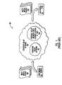
- Figure 3 illustrates a network 300 in which a multimedia source 301 communicates a plurality of multimedia packets 304 over heterogeneous networks 303 to a multimedia sink 302.
- the wide area network 262 described above with reference to Figure 2 is one example of a heterogeneous network, with the multimedia source 301 being the remote computer 260, and the multimedia sink 302 being the home entertainment system 210.
- the multimedia sink 302 may also be a personal digital assistant, a lap top computer, a desk top computer, a telephone, or any other device capable of receiving multimedia packets and rendering in real-time the associated multimedia information.
- the heterogeneous networks 303 may include three classifications of networks as follows:
- heterogeneous networks 303 are illustrated as having only one of each classification of networks, the principles of the present invention may be applied to heterogeneous networks that have zero or one or more of each classification of networks.
- the heterogeneous networks are illustrated such that multimedia packets 304 would traverse, in order, the constant delay network, the variable delay network with a common time base, and the variable delay network without a common time base. This configuration is provided for illustrative purposes only. The principles of the present invention apply regardless of the specific order of each network within the routing path of a multimedia packet.
- a gateway is provided between each network in the heterogeneous networks.
- gateway 331 receives multimedia packets from constant delay network 311, performs appropriate functions on those packets as described herein, and provides those packets over the variable delay network 312.
- gateway 332 receives multimedia packets from variable delay network 312, performs appropriate functions on those packets as described herein, and provides those packets over the variable delay network 313.
- the gateways receive multimedia packets from a previous network, reconfigure the multimedia packet if necessary to conform to the standards of the next network, and then transmit the potentially reconfigured multimedia packet onto the next network.
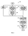
- Figure 4 illustrates a method 400 of performing constant delay communication of a stream of multimedia packets over heterogeneous networks in accordance with the present invention.
- Figure 3 illustrates an initial state of the heterogeneous networks before the method of Figure 4 commences.
- Figures 5 through 6 show successive states of the heterogeneous networks that result from the performance of the method of Figure 4 . Accordingly, the method of Figure 4 will be described with frequent reference to the network states illustrated in Figures 3 , 5 and 6 .
- FIG. 5 illustrates the network state of the heterogeneous networks after act 401 is complete.
- the modified form of the heterogeneous networks 303 of Figure 3 are illustrated as heterogeneous networks 503 in Figure 5 .
- the modified form of the variable delay network 313 of Figure 3 is illustrated as variable delay network 513 in Figure 5 .
- variable delay network 513 has a common time base 523, whereas the variable delay network 313 does not.
- each of the networks in the heterogeneous networks 503 should either be a constant delay network, or a variable delay network that has a common network time base.
- variable delay networks are emulated as one or more constant delay networks using the common time reckonings followed by each variable delay network (act 402). This may be accomplished by the link layer, the application layer or another layer in the gateway including a time stamp in the multimedia packet, the time stamp representing a time that follows the common time reckoning of the next variable delay network.
- the time stamp may be related to the time that the packet is to be rendered and may be, for example, the time that the packet is transmitted.
- the receiving device may then use the time stamp to determine when the packet should be displayed.
- the time stamp may also be used to determine what time the multimedia packet should be transmitted by subsequent gateways, or perhaps what time future time stamps should indicate for subsequent networks.
- the common time base 322 of the variable delay network 312 is used to emulate the variable delay network 312 as a constant delay network.
- the common time base 523 of the variable delay network 513 may be used to emulate the variable delay network 513 as a constant delay network.
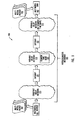
- Figure 6 illustrates the network state of the heterogeneous networks after act 402 is complete.
- the modified form of the heterogeneous networks 503 of Figure 5 are illustrated as heterogeneous networks 603 in Figure 6 .
- the emulated constant delay network 612 replaces the variable delay network 312 to emphasize its constant delay emulation.
- the emulated constant delay network 613 replaces the variable delay network 513 to emphasize its constant delay emulation.
- the network is sufficiently prepared to transmit multimedia packets from the multimedia source and the multimedia sink (act 403) in real-time.
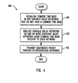
- the gateway may reformat or reconfigure the multimedia packet to conform with the requirements of the next network if necessary. In some cases, this may involve including a time stamp that conforms to the format of the next network and that represents an accurate time according to the time reckoning of the next network. Such time translation need not occur, however, if both the previous network and the next network recognize the same time reckoning, or if the next network is a constant delay network.
- the gateway When transitioning from a constant delay network to a constant delay network, the gateway should ensure that the packet is transmitted onto the next network at a relatively constant time period after the packet was received from the previous network. This transition may be accomplished without interpreting, manipulating, or creating time stamps for the packet.
- the gateway When transitioning from a constant delay network to a variable delay network, the gateway will receive the packet at a given receipt time from the constant delay network. The gateway will then generate a time stamp that represents a time according to the common time reckoning of the variable delay network, the time being equal to or having a relatively constant offset from the time that the packet was received from the constant delay network as measured using the common time reckoning of the variable delay network.
- the gateway When transitioning from a variable delay network to a constant delay network, the gateway will receive the packet and interpret the time stamp according to the time reckoning of the variable delay network to determine the time (according to the time reckoning of the gateway) when the packet should be transmitted onto the constant delay network. The gateway will then transmit the packet onto the constant delay network at the given transmit time.
- the gateway When transitioning from a variable delay network to another variable delay network, the gateway will leave the time stamp in the multimedia packet if both variable delay networks follow the same time reckoning and packet format. Otherwise, the gateway will translate the time stamp so that it represents a time according to the common time reckoning of the second variable delay network.
- a link layer controller In some variable delay networks, there is no provision for a link layer controller to maintain a common reckoning of time with other devices on the network. Accordingly, the application layer itself may maintain the common time reckoning across the devices, calculate the appropriate time stamp, and/or include the time stamp in the multimedia packet. Which of these tasks the application layer performs may depend on the capabilities of the link layer that the application layer uses to forward multimedia packets through the gateway.
- heterogeneous networks may emulate a constant delay network that allows for real-time communication of multimedia packets.
- the principles of the present invention provide for the delivery of multimedia packets regardless of the heterogenic nature of the networks that intervene between the multimedia source and the multimedia sink, even if some of the heterogeneous networks include variable delay network that do not themselves support a common notion of time.
- streaming multimedia data may be available regardless of the location of the user. Accordingly, the principles of the present invention represent a significant improvement over the state of the art.
- Figure 7 illustrates a network configuration 700 that includes a transmitter 720 and a receiver 721 and a variable delay network 704 that intervenes between the transmitter 720 and the receiver 721.
- the transmitter 720 includes a transmitter application 701 that stores a plurality of multimedia packets in a memory 707. For example, memory 707 stores two multimedia packets, a first multimedia packet 708 and a second multimedia packet 709.
- the transmitter 720 also includes a transmitter link layer controller 703 that actually retrieves the multimedia packets for transmission over the variable delay network 704.
- a variable delay interface 702 intervenes between the transmitter application 701 and the transmitter link layer controller 703.
- the receiver 721 includes a link layer controller 705, which receives the multimedia packets from the variable delay network 704 and provides those packets to the receiver application 706.
- the variable delay network 704 may be, for example, an IEEE 1394 serial bus network. It should be noted that the conventional IEC 61883-x technology allow for constant network emulation of a IEEE 1394 serial bus network using an AV link layer controller that provides IEC 61883-x support. However, this conventional constant delay emulation relies on a constant delay between the transmitter application dispatching the multimedia packets, and the transmitter link layer controller receiving the multimedia packet. However, as illustrated in Figure 7 , there is a variable delay interface 703 between the transmitter application 701 and the link layer controller 703. Therefore, there is no reason to believe that the conventional constant delay emulation methods using an AV link layer controller that provides IEC 61883-x support would work in the network configuration illustrated in Figure 7 .
- the variable delay interface 702 may be, for example, an undedicated PCI interface.
- the transmitter link layer controller 703 may be, for example, an OHCI link layer controller.
- the PCI interface has the advantage of being able to be shared among a variety of devices, not just the transmitter link layer controller 703. Accordingly, the PCI interface is well suited for general purpose computing systems.
- conventional technology does not provide for constant delay network emulation of a variable delay network when the transmitter of the variable delay network includes a variable delay interface between the transmitter application and the transmitter link layer controller.
- the principles of the present invention allow for a PCI interface with an OHCI link layer controller to be used in a transmitter while still emulating a constant delay network.
- Figure 8 illustrates a method 800 of a transmitter link layer controller emulating a constant delay network over a variable delay network despite the undedicated variable delay interface in accordance with the present invention.
- the method 800 of Figure 8 will be described with respect to the network configuration 700 of Figure 7 .
- the transmitter link layer controller 703 receives a first multimedia packet 708 from the transmitter application 701 (act 801).
- the transmitter application 701 included a first transmitter application time stamp 710 in the packet, the time stamp 710 representing the relative time that the information in the first multimedia packet 708 should be rendered by the receiver application 706 as represented in the time base followed by the transmitter application 701.
- the transmitter link layer controller 703 then includes another time stamp 714 in the first multimedia packet 708 (act 802).
- the new time stamp represents the time that the corresponding information should be rendering with reference to the network time base.
- the transmitter link layer controller 703 also receives information from the transmitter application 701 from which the transmitter link layer controller 703 may derive the frequency (act 803) of the time base used by the transmitter application with respect to the common time base (i.e., the network time base) recognized over devices on the variable delay network 704.
- the transmitter link layer controller 703 stores this information as frequency 712, and also stores the current time 713 in accordance with the common time base recognized over the variable delay network 704.
- the transmitter link layer controller also receives a second multimedia packet such as multimedia packet 709 from the transmitter application 701 over the variable delay interface 702 (act 804).
- the transmitter application 701 included a transmitter application time stamp 711 in the packet, the time stamp 711 representing the relative time that the information in the second multimedia packet 709 should be rendered by the receiver application 706, as represented in the time base followed by the transmitter application 701.
- the transmitter link layer controller 703 calculates a network time stamp 715 that represents the relative time that the information in the second multimedia packet should be rendered by the receiver application 706 in accordance with the common network time base (act 805).
- the transmitter link layer controller 703 then includes the calculated network time stamp 715 in the second multimedia packet 709 (act 806), and then dispatches the second multimedia packet 709 over the variable delay network 704 (act 807).
- the calculated network time stamp 715 may be included in the multimedia packet in accordance with the IEC 61883-x protocol.
- the receiver link layer controller 705 may then receive the multimedia packets and interpret the time stamp using the IEC 61883-x protocol.
- the link layer controller 705 may then forward the packets to the receiver application 706 which may then time the rendering of the corresponding information.
- FIG. 9 illustrates a network configuration 900 in which a transmitter application 901 controls the time base across a variable delay network 903.
- the transmitter application 901 is associated with a transmitter link layer controller 902 that stores a time base 913.
- a receiver application 905 is associated with a receiver link layer controller 904 that stores a time base 914, that is relatively synchronized with the time base 613.
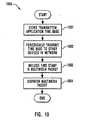
- Figure 10 illustrates a method 1000 for emulating a constant delay network over the variable delay network and will be described with respect to Figure 9 .
- the transmitter link layer controller 902 stores a transmitter application time base 913 received from the transmitter application 901 (act 1001).
- the transmitter link layer controller periodically transmits the transmitter application time base to one or more devices including the receiver link layer controller 904 over the variable delay network 903 (act 1002).
- Software that provides data asynchronously to the multimedia packets may perform the task of synchronization.
- the clock registers at the transmitter and receiver link layer controllers i.e., the time base 913 and the time base 914) may be kept synchronized.
- the transmitter link layer controller 902 includes the transmitter application time base in each packet that is to be transmitted over the variable delay network (act 1003) and then dispatches the packet over the network (act 1004).
- the receiver application 905 may then use the transmitter application time base in order to time the rendering of the corresponding information in the multimedia packets.
- An example of a variable delay network in which the method 1000 of Figure 10 may be implemented is an IEC 802.11 wireless network.
- the principles of the present invention provide for a means of emulating a constant delay network even over a group of heterogeneous networks that include variable delay networks that do not inherently support a common notion of time. Also, the principles of the present invention allow for constant delay network emulation on variable delay networks in which there is a variable delay interface between the transmitter application and the transmitter link layer controller, and in variable delay networks that have no inherent common network time base.
Abstract
Description
- 0001 The present invention relates to the field of network communications. More specifically, the present invention relates to the real-time communication of multimedia information over heterogeneous networks.
- 0002 Multimedia information includes information that is efficiently interpretable by one or more of the five human senses, but mostly by the human senses of sight and hearing. For example, video information is interpreted by the senses of sight and hearing. Audio information is interpreted by the sense of hearing. Some user interfaces such as Braille displays present information for interpretation by the sense of touch. However, with the advancement of appropriate user interfaces, multimedia information may also include taste and smell information as well.
- 0003 Often, multimedia information is time-sensitive and should be rendered at the same speed that the information is sampled within some minimal jitter tolerances. This type of multimedia presentation will often be referred herein as "real-time". For efficient real-time delivery of multimedia data, the networks between the multimedia source and the multimedia sink should be abstracted so that the networks as a whole function as a constant delay network.
- 0004
Figure 1 illustrates aconventional network 100 for delivering multimedia data in real-time. Amultimedia source 101 transmitsmultimedia packets 104 over aconstant delay network 103 to amultimedia sink 102. Of course, there is always some variance in the delay, however small, introduced by any network. However, a "constant delay" network is a network in which the delay variance introduced by the network is below the minimal jitter tolerances required to support real-time presentation of the multimedia data. - 0005 As illustrated in
Figure 1 , theconstant delay network 103 may include a number of different network types that follow different standards. Nevertheless, in order to support real-time multimedia data delivery, each component network must support the abstraction of the networks as a whole into the constant delay network. There are generally two classifications of networks that support this kind of abstraction into an amalgamated constant delay network. - 0006 One such classification is constant delay networks. Thus, for example, the
constant delay network 103 ofFigure 1 includes a componentconstant delay network 105. Constant delay networks receive multimedia data from a point on the network at a certain receive rate, and deliver the multimedia data to another point on the network at the same rate so that there is a relatively constant delay. A second such classification is variable delay networks that have a common notion of time. - 0007 It is possible even in such variable delay networks to emulate a constant delay network if the network supports a common notion of time across the network. For example, the IEEE 1394 serial bus is not inherently a constant delay network. However, the IEEE 1394 serial bus does support a common notion of time. The IEC 61883-x standard uses the common notion of time present in the IEEE 1394 serial bus to have the IEEE 1394 serial bus emulate a constant delay network to within the jitter tolerances required under the MPEG-2 standard.
- 0008 Referring to
Figure 1 , theconstant delay network 103 also may include avariable delay network 106. If a series of one or more contiguous variable delay networks is interposed between themultimedia source 101 and themultimedia sink 104, the series of variable delay networks may emulate a constant delay network if the string of variable delay networks shares a common notion or reckoning of time. - 0009 Thus, conventional methods allow for the real-time delivery of multimedia data over a network that includes both constant delay networks and variable delay networks that have a common notion of time. However, there is a third classification of networks that is not compatible with being a component network in an amalgamated constant delay network under conventional standards. That third classification is a variable delay network that does not have a common notion of time.
- 0010 Under conventional technology, real-time communication of multimedia data is not possible if one or more of the networks that must be traversed are variable delay networks that do not have a common notion of time. Accordingly, there exists no conventional infrastructure for seamlessly communicating multimedia over heterogeneous networks in real-time since those heterogeneous networks may include one or more variable delay networks that contain no common time reference across the network. Establishing such an infrastructure would allow for better access to multimedia content regardless of the heterogenic nature of the networks that intervene between the multimedia source and the multimedia sink.
- 0011 The present invention extends to the real-time communication of multimedia data over heterogeneous networks that may include constant delay networks, variable delay networks that have a common reckoning of time, and variable delay networks that do not have a common reckoning of time. Currently, real-time communication of multimedia data may be accomplished point-to-point over specific networks. However, there is no conventional way of communicating such data in real-time over heterogeneous networks that include variable delay networks that have no common reckoning of time.
- 0012 If there are any variable delay networks in the heterogeneous networks in which there is no common reckoning of time, a common reckoning of time is established in each of those networks. Then, the variable delay networks are emulated as one or more constant delay networks using the specific common time reckoning present in each variable delay network. Thus, the principles of the present invention allow for the real-time communication of multimedia information over heterogeneous networks. By so doing, a user may more flexibly access multimedia data in real-time regardless of the location of the individual.
- 0013 In one aspect of the present invention, a constant delay network is emulated over a variable delay network despite the fact that the transmitter includes a transmitter application that interfaces with a link layer device driver over a variable delay interface. The transmitter application provides multimedia packets for transmission over the variable delay network. In addition, the transmitter application provides the multimedia packets with time stamps that represent the time according to the reckoning of the transmitter application. When the transmitter link layer device receives the multimedia packet, it calculates a new time stamp that is in accordance with a network time base, the new time stamp being based on the time stamp provided by the transmitter application. The receiver link layer controller then uses the new time stamp to evaluate the rendering time of the corresponding information in the packet.
- 0014 Another aspect of the invention permits for communication over a variable delay network that does not inherently have a time base. Instead, the transmitter application periodically transmits a current time to various receiver devices on the network in order to synchronize the devices on the network. Then, the transmitter includes a time stamp that follows the synchronized time in order to permit the information in the multimedia packets to be presented at the appropriate time.
- 0015 Additional features and advantages of the invention will be set forth in the description, which follows, and in part will be obvious from the description, or may be learned by the practice of the invention. The features and advantages of the invention may be realized and obtained by means of the instruments and combinations particularly pointed out in the appended claims. These and other features of the present invention will become more fully apparent from the following description and appended claims, or may be learned by the practice of the invention as set forth hereinafter.
- 0016 In order that the manner in which the above-recited and other advantages and features of the invention are obtained, a more particular description of the invention briefly described above will be rendered by reference to specific embodiments thereof, which are illustrated, in the appended drawings. Understanding that these drawings depict only typical embodiments of the invention and are not therefore to be considered to be limiting of its scope, the invention will be described and explained with additional specificity and detail through the use of the accompanying drawings in which:
- 0017
Figure 1 schematically illustrates a constant delay network that supports real-time multimedia communication in accordance with the prior art; - 0018
Figure 2 illustrates an exemplary system that provides a suitable operating environment for the present invention; - 0019
Figure 3 schematically illustrates multimedia communication over a heterogeneous network that may include constant delay networks, variable delay networks with a common network time base, and variable delay networks without a common network time base; - 0020
Figure 4 illustrates a flowchart of a method of performing constant delay communication of multimedia packets over a heterogeneous network; - 0021
Figure 5 illustrates the heterogeneous network ofFigure 3 in which the variable delay networks that did not have a common network time base are provided with a common network time base; - 0022
Figure 6 illustrates the heterogeneous network ofFigure 5 in which the variable delay networks emulate constant delay networks using the common network time base; - 0023
Figure 7 illustrates a variable delay network in which there is an undedicated variable delay interface between the transmitter application and the transmitter link layer controller as when the variable delay interface is a PCI interface; - 0024
Figure 8 illustrates a method for emulating a constant delay network in a variable delay network even if there is a variable delay interface between the transmitter application and the transmitter link layer controller; - 0025
Figure 9 illustrates a variable delay network in which a common time base is established; and - 0026
Figure 10 illustrates a method of emulating a constant delay network using a variable delay network that is not conventionally equipped with a common network time base. - 0027 The present invention extends to the real-time communication of multimedia data over heterogeneous networks that may include constant delay networks, variable delay networks that have a common reckoning of time, and variable delay networks that do not have a common reckoning of time. If there are any variable delay networks in which there is no common reckoning of time, a common reckoning of time is established in each of those networks. Then, the common reckonings of times may be used to emulate the variable delay networks as one or more constant delay networks.
- 0028 The embodiments of the present invention may comprise a special purpose or general-purpose processing device or computer including various computer hardware components, as discussed in greater detail below. The embodiments may further comprise multiple computers linked in a networked environment. Set top boxes that enhance the capabilities of conventional televisions represent an example of a special purpose computer.
- 0029 Embodiments within the scope of the present invention also include computer-readable media for carrying or having computer-executable instructions or data structures stored thereon. Such computer-readable media can be any available media that can be accessed by a general purpose or special purpose computer. By way of example, and not limitation, such computer-readable media can comprise physical storage media such as RAM, ROM, EEPROM, CD-ROM or other optical disk storage, magnetic disk storage or other magnetic storage devices, or any other medium that can be used to carry or store desired program code means in the form of computer-executable instructions or data structures and that can be accessed by a general purpose or special purpose computer.
- 0030 When information is transferred or provided over a network or another communications connection (either hardwired, wireless, or a combination of hardwired or wireless) to a computer, the computer properly views the connection as a computer-readable medium. Thus, such a connection is also properly termed a computer-readable medium. Combinations of the above should also be included within the scope of computer-readable media. Computer-executable instructions comprise, for example, instructions and data which cause a general purpose computer, special purpose computer, or special purpose processing device to perform a certain function or group of functions.
- 0031 The invention will be described in the general context of computer-executable instructions, such as program modules, being executed by set-top boxes or other computers. Generally, program modules include routines, programs, objects, components, data structures, etc. that perform particular tasks or implement particular abstract data types. The sequence of instructions implemented in a particular data structure or program module represents examples of corresponding acts for implementing the functions or steps described herein.
- 0032
Figure 2 and the corresponding discussion are intended to provide a general description of a suitable environment in which the invention may be implemented. In the discussion, reference is made to a home entertainment system that may be used for displaying and/or recording programming. For purposes of this description and in the claims, a "home entertainment system" may be a display unit, such as a television screen, coupled to a processing device for performing the data processing acts and steps disclosed herein, or may include any number of interconnected consumer electronic devices, one of which having a processing device for performing the data processing disclosed herein. - 0033 Examples of such consumer electronic devices include a video cassette recorder ("VCR"), a video game system, a stereo system, a television or monitor with data processing capabilities, a cable television box, a digital satellite system receiver ("DSS"), a digital video broadcasting system ("DVB"), a digital versatile disc system ("DVD"), a compact disk read-only memory system ("CD-ROM"), a set-top box that serves as an Internet terminal, and any other device capable of processing data as described herein. Furthermore, the term "home entertainment system" is to be understood as a term that broadly describes a television-viewing or music listening environment, whether it is located in a viewer's home, at a place of business, in the public, or at any other location. Also for purposes of this description and in the claims, the term "programming" includes both the viewable and non-viewable portions of moving image data and/or its associated sound data.
- 0034 In one embodiment, the present invention is implemented in a system that uses a conventional television screen or other display unit to display information and includes a WebTV® set-top box or a similar Internet terminal that has been adapted to perform the operations that include composing, sending and receiving email, browsing the World Wide Web ("Web''), accessing other segments of the Internet, and otherwise displaying information. An Internet terminal may use standard telephone lines, Integrated Services Digital Network (ISDN) lines, cable lines associated with cable television service, or the like to connect to the Internet or other wide area networks.
- 0035
Figure 2 illustrates ahome entertainment system 210 that includes amanagement system 212, adisplay device 214 and anaudio system 216.Management system 212 may be a set-top box or Internet terminal that has been adapted to perform the operations disclosed herein.Management system 212 may be integrally positioned with or separate fromdisplay device 214, which may be a high definition television display, a standard television display, a flat panel display, a projection device, an interface involving direct neural stimulation, a computer monitor, or any other device capable of displaying viewable video image data.Audio system 216 may be a speaker, a stereo system, or any device capable of emitting sound data, and similarly may be integrally positioned with or separate fromdisplay device 214. - 0036
Management system 212 includes asignal input 218, which receives programming from asignal source 220. The programming is transmitted fromsignal source 220 to signalinput 218 via aprogramming input line 222, which can be a cable or optic connection, a terrestrial antenna system, a satellite system, or any device or system capable of transmitting programming tohome management system 212. - 0037 The
signal source 220 may be either a single channel signal source or a multiple channel signal source. A single channel signal source provides programming from a recorded medium, such as a videocassette, compact disc, etc. Examples of a single channel signal source include a VCR, a DVD, and the like. Alternatively, a multiple channel signal source includes any system or device that is capable of sending a signal that may be received by a satellite receiver, a cable or optic connection, a terrestrial antenna, or the like. Examples of a multiple channel signal source include DSS/DVB, a cable box, locally broadcast programming (i.e. programming broadcast using UHF or VHF), and the like. - 0038 While
Figure 2 illustrateshome entertainment system 210 as having a singleprogramming input line 222 and asingle signal source 220, there may also be a plurality of programming input lines that transmit programming from a plurality of signal sources. In such embodiments, the home entertainment system may receive the programming from one signal source or from a plurality of signal sources at a time. - 0039
Management system 212 also includes auser input interface 224, which receives input from aninput device 226, such as a remote control, external special purpose or general-purpose processing device or computer, keyboard, microphone, mouse, or any other device capable of generating electronic instructions formanagement system 212.Input device 226 is communicatively coupled tomanagement system 212 over aninput link 228 so as to enable such control.Input device 226 generates electronic instructions overinput link 228 in response to preprogrammed data or in response to a viewer pressing buttons oninput device 226.Input device 226 may also control Web browser software withinmanagement system 212 as whenmanagement system 212 is a set-top box or an Internet terminal that has been adapted to perform the operations disclosed herein. For instance,input device 226 may be programmed to turn onhome entertainment system 210 and to tunemanagement system 212 to a channel. - 0040
Figure 2 illustrates asignal recorder 230, which is capable of receiving video and/or audio data and recording the data on a storage medium. Video signals are transmitted to displaydevice 214 and/orsignal recorder 230 byvideo image links audio links management system 212 toaudio system 216 and/or to signalrecorder 230. - 0041 The operation of
management system 212 is controlled by a central processing unit ("CPU"), illustrated asprocessing unit 236, which is coupled to an application-specific integrated circuit ("ASIC") 238 via system bus 240 and uses computer-executable instructions implemented in software and/or hardwired logic circuitry.Processing unit 236 andASIC 238 are also coupled via a system bus 240 to various other system components, includingsystem memory 242,mass storage interface 244,user interface 224 andsignal input 218.Processing unit 236 may execute software designed to implement features ofmanagement system 212 including features of the present invention. - 0042
ASIC 238 contains circuitry that is used to implement certain functions ofmanagement system 212. Instructions, data, and other program modules necessary for the operation ofprocessing unit 236 and necessary for the operation of theASIC 238 may be stored inmass storage device 250 and/orsystem memory 242, which includes read-only memory ("ROM") 246 and random-access memory ("RAM") 248.System memory 242 is coupled to system bus 240 andmass storage device 250 is coupled tomass storage interface 244, which is in turn also coupled to system bus 240. Thus,ROM 246,RAM 248 andmass storage device 250 are communicatively coupled toASIC 238 so as to be readable byASIC 238 and so that data may be written fromASIC 238 to RAM 248 and tomass storage device 250.Mass storage device 250 may be a magnetichard disk 252, but may also be any of the other computer-readable media referenced above. - 0043 Any desired computer-readable instructions or data, including
application programs 254,other program modules 256, and an electronic programming guide ("EPG") 258, which specifies the broadcast times and channels of programs can be stored inmass storage device 250. - 0044
Mass storage device 250 may also be used to recordvideo data 253, in which case,management system 212 performs the functions of a digital video recorder. Digital video data may be received byhome entertainment system 210 from a variety of sources includingsignal source 220,remote computer 260,video game 268,input device 226 and the Internet. - 0045 EPG data may be obtained in a variety of manners. For instance, the EPG data can be supplied to
management system 212 by aremote computer 260, such as a server, or from devices on the Internet and stored onmass storage device 250. The EPG data may be supplied on a regular basis to continually maintain a current schedule of programming at themanagement system 212. Alternatively, the EPG may be delivered tohome entertainment system 210 by using a direct-dial communication over standard telephone lines, or by using data transmission over the cable television infrastructure, a satellite network, an over-the-air broadcast or any other available medium, including those previously mentioned. - 0046 In the embodiment where
management system 212 is associated with the Internet,management system 212 may communicate withremote computer 260 via wide area network ("WAN") 262 using a variety of techniques, including interposingserial port interface 264 between the system bus 240 and amodem 266, using a wireless link, or other means for establishing communications over a WAN that may be internal or external tomanagement system 212.Management device 212 is also capable of transmitting information via the Internet by direct-dial communication over standard telephone lines, or by using any other available communication medium. - 0047 While
serial port interface 264 may be utilized to connect amodem 266 for communicating across a WAN, serial port interface may also be utilized to connect other consumer electronic devices, such asvideo game 268, and/or various input devices, such as a keyboard (not shown) or joystick (not shown), tomanagement device 212. - 0048 Referring now to signal
input 218, if the signal onprogramming input line 222 includes multiple channels, atuner 270 included insignal input 218 tunes to a selected channel in the signal.Multiple tuners 270 can be used to provide enhanced viewing features, such as picture-in-picture, recording one channel while viewing another, and recording a plurality of channels simultaneously. Asignal decoder 272 may convert video data from an analog format to a digital format, from a digital format to an analog format, or convent between varying digital formats, in the event thatASIC 238 andtuner 270 employ different formats.Video decoder 272 may also decode video data from a compressed video format (e.g. MPEG). In embodiments where themanagement system 212 includesmultiple tuners 270,management system 212 may also includemultiple signal decoders 272 to perform the operations disclosed herein. - 0049
Management system 212 may also includevideo output 274, which may include a video converter that switches between analog and digital formats as necessary when providing video data overvideo links audio output 276 can include an audio converter to provide the necessary switching between analog and digital formats acrossaudio links - 0050 While
Figure 2 and the corresponding discussion above provide a general description of a suitable environment in which the invention may be implemented, it will be appreciated that the features of the present invention disclosed herein may be practiced in association with a variety of different system configurations. - 0051
Figure 3 illustrates anetwork 300 in which amultimedia source 301 communicates a plurality ofmultimedia packets 304 over heterogeneous networks 303 to amultimedia sink 302. Thewide area network 262 described above with reference toFigure 2 is one example of a heterogeneous network, with themultimedia source 301 being theremote computer 260, and themultimedia sink 302 being thehome entertainment system 210. However, themultimedia sink 302 may also be a personal digital assistant, a lap top computer, a desk top computer, a telephone, or any other device capable of receiving multimedia packets and rendering in real-time the associated multimedia information. - 0052 The heterogeneous networks 303 may include three classifications of networks as follows:
- 1) constant delay networks
(e.g., constant delay network 311); - 2) variable delay networks that have a common time base
(e.g.,variable delay network 312 that has common time base 322); and - 3) variable delay networks that do not have a common time base
(e.g.,. variable delay network 313 that does not have a common time base). - 0053 Although the heterogeneous networks 303 are illustrated as having only one of each classification of networks, the principles of the present invention may be applied to heterogeneous networks that have zero or one or more of each classification of networks. The heterogeneous networks are illustrated such that
multimedia packets 304 would traverse, in order, the constant delay network, the variable delay network with a common time base, and the variable delay network without a common time base. This configuration is provided for illustrative purposes only. The principles of the present invention apply regardless of the specific order of each network within the routing path of a multimedia packet. - 0054 In order to transition the multimedia packets from one network to the next, a gateway is provided between each network in the heterogeneous networks. For example,
gateway 331 receives multimedia packets fromconstant delay network 311, performs appropriate functions on those packets as described herein, and provides those packets over thevariable delay network 312. In addition,gateway 332 receives multimedia packets fromvariable delay network 312, performs appropriate functions on those packets as described herein, and provides those packets over the variable delay network 313. The gateways receive multimedia packets from a previous network, reconfigure the multimedia packet if necessary to conform to the standards of the next network, and then transmit the potentially reconfigured multimedia packet onto the next network. - 0055
Figure 4 illustrates amethod 400 of performing constant delay communication of a stream of multimedia packets over heterogeneous networks in accordance with the present invention.Figure 3 illustrates an initial state of the heterogeneous networks before the method ofFigure 4 commences.Figures 5 through 6 show successive states of the heterogeneous networks that result from the performance of the method ofFigure 4 . Accordingly, the method ofFigure 4 will be described with frequent reference to the network states illustrated inFigures 3 ,5 and6 . - 0056 Initially, a common time reckoning is established in those variable delay networks in the heterogeneous networks that do not already have a common network time base (act 401).
Figure 5 illustrates the network state of the heterogeneous networks afteract 401 is complete. The modified form of the heterogeneous networks 303 ofFigure 3 are illustrated as heterogeneous networks 503 inFigure 5 . The modified form of the variable delay network 313 ofFigure 3 is illustrated asvariable delay network 513 inFigure 5 . Note thatvariable delay network 513 has acommon time base 523, whereas the variable delay network 313 does not. At this stage, each of the networks in the heterogeneous networks 503 should either be a constant delay network, or a variable delay network that has a common network time base. - 0057 Returning to
method 400 ofFigure 4 , the variable delay networks are emulated as one or more constant delay networks using the common time reckonings followed by each variable delay network (act 402). This may be accomplished by the link layer, the application layer or another layer in the gateway including a time stamp in the multimedia packet, the time stamp representing a time that follows the common time reckoning of the next variable delay network. The time stamp may be related to the time that the packet is to be rendered and may be, for example, the time that the packet is transmitted. The receiving device may then use the time stamp to determine when the packet should be displayed. The time stamp may also be used to determine what time the multimedia packet should be transmitted by subsequent gateways, or perhaps what time future time stamps should indicate for subsequent networks. Referring toFigure 5 , thecommon time base 322 of thevariable delay network 312 is used to emulate thevariable delay network 312 as a constant delay network. In addition, thecommon time base 523 of thevariable delay network 513 may be used to emulate thevariable delay network 513 as a constant delay network. - 0058
Figure 6 illustrates the network state of the heterogeneous networks afteract 402 is complete. The modified form of the heterogeneous networks 503 ofFigure 5 are illustrated as heterogeneous networks 603 inFigure 6 . The emulatedconstant delay network 612 replaces thevariable delay network 312 to emphasize its constant delay emulation. In addition, the emulatedconstant delay network 613 replaces thevariable delay network 513 to emphasize its constant delay emulation. Now the network is sufficiently prepared to transmit multimedia packets from the multimedia source and the multimedia sink (act 403) in real-time. - 0059 As a multimedia packet transitions from one network to the next in the heterogeneous networks, the gateway may reformat or reconfigure the multimedia packet to conform with the requirements of the next network if necessary. In some cases, this may involve including a time stamp that conforms to the format of the next network and that represents an accurate time according to the time reckoning of the next network. Such time translation need not occur, however, if both the previous network and the next network recognize the same time reckoning, or if the next network is a constant delay network.
- 0060 When transitioning from a constant delay network to a constant delay network, the gateway should ensure that the packet is transmitted onto the next network at a relatively constant time period after the packet was received from the previous network. This transition may be accomplished without interpreting, manipulating, or creating time stamps for the packet.
- 0061 When transitioning from a constant delay network to a variable delay network, the gateway will receive the packet at a given receipt time from the constant delay network. The gateway will then generate a time stamp that represents a time according to the common time reckoning of the variable delay network, the time being equal to or having a relatively constant offset from the time that the packet was received from the constant delay network as measured using the common time reckoning of the variable delay network.
- 0062 When transitioning from a variable delay network to a constant delay network, the gateway will receive the packet and interpret the time stamp according to the time reckoning of the variable delay network to determine the time (according to the time reckoning of the gateway) when the packet should be transmitted onto the constant delay network. The gateway will then transmit the packet onto the constant delay network at the given transmit time.
- 0063 When transitioning from a variable delay network to another variable delay network, the gateway will leave the time stamp in the multimedia packet if both variable delay networks follow the same time reckoning and packet format. Otherwise, the gateway will translate the time stamp so that it represents a time according to the common time reckoning of the second variable delay network.
- 0064 In some variable delay networks, there is no provision for a link layer controller to maintain a common reckoning of time with other devices on the network. Accordingly, the application layer itself may maintain the common time reckoning across the devices, calculate the appropriate time stamp, and/or include the time stamp in the multimedia packet. Which of these tasks the application layer performs may depend on the capabilities of the link layer that the application layer uses to forward multimedia packets through the gateway.
- 0065 In this manner, even heterogeneous networks may emulate a constant delay network that allows for real-time communication of multimedia packets. Thus, the principles of the present invention provide for the delivery of multimedia packets regardless of the heterogenic nature of the networks that intervene between the multimedia source and the multimedia sink, even if some of the heterogeneous networks include variable delay network that do not themselves support a common notion of time. Thus, streaming multimedia data may be available regardless of the location of the user. Accordingly, the principles of the present invention represent a significant improvement over the state of the art.
- 0066 Various examples are now provided of how to emulate a constant delay network from a variable delay network. In particular,
Figure 7 illustrates anetwork configuration 700 that includes atransmitter 720 and areceiver 721 and avariable delay network 704 that intervenes between thetransmitter 720 and thereceiver 721. - 0067 The
transmitter 720 includes atransmitter application 701 that stores a plurality of multimedia packets in amemory 707. For example,memory 707 stores two multimedia packets, afirst multimedia packet 708 and asecond multimedia packet 709. Thetransmitter 720 also includes a transmitterlink layer controller 703 that actually retrieves the multimedia packets for transmission over thevariable delay network 704. Avariable delay interface 702 intervenes between thetransmitter application 701 and the transmitterlink layer controller 703. Thereceiver 721 includes alink layer controller 705, which receives the multimedia packets from thevariable delay network 704 and provides those packets to thereceiver application 706. - 0068 The
variable delay network 704 may be, for example, an IEEE 1394 serial bus network. It should be noted that the conventional IEC 61883-x technology allow for constant network emulation of a IEEE 1394 serial bus network using an AV link layer controller that provides IEC 61883-x support. However, this conventional constant delay emulation relies on a constant delay between the transmitter application dispatching the multimedia packets, and the transmitter link layer controller receiving the multimedia packet. However, as illustrated inFigure 7 , there is avariable delay interface 703 between thetransmitter application 701 and thelink layer controller 703. Therefore, there is no reason to believe that the conventional constant delay emulation methods using an AV link layer controller that provides IEC 61883-x support would work in the network configuration illustrated inFigure 7 . - 0069 The
variable delay interface 702 may be, for example, an undedicated PCI interface. In this case, the transmitterlink layer controller 703 may be, for example, an OHCI link layer controller. The PCI interface has the advantage of being able to be shared among a variety of devices, not just the transmitterlink layer controller 703. Accordingly, the PCI interface is well suited for general purpose computing systems. However, conventional technology does not provide for constant delay network emulation of a variable delay network when the transmitter of the variable delay network includes a variable delay interface between the transmitter application and the transmitter link layer controller. The principles of the present invention, however, allow for a PCI interface with an OHCI link layer controller to be used in a transmitter while still emulating a constant delay network. - 0070
Figure 8 illustrates amethod 800 of a transmitter link layer controller emulating a constant delay network over a variable delay network despite the undedicated variable delay interface in accordance with the present invention. Themethod 800 ofFigure 8 will be described with respect to thenetwork configuration 700 ofFigure 7 . - 0071 The transmitter
link layer controller 703 receives afirst multimedia packet 708 from the transmitter application 701 (act 801). Thetransmitter application 701 included a first transmitterapplication time stamp 710 in the packet, thetime stamp 710 representing the relative time that the information in thefirst multimedia packet 708 should be rendered by thereceiver application 706 as represented in the time base followed by thetransmitter application 701. The transmitterlink layer controller 703 then includes anothertime stamp 714 in the first multimedia packet 708 (act 802). The new time stamp represents the time that the corresponding information should be rendering with reference to the network time base. - 0072 The transmitter
link layer controller 703 also receives information from thetransmitter application 701 from which the transmitterlink layer controller 703 may derive the frequency (act 803) of the time base used by the transmitter application with respect to the common time base (i.e., the network time base) recognized over devices on thevariable delay network 704. The transmitterlink layer controller 703 stores this information asfrequency 712, and also stores thecurrent time 713 in accordance with the common time base recognized over thevariable delay network 704. - 0073 The transmitter link layer controller also receives a second multimedia packet such as
multimedia packet 709 from thetransmitter application 701 over the variable delay interface 702 (act 804). Thetransmitter application 701 included a transmitterapplication time stamp 711 in the packet, thetime stamp 711 representing the relative time that the information in thesecond multimedia packet 709 should be rendered by thereceiver application 706, as represented in the time base followed by thetransmitter application 701. - 0074 The transmitter
link layer controller 703 then calculates anetwork time stamp 715 that represents the relative time that the information in the second multimedia packet should be rendered by thereceiver application 706 in accordance with the common network time base (act 805). The calculation is based on the first transmitterapplication time stamp 710, the second transmitterapplication time stamp 711, thefrequency 712, and the firstnetwork time stamp 714. More specifically, this calculation may be made according to the following formula:
where: - old_network_time = the stored value of the time stamped in the last packet;
- old_STB_time = the stored value of the software time base provided in the last packet;
- new_STB_time = the value of the software time base read from the current packet; and
- frequency = the stored software time base frequency.
- 0075 The transmitter
link layer controller 703 then includes the calculatednetwork time stamp 715 in the second multimedia packet 709 (act 806), and then dispatches thesecond multimedia packet 709 over the variable delay network 704 (act 807). The calculatednetwork time stamp 715 may be included in the multimedia packet in accordance with the IEC 61883-x protocol. The receiverlink layer controller 705 may then receive the multimedia packets and interpret the time stamp using the IEC 61883-x protocol. Thelink layer controller 705 may then forward the packets to thereceiver application 706 which may then time the rendering of the corresponding information. - 0076
Figure 9 illustrates anetwork configuration 900 in which atransmitter application 901 controls the time base across avariable delay network 903. Thetransmitter application 901 is associated with a transmitterlink layer controller 902 that stores atime base 913. Areceiver application 905 is associated with a receiverlink layer controller 904 that stores atime base 914, that is relatively synchronized with thetime base 613. - 0077
Figure 10 illustrates amethod 1000 for emulating a constant delay network over the variable delay network and will be described with respect toFigure 9 . The transmitterlink layer controller 902 stores a transmitterapplication time base 913 received from the transmitter application 901 (act 1001). - 0078 The transmitter link layer controller periodically transmits the transmitter application time base to one or more devices including the receiver
link layer controller 904 over the variable delay network 903 (act 1002). Software that provides data asynchronously to the multimedia packets may perform the task of synchronization. In this manner, the clock registers at the transmitter and receiver link layer controllers (i.e., thetime base 913 and the time base 914) may be kept synchronized. - 0079 The transmitter
link layer controller 902 includes the transmitter application time base in each packet that is to be transmitted over the variable delay network (act 1003) and then dispatches the packet over the network (act 1004). Thereceiver application 905 may then use the transmitter application time base in order to time the rendering of the corresponding information in the multimedia packets. An example of a variable delay network in which themethod 1000 ofFigure 10 may be implemented is an IEC 802.11 wireless network. - 0080 Therefore, the principles of the present invention provide for a means of emulating a constant delay network even over a group of heterogeneous networks that include variable delay networks that do not inherently support a common notion of time. Also, the principles of the present invention allow for constant delay network emulation on variable delay networks in which there is a variable delay interface between the transmitter application and the transmitter link layer controller, and in variable delay networks that have no inherent common network time base.
- 0081 The present invention may be embodied in other specific forms without departing from its spirit or essential characteristics. The described embodiments are to be considered in all respects only as illustrative and not restrictive. The scope of the invention is, therefore, indicated by the appended claims rather than by the foregoing description. All changes, which come within the meaning and range of equivalency of the claims, are to be embraced within their scope.
- 0082 What is claimed and desired secured by United States Letters Patent is:
- The following is a list of further preferred embodiments of the invention:
- Embodiment 1: A method of performing constant delay communication of a stream of multimedia packets from a multimedia source over heterogeneous networks including a plurality of variable delay networks to a multimedia sink even though one or more of the variable delay networks do not themselves provide for a common reckoning of time in the variable delay network, the method for use in a network system that includes the multimedia source and the multimedia sink, the multimedia source transmitting the stream of multimedia packets to the multimedia sink over a plurality of heterogeneous networks, the method comprising:
- establishing a common time reckoning in all of the variable delay networks that do not themselves provide for a common time reckoning;
- emulating the plurality of variable delay networks as one or more constant delay networks using the specific common time reckonings present in the plurality of variable delay networks, wherein the heterogeneous networks as a whole emulates a constant delay network; and
- transmitting a multimedia packet over the heterogeneous networks.
- Embodiment 2: The method in accordance with
embodiment 1, further comprising:- receiving the multimedia packet from a previous network in the heterogeneous networks;
- as the multimedia packet transitions from the previous network to a next network in the heterogeneous networks, configuring the multimedia packet if necessary to conform with the requirements of the next network if the multimedia packet does not already conform with the requirements of the next network; and
- transmitting the reconfigured multimedia packet onto the next network.
- Embodiment 3: The method in accordance with embodiment 2, further comprising:
- repeating the receiving of the multimedia packet from a previous network, the configuring of the multimedia packet if necessary, and the transmitting of the reconfigured multimedia packet onto the next network for each network transition as the multimedia packet traverses the heterogeneous networks from the multimedia source to the multimedia sink.
- Embodiment 4: The method in accordance with embodiment 2 or 3, wherein the next network is a variable delay network, wherein the configuring of the multimedia packet if necessary comprises:
- generate a time stamp that represents a time in accordance with a common time reckoning of the variable delay network; and
- including the time stamp in the multimedia packet.
- Embodiment 5: The method in accordance with embodiment 4, wherein the including of the time stamp in the multimedia packet is performed by the link layer.
- Embodiment 6: The method in accordance with embodiment 4, wherein the including of the time stamp in the multimedia packet comprises:
- including the time stamp in the multimedia packet before control of the multimedia packet transfers to the link layer associated with the next network.
- Embodiment 7: The method in accordance with embodiment 6, wherein the including of the time stamp in the multimedia packet before control of the multimedia packet transfers to the link layer comprises:
- an application layer including the time stamp in the multimedia packet.
- Embodiment 8: A method of a transmitter link layer controller emulating a constant delay network over a variable delay network despite an undedicated variable delay interface, the method for use in the variable delay network that includes a transmitter and a receiver, a transmitter application associated with the transmitter configured to transmit a stream of multimedia packets through the transmitter link layer controller, over the variable delay network, through a receiver link layer controller to a receiver application associated with the receiver, the transmitter link layer controller having the undedicated variable delay interface with the transmitter application, the transmitter link layer controller and the receiver link layer controller being substantially synchronized in accordance with a common network time base, the method comprising:
- receiving a first multimedia packet from the transmitter application, the first multimedia packet including a first transmitter application time stamp, which represents the relative time that the information in the first multimedia packet should be rendered by the receiver application in accordance with a transmitter application time base;
- including in the first multimedia packet a first network time stamp, which represents the relative time that the information in the first multimedia packet should be rendered by the receiver application in accordance with the common network time base;
- receiving data representing a frequency of the transmitter application time base;
- receiving a second multimedia packet from the transmitter application, the second multimedia packet including a second transmitter application time stamp, which represents the relative time that the information in the second multimedia packet should be rendered by the receiver application in accordance with the transmitter application time base;
- calculating a second network time stamp representing the relative time that the information in the second multimedia packet should be rendered by the receiver application in accordance with the common network time base, the calculation based on the first transmitter application time stamp, the second transmitter application time stamp, the frequency, and the first network time stamp;
- including the second network time stamp in the second multimedia packet; and
- dispatching the second multimedia packet to the receiver application.
- Embodiment 9: The method in accordance with embodiment 8, wherein the variable delay network is an IEEE 1394 compliant network, the transmitter link layer controller comprises an OHCl link layer controller, and the undedicated variable delay interface comprises a PCI interface.
- Embodiment 10: The method in accordance with embodiment 8 or 9, wherein including the second network time stamp in the second multimedia packet is performed in accordance with the IEC 61883 protocol.
- Embodiment 11: A method of a transmitter emulating a constant delay network over a variable delay network, the method for use in the variable delay network that includes the transmitter and a receiver, a transmitter application associated with the transmitter configured to transmit a stream of multimedia packets through a transmitter link layer controller, over the variable delay network, through a receiver link layer controller to a receiver application associated with the receiver, the method comprising:
- storing a transmitter application time base in a register;
- periodically transmitting the transmitter application time base to one or more other devices in the variable delay network;
- including a transmitter application time stamp in a multimedia packet, the transmitter application time stamp representing the relative time that the information in the multimedia packet should be rendered by the receiver application; and
- dispatching the multimedia packet to the receiver application.
- Embodiment 12: The method in accordance with embodiment 11, wherein the variable delay network is an IEEE 802.11 compliant network.
- Embodiment 13: A computer program product comprising a computer readable medium having stored thereon computer-executable instructions for performing all the steps of the method according to any one of
embodiments 1 to 12, when run on a computer. - Embodiment 14: The computer program product in accordance with embodiment 17, wherein the computer-readable medium is one or more physical storage media.
Claims (7)
- A method of performing constant delay communication of a stream of multimedia packets from a multimedia source over heterogeneous networks including a plurality of variable delay networks to a multimedia sink even though one or more of the variable delay networks do not themselves provide for a common reckoning of time in the variable delay network, the method for use in a network system that includes the multimedia source and the multimedia sink, the multimedia source transmitting the stream of multimedia packets to the multimedia sink over a plurality of heterogeneous networks with gateways between them, the method comprising:establishing a common time reckoning in all of the variable delay networks that do not themselves provide for a common time reckoning;receiving a multimedia packet from a previous network of the heterogeneous networks at a gateway between the previous network and a next network of the heterogeneous networks, the next network being a variable delay network;configuring the multimedia packet if necessary to conform with the requirements of the next network by including, by the gateway, a time stamp in the multimedia packet, the time stamp representing a time in accordance with the common time reckoning of the next network; andtransmitting the reconfigured multimedia packet onto the next network.
- The method in accordance with claim 1, further comprising:repeating the receiving of the multimedia packet from a previous network, the configuring of the multimedia packet if necessary, and the transmitting of the reconfigured multimedia packet onto the next network for each network transition as the multimedia packet traverses the heterogeneous networks from the multimedia source to the multimedia sink.
- The method in accordance with claim 1 or 2, wherein the including of the time stamp in the multimedia packet is performed by the link layer.
- The method in accordance with claim 1 or 2, wherein the including of the time stamp in the multimedia packet comprises:including the time stamp in the multimedia packet before control of the multimedia packet transfers to the link layer associated with the next network.
- The method in accordance with claim 4, wherein the including of the time stamp in the multimedia packet before control of the multimedia packet transfers to the link layer comprises:an application layer including the time stamp in the multimedia packet.
- A computer program product comprising a computer readable medium having stored thereon computer-executable instructions for performing all the steps of the method according to any one of claims 1 to 5, when run on a computer.
- A computer program product in accordance with claim 6, wherein the computer-readable medium is one or more physical storage media.
Applications Claiming Priority (2)
| Application Number | Priority Date | Filing Date | Title |
|---|---|---|---|
| US09/836,834 US6970481B2 (en) | 2001-04-17 | 2001-04-17 | Methods and systems for distributing multimedia data over heterogeneous networks |
| EP02006409A EP1251664B1 (en) | 2001-04-17 | 2002-03-21 | Methods and computer program products for distributing multimedia data over heterogeneous networks |
Related Parent Applications (1)
| Application Number | Title | Priority Date | Filing Date |
|---|---|---|---|
| EP02006409A Division EP1251664B1 (en) | 2001-04-17 | 2002-03-21 | Methods and computer program products for distributing multimedia data over heterogeneous networks |
Publications (1)
| Publication Number | Publication Date |
|---|---|
| EP1971104A1 true EP1971104A1 (en) | 2008-09-17 |
Family
ID=25272848
Family Applications (2)
| Application Number | Title | Priority Date | Filing Date |
|---|---|---|---|
| EP20080011274 Withdrawn EP1971104A1 (en) | 2001-04-17 | 2002-03-21 | Methods and computer program products for distributing multimedia data over heterogeneous networks using a time stamp |
| EP02006409A Expired - Lifetime EP1251664B1 (en) | 2001-04-17 | 2002-03-21 | Methods and computer program products for distributing multimedia data over heterogeneous networks |
Family Applications After (1)
| Application Number | Title | Priority Date | Filing Date |
|---|---|---|---|
| EP02006409A Expired - Lifetime EP1251664B1 (en) | 2001-04-17 | 2002-03-21 | Methods and computer program products for distributing multimedia data over heterogeneous networks |
Country Status (8)
| Country | Link |
|---|---|
| US (2) | US6970481B2 (en) |
| EP (2) | EP1971104A1 (en) |
| JP (1) | JP3834257B2 (en) |
| KR (1) | KR100893741B1 (en) |
| CN (1) | CN100421412C (en) |
| AT (1) | ATE400125T1 (en) |
| DE (1) | DE60227310D1 (en) |
| HK (1) | HK1051452A1 (en) |
Families Citing this family (66)
| Publication number | Priority date | Publication date | Assignee | Title |
|---|---|---|---|---|
| JP4611598B2 (en) * | 2000-03-17 | 2011-01-12 | ブリティッシュ・テレコミュニケーションズ・パブリック・リミテッド・カンパニー | Synchronized data delivery |
| US6985499B2 (en) * | 2000-04-20 | 2006-01-10 | Symmetricom, Inc. | Precise network time transfer |
| US7346896B2 (en) * | 2002-04-22 | 2008-03-18 | Sun Microsystems, Inc. | Slowing network connection for application optimization |
| US20040001494A1 (en) * | 2002-07-01 | 2004-01-01 | Zarlink Semiconductor V.N. Inc | Architecture for obtaining playback time from a packet sequence number in AAL2 SSCS voice |
| EP1552658A2 (en) * | 2002-07-18 | 2005-07-13 | Koninklijke Philips Electronics N.V. | Adaptive dropping of prioritized transmission packets |
| US7292574B2 (en) * | 2002-09-30 | 2007-11-06 | Intel Corporation | Automated method for mapping constant bit-rate network traffic onto a non-constant bit-rate network |
| US7424558B2 (en) | 2003-05-01 | 2008-09-09 | Genesis Microchip Inc. | Method of adaptively connecting a video source and a video display |
| US8204076B2 (en) | 2003-05-01 | 2012-06-19 | Genesis Microchip Inc. | Compact packet based multimedia interface |
| US7088741B2 (en) | 2003-05-01 | 2006-08-08 | Genesis Microchip Inc. | Using an auxilary channel for video monitor training |
| US7405719B2 (en) | 2003-05-01 | 2008-07-29 | Genesis Microchip Inc. | Using packet transfer for driving LCD panel driver electronics |
| US7839860B2 (en) | 2003-05-01 | 2010-11-23 | Genesis Microchip Inc. | Packet based video display interface |
| US7733915B2 (en) | 2003-05-01 | 2010-06-08 | Genesis Microchip Inc. | Minimizing buffer requirements in a digital video system |
| US8059673B2 (en) | 2003-05-01 | 2011-11-15 | Genesis Microchip Inc. | Dynamic resource re-allocation in a packet based video display interface |
| US7068686B2 (en) | 2003-05-01 | 2006-06-27 | Genesis Microchip Inc. | Method and apparatus for efficient transmission of multimedia data packets |
| US8068485B2 (en) | 2003-05-01 | 2011-11-29 | Genesis Microchip Inc. | Multimedia interface |
| US8234395B2 (en) | 2003-07-28 | 2012-07-31 | Sonos, Inc. | System and method for synchronizing operations among a plurality of independently clocked digital data processing devices |
| US8290603B1 (en) | 2004-06-05 | 2012-10-16 | Sonos, Inc. | User interfaces for controlling and manipulating groupings in a multi-zone media system |
| US11106424B2 (en) | 2003-07-28 | 2021-08-31 | Sonos, Inc. | Synchronizing operations among a plurality of independently clocked digital data processing devices |
| US9207905B2 (en) | 2003-07-28 | 2015-12-08 | Sonos, Inc. | Method and apparatus for providing synchrony group status information |
| US11106425B2 (en) | 2003-07-28 | 2021-08-31 | Sonos, Inc. | Synchronizing operations among a plurality of independently clocked digital data processing devices |
| US11650784B2 (en) | 2003-07-28 | 2023-05-16 | Sonos, Inc. | Adjusting volume levels |
| US11294618B2 (en) | 2003-07-28 | 2022-04-05 | Sonos, Inc. | Media player system |
| US8086752B2 (en) | 2006-11-22 | 2011-12-27 | Sonos, Inc. | Systems and methods for synchronizing operations among a plurality of independently clocked digital data processing devices that independently source digital data |
| US7800623B2 (en) | 2003-09-18 | 2010-09-21 | Genesis Microchip Inc. | Bypassing pixel clock generation and CRTC circuits in a graphics controller chip |
| KR101015642B1 (en) * | 2003-09-19 | 2011-02-22 | 삼성전자주식회사 | System and Method for Delivering PUSH data through Heterogeneous Network |
| US7634090B2 (en) | 2003-09-26 | 2009-12-15 | Genesis Microchip Inc. | Packet based high definition high-bandwidth digital content protection |
| US7802015B2 (en) * | 2004-01-26 | 2010-09-21 | Tantalus Systems Corp. | Communications system of heterogeneous elements |
| US9977561B2 (en) | 2004-04-01 | 2018-05-22 | Sonos, Inc. | Systems, methods, apparatus, and articles of manufacture to provide guest access |
| US8024055B1 (en) | 2004-05-15 | 2011-09-20 | Sonos, Inc. | Method and system for controlling amplifiers |
| US8326951B1 (en) | 2004-06-05 | 2012-12-04 | Sonos, Inc. | Establishing a secure wireless network with minimum human intervention |
| US8868698B2 (en) | 2004-06-05 | 2014-10-21 | Sonos, Inc. | Establishing a secure wireless network with minimum human intervention |
| US7747725B2 (en) | 2005-04-22 | 2010-06-29 | Audinate Pty. Limited | Method for transporting digital media |
| US8842666B2 (en) * | 2005-05-13 | 2014-09-23 | Qualcomm Incorporated | Methods and apparatus for packetization of content for transmission over a network |
| KR100652013B1 (en) * | 2005-11-17 | 2006-12-01 | 한국전자통신연구원 | Clock time synchronization method for wireless1394 heterogeneous networks |
| US7539889B2 (en) | 2005-12-30 | 2009-05-26 | Avega Systems Pty Ltd | Media data synchronization in a wireless network |
| US8462627B2 (en) * | 2005-12-30 | 2013-06-11 | Altec Lansing Australia Pty Ltd | Media data transfer in a network environment |
| US7978696B2 (en) | 2006-05-17 | 2011-07-12 | Audinate Pty Limited | Redundant media packet streams |
| US7792137B2 (en) * | 2006-07-05 | 2010-09-07 | Abidanet, Llc | Self-organized and self-managed ad hoc communications network |
| US7356671B1 (en) * | 2006-07-27 | 2008-04-08 | Vbridge Microsystem, Inc. | SoC architecture for voice and video over data network applications |
| US8483853B1 (en) | 2006-09-12 | 2013-07-09 | Sonos, Inc. | Controlling and manipulating groupings in a multi-zone media system |
| US8788080B1 (en) | 2006-09-12 | 2014-07-22 | Sonos, Inc. | Multi-channel pairing in a media system |
| US9202509B2 (en) | 2006-09-12 | 2015-12-01 | Sonos, Inc. | Controlling and grouping in a multi-zone media system |
| CN1964247B (en) * | 2006-12-04 | 2010-08-25 | 华为技术有限公司 | A method and device to simulate network damage |
| US7821921B2 (en) * | 2007-04-22 | 2010-10-26 | International Business Machines Corporation | Reliable and resilient end-to-end connectivity for heterogeneous networks |
| US8171152B2 (en) | 2007-05-11 | 2012-05-01 | Audinate Pty Limited | Systems, methods and computer-readable media for configuring receiver latency |
| WO2009105838A1 (en) | 2008-02-29 | 2009-09-03 | Audinate Pty Ltd | Network devices, methods and/or systems for use in a media network |
| US8860888B2 (en) | 2009-05-13 | 2014-10-14 | Stmicroelectronics, Inc. | Method and apparatus for power saving during video blanking periods |
| US8429440B2 (en) | 2009-05-13 | 2013-04-23 | Stmicroelectronics, Inc. | Flat panel display driver method and system |
| US8760461B2 (en) | 2009-05-13 | 2014-06-24 | Stmicroelectronics, Inc. | Device, system, and method for wide gamut color space support |
| US8156238B2 (en) | 2009-05-13 | 2012-04-10 | Stmicroelectronics, Inc. | Wireless multimedia transport method and apparatus |
| US8468285B2 (en) | 2009-05-18 | 2013-06-18 | Stmicroelectronics, Inc. | Operation of video source and sink with toggled hot plug detection |
| US8370554B2 (en) | 2009-05-18 | 2013-02-05 | Stmicroelectronics, Inc. | Operation of video source and sink with hot plug detection not asserted |
| US8582452B2 (en) | 2009-05-18 | 2013-11-12 | Stmicroelectronics, Inc. | Data link configuration by a receiver in the absence of link training data |
| US8291207B2 (en) | 2009-05-18 | 2012-10-16 | Stmicroelectronics, Inc. | Frequency and symbol locking using signal generated clock frequency and symbol identification |
| US8850488B2 (en) * | 2009-05-28 | 2014-09-30 | Eldon Technology Limited | Systems and methods for accessing electronic program guide information over a backchannel communication path |
| US9256391B2 (en) * | 2010-01-22 | 2016-02-09 | GE Intelligent Platforms Inc. | Method, system, and storage media for global synchronization of time |
| US8671234B2 (en) | 2010-05-27 | 2014-03-11 | Stmicroelectronics, Inc. | Level shifting cable adaptor and chip system for use with dual-mode multi-media device |
| US11265652B2 (en) | 2011-01-25 | 2022-03-01 | Sonos, Inc. | Playback device pairing |
| US11429343B2 (en) | 2011-01-25 | 2022-08-30 | Sonos, Inc. | Stereo playback configuration and control |
| US8938312B2 (en) | 2011-04-18 | 2015-01-20 | Sonos, Inc. | Smart line-in processing |
| US9042556B2 (en) | 2011-07-19 | 2015-05-26 | Sonos, Inc | Shaping sound responsive to speaker orientation |
| DE102012223307B4 (en) * | 2012-12-14 | 2021-03-04 | Continental Automotive Gmbh | Synchronizing data packets in a data communication system of a vehicle |
| US10248376B2 (en) | 2015-06-11 | 2019-04-02 | Sonos, Inc. | Multiple groupings in a playback system |
| US10712997B2 (en) | 2016-10-17 | 2020-07-14 | Sonos, Inc. | Room association based on name |
| US10979144B1 (en) * | 2019-10-15 | 2021-04-13 | Level 3 Communications, Llc | Optical domain controller of a telecommunications network |
| CN115827917B (en) * | 2023-01-05 | 2023-04-28 | 北京千种幻影科技有限公司 | Data synchronization method, device, equipment and storage medium for simulator equipment |
Citations (3)
| Publication number | Priority date | Publication date | Assignee | Title |
|---|---|---|---|---|
| EP0837579A2 (en) * | 1996-10-15 | 1998-04-22 | Kabushiki Kaisha Toshiba | Data transfer control device, relay device and control device suitable for home network environment |
| WO1999063698A2 (en) | 1998-05-15 | 1999-12-09 | Interval Research Corporation | Synchronous network for digital media streams |
| US6038230A (en) | 1998-07-22 | 2000-03-14 | Synchrodyne, Inc. | Packet switching with common time reference over links with dynamically varying delays |
Family Cites Families (27)
| Publication number | Priority date | Publication date | Assignee | Title |
|---|---|---|---|---|
| EP0639909A1 (en) * | 1993-08-17 | 1995-02-22 | ALCATEL BELL Naamloze Vennootschap | Resequencing system |
| US5907685A (en) * | 1995-08-04 | 1999-05-25 | Microsoft Corporation | System and method for synchronizing clocks in distributed computer nodes |
| US5844600A (en) * | 1995-09-15 | 1998-12-01 | General Datacomm, Inc. | Methods, apparatus, and systems for transporting multimedia conference data streams through a transport network |
| US5570372A (en) * | 1995-11-08 | 1996-10-29 | Siemens Rolm Communications Inc. | Multimedia communications with system-dependent adaptive delays |
| US5793772A (en) * | 1995-11-29 | 1998-08-11 | Motorola, Inc. | Method and apparatus for synchronizing timing of components of a telecommunication system |
| EP0803803B1 (en) * | 1996-04-26 | 2008-10-01 | Texas Instruments Incorporated | Method of configuring a data packet transfer device |
| KR100270354B1 (en) | 1996-11-20 | 2000-11-01 | 정선종 | Relay server of heterogeneous manganese and real-time relay method |
| KR100230281B1 (en) * | 1997-04-14 | 1999-11-15 | 윤종용 | Multi-media system for transmitting and receiving a program number and method for transmitting and receiving a program number |
| EP1033002A4 (en) * | 1997-11-07 | 2005-10-05 | Visual Networks Tech Inc | Method and apparatus for performing service level analysis of communications network performance metrics |
| US6347084B1 (en) * | 1998-05-28 | 2002-02-12 | U.S. Philips Corporation | Method of timestamp synchronization of a reservation-based TDMA protocol |
| US6385198B1 (en) * | 1998-06-11 | 2002-05-07 | Synchrodyne Networks, Inc. | Signaling for timely forwarding in packet switching network with a common time reference |
| US6308280B1 (en) * | 1998-06-25 | 2001-10-23 | Hughes Electronics Corporation | System for synchronizing discrete components to a common clock source |
| US6363056B1 (en) * | 1998-07-15 | 2002-03-26 | International Business Machines Corporation | Low overhead continuous monitoring of network performance |
| US6259677B1 (en) * | 1998-09-30 | 2001-07-10 | Cisco Technology, Inc. | Clock synchronization and dynamic jitter management for voice over IP and real-time data |
| US6661810B1 (en) * | 1999-03-19 | 2003-12-09 | Verizon Laboratories Inc. | Clock skew estimation and removal |
| GB9913260D0 (en) | 1999-06-08 | 1999-08-04 | Philips Electronics Nv | Method of and a heterogeneous network for transmitting data packets |
| US6483813B1 (en) * | 1999-06-25 | 2002-11-19 | Argentanalytics.Com, Inc. | Systems for monitoring command execution time |
| JP2001036549A (en) * | 1999-07-15 | 2001-02-09 | Toshiba Corp | Data processing system and time stamp generating method |
| KR20010036508A (en) * | 1999-10-08 | 2001-05-07 | 이원택 | Apparatus and method for multimedia communication interworking internet and mobile network |
| KR100540893B1 (en) * | 1999-10-25 | 2006-01-10 | 한국전자통신연구원 | Method for the service networking information exchange of the distributed communication processing subsystems to interwork heterogeneous networks |
| JP3479248B2 (en) * | 1999-12-17 | 2003-12-15 | 日本電気株式会社 | ATM transmission test equipment |
| US7031306B2 (en) * | 2000-04-07 | 2006-04-18 | Artel Video Systems, Inc. | Transmitting MPEG data packets received from a non-constant delay network |
| US6870831B2 (en) * | 2000-05-04 | 2005-03-22 | Pmc-Sierra, Inc. | Flexible, self-aligning time and space switch fabrics |
| US7023884B2 (en) * | 2000-12-19 | 2006-04-04 | Lucent Technologies Inc. | Clock offset estimation with bias correction |
| US6452541B1 (en) * | 2001-02-20 | 2002-09-17 | Motorola, Inc. | Time synchronization of a satellite positioning system enabled mobile receiver and base station |
| US6820150B1 (en) * | 2001-04-11 | 2004-11-16 | Microsoft Corporation | Method and apparatus for providing quality-of-service delivery facilities over a bus |
| US7023882B2 (en) * | 2001-10-19 | 2006-04-04 | Scientific-Atlanta, Inc. | Interfacing at least one information stream with at least one modulator |
-
2001
- 2001-04-17 US US09/836,834 patent/US6970481B2/en not_active Expired - Fee Related
-
2002
- 2002-03-21 EP EP20080011274 patent/EP1971104A1/en not_active Withdrawn
- 2002-03-21 DE DE60227310T patent/DE60227310D1/en not_active Expired - Lifetime
- 2002-03-21 EP EP02006409A patent/EP1251664B1/en not_active Expired - Lifetime
- 2002-03-21 AT AT02006409T patent/ATE400125T1/en not_active IP Right Cessation
- 2002-04-09 KR KR1020020019138A patent/KR100893741B1/en not_active IP Right Cessation
- 2002-04-17 CN CNB021181314A patent/CN100421412C/en not_active Expired - Fee Related
- 2002-04-17 JP JP2002115253A patent/JP3834257B2/en not_active Expired - Fee Related
-
2003
- 2003-05-26 HK HK03103687.9A patent/HK1051452A1/en not_active IP Right Cessation
-
2005
- 2005-08-30 US US11/215,481 patent/US7388887B2/en not_active Expired - Fee Related
Patent Citations (3)
| Publication number | Priority date | Publication date | Assignee | Title |
|---|---|---|---|---|
| EP0837579A2 (en) * | 1996-10-15 | 1998-04-22 | Kabushiki Kaisha Toshiba | Data transfer control device, relay device and control device suitable for home network environment |
| WO1999063698A2 (en) | 1998-05-15 | 1999-12-09 | Interval Research Corporation | Synchronous network for digital media streams |
| US6038230A (en) | 1998-07-22 | 2000-03-14 | Synchrodyne, Inc. | Packet switching with common time reference over links with dynamically varying delays |
Non-Patent Citations (1)
| Title |
|---|
| INSTITUTE OF ELECTRICAL AND ELECTRONICS ENGINEERS: "IEEE Standard for a High Performance Serial Bus - 1394-1995", IEEE STANDARD FOR AN HIGH PERFORMANCE SERIAL BUS. IEEE STD 1394 - 1995, NEW YORK, NY : IEEE, US, 1995, pages I,48,87,88,234 - 241, XP002228401, ISBN: 1-55937-583-3 * |
Also Published As
| Publication number | Publication date |
|---|---|
| CN1381970A (en) | 2002-11-27 |
| EP1251664A3 (en) | 2005-10-19 |
| ATE400125T1 (en) | 2008-07-15 |
| EP1251664A2 (en) | 2002-10-23 |
| DE60227310D1 (en) | 2008-08-14 |
| KR20020081064A (en) | 2002-10-26 |
| US6970481B2 (en) | 2005-11-29 |
| KR100893741B1 (en) | 2009-04-17 |
| HK1051452A1 (en) | 2003-08-01 |
| US20060007961A1 (en) | 2006-01-12 |
| EP1251664B1 (en) | 2008-07-02 |
| US7388887B2 (en) | 2008-06-17 |
| JP3834257B2 (en) | 2006-10-18 |
| US20020150053A1 (en) | 2002-10-17 |
| CN100421412C (en) | 2008-09-24 |
| JP2002368804A (en) | 2002-12-20 |
Similar Documents
| Publication | Publication Date | Title |
|---|---|---|
| EP1251664B1 (en) | Methods and computer program products for distributing multimedia data over heterogeneous networks | |
| JP4169182B2 (en) | Simulation of two-way connectivity for one-way data streams to multiple parties | |
| US5818441A (en) | System and method for simulating two-way connectivity for one way data streams | |
| KR100427814B1 (en) | A host apparatus for simulating two way connectivity for one way data streams | |
| KR100797624B1 (en) | System for digital data format conversion and bit stream generation | |
| CN1531346B (en) | System for formatting and processing multimedia program data and program guide information | |
| KR100449742B1 (en) | Apparatus and method for transmitting and receiving SMIL broadcasting | |
| CA2509578C (en) | Data enhanced multi-media system for a set-top terminal | |
| EP2784641A1 (en) | User interface display method and device using same | |
| CA2741670C (en) | Dynamic application insertion for mpeg stream switching | |
| KR20010033895A (en) | A hand-held apparatus for simulating two way connectivity for one way data streams | |
| WO2002019691A2 (en) | Electronic program guide subsystem for receiving and processing electronic program guide information from a set-top box | |
| US20070266415A1 (en) | Head-end system for providing two-way vod service and service method thereof | |
| CN205230019U (en) | System for realize video seamless handover between many screens | |
| US7032239B1 (en) | Providing content description and connection information in digital broadcast networks | |
| CN101595663A (en) | Between alternating individual and common channel programming layout, improve the method and system of conversion by the synchronous playing tabulation | |
| US20020069414A1 (en) | Method for re-utilizing contents data for digital broadcasting and system therefor | |
| KR20010015271A (en) | Method and system for processing video incorporating multiple on screen display formats | |
| Bilandžić et al. | Realization of subtitle support in hybrid digital TV applications | |
| WO2004055630A2 (en) | Data enhanced multi-media system for a headend | |
| Leroux et al. | UIML Based Design of Multimodal Interactive Applications with Strict Synchronization Requirements. | |
| KR20160129631A (en) | Apparatus and method for transmiting event information in a broadcasting system | |
| KR20120110381A (en) | System for internet protocol television |
Legal Events
| Date | Code | Title | Description |
|---|---|---|---|
| PUAI | Public reference made under article 153(3) epc to a published international application that has entered the european phase |
Free format text: ORIGINAL CODE: 0009012 |
|
| 17P | Request for examination filed |
Effective date: 20080620 |
|
| AC | Divisional application: reference to earlier application |
Ref document number: 1251664 Country of ref document: EP Kind code of ref document: P |
|
| AK | Designated contracting states |
Kind code of ref document: A1 Designated state(s): AT BE CH CY DE DK ES FI FR GB GR IE IT LI LU MC NL PT SE TR |
|
| 17Q | First examination report despatched |
Effective date: 20080828 |
|
| AKX | Designation fees paid |
Designated state(s): AT BE CH CY DE DK ES FI FR GB GR IE IT LI LU MC NL PT SE TR |
|
| RAP1 | Party data changed (applicant data changed or rights of an application transferred) |
Owner name: MICROSOFT TECHNOLOGY LICENSING, LLC |
|
| GRAP | Despatch of communication of intention to grant a patent |
Free format text: ORIGINAL CODE: EPIDOSNIGR1 |
|
| RIC1 | Information provided on ipc code assigned before grant |
Ipc: H04N 21/4363 20110101ALI20150326BHEP Ipc: H04L 29/06 20060101AFI20150326BHEP Ipc: H04N 21/647 20110101ALI20150326BHEP Ipc: H04N 7/24 20110101ALI20150326BHEP Ipc: H04L 12/66 20060101ALI20150326BHEP |
|
| INTG | Intention to grant announced |
Effective date: 20150415 |
|
| STAA | Information on the status of an ep patent application or granted ep patent |
Free format text: STATUS: THE APPLICATION IS DEEMED TO BE WITHDRAWN |
|
| 18D | Application deemed to be withdrawn |
Effective date: 20150826 |