EP1974696A1 - Mobile bearing assembly having a non-planar interface - Google Patents
Mobile bearing assembly having a non-planar interface Download PDFInfo
- Publication number
- EP1974696A1 EP1974696A1 EP08251212A EP08251212A EP1974696A1 EP 1974696 A1 EP1974696 A1 EP 1974696A1 EP 08251212 A EP08251212 A EP 08251212A EP 08251212 A EP08251212 A EP 08251212A EP 1974696 A1 EP1974696 A1 EP 1974696A1
- Authority
- EP
- European Patent Office
- Prior art keywords
- tibial
- tibial tray
- tray
- insert
- track
- Prior art date
- Legal status (The legal status is an assumption and is not a legal conclusion. Google has not performed a legal analysis and makes no representation as to the accuracy of the status listed.)
- Granted
Links
Images


Classifications
-
- A—HUMAN NECESSITIES
- A61—MEDICAL OR VETERINARY SCIENCE; HYGIENE
- A61F—FILTERS IMPLANTABLE INTO BLOOD VESSELS; PROSTHESES; DEVICES PROVIDING PATENCY TO, OR PREVENTING COLLAPSING OF, TUBULAR STRUCTURES OF THE BODY, e.g. STENTS; ORTHOPAEDIC, NURSING OR CONTRACEPTIVE DEVICES; FOMENTATION; TREATMENT OR PROTECTION OF EYES OR EARS; BANDAGES, DRESSINGS OR ABSORBENT PADS; FIRST-AID KITS
- A61F2/00—Filters implantable into blood vessels; Prostheses, i.e. artificial substitutes or replacements for parts of the body; Appliances for connecting them with the body; Devices providing patency to, or preventing collapsing of, tubular structures of the body, e.g. stents
- A61F2/02—Prostheses implantable into the body
- A61F2/30—Joints
- A61F2/38—Joints for elbows or knees
- A61F2/3868—Joints for elbows or knees with sliding tibial bearing
-
- A—HUMAN NECESSITIES
- A61—MEDICAL OR VETERINARY SCIENCE; HYGIENE
- A61F—FILTERS IMPLANTABLE INTO BLOOD VESSELS; PROSTHESES; DEVICES PROVIDING PATENCY TO, OR PREVENTING COLLAPSING OF, TUBULAR STRUCTURES OF THE BODY, e.g. STENTS; ORTHOPAEDIC, NURSING OR CONTRACEPTIVE DEVICES; FOMENTATION; TREATMENT OR PROTECTION OF EYES OR EARS; BANDAGES, DRESSINGS OR ABSORBENT PADS; FIRST-AID KITS
- A61F2/00—Filters implantable into blood vessels; Prostheses, i.e. artificial substitutes or replacements for parts of the body; Appliances for connecting them with the body; Devices providing patency to, or preventing collapsing of, tubular structures of the body, e.g. stents
- A61F2/02—Prostheses implantable into the body
- A61F2/30—Joints
- A61F2/38—Joints for elbows or knees
- A61F2/3872—Meniscus for implantation between the natural bone surfaces
-
- A—HUMAN NECESSITIES
- A61—MEDICAL OR VETERINARY SCIENCE; HYGIENE
- A61F—FILTERS IMPLANTABLE INTO BLOOD VESSELS; PROSTHESES; DEVICES PROVIDING PATENCY TO, OR PREVENTING COLLAPSING OF, TUBULAR STRUCTURES OF THE BODY, e.g. STENTS; ORTHOPAEDIC, NURSING OR CONTRACEPTIVE DEVICES; FOMENTATION; TREATMENT OR PROTECTION OF EYES OR EARS; BANDAGES, DRESSINGS OR ABSORBENT PADS; FIRST-AID KITS
- A61F2/00—Filters implantable into blood vessels; Prostheses, i.e. artificial substitutes or replacements for parts of the body; Appliances for connecting them with the body; Devices providing patency to, or preventing collapsing of, tubular structures of the body, e.g. stents
- A61F2/02—Prostheses implantable into the body
- A61F2/30—Joints
- A61F2002/30001—Additional features of subject-matter classified in A61F2/28, A61F2/30 and subgroups thereof
- A61F2002/30316—The prosthesis having different structural features at different locations within the same prosthesis; Connections between prosthetic parts; Special structural features of bone or joint prostheses not otherwise provided for
- A61F2002/30329—Connections or couplings between prosthetic parts, e.g. between modular parts; Connecting elements
- A61F2002/30383—Connections or couplings between prosthetic parts, e.g. between modular parts; Connecting elements made by laterally inserting a protrusion, e.g. a rib into a complementarily-shaped groove
- A61F2002/30387—Dovetail connection
-
- A—HUMAN NECESSITIES
- A61—MEDICAL OR VETERINARY SCIENCE; HYGIENE
- A61F—FILTERS IMPLANTABLE INTO BLOOD VESSELS; PROSTHESES; DEVICES PROVIDING PATENCY TO, OR PREVENTING COLLAPSING OF, TUBULAR STRUCTURES OF THE BODY, e.g. STENTS; ORTHOPAEDIC, NURSING OR CONTRACEPTIVE DEVICES; FOMENTATION; TREATMENT OR PROTECTION OF EYES OR EARS; BANDAGES, DRESSINGS OR ABSORBENT PADS; FIRST-AID KITS
- A61F2/00—Filters implantable into blood vessels; Prostheses, i.e. artificial substitutes or replacements for parts of the body; Appliances for connecting them with the body; Devices providing patency to, or preventing collapsing of, tubular structures of the body, e.g. stents
- A61F2/02—Prostheses implantable into the body
- A61F2/30—Joints
- A61F2/38—Joints for elbows or knees
- A61F2002/3895—Joints for elbows or knees unicompartimental
-
- A—HUMAN NECESSITIES
- A61—MEDICAL OR VETERINARY SCIENCE; HYGIENE
- A61F—FILTERS IMPLANTABLE INTO BLOOD VESSELS; PROSTHESES; DEVICES PROVIDING PATENCY TO, OR PREVENTING COLLAPSING OF, TUBULAR STRUCTURES OF THE BODY, e.g. STENTS; ORTHOPAEDIC, NURSING OR CONTRACEPTIVE DEVICES; FOMENTATION; TREATMENT OR PROTECTION OF EYES OR EARS; BANDAGES, DRESSINGS OR ABSORBENT PADS; FIRST-AID KITS
- A61F2220/00—Fixations or connections for prostheses classified in groups A61F2/00 - A61F2/26 or A61F2/82 or A61F9/00 or A61F11/00 or subgroups thereof
- A61F2220/0025—Connections or couplings between prosthetic parts, e.g. between modular parts; Connecting elements
Definitions
- the present invention relates generally to orthopaedic prostheses, and particularly to tibial assemblies including a tibial tray and a tibial insert.
- a joint replacement procedure on the patient as a result of, for example, disease or trauma.
- Total knee replacement or arthroplasty may involve replacement of the mid-shaft portion of the femur, proximal, distal, and/or total femur, and proximal tibia.
- Unicompartmental knee replacement or arthroplasty involves unicondylar resurfacing. Unicompartmental knee arthroplasty provides an alternative to total knee arthroplasty for rehabilitating knees when only one condyle has been damaged as a result of trauma or disease such as noninflammatory degenerate joint disease or its composite diagnosis of osteoarthritis or post-traumatic arthritis.
- unicompartmental knee arthroplasty may be indicated for use in patients undergoing surgery for a severely painful and/or disabled joint damaged as a result of osteoarthritis, traumatic arthritis, rheumatoid arthritis, or a failed previous implant when only one condyle of the knee (medial or lateral) is affected.
- unicompartmental knee replacements may be "multi-piece" replacements in which a unicompartmental tibial insert is used to replace each of the medial and lateral condyles of the patient.
- a single, total femoral component or two partial femoral components may be used to cooperate with the two unicompartmental inserts.
- a total knee tibial tray may be used with a unicompartmental tibial insert.
- a total knee tibial tray may be used with a single unicompartmental tibial insert to replace either the medial or lateral condyle of the patient's knee.
- a total knee tibial tray may be used with two unicompartmental tibial inserts, each replacing one of the medial and lateral condyles of the patient's knee.
- the medial and lateral unicompartmental tibial inserts may have different characteristics and be selected based on the orthopaedic considerations associated with the respective condyle of the patient's knee.
- Unicompartmental knee replacements are intended to provide increased patient mobility and reduce pain by replacing the damaged knee joint articulation in patients where there is evidence of sufficient sound bone to seat and support the components.
- Age and activity level factor into all reconstructive procedures and the state of the arthritis determines the treatment.
- minimally invasive techniques that support unicompartmental knee reconstruction a growing number of patients are offered this alternative for relief from the disabling pain of arthritis and for the potential benefits of a rapid recovery.
- a tibial assembly of a unicompartmental knee prosthesis typically includes a tibial tray configured to be coupled to the patient's tibia and a polymer tibial bearing or insert adjacent the tibial tray.
- the tibial tray may be a total or unicompartmental tibial tray.
- the tibial insert includes an upper bearing surface configured to engage a corresponding articulating condylar surface of a femoral component coupled to the patient's femur.
- a mobile tibial assembly generally refers to a tibial assembly wherein the tibial insert is movable relative to the tibial tray.
- the tibial insert may rotate relative to the tray and/or the tibial insert may move medially, laterally, anteriorly, and/or posteriorly relative to the tibial tray.
- This motion of the tibial insert relative to the tray may be constrained in any number of ways in order to limit the type of motion of the tibial insert.
- the tibial insert may be limited to anterior/posterior motion relative to the tibial tray and/or rotation of the tibial insert relative to the tibial tray may be limited to something less than 360° rotation.
- a fixed tibial assembly generally refers to a tibial assembly wherein the tibial insert is not movable relative to the tibial tray and remains in a fixed location thereon. Surgeons may choose between fixed and mobile tibial assemblies depending upon the particular needs of the patient.
- Typical mobile tibial assemblies fall into one of two classifications with respect to the insert-to-tray interface: unconstrained and constrained.
- unconstrained mobile tibial assembly the tibial insert is free to move in all directions relative to the tibial tray.
- constrained mobile tibial assembly the tibial insert is typically restricted from movement relative to the tibial tray in all but one or more directions and/or movements (e.g., translations and/or rotations).
- the invention provides a unicompartmental mobile tibial assembly which includes a tibial tray and a tibial insert.
- the tibial tray may be configured to be coupled to a surgically-prepared surface of the proximal end of a tibia.
- the tibial tray may include an upper surface and a bottom surface.
- the bottom surface of the tibial tray may be configured to engage a portion of the surgically-prepared surface of the tibia when coupled thereto.
- the tibial insert may be configured to be coupled to the tibial tray.
- the tibial insert may include an upper bearing surface and a bottom bearing surface.
- the upper bearing surface of the tibial insert may be configured to engage a surgically-prepared surface of the distal end of a femur.
- the bottom bearing surface of the tibial insert may be configured to engage the upper surface of the tibial tray when the tibial insert is coupled to the tibial tray.
- the tibial insert may be movable relative to the tibial tray. Any one or more of the upper surface of the tibial tray, the bottom surface of the tibial tray, and/or the bottom surface of the tibial insert may be non-planar.
- the bottom surface of the tibial tray may include a first planar surface portion and a second planar surface portion.
- the first planar surface portion is oblique relative to the second planar surface portion.
- the bottom surface of the tibial tray may include a third planar surface portion.
- the third planar surface portion may be oblique to the second planar surface portion and/or the first planar surface portion.
- the upper surface of the tibial tray may be non-planar in some embodiments.
- the upper surface of the tibial tray may be convex or concave.
- the upper surface of the tibial tray may be both longitudinally and latitudinally convex.
- the upper surface of the tibial tray may be non-planar in some embodiments.
- the upper surface of the tibial tray may be concave or convex.
- the upper surface of the tibial tray may be convex and the bottom bearing surface of the tibial insert may be concave such that the convex upper surface of the tibial tray engages the concave bottom bearing surface of the tibial insert as the tibial insert is moved relative to the tibial tray.
- the upper surface of the tibial tray may be concave and the bottom bearing surface of the tibial insert may be convex such that the concave upper surface of the tibial tray engages the convex bottom bearing surface of the tibial insert as the tibial insert is moved relative to the tibial tray.
- the tibial tray may include a track defined in the upper surface.
- the track may include a non-planar bottom wall.
- the bottom wall of the track may be latitudinally concave, longitudinally concave, or latitudinally and longitudinally concave.
- the tibial insert may include a stem.
- the stem may extend downwardly from the bottom bearing surface of the tibial insert.
- the stem may be configured to be received by the track of the tibial tray.
- the stem may include a non-planar bottom wall configured to engage the non-planar bottom wall of the track when the stem is received by the track.
- the non-planar bottom wall of the stem is convex.
- the stem may have a substantially hemispherical shape, a. substantially spherical shape, an elliptical bottom profile when viewed in plan view, a circular bottom profile when viewed in plan view, and/or a polygonal bottom profile when viewed in plan view.
- the track of the tibial tray may include a first side wall, a second side wall, a first protrusion extending from the first side wall a first distance over a portion of the non-planar bottom wall, and a second protrusion extending from the second wall a second distance over a portion of the non-planar bottom wall a second distance greater than the first distance.
- the first and the second protrusions may define an opening between them.
- the stem of the tibial insert may include a flange defined at a distal end. The flange may have a bottom surface configured to engage the non-planar bottom wall of the track of the tibial tray when the stem is received thereby.
- the flange may also have a top surface configured to engage a bottom surface of at least one of the first protrusion and the second protrusion of the track of the tibial tray when the stem is received thereby. Additionally or alternatively, the flange may have a first distal end and a second distal end extending from a central axis of the stem, The second distal end may extend from the from the stem farther than the first distal end.
- the first protrusion of the track may be configured to engage a portion of the first distal end of the flange and the second protrusion of the track may be configured to engage a portion of the second distal end of the flange.
- the first protrusion may extend from the first wall a first distance and the second protrusion extends from the second wall a second distance. The second distance being greater than the first distance.
- the assembly of the invention can be used in a method for implanting a unicompartmental tibial assembly which includes securing a tibial tray to a surgically-prepared surface of the proximal end of a tibia.
- the tibial tray having a non-planar upper surface.
- the method may also include engaging a non-planar bottom surface of a tibial insert to the non-planar upper surface of the tibial tray.
- the method may include resecting a portion of the tibia such that the surgically prepared surface of the tibia is non-planar.
- the tibial tray may be secured by engaging a non-planar bottom surface of the tibial tray to the non-planar surgically prepared surface of the tibia.
- the invention provides a mobile tibial assembly which includes a tibial tray configured to be coupled to a surgically-prepared surface of the proximal end of a tibia and a tibial insert configured to rest on the tibial tray.
- the tibial tray may include a platform having an upper surface.
- the tibial tray may also include an anchor extending downwardly from a bottom surface of the platform and a channel formed in the upper surface of the platform.
- the channel of the tibial tray may be generally parallel to an inboard surface of the platform of the tibial tray and may extend from an anterior side of the platform to a posterior side of the platform.
- the tibial insert may include a platform and a stem.
- the stem may extend downwardly from the platform.
- the stem may also be received within the channel of the tibial tray.
- the stem may include a medial surface defining a curved line extending from the anterior side of the tibial insert to the posterior side of the tibial insert when viewed in a plan view.
- the tibial assembly may be a unicompartmental tibial assembly.
- the stem of the tibial tray may include a body extending from the anterior side of the tibial insert to the posterior side of the tibial insert and a flange coupled to the body and also extending from the anterior side of the tibial insert to the posterior side of the tibial insert.
- a top surface of the foot is spaced-apart from a bottom surface of the platform of the tibial insert to define a slot between them.
- the illustrative slot is curved when viewed in a plan view and extends from the anterior side of the tibial insert to the posterior side of the tibial insert.
- the platform of the tibial tray may include a lip configured to define an undercut of the channel. The flange of the stem may be received within the undercut of the channel.
- the invention also provides a mobile tibial assembly which includes a tibial tray configured to be coupled to a surgically-prepared surface of the proximal end of a tibia.
- the assembly may also include a tibial insert configured to rest on the tibial tray.
- the tibial tray may include a platform having an upper surface.
- the tibial tray may also include an anchor extending downwardly from a bottom surface of the platform and a channel formed in the upper surface of the platform.
- the channel may be generally parallel to an inboard surface of the platform of the tibial tray and may extend from an anterior side of the platform to a posterior side of the platform.
- the tibial insert may include a platform and a stem.
- the stem may extend downwardly from the platform and be received within the channel of the tibial tray.
- the stem of the tibial insert may include a narrowed neck extending downwardly from the bottom surface of the platform of the tibial insert and a spherical body coupled to the narrowed neck and configured to be received within the channel.
- the channel of the tibial tray may be generally circular in shape when in viewed in cross-section.
- the invention also provides a mobile tibial assembly which includes a tibial tray configured to be coupled to a surgically-prepared surface of the proximal end of a tibia.
- the tibial tray may also include a tibial insert configured to rest on the tibial tray.
- the tibial tray may include a platform having an upper surface.
- the tibial tray may also include an anchor extending downwardly from a bottom surface of the platform and a channel formed in the upper surface of the platform.
- the channel of the tibial tray may be generally parallel to an inboard surface of the platform of the tibial tray and may extend from an anterior side of the platform to a posterior side of the platform.
- the tibial insert may include a platform and a stem. The stem may extend downwardly from the platform and be received within the channel of the tibial tray. In some embodiments, the stem of the tibial insert is dome-shaped.
- tibial assemblies A number of different embodiments of tibial assemblies are described below. Illustratively, the tibial assemblies are illustrated and described as unicompartmental tibial assemblies intended to replace only one of the two bearing surfaces of a patient's tibia. As such, the tibial assemblies may be used by an orthopaedic surgeon or other healthcare provider during the performance of a unicompartmental knee arthroplasty (UKA) procedure. However, it should be appreciated that the tibial assemblies described herein may also be used during the performance of a total knee arthroplasty (TKA) procedure.
- TKA total knee arthroplasty
- a single tibial assembly may be used for each bearing surface of the tibia thereby improving the overall customizability of the orthopaedic implant compared to typical total knee arthroplasty implants.
- the tibial assemblies described herein may be used by the surgeon or other healthcare provider during the performance of an orthopaedic surgical procedure using either conventional or minimally invasive surgical methods.
- the features of the tibial assemblies are described in reference to an orthopaedic knee implant, it should be appreciated that such features are applicable to other types of orthopaedic implants including, but not limited to, hip implants, shoulder implants, elbow implants, spine implants, finger implants, toe implants, wrist implants, and ankle implants.
- FIGS. 1 to 6 show a tibial assembly 10 which includes a tibial tray 12 and a bearing, herein referred to as tibial insert 14.
- the tibial insert 14 is formed from a polymer material, but may be formed from other materials, such as a ceramic material, a metallic material, a bio-engineered material ,or the like, in other embodiments.
- the tibial tray 12 is formed from a metallic material, but may be formed from other materials, such as a ceramic material, a polymer material, a bio-engineered material ,or the like, in other embodiments.
- the tibial tray 12 is configured to be coupled to a surgically-prepared surface of the proximal end of a patient's tibia 16 as illustrated in FIG. 2 .
- the tibial tray 12 includes a base 22 and a number of anchoring devices 20, commonly referred to as stems or keels, extending downwardly therefrom.
- anchoring devices 20 are embedded in the patient's tibia 16 to thereby secure the tibial tray 12 to the patient's bone.
- the base 22 has a generally "D"-shaped top profile and includes an upper surface 24 and a bottom surface 26 from which the anchoring devices 20 extend.
- the base 22 has a generally straight outer surface 28 defining an inboard side 30 of the tibial tray 12, a generally curved outer surface 32 defining an outboard side 34 of the tibial tray 12, an end surface 36 defining an anterior side 38 of the tibial tray 12, and an end surface 40 defining a posterior side 42 of the tibial tray 12.
- the illustrative tibial assembly 10 is but one embodiment of a tibial assembly and that the features and components of the tibial assembly 10 may be used with a tibial assembly configured to replace the medial and/or lateral condyle of a patient's right tibia, as well as, the medial and/or lateral condyle of the patient's left tibia.
- the upper surface 24 of the tibial tray 12 is non-planar. That is, the upper surface 24 has a convex shape or is otherwise curved.
- the upper surface 24 may be curved in a generally anterior-posterior direction, in a generally medial-lateral direction, or in both a generally anterior-posterior direction and a generally medial-lateral direction as is illustrated in the illustrative embodiment.
- the upper surface 24 of the tibial tray 12 is configured to contact or otherwise be positioned adjacent to a bottom surface 70 of the tibial insert 14.
- the tibial tray 12 is configured to be coupled to a surgically-prepared surface of the proximal end of the tibia 16.
- the bottom surface 26 of the tibial tray 12 is non-planar.
- the bottom surface 26 may be defined by an anterior planar surface 44 positioned toward the anterior side 38 of the tibial tray 12 and a posterior planar surface 46 positioned toward the posterior side 42 of the tibial tray 12.
- the posterior planar surface 46 is oblique to the anterior planar surface 44 so as to form an angle 48 between them.
- the size of the angle 48 established between the surfaces 44, 46 is selected such that the downward force generated during patient use is transferred by each surface 44, 46 toward the centre of the tibia 16.
- the anterior planar surface 44 transfers force generated during patient use downwardly toward the centre of the tibia 16 as indicated via the force vector arrow 50.
- the posterior surface 46 transfers the force generated during patient use downwardly toward the center of the tibia 16 as indicated by force vector arrow 52. In this way, the downward force of the tibial insert 14 generated during patient use is directed toward the center of the tibia 16 across substantially the entire bottom surface 26.
- the bottom surface 26 may be defined by more than two oblique planar surfaces. That is, the bottom surface 26 may be defined by any number of oblique planar surfaces.
- the bottom surface 26 may include an additional planar surface 54 located near the anterior edge of the tibial tray 12 as shown in phantom in FIG. 2 .
- the planar surface 54 and the planar surface 44 define an angle 56 between them. Similar to the angle 48, the size of the angle 56 is selected such that the downward force generated during patient use is transferred by each surface 44, 56 toward the center of the tibia 16.
- the surface 54 transfers the force generated during patient use downwardly toward the center of the tibia 16 as indicated by force vector arrow 58.
- Either one or both of the angles 48, 56 may be tapered in some embodiments. That is, the line defined by the intersection of the planar surface 44 and planar surface 46 may not be straight in the medial-lateral direction. Similarly, the line defined by the intersection between the planar surface 44 and the planar surface 54 may not be straight in the medial-lateral direction. Rather any one or both of the defined intersection lines may be curved or otherwise angled in the medial-lateral direction. For example, one end of the line defined by the intersection of the planar surface 44 and planar surface 46 may be positioned more anteriorly than the opposite end or may be positioned more posteriorly than the opposite end. As such, the non-planar profile of the bottom surface 26 of the tibial tray 12 may be varied between the inboard side 30 and the outboard side 34.
- the bottom surface 26 of the tibial tray 12 may be concavely curved or planar.
- the patient's tibia 16 may be resected using a single planar cut or, as illustrated in FIG. 3 , using a number of planar cuts, each cut being oblique to another. That is, the tibia 16 may be resected to have a top surface 80 configured to be coupled to the bottom surface 26 of the tibia tray 12 that is defined by a number of planar surfaces 82, 84, 86. Each of the planar surfaces 82, 84, 86 is oblique relative to each other.
- the tibial tray 12 is coupled to the resected tibia 16 using a suitable adhesive such as bone cement. Because the adhesive is "form fitting" to the tibial tray 12 and the tibia 16, any space formed between the bottom surface 26 of the tibial tray 12 and the top surface 82 of the tibia 16 is substantially filled by the adhesive. Additionally, because the resected surface 80 of the tibia 16 is defined by a number of oblique, planar surfaces 82, 84, 86, the downward force exerted on each surface 82, 84, 86 via the tibial tray 12 is transferred toward the center of the tibia 16 as indicated in FIG.
- a suitable adhesive such as bone cement.
- the bottom surface 26 of the tibial tray 12 may be non-planar or otherwise curved and the resected surface 80 of the tibia 16 may be substantially planar.
- the bottom surface 26 of the tibial tray 12 may be substantially planar and the resected surface 80 of the tibia 16 may be non-planar or otherwise curved.
- the bottom surface 26 of the tibial tray 12 may be non-planar or otherwise curved and the resected surface 80 of the tibia 16 may also be non-planar or otherwise curved.
- the tibial tray 12 includes a track 60 defined longitudinally in the base 22 in a generally anterior-posterior direction.
- the track 60 is configured to receive a stem 68 of the tibial insert.
- the illustrative track 60 is defined by a non-planar or otherwise curved bottom surface 62.
- the bottom surface 62 may be curved in the generally anterior-posterior direction, the generally medial-lateral direction, or in both the generally anterior-posterior direction and the generally medial-lateral direction.
- the illustrative track 60 is convex in the generally anterior-posterior direction and concave in the generally medial-lateral direction.
- the illustrative track 60 is concave or curved, tracks having other shapes and configurations may be used in other embodiments as discussed below.
- the tibial insert 14 includes a base 66 and a stem 68 extending downwardly therefrom.
- the base 66 has an upper bearing surface 69 and a bottom surface 70.
- the upper bearing surface 69 of the tibial insert 14 is configured to engage a natural or prosthetic femoral condyle of a patient's femur. During use, the patient's femur or femoral component articulates on the upper bearing surface 69.
- the bottom surface 70 is configured to contact or otherwise be positioned adjacent to the upper surface 24 of the tibial tray 12 when coupled together as illustrated in FIG. 5 .
- the bottom surface 70 may be planar or non-planar (e.g., convex or concave) based upon the curvature of the upper surface 24 such that the bottom surface 70 is able to mate with the upper surface 24 during use.
- the bottom surface 70 of the tibial insert 14 is concave as illustrated in FIG. 4 and is configured to contact or otherwise mate with the convex upper surface 24 of the tibial insert 14.
- the stem 68 is embodied as a bearing 72 extending downwardly from the curved bottom surface 70.
- the bearing 72 is configured to be received in the track 60 of the tibial tray and, as such, may have any configuration such that bearing 72 may be received therein.
- the bearing 72 has a substantially convex shape. That is, the bearing 72 has a substantially hemi-spherical or otherwise spherical cap shape.
- the bearing 72 has a curved outer surface 74 that is configured to contact or otherwise be positioned adjacent to the track's curved bottom surface 62 when the tibial insert 14 and the tibial tray 12 are coupled together.
- the tibial insert 14 may be coupled to the tibial tray 12 by positioning the tibial insert 14 on the tibial tray 12 such that the bearing 72 of the insert 14 is received in the track 60 of the tray 12 as shown in FIGS. 5 and 6 .
- the bottom surface 70 of the tibial insert 14 contacts or is otherwise adjacent to the upper surface 24 of the tibial tray 12.
- the surfaces 24, 70 mate and thereby allow the tibial insert 14 to be moved relative to the tibial tray 12.
- the outer surface 74 of the bearing 72 contacts or is otherwise positioned adjacent the track's bottom surface 62 when the tibial insert 14 is coupled to the tibial tray 12. Again, because the outer surface 74 is convex and the bottom surface 62 is concave, the surfaces 62, 74 mate and thereby allow the tibial insert 14 to be moved relative to the tibial tray 12.
- the tibial insert 14 moves back and forth along the track 60 of the tibial tray 12 in a generally anterior-posterior direction.
- the force exerted on the tibial tray is directed toward the center of the patient's tibia as discussed above.
- the force exerted on the tibial tray is further directed toward the center of the patient's tibia as tibial insert 14 moves across the top surface 24.
- the posterior side 42 of the tibial tray 12 is in a more inferior position than the anterior side 38 of the tibial tray 12 when coupled to the patient's tibia 16, the patient's tibia 16 moves in a downwardly direction when the patient's knee is in flexion relative to the extension position of the tibia. As such, the laxity of the knee joint is increased, which may increase the range of motion of the patient's knee.
- the bearing 72 is hemi-spherical or spherical cap in shape, the tibial insert 14 may be configured to rotate about a center axis defined by the bearing 72. As such, in use, the tibial insert 14 is configured to rotate while, or in addition to, moving anteriorly or posteriorly within the track 60.
- the tribal tray 12 may include track 100 in place of the track 60.
- the track 100 is defined by a bottom wall 102 and side walls 104, 106.
- the side walls 104, 106 are substantially parallel to each other and extend upwardly from the bottom surface 102 in a substantially orthogonal orientation such that the track 100 defined thereby has a rectangular cross-section.
- the bottom wall 102 may be non-planar or otherwise curved.
- the bottom wall 102 is convex in the generally anterior-posterior direction and substantially planar or flat in the generally medial-lateral direction.
- the tibial insert 14 includes a stem 110 in place of the stem 68.
- the stem 110 has a hexagonal shape when viewed in the bottom plan view.
- the stem 110 includes a bottom surface 112 and six side surfaces 114 that cooperate to define the hexagonal shape as shown in FIG. 9 .
- the illustrative stem 110 is hexagonal in shape, it should be appreciated that stems having other shapes may be used in other embodiments.
- the stem 110 is configured to be received by the track 100.
- the bottom surface 112 of the stem 110 is substantially planar such that the bottom surface 112 is configured to contact or otherwise mate with the track's medially-laterally planar bottom wall 102.
- the stem 110 may include a bottom surface 116 that is also non-planar.
- the bottom surface 116 may be convex such that the bottom surface 116 is able to contact or mate with the bottom wall 102.
- the tibial insert 14 may be coupled to the tibial tray 12 by positioning the tibial insert 14 on the tibial tray 12 such that the stem 110 of the insert 14 is received in the track 100 of the tray 12 as shown in FIGS. 11 and 12 .
- the bottom surface 70 of the tibial insert 14 contacts or is otherwise adjacent to the upper surface 24 of the tibial tray 12.
- the bottom surface 70 of the tibial insert 14 is concave and the upper surface 24 of the tibial tray 12 is convex, the surfaces 24, 70 mate and thereby allow the tibial insert 14 to be moved relative to the tibial tray.
- the bottom surface 112, 116 of the stem 110 contacts or is otherwise positioned adjacent the track's bottom wall 102 when the tibial insert 14 is coupled to the tibial tray 12. Because the bottom surface 112 is substantially planar and the track's bottom wall 102 is also substantially planar, the surface 112 and the wall 102 mate and thereby allow the tibial insert 14 to be moved relative to the tibial tray 12.
- the tibial insert 14 when the tibial insert 14 is coupled to the tibial tray 12, a parallel pair of the side walls 114 contact or are otherwise positioned adjacent the side walls 104, 106 of the track. Because the side walls 104, 106 and the sidewalls 114 are straight, the tibial tray 12 is prevented from rotating about the stem 112. However, because the stem 110 is hexagonal in shape, the tibial insert 14 may be coupled to the tray in one of six different configurations.
- the tibial insert 14 moves back and forth along the track 100 of the tibial tray 12 in a generally anterior-posterior direction.
- the tibial insert is restricted from rotating about the stem 110 by the track's side walls 104, 106 and the stem's sidewalls 114, the tibial insert 14 may be positioned in any one of six different configurations relative to the tibial tray such that the positioning of any asymmetrical features of the tibial insert 14 may be customized to the particular patient.
- the tribal tray 12 may include a track 200 in place of the track 60.
- the track 200 is defined by a bottom wall 202 and side walls 104, 106.
- An inboard lip 208 extends from the side wall 204 over a portion of the bottom wall 202.
- an outboard lip 210 extends from the side wall 206 over a portion of the bottom wall 202.
- the lips 208, 210 define an elongated opening 212 in the upper surface 24 of the tibial tray 12.
- the lips 208, 210 extend from the side walls 204, 206 respectively, an equal distance.
- the lips 208, 210 may extend from the side walls 204, 206 different distances.
- the inboard lip 208 includes a bottom surface 214 and the outboard lip 210 includes a bottom surface 216.
- the bottom surfaces 214, 216 are oblique or otherwise non-parallel to the track's bottom wall 202.
- the bottom surfaces 214, 216 may be substantially parallel to the track's bottom wall 202.
- the bottom wall 202 of the track 200 may be planar or non-planar.
- the bottom wall 202 of the track is substantially planar or flat in the generally medial-lateral direction, but convex in the generally anterior-posterior direction similar to the bottom wall 102 of the track 100 illustrated in and described above in regard to FIGS. 7-12 .
- the tibial insert 14 includes a stem 220 in place of the stem 68.
- the stem 220 includes a flange 222 and a neck 224 connecting the flange 222 to the bottom surface 70 of the base 66 of the tibial insert 14.
- the flange 222 has a width or diameter 230 that is slightly less than width 232 of the track's bottom wall 202.
- the neck 224 has a width 234 that is slightly less than the width 236 of the elongated opening 212 defined between the lips 208, 210.
- the tibial insert 14 may be moved along the track 200.
- the width 230 of the flange 222 is greater than the width 236 of the elongated opening 212, the tibial insert 14 is retained in the track 200 via the lips 208, 210 thereby preventing the tibial insert 14 from lifting off the tibial tray 12.
- the flange 222 has a generally elliptical or circular bottom profile, but may have other configurations in other embodiments.
- the flange 220 includes a top surface 226 and a bottom surface 228.
- the top surface 226 is oblique or otherwise non-parallel to the bottom surface 228 such that the flange 220 may be received in the track 200.
- the top surface 226 is oblique or otherwise not parallel to the track's bottom surface 202 when tibial insert 14 is received therein.
- the top surface 226 of the flange 222 may be parallel to the bottom surface 228 of the flange 222 and/or to the track's bottom surface 202 such that the flange 222 may be received in the track 200.
- the tibial insert 14 may be coupled to the tibial tray 12 by positioning the tibial insert 14 on the tibial tray 12 such that the stem 220 of the insert 14 is received in the track 200 of the tray 12 as shown in FIGS. 16 and 17 .
- the bottom surface 70 of the tibial insert 14 contacts or is otherwise adjacent to the upper surface 24 of the tibial tray 12.
- the bottom surface 70 of the tibial insert 14 is concave and the upper surface 24 of the tibial tray 12 is convex, the surfaces 24, 70 mate and thereby allow the tibial insert 14 to be moved relative to the tibial tray 12.
- the bottom surface 228 of the flange 222 contacts or is otherwise positioned adjacent the track's bottom wall 202 when the tibial insert 14 is coupled to the tibial tray 12. Because the bottom surface 228 is substantially planar and the track's bottom wall 202 is also substantially planar, the surface 228 and the wall 202 mate and thereby allow the tibial insert 14 to be moved relative to the tibial tray 12.
- the top surface 226 of the flange 222 contacts or is otherwise positioned adjacent the bottom surfaces 214, 216 of the lips 208, 210, respectively.
- the tibial insert 14 is movable relative to the tibial tray 12 along the track 200, but is retained therein by the lips 208, 210.
- the tibial insert 14 moves along the track 200 of the tibial tray 12 in the generally anterior-posterior direction.
- the flange 222 has a substantially circular shape, the tibial insert 14 may be rotated about a central axis defined by the stem 220.
- the tibial insert 14 is configured to move in generally anteriorly-posteriorly and/or rotationally with respect to the tibial tray 12.
- the tribal tray 12 may include track 300 in place of the track 60.
- the track 300 has a substantially circular cross-section profile defined by a side wall 302. That is, the side wall 302 is curved or concave in the generally medial-lateral direction. As such, the side wall 302 curves inwardly toward the upper surface 24 of the tibial tray 12 so as to define an elongated opening 304 on the upper surface 24.
- the side wall 302 may be curved or otherwise non-planar in the generally anterior-posterior direction.
- the side wall 302 has a convex shape in the generally anterior-posterior direction.
- the tibial insert 14 includes a stem 310 in place of the stem 68.
- the stem 310 includes a flange 314 and a neck 312 connecting the flange 314 to the bottom surface 70 of the base 66 of the tibial insert 14.
- the flange 314 has a generally spherical shape defined by a curved outer surface 315.
- the flange 222 has a width or diameter 316 that is slightly less than the diameter 318 of the tack 300 as defined by the side wall 302.
- the neck 312 has a width 320 that is slightly less than the width 322 of the elongated opening 304 defined in the upper surface 24.
- the tibial insert 14 may be moved along the track 300.
- the diameter 316 of the flange 314 is greater than the width 322 of the elongated opening 304, the tibial insert 14 is retained in the track 300 via the ends of the side wall 302 thereby preventing the tibial insert 14 from lifting off the tibial tray 12.
- the tibial insert 14 may be coupled to the tibial tray 12 by positioning the tibial insert 14 on the tibial tray 12 such that the stem 310 of the insert 14 is received in the track 300 of the tray 12 as shown in FIGS. 21 and 22 .
- the bottom surface 70 of the tibial insert 14 contacts or is otherwise adjacent to the upper surface 24 of the tibial tray 12.
- the bottom surface 70 of the tibial insert 14 is concave and the upper surface 24 of the tibial tray 12 is convex, the surfaces 24, 70 mate and thereby allow the tibial insert 14 to be moved relative to the tibial tray 12.
- the curved outer surface 315 of the flange 314 contacts or is otherwise positioned adjacent to the track's curved side wall 302.
- the tibial insert 14 moves along the track 300 of the tibial tray 12 in the generally anterior-posterior direction.
- the flange 314 has a substantially spherical shape, the tibial insert 14 may be rotated about a central axis defined by the stem 310.
- the tibial insert 14 is configured to move anteriorly-posteriorly and/or rotationally with respect to the tibial tray 12.
- the tribal tray 12 may include track 400 in place of the track 60.
- the track 400 is defined by a bottom wall 402 and side walls 404, 406.
- An inboard lip 408 extends from the side wall 404 over a portion of the bottom wall 402.
- an outboard lip 410 extends from the side wall 406 over a portion of the bottom wall 402.
- the lips 408, 410 define an elongated opening 412 in the upper surface 24 of the tibial tray 12.
- the outboard lip 410 extends from the side wall 406 a distance greater than the inboard lip 408.
- the lips 408, 410 may extend from the side walls 404, 406 the same or similar distances.
- the inboard lip 408 includes a bottom surface 413 and the outboard lip 410 includes a bottom surface 415.
- the bottom surfaces 413, 415 are oblique or otherwise non-parallel to the track's bottom wall 402.
- the bottom surfaces 413, 415 may be substantially parallel to the track's bottom wall 402.
- the bottom wall 402 of the track 400 may be planar or non-planar.
- the bottom wall 402 of the track is substantially planar or flat in the generally medial-lateral direction, but convex in the generally anterior-posterior direction similar to the bottom wall 102 of the track 100 illustrated in and described above in regard to FIGS. 7-12 .
- the tibial insert 14 may be embodied as an elongated tibial insert 414 as shown in FIG. 23 .
- the tibia insert 414 includes an elongated base 416 and an elongated stem 420 extending downwardly therefrom.
- the base 416 has an elongated upper bearing surface 417 and an elongated bottom surface 418. Similar to the bearing surface 69 of the tibial insert 14 described above, the upper bearing surface 417 of the tibial insert 414 is configured to engage a natural or prosthetic femoral condyle of a patient's femur.
- the patient's femur or femoral component articulates on the upper bearing surface 417.
- the bottom surface 418 is configured to contact or otherwise be positioned adjacent to the upper surface 24 of the tibial tray 12 when coupled together as illustrated in FIG. 26 .
- the bottom surface 418 may be planar or non-planar (e.g., convex or concave) based upon the curvature of the upper surface 24 such that the bottom surface 418 is able to mate with the upper surface 24 during use.
- the bottom surface 418 of the tibial insert 414 is concave as illustrated in FIG. 26 and is configured to contact or otherwise mate with the convex upper surface 24 of the tibial insert 414.
- the stem 420 is configured to be received in the track 400 of the tibial tray 12.
- the stem 420 includes a flange 422 and a neck 424 connecting the flange 422 to the bottom surface 418 of the base 416 of the insert 414.
- the flange 422 has a generally rectangular bottom profile and includes an inboard end 426 and an outboard end 428. As shown in FIG. 25 , the outboard end 428 extends from the end of the neck 324 farther than the inboard end 426. That is, the shorter inboard end 426 of the flange 422 extends from a center of the neck 424 a distance 430 and the outboard end 428 extends from the center of the neck 424 a distance 432, which is greater than the distance 430.
- the inboard end 426 may extend from the neck 424 farther than the outboard end 428 or, alternatively, the ends 426, 428 may extend from the neck 424 the same or similar distance depending upon the configuration of the track 400.
- the flange 422 has a width or diameter 434 that is slightly less than width 436 of the track's bottom wall 402.
- the neck 424 has a width 438 that is slightly less than the width 440 of the elongated opening 412 defined between the lips 408, 410.
- the tibial insert 414 may be moved along the track 400.
- the width 434 of the flange 422 is greater than the width 440 of the elongated opening 412, the tibial insert 414 is retained in the track 400 via the lips 408, 410 thereby preventing the tibial insert 414 from lifting off the tibial tray 12.
- the flange 422 includes an top surface 442 and a bottom surface 444.
- the top surface 442 is oblique or otherwise not parallel to the bottom surface 444 such that the flange 422 may be received in the track 400.
- the top surface 442 is oblique or otherwise not parallel to the track's bottom wall 402 when tibial insert 414 is received therein.
- the top surface 442 of the flange 422 may be parallel to the bottom surface 444 of the flange 422 and/or to the track's bottom wall 402 such that the flange 422 may be received in the track 400.
- the tibial insert 414 may be coupled to the tibial tray 12 by positioning the tibial insert 414 on the tibial tray 12 such that the stem 420 of the insert 414 is received in the track 400 of the tray 12 as shown in FIGS. 27 and 28 .
- the bottom surface 418 of the tibial insert 414 contacts or is otherwise adjacent to the upper surface 24 of the tibial tray 12.
- the bottom surface 418 of the tibial insert 414 is concave and the upper surface 24 of the tibial tray 12 is convex, the surfaces 24, 418 mate and thereby allow the tibial insert 414 to be moved relative to the tibial tray.
- the bottom surface 444 of the flange 422 contacts or is otherwise positioned adjacent the track's bottom wall 402 when the tibial insert 414 is coupled to the tibial tray 12. Because the bottom surface 444 and the track's bottom wall 402 are substantially planar in the generally medial-lateral direction and curved in the generally anterior-posterior direction, the wall 402 and the surface 444 mate and thereby allow the tibial insert 414 to be moved relative to the tibial tray 12.
- the tibial insert 414 when the tibial insert 414 is coupled to the tibial tray 12, the shorter inboard end 426 of the flange 422 is received in the region defined under the inboard lip 408 and the longer lateral end 428 is received in the region defined under the outboard lip 410.
- the tibial insert 414 is movable in the generally anterior-posterior direction relative to the tibial tray 12 along the track 400, but is retained therein by the lips 408,410.
- the tibial assembly 10 includes a tibial tray 512 and a tibial insert 514.
- the tibial insert 514 is illustratively formed from a polymer material, but may be formed from other materials, such as a ceramic material, a metallic material, a bio-engineered material ,or the like, in other embodiments.
- the tibial tray 512 is illustratively formed from a metallic material, but may be formed from other materials, such as a ceramic material, a polymer material, a bio-engineered material, or the like, in other embodiments.
- the tibial tray 512 is configured to be coupled to a surgically-prepared surface of the proximal end of a patient's tibia.
- the tibial tray 512 includes a base 522 and a number of anchoring devices 520, commonly referred to as stems or keels, extending downwardly therefrom.
- anchoring devices 520 are embedded in the patient's tibia to thereby secure the tibial tray 512 to the patient's bone.
- the base 522 has a generally "D"-shaped top profile and includes an upper surface 524 and a bottom surface 526 from which the anchoring devices 520 extend.
- the base 522 has a generally straight outer surface 528 defining an inboard side 530 of the tibial tray 512, a generally curved outer surface 532 defining an outboard side 534 of the tibial tray 512, an end surface 536 defining an anterior side 538 of the tibial tray 512, and an end surface 540 defining a posterior side 542 of the tibial tray 512.
- the illustrative tibial assembly 10 is but one embodiment of a tibial assembly and that the features and components of the tibial assembly 10 may be used with a tibial assembly configured to replace the medial and/or lateral condyle of a patient's right tibia, as well as, the medial and/or lateral condyle of the patient's left tibia.
- the upper surface 524 and the bottom surface 526 of the tibial tray 512 are substantially planar.
- any one or both of the surfaces 524, 526 may be non-planar. That is, the surfaces 524, 526 may have a convex shape, a concave shape, or be otherwise curved. In such embodiments, the surfaces 524, 526 may be curved in a generally anterior-posterior direction, in a generally medial-lateral direction, or in both a generally anterior-posterior direction and a generally medial-lateral direction.
- the upper surface 524 of the tibial tray 512 is configured to contact or otherwise be positioned adjacent to a bottom surface 570 of the tibial insert 514.
- the tibial tray 512 includes a track 560 defined longitudinally in the base 522 in a generally anterior-posterior direction. As described below, the track 560 is configured to receive a stem 516 of the tibial insert 514.
- the illustrative track 560 is defined by a substantially planar bottom surface 562 and side walls 564, 566. The side walls 564, 566 are substantially parallel to each other and extend upwardly from the bottom surface 522 in a substantially orthogonal orientation such that the track 560 defined thereby has a rectangular cross-section. As shown in FIG. 30 , the tack 560 is offset toward the inboard side 530 of the base 522 such that the side wall 566 forms a portion of the generally straight outer surface 528.
- An outboard lip 568 extends from the side wall 204 over a portion of the bottom wall 564.
- the outboard lip 568 includes a bottom surface 569.
- the bottom surface 569 of the outboard lip 568 is substantially parallel to the bottom surface 562.
- the bottom surfaces 570 may be oblique to the bottom surface 562.
- the outboard lip 568 and the side wall 566 define an elongated opening 590 between them.
- the bottom wall 564 of the track 560 may be planar or non-planar.
- the bottom wall 560 is substantially planar or flat.
- the bottom wall 560 may concavely or convexly curved in the generally medial-lateral direction and/or the anterior posterior direction.
- the track 560 is defined in the upper surface 524 of the tibial tray 512 in a generally anterior-posterior direction.
- the track 560 may be defined in the upper surface 524 of the tibial tray 512 in a generally medial-lateral direction, or some combination of a generally anterior-posterior direction and a generally medial-lateral direction (i.e., a generally diagonal direction).
- the illustrative track 560 is substantially straight, the tibial tray 512 may include a track having other configurations in other embodiments. For example, a curved track may be used in some embodiments.
- the tibial insert 514 includes a base 566 and a stem 516 extending downwardly therefrom.
- the base 566 has an upper bearing surface 569 and a bottom surface 570.
- the upper bearing surface 569 of the tibial insert 514 is configured to engage a natural or prosthetic femoral condyle of a patient's femur. During use, the patient's femur or femoral component articulates on the upper bearing surface 569.
- the bottom surface 570 is configured to contact or otherwise be positioned adjacent to the upper surface 524 of the tibial tray 512 when coupled together.
- the bottom surface 570 may be planar or non-planar (e.g., convex or concave) based upon the curvature of the upper surface 524 such that the bottom surface 570 is able to mate with the upper surface 524 during use.
- the stem 516 includes a flange 580 and a neck 582 connecting the flange 580 to the bottom surface 570 of the base 566 of the tibial insert 514.
- the illustrative flange 580 has a substantially "D"-shaped bottom profile. That is, the center region of the flange 580 extends from the neck 582 farther than the ends of the flange 580. As illustrated in FIGS. 30 and 32 , the center region of the flange 580 defines a maximum width 574 of the flange 580, which is slightly less than the width 572 of the track's bottom wall 564.
- the neck 582 has a width has a width 578 that is slightly less than the width 576 of the elongated opening 590 defined between the lip 568 and the side wall 566.
- the tibial insert 514 may be moved along the track 560.
- the maximum width 574 of the flange 568 is greater than the width 576 of the elongated opening 590, the tibial insert 514 is retained in the track 560 via the lip 568 thereby preventing the tibial insert 514 from lifting off the tibial tray 512.
- the tibial insert 514 may be coupled to the tibial tray 512 by positioning the tibial insert 514 on the tibial tray 512 such that the stem 516 of the insert 514 is received in the track 560 of the tray 12 as shown in FIGS. 34 and 35 .
- the bottom surface 570 of the tibial insert 514 contacts or is otherwise adjacent to the upper surface 524 of the tibial tray 512.
- the surfaces 524, 570 mate and thereby allow the tibial insert 514 to be moved relative to the tibial tray 512.
- the tibial insert 514 moves along the track 560 of the tibial tray 512 in the generally anterior-posterior direction.
- the flange 568 is substantially "D"-shaped (i.e., the ends of the flange 568 extend from the neck a distance shorter than the center region of the flange 568)
- the tibial insert 514 may rotate within the track 560. That is, the tibial insert 514 may rotate within the track 560 such that a center axis 592 of the tibial inset 514 is displaced from the center axis 594 of the track 560 as indicated in FIG. 35 via arrow 596. Although only one direction of rotation is shown in FIG.
- the tibial insert 514 is configured to rotate in both directions during use. As such, in use, the tibial insert 514 is configured to move in a generally anterior-posterior direction within the track 560 and rotate some amount within the track 560.
- the tribal tray 12 may not include the track 60. Rather, the upper surface 24 of the tibial tray 12 may be substantially solid. However, similar to the embodiment described above in regard to the embodiment of FIGS. 1-7 , the upper surface 24 of the tibia tray 12 is non-planar. That is, the upper surface 24 has a convex shape or is otherwise curved. The upper surface 24 may be curved in a generally anterior-posterior direction, in a generally medial-lateral direction, or in both a generally anterior-posterior direction and a generally medial-lateral direction as is illustrated in the illustrative embodiment of FIG. 36 .
- the tibial insert 14 does not include a stem or bearing extending from the bottom surface 70 of the insert 14.
- the bottom surface 70 of the tibial insert 14 is configured to contact or otherwise be positioned adjacent to the top surface 24 of the tibial tray 12 when coupled.
- the bottom surface 70 is also non-planar. That is the bottom surface 70 of the tibial insert 14 is concave such that the bottom surface 70 is configured to mate with the upper surface 24 of the tibial tray 12.
- the tibial insert 14 may be coupled to the tibial tray 12 by positioning the tibial insert 14 on the tibial tray 12 such that the bottom surface 70 of the tibial insert 14 contacts or is otherwise adjacent to the top surface 24 of the tray 12. Because the bottom surface 70 is concave and the upper surface 24 of the tibial tray 12 is convex, the surfaces 24, 70 mate and thereby allow the tibial insert 14 to be moved relative to the tibial tray 12. Because the insert 14 does not include a stem, the tibial insert 14 is free to move in the anterior-posterior direction, the medial-lateral direction, as well as, rotationally.
- the upper surface 24 of the tibial tray 12 may be concave rather than convex as shown in FIG. 36 .
- the convex upper surface 24 is substantially solid and devoid of the track 60.
- the upper surface 24 is configured to receive the bottom surface 70 of the tibial insert 14.
- the upper surface 24 may be concavely curved in a generally anterior-posterior direction, in a generally medial-lateral direction, or in both a generally anterior-posterior direction and a generally medial-lateral direction as is illustrated in the illustrative embodiment of FIG. 37 .
- the tibial insert 14 does not include a stem or bearing extending from the bottom surface 70 of the insert 14.
- the bottom surface 70 of the tibial insert 14 is configured to contact or otherwise be positioned adjacent to the top surface 24 of the tibial tray 12 when coupled.
- the bottom surface 70 is also non-planar.
- the bottom surface 70 of the tibial insert 14 is convex such that the bottom surface 70 is configured to mate with the concave upper surface 24 of the tibial tray 12.
- the tibial insert 14 may be coupled to the tibial tray 12 by positioning the tibial insert 14 on the tibial tray 12 such that the bottom surface 70 of the tibial insert 14 contacts or is otherwise adjacent to the top surface 24 of the tray 12. Because the bottom surface 70 is convex and the upper surface 24 of the tibial tray 12 is concave, the surfaces 24, 70 mate and thereby allow the tibial insert 14 to be moved relative to the tibial tray 12. As discussed above in regard to FIG. 36 , the tibial insert 14 is free to move in the anterior-posterior direction, the medial-lateral direction, as well as, rotationally.
- the tibial assembly 10 includes a tibial tray 512 and a polymer bearing, herein referred to as tibial insert 514. Similar to the tibial tray 12, the tibial tray 512 is configured to be coupled to a surgically-prepared surface of the proximal end of a patient's tibia (not shown).
- the tibial tray 512 includes a base 518 and an anchoring stem or keel 520 extending downwardly therefrom. When the tibial tray 512 is coupled to the patient's bone, the keel 520 is embedded in the patient's tibia to thereby secure the tibial tray 512 to the patient's bone.
- the base 518 has a generally "D"-shaped top profile and includes an upper surface 524 and a bottom surface 526 from which the anchoring keel 520 extends.
- the base 518 has a generally straight outer surface 528 defining an inboard side 530 of the tibial tray 512, a generally curved outer surface 532 defining an outboard side 534 of the tibial tray 512, an end surface 536 defining an anterior side 538 of the tibial tray 12, and an end surface 540 defining a posterior side 542 of the tibial tray 512.
- the illustrative tibial assembly 10 is but one embodiment of a tibial assembly and that the features and components of the tibial assembly 10 may be used with a tibial assembly configured to replace the medial and/or lateral condyle of a patient's right tibia, as well as, the medial and/or lateral condyle of the patient's left tibia.
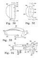
- the top surface 524 of the tibial tray 512 is non-planar. That is, as shown in FIGS. 38 and 39 , the top surface 524 may have a convex shape or otherwise be curved in an outward direction. Alternatively, as shown in FIGS. 40 and 41 , the top surface 524 may have a concave shape or otherwise be curved in an inward direction. The top surface 524 may be so curved in the generally anterior-posterior direction, in the generally medial-lateral direction, or in both the generally anterior-posterior direction and the generally medial-lateral direction. As discussed below, the top surface 524 of the tibial tray 512 is configured to contact or otherwise be positioned adjacent to a bottom surface 576 of the tibial insert 514.
- the bottom surface 526 of the base 518 of the tibial tray 512 is non-planar. That is, as with the bottom surface 26, the bottom surface 526 may be defined by an anterior planar surface 544 positioned toward the anterior side 538 of the tibial tray 512 and a posterior planar surface 546 positioned toward the posterior side 40 of the tibial tray 12.
- the posterior surface 546 is oblique to the anterior planar surface 544 so as to form an oblique angle between them similar to the surfaces 44, 48 described above in regard to FIG. 2 .
- the bottom surface 526 may be defined by more than two oblique planar surfaces.
- the bottom surface 526 may be defined by any number of oblique planar surfaces.
- the bottom surface 526 may include an additional planar surface (not shown) extending from the anterior end of the planar surface 544 so as to define an oblique angle between them.
- the tibial tray 512 includes an elongated recess 560 defined longitudinally in the base 518 in a generally anterior-posterior direction. As described below, the recess 560 is configured to receive a stem 572 of the tibial insert 514.
- the illustrative recess 560 has an oblong shape, but recesses having other configurations may be used in other embodiments.
- the tibial insert 514 includes a base 570 and a stem 572 extending downwardly therefrom.
- the base 570 has an upper bearing surface 574 and a bottom surface 576.
- the upper bearing surface 574 of the tibial insert 514 is configured to engage a natural or prosthetic femoral condyle of a patient's femur. During use, the patient's femur or femoral component articulates on the upper bearing surface 574.
- the bottom surface 576 is configured to contact or otherwise be positioned adjacent to the top surface 524 of the tibial tray 512 when coupled together as illustrated in FIGS. 39 and 41 .
- the bottom surface 576 may be planar or non-planar (e.g., convex or concave) based upon the curvature of the top surface 524 such that the bottom surface 576 is configured to mate with the top surface 524 during use.
- the bottom surface 576 of the tibial insert 514 is concave and is configured to contact or otherwise mate with the convex top surface 524 of the tibial insert 14 as shown in FIG. 39 .
- the bottom surface 576 of the tibial insert 514 is convex is configured to contact or otherwise mate with the concave top surface 524 of the tibial insert 514 as shown in FIG. 41 .
- the stem 572 is configured to be received in the recess 560 of the tibial tray 415 and, as such, may have any configuration such that stem 572 may be received therein.
- the stem 572 has an extended dome shape formed by an outer surface 578.
- the outer surface 578 is configured to contact or otherwise be positioned adjacent to an inner wall 580 that defines the recess 60 when the tibial insert 514 and the tibial tray 512 are coupled together.
- the tibial insert 514 may be coupled to the tibial tray 512 by positioning the tibial insert 514 on the tibial tray 512 such that the stem 572 of the insert 514 is received in the recess 560 of the tray 512 as shown in FIGS. 39 and 41 .
- the bottom surface 576 of the stem 572 contacts or is otherwise adjacent to the top surface 524 of the tibial tray 512.
- the outer surface 578 of the stem 572 contacts or is otherwise positioned adjacent the inner wall 580 of the recess when the tibial insert 514 is coupled to the tibial tray 512.
- the stem 572 may be configured to move within the recess 560 in one or more directions.
- the tibial insert 514 may be configured to move some amount relative to the tibial tray 512 in the generally anterior-posterior direction, the generally medial-lateral direction, or a combination of both directions.
- a fixed tibial assembly may include a tibial insert having a non-planar or otherwise curved bottom surface configured to contact a non-planar or curved upper surface of the tibial tray when coupled thereto.
- the bottom surface of the tibial insert may be concave or convex and the upper surface of the tibial tray may be convex or concave, respectively,
- the fixed tibial assembly may include a tibial tray having a non-planar or otherwise curved bottom surface.
Abstract
Description
- The present invention relates generally to orthopaedic prostheses, and particularly to tibial assemblies including a tibial tray and a tibial insert.
- During the lifetime of a patient, it may be necessary to perform a joint replacement procedure on the patient as a result of, for example, disease or trauma. For example, many knee replacement surgeries are performed each year. Total knee replacement or arthroplasty may involve replacement of the mid-shaft portion of the femur, proximal, distal, and/or total femur, and proximal tibia. Unicompartmental knee replacement or arthroplasty involves unicondylar resurfacing. Unicompartmental knee arthroplasty provides an alternative to total knee arthroplasty for rehabilitating knees when only one condyle has been damaged as a result of trauma or disease such as noninflammatory degenerate joint disease or its composite diagnosis of osteoarthritis or post-traumatic arthritis. As such, unicompartmental knee arthroplasty may be indicated for use in patients undergoing surgery for a severely painful and/or disabled joint damaged as a result of osteoarthritis, traumatic arthritis, rheumatoid arthritis, or a failed previous implant when only one condyle of the knee (medial or lateral) is affected. Further, unicompartmental knee replacements may be "multi-piece" replacements in which a unicompartmental tibial insert is used to replace each of the medial and lateral condyles of the patient. A single, total femoral component or two partial femoral components may be used to cooperate with the two unicompartmental inserts.
- In addition, in some knee replacement procedures, a total knee tibial tray may used with a unicompartmental tibial insert. For example, a total knee tibial tray may be used with a single unicompartmental tibial insert to replace either the medial or lateral condyle of the patient's knee. Alternatively, a total knee tibial tray may be used with two unicompartmental tibial inserts, each replacing one of the medial and lateral condyles of the patient's knee. In such applications, the medial and lateral unicompartmental tibial inserts may have different characteristics and be selected based on the orthopaedic considerations associated with the respective condyle of the patient's knee.
- Unicompartmental knee replacements are intended to provide increased patient mobility and reduce pain by replacing the damaged knee joint articulation in patients where there is evidence of sufficient sound bone to seat and support the components. Age and activity level factor into all reconstructive procedures and the state of the arthritis determines the treatment. With the advancement of minimally invasive techniques that support unicompartmental knee reconstruction, a growing number of patients are offered this alternative for relief from the disabling pain of arthritis and for the potential benefits of a rapid recovery.
- A tibial assembly of a unicompartmental knee prosthesis typically includes a tibial tray configured to be coupled to the patient's tibia and a polymer tibial bearing or insert adjacent the tibial tray. As discussed above, the tibial tray may be a total or unicompartmental tibial tray. The tibial insert includes an upper bearing surface configured to engage a corresponding articulating condylar surface of a femoral component coupled to the patient's femur. A mobile tibial assembly generally refers to a tibial assembly wherein the tibial insert is movable relative to the tibial tray. In other words, the tibial insert may rotate relative to the tray and/or the tibial insert may move medially, laterally, anteriorly, and/or posteriorly relative to the tibial tray. This motion of the tibial insert relative to the tray may be constrained in any number of ways in order to limit the type of motion of the tibial insert. For example, the tibial insert may be limited to anterior/posterior motion relative to the tibial tray and/or rotation of the tibial insert relative to the tibial tray may be limited to something less than 360° rotation. A fixed tibial assembly generally refers to a tibial assembly wherein the tibial insert is not movable relative to the tibial tray and remains in a fixed location thereon. Surgeons may choose between fixed and mobile tibial assemblies depending upon the particular needs of the patient.
- Typical mobile tibial assemblies fall into one of two classifications with respect to the insert-to-tray interface: unconstrained and constrained. In an unconstrained mobile tibial assembly, the tibial insert is free to move in all directions relative to the tibial tray. In a constrained mobile tibial assembly, the tibial insert is typically restricted from movement relative to the tibial tray in all but one or more directions and/or movements (e.g., translations and/or rotations).
- In one aspect, the invention provides a unicompartmental mobile tibial assembly which includes a tibial tray and a tibial insert. The tibial tray may be configured to be coupled to a surgically-prepared surface of the proximal end of a tibia. The tibial tray may include an upper surface and a bottom surface. The bottom surface of the tibial tray may be configured to engage a portion of the surgically-prepared surface of the tibia when coupled thereto. The tibial insert may be configured to be coupled to the tibial tray. The tibial insert may include an upper bearing surface and a bottom bearing surface. The upper bearing surface of the tibial insert may be configured to engage a surgically-prepared surface of the distal end of a femur. The bottom bearing surface of the tibial insert may be configured to engage the upper surface of the tibial tray when the tibial insert is coupled to the tibial tray. The tibial insert may be movable relative to the tibial tray. Any one or more of the upper surface of the tibial tray, the bottom surface of the tibial tray, and/or the bottom surface of the tibial insert may be non-planar.
- In some embodiments, the bottom surface of the tibial tray may include a first planar surface portion and a second planar surface portion. The first planar surface portion is oblique relative to the second planar surface portion. Additionally, in some embodiments, the bottom surface of the tibial tray may include a third planar surface portion. The third planar surface portion may be oblique to the second planar surface portion and/or the first planar surface portion.
- As discussed above, the upper surface of the tibial tray may be non-planar in some embodiments. For example, the upper surface of the tibial tray may be convex or concave. In some embodiments, the upper surface of the tibial tray may be both longitudinally and latitudinally convex. Additionally or alternatively, as discussed above, the upper surface of the tibial tray may be non-planar in some embodiments. For example, the upper surface of the tibial tray may be concave or convex.
- In some embodiments, the upper surface of the tibial tray may be convex and the bottom bearing surface of the tibial insert may be concave such that the convex upper surface of the tibial tray engages the concave bottom bearing surface of the tibial insert as the tibial insert is moved relative to the tibial tray. Alternatively, the upper surface of the tibial tray may be concave and the bottom bearing surface of the tibial insert may be convex such that the concave upper surface of the tibial tray engages the convex bottom bearing surface of the tibial insert as the tibial insert is moved relative to the tibial tray.
- In some embodiments, the tibial tray may include a track defined in the upper surface. The track may include a non-planar bottom wall. For example, the bottom wall of the track may be latitudinally concave, longitudinally concave, or latitudinally and longitudinally concave. Additionally, in some embodiments, the tibial insert may include a stem. The stem may extend downwardly from the bottom bearing surface of the tibial insert. The stem may be configured to be received by the track of the tibial tray. In some embodiments, the stem may include a non-planar bottom wall configured to engage the non-planar bottom wall of the track when the stem is received by the track. For example, the non-planar bottom wall of the stem is convex. The stem may have a substantially hemispherical shape, a. substantially spherical shape, an elliptical bottom profile when viewed in plan view, a circular bottom profile when viewed in plan view, and/or a polygonal bottom profile when viewed in plan view.
- In some embodiments, the track of the tibial tray may include a first side wall, a second side wall, a first protrusion extending from the first side wall a first distance over a portion of the non-planar bottom wall, and a second protrusion extending from the second wall a second distance over a portion of the non-planar bottom wall a second distance greater than the first distance. The first and the second protrusions may define an opening between them. In such embodiments, the stem of the tibial insert may include a flange defined at a distal end. The flange may have a bottom surface configured to engage the non-planar bottom wall of the track of the tibial tray when the stem is received thereby. The flange may also have a top surface configured to engage a bottom surface of at least one of the first protrusion and the second protrusion of the track of the tibial tray when the stem is received thereby. Additionally or alternatively, the flange may have a first distal end and a second distal end extending from a central axis of the stem, The second distal end may extend from the from the stem farther than the first distal end. The first protrusion of the track may be configured to engage a portion of the first distal end of the flange and the second protrusion of the track may be configured to engage a portion of the second distal end of the flange. In some embodiments, the first protrusion may extend from the first wall a first distance and the second protrusion extends from the second wall a second distance. The second distance being greater than the first distance.
- The assembly of the invention can be used in a method for implanting a unicompartmental tibial assembly which includes securing a tibial tray to a surgically-prepared surface of the proximal end of a tibia. The tibial tray having a non-planar upper surface. The method may also include engaging a non-planar bottom surface of a tibial insert to the non-planar upper surface of the tibial tray. Additionally, in some embodiments, the method may include resecting a portion of the tibia such that the surgically prepared surface of the tibia is non-planar. In such embodiments, the tibial tray may be secured by engaging a non-planar bottom surface of the tibial tray to the non-planar surgically prepared surface of the tibia.
- In another aspect, the invention provides a mobile tibial assembly which includes a tibial tray configured to be coupled to a surgically-prepared surface of the proximal end of a tibia and a tibial insert configured to rest on the tibial tray. The tibial tray may include a platform having an upper surface. The tibial tray may also include an anchor extending downwardly from a bottom surface of the platform and a channel formed in the upper surface of the platform. The channel of the tibial tray may be generally parallel to an inboard surface of the platform of the tibial tray and may extend from an anterior side of the platform to a posterior side of the platform. The tibial insert may include a platform and a stem. The stem may extend downwardly from the platform. The stem may also be received within the channel of the tibial tray. The stem may include a medial surface defining a curved line extending from the anterior side of the tibial insert to the posterior side of the tibial insert when viewed in a plan view. The tibial assembly may be a unicompartmental tibial assembly. In some embodiments, the stem of the tibial tray may include a body extending from the anterior side of the tibial insert to the posterior side of the tibial insert and a flange coupled to the body and also extending from the anterior side of the tibial insert to the posterior side of the tibial insert.
- In some embodiments, a top surface of the foot is spaced-apart from a bottom surface of the platform of the tibial insert to define a slot between them. The illustrative slot is curved when viewed in a plan view and extends from the anterior side of the tibial insert to the posterior side of the tibial insert. Additionally, the platform of the tibial tray may include a lip configured to define an undercut of the channel. The flange of the stem may be received within the undercut of the channel.
- The invention also provides a mobile tibial assembly which includes a tibial tray configured to be coupled to a surgically-prepared surface of the proximal end of a tibia. The assembly may also include a tibial insert configured to rest on the tibial tray. The tibial tray may include a platform having an upper surface. The tibial tray may also include an anchor extending downwardly from a bottom surface of the platform and a channel formed in the upper surface of the platform. The channel may be generally parallel to an inboard surface of the platform of the tibial tray and may extend from an anterior side of the platform to a posterior side of the platform. The tibial insert may include a platform and a stem. The stem may extend downwardly from the platform and be received within the channel of the tibial tray. The stem of the tibial insert may include a narrowed neck extending downwardly from the bottom surface of the platform of the tibial insert and a spherical body coupled to the narrowed neck and configured to be received within the channel. The channel of the tibial tray may be generally circular in shape when in viewed in cross-section.
- The invention also provides a mobile tibial assembly which includes a tibial tray configured to be coupled to a surgically-prepared surface of the proximal end of a tibia. The tibial tray may also include a tibial insert configured to rest on the tibial tray. The tibial tray may include a platform having an upper surface. The tibial tray may also include an anchor extending downwardly from a bottom surface of the platform and a channel formed in the upper surface of the platform. The channel of the tibial tray may be generally parallel to an inboard surface of the platform of the tibial tray and may extend from an anterior side of the platform to a posterior side of the platform. The tibial insert may include a platform and a stem. The stem may extend downwardly from the platform and be received within the channel of the tibial tray. In some embodiments, the stem of the tibial insert is dome-shaped.
- A number of different embodiments of tibial assemblies are described below. Illustratively, the tibial assemblies are illustrated and described as unicompartmental tibial assemblies intended to replace only one of the two bearing surfaces of a patient's tibia. As such, the tibial assemblies may be used by an orthopaedic surgeon or other healthcare provider during the performance of a unicompartmental knee arthroplasty (UKA) procedure. However, it should be appreciated that the tibial assemblies described herein may also be used during the performance of a total knee arthroplasty (TKA) procedure. For example, a single tibial assembly may be used for each bearing surface of the tibia thereby improving the overall customizability of the orthopaedic implant compared to typical total knee arthroplasty implants. Additionally, the tibial assemblies described herein may be used by the surgeon or other healthcare provider during the performance of an orthopaedic surgical procedure using either conventional or minimally invasive surgical methods. Further, although the features of the tibial assemblies are described in reference to an orthopaedic knee implant, it should be appreciated that such features are applicable to other types of orthopaedic implants including, but not limited to, hip implants, shoulder implants, elbow implants, spine implants, finger implants, toe implants, wrist implants, and ankle implants.
- Embodiments of the invention are described below by way of example with reference to the accompanying drawings, in which:
-
FIG. 1 is an exploded perspective view of an embodiment of a unicompartmental tibial assembly; -
FIG. 2 is an exploded side elevation view of the unicompartmental tibial assembly ofFIG. 1 ; -
FIG. 3 is an exploded side elevation view of another embodiment of the unicompartmental tibial assembly ofFIG. 1 ; -
FIG. 4 is a bottom perspective view of one embodiment of a tibial insert of the unicompartmental tibial assembly ofFIG. 1 ; -
FIG. 5 is a perspective view of the unicompartmental tibial assembly ofFIG. 1 in an assembled configuration; -
FIG. 6 is a cross-sectional view of the unicompartmental tibial assembly ofFIG. 4 taken generally along the section lines 6-6; -
FIG. 7 is an exploded perspective view of another embodiment of a unicompartmental tibial assembly; -
FIG. 8 is an exploded side elevation view of the unicompartmental tibial assembly ofFIG. 7 ; -
FIG. 9 is a bottom perspective view of one embodiment of a tibial insert of the unicompartmental tibial assembly ofFIG. 7 ; -
FIG. 10 is a bottom perspective view of another embodiment of the tibial insert of the unicompartmental tibial assembly ofFIG. 7 ; -
FIG. 11 is a perspective view of the unicompartmental tibial assembly ofFIG. 7 in an assembled configuration; -
FIG. 12 is a cross-sectional view of the unicompartmental tibial assembly ofFIG. 11 taken generally along the section lines 12-12; -
FIG. 13 is an exploded perspective view of another embodiment of a unicompartmental tibial assembly; -
FIG. 14 is an exploded side elevation view of the unicompartmental tibial assembly ofFIG. 13 ; -
FIG. 15 is a bottom perspective view of one embodiment of a tibial insert of the unicompartmental tibial assembly ofFIG. 13 ; -
FIG. 16 is a perspective view of the unicompartmental tibial assembly ofFIG. 13 in an assembled configuration; -
FIG. 17 is a cross-sectional view of the unicompartmental tibial assembly ofFIG. 16 taken generally along the section lines 17-17; -
FIG. 18 is an exploded perspective view of another embodiment of the unicompartmental tibial assembly; -
FIG. 19 is an exploded side elevation view of the unicompartmental tibial assembly ofFIG. 18 ; -
FIG. 20 is a bottom perspective view of one embodiment of the tibial insert of the unicompartmental tibial assembly ofFIG. 18 ; -
FIG. 21 is a perspective view of the unicompartmental tibial assembly ofFIG. 18 in an assembled configuration; -
FIG. 22 is a cross-sectional view of the unicompartmental tibial assembly ofFIG. 21 taken generally along the section lines 22-22; -
FIG. 23 is an exploded perspective view of another embodiment of a unicompartmental tibial assembly; -
FIG. 24 is an exploded side elevation view of the unicompartmental tibial assembly ofFIG. 23 ; -
FIG. 25 is an exploded end elevation view of the unicompartmental tibial assembly ofFIG. 23 ; -
FIG. 26 is a side elevation view of a tibial insert of the unicompartmental tibial assembly ofFIG. 23 ; -
FIG. 27 is a perspective view of the unicompartmental tibial assembly ofFIG. 23 in an assembled configuration; -
FIG. 28 is a cross-sectional view of the unicompartmental tibial assembly ofFIG. 27 taken generally along the section lines 28-28; -
FIG. 29 is an exploded perspective view of another embodiment of a unicompartmental tibial assembly; -
FIG. 30 is a top plan view of one embodiment of a tibial tray of the tibial assembly ofFIG. 29 ; -
FIG. 31 is an end view of the tibial tray ofFIG. 30 ; -
FIG. 32 is a bottom plan view of one embodiment of the tibia insert of the tibial assembly ofFIG. 30 ; -
FIG. 34 is an end view of the tibial insert ofFIG. 32 ; -
FIG. 34 is a top view of the tibial assembly ofFIG. 30 in an assembled configuration having the tibial insert in an initial position relative to the tibial tray; -
FIG. 35 is a top view of the tibial assembly ofFIG. 30 in an assembled configuration having the tibial insert in another position relative to the tibial tray; -
FIG. 36 is an exploded perspective view of another embodiment of a unicompartmental tibial assembly; -
FIG. 37 is an exploded perspective view of another embodiment of a unicompartmental tibial assembly; -
FIG. 38 is an exploded perspective view of another embodiment of the unicompartmental tibial assembly; -
FIG. 39 is a perspective view of the unicompartmental tibial assembly ofFIG. 38 in an assembled configuration; -
FIG. 40 is an exploded perspective view of another embodiment of the unicompartmental tibial assembly; and -
FIG. 41 is a perspective view of the unicompartmental tibial assembly ofFIG. 40 in an assembled configuration. - Referring now to the drawings,
FIGS. 1 to 6 show atibial assembly 10 which includes atibial tray 12 and a bearing, herein referred to astibial insert 14. Thetibial insert 14 is formed from a polymer material, but may be formed from other materials, such as a ceramic material, a metallic material, a bio-engineered material ,or the like, in other embodiments. Similarly, thetibial tray 12 is formed from a metallic material, but may be formed from other materials, such as a ceramic material, a polymer material, a bio-engineered material ,or the like, in other embodiments. - The
tibial tray 12 is configured to be coupled to a surgically-prepared surface of the proximal end of a patient'stibia 16 as illustrated inFIG. 2 . Thetibial tray 12 includes abase 22 and a number ofanchoring devices 20, commonly referred to as stems or keels, extending downwardly therefrom. When thetibial tray 12 is coupled to the patient'stibia 16, theanchoring devices 20 are embedded in the patient'stibia 16 to thereby secure thetibial tray 12 to the patient's bone. - The
base 22 has a generally "D"-shaped top profile and includes anupper surface 24 and abottom surface 26 from which theanchoring devices 20 extend. Thebase 22 has a generally straightouter surface 28 defining aninboard side 30 of thetibial tray 12, a generally curvedouter surface 32 defining anoutboard side 34 of thetibial tray 12, anend surface 36 defining ananterior side 38 of thetibial tray 12, and anend surface 40 defining aposterior side 42 of thetibial tray 12. It should be appreciated that theillustrative tibial assembly 10 is but one embodiment of a tibial assembly and that the features and components of thetibial assembly 10 may be used with a tibial assembly configured to replace the medial and/or lateral condyle of a patient's right tibia, as well as, the medial and/or lateral condyle of the patient's left tibia. - In the embodiment shown in the drawings, the
upper surface 24 of thetibial tray 12 is non-planar. That is, theupper surface 24 has a convex shape or is otherwise curved. Theupper surface 24 may be curved in a generally anterior-posterior direction, in a generally medial-lateral direction, or in both a generally anterior-posterior direction and a generally medial-lateral direction as is illustrated in the illustrative embodiment. As discussed below, theupper surface 24 of thetibial tray 12 is configured to contact or otherwise be positioned adjacent to abottom surface 70 of thetibial insert 14. - As shown in
FIG. 2 , thetibial tray 12 is configured to be coupled to a surgically-prepared surface of the proximal end of thetibia 16. To facilitate the coupling of thetibial tray 12 to thetibia 16, thebottom surface 26 of thetibial tray 12 is non-planar. For example, as illustrated inFIG. 2 , thebottom surface 26 may be defined by an anteriorplanar surface 44 positioned toward theanterior side 38 of thetibial tray 12 and a posteriorplanar surface 46 positioned toward theposterior side 42 of thetibial tray 12. The posteriorplanar surface 46 is oblique to the anteriorplanar surface 44 so as to form anangle 48 between them. The size of theangle 48 established between thesurfaces surface tibia 16. For example, as shown inFIG. 2 , the anteriorplanar surface 44 transfers force generated during patient use downwardly toward the centre of thetibia 16 as indicated via theforce vector arrow 50. Similarly, theposterior surface 46 transfers the force generated during patient use downwardly toward the center of thetibia 16 as indicated byforce vector arrow 52. In this way, the downward force of thetibial insert 14 generated during patient use is directed toward the center of thetibia 16 across substantially theentire bottom surface 26. - In some embodiments, the
bottom surface 26 may be defined by more than two oblique planar surfaces. That is, thebottom surface 26 may be defined by any number of oblique planar surfaces. For example, in some embodiments, thebottom surface 26 may include an additionalplanar surface 54 located near the anterior edge of thetibial tray 12 as shown in phantom inFIG. 2 . As with theplanar surfaces planar surface 54 and theplanar surface 44 define anangle 56 between them. Similar to theangle 48, the size of theangle 56 is selected such that the downward force generated during patient use is transferred by eachsurface tibia 16. For example, thesurface 54 transfers the force generated during patient use downwardly toward the center of thetibia 16 as indicated byforce vector arrow 58. - Either one or both of the
angles planar surface 44 andplanar surface 46 may not be straight in the medial-lateral direction. Similarly, the line defined by the intersection between theplanar surface 44 and theplanar surface 54 may not be straight in the medial-lateral direction. Rather any one or both of the defined intersection lines may be curved or otherwise angled in the medial-lateral direction. For example, one end of the line defined by the intersection of theplanar surface 44 andplanar surface 46 may be positioned more anteriorly than the opposite end or may be positioned more posteriorly than the opposite end. As such, the non-planar profile of thebottom surface 26 of thetibial tray 12 may be varied between theinboard side 30 and theoutboard side 34. - In other embodiments, the
bottom surface 26 of thetibial tray 12 may be concavely curved or planar. In such embodiments, the patient'stibia 16 may be resected using a single planar cut or, as illustrated inFIG. 3 , using a number of planar cuts, each cut being oblique to another. That is, thetibia 16 may be resected to have atop surface 80 configured to be coupled to thebottom surface 26 of thetibia tray 12 that is defined by a number ofplanar surfaces planar surfaces tibial tray 12 is coupled to the resectedtibia 16 using a suitable adhesive such as bone cement. Because the adhesive is "form fitting" to thetibial tray 12 and thetibia 16, any space formed between thebottom surface 26 of thetibial tray 12 and thetop surface 82 of thetibia 16 is substantially filled by the adhesive. Additionally, because the resectedsurface 80 of thetibia 16 is defined by a number of oblique,planar surfaces surface tibial tray 12 is transferred toward the center of thetibia 16 as indicated inFIG. 3 via theforce vector arrows tibial tray 12 during use toward the center of thetibia 16. For example, in some embodiments, thebottom surface 26 of thetibial tray 12 may be non-planar or otherwise curved and the resectedsurface 80 of thetibia 16 may be substantially planar. Alternatively, thebottom surface 26 of thetibial tray 12 may be substantially planar and the resectedsurface 80 of thetibia 16 may be non-planar or otherwise curved. Further, thebottom surface 26 of thetibial tray 12 may be non-planar or otherwise curved and the resectedsurface 80 of thetibia 16 may also be non-planar or otherwise curved. - Referring back to
FIG. 1 , thetibial tray 12 includes atrack 60 defined longitudinally in the base 22 in a generally anterior-posterior direction. As described below, thetrack 60 is configured to receive astem 68 of the tibial insert. Theillustrative track 60 is defined by a non-planar or otherwise curvedbottom surface 62. Thebottom surface 62 may be curved in the generally anterior-posterior direction, the generally medial-lateral direction, or in both the generally anterior-posterior direction and the generally medial-lateral direction. Theillustrative track 60 is convex in the generally anterior-posterior direction and concave in the generally medial-lateral direction. Although theillustrative track 60 is concave or curved, tracks having other shapes and configurations may be used in other embodiments as discussed below. - The
tibial insert 14 includes abase 66 and astem 68 extending downwardly therefrom. Thebase 66 has anupper bearing surface 69 and abottom surface 70. The upper bearing surface 69 of thetibial insert 14 is configured to engage a natural or prosthetic femoral condyle of a patient's femur. During use, the patient's femur or femoral component articulates on theupper bearing surface 69. Thebottom surface 70 is configured to contact or otherwise be positioned adjacent to theupper surface 24 of thetibial tray 12 when coupled together as illustrated inFIG. 5 . As such, thebottom surface 70 may be planar or non-planar (e.g., convex or concave) based upon the curvature of theupper surface 24 such that thebottom surface 70 is able to mate with theupper surface 24 during use. In the illustrative embodiment ofFIGS. 1-6 , thebottom surface 70 of thetibial insert 14 is concave as illustrated inFIG. 4 and is configured to contact or otherwise mate with the convexupper surface 24 of thetibial insert 14. - In the illustrative embodiment, the
stem 68 is embodied as abearing 72 extending downwardly from thecurved bottom surface 70. Thebearing 72 is configured to be received in thetrack 60 of the tibial tray and, as such, may have any configuration such that bearing 72 may be received therein. In the illustrative embodiment ofFIGS. 1-6 , thebearing 72 has a substantially convex shape. That is, thebearing 72 has a substantially hemi-spherical or otherwise spherical cap shape. As such, thebearing 72 has a curvedouter surface 74 that is configured to contact or otherwise be positioned adjacent to the track'scurved bottom surface 62 when thetibial insert 14 and thetibial tray 12 are coupled together. - During the performance of the orthopaedic surgical procedure (e.g., a UKA or TKA procedure), the
tibial insert 14 may be coupled to thetibial tray 12 by positioning thetibial insert 14 on thetibial tray 12 such that the bearing 72 of theinsert 14 is received in thetrack 60 of thetray 12 as shown inFIGS. 5 and6 . When thetibial insert 14 is coupled to thetibial tray 12, thebottom surface 70 of thetibial insert 14 contacts or is otherwise adjacent to theupper surface 24 of thetibial tray 12. Because thebottom surface 70 of thetibial 12 is concave and theupper surface 24 of thetibial tray 12 is convex, thesurfaces tibial insert 14 to be moved relative to thetibial tray 12. In addition, theouter surface 74 of the bearing 72 contacts or is otherwise positioned adjacent the track'sbottom surface 62 when thetibial insert 14 is coupled to thetibial tray 12. Again, because theouter surface 74 is convex and thebottom surface 62 is concave, thesurfaces tibial insert 14 to be moved relative to thetibial tray 12. - During patient use, the
tibial insert 14 moves back and forth along thetrack 60 of thetibial tray 12 in a generally anterior-posterior direction. In embodiments wherein thebottom surface 26 of thetibial tray 12 is non-planar, the force exerted on the tibial tray is directed toward the center of the patient's tibia as discussed above. In addition, because thetop surface 24 of thetibial tray 12 is non-planar, the force exerted on the tibial tray is further directed toward the center of the patient's tibia astibial insert 14 moves across thetop surface 24. Yet further, because theposterior side 42 of thetibial tray 12 is in a more inferior position than theanterior side 38 of thetibial tray 12 when coupled to the patient'stibia 16, the patient'stibia 16 moves in a downwardly direction when the patient's knee is in flexion relative to the extension position of the tibia. As such, the laxity of the knee joint is increased, which may increase the range of motion of the patient's knee. Further, because thebearing 72 is hemi-spherical or spherical cap in shape, thetibial insert 14 may be configured to rotate about a center axis defined by thebearing 72. As such, in use, thetibial insert 14 is configured to rotate while, or in addition to, moving anteriorly or posteriorly within thetrack 60. - Referring now to
FIGS. 7-12 , in another embodiment, thetribal tray 12 may includetrack 100 in place of thetrack 60. Thetrack 100 is defined by abottom wall 102 andside walls side walls bottom surface 102 in a substantially orthogonal orientation such that thetrack 100 defined thereby has a rectangular cross-section. As with thetrack 60, thebottom wall 102 may be non-planar or otherwise curved. In the illustrative embodiment, thebottom wall 102 is convex in the generally anterior-posterior direction and substantially planar or flat in the generally medial-lateral direction. - In embodiments in which the
tibial tray 12 includes thetrack 100, thetibial insert 14 includes astem 110 in place of thestem 68. Thestem 110 has a hexagonal shape when viewed in the bottom plan view. Thestem 110 includes abottom surface 112 and sixside surfaces 114 that cooperate to define the hexagonal shape as shown inFIG. 9 . Although theillustrative stem 110 is hexagonal in shape, it should be appreciated that stems having other shapes may be used in other embodiments. Thestem 110 is configured to be received by thetrack 100. As such, thebottom surface 112 of thestem 110 is substantially planar such that thebottom surface 112 is configured to contact or otherwise mate with the track's medially-laterally planarbottom wall 102. However, as illustrated inFIG. 10 , in embodiments in which the track'sbottom wall 102 is curved or otherwise non-planar, thestem 110 may include abottom surface 116 that is also non-planar. For example, in embodiments wherein the track'sbottom wall 102 is concave in the generally medial-lateral direction similar to thetrack 60 illustrated in and discussed above in regard toFIGS. 1-6 , thebottom surface 116 may be convex such that thebottom surface 116 is able to contact or mate with thebottom wall 102. - During the performance of the orthopaedic surgical procedure (e.g., a UKA or TKA procedure), the
tibial insert 14 may be coupled to thetibial tray 12 by positioning thetibial insert 14 on thetibial tray 12 such that thestem 110 of theinsert 14 is received in thetrack 100 of thetray 12 as shown inFIGS. 11 and12 . As described above in regard to the embodiment ofFIGS. 1-6 , when thetibial insert 14 is coupled to thetibial tray 12, thebottom surface 70 of thetibial insert 14 contacts or is otherwise adjacent to theupper surface 24 of thetibial tray 12. Again, because thebottom surface 70 of thetibial insert 14 is concave and theupper surface 24 of thetibial tray 12 is convex, thesurfaces tibial insert 14 to be moved relative to the tibial tray. In addition, thebottom surface stem 110 contacts or is otherwise positioned adjacent the track'sbottom wall 102 when thetibial insert 14 is coupled to thetibial tray 12. Because thebottom surface 112 is substantially planar and the track'sbottom wall 102 is also substantially planar, thesurface 112 and thewall 102 mate and thereby allow thetibial insert 14 to be moved relative to thetibial tray 12. Further, when thetibial insert 14 is coupled to thetibial tray 12, a parallel pair of theside walls 114 contact or are otherwise positioned adjacent theside walls side walls sidewalls 114 are straight, thetibial tray 12 is prevented from rotating about thestem 112. However, because thestem 110 is hexagonal in shape, thetibial insert 14 may be coupled to the tray in one of six different configurations. - During patient use, the
tibial insert 14 moves back and forth along thetrack 100 of thetibial tray 12 in a generally anterior-posterior direction. In addition, although the tibial insert is restricted from rotating about thestem 110 by the track'sside walls sidewalls 114, thetibial insert 14 may be positioned in any one of six different configurations relative to the tibial tray such that the positioning of any asymmetrical features of thetibial insert 14 may be customized to the particular patient. - Referring now to
FIGS. 13-17 , in another embodiment, thetribal tray 12 may include atrack 200 in place of thetrack 60. Thetrack 200 is defined by abottom wall 202 andside walls inboard lip 208 extends from theside wall 204 over a portion of thebottom wall 202. Similarly, anoutboard lip 210 extends from theside wall 206 over a portion of thebottom wall 202. Thelips elongated opening 212 in theupper surface 24 of thetibial tray 12. In the illustrative embodiment, thelips side walls lips side walls inboard lip 208 includes abottom surface 214 and theoutboard lip 210 includes abottom surface 216. In the illustrative embodiment, the bottom surfaces 214, 216 are oblique or otherwise non-parallel to the track'sbottom wall 202. However, in other embodiments, the bottom surfaces 214, 216 may be substantially parallel to the track'sbottom wall 202. - As with the
track 60, thebottom wall 202 of thetrack 200 may be planar or non-planar. In the illustrative embodiment, thebottom wall 202 of the track is substantially planar or flat in the generally medial-lateral direction, but convex in the generally anterior-posterior direction similar to thebottom wall 102 of thetrack 100 illustrated in and described above in regard toFIGS. 7-12 . - In embodiments in which the
tibial tray 12 includes thetrack 200, thetibial insert 14 includes astem 220 in place of thestem 68. Thestem 220 includes aflange 222 and aneck 224 connecting theflange 222 to thebottom surface 70 of thebase 66 of thetibial insert 14. As shown inFIGS. 13 and14 , theflange 222 has a width ordiameter 230 that is slightly less thanwidth 232 of the track'sbottom wall 202. Similarly, theneck 224 has awidth 234 that is slightly less than thewidth 236 of theelongated opening 212 defined between thelips stem 220 is received by thetrack 200, thetibial insert 14 may be moved along thetrack 200. However, because thewidth 230 of theflange 222 is greater than thewidth 236 of theelongated opening 212, thetibial insert 14 is retained in thetrack 200 via thelips tibial insert 14 from lifting off thetibial tray 12. - As shown in
FIG. 15 , theflange 222 has a generally elliptical or circular bottom profile, but may have other configurations in other embodiments. Theflange 220 includes atop surface 226 and abottom surface 228. In the embodiment illustrated inFIGS. 14-17 , thetop surface 226 is oblique or otherwise non-parallel to thebottom surface 228 such that theflange 220 may be received in thetrack 200. Additionally, thetop surface 226 is oblique or otherwise not parallel to the track'sbottom surface 202 whentibial insert 14 is received therein. However, in embodiments wherein thelips bottom surface 202, thetop surface 226 of theflange 222 may be parallel to thebottom surface 228 of theflange 222 and/or to the track'sbottom surface 202 such that theflange 222 may be received in thetrack 200. - During the performance of the orthopaedic surgical procedure (e.g., a UKA or TKA procedure), the
tibial insert 14 may be coupled to thetibial tray 12 by positioning thetibial insert 14 on thetibial tray 12 such that thestem 220 of theinsert 14 is received in thetrack 200 of thetray 12 as shown inFIGS. 16 and17 . As described above in regard to the embodiment ofFIGS. 1-6 , when thetibial insert 14 is coupled to thetibial tray 12, thebottom surface 70 of thetibial insert 14 contacts or is otherwise adjacent to theupper surface 24 of thetibial tray 12. Again, because thebottom surface 70 of thetibial insert 14 is concave and theupper surface 24 of thetibial tray 12 is convex, thesurfaces tibial insert 14 to be moved relative to thetibial tray 12. In addition, thebottom surface 228 of theflange 222 contacts or is otherwise positioned adjacent the track'sbottom wall 202 when thetibial insert 14 is coupled to thetibial tray 12. Because thebottom surface 228 is substantially planar and the track'sbottom wall 202 is also substantially planar, thesurface 228 and thewall 202 mate and thereby allow thetibial insert 14 to be moved relative to thetibial tray 12. Additionally, when thetibial insert 14 is coupled to thetibial tray 12, thetop surface 226 of theflange 222 contacts or is otherwise positioned adjacent the bottom surfaces 214, 216 of thelips stem 220 is received by thetrack 200, thetibial insert 14 is movable relative to thetibial tray 12 along thetrack 200, but is retained therein by thelips - During patient use, the
tibial insert 14 moves along thetrack 200 of thetibial tray 12 in the generally anterior-posterior direction. In addition, because theflange 222 has a substantially circular shape, thetibial insert 14 may be rotated about a central axis defined by thestem 220. As such, in use, thetibial insert 14 is configured to move in generally anteriorly-posteriorly and/or rotationally with respect to thetibial tray 12. - Referring now to
FIGS. 18-22 , in another embodiment, thetribal tray 12 may includetrack 300 in place of thetrack 60. Thetrack 300 has a substantially circular cross-section profile defined by aside wall 302. That is, theside wall 302 is curved or concave in the generally medial-lateral direction. As such, theside wall 302 curves inwardly toward theupper surface 24 of thetibial tray 12 so as to define anelongated opening 304 on theupper surface 24. In addition, theside wall 302 may be curved or otherwise non-planar in the generally anterior-posterior direction. For example, in the illustrative embodiment ofFIGS. 18-22 , theside wall 302 has a convex shape in the generally anterior-posterior direction. - In embodiments in which the
tibial tray 12 includes thetrack 300, thetibial insert 14 includes astem 310 in place of thestem 68. Thestem 310 includes aflange 314 and aneck 312 connecting theflange 314 to thebottom surface 70 of thebase 66 of thetibial insert 14. As shown inFIG. 20 , theflange 314 has a generally spherical shape defined by a curvedouter surface 315. Additionally, as shown inFIGS. 18 and19 , theflange 222 has a width or diameter 316 that is slightly less than thediameter 318 of thetack 300 as defined by theside wall 302. Similarly, theneck 312 has awidth 320 that is slightly less than thewidth 322 of theelongated opening 304 defined in theupper surface 24. As such, when thestem 310 is received by thetrack 300, thetibial insert 14 may be moved along thetrack 300. However, because the diameter 316 of theflange 314 is greater than thewidth 322 of theelongated opening 304, thetibial insert 14 is retained in thetrack 300 via the ends of theside wall 302 thereby preventing thetibial insert 14 from lifting off thetibial tray 12. - During the performance of the orthopaedic surgical procedure (e.g., a UKA or TKA procedure), the
tibial insert 14 may be coupled to thetibial tray 12 by positioning thetibial insert 14 on thetibial tray 12 such that thestem 310 of theinsert 14 is received in thetrack 300 of thetray 12 as shown inFIGS. 21 and22 . As described above in regard to the embodiment ofFIGS. 1-6 , when thetibial insert 14 is coupled to thetibial tray 12, thebottom surface 70 of thetibial insert 14 contacts or is otherwise adjacent to theupper surface 24 of thetibial tray 12. Again, because thebottom surface 70 of thetibial insert 14 is concave and theupper surface 24 of thetibial tray 12 is convex, thesurfaces tibial insert 14 to be moved relative to thetibial tray 12. In addition, the curvedouter surface 315 of theflange 314 contacts or is otherwise positioned adjacent to the track'scurved side wall 302. Once thestem 310 is received by thetrack 300, thetibial insert 14 is movable relative to thetibial tray 12 along thetrack 14, but is retained therein by the inwardly curving ends of thesidewall 302. - During patient use, the
tibial insert 14 moves along thetrack 300 of thetibial tray 12 in the generally anterior-posterior direction. In addition, because theflange 314 has a substantially spherical shape, thetibial insert 14 may be rotated about a central axis defined by thestem 310. As such, in use, thetibial insert 14 is configured to move anteriorly-posteriorly and/or rotationally with respect to thetibial tray 12. - Referring now to
FIGS. 23-28 , in another embodiment, thetribal tray 12 may includetrack 400 in place of thetrack 60. Thetrack 400 is defined by abottom wall 402 andside walls inboard lip 408 extends from theside wall 404 over a portion of thebottom wall 402. Similarly, anoutboard lip 410 extends from theside wall 406 over a portion of thebottom wall 402. Thelips elongated opening 412 in theupper surface 24 of thetibial tray 12. In the illustrative embodiment, theoutboard lip 410 extends from the side wall 406 a distance greater than theinboard lip 408. However, in other embodiments, thelips side walls inboard lip 408 includes abottom surface 413 and theoutboard lip 410 includes abottom surface 415. In the illustrative embodiment, the bottom surfaces 413, 415 are oblique or otherwise non-parallel to the track'sbottom wall 402. However, in other embodiments, the bottom surfaces 413, 415 may be substantially parallel to the track'sbottom wall 402. - As with the
track 60, thebottom wall 402 of thetrack 400 may be planar or non-planar. In the illustrative embodiment, thebottom wall 402 of the track is substantially planar or flat in the generally medial-lateral direction, but convex in the generally anterior-posterior direction similar to thebottom wall 102 of thetrack 100 illustrated in and described above in regard toFIGS. 7-12 . - In embodiments in which the
tibial tray 12 includes thetrack 400, thetibial insert 14 may be embodied as anelongated tibial insert 414 as shown inFIG. 23 . Thetibia insert 414 includes anelongated base 416 and anelongated stem 420 extending downwardly therefrom. Thebase 416 has an elongatedupper bearing surface 417 and anelongated bottom surface 418. Similar to the bearingsurface 69 of thetibial insert 14 described above, theupper bearing surface 417 of thetibial insert 414 is configured to engage a natural or prosthetic femoral condyle of a patient's femur. During use, the patient's femur or femoral component articulates on theupper bearing surface 417. Similar to thebottom surface 70 described above, thebottom surface 418 is configured to contact or otherwise be positioned adjacent to theupper surface 24 of thetibial tray 12 when coupled together as illustrated inFIG. 26 . As such, thebottom surface 418 may be planar or non-planar (e.g., convex or concave) based upon the curvature of theupper surface 24 such that thebottom surface 418 is able to mate with theupper surface 24 during use. In the illustrative embodiment ofFIGS. 23-28 , thebottom surface 418 of thetibial insert 414 is concave as illustrated inFIG. 26 and is configured to contact or otherwise mate with the convexupper surface 24 of thetibial insert 414. - The
stem 420 is configured to be received in thetrack 400 of thetibial tray 12. Thestem 420 includes aflange 422 and aneck 424 connecting theflange 422 to thebottom surface 418 of thebase 416 of theinsert 414. Theflange 422 has a generally rectangular bottom profile and includes aninboard end 426 and anoutboard end 428. As shown inFIG. 25 , theoutboard end 428 extends from the end of the neck 324 farther than theinboard end 426. That is, the shorterinboard end 426 of theflange 422 extends from a center of the neck 424 adistance 430 and theoutboard end 428 extends from the center of the neck 424 adistance 432, which is greater than thedistance 430. However, in other embodiments, theinboard end 426 may extend from theneck 424 farther than theoutboard end 428 or, alternatively, theends neck 424 the same or similar distance depending upon the configuration of thetrack 400. - As shown in
FIG. 25 , theflange 422 has a width ordiameter 434 that is slightly less thanwidth 436 of the track'sbottom wall 402. Similarly, theneck 424 has awidth 438 that is slightly less than thewidth 440 of theelongated opening 412 defined between thelips stem 420 is received by thetrack 400, thetibial insert 414 may be moved along thetrack 400. However, because thewidth 434 of theflange 422 is greater than thewidth 440 of theelongated opening 412, thetibial insert 414 is retained in thetrack 400 via thelips tibial insert 414 from lifting off thetibial tray 12. - The
flange 422 includes antop surface 442 and abottom surface 444. In the embodiment illustrated inFIGS. 23-28 , thetop surface 442 is oblique or otherwise not parallel to thebottom surface 444 such that theflange 422 may be received in thetrack 400. Additionally, thetop surface 442 is oblique or otherwise not parallel to the track'sbottom wall 402 whentibial insert 414 is received therein. However, in embodiments wherein thelips bottom surface 402, thetop surface 442 of theflange 422 may be parallel to thebottom surface 444 of theflange 422 and/or to the track'sbottom wall 402 such that theflange 422 may be received in thetrack 400. - During the performance of the orthopaedic surgical procedure (e.g., a UKA or TKA procedure), the
tibial insert 414 may be coupled to thetibial tray 12 by positioning thetibial insert 414 on thetibial tray 12 such that thestem 420 of theinsert 414 is received in thetrack 400 of thetray 12 as shown inFIGS. 27 and28 . When thetibial insert 414 is coupled to thetibial tray 12, thebottom surface 418 of thetibial insert 414 contacts or is otherwise adjacent to theupper surface 24 of thetibial tray 12. Because thebottom surface 418 of thetibial insert 414 is concave and theupper surface 24 of thetibial tray 12 is convex, thesurfaces tibial insert 414 to be moved relative to the tibial tray. In addition, thebottom surface 444 of theflange 422 contacts or is otherwise positioned adjacent the track'sbottom wall 402 when thetibial insert 414 is coupled to thetibial tray 12. Because thebottom surface 444 and the track'sbottom wall 402 are substantially planar in the generally medial-lateral direction and curved in the generally anterior-posterior direction, thewall 402 and thesurface 444 mate and thereby allow thetibial insert 414 to be moved relative to thetibial tray 12. Additionally, when thetibial insert 414 is coupled to thetibial tray 12, the shorterinboard end 426 of theflange 422 is received in the region defined under theinboard lip 408 and the longerlateral end 428 is received in the region defined under theoutboard lip 410. Once thestem 420 is received by thetrack 400, thetibial insert 414 is movable in the generally anterior-posterior direction relative to thetibial tray 12 along thetrack 400, but is retained therein by the lips 408,410. - Referring now to
FIGS. 29-35 , in another embodiment, thetibial assembly 10 includes atibial tray 512 and atibial insert 514. As described above in regard to the embodiment ofFIGS. 1-7 , thetibial insert 514 is illustratively formed from a polymer material, but may be formed from other materials, such as a ceramic material, a metallic material, a bio-engineered material ,or the like, in other embodiments. Similarly, thetibial tray 512 is illustratively formed from a metallic material, but may be formed from other materials, such as a ceramic material, a polymer material, a bio-engineered material, or the like, in other embodiments. - Similar to the
tibial tray 12, thetibial tray 512 is configured to be coupled to a surgically-prepared surface of the proximal end of a patient's tibia. Thetibial tray 512 includes abase 522 and a number of anchoringdevices 520, commonly referred to as stems or keels, extending downwardly therefrom. When thetibial tray 512 is coupled to the patient's tibia, the anchoringdevices 520 are embedded in the patient's tibia to thereby secure thetibial tray 512 to the patient's bone. - The
base 522 has a generally "D"-shaped top profile and includes anupper surface 524 and abottom surface 526 from which theanchoring devices 520 extend. Thebase 522 has a generally straightouter surface 528 defining aninboard side 530 of thetibial tray 512, a generally curvedouter surface 532 defining anoutboard side 534 of thetibial tray 512, anend surface 536 defining ananterior side 538 of thetibial tray 512, and anend surface 540 defining aposterior side 542 of thetibial tray 512. It should be appreciated that theillustrative tibial assembly 10 is but one embodiment of a tibial assembly and that the features and components of thetibial assembly 10 may be used with a tibial assembly configured to replace the medial and/or lateral condyle of a patient's right tibia, as well as, the medial and/or lateral condyle of the patient's left tibia. - In the illustrative embodiment, the
upper surface 524 and thebottom surface 526 of thetibial tray 512 are substantially planar. However, in other embodiments, any one or both of thesurfaces surfaces surfaces upper surface 524 of thetibial tray 512 is configured to contact or otherwise be positioned adjacent to abottom surface 570 of thetibial insert 514. - The
tibial tray 512 includes atrack 560 defined longitudinally in the base 522 in a generally anterior-posterior direction. As described below, thetrack 560 is configured to receive astem 516 of thetibial insert 514. Theillustrative track 560 is defined by a substantially planarbottom surface 562 andside walls side walls bottom surface 522 in a substantially orthogonal orientation such that thetrack 560 defined thereby has a rectangular cross-section. As shown inFIG. 30 , thetack 560 is offset toward theinboard side 530 of the base 522 such that theside wall 566 forms a portion of the generally straightouter surface 528. - An
outboard lip 568 extends from theside wall 204 over a portion of thebottom wall 564. Theoutboard lip 568 includes abottom surface 569. In the illustrative embodiment, thebottom surface 569 of theoutboard lip 568 is substantially parallel to thebottom surface 562. However, in other embodiments, the bottom surfaces 570 may be oblique to thebottom surface 562. Theoutboard lip 568 and theside wall 566 define anelongated opening 590 between them. - As with the
track 60, thebottom wall 564 of thetrack 560 may be planar or non-planar. In the illustrative embodiment, thebottom wall 560 is substantially planar or flat. However, in other embodiments, thebottom wall 560 may concavely or convexly curved in the generally medial-lateral direction and/or the anterior posterior direction. As illustrated inFIG. 30 , thetrack 560 is defined in theupper surface 524 of thetibial tray 512 in a generally anterior-posterior direction. However, in other embodiments, thetrack 560 may be defined in theupper surface 524 of thetibial tray 512 in a generally medial-lateral direction, or some combination of a generally anterior-posterior direction and a generally medial-lateral direction (i.e., a generally diagonal direction). Additionally, although theillustrative track 560 is substantially straight, thetibial tray 512 may include a track having other configurations in other embodiments. For example, a curved track may be used in some embodiments. - The
tibial insert 514 includes abase 566 and astem 516 extending downwardly therefrom. Thebase 566 has anupper bearing surface 569 and abottom surface 570. Theupper bearing surface 569 of thetibial insert 514 is configured to engage a natural or prosthetic femoral condyle of a patient's femur. During use, the patient's femur or femoral component articulates on theupper bearing surface 569. Thebottom surface 570 is configured to contact or otherwise be positioned adjacent to theupper surface 524 of thetibial tray 512 when coupled together. As such, thebottom surface 570 may be planar or non-planar (e.g., convex or concave) based upon the curvature of theupper surface 524 such that thebottom surface 570 is able to mate with theupper surface 524 during use. - The
stem 516 includes aflange 580 and aneck 582 connecting theflange 580 to thebottom surface 570 of thebase 566 of thetibial insert 514. As shown inFIG. 32 , theillustrative flange 580 has a substantially "D"-shaped bottom profile. That is, the center region of theflange 580 extends from theneck 582 farther than the ends of theflange 580. As illustrated inFIGS. 30 and 32 , the center region of theflange 580 defines amaximum width 574 of theflange 580, which is slightly less than thewidth 572 of the track'sbottom wall 564. Similarly, theneck 582 has a width has awidth 578 that is slightly less than thewidth 576 of theelongated opening 590 defined between thelip 568 and theside wall 566. As such, when thestem 516 is received by thetrack 560, thetibial insert 514 may be moved along thetrack 560. However, because themaximum width 574 of theflange 568 is greater than thewidth 576 of theelongated opening 590, thetibial insert 514 is retained in thetrack 560 via thelip 568 thereby preventing thetibial insert 514 from lifting off thetibial tray 512. - During the performance of the orthopaedic surgical procedure (e.g., a UKA or TKA procedure), the
tibial insert 514 may be coupled to thetibial tray 512 by positioning thetibial insert 514 on thetibial tray 512 such that thestem 516 of theinsert 514 is received in thetrack 560 of thetray 12 as shown inFIGS. 34 and 35 . As described above in regard to the embodiment ofFIGS. 1-6 , when thetibial insert 514 is coupled to thetibial tray 512, thebottom surface 570 of thetibial insert 514 contacts or is otherwise adjacent to theupper surface 524 of thetibial tray 512. Again, because thebottom surface 570 of thetibial insert 514 is concave and theupper surface 524 of thetibial tray 512 is convex, thesurfaces tibial insert 514 to be moved relative to thetibial tray 512. - During patient use, the
tibial insert 514 moves along thetrack 560 of thetibial tray 512 in the generally anterior-posterior direction. In addition, because theflange 568 is substantially "D"-shaped (i.e., the ends of theflange 568 extend from the neck a distance shorter than the center region of the flange 568), thetibial insert 514 may rotate within thetrack 560. That is, thetibial insert 514 may rotate within thetrack 560 such that acenter axis 592 of thetibial inset 514 is displaced from thecenter axis 594 of thetrack 560 as indicated inFIG. 35 viaarrow 596. Although only one direction of rotation is shown inFIG. 35 , it should be appreciated that thetibial insert 514 is configured to rotate in both directions during use. As such, in use, thetibial insert 514 is configured to move in a generally anterior-posterior direction within thetrack 560 and rotate some amount within thetrack 560. - Referring now to
FIG. 36 , in some embodiments, thetribal tray 12 may not include thetrack 60. Rather, theupper surface 24 of thetibial tray 12 may be substantially solid. However, similar to the embodiment described above in regard to the embodiment ofFIGS. 1-7 , theupper surface 24 of thetibia tray 12 is non-planar. That is, theupper surface 24 has a convex shape or is otherwise curved. Theupper surface 24 may be curved in a generally anterior-posterior direction, in a generally medial-lateral direction, or in both a generally anterior-posterior direction and a generally medial-lateral direction as is illustrated in the illustrative embodiment ofFIG. 36 . - In embodiments wherein the
tibial tray 12 does not include a track, thetibial insert 14 does not include a stem or bearing extending from thebottom surface 70 of theinsert 14. However, thebottom surface 70 of thetibial insert 14 is configured to contact or otherwise be positioned adjacent to thetop surface 24 of thetibial tray 12 when coupled. As such, similar to the embodiment described above in regard to the embodiment ofFIGS. 1 to 7 , thebottom surface 70 is also non-planar. That is thebottom surface 70 of thetibial insert 14 is concave such that thebottom surface 70 is configured to mate with theupper surface 24 of thetibial tray 12. - During the performance of the orthopaedic surgical procedure (e.g., a UKA or TKA procedure), the
tibial insert 14 may be coupled to thetibial tray 12 by positioning thetibial insert 14 on thetibial tray 12 such that thebottom surface 70 of thetibial insert 14 contacts or is otherwise adjacent to thetop surface 24 of thetray 12. Because thebottom surface 70 is concave and theupper surface 24 of thetibial tray 12 is convex, thesurfaces tibial insert 14 to be moved relative to thetibial tray 12. Because theinsert 14 does not include a stem, thetibial insert 14 is free to move in the anterior-posterior direction, the medial-lateral direction, as well as, rotationally. - Referring now to
FIG. 37 , in other embodiments, theupper surface 24 of thetibial tray 12 may be concave rather than convex as shown inFIG. 36 . The convexupper surface 24 is substantially solid and devoid of thetrack 60. In such embodiments, theupper surface 24 is configured to receive thebottom surface 70 of thetibial insert 14. Theupper surface 24 may be concavely curved in a generally anterior-posterior direction, in a generally medial-lateral direction, or in both a generally anterior-posterior direction and a generally medial-lateral direction as is illustrated in the illustrative embodiment ofFIG. 37 . - As described above, in embodiments wherein the
tibial tray 12 doe not include a track, thetibial insert 14 does not include a stem or bearing extending from thebottom surface 70 of theinsert 14. However, thebottom surface 70 of thetibial insert 14 is configured to contact or otherwise be positioned adjacent to thetop surface 24 of thetibial tray 12 when coupled. Again, similar to the embodiment described above in regard to the embodiment ofFIGS. 1-7 , thebottom surface 70 is also non-planar. In the illustrative embodiment ofFIG. 37 , thebottom surface 70 of thetibial insert 14 is convex such that thebottom surface 70 is configured to mate with the concaveupper surface 24 of thetibial tray 12. - During the performance of the orthopaedic surgical procedure (e.g., a UKA or TKA procedure), the
tibial insert 14 may be coupled to thetibial tray 12 by positioning thetibial insert 14 on thetibial tray 12 such that thebottom surface 70 of thetibial insert 14 contacts or is otherwise adjacent to thetop surface 24 of thetray 12. Because thebottom surface 70 is convex and theupper surface 24 of thetibial tray 12 is concave, thesurfaces tibial insert 14 to be moved relative to thetibial tray 12. As discussed above in regard toFIG. 36 , thetibial insert 14 is free to move in the anterior-posterior direction, the medial-lateral direction, as well as, rotationally. - Referring now to
FIGS. 38-41 in another embodiment, thetibial assembly 10 includes atibial tray 512 and a polymer bearing, herein referred to astibial insert 514. Similar to thetibial tray 12, thetibial tray 512 is configured to be coupled to a surgically-prepared surface of the proximal end of a patient's tibia (not shown). Thetibial tray 512 includes abase 518 and an anchoring stem orkeel 520 extending downwardly therefrom. When thetibial tray 512 is coupled to the patient's bone, thekeel 520 is embedded in the patient's tibia to thereby secure thetibial tray 512 to the patient's bone. - The
base 518 has a generally "D"-shaped top profile and includes anupper surface 524 and abottom surface 526 from which theanchoring keel 520 extends. Thebase 518 has a generally straightouter surface 528 defining aninboard side 530 of thetibial tray 512, a generally curvedouter surface 532 defining anoutboard side 534 of thetibial tray 512, anend surface 536 defining ananterior side 538 of thetibial tray 12, and anend surface 540 defining aposterior side 542 of thetibial tray 512. It should be appreciated that theillustrative tibial assembly 10 is but one embodiment of a tibial assembly and that the features and components of thetibial assembly 10 may be used with a tibial assembly configured to replace the medial and/or lateral condyle of a patient's right tibia, as well as, the medial and/or lateral condyle of the patient's left tibia. - In the illustrative embodiment, the
top surface 524 of thetibial tray 512 is non-planar. That is, as shown inFIGS. 38 and39 , thetop surface 524 may have a convex shape or otherwise be curved in an outward direction. Alternatively, as shown inFIGS. 40 and41 , thetop surface 524 may have a concave shape or otherwise be curved in an inward direction. Thetop surface 524 may be so curved in the generally anterior-posterior direction, in the generally medial-lateral direction, or in both the generally anterior-posterior direction and the generally medial-lateral direction. As discussed below, thetop surface 524 of thetibial tray 512 is configured to contact or otherwise be positioned adjacent to abottom surface 576 of thetibial insert 514. - Similar to the
bottom surface 26 of thetibial tray 12 discussed above in regard toFIGS. 1-6 , thebottom surface 526 of thebase 518 of thetibial tray 512 is non-planar. That is, as with thebottom surface 26, thebottom surface 526 may be defined by an anteriorplanar surface 544 positioned toward theanterior side 538 of thetibial tray 512 and a posteriorplanar surface 546 positioned toward theposterior side 40 of thetibial tray 12. Theposterior surface 546 is oblique to the anteriorplanar surface 544 so as to form an oblique angle between them similar to thesurfaces FIG. 2 . Additionally, in some embodiments, thebottom surface 526 may be defined by more than two oblique planar surfaces. That is, thebottom surface 526 may be defined by any number of oblique planar surfaces. For example, in some embodiments, thebottom surface 526 may include an additional planar surface (not shown) extending from the anterior end of theplanar surface 544 so as to define an oblique angle between them. - The
tibial tray 512 includes anelongated recess 560 defined longitudinally in the base 518 in a generally anterior-posterior direction. As described below, therecess 560 is configured to receive astem 572 of thetibial insert 514. Theillustrative recess 560 has an oblong shape, but recesses having other configurations may be used in other embodiments. - The
tibial insert 514 includes abase 570 and astem 572 extending downwardly therefrom. Thebase 570 has anupper bearing surface 574 and abottom surface 576. Theupper bearing surface 574 of thetibial insert 514 is configured to engage a natural or prosthetic femoral condyle of a patient's femur. During use, the patient's femur or femoral component articulates on theupper bearing surface 574. Thebottom surface 576 is configured to contact or otherwise be positioned adjacent to thetop surface 524 of thetibial tray 512 when coupled together as illustrated inFIGS. 39 and41 . As such, thebottom surface 576 may be planar or non-planar (e.g., convex or concave) based upon the curvature of thetop surface 524 such that thebottom surface 576 is configured to mate with thetop surface 524 during use. For example, in the illustrative embodiment ofFIGS. 38 and39 , thebottom surface 576 of thetibial insert 514 is concave and is configured to contact or otherwise mate with the convextop surface 524 of thetibial insert 14 as shown inFIG. 39 . Alternatively, in embodiments in which thetop surface 524 of thetibial tray 514 is concave as shown inFIG. 40 , thebottom surface 576 of thetibial insert 514 is convex is configured to contact or otherwise mate with the concavetop surface 524 of thetibial insert 514 as shown inFIG. 41 . - The
stem 572 is configured to be received in therecess 560 of thetibial tray 415 and, as such, may have any configuration such that stem 572 may be received therein. In the illustrative embodiment ofFIGS. 38-41 , thestem 572 has an extended dome shape formed by anouter surface 578. Theouter surface 578 is configured to contact or otherwise be positioned adjacent to aninner wall 580 that defines therecess 60 when thetibial insert 514 and thetibial tray 512 are coupled together. - During the performance of the orthopaedic surgical procedure (e.g., a UKA or TKA procedure), the
tibial insert 514 may be coupled to thetibial tray 512 by positioning thetibial insert 514 on thetibial tray 512 such that thestem 572 of theinsert 514 is received in therecess 560 of thetray 512 as shown inFIGS. 39 and41 . When thetibial insert 514 is coupled to thetibial tray 512, thebottom surface 576 of thestem 572 contacts or is otherwise adjacent to thetop surface 524 of thetibial tray 512. In the embodiment ofFIGS. 38 and39 in which thebottom surface 576 of thetibial insert 514 is concave and thetop surface 524 of thetibial tray 512 is convex, thesurfaces tibial insert 514 to be moved relative to thetibial tray 512. Similarly, in the embodiment ofFIGS. 40 and41 in which thebottom surface 576 of thetibial insert 514 is convex and thetop surface 524 of thetibial tray 512 is concave, thesurfaces tibial insert 514 to be moved relative to thetibial tray 512. In addition, theouter surface 578 of thestem 572 contacts or is otherwise positioned adjacent theinner wall 580 of the recess when thetibial insert 514 is coupled to thetibial tray 512. In embodiments in which the size of thestem 572 is slightly less than the size of therecess 560, thestem 572 may be configured to move within therecess 560 in one or more directions. As such, in use, thetibial insert 514 may be configured to move some amount relative to thetibial tray 512 in the generally anterior-posterior direction, the generally medial-lateral direction, or a combination of both directions. - Multiple embodiments of mobile bearing assemblies have been illustrated and described herein. However, the features and configurations of the tibial assemblies illustrated in and described above in regard to
FIGS. 1-41 are not limited to mobile bearings assemblies. Rather, such features and configurations may be used with a fixed bearing unicompartmental tibial assembly and/or as part of a fixed total tibial assembly. For example, a fixed tibial assembly may include a tibial insert having a non-planar or otherwise curved bottom surface configured to contact a non-planar or curved upper surface of the tibial tray when coupled thereto. As such, the bottom surface of the tibial insert may be concave or convex and the upper surface of the tibial tray may be convex or concave, respectively, Additionally or alternatively, the fixed tibial assembly may include a tibial tray having a non-planar or otherwise curved bottom surface.
Claims (10)
- A tibial assembly comprising:a tibial tray configured to be coupled to a surgically-prepared surface of the proximal end of a tibia, the tibial tray having (i) an upper surface and (ii) a bottom surface, the bottom surface being configured to contact a portion of the surgically-prepared surface of the tibia when coupled thereto; anda tibial insert having an (i) upper bearing surface and (ii) a bottom bearing surface configured to contact the upper surface of the tibial tray when the tibial insert is coupled to the tibial tray,in which at least one of the upper surface of the tibial tray, the bottom surface of the tibial tray, and the bottom surface of the tibial insert is non-planar.
- The tibial assembly of claim 1, in which the bottom surface of the tibial tray comprises a first planar surface and a second planar surface, in which the first planar surface is oblique relative to the second planar surface, and in which the bottom surface of the tibial tray preferably comprises a third planar surface oblique relative to the first and the second planar surfaces.
- The tibial assembly of claim 1, in which the upper surface of the tibial tray is convex and the bottom bearing surface of the tibial insert is concave such that the convex upper surface of the tibial tray contacts the concave bottom bearing surface of the tibial insert as the tibial insert is moved relative to the tibial tray.
- The tibial assembly of claim 1, in which the upper surface of the tibial tray is concave and the bottom bearing surface of the tibial insert is convex such that the concave upper surface of the tibial tray contacts the convex bottom bearing surface of the tibial insert as the tibial insert is moved relative to the tibial tray.
- The tibial assembly of claim 1, in which the tibial tray comprises a track defined in the upper surface, the track being defined by a non-planar bottom wall.
- The tibial assembly of claim 5, in which the bottom wall is latitudinally and longitudinally concave.
- The tibial assembly of claim 5, in which the tibial insert includes a stem extending downwardly from the bottom bearing surface, the stem being configured to be received by the track of the tibial tray, and in which the stem preferably includes a non-planar bottom wall configured to contact the non-planar bottom wall that defines the track when the stem is received by the track.
- The tibial assembly of claim 5, in which the track of the tibial tray is defined by a first side wall, a second side wall, a first lip extending from the first side wall a first distance over a portion of the non-planar bottom wall, and a second lip extending from the second wall a second distance over a portion of the non-planar bottom wall a second distance greater than the first distance, the first and second lips define an opening between them.
- The tibial assembly of claim 8, in which the stem includes a flange defined at a distal end, the flange having:(i) a bottom surface configured to contact the non-planar bottom that defines the track of the tibial tray when the stem is received thereby, and(ii) a top surface configured to contact a bottom surface of at least one of the first lip and the second lip of the track of the tibial tray when the stem is received thereby.
- The tibial assembly of claim 8, in which the stem includes a neck and a flange defined at a distal end of the neck, the flange having a first distal end and a second distal end extending from the stem, the second distal end extending from the stem farther than the first distal end.
Applications Claiming Priority (2)
| Application Number | Priority Date | Filing Date | Title |
|---|---|---|---|
| US90925907P | 2007-03-30 | 2007-03-30 | |
| US12/049,699 US8142510B2 (en) | 2007-03-30 | 2008-03-17 | Mobile bearing assembly having a non-planar interface |
Publications (2)
| Publication Number | Publication Date |
|---|---|
| EP1974696A1 true EP1974696A1 (en) | 2008-10-01 |
| EP1974696B1 EP1974696B1 (en) | 2010-12-01 |
Family
ID=39522082
Family Applications (1)
| Application Number | Title | Priority Date | Filing Date |
|---|---|---|---|
| EP08251212A Not-in-force EP1974696B1 (en) | 2007-03-30 | 2008-03-29 | Mobile bearing assembly having a non-planar interface |
Country Status (6)
| Country | Link |
|---|---|
| US (1) | US8142510B2 (en) |
| EP (1) | EP1974696B1 (en) |
| JP (1) | JP5410028B2 (en) |
| CN (1) | CN101301231B (en) |
| AT (1) | ATE489918T1 (en) |
| DE (1) | DE602008003701D1 (en) |
Cited By (1)
| Publication number | Priority date | Publication date | Assignee | Title |
|---|---|---|---|---|
| WO2012126497A1 (en) * | 2011-03-18 | 2012-09-27 | Smith & Nephew Orthopaedics Ag | A floating insert for a knee joint prosthesis and a knee joint prosthesis including same |
Families Citing this family (58)
| Publication number | Priority date | Publication date | Assignee | Title |
|---|---|---|---|---|
| US7749250B2 (en) | 2006-02-03 | 2010-07-06 | Biomet Sports Medicine, Llc | Soft tissue repair assembly and associated method |
| US8128658B2 (en) | 2004-11-05 | 2012-03-06 | Biomet Sports Medicine, Llc | Method and apparatus for coupling soft tissue to bone |
| US8298262B2 (en) | 2006-02-03 | 2012-10-30 | Biomet Sports Medicine, Llc | Method for tissue fixation |
| US7909851B2 (en) | 2006-02-03 | 2011-03-22 | Biomet Sports Medicine, Llc | Soft tissue repair device and associated methods |
| US8303604B2 (en) | 2004-11-05 | 2012-11-06 | Biomet Sports Medicine, Llc | Soft tissue repair device and method |
| US7905904B2 (en) | 2006-02-03 | 2011-03-15 | Biomet Sports Medicine, Llc | Soft tissue repair device and associated methods |
| US7658751B2 (en) | 2006-09-29 | 2010-02-09 | Biomet Sports Medicine, Llc | Method for implanting soft tissue |
| US8088130B2 (en) | 2006-02-03 | 2012-01-03 | Biomet Sports Medicine, Llc | Method and apparatus for coupling soft tissue to a bone |
| US8137382B2 (en) | 2004-11-05 | 2012-03-20 | Biomet Sports Medicine, Llc | Method and apparatus for coupling anatomical features |
| US8118836B2 (en) | 2004-11-05 | 2012-02-21 | Biomet Sports Medicine, Llc | Method and apparatus for coupling soft tissue to a bone |
| US9017381B2 (en) | 2007-04-10 | 2015-04-28 | Biomet Sports Medicine, Llc | Adjustable knotless loops |
| US8361113B2 (en) | 2006-02-03 | 2013-01-29 | Biomet Sports Medicine, Llc | Method and apparatus for coupling soft tissue to a bone |
| US8597327B2 (en) | 2006-02-03 | 2013-12-03 | Biomet Manufacturing, Llc | Method and apparatus for sternal closure |
| US8968364B2 (en) | 2006-02-03 | 2015-03-03 | Biomet Sports Medicine, Llc | Method and apparatus for fixation of an ACL graft |
| US8562647B2 (en) | 2006-09-29 | 2013-10-22 | Biomet Sports Medicine, Llc | Method and apparatus for securing soft tissue to bone |
| US8936621B2 (en) | 2006-02-03 | 2015-01-20 | Biomet Sports Medicine, Llc | Method and apparatus for forming a self-locking adjustable loop |
| US8652171B2 (en) | 2006-02-03 | 2014-02-18 | Biomet Sports Medicine, Llc | Method and apparatus for soft tissue fixation |
| US11259792B2 (en) | 2006-02-03 | 2022-03-01 | Biomet Sports Medicine, Llc | Method and apparatus for coupling anatomical features |
| US11311287B2 (en) | 2006-02-03 | 2022-04-26 | Biomet Sports Medicine, Llc | Method for tissue fixation |
| US8562645B2 (en) | 2006-09-29 | 2013-10-22 | Biomet Sports Medicine, Llc | Method and apparatus for forming a self-locking adjustable loop |
| US8801783B2 (en) | 2006-09-29 | 2014-08-12 | Biomet Sports Medicine, Llc | Prosthetic ligament system for knee joint |
| US9078644B2 (en) | 2006-09-29 | 2015-07-14 | Biomet Sports Medicine, Llc | Fracture fixation device |
| US10517587B2 (en) | 2006-02-03 | 2019-12-31 | Biomet Sports Medicine, Llc | Method and apparatus for forming a self-locking adjustable loop |
| US11259794B2 (en) | 2006-09-29 | 2022-03-01 | Biomet Sports Medicine, Llc | Method for implanting soft tissue |
| US8672969B2 (en) | 2006-09-29 | 2014-03-18 | Biomet Sports Medicine, Llc | Fracture fixation device |
| WO2008045807A2 (en) * | 2006-10-09 | 2008-04-17 | Active Implants Corporation | Meniscus prosthetic device |
| JP4900848B2 (en) * | 2009-01-26 | 2012-03-21 | 宏美 林 | Artificial joint |
| US8343227B2 (en) | 2009-05-28 | 2013-01-01 | Biomet Manufacturing Corp. | Knee prosthesis assembly with ligament link |
| US8894715B2 (en) | 2009-05-28 | 2014-11-25 | Biomet Manufacturing, Llc | Knee prosthesis |
| EP2272466A1 (en) * | 2009-07-10 | 2011-01-12 | Medizinische Hochschule Hannover | Knee joint prosthesis and method for producing said prosthesis |
| GB2483492A (en) * | 2010-09-10 | 2012-03-14 | John Goodfellow | Femoral prosthetic component with extension |
| US9675464B2 (en) * | 2010-10-28 | 2017-06-13 | Gerald J. Jerry | Tibial tray system and method of implantation |
| WO2012058540A1 (en) * | 2010-10-28 | 2012-05-03 | Jerry Gerald J | Knee system |
| JP4995978B2 (en) * | 2011-03-15 | 2012-08-08 | 宏美 林 | Treatment method of living body excluding human body |
| US9357991B2 (en) | 2011-11-03 | 2016-06-07 | Biomet Sports Medicine, Llc | Method and apparatus for stitching tendons |
| US9357992B2 (en) | 2011-11-10 | 2016-06-07 | Biomet Sports Medicine, Llc | Method for coupling soft tissue to a bone |
| US9381013B2 (en) | 2011-11-10 | 2016-07-05 | Biomet Sports Medicine, Llc | Method for coupling soft tissue to a bone |
| US9421106B2 (en) | 2011-12-07 | 2016-08-23 | Howmedica Osteonics Corp. | Reverse shoulder baseplate with alignment guide for glenosphere |
| US8663334B2 (en) * | 2012-05-31 | 2014-03-04 | Howmedica Osteonics Corp. | Lateral entry insert for cup trial |
| US8906102B2 (en) | 2012-05-31 | 2014-12-09 | Howmedica Osteonics Corp. | Lateral entry insert for cup trial |
| AU2014229500B2 (en) * | 2013-03-11 | 2018-05-31 | Embark Enterprises, Inc. | Quadruped stifle stabilization system |
| US10130480B2 (en) | 2013-03-13 | 2018-11-20 | Howmedica Osteonics Corp. | Modular patella trials |
| US9918827B2 (en) | 2013-03-14 | 2018-03-20 | Biomet Sports Medicine, Llc | Scaffold for spring ligament repair |
| JP2016513551A (en) | 2013-03-15 | 2016-05-16 | マコ サージカル コーポレーション | Unicondylar tibial knee implant |
| JP6573908B2 (en) | 2014-05-12 | 2019-09-11 | インテグラ・ライフサイエンシーズ・コーポレイションIntegra LifeSciences Corporation | Total joint replacement prosthesis |
| EP3492045B1 (en) * | 2015-01-21 | 2020-05-27 | Active Implants LLC | Partial unicompartmental system for partial knee replacement |
| EP3359093B1 (en) * | 2015-10-07 | 2019-12-11 | CeramTec GmbH | Knee endoprosthesis for the replacement of at least part of the knee joint |
| US10390972B2 (en) | 2016-01-15 | 2019-08-27 | Howmedica Osteonics Corp. | Humeral trial adaptor |
| CN106109063B (en) * | 2016-07-22 | 2019-02-01 | 西安市红会医院 | A kind of artificial knee joint prosthesis |
| US10709460B2 (en) | 2016-08-01 | 2020-07-14 | Howmedica Osteonics Corp. | Centering guide system for arthroplasty |
| EP3400912B1 (en) | 2017-05-10 | 2019-11-20 | Howmedica Osteonics Corporation | Patient specific composite knee replacement |
| EP3658078B1 (en) * | 2017-07-28 | 2021-05-19 | Active Implants LLC | Two-piece floating joint replacement device with a rigid backing material |
| CN107280821B (en) * | 2017-08-01 | 2019-10-25 | 北京安颂科技有限公司 | Rotating platform knee-joint prosthesis |
| CN107898536A (en) * | 2017-11-09 | 2018-04-13 | 北京市春立正达医疗器械股份有限公司 | Knee-joint prosthesis |
| NL2020144B1 (en) * | 2017-12-21 | 2019-07-01 | Atro Medical B V | Orthopaedic implant and fixation system |
| CN109771104A (en) * | 2019-03-11 | 2019-05-21 | 北京力达康科技有限公司 | A kind of MTS medial tibial plateau sticking patch, assembly type MTS medial tibial plateau sticking patch and its minimally invasive method of replacing |
| EP3962418A4 (en) * | 2019-05-02 | 2022-12-21 | DePuy Ireland Unlimited Company | Orthopaedic implant system with bone conserving features |
| US20210077265A1 (en) * | 2019-09-16 | 2021-03-18 | Kinos Medical Inc. | Ankle prosthesis with anatomic range of motion |
Citations (6)
| Publication number | Priority date | Publication date | Assignee | Title |
|---|---|---|---|---|
| US4568348A (en) * | 1982-03-13 | 1986-02-04 | Chas. F. Thackray Limited | Knee prosthesis |
| US5871541A (en) * | 1993-11-23 | 1999-02-16 | Plus Endoprothetik, Ag | System for producing a knee-joint endoprosthesis |
| EP1327424A1 (en) * | 2002-01-11 | 2003-07-16 | Centerpulse Orthopedics Ltd. | Surgically implantable knee prosthesis having medially shifted tibial surface |
| US20040006394A1 (en) * | 2002-05-08 | 2004-01-08 | Lipman Joseph D. | Self-aligning knee prosthesis |
| EP1550418A1 (en) * | 2003-12-30 | 2005-07-06 | Zimmer Technology, Inc. | Implant systems with fastener for mounting on an articulation surface of an orthopedic joint |
| US20060195195A1 (en) * | 2003-07-17 | 2006-08-31 | Albert Burstein | Mobile bearing knee prosthesis |
Family Cites Families (159)
| Publication number | Priority date | Publication date | Assignee | Title |
|---|---|---|---|---|
| US3506982A (en) | 1965-06-21 | 1970-04-21 | Cleveland Clinic | Endoprosthetic joints |
| US3605123A (en) | 1969-04-29 | 1971-09-20 | Melpar Inc | Bone implant |
| CA962806A (en) | 1970-06-04 | 1975-02-18 | Ontario Research Foundation | Surgical prosthetic device |
| GB1462876A (en) | 1973-05-17 | 1977-01-26 | Thackray C F Ltd | Knee arthroplasty |
| US3906550A (en) | 1973-12-27 | 1975-09-23 | William Rostoker | Prosthetic device having a porous fiber metal structure |
| US4016606A (en) | 1975-07-14 | 1977-04-12 | Research Corporation | Knee joint prosthesis |
| US4216549A (en) * | 1977-06-02 | 1980-08-12 | Purdue Research Foundation | Semi-stable total knee prosthesis |
| US4470158A (en) | 1978-03-10 | 1984-09-11 | Biomedical Engineering Corp. | Joint endoprosthesis |
| US4213816A (en) | 1978-06-12 | 1980-07-22 | Glasrock Products, Inc. | Method for bonding porous coating to rigid structural member |
| US4224697A (en) | 1978-09-08 | 1980-09-30 | Hexcel Corporation | Constrained prosthetic knee |
| US4224696A (en) * | 1978-09-08 | 1980-09-30 | Hexcel Corporation | Prosthetic knee |
| US4205400A (en) | 1978-12-04 | 1980-06-03 | Zimmer Usa, Inc. | Metallo-polymeric prosthesis with cavitied interconnection |
| US4207627A (en) | 1979-01-18 | 1980-06-17 | Cloutier Jean Marie | Knee prosthesis |
| US4340978A (en) * | 1979-07-02 | 1982-07-27 | Biomedical Engineering Corp. | New Jersey meniscal bearing knee replacement |
| US4454612A (en) | 1980-05-07 | 1984-06-19 | Biomet, Inc. | Prosthesis formation having solid and porous polymeric components |
| US4501031A (en) | 1981-01-22 | 1985-02-26 | Zimmer, Inc. | Metal and plastic composite tibial component for knee joint |
| US4479271A (en) | 1981-10-26 | 1984-10-30 | Zimmer, Inc. | Prosthetic device adapted to promote bone/tissue ingrowth |
| US4589883A (en) | 1983-06-06 | 1986-05-20 | Pfizer Hospital Products Group, Inc. | Femoral hip prosthesis |
| EP0135319A3 (en) | 1983-08-24 | 1985-07-24 | ARTHROPLASTY RESEARCH & DEVELOPMENT (PTY) LTD. | Knee prosthesis |
| SE450460B (en) | 1984-11-28 | 1987-06-29 | Albrektsson Bjoern | DEVICE IN ARTIFICIAL MENISH FOR A KNEE JOINT PROTECTION |
| SE450336B (en) | 1984-11-28 | 1987-06-22 | Branemark Per Ingvar | LED PROTES FOR PERMANENT ANCHORING IN THE BONE TISSUE |
| US4636219A (en) | 1985-12-05 | 1987-01-13 | Techmedica, Inc. | Prosthesis device fabrication |
| FR2593390B1 (en) | 1986-01-27 | 1991-09-06 | Epinette Jean Alain | TIBIAL COMPONENT OF UNICOMPARTMENTAL KNEE PROSTHESIS TO BE IMPLANTED WITHOUT CEMENT |
| US4719908A (en) | 1986-08-15 | 1988-01-19 | Osteonics Corp. | Method and apparatus for implanting a prosthetic device |
| US4718413A (en) | 1986-12-24 | 1988-01-12 | Orthomet, Inc. | Bone cutting guide and methods for using same |
| US4795468A (en) | 1987-12-23 | 1989-01-03 | Zimmer, Inc. | Mechanism and method for locking a bearing insert to the base of a prosthetic implant |
| FR2626461B1 (en) | 1988-01-29 | 1997-12-12 | Broc Christian | FEMALE IMPLANT FOR BI-COMPARTMENTAL KNEE JOINT PROSTHESIS |
| GB8802671D0 (en) | 1988-02-05 | 1988-03-02 | Goodfellow J W | Orthopaedic joint components tools & methods |
| US4950298A (en) | 1988-04-08 | 1990-08-21 | Gustilo Ramon B | Modular knee joint prosthesis |
| US5047058A (en) | 1988-04-08 | 1991-09-10 | Smith & Nephew Richards, Inc. | System of inserts for the tibial component of a knee prosthesis |
| US5658352A (en) | 1988-09-09 | 1997-08-19 | Draenert; Klaus | Hip prosthesis and its use |
| US4944757A (en) | 1988-11-07 | 1990-07-31 | Martinez David M | Modulator knee prosthesis system |
| US4936847A (en) | 1988-12-27 | 1990-06-26 | Johnson & Johnson Orthopaedics, Inc. | Revision knee prosthesis |
| US5108452A (en) | 1989-02-08 | 1992-04-28 | Smith & Nephew Richards Inc. | Modular hip prosthesis |
| US5263987A (en) | 1989-08-25 | 1993-11-23 | Shah Mrugesh K | Method and apparatus for arthroscopically replacing a bone joint |
| US4997445A (en) | 1989-12-08 | 1991-03-05 | Zimmer, Inc. | Metal-backed prosthetic implant with enhanced bonding of polyethylene portion to metal base |
| US5171276A (en) | 1990-01-08 | 1992-12-15 | Caspari Richard B | Knee joint prosthesis |
| US5019103A (en) | 1990-02-05 | 1991-05-28 | Boehringer Mannheim Corporation | Tibial wedge system |
| FR2663536B1 (en) | 1990-06-22 | 1998-02-13 | Implants Instr Ch Fab | TOTAL SLIDING TYPE KNEE PROSTHESIS. |
| US5743916A (en) | 1990-07-13 | 1998-04-28 | Human Factors Industrial Design, Inc. | Drill guide with removable ferrules |
| US6019767A (en) | 1990-07-16 | 2000-02-01 | Arthrotek | Tibial guide |
| US6254604B1 (en) | 1990-07-16 | 2001-07-03 | Arthrotek, Inc. | Tibial guide |
| US5330532A (en) | 1990-11-09 | 1994-07-19 | Chitranjan Ranawat | Knee joint prosthesis |
| US5609639A (en) * | 1991-02-04 | 1997-03-11 | Walker; Peter S. | Prosthesis for knee replacement |
| US5395401A (en) | 1991-06-17 | 1995-03-07 | Bahler; Andre | Prosthetic device for a complex joint |
| US5282868A (en) | 1991-06-17 | 1994-02-01 | Andre Bahler | Prosthetic arrangement for a complex joint, especially knee joint |
| GB9114603D0 (en) | 1991-07-05 | 1991-08-21 | Johnson David P | Improvements relating to patella prostheses |
| US5201769A (en) | 1991-09-23 | 1993-04-13 | Schutzer Steven F | Hip stem with proximal build-up blocks |
| US5152797A (en) | 1991-10-25 | 1992-10-06 | Johnson & Johnson Orthopaedics, Inc. | Modular prosthesis |
| US5226915A (en) | 1992-04-03 | 1993-07-13 | Bertin Kim C | Femoral prosthesis component system for knee replacement surgery |
| IT1259598B (en) | 1992-06-26 | 1996-03-20 | Total knee prosthesis | |
| FR2702368B1 (en) | 1993-03-10 | 1995-06-09 | Medinov Sa | Tibial implant for knee prosthesis. |
| FR2702369B1 (en) | 1993-03-10 | 1995-05-05 | Gilles Voydeville | Knee prosthesis. |
| GB9314832D0 (en) | 1993-07-16 | 1993-09-01 | Walker Peter S | Prostheses for knee replacement |
| USD354810S (en) | 1993-08-17 | 1995-01-24 | Zimmer, Inc. | Surgical parallel drill guide |
| USD357534S (en) | 1993-12-15 | 1995-04-18 | Zimmer, Inc. | Surgical parallel drill guide instrument |
| USD359557S (en) | 1994-02-09 | 1995-06-20 | Zimmer, Inc. | Orthopaedic drill guide |
| FR2717373B1 (en) | 1994-03-17 | 1996-05-31 | Euros Sa | Prosthetic assembly for the knee joint. |
| FR2719762B1 (en) | 1994-05-13 | 1996-07-12 | Smith & Nephew Richards France | Trochlear implant for femoro-patellar prosthesis and its fitting instrumentation. |
| FR2721820B1 (en) | 1994-06-30 | 1996-12-13 | Ysebaert Sa | KNEE PROSTHETIC JOINT, IN PARTICULAR ONE-COMPARTMENTAL KNEE PROSTHESIS, OR JOINT PROSTHESIS |
| US5755803A (en) | 1994-09-02 | 1998-05-26 | Hudson Surgical Design | Prosthetic implant |
| US5810827A (en) | 1994-09-02 | 1998-09-22 | Hudson Surgical Design, Inc. | Method and apparatus for bony material removal |
| FR2726176B1 (en) | 1994-10-27 | 1997-03-28 | Impact | FEMALE IMPLANT FOR UNICOMPARTMENTAL KNEE PROSTHESIS |
| US5458637A (en) | 1994-11-21 | 1995-10-17 | Zimmer, Inc. | Orthopaedic base component with modular augmentation block |
| US5702458A (en) | 1994-12-09 | 1997-12-30 | New York Society For The Ruptured And Crippled Maintaining The Hospital For Special Surgery | Joint prosthesis |
| US5716361A (en) | 1995-11-02 | 1998-02-10 | Masini; Michael A. | Bone cutting guides for use in the implantation of prosthetic joint components |
| JP2965137B2 (en) * | 1996-02-02 | 1999-10-18 | 瑞穂医科工業株式会社 | Artificial knee joint |
| FR2747302B1 (en) | 1996-04-11 | 1998-09-11 | Tornier Sa | ANKLE PROSTHESIS |
| US6004351A (en) * | 1996-09-14 | 1999-12-21 | Mizuho Ika Kogyo Kabushiki Kaisha | Prosthetic knee joint |
| US5855296A (en) | 1996-11-07 | 1999-01-05 | Mccann; Gerald P. | Combined carbonator and water pressure booster apparatus |
| US6139581A (en) * | 1997-06-06 | 2000-10-31 | Depuy Orthopaedics, Inc. | Posterior compensation tibial tray |
| US6039764A (en) | 1997-08-18 | 2000-03-21 | Arch Development Corporation | Prosthetic knee with adjusted center of internal/external rotation |
| US6123728A (en) | 1997-09-17 | 2000-09-26 | Smith & Nephew, Inc. | Mobile bearing knee prosthesis |
| US6010534A (en) | 1997-09-25 | 2000-01-04 | Johnson & Johnson Professional, Inc. | Rotatable tibial prosthesis with keyed axial securement |
| US5957979A (en) | 1997-12-12 | 1999-09-28 | Bristol-Myers Squibb Company | Mobile bearing knee with metal on metal interface |
| US6171340B1 (en) | 1998-02-27 | 2001-01-09 | Mcdowell Charles L. | Method and device for regenerating cartilage in articulating joints |
| US6090144A (en) | 1998-05-12 | 2000-07-18 | Letot; Patrick | Synthetic knee system |
| US6428577B1 (en) | 1998-05-20 | 2002-08-06 | Smith & Nephew, Inc. | Mobile bearing knee prosthesis |
| US6660039B1 (en) | 1998-05-20 | 2003-12-09 | Smith & Nephew, Inc. | Mobile bearing knee prosthesis |
| US6616696B1 (en) | 1998-09-04 | 2003-09-09 | Alan C. Merchant | Modular knee replacement system |
| US6106529A (en) | 1998-12-18 | 2000-08-22 | Johnson & Johnson Professional, Inc. | Epicondylar axis referencing drill guide |
| US6361564B1 (en) | 1999-02-02 | 2002-03-26 | Aesculap | Total knee joint comprising an insert movable relative to a tenon |
| US6972039B2 (en) | 1999-03-01 | 2005-12-06 | Biomet, Inc. | Floating bearing knee joint prosthesis with a fixed tibial post |
| DE50015178D1 (en) | 1999-08-10 | 2008-07-10 | Zimmer Gmbh | Artificial knee joint |
| US6620198B2 (en) | 1999-10-07 | 2003-09-16 | Exactech, Inc. | Composite bearing inserts for total knee joints |
| GB9926215D0 (en) | 1999-11-06 | 2000-01-12 | Corin Ltd | Unicmpartmental knee prosthesis |
| US7104996B2 (en) | 2000-01-14 | 2006-09-12 | Marctec. Llc | Method of performing surgery |
| US6770078B2 (en) | 2000-01-14 | 2004-08-03 | Peter M. Bonutti | Movable knee implant and methods therefor |
| US7635390B1 (en) | 2000-01-14 | 2009-12-22 | Marctec, Llc | Joint replacement component having a modular articulating surface |
| US6702821B2 (en) | 2000-01-14 | 2004-03-09 | The Bonutti 2003 Trust A | Instrumentation for minimally invasive joint replacement and methods for using same |
| US6296666B1 (en) | 2000-03-13 | 2001-10-02 | Encore Medical Corporation | Mobile bearing knee with center post |
| US6626945B2 (en) * | 2000-03-14 | 2003-09-30 | Chondrosite, Llc | Cartilage repair plug |
| DE10012060C2 (en) | 2000-03-14 | 2002-10-31 | Saint Paul Bernd | Endoprosthesis for a knee joint |
| US6712856B1 (en) | 2000-03-17 | 2004-03-30 | Kinamed, Inc. | Custom replacement device for resurfacing a femur and method of making the same |
| US6709460B2 (en) | 2000-03-21 | 2004-03-23 | Alan C. Merchant | Patellar bearing implant |
| US6520964B2 (en) | 2000-05-01 | 2003-02-18 | Std Manufacturing, Inc. | System and method for joint resurface repair |
| EP1315470B1 (en) | 2000-08-28 | 2009-07-15 | Disc Dynamics, Inc. | System for mammalian joint resurfacing |
| DE10053623C2 (en) | 2000-10-29 | 2002-11-21 | Martin Aicher | Unicondylar knee prosthesis |
| US6494914B2 (en) | 2000-12-05 | 2002-12-17 | Biomet, Inc. | Unicondylar femoral prosthesis and instruments |
| US6602292B2 (en) | 2001-03-06 | 2003-08-05 | Centerpulse Orthopedic Inc. | Mobile bearing patella prosthesis |
| JP2002272756A (en) | 2001-03-16 | 2002-09-24 | Yoshio Koga | Instrument for anterior cruciate ligament based reconstructive surgery of knee joint and shank-side fixing instrument of repaired ligament shank |
| ATE513533T1 (en) * | 2001-04-17 | 2011-07-15 | Exactech Inc | ARTIFICIAL KNEE JOINT |
| US20030187510A1 (en) | 2001-05-04 | 2003-10-02 | Hyde Edward R. | Mobile bearing prostheses |
| US20030195633A1 (en) | 2001-05-04 | 2003-10-16 | Hyde Edward R. | Magnetic array implant and prosthesis insert |
| US6482209B1 (en) | 2001-06-14 | 2002-11-19 | Gerard A. Engh | Apparatus and method for sculpting the surface of a joint |
| US20030033018A1 (en) | 2001-08-07 | 2003-02-13 | Merchant Alan C. | Patello-femoral joint arthroplasty |
| AU2002326516A1 (en) | 2001-08-07 | 2003-02-24 | Depuy Orthopaedics, Inc. | Patellar prosthetic arrangement and associated surgical method |
| US7708741B1 (en) * | 2001-08-28 | 2010-05-04 | Marctec, Llc | Method of preparing bones for knee replacement surgery |
| DE10200263B4 (en) | 2002-01-07 | 2007-01-25 | Plus Orthopedics Ag | Tibial component of a knee joint endoprosthesis |
| GB0201149D0 (en) | 2002-01-18 | 2002-03-06 | Finsbury Dev Ltd | Prosthesis |
| EP1480582B1 (en) | 2002-02-14 | 2012-07-18 | Biomet Spain Orthopaedics S.L. | Patello-femoral joint replacement |
| EP1476097A4 (en) | 2002-02-20 | 2010-12-08 | Zimmer Inc | Knee arthroplasty prosthesis and method |
| US6946001B2 (en) | 2003-02-03 | 2005-09-20 | Zimmer Technology, Inc. | Mobile bearing unicompartmental knee |
| US7771483B2 (en) | 2003-12-30 | 2010-08-10 | Zimmer, Inc. | Tibial condylar hemiplasty implants, anchor assemblies, and related methods |
| US7922772B2 (en) | 2002-05-24 | 2011-04-12 | Zimmer, Inc. | Implants and related methods and apparatus for securing an implant on an articulating surface of an orthopedic joint |
| EP1550024A2 (en) | 2002-06-21 | 2005-07-06 | Cedara Software Corp. | Computer assisted system and method for minimal invasive hip, uni knee and total knee replacement |
| US8211113B2 (en) | 2002-06-21 | 2012-07-03 | Depuy Products, Inc. | Prosthesis cutting guide, cutting tool and method |
| US20040102852A1 (en) | 2002-11-22 | 2004-05-27 | Johnson Erin M. | Modular knee prosthesis |
| JP2006510452A (en) | 2002-12-17 | 2006-03-30 | アメディカ コーポレイション | Total disc implant |
| US20040143338A1 (en) | 2003-01-21 | 2004-07-22 | Brian Burkinshaw | Multi-piece modular patellar prosthetic system |
| US6994730B2 (en) | 2003-01-31 | 2006-02-07 | Howmedica Osteonics Corp. | Meniscal and tibial implants |
| US7033397B2 (en) * | 2003-02-03 | 2006-04-25 | Zimmer Technology, Inc. | Mobile bearing unicondylar tibial knee prosthesis |
| US20040153066A1 (en) | 2003-02-03 | 2004-08-05 | Coon Thomas M. | Apparatus for knee surgery and method of use |
| US6916341B2 (en) | 2003-02-20 | 2005-07-12 | Lindsey R. Rolston | Device and method for bicompartmental arthroplasty |
| WO2004110319A1 (en) | 2003-06-16 | 2004-12-23 | Impliant Ltd. | Prosthetic patellar implant |
| AU2004258934B2 (en) * | 2003-07-17 | 2010-06-03 | Exactech, Inc. | Mobile bearing knee prosthesis |
| WO2005025451A2 (en) | 2003-09-11 | 2005-03-24 | Advanced Bio Surfaces, Inc. | Method and materials for interpositional arthroplasty implant |
| US7131974B2 (en) | 2003-10-14 | 2006-11-07 | Keyer Thomas R | Surgical drill guide |
| US7261740B2 (en) | 2003-10-29 | 2007-08-28 | Wright Medical Technology, Inc. | Tibial knee prosthesis |
| WO2005048851A1 (en) | 2003-11-14 | 2005-06-02 | Smith & Nephew, Inc. | Adjustable surgical cutting systems |
| US7544209B2 (en) | 2004-01-12 | 2009-06-09 | Lotke Paul A | Patello-femoral prosthesis |
| US8287545B2 (en) | 2004-01-14 | 2012-10-16 | Hudson Surgical Design, Inc. | Methods and apparatus for enhanced retention of prosthetic implants |
| US20050171604A1 (en) | 2004-01-20 | 2005-08-04 | Alexander Michalow | Unicondylar knee implant |
| DE602005001057T2 (en) | 2004-01-23 | 2008-01-10 | DePuy Orthopaedics, Inc., Warsaw | Set of bone protection equipments |
| AR043908A1 (en) | 2004-02-27 | 2005-08-17 | Morhac Martin Jorge Dr | MEDIAL OR SIDE FEMORAL COMPONENT AND MEDIAL-SIDE UNICOMPARTIMENTAL PROTECTION OF KNEE |
| US20050234465A1 (en) | 2004-03-31 | 2005-10-20 | Mccombs Daniel L | Guided saw with pins |
| US7406775B2 (en) | 2004-04-22 | 2008-08-05 | Archus Orthopedics, Inc. | Implantable orthopedic device component selection instrument and methods |
| US8157867B2 (en) | 2004-07-09 | 2012-04-17 | Zimmer, Inc. | Trochlear groove implants and related methods and instruments |
| US7806898B2 (en) | 2004-07-09 | 2010-10-05 | Zimmer, Inc. | Modular guide systems and related rasps and methods for resecting a joint articulation surface |
| EP1778559B1 (en) | 2004-07-20 | 2017-11-15 | Cayenne Medical, Inc. | Modular apparatus for sculpting the surface of a joint |
| US8366782B2 (en) | 2004-08-05 | 2013-02-05 | Depuy Products, Inc. | Modular orthopaedic implant system with multi-use stems |
| US20060085078A1 (en) | 2004-10-20 | 2006-04-20 | Steffensmeier Scott J | Mobile bearing unicondylar knee prosthesis |
| US7717960B2 (en) | 2004-10-22 | 2010-05-18 | Michael Schneier | Dynamic spinal implant or joint replacement |
| US7766913B2 (en) | 2004-12-07 | 2010-08-03 | Depuy Products, Inc. | Bone shaping instrument and method for using the same |
| WO2006074503A1 (en) | 2005-01-12 | 2006-07-20 | Richarson Rodney Ian Walter | Prosthetic knee |
| GB2437659B (en) | 2005-01-21 | 2009-07-15 | Medicinelodge Inc | Trochlear groove implants and related methods and instruments |
| US20060190086A1 (en) | 2005-02-22 | 2006-08-24 | Mako Surgical Corporation | Knee implant |
| US20060195196A1 (en) | 2005-02-26 | 2006-08-31 | Zimmer Technology, Inc. | Modular tibial implant with a mortise coupling |
| US9421019B2 (en) | 2005-04-07 | 2016-08-23 | Omnilife Science, Inc. | Robotic guide assembly for use in computer-aided surgery |
| US7578850B2 (en) | 2005-04-18 | 2009-08-25 | Uni-Knee, Llc | Unicondylar knee implant |
| WO2006112911A2 (en) | 2005-04-18 | 2006-10-26 | Uni-Knee, Llc | Unicondylar knee implant and instrument system |
| FR2885516B1 (en) | 2005-05-13 | 2008-01-18 | Jean Manuel Aubaniac | ANATOMIC UNICOMPARTIMENTAL PROSTHESIS OF THE KNEE |
| US7357817B2 (en) | 2005-05-19 | 2008-04-15 | Howmedica Osteonics Corp. | Modular keel tibial component |
| US7695519B2 (en) | 2005-07-08 | 2010-04-13 | Howmedica Osteonics Corp. | Modular tibial baseplate |
| WO2007007841A1 (en) * | 2005-07-14 | 2007-01-18 | Saga University | Artificial knee joint |
| US20070100460A1 (en) | 2005-10-27 | 2007-05-03 | Rhodes James M | Orthopaedic implant systems with anti-abrasion studs |
| US8216319B2 (en) | 2005-10-27 | 2012-07-10 | Depuy Products, Inc. | Method of repairing a knee joint |
| US20080033567A1 (en) | 2006-08-03 | 2008-02-07 | Stchur Robert P | Knee joint prosthesis used in total knee arthroplasty |
| US8192491B2 (en) * | 2006-10-09 | 2012-06-05 | Active Implants Corporation | Meniscus prosthetic device |
-
2008
- 2008-03-17 US US12/049,699 patent/US8142510B2/en not_active Expired - Fee Related
- 2008-03-28 CN CN2008101258458A patent/CN101301231B/en not_active Expired - Fee Related
- 2008-03-29 AT AT08251212T patent/ATE489918T1/en not_active IP Right Cessation
- 2008-03-29 EP EP08251212A patent/EP1974696B1/en not_active Not-in-force
- 2008-03-29 DE DE602008003701T patent/DE602008003701D1/en active Active
- 2008-03-31 JP JP2008090082A patent/JP5410028B2/en not_active Expired - Fee Related
Patent Citations (6)
| Publication number | Priority date | Publication date | Assignee | Title |
|---|---|---|---|---|
| US4568348A (en) * | 1982-03-13 | 1986-02-04 | Chas. F. Thackray Limited | Knee prosthesis |
| US5871541A (en) * | 1993-11-23 | 1999-02-16 | Plus Endoprothetik, Ag | System for producing a knee-joint endoprosthesis |
| EP1327424A1 (en) * | 2002-01-11 | 2003-07-16 | Centerpulse Orthopedics Ltd. | Surgically implantable knee prosthesis having medially shifted tibial surface |
| US20040006394A1 (en) * | 2002-05-08 | 2004-01-08 | Lipman Joseph D. | Self-aligning knee prosthesis |
| US20060195195A1 (en) * | 2003-07-17 | 2006-08-31 | Albert Burstein | Mobile bearing knee prosthesis |
| EP1550418A1 (en) * | 2003-12-30 | 2005-07-06 | Zimmer Technology, Inc. | Implant systems with fastener for mounting on an articulation surface of an orthopedic joint |
Cited By (1)
| Publication number | Priority date | Publication date | Assignee | Title |
|---|---|---|---|---|
| WO2012126497A1 (en) * | 2011-03-18 | 2012-09-27 | Smith & Nephew Orthopaedics Ag | A floating insert for a knee joint prosthesis and a knee joint prosthesis including same |
Also Published As
| Publication number | Publication date |
|---|---|
| EP1974696B1 (en) | 2010-12-01 |
| DE602008003701D1 (en) | 2011-01-13 |
| JP5410028B2 (en) | 2014-02-05 |
| ATE489918T1 (en) | 2010-12-15 |
| JP2008253772A (en) | 2008-10-23 |
| CN101301231A (en) | 2008-11-12 |
| US8142510B2 (en) | 2012-03-27 |
| US20080243260A1 (en) | 2008-10-02 |
| CN101301231B (en) | 2012-08-15 |
Similar Documents
| Publication | Publication Date | Title |
|---|---|---|
| EP1974696B1 (en) | Mobile bearing assembly having a non-planar interface | |
| US8147558B2 (en) | Mobile bearing assembly having multiple articulation interfaces | |
| EP1974695B1 (en) | Mobile tibial bearing assembly | |
| JP5410027B2 (en) | Movable support assembly | |
| US8147557B2 (en) | Mobile bearing insert having offset dwell point | |
| US8206451B2 (en) | Posterior stabilized orthopaedic prosthesis | |
| EP2720643B1 (en) | Prosthetic implant | |
| EP2143403A1 (en) | Knee Prosthesis | |
| CN101347359A (en) | Mobile bearing assembly having multiple articulation interfaces | |
| WO2013003435A1 (en) | Posterior stabilized orthopaedic prosthesis assembly | |
| AU2008201470A1 (en) | Mobile bearing assembly having a non-planar interface | |
| AU2013349254A1 (en) | Knee replacement prosthetic |
Legal Events
| Date | Code | Title | Description |
|---|---|---|---|
| PUAI | Public reference made under article 153(3) epc to a published international application that has entered the european phase |
Free format text: ORIGINAL CODE: 0009012 |
|
| AK | Designated contracting states |
Kind code of ref document: A1 Designated state(s): AT BE BG CH CY CZ DE DK EE ES FI FR GB GR HR HU IE IS IT LI LT LU LV MC MT NL NO PL PT RO SE SI SK TR |
|
| AX | Request for extension of the european patent |
Extension state: AL BA MK RS |
|
| 17P | Request for examination filed |
Effective date: 20081023 |
|
| 17Q | First examination report despatched |
Effective date: 20081125 |
|
| AKX | Designation fees paid |
Designated state(s): AT BE BG CH CY CZ DE DK EE ES FI FR GB GR HR HU IE IS IT LI LT LU LV MC MT NL NO PL PT RO SE SI SK TR |
|
| GRAP | Despatch of communication of intention to grant a patent |
Free format text: ORIGINAL CODE: EPIDOSNIGR1 |
|
| GRAS | Grant fee paid |
Free format text: ORIGINAL CODE: EPIDOSNIGR3 |
|
| GRAA | (expected) grant |
Free format text: ORIGINAL CODE: 0009210 |
|
| AK | Designated contracting states |
Kind code of ref document: B1 Designated state(s): AT BE BG CH CY CZ DE DK EE ES FI FR GB GR HR HU IE IS IT LI LT LU LV MC MT NL NO PL PT RO SE SI SK TR |
|
| REG | Reference to a national code |
Ref country code: GB Ref legal event code: FG4D |
|
| REG | Reference to a national code |
Ref country code: CH Ref legal event code: NV Representative=s name: E. BLUM & CO. AG PATENT- UND MARKENANWAELTE VSP Ref country code: CH Ref legal event code: EP |
|
| REG | Reference to a national code |
Ref country code: IE Ref legal event code: FG4D |
|
| REF | Corresponds to: |
Ref document number: 602008003701 Country of ref document: DE Date of ref document: 20110113 Kind code of ref document: P |
|
| REG | Reference to a national code |
Ref country code: NL Ref legal event code: VDEP Effective date: 20101201 |
|
| PG25 | Lapsed in a contracting state [announced via postgrant information from national office to epo] |
Ref country code: LT Free format text: LAPSE BECAUSE OF FAILURE TO SUBMIT A TRANSLATION OF THE DESCRIPTION OR TO PAY THE FEE WITHIN THE PRESCRIBED TIME-LIMIT Effective date: 20101201 Ref country code: NO Free format text: LAPSE BECAUSE OF FAILURE TO SUBMIT A TRANSLATION OF THE DESCRIPTION OR TO PAY THE FEE WITHIN THE PRESCRIBED TIME-LIMIT Effective date: 20110301 |
|
| LTIE | Lt: invalidation of european patent or patent extension |
Effective date: 20101201 |
|
| PG25 | Lapsed in a contracting state [announced via postgrant information from national office to epo] |
Ref country code: SI Free format text: LAPSE BECAUSE OF FAILURE TO SUBMIT A TRANSLATION OF THE DESCRIPTION OR TO PAY THE FEE WITHIN THE PRESCRIBED TIME-LIMIT Effective date: 20101201 Ref country code: NL Free format text: LAPSE BECAUSE OF FAILURE TO SUBMIT A TRANSLATION OF THE DESCRIPTION OR TO PAY THE FEE WITHIN THE PRESCRIBED TIME-LIMIT Effective date: 20101201 Ref country code: BG Free format text: LAPSE BECAUSE OF FAILURE TO SUBMIT A TRANSLATION OF THE DESCRIPTION OR TO PAY THE FEE WITHIN THE PRESCRIBED TIME-LIMIT Effective date: 20110301 Ref country code: FI Free format text: LAPSE BECAUSE OF FAILURE TO SUBMIT A TRANSLATION OF THE DESCRIPTION OR TO PAY THE FEE WITHIN THE PRESCRIBED TIME-LIMIT Effective date: 20101201 Ref country code: HR Free format text: LAPSE BECAUSE OF FAILURE TO SUBMIT A TRANSLATION OF THE DESCRIPTION OR TO PAY THE FEE WITHIN THE PRESCRIBED TIME-LIMIT Effective date: 20101201 Ref country code: SE Free format text: LAPSE BECAUSE OF FAILURE TO SUBMIT A TRANSLATION OF THE DESCRIPTION OR TO PAY THE FEE WITHIN THE PRESCRIBED TIME-LIMIT Effective date: 20101201 Ref country code: LV Free format text: LAPSE BECAUSE OF FAILURE TO SUBMIT A TRANSLATION OF THE DESCRIPTION OR TO PAY THE FEE WITHIN THE PRESCRIBED TIME-LIMIT Effective date: 20101201 Ref country code: CY Free format text: LAPSE BECAUSE OF FAILURE TO SUBMIT A TRANSLATION OF THE DESCRIPTION OR TO PAY THE FEE WITHIN THE PRESCRIBED TIME-LIMIT Effective date: 20101201 Ref country code: AT Free format text: LAPSE BECAUSE OF FAILURE TO SUBMIT A TRANSLATION OF THE DESCRIPTION OR TO PAY THE FEE WITHIN THE PRESCRIBED TIME-LIMIT Effective date: 20101201 |
|
| PG25 | Lapsed in a contracting state [announced via postgrant information from national office to epo] |
Ref country code: GR Free format text: LAPSE BECAUSE OF FAILURE TO SUBMIT A TRANSLATION OF THE DESCRIPTION OR TO PAY THE FEE WITHIN THE PRESCRIBED TIME-LIMIT Effective date: 20110302 |
|
| PG25 | Lapsed in a contracting state [announced via postgrant information from national office to epo] |
Ref country code: EE Free format text: LAPSE BECAUSE OF FAILURE TO SUBMIT A TRANSLATION OF THE DESCRIPTION OR TO PAY THE FEE WITHIN THE PRESCRIBED TIME-LIMIT Effective date: 20101201 Ref country code: PT Free format text: LAPSE BECAUSE OF FAILURE TO SUBMIT A TRANSLATION OF THE DESCRIPTION OR TO PAY THE FEE WITHIN THE PRESCRIBED TIME-LIMIT Effective date: 20110401 Ref country code: BE Free format text: LAPSE BECAUSE OF FAILURE TO SUBMIT A TRANSLATION OF THE DESCRIPTION OR TO PAY THE FEE WITHIN THE PRESCRIBED TIME-LIMIT Effective date: 20101201 Ref country code: ES Free format text: LAPSE BECAUSE OF FAILURE TO SUBMIT A TRANSLATION OF THE DESCRIPTION OR TO PAY THE FEE WITHIN THE PRESCRIBED TIME-LIMIT Effective date: 20110312 Ref country code: CZ Free format text: LAPSE BECAUSE OF FAILURE TO SUBMIT A TRANSLATION OF THE DESCRIPTION OR TO PAY THE FEE WITHIN THE PRESCRIBED TIME-LIMIT Effective date: 20101201 Ref country code: IS Free format text: LAPSE BECAUSE OF FAILURE TO SUBMIT A TRANSLATION OF THE DESCRIPTION OR TO PAY THE FEE WITHIN THE PRESCRIBED TIME-LIMIT Effective date: 20110401 |
|
| PG25 | Lapsed in a contracting state [announced via postgrant information from national office to epo] |
Ref country code: PL Free format text: LAPSE BECAUSE OF FAILURE TO SUBMIT A TRANSLATION OF THE DESCRIPTION OR TO PAY THE FEE WITHIN THE PRESCRIBED TIME-LIMIT Effective date: 20101201 Ref country code: SK Free format text: LAPSE BECAUSE OF FAILURE TO SUBMIT A TRANSLATION OF THE DESCRIPTION OR TO PAY THE FEE WITHIN THE PRESCRIBED TIME-LIMIT Effective date: 20101201 Ref country code: RO Free format text: LAPSE BECAUSE OF FAILURE TO SUBMIT A TRANSLATION OF THE DESCRIPTION OR TO PAY THE FEE WITHIN THE PRESCRIBED TIME-LIMIT Effective date: 20101201 |
|
| PLBE | No opposition filed within time limit |
Free format text: ORIGINAL CODE: 0009261 |
|
| STAA | Information on the status of an ep patent application or granted ep patent |
Free format text: STATUS: NO OPPOSITION FILED WITHIN TIME LIMIT |
|
| PG25 | Lapsed in a contracting state [announced via postgrant information from national office to epo] |
Ref country code: DK Free format text: LAPSE BECAUSE OF FAILURE TO SUBMIT A TRANSLATION OF THE DESCRIPTION OR TO PAY THE FEE WITHIN THE PRESCRIBED TIME-LIMIT Effective date: 20101201 Ref country code: MC Free format text: LAPSE BECAUSE OF NON-PAYMENT OF DUE FEES Effective date: 20110331 |
|
| 26N | No opposition filed |
Effective date: 20110902 |
|
| REG | Reference to a national code |
Ref country code: DE Ref legal event code: R097 Ref document number: 602008003701 Country of ref document: DE Effective date: 20110902 |
|
| PG25 | Lapsed in a contracting state [announced via postgrant information from national office to epo] |
Ref country code: MT Free format text: LAPSE BECAUSE OF FAILURE TO SUBMIT A TRANSLATION OF THE DESCRIPTION OR TO PAY THE FEE WITHIN THE PRESCRIBED TIME-LIMIT Effective date: 20101201 |
|
| PG25 | Lapsed in a contracting state [announced via postgrant information from national office to epo] |
Ref country code: LU Free format text: LAPSE BECAUSE OF NON-PAYMENT OF DUE FEES Effective date: 20110329 |
|
| PG25 | Lapsed in a contracting state [announced via postgrant information from national office to epo] |
Ref country code: TR Free format text: LAPSE BECAUSE OF FAILURE TO SUBMIT A TRANSLATION OF THE DESCRIPTION OR TO PAY THE FEE WITHIN THE PRESCRIBED TIME-LIMIT Effective date: 20101201 |
|
| PG25 | Lapsed in a contracting state [announced via postgrant information from national office to epo] |
Ref country code: HU Free format text: LAPSE BECAUSE OF FAILURE TO SUBMIT A TRANSLATION OF THE DESCRIPTION OR TO PAY THE FEE WITHIN THE PRESCRIBED TIME-LIMIT Effective date: 20101201 |
|
| PGFP | Annual fee paid to national office [announced via postgrant information from national office to epo] |
Ref country code: IE Payment date: 20140311 Year of fee payment: 7 Ref country code: CH Payment date: 20140312 Year of fee payment: 7 |
|
| PGFP | Annual fee paid to national office [announced via postgrant information from national office to epo] |
Ref country code: FR Payment date: 20140311 Year of fee payment: 7 Ref country code: IT Payment date: 20140310 Year of fee payment: 7 |
|
| PGFP | Annual fee paid to national office [announced via postgrant information from national office to epo] |
Ref country code: GB Payment date: 20140326 Year of fee payment: 7 |
|
| PGFP | Annual fee paid to national office [announced via postgrant information from national office to epo] |
Ref country code: DE Payment date: 20140417 Year of fee payment: 7 |
|
| REG | Reference to a national code |
Ref country code: DE Ref legal event code: R119 Ref document number: 602008003701 Country of ref document: DE |
|
| REG | Reference to a national code |
Ref country code: CH Ref legal event code: PL |
|
| GBPC | Gb: european patent ceased through non-payment of renewal fee |
Effective date: 20150329 |
|
| PG25 | Lapsed in a contracting state [announced via postgrant information from national office to epo] |
Ref country code: IT Free format text: LAPSE BECAUSE OF NON-PAYMENT OF DUE FEES Effective date: 20150329 |
|
| REG | Reference to a national code |
Ref country code: FR Ref legal event code: ST Effective date: 20151130 |
|
| REG | Reference to a national code |
Ref country code: IE Ref legal event code: MM4A |
|
| PG25 | Lapsed in a contracting state [announced via postgrant information from national office to epo] |
Ref country code: IE Free format text: LAPSE BECAUSE OF NON-PAYMENT OF DUE FEES Effective date: 20150329 Ref country code: LI Free format text: LAPSE BECAUSE OF NON-PAYMENT OF DUE FEES Effective date: 20150331 Ref country code: DE Free format text: LAPSE BECAUSE OF NON-PAYMENT OF DUE FEES Effective date: 20151001 Ref country code: CH Free format text: LAPSE BECAUSE OF NON-PAYMENT OF DUE FEES Effective date: 20150331 Ref country code: GB Free format text: LAPSE BECAUSE OF NON-PAYMENT OF DUE FEES Effective date: 20150329 |
|
| PG25 | Lapsed in a contracting state [announced via postgrant information from national office to epo] |
Ref country code: FR Free format text: LAPSE BECAUSE OF NON-PAYMENT OF DUE FEES Effective date: 20150331 |