EP1975966A2 - Electrical switching apparatus and interlocking phase barrier therefor - Google Patents
Electrical switching apparatus and interlocking phase barrier therefor Download PDFInfo
- Publication number
- EP1975966A2 EP1975966A2 EP08005867A EP08005867A EP1975966A2 EP 1975966 A2 EP1975966 A2 EP 1975966A2 EP 08005867 A EP08005867 A EP 08005867A EP 08005867 A EP08005867 A EP 08005867A EP 1975966 A2 EP1975966 A2 EP 1975966A2
- Authority
- EP
- European Patent Office
- Prior art keywords
- phase barrier
- members
- pins
- slots
- interlocking
- Prior art date
- Legal status (The legal status is an assumption and is not a legal conclusion. Google has not performed a legal analysis and makes no representation as to the accuracy of the status listed.)
- Granted
Links
Images


Classifications
-
- H—ELECTRICITY
- H01—ELECTRIC ELEMENTS
- H01H—ELECTRIC SWITCHES; RELAYS; SELECTORS; EMERGENCY PROTECTIVE DEVICES
- H01H71/00—Details of the protective switches or relays covered by groups H01H73/00 - H01H83/00
- H01H71/02—Housings; Casings; Bases; Mountings
- H01H71/0207—Mounting or assembling the different parts of the circuit breaker
-
- H—ELECTRICITY
- H01—ELECTRIC ELEMENTS
- H01H—ELECTRIC SWITCHES; RELAYS; SELECTORS; EMERGENCY PROTECTIVE DEVICES
- H01H71/00—Details of the protective switches or relays covered by groups H01H73/00 - H01H83/00
- H01H71/08—Terminals; Connections
- H01H71/082—Connections between juxtaposed circuit breakers
-
- H—ELECTRICITY
- H01—ELECTRIC ELEMENTS
- H01H—ELECTRIC SWITCHES; RELAYS; SELECTORS; EMERGENCY PROTECTIVE DEVICES
- H01H9/00—Details of switching devices, not covered by groups H01H1/00 - H01H7/00
- H01H9/02—Bases, casings, or covers
- H01H9/0264—Protective covers for terminals
-
- H—ELECTRICITY
- H02—GENERATION; CONVERSION OR DISTRIBUTION OF ELECTRIC POWER
- H02B—BOARDS, SUBSTATIONS OR SWITCHING ARRANGEMENTS FOR THE SUPPLY OR DISTRIBUTION OF ELECTRIC POWER
- H02B11/00—Switchgear having carriage withdrawable for isolation
- H02B11/02—Details
- H02B11/04—Isolating-contacts, e.g. mountings or shieldings
Landscapes
- Engineering & Computer Science (AREA)
- Power Engineering (AREA)
- Breakers (AREA)
- Patch Boards (AREA)
Abstract
Description
- The invention relates generally to electrical switching apparatus and, more particularly, to phase barriers for electrical switching apparatus, such as circuit breakers.
- Electrical switching apparatus used in power distribution systems are often mounted within a housing assembly either individually or in combination with other switchgear (e.g., without limitation, circuit switching devices and circuit interrupters such as circuit breakers, contactors, motor starters, motor controllers and other load controllers).
- Some electrical switching apparatus, for example, switchgear such as low-voltage circuit breakers, can be relatively large. In order to facilitate movement (e.g., installation; removal; maintenance), a sizeable circuit breaker is commonly coupled to rollers, which permit such circuit breaker to be drawn out of the housing assembly. Accordingly, such circuit breakers are commonly known as "draw-out" circuit breakers.
- Power circuit breakers are typically large in size and relatively heavy and are, therefore, often mounted with other switchgear in a cabinet or other enclosure. In order to facilitate insertion and removal of the power circuit breaker with respect to the cabinet, the power circuit breaker is typically mounted within a frame, known as a cassette, which may be drawn into and out of the cabinet. Hence, the "draw-out" designation is commonly associated with this type of power circuit breaker configuration.
- Many low-voltage circuit breakers, for example, employ a molded housing having a molded cover and a molded base. The operating mechanism for such circuit breakers is often mounted to the molded cover or front part of the housing, and typically includes an operating handle and/or other suitable user interface. The molded base or rear part typically includes electrical terminals. These electrical terminals sometimes comprise finger clusters, which are structured to be electrically connected, for example, to electrical conductors (e.g., without limitation, fixed stab terminals) of the cabinet. For multi-pole circuit breakers, each pole of the circuit breaker may have its own finger clusters.
- It is desirable to electrically insulate the electrical terminals of one pole of the circuit breaker from the electrical terminals of the other circuit breaker poles. To accomplish this objective, one prior proposal employs a phase barrier coupled to the circuit breaker housing proximate the terminals and structured to electrically insulate the terminals from one another. However, known phase barriers consist of a one-piece custom component made to include the necessary number of compartments corresponding to the terminals of the corresponding number of circuit breaker poles. Accordingly, different phase barriers must be made for different circuit breakers having different numbers of poles. Such phase barriers also tend to require a relatively higher number of fasteners than desired to secure the phase barrier to the circuit breaker housing.
- There is, therefore, room for improvement in electrical switching apparatus, such as circuit breakers, and in phase barrier apparatus therefor.
- These needs and others are met by embodiments of the invention, which are directed to an interlocking phase barrier apparatus for electrical switching apparatus, such as circuit breakers. The phase barrier apparatus comprises a plurality of separate phase barrier members that are interlocked together with a number of interlocking components, in order to electrically insulate the terminals of a circuit breaker.
- As one aspect of the invention, a phase barrier apparatus for an electrical switching apparatus comprises: a plurality of separate phase barrier members; and a number of interlocking members, each of the number of interlocking members interlocking with an adjacent pair of the separate phase barrier members.
- Each of the separate phase barrier members may be symmetrical and comprise a first side with a number of slots and an opposite second side with the same number of slots; each of the interlocking members may be symmetrical and comprise a first side with a number of pins and an opposite second side with the same number of pins; and each of the pins may be structured to mate with a corresponding one of the slots.
- Each of the separate phase barrier members may comprise a first side with two first slots and a second side with two second slots; each of the interlocking members may comprise a first side with two first pins and a second side with two second pins; the two first pins may be structured to mate with the two first slots of one phase barrier member of the adjacent pair of the separate phase barrier members; and the two second pins may be structured to mate with the two second slots of the other phase barrier member of the adjacent pair of the separate phase barrier members.
- Each of the separate phase barrier members may comprise a first side with a number of tapered slots and a second side with a number of tapered slots; each of the interlocking members may comprise a first side with a number of tapered pins and a second side with a number of tapered pins; and each of the tapered pins may be structured to mate with a corresponding one of the tapered slots.
- The number of tapered pins may be four tapered pins; each of the four tapered pins may include a taper; each of the number of interlocking members may comprise a body including a first side, a second side opposite and distal from the last such first side, and four edges extending from the last such first side to the last such second side; each of the four tapered pins may define a corresponding one of the four edges; and each of the four edges may include a protrusion proximate the last such first side that forms at least part of the taper of a corresponding one of the four tapered pins.
- The number of tapered slots of the first side of such each of the separate phase barrier members may be two tapered slots and the number of tapered slots of the second side of such each of the separate phase barrier members may be two tapered slots; and each of the tapered slots of the last such first and second sides may be resilient and be structured to flex in response to engagement with a corresponding one of the tapered pins.
- As another aspect of the invention, an electrical switching apparatus comprises: an enclosure comprising a first side and a second side opposite and distal from the first side; a number of separable contacts enclosed by the enclosure; an operating mechanism structured to open and close the separable contacts; a plurality of terminals electrically interconnected with the number of separable contacts, the terminals protruding through the second side of the enclosure; and a number of phase barrier apparatus disposed on the second side of the enclosure, each of the number of phase barrier apparatus comprising: a plurality of separate phase barrier members, each of the separate phase barrier members being disposed about a corresponding one of the terminals, and a number of interlocking members, each of the number of interlocking members interlocking with an adjacent pair of the separate phase barrier members.
- The number of phase barrier apparatus may be a first phase barrier apparatus disposed about a plurality of line terminals and a second phase barrier apparatus disposed about a plurality of load terminals.
- The line terminals may be above the load terminals; and the first phase barrier apparatus may be disposed on the second side of the enclosure and be symmetrical to the second phase barrier apparatus as disposed on the second side of the enclosure.
- A full understanding of the invention can be gained from the following description of the preferred embodiments when read in conjunction with the accompanying drawings in which:
-
Figure 1 is a partially exploded isometric view of the rear of a circuit breaker including a plurality of phase barrier members and a plurality of interlocking keys in accordance with embodiments of the invention. -
Figure 2 is a partially exploded isometric view of the rear of a plurality of interlocked phase barrier members including primary stabs and finger clusters in accordance with an embodiment of the invention. -
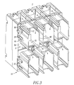
Figure 3 is an isometric view of the rear of the circuit breaker ofFigure 1 with the phase barrier members and interlocking keys in a fully assembled position. -
Figure 4 is a partially exploded isometric view of the rear of the circuit breaker ofFigure 1 , but also including a plurality of primary stabs and a plurality of finger clusters in accordance with an embodiment of the invention. -
Figure 5 is a vertical elevation view of the rear of the circuit breaker ofFigure 3 . -
Figure 6 is a vertical elevation view of two phase barrier members and one interlocking key in accordance with another embodiment of the invention. -
Figure 7 is a top plan view of two phase barrier members and two interlocking keys in accordance with another embodiment of the invention. - For purposes of illustration, embodiments of the invention will be described as applied to a three-pole circuit breaker, although it will become apparent that they could also be applied to a wide variety of electrical switching apparatus (e.g., without limitation, circuit switching devices and other circuit interrupters, such as contactors, motor starters, motor controllers and other load controllers) having any suitable plurality of poles or any suitable plurality of terminals.
- Directional phrases used herein, such as, for example, left, right, top, bottom, upper, lower, front, back and derivatives thereof, relate to the orientation of the elements shown in the drawings and are not limiting upon the claims unless expressly recited therein.
- As employed herein, the term "fastener" refers to any suitable connecting or tightening mechanism expressly including, but not limited to, screws, bolts and the combinations of bolts and nuts (e.g., without limitation, lock nuts) and bolts, washers and nuts.
- As employed herein, the term "interlocking" means locking together, uniting, or connecting in order that the position of one part or component is constrained by the position of a number of other parts or components.
- As employed herein, the term "separate" means capable of existing by itself.
- As employed herein, the statement that two or more parts are "coupled" together shall mean that the parts are joined together either directly or joined through one or more intermediate parts. Further, as employed herein, the statement that two or more parts are "attached" shall mean that the parts are joined together directly.
- As employed herein, the term "number" shall mean one or an integer greater than one (i.e., a plurality).
- Referring to
Figure 1 , the rear of acircuit breaker 2 includes a plurality of separatephase barrier members 4 and a plurality of interlocking components (e.g., interlocking keys or keys 6). As shown, thecircuit breaker 2 has two separatephase barrier apparatus Figure 1 ) line terminals 12 (shown inFigure 4 ) and the lower (with respect toFigure 1 ) load terminals 14 (shown inFigure 4 ). Each of the examplephase barrier apparatus phase barrier members 4 and twointerlocking keys 6. Each of theinterlocking keys 6 interlocks with an adjacent pair of the separatephase barrier members 4, as will be explained. This permits a single mold (not shown) to be used to manufacture the separatephase barrier members 4, which may be pre-assembled into the desired structure (e.g., without limitation, the three-polephase barrier apparatus 8,10) for a particular circuit breaker, such ascircuit breaker 2. - The interlocking
key 6 holds together two separatephase barrier members 4. This enables, for example and without limitation, two or three or four identicalphase barrier members 4 to be coupled together by one or two or three, respectively,identical interlocking keys 6, in order to be used with a respective two or three or four pole circuit breaker. For example,Figure 1 shows the three-pole circuit breaker 2. - The
phase barrier members 4 are symmetrical and twoopposite sides Figures 1-6 ) to receive pins 22 (threepins 22 are shown inFigure 1 with onekey 6 and fourpins 22 are shown in hidden line drawing inFigure 5 with one key 6) of theinterlocking key 6. Eachinterlocking key 6 is also symmetrical and has four edges 24 (threeedges 24 are shown inFigure 1 with twokeys 6 and fouredges 24 are shown in hidden line drawing inFigure 5 with one key 6), eachedge 24 with a tapered (e.g., narrower at the top left ofFigure 1 and wider at the bottom right ofFigure 1 )pin 22. When the separatephase barrier members 4 are interlocked together as an assembly in the form of the example three-polephase barrier apparatus tapered pins 22 engage the tapered (e.g., narrower at the top left ofFigure 1 and wider at the bottom right ofFigure 1 )slots 20 and add structure to such assembly. As shown inFigure 5 , two of the pins 22 (shown in hidden line drawing) of thekey 6 mate with two slots 20 (shown in hidden line drawing) of onephase barrier member 4, and the other twopins 22 mate with two slots 20 (shown in hidden line drawing) of the adjacentphase barrier member 4. - The
tapered pins 22 have protrusions 26 (twoprotrusions 26 are shown inFigure 1 ), which protrusions engage thetapered slots 20 in thesides phase barrier members 4. As shown, each of the fourtapered pins 22 defines a corresponding one of the fouredges 24. The example molded plastic taperedslots 20 are preferably resilient and flex in response to engagement with a corresponding one of the tapered pins 22 when theprotrusion 26 thereof is pressed in at theentrance 28 of a corresponding taperedslot 20. Theprotrusions 26 provide interference with thetapered slots 20 of thephase barrier member 4 when thekey 6 is pressed in. This press fit helps to hold the two adjacentphase barrier members 4 to each other. Thus, the tapered pins 22 of thekeys 6 and thetapered slots 20 of thephase barrier members 4 help to hold the separate components together to form the example three-polephase barrier apparatus - The interlocking
keys 6 include abody 7 having twoexample openings 29 therethrough. Twoscrews 30 are employed through the interlockingkey openings 29 into correspondingopenings 32 in the circuit breakerrear housing 34. Eachphase barrier member 4 hasclearance slots 36 for thescrews 30. The two adjacentphase barrier members 4 are trapped between the key 6 and therear housing 34. A number ofother screws 38 may be employed throughopenings 40 in, for example, two outside corners of two outsidephase barrier members 4 to further secure the ends of the three-polephase barrier apparatus 8 to therear housing 34. - The interlocking
key body 7 includes afirst side 42, asecond side 44 opposite and distal from thefirst side 42, and the fouredges 24 extending from thefirst side 42 to thesecond side 44. Each of theseedges 24 includes a correspondingprotrusion 26 proximate thefirst side 42 that forms at least part of the taper of a corresponding one of the tapered pins 22. - As shown in
Figure 4 , thecircuit breaker 2 includes anenclosure 46 having afirst side 48 and asecond side 50 opposite and distal from thefirst side 46. A number of separable contacts 52 (shown in simplified form in hidden line drawing) are enclosed by theenclosure 46. An operating mechanism 54 (shown in simplified form in hidden line drawing) is structured to open and close theseparable contacts 52. Theplural terminals separable contacts 52. The line andload terminals second side 50. The example three-polephase barrier apparatus second side 50. For example, thecircuit breaker 2, as shown, is a three-pole circuit breaker and each of the threeseparable contacts 52 is electrically connected between a corresponding pair of the line andload terminals - Also referring to
Figure 2 , each of the separatephase barrier members 4 includes a base 56 adjacent the enclosuresecond side 50. For each of the key openings 29 (Figure 4 ) for the screws 30 (Figure 2 ), thebase 56 includes theclearance slot 36 for the corresponding screw. The base 56 also includes theopening 40 for the fastener 38 (Figure 2 ) that fastens the base 56 to the enclosure second side 50 (Figure 4 ). - Continuing to refer to
Figures 2 and4 , each of theterminals 12,14 (Figure 4 ) includes aprimary stab 58 and afinger cluster 60. Theprimary stab 58 is electrically and mechanically connected to thefinger cluster 60 in a well-known manner. A corresponding one of the separatephase barrier members 4 is disposed substantially around thefinger cluster 60. Thephase barrier members 4 are also employed over corresponding primary stabs 58 of thecircuit breaker 2. Inside each of thephase barrier members 4, a corresponding spring loadedfinger cluster 60 is electrically and mechanically connected to a corresponding primary stab 58 (e.g., a line stab terminal or a load stab terminal of a corresponding pole) of thecircuit breaker 2. Thecircuit breaker 2, including thephase barrier members 4, the primary stabs 58 and thefinger clusters 60, is structured to be cranked into a cabinet (not shown). The cabinet includes a fixed set of stabs 62 (one fixedstab 62 is shown in phantom line drawing), each of which makes electrical and mechanical contact with a corresponding one of the spring loadedfinger clusters 60. -
Figure 3 shows thecircuit breaker 2 ofFigure 1 including thephase barrier members 4 and interlockingkeys 6 in a fully assembled position, but excluding theterminals Figure 4 . Thephase barrier members 4 prevent arcing from oneprimary stab 58 and finger cluster 60 (Figures 2 and4 ) to an adjacentprimary stab 58 andfinger cluster 60 during insertion or removal of thecircuit breaker 2 to or from the cabinet (not shown), or during an overload condition of thecircuit breaker 2. - As can be seen from
Figures 3 ,4 and6 , each of the separatephase barrier members 4 includes fourinsulative sides Figure 6 ) and a secondopen end 74. The firstopen end 72 is adjacent the enclosuresecond side 50. As shown inFigure 2 , theprimary stab 58 of theterminals 10,12 (Figure 4 ) protrudes through the firstopen end 72 of thephase barrier member 4. As shown inFigure 4 , thefinger clusters 60 are accessible through the phase barrier member second open ends 74. - Although
Figure 4 shows that theline terminals 12 are above (with respect toFigure 4 ) theload terminals 14 on the enclosuresecond side 50, it will be appreciated that any suitable orientation of theterminals - Referring to
Figures 4 and5 , the first three-polephase barrier apparatus 8 is disposed about the line terminals 12 (Figure 4 ) and the second three-polephase barrier apparatus 10 is disposed about the load terminals 14 (Figure 4 ). As best shown inFigure 5 , the first three-polephase barrier apparatus 8 is symmetrical with respect to the second three-polephase barrier apparatus 10 as both are disposed on the enclosuresecond side 50. Thesesymmetrical apparatus load terminals - As shown in
Figures 1 ,5 and6 , each of the opposingsides phase barrier members 4 includes the twoslots 20 and arunner 76 parallel to theslots 20. Each of thesides keys 6 includes the twopins 22 and arecess 82 parallel to thepins 22. Thepins 22 mate with theslots 20 and therecesses 82 mate with therunners 76. -
Figure 6 shows two separate, identicalphase barrier members 4 and one interlockingkey 6 that form anotherphase barrier apparatus 84. Thisapparatus 84 may be employed, for example, in a two-pole circuit breaker (not shown) for either two line terminals (not shown) or two load terminals (not shown) thereof. Alternatively, theapparatus 84 may be employed, for example, in a one-pole circuit breaker (not shown) in which onephase barrier member 4 is for the line terminal (not shown) and the otherphase barrier member 4 is for the load terminal (not shown). -
Figure 7 shows two separate, identicalphase barrier members 4 and twoidentical interlocking keys 6 that form anotherphase barrier apparatus 86. Here, the second interlocking key 6 (to the right ofFigure 7 ) may be employed, for example, to interlock with another phase barrier member 4 (not shown). - While specific embodiments of the invention have been described in detail, it will be appreciated by those skilled in the art that various modifications and alternatives to those details could be developed in light of the overall teachings of the disclosure. Accordingly, the particular arrangements disclosed are meant to be illustrative only and not limiting as to the scope of the invention which is to be given the full breadth of the claims appended and any and all equivalents thereof.
-
- 2
- circuit breaker
- 4
- plurality of separate phase barrier members
- 6
- plurality of interlocking components (e.g., interlocking keys or keys)
- 7
- body
- 8
- separate phase barrier apparatus
- 10
- separate phase barrier apparatus
- 12
- line terminals
- 14
- load terminals
- 16
- side
- 18
- side
- 20
- slot
- 22
- pin
- 24
- edges
- 26
- protrusions
- 28
- entrance
- 29
- openings
- 30
- screws
- 32
- openings
- 34
- circuit breaker rear housing
- 36
- clearance slots
- 38
- screws
- 40
- openings
- 42
- first side
- 44
- second side
- 46
- enclosure
- 48
- first side
- 50
- second side
- 52
- separable contacts
- 54
- operating mechanism
- 56
- base
- 58
- primary stab
- 60
- finger cluster
- 62
- fixed stab
- 64
- insulative side
- 66
- insulative side
- 68
- insulative side
- 70
- insulative side
- 72
- first open end
- 74
- second open end
- 76
- runner
- 78
- side
- 80
- side
- 82
- recess
- 84
- phase barrier apparatus
- 86
- phase barrier apparatus
Claims (22)
- A phase barrier apparatus for an electrical switching apparatus, said phase barrier apparatus comprising:a plurality of separate phase barrier members; anda number of interlocking members, each of said number of interlocking members interlocking with an adjacent pair of said separate phase barrier members.
- The phase barrier apparatus of Claim 1 wherein said plurality of separate phase barrier members comprises a first phase barrier member and a second phase barrier member, which is identical to said first phase barrier member; wherein said number of interlocking members comprises an interlocking member; and wherein the interlocking member interlocks between the first and second phase barrier members.
- The phase barrier apparatus of Claim 1 wherein said plurality of separate phase barrier members comprises a first phase barrier member, a second phase barrier member and a third phase barrier member; wherein said number of interlocking members comprises a first interlocking member and a second interlocking member; wherein the first interlocking member interlocks between the first and second phase barrier members; and wherein the second interlocking member interlocks between the second and third phase barrier members.
- The phase barrier apparatus of Claim 1 wherein each of said separate phase barrier members is symmetrical and comprises a first side with a number of slots and an opposite second side with the same number of slots; wherein each of said interlocking members is symmetrical and comprises a first side with a number of pins and an opposite second side with the same number of pins; and wherein each of said pins is structured to mate with a corresponding one of said slots.
- The phase barrier apparatus of Claim 1 wherein each of said separate phase barrier members comprises a first side with two first slots and a second side with two second slots; wherein each of said interlocking members comprises a first side with two first pins and a second side with two second pins; wherein said two first pins are structured to mate with said two first slots of one phase barrier member of said adjacent pair of said separate phase barrier members; and wherein said two second pins are structured to mate with said two second slots of the other phase barrier member of said adjacent pair of said separate phase barrier members.
- The phase barrier apparatus of Claim 1 wherein each of said separate phase barrier members comprises a first side with a number of tapered slots and a second side with a number of tapered slots; wherein each of said interlocking members comprises a first side with a number of tapered pins and a second side with a number of tapered pins; and wherein each of said tapered pins is structured to mate with a corresponding one of said tapered slots.
- The phase barrier apparatus of Claim 6 wherein said number of tapered pins is four tapered pins; wherein each of said four tapered pins includes a taper; wherein each of said number of interlocking members comprises a body including a first side, a second side opposite and distal from the last said first side, and four edges extending from the last said first side to the last said second side; wherein each of said four tapered pins defines a corresponding one of said four edges; and wherein each of said four edges includes a protrusion proximate the last said first side that forms at least part of the taper of a corresponding one of said four tapered pins.
- The phase barrier apparatus of Claim 7 wherein said number of tapered slots of said first side of said each of said separate phase barrier members is two tapered slots and said number of tapered slots of said second side of said each of said separate phase barrier members is two tapered slots; and wherein each of said tapered slots of the last said first and second sides is resilient and is structured to flex in response to engagement with a corresponding one of said tapered pins.
- An electrical switching apparatus comprising:an enclosure comprising a first side and a second side opposite and distal from said first side;a number of separable contacts enclosed by said enclosure;an operating mechanism structured to open and close said separable contacts;a plurality of terminals electrically interconnected with said number of separable contacts, said terminals protruding through the second side of said enclosure; anda number of phase barrier apparatus disposed on the second side of said enclosure, each of said number of phase barrier apparatus comprising:a plurality of separate phase barrier members, each of said separate phase barrier members being disposed about a corresponding one of said terminals, anda number of interlocking members, each of said number of interlocking members interlocking with an adjacent pair of said separate phase barrier members.
- The electrical switching apparatus of Claim 9 wherein each of said number of interlocking members comprises a body including a number of openings therethrough; and wherein each of said number of openings includes a corresponding fastener fastening said body to the second side of said enclosure.
- The electrical switching apparatus of Claim 10 wherein each of said separate phase barrier members comprises a base adjacent the second side of said enclosure; and wherein, for each of said number of openings, said base includes a clearance slot for the corresponding fastener.
- The electrical switching apparatus of Claim 9 wherein each of said separate phase barrier members comprises a base adjacent the second side of said enclosure; wherein said base includes an opening; and wherein each of a plurality of said separate phase barrier members further comprises a fastener fastening the base of said each of a plurality of said separate phase barrier members to the second side of said enclosure.
- The electrical switching apparatus of Claim 9 wherein said adjacent pair of said separate phase barrier members is engaged between a corresponding one of said number of interlocking members and the second side of said enclosure.
- The electrical switching apparatus of Claim 9 wherein each of said terminals comprises a stab electrically and mechanically connected to a finger cluster; and wherein a corresponding one of said separate phase barrier members is disposed substantially around said finger cluster.
- The electrical switching apparatus of Claim 14 wherein each of said separate phase barrier members comprises four insulative sides, a first open end and a second open end; wherein said first open end is adjacent the second side of said enclosure; wherein a corresponding one of said terminals protrudes through said first open end; and wherein said finger cluster is accessible through said second open end.
- The electrical switching apparatus of Claim 15 wherein said finger cluster is structured to be electrically and mechanically connected to a fixed stab.
- The electrical switching apparatus of Claim 9 wherein said plurality of terminals is a number of line terminals and a number of load terminals.
- The electrical switching apparatus of Claim 9 wherein said plurality of terminals is a plurality of line terminals and a plurality of load terminals.
- The electrical switching apparatus of Claim 18 wherein said line terminals are above said load terminals on the second side of said enclosure.
- The electrical switching apparatus of Claim 18 wherein said number of phase barrier apparatus is a first phase barrier apparatus disposed about said line terminals and a second phase barrier apparatus disposed about said load terminals.
- The electrical switching apparatus of Claim 20 wherein said line terminals are above said load terminals; and wherein said first phase barrier apparatus disposed on the second side of said enclosure is symmetrical to said second phase barrier apparatus as disposed on the second side of said enclosure.
- The electrical switching apparatus of Claim 9 wherein each of said separate phase barrier members comprises four sides, a first open end and a second open end; wherein said first open end is adjacent the second side of said enclosure; wherein a first side of said four sides is opposite and distal from a second side of said four sides; wherein the last said first side includes two first slots and a first runner parallel to said first slots; wherein the last said second side includes two second slots and a second runner parallel to said second slots; wherein each of said interlocking members comprises a first side including two first pins and a first recess parallel to said first pins, and a second side including two second pins and a second recess parallel to said second pins; wherein said two first pins are structured to mate with said two first slots and said first recess is structured to mate with said first runner of one phase barrier member of said adjacent pair of said separate phase barrier members; and wherein said two second pins are structured to mate with said two second slots and said second recess is structured to mate with said second runner of the other phase barrier member of said adjacent pair of said separate phase barrier members.
Applications Claiming Priority (1)
| Application Number | Priority Date | Filing Date | Title |
|---|---|---|---|
| US11/691,864 US7646271B2 (en) | 2007-03-27 | 2007-03-27 | Electrical switching apparatus and interlocking phase barrier therefor |
Publications (3)
| Publication Number | Publication Date |
|---|---|
| EP1975966A2 true EP1975966A2 (en) | 2008-10-01 |
| EP1975966A3 EP1975966A3 (en) | 2010-11-17 |
| EP1975966B1 EP1975966B1 (en) | 2012-02-08 |
Family
ID=39598413
Family Applications (1)
| Application Number | Title | Priority Date | Filing Date |
|---|---|---|---|
| EP08005867A Active EP1975966B1 (en) | 2007-03-27 | 2008-03-27 | Electrical switching apparatus and interlocking phase barrier therefor |
Country Status (5)
| Country | Link |
|---|---|
| US (1) | US7646271B2 (en) |
| EP (1) | EP1975966B1 (en) |
| CN (1) | CN101295590B (en) |
| AT (1) | ATE545146T1 (en) |
| CA (1) | CA2626985C (en) |
Cited By (1)
| Publication number | Priority date | Publication date | Assignee | Title |
|---|---|---|---|---|
| CN107908137A (en) * | 2017-12-04 | 2018-04-13 | 常熟开关制造有限公司(原常熟开关厂) | Electrical interlocking control device and its control method, automatic change-over |
Families Citing this family (9)
| Publication number | Priority date | Publication date | Assignee | Title |
|---|---|---|---|---|
| DE102010041467A1 (en) | 2010-09-27 | 2012-03-29 | Siemens Aktiengesellschaft | Multi-pole electrical switching device |
| US8730652B2 (en) | 2011-06-08 | 2014-05-20 | Schneider Electric USA, Inc. | Optimally shaped bus connector |
| DE102011087582A1 (en) * | 2011-12-01 | 2013-06-06 | Siemens Aktiengesellschaft | Multi-pole electrical switch e.g. three-pole electrical switch has connector that is pushed into channel extending in parallel to side walls, by positive connection between side walls and connector respectively |
| US9450387B2 (en) * | 2012-04-20 | 2016-09-20 | Schneider Electric USA, Inc. | Passive arc protection for main breaker line side power conductors |
| US8922977B2 (en) * | 2012-04-20 | 2014-12-30 | Schneider Electric USA, Inc. | Passive arc management system with a flue chamber |
| US9762038B2 (en) * | 2013-03-14 | 2017-09-12 | Schneider Electric USA, Inc. | Independent shutter system for rack-in breakers |
| EP2840582B1 (en) | 2013-08-21 | 2016-03-23 | Siemens Aktiengesellschaft | Angular adjustable rear stud for molded case circuit breaker |
| US9312668B2 (en) * | 2014-06-20 | 2016-04-12 | Schneider Electric USA, Inc. | Arc resistant shutters |
| US9722399B2 (en) * | 2014-11-13 | 2017-08-01 | Westinghouse Electric Company, Llc | Electrical system, and connection device and method of powering a switchgear bus in an electrical system |
Citations (5)
| Publication number | Priority date | Publication date | Assignee | Title |
|---|---|---|---|---|
| JPS5424673U (en) * | 1977-07-22 | 1979-02-17 | ||
| JPH087741A (en) * | 1994-06-20 | 1996-01-12 | Fuji Electric Co Ltd | Terminal cover of electric apparatus |
| JPH11266511A (en) * | 1998-03-17 | 1999-09-28 | Terasaki Electric Co Ltd | Terminal barrier device of circuit breaker |
| EP1130683A1 (en) * | 2000-02-29 | 2001-09-05 | GE Power Controls Belgium, besloten vennootschap met beperkte aansprakelijkheid | Power distribution device |
| EP1677329A2 (en) * | 2004-12-30 | 2006-07-05 | ABB Service S.r.l | An electrical device with fixed contacts, mobile contacts and inspectable arc chambers |
Family Cites Families (10)
| Publication number | Priority date | Publication date | Assignee | Title |
|---|---|---|---|---|
| US5157584A (en) | 1991-04-01 | 1992-10-20 | Westinghouse Electric Corp. | Power distribution apparatus with "H" shaped bus bar arrangements |
| US5200585A (en) | 1991-11-06 | 1993-04-06 | Westinghouse Electric Corp. | Drawout switchgear with improved levering-in mechanism and interlock |
| US5910757A (en) | 1998-03-25 | 1999-06-08 | Square D Company | Phase barrier for use in a multiphase circuit breaker |
| US6172585B1 (en) | 1999-08-27 | 2001-01-09 | Eaton Corporation | Circuit interrupter with base/cover attachment enabling venting |
| US6476697B2 (en) * | 2000-01-18 | 2002-11-05 | Kilovac Corporation | Modular multi-phase contactor |
| ITMI20012586A1 (en) * | 2001-12-10 | 2003-06-10 | Abb Service Srl | ELECTRIC POLE FOR A LOW VOLTAGE POWER SWITCH, AND RELATED SWITCH |
| US20040065531A1 (en) | 2002-10-08 | 2004-04-08 | Richter David N. | Blade crossbar |
| US6924721B2 (en) | 2003-07-14 | 2005-08-02 | Eaton Corporation | Gas segregator barrier for electrical switching apparatus |
| DE10348092B4 (en) * | 2003-10-16 | 2006-01-26 | Moeller Gmbh | Arrangement for busbar mounting for multiphase switching devices |
| US7009132B1 (en) * | 2004-09-03 | 2006-03-07 | Eaton Corporation | Terminal assembly for vented circuit breaker and circuit breaker incorporating same |
-
2007
- 2007-03-27 US US11/691,864 patent/US7646271B2/en active Active
-
2008
- 2008-03-26 CA CA2626985A patent/CA2626985C/en not_active Expired - Fee Related
- 2008-03-27 CN CN2008101277069A patent/CN101295590B/en active Active
- 2008-03-27 EP EP08005867A patent/EP1975966B1/en active Active
- 2008-03-27 AT AT08005867T patent/ATE545146T1/en active
Patent Citations (5)
| Publication number | Priority date | Publication date | Assignee | Title |
|---|---|---|---|---|
| JPS5424673U (en) * | 1977-07-22 | 1979-02-17 | ||
| JPH087741A (en) * | 1994-06-20 | 1996-01-12 | Fuji Electric Co Ltd | Terminal cover of electric apparatus |
| JPH11266511A (en) * | 1998-03-17 | 1999-09-28 | Terasaki Electric Co Ltd | Terminal barrier device of circuit breaker |
| EP1130683A1 (en) * | 2000-02-29 | 2001-09-05 | GE Power Controls Belgium, besloten vennootschap met beperkte aansprakelijkheid | Power distribution device |
| EP1677329A2 (en) * | 2004-12-30 | 2006-07-05 | ABB Service S.r.l | An electrical device with fixed contacts, mobile contacts and inspectable arc chambers |
Cited By (2)
| Publication number | Priority date | Publication date | Assignee | Title |
|---|---|---|---|---|
| CN107908137A (en) * | 2017-12-04 | 2018-04-13 | 常熟开关制造有限公司(原常熟开关厂) | Electrical interlocking control device and its control method, automatic change-over |
| CN107908137B (en) * | 2017-12-04 | 2019-06-28 | 常熟开关制造有限公司(原常熟开关厂) | Electrical interlocking control device and its control method, automatic change-over |
Also Published As
| Publication number | Publication date |
|---|---|
| CA2626985A1 (en) | 2008-09-27 |
| ATE545146T1 (en) | 2012-02-15 |
| CN101295590B (en) | 2012-08-29 |
| CN101295590A (en) | 2008-10-29 |
| EP1975966B1 (en) | 2012-02-08 |
| US20080237001A1 (en) | 2008-10-02 |
| EP1975966A3 (en) | 2010-11-17 |
| CA2626985C (en) | 2015-10-20 |
| US7646271B2 (en) | 2010-01-12 |
Similar Documents
| Publication | Publication Date | Title |
|---|---|---|
| CA2626985C (en) | Electrical switching apparatus and interlocking phase barrier therefor | |
| US4809132A (en) | Field installable line and load lug connectors for molded case circuit breakers | |
| US5761026A (en) | Snap-on circuit breaker mounting system | |
| JP6454036B2 (en) | DC circuit breaker | |
| US7586057B2 (en) | Electrical switching apparatus and vented case therefor | |
| EP1986206A1 (en) | Electrical switching apparatus, and arc hood assembly and chimney therefor | |
| JP6468504B2 (en) | DC circuit breaker | |
| US5027091A (en) | Molded case circuit interrupter rating plug keying and interlock arrangement | |
| EP1956624B1 (en) | Slot motor housing and circuit interrupter including the same | |
| US9129768B2 (en) | Multipole electrical switching device | |
| CN109155211B (en) | Hybrid MCCB employing electromechanical contacts and power electronics | |
| US6531941B1 (en) | Clip for a conductor in a rotary breaker | |
| US6064018A (en) | Molded case circuit breaker molded pole assembly | |
| US6429760B1 (en) | Cross bar for a conductor in a rotary breaker | |
| US3979675A (en) | Circuit interrupter | |
| US9053888B2 (en) | Tie bar for molded case circuit breaker and method of assembly | |
| US6005207A (en) | Multi-part circuit breaker housing | |
| US8378243B2 (en) | Arrangement comprising at least two separate switch pole housings and having a joining facility for joining the switch pole housings and a multi-pole electric switching device comprising such an arrangement | |
| US9263860B2 (en) | Power distribution system, and switchgear assembly, and mounting member therefor | |
| US20020027489A1 (en) | Circuit breaker support and assembly | |
| US20120073945A1 (en) | Multipole Electrical Switching Device | |
| KR101994444B1 (en) | Circuit Breaker for DC | |
| KR200496737Y1 (en) | Trip Device of Molded Case Circuit Breaker | |
| US10090129B1 (en) | Housing assembly for an electrical switch | |
| KR101890685B1 (en) | Molded Case Circuit Breaker for DC |
Legal Events
| Date | Code | Title | Description |
|---|---|---|---|
| PUAI | Public reference made under article 153(3) epc to a published international application that has entered the european phase |
Free format text: ORIGINAL CODE: 0009012 |
|
| AK | Designated contracting states |
Kind code of ref document: A2 Designated state(s): AT BE BG CH CY CZ DE DK EE ES FI FR GB GR HR HU IE IS IT LI LT LU LV MC MT NL NO PL PT RO SE SI SK TR |
|
| AX | Request for extension of the european patent |
Extension state: AL BA MK RS |
|
| PUAL | Search report despatched |
Free format text: ORIGINAL CODE: 0009013 |
|
| AK | Designated contracting states |
Kind code of ref document: A3 Designated state(s): AT BE BG CH CY CZ DE DK EE ES FI FR GB GR HR HU IE IS IT LI LT LU LV MC MT NL NO PL PT RO SE SI SK TR |
|
| AX | Request for extension of the european patent |
Extension state: AL BA MK RS |
|
| RIC1 | Information provided on ipc code assigned before grant |
Ipc: H01H 71/08 20060101ALI20101011BHEP Ipc: H01H 71/02 20060101AFI20080722BHEP Ipc: H01H 9/02 20060101ALI20101011BHEP |
|
| 17P | Request for examination filed |
Effective date: 20110517 |
|
| GRAP | Despatch of communication of intention to grant a patent |
Free format text: ORIGINAL CODE: EPIDOSNIGR1 |
|
| AKX | Designation fees paid |
Designated state(s): AT BE BG CH CY CZ DE DK EE ES FI FR GB GR HR HU IE IS IT LI LT LU LV MC MT NL NO PL PT RO SE SI SK TR |
|
| RIC1 | Information provided on ipc code assigned before grant |
Ipc: H01H 71/02 20060101AFI20110629BHEP Ipc: H01H 71/08 20060101ALI20110629BHEP Ipc: H01H 9/02 20060101ALI20110629BHEP |
|
| GRAS | Grant fee paid |
Free format text: ORIGINAL CODE: EPIDOSNIGR3 |
|
| GRAA | (expected) grant |
Free format text: ORIGINAL CODE: 0009210 |
|
| AK | Designated contracting states |
Kind code of ref document: B1 Designated state(s): AT BE BG CH CY CZ DE DK EE ES FI FR GB GR HR HU IE IS IT LI LT LU LV MC MT NL NO PL PT RO SE SI SK TR |
|
| REG | Reference to a national code |
Ref country code: GB Ref legal event code: FG4D |
|
| REG | Reference to a national code |
Ref country code: AT Ref legal event code: REF Ref document number: 545146 Country of ref document: AT Kind code of ref document: T Effective date: 20120215 Ref country code: CH Ref legal event code: EP |
|
| REG | Reference to a national code |
Ref country code: DE Ref legal event code: R096 Ref document number: 602008013181 Country of ref document: DE Effective date: 20120405 |
|
| REG | Reference to a national code |
Ref country code: NL Ref legal event code: VDEP Effective date: 20120208 |
|
| LTIE | Lt: invalidation of european patent or patent extension |
Effective date: 20120208 |
|
| PG25 | Lapsed in a contracting state [announced via postgrant information from national office to epo] |
Ref country code: HR Free format text: LAPSE BECAUSE OF FAILURE TO SUBMIT A TRANSLATION OF THE DESCRIPTION OR TO PAY THE FEE WITHIN THE PRESCRIBED TIME-LIMIT Effective date: 20120208 Ref country code: NO Free format text: LAPSE BECAUSE OF FAILURE TO SUBMIT A TRANSLATION OF THE DESCRIPTION OR TO PAY THE FEE WITHIN THE PRESCRIBED TIME-LIMIT Effective date: 20120508 Ref country code: LT Free format text: LAPSE BECAUSE OF FAILURE TO SUBMIT A TRANSLATION OF THE DESCRIPTION OR TO PAY THE FEE WITHIN THE PRESCRIBED TIME-LIMIT Effective date: 20120208 Ref country code: IS Free format text: LAPSE BECAUSE OF FAILURE TO SUBMIT A TRANSLATION OF THE DESCRIPTION OR TO PAY THE FEE WITHIN THE PRESCRIBED TIME-LIMIT Effective date: 20120608 Ref country code: NL Free format text: LAPSE BECAUSE OF FAILURE TO SUBMIT A TRANSLATION OF THE DESCRIPTION OR TO PAY THE FEE WITHIN THE PRESCRIBED TIME-LIMIT Effective date: 20120208 |
|
| PG25 | Lapsed in a contracting state [announced via postgrant information from national office to epo] |
Ref country code: BE Free format text: LAPSE BECAUSE OF FAILURE TO SUBMIT A TRANSLATION OF THE DESCRIPTION OR TO PAY THE FEE WITHIN THE PRESCRIBED TIME-LIMIT Effective date: 20120208 Ref country code: FI Free format text: LAPSE BECAUSE OF FAILURE TO SUBMIT A TRANSLATION OF THE DESCRIPTION OR TO PAY THE FEE WITHIN THE PRESCRIBED TIME-LIMIT Effective date: 20120208 Ref country code: PT Free format text: LAPSE BECAUSE OF FAILURE TO SUBMIT A TRANSLATION OF THE DESCRIPTION OR TO PAY THE FEE WITHIN THE PRESCRIBED TIME-LIMIT Effective date: 20120608 Ref country code: GR Free format text: LAPSE BECAUSE OF FAILURE TO SUBMIT A TRANSLATION OF THE DESCRIPTION OR TO PAY THE FEE WITHIN THE PRESCRIBED TIME-LIMIT Effective date: 20120509 Ref country code: PL Free format text: LAPSE BECAUSE OF FAILURE TO SUBMIT A TRANSLATION OF THE DESCRIPTION OR TO PAY THE FEE WITHIN THE PRESCRIBED TIME-LIMIT Effective date: 20120208 Ref country code: LV Free format text: LAPSE BECAUSE OF FAILURE TO SUBMIT A TRANSLATION OF THE DESCRIPTION OR TO PAY THE FEE WITHIN THE PRESCRIBED TIME-LIMIT Effective date: 20120208 |
|
| REG | Reference to a national code |
Ref country code: AT Ref legal event code: MK05 Ref document number: 545146 Country of ref document: AT Kind code of ref document: T Effective date: 20120208 |
|
| PG25 | Lapsed in a contracting state [announced via postgrant information from national office to epo] |
Ref country code: CY Free format text: LAPSE BECAUSE OF FAILURE TO SUBMIT A TRANSLATION OF THE DESCRIPTION OR TO PAY THE FEE WITHIN THE PRESCRIBED TIME-LIMIT Effective date: 20120208 |
|
| PG25 | Lapsed in a contracting state [announced via postgrant information from national office to epo] |
Ref country code: MC Free format text: LAPSE BECAUSE OF NON-PAYMENT OF DUE FEES Effective date: 20120331 Ref country code: RO Free format text: LAPSE BECAUSE OF FAILURE TO SUBMIT A TRANSLATION OF THE DESCRIPTION OR TO PAY THE FEE WITHIN THE PRESCRIBED TIME-LIMIT Effective date: 20120208 Ref country code: SI Free format text: LAPSE BECAUSE OF FAILURE TO SUBMIT A TRANSLATION OF THE DESCRIPTION OR TO PAY THE FEE WITHIN THE PRESCRIBED TIME-LIMIT Effective date: 20120208 Ref country code: EE Free format text: LAPSE BECAUSE OF FAILURE TO SUBMIT A TRANSLATION OF THE DESCRIPTION OR TO PAY THE FEE WITHIN THE PRESCRIBED TIME-LIMIT Effective date: 20120208 Ref country code: CZ Free format text: LAPSE BECAUSE OF FAILURE TO SUBMIT A TRANSLATION OF THE DESCRIPTION OR TO PAY THE FEE WITHIN THE PRESCRIBED TIME-LIMIT Effective date: 20120208 Ref country code: SE Free format text: LAPSE BECAUSE OF FAILURE TO SUBMIT A TRANSLATION OF THE DESCRIPTION OR TO PAY THE FEE WITHIN THE PRESCRIBED TIME-LIMIT Effective date: 20120208 Ref country code: DK Free format text: LAPSE BECAUSE OF FAILURE TO SUBMIT A TRANSLATION OF THE DESCRIPTION OR TO PAY THE FEE WITHIN THE PRESCRIBED TIME-LIMIT Effective date: 20120208 |
|
| REG | Reference to a national code |
Ref country code: CH Ref legal event code: PL |
|
| PG25 | Lapsed in a contracting state [announced via postgrant information from national office to epo] |
Ref country code: SK Free format text: LAPSE BECAUSE OF FAILURE TO SUBMIT A TRANSLATION OF THE DESCRIPTION OR TO PAY THE FEE WITHIN THE PRESCRIBED TIME-LIMIT Effective date: 20120208 |
|
| PLBE | No opposition filed within time limit |
Free format text: ORIGINAL CODE: 0009261 |
|
| STAA | Information on the status of an ep patent application or granted ep patent |
Free format text: STATUS: NO OPPOSITION FILED WITHIN TIME LIMIT |
|
| REG | Reference to a national code |
Ref country code: IE Ref legal event code: MM4A |
|
| 26N | No opposition filed |
Effective date: 20121109 |
|
| PG25 | Lapsed in a contracting state [announced via postgrant information from national office to epo] |
Ref country code: CH Free format text: LAPSE BECAUSE OF NON-PAYMENT OF DUE FEES Effective date: 20120331 Ref country code: AT Free format text: LAPSE BECAUSE OF FAILURE TO SUBMIT A TRANSLATION OF THE DESCRIPTION OR TO PAY THE FEE WITHIN THE PRESCRIBED TIME-LIMIT Effective date: 20120208 Ref country code: LI Free format text: LAPSE BECAUSE OF NON-PAYMENT OF DUE FEES Effective date: 20120331 Ref country code: IE Free format text: LAPSE BECAUSE OF NON-PAYMENT OF DUE FEES Effective date: 20120327 |
|
| REG | Reference to a national code |
Ref country code: DE Ref legal event code: R097 Ref document number: 602008013181 Country of ref document: DE Effective date: 20121109 |
|
| PG25 | Lapsed in a contracting state [announced via postgrant information from national office to epo] |
Ref country code: ES Free format text: LAPSE BECAUSE OF FAILURE TO SUBMIT A TRANSLATION OF THE DESCRIPTION OR TO PAY THE FEE WITHIN THE PRESCRIBED TIME-LIMIT Effective date: 20120519 |
|
| PG25 | Lapsed in a contracting state [announced via postgrant information from national office to epo] |
Ref country code: BG Free format text: LAPSE BECAUSE OF FAILURE TO SUBMIT A TRANSLATION OF THE DESCRIPTION OR TO PAY THE FEE WITHIN THE PRESCRIBED TIME-LIMIT Effective date: 20120508 Ref country code: MT Free format text: LAPSE BECAUSE OF FAILURE TO SUBMIT A TRANSLATION OF THE DESCRIPTION OR TO PAY THE FEE WITHIN THE PRESCRIBED TIME-LIMIT Effective date: 20120208 |
|
| PG25 | Lapsed in a contracting state [announced via postgrant information from national office to epo] |
Ref country code: TR Free format text: LAPSE BECAUSE OF FAILURE TO SUBMIT A TRANSLATION OF THE DESCRIPTION OR TO PAY THE FEE WITHIN THE PRESCRIBED TIME-LIMIT Effective date: 20120208 |
|
| PG25 | Lapsed in a contracting state [announced via postgrant information from national office to epo] |
Ref country code: LU Free format text: LAPSE BECAUSE OF NON-PAYMENT OF DUE FEES Effective date: 20120327 |
|
| PG25 | Lapsed in a contracting state [announced via postgrant information from national office to epo] |
Ref country code: HU Free format text: LAPSE BECAUSE OF FAILURE TO SUBMIT A TRANSLATION OF THE DESCRIPTION OR TO PAY THE FEE WITHIN THE PRESCRIBED TIME-LIMIT Effective date: 20080327 |
|
| REG | Reference to a national code |
Ref country code: FR Ref legal event code: PLFP Year of fee payment: 9 |
|
| PGFP | Annual fee paid to national office [announced via postgrant information from national office to epo] |
Ref country code: GB Payment date: 20160224 Year of fee payment: 9 |
|
| REG | Reference to a national code |
Ref country code: FR Ref legal event code: PLFP Year of fee payment: 10 |
|
| GBPC | Gb: european patent ceased through non-payment of renewal fee |
Effective date: 20170327 |
|
| REG | Reference to a national code |
Ref country code: FR Ref legal event code: PLFP Year of fee payment: 11 |
|
| PG25 | Lapsed in a contracting state [announced via postgrant information from national office to epo] |
Ref country code: GB Free format text: LAPSE BECAUSE OF NON-PAYMENT OF DUE FEES Effective date: 20170327 |
|
| REG | Reference to a national code |
Ref country code: DE Ref legal event code: R082 Ref document number: 602008013181 Country of ref document: DE Ref country code: DE Ref legal event code: R081 Ref document number: 602008013181 Country of ref document: DE Owner name: EATON INTELLIGENT POWER LIMITED, IE Free format text: FORMER OWNER: EATON CORPORATION, CLEVELAND, OHIO, US |
|
| PGFP | Annual fee paid to national office [announced via postgrant information from national office to epo] |
Ref country code: FR Payment date: 20230222 Year of fee payment: 16 |
|
| PGFP | Annual fee paid to national office [announced via postgrant information from national office to epo] |
Ref country code: IT Payment date: 20230221 Year of fee payment: 16 Ref country code: DE Payment date: 20230221 Year of fee payment: 16 |
|
| P01 | Opt-out of the competence of the unified patent court (upc) registered |
Effective date: 20230521 |