EP1977289B1 - Process cartridge and image forming apparatus - Google Patents
Process cartridge and image forming apparatus Download PDFInfo
- Publication number
- EP1977289B1 EP1977289B1 EP07706929.2A EP07706929A EP1977289B1 EP 1977289 B1 EP1977289 B1 EP 1977289B1 EP 07706929 A EP07706929 A EP 07706929A EP 1977289 B1 EP1977289 B1 EP 1977289B1
- Authority
- EP
- European Patent Office
- Prior art keywords
- force
- force receiving
- process cartridge
- receiving portion
- application member
- Prior art date
- Legal status (The legal status is an assumption and is not a legal conclusion. Google has not performed a legal analysis and makes no representation as to the accuracy of the status listed.)
- Active
Links
- 238000000034 method Methods 0.000 title claims description 155
- 230000008569 process Effects 0.000 title claims description 155
- 230000008878 coupling Effects 0.000 claims description 30
- 238000010168 coupling process Methods 0.000 claims description 30
- 238000005859 coupling reaction Methods 0.000 claims description 30
- 238000012546 transfer Methods 0.000 claims description 19
- 230000001105 regulatory effect Effects 0.000 claims description 14
- 230000008859 change Effects 0.000 claims description 9
- 239000000463 material Substances 0.000 claims description 6
- 230000000694 effects Effects 0.000 description 6
- 230000007246 mechanism Effects 0.000 description 6
- 238000011144 upstream manufacturing Methods 0.000 description 6
- 238000004140 cleaning Methods 0.000 description 4
- 230000004048 modification Effects 0.000 description 4
- 238000012986 modification Methods 0.000 description 4
- 230000002093 peripheral effect Effects 0.000 description 4
- 230000015572 biosynthetic process Effects 0.000 description 2
- 239000003086 colorant Substances 0.000 description 2
- 238000011161 development Methods 0.000 description 2
- 230000018109 developmental process Effects 0.000 description 2
- 238000007599 discharging Methods 0.000 description 2
- 230000005489 elastic deformation Effects 0.000 description 2
- 230000001419 dependent effect Effects 0.000 description 1
- 230000007774 longterm Effects 0.000 description 1
- 238000012423 maintenance Methods 0.000 description 1
- 239000002245 particle Substances 0.000 description 1
Images


Classifications
-
- G—PHYSICS
- G03—PHOTOGRAPHY; CINEMATOGRAPHY; ANALOGOUS TECHNIQUES USING WAVES OTHER THAN OPTICAL WAVES; ELECTROGRAPHY; HOLOGRAPHY
- G03G—ELECTROGRAPHY; ELECTROPHOTOGRAPHY; MAGNETOGRAPHY
- G03G21/00—Arrangements not provided for by groups G03G13/00 - G03G19/00, e.g. cleaning, elimination of residual charge
- G03G21/16—Mechanical means for facilitating the maintenance of the apparatus, e.g. modular arrangements
- G03G21/1604—Arrangement or disposition of the entire apparatus
- G03G21/1623—Means to access the interior of the apparatus
-
- G—PHYSICS
- G03—PHOTOGRAPHY; CINEMATOGRAPHY; ANALOGOUS TECHNIQUES USING WAVES OTHER THAN OPTICAL WAVES; ELECTROGRAPHY; HOLOGRAPHY
- G03G—ELECTROGRAPHY; ELECTROPHOTOGRAPHY; MAGNETOGRAPHY
- G03G21/00—Arrangements not provided for by groups G03G13/00 - G03G19/00, e.g. cleaning, elimination of residual charge
- G03G21/16—Mechanical means for facilitating the maintenance of the apparatus, e.g. modular arrangements
- G03G21/18—Mechanical means for facilitating the maintenance of the apparatus, e.g. modular arrangements using a processing cartridge, whereby the process cartridge comprises at least two image processing means in a single unit
- G03G21/1803—Arrangements or disposition of the complete process cartridge or parts thereof
- G03G21/1814—Details of parts of process cartridge, e.g. for charging, transfer, cleaning, developing
-
- G—PHYSICS
- G03—PHOTOGRAPHY; CINEMATOGRAPHY; ANALOGOUS TECHNIQUES USING WAVES OTHER THAN OPTICAL WAVES; ELECTROGRAPHY; HOLOGRAPHY
- G03G—ELECTROGRAPHY; ELECTROPHOTOGRAPHY; MAGNETOGRAPHY
- G03G21/00—Arrangements not provided for by groups G03G13/00 - G03G19/00, e.g. cleaning, elimination of residual charge
- G03G21/16—Mechanical means for facilitating the maintenance of the apparatus, e.g. modular arrangements
- G03G21/18—Mechanical means for facilitating the maintenance of the apparatus, e.g. modular arrangements using a processing cartridge, whereby the process cartridge comprises at least two image processing means in a single unit
-
- G—PHYSICS
- G03—PHOTOGRAPHY; CINEMATOGRAPHY; ANALOGOUS TECHNIQUES USING WAVES OTHER THAN OPTICAL WAVES; ELECTROGRAPHY; HOLOGRAPHY
- G03G—ELECTROGRAPHY; ELECTROPHOTOGRAPHY; MAGNETOGRAPHY
- G03G15/00—Apparatus for electrographic processes using a charge pattern
-
- G—PHYSICS
- G03—PHOTOGRAPHY; CINEMATOGRAPHY; ANALOGOUS TECHNIQUES USING WAVES OTHER THAN OPTICAL WAVES; ELECTROGRAPHY; HOLOGRAPHY
- G03G—ELECTROGRAPHY; ELECTROPHOTOGRAPHY; MAGNETOGRAPHY
- G03G15/00—Apparatus for electrographic processes using a charge pattern
- G03G15/02—Apparatus for electrographic processes using a charge pattern for laying down a uniform charge, e.g. for sensitising; Corona discharge devices
-
- G—PHYSICS
- G03—PHOTOGRAPHY; CINEMATOGRAPHY; ANALOGOUS TECHNIQUES USING WAVES OTHER THAN OPTICAL WAVES; ELECTROGRAPHY; HOLOGRAPHY
- G03G—ELECTROGRAPHY; ELECTROPHOTOGRAPHY; MAGNETOGRAPHY
- G03G21/00—Arrangements not provided for by groups G03G13/00 - G03G19/00, e.g. cleaning, elimination of residual charge
- G03G21/16—Mechanical means for facilitating the maintenance of the apparatus, e.g. modular arrangements
- G03G21/1642—Mechanical means for facilitating the maintenance of the apparatus, e.g. modular arrangements for connecting the different parts of the apparatus
- G03G21/1647—Mechanical connection means
-
- G—PHYSICS
- G03—PHOTOGRAPHY; CINEMATOGRAPHY; ANALOGOUS TECHNIQUES USING WAVES OTHER THAN OPTICAL WAVES; ELECTROGRAPHY; HOLOGRAPHY
- G03G—ELECTROGRAPHY; ELECTROPHOTOGRAPHY; MAGNETOGRAPHY
- G03G21/00—Arrangements not provided for by groups G03G13/00 - G03G19/00, e.g. cleaning, elimination of residual charge
- G03G21/16—Mechanical means for facilitating the maintenance of the apparatus, e.g. modular arrangements
- G03G21/1661—Mechanical means for facilitating the maintenance of the apparatus, e.g. modular arrangements means for handling parts of the apparatus in the apparatus
- G03G21/1676—Mechanical means for facilitating the maintenance of the apparatus, e.g. modular arrangements means for handling parts of the apparatus in the apparatus for the developer unit
-
- G—PHYSICS
- G03—PHOTOGRAPHY; CINEMATOGRAPHY; ANALOGOUS TECHNIQUES USING WAVES OTHER THAN OPTICAL WAVES; ELECTROGRAPHY; HOLOGRAPHY
- G03G—ELECTROGRAPHY; ELECTROPHOTOGRAPHY; MAGNETOGRAPHY
- G03G21/00—Arrangements not provided for by groups G03G13/00 - G03G19/00, e.g. cleaning, elimination of residual charge
- G03G21/16—Mechanical means for facilitating the maintenance of the apparatus, e.g. modular arrangements
- G03G21/18—Mechanical means for facilitating the maintenance of the apparatus, e.g. modular arrangements using a processing cartridge, whereby the process cartridge comprises at least two image processing means in a single unit
- G03G21/1803—Arrangements or disposition of the complete process cartridge or parts thereof
- G03G21/1817—Arrangements or disposition of the complete process cartridge or parts thereof having a submodular arrangement
- G03G21/1825—Pivotable subunit connection
-
- G—PHYSICS
- G03—PHOTOGRAPHY; CINEMATOGRAPHY; ANALOGOUS TECHNIQUES USING WAVES OTHER THAN OPTICAL WAVES; ELECTROGRAPHY; HOLOGRAPHY
- G03G—ELECTROGRAPHY; ELECTROPHOTOGRAPHY; MAGNETOGRAPHY
- G03G21/00—Arrangements not provided for by groups G03G13/00 - G03G19/00, e.g. cleaning, elimination of residual charge
- G03G21/16—Mechanical means for facilitating the maintenance of the apparatus, e.g. modular arrangements
- G03G21/18—Mechanical means for facilitating the maintenance of the apparatus, e.g. modular arrangements using a processing cartridge, whereby the process cartridge comprises at least two image processing means in a single unit
- G03G21/1839—Means for handling the process cartridge in the apparatus body
- G03G21/1842—Means for handling the process cartridge in the apparatus body for guiding and mounting the process cartridge, positioning, alignment, locks
-
- G—PHYSICS
- G03—PHOTOGRAPHY; CINEMATOGRAPHY; ANALOGOUS TECHNIQUES USING WAVES OTHER THAN OPTICAL WAVES; ELECTROGRAPHY; HOLOGRAPHY
- G03G—ELECTROGRAPHY; ELECTROPHOTOGRAPHY; MAGNETOGRAPHY
- G03G2215/00—Apparatus for electrophotographic processes
- G03G2215/01—Apparatus for electrophotographic processes for producing multicoloured copies
- G03G2215/0103—Plural electrographic recording members
- G03G2215/0119—Linear arrangement adjacent plural transfer points
-
- G—PHYSICS
- G03—PHOTOGRAPHY; CINEMATOGRAPHY; ANALOGOUS TECHNIQUES USING WAVES OTHER THAN OPTICAL WAVES; ELECTROGRAPHY; HOLOGRAPHY
- G03G—ELECTROGRAPHY; ELECTROPHOTOGRAPHY; MAGNETOGRAPHY
- G03G2221/00—Processes not provided for by group G03G2215/00, e.g. cleaning or residual charge elimination
- G03G2221/16—Mechanical means for facilitating the maintenance of the apparatus, e.g. modular arrangements and complete machine concepts
- G03G2221/1678—Frame structures
- G03G2221/169—Structural door designs
-
- G—PHYSICS
- G03—PHOTOGRAPHY; CINEMATOGRAPHY; ANALOGOUS TECHNIQUES USING WAVES OTHER THAN OPTICAL WAVES; ELECTROGRAPHY; HOLOGRAPHY
- G03G—ELECTROGRAPHY; ELECTROPHOTOGRAPHY; MAGNETOGRAPHY
- G03G2221/00—Processes not provided for by group G03G2215/00, e.g. cleaning or residual charge elimination
- G03G2221/16—Mechanical means for facilitating the maintenance of the apparatus, e.g. modular arrangements and complete machine concepts
- G03G2221/18—Cartridge systems
- G03G2221/183—Process cartridge
- G03G2221/1853—Process cartridge having a submodular arrangement
- G03G2221/1861—Rotational subunit connection
-
- G—PHYSICS
- G03—PHOTOGRAPHY; CINEMATOGRAPHY; ANALOGOUS TECHNIQUES USING WAVES OTHER THAN OPTICAL WAVES; ELECTROGRAPHY; HOLOGRAPHY
- G03G—ELECTROGRAPHY; ELECTROPHOTOGRAPHY; MAGNETOGRAPHY
- G03G2221/00—Processes not provided for by group G03G2215/00, e.g. cleaning or residual charge elimination
- G03G2221/16—Mechanical means for facilitating the maintenance of the apparatus, e.g. modular arrangements and complete machine concepts
- G03G2221/18—Cartridge systems
- G03G2221/183—Process cartridge
- G03G2221/1853—Process cartridge having a submodular arrangement
- G03G2221/1869—Cartridge holders, e.g. intermediate frames for placing cartridge parts therein
Definitions
- the present invention relates to a process cartridge in which an electrophotographic photosensitive drum and a developing roller actable on the electrophotographic photosensitive drum which are contactable to each other and spaceable from each other, and an electrophotographic image forming apparatus to which said process cartridge is detachably mountable.
- a process cartridge type is conventional wherein an electrophotographic photosensitive drum and a developing roller actable on the electrophotographic photosensitive drum are unified into a process cartridge detachably mountable to a main assembly of the image forming apparatus.
- the process cartridge type With the process cartridge type, the maintenance operation of the apparatus can be carried out in effect without the service person. Therefore, the process cartridge type is widely used in the field of electrophotographic image forming apparatus.
- the developing roller When the image forming operation is carried out, the developing roller is kept urged to the electrophotographic photosensitive drum at a predetermined pressure.
- an elastic layer of the developing roller In a contact developing system in which a developing roller is contacted to the photosensitive drum during the developing operation, an elastic layer of the developing roller is in contact to the surface of the photosensitive drum at the predetermined pressure.
- the elastic layer of the developing roller may be deformed. If this occurs, non-uniformity may result in the formed image. Since the developing roller is contacted to the photosensitive drum, a developer may be depositedofrom the developing roller to the photosensitive drum. Since the photosensitive drum and the developing roller are rotated in contact with each other even when the developing operation is not carried out.
- an image forming apparatus in which when the image forming operation is not carried out, a mechanism act on the process cartridge to space the developing roller from the electrophotographic photosensitive drum (Japanese Laid-open Patent Application 2003-167499 ).
- the process cartridge comprises a photosensitive member unit having a photosensitive drum, and a developing unit for supporting the developing roller swingably provided in the photosensitive member unit.
- a spacing plate provided in the main assembly of the image forming apparatus
- a force receiving portion provided in the developing unit receives a force from the spacing plate.
- the developing roller moves away from the photosensitive drum.
- the force receiving portion for spacing the developing roller from the photosensitive drum is projected from the outer configuration of the developing unit. Therefore, when the user handles the process cartridge, and/or when the process cartridge is transported, the force receiving portion tends to be damaged.
- the existence of the force receiving portion may object to downsizing of the process cartridge in which the electrophotographic photosensitive drum and the developing roller are contactable to each other and spaceable from each other and the main assembly of the image forming apparatus to which the process cartridge is detachably mountable.
- the force receiving portion when the process cartridge is handled, or when the process cartridge is transported, the force receiving portion is not damaged.
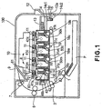
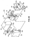
- Figure 1 shows an electrophotographic image forming apparatus (main assembly of the apparatus) 100 including process cartridges (cartridges) 50y, 50m, 50c, 50k detachably mounted.
- the cartridges 50y, 50m, 50c, 50k contain or accommodate yellow color toner (developer), magenta color toner (developer), cyan color toner (developer) and black color toner (developer), respectively.
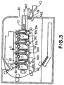
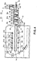
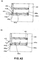
- Figure 2 is a sectional side elevation of the cartridge alone; Figures 3 and 4 are illustrations of removing the cartridges 50y, 50m, 50c, 50k from the main assembly 100 of the apparatus.
- the main assembly 100 of the apparatus the electrophotographic photosensitive drums (photosensitive drums) 30y, 30m, 30c, 30k are exposed to the laser beams 11 modulated in accordance with the image signal by the laser scanner 10, so that electrostatic latent images are formed on the surfaces.
- the electrostatic latent images are developed by developing rollers 42 into toner images (developed images) on the respective surfaces of the photosensitive drums 30.
- the transfer rollers 18y, 18m, 18c, 18k By applying voltages to the transfer rollers 18y, 18m, 18c, 18k, the toner images of respective colors formed on the photosensitive drums 30y, 30m, 30c, 30k are sequentially transferred onto the transfer belt 19.
- the toner image formed on the transfer belt 19 is transferred by the transfer roller 3 onto the recording material P fed by the feeding roller 1 (feeding means).
- the recording material P is fed to the fixing unit 6 including a driving roller and a fixing roller containing a heater.
- the toner image transferred onto the recording material P is fixed.
- the recording material having the toner image fixed thereon is discharged to a discharging portion 9 by a pair 7 of discharging rollers.
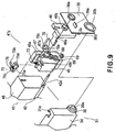
- the cartridges 50y, 50m, 50c and 50k of this embodiment will be described. Since the cartridges 50y, 50m, 50c, 50k are all the same except that the colors contained therein are different from each other, the following description will be made only as to the cartridge 50y.
- the cartridge 50y includes a photosensitive drum 30, process means actable on the photosensitive drum 30.
- the process means includes a charging roller 32 functioning as charging means for charging electrically the photosensitive drum 30, a developing roller 42 functioning as developing means for developing a latent image formed on the photosensitive drum 30, and/or blade 33 functioning as cleaning means for removing residual toner remaining on the surface of the photosensitive drum 30.
- the cartridge 50y comprises a drum unit 31 and a developing unit 41.
- the drum unit 31 contains the photosensitive drum 30, the charging means 32, the cleaning means 33, the residual toner accommodating portion 35, the drum frame 34, and the covering members 36, 37.
- One longitudinal end of the photosensitive drum 30, as shown in Figure 9 is supported rotatably by a supporting portion 36b of the covering member 36.
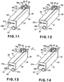
- the other longitudinal end of the photosensitive drum 30, as shown in Figure 11 - Figure 14 is rotatably supported by a supporting portion 37b of a covering member 37.
- the covering members 36, 37 are fixed to the drum frame 34 at the opposite longitudinal ends of the drum frame 34.
- one longitudinal end of the photosensitive drum 30 is provided with a coupling member 30a for receiving a driving force for rotating the photosensitive drum 30.
- the coupling member 30a is engaged with first main assembly coupling member 105 shown in Figures 4 , 30 when the cartridge 50y is mounted to the main assembly 100 of the apparatus.
- the photosensitive drum 30 is rotated in the direction of an arrow u as shown in Figure 2 by a driving force transmitted from a driving motor (unshown) provided in the main assembly 100 of the apparatus to the coupling member 30a.
- the charging means 32 is supported on the drum frame 34 and is rotated by the photosensitive drum 30 to which the charging means 32 is contacted.
- the cleaning means 33 is supported by the drum frame 34 and is contacted to the peripheral surface of the photosensitive drum 30.
- the covering members 36, 37 are provided with supporting hole portions 36a, 37a for rotatably (movably) supporting the developing unit 41.
- the developing unit 41 contains the developing roller 42, the developing blade 43, the developing device frame 48, the bearing unit 45 and the covering member 46.
- the developing device frame 48 comprises a toner accommodating portion 49 for accommodating the toner to be supplied to the developing roller 42, and a developing blade 43 for regulating a layer thickness of the toner of the peripheral surface of the developing roller 42.
- the bearing unit 45 is fixed to the one longitudinal end side of the developing device frame 48, and supports rotatably the developing roller. 42 having a developing roller gear 69 at the end thereof.
- the bearing unit 45 is provided with a coupling member 67, an idler gear 68 for transmitting a driving force to the developing roller gear 69 from the coupling member 67.
- the covering member 46 is fixed to the longitudinally outside of the bearing unit 45 so as to cover the coupling member 67 and the idler gear 68.
- the covering member 46 is provided with a cylindrical portion 46b which is projected beyond the surface of the covering member 46.
- the coupling member 67 is exposed through an inside opening of the cylindrical portion 46b.
- the coupling member 67 is engaged with the second main assembly coupling member 106 shown in Figure 30 to transmit the driving force from the driving motor (unshown) provided in the main assembly 100 of the apparatus when the cartridge 50y is mounted to the main assembly 100 of the apparatus.
- the developing unit 41 is urged in the direction of an arrow G by the urging force of the urging spring 95 so that developing unit 41 receives a moment H about the cylindrical portion 46b and the projected portion 48b.
- the developing roller 42 can be contacted to the photosensitive drum 30 with a predetermined pressure.
- the position of the developing unit 41 at this time is "contact position".
- the urging spring 95 of this embodiment is provided on the end which is opposite the one longitudinal end provided with the coupling member 30a for the photosensitive drum 30 and with the coupling member 67 for the developing roller gear 69. Because of such a structure, the force g ( Figure 6 ) received by the first force receiving member 75 of a force receiving device 90 (which will be described hereinafter) which is provided on the one longitudinal end, from the first force application member 61, produces a moment about the cylindrical portion 46b in the developing unit 41. In other words, at the one longitudinal end, the moment h thus produced is effective to urge the developing roller 42 to the photosensitive drum 30 with a predetermined pressure. At the other end, the urging spring 95 functions to urge the developing droller 42 to the photosensitive drum 30 with a predetermined pressure.
- the cartridge 50y is provided with a force receiving device 90 for effecting contact and spacing between the developing roller 42 and the photosensitive drum 30 in the main assembly 100 of the apparatus.
- the force receiving device 90 includes a first force receiving member 75, a second force receiving member 70 and a spring 73 (urging means).
- the first force receiving portion 75 is mounted to the bearing unit 45 by engaging an engaging portion 75d of the first force receiving member with a guide portion 45b of the bearing unit 45.
- the second force receiving member 70 is mounted to the bearing unit 45 by engaging a shaft 70a of the second force receiving member 70 with the guide portion 45a of the bearing unit 45.
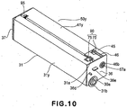
- the bearing unit 45 thus having the first force receiving member 75 and the second force receiving member 70 is fixed to the development accommodating portion 48, and then as shown in Figure 10 , the covering member 46 is fixed so as to cover the bearing unit 45 from an outside in the axial direction of the developing roller 42 of the bearing unit 45.
- the first force receiving member 75 and the second force receiving member 70 are disposed above the cartridge 50y in the state that cartridge 50y is mounted to the main assembly 100 of the apparatus.
- a cartridge tray 13 which is a drawer member.
- the cartridge tray 13 is movable (inserting and drawing) along a rectilinear line which is substantially horizontal (D1, D2 directions) relative to the main assembly 100 of the apparatus. More particularly, the cartridge tray 13 is movable between a mounted position in the main assembly 100 of the apparatus shown in Figure 1 and a drawn-out position outside the main assembly 100 of the apparatus shown in Figure 4 . In the state that cartridge tray 13 is at the drawn-out position, the cartridges 50y, 50m, 50c, 50k are mounted on the cartridge tray 13 by the operator substantially vertically (arrow C) as shown in Figure 4 .
- the cartridges 50y, 50m, 50c, 50k are arranged in parallel with each other such that longitudinal directions (axial directions of the photosensitive drum 30 and the developing roller 42) thereof are substantially perpendicular to the moving direction of the cartridge tray 13.
- the cartridges 50y, 50m, 50c, 50k are entered into the main assembly 100 of the apparatus while being carried on the cartridge tray 13.
- the cartridges 50y, 50m, 50c, 50k are moved keeping a distance (gap f2) ( Figure 5 ) between the intermediary transfer belt 19 provided below them and the photosensitive drum 30.
- the cartridges 50y, 50m, 50c, 50k are positioned in place by the positioning portion 101a provided in the main assembly of the image forming apparatus 100.
- the positioning operation will be described in detail hereinafter. Therefore, the user can mount with certainty the cartridges 50y, 50m, 50c, 50k into the main assembly 100 of the apparatus by entering the cartridge tray 13 and closing the door 12. Therefore, the operationality is improved over the structure with which the cartridges 50y, 50m, 50c, 50k are mounted individually into the main assembly 100 of the apparatus by the user.
- the cartridge tray 13 is supported drawably relative to a tray holding member 14.
- the tray holding member 14 is movable in interrelation with movement of the door 12 (opening and closing member).
- the door 12 is provided on the main assembly 100 of the apparatus and is rotatable about a rotational center 12a.
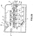
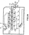
- the door 12 When the cartridge is taken out of the main assembly 100 of the apparatus, the door 12 is moved from the closed position to the open position. With the movement of the door 12, an engaging portion 15 provided on the door 12 moves clockwisely about the rotational center 12a. Then, as shown in Figure 24 , the engaging portion 15 moves from the lower end 14c2 toward the upper end 14c1 in the elongated hole 14c provided in the tray holding member 14. Together with this operation, the engaging portion 15 moves the holding member 14 in the direction z1. At this time, as shown in Figure 25 , the projections 14d1, 14d2 projected from the tray holding member 14 are guided by a guide slot or groove 107 provided in the main assembly 100 of the apparatus.
- the guide groove includes a horizontal portion 107a1, an inclined portion 107a2 continuing with the horizontal portion 107a1 and inclining upwardly and a. horizontal portion 107a3 continuing with the inclined portion 107a2. Therefore, as shown in Figure 24 , when the door 12 is moved to the open position, the projections 14d1, 14d2 are guided along horizontal portion 107a1, the inclined portion 107a2 and the horizontal portion 107a3 in this order. Thus, the tray holding member 14 moves in the direction of z1 and in the direction of an arrow y1 away from the transfer belt 19. In this state, as shown in Figure 25 , the cartridge tray 13 can be drawn toward outside of the main assembly 100 of the apparatus in the direction of an arrow D2 through the opening 80.
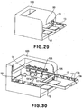
- Figure 30 is a partly broken.perspective view of this state.
- positioning portions 101a for positioning the cartridges 50y, 50m, 50c, 50k in the main assembly 100 of the apparatus.
- the positioning portions 101a are provided for the respective cartridges 50y, 50m, 50c, 50k interposing the transfer belt 19 with respect to the longitudinal direction.
- a first force application member 61 is rotatably supported by the supporting shaft 55 of the main assembly 100 of the apparatus engaged with the supporting hole 61d at a position above the tray holding member 14.
- the first force application member 61 moves with the movement of the door 12 from the open position to the closing position.
- the projected portion 61f provided on the first force application member 61 urges the projection 31a provided on the upper surface portion of the drum frame 34.
- the cartridge 50y is urged in the direction of an arrow P ( Figure 19 ), so that portion to be positioned 31b ( Figure 7 ) provided on the drum unit 31y is abutted to the positioning portion 101a provided in the main assembly 100 of the apparatus by which the cartridge 50y is positioned in place ( Figure 6 ).
- the same operation is carried out adjacent the opposite longitudinal ends. Also, the same operation is carried out for the other cartridges 50m, 50c, 50k.
- the mechanism for movement of the first force application member 61 in interrelation with the movement of the door 12 will be described.
- the first force application member 61 is engaged with a connecting member 62 for interrelation with the movement of the door 12.
- the connecting member 62 includes a supporting hole 62c engaged with the supporting shaft 55, a hole 62a engaged with the projected portion 61f, and a supporting pin 62b engaged with the elongated hole 14b ( Figure 27 , (b)) provided in the tray holding member 14.
- Figure 27 by the movement of the door 12 from the open position to the close position, the tray holding member 14 moves in the direction of the arrow y2 ( Figure 27 ) .
- the supporting pin 62b engaged with the elongated hole 14b also receives the force in the direction of the arrow y2. Therefore, the connecting member 62 rotates in the direction of an arrow Z ( Figure 27 ) about the supporting hole 62c.
- a spring 66 As shown in Figure 19 , between the first force application member 61 and the connecting member 62, there is provided a spring 66.
- the spring 66 is supported by the supporting shaft 55, and is contacted to the projection 62e provided on the connecting member 62 and to the projected portion 61f provided on the first force application member 61.
- the projected portion 61f urges the projection 31a provided on the drum frame 34 in the direction of an arrow P so as to position the cartridges 50y, 50m, 50c, 50k to the positioning portions 101a of the main assembly 100 of the apparatus.
- the projection 31a may be urged directly by the spring 66.
- the structure for the connecting member 62 to interrelate with the movement of the door 12 is same as with Figure 15 to Figure 20 .
- one end 66b of the spring 66 is engaged with the hook 62e provided on the connecting member 62
- the other end 66b of the spring 66 is engaged with the projection 62f provided on the connecting member 62.
- the other end 66b becomes away from the projection 62f and directly urges the projection 31a to position the cartridges 50y, 50m, 50c, 50k to the positioning portion 101a of the main assembly 100 of the apparatus.
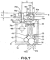
- Figure 5 - Figure 8 are sectional views of the cartridge as seen in the axial direction of the photosensitive drum 30, and Figure 11 - Figure 14 are perspective views as seen from the non-driving side of the cartridge 50y.
- the state shown in Figure 5 corresponds to the state shown in Figure 11 and to the state shown in Figure 15 .
- the state shown in Figure 6 corresponds to the state shown in Figure 12 and to the state shown in Figure 16 .
- the state shown in Figure 7 corresponds to the state shown in Figure 13
- the state of Figure 8 corresponds to the state of Figure 14 .
- the first force application member 61 moves about the supporting shaft 55 from the state of Figures 5 , 11 and 15 to the state of Figures 6 , 12 , 16 .
- the first force application member 61 not only positions the cartridge 50y relative to the main assembly 100 of the apparatus but also acts on the first force receiving member 75 of the cartridge 50y. More particularly, an urging portion 61e of the first force application member 61 abuts the first urged portion of the first force receiving member 75. Thereafter, the first force receiving member 75 urges the cam surface 70c (third urged portion) provided in the second force receiving member 70 by which the second force receiving member 70 is rotated about the shaft 70a.
- the second force receiving member 70 is moved from the stand-by position as shown in Figures 5 , 11 , 15 to an outside of the developing unit 41 of the cartridge 50y, that is, away from the rotation axis 46b of the developing unit 41.
- the projected portion 62 g projected from the connecting member 62 functions as the first force application member 61.
- a driving force from a motor 110 (driving source) provided in the main assembly 100 of the apparatus is transmitted to the gear 112 by way of the gear 111.
- the gear 112 receiving the driving force rotates in the direction of an arrow L to rotate a cam portion 112a provided integrally with the gear 112 in the direction of the arrow L.
- the cam portion 112a is engaged with a shifting force receiving portion 60b provided on the second force application member 60. Therefore, with rotation of the cam portion 112a, the second force application member 60 moves in the direction of an arrow E or B.
- Figure 28 illustrates in (a) the case in which the second force application member 60 moves in the direction of the arrow E and in which the developing roller 42 and the photosensitive drum 30 are still in contact with each other ( Figure 7 ).
- Figure 28 illustrates in (b) the case in which the second force application member 60 moves in the direction of the arrow B and in which the second force receiving member 70 receives a force from the engaging rib 60y.
- the developing unit 41 is rotated (moved) about the rotation axis 46b, so that developing roller 42 and the photosensitive drum 30 become spaced from each other.
- the position of the developing unit 41 at this time is a spaced position.
- the second force application member 60 is provided with an elongated hole portion 60c for permitting movement of a supporting shaft 55 on which the first force application member 61 is provided rotatably. Therefore, even when the second force application member 60 moves in the direction of the arrow B ( Figure 8 ) or in the direction of the arrow E ( Figure 7 ), the second force application member 60 can move without being disturbed by the first force application member 61.
- the second force application member 60 is provided facing the movement path of the cartridges so as to be above the cartridges 50y, 50m, 50c, 50k entering the main assembly 100 of the apparatus on the cartridge tray 13.
- the second force receiving member 70 is kept at the stand-by position ( Figure 15 ). Therefore, the first force application member 61 and the second force application member 60 can be very close to the cartridges 50y, 50m, 50c, 50k as long as they do not interfere therewith, so that wastefull space can be removed. Therefore, the main assembly 100 of the apparatus can be downsized with respect to the vertical direction and the longitudinal direction of the cartridge 50y (axial direction of the photosensitive drum 30).
- the cartridges 50y, 50m, 50c, 50k are mounted from the top to the cartridge tray 13 drawn out to the drawn-out position in the direction of an arrow C.
- the cartridges 50y, 50m, 50c, 50k are passed through the opening 80 into the main assembly 100 of the apparatus.
- the cartridges 50y, 50m, 50c, 50k are inserted into the main assembly 100 of the apparatus in the direction substantially perpendicular to the axial direction of the photosensitive drum 30.
- the cartridge 50y is mounted at the most downstream position in the cartridge tray 13 with respect to the inserting or entering direction.
- the cartridge 50y advances from the upstream side toward the downstream side below the first force application members 61k, 61c, 61m and the engaging ribs 60k, 60c, 60m of the second force application member 60 which are actable on the cartridges 50m, 50c, 50k.
- the cartridge 50m is mounted at the second position from the downstream side on the cartridge tray 13 with respect to the entering direction.
- the cartridge 50m advances from the upstream side toward the downstream side below the first force application members 61k, 61c and the engaging ribs 60k, 60c of the second force application member 60 which are actable on the cartridges 50c, 50k.
- the cartridge 50c is mounted at the third position from the downstream side on the cartridge tray 13 with respect to the entering direction.
- the cartridge 50c passes from the upstream side toward the downstream side below the engaging ribs 60k of the first force application member 61k and the second force application member 60 which are actable on the cartridge 50k.
- the most upstream cartridge 50k on the cartridge tray 13 with respect to the entering direction enters from the upstream side toward the downstream side such that second force receiving member 70 thereof passes below the first force application member 61 actable on the cartridge 50k.
- the first force application member 61 and the second force application member 60 have to be at an upper part so as to avoid interference of the second force receiving member 70 with the first force application member 61 and second force application member 60.
- the first force application member 61 and the second force application member 60 can be disposed close to the cartridges 50y, 50m, 50c, 50k without the necessity of taking into account the degree of projection of the second force receiving member 70. Therefore, the main assembly 100 of the apparatus can be downsized with respect to the vertical direction.
- the positions of the force receiving device 90, the first force application member 61 and the second force application member 60 are such that force receiving device 90 overlaps with the first force application member 61 and the second force application member 60 in the drum axial direction, and therefore, the cartridge can be downsized with respect to the longitudinal direction thereof.
- a gap f1 is maintained between the second force application member 60 and the force receiving device 90 as shown in Figure 5 . Also, a gap f2 is maintained between the photosensitive drum 30 and the transfer belt 19. Therefore, the cartridges 50y, 50m, 50c, 50k can enter without interference with the main assembly 100 of the apparatus.
- the first force application member 61 is moved so that projection 31a provided on the upper surface portion of the drum frame 34 is urged by the projected portion 61f.
- the positioning portions 31b of the cartridges 50y, 50m, 50c, 50k are abutted to the respective positioning portions 101a provided in the main assembly 100 of the apparatus , so that cartridges 50y, 50m, 50c, 50k are positioned to the main assembly 100 of the apparatus.
- the cartridges 50y, 50m, 50c, 50k are prevented from moving in the direction of the an arrow a ( Figure 1 ) in the main assembly 100 of the apparatus by engaging the shaft 36d provided on the covering member 36 shown in Figure 10 with a rotation preventing portion 13a provided on the cartridge tray 13.
- the urging portion 61e of the first force application member 61 contacts and urges the urged portion 75a ( Figure 15 ) of the first force receiving member 75 positioned at the first position ( Figure 15 ). Thereafter, the first force receiving member 75 is moved in the direction of an arrow r to be positioned at the second position ( Figure 16 ).
- the urging portion 75b urges the cam surface 70c of the second force receiving member 70 shown in Figure 15 .
- the second force receiving member 70 rotates about the axis of the shaft 70a from the stand-by position to a position outside the developing unit 41 of the cartridges 50y, 50m, 50c, 50k, that is, in the direction away from the rotation axis 46b of the developing unit 41.
- the upper surface 70b of the second force receiving member 70 interferes with the lower surface of the engaging rib 60y of the second force application member 60 which is placed at the home position, by which the movement of the second force receiving member 70 is regulated by the engaging rib 60y ( Figures 6, 12 ).
- the position of the second force receiving member 70 at this time is called regulating position.
- this position is made the home position for the following reason:
- the state is as shown in Figure 8 until the image forming operation is carried out. More particularly, the second force application member 60 has been moved in the direction of the arrow B, so that engaging rib 60y urges the second force receiving member 70.
- photosensitive drum 30 photosensitive drum 30 the developing roller 42 are spaced from each other.
- cartridges 50y, 50m, 50c, 50k are dismounted from the main assembly 100 of the apparatus.
- the direction (arrow J) of the force received by the first force receiving member 75 from the first force application member 61 is substantially opposite the direction of the force received by the second force receiving member 70 from the second force application member 60.
- the surface of the second force receiving member 70 which receives the force from the second force application member 60 direction faces the direction of entrance of the cartridges 50y, 50m, 50c, 50k into the main assembly 100 of the apparatus.
- the second force application member 60 when the second force application member 60 is moved from the position of Figures 6 , 12 in the direction of the arrow E as shown in Figures 7 , 13 , the second force receiving member 70 moves outwardly of the cartridge 50y to enter the movement path of the engaging rib 60y.
- the position of the second force application member 60 at this time is called projected position.
- the second force application member 60 is projected beyond the above-described stand-by position when it is at the projected position.
- the degree of projection of the second force receiving member 70 at the projected position is larger than the gap fl+f2 in order to engage with the second force application member 60.
- the operation of the second force application member 60 is carried out at the prior to the image formation after cartridges 50y, 50m, 50c, 50k are mounted to the main assembly 100 of the apparatus.
- the second force application member 60 moves in the direction of the arrow B, so that side surface 70d which is the second urged portion of the second force receiving member 70 entering the movement path receives the force from the engaging rib 60y.
- the developing unit 41 rotates (moves) about the rotation axis 46b , so that developing roller 42 is spaced from the photosensitive drum 30 by a gap ⁇ .
- the second force application member 60 receives the force from the second force receiving member 70 in the projected position.
- the distance from the rotation axis 46b of the developing unit 41 can be made large. Therefore, the driving torque required for spacing the developing roller 42 from the photosensitive drum 30 can be made small.
- the elastic portion 75c is in the form of flexible arch configuration. Inside the elastic portion 75c, there is provided a spring 76 which is an elastic member. The spring 76 prevents the elastic portion 75c from flexing beyond necessity and functions to restore the flexed elastic portion 75c.
- the arch configuration of the elastic portion 75c is not inevitable, and the elastic member may be a simple elastic member.
- the developing roller 42 is contacted to the photosensitive drum 30 by moving the second force application member 60 in the direction of the arrow E.
- the second force receiving member 70 is brought into a state of not receiving the force from the engaging rib 60y. Therefore, by the urging force of the spring 95 provided between the developing unit 41 and the drum unit 31, the developing roller 42 and the photosensitive drum 30 are contacted to each other so that cartridges 50y, 50m, 50c, 50k become capable of forming the image.
- the photosensitive drum 30 prior to the contact of the developing roller 42 to the photosensitive drum 30, the photosensitive drum 30 rotates, and the developing roller 42 also receives the driving force from the main assembly 100 of the apparatus and rotates.
- the rotations of the developing roller 42 and the photosensitive drum 30 are stopped.
- the speed difference between the peripheral surfaces of the photosensitive drum 30 and the developing roller 42 is reduced, and therefore, the wearing of the photosensitive drum 30 and the developing roller 42 can be reduced. Therefore, the image quality can be improved.
- a force receiving device 190 comprises a first force receiving member 179 and a second force receiving member 178.
- the.first force application member 165 is provided with a sliding portion 165a (inclined surface)
- the first force receiving member 179 is provided with a sliding portion 179a (inclined surface).
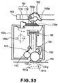
- Figure 33 shows the state before the first force application member 165 moves.
- Figure 34 shows the state in which the second force receiving member 178 is projected from the cartridge 150y by the first force application member 165 moving to abut the first force receiving member 179.
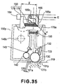
- Figure 35 shows the state after the second force application member 164 moves in the direction of the arrow E.
- the developing unit 41 is rotatable relative to the drum unit 31 in order to contact and space the developing roller 42 and the photosensitive drum 30 relative to each other.
- Figure 36 shows an alternative structure wherein the portion to be guided 544 is in the form of a square pole configuration, and the drum unit 531 is provided with an elongated hole 536a engageable with the portion to be guided 544, wherein the developing unit 541 is slidable relative to the drum unit 531.
- the developing roller 542 is urged by an urging spring (unshown) (elastic member) so as to contact the developing roller 542 to the photosensitive drum.
- the second force application member 560 moves in the direction of the arrow B to act on the second force receiving member 570.
- the developing unit 541 slides in the direction the relative to the drum unit 531 so that developing roller 542 and the photosensitive drum 530 are spaced by the gap g.
- the force receiving device 590 includes the first force receiving member 575 and the second force receiving member 570.
- the first force application member 61 rotates from the position of Figures 6 , 12 to the position of Figures 5 , 11 .
- the first force receiving member 75 is released from the urging force of the first force application member 61 , so that first force receiving member 75 moves from the state shown in Figures 6 , 12 to the state shown in Figures 5 , 11 .
- the second force receiving member 70 becomes free from the urging portion 75b of the first force receiving member 75.
- the second force receiving member 70 also returns to the stand-by position (non-operating position) about the shaft 70a by the force of the spring 73 shown in Figure 19 in the direction of an the arrow A.
- the tray holding member 14 With the movement of the door 12 from the close position to the open position, the tray holding member 14 is raised away from the transfer belt 19 as shown in Figures 3 , 4 . By this, the cartridges 50y, 50m, 50c, 50k are raised, and therefore, the photosensitive drum 30 is separated from the transfer belt 19.
- the second force receiving member 70 for moving the developing unit 41 is constituted such that it projects outwardly from the developing unit 41 when the cartridges 50y, 50m, 50c, 50k are mounted to the main assembly 100 of the apparatus and the door 12 moves to the close position. Therefore, the cartridges 50y, 50m, 50c, 50k can be downsized. In addition, since the mounting is effected when the second force receiving member 70 is at the stand-by position , the space in the main assembly 100 of the apparatus required for the movement of the cartridges 50y, 50m, 50c, 50k may be small.
- the size of the opening 80 may be small, and the first force application member 61 and the second force application member 60 can be close to the cartridges 50y, 50m, 50c, 50k. Therefore, the size of the main assembly 100 of the apparatus can be reduced with respect to the vertical direction.
- the force receiving device 90 is overlapped with the first force application member 61 and the second force application member 60 with respect to the drum axial direction, and therefore, the cartridge can be downsized with respect to the longitudinal direction.
- the second force receiving member 70 can be placed at the stand-by position, and therefore, the second force receiving member 70 is hot easily damaged.
- the cartridges 50y, 50m, 50c, 50k are mounted to the main assembly 100 of the apparatus in the direction substantially perpendicular to the axis of the photosensitive drum 30.
- the cartridges 450y, 450m, 450c, 450k are mounted to the main assembly 401 of the electrophotographic image apparatus (main assembly of the apparatus) in the direction substantially parallel with the axial direction of the electrophotographic photosensitive drum the photosensitive drum) 430.
- the points different from the first embodiment will be described mainly.
- the main assembly 401 of the apparatus is loaded with the cartridges 450y, 450m, 450c, 450k in the direction (arrow K) substantially parallel with the axial direction (longitudinal direction) of the photosensitive drum 430.
- the cartridges 450y, 450m, 450c, 450k are mounted to the mounting member 480c provided in the main assembly 401 of the apparatus, in the direction of the arrow K.
- the cartridges 450y, 450m, 450c, 450k accommodate yellow color, magenta color, cyan color and black color toner particles (developers), respectively.
- the cartridges 450y, 450m, 450c, 450k are each provided with a force receiving device 490 having a first force receiving member 475 and a second force receiving member 470.
- a first force application member 461 and a second force application member 460 actable on the first force receiving member 475 and the second force receiving member 470, respectively.
- the main assembly 401 of the apparatus is provided with an opening 408 for permitting the cartridges 450y, 450m, 450c, 450k to enter the main assembly 401 of the apparatus and a door 412 movable between a close position closing the opening 408 and an open position opening the opening 408.
- the door 412 is rotatable about the rotation axis 412a.
- the mounting member 480 integrally includes holding portions 480c for holding the cartridges 450y, 450m, 450c, 450k, respectively, an operation member 480b for moving the first force application member 461, and a connecting portion 480a for connecting the operation member 480b and the door 412 with each other.
- the connecting portion 480a and the door 412 are connected with each other by engagement between an elongated hole 480 g provided in the connecting portion 480a and a projection 412b provided on the door 412.
- the portion to be positioned 431b provided on the drum unit 431 is abutted to the positioning portion 401a provided in the main assembly 401 of the apparatus by which the cartridges 450y, 450m, 450c, 450k are positioned correctly.
- Each of the cartridges 450y, 450m, 450c, 450k is prevented from movement in the direction of the arrow a in Figure 39 in the main assembly 401 of the apparatus by engaging the shaft 436d provided on the covering member 436 with a rotation preventing portion 485a provided in the main assembly 401 of the apparatus.
- FIG. 40 - Figure 45 the operations of the first force application member 461 will be described. Similarly to the first embodiment, the first force application member 461 is engaged with a connecting member 462 to interrelate with the operation of the operation member 480b.
- the structure of the connecting member 462 is the same as in the first embodiment.
- Figures 40 and 42 , (a) and Figure 43 show the state in which the door 412 is at the open position and in which the operation member 480b takes an upper position.
- Figures 41 and 42 , (b) and Figure 44 show the state in which the door 412 is at the close position.
- the operation member 480b moves down (in the direction of an arrow n).
- a projection 462b provided on the connecting member 462 is in engagement with an elongated hole 480h provided in the mounting member 480. Therefore, with movement of the operation member 480b, the connecting member 462 rotates in the direction of an arrow Q about the rotational center 461d. Similarly to the first embodiment, the first force application member 461 rotates with the rotation of the connecting member 462. When the door 412 is moved from the close position to the open position, the operations are reverse to the above-described operations. The other operations are the same as with the first embodiment.
- the operations of the second force applying portion 460 are the same as with the first embodiment.
- the cartridge 450y includes a photosensitive drum 430, process means actable on the photosensitive drum 430.
- the process means includes a charging roller 432 functioning as charging means for charging electrically the photosensitive drum 430, a developing roller 442 functioning as developing means for developing a latent image formed on the photosensitive drum 430, and/or blade 433 functioning as cleaning means for removing residual toner remaining on the surface of the photosensitive drum 430.
- the cartridge 450y comprises a drum unit 431 and a developing unit 441.
- the structures of the drum unit 431 and the developing unit 441 and the connecting structure between the drum unit 431 and the developing unit 441' are the same as with the first embodiment.
- the cartridge 450y includes a force receiving device 490 for contacting the developing roller 442 and the photosensitive drum 430 to each other and for spacing them from each other.
- the detail structures thereof are the same as with Figures 9 and 15 - 19 .
- the force receiving device 490 of this embodiment comprises a first force receiving member 475, a second force receiving member 470 and a spring which is urging means (unshown).
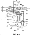
- Figure 49 shows the state after the second force application member 460 moves in the direction of an arrow E from the home position ( Figure 48 ) in which the developing roller 442 and the photosensitive drum 430 are still in contact with each other.
- Figure 50 shows the state after the second force application member 460 moves in the direction of an arrow B in which the developing roller 442 and the photosensitive drum 430 are spaced from each other.
- the second force applying portion 460 is provided with an elongated hole portion 460c for avoiding the rotation axis 461d of the first force application member 461. Even when the second force applying portion 460 moves in the direction of an arrow E or arrow B, the second force applying portion 460 can move without interference with the first force application member 461.
- the first force application member 461 and the second force application member 460 are provided above the cartridges 450y, 450m, 450c, 450k entering the main assembly 401 of the apparatus.
- the second force receiving member 470 is kept in the stand-by position.
- the second force receiving member 470 is projected outwardly of the developing unit 441 when the cartridges 450y, 450m, 450c, 450k are mounted to the main assembly 401 of the apparatus and the door 412 is moved to the close position. Therefore, the cartridges 50y, 50m, 50c, 50k can be downsized Since the cartridges 450y, 450m, 450c, 450k are inserted with the second force receiving members 470 are at the stand-by positions, the space required for entering the cartridges 450y, 450m, 450c, 450k may be small.
- the size of the opening 480 may be small, and the first force application member 461 and the second force application member 460 can be close to the cartridges 450y, 450m, 450c, 450k. Therefore, the main assembly 401 of the apparatus can be downsized with respect to the vertical direction. Since the arrangement is such that force receiving device 90 are overlapped with the first force application member 61 and the second force application member 60 in the drum axial direction as seen in the vertical direction, the cartridge can be downsized in the longitudinal direction.
- the second force receiving member 470 can be placed at the stand-by position, and therefore, the second force receiving member 470 is not easily damaged.
- This embodiment relates to a modification of the force receiving device.
- This embodiment will be described also with a yellow cartridge 250y accommodating a yellow color developer as an exemplary cartridge.
- the developing unit 241 is provided with a force receiving member 277 (force receiving device).
- the force receiving member 277 includes a shaft portion 277c supported rotatably on the developing device frame 248, a first force receiving portion 277a on which the first force application member 261 is actable, and a second force receiving portion 277b on which the second force application member 263 is actable.
- the force receiving member 277 is integrally constituted by the first force receiving portion and the second force receiving portion.
- the spring 298 has one end fixed to the force receiving member 277 and another end fixed to the developing device frame 248. The force receiving member 277 is kept in the state shown in Figure 51 by the spring 298.
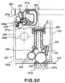
- the second force application member 263 moves in the direction of an arrow B by the driving force from the main assembly of the apparatus to contact to the second force receiving portion 277b of the force receiving member 277. Further, when the second force application member 263 moves in the direction of an arrow B, the developing unit 241 rotates about the connecting portion 246b with the drum unit 231, by which the developing roller 242 is spaced from the electrophotographic photosensitive drum 230 by a gap ⁇ . At this time, as shown in Figure 53 , the portion to be locked 277d of the force receiving member 277 is contacted to the locking portion 248a of the developing device frame 248 to regulate the movement of the force receiving member 277 shown in Figure 52 in the direction of the arrow S.
- the developing unit 241 is rotated relative to the drum unit 31.
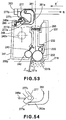
- the first force receiving portion 277a of the force receiving member 277 slides on and deform the free end portion 262a of the first force application member 262 from the shape indicated by a solid lines to the shape indicated by broken lines in Figure 54 .
- the free end portion 262a of the first force application member 262 is elastically deformable.
- the first force receiving portion 277a constitutes a sliding surface slidable relative to the first force application member 262.
- the elastic deformability of the free end portion 262a of the first force application member 262 assures the urging of the force receiving member 277 to the locking portion 248a even when the second force application member 263 moves in the direction of the arrow B in the state of Figure 53 .
- the structures other than the force receiving member 277 are the same as those of the cartridge 50y described in the first embodiment.
- the operations of the first force application member 261 in this embodiment are the same as those of the first force application member 61 in the first embodiment or the first force application member 461 in the second embodiment.
- the number of parts is smaller than the number of parts of the force receiving device 90 of the first embodiment.
- This embodiment relates to a modification of the force receiving device.
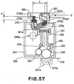
- the developing unit 341 is provided with a force receiving device 370.
- the force receiving device 370 includes a first force receiving member 370a, of second force receiving member 370b, a first spring 370c, and a second spring 370d.
- the force receiving device 370 is movably supported in a guide 341a provided in the developing device frame 348.
- the second spring 370d is provided between a locking portion 341c provided at one end of the guide 341a and a locking portion 370e provided on the second force receiving member 370b.
- the first spring 370c is provided between the first force receiving member 370a and the second force receiving member 370b.
- the second force receiving member 370b When the door (unshown) is at the open position, the second force receiving member 370b is retracted to the position (stand-by position) where the locking portion 370e is contacted to the second locking portion 341b provided in the guide 341a as shown in Figure 55 by the urging force of the second spring 370d. At this time, a gap f1 is provided between the second force receiving member 370b and the second force application member 360 provided in the main assembly side of the apparatus. In other words, since the second force receiving member 370b does not receive a force from the second force application member 360, the photosensitive drum 330 and the developing roller 342 are contacted to each other.
- the first force application member 361 is brought into contact to the first urged portion 370a1 of the first force receiving member 370a.
- the second force receiving member 370b is urged through the spring 370c to move the second force receiving member 370b to an outer of the developing unit 241 (arrow P) .
- the second force application member 360 is contacted by the upper surface 370b1 of the second force receiving member 370b to regulate a further movement.
- the spring 370c elastically deforms, the force receiving device 370 is not damaged even if the first force application member 361 continues pressing against the first force receiving member 370a with the movement of the second force receiving member 370b regulated.
- the position where the first force receiving member 370a is urged by the first force application member 361 is fixed, and the second force receiving member 370b is moved by the movement on the second force application member 360 in the direction of the arrow B shown in Figure 58 . Therefore, the distance I between the first force receiving member 370a and the second force receiving member 370b and the distance II between the first force receiving member 370a and the second force receiving member 370b, satisfy distance I > distance I.
- the change of the distance can be accommodated by the sliding of the spring 370c and the first force application member 361 relative to the first force receiving member 370a.
- the structures other than the force receiving device 370 are the same as those of the cartridge 50y of the first embodiment.
- the operations of the first force application member 361 in this embodiment are the same as those of the first force application member 61 in the first embodiment or the first force application member 461 in the second embodiment.
- This embodiment relates to a modified example of a supporting structure for the force receiving device ( Figures 59, 60 ).
- This embodiment will be described also with a yellow cartridge 650y accommodating a yellow color developer as an exemplary cartridge.
- the cartridge.650y is provided with a force receiving device 690 for contact and spacing between the developing roller 642 and the photosensitive drum 630.
- the force receiving device 690 comprises a first force receiving member 675 and a second force receiving member 670 shown in Figures 59 , 60 , similarly to the first embodiment.
- the first force receiving member 675 is mounted to the drum frame 634 by engagement between the engaging portion 675d provided on the first force receiving member 675 with the guide portion 638 of the drum frame 634.
- the first force receiving member 675 mounted to the drum frame 634 is prevented from disengagement from the drum frame 634 by a regulating portion 639 provided on the drum frame 634.
- a shaft 670a of the second force receiving member 670 is engaged with a guide portion 645a provided on the bearing unit 645.
- the bearing unit 645 including a second force receiving member 670 is fixed to one longitudinal end of the developing device frame 648 and rotatably supports the developing roller 642 having a developing roller gear 669 at the end.
- the bearing unit 645 is provided with a coupling member 667 for receiving the driving force from the driving motor (unshown), and an idler gear 668 for transmitting the deriving force from the coupling member 667 to the developing roller gear 669.
- the covering member 646 is fixed to the longitudinally outside of the bearing unit 645 so as to cover the coupling member 667 and the idler gear 668.
- the covering member 646 is provided with a cylindrical portion 646b which is projected beyond the surface of the covering member 646.
- the coupling member 667 is exposed through an inside opening of the cylindrical portion 646b.
- FIG. 60 shows the cartridge 650y in which the developing unit 641 and the drum unit 631 have been combined with each other.
- the assembling is such that urging portion 675b of the first force receiving member 675 is capable of acting on a cam surface 671 (third urged portion) provided on the second force receiving member 670 , and similarly to the first embodiment, the contacting and spacing can be accomplished between the electrophotographic photosensitive drum 630 and the developing roller 642.
- the similar advantageous effects as with the first embodiment can be provided.
- This embodiment relates to a modification of the force receiving device.
- the developing unit 741 is provided with a force receiving device 790.
- the force receiving device 790 comprises a first force receiving member 775 and a second force receiving member 770.
- the first force receiving member 775 comprises a supporting portion 775c supported rotatably on the developing device frame 748.
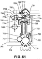
- the second force receiving member 770 is urged normally to provide the state shown in Figure 61 by urging means (unshown) .
- urging means unshown
- the second force receiving member 770 does not receive a force from the second force application member 760
- the photosensitive drum 730 and the developing roller 742 are contacted to each other.
- the first force application member 761 is brought into contact to the first urged portion 775a of the first force receiving member 775 from the top side, as shown in Figure 62 .
- the first force receiving member 775 is rotated about the supporting portion 775c , the urging portion 775b of the first force receiving member 775 acts on-the third urged portion 770b of the second force receiving member 770.
- the second force receiving member 770 moves to an outside (arrow P) of the developing unit 741.
- the upper surface portion 770c of the second force receiving member 770 abuts to the second force application member 760 to prevent a further movement.
- the position of the second force receiving member 770 at this time is called regulating position.
- the force receiving device 790 including the second force application member 760 and the second force receiving member 770 is not damaged. This is because the elastic portion 775d formed by a thin portion provided in the first force receiving member 775 flexes (elastic deformation) as shown in Figure 62 . Therefore, even if the movement of the second force receiving member 770 is regulated, the force receiving device 790 is not damaged.
- the side surface 770d (second urged portion) receives a force from the second force application members 760.
- the developing unit 741 rotates about the connecting portion 746b with the drum unit 731, by which the developing roller 742 is spaced from the electrophotographic photosensitive drum 730 by a gap A.
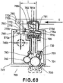
- the position where the first force receiving member 775 is urged by the first force application member 761 is fixed, and the second force receiving member 770 is moved by the movement on the second force application member 770 in the direction of the arrow B shown in Figure 64 .
- the distance I between the first force receiving member 775 and the second force receiving member 770 and the distance II between the first force receiving member 775 and the second force receiving member 770 satisfy distance I > distance II.
- the distance change can be accommodated by the sliding of the first force application member 761 relative to the first force receiving member 775a and the deformation of the elastic portion 775d formed by a thin portion provided on the first force receiving member 775.
- the structures other than the force receiving device 790 are the same as those of the cartridge 50y of the first embodiment.
- the operations of the first force application member 761 in this embodiment are the same as those of the first force application member 61 in the first embodiment or the first force application member 461 in the second embodiment.
- the force receiving device 790 of this embodiment provides the similar advantageous effects as with the first embodiment.
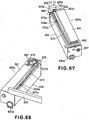
- Figure 65 to Figure 68 show a modified example of the modified example.
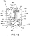
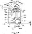
- FIG 65 is a perspective view of a process cartridge 850y as seen from a coupling member 830a side of the photosensitive drum 830 wherein an urging member 820 of the main assembly of the apparatus has moved in the direction of an arrow V (upward) in Figure 67 .
- Figure 66 is a perspective view of the process cartridge 850y as seen from the side opposite from the coupling member 830a of the photosensitive drum 830 in the same state as of Figure 65 .
- Figure 67 is a perspective view of the process cartridge 850y as seen from the coupling member 830a side of the photosensitive drum 830 wherein the urging member 820 of the main assembly of the apparatus has moved in the direction of an arrow U in Figure 67.
- Figure 68 is a perspective view of the process cartridge 850y as seen from the side opposite from the coupling member 830a of the photosensitive drum 830 in the same state as of Figure 67 .
- the main assembly of the apparatus comprises an urging member 820 for urging the cartridge 850y to a positioning portion 801a provided in the main assembly of the apparatus.
- the photosensitive drum 830 is provided with a coupling member 830a for receiving the driving force
- a developing roller is provided with a developing roller gear 869 provided in turn with a coupling member 867 for receiving the driving force
- the urging member 820 urges the cartridge 850y at the longitudinal end opposite from the other longitudinal end where the coupling member 830a and the coupling member 867 are provided.
- the urging member 820 has a guide portion 820a, an urging portion 822 and an urging spring 821. The urging portion 822 is supported by the guide portion 820a for movement toward the cartridge 850y.
- the urging portion 822 is urged by an urging spring 821' in the direction of an arrow U in Figure 67 .
- the operations of the urging member 820 are similar to the operations of the first force application member 61 of the first embodiment, and with the opening operation of the door of the main assembly of the apparatus, the urging member 820 moves in the direction of an arrow V in Figure 67 , and with the closing operation of the door of the main assembly of the apparatus, it moves in the direction of an arrow U in Figure 67 .
- the urging portion 822 is contacted to the cartridge 850y to urge the cartridge 850y by a force of the urging spring 821.
- the cartridge 850y is positioned relative to the main assembly of the image forming apparatus 100 by positioning the projection 831a provided on the drum frame 834 to the positioning portion 801a of the main assembly of the apparatus, similarly to the positioning operation of the cartridge 50y to the main assembly 100 of the apparatus of the first embodiment.
- the developing unit 841 is provided with a force receiving device 890.
- the force receiving device 890 comprises a first force receiving member 875, a second force receiving member 870 and a rod 872.
- the drum frame 834 is provided with a rod 872, and the hole 872a provided in the rod 872 is engaged by the shaft 834a provided on the drum frame 834, and the rod 872 is supported on the drum frame 834 rotatably about the hole 872a.
- the rod 872 is urging in the direction of an arrow S in Figure 65 by a pressure of the spring 840.
- the second force receiving member 870b does not receive a force from the second force application member 860, the photosensitive drum 830 and the developing roller 842 are contacted to each other.
- the urging portion 822 contacts to the cartridge 850y and urges the cartridge 850y by the force of the urging spring 821, as shown in Figure 67 .
- the contact portion 822a of the urging portion 822 relative to the contact portion 822a moves the contact portion 872a of the rod 872 to rotate the rod 872 about the hole 872a.
- an operating portion 872b of the rod 872 moves the first force receiving member 875 in the direction of an arrow W.
- the second force receiving member 870 moves (projects) outwardly of the developing unit 841 of the cartridge 850y from the stand-by position, similarly to the first embodiment.
- the process cartridge of this embodiment has the same structure as the cartridge 50y of the first embodiment.
- the operations of the second force application member 860 of this embodiment are the same as the second force application member 60 of the first embodiment.
- the force receiving device 790 of this embodiment provides the similar advantageous effects as with the first embodiment.
- the process cartridge in which the electrophotographic photosensitive drum and the developing roller are contactable and spaceable relative to each other, and the electrophotographic image forming apparatus to which such a process cartridge is detachably mountable can be downsized.
- a force receiving portion for spacing the developing roller and the electrophotographic photosensitive drum from each other is not easily damaged, when the process cartridge is handled and/or when the process cartridge is transported.
Description
- The present invention relates to a process cartridge in which an electrophotographic photosensitive drum and a developing roller actable on the electrophotographic photosensitive drum which are contactable to each other and spaceable from each other, and an electrophotographic image forming apparatus to which said process cartridge is detachably mountable.
- In an image forming apparatus using an electrophotographic image forming process, a process cartridge type is conventional wherein an electrophotographic photosensitive drum and a developing roller actable on the electrophotographic photosensitive drum are unified into a process cartridge detachably mountable to a main assembly of the image forming apparatus. With the process cartridge type, the maintenance operation of the apparatus can be carried out in effect without the service person. Therefore, the process cartridge type is widely used in the field of electrophotographic image forming apparatus.
- When the image forming operation is carried out, the developing roller is kept urged to the electrophotographic photosensitive drum at a predetermined pressure. In a contact developing system in which a developing roller is contacted to the photosensitive drum during the developing operation, an elastic layer of the developing roller is in contact to the surface of the photosensitive drum at the predetermined pressure.
- Therefore, when the process cartridge is not used for a long term with the process cartridge kept mounted to the main assembly of the image forming apparatus, the elastic layer of the developing roller may be deformed. If this occurs, non-uniformity may result in the formed image. Since the developing roller is contacted to the photosensitive drum, a developer may be depositedofrom the developing roller to the photosensitive drum. Since the photosensitive drum and the developing roller are rotated in contact with each other even when the developing operation is not carried out.
- As a structure for solving the problem, there is provided an image forming apparatus in which when the image forming operation is not carried out, a mechanism act on the process cartridge to space the developing roller from the electrophotographic photosensitive drum (Japanese Laid-open Patent Application
2003-167499 - In the apparatus disclosed in this publication, four process cartridges are demountably mounted to the main assembly of the image forming apparatus. The process cartridge comprises a photosensitive member unit having a photosensitive drum, and a developing unit for supporting the developing roller swingably provided in the photosensitive member unit. By moving a spacing plate provided in the main assembly of the image forming apparatus, a force receiving portion provided in the developing unit receives a force from the spacing plate. By moving the developing unit relative to the photosensitive member unit, the developing roller moves away from the photosensitive drum.
- In the conventional example, the force receiving portion for spacing the developing roller from the photosensitive drum is projected from the outer configuration of the developing unit. Therefore, when the user handles the process cartridge, and/or when the process cartridge is transported, the force receiving portion tends to be damaged. The existence of the force receiving portion may object to downsizing of the process cartridge in which the electrophotographic photosensitive drum and the developing roller are contactable to each other and spaceable from each other and the main assembly of the image forming apparatus to which the process cartridge is detachably mountable.
- Further process cartridges are known from
EP-A-1 519 248 orUS-A-2005/047821 . - Accordingly, it is an object of the present invention to provide a downsized process cartridge in which the electrophotographic photosensitive drum and the developing roller are contactable to each other and spaceable from each other and a downsized electrophotographic image forming apparatus to which the process cartridge is detachably mountable.
- According to the invention, this object is achieved by a process cartridge having the features of claim 1. Advantageous further developments are set out in the dependent claims. An image forming apparatus having such a process cartridge is defined in claim 22.
- According to the present invention, when the process cartridge is handled, or when the process cartridge is transported, the force receiving portion is not damaged.
- The object as well as features and advantages of the present invention will become more apparent upon a consideration of the following description of the preferred embodiments of the present invention taken in conjunction with the accompanying drawings.
-
-
Figure 1 illustrates a general arrangement of an electrophotographic image forming apparatus according to a first embodiment of the present invention. -
Figure 2 is a sectional view of a process cartridge according to the first embodiment of the present invention. -
Figure 3 illustrates a general arrangement of an electrophotographic image forming apparatus according to a first embodiment of the present invention. -
Figure 4 illustrates exchange of a process cartridge according to the first embodiment of the present invention. -
Figure 5 is a sectional view of the process cartridge as seen in the direction of an axial direction of the photosensitive drum according to the first embodiment of the present invention. -
Figure 6 is a sectional view of the process cartridge as seen in the direction of an axial direction of the photosensitive drum according to the first embodiment of the present invention. -
Figure 7 is a sectional view of the process cartridge as seen in the direction of an axial direction of the photosensitive drum according to the first embodiment of the present invention. -
Figure 8 is a sectional view of the process cartridge as seen in the direction of an axial direction of the photosensitive drum according to the first embodiment of the present invention. -
Figure 9 is a perspective view of the process cartridge as seen from drives side according to the first embodiment of the present invention. -
Figure 10 is a perspective view of the process cartridge as seen from the drive side according to the first embodiment the present invention. -
Figure 11 is a perspective view of the process cartridge as seen from a non-driving side according to the first embodiment the present invention. -
Figure 12 is a perspective view of the process cartridge as seen from a non-driving side according to the first embodiment the present invention. -
Figure 13 is a perspective view of the process cartridge as seen from a non-driving side according to the first embodiment the present invention. -
Figure 14 is a perspective view of the process cartridge as seen from a non-driving side according to the first embodiment the present invention. -
Figure 15 is a perspective view showing a force receiving device of the process cartridge according to the first embodiment of the present invention. -
Figure 16 is a perspective view showing a force receiving device of the process cartridge according to the first embodiment of the present invention. -
Figure 17 is a perspective view showing a force receiving device of the process cartridge according to the first embodiment of the present invention. -
Figure 18 is a perspective view showing a force receiving device of the process cartridge according to the first embodiment of the present invention. -
Figure 19 is a perspective view showing a force receiving device of the process cartridge according to the first embodiment of the present invention. -
Figure 20 is a perspective view showing a force receiving device of the process cartridge according to the first embodiment of the present invention. -
Figure 21 is a perspective view showing a force receiving device of the process cartridge according to the first embodiment of the present invention. -
Figure 22 illustrates a process cartridge according to the first embodiment of the present invention wherein a first force receiving member and a second force receiving member are worked on by a first force receiving member and a second force receiving member of the electrophotographic image forming apparatus. -
Figure 23 is a general arrangement of the electrophotographic image forming apparatus according to the first embodiment of the present invention. -
Figure 24 is a general arrangement of the electrophotographic image forming apparatus according to the first embodiment of the present invention. -
Figure 25 is a general arrangement of the electrophotographic image forming apparatus according to the first embodiment of the present invention. -
Figure 26 is a general arrangement of the electrophotographic image forming apparatus according to the first embodiment of the present invention. -
Figure 27 illustrates an operation of a first force application member according to the first embodiment of the present invention. -
Figure 28 illustrates a second force application member operation according to the first embodiment of the present invention. -
Figure 29 is a perspective view of the electrophotographic image forming apparatus according to the first embodiment of the present invention. -
Figure 30 is a perspective view of the electrophotographic image forming apparatus according to the first embodiment of the present invention. -
Figure 31 illustrates exchange of the process cartridge according to the first embodiment of the present invention. -
Figure 32 illustrates exchange of the process cartridge according to the first embodiment of the present invention. -
Figure 33 is a sectional view of the process cartridge as seen in the axial direction of the photosensitive drum according to the first embodiment of the present invention, illustrating an operation of the force receiving member of the process cartridge. -
Figure 34 is a sectional view of the process cartridge as seen in the axial direction of the photosensitive drum according to the first embodiment of the present invention, illustrating an operation of the force receiving member of the process cartridge. -
Figure 35 is a sectional view of the process cartridge as seen in the axial direction of the photosensitive drum according to the first embodiment of the present invention, illustrating an operation of the force receiving member of the process cartridge. -
Figure 36 illustrates a spacing operation in the process cartridge according to the first embodiment of the present invention. -
Figure 37 illustrates a spacing operation in the process cartridge according to the first embodiment of the present invention. -
Figure 38 illustrates a spacing operation in the process cartridge according to the first embodiment of the present invention. -
Figure 39 is a general arrangement of an electrophotographic image forming apparatus according to a second embodiment of the present invention. -
Figure 40 is a general arrangement of the electrophotographic image forming apparatus according to the second embodiment of the present invention. -
Figure 41 is a general arrangement of the electrophotographic image forming apparatus according to the second embodiment of the present invention. -
Figure 42 illustrates an operation of a first force applying operation member of the electrophotographic image forming apparatus according to the second embodiment of the present invention. -
Figure 43 is an illustration of an operation of the first force application member according to the second embodiment of the present invention. -
Figure 44 is an illustration of an operation of the first force application member according to the second embodiment of the present invention. -
Figure 45 is an illustration of an operation of the first force application member according to the second embodiment of the present invention. -
Figure 46 is a sectional view of the process cartridge as seen in the axial direction of the photosensitive drum according to the second embodiment of the present invention. -
Figure 47 illustrates a sectional view of the process cartridge as seen in the axial direction of the photosensitive drum according to the second embodiment of the present invention, illustrating a force receiving device of the process cartridge. -
Figure 48 illustrates a sectional view of the process cartridge as seen in the axial direction of the photosensitive drum according to the second embodiment of the present invention, illustrating a force receiving device of the process cartridge. -
Figure 49 illustrates a sectional view of the process cartridge as seen in the axial direction of the photosensitive drum according to the second embodiment of the present invention, illustrating a force receiving device of the process cartridge. -
Figure 50 illustrates a sectional view of the process cartridge as seen in the axial direction of the photosensitive drum according to the second embodiment of the present invention, illustrating a force receiving device of the process cartridge. -
Figure 51 is a sectional view of a process cartridge according to a third embodiment of the present invention, illustrating an operation of a force receiving member of the process cartridge. -
Figure 52 is a sectional view of the process cartridge according to the third embodiment of the present invention, illustrating the operation of the force receiving member of the process cartridge. -
Figure 53 is a sectional view of the process cartridge according to the third embodiment of the present invention, illustrating the operation of a force receiving member of the process cartridge. -
Figure 54 is a sectional view of the process cartridge according to the third embodiment of the present invention, illustrating the operation of a force receiving member of the process cartridge. -
Figure 55 is a sectional view of a process cartridge as seen in the axial direction of the photosensitive drum according to a fourth embodiment of the present invention, illustrating a force receiving device of the process cartridge. -
Figure 56 is a sectional view of the process cartridge as seen in the axial direction of the photosensitive drum according to the fourth embodiment of the present invention, illustrating a force receiving device of the process cartridge. -
Figure 57 is a sectional view of the process cartridge as seen in the axial direction of the photosensitive drum according to the fourth embodiment of the present invention, illustrating the force receiving device of the process cartridge. -
Figure 58 is a sectional view of the process cartridge as seen in the axial direction of the photosensitive drum according to the fourth embodiment of the present invention, illustrating a force receiving device of the process cartridge. -
Figure 59 is a perspective view of a process cartridge according to a fifth embodiment of the present invention, as seen from a drive side. -
Figure 60 is a perspective view of the process cartridge according to a fifth embodiment of the present invention, as seen from a drive side. -
Figure 61 is a sectional view of a process cartridge according to a sixth embodiment of the present invention. -
Figure 62 is a sectional view of the process cartridge according to the sixth embodiment of the present invention. -
Figure 63 is a sectional view of the process cartridge according to the sixth embodiment of the present invention. -
Figure 64 is a sectional view of the process cartridge according to the sixth embodiment of the present invention. -
Figure 65 is a perspective view of a process cartridge according to a seventh embodiment, illustrating a force receiving device of a process cartridge. -
Figure 66 is a perspective view of the process cartridge according to the seventh embodiment, illustrating the force receiving device of a process cartridge. -
Figure 67 is a perspective view of the process cartridge according to the seventh embodiment, illustrating the force receiving device of a process cartridge. -
Figure 68 is a perspective view of the process cartridge according to the seventh embodiment, illustrating the force receiving device of a process cartridge. - Referring to
Figures 1 - 4 , the process cartridge and the electrophotographic image forming apparatus according to the first embodiment of the present invention. -
Figure 1 shows an electrophotographic image forming apparatus (main assembly of the apparatus) 100 including process cartridges (cartridges) 50y, 50m, 50c, 50k detachably mounted. Thecartridges Figure 2 is a sectional side elevation of the cartridge alone;Figures 3 and4 are illustrations of removing thecartridges main assembly 100 of the apparatus. - As shown in
Figure 1 , themain assembly 100 of the apparatus, the electrophotographic photosensitive drums (photosensitive drums) 30y, 30m, 30c, 30k are exposed to thelaser beams 11 modulated in accordance with the image signal by thelaser scanner 10, so that electrostatic latent images are formed on the surfaces. The electrostatic latent images are developed by developingrollers 42 into toner images (developed images) on the respective surfaces of the photosensitive drums 30. By applying voltages to thetransfer rollers photosensitive drums transfer belt 19. Thereafter, the toner image formed on thetransfer belt 19 is transferred by thetransfer roller 3 onto the recording material P fed by the feeding roller 1 (feeding means). Thereafter, the recording material P is fed to the fixingunit 6 including a driving roller and a fixing roller containing a heater. Here, by applying heat and pressure on the recording material P, the toner image transferred onto the recording material P is fixed. Thereafter, the recording material having the toner image fixed thereon is discharged to a dischargingportion 9 by apair 7 of discharging rollers. - Referring to
Figures 1 ,2 ,5 and22, 29, 30 , thecartridges cartridges cartridge 50y. - The
cartridge 50y includes aphotosensitive drum 30, process means actable on thephotosensitive drum 30. The process means includes a chargingroller 32 functioning as charging means for charging electrically thephotosensitive drum 30, a developingroller 42 functioning as developing means for developing a latent image formed on thephotosensitive drum 30, and/orblade 33 functioning as cleaning means for removing residual toner remaining on the surface of thephotosensitive drum 30. Thecartridge 50y comprises adrum unit 31 and a developingunit 41. - As shown in
Figures 2 ,10 , thedrum unit 31 contains thephotosensitive drum 30, the charging means 32, the cleaning means 33, the residualtoner accommodating portion 35, thedrum frame 34, and the coveringmembers photosensitive drum 30, as shown inFigure 9 , is supported rotatably by a supportingportion 36b of the coveringmember 36. The other longitudinal end of thephotosensitive drum 30, as shown inFigure 11 - Figure 14 , is rotatably supported by a supportingportion 37b of a coveringmember 37. The coveringmembers drum frame 34 at the opposite longitudinal ends of thedrum frame 34. As shown inFigures 9 ,10 , one longitudinal end of thephotosensitive drum 30 is provided with acoupling member 30a for receiving a driving force for rotating thephotosensitive drum 30. Thecoupling member 30a is engaged with first mainassembly coupling member 105 shown inFigures 4 ,30 when thecartridge 50y is mounted to themain assembly 100 of the apparatus. Thephotosensitive drum 30 is rotated in the direction of an arrow u as shown inFigure 2 by a driving force transmitted from a driving motor (unshown) provided in themain assembly 100 of the apparatus to thecoupling member 30a. The charging means 32 is supported on thedrum frame 34 and is rotated by thephotosensitive drum 30 to which the charging means 32 is contacted. The cleaning means 33 is supported by thedrum frame 34 and is contacted to the peripheral surface of thephotosensitive drum 30. The coveringmembers hole portions unit 41. - As shown in
Figure 2 , the developingunit 41 contains the developingroller 42, the developingblade 43, the developingdevice frame 48, the bearingunit 45 and the coveringmember 46. The developingdevice frame 48 comprises atoner accommodating portion 49 for accommodating the toner to be supplied to the developingroller 42, and a developingblade 43 for regulating a layer thickness of the toner of the peripheral surface of the developingroller 42. As shown inFigure 9 , the bearingunit 45 is fixed to the one longitudinal end side of the developingdevice frame 48, and supports rotatably the developing roller. 42 having a developingroller gear 69 at the end thereof. The bearingunit 45 is provided with acoupling member 67, anidler gear 68 for transmitting a driving force to the developingroller gear 69 from thecoupling member 67. The coveringmember 46 is fixed to the longitudinally outside of the bearingunit 45 so as to cover thecoupling member 67 and theidler gear 68. The coveringmember 46 is provided with acylindrical portion 46b which is projected beyond the surface of the coveringmember 46. Thecoupling member 67 is exposed through an inside opening of thecylindrical portion 46b. Here, thecoupling member 67 is engaged with the second mainassembly coupling member 106 shown inFigure 30 to transmit the driving force from the driving motor (unshown) provided in themain assembly 100 of the apparatus when thecartridge 50y is mounted to themain assembly 100 of the apparatus. - As shown in
Figures 9 ,11 to Figure 14 , when the developingunit 41 and thedrum unit 31 are assembled with each other, an outside circumference of thecylindrical portion 46b is engaged with the supportinghole portion 36a at one end side, and the projectedportion 48b provided projected from the developingdevice frame 48 is engaged with the supportinghole portion 37a at the other end side. By doing so, the developingunit 41 is rotatably supported relative to thedrum unit 31. As shown inFigure 2 , the developingunit 41 is urged by the urging spring 95 (elastic member) so that developingroller 42 rotates about thecylindrical portion 46b and the projectedportion 48b to contact to thephotosensitive drum 30. More specifically, the developingunit 41 is urged in the direction of an arrow G by the urging force of the urgingspring 95 so that developingunit 41 receives a moment H about thecylindrical portion 46b and the projectedportion 48b. By this, the developingroller 42 can be contacted to thephotosensitive drum 30 with a predetermined pressure. The position of the developingunit 41 at this time is "contact position". - As shown in
Figure 10 , the urgingspring 95 of this embodiment is provided on the end which is opposite the one longitudinal end provided with thecoupling member 30a for thephotosensitive drum 30 and with thecoupling member 67 for the developingroller gear 69. Because of such a structure, the force g (Figure 6 ) received by the firstforce receiving member 75 of a force receiving device 90 (which will be described hereinafter) which is provided on the one longitudinal end, from the firstforce application member 61, produces a moment about thecylindrical portion 46b in the developingunit 41. In other words, at the one longitudinal end, the moment h thus produced is effective to urge the developingroller 42 to thephotosensitive drum 30 with a predetermined pressure. At the other end, the urgingspring 95 functions to urge the developing droller 42 to thephotosensitive drum 30 with a predetermined pressure. - As shown in
Figure 2 , thecartridge 50y is provided with aforce receiving device 90 for effecting contact and spacing between the developingroller 42 and thephotosensitive drum 30 in themain assembly 100 of the apparatus. As shown inFigures 9 ,15 andFigure 19 , theforce receiving device 90 includes a firstforce receiving member 75, a secondforce receiving member 70 and a spring 73 (urging means). - As shown in
Figure 9 , the firstforce receiving portion 75 is mounted to the bearingunit 45 by engaging an engagingportion 75d of the first force receiving member with aguide portion 45b of the bearingunit 45. On the other hand, the secondforce receiving member 70 is mounted to the bearingunit 45 by engaging ashaft 70a of the secondforce receiving member 70 with theguide portion 45a of the bearingunit 45. The bearingunit 45 thus having the firstforce receiving member 75 and the secondforce receiving member 70 is fixed to thedevelopment accommodating portion 48, and then as shown inFigure 10 , the coveringmember 46 is fixed so as to cover thebearing unit 45 from an outside in the axial direction of the developingroller 42 of the bearingunit 45. The firstforce receiving member 75 and the secondforce receiving member 70 are disposed above thecartridge 50y in the state thatcartridge 50y is mounted to themain assembly 100 of the apparatus. - The operations of the
force receiving device 90 will be described in detail hereinafter. - The description will be made as to a
cartridge tray 13 which is a drawer member. - As shown in
Figure 4 , thecartridge tray 13 is movable (inserting and drawing) along a rectilinear line which is substantially horizontal (D1, D2 directions) relative to themain assembly 100 of the apparatus. More particularly, thecartridge tray 13 is movable between a mounted position in themain assembly 100 of the apparatus shown inFigure 1 and a drawn-out position outside themain assembly 100 of the apparatus shown inFigure 4 . In the state thatcartridge tray 13 is at the drawn-out position, thecartridges cartridge tray 13 by the operator substantially vertically (arrow C) as shown inFigure 4 . Thecartridges photosensitive drum 30 and the developing roller 42) thereof are substantially perpendicular to the moving direction of thecartridge tray 13. Thecartridges main assembly 100 of the apparatus while being carried on thecartridge tray 13. At this time, thecartridges Figure 5 ) between theintermediary transfer belt 19 provided below them and thephotosensitive drum 30. When thecartridge tray 13 is positioned at the mounted position , thecartridges positioning portion 101a provided in the main assembly of theimage forming apparatus 100. The positioning operation will be described in detail hereinafter. Therefore, the user can mount with certainty thecartridges main assembly 100 of the apparatus by entering thecartridge tray 13 and closing thedoor 12. Therefore, the operationality is improved over the structure with which thecartridges main assembly 100 of the apparatus by the user. - Referring to
Figures 23 to 25 and36 to 38 , the operation of thecartridge tray 13 will be described.. - Here, the cartridges are omitted for simplicity of explanation of the operation of the
cartridge tray 13. - The
cartridge tray 13 is supported drawably relative to atray holding member 14. Thetray holding member 14 is movable in interrelation with movement of the door 12 (opening and closing member). Thedoor 12 is provided on themain assembly 100 of the apparatus and is rotatable about arotational center 12a. - When the cartridge is taken out of the
main assembly 100 of the apparatus, thedoor 12 is moved from the closed position to the open position. With the movement of thedoor 12, an engagingportion 15 provided on thedoor 12 moves clockwisely about therotational center 12a. Then, as shown inFigure 24 , the engagingportion 15 moves from the lower end 14c2 toward the upper end 14c1 in theelongated hole 14c provided in thetray holding member 14. Together with this operation, the engagingportion 15 moves the holdingmember 14 in the direction z1. At this time, as shown inFigure 25 , the projections 14d1, 14d2 projected from thetray holding member 14 are guided by a guide slot or groove 107 provided in themain assembly 100 of the apparatus. As shown inFigure 26 , the guide groove includes a horizontal portion 107a1, an inclined portion 107a2 continuing with the horizontal portion 107a1 and inclining upwardly and a. horizontal portion 107a3 continuing with the inclined portion 107a2. Therefore, as shown inFigure 24 , when thedoor 12 is moved to the open position, the projections 14d1, 14d2 are guided along horizontal portion 107a1, the inclined portion 107a2 and the horizontal portion 107a3 in this order. Thus, thetray holding member 14 moves in the direction of z1 and in the direction of an arrow y1 away from thetransfer belt 19. In this state, as shown inFigure 25 , thecartridge tray 13 can be drawn toward outside of themain assembly 100 of the apparatus in the direction of an arrow D2 through theopening 80.Figure 30 is a partly broken.perspective view of this state. - The description will be made as to the case of mounting the cartridge into the
main assembly 100 of the apparatus. In the state thatdoor 12 is at the open position as shown inFigure 25 , thecartridge tray 13 is entered into themain assembly 100 of the apparatus in the direction of the arrow D1 through theopening 80. Thereafter, as shown inFigure 23 , thedoor 12 is moved to the closing position. With the movement of thedoor 12, the engagingportion 15 provided on thedoor 12 moves counterclockwisely about therotational center 12a. Then, as shown inFigure 23 , the engagingportion 15 moves along theelongated hole 14c provided in thetray holding member 14 toward the lower end 14c2 of theelongated hole 14c. Together with this operation, the engagingportion 15 moves the holdingmember 14 in the direction z2. Therefore, as shown inFigure 23 , when thedoor 12 is moved to the closing position, the projections 14d1, 14d2 are guided by the horizontal portion 107a3, the inclined portion 107a2 and the horizontal portion 207a1 in this order. Thus, thetray holding member 14 moves in the direction z2, and moves in the direction of an arrow y2 toward thetransfer belt 19. - Referring to
Figures 5 ,15 andFigures 19 ,27 ,29, 30 , the description will be made as to the positioning of thecartridges main assembly 100 of the apparatus. - As shown in
Figure 30 , there is providedpositioning portions 101a for positioning thecartridges main assembly 100 of the apparatus. Thepositioning portions 101a are provided for therespective cartridges transfer belt 19 with respect to the longitudinal direction. As shown inFigure 27 , (a) andFigure 27 , (b), a firstforce application member 61 is rotatably supported by the supportingshaft 55 of themain assembly 100 of the apparatus engaged with the supportinghole 61d at a position above thetray holding member 14. - As shown in
Figure 27 , (a), andFigure 27 , (b), the firstforce application member 61 moves with the movement of thedoor 12 from the open position to the closing position. As shown inFigure 20 , the projectedportion 61f provided on the firstforce application member 61 urges theprojection 31a provided on the upper surface portion of thedrum frame 34. By this, thecartridge 50y is urged in the direction of an arrow P (Figure 19 ), so that portion to be positioned 31b (Figure 7 ) provided on thedrum unit 31y is abutted to thepositioning portion 101a provided in themain assembly 100 of the apparatus by which thecartridge 50y is positioned in place (Figure 6 ). The same operation is carried out adjacent the opposite longitudinal ends. Also, the same operation is carried out for theother cartridges - The mechanism for movement of the first
force application member 61 in interrelation with the movement of thedoor 12 will be described. The firstforce application member 61 is engaged with a connectingmember 62 for interrelation with the movement of thedoor 12. As shown inFigure 15 to Figure 19 , the connectingmember 62 includes a supportinghole 62c engaged with the supportingshaft 55, ahole 62a engaged with the projectedportion 61f, and a supportingpin 62b engaged with theelongated hole 14b (Figure 27 , (b)) provided in thetray holding member 14. As shown inFigure 27 , by the movement of thedoor 12 from the open position to the close position, thetray holding member 14 moves in the direction of the arrow y2 (Figure 27 ) . By this, the supportingpin 62b engaged with theelongated hole 14b also receives the force in the direction of the arrow y2. Therefore, the connectingmember 62 rotates in the direction of an arrow Z (Figure 27 ) about the supportinghole 62c. As shown inFigure 19 , between the firstforce application member 61 and the connectingmember 62, there is provided aspring 66. Thespring 66 is supported by the supportingshaft 55, and is contacted to theprojection 62e provided on the connectingmember 62 and to the projectedportion 61f provided on the firstforce application member 61. By the urging force of thespring 66, the projectedportion 61f urges theprojection 31a provided on thedrum frame 34 in the direction of an arrow P so as to position thecartridges positioning portions 101a of themain assembly 100 of the apparatus. - As shown in
Figure 21 , theprojection 31a may be urged directly by thespring 66. Thus, the structure for the connectingmember 62 to interrelate with the movement of thedoor 12 is same as withFigure 15 to Figure 20 . When thedoor 12 is at the open position , oneend 66b of thespring 66 is engaged with thehook 62e provided on the connectingmember 62 , and theother end 66b of thespring 66 is engaged with theprojection 62f provided on the connectingmember 62. By thedoor 12 moving from the open position to the close position, theother end 66b becomes away from theprojection 62f and directly urges theprojection 31a to position thecartridges positioning portion 101a of themain assembly 100 of the apparatus. - Referring to
Figure 5 to Figure 8 andFigure 11 to Figure 19 Figure, the description will be made as to the mechanism for operating theforce receiving device 90 provided on thecartridge 50y.Figure 5 - Figure 8 are sectional views of the cartridge as seen in the axial direction of thephotosensitive drum 30, andFigure 11 - Figure 14 are perspective views as seen from the non-driving side of thecartridge 50y. The state shown inFigure 5 corresponds to the state shown inFigure 11 and to the state shown inFigure 15 . The state shown inFigure 6 corresponds to the state shown inFigure 12 and to the state shown inFigure 16 . The state shown inFigure 7 corresponds to the state shown inFigure 13 , and the state ofFigure 8 corresponds to the state ofFigure 14 . - As described hereinbefore, with the closing operation of the
door 12 from the open position, the firstforce application member 61 moves about the supportingshaft 55 from the state ofFigures 5 ,11 and15 to the state ofFigures 6 ,12 ,16 . At this time, the firstforce application member 61 not only positions thecartridge 50y relative to themain assembly 100 of the apparatus but also acts on the firstforce receiving member 75 of thecartridge 50y. More particularly, an urgingportion 61e of the firstforce application member 61 abuts the first urged portion of the firstforce receiving member 75. Thereafter, the firstforce receiving member 75 urges thecam surface 70c (third urged portion) provided in the secondforce receiving member 70 by which the secondforce receiving member 70 is rotated about theshaft 70a. Then, the secondforce receiving member 70 is moved from the stand-by position as shown inFigures 5 ,11 ,15 to an outside of the developingunit 41 of thecartridge 50y, that is, away from therotation axis 46b of the developingunit 41. With the structure shown inFigure 21 , the projected portion 62 g projected from the connectingmember 62 functions as the firstforce application member 61. - Referring to
Figure 28 , the description will be made as to the operation of the secondforce applying portion 60. - A driving force from a motor 110 (driving source) provided in the
main assembly 100 of the apparatus is transmitted to thegear 112 by way of thegear 111. Thegear 112 receiving the driving force rotates in the direction of an arrow L to rotate acam portion 112a provided integrally with thegear 112 in the direction of the arrow L. Thecam portion 112a is engaged with a shiftingforce receiving portion 60b provided on the secondforce application member 60. Therefore, with rotation of thecam portion 112a, the secondforce application member 60 moves in the direction of an arrow E or B. -
Figure 28 illustrates in (a) the case in which the secondforce application member 60 moves in the direction of the arrow E and in which the developingroller 42 and thephotosensitive drum 30 are still in contact with each other (Figure 7 ).Figure 28 illustrates in (b) the case in which the secondforce application member 60 moves in the direction of the arrow B and in which the secondforce receiving member 70 receives a force from the engagingrib 60y. By doing so, the developingunit 41 is rotated (moved) about therotation axis 46b, so that developingroller 42 and thephotosensitive drum 30 become spaced from each other. The position of the developingunit 41 at this time is a spaced position. - As shown in
Figure 15 , the secondforce application member 60 is provided with anelongated hole portion 60c for permitting movement of a supportingshaft 55 on which the firstforce application member 61 is provided rotatably. Therefore, even when the secondforce application member 60 moves in the direction of the arrow B (Figure 8 ) or in the direction of the arrow E (Figure 7 ), the secondforce application member 60 can move without being disturbed by the firstforce application member 61. Similarly to the firstforce application member 61, the secondforce application member 60 is provided facing the movement path of the cartridges so as to be above thecartridges main assembly 100 of the apparatus on thecartridge tray 13. In the step of advancement of thecartridges main assembly 100 of the apparatus, the secondforce receiving member 70 is kept at the stand-by position (Figure 15 ). Therefore, the firstforce application member 61 and the secondforce application member 60 can be very close to thecartridges main assembly 100 of the apparatus can be downsized with respect to the vertical direction and the longitudinal direction of thecartridge 50y (axial direction of the photosensitive drum 30). - The operation will be described hereinafter in detail.
- The description will be made as to the series of operations from the mounting of the
cartridges main assembly 100 of the apparatus to the spacing of the developingroller 42 from thephotosensitive drum 30. - As shown in
Figure 4 , thecartridges cartridge tray 13 drawn out to the drawn-out position in the direction of an arrow C. - By moving the
cartridge tray 13 in the direction of the arrow D1, thecartridges opening 80 into themain assembly 100 of the apparatus. Thus, in this embodiment, thecartridges main assembly 100 of the apparatus in the direction substantially perpendicular to the axial direction of thephotosensitive drum 30. - As shown in
Figures 31, 32 , thecartridge 50y is mounted at the most downstream position in thecartridge tray 13 with respect to the inserting or entering direction. Thecartridge 50y advances from the upstream side toward the downstream side below the firstforce application members engaging ribs force application member 60 which are actable on thecartridges - The
cartridge 50m is mounted at the second position from the downstream side on thecartridge tray 13 with respect to the entering direction. Thecartridge 50m advances from the upstream side toward the downstream side below the firstforce application members engaging ribs force application member 60 which are actable on thecartridges - The
cartridge 50c is mounted at the third position from the downstream side on thecartridge tray 13 with respect to the entering direction. Thecartridge 50c passes from the upstream side toward the downstream side below the engagingribs 60k of the firstforce application member 61k and the secondforce application member 60 which are actable on thecartridge 50k. - The most
upstream cartridge 50k on thecartridge tray 13 with respect to the entering direction enters from the upstream side toward the downstream side such that secondforce receiving member 70 thereof passes below the firstforce application member 61 actable on thecartridge 50k. - The passing of the second
force receiving member 70 below the firstforce application member 61k from the upstream side toward the downstream side is the same with respect to thecartridges - That is, when the process cartridge is inserted with the second
force receiving member 70 projected, the firstforce application member 61 and the secondforce application member 60 have to be at an upper part so as to avoid interference of the secondforce receiving member 70 with the firstforce application member 61 and secondforce application member 60. However, if the secondforce receiving member 70 is at the stand-by position , the firstforce application member 61 and the secondforce application member 60 can be disposed close to thecartridges force receiving member 70. Therefore, themain assembly 100 of the apparatus can be downsized with respect to the vertical direction. In addition, as shown inFigures 31, 32 , the positions of theforce receiving device 90, the firstforce application member 61 and the secondforce application member 60 are such thatforce receiving device 90 overlaps with the firstforce application member 61 and the secondforce application member 60 in the drum axial direction, and therefore, the cartridge can be downsized with respect to the longitudinal direction thereof. - When the
cartridge tray 13 is inserted into themain assembly 100 of the apparatus, a gap f1 is maintained between the secondforce application member 60 and theforce receiving device 90 as shown inFigure 5 . Also, a gap f2 is maintained between thephotosensitive drum 30 and thetransfer belt 19. Therefore, thecartridges main assembly 100 of the apparatus. - Thereafter, as shown in
Figure 23 , by moving thedoor 12 to the close position, thetray holding member 14 moves in the direction of approaching to the transfer belt 19 (arrow y2) . A vertical component of the movement distance in the direction of an arrow y2 is f2. By doing so, as shown inFigure 6 , thecartridges photosensitive drum 30 is brought into contact to the surface of thetransfer belt 19. In this state, the gap f1 between theforce receiving device 90 and the second force applicationmember engaging portion 60 expands to f1+f2. - In addition, by moving the
door 12 to the close position, the firstforce application member 61 is moved so thatprojection 31a provided on the upper surface portion of thedrum frame 34 is urged by the projectedportion 61f. By this, as shown inFigure 6 , the positioningportions 31b of thecartridges respective positioning portions 101a provided in themain assembly 100 of the apparatus , so thatcartridges main assembly 100 of the apparatus. - The
cartridges Figure 1 ) in themain assembly 100 of the apparatus by engaging theshaft 36d provided on the coveringmember 36 shown inFigure 10 with arotation preventing portion 13a provided on thecartridge tray 13. - The urging
portion 61e of the firstforce application member 61 contacts and urges the urgedportion 75a (Figure 15 ) of the firstforce receiving member 75 positioned at the first position (Figure 15 ). Thereafter, the firstforce receiving member 75 is moved in the direction of an arrow r to be positioned at the second position (Figure 16 ). - At the second position, the urging
portion 75b urges thecam surface 70c of the secondforce receiving member 70 shown inFigure 15 . By doing so, the secondforce receiving member 70 rotates about the axis of theshaft 70a from the stand-by position to a position outside the developingunit 41 of thecartridges rotation axis 46b of the developingunit 41. - However, at this time, the
upper surface 70b of the secondforce receiving member 70 interferes with the lower surface of theengaging rib 60y of the secondforce application member 60 which is placed at the home position, by which the movement of the secondforce receiving member 70 is regulated by the engagingrib 60y (Figures 6, 12 ). The position of the secondforce receiving member 70 at this time is called regulating position. - Here, this position is made the home position for the following reason: After the
cartridges main assembly 100 of the apparatus, the state is as shown inFigure 8 until the image forming operation is carried out. More particularly, the secondforce application member 60 has been moved in the direction of the arrow B, so that engagingrib 60y urges the secondforce receiving member 70. In this state,photosensitive drum 30photosensitive drum 30 the developingroller 42 are spaced from each other. In the state ofFigure 8 ,cartridges main assembly 100 of the apparatus. Thereafter, whencartridges main assembly 100 of the apparatus again, the secondforce application member 60 is at the position shown inFigure 8 , and therefore, when the secondforce receiving member 70 moves from the stand-by position, it is contacted to therib 60y. - As shown in
Figure 8 , the direction (arrow J) of the force received by the firstforce receiving member 75 from the firstforce application member 61 is substantially opposite the direction of the force received by the secondforce receiving member 70 from the secondforce application member 60. The surface of the secondforce receiving member 70 which receives the force from the secondforce application member 60 direction faces the direction of entrance of thecartridges main assembly 100 of the apparatus. By selecting the direction of the receiving force, when the secondforce receiving member 70 receives the force from the secondforce application member 60, the developingunit 41 can be efficiently moved relative to thedrum unit 31 with certainty. Furthermore, the state thatphotosensitive drum 30 and the developingroller 42 are spaced can be maintained stably. - However, even when the movement of the second
force receiving member 70 is limited by the engagingrib 60y, theforce receiving device 90 including the secondforce application member 60 and the secondforce receiving member 70 is not damaged. As shown inFigure 22 , (a), since the movement of the secondforce receiving member 70 is regulated, the movement of the urgingportion 75b for urging thecam surface 70c is also regulated. Even if the urgingportion 61e of the firstforce application member 61 further urges the urgedportion 75a, anelastic portion 75c in the form of arch provided on the firstforce receiving member 75 flexes (elastic deformation). Therefore, even if the movement of the secondforce receiving member 70 is regulated, theforce receiving device 90 is not damaged. - And, when the second
force application member 60 is moved from the position ofFigures 6 ,12 in the direction of the arrow E as shown inFigures 7 ,13 , the secondforce receiving member 70 moves outwardly of thecartridge 50y to enter the movement path of theengaging rib 60y. The position of the secondforce application member 60 at this time is called projected position. Thus, the secondforce application member 60 is projected beyond the above-described stand-by position when it is at the projected position. The degree of projection of the secondforce receiving member 70 at the projected position is larger than the gap fl+f2 in order to engage with the secondforce application member 60. The operation of the secondforce application member 60 is carried out at the prior to the image formation aftercartridges main assembly 100 of the apparatus. - Then, as shown in
Figures 8 ,14 , the secondforce application member 60 moves in the direction of the arrow B, so thatside surface 70d which is the second urged portion of the secondforce receiving member 70 entering the movement path receives the force from the engagingrib 60y. By doing so, the developingunit 41 rotates (moves) about therotation axis 46b , so that developingroller 42 is spaced from thephotosensitive drum 30 by a gap α. The secondforce application member 60 receives the force from the secondforce receiving member 70 in the projected position. Thus, as compared to a structure in which the second force receiving member moves toward the process cartridge and engages with the developing unit to effect the developing device spacing, the distance from therotation axis 46b of the developingunit 41 can be made large. Therefore, the driving torque required for spacing the developingroller 42 from thephotosensitive drum 30 can be made small. - In addition, by the movement of the second
force application member 60 in the direction of the arrow B, the position where the firstforce receiving member 75 is pushed by the firstforce application member 61 and the position where the secondforce receiving member 70 receives the force from the engagingrib 60y change with respect to the horizontal direction. In other words, the relation between a distance I shown inFigure 7 and a distance II shown inFigure 8 is distance I > distance II. The change of the distance is accommodated by theelastic portion 75c provided on the firstforce receiving member 75. As shown inFigure 22 , (a), theelastic portion 75c is in the form of flexible arch configuration. Inside theelastic portion 75c, there is provided aspring 76 which is an elastic member. Thespring 76 prevents theelastic portion 75c from flexing beyond necessity and functions to restore the flexedelastic portion 75c. The arch configuration of theelastic portion 75c is not inevitable, and the elastic member may be a simple elastic member. - In order to effect the image forming operation, the developing
roller 42 is contacted to thephotosensitive drum 30 by moving the secondforce application member 60 in the direction of the arrow E. By this, as shown inFigures 7 ,13 , the secondforce receiving member 70 is brought into a state of not receiving the force from the engagingrib 60y. Therefore, by the urging force of thespring 95 provided between the developingunit 41 and thedrum unit 31, the developingroller 42 and thephotosensitive drum 30 are contacted to each other so thatcartridges roller 42 to thephotosensitive drum 30, thephotosensitive drum 30 rotates, and the developingroller 42 also receives the driving force from themain assembly 100 of the apparatus and rotates. This is accomplished by providing thecoupling portion 67a co-axially with thecylindrical portion 46b so that even if the developingunit 41 moves about thecylindrical portion 46b, the position of thecoupling portion 67a does not change. Thus, thephotosensitive drum 30 and the developingroller 42 are rotated before the developingroller 42 and thephotosensitive drum 30 are contacted to each other. Therefore, when the developingroller 42 is brought into contact to thephotosensitive drum 30, the speed difference between the peripheral surfaces of thephotosensitive drum 30 and the developingroller 42 can be made small, and therefore, wearing of thephotosensitive drum 30 and the developingroller 42 can be reduced. When the image formation is completed, the developingroller 42 and thephotosensitive drum 30 are spaced from each other by moving the secondforce application member 60 in the direction of the arrow B, as described hereinbefore. After the spacing, the rotations of the developingroller 42 and thephotosensitive drum 30 are stopped. Thus, the speed difference between the peripheral surfaces of thephotosensitive drum 30 and the developingroller 42 is reduced, and therefore, the wearing of thephotosensitive drum 30 and the developingroller 42 can be reduced. Therefore, the image quality can be improved. - The elastic portion can be replaced with the structure shown in
Figures 33 ,34 ,35 . Here, aforce receiving device 190 comprises a firstforce receiving member 179 and a secondforce receiving member 178. As shown inFigures 34 ,35 , the.firstforce application member 165 is provided with a slidingportion 165a (inclined surface), and the firstforce receiving member 179 is provided with a slidingportion 179a (inclined surface).Figure 33 shows the state before the firstforce application member 165 moves.Figure 34 shows the state in which the secondforce receiving member 178 is projected from thecartridge 150y by the firstforce application member 165 moving to abut the firstforce receiving member 179.Figure 35 shows the state after the secondforce application member 164 moves in the direction of the arrow E. - The change from I to II of the distance between the first
force receiving member 179 and the secondforce receiving member 178 shown inFigures 34 ,35 is permitted by the slidability between the slidingportion 179a and the slidingportion 165a and by the movability of the firstforce receiving member 179 in the direction of an arrow F shown inFigure 35 . - In the
cartridge 50y used for the description of this embodiment, the developingunit 41 is rotatable relative to thedrum unit 31 in order to contact and space the developingroller 42 and thephotosensitive drum 30 relative to each other. However,Figure 36 shows an alternative structure wherein the portion to be guided 544 is in the form of a square pole configuration, and thedrum unit 531 is provided with anelongated hole 536a engageable with the portion to be guided 544, wherein the developingunit 541 is slidable relative to thedrum unit 531. - More particularly, as shown in
Figure 37 , when the secondforce application member 560 does not act on the secondforce receiving member 570 , the developingroller 542 is urged by an urging spring (unshown) (elastic member) so as to contact the developingroller 542 to the photosensitive drum. Then, as shown inFigure 38 , the secondforce application member 560 moves in the direction of the arrow B to act on the secondforce receiving member 570. By this, the developingunit 541 slides in the direction the relative to thedrum unit 531 so that developingroller 542 and thephotosensitive drum 530 are spaced by the gap g. Similarly to the first embodiment, theforce receiving device 590 includes the firstforce receiving member 575 and the secondforce receiving member 570. - The description will be made as to the operation for taking the
cartridges main assembly 100 of the apparatus. - With the movement of the
door 12 from the close position to the open position, the firstforce application member 61 rotates from the position ofFigures 6 ,12 to the position ofFigures 5 ,11 . By this, the firstforce receiving member 75 is released from the urging force of the firstforce application member 61 , so that firstforce receiving member 75 moves from the state shown inFigures 6 ,12 to the state shown inFigures 5 ,11 . More particularly, the secondforce receiving member 70 becomes free from the urgingportion 75b of the firstforce receiving member 75. As shown inFigure 5 , the secondforce receiving member 70 also returns to the stand-by position (non-operating position) about theshaft 70a by the force of thespring 73 shown inFigure 19 in the direction of an the arrow A. - With the movement of the
door 12 from the close position to the open position, thetray holding member 14 is raised away from thetransfer belt 19 as shown inFigures 3 ,4 . By this, thecartridges photosensitive drum 30 is separated from thetransfer belt 19. - As described in the foregoing, the second
force receiving member 70 for moving the developingunit 41 is constituted such that it projects outwardly from the developingunit 41 when thecartridges main assembly 100 of the apparatus and thedoor 12 moves to the close position. Therefore, thecartridges force receiving member 70 is at the stand-by position , the space in themain assembly 100 of the apparatus required for the movement of thecartridges opening 80 may be small, and the firstforce application member 61 and the secondforce application member 60 can be close to thecartridges main assembly 100 of the apparatus can be reduced with respect to the vertical direction. In addition, as seen in the vertical direction of themain assembly 100 of the apparatus, as shown inFigures 31, 32 , theforce receiving device 90 is overlapped with the firstforce application member 61 and the secondforce application member 60 with respect to the drum axial direction, and therefore, the cartridge can be downsized with respect to the longitudinal direction. - When the
cartridges force receiving member 70 can be placed at the stand-by position, and therefore, the secondforce receiving member 70 is hot easily damaged. - In the first embodiment, the
cartridges main assembly 100 of the apparatus in the direction substantially perpendicular to the axis of thephotosensitive drum 30. In Embodiment 2, thecartridges main assembly 401 of the electrophotographic image apparatus (main assembly of the apparatus) in the direction substantially parallel with the axial direction of the electrophotographic photosensitive drum the photosensitive drum) 430. In the following description, the points different from the first embodiment will be described mainly. - As shown in
Figure 39 Figures 41 , themain assembly 401 of the apparatus is loaded with thecartridges photosensitive drum 430. In this embodiment, thecartridges member 480c provided in themain assembly 401 of the apparatus, in the direction of the arrow K. Thecartridges - The
cartridges force receiving device 490 having a firstforce receiving member 475 and a secondforce receiving member 470. At the rear side of themain assembly 401 of the apparatus with respect to the cartridge entering direction, there are provided a firstforce application member 461 and a secondforce application member 460 actable on the firstforce receiving member 475 and the secondforce receiving member 470, respectively. As shown inFigure 42 , themain assembly 401 of the apparatus is provided with anopening 408 for permitting thecartridges main assembly 401 of the apparatus and adoor 412 movable between a close position closing theopening 408 and an open position opening theopening 408. Thedoor 412 is rotatable about therotation axis 412a. As shown inFigure 45 , the mountingmember 480 integrally includes holdingportions 480c for holding thecartridges operation member 480b for moving the firstforce application member 461, and a connectingportion 480a for connecting theoperation member 480b and thedoor 412 with each other. As shown inFigure 42 , the connectingportion 480a and thedoor 412 are connected with each other by engagement between anelongated hole 480 g provided in the connectingportion 480a and aprojection 412b provided on thedoor 412. - Therefore, with movement of the
door 412 from the open position to the close position in the direction of an arrow m,projections portion 480a move alongguide grooves main assembly 401 of the apparatus as shown inFigure 42 . Thus, a holdingportion 480c integral with theoperation member 480b moves in the direction of an arrow n. Thus, thephotosensitive drums 430 of thecartridges portion 480c are moved from the positions spaced from thetransfer belt 419 shown inFigure 47 to the position contacting to thetransfer belt 419 shown inFigure 48 . Simultaneously, the portion to be positioned 431b provided on thedrum unit 431 is abutted to thepositioning portion 401a provided in themain assembly 401 of the apparatus by which thecartridges - Each of the
cartridges Figure 39 in themain assembly 401 of the apparatus by engaging the shaft 436d provided on the covering member 436 with arotation preventing portion 485a provided in themain assembly 401 of the apparatus. - When the
cartridges main assembly 401 of the apparatus, the operations are reverse to the mounting operations. - Referring to
Figure 40 - Figure 45 , the operations of the firstforce application member 461 will be described. Similarly to the first embodiment, the firstforce application member 461 is engaged with a connectingmember 462 to interrelate with the operation of theoperation member 480b. The structure of the connectingmember 462 is the same as in the first embodiment.Figures 40 and42 , (a) andFigure 43 show the state in which thedoor 412 is at the open position and in which theoperation member 480b takes an upper position.Figures 41 and42 , (b) andFigure 44 show the state in which thedoor 412 is at the close position. When thedoor 412 is closed, theoperation member 480b moves down (in the direction of an arrow n). As shown inFigures 43, 44 , aprojection 462b provided on the connectingmember 462 is in engagement with anelongated hole 480h provided in the mountingmember 480. Therefore, with movement of theoperation member 480b, the connectingmember 462 rotates in the direction of an arrow Q about therotational center 461d. Similarly to the first embodiment, the firstforce application member 461 rotates with the rotation of the connectingmember 462. When thedoor 412 is moved from the close position to the open position, the operations are reverse to the above-described operations. The other operations are the same as with the first embodiment. - The operations of the second
force applying portion 460 are the same as with the first embodiment. - The description will be made as to the structure of the process cartridge of this embodiment. The structures of the
cartridges cartridge 450y referring toFigure 46 . - The
cartridge 450y includes aphotosensitive drum 430, process means actable on thephotosensitive drum 430. The process means includes a chargingroller 432 functioning as charging means for charging electrically thephotosensitive drum 430, a developingroller 442 functioning as developing means for developing a latent image formed on thephotosensitive drum 430, and/orblade 433 functioning as cleaning means for removing residual toner remaining on the surface of thephotosensitive drum 430. Thecartridge 450y comprises adrum unit 431 and a developingunit 441. - The structures of the
drum unit 431 and the developingunit 441 and the connecting structure between thedrum unit 431 and the developing unit 441' are the same as with the first embodiment. - Similarly to the first embodiment, as shown in
Figure 47 , thecartridge 450y includes aforce receiving device 490 for contacting the developingroller 442 and thephotosensitive drum 430 to each other and for spacing them from each other. The detail structures thereof are the same as withFigures 9 and15 - 19 . As shown inFigure 47 , theforce receiving device 490 of this embodiment comprises a firstforce receiving member 475, a secondforce receiving member 470 and a spring which is urging means (unshown). -
Figure 49 shows the state after the secondforce application member 460 moves in the direction of an arrow E from the home position (Figure 48 ) in which the developingroller 442 and thephotosensitive drum 430 are still in contact with each other.Figure 50 . shows the state after the secondforce application member 460 moves in the direction of an arrow B in which the developingroller 442 and thephotosensitive drum 430 are spaced from each other. Similarly to the first embodiment, the secondforce applying portion 460 is provided with anelongated hole portion 460c for avoiding therotation axis 461d of the firstforce application member 461. Even when the secondforce applying portion 460 moves in the direction of an arrow E or arrow B, the secondforce applying portion 460 can move without interference with the firstforce application member 461. - The first
force application member 461 and the secondforce application member 460, as shown inFigures 39 ,40 , are provided above thecartridges main assembly 401 of the apparatus. When thecartridges main assembly 401 of the apparatus, the secondforce receiving member 470 is kept in the stand-by position. - Also in this embodiment, the second
force receiving member 470 is projected outwardly of the developingunit 441 when thecartridges main assembly 401 of the apparatus and thedoor 412 is moved to the close position. Therefore, thecartridges cartridges force receiving members 470 are at the stand-by positions, the space required for entering thecartridges opening 480 may be small, and the firstforce application member 461 and the secondforce application member 460 can be close to thecartridges main assembly 401 of the apparatus can be downsized with respect to the vertical direction. Since the arrangement is such thatforce receiving device 90 are overlapped with the firstforce application member 61 and the secondforce application member 60 in the drum axial direction as seen in the vertical direction, the cartridge can be downsized in the longitudinal direction. - When the
cartridges force receiving member 470 can be placed at the stand-by position, and therefore, the secondforce receiving member 470 is not easily damaged. - This embodiment relates to a modification of the force receiving device.
- This embodiment will be described also with a
yellow cartridge 250y accommodating a yellow color developer as an exemplary cartridge. - As shown in
Figure 51 - Figure 54 , the developingunit 241 is provided with a force receiving member 277 (force receiving device). - The
force receiving member 277 includes ashaft portion 277c supported rotatably on the developingdevice frame 248, a firstforce receiving portion 277a on which the firstforce application member 261 is actable, and a secondforce receiving portion 277b on which the secondforce application member 263 is actable. Theforce receiving member 277 is integrally constituted by the first force receiving portion and the second force receiving portion. Thespring 298 has one end fixed to theforce receiving member 277 and another end fixed to the developingdevice frame 248. Theforce receiving member 277 is kept in the state shown inFigure 51 by thespring 298. - As shown in
Figure 52 , similarly to the first embodiment, by movement of the door (unshown) from the open position to the close position, the firstforce application member 262 is contacted to the firstforce receiving portion 277a of theforce receiving member 277. By doing so, theforce receiving member 277 rotates in the direction of an arrow S shown inFigure 52 about theshaft 277c. The secondforce receiving portion 277b of theforce receiving member 277 moves outwardly of the developingunit 241. - Thereafter, as shown in
Figure 53 , the secondforce application member 263 moves in the direction of an arrow B by the driving force from the main assembly of the apparatus to contact to the secondforce receiving portion 277b of theforce receiving member 277. Further, when the secondforce application member 263 moves in the direction of an arrow B, the developingunit 241 rotates about the connectingportion 246b with thedrum unit 231, by which the developingroller 242 is spaced from the electrophotographicphotosensitive drum 230 by a gap γ. At this time, as shown inFigure 53 , the portion to be locked 277d of theforce receiving member 277 is contacted to the lockingportion 248a of the developingdevice frame 248 to regulate the movement of theforce receiving member 277 shown inFigure 52 in the direction of the arrow S. Therefore, by movement of the secondforce application member 263 in the direction of the arrow E, the developingunit 241 is rotated relative to thedrum unit 31. By the movement of the secondforce application member 263 in the direction of the arrow B, the firstforce receiving portion 277a of theforce receiving member 277 slides on and deform thefree end portion 262a of the firstforce application member 262 from the shape indicated by a solid lines to the shape indicated by broken lines inFigure 54 . To accomplish this, thefree end portion 262a of the firstforce application member 262 is elastically deformable. In addition, the firstforce receiving portion 277a constitutes a sliding surface slidable relative to the firstforce application member 262. - The elastic deformability of the
free end portion 262a of the firstforce application member 262 assures the urging of theforce receiving member 277 to the lockingportion 248a even when the secondforce application member 263 moves in the direction of the arrow B in the state ofFigure 53 . - As regards the contact between the developing
roller 242 and thephotosensitive drum 230, by the movement of the secondforce application member 263 in the direction of the arrow E inFigure 53 from the state shown inFigure 53 , the movement to the secondforce receiving member 277 by the second force application,member 263 is permitted. By the urging force of thespring 295, the developingunit 241 is rotated to contact the developingroller 242 to thephotosensitive drum 230. - In this embodiment, the structures other than the
force receiving member 277 are the same as those of thecartridge 50y described in the first embodiment. The operations of the firstforce application member 261 in this embodiment are the same as those of the firstforce application member 61 in the first embodiment or the firstforce application member 461 in the second embodiment. - As described in the foregoing, in the force receiving device of this embodiment, the number of parts is smaller than the number of parts of the
force receiving device 90 of the first embodiment. - This embodiment relates to a modification of the force receiving device.
- This embodiment will be described also with a
yellow cartridge 250y accommodating a yellow color developer as an exemplary cartridge. As shown in (Figure 55 - Figure 58 , the developingunit 341 is provided with aforce receiving device 370. Theforce receiving device 370 includes a firstforce receiving member 370a, of secondforce receiving member 370b, afirst spring 370c, and asecond spring 370d. Theforce receiving device 370 is movably supported in aguide 341a provided in the developingdevice frame 348. Thesecond spring 370d is provided between a lockingportion 341c provided at one end of theguide 341a and a lockingportion 370e provided on the secondforce receiving member 370b. Thefirst spring 370c is provided between the firstforce receiving member 370a and the secondforce receiving member 370b. - When the door (unshown) is at the open position, the second
force receiving member 370b is retracted to the position (stand-by position) where the lockingportion 370e is contacted to thesecond locking portion 341b provided in theguide 341a as shown inFigure 55 by the urging force of thesecond spring 370d. At this time, a gap f1 is provided between the secondforce receiving member 370b and the secondforce application member 360 provided in the main assembly side of the apparatus. In other words, since the secondforce receiving member 370b does not receive a force from the secondforce application member 360, thephotosensitive drum 330 and the developingroller 342 are contacted to each other. - Similarly to the first embodiment, by movement of the door (unshown) from the open position to the close position, as shown in
Figure 56 , the firstforce application member 361 is brought into contact to the first urged portion 370a1 of the firstforce receiving member 370a. By doing so, the secondforce receiving member 370b is urged through thespring 370c to move the secondforce receiving member 370b to an outer of the developing unit 241 (arrow P) . At this time, the secondforce application member 360 is contacted by the upper surface 370b1 of the secondforce receiving member 370b to regulate a further movement. However, since thespring 370c elastically deforms, theforce receiving device 370 is not damaged even if the firstforce application member 361 continues pressing against the firstforce receiving member 370a with the movement of the secondforce receiving member 370b regulated. - As shown in
Figure 57 , when the secondforce application member 360 moves in the direction of an arrow B, the secondforce receiving member 370b is further moved by the urging force of thespring 370c into the movement path of the secondforce application member 360. - Then, as shown in
Figure 58 , by the movement of the secondforce application member 360 in the direction of the arrow B, the side surface 370b2 (second urged portion) provided on the secondforce receiving member 370b receives a force from the secondforce application member 360. Further, wherein the secondforce application member 360 moves in the direction of an arrow E, the developingunit 341 rotates about the connectingportion 346b with thedrum unit 331, by which the developingroller 342 is spaced from the electrophotographicphotosensitive drum 330 by a gap δ. Here, the position where the firstforce receiving member 370a is urged by the firstforce application member 361 is fixed, and the secondforce receiving member 370b is moved by the movement on the secondforce application member 360 in the direction of the arrow B shown inFigure 58 . Therefore, the distance I between the firstforce receiving member 370a and the secondforce receiving member 370b and the distance II between the firstforce receiving member 370a and the secondforce receiving member 370b, satisfy distance I > distance I. In theforce receiving device 370 of this embodiment, the change of the distance can be accommodated by the sliding of thespring 370c and the firstforce application member 361 relative to the firstforce receiving member 370a. - By the movement of the second
force application member 360 from the position shown inFigure 58 in the direction indicated by the arrow E inFigure 57 , the movement of the secondforce receiving member 370b by the secondforce application member 360 is permitted. Similarly to the first embodiment, by the urgingspring 395 provided on the cartridge 350y, the developingroller 342 and thephotosensitive drum 330 are brought into contact to each other. - Also in this embodiment, the structures other than the
force receiving device 370 are the same as those of thecartridge 50y of the first embodiment. The operations of the firstforce application member 361 in this embodiment are the same as those of the firstforce application member 61 in the first embodiment or the firstforce application member 461 in the second embodiment. - This embodiment relates to a modified example of a supporting structure for the force receiving device (
Figures 59, 60 ). - This embodiment will be described also with a
yellow cartridge 650y accommodating a yellow color developer as an exemplary cartridge. - The cartridge.650y is provided with a
force receiving device 690 for contact and spacing between the developingroller 642 and the photosensitive drum 630. Theforce receiving device 690 comprises a firstforce receiving member 675 and a secondforce receiving member 670 shown inFigures 59 ,60 , similarly to the first embodiment. The firstforce receiving member 675 is mounted to thedrum frame 634 by engagement between the engagingportion 675d provided on the firstforce receiving member 675 with theguide portion 638 of thedrum frame 634. The firstforce receiving member 675 mounted to thedrum frame 634 is prevented from disengagement from thedrum frame 634 by a regulatingportion 639 provided on thedrum frame 634. - A
shaft 670a of the secondforce receiving member 670 is engaged with aguide portion 645a provided on thebearing unit 645. Thebearing unit 645 including a secondforce receiving member 670 is fixed to one longitudinal end of the developingdevice frame 648 and rotatably supports the developingroller 642 having a developingroller gear 669 at the end. Similarly to the first embodiment, thebearing unit 645 is provided with acoupling member 667 for receiving the driving force from the driving motor (unshown), and anidler gear 668 for transmitting the deriving force from thecoupling member 667 to the developingroller gear 669. The coveringmember 646 is fixed to the longitudinally outside of thebearing unit 645 so as to cover thecoupling member 667 and theidler gear 668. The coveringmember 646 is provided with acylindrical portion 646b which is projected beyond the surface of the coveringmember 646. Thecoupling member 667 is exposed through an inside opening of thecylindrical portion 646b. - As shown in
Figures 59 ,60 , when the developing unit 641 and the drum unit 631 are assembled, an outside circumference of thecylindrical portion 646b are engaged with the supportinghole portion 636a at one end. On the other hand, at the other end, the supporting hole portion 637a is engaged by the projected portion 648b provided projected from the developingdevice frame 648. The coveringmember 37 in the first embodiment shown inFigure 11 - Figure 14 corresponds to the covering member 637 of this embodiment, and the supportinghole portion 37a shown inFigure 11 - Figure 14 corresponds to the supporting hole portion 637a of this embodiment. The projectedportion 48b provided projected from the developingdevice frame 48 in the first embodiment correspond to the projected portion 648b provided projected from the developingdevice frame 648 of this embodiment. - By doing so, the developing unit 641 is rotatably supported on the drum unit 631.
Figure 60 shows thecartridge 650y in which the developing unit 641 and the drum unit 631 have been combined with each other. Similarly to the first embodiment, the assembling is such that urgingportion 675b of the firstforce receiving member 675 is capable of acting on a cam surface 671 (third urged portion) provided on the secondforce receiving member 670 , and similarly to the first embodiment, the contacting and spacing can be accomplished between the electrophotographic photosensitive drum 630 and the developingroller 642. Thus, the similar advantageous effects as with the first embodiment can be provided. - This embodiment relates to a modification of the force receiving device.
- This embodiment will be described also with a yellow cartridge 750y accommodating a yellow color developer as an exemplary cartridge. As shown in
Figure 61 - Figure 63 , the developingunit 741 is provided with aforce receiving device 790. Theforce receiving device 790 comprises a firstforce receiving member 775 and a secondforce receiving member 770. The firstforce receiving member 775 comprises a supportingportion 775c supported rotatably on the developingdevice frame 748. - Similarly to the first embodiment shown in
Figure 15 - Figure 19 , the secondforce receiving member 770 is urged normally to provide the state shown inFigure 61 by urging means (unshown) . In other words, since the secondforce receiving member 770 does not receive a force from the secondforce application member 760, thephotosensitive drum 730 and the developingroller 742 are contacted to each other. Similarly to the first embodiment, by movement of the door (unshown) from the open position to the close position, the firstforce application member 761 is brought into contact to the first urgedportion 775a of the firstforce receiving member 775 from the top side, as shown inFigure 62 . By this, the firstforce receiving member 775 is rotated about the supportingportion 775c , the urgingportion 775b of the firstforce receiving member 775 acts on-the third urgedportion 770b of the secondforce receiving member 770. Then, the secondforce receiving member 770 moves to an outside (arrow P) of the developingunit 741. At this time, theupper surface portion 770c of the secondforce receiving member 770 abuts to the secondforce application member 760 to prevent a further movement. The position of the secondforce receiving member 770 at this time is called regulating position. - However, even when the second
force receiving member 770 is prevented from moving by the engagingrib 760, theforce receiving device 790 including the secondforce application member 760 and the secondforce receiving member 770 is not damaged. This is because theelastic portion 775d formed by a thin portion provided in the firstforce receiving member 775 flexes (elastic deformation) as shown inFigure 62 . Therefore, even if the movement of the secondforce receiving member 770 is regulated, theforce receiving device 790 is not damaged. - As shown in
Figure 63 , when the secondforce application member 760 moves in the direction of an arrow E, the regulation by the secondforce application member 760 is released. Then, theelastic portion 775d of the firstforce receiving member 775 restores to the original position from the elastically deformed position to permit the urgingportion 775b to move the secondforce receiving member 770 outwardly. Then, the secondforce receiving member 770 moves into the movement path of the secondforce application member 760. - As shown in
Figure 64 , by movement of the secondforce application member 760 in the direction of the arrow B, theside surface 770d (second urged portion) receives a force from the secondforce application members 760. Further, when the secondforce application member 760 moves in the direction of an arrow B, the developingunit 741 rotates about the connectingportion 746b with thedrum unit 731, by which the developingroller 742 is spaced from the electrophotographicphotosensitive drum 730 by a gap A. Here, the position where the firstforce receiving member 775 is urged by the firstforce application member 761 is fixed, and the secondforce receiving member 770 is moved by the movement on the secondforce application member 770 in the direction of the arrow B shown inFigure 64 . Therefore, the distance I between the firstforce receiving member 775 and the secondforce receiving member 770 and the distance II between the firstforce receiving member 775 and the secondforce receiving member 770, satisfy distance I > distance II. In theforce receiving device 790 of this embodiment, the distance change can be accommodated by the sliding of the firstforce application member 761 relative to the firstforce receiving member 775a and the deformation of theelastic portion 775d formed by a thin portion provided on the firstforce receiving member 775. - By the movement of the second
force application member 760 from the position shown inFigure 64 in the direction indicated by the arrow E inFigure 63 , the movement of the secondforce receiving member 770b by the secondforce application member 760 is permitted. Similarly to the first embodiment, the developingroller 742 and thephotosensitive drum 730 are contacted to each other by the urgingspring 795 provided on the cartridge 750y. - Also in this embodiment, the structures other than the
force receiving device 790 are the same as those of thecartridge 50y of the first embodiment. The operations of the firstforce application member 761 in this embodiment are the same as those of the firstforce application member 61 in the first embodiment or the firstforce application member 461 in the second embodiment. Theforce receiving device 790 of this embodiment provides the similar advantageous effects as with the first embodiment. -
Figure 65 to Figure 68 show a modified example of the modified example. - This embodiment will be described also with a
yellow cartridge 850y accommodating a yellow color developer as an exemplary cartridge.Figure 65 is a perspective view of aprocess cartridge 850y as seen from acoupling member 830a side of the photosensitive drum 830 wherein an urgingmember 820 of the main assembly of the apparatus has moved in the direction of an arrow V (upward) inFigure 67 .Figure 66 is a perspective view of theprocess cartridge 850y as seen from the side opposite from thecoupling member 830a of the photosensitive drum 830 in the same state as ofFigure 65 .Figure 67 is a perspective view of theprocess cartridge 850y as seen from thecoupling member 830a side of the photosensitive drum 830 wherein the urgingmember 820 of the main assembly of the apparatus has moved in the direction of an arrow U inFigure 67. Figure 68 is a perspective view of theprocess cartridge 850y as seen from the side opposite from thecoupling member 830a of the photosensitive drum 830 in the same state as ofFigure 67 . - In this embodiment, as shown in
Figures 65, 66 , the main assembly of the apparatus comprises an urgingmember 820 for urging thecartridge 850y to apositioning portion 801a provided in the main assembly of the apparatus. The photosensitive drum 830 is provided with acoupling member 830a for receiving the driving force, and a developing roller is provided with a developing roller gear 869 provided in turn with acoupling member 867 for receiving the driving force, and the urgingmember 820 urges thecartridge 850y at the longitudinal end opposite from the other longitudinal end where thecoupling member 830a and thecoupling member 867 are provided. The urgingmember 820 has aguide portion 820a, an urging portion 822 and an urging spring 821. The urging portion 822 is supported by theguide portion 820a for movement toward thecartridge 850y. - The urging portion 822 is urged by an urging spring 821' in the direction of an arrow U in
Figure 67 . The operations of the urgingmember 820 are similar to the operations of the firstforce application member 61 of the first embodiment, and with the opening operation of the door of the main assembly of the apparatus, the urgingmember 820 moves in the direction of an arrow V inFigure 67 , and with the closing operation of the door of the main assembly of the apparatus, it moves in the direction of an arrow U inFigure 67 . Thus, when the urgingmember 820 moves in the direction of the arrow U, the urging portion 822 is contacted to thecartridge 850y to urge thecartridge 850y by a force of the urging spring 821. By the urging force, thecartridge 850y is positioned relative to the main assembly of theimage forming apparatus 100 by positioning the projection 831a provided on thedrum frame 834 to thepositioning portion 801a of the main assembly of the apparatus, similarly to the positioning operation of thecartridge 50y to themain assembly 100 of the apparatus of the first embodiment. - Also in this embodiment, as shown in
Figures 65, 66 , the developingunit 841 is provided with aforce receiving device 890. Theforce receiving device 890 comprises a firstforce receiving member 875, a secondforce receiving member 870 and arod 872. In this embodiment, thedrum frame 834 is provided with arod 872, and thehole 872a provided in therod 872 is engaged by theshaft 834a provided on thedrum frame 834, and therod 872 is supported on thedrum frame 834 rotatably about thehole 872a. Therod 872 is urging in the direction of an arrow S inFigure 65 by a pressure of thespring 840. In other words, since the second force receiving member 870b does not receive a force from the secondforce application member 860, the photosensitive drum 830 and the developing roller 842 are contacted to each other. - Similarly to the first embodiment, by movement of the door (unshown) from the open position to the close position, the urging portion 822 contacts to the
cartridge 850y and urges thecartridge 850y by the force of the urging spring 821, as shown inFigure 67 . At this time, thecontact portion 822a of the urging portion 822 relative to thecontact portion 822a moves thecontact portion 872a of therod 872 to rotate therod 872 about thehole 872a. As shown inFigures 67, 68 , an operatingportion 872b of therod 872 moves the firstforce receiving member 875 in the direction of an arrow W. When the firstforce receiving member 875 moves in the direction of the arrow W , the secondforce receiving member 870 moves (projects) outwardly of the developingunit 841 of thecartridge 850y from the stand-by position, similarly to the first embodiment. - The operations are the same as with the first embodiment.
- The process cartridge of this embodiment has the same structure as the
cartridge 50y of the first embodiment. The operations of the secondforce application member 860 of this embodiment are the same as the secondforce application member 60 of the first embodiment. Theforce receiving device 790 of this embodiment provides the similar advantageous effects as with the first embodiment. - According to the present invention , the process cartridge in which the electrophotographic photosensitive drum and the developing roller are contactable and spaceable relative to each other, and the electrophotographic image forming apparatus to which such a process cartridge is detachably mountable can be downsized. In addition, a force receiving portion for spacing the developing roller and the electrophotographic photosensitive drum from each other is not easily damaged, when the process cartridge is handled and/or when the process cartridge is transported.
- As described hereinabove, according to the present invention, it is possible to provide a downsized process cartridge in which the electrophotographic photosensitive drum and the developing roller are contactable to each other and spaceable from each other and a downsized electrophotographic image forming apparatus to which the process cartridge is detachably mountable.
- While the invention has been described with reference to the structures disclosed herein, it is not confined to the details set forth and this application is intended to cover such modifications or changes as may come within the scope of the following claims.
Claims (26)
- A process cartridge (50, 250, 350, 450, 650, 750, 850) detachably mountable to a main assembly (100, 401) of an electrophotographic image forming apparatus, the main assembly including a first force application member (61, 165, 261, 361, 461, 761) and a second force application member (60, 164, 263, 360, 460, 760, 860), the process cartridge comprising:an electrophotographic photosensitive drum (30, 230, 330, 430, 630, 730, 830);a developing roller (42, 142, 242, 342, 442, 542, 642, 742) for developing an electrostatic latent image formed on the electrophotographic photosensitive drum;a drum unit (31, 231, 331, 431, 531, 631, 731) including the electrophotographic photosensitive drum;a developing unit (41, 241, 341, 441, 541, 641, 741, 841) including the developing roller and movable relative to the drum unit between a contact position in which the developing roller is in contact with the electrophotographic photosensitive drum and a spaced position in which the developing roller is spaced from the electrophotographic photosensitive drum; anda force receiving device (90, 190, 277, 370, 490, 690, 790, 890) including (i) a first force receiving portion (75, 179, 277a, 370a, 475, 575, 675, 775, 875) capable of receiving a first force from the first force application member, and (ii) a second force receiving portion (70, 178, 277b, 370b, 470, 670, 770, 870) (ii-i) movable toward a projected position in which the second force receiving portion is projected outwardly of the developing unit from a stand-by position which is retracted from the projected position by movement of the first force receiving portion caused by the first force and (ii-ii) capable of receiving a second force from the second force application member to move the developing unit from the contact position to the spaced position when taking the projected position.
- A process cartridge according to Claim 1, wherein the force receiving device has an elastic portion (75d, 76, 370c, 675c, 775c) elastically deformable to permit the second force receiving portion to take a regulating position in which the second force receiving portion is capable of contacting to said second force application member.to be regulated in its movement from said stand-by position toward the projected position.
- A process cartridge according to Claim 1, wherein the force receiving device has an elastic portion (75d, 76, 370c, 675c, 775c) elastically deformable to permit a change, with movement of the second force application member, of a distance between a position in which the first force receiving portion is pushed by the first force application member and a position in which the second force receiving portion is pushed by the second force application member.
- A process cartridge according to any one of Claims 2 or 3, wherein the elastic portion is provided on the first force receiving portion.
- A process cartridge according to any one of Claims 2 to 4, wherein the elastic portion is provided between the first force receiving portion and the second force receiving portion.
- A process cartridge according to any one of Claims 2 to 5, wherein the elastic portion includes a spring (76, 370c).
- A process cartridge according to Claim 1, wherein the force receiving device has a sliding portion (179a) configured to permit a change, with movement of the second force application member, of a distance between a position in which the first force receiving portion is pushed by the first force application member and a position in which the second force receiving portion is pushed by the second force application member, and wherein the sliding portion is provided on the first force receiving portion to slide relative to the first force application member when the distance changes.
- A process cartridge according to any one of Claims 1 to 7, wherein the first force receiving portion includes a first force receiving part (75a, 277a, 475a, 675a, 775a) contactable by the first force application member to receive the first force from the first force application member,
wherein the second force receiving portion includes a second force receiving part (70d, 277b, 370b2, 770d) contactable by the second force application member to receive the second force from the second force application member, and
wherein a direction of the second force received by the second force receiving part is substantially opposite to a direction of the first force received by the first force receiving part. - A process cartridge according to Claim 8, wherein the second force receiving portion is rotatable about a rotational axis (70a, 277c, 470a, 670a, 770a) to change a position of the second force receiving part when the second force receiving portion moves between the stand-by position and the projected position.
- A process cartridge according to Claim 1, wherein the first force receiving portion (277a) and the second force receiving portion (277b) are integral with each other.
- A process cartridge according to any one of Claims 1 to 10, further comprising urging means (73, 298, 370d) for urging the second force receiving portion toward the stand-by position.
- A process cartridge according to any one of Claims 1 to 11, wherein the developing unit is rotatable about a rotation axis (46b, 146b, 246b, 346b, 446b, 646b, 746b) relative to the drum unit from the contact position to the spaced position when the second force receiving portion receives the second force.
- A process cartridge according to any one of Claims 1 to 12, further comprising an elastic member (95, 195, 295, 395, 495, 795) for urging the developing unit toward the contact position.
- A process cartridge according to Claim 13, wherein the process cartridge has one end in a direction along a longitudinal direction of the electrophotographic photosensitive drum and the other end which is opposite the one end in the longitudinal direction, and
wherein the elastic member is provided at the one end, and the force receiving device is provided at the other end.. - A process cartridge according to any one of Claims 1 to 14, wherein the first force receiving portion and the second force receiving portion are disposed at an upper position of the process cartridge in a state that the process cartridge is in the main assembly.
- A process cartridge according to any one of Claims 1 to 15, wherein the force receiving device is provided on the developing unit, or wherein the first force receiving portion is provided on the drum unit and the second force receiving portion is provided on the developing unit.
- A process cartridge according to any one of Claims 1 to 16, wherein the developing unit (41) further includes:a developing frame (48); anda bearing unit (45) provided on a longitudinal end of the developing frame (48), rotatably supporting the developing roller (42) and provided with a coupling member (67) for receiving a rotating force to be transmitted to the developing roller (42).
- A process cartridge according to Claim 17, wherein the developing unit further includes:a developing roller gear (69) for rotating the developing roller (42); andan idler gear (68) for transmitting the rotating force from the coupling member (67) to the developing roller gear (69),wherein the bearing unit (45) rotatably supports the developing roller (42) via the developing roller gear (69).
- A process cartridge according to Claim 17 or 18, wherein the force receiving device (90) is supported by the bearing unit (45).
- A process cartridge according to any one of Claims 1 to 19, wherein the developing unit further includes:a coupling member (67) for receiving a rotating force to be transmitted to the developing roller (42);a supporting portion (45) rotatably supporting the developing roller (42) and provided with the coupling member (67); anda developing frame (48) provided with the supporting portion (45).
- A process cartridge according to any of Claims 1 to 20, wherein the second force receiving portion is configured to permit the process cartridge to enter the main assembly through an opening of the main assembly when taking the stand-by position.
- An electrophotographic image forming apparatus for forming an image on a recording material, comprising:a process cartridge according to any one of the preceding claims,wherein the main assembly (100, 401) includes (i) an opening (80, 480) through which the process cartridge is capable of entering the main assembly when the second force receiving portion takes the stand-by position; (ii) a door (12, 412) movable between a close position for closing the opening and an open position for opening the opening, and (iii) mounting means to which the process cartridge is detachably mountable through the opening, andwherein (iv) the first force application member (61, 165, 261, 361, 461, 761) is movable with movement of the door from the open position to the close position to apply the first force to the first force receiving portion of the process cartridge, and (v) the second force application member (60, 164, 263, 360, 460, 760, 860) is movable by a driving force from a driving source to apply the second force to the second force receiving portion of the process cartridge.
- An apparatus according to Claim 22, wherein the main assembly further comprises a drawer member (13) movable between an inside position inside the main assembly and a drawn-out position drawn-out of the inside position through the opening, wherein the process cartridge is mountable to the drawer member at the drawn-out position.
- An apparatus according to Claim 23, wherein the main assembly further comprises:a transfer belt (19, 119, 219, 319, 419, 719) to which a developed image formed on the electrophotographic photosensitive drum is transferred; andmoving means for moving, toward the transfer belt in interrelation with movement of the door from the open position to the close position, the process cartridge which is guided by the drawer member between the transfer belt and the second force application member and which is mounted on the drawer member taking the inside position so as to mount the process cartridge to the mounting means.
- An apparatus according to Claim 24, wherein the distance of movement of the second force receiving portion from the stand-by position to the projected position in a vertical direction is larger than the distance of movement of the process cartridge by the moving means toward the transfer belt in the vertical direction.
- An apparatus according to any one of Claims 22 to 25 as far as these claims refer back to claim 2, wherein the second force receiving portion is capable of (i) moving from the stand-by position to the regulating position by the movement of the first force receiving portion, and then (ii) moving from the regulating position to the projected position by restoration of the elastic portion when the second force application member is moved away from the second force receiving portion by the driving force, and then (iii) receiving the second force from the second force application member moved by the driving force to the second force receiving portion.
Priority Applications (7)
| Application Number | Priority Date | Filing Date | Title |
|---|---|---|---|
| EP14200534.7A EP2884344B1 (en) | 2006-01-11 | 2007-01-11 | Process cartridge and image forming apparatus |
| EP18166842.7A EP3379341B1 (en) | 2006-01-11 | 2007-01-11 | Process cartridge and image forming apparatus |
| PL17171902T PL3244266T3 (en) | 2006-01-11 | 2007-01-11 | Process cartridge and image forming apparatus |
| EP14200533.9A EP2889699B1 (en) | 2006-01-11 | 2007-01-11 | Process cartridge and image forming apparatus |
| EP20207385.4A EP3809207B1 (en) | 2006-01-11 | 2007-01-11 | Process cartridge and image forming apparatus |
| EP17171902.4A EP3244266B1 (en) | 2006-01-11 | 2007-01-11 | Process cartridge and image forming apparatus |
| EP22191401.3A EP4130889A1 (en) | 2006-01-11 | 2007-01-11 | Process cartridge and image forming apparatus |
Applications Claiming Priority (3)
| Application Number | Priority Date | Filing Date | Title |
|---|---|---|---|
| JP2006004106 | 2006-01-11 | ||
| JP2006346270A JP4280770B2 (en) | 2006-01-11 | 2006-12-22 | Process cartridge and electrophotographic image forming apparatus |
| PCT/JP2007/050622 WO2007081042A1 (en) | 2006-01-11 | 2007-01-11 | Process cartridge and image forming apparatus |
Related Child Applications (8)
| Application Number | Title | Priority Date | Filing Date |
|---|---|---|---|
| EP14200534.7A Division-Into EP2884344B1 (en) | 2006-01-11 | 2007-01-11 | Process cartridge and image forming apparatus |
| EP14200534.7A Division EP2884344B1 (en) | 2006-01-11 | 2007-01-11 | Process cartridge and image forming apparatus |
| EP17171902.4A Division EP3244266B1 (en) | 2006-01-11 | 2007-01-11 | Process cartridge and image forming apparatus |
| EP22191401.3A Division EP4130889A1 (en) | 2006-01-11 | 2007-01-11 | Process cartridge and image forming apparatus |
| EP20207385.4A Division EP3809207B1 (en) | 2006-01-11 | 2007-01-11 | Process cartridge and image forming apparatus |
| EP18166842.7A Division EP3379341B1 (en) | 2006-01-11 | 2007-01-11 | Process cartridge and image forming apparatus |
| EP14200533.9A Division-Into EP2889699B1 (en) | 2006-01-11 | 2007-01-11 | Process cartridge and image forming apparatus |
| EP14200533.9A Division EP2889699B1 (en) | 2006-01-11 | 2007-01-11 | Process cartridge and image forming apparatus |
Publications (2)
| Publication Number | Publication Date |
|---|---|
| EP1977289A1 EP1977289A1 (en) | 2008-10-08 |
| EP1977289B1 true EP1977289B1 (en) | 2016-09-07 |
Family
ID=37909796
Family Applications (7)
| Application Number | Title | Priority Date | Filing Date |
|---|---|---|---|
| EP20207385.4A Active EP3809207B1 (en) | 2006-01-11 | 2007-01-11 | Process cartridge and image forming apparatus |
| EP17171902.4A Active EP3244266B1 (en) | 2006-01-11 | 2007-01-11 | Process cartridge and image forming apparatus |
| EP14200533.9A Active EP2889699B1 (en) | 2006-01-11 | 2007-01-11 | Process cartridge and image forming apparatus |
| EP22191401.3A Pending EP4130889A1 (en) | 2006-01-11 | 2007-01-11 | Process cartridge and image forming apparatus |
| EP14200534.7A Active EP2884344B1 (en) | 2006-01-11 | 2007-01-11 | Process cartridge and image forming apparatus |
| EP18166842.7A Active EP3379341B1 (en) | 2006-01-11 | 2007-01-11 | Process cartridge and image forming apparatus |
| EP07706929.2A Active EP1977289B1 (en) | 2006-01-11 | 2007-01-11 | Process cartridge and image forming apparatus |
Family Applications Before (6)
| Application Number | Title | Priority Date | Filing Date |
|---|---|---|---|
| EP20207385.4A Active EP3809207B1 (en) | 2006-01-11 | 2007-01-11 | Process cartridge and image forming apparatus |
| EP17171902.4A Active EP3244266B1 (en) | 2006-01-11 | 2007-01-11 | Process cartridge and image forming apparatus |
| EP14200533.9A Active EP2889699B1 (en) | 2006-01-11 | 2007-01-11 | Process cartridge and image forming apparatus |
| EP22191401.3A Pending EP4130889A1 (en) | 2006-01-11 | 2007-01-11 | Process cartridge and image forming apparatus |
| EP14200534.7A Active EP2884344B1 (en) | 2006-01-11 | 2007-01-11 | Process cartridge and image forming apparatus |
| EP18166842.7A Active EP3379341B1 (en) | 2006-01-11 | 2007-01-11 | Process cartridge and image forming apparatus |
Country Status (18)
| Country | Link |
|---|---|
| US (21) | US7509071B2 (en) |
| EP (7) | EP3809207B1 (en) |
| JP (1) | JP4280770B2 (en) |
| KR (2) | KR100979839B1 (en) |
| CN (5) | CN102193477B (en) |
| AU (1) | AU2007205464B2 (en) |
| BR (2) | BR122015008875B1 (en) |
| CA (1) | CA2635791C (en) |
| ES (3) | ES2784940T3 (en) |
| HK (4) | HK1123366A1 (en) |
| HU (1) | HUE032198T2 (en) |
| MY (1) | MY165880A (en) |
| PL (2) | PL3244266T3 (en) |
| PT (2) | PT1977289T (en) |
| RU (10) | RU2426164C2 (en) |
| SG (2) | SG190576A1 (en) |
| TW (10) | TWI708127B (en) |
| WO (1) | WO2007081042A1 (en) |
Families Citing this family (123)
| Publication number | Priority date | Publication date | Assignee | Title |
|---|---|---|---|---|
| US6751428B2 (en) * | 2001-09-13 | 2004-06-15 | Brother Kogyo Kabushiki Kaisha | Image forming device and detachably loaded process unit |
| JP4280770B2 (en) | 2006-01-11 | 2009-06-17 | キヤノン株式会社 | Process cartridge and electrophotographic image forming apparatus |
| JP4241819B2 (en) | 2006-01-11 | 2009-03-18 | キヤノン株式会社 | Color electrophotographic image forming apparatus |
| JP4280772B2 (en) | 2006-12-28 | 2009-06-17 | キヤノン株式会社 | Process cartridge and electrophotographic image forming apparatus |
| JP4095649B1 (en) | 2006-12-28 | 2008-06-04 | キヤノン株式会社 | Electrophotographic image forming apparatus, process cartridge, and moving member |
| JP5084257B2 (en) * | 2006-12-28 | 2012-11-28 | キヤノン株式会社 | Process cartridge and image forming apparatus using the same |
| JP4040665B1 (en) * | 2006-12-28 | 2008-01-30 | キヤノン株式会社 | Color electrophotographic image forming apparatus |
| US7856192B2 (en) * | 2006-12-28 | 2010-12-21 | Canon Kabushiki Kaisha | Process cartridge and electrophotographic image forming apparatus |
| JP5094186B2 (en) * | 2007-04-10 | 2012-12-12 | キヤノン株式会社 | Process cartridge and electrophotographic image forming apparatus |
| JP5137647B2 (en) * | 2007-05-15 | 2013-02-06 | キヤノン株式会社 | Image forming apparatus |
| US7903994B2 (en) * | 2007-05-15 | 2011-03-08 | Canon Kabushiki Kaisha | Image forming apparatus |
| JP4458378B2 (en) * | 2007-06-29 | 2010-04-28 | キヤノン株式会社 | Process cartridge and electrophotographic image forming apparatus |
| JP4882010B2 (en) * | 2007-06-29 | 2012-02-22 | キヤノン株式会社 | Process cartridge and electrophotographic image forming apparatus |
| JP4882009B2 (en) * | 2007-06-29 | 2012-02-22 | キヤノン株式会社 | Process cartridge and electrophotographic image forming apparatus |
| JP4458377B2 (en) * | 2007-06-29 | 2010-04-28 | キヤノン株式会社 | Process cartridge and electrophotographic image forming apparatus |
| JP2009036920A (en) * | 2007-07-31 | 2009-02-19 | Brother Ind Ltd | Image forming apparatus |
| JP4948489B2 (en) | 2007-08-10 | 2012-06-06 | キヤノン株式会社 | Image forming apparatus |
| JP4440295B2 (en) | 2007-10-31 | 2010-03-24 | キヤノン株式会社 | Process cartridge remanufacturing method |
| US7734226B2 (en) * | 2007-11-30 | 2010-06-08 | Lexmark International, Inc. | Lift mechanism for one or more developer members in an image forming device |
| EP2075649B1 (en) | 2007-12-28 | 2018-04-25 | Brother Kogyo Kabushiki Kaisha | Image forming apparatus with a frame of process cartridges |
| JP4919085B2 (en) * | 2007-12-28 | 2012-04-18 | ブラザー工業株式会社 | Image forming apparatus |
| JP2009205087A (en) * | 2008-02-29 | 2009-09-10 | Kyocera Mita Corp | Image forming apparatus |
| JP4561846B2 (en) | 2008-02-29 | 2010-10-13 | ブラザー工業株式会社 | Image forming apparatus |
| JP4539736B2 (en) | 2008-02-29 | 2010-09-08 | ブラザー工業株式会社 | Tandem type photoreceptor unit and image forming apparatus |
| JP4636097B2 (en) * | 2008-03-07 | 2011-02-23 | ブラザー工業株式会社 | Process unit |
| JP5004870B2 (en) * | 2008-05-23 | 2012-08-22 | キヤノン株式会社 | Process cartridge and electrophotographic image forming apparatus |
| JP5230265B2 (en) * | 2008-05-23 | 2013-07-10 | キヤノン株式会社 | Image forming apparatus and process cartridge |
| JP4701266B2 (en) * | 2008-05-27 | 2011-06-15 | キヤノン株式会社 | Process cartridge and electrophotographic image forming apparatus |
| JP4630932B2 (en) * | 2008-05-27 | 2011-02-09 | キヤノン株式会社 | Process cartridge and image forming apparatus |
| JP5328230B2 (en) | 2008-06-10 | 2013-10-30 | キヤノン株式会社 | Cartridge and electrophotographic image forming apparatus using the cartridge |
| JP4586894B2 (en) | 2008-06-19 | 2010-11-24 | ブラザー工業株式会社 | Image forming apparatus |
| JP4596047B2 (en) | 2008-06-19 | 2010-12-08 | ブラザー工業株式会社 | Image forming apparatus |
| JP4600535B2 (en) * | 2008-06-27 | 2010-12-15 | ブラザー工業株式会社 | Image forming apparatus |
| JP4689750B2 (en) * | 2008-09-29 | 2011-05-25 | キヤノン株式会社 | Electrophotographic image forming apparatus |
| JP4549426B2 (en) | 2008-09-29 | 2010-09-22 | キヤノン株式会社 | Electrophotographic image forming apparatus |
| JP4995211B2 (en) * | 2008-09-29 | 2012-08-08 | キヤノン株式会社 | Electrophotographic image forming apparatus |
| JP5546187B2 (en) | 2008-10-22 | 2014-07-09 | キヤノン株式会社 | Image forming apparatus |
| JP2010102006A (en) * | 2008-10-22 | 2010-05-06 | Canon Inc | Image forming apparatus |
| JP2010102175A (en) * | 2008-10-24 | 2010-05-06 | Canon Inc | Image forming apparatus |
| JP2010122465A (en) | 2008-11-19 | 2010-06-03 | Canon Inc | Image forming apparatus |
| JP4334014B1 (en) * | 2008-12-18 | 2009-09-16 | キヤノン株式会社 | Color electrophotographic image forming apparatus |
| JP4692626B2 (en) | 2008-12-26 | 2011-06-01 | ブラザー工業株式会社 | Image forming apparatus and developing cartridge |
| JP5268689B2 (en) * | 2009-02-09 | 2013-08-21 | キヤノン株式会社 | Electrophotographic image forming apparatus |
| JP4546569B1 (en) | 2009-03-02 | 2010-09-15 | キヤノン株式会社 | Color electrophotographic image forming apparatus |
| JP4546570B1 (en) * | 2009-03-02 | 2010-09-15 | キヤノン株式会社 | Color electrophotographic image forming apparatus |
| JP4683670B2 (en) | 2009-04-17 | 2011-05-18 | キヤノン株式会社 | Electrophotographic image forming apparatus, process cartridge, and developing cartridge |
| JP4963733B2 (en) | 2009-08-04 | 2012-06-27 | キヤノン株式会社 | Image forming apparatus and cartridge |
| JP5683228B2 (en) * | 2009-12-11 | 2015-03-11 | キヤノン株式会社 | Electrophotographic image forming apparatus |
| JP5704911B2 (en) * | 2009-12-16 | 2015-04-22 | キヤノン株式会社 | Cartridge and electrophotographic image forming apparatus |
| JP2011186447A (en) * | 2010-02-15 | 2011-09-22 | Canon Inc | Developing device and process cartridge |
| JP5106656B2 (en) | 2010-06-22 | 2012-12-26 | キヤノン株式会社 | Process cartridge and image forming apparatus |
| US8849155B2 (en) | 2010-07-23 | 2014-09-30 | Brother Kogyo Kabushiki Kaisha | Image forming device |
| JP5707883B2 (en) | 2010-11-12 | 2015-04-30 | ブラザー工業株式会社 | Process unit |
| EP2455819B8 (en) * | 2010-11-23 | 2018-07-18 | HP Printing Korea Co., Ltd. | Developing cartridge and image forming apparatus having the same |
| KR101720530B1 (en) * | 2010-12-09 | 2017-03-28 | 에스프린팅솔루션 주식회사 | Image forming apparatus |
| KR20120064766A (en) * | 2010-12-10 | 2012-06-20 | 삼성전자주식회사 | Image forming apparatus |
| EP2469349B1 (en) * | 2010-12-24 | 2019-10-09 | Brother Kogyo Kabushiki Kaisha | Process unit and image-forming device using process unit |
| JP5372185B2 (en) * | 2011-03-24 | 2013-12-18 | キヤノン株式会社 | Process cartridge and electrophotographic image forming apparatus |
| JP5760642B2 (en) * | 2011-04-22 | 2015-08-12 | ブラザー工業株式会社 | Image forming apparatus |
| JP5793966B2 (en) * | 2011-05-30 | 2015-10-14 | ブラザー工業株式会社 | Image forming apparatus and process unit |
| CN107490946B (en) | 2011-08-19 | 2021-07-27 | 惠普发展公司,有限责任合伙企业 | Toner container |
| JP5857541B2 (en) * | 2011-08-31 | 2016-02-10 | ブラザー工業株式会社 | Process cartridge |
| JP5901327B2 (en) * | 2012-02-09 | 2016-04-06 | キヤノン株式会社 | Developing device, process cartridge, and image forming apparatus |
| JP6202911B2 (en) * | 2012-09-07 | 2017-09-27 | キヤノン株式会社 | Image forming apparatus, process cartridge |
| JP6513153B2 (en) * | 2012-09-07 | 2019-05-15 | キヤノン株式会社 | Process cartridge |
| JP5669794B2 (en) | 2012-09-11 | 2015-02-18 | キヤノン株式会社 | Process cartridge and image forming apparatus |
| US9122235B2 (en) | 2012-09-11 | 2015-09-01 | Canon Kabushiki Kaisha | Process cartridge and image forming apparatus with means to regulate movement of developing unit with respect to drum unit in axial direction of developing roller |
| US20140147167A1 (en) * | 2012-11-29 | 2014-05-29 | Canon Kabushiki Kaisha | Image forming apparatus |
| US10025266B2 (en) | 2012-12-14 | 2018-07-17 | Canon Kabushiki Kaisha | Process cartridge including a coupling member and a sheet that contacts the coupling member |
| US9696684B2 (en) | 2012-12-14 | 2017-07-04 | Canon Kabushiki Kaisha | Process cartridge and image forming apparatus |
| KR102035325B1 (en) * | 2013-05-30 | 2019-11-08 | 가부시키가이샤 리코 | Toner container, process cartridge, and image forming apparatus |
| JP6160325B2 (en) * | 2013-07-19 | 2017-07-12 | ブラザー工業株式会社 | Developing cartridge and image carrier cartridge |
| JP5805156B2 (en) | 2013-08-20 | 2015-11-04 | キヤノン株式会社 | Image forming apparatus |
| JP6156056B2 (en) | 2013-10-25 | 2017-07-05 | ブラザー工業株式会社 | Image forming apparatus |
| JP6376749B2 (en) | 2013-12-06 | 2018-08-22 | キヤノン株式会社 | Process cartridge and electrophotographic image forming apparatus |
| JP6376782B2 (en) | 2014-03-10 | 2018-08-22 | キヤノン株式会社 | Cartridge and image forming apparatus |
| JP6373081B2 (en) * | 2014-06-16 | 2018-08-15 | キヤノン株式会社 | Image forming apparatus |
| MA53836A (en) * | 2014-11-28 | 2022-01-19 | Canon Kk | CARTRIDGE, CARTRIDGE COMPONENT AND IMAGING APPARATUS |
| CA3176933A1 (en) | 2014-11-28 | 2016-06-02 | Canon Kabushiki Kaisha | Cartridge, member constituting cartridge, and image forming apparatus |
| CA3071424A1 (en) * | 2015-02-27 | 2016-09-01 | Canon Kabushiki Kaisha | Cartridge |
| JP6873604B2 (en) | 2015-06-05 | 2021-05-19 | キヤノン株式会社 | Process cartridge and electrophotographic image forming apparatus |
| KR20170077594A (en) * | 2015-12-28 | 2017-07-06 | 에스프린팅솔루션 주식회사 | Development cartridge and electrophotographic image forming apparatus using the same |
| JP2017151358A (en) * | 2016-02-26 | 2017-08-31 | 富士ゼロックス株式会社 | Image forming assembly and image forming apparatus |
| JP6812115B2 (en) * | 2016-03-11 | 2021-01-13 | キヤノン株式会社 | Image forming device |
| US10073408B2 (en) * | 2016-03-11 | 2018-09-11 | Canon Kabushiki Kaisha | Image forming apparatus including a pressing member configured to press a development unit |
| US10018959B2 (en) | 2016-03-11 | 2018-07-10 | Canon Kabushiki Kaisha | Image forming apparatus |
| JP6786840B2 (en) * | 2016-03-30 | 2020-11-18 | ブラザー工業株式会社 | Process cartridge |
| JP6896376B2 (en) * | 2016-04-28 | 2021-06-30 | キヤノン株式会社 | Cartridge and image forming device |
| WO2018037574A1 (en) | 2016-08-26 | 2018-03-01 | キヤノン株式会社 | Cartridge and image forming device |
| US10459398B2 (en) | 2016-09-30 | 2019-10-29 | Brother Kogyo Kabushiki Kaisha | Developing cartridge having electric contact surface |
| JP6881953B2 (en) | 2016-11-16 | 2021-06-02 | キヤノン株式会社 | Image forming device |
| CN108333901B (en) * | 2017-01-18 | 2023-12-22 | 江西亿铂电子科技有限公司 | Driving component and processing box comprising same |
| KR20190009141A (en) * | 2017-07-18 | 2019-01-28 | 에이치피프린팅코리아 유한회사 | Electrophotographic image forming apparatus |
| JP2019061059A (en) * | 2017-09-27 | 2019-04-18 | 株式会社沖データ | Image forming apparatus |
| JP7009145B2 (en) * | 2017-09-29 | 2022-01-25 | キヤノン株式会社 | Image forming device |
| SG11202005446QA (en) * | 2017-12-13 | 2020-07-29 | Canon Kk | Cartridge and image forming apparatus |
| JP6615242B2 (en) * | 2018-01-23 | 2019-12-04 | キヤノン株式会社 | Separation holding member, cartridge unit, and package |
| JP7102194B2 (en) * | 2018-04-03 | 2022-07-19 | キヤノン株式会社 | Image forming device |
| WO2020059547A1 (en) * | 2018-09-18 | 2020-03-26 | 京セラドキュメントソリューションズ株式会社 | Image formation system, image formation device, and image reading device |
| CN211293617U (en) * | 2018-09-18 | 2020-08-18 | 卢敬坤 | Processing box |
| WO2020057354A1 (en) | 2018-09-21 | 2020-03-26 | 纳思达股份有限公司 | Process cartridge |
| EP3825775B1 (en) * | 2018-09-21 | 2024-04-17 | Ninestar Corporation | Process cartridge |
| KR20200052715A (en) * | 2018-11-07 | 2020-05-15 | 휴렛-팩커드 디벨롭먼트 컴퍼니, 엘.피. | Shutter for effectively opening and closing waste toner collector of image forming device |
| CN111435225B (en) * | 2019-01-14 | 2023-08-04 | 江西亿铂电子科技有限公司 | Processing box |
| EP3944025B1 (en) | 2019-03-18 | 2024-03-06 | Canon Kabushiki Kaisha | Electrophotographic image forming device and cartridge |
| JP7131446B2 (en) * | 2019-03-19 | 2022-09-06 | ブラザー工業株式会社 | image forming device |
| JP7259481B2 (en) * | 2019-03-28 | 2023-04-18 | ブラザー工業株式会社 | developer cartridge |
| CN212181259U (en) * | 2020-03-27 | 2020-12-18 | 中山市三润打印耗材有限公司 | Processing box |
| CN110161824B (en) * | 2019-03-31 | 2022-10-14 | 珠海市拓佳科技有限公司 | Processing box with movable piece |
| USD941389S1 (en) * | 2019-04-17 | 2022-01-18 | Lexmark International, Inc. | Toner cartridge |
| USD936137S1 (en) * | 2019-04-17 | 2021-11-16 | Lexmark International, Inc. | Toner cartridge |
| CN110133980B (en) * | 2019-06-03 | 2024-03-26 | 珠海市拓佳科技有限公司 | Process cartridge and image forming apparatus |
| CN210488238U (en) * | 2019-09-12 | 2020-05-08 | 珠海联合天润打印耗材有限公司 | Processing box |
| JP2021051291A (en) | 2019-09-17 | 2021-04-01 | キヤノン株式会社 | Cartridge and image forming apparatus |
| EP3796100B1 (en) | 2019-09-17 | 2023-05-03 | Canon Kabushiki Kaisha | Cartridge and image forming apparatus |
| USD934340S1 (en) * | 2020-01-21 | 2021-10-26 | Lexmark International, Inc. | Toner cartridge |
| JP2021139967A (en) * | 2020-03-02 | 2021-09-16 | ブラザー工業株式会社 | Image forming apparatus |
| CN111413856B (en) * | 2020-04-16 | 2023-06-13 | 中山市三润打印耗材有限公司 | Process cartridge and image forming apparatus |
| JP2021196588A (en) | 2020-06-18 | 2021-12-27 | キヤノン株式会社 | Image forming apparatus |
| US11112749B1 (en) | 2020-06-30 | 2021-09-07 | Jiangxi Yibo E-Tech Co. Ltd. | Process cartridge |
| US11953855B2 (en) * | 2021-03-01 | 2024-04-09 | Brother Kogyo Kabushiki Kaisha | Image forming apparatus including locking member configured to lock photosensitive drum relative to drawer |
| CN114488747A (en) * | 2022-02-25 | 2022-05-13 | 珠海华人科技有限公司 | A toggle structure for handling box and handle box thereof |
| CN116719216A (en) * | 2023-05-22 | 2023-09-08 | 中山市鑫泰打印耗材有限公司 | Processing box |
Family Cites Families (95)
| Publication number | Priority date | Publication date | Assignee | Title |
|---|---|---|---|---|
| US5283616A (en) * | 1991-12-19 | 1994-02-01 | Canon Kabushiki Kaisha | Developing device having bearing for supporting a developing roller |
| US5585895A (en) * | 1991-12-19 | 1996-12-17 | Canon Kabushiki Kaisha | Developing device and process cartridge with it |
| JP3347361B2 (en) * | 1992-06-12 | 2002-11-20 | キヤノン株式会社 | Image forming device |
| JP3259985B2 (en) * | 1992-09-04 | 2002-02-25 | キヤノン株式会社 | Process cartridge and image forming apparatus |
| EP0586044B1 (en) * | 1992-09-04 | 1997-03-26 | Canon Kabushiki Kaisha | Process cartridge, method for assembling process cartridge and image forming apparatus |
| JP3285392B2 (en) * | 1992-09-04 | 2002-05-27 | キヤノン株式会社 | Process cartridge and image forming apparatus |
| DE69326169T2 (en) | 1992-09-04 | 2000-04-06 | Canon Kk | Process cartridge and imaging device |
| US6408142B1 (en) | 1992-09-04 | 2002-06-18 | Canon Kabushiki Kaisha | Process cartridge and image forming apparatus |
| MX9303563A (en) * | 1992-09-04 | 1994-03-31 | Canon Kk | PROCESS CARTRIDGE, METHOD FOR ASSEMBLING A PROCESS CARTRIDGE AND IMAGE FORMING DEVICE. |
| US5966566A (en) | 1993-03-24 | 1999-10-12 | Canon Kabushiki Kaisha | Recycle method for process cartridge and image forming apparatus |
| US5816720A (en) * | 1994-03-15 | 1998-10-06 | Interbold | Printer mechanism for automated teller machine |
| CN1093946C (en) * | 1995-07-21 | 2002-11-06 | 佳能株式会社 | Electrod assembly, developing device, processing card box and imaging equipment |
| JP3359245B2 (en) * | 1995-10-25 | 2002-12-24 | キヤノン株式会社 | Process cartridge and electrophotographic image forming apparatus |
| JPH09213407A (en) | 1996-01-31 | 1997-08-15 | Canon Inc | Connector, unit, process cartridge and electrophotographic image forming device |
| JP3372747B2 (en) * | 1996-02-09 | 2003-02-04 | キヤノン株式会社 | Developing device |
| JP3337915B2 (en) | 1996-07-04 | 2002-10-28 | キヤノン株式会社 | Process cartridge, method of assembling process cartridge, and image forming apparatus |
| JP3382465B2 (en) | 1996-07-04 | 2003-03-04 | キヤノン株式会社 | Process cartridge and electrophotographic image forming apparatus |
| JP3337916B2 (en) | 1996-07-04 | 2002-10-28 | キヤノン株式会社 | Process cartridge, electrophotographic image forming apparatus and bearing guide parts |
| JP3397590B2 (en) | 1996-07-04 | 2003-04-14 | キヤノン株式会社 | Process cartridge assembling method, process cartridge, and electrophotographic image forming apparatus |
| DE19633749B4 (en) | 1996-08-22 | 2005-03-03 | Tachi-S Co., Ltd., Akishima | headrest |
| JP3969805B2 (en) | 1996-09-26 | 2007-09-05 | キヤノン株式会社 | Electrophotographic image forming apparatus |
| JPH10153938A (en) | 1996-09-26 | 1998-06-09 | Canon Inc | Electrophotographic image forming device and process cartridge |
| JP3969804B2 (en) | 1996-09-26 | 2007-09-05 | キヤノン株式会社 | Electrophotographic image forming apparatus |
| JP3352370B2 (en) * | 1996-11-14 | 2002-12-03 | キヤノン株式会社 | Process cartridge and electrophotographic image forming apparatus |
| JP3327801B2 (en) | 1996-12-25 | 2002-09-24 | キヤノン株式会社 | Process cartridge, process cartridge assembling method, toner container assembling method, and electrophotographic image forming apparatus |
| JPH10222043A (en) | 1997-02-03 | 1998-08-21 | Canon Inc | Process cartridge and electrophotographic image forming device |
| JP3789040B2 (en) * | 1997-03-28 | 2006-06-21 | キヤノン株式会社 | Electrophotographic image forming apparatus |
| JP3869911B2 (en) * | 1997-07-29 | 2007-01-17 | キヤノン株式会社 | Electrophotographic image forming apparatus |
| JP3472108B2 (en) | 1997-10-01 | 2003-12-02 | キヤノン株式会社 | Process cartridge and electrophotographic image forming apparatus |
| JP3466888B2 (en) | 1997-10-01 | 2003-11-17 | キヤノン株式会社 | Process cartridge and electrophotographic image forming apparatus |
| JP3437424B2 (en) | 1997-10-27 | 2003-08-18 | キヤノン株式会社 | Developing device, process cartridge, and electrophotographic image forming device |
| JPH11143226A (en) | 1997-11-11 | 1999-05-28 | Canon Inc | Process cartridge and developing device |
| US6157792A (en) | 1998-03-31 | 2000-12-05 | Canon Kabushiki Kaisha | Electrophotographic apparatus having plural image forming modes, and a process cartridge applied to such electrophotographic apparatus |
| US6404877B1 (en) * | 1998-06-02 | 2002-06-11 | At&T Corp. | Automated toll-free telecommunications information service and apparatus |
| JP2000132069A (en) * | 1998-10-28 | 2000-05-12 | Canon Inc | Process cartridge, electrophotographic image forming device, and method for attaching charging roller |
| JP2000194248A (en) | 1998-12-28 | 2000-07-14 | Canon Inc | Process cartridge, electrifying unit and developing unit |
| JP3768706B2 (en) | 1998-12-28 | 2006-04-19 | キヤノン株式会社 | Electrophotographic image forming apparatus |
| DE60000216T2 (en) | 1999-02-26 | 2002-11-28 | Brother Ind Ltd | Cartridge for a photosensitive component |
| JP3679645B2 (en) | 1999-03-29 | 2005-08-03 | キヤノン株式会社 | Process cartridge |
| JP3320398B2 (en) | 1999-05-20 | 2002-09-03 | キヤノン株式会社 | Process cartridge and electrophotographic image forming apparatus |
| JP3320399B2 (en) * | 1999-05-20 | 2002-09-03 | キヤノン株式会社 | Process cartridge, method of assembling process cartridge, and electrophotographic image forming apparatus |
| JP3679665B2 (en) | 1999-11-19 | 2005-08-03 | キヤノン株式会社 | Gap assurance member, developing device, charging device, and process cartridge |
| JP3478797B2 (en) | 1999-12-28 | 2003-12-15 | キヤノン株式会社 | Process cartridge and electrophotographic image forming apparatus |
| JP3413173B2 (en) * | 2000-01-05 | 2003-06-03 | キヤノン株式会社 | Process cartridge and electrophotographic image forming apparatus |
| JP3720707B2 (en) | 2000-01-19 | 2005-11-30 | キヤノン株式会社 | Process cartridge and electrophotographic image forming apparatus |
| JP4250294B2 (en) | 2000-02-16 | 2009-04-08 | キヤノン株式会社 | Color electrophotographic image forming apparatus and process cartridge |
| JP2001337511A (en) | 2000-05-26 | 2001-12-07 | Matsushita Electric Ind Co Ltd | Color image forming device |
| JP4046933B2 (en) * | 2000-08-02 | 2008-02-13 | キヤノン株式会社 | Drive transmission device and image forming apparatus having the same |
| JP3432218B2 (en) | 2000-10-31 | 2003-08-04 | キヤノン株式会社 | Process cartridge, load generating member, and electrophotographic image forming apparatus |
| JP2002244382A (en) | 2000-12-13 | 2002-08-30 | Canon Inc | Processing cartridge, electric contact point member and electrophotographic image forming device |
| JP3566697B2 (en) * | 2001-02-09 | 2004-09-15 | キヤノン株式会社 | Process cartridge, electrophotographic image forming apparatus, and separation mechanism |
| JP3697168B2 (en) | 2001-03-09 | 2005-09-21 | キヤノン株式会社 | Process cartridge and electrophotographic image forming apparatus |
| JP2002278367A (en) * | 2001-03-22 | 2002-09-27 | Fuji Xerox Co Ltd | Image forming device |
| JP3840063B2 (en) * | 2001-04-27 | 2006-11-01 | キヤノン株式会社 | Process cartridge |
| RU2206553C2 (en) | 2001-08-29 | 2003-06-20 | ОАО "Череповецкий "Азот" | Humatized ammonium nitrate and method for its preparing |
| JP2003162203A (en) | 2001-09-13 | 2003-06-06 | Canon Inc | Unit, developing cartridge, process cartridge, toner cartridge, and electrophotographic image forming device |
| US6795671B2 (en) * | 2002-01-15 | 2004-09-21 | Canon Kabushiki Kaisha | Image forming apparatus featuring switchable, contact and spaced, clutch-operated developing units |
| JP2003215917A (en) | 2002-01-24 | 2003-07-30 | Canon Inc | Developing device, process cartridge and image forming apparatus |
| JP4011930B2 (en) | 2002-02-20 | 2007-11-21 | キヤノン株式会社 | Developer container, developing device, process cartridge, and image forming apparatus |
| JP4164293B2 (en) | 2002-06-03 | 2008-10-15 | キヤノン株式会社 | Developing device, process cartridge, and image forming apparatus |
| JP2004045603A (en) * | 2002-07-10 | 2004-02-12 | Konica Minolta Holdings Inc | Image forming apparatus |
| JP3913626B2 (en) | 2002-07-17 | 2007-05-09 | 日本電信電話株式会社 | Language model generation method, apparatus thereof, and program thereof |
| JP2004061596A (en) * | 2002-07-25 | 2004-02-26 | Canon Inc | Image forming apparatus using process cartridge with installed non-volatile memory |
| JP3710129B2 (en) | 2002-09-04 | 2005-10-26 | 株式会社リコー | Image forming apparatus and transfer unit |
| JP4314006B2 (en) | 2002-09-30 | 2009-08-12 | キヤノン株式会社 | Image forming apparatus |
| JP2004170955A (en) | 2002-11-08 | 2004-06-17 | Canon Inc | Image forming apparatus, cartridge, image forming system and memory medium for cartridge |
| US6975822B2 (en) | 2002-12-13 | 2005-12-13 | Fuji Xerox Co., Ltd. | Recycle developer bearing body, inspection method and inspection device thereof, method of recycling a developer bearing body, and method of recycling a used process cartridge |
| JP2004361749A (en) * | 2003-06-05 | 2004-12-24 | Ricoh Co Ltd | Image forming apparatus and image formation unit of image forming apparatus |
| US7088939B2 (en) | 2003-07-25 | 2006-08-08 | Canon Kabushiki Kaisha | Process cartridge and electrophotographic image forming apparatus |
| US7190921B2 (en) | 2003-07-31 | 2007-03-13 | Brother Kogyo Kabushiki Kaisha | Developing cartridge, photosensitive member cartridge, process unit, and image forming apparatus |
| JP3970217B2 (en) | 2003-08-29 | 2007-09-05 | キヤノン株式会社 | Electrophotographic image forming apparatus |
| JP3673793B2 (en) * | 2003-08-29 | 2005-07-20 | キヤノン株式会社 | Process cartridge, process cartridge mounting mechanism, and electrophotographic image forming apparatus |
| JP3958272B2 (en) * | 2003-09-25 | 2007-08-15 | キヤノン株式会社 | Process cartridge and electrophotographic image forming apparatus |
| JP4378221B2 (en) | 2003-10-08 | 2009-12-02 | キヤノン株式会社 | Process cartridge and electrophotographic image forming apparatus |
| JP4349088B2 (en) | 2003-11-10 | 2009-10-21 | パナソニック株式会社 | Process cartridge |
| JP3782807B2 (en) | 2003-11-28 | 2006-06-07 | キヤノン株式会社 | Process cartridge and method for attaching electrophotographic photosensitive drum |
| JP4387934B2 (en) * | 2003-12-09 | 2009-12-24 | キヤノン株式会社 | Process cartridge and electrophotographic image forming apparatus |
| JP4387933B2 (en) | 2003-12-09 | 2009-12-24 | キヤノン株式会社 | Process cartridge and electrophotographic image forming apparatus |
| JP4110128B2 (en) | 2004-04-26 | 2008-07-02 | キヤノン株式会社 | Process cartridge, electrophotographic image forming apparatus and bearing member |
| JP3885074B2 (en) | 2004-05-11 | 2007-02-21 | キヤノン株式会社 | Electrophotographic photosensitive drum, process cartridge, and electrophotographic image forming apparatus |
| JP3950882B2 (en) | 2004-10-06 | 2007-08-01 | キヤノン株式会社 | Electrophotographic image forming apparatus |
| JP3950883B2 (en) | 2004-10-06 | 2007-08-01 | キヤノン株式会社 | Electrophotographic image forming apparatus |
| JP4865341B2 (en) | 2005-02-04 | 2012-02-01 | キヤノン株式会社 | Process cartridge and electrophotographic image forming apparatus |
| JP3986077B2 (en) * | 2005-03-18 | 2007-10-03 | キヤノン株式会社 | Process cartridge and electrophotographic image forming apparatus |
| JP4040636B2 (en) * | 2005-03-24 | 2008-01-30 | キヤノン株式会社 | Process cartridge and electrophotographic image forming apparatus |
| JP4684732B2 (en) | 2005-04-27 | 2011-05-18 | キヤノン株式会社 | Electrophotographic image forming apparatus and process cartridge |
| JP4280753B2 (en) | 2005-04-27 | 2009-06-17 | キヤノン株式会社 | Electrophotographic image forming apparatus and process cartridge |
| JP4280770B2 (en) | 2006-01-11 | 2009-06-17 | キヤノン株式会社 | Process cartridge and electrophotographic image forming apparatus |
| JP4241819B2 (en) * | 2006-01-11 | 2009-03-18 | キヤノン株式会社 | Color electrophotographic image forming apparatus |
| JP5084257B2 (en) * | 2006-12-28 | 2012-11-28 | キヤノン株式会社 | Process cartridge and image forming apparatus using the same |
| JP4095649B1 (en) * | 2006-12-28 | 2008-06-04 | キヤノン株式会社 | Electrophotographic image forming apparatus, process cartridge, and moving member |
| JP4280772B2 (en) * | 2006-12-28 | 2009-06-17 | キヤノン株式会社 | Process cartridge and electrophotographic image forming apparatus |
| JP4458378B2 (en) * | 2007-06-29 | 2010-04-28 | キヤノン株式会社 | Process cartridge and electrophotographic image forming apparatus |
| JP4458377B2 (en) * | 2007-06-29 | 2010-04-28 | キヤノン株式会社 | Process cartridge and electrophotographic image forming apparatus |
| JP5370382B2 (en) * | 2011-01-28 | 2013-12-18 | ブラザー工業株式会社 | cartridge |
-
2006
- 2006-12-22 JP JP2006346270A patent/JP4280770B2/en active Active
-
2007
- 2007-01-11 KR KR1020087016811A patent/KR100979839B1/en active IP Right Grant
- 2007-01-11 TW TW108123098A patent/TWI708127B/en active
- 2007-01-11 SG SG2013030960A patent/SG190576A1/en unknown
- 2007-01-11 BR BR122015008875-5A patent/BR122015008875B1/en active IP Right Grant
- 2007-01-11 TW TW096101147A patent/TWI363937B/en active
- 2007-01-11 TW TW101102237A patent/TWI519912B/en active
- 2007-01-11 US US11/622,205 patent/US7509071B2/en active Active
- 2007-01-11 EP EP20207385.4A patent/EP3809207B1/en active Active
- 2007-01-11 CN CN201110148071.2A patent/CN102193477B/en active Active
- 2007-01-11 CN CN2010102841056A patent/CN101950149B/en active Active
- 2007-01-11 TW TW101102236A patent/TWI464546B/en active
- 2007-01-11 BR BRPI0706369A patent/BRPI0706369B1/en active IP Right Grant
- 2007-01-11 EP EP17171902.4A patent/EP3244266B1/en active Active
- 2007-01-11 EP EP14200533.9A patent/EP2889699B1/en active Active
- 2007-01-11 AU AU2007205464A patent/AU2007205464B2/en active Active
- 2007-01-11 PL PL17171902T patent/PL3244266T3/en unknown
- 2007-01-11 MY MYPI20082554A patent/MY165880A/en unknown
- 2007-01-11 HU HUE07706929A patent/HUE032198T2/en unknown
- 2007-01-11 TW TW109132405A patent/TWI734615B/en active
- 2007-01-11 RU RU2008132822/28A patent/RU2426164C2/en not_active Application Discontinuation
- 2007-01-11 TW TW107117080A patent/TWI651604B/en active
- 2007-01-11 PL PL07706929T patent/PL1977289T3/en unknown
- 2007-01-11 CN CN201110148050.0A patent/CN102169318B/en active Active
- 2007-01-11 ES ES17171902T patent/ES2784940T3/en active Active
- 2007-01-11 TW TW107143070A patent/TWI671604B/en active
- 2007-01-11 CA CA2635791A patent/CA2635791C/en active Active
- 2007-01-11 PT PT77069292T patent/PT1977289T/en unknown
- 2007-01-11 TW TW106103515A patent/TWI632440B/en active
- 2007-01-11 ES ES07706929.2T patent/ES2606292T3/en active Active
- 2007-01-11 EP EP22191401.3A patent/EP4130889A1/en active Pending
- 2007-01-11 KR KR1020107006346A patent/KR100979840B1/en active IP Right Grant
- 2007-01-11 CN CN2010102845610A patent/CN101963779B/en active Active
- 2007-01-11 TW TW110124129A patent/TWI766745B/en active
- 2007-01-11 CN CN2011101480426A patent/CN102193476B/en active Active
- 2007-01-11 EP EP14200534.7A patent/EP2884344B1/en active Active
- 2007-01-11 EP EP18166842.7A patent/EP3379341B1/en active Active
- 2007-01-11 TW TW103132256A patent/TWI581079B/en active
- 2007-01-11 ES ES20207385T patent/ES2931207T3/en active Active
- 2007-01-11 WO PCT/JP2007/050622 patent/WO2007081042A1/en active Application Filing
- 2007-01-11 PT PT171719024T patent/PT3244266T/en unknown
- 2007-01-11 EP EP07706929.2A patent/EP1977289B1/en active Active
- 2007-01-11 SG SG2013052360A patent/SG192483A1/en unknown
-
2009
- 2009-01-30 US US12/363,114 patent/US7869740B2/en active Active
- 2009-04-08 HK HK09103314.4A patent/HK1123366A1/en unknown
-
2010
- 2010-11-08 US US12/941,587 patent/US8165494B2/en active Active
-
2011
- 2011-04-18 HK HK11103877.9A patent/HK1150404A1/en unknown
- 2011-04-21 RU RU2011115804/28A patent/RU2527130C2/en active
-
2012
- 2012-02-06 HK HK12101088.7A patent/HK1160686A1/en unknown
- 2012-02-27 HK HK12101950.2A patent/HK1161367A1/en unknown
- 2012-02-29 US US13/408,911 patent/US8588646B2/en active Active
-
2013
- 2013-07-30 US US13/953,865 patent/US8971760B2/en active Active
-
2014
- 2014-04-24 RU RU2014116614/28A patent/RU2568052C1/en active
- 2014-04-24 RU RU2014116616A patent/RU2754838C2/en active
- 2014-11-20 US US14/548,739 patent/US9141083B2/en active Active
-
2015
- 2015-08-18 US US14/829,004 patent/US9501034B2/en active Active
-
2016
- 2016-04-08 US US15/094,304 patent/US9519260B2/en active Active
- 2016-04-12 US US15/096,721 patent/US9494916B2/en active Active
- 2016-09-09 US US15/260,520 patent/US9857763B2/en active Active
- 2016-10-26 US US15/334,589 patent/US9829856B2/en active Active
- 2016-12-29 RU RU2016152196A patent/RU2663094C2/en active
-
2017
- 2017-10-18 US US15/786,958 patent/US10162304B2/en active Active
-
2018
- 2018-05-08 US US15/973,874 patent/US10234820B2/en active Active
- 2018-07-16 RU RU2018126081A patent/RU2698501C1/en active
- 2018-10-15 US US16/160,083 patent/US10642218B2/en active Active
-
2019
- 2019-08-19 RU RU2019126032A patent/RU2719735C1/en active
- 2019-09-25 US US16/582,076 patent/US10761478B2/en active Active
-
2020
- 2020-03-27 RU RU2020112512A patent/RU2738318C1/en active
- 2020-03-31 US US16/835,495 patent/US10976696B2/en active Active
- 2020-07-23 US US16/936,569 patent/US11215949B2/en active Active
- 2020-12-03 RU RU2020139678A patent/RU2752614C1/en active
-
2021
- 2021-03-02 US US17/189,533 patent/US11460802B2/en active Active
- 2021-07-22 RU RU2021121750A patent/RU2769758C1/en active
- 2021-10-18 US US17/503,457 patent/US11579563B2/en active Active
-
2022
- 2022-12-12 US US18/079,093 patent/US11841673B2/en active Active
-
2023
- 2023-11-10 US US18/388,570 patent/US20240077832A1/en active Pending
Also Published As
Similar Documents
| Publication | Publication Date | Title |
|---|---|---|
| EP1977289B1 (en) | Process cartridge and image forming apparatus | |
| MX2008008599A (en) | Process cartridge and image forming apparatus |
Legal Events
| Date | Code | Title | Description |
|---|---|---|---|
| PUAI | Public reference made under article 153(3) epc to a published international application that has entered the european phase |
Free format text: ORIGINAL CODE: 0009012 |
|
| 17P | Request for examination filed |
Effective date: 20080811 |
|
| AK | Designated contracting states |
Kind code of ref document: A1 Designated state(s): AT BE BG CH CY CZ DE DK EE ES FI FR GB GR HU IE IS IT LI LT LU LV MC NL PL PT RO SE SI SK TR |
|
| RIN1 | Information on inventor provided before grant (corrected) |
Inventor name: NUMAGAMI, ATSUSHI Inventor name: NITTANI, SUSUMU Inventor name: YOSHIMURA, AKIRA Inventor name: MURAYAMA, KAZUNARI |
|
| DAX | Request for extension of the european patent (deleted) | ||
| 17Q | First examination report despatched |
Effective date: 20150316 |
|
| GRAP | Despatch of communication of intention to grant a patent |
Free format text: ORIGINAL CODE: EPIDOSNIGR1 |
|
| RIC1 | Information provided on ipc code assigned before grant |
Ipc: G03G 21/16 20060101ALN20150929BHEP Ipc: G03G 21/18 20060101AFI20150929BHEP |
|
| INTG | Intention to grant announced |
Effective date: 20151023 |
|
| GRAP | Despatch of communication of intention to grant a patent |
Free format text: ORIGINAL CODE: EPIDOSNIGR1 |
|
| INTG | Intention to grant announced |
Effective date: 20160318 |
|
| RIC1 | Information provided on ipc code assigned before grant |
Ipc: G03G 21/18 20060101AFI20160304BHEP Ipc: G03G 21/16 20060101ALN20160304BHEP |
|
| GRAS | Grant fee paid |
Free format text: ORIGINAL CODE: EPIDOSNIGR3 |
|
| GRAA | (expected) grant |
Free format text: ORIGINAL CODE: 0009210 |
|
| AK | Designated contracting states |
Kind code of ref document: B1 Designated state(s): AT BE BG CH CY CZ DE DK EE ES FI FR GB GR HU IE IS IT LI LT LU LV MC NL PL PT RO SE SI SK TR |
|
| REG | Reference to a national code |
Ref country code: GB Ref legal event code: FG4D |
|
| REG | Reference to a national code |
Ref country code: CH Ref legal event code: EP Ref country code: CH Ref legal event code: NV Representative=s name: BOVARD AG, CH |
|
| REG | Reference to a national code |
Ref country code: FR Ref legal event code: PLFP Year of fee payment: 11 |
|
| REG | Reference to a national code |
Ref country code: IE Ref legal event code: FG4D |
|
| REG | Reference to a national code |
Ref country code: DE Ref legal event code: R096 Ref document number: 602007047805 Country of ref document: DE |
|
| REG | Reference to a national code |
Ref country code: AT Ref legal event code: REF Ref document number: 827382 Country of ref document: AT Kind code of ref document: T Effective date: 20161015 |
|
| REG | Reference to a national code |
Ref country code: PT Ref legal event code: SC4A Ref document number: 1977289 Country of ref document: PT Date of ref document: 20161018 Kind code of ref document: T Free format text: AVAILABILITY OF NATIONAL TRANSLATION Effective date: 20161011 |
|
| REG | Reference to a national code |
Ref country code: RO Ref legal event code: EPE |
|
| REG | Reference to a national code |
Ref country code: NL Ref legal event code: FP |
|
| REG | Reference to a national code |
Ref country code: SE Ref legal event code: TRGR |
|
| REG | Reference to a national code |
Ref country code: LT Ref legal event code: MG4D |
|
| PG25 | Lapsed in a contracting state [announced via postgrant information from national office to epo] |
Ref country code: LT Free format text: LAPSE BECAUSE OF FAILURE TO SUBMIT A TRANSLATION OF THE DESCRIPTION OR TO PAY THE FEE WITHIN THE PRESCRIBED TIME-LIMIT Effective date: 20160907 Ref country code: FI Free format text: LAPSE BECAUSE OF FAILURE TO SUBMIT A TRANSLATION OF THE DESCRIPTION OR TO PAY THE FEE WITHIN THE PRESCRIBED TIME-LIMIT Effective date: 20160907 |
|
| REG | Reference to a national code |
Ref country code: AT Ref legal event code: MK05 Ref document number: 827382 Country of ref document: AT Kind code of ref document: T Effective date: 20160907 |
|
| PG25 | Lapsed in a contracting state [announced via postgrant information from national office to epo] |
Ref country code: GR Free format text: LAPSE BECAUSE OF FAILURE TO SUBMIT A TRANSLATION OF THE DESCRIPTION OR TO PAY THE FEE WITHIN THE PRESCRIBED TIME-LIMIT Effective date: 20161208 Ref country code: LV Free format text: LAPSE BECAUSE OF FAILURE TO SUBMIT A TRANSLATION OF THE DESCRIPTION OR TO PAY THE FEE WITHIN THE PRESCRIBED TIME-LIMIT Effective date: 20160907 |
|
| PG25 | Lapsed in a contracting state [announced via postgrant information from national office to epo] |
Ref country code: EE Free format text: LAPSE BECAUSE OF FAILURE TO SUBMIT A TRANSLATION OF THE DESCRIPTION OR TO PAY THE FEE WITHIN THE PRESCRIBED TIME-LIMIT Effective date: 20160907 |
|
| PG25 | Lapsed in a contracting state [announced via postgrant information from national office to epo] |
Ref country code: BG Free format text: LAPSE BECAUSE OF FAILURE TO SUBMIT A TRANSLATION OF THE DESCRIPTION OR TO PAY THE FEE WITHIN THE PRESCRIBED TIME-LIMIT Effective date: 20161207 Ref country code: IS Free format text: LAPSE BECAUSE OF FAILURE TO SUBMIT A TRANSLATION OF THE DESCRIPTION OR TO PAY THE FEE WITHIN THE PRESCRIBED TIME-LIMIT Effective date: 20170107 Ref country code: BE Free format text: LAPSE BECAUSE OF FAILURE TO SUBMIT A TRANSLATION OF THE DESCRIPTION OR TO PAY THE FEE WITHIN THE PRESCRIBED TIME-LIMIT Effective date: 20160907 Ref country code: AT Free format text: LAPSE BECAUSE OF FAILURE TO SUBMIT A TRANSLATION OF THE DESCRIPTION OR TO PAY THE FEE WITHIN THE PRESCRIBED TIME-LIMIT Effective date: 20160907 Ref country code: CZ Free format text: LAPSE BECAUSE OF FAILURE TO SUBMIT A TRANSLATION OF THE DESCRIPTION OR TO PAY THE FEE WITHIN THE PRESCRIBED TIME-LIMIT Effective date: 20160907 Ref country code: SK Free format text: LAPSE BECAUSE OF FAILURE TO SUBMIT A TRANSLATION OF THE DESCRIPTION OR TO PAY THE FEE WITHIN THE PRESCRIBED TIME-LIMIT Effective date: 20160907 |
|
| REG | Reference to a national code |
Ref country code: DE Ref legal event code: R097 Ref document number: 602007047805 Country of ref document: DE |
|
| PLBE | No opposition filed within time limit |
Free format text: ORIGINAL CODE: 0009261 |
|
| STAA | Information on the status of an ep patent application or granted ep patent |
Free format text: STATUS: NO OPPOSITION FILED WITHIN TIME LIMIT |
|
| PG25 | Lapsed in a contracting state [announced via postgrant information from national office to epo] |
Ref country code: DK Free format text: LAPSE BECAUSE OF FAILURE TO SUBMIT A TRANSLATION OF THE DESCRIPTION OR TO PAY THE FEE WITHIN THE PRESCRIBED TIME-LIMIT Effective date: 20160907 |
|
| 26N | No opposition filed |
Effective date: 20170608 |
|
| PG25 | Lapsed in a contracting state [announced via postgrant information from national office to epo] |
Ref country code: SI Free format text: LAPSE BECAUSE OF FAILURE TO SUBMIT A TRANSLATION OF THE DESCRIPTION OR TO PAY THE FEE WITHIN THE PRESCRIBED TIME-LIMIT Effective date: 20160907 |
|
| REG | Reference to a national code |
Ref country code: HU Ref legal event code: AG4A Ref document number: E032198 Country of ref document: HU |
|
| PG25 | Lapsed in a contracting state [announced via postgrant information from national office to epo] |
Ref country code: MC Free format text: LAPSE BECAUSE OF FAILURE TO SUBMIT A TRANSLATION OF THE DESCRIPTION OR TO PAY THE FEE WITHIN THE PRESCRIBED TIME-LIMIT Effective date: 20160907 |
|
| REG | Reference to a national code |
Ref country code: IE Ref legal event code: MM4A |
|
| PG25 | Lapsed in a contracting state [announced via postgrant information from national office to epo] |
Ref country code: LU Free format text: LAPSE BECAUSE OF NON-PAYMENT OF DUE FEES Effective date: 20170111 |
|
| REG | Reference to a national code |
Ref country code: FR Ref legal event code: PLFP Year of fee payment: 12 |
|
| PG25 | Lapsed in a contracting state [announced via postgrant information from national office to epo] |
Ref country code: IE Free format text: LAPSE BECAUSE OF NON-PAYMENT OF DUE FEES Effective date: 20170111 |
|
| PG25 | Lapsed in a contracting state [announced via postgrant information from national office to epo] |
Ref country code: CY Free format text: LAPSE BECAUSE OF NON-PAYMENT OF DUE FEES Effective date: 20160907 |
|
| REG | Reference to a national code |
Ref country code: FR Ref legal event code: PLFP Year of fee payment: 17 |
|
| PGFP | Annual fee paid to national office [announced via postgrant information from national office to epo] |
Ref country code: PL Payment date: 20221221 Year of fee payment: 17 |
|
| PGFP | Annual fee paid to national office [announced via postgrant information from national office to epo] |
Ref country code: RO Payment date: 20230109 Year of fee payment: 17 Ref country code: ES Payment date: 20230201 Year of fee payment: 17 Ref country code: CH Payment date: 20230201 Year of fee payment: 17 |
|
| PGFP | Annual fee paid to national office [announced via postgrant information from national office to epo] |
Ref country code: TR Payment date: 20230103 Year of fee payment: 17 Ref country code: IT Payment date: 20230103 Year of fee payment: 17 Ref country code: HU Payment date: 20221227 Year of fee payment: 17 Ref country code: DE Payment date: 20221220 Year of fee payment: 17 |
|
| P01 | Opt-out of the competence of the unified patent court (upc) registered |
Effective date: 20230516 |
|
| PGFP | Annual fee paid to national office [announced via postgrant information from national office to epo] |
Ref country code: GB Payment date: 20231219 Year of fee payment: 18 |
|
| PGFP | Annual fee paid to national office [announced via postgrant information from national office to epo] |
Ref country code: SE Payment date: 20231219 Year of fee payment: 18 Ref country code: PT Payment date: 20231219 Year of fee payment: 18 Ref country code: NL Payment date: 20231219 Year of fee payment: 18 Ref country code: FR Payment date: 20231219 Year of fee payment: 18 |
|
| PGFP | Annual fee paid to national office [announced via postgrant information from national office to epo] |
Ref country code: PL Payment date: 20231220 Year of fee payment: 18 |