EP1992317A2 - Devices for intraocular drug delivery - Google Patents
Devices for intraocular drug delivery Download PDFInfo
- Publication number
- EP1992317A2 EP1992317A2 EP08014292A EP08014292A EP1992317A2 EP 1992317 A2 EP1992317 A2 EP 1992317A2 EP 08014292 A EP08014292 A EP 08014292A EP 08014292 A EP08014292 A EP 08014292A EP 1992317 A2 EP1992317 A2 EP 1992317A2
- Authority
- EP
- European Patent Office
- Prior art keywords
- body member
- delivery
- eye
- substance
- delivery device
- Prior art date
- Legal status (The legal status is an assumption and is not a legal conclusion. Google has not performed a legal analysis and makes no representation as to the accuracy of the status listed.)
- Granted
Links
Images


Classifications
-
- A—HUMAN NECESSITIES
- A61—MEDICAL OR VETERINARY SCIENCE; HYGIENE
- A61K—PREPARATIONS FOR MEDICAL, DENTAL OR TOILETRY PURPOSES
- A61K9/00—Medicinal preparations characterised by special physical form
- A61K9/0012—Galenical forms characterised by the site of application
- A61K9/0048—Eye, e.g. artificial tears
- A61K9/0051—Ocular inserts, ocular implants
-
- A—HUMAN NECESSITIES
- A61—MEDICAL OR VETERINARY SCIENCE; HYGIENE
- A61F—FILTERS IMPLANTABLE INTO BLOOD VESSELS; PROSTHESES; DEVICES PROVIDING PATENCY TO, OR PREVENTING COLLAPSING OF, TUBULAR STRUCTURES OF THE BODY, e.g. STENTS; ORTHOPAEDIC, NURSING OR CONTRACEPTIVE DEVICES; FOMENTATION; TREATMENT OR PROTECTION OF EYES OR EARS; BANDAGES, DRESSINGS OR ABSORBENT PADS; FIRST-AID KITS
- A61F9/00—Methods or devices for treatment of the eyes; Devices for putting-in contact lenses; Devices to correct squinting; Apparatus to guide the blind; Protective devices for the eyes, carried on the body or in the hand
- A61F9/0008—Introducing ophthalmic products into the ocular cavity or retaining products therein
- A61F9/0017—Introducing ophthalmic products into the ocular cavity or retaining products therein implantable in, or in contact with, the eye, e.g. ocular inserts
-
- A—HUMAN NECESSITIES
- A61—MEDICAL OR VETERINARY SCIENCE; HYGIENE
- A61P—SPECIFIC THERAPEUTIC ACTIVITY OF CHEMICAL COMPOUNDS OR MEDICINAL PREPARATIONS
- A61P27/00—Drugs for disorders of the senses
- A61P27/02—Ophthalmic agents
-
- A—HUMAN NECESSITIES
- A61—MEDICAL OR VETERINARY SCIENCE; HYGIENE
- A61B—DIAGNOSIS; SURGERY; IDENTIFICATION
- A61B17/00—Surgical instruments, devices or methods, e.g. tourniquets
- A61B2017/00831—Material properties
- A61B2017/00867—Material properties shape memory effect
Definitions
- the present invention relates to a device and method for intraocular delivery of therapeutic agents.
- Preferred devices of the invention include a non-linear portion that resides within a patient's eye during use that can facilitate the delivery of a therapeutic agent.
- the delivery of drugs to the eye presents many challenges.
- the ocular absorption of systemically administered pharmacologic agents is limited by the blood ocular barrier, namely the tight junctions of the retinal pigment epithelium and vascular endothelial cells. High systemic doses can penetrate this blood ocular barrier in relatively small amounts, but expose the patient to the risk of systemic toxicity.
- Topical delivery of drugs often results in limited ocular absorption due to the complex hydrophobic/hydrophilic properties of the cornea and sclera. Additionally, topical agents are mechanically removed by the blink mechanism such that only approximately 15% of a single drop is absorbed. Diffusion of topically administered drugs to the posterior chamber occurs, but often at sub-therapeutic levels.
- Intravitreal injection of drugs is an effective means of delivering a drug to the posterior segment in high concentrations.
- these repeated intraocular injections carry the risk of infection, hemorrhage and retinal detachment. Patients also find this procedure somewhat difficult to endure.
- U.S. Patent No. 4,300,557 describes an intraocular implant in the form of a silicone capsule, which can be filled with a drug to be delivered.
- the implant is inserted through an incision into the vitreous region of the eye. After insertion of the implant, the incision is closed and the capsule remains in place for a period of time.
- Attached to the implant is a tube that passes through the surface of the eye. The tube may be used for subsequent injection of a drug while the implant is in the eye.
- the implant may be removed by making a second surgical incision into the eye and retrieving the implant. While in the vitreous, the device is not anchored and may move about freely.
- the overall shape of the capsule is linear, the amount of drug that may held by the device and that may be delivered over the surface area of the device is limited. If the width of the capsule is increased, excessive sized incisions will be required for insertion of the device. If the length of the capsule is increased to greater than 1 cm, the implant will pass into the central visual field of the eye, thereby causing blind spots in the patient's eye as well as increase risk of damage to the retinal tissue and lens capsule.
- U.S. Patent No. 5,378,475 describes a device which has been developed for insertion in the vitreous region of the eye, and is described in T.J. Smith et al., Sustained-Release Ganciclovir, Arch. Ophthalmol, 110, 255-258 (1992 ) and G.E. Sanborn, et al., Sustained-Release Ganciclovir Therapy for Treatment of Cytomegalovirus Retinitis. Use of an Intravitreal Device, Arch. Ophthalmol, 110, 188-195 (1992 ). This device consists of an inner core of pharmacologic agent surrounded by two coatings with different permeabilities. Drug diffuses through a small opening in one of these coatings achieving near-order release kinetics.
- the device is membrane diffusion drug delivery system that relies on EVA/PVA polymers to mediate release rate.
- EVA/PVA polymers to mediate release rate.
- agents cannot be effectively delivered from such a system because their permeation rate through the rate controlling material of the system is too small to produce a useful effect.
- Other agents cannot be satisfactorily delivered by diffusional devices because of a particular chemical characteristic of the agent. This includes salts, because of their ionic character, and unstable polar compounds that cannot be formulated into a composition suitable for storage and delivery from such systems.
- U.S. Patent No. 5,098,443 describes certain specific implants that are inserted through incisions made in the eye wall or sutured around the globe of the eye. These rings may be formed from biodegradable polymers containing microparticles of drug. Alternatively, the implant may be in the form of a hollow flexible polymeric cocoon with the drug disposed therewithin for slow release by osmosis. No anchoring device is described.
- U.S. Patent No. 5,466,233 describes a certain tack for intraocular drug delivery.
- This device has an end that is positioned in the vitreous cavity while the head remains external to the eye and abuts the scleral surface.
- the tack contains a fixation portion to attempt to retain attachment within the eye. Because the overall shape of the capsule is linear, the amount of drug that may held by the device and the surface area through which the drug may be delivered is limited. If the width of the capsule is increased, excessive sized incisions will be required for insertion of the device. If the length of the capsule is increased to greater than 1 cm, the implant will pass into the central visual field of the eye, thereby causing blind spots in the patient's eyes well as increase risk of damage to the retinal tissue and lens capsule.
- the present invention provides methods and devices for the intraocular delivery of substances including, for example, therapeutic agents and medicaments.
- Preferred devices of the invention have a non-linear shape during residence within a patient's eye.
- Preferred designs have multiple turns or angles, particularly substantially coil or helical configurations, at least for those portions that reside within a patient's eye during use.
- Preferred device of the invention also include those that have a quite small cross-section shape, at least with respect to areas that reside within a patient's eye during use. Such devices can be implanted by minimally invasive surgical procedures, including without the need for any sutures to implant or after use of the use.
- An exemplary embodiment of the delivery device includes a body member that is non-linear in shape.
- the device has a non-linear shape before, during and after the device is inserted into the eye.
- the device is fabricated of a "shape memory" material wherein the device is linear as it is inserted into the eye and wherein the device takes on a non-linear shape once it is implanted in the eye.
- shape memory materials include known materials such as, for example, shape memory alloys (SMA) like nitinol, shape memory polymers (SMP) like AB-polymer networks based on oligo(e-caprolactone) dimethacrylates and n-butyl acrylate.
- the non-linear shape of the body member provides a number of advantages.
- the non-linear shape provides a built-in anchoring mechanism that prevents unwanted movement of the device and unwanted ejection of the device out of the eye since the non-linear shape of the body member requires manipulation of the device to get it out of an incision.
- the device can be removed only by twisting the device out of the eye and, thus, is not susceptible to ejection by the eye or unwanted movement within the eye.
- the non-linear shape geometry of the body member provides greater surface area per length of the device. This is advantageous because it is desirable to limit the length of drug delivery implants to prevent the implant from entering the central visual field (See FIG.
- the implant enters the central visual field, this will result in blind spots in the patient's vision and wi1l increase the risk of damage to the retina tissue and lens capsule.
- the device of the present invention holds a greater volume of materials per length of the device and it also provides a larger surface area per length of the device through which the material may be delivered.
- the delivery device may further include a rim or cap at its proximal end.
- the device is inserted into the eye through an incision until the rim or cap abuts the incision. If desired, the rim or cap may then be sutured to the eye to further stabilize and prevent the device from moving once it is implanted in its desired location.
- body member has a lumen extending along its length for housing the substance to be delivered.
- a port in fluid communication with the lumen is located at the proximal end of the device. This allows for filling and refilling of the device after the device has been implanted in the eye.
- the substance in the lumen can then be delivered to the eye by a delivery mechanism.
- the lumen in some embodiments, may further include a number of dividers to form a plurality of compartments each of which could be filled with a different substance, thereby allowing for delivery of more that one substances by the same device at the same time, if desired.
- the delivery mechanism comprises one or more exit apertures located at the distal end of the body member. In another embodiment, the delivery mechanism comprises a plurality of openings along the body member. In another embodiment, the delivery mechanism comprises the material forming the body member.
- the material forming the body member may be a material that is permeable or semi-permeable to the substance to be delivered.
- the body member is fabricated of a synthetic biodegradable polymer containing microparticles of the substance to be delivered. As the polymer decomposes, the substance to be delivered is released into the eye.
- preferred delivery devices of the invention have a non-linear (arcuate) shape during residence within a patient's eye.
- Preferred designs have multiple turns or angles.
- preferred designs the device has at least two, three, four, five, six, seven, right, nine or ten separate deviations from a linear path.
- a coil design is particularly preferred, although other multiple-angle configurations are also suitable such as a substantially Z- shape and the like.
- the delivery device 1 includes a non-linear shaped body member 2 having a proximal end 4, a distal end 6.
- the body member 2 has a coil shape, as shown in FIGS. 1-5c .
- the shape of the body member 2 is not limited to a coil shape and other non-linear shapes may be used such as, for example, other random curled shapes, a zig-zag shape, a "J" shape and the like.
- a substantially "C'' shape configuration is less preferred.
- the non-linear shape of the body member 2 provides a number of advantages.
- the large intravitreal surface area provided by the non-linear shape geometry of the body member 2 can allow for more optimal sustained release of the substance through diffusion, enzymatic degradation, active pumping and other types of delivery.
- it is desirable to limit the length "L'' of drug delivery implants prevent the drug delivery implant from entering the central visual field "A'' (See F1G. 6). If the implant enters the central visual field A, this will result in blind spots in the patient's vision and will increase the risk of damage to the retina tissue and lens capsule.
- the distance from the implantation site on the pars plana to the central visual field is approximately 1 cm.
- the overall length of the implant is preferably less than 1 cm.
- the non-linear shape of the body member 2 provides a built-in anchoring system that prevents unwanted movement of the device and unwanted ejection of the device out of the eye since the non-linear shape of the body member requires manipulation of the device to get it out of an incision (e.g. a coil-shaped body member 2 would require twisting the device out of the eye, and a zig-zag shaped body member 2 would require moving the device back and forth to remove the device from the eye).
- the delivery device has a coil-shaped body member 2 as shown in FIGS. 1-5c .
- the coil shape of the device provides a large intravitreal surface area through which material can be delivered.
- the coil shape of the body member allows the device to be screwed or twisted into the eye through an incision approximately the same size as the outer diameter of the tube forming the body member 2.
- the coil shape of the body member acts as an anchoring mechanism that holds the delivery device 1 within the eye and prevents unwanted movement of the delivery device and unwanted ejection of the delivery device 1 out of the eye. Due to the coil shape, the delivery device 1 must be twisted and unscrewed out of the eye.
- the materials used in fabricating the body member 2 are not particularly limited, provided these materials are biocompatible. Preferably, these materials are also insoluble in the body fluids and tissues that the device comes into contact with. It is further preferred that the body member 2 is fabricated of a flexible material so that small movements of the delivery device will not be translated to the retina, thereby minimizing the risk of retinal tearing, detachment and other damage. In some embodiments, as described in further detail below, it is preferable that at least the distal end 6 of body member 2 is fabricated of a rigid, non-pliable material.
- the material used to form the body member 2 is permeable or semi-permeable to the substance to be delivered.
- the body member is fabricated of a material having shape memory and/or superelastic characteristics.
- the body member 2 is fabricated of a nonbiodegradable polymer.
- nonbiodegradable polymers are well-known and may include, for example, polymethylmethacrylate, a silicone elastomer, or silicone rubber.
- Other suitable non-erodible, biocompatible polymers which may be used in fabricating the body member 2 may include polyolefins such as polypropylene and polyethylene, homopolymers, and copolymers of vinyl acetate such as ethylene vinyl acetate copolymer, polyvinylchlorides, homopolymers and copolymers of acrylates such as polyethylmethacrylate, polyurethanes, polyvinylpyrrolidone, 2-pyrrolidone, polyacrylonitrile butadiene, polycarbonates, polyamides, fluoropolymers such as polytetrafluoroethylene and polyvinyl fluoride, polystyrenes, homopolymers and copolymers of styrene acrylon
- the body member 2 of the delivery device 1 can, in one embodiment, have a non-linear shape prior to, during and after insertion of the device into the eye.
- the delivery device 1 can be fabricated of a material having shape memory and/or superelastic characteristics that allows the device to be deformed and made, for example, linear, for easier insertion into the eye and which returns to its original shape after it is inserted into the eye.
- the delivery device 1 has a "memory shape" that it will take on under certain conditions.
- the delivery device 1 may have a zig-zag or coiled memory shape.
- the surgeon may deform the delivery device 1 into a linear shape for quick and easy insertion of the device through an incision the size of the cross section of the linear shaped device.
- the device can then take on its zig-zag, coiled or other memory shape.
- Shape memory alloys SMA
- Ni-Ti alloy nitinol
- SMP shape memory polymers
- Shape memory alloys generally have at least two phases: (1) a martensite phase, which has a relatively low tensile strength and which is stable at relatively low temperatures, and (2) an austenite phase, which has a relatively high tensile strength and which is stable at temperatures higher than the martensite phase.
- the shape memory characteristics are imparted on the material by heating the material to a temperature above the temperature at which the austenite phase is stable. While the material is heated to this temperature, the device is held in the "memory shape'', which is shape that is desired to be “remembered".
- Such materials and methods of imparting shape memory characteristics are further described in, for example, U.S. Patent No. 4,665,905 , U.S. Patent No. 4,925,445 and U.S. Patent No. 6,245,100 .
- the delivery device of the present invention takes advantage of the superelastic properties of the material to extend the device into a linear shape. Once injected into the eye in an unconstrained form, the device will retain its memory shape.
- the distal end 6 of the body member 2 may be blunt or, in some embodiments, it is pointed or has a beveled ramp-like configuration so that the distal end 6 may be used to pierce the eye during insertion. In one embodiment, the distal end 6 has a ramp-like angle of about 30°. If the distal end 6 of the body member 2 is used to pierce the eye during insertion, at least the distal end 6 is fabricated of a rigid, non-pliable material suitable for piercing the eye. Such materials are well known and may include, for example, polyimide and similar materials.
- a rim or cap 8 may further be located at the proximal end 4 of the body member 2 to assist in stabilizing the device 1 once implanted in the eye.
- the delivery device 1 is inserted into the eye through an incision until the rim or cap 8 abuts the incision. If desired, the rim or cap 8 may then be sutured to the eye to further stabilize and prevent the device from moving once it is implanted in its desired location.
- the overall size and shape of the rim or cap 8 is not particularly limited provided that irritation to the eye is limited.
- the rim or cap 8 is shown circular in shape, the rim or cap may be of any shape, for example, circular, rectangular, triangular, etc.
- the rim or cap 8 preferably has rounded edges.
- the rim or cap 8 is designed such that it remains outside the eye and, as such, the rim or cap 8 is sized so that it will not pass into the eye through the opening in the eye through which the device is inserted.
- the rim or cap 8 may further be designed such that it can be easily sutured or otherwise secured to the surface surrounding the opening in the eye and may, for example, contain a plurality of holes (not shown) through which sutures may pass.
- the materials used in fabricating the rim or cap 8 are not particularly limited, provided these materials are biocompatible and preferably insoluble in the body fluids and tissues that the device comes into contact with. Further, it is preferred that the rim or cap 8 is fabricated of a material that does not cause irritation to the portion of the eye that it contacts. As such, preferred materials are pliable and may include, by way of example, various polymers including, for example, silicone elastomers and rubbers, polyolefins, polyurethanes, acrylates, polycarbonates, polyamides, polyimides, polyesters, and polysulfones.
- the non-linear body member 2 is fabricated of a tube that is wound into a coiled shape.
- the tube forming the non-linear body member 2 is preferably cylindrical in shape, with a circular cross-section.
- the shape of the tube is not limited and, for example, may alternatively have square, rectangular, octagonal or other cross-sectional shapes.
- the tube has a lumen 10 extending along its length for housing the substance to be delivered.
- the lumen 10 is filled with the substance prior to inserting the device into the eye.
- the lumen 10 may be filled with the substance after the delivery device has been inserted into the eye. This may be accomplished by providing a port 12 near the proximal end 4 of the body member 2 in fluid communication with the lumen 10. This further allows for refilling of the device during use, if required.
- the port 12 is preferably designed such that the needle of a syringe, or similar injection mechanism, may be inserted into the port 12 and the substance injected by the syringe or injection mechanism.
- the port 12 preferably forms a snug seal about the needle of the syringe or injection mechanism to prevent leakage of the substance out of the port 12 around the syringe needle or injection mechanism and to provide sterile injection of agent into the lumen 10.
- fittings or collars (not shown), through which a syringe needle or injection mechanism may be inserted and which form a snug seal about the syringe needle or injection mechanism, may be mounted on the port 12.
- the needle of the syringe or the injection mechanism is removed from the port 12 and the port 12 sealed. This may be accomplished by providing a removable cover (not shown) on the port 12 that may be removed for injection of the substance and replaced when the substance has been injected.
- the port 12 is fabricated of an injectable self-sealing material through which the needle or injection mechanism may be inserted and which seals off automatically when the needle or injection mechanism is removed.
- Such materials are known and include, for example, silicone rubber, silicone elastomers and polyolefin.
- the substance can then be delivered to the eye by a delivery mechanism.
- the delivery mechanism comprises an exit aperture 16 located at the distal end 6 of the body member 2.
- a plurality of exit apertures 16a located at the distal end 6 of the body member 2 may form the delivery mechanism.
- the number and size of the one or more exit apertures 16 may vary depending on the desired rate of delivery of the agent and may be readily determined by one of skill in the art.
- the one or more exit apertures 16 are designed such that the substance is slowly diffused rather than expelled as a fluid stream, which may damage the delicate tissues of the eye.
- this may be achieved by, for example, placing a covering or lining (not shown) over the distal exit aperture 16, wherein the covering or lining has a particular porosity to the agent or wherein the covering or lining is fabricated of a diffusion or rate-limiting membrane, matrix material or similar material.
- the delivery mechanism comprises a plurality of openings 18 along the body member 2.
- the number and size of the one or more openings 18 may vary depending on the desired rate of delivery of the agent and may be readily determined by one of skill in the art.
- the location of the plurality of openings 18 may be situated so as to deliver the substance at a particular location once the device is implanted in the eye.
- the plurality of openings 18 are designed such that the substance is slowly diffused rather than expelled as a fluid stream, which may damage the delicate tissues of the eye.
- an exit aperture 16 at the distal end 6 of the body member 2 as described above may also be included.
- the delivery mechanism comprises the material forming the body member 2.
- the material forming the body member 2 may be a material that is permeable or semi-permeable to the substance to be delivered. Such materials may vary depending on the particular application and the substance to be delivered and may be readily determined by one of skill in the art.
- some suitable permeable materials may include polycarbonates, polyolefins, polyurethanes, copolymers of acrylonitrile, copolymers of polyvinyl chloride, polyamides, polysulphones, polystyrenes, polyvinyl fluorides, polyvinyl alcohols, polyvinyl esters, polyvinyl butyrate, polyvinyl acetate, polyvinylidene chlorides, polyvinylidene fluorides, polyimides, polyisoprene, polyisobutylene, polybutadiene, polyethylene, polyethers, polytetrafluoroethylene, polychloroethers, polymethylmethacrylate, polybutylmethacrylate, polyvinyl acetate, nylons, cellulose, gelatin, silicone rubbers and porous rubbers.
- the particular material used to fabricate the body member 2 may be chosen to provide a particular rate of delivery of the substance, which may be readily determined by one of skill in the art. Further, the rate of delivery of the substance may also be increased or decreased by varying the percentage of the body member 2 formed of the material permeable to the agent. Thus, for example, to provide a slower rate of delivery, the body member 2 may be fabricated of 50% or less permeable material. For example, the body member 2 may be fabricated of 1%, 5%, 10%, 20%, 30%, 40% or 50% of permeable material. For a faster rate of delivery, the body member 2 may be fabricated of greater than 50% of permeable material.
- the body member 2 may be fabricated of 51%, 55%, 60%, 70%, 80%, 90% or 100% of permeable material.
- the location of the permeable or semi-permeable material may be situated so as to deliver the substance at a particular location once the device is implanted in the eye.
- the body member 2 is fabricated of a synthetic biodegradable polymer containing microparticles of the substance to be delivered.
- the substance to be delivered is released into the eye. Release time is a function of the polymer and the shape and size of the body member 2 and may be readily determined by one of ordinary skill in the art.
- biodegradable polymers may vary depending on the particular application and may be readily determined by one of skill in the art.
- biodegradable polymers may include polyesters of molecular weight from about 4,000 to about 100,000, homopolymers and copolymers of polylactic acid and polyglycolic acid, polycaprolactone, homopolymers and copolymers of polyanhydrides such as terephthalic acid anhydride, bis(p-anhydride) and poly(p-carboxyphenoxy) alkyl, homopolymers and copolymers of dicarboxylic acids such as sebacic, adipic, oxalic, phthalic and maleic acid, polymeric fatty acid dimer compounds such as polydodecanedioic acid polyorthoesters, poly(alkyl-2-cyanoacrylate) such as poly(hexyl-2-cyanoacrylate), collagen (gelatin), polyacetals, divinyloxyalkylenes, polydihydropyrans, polyphosphazenes, homopolymers and copolymers of amino acids such as copolymers
- the non-linear body member 2 includes a plurality of lumens 10a capable of housing and delivering a plurality of substances.
- each lumen 10a may be in fluid communication with plurality of ports 12a.
- These ports 12a are similar to the single port 12 described above. (e.g. the ports 12a may include a cover that may be removed for injection of the substance and replaced when the substance has been injected, or the ports 12a may be fabricated of an injectable self-sealing material)
- the lumens 10a and ports 12a may be arranged such that each lumen 10a may be filled with a different substance through the corresponding ports 12a.
- the single device may be used to deliver more than one substance if desired.
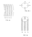
- the plurality of lumens 10a are situated in a ring about the outer circumference of the body member 2 as shown in FIG. 4b .
- the substance(s) may be injected into the lumens 10a for delivery through a delivery mechanism, which may be any of the delivery mechanisms described above or a combination of the delivery mechanisms described above.
- a plurality of lumen 10a are clustered within the body member 2 as shown in FIG. 4c .
- the substance(s) may be injected into the lumens 10a for delivery through a delivery mechanism.
- the inner lumens 10a preferably deliver their housed substances through one or more apertures 16, 16a located near the distal end 6 of the body member 2, while the outer lumens 10a located at the outer circumference of the body member 2 may deliver their housed substances through one or more apertures 16, 16a located near the distal end 6 of the body member 2, a plurality of openings 18 along the body member 2, and/or through the material forming the body member 2 as described above.
- the non-linear body member 2 is formed of a plurality of tubes 20 clustered and wound into a coil shape as shown in FIG. 4d .
- the substance(s) to be delivered is/are inserted into and housed within the plurality of hollow tubes 20.
- the plurality of tubes 20 may contain different substances or the same substance as desired.
- the substances are then delivered by one or more of the delivery mechanisms set out above.
- one or more of the tubes 20 may have one or more exit apertures 22 at their distal ends through which the substance(s) can be delivered.
- One or more tubes 20 may also have a plurality of openings 24 along their lengths through which the substance(s) can be delivered.
- one or more tubes 20 can be fabricated of a material permeable or semi-permeable to the substance contained within the tubes 20.
- each tube 20 can have one or more of the various types of delivery mechanisms and, also, it is possible to for different tubes to have different types of delivery mechanisms.
- each tube 20 can be designed to provide the optimal type of delivery based on the substance to be delivered, the location of delivery and the desired rate of delivery.
- a plurality of substances may be delivered by a single device by providing a body member 2 with a lumen 10 having impermeable dividers 25 located along the length of the lumen 10 as shown for example, in FIG. 5a .
- the lumen 10 would contain a plurality of compartments 26, each of which could be filled with a different substance. These compartments 26 could be filled prior to insertion through an injection port 32 located, for example, in the side of each compartment 16 as shown in FIG. 5b .
- the device may be filled after it is implanted by providing a plurality of conduits 30 each in fluid communication with a corresponding compartment 25.
- conduits 30 may be located within the wall of the body member 2, along the circumference of the body member 2, for example, as shown in FIG. 5c .
- the substances could then be injected through a plurality of ports 34a, 34b, 34c, 34d, 34e each in fluid communication with a corresponding conduit 30.
- a substance could be injected into the first compartment 26a just below the rim or cap 8 by a port 34a in the center of the rim or cap 8, which delivers the substance directly into the first compartment 26a.
- a substance injected into the second port 36b would flow through conduit 30 and would flow through an aperture in the wall of the body member 2 into second compartment 26b, and so on.
- a delivery mechanism which may be one or more of the delivery mechanisms described above.
- substance in compartment 26a may be delivered through one or more apertures 36 in the walls of the compartment 26a.
- Compartment 26b could be fabricated of a material that is permeable or semi-permeable to the substance in the compartment 26b such that substance in compartment 26b may be delivered by diffusion through the walls of the compartment. Such materials are set out above and may be readily determined by those in skill in the art depending on the substance in the compartment to be delivered and the desired rate of delivery of the substance.
- Substance in compartment 26e, located at the end of the non-linear body member 2 could be delivered by an exit port (not shown) located at the distal end of the compartment 26e and, also, could be delivered by a plurality of apertures (not shown) in the walls of the compartment 26e. In this way, each compartment may be designed for optimal delivery the particular substance housed within the compartment.
- each compartment 26a, 26b, 26c, 26d, 26e is designed for selective "opening" or activation by a laser (via heat or photodisruption).
- a laser could be used to create apertures in the walls of the desired compartment 26a. 26b, 26c, 26d or 26e when the particular substance is to be delivered. As such, release of each substance could be controlled upon demand by a physician.
- a pump-driven (e.g. Spring, gas-driven, nitinol, piezoelectric, osmotic) system (not shown) including is coupled to the device, allowing for more sustained delivery.
- the one or more lumens 10, 10a can be refilled by injection into the lumen(s) 10, 10a themselves or through an external conduit.
- a separate pump device and reservoir housing one or more substances could be located within the eye or remotely (i.e. behind the ear subcutaneously). If the pump and reservoir are located behind the ear, a conduit between the pump and the delivery device within the eye could run subcutaneously into the orbit, subconjunctively and through the sclera into the posterior chamber. The conduit must have sufficient slack to allow for ocular movements without displacing the conduit.
- the delivery device may further include a nonbiodegradable backbone (not shown) located along the non-linear body member 2.
- a nonbiodegradable backbone located along the non-linear body member 2.
- one or more thin, wire-like members fabricated of a nonbiodegradable material may be located within the walls of the body member 2 or, for example, in the center of the cluster of tubes 20 shown in FIG. 4d .
- nonbiodegradable materials are well-known and may be readily determined by one of skill in the art.
- some suitable nonbiodegradable polymers may include, for example, polymethylmethacrylate, a silicone elastomer, or silicone rubber.
- suitable non-erodible, biocompatible polymers which may be used in fabricating the body member 2 may include polyolefins such as polypropylene and polyethylene, homopolymers, and copolymers of vinyl acetate such as ethylene vinyl acetate copolymer, polyvinylchlorides, homopolymers and copolymers of acrylates such as polyethylmethacrylate, polyurethanes, polyvinylpyrrolidone, 2-pyrrolidone, polyacrylonitrile butadiene, polycarbonates, polyamides, fluoropolymers such as polytetrafluoroethylene and polyvinyl fluoride, polystyrenes, homopolymers and copolymers of styrene acrylonitrile, cellulose acetate, homopolymers and copolymers of acrylonitrile butadiene styrene, polymethylpentene, polysulfones, polyesters, polyimides, natural rubber, polyiso
- the delivery device 1 includes backbone (not shown) fabricated of a shape memory material described above.
- the body member 2 may be fabricated of any of the materials described above.
- the body member 2 is fabricated of a flexible material and a shape memory backbone located within the wall of the body member 2 or, for example, in the center of a cluster of tubes 20 shown in FIG. 4d .
- the backbone, along with the body portion of the device is first deformed to a shape that makes it easier to insert into the eye, such as a linear shape.
- the backbone will hold the device in this deformed shape.
- the backbone, along with the body portion of the device will then return to the remembered shape.
- the dimensions of the delivery device will depend on the intended application of the device, and will be readily apparent to those having ordinary skill in the art.
- the device when the delivery device is used to deliver substances to the posterior chamber of the eye, the device is preferably designed for insertion through a small incision that requires few of no sutures for scleral closure at the conclusion of the procedure.
- the device is preferably inserted through an incision that is no more than about 1 mm in cross-section, e.g. ranging from about 0.25 mm to about 1 mm in diameter, more preferably less than 0.5 mm in diameter.
- the body member 2 When used to deliver agents to the posterior chamber of the eye, the body member 2 preferably has a length from its proximal end 4 to its distal end 6 that is less than about 1.5 cm, e.g. ranges from about 0.5 cm to about 1.5 cm such that when the rib or cap 8 abuts the outer surface of the eye, the delivery mechanism is positioned near the posterior chamber of the eye.
- the use of the delivery device of the present invention can be further understood from the following discussion relating to a method for treating chronic diseases of the eye by sustained release of therapeutic agent to the eye and with reference to FIGS. 1-6 .
- the delivery device is generally used by the following procedure: the delivery device is prepared, either empty or housing the substance to be delivered.
- an incision is made to provide access to the treatment site.
- a sclerotomy is created for insertion of the delivery device.
- Conventional techniques may be used for the creation of the sclerotomy. Such techniques require the dissection of the conjunctiva 44 and the creation of pars plana scleral incisions through the sclera 46. As shown in FIG.
- the dissection of the conjunctiva 44 typically involves pulling back the conjunctiva 44 about the eye 42 so as to expose large areas of the sclera 46 and the clipping or securing of the conjunctiva 44 in that pulled back state (normal position of conjunctiva shown in phantom).
- the sclera 46 is not exposed only in the areas where the pars plana scleral incisions are to be made. Surgical instruments used in the procedure are then passed through these incisions.
- the incisions created for the procedure must be made large enough to accommodate the instruments required for the procedure.
- the distal end 6 may be pointed or beveled and used to create the incision.
- the creation of the sclerotomy may be accomplished by use of an alignment device and method, such as that described in U.S.S.N. 09/523,767 , the teachings of which are incorporated herein by reference, that enables sutureless surgical methods and devices therefore.
- an alignment device and method such as that described in U.S.S.N. 09/523,767 , the teachings of which are incorporated herein by reference, that enables sutureless surgical methods and devices therefore.
- such methods and devices do not require the use of sutures to seal the openings through which instruments are inserted.
- the alignment devices are inserted through the conjunctiva and sclera to form one or more entry apertures.
- the alignment devices are metal or polyimide cannulas through which the surgical instruments used in the procedure are inserted into the eye.
- the body member 2 is then inserted into the eye.
- the body member 2 is inserted into the eye by screwing or twisting the body member 2 into eye until the rim or cap 8 abuts the outer surface of the eye.
- the shape memory material is first cooled to a temperature at which the martensite phase is stable and the device is deformed, for example, into a linear shape. The device is then inserted into the eye. To return the device to its memory shape, the device is left unrestrained and is simply heated to a temperature above the martensite phase temperature.
- the shape memory material may be heated by a laser to return the device to a temperature above the martensite phase temperature.
- the shape memory material may also be selected such that the martensite phase temperature is below body temperature so that the material is simply cooled to below body temperature, deformed to a linear shape and inserted into the eye. Then, as the material warms up within the eye to body temperature, the device returns to its remembered shape.
- the rim or cap 8 may then be sutured or otherwise secured to the sclera to hold the delivery device in place. If a cover is used to close the port(s) 12, 12a it is removed at this time, and, if used, a collar for providing a snug fit about the syringe or other injection mechanism is mounted on the port(s) 12, 12a. The syringe or other injection mechanism is then connected to the port(s) 12, 12a for injection of the one ore more substances into the delivery device.
- the port(s) 12, 12a are composed of an injectable self-sealing material through which the needle of a syringe or other injection mechanism may be inserted and which seals off automatically when the needle other injection mechanism is removed, the needle or other injection mechanism is simply inserted through the port and the substance injected. Following injection, the conjunctiva may be adjusted to cover the rim or cap 8 of the device.
- some substances suitable for delivery to the eye may include, for example, antibiotics such as tetracycline, chlortetracycline, bacitracin, neomycin, polymyxin, gramicidin, cephalexin, oxytetracycline, chloramphenicol, rifampicin, ciprofloxacin, tobramycin, gentamycin, and erythromycin and penicillin; antifungals such as amphotericin B and miconazole; antibacterials such as sulfonamides, sulfadiazine, sulfacetamide, sulfam
- additives may further be included in the substance and, for example, some suitable additives may include water, saline, dextrose, carriers, preservatives, stabilizing agents, wetting agents, emulsifying agents or other similar materials.
- the delivery device may be refilled for further delivery or removed if the required dose of agent has been delivered for treatment of the condition.
- the invention is not be limited to ocular applications, and is particularly useful in other limited access regions such as the inner ear.
- kits that comprise one or more devices of the invention, preferably packaged in sterile condition.
- Kits of the invention also may include, for example, one or more body members 2, means for suturing or securing the device to the sclera, etc. for use with the device, preferably packaged in sterile condition, and/or written instructions for use of the device and other components of the kit.
Abstract
Description
- The present application claims the benefit of
U.S. provisional application 60/228,934, filed August 30,2000 - The present invention relates to a device and method for intraocular delivery of therapeutic agents. Preferred devices of the invention include a non-linear portion that resides within a patient's eye during use that can facilitate the delivery of a therapeutic agent.
- The delivery of drugs to the eye presents many challenges. The ocular absorption of systemically administered pharmacologic agents is limited by the blood ocular barrier, namely the tight junctions of the retinal pigment epithelium and vascular endothelial cells. High systemic doses can penetrate this blood ocular barrier in relatively small amounts, but expose the patient to the risk of systemic toxicity. Topical delivery of drugs often results in limited ocular absorption due to the complex hydrophobic/hydrophilic properties of the cornea and sclera. Additionally, topical agents are mechanically removed by the blink mechanism such that only approximately 15% of a single drop is absorbed. Diffusion of topically administered drugs to the posterior chamber occurs, but often at sub-therapeutic levels. Intravitreal injection of drugs is an effective means of delivering a drug to the posterior segment in high concentrations. However, these repeated intraocular injections carry the risk of infection, hemorrhage and retinal detachment. Patients also find this procedure somewhat difficult to endure.
- Local sustained delivery of therapeutics to the posterior chamber is critical in managing several chronic diseases of the eye. To address this need, several drug delivery devices have been developed for intraocular insertion into the vitreous region of the eye.
-
U.S. Patent No. 4,300,557 , for example, describes an intraocular implant in the form of a silicone capsule, which can be filled with a drug to be delivered. The implant is inserted through an incision into the vitreous region of the eye. After insertion of the implant, the incision is closed and the capsule remains in place for a period of time. Attached to the implant is a tube that passes through the surface of the eye. The tube may be used for subsequent injection of a drug while the implant is in the eye. The implant may be removed by making a second surgical incision into the eye and retrieving the implant. While in the vitreous, the device is not anchored and may move about freely. Because the overall shape of the capsule is linear, the amount of drug that may held by the device and that may be delivered over the surface area of the device is limited. If the width of the capsule is increased, excessive sized incisions will be required for insertion of the device. If the length of the capsule is increased to greater than 1 cm, the implant will pass into the central visual field of the eye, thereby causing blind spots in the patient's eye as well as increase risk of damage to the retinal tissue and lens capsule. -
U.S. Patent No. 5,378,475 describes a device which has been developed for insertion in the vitreous region of the eye, and is described in T.J. Smith et al., Sustained-Release Ganciclovir, Arch. Ophthalmol, 110, 255-258 (1992) and G.E. Sanborn, et al., Sustained-Release Ganciclovir Therapy for Treatment of Cytomegalovirus Retinitis. Use of an Intravitreal Device, Arch. Ophthalmol, 110, 188-195 (1992). This device consists of an inner core of pharmacologic agent surrounded by two coatings with different permeabilities. Drug diffuses through a small opening in one of these coatings achieving near-order release kinetics. It is implanted in the region of the pars plana through a 3.5-5.0 mm scleral incision. The implant must be removed and replaced every 6 months in the operating room as the drug becomes depleted. There is an approximately 25% complication rate from these procedures. The device is membrane diffusion drug delivery system that relies on EVA/PVA polymers to mediate release rate. Thus, many agents cannot be effectively delivered from such a system because their permeation rate through the rate controlling material of the system is too small to produce a useful effect. Other agents cannot be satisfactorily delivered by diffusional devices because of a particular chemical characteristic of the agent. This includes salts, because of their ionic character, and unstable polar compounds that cannot be formulated into a composition suitable for storage and delivery from such systems. -
U.S. Patent No. 5,098,443 describes certain specific implants that are inserted through incisions made in the eye wall or sutured around the globe of the eye. These rings may be formed from biodegradable polymers containing microparticles of drug. Alternatively, the implant may be in the form of a hollow flexible polymeric cocoon with the drug disposed therewithin for slow release by osmosis. No anchoring device is described. -
U.S. Patent No. 5,466,233 describes a certain tack for intraocular drug delivery. This device has an end that is positioned in the vitreous cavity while the head remains external to the eye and abuts the scleral surface. The tack contains a fixation portion to attempt to retain attachment within the eye. Because the overall shape of the capsule is linear, the amount of drug that may held by the device and the surface area through which the drug may be delivered is limited. If the width of the capsule is increased, excessive sized incisions will be required for insertion of the device. If the length of the capsule is increased to greater than 1 cm, the implant will pass into the central visual field of the eye, thereby causing blind spots in the patient's eyes well as increase risk of damage to the retinal tissue and lens capsule. - The present invention provides methods and devices for the intraocular delivery of substances including, for example, therapeutic agents and medicaments.
- Preferred devices of the invention have a non-linear shape during residence within a patient's eye. Preferred designs have multiple turns or angles, particularly substantially coil or helical configurations, at least for those portions that reside within a patient's eye during use.
- Preferred device of the invention also include those that have a quite small cross-section shape, at least with respect to areas that reside within a patient's eye during use. Such devices can be implanted by minimally invasive surgical procedures, including without the need for any sutures to implant or after use of the use.
- An exemplary embodiment of the delivery device includes a body member that is non-linear in shape. In one embodiment, the device has a non-linear shape before, during and after the device is inserted into the eye. In another embodiment, the device is fabricated of a "shape memory" material wherein the device is linear as it is inserted into the eye and wherein the device takes on a non-linear shape once it is implanted in the eye. Preferred shape memory materials include known materials such as, for example, shape memory alloys (SMA) like nitinol, shape memory polymers (SMP) like AB-polymer networks based on oligo(e-caprolactone) dimethacrylates and n-butyl acrylate.
- We have found the non-linear shape of the body member provides a number of advantages. The non-linear shape provides a built-in anchoring mechanism that prevents unwanted movement of the device and unwanted ejection of the device out of the eye since the non-linear shape of the body member requires manipulation of the device to get it out of an incision. For example, in a preferred embodiment, wherein the implant is in the shape of a coil, the device can be removed only by twisting the device out of the eye and, thus, is not susceptible to ejection by the eye or unwanted movement within the eye. Further, the non-linear shape geometry of the body member provides greater surface area per length of the device. This is advantageous because it is desirable to limit the length of drug delivery implants to prevent the implant from entering the central visual field (See
FIG. 6 which follows). If the implant enters the central visual field, this will result in blind spots in the patient's vision and wi1l increase the risk of damage to the retina tissue and lens capsule. By forming the body member in a non-linear shape, the device of the present invention holds a greater volume of materials per length of the device and it also provides a larger surface area per length of the device through which the material may be delivered. - The delivery device may further include a rim or cap at its proximal end. During use, the device is inserted into the eye through an incision until the rim or cap abuts the incision. If desired, the rim or cap may then be sutured to the eye to further stabilize and prevent the device from moving once it is implanted in its desired location.
- In one embodiment, body member has a lumen extending along its length for housing the substance to be delivered. Preferably, a port in fluid communication with the lumen is located at the proximal end of the device. This allows for filling and refilling of the device after the device has been implanted in the eye. The substance in the lumen can then be delivered to the eye by a delivery mechanism. The lumen, in some embodiments, may further include a number of dividers to form a plurality of compartments each of which could be filled with a different substance, thereby allowing for delivery of more that one substances by the same device at the same time, if desired.
- In one embodiment, the delivery mechanism comprises one or more exit apertures located at the distal end of the body member. In another embodiment, the delivery mechanism comprises a plurality of openings along the body member. In another embodiment, the delivery mechanism comprises the material forming the body member. For example, the material forming the body member may be a material that is permeable or semi-permeable to the substance to be delivered. In another embodiment, the body member is fabricated of a synthetic biodegradable polymer containing microparticles of the substance to be delivered. As the polymer decomposes, the substance to be delivered is released into the eye.
- Other aspects and embodiments of the invention are discussed infra.
-
-
FIG. 1 illustrates transcleral placement of the delivery device in accordance with one embodiment of the present invention. -
FIG. 2a illustrates the delivery device in accordance with one embodiment of the present invention. -
FIG. 2b is an enlarged view of a portion of the body member of the delivery device shown inFIG. 2a showing the lumen. -
FIG. 2c is an enlarged cross-sectional view of the body member of the delivery device shown inFIG. 2a . -
FIG. 3a illustrates the delivery device having a delivery mechanism in accordance with one embodiment of the present invention. -
FIG. 3b illustrates the delivery device having a delivery mechanism in accordance with another embodiment of the present invention. -
FIG. 3c illustrates the delivery device having a delivery mechanism in accordance with another embodiment of the present invention. -
FIG. 4a is an enlarged view of a portion of the body member of the delivery device in accordance with another embodiment of the present invention showing a plurality of lumen. -
FIG. 4b is an exploded view of the cap or rim and a portion of the body member shown inFIG. 4a showing one arrangement of a plurality of lumen. -
FIG. 4c is an exploded view of the cap or rim and a portion of the body member shown inFIG. 4a showing another arrangement of a plurality of lumen. -
FIG. 4d illustrates another embodiment of the body member comprising a cluster of tubes. -
FIG. 5a illustrates the delivery device in accordance with another embodiment of the present invention showing a lumen separated into a plurality of compartments. -
FIG. 5b shows the delivery device ofFIG. 5a and further shows one type of delivery mechanism in accordance with the present invention. -
FIG. 6 shows a shows a cross-sectional view of an eye illustrating the central visual field of the eye. -
FIG. 7 shows a cross-sectional schematic view of an eye illustrating one technique of pulling back of the conjunctiva to provide access into the eye for insertion of the delivery device of the present invention. - As discussed above, preferred delivery devices of the invention have a non-linear (arcuate) shape during residence within a patient's eye. Preferred designs have multiple turns or angles. For example, preferred designs the device has at least two, three, four, five, six, seven, right, nine or ten separate deviations from a linear path. A coil design is particularly preferred, although other multiple-angle configurations are also suitable such as a substantially Z- shape and the like.
- Referring now to the various figures of the drawing, wherein like reference characters refer to like parts, there is shown various views of a
delivery device 1, in accordance with the invention. - As shown in
FIGS. 1-5c , thedelivery device 1 includes a non-linearshaped body member 2 having aproximal end 4, adistal end 6. In one preferred embodiment, thebody member 2 has a coil shape, as shown inFIGS. 1-5c . However, the shape of thebody member 2 is not limited to a coil shape and other non-linear shapes may be used such as, for example, other random curled shapes, a zig-zag shape, a "J" shape and the like. For at least some aspects of the invention, a substantially "C'' shape configuration is less preferred. - As discussed above, the non-linear shape of the
body member 2 provides a number of advantages. The large intravitreal surface area provided by the non-linear shape geometry of thebody member 2 can allow for more optimal sustained release of the substance through diffusion, enzymatic degradation, active pumping and other types of delivery. When implanted in the eye, it is desirable to limit the length "L'' of drug delivery implants prevent the drug delivery implant from entering the central visual field "A'' (See F1G. 6). If the implant enters the central visual field A, this will result in blind spots in the patient's vision and will increase the risk of damage to the retina tissue and lens capsule. Thus, for example, when the implant is inserted at the pars plana, the distance from the implantation site on the pars plana to the central visual field is approximately 1 cm. Thus, the overall length of the implant is preferably less than 1 cm. By providing abody member 2 that has a non-linear shape, the device of the present invention holds a greater volume of materials per length of the device without having to make the cross section of the device and, thus, the size of the insertion incision) larger, and it also provides a larger surface area per length of the device through which the material may be delivered. Still further, the non-linear shape of thebody member 2 provides a built-in anchoring system that prevents unwanted movement of the device and unwanted ejection of the device out of the eye since the non-linear shape of the body member requires manipulation of the device to get it out of an incision (e.g. a coil-shapedbody member 2 would require twisting the device out of the eye, and a zig-zag shapedbody member 2 would require moving the device back and forth to remove the device from the eye). - In one preferred embodiment, the delivery device has a coil-shaped
body member 2 as shown inFIGS. 1-5c . The coil shape of the device provides a large intravitreal surface area through which material can be delivered. Further, the coil shape of the body member allows the device to be screwed or twisted into the eye through an incision approximately the same size as the outer diameter of the tube forming thebody member 2. Still further, the coil shape of the body member acts as an anchoring mechanism that holds thedelivery device 1 within the eye and prevents unwanted movement of the delivery device and unwanted ejection of thedelivery device 1 out of the eye. Due to the coil shape, thedelivery device 1 must be twisted and unscrewed out of the eye. - In general, the materials used in fabricating the
body member 2 are not particularly limited, provided these materials are biocompatible. Preferably, these materials are also insoluble in the body fluids and tissues that the device comes into contact with. It is further preferred that thebody member 2 is fabricated of a flexible material so that small movements of the delivery device will not be translated to the retina, thereby minimizing the risk of retinal tearing, detachment and other damage. In some embodiments, as described in further detail below, it is preferable that at least thedistal end 6 ofbody member 2 is fabricated of a rigid, non-pliable material. In some embodiments, as described in further detail below, it is preferable that at least a portion of the material used to form thebody member 2 is permeable or semi-permeable to the substance to be delivered. In some embodiments, as set out above, it is preferable that the body member is fabricated of a material having shape memory and/or superelastic characteristics. - In one embodiment, the
body member 2 is fabricated of a nonbiodegradable polymer. Such nonbiodegradable polymers are well-known and may include, for example, polymethylmethacrylate, a silicone elastomer, or silicone rubber. Other suitable non-erodible, biocompatible polymers which may be used in fabricating thebody member 2 may include polyolefins such as polypropylene and polyethylene, homopolymers, and copolymers of vinyl acetate such as ethylene vinyl acetate copolymer, polyvinylchlorides, homopolymers and copolymers of acrylates such as polyethylmethacrylate, polyurethanes, polyvinylpyrrolidone, 2-pyrrolidone, polyacrylonitrile butadiene, polycarbonates, polyamides, fluoropolymers such as polytetrafluoroethylene and polyvinyl fluoride, polystyrenes, homopolymers and copolymers of styrene acrylonitrile, cellulose acetate, homopolymers and copolymers of acrylonitrile butadiene styrene, polymethylpentene, polysulfones, polyesters, polyimides, natural rubber, polyisobutylene, polymethylstyrene and other similar non-erodible biocompatible polymers. - The
body member 2 of thedelivery device 1 can, in one embodiment, have a non-linear shape prior to, during and after insertion of the device into the eye. Alternatively, thedelivery device 1 can be fabricated of a material having shape memory and/or superelastic characteristics that allows the device to be deformed and made, for example, linear, for easier insertion into the eye and which returns to its original shape after it is inserted into the eye. In this embodiment, thedelivery device 1 has a "memory shape" that it will take on under certain conditions. For example, thedelivery device 1 may have a zig-zag or coiled memory shape. Then, when the surgeon wishes to implant the device into the eye, the surgeon may deform thedelivery device 1 into a linear shape for quick and easy insertion of the device through an incision the size of the cross section of the linear shaped device. Upon insertion of thedelivery device 1, the device can then take on its zig-zag, coiled or other memory shape. - Materials having shape memory and/or superelastic characteristics are well-known and may include any materials known in the art such as, for example, shape memory alloys (SMA) like nitinol (Ni-Ti alloy) and shape memory polymers (SMP) like AB-polymer networks based on oligo(e-caprolactone) dimethacrylates and n-butyl acrylate. Shape memory alloys generally have at least two phases: (1) a martensite phase, which has a relatively low tensile strength and which is stable at relatively low temperatures, and (2) an austenite phase, which has a relatively high tensile strength and which is stable at temperatures higher than the martensite phase. The shape memory characteristics are imparted on the material by heating the material to a temperature above the temperature at which the austenite phase is stable. While the material is heated to this temperature, the device is held in the "memory shape'', which is shape that is desired to be "remembered". Such materials and methods of imparting shape memory characteristics are further described in, for example,
U.S. Patent No. 4,665,905 ,U.S. Patent No. 4,925,445 andU.S. Patent No. 6,245,100 . - Preferably, the delivery device of the present invention takes advantage of the superelastic properties of the material to extend the device into a linear shape. Once injected into the eye in an unconstrained form, the device will retain its memory shape.
- The
distal end 6 of thebody member 2 may be blunt or, in some embodiments, it is pointed or has a beveled ramp-like configuration so that thedistal end 6 may be used to pierce the eye during insertion. In one embodiment, thedistal end 6 has a ramp-like angle of about 30°. If thedistal end 6 of thebody member 2 is used to pierce the eye during insertion, at least thedistal end 6 is fabricated of a rigid, non-pliable material suitable for piercing the eye. Such materials are well known and may include, for example, polyimide and similar materials. - As shown in
FIGS. 1 ,2a ,3a-c and5a-c , a rim orcap 8 may further be located at theproximal end 4 of thebody member 2 to assist in stabilizing thedevice 1 once implanted in the eye. Preferably, thedelivery device 1 is inserted into the eye through an incision until the rim orcap 8 abuts the incision. If desired, the rim orcap 8 may then be sutured to the eye to further stabilize and prevent the device from moving once it is implanted in its desired location. - The overall size and shape of the rim or
cap 8 is not particularly limited provided that irritation to the eye is limited. For example, while the rim orcap 8 is shown circular in shape, the rim or cap may be of any shape, for example, circular, rectangular, triangular, etc. However, to minimize irritation to the eye, the rim orcap 8 preferably has rounded edges. Further, the rim orcap 8 is designed such that it remains outside the eye and, as such, the rim orcap 8 is sized so that it will not pass into the eye through the opening in the eye through which the device is inserted. The rim orcap 8 may further be designed such that it can be easily sutured or otherwise secured to the surface surrounding the opening in the eye and may, for example, contain a plurality of holes (not shown) through which sutures may pass. - The materials used in fabricating the rim or
cap 8 are not particularly limited, provided these materials are biocompatible and preferably insoluble in the body fluids and tissues that the device comes into contact with. Further, it is preferred that the rim orcap 8 is fabricated of a material that does not cause irritation to the portion of the eye that it contacts. As such, preferred materials are pliable and may include, by way of example, various polymers including, for example, silicone elastomers and rubbers, polyolefins, polyurethanes, acrylates, polycarbonates, polyamides, polyimides, polyesters, and polysulfones. - In one embodiment, as show in
FIGS. 2a-4c and5a-5c . thenon-linear body member 2 is fabricated of a tube that is wound into a coiled shape. As shown in the Figures, the tube forming thenon-linear body member 2 is preferably cylindrical in shape, with a circular cross-section. However, the shape of the tube is not limited and, for example, may alternatively have square, rectangular, octagonal or other cross-sectional shapes. Preferably, the tube has alumen 10 extending along its length for housing the substance to be delivered. In one embodiment, thelumen 10 is filled with the substance prior to inserting the device into the eye. Alternatively, thelumen 10 may be filled with the substance after the delivery device has been inserted into the eye. This may be accomplished by providing aport 12 near theproximal end 4 of thebody member 2 in fluid communication with thelumen 10. This further allows for refilling of the device during use, if required. - In one embodiment, the
port 12 is preferably designed such that the needle of a syringe, or similar injection mechanism, may be inserted into theport 12 and the substance injected by the syringe or injection mechanism. Thus, the substance travels through theport 12 and into thelumen 10. Theport 12 preferably forms a snug seal about the needle of the syringe or injection mechanism to prevent leakage of the substance out of theport 12 around the syringe needle or injection mechanism and to provide sterile injection of agent into thelumen 10. If desired, fittings or collars (not shown), through which a syringe needle or injection mechanism may be inserted and which form a snug seal about the syringe needle or injection mechanism, may be mounted on theport 12. Upon injection of the substance into the delivery device, the needle of the syringe or the injection mechanism is removed from theport 12 and theport 12 sealed. This may be accomplished by providing a removable cover (not shown) on theport 12 that may be removed for injection of the substance and replaced when the substance has been injected. In a preferred embodiment, theport 12 is fabricated of an injectable self-sealing material through which the needle or injection mechanism may be inserted and which seals off automatically when the needle or injection mechanism is removed. Such materials are known and include, for example, silicone rubber, silicone elastomers and polyolefin. - Once the device is implanted in the desired location and the substance is housed within the
lumen 10, the substance can then be delivered to the eye by a delivery mechanism. - In one embodiment, as shown in
FIG. 3a , the delivery mechanism comprises anexit aperture 16 located at thedistal end 6 of thebody member 2. Alternatively, as shown inFIG. 3b , a plurality ofexit apertures 16a located at thedistal end 6 of thebody member 2 may form the delivery mechanism. The number and size of the one ormore exit apertures 16 may vary depending on the desired rate of delivery of the agent and may be readily determined by one of skill in the art. The one ormore exit apertures 16 are designed such that the substance is slowly diffused rather than expelled as a fluid stream, which may damage the delicate tissues of the eye. For example, in one embodiment, this may be achieved by, for example, placing a covering or lining (not shown) over thedistal exit aperture 16, wherein the covering or lining has a particular porosity to the agent or wherein the covering or lining is fabricated of a diffusion or rate-limiting membrane, matrix material or similar material. - In another embodiment, for example, as shown in
FIG. 3c , the delivery mechanism comprises a plurality ofopenings 18 along thebody member 2. The number and size of the one ormore openings 18 may vary depending on the desired rate of delivery of the agent and may be readily determined by one of skill in the art. Further, the location of the plurality ofopenings 18 may be situated so as to deliver the substance at a particular location once the device is implanted in the eye. The plurality ofopenings 18 are designed such that the substance is slowly diffused rather than expelled as a fluid stream, which may damage the delicate tissues of the eye. In this embodiment, anexit aperture 16 at thedistal end 6 of thebody member 2 as described above may also be included. - In another embodiment, the delivery mechanism comprises the material forming the
body member 2. For example, the material forming thebody member 2 may be a material that is permeable or semi-permeable to the substance to be delivered. Such materials may vary depending on the particular application and the substance to be delivered and may be readily determined by one of skill in the art. By way of example, some suitable permeable materials may include polycarbonates, polyolefins, polyurethanes, copolymers of acrylonitrile, copolymers of polyvinyl chloride, polyamides, polysulphones, polystyrenes, polyvinyl fluorides, polyvinyl alcohols, polyvinyl esters, polyvinyl butyrate, polyvinyl acetate, polyvinylidene chlorides, polyvinylidene fluorides, polyimides, polyisoprene, polyisobutylene, polybutadiene, polyethylene, polyethers, polytetrafluoroethylene, polychloroethers, polymethylmethacrylate, polybutylmethacrylate, polyvinyl acetate, nylons, cellulose, gelatin, silicone rubbers and porous rubbers. - The particular material used to fabricate the
body member 2 may be chosen to provide a particular rate of delivery of the substance, which may be readily determined by one of skill in the art. Further, the rate of delivery of the substance may also be increased or decreased by varying the percentage of thebody member 2 formed of the material permeable to the agent. Thus, for example, to provide a slower rate of delivery, thebody member 2 may be fabricated of 50% or less permeable material. For example, thebody member 2 may be fabricated of 1%, 5%, 10%, 20%, 30%, 40% or 50% of permeable material. For a faster rate of delivery, thebody member 2 may be fabricated of greater than 50% of permeable material. For example, thebody member 2 may be fabricated of 51%, 55%, 60%, 70%, 80%, 90% or 100% of permeable material. When one or more portions of thebody member 2, rather than thewhole body member 2, is fabricated of a permeable or semi-permeable material, the location of the permeable or semi-permeable material may be situated so as to deliver the substance at a particular location once the device is implanted in the eye. - In another embodiment, the
body member 2 is fabricated of a synthetic biodegradable polymer containing microparticles of the substance to be delivered. Thus, in this embodiment, as the polymer decomposes, the substance to be delivered is released into the eye. Release time is a function of the polymer and the shape and size of thebody member 2 and may be readily determined by one of ordinary skill in the art. Such biodegradable polymers may vary depending on the particular application and may be readily determined by one of skill in the art. By way of example, some suitable biodegradable polymers may include polyesters of molecular weight from about 4,000 to about 100,000, homopolymers and copolymers of polylactic acid and polyglycolic acid, polycaprolactone, homopolymers and copolymers of polyanhydrides such as terephthalic acid anhydride, bis(p-anhydride) and poly(p-carboxyphenoxy) alkyl, homopolymers and copolymers of dicarboxylic acids such as sebacic, adipic, oxalic, phthalic and maleic acid, polymeric fatty acid dimer compounds such as polydodecanedioic acid polyorthoesters, poly(alkyl-2-cyanoacrylate) such as poly(hexyl-2-cyanoacrylate), collagen (gelatin), polyacetals, divinyloxyalkylenes, polydihydropyrans, polyphosphazenes, homopolymers and copolymers of amino acids such as copolymers of leucine and methyl glutamate, polydioxinones, polyalkylcyano acetates, polysaccarides and their derivatives such as dextran and cyclodextran, cellulose and hydroxymethyl cellulose. - In another embodiment, rather than a
single lumen 10, thenon-linear body member 2 includes a plurality oflumens 10a capable of housing and delivering a plurality of substances. Thus, for example, eachlumen 10a may be in fluid communication with plurality ofports 12a. Theseports 12a are similar to thesingle port 12 described above. (e.g. theports 12a may include a cover that may be removed for injection of the substance and replaced when the substance has been injected, or theports 12a may be fabricated of an injectable self-sealing material) If desired, thelumens 10a andports 12a may be arranged such that eachlumen 10a may be filled with a different substance through the correspondingports 12a. Thus, the single device may be used to deliver more than one substance if desired. - In one embodiment, the plurality of
lumens 10a are situated in a ring about the outer circumference of thebody member 2 as shown inFIG. 4b . The substance(s) may be injected into thelumens 10a for delivery through a delivery mechanism, which may be any of the delivery mechanisms described above or a combination of the delivery mechanisms described above. - In another embodiment, a plurality of
lumen 10a are clustered within thebody member 2 as shown inFIG. 4c . The substance(s) may be injected into thelumens 10a for delivery through a delivery mechanism. In this embodiment, theinner lumens 10a preferably deliver their housed substances through one ormore apertures distal end 6 of thebody member 2, while theouter lumens 10a located at the outer circumference of thebody member 2 may deliver their housed substances through one ormore apertures distal end 6 of thebody member 2, a plurality ofopenings 18 along thebody member 2, and/or through the material forming thebody member 2 as described above. - In yet another embodiment, the
non-linear body member 2 is formed of a plurality oftubes 20 clustered and wound into a coil shape as shown inFIG. 4d . In this embodiment, the substance(s) to be delivered is/are inserted into and housed within the plurality ofhollow tubes 20. The plurality oftubes 20 may contain different substances or the same substance as desired. The substances are then delivered by one or more of the delivery mechanisms set out above. For example, in one embodiment, one or more of thetubes 20 may have one ormore exit apertures 22 at their distal ends through which the substance(s) can be delivered. One ormore tubes 20 may also have a plurality of openings 24 along their lengths through which the substance(s) can be delivered. Still further, one ormore tubes 20 can be fabricated of a material permeable or semi-permeable to the substance contained within thetubes 20. Thus, it is possible for eachtube 20 to have one or more of the various types of delivery mechanisms and, also, it is possible to for different tubes to have different types of delivery mechanisms. In this way, eachtube 20 can be designed to provide the optimal type of delivery based on the substance to be delivered, the location of delivery and the desired rate of delivery. - In another embodiment, a plurality of substances may be delivered by a single device by providing a
body member 2 with alumen 10 havingimpermeable dividers 25 located along the length of thelumen 10 as shown for example, inFIG. 5a . Thus, thelumen 10 would contain a plurality ofcompartments 26, each of which could be filled with a different substance. Thesecompartments 26 could be filled prior to insertion through aninjection port 32 located, for example, in the side of eachcompartment 16 as shown inFIG. 5b . In another embodiment, the device may be filled after it is implanted by providing a plurality ofconduits 30 each in fluid communication with acorresponding compartment 25. Theseconduits 30 may be located within the wall of thebody member 2, along the circumference of thebody member 2, for example, as shown inFIG. 5c . The substances could then be injected through a plurality ofports corresponding conduit 30. Thus, a substance could be injected into thefirst compartment 26a just below the rim orcap 8 by aport 34a in the center of the rim orcap 8, which delivers the substance directly into thefirst compartment 26a. A substance injected into the second port 36b, would flow throughconduit 30 and would flow through an aperture in the wall of thebody member 2 intosecond compartment 26b, and so on. - The substance injected into each of the
compartments compartment 26a may be delivered through one ormore apertures 36 in the walls of thecompartment 26a.Compartment 26b could be fabricated of a material that is permeable or semi-permeable to the substance in thecompartment 26b such that substance incompartment 26b may be delivered by diffusion through the walls of the compartment. Such materials are set out above and may be readily determined by those in skill in the art depending on the substance in the compartment to be delivered and the desired rate of delivery of the substance. Substance in compartment 26e, located at the end of thenon-linear body member 2 could be delivered by an exit port (not shown) located at the distal end of the compartment 26e and, also, could be delivered by a plurality of apertures (not shown) in the walls of the compartment 26e. In this way, each compartment may be designed for optimal delivery the particular substance housed within the compartment. - In another embodiment, each
compartment compartment 26a. 26b, 26c, 26d or 26e when the particular substance is to be delivered. As such, release of each substance could be controlled upon demand by a physician. - In yet another embodiment, a pump-driven (e.g. Spring, gas-driven, nitinol, piezoelectric, osmotic) system (not shown) including is coupled to the device, allowing for more sustained delivery. In this embodiment, the one or
more lumens - For added structural support, the delivery device may further include a nonbiodegradable backbone (not shown) located along the
non-linear body member 2. For example, in one embodiment, one or more thin, wire-like members fabricated of a nonbiodegradable material, may be located within the walls of thebody member 2 or, for example, in the center of the cluster oftubes 20 shown inFIG. 4d . Such nonbiodegradable materials are well-known and may be readily determined by one of skill in the art. By way of example, some suitable nonbiodegradable polymers may include, for example, polymethylmethacrylate, a silicone elastomer, or silicone rubber. Other suitable non-erodible, biocompatible polymers which may be used in fabricating thebody member 2 may include polyolefins such as polypropylene and polyethylene, homopolymers, and copolymers of vinyl acetate such as ethylene vinyl acetate copolymer, polyvinylchlorides, homopolymers and copolymers of acrylates such as polyethylmethacrylate, polyurethanes, polyvinylpyrrolidone, 2-pyrrolidone, polyacrylonitrile butadiene, polycarbonates, polyamides, fluoropolymers such as polytetrafluoroethylene and polyvinyl fluoride, polystyrenes, homopolymers and copolymers of styrene acrylonitrile, cellulose acetate, homopolymers and copolymers of acrylonitrile butadiene styrene, polymethylpentene, polysulfones, polyesters, polyimides, natural rubber, polyisobutylene, polymethylstyrene and other similar non-erodible biocompatible polymers. - In another embodiment, the
delivery device 1 includes backbone (not shown) fabricated of a shape memory material described above. In this embodiment, for example, thebody member 2 may be fabricated of any of the materials described above. In one embodiment, for example, thebody member 2 is fabricated of a flexible material and a shape memory backbone located within the wall of thebody member 2 or, for example, in the center of a cluster oftubes 20 shown inFIG. 4d . Thus, the backbone, along with the body portion of the device, is first deformed to a shape that makes it easier to insert into the eye, such as a linear shape. The backbone will hold the device in this deformed shape. After the device is inserted into the eye, the backbone, along with the body portion of the device, will then return to the remembered shape. - The dimensions of the delivery device will depend on the intended application of the device, and will be readily apparent to those having ordinary skill in the art. By way of example, when the delivery device is used to deliver substances to the posterior chamber of the eye, the device is preferably designed for insertion through a small incision that requires few of no sutures for scleral closure at the conclusion of the procedure. As such, the device is preferably inserted through an incision that is no more than about 1 mm in cross-section, e.g. ranging from about 0.25 mm to about 1 mm in diameter, more preferably less than 0.5 mm in diameter. As such, the cross-section of the tube forming the
body member 2, or the cluster oftubes 20 as shown inFIG. 4d , is preferably no more than about 1 mm, e.g. preferably ranging from about 0.25 mm to about 1 mm in diameter, and, more preferably, is no greater than 0.5 mm. If the tube forming thebody member 2 is not cylindrical, the largest dimension of the cross section can be used to approximate the diameter for this purpose. When used to deliver agents to the posterior chamber of the eye, thebody member 2 preferably has a length from itsproximal end 4 to itsdistal end 6 that is less than about 1.5 cm, e.g. ranges from about 0.5 cm to about 1.5 cm such that when the rib orcap 8 abuts the outer surface of the eye, the delivery mechanism is positioned near the posterior chamber of the eye. - The use of the delivery device of the present invention can be further understood from the following discussion relating to a method for treating chronic diseases of the eye by sustained release of therapeutic agent to the eye and with reference to
FIGS. 1-6 . - The delivery device is generally used by the following procedure: the delivery device is prepared, either empty or housing the substance to be delivered.
- In one embodiment, an incision is made to provide access to the treatment site. For example, when used to deliver therapeutic agent to the posterior chamber of the eye, a sclerotomy is created for insertion of the delivery device. Conventional techniques may be used for the creation of the sclerotomy. Such techniques require the dissection of the
conjunctiva 44 and the creation of pars plana scleral incisions through thesclera 46. As shown inFIG. 6 , the dissection of theconjunctiva 44 typically involves pulling back theconjunctiva 44 about theeye 42 so as to expose large areas of thesclera 46 and the clipping or securing of theconjunctiva 44 in that pulled back state (normal position of conjunctiva shown in phantom). In other words, thesclera 46 is not exposed only in the areas where the pars plana scleral incisions are to be made. Surgical instruments used in the procedure are then passed through these incisions. Thus, the incisions created for the procedure must be made large enough to accommodate the instruments required for the procedure. Alternatively, during this procedure, rather than making an incision through which the device is inserted, thedistal end 6 may be pointed or beveled and used to create the incision. - Alternatively, the creation of the sclerotomy may be accomplished by use of an alignment device and method, such as that described in
U.S.S.N. 09/523,767 - The
body member 2 is then inserted into the eye. For example, in embodiments wherein thebody member 2 has a coiled shape, thebody member 2 is inserted into the eye by screwing or twisting thebody member 2 into eye until the rim orcap 8 abuts the outer surface of the eye. In embodiments wherein thebody member 2 or a backbone of the body member is fabricated of a shape memory material, the shape memory material is first cooled to a temperature at which the martensite phase is stable and the device is deformed, for example, into a linear shape. The device is then inserted into the eye. To return the device to its memory shape, the device is left unrestrained and is simply heated to a temperature above the martensite phase temperature. For example, the shape memory material may be heated by a laser to return the device to a temperature above the martensite phase temperature. The shape memory material may also be selected such that the martensite phase temperature is below body temperature so that the material is simply cooled to below body temperature, deformed to a linear shape and inserted into the eye. Then, as the material warms up within the eye to body temperature, the device returns to its remembered shape. - After the device is inserted into the eye, the rim or
cap 8 may then be sutured or otherwise secured to the sclera to hold the delivery device in place. If a cover is used to close the port(s) 12, 12a it is removed at this time, and, if used, a collar for providing a snug fit about the syringe or other injection mechanism is mounted on the port(s) 12, 12a. The syringe or other injection mechanism is then connected to the port(s) 12, 12a for injection of the one ore more substances into the delivery device. If the port(s) 12, 12a are composed of an injectable self-sealing material through which the needle of a syringe or other injection mechanism may be inserted and which seals off automatically when the needle other injection mechanism is removed, the needle or other injection mechanism is simply inserted through the port and the substance injected. Following injection, the conjunctiva may be adjusted to cover the rim orcap 8 of the device. - When the device is used to deliver agents to the eye for the treatment of a variety of ocular conditions such as, for example, retinal detachment, occlusions, proliferative retinopathy, diabetic retinopathy, inflammations such as uveitis, choroiditis and retinitis, degenerative disease, vascular diseases and various tumors including neoplasms, some substances suitable for delivery to the eye may include, for example, antibiotics such as tetracycline, chlortetracycline, bacitracin, neomycin, polymyxin, gramicidin, cephalexin, oxytetracycline, chloramphenicol, rifampicin, ciprofloxacin, tobramycin, gentamycin, and erythromycin and penicillin; antifungals such as amphotericin B and miconazole; antibacterials such as sulfonamides, sulfadiazine, sulfacetamide, sulfamethizole and sulfisoxazole, nitrofurazone and sodium propionate; antivirals, such as idoxuridine trifluorotymidine, acyclovir, ganciclovir and interferon; antibacterial agents such as nitrofurazone and sodium propionate; antiallergenics such as sodium cromoglycate, antazoline, methapyriline, chlorpheniramine, cetirizine, pyrilamine and prophenpyridamine; anti-inflammatories such as hydrocortisone, hydrocortisone acetate, dexamethasone 21-phosphate, fluocinolone, medrysone, methylprednisolone, prednisolone 2 1-phosphate, prednisolone acetate, fluoromethalone, betamethasone and triamcinolone; non-steroidal anti-inflammatories such as salicylate, indomethacin, ibuprofen, diclofenac, flurbiprofen and piroxicam; decongestants such as phenylephrine, naphazoline and tetrahydrozoline; decongestants such as phenylephrine, naphazo line, and tetrahydrazoline; miotics and anti-cholinesterase such as pilocarpine, salicylate, carbachol, acetylcholine chloride, physostigmine, eserine, diisopropyl fluorophosphate, phospholine iodine, and demecarium bromide; mydriatics such as atropine sulfate, cyclopentolate, homatropine, scopolamine, tropicamide, eucatropine, and hydroxyamphelamine; sympathomimetics such as epinephrine; antineoplastics such as carmustine, cisplatin and fluorouracil; immunological drugs such as vaccines and immune stimulants; hormonal agents such as estrogens, estradiol, progestational, progesterone, insulin, calcitonin, parathyroid hormone and peptide and vasopressin hypothalamus releasing factor; beta adrenergic blockers such as timolol maleate, levobunolol HCl and betaxolol HCl; growth factors such as epidermal growth factor, fibroblast growth factor, platelet derived growth factor, transforming growth factor beta, somatotropin and fibronectin; carbonic anhydrase inhibitors such as dichlorophenamide, acetazolamide and methazolamide; inhibitors of angiogenesis such as angiostatin, anecortave acetate, thrombospondin, and anti-VEGF antibody; and other therapeutic agents such as prostaglandins, antiprostaglandins and prostaglandin precursors.
- In some applications, additives may further be included in the substance and, for example, some suitable additives may include water, saline, dextrose, carriers, preservatives, stabilizing agents, wetting agents, emulsifying agents or other similar materials.
- Once the therapeutic agent had been delivered to the treatment area, the delivery device may be refilled for further delivery or removed if the required dose of agent has been delivered for treatment of the condition.
- The invention is not be limited to ocular applications, and is particularly useful in other limited access regions such as the inner ear.
- The present invention also includes kits that comprise one or more devices of the invention, preferably packaged in sterile condition. Kits of the invention also may include, for example, one or
more body members 2, means for suturing or securing the device to the sclera, etc. for use with the device, preferably packaged in sterile condition, and/or written instructions for use of the device and other components of the kit. - All documents mentioned herein are incorporated by reference herein in their entirety. Embodiments related to the present invention are the following:
- 1. An implantable delivery device for intraocular delivery comprising:
- a non-linear shaped body member having a proximal end and a distal end;
- a lumen extending through the coil shaped body member for housing a substance to be delivered;
- a delivery mechanism for delivery of the substance, whereby the non-linear shape of the body member provides an increased surface area per length of the device through which drug delivery occurs.
- 2. The delivery device of item. 1 wherein the member has multiple angles.
- 3. The delivery device of
item - 4. The delivery device of any one of items I through 3 further comprising a port near the proximal end of the non-linear shaped body member for introducing the substance to the lumen.
- 5. The delivery device of any one of
items 1 through 4 further comprising a rim or cap at the distal end of the device for stabilizing the device at a desired delivery area wherein the non-linear shaped body member in inserted into the eye until the rim or cap abuts the outer surface of the eye. - 6. The delivery device of item 5, wherein the rim or cap includes one ore more holes for suturing the device to the eye.
- 7. The delivery device of
item 5 or 6 wherein the rim or cap is fabricated of a pliable material. - 8. The delivery device of any one of items 5 through 7 wherein the rim or cap is fabricated of a material selected from, silicone elastomers and rubbers, polyolefins, polyurethanes, acrylates, polycarbonates, polyamides, polyimides, polyesters, and polysulfones.
- 9. The delivery device of any one of
items 1 through 8 wherein the device comprises a delivery mechanism comprises at least one exit aperture located at the distal end of the non-linear shaped body member. - 10. The delivery device of item 9 wherein the size and/or number of the at least one exit aperture controls the rate of delivery of the substance.
- 11. The delivery device of
item 9 or 10 further comprising a mechanism for controlling the rate of delivery of the substance through the at least one exit aperture. - 12. The delivery device of any one of items 9 through 11 wherein the mechanism for controlling the rate of delivery of substance comprises a porous lining, a matrix material, a diffusion-limiting material or rate-limiting membrane that covers the at least one exit aperture.
- 13. The delivery device of any one of items I through 8 wherein the device comprises a delivery mechanism comprises a plurality of openings along the coil shaped body member.
- 14. The delivery device of item 13 wherein the size and/or number of the at least one openings controls the rate of delivery of the substance.
- 15. The delivery device of any one of
items 1 through 8 wherein the device comprises a delivery mechanism comprises a permeable or semi-permeable material forming at least a portion of the non-linear shaped body member. - 16. The delivery device of item 15 wherein the percentage of the non- linear shaped body member fabricated of a permeable or semi-permeable material controls the rate of delivery of the substance.
- 17. The delivery device of item 15 wherein the permeability of the material to the substance controls the rate of delivery of the substance.
- 18. The delivery device of item 15 wherein the permeable or semi-penneable material is selected from polycarbonates, polyolefins, polyurethanes, copolymers of acrylonitrile, copolymers of polyvinyl chloride, polyamides, polysulphones, polystyrenes, polyvinyl fluorides, polyvinyl alcohols, polyvinyl esters, polyvinyl butyrate, polyvinyl acetate, polyvinylidene chlorides, polyvinylidene fluorides, polyimides, polyisoprene, polyisobutylene, polybutadiene, polyethylene, polyethers, polytetrafluoroethylene, polychloroethers, polymethylmethacrylate, polybutylmethacrylate, polyvinyl acetate, nylons, cellulose, gelatin, silicone rubbers and porous rubbers.
- 19. The delivery device of any one of
items 1 through 8 wherein the device comprises a delivery mechanism that comprises a biodegradable polymeric material forming at least a portion of the non-linear shaped body member. - 20. The delivery device of item 19 wherein the biodegradable polymeric material contains microparticles of the therapeutic agent to be delivered.
- 21. The delivery device of any one of
items 1 through 21 wherein the distal end of the body member is adapted for piercing the eye during insertion into the eye. - 22. The delivery device of
item 22 wherein the body member distal end is pointed or beveled. - 23. The delivery device of any one of
items 1 through 22 wherein the cross-sectional shape of the non-linear shaped body member is circular. - 24. The delivery device of any one of
items 1 through 23 wherein the device may be inserted through an incision requiring few or no sutures for closure. - 25. The delivery device of item 24 wherein the largest cross-section dimension of the member is from about 0.25 mm to about 1 mm.
- 26. The delivery device of item 24 wherein the largest cross-section dimension of the body member is from about 0.25 mm to about 0.5 mm.
- 27. The delivery device of any one of
items 1 through 26 wherein the port near the proximal end of the body member forms a seal about the needle of a syringe or injection mechanism used to introduce the substance to the lumen. - 28. The delivery device of any one of
items 1 through 26 further comprising a collar mounted about the distal end of the body member through which the needle of a syringe or injection mechanism may be inserted and which forms a seal about the needle of a syringe or injection mechanism. - 29. The delivery device of any one of
items 1 through 28 wherein the port near the proximal end of the body member is fabricated of an injectable self-sealing material. - 30. The delivery device of item 29 wherein the injectable self-sealing material is selected from silicone rubber, silicone elastomers and polyolefin.
- 31. The delivery device of any one of
items 1 through 30 wherein the body member is fabricated of a flexible material that prevents small movements of the delivery device from being translated to the retina. - 32. An implantable delivery device for intraocular delivery comprising a coil shaped body member having a proximal end and a distal end.
- 33. The delivery device of
item 32 wherein at least a portion of the coil shaped body member fabricated of a biodegradable polymeric material containing microparticles of the substance to be delivered, whereby as the polymeric material decomposes, the substance is delivered. - 34. An implantable delivery device for intraocular delivery comprising:
- a non-linear shaped body member having a proximal end and a distal end; and
- a plurality of lumens extending through the body member for housing at least one substance to be delivered.
- 35. The delivery device of item 34 wherein the device further comprises a delivery mechanism for delivery of the substance.
- 36. The delivery device of item 34 or 35 wherein the body member is coil-shaped.
- 37. The delivery device of any one of items 34 through 36 further comprising a plurality of ports, each in fluid communication with a corresponding lumen for introducing the substance to each of the lumens.
- 38. An ocular drug delivery device comprising:
- a non-linear shaped body member that has a shape other than a substantially C-configuration.
- 39. The delivery device of any one of
items 1 through 38 wherein the non-linear shaped body member is fabricated of a cluster of hollow tubes formed into a non-linear shape, each tube having a lumen for housing at least one substance to be delivered. - 40. The delivery device of item 39 wherein the lumen is divided into a plurality of compartments along the length of the lumen by at least one impermeable divider.
- 41. The delivery device of item 40 wherein a different substance is inserted and housed within each of the plurality of compartments.
- 42. The delivery device of item 40 or 41 wherein the plurality of compartments may each be selectively opened by a laser for delivery of the substance within each compartment.
- 43. The delivery device of any one of
items 1 through 42 further including a backbone extending through at least a portion of the non-linear shaped body member for added structural support of the non-linear shaped body member. - 44. The delivery device of any one of
items 32 through 43 wherein the device may be inserted through an incision requiring few or no sutures for closure. - 45. The delivery device of
item 44 wherein the largest cross-section dimension of the body member is from about 0.25 mm to about mm. - 46. The delivery device of
item 44 wherein the largest cross-section dimension of the body member ranges from about 0.25 mm to about 0.5 mm. - 47. The delivery device of any one of
items 1 through 46 wherein at least a portion of the body member is fabricated of a shape memory material, whereby the body member may be deformed into a shape that allows easier insertion of the device into the eye and whereby the device returns to a non-linear remembered shape after insertion in the eye. - 48. The delivery device of any one of
items 1 through 47 wherein the body member has a backbone fabricated of a shape memory material, whereby the body member may be deformed into a shape that allows easier insertion of the device into the eye and whereby the device returns to a non-linear remembered shape after insertion in the eye. - 49. An implantable delivery device for intraocular delivery comprising:
- a body member having a proximal end and a distal end:
- at least a portion of the body member fabricated of a shape memory material; whereby the remembered shape of the body member is non-linear, and whereby the body member may be deformed into a shape that allows easier insertion of the device into the eye and whereby the device returns to its non-linear remembered shape after insertion in the eye.
- a body member having a proximal end and a distal end:
- 50. The delivery device of any one of items 47 through 49 wherein the remembered shape of the body member is a coil shape.
- 51. The delivery device of any one of items 47 through 50, wherein the shape memory material is selected from shape memory alloys and shape memory polymers.
- 52. A device for drug delivery comprising:
- a body member having a maximum cross-section dimension of from about 0.25 mm to about 1 mm.
- 53. The delivery device of item 52 wherein the maximum cross-section dimension of the body member is from about 0.25 mm to about 0.5 mm.
- 54. The delivery device of item 52 wherein the maximum cross-section dimension of the body member is from about 0.25 mm to about 0.4 mm.
- 55. The delivery device of any one of items 52 through 54 wherein the device is implantable with a human eye.
- 56. A medical device kit, comprising one or more of the delivery devices of any one of
items 1 through 55. - 57. The kit of item 56 wherein the one or more delivery devices are packaged in sterile condition.
- 58. A method for delivery of a therapeutic agent to a patient's eye comprising:
- (a) providing a delivery device of any one of
items 1 through 54 wherein the device contains a therapeutic agent; and - (b) inserting the device into a patient's eye.
- (a) providing a delivery device of any one of
- 59. The method of item 58 wherein after insertion of the device, the therapeutic agent enters the patient's eye.
- 60. The method of item 58 or 59 wherein the therapeutic agent is administered intraocularly to the patient.
- 61. A method for delivery of a substance intraocularly, comprising:
- (a) providing a sustained release delivery device comprising:
- a non-linear shaped body member having a proximal end and a distal end;
- a lumen extending through the non-linear shaped body member for housing a substance to be delivered;
- a delivery mechanism for delivery of the substance;
- (b) making an incision in a patient's eye to access a treatment area;
- (c) inserting the delivery device into the treatment area through the incision distal end first;
- (d) allowing the substance to travel out of the lumen and to the eye through the delivery mechanism;
- (e) removing the delivery device from the treatment area.
- (a) providing a sustained release delivery device comprising:
- 62. A method for delivery of a substance intraocularly, comprising:
- (a) providing a sustained release delivery device comprising:
- a non-linear shaped body member having a proximal end and a distal end:
- a lumen extending through the non-linear shaped body member for housing a substance to be delivered;
- a delivery mechanism for delivery of the substance;
- a port at the distal end of the non-linear shaped body member for injection of the substance into the lumen;
- a non-linear shaped body member having a proximal end and a distal end:
- (b) making an incision in a patient's eye to access the treatment area;
- (c) inserting the delivery device into the treatment area through the incision distal end first such that the port remains outside the incision;
- (d) using an injection mechanism to inject the substance into the lumen through the port;
- (e) removing the injection mechanism from the port and closing off the port;
- (f) allowing the substance to travel out of the lumen and to the patient through the a delivery mechanism;
- (g) optionally repeating steps (d) through (f) one or more times; and
- (h) removing the delivery device from the treatment area.
- (a) providing a sustained release delivery device comprising:
- 63. The method of items 58 through 62 wherein the body member is coil-shaped and wherein the step of inserting the delivery device into the treatment area through the incision distal end first comprises twisting the coil-shaped body member in through the incision.
- 64. A method for delivery of a therapeutic agent comprising inserting a delivery device of any one of items I through 54 into a patient ocular treatment area and allowing the delivery mechanism to deliver the substance to a treatment area at a desired rate.
- 65. A method for the treatment of ocular conditions in patients comprising utilizing the delivery device of any one of
items 1 through 54 to deliver one or more therapeutic agents to the eye of the patient. - 66. The method of any one of items 58 through 64 wherein at least a portion of the body member is fabricated of a shape memory material, the method further comprising the step of, prior to insertion of the device into the eye, deforming the body member into a shape that allows easier insertion of the device into the eye, whereby after the device is inserted into the eye the device returns to a non-linear remembered shape.
- 67. The method of item 65 or 66 wherein the member has a substantially coil configuration.
- The foregoing description of the invention is merely illustrative thereof, and it is understood that variations and modifications can be effected without departing from the scope or spirit of the invention as set forth in the following claims.
Claims (14)
- A controlled release bioactive agent delivery device comprising:a coil shaped body member , the body member having a proximal end and a distal end, wherein the coil shaped body member comprises a lumen extending through the body member for housing a therapeutic substance, the body member comprising at least one exit aperture for releasing the substance from the lumen.
- The device according to claim 1, wherein the body member further comprises a plurality of apertures.
- The device according to claim 1, wherein the at least one aperture is located at the distal end of the body member.
- The device of according to claim 2, where in the plurality of apertures are dispersed along the length of the body member.
- The device according to claim 1, wherein the body member further comprises a port in fluid communication with the lumen for filling the lumen with substance.
- The device according to any of claims 2-5, further comprising a membrane disposed over at least of portion of at least one exit aperture, the membrane comprising a porous lining, a matrix material, a diffusion limiting material or rate limiting membrane.
- The device according to any of claims 2-6, wherein the size of the at least one aperture controls the rate of release of the substance.
- The device according to any of claims 2-7, further comprising a cap at the distal end of the body member.
- The device according to claim 8, wherein the cap includes one or more holes for suturing the device to an eye.
- The device according to any of claims 1-9, wherein the largest cross section of the body member is from about 0.25 mm to about 1.0mm.
- The device according to claim 2, wherein the size and/or number of apertures control the rate of delivery of the substance through the aperture.
- The device according to any of claims 1-11, wherein the body member is fabricated from a shape memory alloy.
- The device according to any of claims 1-12, wherein the body member is formed of a material that is permeable or semi-permeable to the substance.
- The device according to claim 13, wherein the material is polymeric.
Applications Claiming Priority (2)
| Application Number | Priority Date | Filing Date | Title |
|---|---|---|---|
| US22893400P | 2000-08-30 | 2000-08-30 | |
| EP01950424A EP1313415B1 (en) | 2000-08-30 | 2001-06-22 | Devices for intraocular drug delivery |
Related Parent Applications (2)
| Application Number | Title | Priority Date | Filing Date |
|---|---|---|---|
| EP01950424A Division EP1313415B1 (en) | 2000-08-30 | 2001-06-22 | Devices for intraocular drug delivery |
| EP01950424.0 Division | 2001-06-22 |
Publications (3)
| Publication Number | Publication Date |
|---|---|
| EP1992317A2 true EP1992317A2 (en) | 2008-11-19 |
| EP1992317A3 EP1992317A3 (en) | 2009-01-21 |
| EP1992317B1 EP1992317B1 (en) | 2012-02-29 |
Family
ID=22859147
Family Applications (2)
| Application Number | Title | Priority Date | Filing Date |
|---|---|---|---|
| EP01950424A Expired - Lifetime EP1313415B1 (en) | 2000-08-30 | 2001-06-22 | Devices for intraocular drug delivery |
| EP08014292A Expired - Lifetime EP1992317B1 (en) | 2000-08-30 | 2001-06-22 | Devices for intraocular drug delivery |
Family Applications Before (1)
| Application Number | Title | Priority Date | Filing Date |
|---|---|---|---|
| EP01950424A Expired - Lifetime EP1313415B1 (en) | 2000-08-30 | 2001-06-22 | Devices for intraocular drug delivery |
Country Status (11)
| Country | Link |
|---|---|
| US (3) | US6719750B2 (en) |
| EP (2) | EP1313415B1 (en) |
| JP (1) | JP4471568B2 (en) |
| AT (2) | ATE547080T1 (en) |
| AU (3) | AU2001271417B2 (en) |
| CA (1) | CA2420038C (en) |
| DE (1) | DE60135352D1 (en) |
| DK (1) | DK1313415T3 (en) |
| ES (1) | ES2312456T3 (en) |
| PT (1) | PT1313415E (en) |
| WO (1) | WO2002017831A2 (en) |
Cited By (1)
| Publication number | Priority date | Publication date | Assignee | Title |
|---|---|---|---|---|
| US8521273B2 (en) | 2008-01-29 | 2013-08-27 | Gilbert H. KLIMAN | Drug delivery devices, kits and methods therefor |
Families Citing this family (294)
| Publication number | Priority date | Publication date | Assignee | Title |
|---|---|---|---|---|
| TW586934B (en) * | 1997-05-19 | 2004-05-11 | Sumitomo Pharma | Immunopotentiating composition |
| US9295581B2 (en) * | 1999-01-05 | 2016-03-29 | Second Sight Medical Products, Inc. | Medical tack with a variable effective length |
| US6416777B1 (en) * | 1999-10-21 | 2002-07-09 | Alcon Universal Ltd. | Ophthalmic drug delivery device |
| US7943162B2 (en) * | 1999-10-21 | 2011-05-17 | Alcon, Inc. | Drug delivery device |
| ATE547080T1 (en) | 2000-08-30 | 2012-03-15 | Univ Johns Hopkins | DEVICES FOR INTRAOCULAR DRUG DELIVERY |
| CA2432438C (en) * | 2001-01-09 | 2011-04-26 | Microchips, Inc. | Flexible microchip devices for ophthalmic and other applications |
| US7181287B2 (en) * | 2001-02-13 | 2007-02-20 | Second Sight Medical Products, Inc. | Implantable drug delivery device |
| US6875165B2 (en) * | 2001-02-22 | 2005-04-05 | Retinalabs, Inc. | Method of radiation delivery to the eye |
| WO2002100318A2 (en) | 2001-06-12 | 2002-12-19 | Johns Hopkins University School Of Medicine | Reservoir device for intraocular drug delivery |
| EP1441799B1 (en) * | 2001-06-18 | 2006-10-11 | Durect Corporation | Device for delivering microdoses of agent to the ear |
| DE60214697T2 (en) * | 2001-07-23 | 2007-09-13 | Alcon Inc. | DEVICE FOR RELEASING AN OPHTHALMIC MEDICINAL PRODUCT |
| PT1409065E (en) * | 2001-07-23 | 2007-03-30 | Alcon Inc | Ophthalmic drug delivery device |
| CA2473355C (en) * | 2002-01-18 | 2012-01-03 | Michael E. Snyder | Sustained release ophthalmological device and method of making and using the same |
| US7108685B2 (en) * | 2002-04-15 | 2006-09-19 | Boston Scientific Scimed, Inc. | Patch stabilization of rods for treatment of cardiac muscle |
| AU2003217531A1 (en) * | 2002-05-02 | 2003-11-17 | Massachusetts Eye And Ear Infirmary | Ocular drug delivery systems and use thereof |
| AU2003244854A1 (en) * | 2002-07-09 | 2004-01-23 | Anglo-European College Of Chiropractic Ltd | Method for imaging the relative motion of skeletal segments |
| US7008403B1 (en) * | 2002-07-19 | 2006-03-07 | Cognitive Ventures Corporation | Infusion pump and method for use |
| EP1539066B1 (en) * | 2002-09-17 | 2012-11-07 | Iscience Surgical Corporation | Apparatus surgical bypass of aqueous humor |
| CA2689424A1 (en) * | 2002-09-29 | 2004-04-08 | Surmodics, Inc. | Methods for treatment and/or prevention of retinal disease |
| US7008411B1 (en) * | 2002-09-30 | 2006-03-07 | Advanced Cardiovascular Systems, Inc. | Method and apparatus for treating vulnerable plaque |
| US7326238B1 (en) * | 2002-09-30 | 2008-02-05 | Abbott Cardiovascular Systems Inc. | Method and apparatus for treating vulnerable plaque |
| US20060265043A1 (en) * | 2002-09-30 | 2006-11-23 | Evgenia Mandrusov | Method and apparatus for treating vulnerable plaque |
| WO2004073551A2 (en) * | 2003-02-18 | 2004-09-02 | Massachusetts Eye And Ear Infirmary | Transscleral drug delivery device and related methods |
| US8246974B2 (en) * | 2003-05-02 | 2012-08-21 | Surmodics, Inc. | Medical devices and methods for producing the same |
| AU2004237774B2 (en) * | 2003-05-02 | 2009-09-10 | Surmodics, Inc. | Implantable controlled release bioactive agent delivery device |
| US20040225250A1 (en) | 2003-05-05 | 2004-11-11 | Michael Yablonski | Internal shunt and method for treating glaucoma |
| US20040265356A1 (en) * | 2003-06-30 | 2004-12-30 | Bausch & Lomb Incorporated | Drug delivery device |
| KR20060082792A (en) * | 2003-07-10 | 2006-07-19 | 알콘, 인코퍼레이티드 | Ophthalmic drug delivery device |
| PT1660057E (en) * | 2003-08-27 | 2012-08-02 | Ophthotech Corp | Combination therapy for the treatment of ocular neovascular disorders |
| AU2004274026A1 (en) * | 2003-09-18 | 2005-03-31 | Macusight, Inc. | Transscleral delivery |
| US20050181018A1 (en) * | 2003-09-19 | 2005-08-18 | Peyman Gholam A. | Ocular drug delivery |
| US7291125B2 (en) * | 2003-11-14 | 2007-11-06 | Transcend Medical, Inc. | Ocular pressure regulation |
| US7431709B2 (en) * | 2003-12-05 | 2008-10-07 | Innfocus, Llc | Glaucoma implant device |
| US20050148948A1 (en) * | 2003-12-19 | 2005-07-07 | Caputa Steven G. | Sutureless ophthalmic drug delivery system and method |
| US7976520B2 (en) * | 2004-01-12 | 2011-07-12 | Nulens Ltd. | Eye wall anchored fixtures |
| IL159818A0 (en) * | 2004-01-12 | 2004-06-20 | Nulens Ltd | Intraocular structure |
| US20050222613A1 (en) * | 2004-02-05 | 2005-10-06 | Edwin Ryan | Wound closure device and method for vitrectomy |
| EP1720608B1 (en) | 2004-02-12 | 2010-11-17 | NeoVista, Inc. | Apparatus for intraocular brachytherapy |
| US7563222B2 (en) * | 2004-02-12 | 2009-07-21 | Neovista, Inc. | Methods and apparatus for intraocular brachytherapy |
| US20060083772A1 (en) * | 2004-04-06 | 2006-04-20 | Dewitt David M | Coating compositions for bioactive agents |
| US20050220842A1 (en) * | 2004-04-06 | 2005-10-06 | Dewitt David M | Coating compositions for bioactive agents |
| CN1976732A (en) * | 2004-04-29 | 2007-06-06 | i科学外科公司 | Apparatus and method for surgical enhancement of aqueous humor drainage |
| US20100173866A1 (en) * | 2004-04-29 | 2010-07-08 | Iscience Interventional Corporation | Apparatus and method for ocular treatment |
| CN101052434A (en) * | 2004-04-29 | 2007-10-10 | I科学干预公司 | Apparatus and method for ocular treatment |
| US20050244471A1 (en) * | 2004-04-30 | 2005-11-03 | Allergan, Inc. | Estradiol derivative and estratopone containing sustained release intraocular implants and related methods |
| US8119154B2 (en) * | 2004-04-30 | 2012-02-21 | Allergan, Inc. | Sustained release intraocular implants and related methods |
| US20050267520A1 (en) * | 2004-05-12 | 2005-12-01 | Modesitt D B | Access and closure device and method |
| US20060024350A1 (en) * | 2004-06-24 | 2006-02-02 | Varner Signe E | Biodegradable ocular devices, methods and systems |
| EP3470108A1 (en) * | 2004-07-02 | 2019-04-17 | Mati Therapeutics Inc. | Treatment medium delivery device for delivery of treatment media to the eye |
| US20060110428A1 (en) * | 2004-07-02 | 2006-05-25 | Eugene Dejuan | Methods and devices for the treatment of ocular conditions |
| US7678133B2 (en) | 2004-07-10 | 2010-03-16 | Arstasis, Inc. | Biological tissue closure device and method |
| US7117870B2 (en) * | 2004-07-26 | 2006-10-10 | Clarity Corporation | Lacrimal insert having reservoir with controlled release of medication and method of manufacturing the same |
| US9138228B2 (en) | 2004-08-11 | 2015-09-22 | Emory University | Vascular conduit device and system for implanting |
| US20060034891A1 (en) * | 2004-08-12 | 2006-02-16 | Laurie Lawin | Biodegradable controlled release bioactive agent delivery device |
| US8246569B1 (en) | 2004-08-17 | 2012-08-21 | California Institute Of Technology | Implantable intraocular pressure drain |
| US20060110429A1 (en) * | 2004-11-24 | 2006-05-25 | Therakine Corporation | Implant for intraocular drug delivery |
| WO2006063021A2 (en) * | 2004-12-07 | 2006-06-15 | Surmodics, Inc. | Coatngs with crystallized active agents (s) |
| WO2006068898A1 (en) * | 2004-12-22 | 2006-06-29 | Bausch & Lomb Incorporated | Reusable drug delivery device |
| US20060147491A1 (en) * | 2005-01-05 | 2006-07-06 | Dewitt David M | Biodegradable coating compositions including multiple layers |
| US20060198868A1 (en) * | 2005-01-05 | 2006-09-07 | Dewitt David M | Biodegradable coating compositions comprising blends |
| AU2006210847A1 (en) * | 2005-02-01 | 2006-08-10 | Osteobiologics, Inc. | Method and device for selective addition of a bioactive agent to a multi-phase implant |
| US8663639B2 (en) * | 2005-02-09 | 2014-03-04 | Santen Pharmaceutical Co., Ltd. | Formulations for treating ocular diseases and conditions |
| EP1853259A1 (en) | 2005-02-09 | 2007-11-14 | Macusight, Inc. | Formulations for ocular treatment |
| US20060233858A1 (en) * | 2005-03-08 | 2006-10-19 | Allergan, Inc. | Systems and methods providing targeted intraocular drug delivery |
| US20070077270A1 (en) * | 2005-03-28 | 2007-04-05 | Clemson University | Delivery devices and methods for long-term, targeted delivery of therapeutic agents to the eye and ear |
| EP1868661A1 (en) * | 2005-04-08 | 2007-12-26 | SurModics, Inc. | Sustained release implants for subretinal delivery |
| US20060259008A1 (en) * | 2005-04-27 | 2006-11-16 | Allergan, Inc. | Apparatus and methods useful for intravitreal injection of drugs |
| AU2006247355B2 (en) * | 2005-05-12 | 2013-01-10 | Arstasis, Inc. | Access and closure device and method |
| US20060258994A1 (en) * | 2005-05-12 | 2006-11-16 | Avery Robert L | Implantable delivery device for administering pharmacological agents to an internal portion of a body |
| WO2006125106A1 (en) * | 2005-05-18 | 2006-11-23 | Surmodics, Inc. | Insertion instrument for non-linear medical devices |
| US20080207499A1 (en) * | 2005-06-29 | 2008-08-28 | Gaetano Barile | Rage-related methods for treating and preventing diabetic retinopathy |
| US8109913B2 (en) * | 2005-07-11 | 2012-02-07 | Dsm Ip Assets B.V. | Coiled wire for the controlled release of drugs to the eye |
| US8663673B2 (en) | 2005-07-29 | 2014-03-04 | Surmodics, Inc. | Devices, articles, coatings, and methods for controlled active agent release or hemocompatibility |
| US20070060887A1 (en) * | 2005-08-22 | 2007-03-15 | Marsh David A | Ophthalmic injector |
| US20070212397A1 (en) * | 2005-09-15 | 2007-09-13 | Roth Daniel B | Pharmaceutical delivery device and method for providing ocular treatment |
| US20070071792A1 (en) * | 2005-09-21 | 2007-03-29 | Varner Signe E | In VIVO formed matrices including natural biodegradale polysaccharides and ophthalmic uses thereof |
| CA2621595A1 (en) | 2005-09-21 | 2007-04-12 | Surmodics, Inc. | Coatings and articles including natural biodegradable polysaccharides |
| US20080167600A1 (en) * | 2005-09-26 | 2008-07-10 | Peyman Gholam A | Device for delivery of an agent to the eye and other sites |
| EP2218442A1 (en) | 2005-11-09 | 2010-08-18 | CombinatoRx, Inc. | Methods, compositions, and kits for the treatment of ophthalmic disorders |
| CA2629648A1 (en) * | 2005-11-15 | 2007-05-24 | Neovista Inc. | Methods and apparatus for intraocular brachytherapy |
| US8166909B2 (en) * | 2005-11-15 | 2012-05-01 | Surmodics, Inc. | Apparatus and methods for applying coatings |
| MX2008006379A (en) | 2005-11-29 | 2009-03-03 | Smithkline Beecham Corp | Treatment method. |
| JP5819579B2 (en) * | 2006-01-13 | 2015-11-24 | サーモディクス,インコーポレイティド | Microparticles containing matrices for drug delivery |
| GB0600903D0 (en) * | 2006-01-17 | 2006-02-22 | Cancer Rec Tech Ltd | Treatment of cancer |
| US9084662B2 (en) * | 2006-01-17 | 2015-07-21 | Transcend Medical, Inc. | Drug delivery treatment device |
| ES2551782T3 (en) | 2006-01-17 | 2015-11-23 | Transcend Medical, Inc. | Device for the treatment of glaucoma |
| ES2363938T3 (en) * | 2006-01-17 | 2011-08-19 | Nulens Ltd | INTRAOCULAR DRUG DISPENSER. |
| WO2007092620A2 (en) | 2006-02-09 | 2007-08-16 | Macusight, Inc. | Stable formulations, and methods of their preparation and use |
| WO2007106557A2 (en) * | 2006-03-14 | 2007-09-20 | University Of Southern California | Mems device for delivery of therapeutic agents |
| AU2007230964B2 (en) | 2006-03-23 | 2012-07-19 | Santen Pharmaceutical Co., Ltd. | Formulations and methods for vascular permeability-related diseases or conditions |
| US8676293B2 (en) * | 2006-04-13 | 2014-03-18 | Aecc Enterprises Ltd. | Devices, systems and methods for measuring and evaluating the motion and function of joint structures and associated muscles, determining suitability for orthopedic intervention, and evaluating efficacy of orthopedic intervention |
| US7981096B2 (en) * | 2006-05-12 | 2011-07-19 | David Castillejos | Optic nerve head implant and medication delivery system |
| US7811252B2 (en) * | 2006-05-17 | 2010-10-12 | Alcon Research, Ltd. | Dosage control device |
| US7887521B2 (en) * | 2006-05-17 | 2011-02-15 | Alcon Research, Ltd. | Ophthalmic injection system |
| US7862540B2 (en) * | 2006-05-17 | 2011-01-04 | Alcon Research, Ltd. | Ophthalmic injection device using shape memory alloy |
| US20070268340A1 (en) * | 2006-05-17 | 2007-11-22 | Bruno Dacquay | Ophthalmic Injection System and Method Using Piezoelectric Array |
| US7871399B2 (en) * | 2006-05-17 | 2011-01-18 | Alcon Research, Ltd. | Disposable ophthalmic injection device |
| US20070270750A1 (en) * | 2006-05-17 | 2007-11-22 | Alcon, Inc. | Drug delivery device |
| US7674243B2 (en) * | 2006-05-17 | 2010-03-09 | Alcon Inc. | Ophthalmic injection device using piezoelectric array |
| US8668676B2 (en) * | 2006-06-19 | 2014-03-11 | Allergan, Inc. | Apparatus and methods for implanting particulate ocular implants |
| US20070293873A1 (en) * | 2006-06-19 | 2007-12-20 | Allergan, Inc. | Apparatus and methods for implanting particulate ocular implants |
| EP2037977A2 (en) * | 2006-06-28 | 2009-03-25 | SurModics, Inc. | Active agent eluting matrices with particulates |
| US8968782B2 (en) * | 2006-06-28 | 2015-03-03 | Surmodics, Inc. | Combination degradable and non-degradable matrices for active agent delivery |
| US8911496B2 (en) | 2006-07-11 | 2014-12-16 | Refocus Group, Inc. | Scleral prosthesis for treating presbyopia and other eye disorders and related devices and methods |
| US20080097335A1 (en) * | 2006-08-04 | 2008-04-24 | Allergan, Inc. | Ocular implant delivery assemblies |
| WO2008022258A2 (en) * | 2006-08-16 | 2008-02-21 | Surmodics, Inc. | Methods and materials for increasing the adhesion of elution control matrices to substrates |
| US20080057106A1 (en) * | 2006-08-29 | 2008-03-06 | Erickson Signe R | Low profile bioactive agent delivery device |
| US20080075753A1 (en) * | 2006-09-25 | 2008-03-27 | Chappa Ralph A | Multi-layered coatings and methods for controlling elution of active agents |
| US20080097379A1 (en) * | 2006-09-26 | 2008-04-24 | Alcon Manufacturing, Ltd. | Ophthalmic injection method |
| US20080125712A1 (en) * | 2006-09-26 | 2008-05-29 | Alcon Manufacturing, Ltd. | Ophthalmic injection system |
| US20080075779A1 (en) * | 2006-09-27 | 2008-03-27 | Chappa Ralph A | Additives And Methods For Enhancing Active Agent Elution Kinetics |
| US20080097390A1 (en) * | 2006-09-27 | 2008-04-24 | Alcon Manufacturing, Ltd. | Spring actuated delivery system |
| WO2008060359A2 (en) * | 2006-09-29 | 2008-05-22 | Surmodics, Inc. | Biodegradable ocular implants and methods for treating ocular conditions |
| WO2008108887A2 (en) * | 2006-10-16 | 2008-09-12 | Alcon Research, Ltd. | Method of operating ophthalmic hand piece with disposable end |
| US20080281292A1 (en) * | 2006-10-16 | 2008-11-13 | Hickingbotham Dyson W | Retractable Injection Port |
| ATE490752T1 (en) * | 2006-10-16 | 2010-12-15 | Alcon Res Ltd | UNIVERSAL RECHARGEABLE ASSEMBLY WITH LIMITED REUSABILITY FOR AN OPHTHALMIC HANDPIECE |
| US9022970B2 (en) * | 2006-10-16 | 2015-05-05 | Alcon Research, Ltd. | Ophthalmic injection device including dosage control device |
| US7831309B1 (en) | 2006-12-06 | 2010-11-09 | University Of Southern California | Implants based on bipolar metal oxide semiconductor (MOS) electronics |
| US20080147021A1 (en) * | 2006-12-15 | 2008-06-19 | Jani Dharmendra M | Drug delivery devices |
| US20090005869A1 (en) * | 2006-12-15 | 2009-01-01 | University Of Virginia Patent Foundation | Device which Attaches into a Joint and Carries a Payload of Controlled Release Drugs and Related Method thereof |
| ZA200903649B (en) * | 2006-12-18 | 2010-08-25 | Alcon Res Ltd | Devices and methods for ophthalmic drug delivery |
| US7846123B2 (en) | 2007-04-24 | 2010-12-07 | Emory University | Conduit device and system for implanting a conduit device in a tissue wall |
| US20080265343A1 (en) * | 2007-04-26 | 2008-10-30 | International Business Machines Corporation | Field effect transistor with inverted t shaped gate electrode and methods for fabrication thereof |
| US9125807B2 (en) * | 2007-07-09 | 2015-09-08 | Incept Llc | Adhesive hydrogels for ophthalmic drug delivery |
| EP2173289A4 (en) | 2007-07-17 | 2010-11-24 | Transcend Medical Inc | Ocular implant with hydrogel expansion capabilities |
| US7740619B2 (en) | 2007-08-01 | 2010-06-22 | Alcon Research, Ltd. | Spring driven ophthalmic injection device with safety actuator lockout feature |
| US20090036842A1 (en) * | 2007-08-03 | 2009-02-05 | Raffi Pinedjian | Consumable Activation Lever For Injection Device |
| US20090099481A1 (en) * | 2007-10-10 | 2009-04-16 | Adam Deitz | Devices, Systems and Methods for Measuring and Evaluating the Motion and Function of Joints and Associated Muscles |
| US20090105744A1 (en) * | 2007-10-17 | 2009-04-23 | Modesitt D Bruce | Methods for forming tracts in tissue |
| US9849027B2 (en) | 2007-11-08 | 2017-12-26 | Alimera Sciences, Inc. | Ocular implantation device |
| EP2242464B2 (en) | 2007-12-20 | 2017-03-01 | University Of Southern California | Apparatus for delivering therapeutic agents |
| US20090192493A1 (en) * | 2008-01-03 | 2009-07-30 | University Of Southern California | Implantable drug-delivery devices, and apparatus and methods for refilling the devices |
| US9056201B1 (en) | 2008-01-07 | 2015-06-16 | Salutaris Medical Devices, Inc. | Methods and devices for minimally-invasive delivery of radiation to the eye |
| US10022558B1 (en) | 2008-01-07 | 2018-07-17 | Salutaris Medical Devices, Inc. | Methods and devices for minimally-invasive delivery of radiation to the eye |
| DK2227257T3 (en) * | 2008-01-07 | 2013-09-30 | Salutaris Medical Devices Inc | DEVICES FOR MINIMUM-INVASIVE EXTRAOCULAR RADIATION TO THE POSTERIOR PART OF THE EYE |
| US8608632B1 (en) | 2009-07-03 | 2013-12-17 | Salutaris Medical Devices, Inc. | Methods and devices for minimally-invasive extraocular delivery of radiation and/or pharmaceutics to the posterior portion of the eye |
| US8602959B1 (en) | 2010-05-21 | 2013-12-10 | Robert Park | Methods and devices for delivery of radiation to the posterior portion of the eye |
| US9873001B2 (en) | 2008-01-07 | 2018-01-23 | Salutaris Medical Devices, Inc. | Methods and devices for minimally-invasive delivery of radiation to the eye |
| US20090186059A1 (en) * | 2008-01-14 | 2009-07-23 | Johnson Elizabeth E | Devices and methods for elution of nucleic acid delivery complexes |
| US20100152646A1 (en) * | 2008-02-29 | 2010-06-17 | Reshma Girijavallabhan | Intravitreal injection device and method |
| US20090227938A1 (en) * | 2008-03-05 | 2009-09-10 | Insitu Therapeutics, Inc. | Wound Closure Devices, Methods of Use, and Kits |
| US20090263449A1 (en) * | 2008-04-09 | 2009-10-22 | Surmodics, Inc. | Delivery of nucleic acid complexes from materials including negatively charged groups |
| EP2265293B1 (en) * | 2008-04-18 | 2015-11-04 | SurModics, Inc. | Coating systems for the controlled delivery of hydrophilic bioactive agents |
| JP5763525B2 (en) * | 2008-05-07 | 2015-08-12 | サーモディクス,インコーポレイティド | Delivery of nucleic acid complexes from particles |
| CA2723724C (en) | 2008-05-08 | 2017-03-14 | Replenish Pumps, Llc | Implantable pumps and cannulas therefor |
| CN102202708B (en) | 2008-05-08 | 2015-01-21 | 迷你泵有限责任公司 | Drug-delivery pumps and methods of manufacture |
| US9849238B2 (en) | 2008-05-08 | 2017-12-26 | Minipumps, Llc | Drug-delivery pump with intelligent control |
| CA2723723C (en) | 2008-05-08 | 2019-06-25 | Replenish Pumps, Llc | Implantable drug-delivery devices, and apparatus and methods for filling the devices |
| EP2296756A1 (en) | 2008-06-04 | 2011-03-23 | Neovista, Inc. | Handheld radiation delivery system for advancing a radiation source wire |
| ES2640867T3 (en) | 2008-06-25 | 2017-11-07 | Novartis Ag | Eye implant with ability to change shape |
| AU2009274128A1 (en) * | 2008-07-21 | 2010-01-28 | Arstasis, Inc. | Devices and methods for forming tracts in tissue |
| CN102159126A (en) * | 2008-07-21 | 2011-08-17 | 阿尔斯塔西斯公司 | Devices, methods, and kits for forming tracts in tissue |
| US8459310B2 (en) * | 2008-07-24 | 2013-06-11 | Surmodics, Inc. | Systems and methods for filling medical device lumen |
| WO2010062394A2 (en) | 2008-11-26 | 2010-06-03 | Surmodics, Inc. | Implantable ocular drug delivery device and methods |
| CA2747556A1 (en) * | 2008-12-19 | 2010-06-24 | Qlt Inc. | Substance delivering punctum implants and methods |
| CN102271632A (en) | 2009-01-02 | 2011-12-07 | 爱尔康研究有限公司 | In-situ refillable ophthalmic implant |
| USD691267S1 (en) | 2009-01-07 | 2013-10-08 | Salutaris Medical Devices, Inc. | Fixed-shape cannula for posterior delivery of radiation to eye |
| USD691269S1 (en) | 2009-01-07 | 2013-10-08 | Salutaris Medical Devices, Inc. | Fixed-shape cannula for posterior delivery of radiation to an eye |
| USD691268S1 (en) | 2009-01-07 | 2013-10-08 | Salutaris Medical Devices, Inc. | Fixed-shape cannula for posterior delivery of radiation to eye |
| USD691270S1 (en) | 2009-01-07 | 2013-10-08 | Salutaris Medical Devices, Inc. | Fixed-shape cannula for posterior delivery of radiation to an eye |
| US8545554B2 (en) * | 2009-01-16 | 2013-10-01 | Allergan, Inc. | Intraocular injector |
| US8425473B2 (en) | 2009-01-23 | 2013-04-23 | Iscience Interventional Corporation | Subretinal access device |
| US20100191177A1 (en) * | 2009-01-23 | 2010-07-29 | Iscience Interventional Corporation | Device for aspirating fluids |
| JP5524983B2 (en) | 2009-01-28 | 2014-06-18 | トランセンド・メディカル・インコーポレイテッド | Implant system |
| US20100191168A1 (en) | 2009-01-29 | 2010-07-29 | Trustees Of Tufts College | Endovascular cerebrospinal fluid shunt |
| SG173167A1 (en) * | 2009-01-29 | 2011-08-29 | Forsight Labs Llc | Posterior segment drug delivery |
| US8623395B2 (en) | 2010-01-29 | 2014-01-07 | Forsight Vision4, Inc. | Implantable therapeutic device |
| EP2396070A4 (en) | 2009-02-12 | 2012-09-19 | Incept Llc | Drug delivery through hydrogel plugs |
| US8911495B2 (en) | 2009-03-16 | 2014-12-16 | Endoshape, Inc. | Reliably retained shape memory ophthalmological implants |
| US8372036B2 (en) | 2009-05-06 | 2013-02-12 | Alcon Research, Ltd. | Multi-layer heat assembly for a drug delivery device |
| AU2010248821A1 (en) * | 2009-05-15 | 2011-12-01 | Arstasis, Inc. | Devices, methods and kits for forming tracts in tissue |
| CA2763522A1 (en) | 2009-06-02 | 2010-12-09 | Surmodics, Inc. | Silane-functionalized hydrophobic .alpha.(1.fwdarw.-4)glucopyranose polymers and polymeric matrices for implantation or injection |
| CN102596097B (en) | 2009-06-03 | 2015-05-20 | 弗赛特实验室有限责任公司 | Anterior segment drug delivery |
| CA2769030C (en) | 2009-07-30 | 2016-05-10 | Tandem Diabetes Care, Inc. | Infusion pump system with disposable cartridge having pressure venting and pressure feedback |
| KR101697388B1 (en) | 2009-08-18 | 2017-01-17 | 미니펌프스, 엘엘씨 | Electrolytic drug-delivery pump with adaptive control |
| US20110054445A1 (en) * | 2009-09-02 | 2011-03-03 | Board Of Regents, The University Of Texas System | Devices and Methods for Treatment of Eye Disease |
| US8545431B2 (en) * | 2009-09-21 | 2013-10-01 | Alcon Research, Ltd. | Lumen clearing valve for glaucoma drainage device |
| US8257295B2 (en) | 2009-09-21 | 2012-09-04 | Alcon Research, Ltd. | Intraocular pressure sensor with external pressure compensation |
| US8419673B2 (en) | 2009-09-21 | 2013-04-16 | Alcon Research, Ltd. | Glaucoma drainage device with pump |
| US8721580B2 (en) * | 2009-09-21 | 2014-05-13 | Alcon Research, Ltd. | Power saving glaucoma drainage device |
| CA2774958A1 (en) * | 2009-09-22 | 2011-03-31 | Arstasis, Inc. | Devices, methods, and kits for forming tracts in tissue |
| WO2011038236A2 (en) | 2009-09-25 | 2011-03-31 | Ortho Kinematics, Inc. | Systems and devices for an integrated imaging system with real-time feedback loops and methods therefor |
| US20110166555A1 (en) * | 2009-09-30 | 2011-07-07 | Jianbo Zhou | Carrier for an insertable medical device, insertion tools, methods of use, and kits |
| EP2482863A1 (en) | 2009-09-30 | 2012-08-08 | SurModics, Inc. | Hydrophobic polysaccharides with silyl ether linkages having enhanced degradation and medical articles made therefrom |
| US20120232102A1 (en) | 2009-09-30 | 2012-09-13 | Chun-Fang Xu | Methods Of Administration And Treatment |
| EP2496304A4 (en) * | 2009-11-02 | 2013-04-17 | Salutaris Medical Devices Inc | Methods and devices for delivering appropriate minimally-invasive extraocular radiation |
| US20110105990A1 (en) * | 2009-11-04 | 2011-05-05 | Silvestrini Thomas A | Zonal drug delivery device and method |
| US8177747B2 (en) | 2009-12-22 | 2012-05-15 | Alcon Research, Ltd. | Method and apparatus for drug delivery |
| US8529492B2 (en) * | 2009-12-23 | 2013-09-10 | Trascend Medical, Inc. | Drug delivery devices and methods |
| US20110159098A1 (en) * | 2009-12-30 | 2011-06-30 | Surmodics, Inc. | Stabilization and delivery of nucleic acid complexes |
| US20110184310A1 (en) * | 2010-01-27 | 2011-07-28 | Joe Denton Brown | Method of heating a shape memory alloy of a surgical instrument |
| US10413506B2 (en) | 2010-04-03 | 2019-09-17 | Praful Doshi | Medical devices including medicaments and methods of making and using same including enhancing comfort, enhancing drug penetration, and treatment of myopia |
| CA2794956C (en) | 2010-04-03 | 2017-05-02 | Praful Doshi | Medical devices including medicaments and methods of making and using same |
| MX340696B (en) | 2010-04-30 | 2016-07-21 | Alexion Pharma Inc | Anti-c5a antibodies and methods for using the antibodies. |
| HUE054113T2 (en) | 2010-08-05 | 2021-08-30 | Forsight Vision4 Inc | Injector apparatus for drug delivery |
| EP2600812B1 (en) | 2010-08-05 | 2021-09-22 | ForSight Vision4, Inc. | Apparatus to treat an eye |
| CA2807537C (en) * | 2010-08-05 | 2018-09-18 | Forsight Vision4, Inc. | Combined drug delivery methods and apparatus |
| US8961501B2 (en) | 2010-09-17 | 2015-02-24 | Incept, Llc | Method for applying flowable hydrogels to a cornea |
| WO2012058274A2 (en) | 2010-10-26 | 2012-05-03 | Surmodics, Inc. | Coatings and methods for controlled elution of hydrophilic active agents |
| WO2012065006A2 (en) | 2010-11-11 | 2012-05-18 | Forsight Vision4, Inc. | Methods and apparatus to determine porous structures for drug delivery |
| CA2818612C (en) | 2010-11-19 | 2020-12-29 | Forsight Vision4, Inc. | Therapeutic agent formulations for implanted devices |
| US8901092B2 (en) | 2010-12-29 | 2014-12-02 | Surmodics, Inc. | Functionalized polysaccharides for active agent delivery |
| EP2667792B1 (en) | 2011-01-28 | 2020-05-06 | Apica Cardiovascular Limited | Systems for sealing a tissue wall puncture |
| AU2012212215B2 (en) | 2011-02-01 | 2015-07-30 | Emory University | Systems for implanting and using a conduit within a tissue wall |
| US10286146B2 (en) | 2011-03-14 | 2019-05-14 | Minipumps, Llc | Implantable drug pumps and refill devices therefor |
| US9919099B2 (en) | 2011-03-14 | 2018-03-20 | Minipumps, Llc | Implantable drug pumps and refill devices therefor |
| US9603997B2 (en) | 2011-03-14 | 2017-03-28 | Minipumps, Llc | Implantable drug pumps and refill devices therefor |
| US8992503B2 (en) | 2011-03-27 | 2015-03-31 | Microsert Ltd. | Miniature implanted drug delivery devices and inserter systems for introducing such devices |
| EP4249059A3 (en) | 2011-06-28 | 2023-11-29 | ForSight Vision4, Inc. | An apparatus for collecting a sample of fluid from a reservoir chamber of a therapeutic device for the eye |
| EP2739252A4 (en) | 2011-08-05 | 2015-08-12 | Forsight Vision4 Inc | Small molecule delivery with implantable therapeutic device |
| WO2013027107A1 (en) * | 2011-08-23 | 2013-02-28 | Simcha Milo | Device for creating temporary access and then closure |
| CN106073986B (en) | 2011-09-14 | 2019-01-11 | 弗赛特影像5股份有限公司 | The device for treating the eyes of patient |
| CN103796573A (en) * | 2011-09-15 | 2014-05-14 | 优瑟夫·雅阿科比 | Systems and methods for treating ear disorders |
| PL2755600T3 (en) | 2011-09-16 | 2021-09-20 | Forsight Vision4, Inc. | Fluid exchange apparatus |
| US10226417B2 (en) | 2011-09-16 | 2019-03-12 | Peter Jarrett | Drug delivery systems and applications |
| US8585631B2 (en) | 2011-10-18 | 2013-11-19 | Alcon Research, Ltd. | Active bimodal valve system for real-time IOP control |
| US8840578B2 (en) | 2011-12-09 | 2014-09-23 | Alcon Research, Ltd. | Multilayer membrane actuators |
| US8579848B2 (en) | 2011-12-09 | 2013-11-12 | Alcon Research, Ltd. | Active drainage systems with pressure-driven valves and electronically-driven pump |
| US9622910B2 (en) | 2011-12-12 | 2017-04-18 | Alcon Research, Ltd. | Active drainage systems with dual-input pressure-driven values |
| US9125721B2 (en) | 2011-12-13 | 2015-09-08 | Alcon Research, Ltd. | Active drainage systems with dual-input pressure-driven valves |
| US9339187B2 (en) | 2011-12-15 | 2016-05-17 | Alcon Research, Ltd. | External pressure measurement system and method for an intraocular implant |
| US9241829B2 (en) | 2011-12-20 | 2016-01-26 | Abbott Medical Optics Inc. | Implantable intraocular drug delivery apparatus, system and method |
| US10010448B2 (en) | 2012-02-03 | 2018-07-03 | Forsight Vision4, Inc. | Insertion and removal methods and apparatus for therapeutic devices |
| US10085633B2 (en) | 2012-04-19 | 2018-10-02 | Novartis Ag | Direct visualization system for glaucoma treatment |
| US9241832B2 (en) | 2012-04-24 | 2016-01-26 | Transcend Medical, Inc. | Delivery system for ocular implant |
| US9180242B2 (en) | 2012-05-17 | 2015-11-10 | Tandem Diabetes Care, Inc. | Methods and devices for multiple fluid transfer |
| RU2014152803A (en) | 2012-05-25 | 2016-07-20 | Новартис Аг | WATER PHARMACEUTICAL COMPOSITION CONTAINING A THERAPEUTIC AGENT AND GUANIDINE, GUANIDINE DERIVATIVE AND INJECTION INCLUDING THIS COMPOSITION |
| US20130317481A1 (en) | 2012-05-25 | 2013-11-28 | Arstasis, Inc. | Vascular access configuration |
| US20130317438A1 (en) | 2012-05-25 | 2013-11-28 | Arstasis, Inc. | Vascular access configuration |
| JP6549482B2 (en) | 2012-06-01 | 2019-07-24 | サーモディクス,インコーポレイテッド | Device and method for coating a balloon catheter |
| US9827401B2 (en) | 2012-06-01 | 2017-11-28 | Surmodics, Inc. | Apparatus and methods for coating medical devices |
| US9480598B2 (en) | 2012-09-17 | 2016-11-01 | Novartis Ag | Expanding ocular implant devices and methods |
| US11090468B2 (en) | 2012-10-25 | 2021-08-17 | Surmodics, Inc. | Apparatus and methods for coating medical devices |
| US9750636B2 (en) | 2012-10-26 | 2017-09-05 | Forsight Vision5, Inc. | Ophthalmic system for sustained release of drug to eye |
| WO2014078288A1 (en) | 2012-11-14 | 2014-05-22 | Transcend Medical, Inc. | Flow promoting ocular implant |
| US9295389B2 (en) | 2012-12-17 | 2016-03-29 | Novartis Ag | Systems and methods for priming an intraocular pressure sensor in an intraocular implant |
| US9528633B2 (en) | 2012-12-17 | 2016-12-27 | Novartis Ag | MEMS check valve |
| US9572712B2 (en) | 2012-12-17 | 2017-02-21 | Novartis Ag | Osmotically actuated fluidic valve |
| EP2948104B1 (en) | 2013-01-25 | 2019-07-24 | Apica Cardiovascular Limited | Systems for percutaneous access, stabilization and closure of organs |
| US9968603B2 (en) | 2013-03-14 | 2018-05-15 | Forsight Vision4, Inc. | Systems for sustained intraocular delivery of low solubility compounds from a port delivery system implant |
| US9173998B2 (en) | 2013-03-14 | 2015-11-03 | Tandem Diabetes Care, Inc. | System and method for detecting occlusions in an infusion pump |
| EP2968717A4 (en) | 2013-03-15 | 2017-02-22 | Apk Advanced Medical Technologies, Inc. | Devices, systems, and methods for implanting and using a connnector in a tissue wall |
| JP6444973B2 (en) | 2013-03-15 | 2018-12-26 | オプティメディカ・コーポレイションOptimedica Corporation | Microfemto incision method and system |
| JP6385423B2 (en) | 2013-03-28 | 2018-09-05 | フォーサイト・ビジョン フォー・インコーポレーテッド | Ocular graft for therapeutic substance delivery |
| US9987163B2 (en) | 2013-04-16 | 2018-06-05 | Novartis Ag | Device for dispensing intraocular substances |
| EP3019243A4 (en) | 2013-07-12 | 2017-03-15 | Ophthotech Corporation | Methods for treating or preventing ophthalmological conditions |
| US9226851B2 (en) | 2013-08-24 | 2016-01-05 | Novartis Ag | MEMS check valve chip and methods |
| US9289324B2 (en) | 2013-08-26 | 2016-03-22 | Novartis Ag | Externally adjustable passive drainage device |
| US9283115B2 (en) | 2013-08-26 | 2016-03-15 | Novartis Ag | Passive to active staged drainage device |
| US11219552B2 (en) | 2013-09-06 | 2022-01-11 | The Regents Of The University Of Colorado, A Body Corporate | Intraocular filter device and methods of using same |
| US10518002B2 (en) | 2013-09-06 | 2019-12-31 | The Regents Of The University Of Colorado, A Body Corporate | Intraocular drug delivery and filter device and methods of using same |
| US9737696B2 (en) | 2014-01-15 | 2017-08-22 | Tufts Medical Center, Inc. | Endovascular cerebrospinal fluid shunt |
| EP3094365B1 (en) | 2014-01-15 | 2021-12-08 | Tufts Medical Center, Inc. | Endovascular cerebrospinal fluid shunt |
| NZ711451A (en) | 2014-03-07 | 2016-05-27 | Alexion Pharma Inc | Anti-c5 antibodies having improved pharmacokinetics |
| US9681983B2 (en) | 2014-03-13 | 2017-06-20 | Novartis Ag | Debris clearance system for an ocular implant |
| US9603742B2 (en) | 2014-03-13 | 2017-03-28 | Novartis Ag | Remote magnetic driven flow system |
| USD760381S1 (en) | 2014-06-25 | 2016-06-28 | Donald Fox | Orbital injection cannula |
| JP6581194B2 (en) | 2014-07-15 | 2019-09-25 | フォーサイト・ビジョン フォー・インコーポレーテッドForsight Vision4, Inc. | Ocular implant delivery device and method |
| CN107106551A (en) | 2014-08-08 | 2017-08-29 | 弗赛特影像4股份有限公司 | The stabilization of receptor tyrosine kinase inhibitors and solvable preparation and its preparation method |
| WO2016070025A1 (en) | 2014-10-31 | 2016-05-06 | Thoratec Corporation | Apical connectors and instruments for use in a heart wall |
| WO2016070147A1 (en) | 2014-10-31 | 2016-05-06 | Cerevasc, Llc | Methods and systems for treating hydrocephalus |
| SG11201703726XA (en) * | 2014-11-10 | 2017-06-29 | Forsight Vision4 Inc | Expandable drug delivery devices and method of use |
| US9655777B2 (en) | 2015-04-07 | 2017-05-23 | Novartis Ag | System and method for diagphragm pumping using heating element |
| EP3283004A4 (en) | 2015-04-13 | 2018-12-05 | Forsight Vision5, Inc. | Ocular insert composition of semi-crystalline or crystalline pharmaceutically active agent |
| US20160354161A1 (en) | 2015-06-05 | 2016-12-08 | Ortho Kinematics, Inc. | Methods for data processing for intra-operative navigation systems |
| US10182939B2 (en) | 2015-09-16 | 2019-01-22 | Novartis Ag | Hydraulic injector and methods for intra-ocular lens insertion |
| JP6820612B2 (en) | 2015-10-30 | 2021-01-27 | セレバスク,インコーポレイテッド | Hydrocephalus treatment system and method |
| CN113069681B (en) | 2015-11-20 | 2022-12-23 | 弗赛特影像4股份有限公司 | Method of manufacturing a therapeutic device for sustained drug delivery |
| US10420724B2 (en) | 2015-11-25 | 2019-09-24 | Incept, Llc | Shape changing drug delivery devices and methods |
| CA3019822A1 (en) | 2016-04-05 | 2017-10-12 | Forsight Vision4, Inc. | Implantable ocular drug delivery devices |
| USD815285S1 (en) | 2016-05-11 | 2018-04-10 | Salutaris Medical Devices, Inc. | Brachytherapy device |
| USD814637S1 (en) | 2016-05-11 | 2018-04-03 | Salutaris Medical Devices, Inc. | Brachytherapy device |
| USD814638S1 (en) | 2016-05-11 | 2018-04-03 | Salutaris Medical Devices, Inc. | Brachytherapy device |
| USD808529S1 (en) | 2016-08-31 | 2018-01-23 | Salutaris Medical Devices, Inc. | Holder for a brachytherapy device |
| USD808528S1 (en) | 2016-08-31 | 2018-01-23 | Salutaris Medical Devices, Inc. | Holder for a brachytherapy device |
| KR20200027971A (en) | 2017-07-14 | 2020-03-13 | 싸이톰스 테라퓨틱스, 인크. | Anti-CD166 antibodies and uses thereof |
| CN116271012A (en) | 2017-07-27 | 2023-06-23 | 瑞颂医药公司 | High concentration anti-C5 antibody formulations |
| CN107519532B (en) * | 2017-08-25 | 2020-10-02 | 唐山市工人医院 | Elastic prosthesis material and preparation method thereof |
| WO2019103906A1 (en) | 2017-11-21 | 2019-05-31 | Forsight Vision4, Inc. | Fluid exchange apparatus for expandable port delivery system and methods of use |
| EP3501433A1 (en) * | 2017-12-21 | 2019-06-26 | Universiteit Maastricht | Apparatus for handling a rod shaped element to be inserted into or removed from the eye of a patient |
| US11013900B2 (en) | 2018-03-08 | 2021-05-25 | CereVasc, Inc. | Systems and methods for minimally invasive drug delivery to a subarachnoid space |
| CN111989068A (en) | 2018-05-24 | 2020-11-24 | 塞拉尼斯伊娃高性能聚合物公司 | Implantable devices for sustained release of macromolecular drug compounds |
| US11690807B2 (en) | 2018-05-24 | 2023-07-04 | Celanese Eva Performance Polymers Llc | Implantable device for sustained release of a macromolecular drug compound |
| US20200100941A1 (en) * | 2018-08-25 | 2020-04-02 | Thad Anthony Labbe | Ophthalmic surgical instruments for removal of lens materials and methods of use |
| WO2020112816A1 (en) | 2018-11-29 | 2020-06-04 | Surmodics, Inc. | Apparatus and methods for coating medical devices |
| US11793834B2 (en) | 2018-12-12 | 2023-10-24 | Kite Pharma, Inc. | Chimeric antigen and T cell receptors and methods of use |
| CN109431678B (en) * | 2018-12-17 | 2021-05-28 | 中国医学科学院北京协和医院 | Transscleral drug delivery system |
| US11819590B2 (en) | 2019-05-13 | 2023-11-21 | Surmodics, Inc. | Apparatus and methods for coating medical devices |
| CN115605229A (en) | 2020-04-24 | 2023-01-13 | 米伦纽姆医药公司(Us) | anti-CD 19 antibodies and uses thereof |
| EP4281144A1 (en) | 2021-01-22 | 2023-11-29 | Shifamed Holdings, LLC | Adjustable shunting systems with plate assemblies, and associated systems and methods |
| WO2022215054A1 (en) | 2021-04-09 | 2022-10-13 | Takeda Pharmaceutical Company Limited | Antibodies targeting complement factor d and uses therof |
| IL307939A (en) | 2021-04-26 | 2023-12-01 | Millennium Pharm Inc | Anti-clec12a antibodies and uses thereof |
| WO2022232035A1 (en) | 2021-04-26 | 2022-11-03 | Millennium Pharmaceuticals, Inc. | Anti-adgre2 antibodies and uses thereof |
| TW202330612A (en) | 2021-10-20 | 2023-08-01 | 日商武田藥品工業股份有限公司 | Compositions targeting bcma and methods of use thereof |
Citations (8)
| Publication number | Priority date | Publication date | Assignee | Title |
|---|---|---|---|---|
| US4300557A (en) | 1980-01-07 | 1981-11-17 | The United States Of America As Represented By The Secretary Of The Department Of Health And Human Services | Method for treating intraocular malignancies |
| US4665905A (en) | 1986-06-09 | 1987-05-19 | Brown Charles S | Dynamic elbow and knee extension brace |
| US4925445A (en) | 1983-09-16 | 1990-05-15 | Fuji Terumo Co., Ltd. | Guide wire for catheter |
| US5098443A (en) | 1989-03-23 | 1992-03-24 | University Of Miami | Method of implanting intraocular and intraorbital implantable devices for the controlled release of pharmacological agents |
| US5378475A (en) | 1991-02-21 | 1995-01-03 | University Of Kentucky Research Foundation | Sustained release drug delivery devices |
| US5466233A (en) | 1994-04-25 | 1995-11-14 | Escalon Ophthalmics, Inc. | Tack for intraocular drug delivery and method for inserting and removing same |
| US6245100B1 (en) | 2000-02-01 | 2001-06-12 | Cordis Corporation | Method for making a self-expanding stent-graft |
| US7077848B1 (en) | 2000-03-11 | 2006-07-18 | John Hopkins University | Sutureless occular surgical methods and instruments for use in such methods |
Family Cites Families (82)
| Publication number | Priority date | Publication date | Assignee | Title |
|---|---|---|---|---|
| US273410A (en) | 1883-03-06 | Gelatine eye-disk | ||
| US3416530A (en) | 1966-03-02 | 1968-12-17 | Richard A. Ness | Eyeball medication dispensing tablet |
| US4069307A (en) | 1970-10-01 | 1978-01-17 | Alza Corporation | Drug-delivery device comprising certain polymeric materials for controlled release of drug |
| US4144317A (en) | 1975-05-30 | 1979-03-13 | Alza Corporation | Device consisting of copolymer having acetoxy groups for delivering drugs |
| US4014334A (en) * | 1976-02-02 | 1977-03-29 | Alza Corporation | Laminated osmotic system for dispensing beneficial agent |
| US4206756A (en) * | 1977-03-23 | 1980-06-10 | Murray Grossan | Jet ear irrigation system |
| US4304765A (en) | 1980-10-14 | 1981-12-08 | Alza Corporation | Ocular insert housing steroid in two different therapeutic forms |
| US4678466A (en) * | 1981-06-25 | 1987-07-07 | Rosenwald Peter L | Internal medication delivery method and vehicle |
| US4451254A (en) * | 1982-03-15 | 1984-05-29 | Eli Lilly And Company | Implant system |
| US4764377A (en) | 1983-10-07 | 1988-08-16 | The Forsyth Dental Infirmary For Children | Intra-pocket drug delivery devices for treatment of periodontal diseases |
| US4892736A (en) | 1983-10-07 | 1990-01-09 | The Forsyth Dental Infirmary For Children | Intra-pocket drug delivery devices for treatment of periodontal diseases |
| US4701180A (en) * | 1986-02-19 | 1987-10-20 | Kelly L Thomas | Implanted anchor and insert with analog display |
| US5989579A (en) | 1986-10-02 | 1999-11-23 | Escalon Medical Corp. | Ocular insert with anchoring protrusions |
| US5322691A (en) * | 1986-10-02 | 1994-06-21 | Sohrab Darougar | Ocular insert with anchoring protrusions |
| DE3853591T2 (en) | 1987-12-17 | 1995-09-14 | United States Surgical Corp | MEDICAL ARRANGEMENTS MADE FROM HOMOMOLES AND COPOLYMERS WITH RECURRING CARBONATE UNITS. |
| US4853224A (en) | 1987-12-22 | 1989-08-01 | Visionex | Biodegradable ocular implants |
| US4936825A (en) * | 1988-04-11 | 1990-06-26 | Ungerleider Bruce A | Method for reducing intraocular pressure caused by glaucoma |
| US5164188A (en) | 1989-11-22 | 1992-11-17 | Visionex, Inc. | Biodegradable ocular implants |
| KR0185215B1 (en) | 1990-11-30 | 1999-05-01 | 요시다 쇼오지 | A controlled-release pharmaceutical preparation for intra-ocular implant |
| US5364343A (en) * | 1991-03-06 | 1994-11-15 | D.D. S.R.L. | Irrigation device for use in ear canals for therapeutic or hygienic purposes |
| US5246867A (en) | 1992-01-17 | 1993-09-21 | University Of Maryland At Baltimore | Determination and quantification of saccharides by luminescence lifetimes and energy transfer |
| US5178635A (en) | 1992-05-04 | 1993-01-12 | Allergan, Inc. | Method for determining amount of medication in an implantable device |
| US5578075B1 (en) | 1992-11-04 | 2000-02-08 | Daynke Res Inc | Minimally invasive bioactivated endoprosthesis for vessel repair |
| US5464650A (en) | 1993-04-26 | 1995-11-07 | Medtronic, Inc. | Intravascular stent and method |
| ATE154757T1 (en) | 1993-07-19 | 1997-07-15 | Angiotech Pharm Inc | ANTI-ANGIogenic AGENTS AND METHODS OF USE THEREOF |
| US5716981A (en) | 1993-07-19 | 1998-02-10 | Angiogenesis Technologies, Inc. | Anti-angiogenic compositions and methods of use |
| US5443505A (en) | 1993-11-15 | 1995-08-22 | Oculex Pharmaceuticals, Inc. | Biocompatible ocular implants |
| US5472436A (en) | 1994-07-26 | 1995-12-05 | Fremstad; Daria A. | Ocular appliance for delivering medication |
| US5582616A (en) | 1994-08-05 | 1996-12-10 | Origin Medsystems, Inc. | Surgical helical fastener with applicator |
| US5725493A (en) * | 1994-12-12 | 1998-03-10 | Avery; Robert Logan | Intravitreal medicine delivery |
| US5551427A (en) * | 1995-02-13 | 1996-09-03 | Altman; Peter A. | Implantable device for the effective elimination of cardiac arrhythmogenic sites |
| US5605696A (en) | 1995-03-30 | 1997-02-25 | Advanced Cardiovascular Systems, Inc. | Drug loaded polymeric material and method of manufacture |
| US6099562A (en) | 1996-06-13 | 2000-08-08 | Schneider (Usa) Inc. | Drug coating with topcoat |
| US6120536A (en) | 1995-04-19 | 2000-09-19 | Schneider (Usa) Inc. | Medical devices with long term non-thrombogenic coatings |
| US5837313A (en) | 1995-04-19 | 1998-11-17 | Schneider (Usa) Inc | Drug release stent coating process |
| IL113723A (en) * | 1995-05-14 | 2002-11-10 | Optonol Ltd | Intraocular implant |
| US5773019A (en) | 1995-09-27 | 1998-06-30 | The University Of Kentucky Research Foundation | Implantable controlled release device to deliver drugs directly to an internal portion of the body |
| US5904144A (en) | 1996-03-22 | 1999-05-18 | Cytotherapeutics, Inc. | Method for treating ophthalmic diseases |
| ZA97976B (en) | 1996-04-05 | 1997-08-18 | Alza Corp | Uniform drug delivery theraphy. |
| US5928662A (en) | 1996-07-31 | 1999-07-27 | Phillips; Andrew F. | Ocular drug delivery device |
| ZA978537B (en) | 1996-09-23 | 1998-05-12 | Focal Inc | Polymerizable biodegradable polymers including carbonate or dioxanone linkages. |
| US5997517A (en) | 1997-01-27 | 1999-12-07 | Sts Biopolymers, Inc. | Bonding layers for medical device surface coatings |
| PT973499E (en) | 1997-03-31 | 2003-12-31 | Alza Corp | IMPLANTABLE DIFFUSER ADMINISTRATION SYSTEM |
| US5879697A (en) | 1997-04-30 | 1999-03-09 | Schneider Usa Inc | Drug-releasing coatings for medical devices |
| US6110483A (en) | 1997-06-23 | 2000-08-29 | Sts Biopolymers, Inc. | Adherent, flexible hydrogel and medicated coatings |
| WO1999001114A1 (en) | 1997-07-02 | 1999-01-14 | Euro-Celtique, S.A. | Prolonged anesthesia in joints and body spaces |
| EP1003569B1 (en) | 1997-08-11 | 2004-10-20 | Allergan, Inc. | Sterile bioerodible implant device containing retinoid with improved biocompatability and method of manufacture |
| US6306166B1 (en) | 1997-08-13 | 2001-10-23 | Scimed Life Systems, Inc. | Loading and release of water-insoluble drugs |
| US5972027A (en) * | 1997-09-30 | 1999-10-26 | Scimed Life Systems, Inc | Porous stent drug delivery system |
| KR100289471B1 (en) | 1998-01-19 | 2001-09-17 | 김충섭 | A controlled/sustained implant delivery containing fentanyls |
| US20020188037A1 (en) | 1999-04-15 | 2002-12-12 | Chudzik Stephen J. | Method and system for providing bioactive agent release coating |
| ES2179646T3 (en) | 1998-04-27 | 2003-01-16 | Surmodics Inc | COATING THAT RELEASES A BIOACTIVE AGENT. |
| US6013099A (en) | 1998-04-29 | 2000-01-11 | Medtronic, Inc. | Medical device for delivering a water-insoluble therapeutic salt or substance |
| WO1999066978A1 (en) * | 1998-06-22 | 1999-12-29 | Neovasys, Inc. | Method, implant and delivery system for enhancing blood flow in tissue |
| US6153252A (en) | 1998-06-30 | 2000-11-28 | Ethicon, Inc. | Process for coating stents |
| CN1311684A (en) | 1998-07-10 | 2001-09-05 | 悉尼大学 | Propylactic treatments of neovascularisation in macular degeneration |
| US6378526B1 (en) * | 1998-08-03 | 2002-04-30 | Insite Vision, Incorporated | Methods of ophthalmic administration |
| US6399655B1 (en) | 1998-12-22 | 2002-06-04 | Johns Hopkins University, School Of Medicine | Method for the prophylactic treatment of cataracts |
| US20040121014A1 (en) | 1999-03-22 | 2004-06-24 | Control Delivery Systems, Inc. | Method for treating and/or preventing retinal diseases with sustained release corticosteroids |
| US6217895B1 (en) | 1999-03-22 | 2001-04-17 | Control Delivery Systems | Method for treating and/or preventing retinal diseases with sustained release corticosteroids |
| US6309660B1 (en) | 1999-07-28 | 2001-10-30 | Edwards Lifesciences Corp. | Universal biocompatible coating platform for medical devices |
| US6331313B1 (en) | 1999-10-22 | 2001-12-18 | Oculex Pharmaceticals, Inc. | Controlled-release biocompatible ocular drug delivery implant devices and methods |
| US6264971B1 (en) | 1999-11-04 | 2001-07-24 | Btg International Limited | Ocular insert |
| US6706023B1 (en) * | 1999-12-03 | 2004-03-16 | Bionix Development Corporation | Device for irrigation of a blind orifice |
| AU2001250793A1 (en) * | 2000-03-13 | 2001-09-24 | The Dow Chemical Company | Flame retardant, high impact monovinylidene aromatic polymer composition |
| US6478776B1 (en) * | 2000-04-05 | 2002-11-12 | Biocardia, Inc. | Implant delivery catheter system and methods for its use |
| US6638239B1 (en) * | 2000-04-14 | 2003-10-28 | Glaukos Corporation | Apparatus and method for treating glaucoma |
| US6375972B1 (en) | 2000-04-26 | 2002-04-23 | Control Delivery Systems, Inc. | Sustained release drug delivery devices, methods of use, and methods of manufacturing thereof |
| US6451373B1 (en) | 2000-08-04 | 2002-09-17 | Advanced Cardiovascular Systems, Inc. | Method of forming a therapeutic coating onto a surface of an implantable prosthesis |
| ATE547080T1 (en) | 2000-08-30 | 2012-03-15 | Univ Johns Hopkins | DEVICES FOR INTRAOCULAR DRUG DELIVERY |
| ATE367836T1 (en) | 2000-10-31 | 2007-08-15 | Cook Inc | COATED IMPLANTABLE MEDICAL DEVICES |
| JP2004523275A (en) | 2000-12-22 | 2004-08-05 | アバンテク バスキュラー コーポレーション | Delivery of therapeutic drugs |
| US6471980B2 (en) | 2000-12-22 | 2002-10-29 | Avantec Vascular Corporation | Intravascular delivery of mycophenolic acid |
| US6713081B2 (en) | 2001-03-15 | 2004-03-30 | The United States Of America As Represented By The Department Of Health And Human Services | Ocular therapeutic agent delivery devices and methods for making and using such devices |
| US20040022853A1 (en) | 2001-04-26 | 2004-02-05 | Control Delivery Systems, Inc. | Polymer-based, sustained release drug delivery system |
| WO2002100318A2 (en) | 2001-06-12 | 2002-12-19 | Johns Hopkins University School Of Medicine | Reservoir device for intraocular drug delivery |
| US7485113B2 (en) | 2001-06-22 | 2009-02-03 | Johns Hopkins University | Method for drug delivery through the vitreous humor |
| US20030158598A1 (en) | 2001-09-17 | 2003-08-21 | Control Delivery Systems, Inc. | System for sustained-release delivery of anti-inflammatory agents from a coated medical device |
| US6764470B2 (en) * | 2001-12-03 | 2004-07-20 | Roland P. Dimick | Ear plug medication administration device |
| US20040047911A1 (en) | 2002-08-13 | 2004-03-11 | Medtronic, Inc. | Active agent delivery system including a poly(ethylene-co-(meth)Acrylate), medical device, and method |
| CA2689424A1 (en) | 2002-09-29 | 2004-04-08 | Surmodics, Inc. | Methods for treatment and/or prevention of retinal disease |
| US7654997B2 (en) * | 2004-04-21 | 2010-02-02 | Acclarent, Inc. | Devices, systems and methods for diagnosing and treating sinusitus and other disorders of the ears, nose and/or throat |
-
2001
- 2001-06-22 AT AT08014292T patent/ATE547080T1/en active
- 2001-06-22 AT AT01950424T patent/ATE404140T1/en not_active IP Right Cessation
- 2001-06-22 DK DK01950424T patent/DK1313415T3/en active
- 2001-06-22 US US09/888,092 patent/US6719750B2/en not_active Expired - Lifetime
- 2001-06-22 WO PCT/US2001/020119 patent/WO2002017831A2/en active Application Filing
- 2001-06-22 AU AU2001271417A patent/AU2001271417B2/en not_active Ceased
- 2001-06-22 JP JP2002522807A patent/JP4471568B2/en not_active Expired - Lifetime
- 2001-06-22 PT PT01950424T patent/PT1313415E/en unknown
- 2001-06-22 EP EP01950424A patent/EP1313415B1/en not_active Expired - Lifetime
- 2001-06-22 CA CA2420038A patent/CA2420038C/en not_active Expired - Fee Related
- 2001-06-22 DE DE60135352T patent/DE60135352D1/en not_active Expired - Lifetime
- 2001-06-22 EP EP08014292A patent/EP1992317B1/en not_active Expired - Lifetime
- 2001-06-22 AU AU7141701A patent/AU7141701A/en active Pending
- 2001-06-22 ES ES01950424T patent/ES2312456T3/en not_active Expired - Lifetime
-
2003
- 2003-12-19 US US10/740,698 patent/US8096972B2/en not_active Expired - Fee Related
-
2004
- 2004-04-12 US US10/823,089 patent/US20050059956A1/en not_active Abandoned
-
2007
- 2007-01-05 AU AU2007200057A patent/AU2007200057B2/en not_active Ceased
Patent Citations (8)
| Publication number | Priority date | Publication date | Assignee | Title |
|---|---|---|---|---|
| US4300557A (en) | 1980-01-07 | 1981-11-17 | The United States Of America As Represented By The Secretary Of The Department Of Health And Human Services | Method for treating intraocular malignancies |
| US4925445A (en) | 1983-09-16 | 1990-05-15 | Fuji Terumo Co., Ltd. | Guide wire for catheter |
| US4665905A (en) | 1986-06-09 | 1987-05-19 | Brown Charles S | Dynamic elbow and knee extension brace |
| US5098443A (en) | 1989-03-23 | 1992-03-24 | University Of Miami | Method of implanting intraocular and intraorbital implantable devices for the controlled release of pharmacological agents |
| US5378475A (en) | 1991-02-21 | 1995-01-03 | University Of Kentucky Research Foundation | Sustained release drug delivery devices |
| US5466233A (en) | 1994-04-25 | 1995-11-14 | Escalon Ophthalmics, Inc. | Tack for intraocular drug delivery and method for inserting and removing same |
| US6245100B1 (en) | 2000-02-01 | 2001-06-12 | Cordis Corporation | Method for making a self-expanding stent-graft |
| US7077848B1 (en) | 2000-03-11 | 2006-07-18 | John Hopkins University | Sutureless occular surgical methods and instruments for use in such methods |
Non-Patent Citations (2)
| Title |
|---|
| G.E. SANBORN ET AL.: "Sustained-Release Ganciclovir Therapy for Treatment of Cytomegalovirus Retinitis. Use of an Intravitreal Device", ARCH. OPHTHALMOL, vol. 110, 1992, pages 188 - 195 |
| T.J. SMITH ET AL.: "Sustained-Release Ganciclovir", ARCH. OPHTHALMOL, vol. 110, 1992, pages 255 - 258 |
Cited By (1)
| Publication number | Priority date | Publication date | Assignee | Title |
|---|---|---|---|---|
| US8521273B2 (en) | 2008-01-29 | 2013-08-27 | Gilbert H. KLIMAN | Drug delivery devices, kits and methods therefor |
Also Published As
| Publication number | Publication date |
|---|---|
| ES2312456T3 (en) | 2009-03-01 |
| AU2001271417B2 (en) | 2006-10-05 |
| JP4471568B2 (en) | 2010-06-02 |
| DE60135352D1 (en) | 2008-09-25 |
| AU2007200057A1 (en) | 2007-01-25 |
| CA2420038A1 (en) | 2002-03-07 |
| US6719750B2 (en) | 2004-04-13 |
| US8096972B2 (en) | 2012-01-17 |
| US20050059956A1 (en) | 2005-03-17 |
| AU7141701A (en) | 2002-03-13 |
| ATE404140T1 (en) | 2008-08-15 |
| EP1313415B1 (en) | 2008-08-13 |
| US20040133155A1 (en) | 2004-07-08 |
| WO2002017831A2 (en) | 2002-03-07 |
| AU2007200057B2 (en) | 2008-09-18 |
| WO2002017831A3 (en) | 2002-07-11 |
| DK1313415T3 (en) | 2008-10-13 |
| EP1992317A3 (en) | 2009-01-21 |
| PT1313415E (en) | 2008-11-25 |
| EP1313415A2 (en) | 2003-05-28 |
| CA2420038C (en) | 2010-11-09 |
| ATE547080T1 (en) | 2012-03-15 |
| US20020026176A1 (en) | 2002-02-28 |
| JP2004524866A (en) | 2004-08-19 |
| EP1992317B1 (en) | 2012-02-29 |
Similar Documents
| Publication | Publication Date | Title |
|---|---|---|
| CA2420038C (en) | Devices for intraocular drug delivery | |
| AU2001271417A1 (en) | Devices for intraocular drug delivery | |
| US10470924B2 (en) | Reservoir device for intraocular drug delivery | |
| AU2004237774B2 (en) | Implantable controlled release bioactive agent delivery device | |
| AU2002306153B2 (en) | Reservoir device for intraocular drug delivery | |
| AU2002306153A1 (en) | Reservoir device for intraocular drug delivery |
Legal Events
| Date | Code | Title | Description |
|---|---|---|---|
| PUAI | Public reference made under article 153(3) epc to a published international application that has entered the european phase |
Free format text: ORIGINAL CODE: 0009012 |
|
| AC | Divisional application: reference to earlier application |
Ref document number: 1313415 Country of ref document: EP Kind code of ref document: P |
|
| AK | Designated contracting states |
Kind code of ref document: A2 Designated state(s): AT BE CH CY DE DK ES FI FR GB GR IE IT LI LU MC NL PT SE TR |
|
| PUAL | Search report despatched |
Free format text: ORIGINAL CODE: 0009013 |
|
| AK | Designated contracting states |
Kind code of ref document: A3 Designated state(s): AT BE CH CY DE DK ES FI FR GB GR IE IT LI LU MC NL PT SE TR |
|
| 17P | Request for examination filed |
Effective date: 20090714 |
|
| AKX | Designation fees paid |
Designated state(s): AT BE CH CY DE DK ES FI FR GB GR IE IT LI LU MC NL PT SE TR |
|
| 17Q | First examination report despatched |
Effective date: 20090828 |
|
| GRAP | Despatch of communication of intention to grant a patent |
Free format text: ORIGINAL CODE: EPIDOSNIGR1 |
|
| RIN1 | Information on inventor provided before grant (corrected) |
Inventor name: DEJUAN, EUGENE, JR. Inventor name: SHELLY, TERRY Inventor name: BARNES, AARON Inventor name: VARNER, SIGNE Inventor name: HUMAYUN, MARK |
|
| GRAS | Grant fee paid |
Free format text: ORIGINAL CODE: EPIDOSNIGR3 |
|
| GRAA | (expected) grant |
Free format text: ORIGINAL CODE: 0009210 |
|
| AC | Divisional application: reference to earlier application |
Ref document number: 1313415 Country of ref document: EP Kind code of ref document: P |
|
| AK | Designated contracting states |
Kind code of ref document: B1 Designated state(s): AT BE CH CY DE DK ES FI FR GB GR IE IT LI LU MC NL PT SE TR |
|
| REG | Reference to a national code |
Ref country code: GB Ref legal event code: FG4D Ref country code: CH Ref legal event code: EP |
|
| REG | Reference to a national code |
Ref country code: AT Ref legal event code: REF Ref document number: 547080 Country of ref document: AT Kind code of ref document: T Effective date: 20120315 |
|
| REG | Reference to a national code |
Ref country code: IE Ref legal event code: FG4D |
|
| REG | Reference to a national code |
Ref country code: DE Ref legal event code: R096 Ref document number: 60146201 Country of ref document: DE Effective date: 20120426 |
|
| REG | Reference to a national code |
Ref country code: NL Ref legal event code: VDEP Effective date: 20120229 |
|
| PG25 | Lapsed in a contracting state [announced via postgrant information from national office to epo] |
Ref country code: NL Free format text: LAPSE BECAUSE OF FAILURE TO SUBMIT A TRANSLATION OF THE DESCRIPTION OR TO PAY THE FEE WITHIN THE PRESCRIBED TIME-LIMIT Effective date: 20120229 |
|
| PG25 | Lapsed in a contracting state [announced via postgrant information from national office to epo] |
Ref country code: PT Free format text: LAPSE BECAUSE OF FAILURE TO SUBMIT A TRANSLATION OF THE DESCRIPTION OR TO PAY THE FEE WITHIN THE PRESCRIBED TIME-LIMIT Effective date: 20120629 Ref country code: BE Free format text: LAPSE BECAUSE OF FAILURE TO SUBMIT A TRANSLATION OF THE DESCRIPTION OR TO PAY THE FEE WITHIN THE PRESCRIBED TIME-LIMIT Effective date: 20120229 Ref country code: GR Free format text: LAPSE BECAUSE OF FAILURE TO SUBMIT A TRANSLATION OF THE DESCRIPTION OR TO PAY THE FEE WITHIN THE PRESCRIBED TIME-LIMIT Effective date: 20120530 Ref country code: FI Free format text: LAPSE BECAUSE OF FAILURE TO SUBMIT A TRANSLATION OF THE DESCRIPTION OR TO PAY THE FEE WITHIN THE PRESCRIBED TIME-LIMIT Effective date: 20120229 |
|
| REG | Reference to a national code |
Ref country code: AT Ref legal event code: MK05 Ref document number: 547080 Country of ref document: AT Kind code of ref document: T Effective date: 20120229 |
|
| PG25 | Lapsed in a contracting state [announced via postgrant information from national office to epo] |
Ref country code: CY Free format text: LAPSE BECAUSE OF FAILURE TO SUBMIT A TRANSLATION OF THE DESCRIPTION OR TO PAY THE FEE WITHIN THE PRESCRIBED TIME-LIMIT Effective date: 20120229 |
|
| PG25 | Lapsed in a contracting state [announced via postgrant information from national office to epo] |
Ref country code: DK Free format text: LAPSE BECAUSE OF FAILURE TO SUBMIT A TRANSLATION OF THE DESCRIPTION OR TO PAY THE FEE WITHIN THE PRESCRIBED TIME-LIMIT Effective date: 20120229 Ref country code: SE Free format text: LAPSE BECAUSE OF FAILURE TO SUBMIT A TRANSLATION OF THE DESCRIPTION OR TO PAY THE FEE WITHIN THE PRESCRIBED TIME-LIMIT Effective date: 20120229 |
|
| PG25 | Lapsed in a contracting state [announced via postgrant information from national office to epo] |
Ref country code: IT Free format text: LAPSE BECAUSE OF FAILURE TO SUBMIT A TRANSLATION OF THE DESCRIPTION OR TO PAY THE FEE WITHIN THE PRESCRIBED TIME-LIMIT Effective date: 20120229 |
|
| PLBE | No opposition filed within time limit |
Free format text: ORIGINAL CODE: 0009261 |
|
| STAA | Information on the status of an ep patent application or granted ep patent |
Free format text: STATUS: NO OPPOSITION FILED WITHIN TIME LIMIT |
|
| PG25 | Lapsed in a contracting state [announced via postgrant information from national office to epo] |
Ref country code: MC Free format text: LAPSE BECAUSE OF NON-PAYMENT OF DUE FEES Effective date: 20120630 Ref country code: AT Free format text: LAPSE BECAUSE OF FAILURE TO SUBMIT A TRANSLATION OF THE DESCRIPTION OR TO PAY THE FEE WITHIN THE PRESCRIBED TIME-LIMIT Effective date: 20120229 |
|
| REG | Reference to a national code |
Ref country code: CH Ref legal event code: PL |
|
| 26N | No opposition filed |
Effective date: 20121130 |
|
| REG | Reference to a national code |
Ref country code: CH Ref legal event code: PL |
|
| GBPC | Gb: european patent ceased through non-payment of renewal fee |
Effective date: 20120622 |
|
| REG | Reference to a national code |
Ref country code: IE Ref legal event code: MM4A |
|
| REG | Reference to a national code |
Ref country code: DE Ref legal event code: R097 Ref document number: 60146201 Country of ref document: DE Effective date: 20121130 |
|
| PG25 | Lapsed in a contracting state [announced via postgrant information from national office to epo] |
Ref country code: GB Free format text: LAPSE BECAUSE OF NON-PAYMENT OF DUE FEES Effective date: 20120622 Ref country code: ES Free format text: LAPSE BECAUSE OF FAILURE TO SUBMIT A TRANSLATION OF THE DESCRIPTION OR TO PAY THE FEE WITHIN THE PRESCRIBED TIME-LIMIT Effective date: 20120609 Ref country code: CH Free format text: LAPSE BECAUSE OF NON-PAYMENT OF DUE FEES Effective date: 20120630 Ref country code: IE Free format text: LAPSE BECAUSE OF NON-PAYMENT OF DUE FEES Effective date: 20120622 Ref country code: LI Free format text: LAPSE BECAUSE OF NON-PAYMENT OF DUE FEES Effective date: 20120630 |
|
| PGFP | Annual fee paid to national office [announced via postgrant information from national office to epo] |
Ref country code: DE Payment date: 20130619 Year of fee payment: 13 |
|
| PGFP | Annual fee paid to national office [announced via postgrant information from national office to epo] |
Ref country code: FR Payment date: 20130624 Year of fee payment: 13 |
|
| PG25 | Lapsed in a contracting state [announced via postgrant information from national office to epo] |
Ref country code: TR Free format text: LAPSE BECAUSE OF FAILURE TO SUBMIT A TRANSLATION OF THE DESCRIPTION OR TO PAY THE FEE WITHIN THE PRESCRIBED TIME-LIMIT Effective date: 20120229 |
|
| PG25 | Lapsed in a contracting state [announced via postgrant information from national office to epo] |
Ref country code: LU Free format text: LAPSE BECAUSE OF NON-PAYMENT OF DUE FEES Effective date: 20120622 |
|
| REG | Reference to a national code |
Ref country code: DE Ref legal event code: R119 Ref document number: 60146201 Country of ref document: DE |
|
| REG | Reference to a national code |
Ref country code: FR Ref legal event code: ST Effective date: 20150227 |
|
| REG | Reference to a national code |
Ref country code: DE Ref legal event code: R119 Ref document number: 60146201 Country of ref document: DE Effective date: 20150101 |
|
| PG25 | Lapsed in a contracting state [announced via postgrant information from national office to epo] |
Ref country code: DE Free format text: LAPSE BECAUSE OF NON-PAYMENT OF DUE FEES Effective date: 20150101 |
|
| PG25 | Lapsed in a contracting state [announced via postgrant information from national office to epo] |
Ref country code: FR Free format text: LAPSE BECAUSE OF NON-PAYMENT OF DUE FEES Effective date: 20140630 |