EP1998035B1 - Fluidic vectoring for exhaust nozzle - Google Patents
Fluidic vectoring for exhaust nozzle Download PDFInfo
- Publication number
- EP1998035B1 EP1998035B1 EP08251894A EP08251894A EP1998035B1 EP 1998035 B1 EP1998035 B1 EP 1998035B1 EP 08251894 A EP08251894 A EP 08251894A EP 08251894 A EP08251894 A EP 08251894A EP 1998035 B1 EP1998035 B1 EP 1998035B1
- Authority
- EP
- European Patent Office
- Prior art keywords
- openings
- vector
- cover plate
- cooling air
- plate
- Prior art date
- Legal status (The legal status is an assumption and is not a legal conclusion. Google has not performed a legal analysis and makes no representation as to the accuracy of the status listed.)
- Active
Links
Images


Classifications
-
- F—MECHANICAL ENGINEERING; LIGHTING; HEATING; WEAPONS; BLASTING
- F02—COMBUSTION ENGINES; HOT-GAS OR COMBUSTION-PRODUCT ENGINE PLANTS
- F02K—JET-PROPULSION PLANTS
- F02K1/00—Plants characterised by the form or arrangement of the jet pipe or nozzle; Jet pipes or nozzles peculiar thereto
- F02K1/28—Plants characterised by the form or arrangement of the jet pipe or nozzle; Jet pipes or nozzles peculiar thereto using fluid jets to influence the jet flow
-
- F—MECHANICAL ENGINEERING; LIGHTING; HEATING; WEAPONS; BLASTING
- F02—COMBUSTION ENGINES; HOT-GAS OR COMBUSTION-PRODUCT ENGINE PLANTS
- F02K—JET-PROPULSION PLANTS
- F02K1/00—Plants characterised by the form or arrangement of the jet pipe or nozzle; Jet pipes or nozzles peculiar thereto
- F02K1/002—Plants characterised by the form or arrangement of the jet pipe or nozzle; Jet pipes or nozzles peculiar thereto with means to modify the direction of thrust vector
-
- F—MECHANICAL ENGINEERING; LIGHTING; HEATING; WEAPONS; BLASTING
- F02—COMBUSTION ENGINES; HOT-GAS OR COMBUSTION-PRODUCT ENGINE PLANTS
- F02K—JET-PROPULSION PLANTS
- F02K1/00—Plants characterised by the form or arrangement of the jet pipe or nozzle; Jet pipes or nozzles peculiar thereto
- F02K1/38—Introducing air inside the jet
- F02K1/383—Introducing air inside the jet with retractable elements
-
- F—MECHANICAL ENGINEERING; LIGHTING; HEATING; WEAPONS; BLASTING
- F02—COMBUSTION ENGINES; HOT-GAS OR COMBUSTION-PRODUCT ENGINE PLANTS
- F02K—JET-PROPULSION PLANTS
- F02K1/00—Plants characterised by the form or arrangement of the jet pipe or nozzle; Jet pipes or nozzles peculiar thereto
- F02K1/78—Other construction of jet pipes
- F02K1/82—Jet pipe walls, e.g. liners
- F02K1/822—Heat insulating structures or liners, cooling arrangements, e.g. post combustion liners; Infra-red radiation suppressors
-
- F—MECHANICAL ENGINEERING; LIGHTING; HEATING; WEAPONS; BLASTING
- F02—COMBUSTION ENGINES; HOT-GAS OR COMBUSTION-PRODUCT ENGINE PLANTS
- F02K—JET-PROPULSION PLANTS
- F02K9/00—Rocket-engine plants, i.e. plants carrying both fuel and oxidant therefor; Control thereof
- F02K9/80—Rocket-engine plants, i.e. plants carrying both fuel and oxidant therefor; Control thereof characterised by thrust or thrust vector control
- F02K9/82—Rocket-engine plants, i.e. plants carrying both fuel and oxidant therefor; Control thereof characterised by thrust or thrust vector control by injection of a secondary fluid into the rocket exhaust gases
Definitions
- This invention relates generally to exhaust nozzles for jet engines. More particularly, this invention relates to fluidic vectoring control for an exhaust nozzle.
- a jet engine includes a compressor providing high-pressure air to a combustor. Fuel and air are mixed within the combustor and ignited, resulting in high-speed exhaust gas that drives the turbine of the jet engine. The exhaust gas exits the jet engine through an exhaust nozzle and generates thrust that propels the aircraft. The exhaust nozzle directs the exhaust gas to optimize thrust produced by the jet engine.
- a layer of cooling air is typically provided to the exhaust nozzle by a plurality of openings within the nozzle liner.
- the layer of cooling air thermally insulates the surface of the exhaust nozzle from the exhaust gas:
- Aircraft movement such as, for example, about the yaw axis, can be accomplished through various methods and combinations of methods including control surfaces, such as a rudder, and directing exhaust gas.
- control surfaces such as a rudder
- directing exhaust gas is via movement of the exhaust nozzle.
- the drawback of movement of the exhaust nozzle is that it requires complicated mechanisms and control systems.
- Another method of directing exhaust gas utilizes high-pressure bleed air directed along different points of the exhaust nozzle.
- Such a device typically requires complicated tubing and channeling in order to communicate air to the desired location in the exhaust nozzle.
- EP 1659282 discloses an exemplary vectoring exhaust nozzle assembly.
- the invention provides an exhaust nozzle assembly comprising: an exhaust passage for directing a primary stream; an airflow passage for cooling air; a plurality of vector openings in communication with said airflow passage and said exhaust passage for injecting said cooling air into the exhaust passage to vector said primary stream; and a cover plate movable with respect to said vector openings for selectively blocking and unblocking a portion of said flow of cooling air from said airflow passage into said exhaust passage, wherein said vector openings have a total flow area; wherein said total flow area remains substantially constant over an entire range of motion of said cover plate, and wherein said cover plate is configured to move in a straight line along a center line of the exhaust nozzle assembly and has a plurality of plate openings that selectively unblock said portion of said flow of cooling air.
- the invention also provides a method of directing an exhaust gas path comprising: providing cooling air to an exhaust nozzle assembly; injecting said cooling air through a plurality of vector openings into a primary stream of said exhaust nozzle assembly; and adjusting a position of said injecting with respect to said primary stream via movement of a cover plate that blocks a portion of flow of said cooling air, wherein said vector openings have a total flow area; wherein said total flow area remains substantially constant over an entire range of motion of said cover plate; wherein said method further comprises moving said cover plate in a straight line along a center line of the exhaust nozzle assembly; and wherein said cover plate has a plurality of plate openings that selectively unblock said portion of said flow of cooling air.
- the exhaust passage may have a trailing edge and the plurality of vector openings may be in proximity to the trailing edge.
- the size and shape of each of the plurality of vector openings can be equal to the size and shape of each of the plurality of plate openings.
- the plurality of plate openings can be a first set of plate openings and a second set of plate openings, wherein the first set of plate openings is positioned along an upstream portion of the cover and wherein the second set of plate openings is positioned along a downstream portion of the cover.
- the assembly can also have an actuator arm connected to the cover for selectively moving the cover with respect to the vector opening. The injection of the cooling air into the primary stream may provide yaw vectoring.
- the exhaust nozzle assembly of this invention provides thrust vectoring of the primary stream without complex piping and conduits.
- a jet engine assembly 10 includes a propulsion system 12 that intakes air from an inlet 18 mixes it with fuel and generates a primary stream 20 that provides a desired thrust force.
- the primary stream 20 exits through an exhaust nozzle assembly 22 that includes an exhaust passage 24.
- the exhaust passage 24 includes a nozzle throat 14 for accelerating the primary stream 20.
- the exhaust nozzle assembly 22 provides for the fluidic thrust vectoring of the primary stream 20 to enhance aircraft manoeuvrability.
- Exhaust nozzle assembly 22 has a trailing edge 38 and is a converging/diverging nozzle.
- the exhaust passage 24 necks down to a smallest cross-sectional area at the nozzle throat 14, and increases in cross-sectional area from the nozzle throat 14 to the trailing edge 38.
- the particular shape and dimensions of the nozzle assembly 22 can be varied to obtain the performance desired.
- the exhaust nozzle assembly 22 includes an inner duct wall 25 and an outer duct wall 26 spaced apart from each other to define a cooling air passage 40.
- the cooling air passage 40 supplies cooling air 44 (shown in FIGS 3 through 5 ) that can be used to direct the exhaust gas flow path as will be described later in greater detail.
- the inner duct wall 25 can include a plurality of cooling holes (not shown) which when supplied with cooling air 44 via air passage 40 creates an insulating layer of air along the inner duct wall 25.
- the cooling air 44 insulates the inner duct wall 25 from the high temperature of the primary stream 20.
- the volume and rate of cooling air 44 may be fixed for all operating parameters of the propulsion system 12 thereby preventing undesirable fluctuations in propulsion system 12 performance.
- the exhaust nozzle assembly 22 includes a plurality of vector openings 30 that inject cooling air 44 into the exhaust passage 24.
- there are first and second vector openings 30 but as will be seen in other exemplary embodiments, the present disclosure contemplates the use of other numbers of vector openings.
- the angle of introduction typically is normal to the primary stream 20 but alternative angles are also contemplated by the present disclosure.
- the vector openings 30 are selectively sealed or blocked by a cover plate 32.
- the cover plate 32 is movable with respect to the vector openings 30 to adjust the location that cooling air 44 is injected into the primary stream 20.
- An actuator arm 33 is attached to the cover plate 32 and is actuated by a drive 46 for movement of the cover plate 32. While the exemplary embodiment describes the actuator arm 33 and drive 46 for moving the cover plate 32, the present disclosure contemplates alternative drive mechanisms and methods.
- the cover plate 32 moves along the center line C L of the nozzle to selectively seal or open the vector openings 30.
- the vector openings 30 are positioned near or in proximity to the trailing edge 38 to maximize the yaw vectoring effectiveness of the primary stream 20.
- the cover plate 32 has plate openings 35 that have substantially the same size and shape as the vector openings 30.
- the plate openings 35 are equal in number to the vector openings 30 but are positioned along upstream and downstream portions of the cover plate 32 for reasons which will now be described in greater detail.
- the vector openings 30 and the plate openings 35 establish a constant controlled flow area, the flow area of which is maintained constant by the interaction between a size and shape of each of the vector openings 30 and a size and shape of each of the plate openings 35.
- the cover plate 32 can be positioned in a neutral vectoring position so that the amount of vector opening 30, i.e., the flow area, is equal in both the first and second vector openings.
- the neutral vectoring position is accomplished by positioning the plate openings 35 so as to unblock approximately half of each vector opening 30.
- the cover plate As shown in FIG. 4 , as the cover plate is moved downstream along the center line C L as shown by arrow 300, the first vector opening 30 is further opened or unblocked while the second vector opening is closed or blocked.
- the amount of flow area in this first or left vectoring position is substantially equal to the amount of flow area in the neutral vectoring position.
- the cover plate 32 As the cover plate 32 is moving along the centerline C L , the amount of flow area remains substantially constant but the injection position of the cooling air 44 with respect to the gas stream 20 is being changed.
- the second vector opening 30 is further opened or unblocked while the first vector opening is closed or blocked.
- the amount of flow area in this second or right vectoring position is substantially equal to the amount of flow area in the neutral vectoring position, which is also substantially equal to the amount of flow area in the first or left vectoring position.
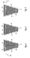
- FIGS. 6 through 8 the effect of changing the position of the injected cooling air 44 by the upstream and downstream movement of the cover plate 32 is shown.
- Vectoring of the primary stream 20 is accomplished by the injection of the cooling air 44 through the vector openings 30 and into the exhaust passage 24.
- the cooling air 44 creates a barrier, or blocked area schematically shown by dashed lines 45 across the trailing edge 38, that restricts the flow of the primary stream 20.
- the resistance to airflow in the blocked areas 45 causes the primary stream to move toward areas of less resistance.
- the primary stream 20 reacts by bending or flowing to the area of least resistance where no barrier to flow exists.
- the cooling air 44 injected into the exhaust passage 24 creates the barrier by generating high-pressure regions 50.
- the high-pressure regions 50 create the resistance to the flow of the primary stream 20.
- the resistance caused by the high-pressure regions 50 does not prevent flow, but provides a resistance to flow of the primary stream that redirects a substantial portion of the primary stream 20.
- the corresponding region of the nozzle does not include cooling air 44 and therefore provides less resistance to flow than the high-pressure region 50.
- the primary stream 20 flows unimpeded through such a region.
- a substantially equal amount of cooling air 44 passes through each of the first and second vector openings 30 on opposing sides of the nozzle. This results in substantially equal amounts of primary stream 20 being redirected toward the center of the exhaust nozzle 22 that in turn results in no directional vectoring of the primary stream 20.
- the cooling air 44 passes through the first or left vector opening 30. This results in the primary stream 20 being redirected toward the opposite side of the exhaust nozzle 22. In the second or right vectoring position, the cooling air 44 passes through the second or right vector opening 30. This results in the primary stream 20 being redirected toward the opposite side of the exhaust nozzle 22.
- the configuration of the vectoring openings 30 with respect to the plate openings 35 allows for redirection of the primary stream 20 while maintaining the same flow area.
- the movement of the cover plate 32 is a small linear movement via the actuator arm 33 that is attached to the cover plate 32 and actuated by the drive 46.
- the small linear movement of the cover plate 32 allows for faster changes in vectoring control and a more responsive control system.
- Cooling air 44 selectively exiting the vector openings 30 generate the high-pressure region 50 to one side of the exhaust nozzle assembly 22 thereby directing a majority of the flow of the primary stream 20 to exit one side of the exhaust nozzle assembly 22. This directional control of the primary stream 20 provides the desired directional thrust utilized to enhance manoeuvrability of the aircraft.
- the exhaust nozzle assembly 122 includes inner duct wall 25 and outer duct wall 26 spaced apart from each other to define cooling air passage 40.
- the exhaust nozzle assembly 122 includes vector openings 130,131 that inject cooling air 44 into the exhaust passage 24.
- the angle of introduction typically is normal to the primary stream 20 but alternative angles are also contemplated by the present disclosure.
- the vector openings 130,131 are selectively sealed or blocked by a cover plate 132.
- the cover plate 132 is movable with respect to the vector openings 130, 131 to adjust the location that cooling air 44 is injected into the primary stream 20.
- An actuator arm 33 is attached to the cover plate 132 and is actuated by a drive 46 for movement of the cover plate 132. While the exemplary embodiment describes the actuator arm 33 and drive 46 for moving the cover plate 132, the present disclosure contemplates alternative drive mechanisms and methods.
- the cover plate 132 moves along the center line C L of the nozzle to selectively seal or open the vector openings 130.
- the vector openings 130 are positioned near the trailing edge 38 to maximize the yaw vectoring effectiveness of the primary stream 20.
- alternative positionings are contemplated by the present disclosure.
- the cover plate 132 has plate openings 135 shaped to maintain the same open area through the vector openings 130.
- the plate openings 135 are positioned along upstream and downstream portions of the cover plate 132.
- the vector openings 130, 131 have non-rectangular shapes and the plate openings 135 have rectangular shapes but function as described above with respect to the embodiment of FIGS. 1 through 8 to change the position of the injected cooling air 44 and thus direct the primary stream 20.
- the circular shape of the vector openings 130, 131 and rectangular plate openings 135 allow for control of the amount of flow area over the range of cover plate positions as well as control of the rate of change of the re-directing of the primary stream 20.
- the exhaust nozzle assembly 222 includes inner duct wall 25 and outer duct wall 26 spaced apart from each other to define cooling air passage 40.
- the exhaust nozzle assembly 222 includes a plurality of vector openings 230, 231 that inject cooling air 44 into the exhaust passage 24.
- the angle of introduction typically is normal to the primary stream 20 but alternative angles are also contemplated by the present disclosure.
- the vector openings 230, 231 are selectively sealed or blocked by a cover plate 132.
- the cover plate 132 is movable with respect to the vector openings 230, 231 to adjust the location that cooling air 44 is injected into the primary stream 20.
- An actuator arm 33 is attached to the cover plate 232 and is actuated by a drive 46 for movement of the cover plate 232. While the exemplary embodiment describes the actuator arm 33 and drive 46 for moving the cover plate 232, the present disclosure contemplates alternative drive mechanisms and methods.
- the cover plate 232 moves along the center line C L of the nozzle to selectively seal or open the vector openings 230, 231.
- the vector openings 230, 231 are positioned near the trailing edge 38 to maximize the yaw vectoring effectiveness of the primary stream 20.
- the cover plate 232 has plate openings 235 shaped to maintain the same open area through the vector openings 230, 231.
- the plate openings 235 are positioned along upstream and downstream portions of the cover plate 232.
- the vector openings 230, 231 have a non-rectangular shape and the plate openings 235 have a rectangular shape but function as described above with respect to the embodiment of FIGS. 1 through 8 to change the position of the injected cooling air 44.
- the trapezoidal shape of the vector openings 230, 231 and rectangular plate openings 235 allow for control of the amount of flow area over the range of cover plate positions as well as control of the rate of change of the re-directing of the primary stream 20.
- cover plates 32, 132 and 232 can be used with various shapes and/or curvatures of nozzle liners.
- the shape and orientation of the vector openings 30, 130, 131, 230, 231 and plate openings 35, 135, 235 can be varied to facilitate the vectoring control and directing of the primary stream 20.
- Smaller vector openings 30,130, 131, 230, 231 can be utilized which facilitates their sealing by cover plates 32,132, 232 to prevent unwanted leakage.
- cooling air 44 as described in this invention is utilized to provide thrust vectoring that enhances movement about a yaw axis.
- present disclosure contemplates positioning of the vector openings 30,130,131, 230, 231 within side walls of the exhaust nozzle assemblies 22, 122, 222 to provide for thrust vectoring that would enhance movement about other axes, such as the pitch and roll axis.
- the constant flow of cooling air 44 through the substantially constant flow area regardless of the position of cover plate 32 is desirable because no variation is encountered by the propulsion system 12.
- the exhaust nozzle assemblies 22,122, 222 of the exemplary embodiments described herein provide fluidic thrust vectoring of the primary stream that enhances aircraft manoeuvrability.
Description
- This invention relates generally to exhaust nozzles for jet engines. More particularly, this invention relates to fluidic vectoring control for an exhaust nozzle.
- A jet engine includes a compressor providing high-pressure air to a combustor. Fuel and air are mixed within the combustor and ignited, resulting in high-speed exhaust gas that drives the turbine of the jet engine. The exhaust gas exits the jet engine through an exhaust nozzle and generates thrust that propels the aircraft. The exhaust nozzle directs the exhaust gas to optimize thrust produced by the jet engine.
- Due to the extreme temperature at which exhaust gases exit through the exhaust nozzle, a layer of cooling air is typically provided to the exhaust nozzle by a plurality of openings within the nozzle liner. The layer of cooling air thermally insulates the surface of the exhaust nozzle from the exhaust gas:
- Aircraft movement, such as, for example, about the yaw axis, can be accomplished through various methods and combinations of methods including control surfaces, such as a rudder, and directing exhaust gas. One method of directing exhaust gas is via movement of the exhaust nozzle. The drawback of movement of the exhaust nozzle is that it requires complicated mechanisms and control systems.
- Another method of directing exhaust gas utilizes high-pressure bleed air directed along different points of the exhaust nozzle. Unfortunately, such a device typically requires complicated tubing and channeling in order to communicate air to the desired location in the exhaust nozzle.
- Thus, there is a need for fluidic vectoring control that is simple, efficient and flexible in its applications to various exhaust nozzles. There is a further need for such a device that allows for quick response time upon actuation.
-
EP 1659282 discloses an exemplary vectoring exhaust nozzle assembly. - Thus, viewed from a first aspect, the invention provides an exhaust nozzle assembly comprising: an exhaust passage for directing a primary stream; an airflow passage for cooling air; a plurality of vector openings in communication with said airflow passage and said exhaust passage for injecting said cooling air into the exhaust passage to vector said primary stream; and a cover plate movable with respect to said vector openings for selectively blocking and unblocking a portion of said flow of cooling air from said airflow passage into said exhaust passage, wherein said vector openings have a total flow area; wherein said total flow area remains substantially constant over an entire range of motion of said cover plate, and wherein said cover plate is configured to move in a straight line along a center line of the exhaust nozzle assembly and has a plurality of plate openings that selectively unblock said portion of said flow of cooling air.
- Viewed from a second aspect, the invention also provides a method of directing an exhaust gas path comprising: providing cooling air to an exhaust nozzle assembly; injecting said cooling air through a plurality of vector openings into a primary stream of said exhaust nozzle assembly; and adjusting a position of said injecting with respect to said primary stream via movement of a cover plate that blocks a portion of flow of said cooling air, wherein said vector openings have a total flow area; wherein said total flow area remains substantially constant over an entire range of motion of said cover plate; wherein said method further comprises moving said cover plate in a straight line along a center line of the exhaust nozzle assembly; and wherein said cover plate has a plurality of plate openings that selectively unblock said portion of said flow of cooling air.
- The exhaust passage may have a trailing edge and the plurality of vector openings may be in proximity to the trailing edge. The size and shape of each of the plurality of vector openings can be equal to the size and shape of each of the plurality of plate openings.
- The plurality of plate openings can be a first set of plate openings and a second set of plate openings, wherein the first set of plate openings is positioned along an upstream portion of the cover and wherein the second set of plate openings is positioned along a downstream portion of the cover. The assembly can also have an actuator arm connected to the cover for selectively moving the cover with respect to the vector opening. The injection of the cooling air into the primary stream may provide yaw vectoring.
- Accordingly, the exhaust nozzle assembly of this invention provides thrust vectoring of the primary stream without complex piping and conduits.
- These and other features of the present invention can be best understood from the following specification and drawings, the following of which is a brief description.
- Other uses and advantages of the present invention will become apparent to those skilled in the art upon reference to the specification and the drawings, in which:
-
Figure 1 is a schematic representation of a jet engine assembly having a nozzle and cover plate in accordance with an exemplary embodiment; -
Figure 2 is a schematic exploded plan view of a nozzle and cover plate used in the assembly ofFigure 1 ; -
Figure 3 is a schematic plan view of the nozzle and cover plate ofFigure 2 in a neutral vectoring position; -
Figure 4 is a schematic plan view of the nozzle and cover plate ofFigure 2 in a first or left vectoring position; -
Figure 5 is a schematic plan view of the nozzle and cover plate ofFigure 2 in a second or right vectoring position; -
Figure 6 is a schematic plan view of the nozzle and cover plate ofFigure 2 in the neutral vectoring position showing a representative gas exhaust path; -
Figure 7 is a schematic plan view of the nozzle and cover plate ofFigure 2 in the left vectoring position showing a representative gas exhaust path; -
Figure 8 is a schematic plan view of the nozzle and cover plate ofFigure 2 in the right vectoring position showing a representative gas exhaust path; -
Figure 9 is a schematic exploded plan view of a nozzle and cover plate in accordance with another exemplary embodiment; and -
Figure 10 is a schematic exploded plan view of a nozzle and cover plate in accordance with another exemplary embodiment. - Referring to
FIG. 1 , ajet engine assembly 10 is shown and includes a propulsion system 12 that intakes air from aninlet 18 mixes it with fuel and generates aprimary stream 20 that provides a desired thrust force. Theprimary stream 20 exits through anexhaust nozzle assembly 22 that includes anexhaust passage 24. Theexhaust passage 24 includes anozzle throat 14 for accelerating theprimary stream 20. Theexhaust nozzle assembly 22 provides for the fluidic thrust vectoring of theprimary stream 20 to enhance aircraft manoeuvrability. - Referring to
FIGS. 1 and2 , theexhaust nozzle assembly 22 is shown.Exhaust nozzle assembly 22 has atrailing edge 38 and is a converging/diverging nozzle. Theexhaust passage 24 necks down to a smallest cross-sectional area at thenozzle throat 14, and increases in cross-sectional area from thenozzle throat 14 to thetrailing edge 38. The particular shape and dimensions of thenozzle assembly 22 can be varied to obtain the performance desired. - The
exhaust nozzle assembly 22 includes aninner duct wall 25 and anouter duct wall 26 spaced apart from each other to define acooling air passage 40. Thecooling air passage 40 supplies cooling air 44 (shown inFIGS 3 through 5 ) that can be used to direct the exhaust gas flow path as will be described later in greater detail. Theinner duct wall 25 can include a plurality of cooling holes (not shown) which when supplied withcooling air 44 viaair passage 40 creates an insulating layer of air along theinner duct wall 25. Thecooling air 44 insulates theinner duct wall 25 from the high temperature of theprimary stream 20. The volume and rate ofcooling air 44 may be fixed for all operating parameters of the propulsion system 12 thereby preventing undesirable fluctuations in propulsion system 12 performance. - The
exhaust nozzle assembly 22 includes a plurality ofvector openings 30 that injectcooling air 44 into theexhaust passage 24. In this exemplary embodiment, there are first andsecond vector openings 30 but as will be seen in other exemplary embodiments, the present disclosure contemplates the use of other numbers of vector openings. The angle of introduction typically is normal to theprimary stream 20 but alternative angles are also contemplated by the present disclosure. Thevector openings 30 are selectively sealed or blocked by acover plate 32. Thecover plate 32 is movable with respect to thevector openings 30 to adjust the location that coolingair 44 is injected into theprimary stream 20. Anactuator arm 33 is attached to thecover plate 32 and is actuated by adrive 46 for movement of thecover plate 32. While the exemplary embodiment describes theactuator arm 33 and drive 46 for moving thecover plate 32, the present disclosure contemplates alternative drive mechanisms and methods. - As shown in
FIGS. 3 through 5 , thecover plate 32 moves along the center line CL of the nozzle to selectively seal or open thevector openings 30. However, alternative positionings are contemplated by the present disclosure. Preferably, thevector openings 30 are positioned near or in proximity to the trailingedge 38 to maximize the yaw vectoring effectiveness of theprimary stream 20. Thecover plate 32 hasplate openings 35 that have substantially the same size and shape as thevector openings 30. Theplate openings 35 are equal in number to thevector openings 30 but are positioned along upstream and downstream portions of thecover plate 32 for reasons which will now be described in greater detail. - In use, the
vector openings 30 and theplate openings 35 establish a constant controlled flow area, the flow area of which is maintained constant by the interaction between a size and shape of each of thevector openings 30 and a size and shape of each of theplate openings 35. - As shown in
FIG. 3 , thecover plate 32 can be positioned in a neutral vectoring position so that the amount ofvector opening 30, i.e., the flow area, is equal in both the first and second vector openings. The neutral vectoring position is accomplished by positioning theplate openings 35 so as to unblock approximately half of eachvector opening 30. - As shown in
FIG. 4 , as the cover plate is moved downstream along the center line CL as shown byarrow 300, thefirst vector opening 30 is further opened or unblocked while the second vector opening is closed or blocked. The amount of flow area in this first or left vectoring position is substantially equal to the amount of flow area in the neutral vectoring position. As thecover plate 32 is moving along the centerline CL, the amount of flow area remains substantially constant but the injection position of the coolingair 44 with respect to thegas stream 20 is being changed. - As shown in
FIG. 5 , as the cover plate is moved upstream along the center line CL as shown by thearrow 301, the second vector opening 30 is further opened or unblocked while the first vector opening is closed or blocked. The amount of flow area in this second or right vectoring position is substantially equal to the amount of flow area in the neutral vectoring position, which is also substantially equal to the amount of flow area in the first or left vectoring position. As thecover plate 32 is moving along the centerline CL, the amount of flow area remains substantially constant but the injection position of the coolingair 44 with respect to thegas stream 20 is being changed. - Referring to
FIGS. 6 through 8 , the effect of changing the position of the injected coolingair 44 by the upstream and downstream movement of thecover plate 32 is shown. Vectoring of theprimary stream 20 is accomplished by the injection of the coolingair 44 through thevector openings 30 and into theexhaust passage 24. The coolingair 44 creates a barrier, or blocked area schematically shown by dashedlines 45 across the trailingedge 38, that restricts the flow of theprimary stream 20. The resistance to airflow in the blockedareas 45 causes the primary stream to move toward areas of less resistance. Theprimary stream 20 reacts by bending or flowing to the area of least resistance where no barrier to flow exists. The coolingair 44 injected into theexhaust passage 24 creates the barrier by generating high-pressure regions 50. The high-pressure regions 50 create the resistance to the flow of theprimary stream 20. The resistance caused by the high-pressure regions 50 does not prevent flow, but provides a resistance to flow of the primary stream that redirects a substantial portion of theprimary stream 20. - When one of the
vector openings 30 is blocked or substantially blocked, the corresponding region of the nozzle does not include coolingair 44 and therefore provides less resistance to flow than the high-pressure region 50. Theprimary stream 20 flows unimpeded through such a region. In the neutral vectoring position, a substantially equal amount of coolingair 44 passes through each of the first andsecond vector openings 30 on opposing sides of the nozzle. This results in substantially equal amounts ofprimary stream 20 being redirected toward the center of theexhaust nozzle 22 that in turn results in no directional vectoring of theprimary stream 20. - In the first or left vectoring position, the cooling
air 44 passes through the first or leftvector opening 30. This results in theprimary stream 20 being redirected toward the opposite side of theexhaust nozzle 22. In the second or right vectoring position, the coolingair 44 passes through the second orright vector opening 30. This results in theprimary stream 20 being redirected toward the opposite side of theexhaust nozzle 22. - As described above, a full range of vectoring is available by movement of the
cover plate 32. The configuration of the vectoringopenings 30 with respect to theplate openings 35 allows for redirection of theprimary stream 20 while maintaining the same flow area. The movement of thecover plate 32 is a small linear movement via theactuator arm 33 that is attached to thecover plate 32 and actuated by thedrive 46. The small linear movement of thecover plate 32 allows for faster changes in vectoring control and a more responsive control system. Coolingair 44 selectively exiting thevector openings 30 generate the high-pressure region 50 to one side of theexhaust nozzle assembly 22 thereby directing a majority of the flow of theprimary stream 20 to exit one side of theexhaust nozzle assembly 22. This directional control of theprimary stream 20 provides the desired directional thrust utilized to enhance manoeuvrability of the aircraft. - Referring to
FIG. 9 , another exemplary embodiment of the nozzle assembly is shown and generally represented byreference numeral 122. Similar features as the exemplary embodiment ofFIGS. 1 through 8 , are represented by the same reference numerals. Theexhaust nozzle assembly 122 includesinner duct wall 25 andouter duct wall 26 spaced apart from each other to define coolingair passage 40. - The
exhaust nozzle assembly 122 includes vector openings 130,131 that inject coolingair 44 into theexhaust passage 24. In this exemplary embodiment, there are a first set ofvector openings 130 and a second set ofvector openings 131 but as will be seen in other exemplary embodiments, the present disclosure contemplates the use of other numbers of vector openings. The angle of introduction typically is normal to theprimary stream 20 but alternative angles are also contemplated by the present disclosure. The vector openings 130,131 are selectively sealed or blocked by acover plate 132. Thecover plate 132 is movable with respect to thevector openings air 44 is injected into theprimary stream 20. Anactuator arm 33 is attached to thecover plate 132 and is actuated by adrive 46 for movement of thecover plate 132. While the exemplary embodiment describes theactuator arm 33 and drive 46 for moving thecover plate 132, the present disclosure contemplates alternative drive mechanisms and methods. - The
cover plate 132 moves along the center line CL of the nozzle to selectively seal or open thevector openings 130. Preferably, thevector openings 130 are positioned near the trailingedge 38 to maximize the yaw vectoring effectiveness of theprimary stream 20. However, alternative positionings are contemplated by the present disclosure. Thecover plate 132 hasplate openings 135 shaped to maintain the same open area through thevector openings 130. Theplate openings 135 are positioned along upstream and downstream portions of thecover plate 132. Thevector openings plate openings 135 have rectangular shapes but function as described above with respect to the embodiment ofFIGS. 1 through 8 to change the position of the injected coolingair 44 and thus direct theprimary stream 20. The circular shape of thevector openings rectangular plate openings 135 allow for control of the amount of flow area over the range of cover plate positions as well as control of the rate of change of the re-directing of theprimary stream 20. - Referring to
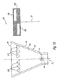
FIG. 10 , another exemplary embodiment of the nozzle assembly is shown and generally represented byreference numeral 222. Similar features as the exemplary embodiment ofFIGS 1 through 8 , are represented by the same reference numerals. Theexhaust nozzle assembly 222 includesinner duct wall 25 andouter duct wall 26 spaced apart from each other to define coolingair passage 40. - The
exhaust nozzle assembly 222 includes a plurality ofvector openings air 44 into theexhaust passage 24. In this exemplary embodiment, there are a first set ofvector openings 230 and a second set ofvector openings 231 but as will be seen in other exemplary embodiments, the present disclosure contemplates the use of other numbers of vector openings. The angle of introduction typically is normal to theprimary stream 20 but alternative angles are also contemplated by the present disclosure. Thevector openings cover plate 132. Thecover plate 132 is movable with respect to thevector openings air 44 is injected into theprimary stream 20. Anactuator arm 33 is attached to thecover plate 232 and is actuated by adrive 46 for movement of thecover plate 232. While the exemplary embodiment describes theactuator arm 33 and drive 46 for moving thecover plate 232, the present disclosure contemplates alternative drive mechanisms and methods. - The
cover plate 232 moves along the center line CL of the nozzle to selectively seal or open thevector openings vector openings edge 38 to maximize the yaw vectoring effectiveness of theprimary stream 20. Thecover plate 232 hasplate openings 235 shaped to maintain the same open area through thevector openings plate openings 235 are positioned along upstream and downstream portions of thecover plate 232. Thevector openings plate openings 235 have a rectangular shape but function as described above with respect to the embodiment ofFIGS. 1 through 8 to change the position of the injected coolingair 44. The trapezoidal shape of thevector openings rectangular plate openings 235 allow for control of the amount of flow area over the range of cover plate positions as well as control of the rate of change of the re-directing of theprimary stream 20. - In the above exemplary embodiments,
cover plates vector openings plate openings primary stream 20. Smaller vector openings 30,130, 131, 230, 231 can be utilized which facilitates their sealing by cover plates 32,132, 232 to prevent unwanted leakage. - The injection of cooling
air 44 as described in this invention is utilized to provide thrust vectoring that enhances movement about a yaw axis. Although the present disclosure contemplates positioning of the vector openings 30,130,131, 230, 231 within side walls of theexhaust nozzle assemblies air 44 through the substantially constant flow area regardless of the position ofcover plate 32 is desirable because no variation is encountered by the propulsion system 12. The exhaust nozzle assemblies 22,122, 222 of the exemplary embodiments described herein provide fluidic thrust vectoring of the primary stream that enhances aircraft manoeuvrability. - It should also be noted that the terms "first", "second", "right", and "left", and the like, are used herein to describe various elements. These modifiers do not imply a spatial, sequential, or hierarchical order to the modified elements unless specifically stated.
- While the instant disclosure has been described with reference to one or more exemplary embodiments, it will be understood by those skilled in the art that various changes may be made and equivalents may be substituted for elements thereof without departing from the scope thereof. In addition, many modifications may be made to adapt a particular situation or material to the teachings of the disclosure without departing from the scope thereof. Therefore, it is intended that the disclosure not be limited to the particular embodiment(s) disclosed as the best mode contemplated for carrying out this invention, but that the invention will include all embodiments falling within the scope of the appended claims and their equivalents.
Claims (7)
- An exhaust nozzle assembly (22) comprising:an exhaust passage (24) for directing a primary stream (20);an airflow passage (40) for cooling air (44);a plurality of vector openings (30; 130, 131; 230, 231) in communication with said airflow passage (40) and said exhaust passage (24) for injecting said cooling air into the exhaust passage (24) to vector said primary stream (20); anda cover plate (32; 132; 232) movable with respect to said vector openings (30; 130; 131; 230; 231) for selectively blocking and unblocking a portion of said flow of cooling air from said airflow passage (40) into said exhaust passage (24),wherein said vector openings (30; 130, 131; 230; 231) have a total flow area; andwherein said total flow area remains substantially constant over an entire range of motion of said cover plate (32; 132; 232),characterised in that said cover plate (32; 132; 232) is configured to move in a straight line along a center line (CL) of the exhaust nozzle assembly (22) and has a plurality of plate openings (35; 135; 235) that selectively unblock said portion of said flow of cooling air (44).
- The assembly of claim 1, wherein said exhaust passage (24) comprises a trailing edge (38) and said vector openings (30; 130, 131; 230; 231 are in proximity to said trailing edge (38).
- The assembly of claim 1 or 2, wherein a constant controlled flow area is established by the interaction between the size and shape of each of said plurality of vector openings (130, 131; 230, 231) with the size and shape of each of said plurality of plate openings (135; 235).
- The assembly of any preceding claim, wherein said plurality of plate openings (135; 235) is a first set of plate openings and a second set of plate openings, wherein said first set of plate openings is positioned along an upstream portion of said cover (132; 232) and wherein said second set of plate openings is positioned along a downstream portion of said cover (132; 232).
- The assembly of any preceding claim, further comprising an actuator arm (33) connected to said cover plate (32; 132; 232) for selectively moving said cover plate with respect to said vector openings (30; 130, 131; 230, 231).
- A method of directing an exhaust gas path comprising:providing cooling air (44) to an exhaust nozzle assembly (22);injecting said cooling air (44) through a plurality of vector openings (30; 130, 131; 230, 231) into a primary stream (20) of said exhaust nozzle assembly (22); andadjusting a position of said injecting with respect to said primary stream (20) via movement of a cover plate (32; 132; 232) that blocks a portion of flow of said cooling air (44), wherein said vector openings (30; 130; 131; 230; 231) have a total flow area; and wherein said total flow area remains substantially constant over an entire range of motion of said cover plate (32; 132; 232) ;characterised in that said method further comprises moving said cover plate (32; 132; 232)in a straight line along a center line (CL) of the exhaust nozzle assembly (22), and in that said cover plate (32; 132; 232) has a plurality of plate openings (35; 135; 235) that selectively unblock said portion of said flow of cooling air (44).
- The method of claim 6, wherein said injecting of said cooling air (44) into said primary stream (20) provides yaw vectoring.
Applications Claiming Priority (1)
| Application Number | Priority Date | Filing Date | Title |
|---|---|---|---|
| US11/809,297 US8096104B2 (en) | 2007-05-31 | 2007-05-31 | Fluidic vectoring for exhaust nozzle |
Publications (3)
| Publication Number | Publication Date |
|---|---|
| EP1998035A2 EP1998035A2 (en) | 2008-12-03 |
| EP1998035A3 EP1998035A3 (en) | 2012-02-08 |
| EP1998035B1 true EP1998035B1 (en) | 2013-03-06 |
Family
ID=39687840
Family Applications (1)
| Application Number | Title | Priority Date | Filing Date |
|---|---|---|---|
| EP08251894A Active EP1998035B1 (en) | 2007-05-31 | 2008-05-30 | Fluidic vectoring for exhaust nozzle |
Country Status (2)
| Country | Link |
|---|---|
| US (1) | US8096104B2 (en) |
| EP (1) | EP1998035B1 (en) |
Families Citing this family (7)
| Publication number | Priority date | Publication date | Assignee | Title |
|---|---|---|---|---|
| US9745962B2 (en) | 2014-03-10 | 2017-08-29 | X Development Llc | Radiator configuration for a flying wind turbine that passively controls airflow |
| US9964069B2 (en) | 2015-06-29 | 2018-05-08 | United Technologies Corporation | Exhaust nozzle control for a gas turbine engine |
| DE102015014529B3 (en) * | 2015-11-11 | 2016-09-29 | Ac Aircontrols Gmbh | Device for mixing and dosing at least two gases |
| US10807703B2 (en) * | 2018-07-19 | 2020-10-20 | General Electric Company | Control system for an aircraft |
| CN110259608B (en) * | 2019-06-19 | 2020-05-15 | 湖北三江航天红峰控制有限公司 | Solid attitude and orbit control engine nozzle blanking cap |
| CN115807720A (en) * | 2022-11-22 | 2023-03-17 | 西北工业大学 | Variable thrust expansion compensation rocket engine based on vortex valve and plug type spray pipe |
| CN116202774B (en) * | 2023-04-28 | 2023-08-18 | 中国航发四川燃气涡轮研究院 | Exhaust full-containment structure for high-altitude bench vector test |
Family Cites Families (21)
| Publication number | Priority date | Publication date | Assignee | Title |
|---|---|---|---|---|
| US3354645A (en) * | 1966-01-03 | 1967-11-28 | United Aircraft Corp | Method and apparatus for producing a non-axial thrust vector |
| US3749317A (en) * | 1971-03-01 | 1973-07-31 | Mc Donnell Douglas Corp | Thrust vector control system |
| US3794063A (en) * | 1973-01-23 | 1974-02-26 | Thermo King Corp | Refrigerant throttling valve |
| US3859787A (en) * | 1974-02-04 | 1975-01-14 | Gen Motors Corp | Combustion apparatus |
| US5687907A (en) * | 1987-12-18 | 1997-11-18 | United Technologies Corporation | Yaw and pitch thrust vectoring nozzle |
| US5619851A (en) * | 1989-02-08 | 1997-04-15 | United Technologies Corporation | Rocket nozzle for a rocket engine |
| US5427146A (en) * | 1994-06-27 | 1995-06-27 | Bakken; Gary M. | Linearly adjustable fluid damper |
| US5706650A (en) * | 1995-08-09 | 1998-01-13 | United Technologies Corporation | Vectoring nozzle using injected high pressure air |
| IL116668A (en) * | 1996-01-03 | 1998-12-06 | Univ Ramot | Apparatus and method for controlling the motion of a solid body or fluid stream |
| US6112513A (en) * | 1997-08-05 | 2000-09-05 | Lockheed Martin Corporation | Method and apparatus of asymmetric injection at the subsonic portion of a nozzle flow |
| US5996936A (en) * | 1997-09-29 | 1999-12-07 | General Electric Company | Fluidic throat exhaust nozzle |
| US6145299A (en) * | 1998-11-19 | 2000-11-14 | Fasano; Timothy | Rocket engine |
| US6298658B1 (en) * | 1999-12-01 | 2001-10-09 | Williams International Co., L.L.C. | Multi-stable thrust vectoring nozzle |
| US6354074B1 (en) * | 2000-05-24 | 2002-03-12 | Lockheed Martin Corp. | Hybrid injection thrust vector control |
| US6336319B1 (en) * | 2000-05-26 | 2002-01-08 | General Electric Company | Fluidic nozzle control system |
| FR2860045B1 (en) * | 2003-09-24 | 2006-01-06 | Snecma Moteurs | VENTILATION SYSTEM FOR A DIVERGENT CONVERGENT EJECTION TUBE |
| US7155898B2 (en) * | 2004-04-13 | 2007-01-02 | Aerojet-General Corporation | Thrust vector control system for a plug nozzle rocket engine |
| US7481038B2 (en) | 2004-10-28 | 2009-01-27 | United Technologies Corporation | Yaw vectoring for exhaust nozzle |
| SE527829C2 (en) * | 2004-11-05 | 2006-06-13 | Volvo Aero Corp | Outlet nozzle for a jet engine and method for controlling a gas flow from the jet engine |
| GB0503874D0 (en) * | 2005-02-24 | 2005-04-06 | Rolls Royce Plc | Fluid vectoring nozzle |
| US7509797B2 (en) * | 2005-04-29 | 2009-03-31 | General Electric Company | Thrust vectoring missile turbojet |
-
2007
- 2007-05-31 US US11/809,297 patent/US8096104B2/en active Active
-
2008
- 2008-05-30 EP EP08251894A patent/EP1998035B1/en active Active
Also Published As
| Publication number | Publication date |
|---|---|
| EP1998035A3 (en) | 2012-02-08 |
| EP1998035A2 (en) | 2008-12-03 |
| US20080295481A1 (en) | 2008-12-04 |
| US8096104B2 (en) | 2012-01-17 |
Similar Documents
| Publication | Publication Date | Title |
|---|---|---|
| EP1998035B1 (en) | Fluidic vectoring for exhaust nozzle | |
| EP1659282B1 (en) | Yaw vectoring for exhaust nozzle | |
| US5706650A (en) | Vectoring nozzle using injected high pressure air | |
| JP5241215B2 (en) | Passive guidance system and method for aircraft engine nozzle fluids | |
| US8371104B2 (en) | System and apparatus for vectoring nozzle exhaust plume from a nozzle | |
| US6634595B2 (en) | Method and apparatus for controlling aircraft inlet air flow | |
| US6070407A (en) | Ducted fan gas turbine engine with variable area fan duct nozzle | |
| US6679048B1 (en) | Apparatus and method for controlling primary fluid flow using secondary fluid flow injection | |
| JP4672747B2 (en) | Rocket nozzle and rocket engine combustion gas flow control method | |
| EP1726811B1 (en) | System and method for cooling lateral edge regions of a divergent seal of an axisymmetric nozzle | |
| EP2971739B1 (en) | Gas turbine engine flow duct having two rows of integrated heat exchangers | |
| EP2108806B1 (en) | Gas turbine engine systems involving variable nozzles with sliding doors | |
| US5833139A (en) | Single variable flap exhaust nozzle | |
| US8015794B2 (en) | Variable area flow duct employing secondary flows, and method therefor | |
| US20100037587A1 (en) | Turbojet Nacelle Equipped With Means For Reducing The Noise Produced By Said Turbojet | |
| WO2006028516B1 (en) | Thrust vector control system for a plug nozzle rocket engine | |
| US6000635A (en) | Exhaust nozzle for a turbojet engine | |
| RU2346175C2 (en) | Turbojet engine convergent-divergent supersonic jet nozzle | |
| JPS6339781B2 (en) | ||
| US4767055A (en) | Method and linkage for positioning a convergent flap and coaxial arc valve | |
| US10781756B2 (en) | Active tip clearance control system for gas turbine engine | |
| US7464535B2 (en) | Rocket motor nozzle throat area control system and method | |
| JP4885301B2 (en) | Rocket nozzle and rocket engine combustion gas flow control method | |
| US6453937B1 (en) | Hot gas valve construction for reducing thermal shock effects | |
| US6164059A (en) | Multi-expansion ejector nozzle with diverging walls |
Legal Events
| Date | Code | Title | Description |
|---|---|---|---|
| PUAI | Public reference made under article 153(3) epc to a published international application that has entered the european phase |
Free format text: ORIGINAL CODE: 0009012 |
|
| AK | Designated contracting states |
Kind code of ref document: A2 Designated state(s): AT BE BG CH CY CZ DE DK EE ES FI FR GB GR HR HU IE IS IT LI LT LU LV MC MT NL NO PL PT RO SE SI SK TR |
|
| AX | Request for extension of the european patent |
Extension state: AL BA MK RS |
|
| PUAL | Search report despatched |
Free format text: ORIGINAL CODE: 0009013 |
|
| AK | Designated contracting states |
Kind code of ref document: A3 Designated state(s): AT BE BG CH CY CZ DE DK EE ES FI FR GB GR HR HU IE IS IT LI LT LU LV MC MT NL NO PL PT RO SE SI SK TR |
|
| AX | Request for extension of the european patent |
Extension state: AL BA MK RS |
|
| RIC1 | Information provided on ipc code assigned before grant |
Ipc: F02K 9/82 20060101ALI20120103BHEP Ipc: F02K 1/82 20060101ALI20120103BHEP Ipc: F02K 1/28 20060101ALI20120103BHEP Ipc: F02K 1/38 20060101ALI20120103BHEP Ipc: F02K 1/00 20060101AFI20120103BHEP |
|
| 17P | Request for examination filed |
Effective date: 20120803 |
|
| AKX | Designation fees paid |
Designated state(s): DE GB |
|
| GRAP | Despatch of communication of intention to grant a patent |
Free format text: ORIGINAL CODE: EPIDOSNIGR1 |
|
| GRAS | Grant fee paid |
Free format text: ORIGINAL CODE: EPIDOSNIGR3 |
|
| GRAA | (expected) grant |
Free format text: ORIGINAL CODE: 0009210 |
|
| AK | Designated contracting states |
Kind code of ref document: B1 Designated state(s): DE GB |
|
| REG | Reference to a national code |
Ref country code: GB Ref legal event code: FG4D |
|
| REG | Reference to a national code |
Ref country code: DE Ref legal event code: R096 Ref document number: 602008022683 Country of ref document: DE Effective date: 20130425 |
|
| PLBE | No opposition filed within time limit |
Free format text: ORIGINAL CODE: 0009261 |
|
| STAA | Information on the status of an ep patent application or granted ep patent |
Free format text: STATUS: NO OPPOSITION FILED WITHIN TIME LIMIT |
|
| 26N | No opposition filed |
Effective date: 20131209 |
|
| REG | Reference to a national code |
Ref country code: DE Ref legal event code: R097 Ref document number: 602008022683 Country of ref document: DE Effective date: 20131209 |
|
| REG | Reference to a national code |
Ref country code: DE Ref legal event code: R082 Ref document number: 602008022683 Country of ref document: DE Representative=s name: SCHMITT-NILSON SCHRAUD WAIBEL WOHLFROM PATENTA, DE |
|
| REG | Reference to a national code |
Ref country code: DE Ref legal event code: R082 Ref document number: 602008022683 Country of ref document: DE Representative=s name: SCHMITT-NILSON SCHRAUD WAIBEL WOHLFROM PATENTA, DE Ref country code: DE Ref legal event code: R081 Ref document number: 602008022683 Country of ref document: DE Owner name: UNITED TECHNOLOGIES CORP. (N.D.GES.D. STAATES , US Free format text: FORMER OWNER: UNITED TECHNOLOGIES CORP., HARTFORD, CONN., US |
|
| REG | Reference to a national code |
Ref country code: DE Ref legal event code: R081 Ref document number: 602008022683 Country of ref document: DE Owner name: RAYTHEON TECHNOLOGIES CORPORATION (N.D.GES.D.S, US Free format text: FORMER OWNER: UNITED TECHNOLOGIES CORP. (N.D.GES.D. STAATES DELAWARE), FARMINGTON, CONN., US |
|
| P01 | Opt-out of the competence of the unified patent court (upc) registered |
Effective date: 20230519 |
|
| PGFP | Annual fee paid to national office [announced via postgrant information from national office to epo] |
Ref country code: DE Payment date: 20230419 Year of fee payment: 16 |
|
| PGFP | Annual fee paid to national office [announced via postgrant information from national office to epo] |
Ref country code: GB Payment date: 20230420 Year of fee payment: 16 |