EP2000847A2 - Adaptive polarization adjustment apparatus for controlling polarization of light inputted to polarization-maintaining waveguide components - Google Patents
Adaptive polarization adjustment apparatus for controlling polarization of light inputted to polarization-maintaining waveguide components Download PDFInfo
- Publication number
- EP2000847A2 EP2000847A2 EP08162506A EP08162506A EP2000847A2 EP 2000847 A2 EP2000847 A2 EP 2000847A2 EP 08162506 A EP08162506 A EP 08162506A EP 08162506 A EP08162506 A EP 08162506A EP 2000847 A2 EP2000847 A2 EP 2000847A2
- Authority
- EP
- European Patent Office
- Prior art keywords
- polarization
- unit
- control apparatus
- wavelength
- waveguide component
- Prior art date
- Legal status (The legal status is an assumption and is not a legal conclusion. Google has not performed a legal analysis and makes no representation as to the accuracy of the status listed.)
- Granted
Links
Images


Classifications
-
- H—ELECTRICITY
- H04—ELECTRIC COMMUNICATION TECHNIQUE
- H04B—TRANSMISSION
- H04B10/00—Transmission systems employing electromagnetic waves other than radio-waves, e.g. infrared, visible or ultraviolet light, or employing corpuscular radiation, e.g. quantum communication
- H04B10/25—Arrangements specific to fibre transmission
- H04B10/2507—Arrangements specific to fibre transmission for the reduction or elimination of distortion or dispersion
- H04B10/2572—Arrangements specific to fibre transmission for the reduction or elimination of distortion or dispersion due to forms of polarisation-dependent distortion other than PMD
-
- G—PHYSICS
- G02—OPTICS
- G02F—OPTICAL DEVICES OR ARRANGEMENTS FOR THE CONTROL OF LIGHT BY MODIFICATION OF THE OPTICAL PROPERTIES OF THE MEDIA OF THE ELEMENTS INVOLVED THEREIN; NON-LINEAR OPTICS; FREQUENCY-CHANGING OF LIGHT; OPTICAL LOGIC ELEMENTS; OPTICAL ANALOGUE/DIGITAL CONVERTERS
- G02F1/00—Devices or arrangements for the control of the intensity, colour, phase, polarisation or direction of light arriving from an independent light source, e.g. switching, gating or modulating; Non-linear optics
- G02F1/01—Devices or arrangements for the control of the intensity, colour, phase, polarisation or direction of light arriving from an independent light source, e.g. switching, gating or modulating; Non-linear optics for the control of the intensity, phase, polarisation or colour
- G02F1/0136—Devices or arrangements for the control of the intensity, colour, phase, polarisation or direction of light arriving from an independent light source, e.g. switching, gating or modulating; Non-linear optics for the control of the intensity, phase, polarisation or colour for the control of polarisation, e.g. state of polarisation [SOP] control, polarisation scrambling, TE-TM mode conversion or separation
-
- G—PHYSICS
- G02—OPTICS
- G02F—OPTICAL DEVICES OR ARRANGEMENTS FOR THE CONTROL OF LIGHT BY MODIFICATION OF THE OPTICAL PROPERTIES OF THE MEDIA OF THE ELEMENTS INVOLVED THEREIN; NON-LINEAR OPTICS; FREQUENCY-CHANGING OF LIGHT; OPTICAL LOGIC ELEMENTS; OPTICAL ANALOGUE/DIGITAL CONVERTERS
- G02F1/00—Devices or arrangements for the control of the intensity, colour, phase, polarisation or direction of light arriving from an independent light source, e.g. switching, gating or modulating; Non-linear optics
- G02F1/01—Devices or arrangements for the control of the intensity, colour, phase, polarisation or direction of light arriving from an independent light source, e.g. switching, gating or modulating; Non-linear optics for the control of the intensity, phase, polarisation or colour
- G02F1/0121—Operation of devices; Circuit arrangements, not otherwise provided for in this subclass
- G02F1/0123—Circuits for the control or stabilisation of the bias voltage, e.g. automatic bias control [ABC] feedback loops
Definitions
- This invention relates to the control apparatus for controlling the polarization of light inputted to polarization-maintaining (PM) waveguide components, in particular, to highly nonlinear polarization-maintaining waveguide components.
- PM polarization-maintaining
- waveguide components used in optical transmission systems have polarization-dependent, more specifically polarization maintaining, characteristics and thus require the coupling of the input light into a principal axis of polarization.
- polarization-maintaining components are nonlinear optical waveguides, such as small-effective area microstructured fibers and semiconductor-based components utilizing sub-band transitions, which enable all-optical signal processing at ultra-high speeds, e.g., wavelength conversion, all-optical 2R and 3R regeneration, and supercontinuum generation.
- the capability of coupling the optical power into one of the two principal axes of polarization-maintaining components in a precisely controllable way becomes of utmost importance.
- a static linear input polarization e.g., light originating from a laser source
- the waveguide device e.g. , a modulator
- PMF polarization maintaining fiber
- a polarization controller (PC) is used to transfer the state of polarization of the light source into a linear polarization at the input of the waveguide.
- a Q(uarter)/H(alf)/Q(uarter) lambda polarization controller comprising a ⁇ /4-, a ⁇ /2-, and a ⁇ /4-waveplate, with adjustable relative orientation of their principal axes of polarization, which allows the transformation of an arbitrary state of polarization into another arbitrary state of polarization, has to be adjusted such that the polarization of the light becomes linear at the PM-waveguide input. If properly aligned PM-components are used between PC and PM-waveguide it is sufficient to use a Q/H lambda PC.
- the ⁇ /4-waveplate allows transforming an arbitrary elliptic polarization into a linear polarization and the ⁇ /2-waveplate allows rotating this linear polarization state to an arbitrary angle.
- the state of polarization usually changes over time because of a change of temperature or stress on the optical fiber.
- One way to deal with such a non-static state of the input polarization to a waveguide component which has polarization-dependent characteristics is to apply a polarization diversity scheme.
- the two polarization components are separated by a polarization beam splitter (PBS) and treated independently such that the device characteristics become virtually polarization-independent.
- PBS polarization beam splitter
- this scheme usually is not suitable for all-optical signal processing applications, which employ nonlinear effects proportional to the signal power, because it is uncertain how the signal power is distributed between the two principal axes of polarizations and because nonlinear effects are proportional to the input power.
- a second way that is also compatible with all-optical signal processing applications is the adaptive adjustment of the input polarization by means of a polarization controller before the PM-waveguide such that all the signal light is coupled into one principal axis of the PM-waveguide.
- a commonly used approach is to place a PBS after the Q/H PC.
- One port is used to supply a linear input polarization to the PM-waveguide component and the other port is used for monitoring purposes.
- the PCs can adaptively adjust the polarization of input light such that all the power passes through the PBS.
- the two components In order to couple the thus obtained linear polarization at the output of the PBS into a principal axis of the waveguide (PM-waveguide), the two components have to be connected by PM-components. Another option is to use non-PM components. Assuming that the polarization transfer function of these components does not change over time, a static H/Q PC can be used after the PBS.
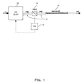
- Fig. 1 and Fig. 2 show conventional control apparatus of polarization.
- Fig. 1 one example of conventional polarization control apparatus is shown.
- the light with arbitrary polarization is inputted to PC 10.
- the polarization of the inputted light is adjusted by PC 10 and the adjusted light is inputted to a polarization maintaining fiber 12 and propagates in the polarization maintaining fiber 12 to be inputted to PBS 11.
- PBS 11 a part of the adjusted light with one polarization is sent through and the other part of the adjusted light with another polarization orthogonal to the one polarization is dropped to PD 13.
- the PD 13 detects the power of the dropped light and feeds it back to PC 10 to minimize the power of the dropped light by changing the state of polarization of the input light to PC 10.
- the light which passes through PBS 11 is inputted to a polarization maintaining fiber 12 and sent to waveguide 14.
- the waveguide 14 is an optically nonlinear medium used for an optical switch, a 3R regenerator, a wavelength converter or the like.
- the light inputted to the waveguide 14 is signal-processed without being converted to an electrical signal.
- an additional polarization maintaining fiber 12 is provided between PBS 11 and waveguide 14, because adjusted state of polarization needs to be kept to the input of the waveguide 14, which causes costly difficult alignment of the components and is the problem.
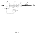
- the polarization of the light inputted to PC 10 is adjusted to a suitable one for the input to the waveguide 14.
- the polarization maintaining fiber 12 maintains the adjusted polarization.
- the PBS 11 in the middle of the polarization maintaining fiber splits orthogonal polarizations one of which is passed through to PC 15 and the other of which is dropped to PD 13.
- the PD 13 detects the power of the dropped light and feeds it back to PC 10 for adjustment of the polarization of the input light.
- the through light of PBS 11 is inputted to PC 15 through the polarization maintaining fiber and its polarization is again adjusted precisely to the suitable polarization for the input to the waveguide 14 just before the waveguide 14.
- the waveguide 14 In the waveguide 14, the light is signal-processed and outputted to output port.
- the function of the waveguide 14 is the same as in Fig. 1 .
- an additional PC 15 is needed to make the state of the polarization suitable for the input to waveguide 14, which causes additional cost and complex device configuration.
- the state of the polarization is adjusted to a suitable state for the input to waveguide 14.
- Suitable means that the state of the polarization is made linear and the direction of the linear polarization is matched to one of the principal axes (fast axis or slow axis) of the waveguide 14. Otherwise, the light splits into two lights which have orthogonal polarizations to each other in the waveguide 14 and propagate in different speeds in the waveguide 14. Therefore, after outputted from the waveguide 14, the light signal becomes superposition of two light signals shifted to each other, which causes deterioration of the optical signal. Therefore, when the nonlinear waveguide 14 is used, the direction of polarization of the input light to the waveguide 14 has to be matched to the principal axis of the waveguide 14.
- Polarization maintaining fibers overcome this problem.
- structural stress is intentionally induced during the fabrication process. This structural stress induces a difference in the speed of light for two perpendicular polarizations traveling through the fiber.
- This birefringence creates two principal axes within the fiber, known respectively as the fast and slow axes of the fiber.
- the input light into a PM fiber is linearly polarized and orientated along one of these two axes, then the output from the fiber will remain linearly polarized and aligned with that axis, even when subjected to external stresses.
- a PM waveguide is characterized by principal axes of polarizations; if linearly polarized light is coupled into one of the two principal axes in a PM waveguide, then the output light from the waveguide will remain linearly polarized and aligned with that axis.
- the orientation of the principal axes is wavelength independent.
- patent document 1 describes an optical source comprising polarization control output means.
- the polarization control output means receives a plurality of lights, makes the plurality of lights polarized in the same direction, and keeps the polarization-controlled lights in array.
- the object of the present invention is to provide a control apparatus for adjusting the input polarization to polarization-maintaining waveguide components, in particular, to highly nonlinear polarization-maintaining waveguide components.
- a control apparatus for an adaptive adjustment of the input polarization to a polarization-maintaining waveguide component comprising: a polarization control unit controlling a polarization state of an input light to the polarization-maintaining waveguide component according to an input signal fed back from an output side of the polarization-maintaining waveguide component so that a polarization of an input light to the polarization maintaining waveguide component matches to a principal axis of polarization of the polarization maintaining waveguide component; and a polarization monitor unit monitoring the polarization state at an output of the polarization-maintaining waveguide component and feeding back a monitoring result to the polarization control unit as the input signal.
- the polarization monitor unit is provided at the output of the polarization maintaining waveguide component and the light from the output is monitored of its polarization. Then, the signal of the monitored result is provided to the polarization control unit.
- the present invention simplifies alignment of the components and reduces cost for aligning the components.
- the apparatus for controlling input polarization to the nonlinear waveguide components is configured such that all the light is coupled into a principal axis of polarization avoiding the need for polarization maintaining components or additional PCs between the adaptively adjustable Q/B/Q-PC and the waveguide component monitoring the light at the output of the PM-waveguide
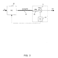
- Fig. 3 shows the first embodiment of the present invention.
- a first embodiment employs a PBS 11 after the birefringent optical waveguide 14 (hereinafter this is expressed by waveguide 14 and means as described in the background paragraph).
- the PBS 11 is either directly attached to the waveguide 14 or connected to it by means of a polarization maintaining fiber 12.
- the PBS 11 is aligned to the waveguide 14 such that the light of the desired principal axis of propagation of the waveguide 14 couples to the through-port of the PBS 11.
- the light outputted from the drop-port is monitored a photodiode PD 13.
- the input polarization is adjusted. This means that the polarization component which matches to the desired principal axis is made maximum and another polarization component is made 0. Therefore, the light adjusted as above is prepared in the state that only the desired polarization is included.
- Fig. 4 and 5 shows the second and third embodiment of the present invention.
- a tunable wavelength filter 16 ( Fig. 4 ) or a wavelength demultiplexer 18 ( Fig. 5 ) can be used in the monitoring branch of the PBS 11 in order to allow for wavelength selective alignment of the polarization axes.
- the advantage of placing the PBS 11 after the waveguide 14 is that the wavelength multiplexer 15 before the waveguide 14 has not to be polarization maintaining, thus reducing the overall required alignment steps of polarization axis of polarization maintaining components.
- polarization controllers 10-1 and 10-2 are provided for each wavelength.
- the embodiment is not restricted to multiplexing only two wavelengths and can have arbitrary number of wavelengths. If more than two wavelengths are provided, the corresponding number of PCs are also provided for each wavelength.
- the polarizations of light of each wavelength are adjusted independently to each other for a suitable state to be inputted to the waveguide 14.
- Each light from PCs 10-1 and 10-2 is coupled by coupler 15 and is inputted to the waveguide 14.
- a polarization maintaining fiber 12 is attached to the output of the waveguide 14.
- the light propagated through the waveguide 14 is inputted to PBS 11 via PI-fiber 12.
- PBS 11 one of polarizations orthogonal to each other is dropped to the tunable wavelength filter 16 for each wavelength.
- the tunable wavelength filter 16 selects one of two wavelengths and the light of the selected wavelength is inputted to PD 13.
- the PD 13 detects the power of the light and feeds it back to PC 10-1 or 10-2 depending on the wavelength selected. Changing the wavelength that the tunable wavelength filter 16 selects allows for adjusting the polarization for each wavelength.
- Fig. 5 the tunable wavelength filter 16 in Fig. 4 is replaced by the wavelength demultiplexer 18.
- the wavelength demultiplexer 18 By using two PDs 19-1 and 19-2, both wavelengths are monitored simultaneously, thereby eliminating the process of changing the wavelength to be monitored.
- the operation of the other components is the same as Fig. 4 . Therefore, the explanation of that is omitted.
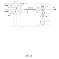
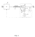
- Fig. 6 shows the fourth embodiment of the present invention.
- Another type of preferred configuration combines the control apparatus for adjusting the input polarization to polarization-maintaining waveguide components 14 with the functionality of power monitoring.
- a portion of the output light of the waveguide 14 is coupled to a polarizer 22 by means of a polarization maintaining optical power divider 20.
- the optical power divider 20 is either directly attached to the waveguide 14 or connected to it by means of a polarization maintaining fiber 12.
- the polarizer 22 is either directly attached to or integrated with the optical power divider 20, or connected to it by means of a polarization maintaining fiber 21.
- the waveguide 14, the optical power divider 20, and the polarizer 22 have to be aligned with each other such that their principal axes are all parallel.
- the through-axis of the polarizer 22 is aligned to the desired principal axis of polarization of the waveguide 14.
- a photodiode 13-1 is attached to the output port of the polarizer 22 allowing detection of the optical power in the desired linear polarization state.
- the input polarization is adjusted such that the photodiode signal is maximized. Since the loss between waveguide input and photodiode is well known, the photodiode signal can be used for power monitoring.
- a polarization filter or PBS can be used as polarizer 22.
- PD 13-2 is not provided.
- the polarization filter passes only one polarization and the light with the polarization is detected by PD 13-1.
- the other operations are the same as described before.
- both ports of PBS 22 are connected to PDs 13-1 and 13-2 respectively.
- power divider 20 divides input light into two lights which include both polarizations, the lights with each polarization are detected by PDs 13-1 and 13-2 respectively.
- detection signals of either PD 13-1 or PD 13-2 can be used to feed back to PC 10.
- both polarizations are detected by PD 13-1 and 13-2 in the case of PBS, total light is detected which propagates the waveguide 14. Then, it is enabled to determine whether or not the optical signal to propagate in the waveguide 14 exists, thereby enabling to monitor the existence or disappearance of the optical signal, which is needed for system monitoring.
- the polarization independent coupler is usable. See, " Optical fiber telecommunication IIIB" by I. P. Kaminov and T. L. Koch, Academic press, 1997, Chapter8, IX. B. pages 362-363 .
- Fig. 7 shows the fifth embodiment of the present invention.
- a non-PM tunable polarization maintaining tunable wavelength filter can be added after the polarizer in order to allow for wavelength selective alignment and monitoring.
- a plurality of wavelengths is used.
- the power divider 20 is attached directly to the waveguide 14 or connected to the waveguide 14 via a polarization maintaining fiber 12.
- the power divider 20 is attached to or integrated with the polarizer 22 or connected to it via a polarization maintaining fiber 21.
- the power divider 20 itself is a polarization independent device.
- the power divider 20 divides the light and dropped light is inputted to polarizer.
- the polarizer can be a polarization filter or PBS.
- a switch 25 is not provided because the polarization filter passes only one polarization.
- the polarization for each wavelength is adjusted.
- both polarizations which are orthogonal to each other are outputted from each port.
- Each port is connected to switch 25.
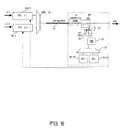
- Fig. 8 shows the sixth embodiment of the present invention.
- the power divider 20 is attached directly to the waveguide 14 or connected to it via a polarization maintaining fiber 12.
- the power divider 20 itself is a polarization independent device.
- the power divider 20 is connected to or integrated with a tunable wavelength filter 16a.
- the tunable wavelength filter 16a is connected to polarizer 22.
- the connecting optical fiber from the power divider 20 to the polarizer 22 is a polarization maintaining one 30.
- the tunable wavelength filter 16a is a polarization independent filter.
- Fig. 9 shows the seventh embodiment of the present invention.
- Another option is to use a non-PM wavelength demultiplexer after the polarizer with two or more ports.
- the lights demultiplexed by the wavelength demultiplexer 18 are detected by PDs 19-1 and 19-2 respectively.
- the tunable wavelength filter 16 is replaced by the wavelength demultiplexer 18 compared to Fig. 7 . This configuration enables for adjusting polarizations for multiple wavelengths simultaneously.
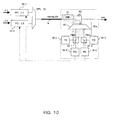
- Fig. 10 shows the eighth embodiment of the present invention.
- the wavelength selection means after the polarizer/PBS, it may be placed before it.
- the tunable wavelength filter 16a is replaced by the wavelength demultiplexer 18 compared to Fig. 8 .
- Connections (12, 30a) between the waveguide 14 and the power divider 20, the power divider 20 and the wavelength demultiplexer 18, and the wavelength demultiplexer 18 and PBSs should be polarization maintaining ones, and the power divider 20 and the wavelength demuliplexer 18 are preferably polarization independent ones.
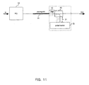
- Figs 11 and 12 show the ninth and tenth embodiments of the present invention.
- Yet another configuration employs an optical power divider 20 after the waveguide 14 and a polarimeter 35 for monitoring the state of polarization.
- the optical power divider 20 is either directly attached to the waveguide 14 or connected to it by means of a polarization maintaining fiber 12.
- the polarimeter 35 is either directly attached to or integrated with the optical power divider 20, or connected to it by means of a polarization maintaining fiber 21 and 30.
- the power divider 20 and the tunable wavelength filter 16a are preferably polarization independent ones. Based on the measured state of polarization the input polarization is adjusted such that the output polarization is linearized.
- a polarization independent tunable wavelength filter 16a can be used in the monitoring branch of the optical power divider 20 in order to allow for wavelength selective alignment and monitoring.
- the tunable wavelength filter 16a is either directly attached to the power divider 20 or connected to it by means of a polarization maintaining fiber 30.
- the polarimeter 35 connected to the tunable wavelength filter 16a by means of a polarization maintaining fiber 30.
- Another configuration is based on the same concept but with the optical power divider placed at the input port of the waveguide, which has the drawback that it reduces the optical input power.
- Figs. 13 and 14 show the eleventh and twelfth embodiments of the present invention.
- the shape of the output spectrum depends on how precisely a single or two wavelengths are coupled into the desired principal axis of polarization of the waveguide 14.
- monitoring the optical spectrum allows optimizing the input polarization.
- a non-PM or polarization independent optical power divider 20 at the output of the waveguide 14 splits a part of the light to an optical spectrum analyzer 40 for monitoring the optical spectrum.
- the input polarization is adjusted such that the shape of the spectrum is optimized in the desired way (e.g. flat high power output in the case of supercontinuum generation), which correlates to the coupling into a principal axis of polarization with the desired chromatic dispersion characteristic.
- a non-PM or polarization independent optical power divider 20 at the output of the waveguide 14 splits a part of the light to an optical filter 16 for monitoring the power of the desired spectral component.
- the optical power of the spectral component is used as feedback signal for adjusting the input polarization.
- the optical filter 16 can be an optical tunable wavelength filter which can change the pass wavelength.
- Figs. 15 and 16 show the thirteenth and fourteenth embodiments of the present invention.
- Fig. 15 corresponds to Fig. 13
- Fig. 16 corresponds to Fig. 14 .
- PC 10-1 and 10-2 control polarizations of lights of each wavelength.
- the output lights are coupled by coupler 15 and outputted to waveguide 14.
- light is inputted to the power divider 20.
- the power divider 20 splits the light to the optical spectrum analyzer 40.
- the optical spectrum analyzer analyzes the spectrum of the light and sends back the signal obtained from the analysis to each PC 10-1 and 10-2.
- Each PC 10-1 and 10-2 adjusts polarization of each wavelength to an optimized one.
- the wavelength filter 16 and photodiode 13 are provided in place of the optical spectrum analyzer 40.
- the wavelength filter 16 selects and passes a specific wavelength to PD 13.
- PD 13 detects the power of the light of the selected wavelength. The result of the detection is fed back to PCs 10-1 and 10-2 and used to control polarization of each wavelength.
- the number of the wavelengths is not limited to 2, but can be an arbitrary number.
- control apparatus may have the following configuration:
Abstract
Description
- This invention relates to the control apparatus for controlling the polarization of light inputted to polarization-maintaining (PM) waveguide components, in particular, to highly nonlinear polarization-maintaining waveguide components.
- Many waveguide components used in optical transmission systems have polarization-dependent, more specifically polarization maintaining, characteristics and thus require the coupling of the input light into a principal axis of polarization. Among these polarization-maintaining components are nonlinear optical waveguides, such as small-effective area microstructured fibers and semiconductor-based components utilizing sub-band transitions, which enable all-optical signal processing at ultra-high speeds, e.g., wavelength conversion, all-optical 2R and 3R regeneration, and supercontinuum generation.
- The capability of coupling the optical power into one of the two principal axes of polarization-maintaining components in a precisely controllable way becomes of utmost importance. In the case of a static linear input polarization (e.g., light originating from a laser source) it is sufficient to directly connect the source and the waveguide device (e.g. , a modulator) with a polarization maintaining fiber (PMF) aligned such that the linear polarization is maintained and coupled into the desired principal axis of polarization of the waveguide. In the case the input polarization is static but with a nonlinear state of polarization (any state of polarization except a linear one, e.g., elliptic polarization, circular polarization), a polarization controller (PC) is used to transfer the state of polarization of the light source into a linear polarization at the input of the waveguide. One way is to use a Q(uarter)/H(alf)/Q(uarter) lambda polarization controller comprising a λ/4-, a λ/2-, and a λ/4-waveplate, with adjustable relative orientation of their principal axes of polarization, which allows the transformation of an arbitrary state of polarization into another arbitrary state of polarization, has to be adjusted such that the polarization of the light becomes linear at the PM-waveguide input. If properly aligned PM-components are used between PC and PM-waveguide it is sufficient to use a Q/H lambda PC. The λ/4-waveplate allows transforming an arbitrary elliptic polarization into a linear polarization and the λ/2-waveplate allows rotating this linear polarization state to an arbitrary angle.
- At points of an optical fiber transmission line other than the laser source, the state of polarization usually changes over time because of a change of temperature or stress on the optical fiber. One way to deal with such a non-static state of the input polarization to a waveguide component which has polarization-dependent characteristics is to apply a polarization diversity scheme. In such a scheme, the two polarization components are separated by a polarization beam splitter (PBS) and treated independently such that the device characteristics become virtually polarization-independent. However, this scheme usually is not suitable for all-optical signal processing applications, which employ nonlinear effects proportional to the signal power, because it is uncertain how the signal power is distributed between the two principal axes of polarizations and because nonlinear effects are proportional to the input power.
- A second way that is also compatible with all-optical signal processing applications is the adaptive adjustment of the input polarization by means of a polarization controller before the PM-waveguide such that all the signal light is coupled into one principal axis of the PM-waveguide. A commonly used approach is to place a PBS after the Q/H PC. One port is used to supply a linear input polarization to the PM-waveguide component and the other port is used for monitoring purposes. By minimizing the signal power coupled into the polarization state used for monitoring, the PCs can adaptively adjust the polarization of input light such that all the power passes through the PBS. In order to couple the thus obtained linear polarization at the output of the PBS into a principal axis of the waveguide (PM-waveguide), the two components have to be connected by PM-components. Another option is to use non-PM components. Assuming that the polarization transfer function of these components does not change over time, a static H/Q PC can be used after the PBS.
-
Fig. 1 andFig. 2 show conventional control apparatus of polarization. - In
Fig. 1 , one example of conventional polarization control apparatus is shown. The light with arbitrary polarization is inputted to PC 10. The polarization of the inputted light is adjusted by PC 10 and the adjusted light is inputted to apolarization maintaining fiber 12 and propagates in thepolarization maintaining fiber 12 to be inputted toPBS 11. By PBS 11, a part of the adjusted light with one polarization is sent through and the other part of the adjusted light with another polarization orthogonal to the one polarization is dropped toPD 13. ThePD 13 detects the power of the dropped light and feeds it back to PC 10 to minimize the power of the dropped light by changing the state of polarization of the input light to PC 10. - The light which passes through PBS 11 is inputted to a
polarization maintaining fiber 12 and sent towaveguide 14. Here, thewaveguide 14 is an optically nonlinear medium used for an optical switch, a 3R regenerator, a wavelength converter or the like. The light inputted to thewaveguide 14 is signal-processed without being converted to an electrical signal. In the case ofFig. 1 , an additionalpolarization maintaining fiber 12 is provided betweenPBS 11 andwaveguide 14, because adjusted state of polarization needs to be kept to the input of thewaveguide 14, which causes costly difficult alignment of the components and is the problem. - In
Fig. 2 , the polarization of the light inputted to PC 10 is adjusted to a suitable one for the input to thewaveguide 14. Thepolarization maintaining fiber 12 maintains the adjusted polarization. ThePBS 11 in the middle of the polarization maintaining fiber splits orthogonal polarizations one of which is passed through to PC 15 and the other of which is dropped toPD 13. ThePD 13 detects the power of the dropped light and feeds it back to PC 10 for adjustment of the polarization of the input light. The through light ofPBS 11 is inputted to PC 15 through the polarization maintaining fiber and its polarization is again adjusted precisely to the suitable polarization for the input to thewaveguide 14 just before thewaveguide 14. In thewaveguide 14, the light is signal-processed and outputted to output port. InFig. 2 , the function of thewaveguide 14 is the same as inFig. 1 . In this case, an additional PC 15 is needed to make the state of the polarization suitable for the input towaveguide 14, which causes additional cost and complex device configuration. - In the above configuration, the state of the polarization is adjusted to a suitable state for the input to
waveguide 14. "Suitable" means that the state of the polarization is made linear and the direction of the linear polarization is matched to one of the principal axes (fast axis or slow axis) of thewaveguide 14. Otherwise, the light splits into two lights which have orthogonal polarizations to each other in thewaveguide 14 and propagate in different speeds in thewaveguide 14. Therefore, after outputted from thewaveguide 14, the light signal becomes superposition of two light signals shifted to each other, which causes deterioration of the optical signal. Therefore, when thenonlinear waveguide 14 is used, the direction of polarization of the input light to thewaveguide 14 has to be matched to the principal axis of thewaveguide 14. - The act of "polarization, maintaining" (PM) is explained below.
- When a conventional single mode fiber is bent or twisted, stresses are induced in the fiber. These stresses will change the polarization state of light traveling through the fiber. If the fiber is subjected to any changes in position or temperature, then the final output polarization will vary with time. This means that a linear state of polarization cannot be reliably maintained until the output of the fiber even in short lengths of fiber.
- Polarization maintaining fibers (PM fibers) overcome this problem. In these fibers structural stress is intentionally induced during the fabrication process. This structural stress induces a difference in the speed of light for two perpendicular polarizations traveling through the fiber. This birefringence creates two principal axes within the fiber, known respectively as the fast and slow axes of the fiber. Provided the input light into a PM fiber is linearly polarized and orientated along one of these two axes, then the output from the fiber will remain linearly polarized and aligned with that axis, even when subjected to external stresses.
- This also can be used for PM-waveguides other than fibers: a PM waveguide is characterized by principal axes of polarizations; if linearly polarized light is coupled into one of the two principal axes in a PM waveguide, then the output light from the waveguide will remain linearly polarized and aligned with that axis. The orientation of the principal axes is wavelength independent.
- As a prior art,
patent document 1 describes an optical source comprising polarization control output means. The polarization control output means receives a plurality of lights, makes the plurality of lights polarized in the same direction, and keeps the polarization-controlled lights in array.
[patent document 1]
Japanese Patent Application Publication No.2001-356378 - The object of the present invention is to provide a control apparatus for adjusting the input polarization to polarization-maintaining waveguide components, in particular, to highly nonlinear polarization-maintaining waveguide components.
- The above object is achieved by providing a control apparatus for an adaptive adjustment of the input polarization to a polarization-maintaining waveguide component, comprising: a polarization control unit controlling a polarization state of an input light to the polarization-maintaining waveguide component according to an input signal fed back from an output side of the polarization-maintaining waveguide component so that a polarization of an input light to the polarization maintaining waveguide component matches to a principal axis of polarization of the polarization maintaining waveguide component; and a polarization monitor unit monitoring the polarization state at an output of the polarization-maintaining waveguide component and feeding back a monitoring result to the polarization control unit as the input signal.
- According to the present invention, the polarization monitor unit is provided at the output of the polarization maintaining waveguide component and the light from the output is monitored of its polarization. Then, the signal of the monitored result is provided to the polarization control unit.
- By placing the polarization monitor unit at the output of the polarization maintaining waveguide component, additional PC or additional polarization maintaining fiber is no longer needed. Then, the present invention simplifies alignment of the components and reduces cost for aligning the components.
-
-
Fig. 1 andFig. 2 show conventional control apparatus of polarization. -
Fig. 3 shows the first embodiment of the present invention. -
Fig. 4 and5 shows the second and third embodiment of the present invention. -
Fig. 6 shows the fourth embodiment of the present invention. -
Fig. 7 shows the fifth embodiment of the present invention. -
Fig. 8 shows the sixth embodiment of the present invention. -
Fig. 9 shows the seventh embodiment of the present invention. -
Fig. 10 shows the eighth embodiment of the present invention. -
Figs 11 and12 show the ninth and tenth embodiments of the present invention. -
Figs. 13 and14 show the eleventh and twelfth embodiments of the present invention. -
Figs. 15 and16 show the thirteenth and fourteenth embodiments of the present invention. - The embodiments of the present invention are described in reference to the attached drawings in which like numbers are attached to the like components
- In the embodiment of the present invention, the apparatus for controlling input polarization to the nonlinear waveguide components is configured such that all the light is coupled into a principal axis of polarization avoiding the need for polarization maintaining components or additional PCs between the adaptively adjustable Q/B/Q-PC and the waveguide component monitoring the light at the output of the PM-waveguide
-
Fig. 3 shows the first embodiment of the present invention. - A first embodiment employs a
PBS 11 after the birefringent optical waveguide 14 (hereinafter this is expressed bywaveguide 14 and means as described in the background paragraph). ThePBS 11 is either directly attached to thewaveguide 14 or connected to it by means of apolarization maintaining fiber 12. ThePBS 11 is aligned to thewaveguide 14 such that the light of the desired principal axis of propagation of thewaveguide 14 couples to the through-port of thePBS 11. The light outputted from the drop-port is monitored aphotodiode PD 13. By minimizing the optical power of light which is outputted from drop-port ofPBS 11 and has different polarization from the one matching to the desired principal axis of thewaveguide 14, the input polarization is adjusted. This means that the polarization component which matches to the desired principal axis is made maximum and another polarization component is made 0. Therefore, the light adjusted as above is prepared in the state that only the desired polarization is included. -
Fig. 4 and5 shows the second and third embodiment of the present invention. - For applications in which two or more wavelengths have to be coupled into the
waveguide 14, a tunable wavelength filter 16 (Fig. 4 ) or a wavelength demultiplexer 18 (Fig. 5 ) can be used in the monitoring branch of thePBS 11 in order to allow for wavelength selective alignment of the polarization axes. For this kind of application the advantage of placing thePBS 11 after thewaveguide 14 is that thewavelength multiplexer 15 before thewaveguide 14 has not to be polarization maintaining, thus reducing the overall required alignment steps of polarization axis of polarization maintaining components. - In
Fig. 4 , polarization controllers 10-1 and 10-2 are provided for each wavelength. In the figure, although only two wavelengths are shown, but the embodiment is not restricted to multiplexing only two wavelengths and can have arbitrary number of wavelengths. If more than two wavelengths are provided, the corresponding number of PCs are also provided for each wavelength. - At PCs 10-1 and 10-2, the polarizations of light of each wavelength are adjusted independently to each other for a suitable state to be inputted to the
waveguide 14. Each light from PCs 10-1 and 10-2 is coupled bycoupler 15 and is inputted to thewaveguide 14. Apolarization maintaining fiber 12 is attached to the output of thewaveguide 14. The light propagated through thewaveguide 14 is inputted toPBS 11 via PI-fiber 12. At thePBS 11, one of polarizations orthogonal to each other is dropped to thetunable wavelength filter 16 for each wavelength. Thetunable wavelength filter 16 selects one of two wavelengths and the light of the selected wavelength is inputted toPD 13. ThePD 13 detects the power of the light and feeds it back to PC 10-1 or 10-2 depending on the wavelength selected. Changing the wavelength that thetunable wavelength filter 16 selects allows for adjusting the polarization for each wavelength. - In
Fig. 5 , thetunable wavelength filter 16 inFig. 4 is replaced by thewavelength demultiplexer 18. By using two PDs 19-1 and 19-2, both wavelengths are monitored simultaneously, thereby eliminating the process of changing the wavelength to be monitored. The operation of the other components is the same asFig. 4 . Therefore, the explanation of that is omitted. -
Fig. 6 shows the fourth embodiment of the present invention. - Another type of preferred configuration combines the control apparatus for adjusting the input polarization to polarization-maintaining
waveguide components 14 with the functionality of power monitoring. A portion of the output light of thewaveguide 14 is coupled to apolarizer 22 by means of a polarization maintainingoptical power divider 20. Theoptical power divider 20 is either directly attached to thewaveguide 14 or connected to it by means of apolarization maintaining fiber 12. Thepolarizer 22 is either directly attached to or integrated with theoptical power divider 20, or connected to it by means of apolarization maintaining fiber 21. Thewaveguide 14, theoptical power divider 20, and thepolarizer 22 have to be aligned with each other such that their principal axes are all parallel. The through-axis of thepolarizer 22 is aligned to the desired principal axis of polarization of thewaveguide 14. A photodiode 13-1 is attached to the output port of thepolarizer 22 allowing detection of the optical power in the desired linear polarization state. The input polarization is adjusted such that the photodiode signal is maximized. Since the loss between waveguide input and photodiode is well known, the photodiode signal can be used for power monitoring. - In
Fig. 6 , a polarization filter or PBS can be used aspolarizer 22. When the polarization filter is used, PD 13-2 is not provided. The polarization filter passes only one polarization and the light with the polarization is detected by PD 13-1. The other operations are the same as described before. - When PBS is used, both ports of
PBS 22 are connected to PDs 13-1 and 13-2 respectively. Aspower divider 20 divides input light into two lights which include both polarizations, the lights with each polarization are detected by PDs 13-1 and 13-2 respectively. In this case, detection signals of either PD 13-1 or PD 13-2 can be used to feed back toPC 10. As both polarizations are detected by PD 13-1 and 13-2 in the case of PBS, total light is detected which propagates thewaveguide 14. Then, it is enabled to determine whether or not the optical signal to propagate in thewaveguide 14 exists, thereby enabling to monitor the existence or disappearance of the optical signal, which is needed for system monitoring. - For the
power divider 20, the polarization independent coupler is usable. See, "Optical fiber telecommunication IIIB" by I. P. Kaminov and T. L. Koch, Academic press, 1997, Chapter8, IX. B. pages 362-363. -
Fig. 7 shows the fifth embodiment of the present invention. - In addition, a non-PM tunable polarization maintaining tunable wavelength filter can be added after the polarizer in order to allow for wavelength selective alignment and monitoring. In
Fig. 7 , a plurality of wavelengths is used. Thepower divider 20 is attached directly to thewaveguide 14 or connected to thewaveguide 14 via apolarization maintaining fiber 12. And thepower divider 20 is attached to or integrated with thepolarizer 22 or connected to it via apolarization maintaining fiber 21. Further, thepower divider 20 itself is a polarization independent device. Thepower divider 20 divides the light and dropped light is inputted to polarizer. The polarizer can be a polarization filter or PBS. In the case of a polarization filter, aswitch 25 is not provided because the polarization filter passes only one polarization. By selecting the wavelength of the light by thetunable wavelength filter 16, the polarization for each wavelength is adjusted. In the case of PBS, both polarizations which are orthogonal to each other are outputted from each port. Each port is connected to switch 25. By switching the path by theswitch 25, light of both polarizations can be monitored, enabling to monitor the existence or disappearance of the optical signal. -
Fig. 8 shows the sixth embodiment of the present invention. - Alternatively to placing the wavelength selection means after the polarizer/PBS, it may be placed before it. In
Fig. 8 , thepower divider 20 is attached directly to thewaveguide 14 or connected to it via apolarization maintaining fiber 12. Thepower divider 20 itself is a polarization independent device. Thepower divider 20 is connected to or integrated with atunable wavelength filter 16a. And thetunable wavelength filter 16a is connected topolarizer 22. The connecting optical fiber from thepower divider 20 to thepolarizer 22 is a polarization maintaining one 30. But thetunable wavelength filter 16a is a polarization independent filter. - For a polarization independent tunable wavelength filter, see
- "Polarization independent, linear-tuned interference filter with constant transmission characteristics over 1530-1570-nm tuning range" Mekada, N.; Al-Hamdan, A; Chong, T. H.; Daut, D. G.; Photonics Technology Letters, IEEE, Volume 9, Issue 6, June 1997, pages 782-784.
-
Fig. 9 shows the seventh embodiment of the present invention. - Another option is to use a non-PM wavelength demultiplexer after the polarizer with two or more ports. The lights demultiplexed by the
wavelength demultiplexer 18 are detected by PDs 19-1 and 19-2 respectively. InFig. 9 , thetunable wavelength filter 16 is replaced by thewavelength demultiplexer 18 compared toFig. 7 . This configuration enables for adjusting polarizations for multiple wavelengths simultaneously. - These configurations can be modified in such a way that instead of a polarizer a polarization beam splitter is used. By using an optical switch before the wavelength selection means, the two polarization axes of the PBS can be monitored alternatively.
-
Fig. 10 shows the eighth embodiment of the present invention. - Alternatively to placing the wavelength selection means after the polarizer/PBS, it may be placed before it. In
Fig. 10 , thetunable wavelength filter 16a is replaced by thewavelength demultiplexer 18 compared toFig. 8 . Connections (12, 30a) between thewaveguide 14 and thepower divider 20, thepower divider 20 and thewavelength demultiplexer 18, and thewavelength demultiplexer 18 and PBSs should be polarization maintaining ones, and thepower divider 20 and thewavelength demuliplexer 18 are preferably polarization independent ones. - For a polarization independent wavelength demultiplexer, see "Extremely small polarization independent phased-array demultiplexers on InP", Bissessur, H.; Pagnod-Rossiaux, P.; Mestric, R.; Martin, B.; Photonics Technology Letters, IEEE, Volume 8, Issue 4, April 1996, pages 554-556.
- Other configurations can be based on the same concept but with the optical power divider(s) placed at the input port(s) of the
waveguide 14, which has the drawback that it reduces the optical input power. -
Figs 11 and12 show the ninth and tenth embodiments of the present invention. - Yet another configuration employs an
optical power divider 20 after thewaveguide 14 and apolarimeter 35 for monitoring the state of polarization. Theoptical power divider 20 is either directly attached to thewaveguide 14 or connected to it by means of apolarization maintaining fiber 12. Thepolarimeter 35 is either directly attached to or integrated with theoptical power divider 20, or connected to it by means of apolarization maintaining fiber power divider 20 and thetunable wavelength filter 16a are preferably polarization independent ones. Based on the measured state of polarization the input polarization is adjusted such that the output polarization is linearized. - In addition, a polarization independent
tunable wavelength filter 16a can be used in the monitoring branch of theoptical power divider 20 in order to allow for wavelength selective alignment and monitoring. Thetunable wavelength filter 16a is either directly attached to thepower divider 20 or connected to it by means of apolarization maintaining fiber 30. Thepolarimeter 35 connected to thetunable wavelength filter 16a by means of apolarization maintaining fiber 30. - Another configuration is based on the same concept but with the optical power divider placed at the input port of the waveguide, which has the drawback that it reduces the optical input power.
-
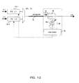
Figs. 13 and14 show the eleventh and twelfth embodiments of the present invention. - In the case of birefringent waveguide used for all-optical signal processing, the shape of the output spectrum depends on how precisely a single or two wavelengths are coupled into the desired principal axis of polarization of the
waveguide 14. Thus, monitoring the optical spectrum allows optimizing the input polarization. A non-PM or polarization independentoptical power divider 20 at the output of thewaveguide 14 splits a part of the light to anoptical spectrum analyzer 40 for monitoring the optical spectrum. The input polarization is adjusted such that the shape of the spectrum is optimized in the desired way (e.g. flat high power output in the case of supercontinuum generation), which correlates to the coupling into a principal axis of polarization with the desired chromatic dispersion characteristic. - For certain nonlinear signal applications (e.g. four wave mixing, cross-phase modulation (XPM), supercontinuum generation), it is sufficient to monitor only the optical power in a certain part of the optical spectrum. A non-PM or polarization independent
optical power divider 20 at the output of thewaveguide 14 splits a part of the light to anoptical filter 16 for monitoring the power of the desired spectral component. The optical power of the spectral component is used as feedback signal for adjusting the input polarization. Theoptical filter 16 can be an optical tunable wavelength filter which can change the pass wavelength. -
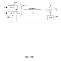
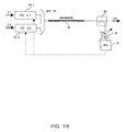
Figs. 15 and16 show the thirteenth and fourteenth embodiments of the present invention. - These embodiments are modifications of the embodiments of
Figs. 13 and14 in order to accommodate multiple wavelength cases.Fig. 15 corresponds toFig. 13 andFig. 16 corresponds toFig. 14 . - In
Fig. 15 , PC 10-1 and 10-2 control polarizations of lights of each wavelength. The output lights are coupled bycoupler 15 and outputted towaveguide 14. After propagation along thewaveguide 14, light is inputted to thepower divider 20. Thepower divider 20 splits the light to theoptical spectrum analyzer 40. The optical spectrum analyzer analyzes the spectrum of the light and sends back the signal obtained from the analysis to each PC 10-1 and 10-2. Each PC 10-1 and 10-2 adjusts polarization of each wavelength to an optimized one. - In
Fig. 16 , thewavelength filter 16 andphotodiode 13 are provided in place of theoptical spectrum analyzer 40. Thewavelength filter 16 selects and passes a specific wavelength toPD 13.PD 13 detects the power of the light of the selected wavelength. The result of the detection is fed back to PCs 10-1 and 10-2 and used to control polarization of each wavelength. Of course, the number of the wavelengths is not limited to 2, but can be an arbitrary number. - According to another example the control apparatus may have the following configuration:
- 1) A control apparatus for an adaptive adjustment of the input polarization to a polarization-maintaining waveguide component, comprising: a polarization control unit controlling a polarization state of an input light to the polarization-maintaining waveguide component according to an input signal fed back from an output side of the polarization-maintaining waveguide component so that a polarization of an input light to the polarization maintaining waveguide component matches to a principal axis of polarization of the polarization maintaining waveguide component; a polarization monitor unit monitoring the polarization state at an output of the polarization-maintaining waveguide component and feeding back a monitoring result to the polarization control unit as the input signal.
- 2) The control apparatus according to 1), wherein the polarization monitor unit further monitors an existence or disappearance of an optical signal traveling through the polarization-maintaining waveguide component.
- 3) The control apparatus according to 1), wherein the polarization monitor unit comprises a polarization beam splitter, the polarization beam splitter is aligned to the polarization-maintaining waveguide component so that the light with the polarization state which matches to the principal axis of the polarization-maintaining waveguide component couples to the trough-port of the polarization beam splitter and a light of a drop-port is used for polarization state monitoring.
- 4) The control apparatus according to 3), wherein a plurality of the polarization control units are provided for an equal number of wavelengths included in the input light, a tunable wavelength filter is provided after the polarization beam splitter along a feedback path, and each of the plurality of the polarization control units controls a polarization state of the input light for each wavelength based on a feedback signal obtained by detecting a power of a light passing through the tunable wavelength filter.
- 5) The control apparatus according to 3), wherein a plurality of the polarization control units are provided for an equal number of wavelengths included in the input light, a wavelength demultiplexing unit is provided after the polarization beam splitter along a feedback path and demultiplexing an input light into each wavelength, and each of the plurality of the polarization control units controls a polarization state of the input light for each wavelength based on a feedback signal obtained by detecting each power of lights demultiplexed by the demultiplexing unit.
- 6) The control apparatus according to 2), wherein the polarization monitor unit comprises: an optical power divider placed after the polarization-maintaining waveguide component, a polarization selective unit connected to one port of the optical power divider with its polarization axis aligned to that of a principal axis of polarization of the polarization-maintaining waveguide component, and a monitoring unit connected to the polarization selective unit for optical power detection and providing a feedback signal to the polarization control unit.
- 7) The control apparatus according to 6), wherein the polarization selective unit is a polarizer with its through-axis aligned to a desired principal axis of the polarization maintaining waveguide component, and the monitoring unit is a photodiode connected to an output of the polarizer.
- 8) The control apparatus according to 6), wherein the polarization selective unit is a polarizer with its through-axis aligned to a desired principal axis of the polarization maintaining waveguide component, and the monitoring unit is a tunable wavelength filter connected to an output of the polarizer.
- 9) The control apparatus according to 6), wherein the polarization selective unit is a polarizer with its through-axis aligned to a desired principal axis of the polarization maintaining waveguide component, and the monitoring unit is a wavelength demultiplexer connected to an output of the polarizer.
- 10) The control apparatus according to 6), wherein the polarization selective unit is a polarization beam splitter and the monitoring unit includes two photodiodes connected to two output of the polarization beam splitter.
- 11) The control apparatus according to 6), further comprising an optical switch, wherein the polarization selective unit is a polarization beam splitter and the monitoring unit, the optical switch is connected to output ports of the polarization beam splitter, and the monitoring unit includes a tunable wavelength filter connected to an output of the optical switch.
- 12) The control apparatus according to 6), further comprising an optical switch, wherein the polarization selective unit is a polarization beam splitter and the monitoring unit, the optical switch is connected to output ports of the polarization beam splitter, and the monitoring unit includes a wavelength demultiplexer connected to an output of the optical switch.
- 13) The control apparatus according to 2), wherein the polarization monitor unit comprises an optical power divider placed after the polarization-maintaining waveguide component, a wavelength selective unit connected to one port of the optical power divider, a polarization selective unit connected to the wavelength selective unit with its polarization axis aligned to that of a principal axis of polarization of the polarization-maintaining waveguide component, and a monitoring unit connected to the polarization selective unit for optical power detection and providing a feedback signal to the polarization control unit.
- 14) The control apparatus according to 13), wherein the wavelength selective unit is a tunable wavelength filter and the polarization selective unit is a polarizer.
- 15) The control apparatus according to 13), wherein the wavelength selective unit is a tunable wavelength filter and the polarization selective unit includes a polarization beam splitter and photodiodes connected to the polarization beam splitter.
- 16) The control apparatus according to 13), wherein the wavelength selective unit is a wavelength demultiplexer and the polarization selective unit includes a polarization beam splitter connected to output ports of the wavelength demultiplexer and photodiodes connected to the polarization beam splitter.
- 17) The control apparatus according to 1), wherein the polarization monitor unit comprises: an optical power divider placed after the polarization-maintaining waveguide component, and a polarimeter analyzing the state of polarization and providing a feedback signal to the polarization control unit.
- 18) The control apparatus according to 1), wherein the polarization monitor unit comprises: an optical power divider placed after the polarization-maintaining waveguide component, a tunable wavelength filter connected to one output port of the optical power divider, allowing monitoring one of a plurality of wavelengths, and a polarimeter analyzing the state of polarization and providing a feedback signal to the polarization control unit.
- 19) The control apparatus according to 1), wherein the polarization monitor unit comprises: a power divider unit connected after the polarization maintaining waveguide component, and a spectrum monitor unit connected to one of output ports of the power divider, analyzing spectrum of a received light, and generating feedback signal to the polarization control unit.
- 20) The control apparatus according to 19), wherein the spectrum monitor unit is an optical spectrum analyzer.
- 21) The control apparatus according to 19), wherein the spectrum monitor unit includes a wavelength selective filter and photodiode detecting a power of a light passing through the wavelength selective filter.
- 22) The control apparatus according to any one of 19) through 21), wherein a plurality of the polarization control units is provided for each wavelength and a wavelength multiplexed light is inputted to the polarization maintaining waveguide component.
Claims (17)
- A control apparatus for an adaptive adjustment of the input polarization to a nonlinear polarization-maintaining waveguide component (14), comprising:a polarization control unit (10) for controlling a polarization state of an input light to the nonlinear polarization-maintaining waveguide component (14) according to an input signal fed back from an output side of the nonlinear polarization-maintaining waveguide component (14) so that a changed linearly polarized wave of an input light to the nonlinear polarization-maintaining waveguide component (14) matches to a principal axis of polarization of the nonlinear polarization-maintaining waveguide component (14) for all-optical signal processing at ultra-high speeds; anda polarization monitor unit for monitoring the polarization state at an output of the nonlinear polarization-maintaining waveguide component (14), feeding back a monitoring result to the polarization control unit (10) as the input signal,wherein the polarization monitor unit comprises:an optical power divider (20) placed after the nonlinear polarization-maintaining waveguide component (14),a polarization selective unit connected to one port of the optical power divider (20) with its polarization axis aligned to that of a principal axis of polarization of the nonlinear polarization-maintaining waveguide component (14), anda monitoring unit connected to the polarization selective unit for optical power detection and providing a feedback signal to the polarization control unit (10).
- The control apparatus according to claim 1, whereinthe polarization selective unit is constituted by a polarizer (22) with its through-axis aligned to a desired principal axis of the nonlinear polarization-maintaining waveguide component (21), andthe monitoring unit is constituted by a photodiode (13) connected to an output of the polarizer.
- The control apparatus according to claim 1, whereinthe polarization selective unit is constituted by a polarizer (22) with its through-axis aligned to a desired principal axis of the nonlinear polarization-maintaining waveguide component (21), andthe monitoring unit is constituted by a tuneable wavelength filter (16) connected to an output of the polarizer (22).
- The control apparatus according to claim 1, whereinthe polarization selective unit is constituted by a polarizer (22) with its through-axis aligned to a desired principal axis of the nonlinear polarization-maintaining waveguide component (21), andthe monitoring unit is constituted by a wavelength demultiplexer (18) connected to an output of the polarizer.
- The control apparatus according to claim 1, whereinthe polarization selective unit is constituted by a polarization beam splitter (22) and the monitoring unit including two photodiodes connected to two outputs of the polarization beam splitter (19-1, 19-2).
- The control apparatus according to claim 5, further comprising an optical switch,
whereinthe polarization selective unit is constituted by a polarization beam splitter (22) and the monitoring unit, the optical switch (25) connected to output ports of the polarization beam splitter (22), and the monitoring unit including a tuneable wavelength filter (16) connected to the output of the optical switch (25). - The control apparatus according to claim 5, further comprising an optical switch,
whereinthe polarization selective unit is constituted by a polarization beam splitter (22) and the monitoring unit, the optical switch (25) connected to output ports of the polarization beam splitter (22), and the monitoring unit including a wavelength demultiplexer (18) connected to the output of the optical switch (25). - The control apparatus according to claim 1, whereinthe polarization monitor unit comprises:an optical power divider (20) placed after the nonlinear polarization-maintaining waveguide component (14),a wavelength selective uni t connected to one port of the optical power divider (20),a polarization selective unit connected to the wavelength selective unit with its polarization axis aligned to that of a principal axis of polarization of the nonlinear polarization-maintaining waveguide component (30), anda monitoring unit connected to the polarization selective unit for optical power detection and providing a feedback signal to the polarization control unit (10).
- The control apparatus according to claim 8, whereinthe wavelength selective unit is constituted by a tuneable wavelength filter (16a) and the polarization selective unit (22) is constituted by a polarizer.
- The control apparatus according to claim 8, whereinthe wavelength selective unit is constituted by a tuneable wavelength filter (16a) and the polarization selective unit including a polarization beam splitter (22) and photodiodes (13-1, 13-2) connected to the polarization beam splitter (22).
- The control apparatus according to claim 8, whereinthe wavelength selective unit is constituted by a wavelength demultiplexer (18) and the polarization selective unit including a polarization beam splitter (22) connected to output ports of the wavelength demultiplexer (18) and photodiodes (19-1, 19-2, 19-3, 19-4) connected to the polarization beam splitter (22).
- The control apparatus according to claim 1, whereinthe polarization monitor unit comprises:an optical power divider (20) placed after the nonlinear polarization-maintaining waveguide component (14),and a polarimeter (35) for analyzing the state of polarization and providing a feedback signal to the polarization control unit (10).
- The control apparatus according to claim 1, whereinthe polarization monitor unit comprises:an optical power divider (20) placed after the nonlinear polarization-maintaining waveguide component (14),a tuneable wavelength filter (16a) connected to one output port of the optical power divider (20), for allowing monitoring one of a plurality of wavelengths, anda polarimeter (35) for analyzing the state of polarization and providing a feedback signal to the polarization control unit (10-1, 10-2).
- The control apparatus according to claim 1, whereinthe polarization monitor unit comprises:a power divider unit (20) connected after the nonlinear polarization-maintaining waveguide component, anda spectrum monitor unit connected to one of the output ports of the power divider (20), for analyzing a spectrum of a received light, and generating feedback signal to the polarization control unit (10).
- The control apparatus according to claim 14, whereinthe spectrum monitor unit is constituted by an optical spectrum analyzer (40).
- The control apparatus according to claim 14, whereinthe spectrum monitor unit includes a wavelength selective filter (16) and a photodiode (13) for detecting the power of the light passing through the wavelength selective filter (16).
- The control apparatus according to any one of claims 14 through 16, whereina plurality of the polarization control units is provided for each wavelength and a wavelength multiplexed light is inputted to the nonlinear polarization-maintaining waveguide component (14).
Priority Applications (1)
| Application Number | Priority Date | Filing Date | Title |
|---|---|---|---|
| DE602004023015T DE602004023015D1 (en) | 2004-03-25 | 2004-03-25 | Adaptive polarization adjustment apparatus for controlling the polarization of input light polarization-maintaining waveguide component |
Applications Claiming Priority (2)
| Application Number | Priority Date | Filing Date | Title |
|---|---|---|---|
| PCT/JP2004/004187 WO2005093497A1 (en) | 2004-03-25 | 2004-03-25 | Apparatus for controlling polarization of light imputed to polarization-maintaining waveguide components |
| EP04723310A EP1728118B1 (en) | 2004-03-25 | 2004-03-25 | Apparatus for controlling polarization of light inputted to polarization-maintaining waveguide components |
Related Parent Applications (1)
| Application Number | Title | Priority Date | Filing Date |
|---|---|---|---|
| EP04723310A Division EP1728118B1 (en) | 2004-03-25 | 2004-03-25 | Apparatus for controlling polarization of light inputted to polarization-maintaining waveguide components |
Publications (3)
| Publication Number | Publication Date |
|---|---|
| EP2000847A2 true EP2000847A2 (en) | 2008-12-10 |
| EP2000847A3 EP2000847A3 (en) | 2008-12-24 |
| EP2000847B1 EP2000847B1 (en) | 2009-09-02 |
Family
ID=34957138
Family Applications (2)
| Application Number | Title | Priority Date | Filing Date |
|---|---|---|---|
| EP08162506A Expired - Fee Related EP2000847B1 (en) | 2004-03-25 | 2004-03-25 | Adaptive polarization adjustment apparatus for controlling polarization of light inputted to polarization-maintaining waveguide components |
| EP04723310A Expired - Fee Related EP1728118B1 (en) | 2004-03-25 | 2004-03-25 | Apparatus for controlling polarization of light inputted to polarization-maintaining waveguide components |
Family Applications After (1)
| Application Number | Title | Priority Date | Filing Date |
|---|---|---|---|
| EP04723310A Expired - Fee Related EP1728118B1 (en) | 2004-03-25 | 2004-03-25 | Apparatus for controlling polarization of light inputted to polarization-maintaining waveguide components |
Country Status (5)
| Country | Link |
|---|---|
| US (1) | US7428349B2 (en) |
| EP (2) | EP2000847B1 (en) |
| JP (1) | JP4546959B2 (en) |
| DE (2) | DE602004021510D1 (en) |
| WO (1) | WO2005093497A1 (en) |
Families Citing this family (11)
| Publication number | Priority date | Publication date | Assignee | Title |
|---|---|---|---|---|
| KR101001621B1 (en) * | 2004-12-02 | 2010-12-17 | 삼성전자주식회사 | Apparatus and method for transforming Polarization |
| JP5162889B2 (en) * | 2006-11-30 | 2013-03-13 | 富士通株式会社 | Optical switch, optical waveform measuring device and control method |
| US8073326B2 (en) * | 2006-12-06 | 2011-12-06 | General Photonics Corporation | Optical polarization division multiplexing in optical communication |
| JP4467557B2 (en) * | 2006-12-25 | 2010-05-26 | 富士通株式会社 | Optical switching method and optical switch |
| JP5393288B2 (en) | 2009-06-23 | 2014-01-22 | 富士通テレコムネットワークス株式会社 | Transmission system and tilt correction method for transmission system |
| JP5703907B2 (en) * | 2011-03-31 | 2015-04-22 | ソニー株式会社 | Nonlinear Raman spectroscopy apparatus, nonlinear Raman spectroscopy system, and nonlinear Raman spectroscopy method |
| JP6191758B2 (en) * | 2014-03-07 | 2017-09-06 | 日本電気株式会社 | Optical transmission device, optical communication device, optical communication system, and optical transmission method |
| CN108155553B (en) * | 2018-01-03 | 2020-03-20 | 上海理工大学 | Fine adjustable optical parametric oscillator with fast gain band switching |
| CN111903078B (en) * | 2018-03-20 | 2022-06-07 | 三菱电机株式会社 | Optical signal control device and optical communication system |
| JP2022110728A (en) | 2021-01-19 | 2022-07-29 | 富士通株式会社 | Wavelength converter and optical transmission system |
| CN114866156A (en) * | 2021-02-05 | 2022-08-05 | 富士通株式会社 | Polarization recovery device and method, and optical receiver |
Family Cites Families (13)
| Publication number | Priority date | Publication date | Assignee | Title |
|---|---|---|---|---|
| JP2668399B2 (en) * | 1988-07-14 | 1997-10-27 | 富士通株式会社 | Light output control device |
| JPH0756955B2 (en) * | 1993-03-30 | 1995-06-14 | 日本電気株式会社 | Polarization control method |
| JP3230784B2 (en) * | 1993-11-01 | 2001-11-19 | 日本電信電話株式会社 | Polarization dispersion compensator |
| JP2739813B2 (en) * | 1993-12-20 | 1998-04-15 | 日本電気株式会社 | Polarization dispersion compensation method |
| US6016213A (en) * | 1996-07-08 | 2000-01-18 | Ditech Corporation | Method and apparatus for optical amplifier gain and noise figure measurement |
| US6038357A (en) * | 1998-02-03 | 2000-03-14 | E-Tek Dynamics, Inc | PDM-WDM for fiberoptic communication networks |
| US7209660B1 (en) * | 1999-12-29 | 2007-04-24 | Forster Energy Llc | Optical communications using heterodyne detection |
| JP4514289B2 (en) * | 2000-06-14 | 2010-07-28 | 古河電気工業株式会社 | Light source device |
| JP3824885B2 (en) * | 2001-05-28 | 2006-09-20 | 富士通株式会社 | Polarization corrector and wavelength division multiplexing apparatus using the same |
| US20020191265A1 (en) * | 2001-06-14 | 2002-12-19 | Lagasse Michael | Multi-stage polarization transformer |
| US6768824B2 (en) * | 2002-10-23 | 2004-07-27 | Fitel Usa Corp | Tunable polarizers |
| US6856386B2 (en) * | 2003-03-21 | 2005-02-15 | Thorlabs, Inc. | Single sweep polarization dependent loss measurement |
| US6961129B2 (en) * | 2003-05-15 | 2005-11-01 | Agilent Technologies, Inc. | Active control of two orthogonal polarizations for heterodyne interferometry |
-
2004
- 2004-03-25 DE DE602004021510T patent/DE602004021510D1/en not_active Expired - Lifetime
- 2004-03-25 DE DE602004023015T patent/DE602004023015D1/en not_active Expired - Lifetime
- 2004-03-25 EP EP08162506A patent/EP2000847B1/en not_active Expired - Fee Related
- 2004-03-25 US US10/596,602 patent/US7428349B2/en not_active Expired - Fee Related
- 2004-03-25 EP EP04723310A patent/EP1728118B1/en not_active Expired - Fee Related
- 2004-03-25 JP JP2006520617A patent/JP4546959B2/en not_active Expired - Fee Related
- 2004-03-25 WO PCT/JP2004/004187 patent/WO2005093497A1/en not_active Application Discontinuation
Non-Patent Citations (4)
| Title |
|---|
| BISSESSUR, H. ET AL.: "Extremely small polarization independent phased-array demultiplexers on InP", PHOTONICS TECHNOLOGY LETTERS, IEEE, vol. 8, no. 4, April 1996 (1996-04-01), pages 554 - 556, XP000587021, DOI: doi:10.1109/68.491224 |
| I. P. KAMINOV; T. L. KOCH: "Optical fiber telecommunication IIIB", 1997, ACADEMIC PRESS, pages: 362 - 363 |
| MEKADA, N. ET AL.: "Polarization independent, linear-tuned interference filter with constant transmission characteristics over 1530-1570-nm tuning range", PHOTONICS TECHNOLOGY LETTERS, IEEE, vol. 9, no. 6, June 1997 (1997-06-01), pages 782 - 784, XP000692417, DOI: doi:10.1109/68.584989 |
| PATENT ABSTRACTS OF JAPAN, vol. 0141, no. 69, pages 1032 |
Also Published As
| Publication number | Publication date |
|---|---|
| EP1728118A1 (en) | 2006-12-06 |
| JP4546959B2 (en) | 2010-09-22 |
| DE602004023015D1 (en) | 2009-10-15 |
| WO2005093497A1 (en) | 2005-10-06 |
| EP2000847A3 (en) | 2008-12-24 |
| JP2007531900A (en) | 2007-11-08 |
| EP1728118B1 (en) | 2009-06-10 |
| EP2000847B1 (en) | 2009-09-02 |
| DE602004021510D1 (en) | 2009-07-23 |
| US20070091310A1 (en) | 2007-04-26 |
| US7428349B2 (en) | 2008-09-23 |
Similar Documents
| Publication | Publication Date | Title |
|---|---|---|
| EP0697775B1 (en) | Multiple-channel all-optical TDM-WDM converter and multiple-channel all-optical TDM demultiplexer | |
| US6529307B1 (en) | Selective intensity modulation of channels in a multiplexed optical communication system | |
| EP2000847B1 (en) | Adaptive polarization adjustment apparatus for controlling polarization of light inputted to polarization-maintaining waveguide components | |
| JPH07327012A (en) | Optical communication system | |
| JP2004029722A (en) | Optical wavelength division multiplexer | |
| US6950611B2 (en) | In-line polarization monitoring and control in lightwave communication systems | |
| JP2003508795A (en) | ADM with line in reflection and wavelength-selective optical cross-connect | |
| CA2419304A1 (en) | Optical repolarizing devices | |
| US11831353B2 (en) | Integrated multi-channel photonics transmitter chip having variable power dividers | |
| US20150372782A1 (en) | A novel mode division multiplexing optical link | |
| US6907199B2 (en) | Method for polarization mode dispersion compensation | |
| US6748126B2 (en) | System for polarization mode dispersion compensation | |
| US7120330B2 (en) | Apparatus for forming a WDM signal having orthogonally polarized optical channels | |
| US7616900B2 (en) | Optical signal degradation compensator | |
| US6411413B1 (en) | Method and apparatus for performing dispersion compensation without a change in polarization and a transmitter incorporating same | |
| US20050174919A1 (en) | Optical polarization controller | |
| Madsen et al. | Versatile integrated PMD emulation and compensation elements | |
| EP3420651B1 (en) | Chromatic dispersion compensation | |
| US11838104B2 (en) | Wavelength multiplexing processor | |
| Melati et al. | Integrated all-optical MIMO demultiplexer for 8-channel MDM-WDM transmission | |
| JP2001324627A (en) | Wavelength dispersing element and wavelength dispersion compensation system | |
| KR20090065051A (en) | Apparatus for adjusting dispersion of optical signal | |
| CA2349730A1 (en) | Selective intensity modulation of channels in a multiplexed optical communication system | |
| JP2002350911A (en) | Device for transforming plurality of wavelengths in lump |
Legal Events
| Date | Code | Title | Description |
|---|---|---|---|
| PUAI | Public reference made under article 153(3) epc to a published international application that has entered the european phase |
Free format text: ORIGINAL CODE: 0009012 |
|
| PUAL | Search report despatched |
Free format text: ORIGINAL CODE: 0009013 |
|
| AC | Divisional application: reference to earlier application |
Ref document number: 1728118 Country of ref document: EP Kind code of ref document: P |
|
| AK | Designated contracting states |
Kind code of ref document: A2 Designated state(s): DE FR GB |
|
| AK | Designated contracting states |
Kind code of ref document: A3 Designated state(s): DE FR GB |
|
| GRAP | Despatch of communication of intention to grant a patent |
Free format text: ORIGINAL CODE: EPIDOSNIGR1 |
|
| 17P | Request for examination filed |
Effective date: 20090211 |
|
| GRAS | Grant fee paid |
Free format text: ORIGINAL CODE: EPIDOSNIGR3 |
|
| GRAA | (expected) grant |
Free format text: ORIGINAL CODE: 0009210 |
|
| AC | Divisional application: reference to earlier application |
Ref document number: 1728118 Country of ref document: EP Kind code of ref document: P |
|
| AK | Designated contracting states |
Kind code of ref document: B1 Designated state(s): DE FR GB |
|
| REF | Corresponds to: |
Ref document number: 602004023015 Country of ref document: DE Date of ref document: 20091015 Kind code of ref document: P |
|
| PLBE | No opposition filed within time limit |
Free format text: ORIGINAL CODE: 0009261 |
|
| STAA | Information on the status of an ep patent application or granted ep patent |
Free format text: STATUS: NO OPPOSITION FILED WITHIN TIME LIMIT |
|
| 26N | No opposition filed |
Effective date: 20100603 |
|
| REG | Reference to a national code |
Ref country code: FR Ref legal event code: PLFP Year of fee payment: 13 |
|
| REG | Reference to a national code |
Ref country code: FR Ref legal event code: PLFP Year of fee payment: 14 |
|
| PGFP | Annual fee paid to national office [announced via postgrant information from national office to epo] |
Ref country code: FR Payment date: 20170213 Year of fee payment: 14 Ref country code: DE Payment date: 20170321 Year of fee payment: 14 |
|
| PGFP | Annual fee paid to national office [announced via postgrant information from national office to epo] |
Ref country code: GB Payment date: 20170322 Year of fee payment: 14 |
|
| REG | Reference to a national code |
Ref country code: DE Ref legal event code: R119 Ref document number: 602004023015 Country of ref document: DE |
|
| GBPC | Gb: european patent ceased through non-payment of renewal fee |
Effective date: 20180325 |
|
| PG25 | Lapsed in a contracting state [announced via postgrant information from national office to epo] |
Ref country code: DE Free format text: LAPSE BECAUSE OF NON-PAYMENT OF DUE FEES Effective date: 20181002 |
|
| PG25 | Lapsed in a contracting state [announced via postgrant information from national office to epo] |
Ref country code: GB Free format text: LAPSE BECAUSE OF NON-PAYMENT OF DUE FEES Effective date: 20180325 |
|
| PG25 | Lapsed in a contracting state [announced via postgrant information from national office to epo] |
Ref country code: FR Free format text: LAPSE BECAUSE OF NON-PAYMENT OF DUE FEES Effective date: 20180331 |