EP2007132A1 - Night vision device - Google Patents
Night vision device Download PDFInfo
- Publication number
- EP2007132A1 EP2007132A1 EP07739704A EP07739704A EP2007132A1 EP 2007132 A1 EP2007132 A1 EP 2007132A1 EP 07739704 A EP07739704 A EP 07739704A EP 07739704 A EP07739704 A EP 07739704A EP 2007132 A1 EP2007132 A1 EP 2007132A1
- Authority
- EP
- European Patent Office
- Prior art keywords
- night vision
- light
- vision apparatus
- peaks
- elimination filter
- Prior art date
- Legal status (The legal status is an assumption and is not a legal conclusion. Google has not performed a legal analysis and makes no representation as to the accuracy of the status listed.)
- Granted
Links
Images


Classifications
-
- H—ELECTRICITY
- H04—ELECTRIC COMMUNICATION TECHNIQUE
- H04N—PICTORIAL COMMUNICATION, e.g. TELEVISION
- H04N23/00—Cameras or camera modules comprising electronic image sensors; Control thereof
- H04N23/50—Constructional details
- H04N23/55—Optical parts specially adapted for electronic image sensors; Mounting thereof
-
- H—ELECTRICITY
- H04—ELECTRIC COMMUNICATION TECHNIQUE
- H04N—PICTORIAL COMMUNICATION, e.g. TELEVISION
- H04N23/00—Cameras or camera modules comprising electronic image sensors; Control thereof
- H04N23/70—Circuitry for compensating brightness variation in the scene
- H04N23/74—Circuitry for compensating brightness variation in the scene by influencing the scene brightness using illuminating means
Definitions
- the present invention relates to a night vision apparatus, and in particular relates to a night vision apparatus suitable as a night vision apparatus for a vehicle, that improves the field of view at night or the like using light ranging from the visible light region to the infrared light region.
- a night vision apparatus for a vehicle in which light is irradiated using an illuminating device such as a headlamp that emits visible light and infrared light in a traveling direction such as the forward direction of the vehicle, an image of light reflected from a subject is captured using an imaging element of a camera, and the image is displayed on a monitor inside the vehicle.
- an illuminating device such as a headlamp that emits visible light and infrared light in a traveling direction such as the forward direction of the vehicle
- an image of light reflected from a subject is captured using an imaging element of a camera, and the image is displayed on a monitor inside the vehicle.
- Japanese Unexamined Patent Publication JP-A 2004-142561 discloses a configuration in which with respect to a light source that emits light having a wavelength ranging from the ultraviolet light region to the infrared light region, two filters are used to absorb light in the visible light region (380 to 780 nm) and to pass light in the infrared light region (780 nm or more), so that an image that is not be tinged with red can be displayed using infrared transmission light, and the field of view at night or in bad weather can be enlarged without dazzling a driver of an oncoming vehicle.
- Japanese Unexamined Patent Publication JP-A 2003-259363 discloses a method for making an obstacle such as a pedestrian hidden in halation more visible, by reducing halation in an image, by performing data processing to lower the brightness of a high intensity portion that causes halation so that halation from a high intensity light source does not occur.
- a night vision apparatus for a vehicle in which infrared light is used for capturing information on a distant area that is not visible, visible light is used for capturing information on the vicinity of the vehicle, and both pieces of information are displayed on a display inside the vehicle.
- an image displayed is based on only infrared transmission light.
- the sensitivity of an image is lowered. Accordingly, there is the problem that an obstacle such as a pedestrian around the vehicle cannot be recognized, or a white line drawn near the vehicle cannot be confirmed.
- the invention has been made in order to solve the problems described above, and it is an object thereof to provide a night vision apparatus that can assist in enlarging the field of view at night or in bad weather, and can obtain image with high sensitivity over a range from a distant area to an area close to the apparatus by receiving light ranging from the visible light region to the infrared light region.
- the invention is directed to a night vision apparatus, comprising:
- a number of the peaks is at least three, and the optical band elimination filter cuts only a peak having a highest intensity among the at least three peaks. Furthermore, it is preferable that a number of the peaks is at least three, and the optical band elimination filter cuts only a peak having a highest intensity and a peak having a second highest intensity among the at least three peaks.
- a light-blocking band of the optical band elimination filter has a half maximum of a blocking ratio in a wavelength band of 490 to 570 nm, or 530 to 610 nm.
- a light-blocking band width of the optical band elimination filter is 50 to 100 nm.
- the optical band elimination filter has two light-blocking bands that differ in cutoff wavelength, which is a wavelength at which a blocking ratio is a half maximum.
- the invention is directed to a vehicle equipped with a night vision apparatus, in which the night vision apparatus described above is equipped.
- the invention is directed to a small boat equipped with a night vision apparatus, in which the night vision apparatus described above is equipped.
- the optical band elimination filter is used that cuts only a part of peaks among a plurality of peaks in the visible light region.
- the optical band elimination filter when used, no halation is caused in the night vision apparatus by visible light that is emitted from the outside such as a low beam of an oncoming vehicle.
- an obstacle's e.g., a pedestrian
- an output image necessary for display on the image display portion and the like becomes clear over a range from an area closer to the apparatus to a distant area, and thus the field of view of the night vision apparatus is enlarged.
- the peak intensity of light in the visible light region emitted from a low beam received by the imaging camera tends to be higher than that of light in the infrared light region, because objects to be detected are closer to the vehicle in the case of the low beam. Conversely, the intensity of light received from the infrared light source tends to be lower.
- the detail of the wavelength spectrum of light that is emitted from the low-beam light source of a headlamp shows that there are several high intensity peaks throughout the entire wavelength of the visible light region, and information on the vicinity of the vehicle can be obtained from a low beam based on the peak intensity.
- the peak intensity of the wavelength at which peaks exist is cut or reduced not on all high intensity peaks from the low-beam light source, but on only a part of peaks among high intensity peaks that cause high intensity increasing the image peak intensity.
- a light-blocking band of the optical band elimination filter has a half maximum of a blocking ratio in a wavelength band of 490 to 570 nm, or 530 to 610 nm, because this configuration makes it possible to achieve matching of the image intensity in the visible light region with that in the infrared light region while keeping the sensitivity in the visible light region.
- a light-blocking band width of the optical band elimination filter is 50 to 100 nm, because this configuration does not reduce the sensitivity in the visible light region.
- the optical band elimination filter has two light-blocking bands that differ in cutoff wavelength, which is a wavelength at which a blocking ratio is a half maximum, so that this configuration makes it possible to cut peaks in two light-blocking bands.
- the night vision apparatus of the invention it is possible to let the driver visually confirm directly image information obtained by the night vision apparatus, to give, by means of sounds, light, or vibrations, the driver warning to the effect that an obstacle, another vehicle, or the like on the road is detected, for example, and to control a movement of the vehicle based on image information obtained by the night vision apparatus.
- the night vision apparatus of the invention it is possible to let the operator visually confirm directly image information obtained by the night vision apparatus, and to give, by means of sounds, light, or vibrations, the operator warning to the effect that an obstacle such as a sunken rock, another boat, another small boat, or the like is detected, for example.
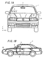
- Figs. 1A and 1B show an exemplary vehicle 1 equipped with a night vision apparatus for a vehicle, as a preferable example of a night vision apparatus according to the invention.
- Fig. 1A is a schematic front view.
- Fig. 1B is a schematic side view.
- headlamps 2 are arranged as illuminating devices in the front portion of the vehicle 1.
- the headlamps 2 are constituted by high-beam light sources 2A, low-beam light sources 2B, and infrared light sources 2C.
- the infrared light sources 2C are arranged on the center side of the vehicle.
- an imaging camera 3 having a sensitivity over a range from the visible light region to the infrared light region is disposed at a rearview mirror portion in the front portion of the driver's seat inside the vehicle 1. That is to say, the imaging camera 3 detects light over a range from the visible light region to the infrared light region.
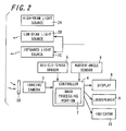
- a controller 4 is disposed inside the vehicle. Asshown in Fig. 2 , a vehicle-speed signal from a vehicle-speed sensor 5, a rudder-angle signal from a rudder-angle sensor 6, and an image signal from the imaging camera 3 are inputted to the controller 4.
- the controller 4 has an image processing portion 7.
- the image processing portion 7 processes an image signal from the imaging camera 3, and outputs the processed signal to a display 8 functioning as an image display portion that is installed in the front portion of the driver's seat inside the vehicle 1.
- a display 8 functioning as an image display portion that is installed in the front portion of the driver's seat inside the vehicle 1.
- an image based on video captured by the imaging camera 3 is displayed on the display 8.
- the controller 4 has a function of changing the orientation of the imaging camera 3 based on a vehicle-speed signal from the vehicle-speed sensor 5 and a rudder-angle signal from the rudder-angle sensor 6.
- the controller 4 can also send a signal as appropriate to warning notification means such as a loudspeaker 9 or an indicator 10, for example, in a case where an obstacle such as a pedestrian exists in front of the vehicle.
- Fig. 2 an example is shown in which an output image is outputted to the display 8 functioning as an image display portion.
- the output image can be outputted not only to the image display portion, but also to a vehicle control system or to a storage apparatus installed in the vehicle. Also, the output image can be transmitted to a transmission system such as a navigation system.
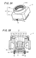
- Fig. 3A shows a schematic perspective view of the detail of the imaging camera 3.
- Fig. 3B shows a cross-sectional view taken along line A-A in Fig. 3A .
- the imaging camera 3 includes a lens member 12 (a first lens 12a, a second lens 12b, and a third lens 12c) that mainly condenses light from a subject, an imaging element 13 on which an image of light from the lens member 12 is formed and converted into an electric signal, and an imaging substrate 14 on which the imaging element 13 is mounted.
- the lens member 12 and the imaging substrate 14 are overlaid with a predetermined gap interposed therebetween, and fixed with fixing pins 18.
- the first lens 12a is in contact with a face of a lens holding portion 15a of a front case 15 on the side of a subject, and pressed by a retainer 23 from the side of a subject.
- the retainer 23 is fixed on the side face of the lens holding portion 15a, for example, with an adhesive or a solder.
- the second lens 12b and the third lens 12c are press-fitted into an opening portion 15b that is open in the lens holding portion 15a, and fixed, for example, with an adhesive or a solder.
- a mask or an aperture may be provided at an appropriate position of the lens member 12, or the outer circumference of the first lens 12a may be fixed by the lens holding portion 15a as the second lens 12b and the like.
- the imaging element 13 is constituted by, for example, a CCD (charge coupled device) image sensor, or a CMOS (complementary MOS) image sensor.
- the imaging element 13 is accommodated in a cavity 24a of a sub-substrate 24, and sealed by a glass rid 25.
- electronic components such as an IC, a capacitor, a coil, and a resistor, for processing an electric signal from the imaging element 13, a connector (not shown) for connecting a cable (not shown) that connects the imaging substrate 14 and an ECU (not shown), and the like are arranged.
- the cable connected to the connector (not shown) is connected to an external connector that is inserted into and fixed at a back face case (not shown), and further extended to an external cable.
- a filter layer is formed on one main face of a flat plate made of glass.
- borosilicate glass can be used in which silica is 10%, boron oxide is 10%, barium oxide is 2%, antimony oxide is 2%, titanium oxide is 2%, and zinc oxide is 20%.
- the optical band elimination filter is configured such that on one main face of the borosilicate glass flat plate, sequentially are formed one layer of aluminum oxide (thickness 58 nm), five layers, each consisting of titanium oxide (thickness 83 nm) and silica (thickness 130 nm), in which the titanium oxide and the silica alternate, one layer of titanium oxide (thickness 83 nm), and one layer of aluminum oxide (thickness 58 nm).
- this optical band elimination filter When the wavelength at which the blocking ratio is a half maximum at both ends of a light-blockingband is taken as a cutoff wavelength, this optical band elimination filter has an optical property in which the light-blocking band has a center wavelength of 570 nm, and cutoff wavelengths at both ends of 530 nm and 610 nm respectively.
- the optical band elimination filter described above has the configuration in which the filter layer is formed only on one main face of the flat plate.
- the configuration is not limited to this, and the filter layer may be formed on both main faces of the flat plate.
- the filter layer that is formed on one main face is configured such that the light-blocking band has cutoff wavelengths of 530 nm and 580 nm
- the filter layer that is formed on the other main face is configured such that the light-blocking band has cutoff wavelengths of 560 nm and 610 nm.
- an optical band elimination filter is obtained that has an optical property in which the light-blocking band has cutoff wavelengths at both ends of 530 nm and 610 nm respectively for light passing from one main face to the other main face.
- the optical band elimination filter also can be configured by forming a filter layer on a main face of the first lens 12a, the second lens 12b, or the third lens 12c.
- the optical band elimination filter also can be configured by forming a filter layer on a main face of the glass rid 25 that is attached on the upper face of the sub-substrate 24 so as to seal the imaging element 13, or by forming a filter layer on a surface of a microlens (not shown) on the surface of the imaging element 13.
- Figs. 4A and 4B show an exemplary spectrum of light that is emitted from the headlamps 2 and received by the imaging camera 3.
- the imaging camera 3 receives both a spectrum of reflected light that has a plurality of peaks mainly in the visible light region (380 to 780 nm), is emitted from the low-beam light sources 2B for obtaining information on the vicinity of the vehicle when recognizing a white line or the like, and is reflected by an object, and a spectrum of reflected light that has peaks in the infrared light region (780 nm or more), is emitted from the infrared light sources 2C for obtaining information on a distant area that is not visible at night, and is reflected by an object.
- the intensity of reflected light that is received by the imaging camera 3 is not determined only based on the intensity of light that is emitted from a light source, but depends also on the distance between the light source and an object. More specifically, the intensity is lowered as the distance between the light source and the object increases. Thus, the sensitivity to the light from the infrared light sources 2C for viewing a distant object tends to be lower than that to the light from the low-beam light sources 2B for viewing an object around the vehicle.
- the optical band elimination filter 30 is disposed between the lens member 12 and the imaging element 13.
- Fig. 5 shows an example of the transmission property of the optical band elimination filter 30.
- the optical band elimination filter 30 in Fig. 5 has a half maximum d of the blocking ratio in 530 to 610 nm in the light-blocking band.
- the optical band elimination filter 30 in a case where the optical band elimination filter 30 is not used, or in a case where no peak can be cut, the image intensity of information on the vicinity of the apparatus based on light that is emitted from the low-beam light sources 2B increases, and thus an image of information on a distant area based on light that is emitted from the infrared light sources 2C becomes relatively less visible.
- detection of an obstacle around the vehicle and recognition of a white line, which otherwise would be displayed based on a signal in the visible light region cannot be performed.
- the optical band elimination filter 30 preferably cuts only two peaks, namely the peak having the highest intensity and the peak having the second highest intensity, among the five or more peaks, because this processing makes it possible to reduce the peaks so as to achieve matching of the intensity in the visible light region with that in the infrared light region while keeping the sensitivity in the visible light region.
- High intensity discharge lamps have various wavelength spectra that vary depending on the type of the light sources, as shown in Figs. 4A and 4B .
- the light-blocking band of the optical band elimination filter 30 preferably has a half maximum d of the blocking ratio in 490 to 570 nm, or 530 to 610 nm in the light-blocking band, because this configuration makes it possible to effectively achieve balance of the image intensity in the visible light region with that in the infrared light region while keeping the sensitivity in the visible light region.
- the light-blocking band width of the optical band elimination filter 30 is preferably 50 to 100 nm, because this band width increases the sensitivity of an image in the visible light region.
- the infrared light sources 2C are provided as dedicated light sources that are different from the low-beam light sources 2B, but a configuration also may be adopted in which the infrared light sources 2C are used also as the low-beam light sources 2B.
- the shape of the filter of the infrared light sources 2C is not limited to those described above.
- the night vision apparatus of the invention is not limited to a night vision apparatus for a vehicle, and can be also applied to a monitoring camera and the like appropriately.
- the night vision apparatus of the invention can be equipped inavehicle.
- a vehicle equipped with the night vision apparatus of the invention can let the driver visually confirm directly image information obtained by the night vision apparatus, can give, by means of sounds, light, or vibrations, the driver warning to the effect that an obstacle, another vehicle, or the like on the road is detected, for example, and can control a movement of the vehicle based on image information obtained by the night vision apparatus, as in vehicles equipped with conventional night vision apparatuses.
- the vehicle equipped with the night vision apparatus of the invention can be realized by equipping a vehicle with the night vision apparatus of the invention, specific examples of the vehicle including not only railroad trains, electric railcars, automobiles, and other passenger vehicles, and freight cars, but also bicycles, motorized bicycles, rides in theme-parks, and carts in golf courses, for example.
- the night vision apparatus of the invention can be equipped in a small boat.
- a small boat equipped with the night vision apparatus of the invention can let the operator visually confirm directly image information obtained by the night vision apparatus, and can give, by means of sounds, light, or vibrations, the operator warning to the effect that an obstacle such as a sunken rock, another boat, another small boat, or the like is detected, for example, as in conventional cases.
- the small boat equipped with the night vision apparatus of the invention can be realized by equipping a small boat with the night vision apparatus of the invention, specific examples of the small boat including boats that can be operated with a license for small boats or without a license, such as hand rowing boats, dinghies, wet bikes, small bass boats equipped with an outboard motor, inflatable boats (rubber dinghies) equipped with an outboard motor, fishing ships, leisure fishing boats, workboats, houseboats, towing boats, sports boats, fishing boats, yachts, offshore yachts, and cruisers, which have a gross tonnage of less than 20 tons, and pleasure boats having a gross tonnage of 20 tons or more.
- boats that can be operated with a license for small boats or without a license such as hand rowing boats, dinghies, wet bikes, small bass boats equipped with an outboard motor, inflatable boats (rubber dinghies) equipped with an outboard motor, fishing ships, leisure fishing boats, workboats, houseboats, towing boats, sports boats, fishing boats, yacht
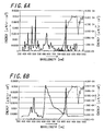
- a vehicle was prepared that had headlamps as light sources with the light-emitting property shown in Figs. 6A and 6B and in which an optical band elimination filter with the light-blocking band in Table 1 was disposed inside an imaging camera. At night, this vehicle was stopped on a road with a white line drawn on the left side, and a person in white clothes was made to stand as an obstacle near the white line. Both the low-beam light sources and the infrared light sources of the vehicle were on.
- Sample 3 corresponds to light of a high intensity discharge lamp (HID illumination light source 1: HID1) received with the wavelength spectrum in Fig. 4A , and passed through the optical band elimination filter in Fig. 5 to be corrected to have the wavelength spectrum in Fig. 6A .
- Sample 4 corresponds to light of a high intensity discharge lamp (HID illumination light source 2: HID2) received with the wavelength spectrum in Fig.
Abstract
Description
- The present invention relates to a night vision apparatus, and in particular relates to a night vision apparatus suitable as a night vision apparatus for a vehicle, that improves the field of view at night or the like using light ranging from the visible light region to the infrared light region.
- Conventionally, for the purpose of assisting the visibility when driving at night, a night vision apparatus for a vehicle is known in which light is irradiated using an illuminating device such as a headlamp that emits visible light and infrared light in a traveling direction such as the forward direction of the vehicle, an image of light reflected from a subject is captured using an imaging element of a camera, and the image is displayed on a monitor inside the vehicle.
- For example, Japanese Unexamined Patent Publication
JP-A 2004-142561 - Furthermore, Japanese Unexamined Patent Publication
JP-A 2003-259363 - Moreover, in these night vision apparatuses, a night vision apparatus for a vehicle is being developed in which infrared light is used for capturing information on a distant area that is not visible, visible light is used for capturing information on the vicinity of the vehicle, and both pieces of information are displayed on a display inside the vehicle.
- However, in a case where light throughout the entire visible light region is absorbed as in
JP-A 2004-142561 JP-A 2003-259363 Figs. 4A and 4B . Thus, it cannot be said that an obstacle around the vehicle and a white line can be sufficiently confirmed. - The invention has been made in order to solve the problems described above, and it is an object thereof to provide a night vision apparatus that can assist in enlarging the field of view at night or in bad weather, and can obtain image with high sensitivity over a range from a distant area to an area close to the apparatus by receiving light ranging from the visible light region to the infrared light region.
- The invention is directed to a night vision apparatus, comprising:
- an illuminating device having one light source or two or more light sources, to emit light ranging from a visible light region to an infrared light region, a plurality of peaks existing in a wavelength spectrum in the visible light region;
- an imaging camera that receives light emitted from the illuminating device; and
- an optical band elimination filter that blocks only a part of peaks among the plurality of peaks,
- wherein an output image is obtained based on an image captured by the imaging camera through the optical band elimination filter.
- Herein, it is preferable that a number of the peaks is at least three, and the optical band elimination filter cuts only a peak having a highest intensity among the at least three peaks. Furthermore, it is preferable that a number of the peaks is at least three, and the optical band elimination filter cuts only a peak having a highest intensity and a peak having a second highest intensity among the at least three peaks.
- Furthermore, it is preferable that in a case where the light source is a high intensity discharge lamp (HID illumination light source), a light-blocking band of the optical band elimination filter has a half maximum of a blocking ratio in a wavelength band of 490 to 570 nm, or 530 to 610 nm.
- Furthermore, it is preferable that a light-blocking band width of the optical band elimination filter is 50 to 100 nm.
- Furthermore, it is preferable that the optical band elimination filter has two light-blocking bands that differ in cutoff wavelength, which is a wavelength at which a blocking ratio is a half maximum.
- Furthermore, the invention is directed to a vehicle equipped with a night vision apparatus, in which the night vision apparatus described above is equipped.
- Furthermore, the invention is directed to a small boat equipped with a night vision apparatus, in which the night vision apparatus described above is equipped.
- According to the invention, with respect to the illuminating device that emits light ranging from a visible light region to an infrared light region, the optical band elimination filter is used that cuts only a part of peaks among a plurality of peaks in the visible light region. Thus, it is possible to achieve balance of the peak intensity in the visible light region with that in the infrared light region while keeping the peak sensitivity in the visible light region. Accordingly, it is possible to obtain, with high sensitivity, both a distant image based on the peak intensity in the infrared light region and an image near the apparatus based on the peak intensity in the visible light region. Furthermore, when the optical band elimination filter is used, no halation is caused in the night vision apparatus by visible light that is emitted from the outside such as a low beam of an oncoming vehicle. Thus, it is possible to suppress an obstacle's (e.g., a pedestrian) becoming less visible around the vehicle that is equipped with the night vision apparatus of the invention. Accordingly, an output image necessary for display on the image display portion and the like becomes clear over a range from an area closer to the apparatus to a distant area, and thus the field of view of the night vision apparatus is enlarged.
- The peak intensity of light in the visible light region emitted from a low beam received by the imaging camera tends to be higher than that of light in the infrared light region, because objects to be detected are closer to the vehicle in the case of the low beam. Conversely, the intensity of light received from the infrared light source tends to be lower. The detail of the wavelength spectrum of light that is emitted from the low-beam light source of a headlamp shows that there are several high intensity peaks throughout the entire wavelength of the visible light region, and information on the vicinity of the vehicle can be obtained from a low beam based on the peak intensity.
- In the invention, the peak intensity of the wavelength at which peaks exist is cut or reduced not on all high intensity peaks from the low-beam light source, but on only a part of peaks among high intensity peaks that cause high intensity increasing the image peak intensity. Thus, it is possible to achieve balance between the image sensitivity in the visible light region and the image sensitivity in the infrared light region, and thus to clearly confirm information in a wide region ranging from the vicinity of the vehicle to a distant area.
- Herein, it is preferable that the number of the peaks is at least three, and the optical band elimination filter cuts only a peak having the highest intensity among the at least three peaks, or only a peak having the highest intensity and a peak having the second highest intensity among the at least three peaks, because this configuration makes it possible to achieve balance of the image intensity in the visible light region with that in the infrared light region while keeping the image sensitivity in the visible light region.
- Furthermore, it is preferable that in a case where the light source is a high intensity discharge lamp (HID illumination light source), a light-blocking band of the optical band elimination filter has a half maximum of a blocking ratio in a wavelength band of 490 to 570 nm, or 530 to 610 nm, because this configuration makes it possible to achieve matching of the image intensity in the visible light region with that in the infrared light region while keeping the sensitivity in the visible light region.
- Furthermore, it is preferable that a light-blocking band width of the optical band elimination filter is 50 to 100 nm, because this configuration does not reduce the sensitivity in the visible light region.
- Furthermore, the optical band elimination filter has two light-blocking bands that differ in cutoff wavelength, which is a wavelength at which a blocking ratio is a half maximum, so that this configuration makes it possible to cut peaks in two light-blocking bands.
- Furthermore, in a case where a vehicle is equipped with the night vision apparatus of the invention, it is possible to let the driver visually confirm directly image information obtained by the night vision apparatus, to give, by means of sounds, light, or vibrations, the driver warning to the effect that an obstacle, another vehicle, or the like on the road is detected, for example, and to control a movement of the vehicle based on image information obtained by the night vision apparatus.
- Furthermore, in a case where a small boat is equipped with the night vision apparatus of the invention, it is possible to let the operator visually confirm directly image information obtained by the night vision apparatus, and to give, by means of sounds, light, or vibrations, the operator warning to the effect that an obstacle such as a sunken rock, another boat, another small boat, or the like is detected, for example.
- Other and further objects, features, and advantages of the invention will be more explicit from the following detailed description taken with reference to the drawings.
-
Fig. 1A is a schematic front view of a vehicle equipped with a night vision apparatus for a vehicle which is a preferable example of a night vision apparatus according to the invention, andFig. 1B is a schematic side view of the vehicle equipped with the night vision apparatus for a vehicle. -
Fig. 2 is a block circuit diagram of the night vision apparatus for a vehicle with which the vehicle inFigs. 1A and 1B is equipped. -
Fig. 3A is a cross sectional view showing an example of infrared light sources according to the invention andFig. 3B is an exploded perspective view thereof. -
Fig. 4A is a wavelength spectrum showing a light-emitting property of an HID lamp, andFig. 4A is a wavelength spectrum showing a light-emitting property of another HID lamp. -
Fig. 5 is a wavelength spectrum showing an example of transmission property of an optical band elimination filter. -
Fig. 6A is a wavelength spectrum of corrected light obtained by letting light of the HID lamp inFig. 4A pass through the optical band elimination filter having the transmission property inFig. 5 , andFig. 6B is a wavelength spectrum of corrected light obtained by letting light of the HID lamp inFig. 4B pass through the optical band elimination filter having the transmission property inFig. 5 . - Now referring to the drawings, preferred embodiments of the invention are described below.
-
Figs. 1A and 1B show an exemplary vehicle 1 equipped with a night vision apparatus for a vehicle, as a preferable example of a night vision apparatus according to the invention.Fig. 1A is a schematic front view.Fig. 1B is a schematic side view. - According to
Figs. 1A and 1B ,headlamps 2 are arranged as illuminating devices in the front portion of the vehicle 1. Theheadlamps 2 are constituted by high-beam light sources 2A, low-beam light sources 2B, and infraredlight sources 2C. Theinfrared light sources 2C are arranged on the center side of the vehicle. - Furthermore, as shown in
Figs. 1A and 1B , animaging camera 3 having a sensitivity over a range from the visible light region to the infrared light region is disposed at a rearview mirror portion in the front portion of the driver's seat inside the vehicle 1. That is to say, theimaging camera 3 detects light over a range from the visible light region to the infrared light region. Acontroller 4 is disposed inside the vehicle. Asshown inFig. 2 , a vehicle-speed signal from a vehicle-speed sensor 5, a rudder-angle signal from a rudder-angle sensor 6, and an image signal from theimaging camera 3 are inputted to thecontroller 4. - The
controller 4 has animage processing portion 7. Theimage processing portion 7 processes an image signal from theimaging camera 3, and outputs the processed signal to adisplay 8 functioning as an image display portion that is installed in the front portion of the driver's seat inside the vehicle 1. Thus, an image based on video captured by theimaging camera 3 is displayed on thedisplay 8. Furthermore, thecontroller 4 has a function of changing the orientation of theimaging camera 3 based on a vehicle-speed signal from the vehicle-speed sensor 5 and a rudder-angle signal from the rudder-angle sensor 6. Thecontroller 4 can also send a signal as appropriate to warning notification means such as aloudspeaker 9 or anindicator 10, for example, in a case where an obstacle such as a pedestrian exists in front of the vehicle. - In
Fig. 2 , an example is shown in which an output image is outputted to thedisplay 8 functioning as an image display portion. However, the invention is not limited to this example. The output image can be outputted not only to the image display portion, but also to a vehicle control system or to a storage apparatus installed in the vehicle. Also, the output image can be transmitted to a transmission system such as a navigation system. -
Fig. 3A shows a schematic perspective view of the detail of theimaging camera 3.Fig. 3B shows a cross-sectional view taken along line A-A inFig. 3A . Theimaging camera 3 includes a lens member 12 (afirst lens 12a, asecond lens 12b, and athird lens 12c) that mainly condenses light from a subject, animaging element 13 on which an image of light from thelens member 12 is formed and converted into an electric signal, and animaging substrate 14 on which theimaging element 13 is mounted. Thelens member 12 and theimaging substrate 14 are overlaid with a predetermined gap interposed therebetween, and fixed with fixing pins 18. Thefirst lens 12a is in contact with a face of alens holding portion 15a of afront case 15 on the side of a subject, and pressed by aretainer 23 from the side of a subject. - The
retainer 23 is fixed on the side face of thelens holding portion 15a, for example, with an adhesive or a solder. Thesecond lens 12b and thethird lens 12c are press-fitted into anopening portion 15b that is open in thelens holding portion 15a, and fixed, for example, with an adhesive or a solder. A mask or an aperture may be provided at an appropriate position of thelens member 12, or the outer circumference of thefirst lens 12a may be fixed by thelens holding portion 15a as thesecond lens 12b and the like. - The
imaging element 13 is constituted by, for example, a CCD (charge coupled device) image sensor, or a CMOS (complementary MOS) image sensor. Theimaging element 13 is accommodated in acavity 24a of a sub-substrate 24, and sealed by a glass rid 25. On a face of theimaging substrate 14 opposite to the side of theimaging element 13, electronic components (not shown), such as an IC, a capacitor, a coil, and a resistor, for processing an electric signal from theimaging element 13, a connector (not shown) for connecting a cable (not shown) that connects theimaging substrate 14 and an ECU (not shown), and the like are arranged. The cable connected to the connector (not shown) is connected to an external connector that is inserted into and fixed at a back face case (not shown), and further extended to an external cable. - The invention is significantly characterized in that an optical,
band elimination filter 30 is disposed in a portion from thelens member 12 to theimaging substrate 14 of theimaging camera 3. InFigs. 3A and 3B , the opticalband elimination filter 30 is formed between thelens member 12 and theimaging substrate 14. However, the invention is not limited to this, and the outer circumference of thefirst lens 12a may be formed between lenses such as thesecond lens 12b or in front of thelens member 12. - More specifically, in the optical
band elimination filter 30, a filter layer is formed on one main face of a flat plate made of glass. As the glass material used for the flat plate, borosilicate glass can be used in which silica is 10%, boron oxide is 10%, barium oxide is 2%, antimony oxide is 2%, titanium oxide is 2%, and zinc oxide is 20%. The optical band elimination filter is configured such that on one main face of the borosilicate glass flat plate, sequentially are formed one layer of aluminum oxide (thickness 58 nm), five layers, each consisting of titanium oxide (thickness 83 nm) and silica (thickness 130 nm), in which the titanium oxide and the silica alternate, one layer of titanium oxide (thickness 83 nm), and one layer of aluminum oxide (thickness 58 nm). When the wavelength at which the blocking ratio is a half maximum at both ends of a light-blockingband is taken as a cutoff wavelength, this optical band elimination filter has an optical property in which the light-blocking band has a center wavelength of 570 nm, and cutoff wavelengths at both ends of 530 nm and 610 nm respectively. - The optical band elimination filter described above has the configuration in which the filter layer is formed only on one main face of the flat plate. However, the configuration is not limited to this, and the filter layer may be formed on both main faces of the flat plate. In this case, for example, the filter layer that is formed on one main face is configured such that the light-blocking band has cutoff wavelengths of 530 nm and 580 nm, and the filter layer that is formed on the other main face is configured such that the light-blocking band has cutoff wavelengths of 560 nm and 610 nm. Thus, an optical band elimination filter is obtained that has an optical property in which the light-blocking band has cutoff wavelengths at both ends of 530 nm and 610 nm respectively for light passing from one main face to the other main face.
- Furthermore, the optical band elimination filter also can be configured by forming a filter layer on a main face of the
first lens 12a, thesecond lens 12b, or thethird lens 12c. The optical band elimination filter also can be configured by forming a filter layer on a main face of the glass rid 25 that is attached on the upper face of the sub-substrate 24 so as to seal theimaging element 13, or by forming a filter layer on a surface of a microlens (not shown) on the surface of theimaging element 13. -
Figs. 4A and 4B show an exemplary spectrum of light that is emitted from theheadlamps 2 and received by theimaging camera 3. As shown inFigs. 4A and 4B , theimaging camera 3 receives both a spectrum of reflected light that has a plurality of peaks mainly in the visible light region (380 to 780 nm), is emitted from the low-beam light sources 2B for obtaining information on the vicinity of the vehicle when recognizing a white line or the like, and is reflected by an object, and a spectrum of reflected light that has peaks in the infrared light region (780 nm or more), is emitted from theinfrared light sources 2C for obtaining information on a distant area that is not visible at night, and is reflected by an object. Although unable to be shown, the intensity of reflected light that is received by theimaging camera 3 is not determined only based on the intensity of light that is emitted from a light source, but depends also on the distance between the light source and an object. More specifically, the intensity is lowered as the distance between the light source and the object increases. Thus, the sensitivity to the light from theinfrared light sources 2C for viewing a distant object tends to be lower than that to the light from the low-beam light sources 2B for viewing an object around the vehicle. - Here, in both
Figs. 4A and 4B , both a spectrum of a high intensity discharge lamp (HID illumination light source) used as the low-beam light sources 2B and a spectrum of a halogen lamp used as theinfrared light sources 2C are received. In the case of light from an HID illumination light source, the waveform of a spectrum varies depending on the type of the light source.Fig. 4A shows an example of a metal halide lamp in which there are eight peaks in the visible light region.Fig. 4B shows an example of a mercury lamp in which there are four peaks in the visible light region. - According to
Figs. 3A and 3B , the opticalband elimination filter 30 is disposed between thelens member 12 and theimaging element 13.Fig. 5 shows an example of the transmission property of the opticalband elimination filter 30. The opticalband elimination filter 30 inFig. 5 has a half maximum d of the blocking ratio in 530 to 610 nm in the light-blocking band. - When light in
Figs. 4A and 4B received by theimaging camera 3 is passed through the opticalband elimination filter 30 inFig. 5 , among peaks (eight peaks inFig. 4A , and four peaks inFig. 4B ) in the wavelength spectra received by theimaging camera 3, only a part of the peaks (two peaks inFig. 4A , and one peak inFig. 4B ) is cut in such a manner that the energy intensity is 1.0×10⁻⁵ µW/sr.cm2 or less. Accordingly, the wavelength spectra are converted into those as shown inFigs. 6A and 6B , and displayed on thedisplay 8. - As a result, it is possible to adj ust light of the
headlamps 2, with respect to the image intensity in the infrared light region, while securing the image sensitivity in the visible light region. Thus, a clear image with high sensitivity can be displayed over a range from the visible light region to the infrared light region. - More specifically, in a case where the optical
band elimination filter 30 is not used, or in a case where no peak can be cut, the image intensity of information on the vicinity of the apparatus based on light that is emitted from the low-beam light sources 2B increases, and thus an image of information on a distant area based on light that is emitted from theinfrared light sources 2C becomes relatively less visible. In a case where all peaks that exist in the visible light region are cut by a filter, detection of an obstacle around the vehicle and recognition of a white line, which otherwise would be displayed based on a signal in the visible light region, cannot be performed. - Here, as shown in
Fig. 5 , in a case where there are five or more peaks in the wavelength spectrum of theheadlamps 2, the opticalband elimination filter 30 preferably cuts only two peaks, namely the peak having the highest intensity and the peak having the second highest intensity, among the five or more peaks, because this processing makes it possible to reduce the peaks so as to achieve matching of the intensity in the visible light region with that in the infrared light region while keeping the sensitivity in the visible light region. - High intensity discharge lamps (HID illumination light sources) have various wavelength spectra that vary depending on the type of the light sources, as shown in
Figs. 4A and 4B . In view of the wavelength spectrum of a high intensity discharge lamp (HID illumination light source) that is generally used as the low-beam light sources 2B, the light-blocking band of the opticalband elimination filter 30 preferably has a half maximum d of the blocking ratio in 490 to 570 nm, or 530 to 610 nm in the light-blocking band, because this configuration makes it possible to effectively achieve balance of the image intensity in the visible light region with that in the infrared light region while keeping the sensitivity in the visible light region. Furthermore, the light-blocking band width of the opticalband elimination filter 30 is preferably 50 to 100 nm, because this band width increases the sensitivity of an image in the visible light region. - In this embodiment, a configuration is adopted in which the
infrared light sources 2C are provided as dedicated light sources that are different from the low-beam light sources 2B, but a configuration also may be adopted in which theinfrared light sources 2C are used also as the low-beam light sources 2B. Furthermore, the shape of the filter of theinfrared light sources 2C is not limited to those described above. - The night vision apparatus of the invention is not limited to a night vision apparatus for a vehicle, and can be also applied to a monitoring camera and the like appropriately.
- The night vision apparatus of the invention can be equipped inavehicle. A vehicle equipped with the night vision apparatus of the invention can let the driver visually confirm directly image information obtained by the night vision apparatus, can give, by means of sounds, light, or vibrations, the driver warning to the effect that an obstacle, another vehicle, or the like on the road is detected, for example, and can control a movement of the vehicle based on image information obtained by the night vision apparatus, as in vehicles equipped with conventional night vision apparatuses.
- The vehicle equipped with the night vision apparatus of the invention can be realized by equipping a vehicle with the night vision apparatus of the invention, specific examples of the vehicle including not only railroad trains, electric railcars, automobiles, and other passenger vehicles, and freight cars, but also bicycles, motorized bicycles, rides in theme-parks, and carts in golf courses, for example.
- Moreover, the night vision apparatus of the invention can be equipped in a small boat. A small boat equipped with the night vision apparatus of the invention can let the operator visually confirm directly image information obtained by the night vision apparatus, and can give, by means of sounds, light, or vibrations, the operator warning to the effect that an obstacle such as a sunken rock, another boat, another small boat, or the like is detected, for example, as in conventional cases.
- The small boat equipped with the night vision apparatus of the invention can be realized by equipping a small boat with the night vision apparatus of the invention, specific examples of the small boat including boats that can be operated with a license for small boats or without a license, such as hand rowing boats, dinghies, wet bikes, small bass boats equipped with an outboard motor, inflatable boats (rubber dinghies) equipped with an outboard motor, fishing ships, leisure fishing boats, workboats, houseboats, towing boats, sports boats, fishing boats, yachts, offshore yachts, and cruisers, which have a gross tonnage of less than 20 tons, and pleasure boats having a gross tonnage of 20 tons or more.
- A vehicle was prepared that had headlamps as light sources with the light-emitting property shown in
Figs. 6A and 6B and in which an optical band elimination filter with the light-blocking band in Table 1 was disposed inside an imaging camera. At night, this vehicle was stopped on a road with a white line drawn on the left side, and a person in white clothes was made to stand as an obstacle near the white line. Both the low-beam light sources and the infrared light sources of the vehicle were on. At that time, it was checked whether or not the existence of the person in white clothes was able to be confirmed when the operator was sitting in the driver' s seat of the vehicle and used a display of the night vision apparatus of the vehicle to observe an oncoming vehicle positioned in front of the vehicle with a space of 150 m interposed therebetween in a state where the headlamps of the oncoming vehicle were on. - Furthermore, in a case where the operator was sitting in the driver's seat of this vehicle, and both the low-beam light sources and the infrared light sources of the vehicle were on, an image outputted to the display of the night vision apparatus in the vehicle was confirmed and evaluated to determine whether or not the left white line was able to be confirmed in the image. Table 1 shows the results.
Sample 3 corresponds to light of a high intensity discharge lamp (HID illumination light source 1: HID1) received with the wavelength spectrum inFig. 4A , and passed through the optical band elimination filter inFig. 5 to be corrected to have the wavelength spectrum inFig. 6A .Sample 4 corresponds to light of a high intensity discharge lamp (HID illumination light source 2: HID2) received with the wavelength spectrum inFig. 4B , and passed through the optical band elimination filter inFig. 5 to be corrected to have the wavelength spectrum inFig. 6B .Table 1 Sample No. Type of headlamp Number of peaks in light source Filter blocking band Number of cut peaks Recognition of obstacle Confirmation of white line *1 HID1 8 380-780 8 Excellent Disable 2 HID1 8 490-610 4 Excellent Able 3 HID1 8 530-610 2 Good Good 4 HID1 8 490-570 2 Slightly good Good 5 HID1 8 530-580 1 Able Excellent 6 HID2 4 550-580 1 Good Good 7 LED 2 430-500 1 Good Good *8 HID1 8 - 0 Disable Excellent Symbol "*" indicates a sample outside the scope of the invention - According to the results in Table 1, in
Sample 8 where the optical band elimination filter was not used, it was impossible to confirm the obstacle due to halation. In Sample 1 where all signals in the visible light region were cut, it was impossible to confirm the white line due to difficulty in confirming the vicinity of the vehicle. - Conversely,
Samples 2 to 7 where the optical band elimination filter blocking only a part of a plurality of peaks was provided, it was possible to recognize the obstacle, and to recognize the white line. - The invention may be embodied in other specific forms without departing from the spirit or essential characteristics thereof. The present embodiments are therefore to be considered in all respects as illustrative and not restrictive, the scope of the invention being indicated by the appended claims rather than by the foregoing description and all changes which come within the meaning and the range of equivalency of the claims are therefore intended to be embraced therein.
Claims (10)
- A night vision apparatus, comprising:an illuminating device having one light source or two or more light sources, to emit light ranging from a visible light region to an infrared light region, a plurality of peaks existing in a wavelength spectrum in the visible light region;an imaging camera that receives light emitted from the illuminating device; andan optical band elimination filter that blocks only a part of peaks among the plurality of peaks,wherein an output image is obtained based on an image captured by the imaging camera through the optical band elimination filter.
- The night vision apparatus of claim 1, wherein a number of the peaks is at least three, and the optical band elimination filter cuts only a peak having a highest intensity among the at least three peaks.
- The night vision apparatus of claim 1, wherein a number of the peaks is at least three, and the optical band elimination filter cuts only a peak having a highest intensity and a peak having a second highest intensity among the at least three peaks.
- The night vision apparatus of any one of claims 1 to 3, wherein the light sources comprise a high intensity discharge lamp and a halogen lamp.
- The night vision apparatus of claim 4, wherein a light-blocking band of the optical band elimination filter has a half maximum of a blocking ratio in a wavelength band of 490 to 570 nm.
- The night vision apparatus of claim 4, wherein a light-blocking band of the optical band elimination filter has a half maximum of a blocking ratio in a wavelength band of 530 to 610 nm.
- The night vision apparatus of claim 5 or 6, wherein a light-blocking band width of the optical band elimination filter is 50 to 100 nm.
- The night vision apparatus of claim 1, wherein the optical band elimination filter has two light-blocking bands that differ in cutoff wavelength, which is a wavelength at which a blocking ratio is a half maximum.
- A vehicle equipped with a night vision apparatus, in which the night vision apparatus of any one of claims 1 to 8 is equipped.
- A small boat equipped with a night vision apparatus, in which the night vision apparatus of any one of claims 1 to 8 is equipped.
Applications Claiming Priority (2)
| Application Number | Priority Date | Filing Date | Title |
|---|---|---|---|
| JP2006087805 | 2006-03-28 | ||
| PCT/JP2007/056266 WO2007111317A1 (en) | 2006-03-28 | 2007-03-26 | Night vision device |
Publications (3)
| Publication Number | Publication Date |
|---|---|
| EP2007132A1 true EP2007132A1 (en) | 2008-12-24 |
| EP2007132A4 EP2007132A4 (en) | 2009-05-13 |
| EP2007132B1 EP2007132B1 (en) | 2013-05-08 |
Family
ID=38541234
Family Applications (1)
| Application Number | Title | Priority Date | Filing Date |
|---|---|---|---|
| EP07739704.0A Expired - Fee Related EP2007132B1 (en) | 2006-03-28 | 2007-03-26 | Night vision device |
Country Status (5)
| Country | Link |
|---|---|
| US (1) | US7767964B2 (en) |
| EP (1) | EP2007132B1 (en) |
| JP (1) | JP4594423B2 (en) |
| CN (1) | CN101411178B (en) |
| WO (1) | WO2007111317A1 (en) |
Families Citing this family (11)
| Publication number | Priority date | Publication date | Assignee | Title |
|---|---|---|---|---|
| KR20110140010A (en) * | 2010-06-24 | 2011-12-30 | 삼성전자주식회사 | Image sensor using near infrared signal |
| CN203445943U (en) * | 2010-08-20 | 2014-02-19 | 株式会社日立国际电气 | Image monitoring system and camera |
| SG192581A1 (en) * | 2011-02-28 | 2013-09-30 | Univ Florida | Infrared pass visible blocker for upconversion devices |
| US20130083195A1 (en) * | 2011-09-30 | 2013-04-04 | Jeffrey Thomas Remillard | Polarization-based anti-blinding night vision system, vehicle comprising same, and method therefor |
| JP6205923B2 (en) * | 2013-07-11 | 2017-10-04 | 株式会社デンソー | Driving support device |
| DE102014115292A1 (en) * | 2014-10-21 | 2016-04-21 | Connaught Electronics Ltd. | Method for providing image files from a camera system, camera system and motor vehicle |
| DE102015005697B4 (en) * | 2015-05-04 | 2019-10-02 | Mekra Lang Gmbh & Co. Kg | Camera system for a motor vehicle |
| US9842868B2 (en) * | 2015-10-26 | 2017-12-12 | Sensors Unlimited, Inc. | Quantum efficiency (QE) restricted infrared focal plane arrays |
| CN105785990B (en) * | 2016-02-26 | 2019-01-11 | 江苏科技大学 | Ship mooring system and obstacle recognition method based on panoramic looking-around |
| CN105799593B (en) * | 2016-03-18 | 2019-01-25 | 京东方科技集团股份有限公司 | Vehicle auxiliary travelling device |
| JP6181278B1 (en) * | 2016-12-22 | 2017-08-16 | Jig−Saw株式会社 | Head-mounted image presentation device having a visible light wavelength converter |
Citations (5)
| Publication number | Priority date | Publication date | Assignee | Title |
|---|---|---|---|---|
| JPS56135809A (en) * | 1980-03-26 | 1981-10-23 | Hino Kinzoku Sangyo Kk | Filter for astronominal observation |
| US20030107323A1 (en) * | 1998-09-18 | 2003-06-12 | Stam Joseph S. | Headlamp control to prevent glare |
| US20040179283A1 (en) * | 2003-03-14 | 2004-09-16 | Jones Michael R. | Dye-based filter |
| US20050023465A1 (en) * | 2003-07-30 | 2005-02-03 | Helmuth Eggers | Device for improving visibility in motor vehicles |
| WO2005066684A1 (en) * | 2004-01-10 | 2005-07-21 | Robert Bosch Gmbh | Night vision system for motor vehicles, comprising a partial optical filter |
Family Cites Families (7)
| Publication number | Priority date | Publication date | Assignee | Title |
|---|---|---|---|---|
| JPH10108206A (en) * | 1996-09-27 | 1998-04-24 | Toshiba Lighting & Technol Corp | Color video camera, video doorphone and monitor |
| JP2002320139A (en) | 2001-04-19 | 2002-10-31 | Matsushita Electric Ind Co Ltd | Camera |
| JP2003259363A (en) | 2002-02-27 | 2003-09-12 | Denso Corp | Night vision apparatus |
| FR2839138B1 (en) * | 2002-04-30 | 2005-01-07 | Valeo Vision | BIFUNCTION PROJECTOR DEVICE FOR A MOTOR VEHICLE |
| JP2004032243A (en) | 2002-06-25 | 2004-01-29 | Sanyo Electric Co Ltd | Imaging apparatus and optical filter |
| JP2004142561A (en) * | 2002-10-23 | 2004-05-20 | Ichikoh Ind Ltd | Infrared lighting source and lighting implement for vehicle |
| JP2005032625A (en) * | 2003-07-08 | 2005-02-03 | Ichikoh Ind Ltd | Projection device of night vision equipment for vehicle |
-
2007
- 2007-03-26 WO PCT/JP2007/056266 patent/WO2007111317A1/en active Application Filing
- 2007-03-26 JP JP2008507497A patent/JP4594423B2/en not_active Expired - Fee Related
- 2007-03-26 CN CN2007800110067A patent/CN101411178B/en not_active Expired - Fee Related
- 2007-03-26 EP EP07739704.0A patent/EP2007132B1/en not_active Expired - Fee Related
- 2007-03-26 US US12/294,606 patent/US7767964B2/en not_active Expired - Fee Related
Patent Citations (5)
| Publication number | Priority date | Publication date | Assignee | Title |
|---|---|---|---|---|
| JPS56135809A (en) * | 1980-03-26 | 1981-10-23 | Hino Kinzoku Sangyo Kk | Filter for astronominal observation |
| US20030107323A1 (en) * | 1998-09-18 | 2003-06-12 | Stam Joseph S. | Headlamp control to prevent glare |
| US20040179283A1 (en) * | 2003-03-14 | 2004-09-16 | Jones Michael R. | Dye-based filter |
| US20050023465A1 (en) * | 2003-07-30 | 2005-02-03 | Helmuth Eggers | Device for improving visibility in motor vehicles |
| WO2005066684A1 (en) * | 2004-01-10 | 2005-07-21 | Robert Bosch Gmbh | Night vision system for motor vehicles, comprising a partial optical filter |
Non-Patent Citations (1)
| Title |
|---|
| See also references of WO2007111317A1 * |
Also Published As
| Publication number | Publication date |
|---|---|
| WO2007111317A1 (en) | 2007-10-04 |
| EP2007132A4 (en) | 2009-05-13 |
| CN101411178A (en) | 2009-04-15 |
| JP4594423B2 (en) | 2010-12-08 |
| EP2007132B1 (en) | 2013-05-08 |
| CN101411178B (en) | 2011-10-05 |
| US20090101820A1 (en) | 2009-04-23 |
| JPWO2007111317A1 (en) | 2009-08-13 |
| US7767964B2 (en) | 2010-08-03 |
Similar Documents
| Publication | Publication Date | Title |
|---|---|---|
| EP2007132B1 (en) | Night vision device | |
| US20200398753A1 (en) | System and method for guiding reversing of a vehicle toward a trailer hitch | |
| US7619680B1 (en) | Vehicular imaging system with selective infrared filtering and supplemental illumination | |
| CN100413324C (en) | On-vehicle night vision camera system, display device and display method | |
| US7889230B2 (en) | Vehicle rear side video monitoring system | |
| US20180015879A1 (en) | Side-view mirror camera system for vehicle | |
| JP2006248374A (en) | Vehicle safety confirmation device and head-up display | |
| JPH05294183A (en) | On-vehicle monitoring camera device | |
| JP4688196B2 (en) | Night vision system for automobile | |
| JP2007091186A (en) | Photographing/display method of peripheral state of vehicle and photographing/display system | |
| US11146715B2 (en) | Camera system, driver/passenger monitoring system, moving vehicle, image capturing method, and non-transitory storage medium | |
| JP2005051790A (en) | Device for improving visibility in vehicle | |
| US20070272837A1 (en) | Vehicle occupant detection device | |
| JP2009029350A (en) | Occupant detection device for vehicle | |
| JP3764317B2 (en) | In-vehicle peripheral visual recognition device | |
| JP2007050749A (en) | Automobile periphery monitoring device | |
| JP2005001948A (en) | Laminated glass and its manufacturing method | |
| JP4504085B2 (en) | Rearview mirror with surveillance camera | |
| TWM600267U (en) | Driving situation monitoring and warning system | |
| WO2019177036A1 (en) | Vehicle imaging system | |
| KR20230131399A (en) | Vehicle recognize apparatus | |
| JP4620640B2 (en) | Headlight module | |
| JP2004231051A (en) | Outside mirror for automobile | |
| JP2004051057A (en) | Night vision device for vehicle | |
| CN108791153A (en) | Automobile A column is imaged arrangement for perspective immediately |
Legal Events
| Date | Code | Title | Description |
|---|---|---|---|
| PUAI | Public reference made under article 153(3) epc to a published international application that has entered the european phase |
Free format text: ORIGINAL CODE: 0009012 |
|
| 17P | Request for examination filed |
Effective date: 20081028 |
|
| AK | Designated contracting states |
Kind code of ref document: A1 Designated state(s): DE |
|
| DAX | Request for extension of the european patent (deleted) | ||
| RBV | Designated contracting states (corrected) |
Designated state(s): DE |
|
| A4 | Supplementary search report drawn up and despatched |
Effective date: 20090415 |
|
| 17Q | First examination report despatched |
Effective date: 20090630 |
|
| REG | Reference to a national code |
Ref country code: DE Ref legal event code: R079 Ref document number: 602007030330 Country of ref document: DE Free format text: PREVIOUS MAIN CLASS: H04N0005225000 Ipc: H04N0005235000 |
|
| RIC1 | Information provided on ipc code assigned before grant |
Ipc: H04N 5/235 20060101AFI20120822BHEP Ipc: H04N 5/225 20060101ALI20120822BHEP |
|
| GRAP | Despatch of communication of intention to grant a patent |
Free format text: ORIGINAL CODE: EPIDOSNIGR1 |
|
| GRAS | Grant fee paid |
Free format text: ORIGINAL CODE: EPIDOSNIGR3 |
|
| GRAA | (expected) grant |
Free format text: ORIGINAL CODE: 0009210 |
|
| AK | Designated contracting states |
Kind code of ref document: B1 Designated state(s): DE |
|
| REG | Reference to a national code |
Ref country code: DE Ref legal event code: R096 Ref document number: 602007030330 Country of ref document: DE Effective date: 20130704 |
|
| PLBE | No opposition filed within time limit |
Free format text: ORIGINAL CODE: 0009261 |
|
| STAA | Information on the status of an ep patent application or granted ep patent |
Free format text: STATUS: NO OPPOSITION FILED WITHIN TIME LIMIT |
|
| 26N | No opposition filed |
Effective date: 20140211 |
|
| REG | Reference to a national code |
Ref country code: DE Ref legal event code: R097 Ref document number: 602007030330 Country of ref document: DE Effective date: 20140211 |
|
| PGFP | Annual fee paid to national office [announced via postgrant information from national office to epo] |
Ref country code: DE Payment date: 20200310 Year of fee payment: 14 |
|
| REG | Reference to a national code |
Ref country code: DE Ref legal event code: R119 Ref document number: 602007030330 Country of ref document: DE |
|
| PG25 | Lapsed in a contracting state [announced via postgrant information from national office to epo] |
Ref country code: DE Free format text: LAPSE BECAUSE OF NON-PAYMENT OF DUE FEES Effective date: 20211001 |