EP2008866A2 - Protective cover - Google Patents
Protective cover Download PDFInfo
- Publication number
- EP2008866A2 EP2008866A2 EP08010556A EP08010556A EP2008866A2 EP 2008866 A2 EP2008866 A2 EP 2008866A2 EP 08010556 A EP08010556 A EP 08010556A EP 08010556 A EP08010556 A EP 08010556A EP 2008866 A2 EP2008866 A2 EP 2008866A2
- Authority
- EP
- European Patent Office
- Prior art keywords
- protective cover
- motor vehicle
- web
- area
- region
- Prior art date
- Legal status (The legal status is an assumption and is not a legal conclusion. Google has not performed a legal analysis and makes no representation as to the accuracy of the status listed.)
- Granted
Links
Images


Classifications
-
- B—PERFORMING OPERATIONS; TRANSPORTING
- B60—VEHICLES IN GENERAL
- B60N—SEATS SPECIALLY ADAPTED FOR VEHICLES; VEHICLE PASSENGER ACCOMMODATION NOT OTHERWISE PROVIDED FOR
- B60N2/00—Seats specially adapted for vehicles; Arrangement or mounting of seats in vehicles
- B60N2/58—Seat coverings
- B60N2/60—Removable protective coverings
- B60N2/6009—Removable protective coverings covering more than only the seat
Definitions
- the invention relates to a protective cover for a motor vehicle, which has a seating area which serves for the at least partial covering of a motor vehicle seat of the motor vehicle. Furthermore, the invention relates to a web with such protective covers.
- Protective covers of the present type are used to protect the interior of a motor vehicle against contamination.
- a protective cover is used to protect a motor vehicle seat from an initial delivery of a motor vehicle to a customer.
- the protective cover when the vehicle is in a workshop. In both cases, there is a risk that a mechanic with contaminated clothing sits on the vehicle seat. If, in such a case, a protective cover is arranged between the mechanic and the motor vehicle seat, the motor vehicle seat is protected and at most the protective cover is contaminated, which can then be removed.
- the generic protective cover may be a disposable protective cover or a protective cover for repeated use.
- the protective cover can be used by the manufacturer of the motor vehicle seat and by the delivery of the motor vehicle seat to an automobile plant or a workshop. Also advantageous may be the use of the protective cover in the assembly of conveyor systems.
- the finished motor vehicle must be driven off a conveyor belt, taken to a delivery hall, onto a truck or Railway wagon or a ship are loaded and ultimately be handled again at a motor vehicle dealer until the motor vehicle can ultimately be delivered in the hands of the purchaser. From the production of the seat at the supplier to the delivery of the motor vehicle to the purchaser, the motor vehicle seats come some 30 to 35 times in contact with fitters and other people, so that many possibilities for contamination of the vehicle seat exist that avoided with generic protective covers should be.
- a first protective cover is off DE-AS 16 30 878 known.
- a hose made of plastic film is cut by a longitudinal section to a half-hose.
- the resulting two edges are removed from each other and folded flat placed on the remaining material of the half-tube, with a flat-lying, essentially double-layered web is formed, in which the plastic film in the region of the two free edges is left and right.
- the folded areas By transverse welding, transversely to the conveying direction of the film web, the folded areas, which as a whole form a supine position, are connected to each other by the continuous front layer for each protective cover per protective cover.
- two pockets are formed, which are dimensioned usually different depths, the one pocket for receiving the backrest of the vehicle seat and the other pocket for receiving or enclosing the seat cushion of the vehicle seat are determined.
- the continuous side of the hose or protective cover is referred to as a front layer, because it lies in the front of the seat over the seated position of the protective cover and thus rests on the seat surface of the seat cushion and on the backrest surface of the backrest.
- the other position of the protective cover is referred to as a reserve because it comes to rest in the assembled state of the protective cover behind the backrest or under the seat and is thus oriented backwards.
- the areas of the reserve which form the pockets in conjunction with the front layer are separated from each other by production and are not connected to one another.
- the protective cover encloses the backrest and the protective cover in the area of the two pockets in such a way that the intended protective effect against soiling is achieved.
- the front position which is not covered by the pockets, there is practically a one-piece piece of the front layer, which is open at both sides of the seat, so that the vehicle seat can be unprotected here.
- this area can be particularly endangered, since this area is in direct contact with the hands of the user of the motor vehicle seat, For example, in a seat adjustment or actuation of the buckle or in a support when setting or getting up, can come.
- a protective cover which covers both a horizontal seat cushion and an upright backrest on the front of the motor vehicle.
- this protective cover has pockets in which a front edge of the seat cushion and an upper edge of the backrest can be inserted for the purpose of connection of the protective cover with the vehicle seat formed with the seat and the backrest.
- the bag associated with the backrest has a recess through which a headrest can pass. A production of the recess is made by a heat treatment, so that by melting the material, a bead-shaped edge is formed, which should provide additional protection against tearing.
- a production of the protective covers can be done individually to produce a separating weld or contiguous with two flat seams and intervening demolition perforation in the form of a web which is wound on a roll.
- For the production of the protective cover is a blank of a plastic film use, which is substantially rectangular.
- Applicant's legal predecessor discloses a protective cover made of a double-layered plastic film which is divided into a front position and a backseat by means of an upper fold, the lower edges and the side edges of the front layer and backsheet being joined together by means of welding.
- a trapezoidal recess is introduced, so that above and below the recess in each case a pocket is formed, which can be slipped onto the seat cushion or the backrest. Laterally of the recess remain connection strips of the reserve, which also ensure off the pockets enclosing the seat cushion and backrest.
- a production of the protective cover is preferably made of a half-hose of a continuous web of a plastic film. Additional recesses may be provided for mounting a headrest on the backrest.
- the applicant discloses a construction of the protective cover with a co-extruded multi-layered plastic film such that it has different coefficients of friction on its opposite surfaces.
- the surface with the greater friction can be used where small relative movements of the protective cover are desired, for example in the contact area of the protective cover with the seat cushion and the front of the backrest, while in areas larger relative movements a smaller coefficient of friction can be exploited, for example in the area of the pockets for the surface of the reserve, which faces the front position to facilitate the slipping of the pockets.
- the Applicant proposes, in the region of the gap between the backrest and seat cushion on the front layer or the reserve a strip-shaped extension to provide on which an adhesive agent is provided, which is covered by a peelable protective strip.
- the strip-shaped extension can be passed through the gap between the backrest and seat cushion and - after removal of the protective strip - connected by the adhesive agent with the protective cover or parts of the vehicle seat.
- the Applicant proposes to make the reserve at least partially from an elastic, resilient plastic film, which may have an elastic elongation of at least 50%.
- an elastic, resilient plastic film which may have an elastic elongation of at least 50%.
- the elasticity of the reserve allows a tight fit of the protective cover to the vehicle seat.
- Also can be made basically smaller than a protective cover without elastic elements by the elasticity of the protective cover, whereby an exact application of the protective cover to the motor vehicle seat under bias, under certain circumstances while avoiding overhanging film areas or wrinkles, can be guaranteed.
- DE 100 35 975 A1 proposes a three-layer structure of a plastic film for a protective cover, wherein the friction conditions can be influenced via the layers of the plastic film.
- the protective cover may have additional fastening means such as push buttons, a Velcro strip or the like, over which the assembly can be simplified and / or the connection between the protective cover and motor vehicle seat can be strengthened.
- As a material for the protective cover is used for all layers of polyolefin, such as polyethylene.
- US 2005/0236874 A1 discloses a loop-like construction, hammock or cradle for use in securely holding a pet around a seat of a motor vehicle.
- a massive, mat-like cover with individual panels is formed, which are sewn together. Even edge areas of this mat are sewed consuming, which may include reinforcing elements.
- Such a mat extends completely over a rear bench of the motor vehicle with a mat area which continuously covers the backrest, a mat area which completely covers the seat area and a mat area which extends continuously through the foot space of the mattress Motor vehicle extends.
- For lateral coverage of the rear bench lateral projections of the mat are connected via a zipper.
- the present invention is suitable for use with any protective cover which may, for example, be constructed in accordance with the prior art described in the opening paragraph or may be deviating from this and intended and prepared for a single or multiple use.
- the user has two separate parts, namely on the one hand the protective cover and on the other hand, the footwell cover to arrange one after the other in the vehicle, which is why first the protective cover for the motor vehicle seat is to get from a storage location and connect to the vehicle seat. Then the footwell cover must be fetched from another storage location and then placed in the footwell.
- the present invention is based on the way to propose a protective cover, which has both a seating area, the at least partial coverage of a Motor vehicle seat of the motor vehicle is used, as well as a foot area, which serves the at least partial coverage of a footwell of the motor vehicle.
- the foot area is connected to the seating area.
- the protective cover can not only find use in the motor vehicle, where the foot area of the cover of the footwell is used. Rather, the protective cover can also be used, for example, during transport of the motor vehicle seat, where the foot area is without function.
- the foot area can be loosened or torn off, which in particular can be prepared via perforations of the transition area from the foot area to the seating area, or remain connected to the seating area without further function and for example tied back or folded back or attached to another part via an adhesive strip
- the motor vehicle seat can be protected by the protective cover in a transport from the seat manufacturer to the assembly line. After mounting the vehicle seat in the vehicle, the foot area is subsequently unfolded and then serves to protect the footwell.
- the protective cover is formed with a front layer and a backsheet.
- the foot area here forms a partial section of the reserve.
- the foot area is folded out of the reserve such that the front layer facing surface of the reserve on the one hand forms the contact surface of the reserve to the vehicle seat and on the other hand, a bottom of the foot area for arrangement the same forms in the footwell. This can be ensured that the said surface for both the seating area and the foot area a contact surface to the protected areas, namely on the one hand the vehicle seat and on the other hand, the footwell forms, so that apply to these surfaces for seating area and foot area comparable requirements.
- this surface can be provided with a high degree of roughness in order to avoid relative movements between the reserve and the motor vehicle seat as well as the foot space.
- the other surface of the reserve which is thus accessible on the one hand by the user in the area of the motor vehicle seat and in particular can be designed low friction and on the other hand is accessible from the feet of the user in the footwell.
- foot area and seating area While in principle a separate formation of foot area and seating area is possible, wherein a connection of the foot area and the seating area via suitable connecting elements, for example adhesive strips, Velcro connections, connecting strips which are knotted together, and the like, preferably the seating area is formed integrally with the foot area, this is also understood to mean the production of a seating area and foot area from a single continuous material or a plastic film, or the separate production of the seating area and foot area with a subsequent material connection, for example via a welded connection or an adhesive agent.
- suitable connecting elements for example adhesive strips, Velcro connections, connecting strips which are knotted together, and the like
- the footwell cover is made of a different material than the seat protection.
- the embodiment according to the invention with the one-piece design, in which both the foot area and the seat area are formed with a film, simplifies.
- U-shaped, V-shaped, T-shaped or parabolic-shaped formation of the incision can be made in a simple manner.
- U-shaped, V-shaped, T-shaped or parabolic cuts provide suitable recesses for the seating area for easy assembly and reliable connection between the seating area and the motor vehicle seat.
- a foot area is limited by such cuts, which takes into account the conditions in the footwell and acted upon by the feet of the same areas.
- U-shape is understood in this context, a form at which two approximately parallel side legs are present, which are connected to each other via a straight or arbitrarily curved connection area.
- a V-shape is understood to mean an embodiment with tapering side limbs, which can be rectilinear or curve-shaped, wherein the connecting region of the side limbs can be pointed or rounded.
- a T-shape is understood to mean a hammer shape in which the incision extends on both sides of the vertical limb of the T or the hammer stem and about the transverse limb of the T or the hammer head. The transverse leg of the T can then provide for the foot area a widened footprint for the foot and protective surface in the footwell, while the vertical leg of the T can serve primarily the attachment of the transverse leg to the seat area.
- An embodiment of the selected waveforms may depend on the nature of the introduction of the incision: While transverse to a conveying direction of the protective cover during manufacture oriented portions of the incision require more a Takt diminished, in which then a "punching" of the incision or a time-consuming incision of the incision takes place, relative to the transverse direction inclined incisions of any shape can also be generated during a continuous promotion of the protective cover using a temporarily immersed in the protective cover cutting element.
- the cutting element can be moved by the conveying movement of the protective cover relative to this and additionally moved in the transverse direction.
- layers of the protective cover are formed with different materials, compositions, additives, coatings, mechanical properties such as elasticities and strengths, coefficients of friction and / or roughnesses. In this way, the behavior of the protective cover can be designed specifically for both the foot and the seating area.
- connection region between the foot region and the seating area which may be represented for example by a bending point between the foot region and the seating area, is not arranged in the transition region from the front layer to the back layer, for example in the region of a fold between these or a weld between them but spaced from this transition region. That between connection area and transition area arranged material can be used to form a bag.
- connection region under the seat cushion is somewhat reduced by means of such a pocket, so that the foot region can be brought directly here to a substructure of the motor vehicle seat and becomes less visible.
- the distance between connection region and transition region is preferably between 5 and 40 cm or 10 and 25 cm.
- a particularly simple production of the protective cover is obtained when this is made of a tubular material, for example, a simple hose or gusseted hose can be used, which can be used as a full hose or half hose for the protective cover.
- a tubular material for example, a simple hose or gusseted hose can be used, which can be used as a full hose or half hose for the protective cover.
- the invention forms the tubular material with its flattening the front and back position, said layers are connected to each other in an upper end region and in a lower end region via transverse welds.
- the transverse welds connect the layers with each other.
- a "sack" that is closed on all sides is formed, which is opened again by introducing the incision.
- a supplementary longitudinal welding may be required to form the "sack" which is closed on all sides.
- the use of a gusseted tube can be advantageously used to bring about a kind of "waisting" of the protective cover by the gussets are at least partially fixed by welding in partial areas of the protective cover, in particular in the region of a headrest, while in other areas an enlarged cross-section of the hose through the open gussets to use.
- Such a "waisted" protective cover adapts better to a motor vehicle seat and, for example, can take into account a reduced extension of a headrest relative to the motor vehicle.
- the sidecut can facilitate the proper and accurate mounting of the protective cover on the vehicle seat.
- the waisting in the region of a lower and / or upper transverse weld, the upper transverse weld of the waist of the upper end portion and thus the backrest and the headrest is assigned, while the waisting in the region of the lower transverse weld a waisting in the front of the seat cushion is used ,
- the transverse welds are arranged adjacent to perforations, so that under certain circumstances transverse welds and perforations in one or in adjacent process steps may have been incorporated into the protective cover.
- the perforations serve to produce the protective cover from a web-like material, wherein individual protective covers can be separated by tearing the perforations apart.
- the at least one material of the protective cover has different roughnesses and / or coefficients of friction, at least in partial areas on different sides.
- a roughness or a coefficient of friction on the mutually facing surfaces of the layers is smaller than on the surfaces facing away from each other.
- An influence of the coefficients of friction can, for example, be achieved by selecting the materials of different layers of the layers and / or by targeted application of a lubricant to the surfaces or to the material forming the surface.
- optically marked footprints are provided as reference elements on the foot area, which on the one hand can index the foot area as such and on the other hand indicate where approximately this partial area of the protective cover is to be arranged in the motor vehicle.
- a web which includes several of the protective covers described above.
- the protective covers are connected to each other via perforations.
- the web can be separated by tearing, whereby the protective covers are separated from each other.
- Such a tearing can be done in particular by the fitter in the region of a dispensing station of the protective covers.
- the multiple protective cover web can be transported and provided in a simplified manner, for example by winding the web into a roll or folding it into a "stack".
- a provision of a web with a plurality of such protective covers can, for example, according to the in the patent application DE 10 2004 016 269 B3 the applicant disclosed forms of delivery, for example by means of a transport and dispensing box and a said in said patent application holding device.
- the protective cover according to the invention does not necessarily have to cover both a seat cushion and a backrest. Rather, the embodiment according to the invention can also be used when the protective cover is only intended to cover a seat cushion and the footwell.
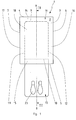
- Fig. 1 shows a slipcover 1 from a plastic film in a flat-lying state.
- the slipcover 1 has a front layer 2 and a in Fig. 1
- the front layer 2 and the backsheet 3 are connected to each other in the region of an upper boundary 4, a lower boundary 5 and the lateral boundaries 6, 7, so that a kind of "closed-off" bag is formed.
- the boundaries 4-7 may be formed by a fold of a film that forms both the front layer 2 and the backsheet 3, and / or in the form of a weld.
- the in Fig. 1 shows a slipcover 1 from a plastic film in a flat-lying state.
- the slipcover 1 has a front layer 2 and a in Fig. 1
- the front layer 2 and the backsheet 3 are connected to each other in the region of an upper boundary 4, a lower boundary 5 and the lateral boundaries 6, 7, so that a kind of "closed-off" bag is formed.
- the boundaries 4-7 may be formed by a fold of
- the "bag” has a rectangular basic geometry with a longitudinal axis 8-8, wherein the longitudinal axis is curved in the assembled state of the protective cover 1 according to the curvature of the vehicle seat and correlated with axes of symmetry of the seat cushion and the backrest of the vehicle seat.
- approximately U-shaped recess 9 is introduced, wherein the U is open in the direction of the lower boundary 5.
- the interior of the U-shaped notch 9 is folded out of the further regions of the reserve 3 around a connection region 10.
- the connecting region 10 is formed as a connecting line, the side legs 11, 12 of the U-shaped recess 9 connects to each other.
- the interior of the incision 9 thus folded over or folded over forms a tongue-like or lobe-like foot region 13.
- the reserve 3 forms an upper pocket region 14, a lower pocket region 15 and lateral connection regions 16, 17
- a seat portion 19 of the protective cover 1 is formed with the entire front layer 2 and the areas 14-17.
- the seating area may be slipped over a motor vehicle seat 20, wherein the upper pocket portion 14 may receive the upper end portion of a seat back 21, while the lower pocket portion 15 may enclose the forward end portion of a seat cushion 22.
- note elements 23 are printed, in which it is for the in Fig. 1 illustrated embodiment is to footsteps.
- the seat portion 19 is formed in the cross-section in the shape of a flattened C, wherein the front layer 2 forms the continuous vertical leg of C, the upper pocket portion 14 forms the upper short flattened leg of the C and the lower pocket portion 15 of the lower flattened leg of the C forms.
- the foot region 13 adjoins the free end region of the lower leg of the C with the connecting region 10 to the seat portion 19 in the form of the flattened C in alignment parallel to the vertical leg of the C and extension of the seat portion 19 away. Between the end portions of the flattened leg part of the C, which are formed by the pocket portions 14, 15, the recess extends 18.
- the lower pocket portion 15 and the foot portion 13 is an S-shaped longitudinal section. For a corresponding longitudinal section with cutting guide through the connecting portions 16, 17, a longitudinal section in the form of a flattened O.
- Fig. 3 shows first the motor vehicle seat 20, which is formed with a backrest 21 and a seat cushion 22, on a corresponding substructure 24, and a footwell 25 with a floor 26.
- the seating area 19 is L-shaped over the motor vehicle seat 20 in side view.
- the front layer 2 abuts the front of the backrest 21 and the top of the seat cushion 22.
- the lateral boundaries 6, 7 are located laterally of the backrest 21 and the seat cushion 22.
- the upper pocket portion 14 encloses the backrest 21 and a headrest 27 thereof, while the lower pocket portion 15 surrounds the front end portion of the seat cushion 22.
- the connection areas 16, 17 of the reserve 2 surround at least partial areas of the side surfaces of the seat cushion 22 and the backrest 21.
- connection area 10 is in this mounted state on the underside of the seat cushion 22, and set back relative to the front end area of the seat cushion 22.
- the foot region 13 forms a connection region 28 and a cover region 29.
- the cover region 29 rests on the floor 26, while the connection region 28 connects the cover region 29 with the connection region 10 and thus with the seat region 19.
- the protective cover 1 is made according to the illustrated embodiment of a gusseted tube, wherein gussets 30, 31 are fixed in the upper boundary, for example, by a the upper boundary 4 forming transverse weld.
- the gussets in the area of the upper limit 4 can not be deployed while this in Fig. 4 to unfold increasingly downwards.
- the seat area 19 can aproximate the shape of the backrest 21 and the headrest 27, wherein the side folds 30, 31 can form a kind of guide or centering with upward decreasing distance during the everting of the seat area 19 on the upper end portion of the backrest 21 with headrest 27 ,
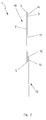
- Fig. 5 shows a web 32 of a continuous flattened plastic tube which is moved in a conveying direction 33 during manufacture.
- protective covers 1a, 1b, 1c by transverse to the conveying direction 33 oriented, continuous perforations 34, 35 separated from each other. Closely adjacent to the perforations 34, 35 are on both sides of the perforations 34, 35 transverse welds 36, 37, with which the upper boundary 4 and the lower boundary 5 of the protective cover 1 is formed.
- Fig. 5 shows a view of the front layer 2 covering the reserve 3 with U-shaped cuts 9, which are introduced in the direction of the conveying direction 33, so the longitudinal axis of the web 32 in the web 32. Folds of the tubular material form the lateral boundaries 6, 7.
- Fig. 6 shows an alternative manufacturing method for a web 32 with protective covers 1 a, 1 b, 1 c.
- the web 32 is formed with a tubular material, but the folds form the upper boundary 4 and the lower boundary 5 as a result of the flattening of the tubular material.
- the individual protective covers 1 a, 1 b, 1 c by perforations 34, 35 separated from each other.
- transverse welds 36, 37 Immediately adjacent to the perforations 34, 35 are transverse welds 36, 37, which in this case form the lateral boundaries 6, 7.
- a here T-shaped recess 9 is introduced with alignment transversely to the conveying direction 33 and longitudinal extent of the web 32 in the reserve 3.
- any other desired cuts 9, for example U, V, T or parabolic cuts 9 can be used.
- a longitudinal axis of the protective cover 1 coincides with the longitudinal extent of the web 32 is for the in Fig. 6 illustrated embodiment, the longitudinal extent of the protective cover 1 transverse to the longitudinal extent of the web 32 oriented.
- a web having a width which is less than the length of the protective cover 1. that is rectangle formed by the flattened protective cover 1 in the FIG. 5 "lying” or arranged in the conveying direction 33, while this according to Fig. 6 "standing” or oriented transversely to the conveying direction 33.
- the incision 9 may also consist of a perforation, or at least remains in spite of the incision 9 in addition to the connecting region 10 a bridge, which is to break through for the folding of the foot area 13.
- the position of the protective cover 1 is designated, which is arranged on the front of the motor vehicle seat 20, ie on the fitter or driver side facing.
- the rear side includes the areas which are arranged on the rear side of the motor vehicle seat 20.
- the depth of the pockets formed - and thus the distance of the connecting portion 10 of the base leg of the U-shaped recess 9 - may be slightly or substantially larger than in the illustrated figures.
- the depth of the upper pocket is up to 1/3 of the length of the seating area.
- the protective cover can also be pulled down as far as possible on the back of the backrest 21, so that the largest possible area of the rear side of the motor vehicle seat 20 is covered. The deeper the bag, the better the protection. It may also be advantageous if at least the upper pocket surrounds the backrest as closely as possible, so that it counteracts slippage of the protective cover 1 along and / or transversely to the longitudinal extent of the backrest.
- the lower pocket may have a smaller depth, so that under certain circumstances, only a front part of the seat cushion 22 or only the front edge of the seat cushion 22 is protected.
- the protective cover 1 should not come too far into contact with the substructure 24 or protrude into this, otherwise there is a risk that the protective cover 1 when moving the vehicle seat 20 during test drives or assembly work jammed in the rails or here tears. It should also be avoided that the protective cover 1 comes into contact with a lubricant for the rails, which can contaminate the motor vehicle seat when removing the protective cover 1.
- the protective cover 1 in particular for the case that the front layer 2 and the reserve 3 are formed with different partial films, is welded on all sides.
- Such a modified production can lead to the advantage that the incision 9 can be easily introduced into the reserve 3 before the connection of the same with the front layer 2 by a knife or a punching tool without the risk of damaging the front layer 2 or additional measures to separate the front and back to protect the front position are to meet.
- a further advantage of such an embodiment is that films with different properties, different surfaces or slip resistance can be used.
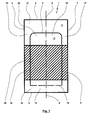
- Fig. 7 shows a further embodiment of the invention, in which the protective cover 1 basically has the same shape and the same recess 9 as in Fig. 1 ,
- Fig. 7 a rear view of the protective cover 1 is shown.
- the front layer 2 is formed with a coextruded film which is smooth on the outer side facing the user during operation, while on the inner side facing the motor vehicle seat it is provided with increased slip resistance.
- the reserve with three longitudinally successive rectangular sections 38, 39, 40 is formed, wherein the central portion 39 in Fig. 7 hatched for clarity.
- the portions 38, 39, 40 are cohesively in the adjoining areas as well as in the transition region to the front layer 2 or connected by welding.
- the sections 38, 40 are formed with a monofilm, which is divided in the manufacturing process.
- This monofilm is formed both inside and outside with a relatively smooth material, whereby an opening of the pocket portions 14, 15 and a detachment of the foot portion 13 is to be simplified.
- the portion 39 is formed with a coextruded film which is slip-proof or adhesive on the inner side while the outer side is smooth. As in Fig. 7 can be seen, the incision extends 9 with the side legs 11, 12 completely through the portion 39 and partially in the sub-areas 38, 40.
- the unfolding of the foot area 13 and the arrangement of the protective cover 1 in the motor vehicle carries the previously described design of different adhesion values or roughnesses of the front layer 2 ensure that the protective cover 1 on the one hand adheres well to the motor vehicle seat 20 and on the other hand the protective cover 1 can slide relative to a user sitting on the motor vehicle seat 20.
- the subregions 38, 40 arranged areas of the foot area 13 can be easily solved here for the assembly of the protective cover 1 in consequence of the smooth inside.
- the non-slip inner side of the foot region 13 can be placed on a doormat or the footer 26, so that the foot region 13 adheres well to the floor 26.
- the smooth inner side of the foot region 13 in the partial region 39 can serve as a support surface for the feet of the user, so that the feet can easily slide over the foot region 13, without this necessarily leading to an undesired displacement of the foot region 13.
- a one-piece construction of the protective cover 1 is understood in particular to mean a production of the protective cover from a single continuous film or from several film pieces connected or welded together in a materially bonded manner.
- the design as “smooth” or “rough” can be achieved by using a monofilm, a coextruded film with specifically selected different materials for the individual layers of the coextruded film.
- Adhesive layers can also be provided, via which a specific adhesion can be brought about.
- the lubricant proportions for different layers can be varied in a targeted manner. It is possible that a coefficient of friction for a strongly adhering portion is formed to be about 1.0 or greater than 1.0, while in areas designated as smooth, the coefficient of friction, for example, is only about 0.1 or only 0.01.
- the coefficient of friction may vary between about 0.05 and 0.1.
- a coefficient of friction of about 0.2 to 0.8 can be formed on one side, while on the other side a coefficient of friction of about 0.1 to 0.2 is given.
- a determination of said coefficient of friction can be done, for example, based on DIN 53375.
- the basic idea of the present invention can be implemented as a semi-tool both for the use of a hose, a half hose, each with or without gussets, as well as at least two flat films, which are connected to each other, for example via welding.
- the protective cover 1 can be used for a front seat, so that the width of the protective cover 1 corresponds approximately to the width of the front seat. Also possible is the use of a protective cover according to the invention for a kind of seat, which can also form rear seats or a back seat of the motor vehicle. Here, the protective cover can extend over approximately the entire width of the car with a continuous, "fold-out" doormat. This is of particular interest for vans, minibuses or similar vehicles, in which the footwell in the area of a bank or a rear seat is formed continuously without, for example, a transmission tunnel runs here. Also possible is a reduced width in the case where the back seat is divided into 1/3 and 2/3, for example.
- the entire material of the reserve for the seating area on the one hand and the foot area on the other hand need not be used. Rather, it is also possible that subareas are used for other tasks or separated out as unused parts.
Abstract
Description
Die Erfindung betrifft einen Schutzbezug für ein Kraftfahrzeug, der einen Sitzbereich aufweist, welcher zur zumindest teilweisen Abdeckung eines Kraftfahrzeugsitzes des Kraftfahrzeuges dient. Weiterhin betrifft die Erfindung eine Bahn mit derartigen Schutzbezügen.The invention relates to a protective cover for a motor vehicle, which has a seating area which serves for the at least partial covering of a motor vehicle seat of the motor vehicle. Furthermore, the invention relates to a web with such protective covers.
Schutzbezüge der hier vorliegenden Art dienen dem Schutz des Innenraumes eines Kraftfahrzeuges gegenüber Verschmutzungen. Beispielsweise findet ein derartiger Schutzbezug Einsatz zum Schutz eines Kraftfahrzeugsitzes vor einer Erstauslieferung eines Kraftfahrzeuges an einen Kunden. Ebenfalls möglich ist der Einsatz des Schutzbezuges, wenn sich das Kraftfahrzeug in einer Werkstatt befindet. In beiden Fällen besteht die Gefahr, dass sich ein Monteur mit verunreinigter Kleidung auf den Kraftfahrzeugsitz setzt. Ist in einem derartigen Fall zwischen Monteur und Kraftfahrzeugsitz ein Schutzbezug eingeordnet, wird der Kraftfahrzeugsitz geschützt und allenfalls der Schutzbezug verunreinigt, der anschließend entfernt werden kann. Bei dem gattungsgemäßen Schutzbezug kann es sich um einen Einmal-Schutzbezug oder einen Schutzbezug für einen mehrmaligen Einsatz handeln.Protective covers of the present type are used to protect the interior of a motor vehicle against contamination. For example, such a protective cover is used to protect a motor vehicle seat from an initial delivery of a motor vehicle to a customer. Also possible is the use of the protective cover when the vehicle is in a workshop. In both cases, there is a risk that a mechanic with contaminated clothing sits on the vehicle seat. If, in such a case, a protective cover is arranged between the mechanic and the motor vehicle seat, the motor vehicle seat is protected and at most the protective cover is contaminated, which can then be removed. The generic protective cover may be a disposable protective cover or a protective cover for repeated use.
Weiterhin kann der Schutzbezug eingesetzt werden bei dem Hersteller des Kraftfahrzeugsitzes und bei der Zulieferung des Kraftfahrzeugsitzes zu einem Automobilwerk oder einer Werkstatt. Vorteilhaft kann auch der Einsatz des Schutzbezuges bei der Bestückung von Förderanlagen sein. Schließlich muss in dem Automobilwerk das fertig gestellte Kraftfahrzeug von einem Band gefahren werden, in eine Auslieferungshalle verbracht werden, auf einen Lastkraftwagen oder Eisenbahnwaggon oder ein Schiff geladen werden und letztendlich bei einem Kraftfahrzeughändler nochmals gehandhabt werden, bis das Kraftfahrzeug letztendlich in die Hand des Erwerbers ausgeliefert werden kann. Von der Herstellung des Sitzes beim Zulieferer bis zur Auslieferung des Kraftfahrzeuges an den Erwerber kommen die Kraftfahrzeug-Sitze etwas 30 bis 35 mal in Kontakt mit Monteuren und mit anderen Personen, so dass viele Möglichkeiten für eine Verschmutzung des Kraftfahrzeugsitzes bestehen, die mit gattungsgemäßen Schutzbezügen vermieden werden sollen.Furthermore, the protective cover can be used by the manufacturer of the motor vehicle seat and by the delivery of the motor vehicle seat to an automobile plant or a workshop. Also advantageous may be the use of the protective cover in the assembly of conveyor systems. Finally, in the automobile plant, the finished motor vehicle must be driven off a conveyor belt, taken to a delivery hall, onto a truck or Railway wagon or a ship are loaded and ultimately be handled again at a motor vehicle dealer until the motor vehicle can ultimately be delivered in the hands of the purchaser. From the production of the seat at the supplier to the delivery of the motor vehicle to the purchaser, the motor vehicle seats come some 30 to 35 times in contact with fitters and other people, so that many possibilities for contamination of the vehicle seat exist that avoided with generic protective covers should be.
Ein erster Schutzbezug ist aus
Auch in
Aus
Weiterer Stand der Technik ist aus
Übliche Anforderungen an gattungsgemäße Schutzbezüge sind
- eine einfache Handhabbarkeit derselben,
- ein geringer Preis,
- eine einfache Lagerbarkeit, Transportierbarkeit und Bereitstellungsmöglichkeit derselben,
- deren einfache und u. U. umweltverträgliche Entsorgung,
- deren Haltbarkeit im Einsatz,
- deren zuverlässige Anbindung an den Kraftfahrzeugsitz
- und Ähnliches.
- easy handling of the same,
- a low price,
- a simple storability, transportability and provision possibility of the same,
- whose simple and u. U. environmentally sound disposal,
- their durability in use,
- their reliable connection to the vehicle seat
- and similar.
Der vorliegenden Erfindung liegt die Aufgabe zugrunde, einen Schutzbezug, wie dieser beispielsweise aus dem Stand der Technik bekannt ist, und eine Bahn mit mehreren Schutzbezügen durch alternative oder kumulative Maßnahmen weiterzubilden, insbesondere derart, dass
- eine verbesserte Schutzwirkung des Schutzbezuges,
- eine einfache Handhabbarkeit für den Benutzer des Schutzbezuges,
- eine gute Sicherung von Teilen des Schutzbezuges gegenüber unerwünschten Bewegungen relativ zum Kraftfahrzeugsitz und/oder
- eine vereinfachte Abgabe und Bereitstellung eines Schutzbezuges an den Benutzer
- an improved protective effect of the protective cover,
- easy handling for the user of the protective cover,
- a good assurance of parts of the protective cover against unwanted movements relative to the motor vehicle seat and / or
- a simplified delivery and provision of a protective cover to the user
Die Aufgabe der Erfindung wird erfindungsgemäß mit einem Schutzbezug gemäß den Merkmalen des unabhängigen Patentanspruchs 1 gelöst. Weitere Ausgestaltungen eines erfindungsgemäßen Schutzbezuges ergeben sich entsprechend den abhängigen Patentansprüchen 2 bis 17. Eine weitere Lösung der der Erfindung zugrunde liegenden Aufgabe stellt eine Bahn mit den Merkmalen des Patentanspruchs 18 dar. Weitere Ausgestaltungen einer erfindungsgemäßen Bahn mit mehreren Schutzbezügen sind in den abhängigen Patentansprüchen 19 bis 22 definiert.The object of the invention is achieved with a protective cover according to the features of
Die vorliegende Erfindung ist geeignet, für einen beliebigen Schutzbezug eingesetzt zu werden, der beispielsweise entsprechend dem eingangs erläuterten Stand der Technik ausgebildet sein kann oder abweichend hierzu und für einen einmaligen oder mehrfachen Gebrauch bestimmt und hergerichtet sein kann.The present invention is suitable for use with any protective cover which may, for example, be constructed in accordance with the prior art described in the opening paragraph or may be deviating from this and intended and prepared for a single or multiple use.
Bisher ist die Fachwelt vorrangig dem Vorurteil gefolgt, dass ein gattungsgemäßer Schutzbezug lediglich einem Abdecken eines Kraftfahrzeugsitzes dienen kann. Soll zusätzlich zu einem Schutz des Kraftfahrzeugsitzes gewährleistet werden, dass ein Fußraum des Kraftfahrzeuges ebenfalls vor Verunreinigungen geschützt werden soll, beispielsweise vor Partikeln oder Verschmutzungen, beispielsweise Öl, die sich an der Sohle eines Schuhs eines Fahrers oder Monteurs abgelagert haben, wurde hierzu eine separate Fußraum-Abdeckung eingesetzt. Dieses erfordert bereits bei der Herstellung u. U. die separate Herstellung des Schutzbezuges einerseits und der Fußraum-Abdeckung andererseits. Auch hat eine separate Verpackung, ein separater Transport und eine separate Bereitstellung zu erfolgen. Weiterhin hat auch der Benutzer zwei separate Teile, nämlich einerseits den Schutzbezug und andererseits die Fußraum-Abdeckung, nacheinander in dem Kraftfahrzeug anzuordnen, weshalb zunächst der Schutzbezug für den Kraftfahrzeugsitz von einem Ablageort zu holen ist und mit dem Kraftfahrzeugsitz zu verbinden ist. Dann muss die Fußraum-Abdeckung von einem weiteren Ablageort geholt werden und anschließend in dem Fußraum angeordnet werden.So far, the experts have primarily followed the prejudice that a generic protective cover can only serve to cover a motor vehicle seat. If, in addition to a protection of the motor vehicle seat, it is to be ensured that a footwell of the motor vehicle is also to be protected from contamination, for example from particles or soiling, for example oil, which have deposited on the sole of a driver's or mechanic's shoe, a separate footwell was used for this purpose Cover used. This requires already in the production u. U. the separate production of the protective cover on the one hand and the footwell cover on the other. Also, a separate packaging, a separate transport and a separate provision must be made. Furthermore, the user has two separate parts, namely on the one hand the protective cover and on the other hand, the footwell cover to arrange one after the other in the vehicle, which is why first the protective cover for the motor vehicle seat is to get from a storage location and connect to the vehicle seat. Then the footwell cover must be fetched from another storage location and then placed in the footwell.
Die vorliegende Erfindung beschreitet den Weg, einen Schutzbezug vorzuschlagen, welcher sowohl einen Sitzbereich aufweist, der der zumindest teilweisen Abdeckung eines Kraftfahrzeugsitzes des Kraftfahrzeuges dient, als auch einen Fußbereich, der der zumindest teilweisen Abdeckung eines Fußraumes des Kraftfahrzeuges dient. Hierbei ist der Fußbereich mit dem Sitzbereich verbunden.The present invention is based on the way to propose a protective cover, which has both a seating area, the at least partial coverage of a Motor vehicle seat of the motor vehicle is used, as well as a foot area, which serves the at least partial coverage of a footwell of the motor vehicle. Here, the foot area is connected to the seating area.
Selbstverständlich kann der Schutzbezug nicht nur in dem Kraftfahrzeug Einsatz finden, wo der Fußbereich der Abdeckung des Fußraumes dient. Vielmehr kann der Schutzbezug auch beispielsweise während eines Transportes des Kraftfahrzeugsitzes Einsatz finden, wo der Fußbereich ohne Funktion ist. In diesem Fall kann der Fußbereich gelöst oder abgerissen werden, was insbesondere über Perforationen des Übergangsbereiches vom Fußbereich zum Sitzbereich vorbereitet sein kann, oder ohne weitere Funktion mit dem Sitzbereich verbunden bleiben und beispielsweise zurückgebunden oder zurückgefaltet werden oder über einen Klebestreifen an einem anderen Teil befestigt werden. In alternativer Ausgestaltung kann bei einem Transport vom Sitzhersteller zur Montagelinie der Kraftfahrzeugsitz durch den Schutzbezug geschützt werden. Nach der Montage des Kraftfahrzeugsitzes im Fahrzeug wird der Fußbereich nachträglich ausgeklappt und dient dann dem Schutz des Fußraumes.Of course, the protective cover can not only find use in the motor vehicle, where the foot area of the cover of the footwell is used. Rather, the protective cover can also be used, for example, during transport of the motor vehicle seat, where the foot area is without function. In this case, the foot area can be loosened or torn off, which in particular can be prepared via perforations of the transition area from the foot area to the seating area, or remain connected to the seating area without further function and for example tied back or folded back or attached to another part via an adhesive strip , In an alternative embodiment, the motor vehicle seat can be protected by the protective cover in a transport from the seat manufacturer to the assembly line. After mounting the vehicle seat in the vehicle, the foot area is subsequently unfolded and then serves to protect the footwell.
Die erfindungsgemäße Ausgestaltung führt auf die folgenden alternativen oder kumulativen Vorteile:
- Für die separate Ausbildung von Sitzbereich und Fußbereich verbleibt u. U. eine Stirnfläche des Sitzpolsters oder eine Stirnseite des Unterbaus des Sitzpolsters ohne Abdeckung, so dass hier keine Schutzfunktion gewährleistet ist. Schlimmstenfalls kann es passieren, dass Werkzeug, Schrauben oder Ähnliches unbeabsichtigt in einen Hohlraum unter den Sitz eintreten oder eine Verschmutzung stirnseitiger Bereiche des Unterbaus auftritt. Erfindungsgemäß kann auch in diesem stirnseitigen Bereich eine zusätzliche Abdeckung geschaffen werden, wodurch die Schutzfunktion des Schutzbezuges erweitert ist.
- Für die separate Ausbildung von Sitzbereich und Fußbereich ist die relative Lage zwischen Sitzbereich und Fußbereich beliebig, was beispielsweise dazu führen kann, dass ein Fahrer des Kraftfahrzeuges für mehrmals bewegten Fuß, beispielsweise bei einer Betätigung der Pedale des Kraftfahrzeuges, den Fußbereich in den vorderen Endbereich des Fußraumes verschiebt, wo die Fußraum-Abdeckung ihre Funktion nicht erfüllen kann. Schlimmstenfalls kann die zusammengeschobene Fußraum-Abdeckung die Betätigung der Pedale des Kraftfahrzeuges beeinträchtigen, was ein Sicherheitsrisiko für das unter Umständen neuwertige Kraftfahrzeug darstellt. Durch die erfindungsgemäße Verbindung von Fußbereich und Sitzbereich ist die Verschiebemöglichkeit des Fußbereiches gegenüber dem Sitzbereich in Richtung der Fahrzeuglängsachse nach vorne begrenzt, wodurch die genannten Probleme beseitig oder gemindert sind.
- Für die separate Ausbildung von Sitzbereich und Fußbereich ist die Zahl der Montageschritte für den Benutzer oder Monteur erhöht. Da der Einsatz eines Schutzbezuges von dem Monteur unter Umständen als ein lästiger Zusatzschritt angesehen wird, der dem eigentlichen angestrebten Arbeitsergebnis des Monteurs aber nicht förderlich ist, ist die Gefahr gegeben, dass der Monteur auf die Anordnung der Fußraum-Abdeckung für die separate Ausbildung derselben verzichtet. Ein derartiges Fehlverhalten des Monteurs kann erfindungsgemäß vermieden werden, da die Fußraum-Abdeckung in Form des Fußbereiches nach der Montage des Sitzbereiches des Schutzbezuges an dem Kraftfahrzeugsitz ohnehin vorhanden ist, und zwar bereits ohne ergänzende Montageschritte, bspw. durch ein schnelles Ausfalten und/oder Glattstreichen des Fußbereiches.
- Gleiches gilt für eine Entfernung des Schutzbezuges aus dem Kraftfahrzeug, welche für die erfindungsgemäße Ausgestaltung - im Gegensatz zu der separaten Ausbildung von Fußraum-Abdeckung und Sitzbereich - lediglich einen Entnahmeschritt bedingt.
- Auch besteht potentiell die Gefahr, dass eine Fußraum-Abdeckung an dem Schuh eines Monteurs anhaftet, beispielsweise durch einen spitzen Gegenstand in der Sohle des Schuhs des Monteurs oder ein adhäsives Mittel an der Sohle des Monteurs. Verlässt der Monteur das Fahrzeug, muss der Monteur die ungewollte Entnahme der Fußraum-Abdeckung aus dem Fußraum dadurch vermeiden, dass er sich bückt und die Fußraum-Abdeckung von der Sohle abstreift. Dieses kann unter Umständen erfindungsgemäß vermieden werden, da eine Entnahme des Fußbereiches durch die Verbindung desselben mit dem Sitzbereich erschwert ist.
- For the separate training of seating area and foot area u. U. an end face of the seat cushion or an end face of the base of the seat cushion without cover, so that no protective function is guaranteed here. In the worst case, it can happen that tools, screws or the like inadvertently enter a cavity under the seat or contamination of the frontal areas of the substructure occurs. According to the invention, an additional cover can be created in this frontal area, whereby the protective function of the protective cover is extended.
- For the separate formation of the seating area and foot area, the relative position between the seat area and foot area is arbitrary, which may, for example, lead a driver of the motor vehicle to move the foot area into the front end area of the motor vehicle for several times, eg when operating the pedals of the motor vehicle Footwell moves where the footwell cover can not fulfill its function. In the worst case, the collapsed footwell cover may interfere with the operation of the pedals of the motor vehicle, which may pose a safety risk represents as new motor vehicle. Due to the inventive connection of the foot area and the seating area, the possibility of displacement of the foot area relative to the seat area in the direction of the vehicle longitudinal axis is limited forwards, as a result of which the stated problems are eliminated or reduced.
- For the separate training of seating area and foot area, the number of assembly steps for the user or fitter is increased. Since the use of a protective cover is considered by the fitter under certain circumstances as a troublesome additional step, which is not conducive to the actual desired work result of the fitter, the danger is that the fitter dispenses with the arrangement of the footwell cover for the separate training of the same , Such a malfunction of the mechanic can be avoided according to the invention, since the footwell cover in the form of the foot area after installation of the seating area of the protective cover on the motor vehicle seat is already present, even without additional assembly steps, eg. By rapid unfolding and / or smoothing of the foot area.
- The same applies to a removal of the protective cover from the motor vehicle, which for the inventive design - in contrast to the separate formation of footwell cover and seating area - only one sampling step.
- Also, there is a potential danger that a footwell cover will adhere to the shoe of a mechanic, for example, by a sharp object in the sole of the mechanic's shoe or an adhesive agent on the mechanic's sole. If the fitter leaves the vehicle, the installer must avoid accidentally removing the footwell cover from the footwell by bending over and scraping the footwell cover off the sole. Under certain circumstances, this can be avoided according to the invention, since removal of the foot region is made more difficult by its connection to the seating area.
Gemäß der Erfindung ist der Schutzbezug mit einer Vorderlage und einer Rücklage gebildet. Der Fußbereich bildet hierbei einen Teilausschnitt aus der Rücklage. Von besonderem Vorteil ist hierbei, wenn der Fußbereich aus der Rücklage derart ausgeklappt wird, dass die der Vorderlage zugewandte Oberfläche der Rücklage einerseits die Anlagefläche der Rücklage an den Kraftfahrzeugsitz bildet und andererseits eine Unterseite des Fußbereiches für Anordnung desselben in dem Fußraum bildet. Damit kann gewährleistet werden, dass die genannte Oberfläche sowohl für den Sitzbereich als auch für den Fußbereich eine Kontaktfläche zu den geschützten Bereichen, nämlich einerseits den Kraftfahrzeugsitz und andererseits den Fußraum, bildet, so dass für diese Oberflächen für Sitzbereich und Fußbereich vergleichbare Anforderungen gelten. Beispielsweise kann diese Oberfläche mit einer hohen Rauhigkeit versehen werden, um Relativbewegungen zwischen Rücklage und Kraftfahrzeugsitz sowie Fußraum zu vermeiden. Gleiches gilt für die andere Oberfläche der Rücklage, die damit einerseits von dem Benutzer im Bereich des Kraftfahrzeugsitzes zugänglich ist und insbesondere reibungsarm gestaltet sein kann und andererseits von den Füßen des Benutzers im Bereich des Fußraumes zugänglich ist.According to the invention, the protective cover is formed with a front layer and a backsheet. The foot area here forms a partial section of the reserve. Of particular advantage here is when the foot area is folded out of the reserve such that the front layer facing surface of the reserve on the one hand forms the contact surface of the reserve to the vehicle seat and on the other hand, a bottom of the foot area for arrangement the same forms in the footwell. This can be ensured that the said surface for both the seating area and the foot area a contact surface to the protected areas, namely on the one hand the vehicle seat and on the other hand, the footwell forms, so that apply to these surfaces for seating area and foot area comparable requirements. For example, this surface can be provided with a high degree of roughness in order to avoid relative movements between the reserve and the motor vehicle seat as well as the foot space. The same applies to the other surface of the reserve, which is thus accessible on the one hand by the user in the area of the motor vehicle seat and in particular can be designed low friction and on the other hand is accessible from the feet of the user in the footwell.
Während gemäß dem Stand der Technik als Fußraum-Abdeckung vorrangig Papier oder einen Karton Einsatz findet, wird erfindungsgemäß der Einsatz beliebiger Materialien, insbesondere eine Folie, als eine Fußraumabdeckung in Betracht gezogen.While according to the prior art paper or cardboard is used primarily as a footwell cover, according to the invention the use of any materials, in particular a film, is considered as a footwell cover.
Während grundsätzlich eine separate Ausbildung von Fußbereich und Sitzbereich möglich ist, wobei dann eine Verbindung von Fußbereich und Sitzbereich über geeignete Verbindungselemente, beispielsweise Klebestreifen, Klettverbindungen, Verbindungsstreifen, die miteinander verknotet werden, und Ähnliches erfolgt, ist vorzugsweise der Sitzbereich einstückig mit dem Fußbereich ausgebildet, wobei hierunter auch eine Herstellung von Sitzbereich und Fußbereich aus einem einzigen durchgehenden Material oder einer Kunststofffolie verstanden wird oder die separate Fertigung von Sitzbereich und Fußbereich mit anschließender stoffschlüssiger Verbindung, beispielsweise über eine Schweißverbindung oder ein adhäsives Mittel.While in principle a separate formation of foot area and seating area is possible, wherein a connection of the foot area and the seating area via suitable connecting elements, for example adhesive strips, Velcro connections, connecting strips which are knotted together, and the like, preferably the seating area is formed integrally with the foot area, this is also understood to mean the production of a seating area and foot area from a single continuous material or a plastic film, or the separate production of the seating area and foot area with a subsequent material connection, for example via a welded connection or an adhesive agent.
Eine besonders einfache Fertigung ergibt sich für den erfindungsgemäßen Schutzbezug, wenn der Sitzbereich und der Fußbereich aus einer einzigen Folie hergestellt sind. Hierbei besitzt die Folie einen Einschnitt, der über mindestens ein geeignetes Schneidelement mechanisch oder thermisch in die Folie eingebracht sein kann. Dieser einfach herzustellende Einschnitt erfüllt zwei Funktionen:
- Einerseits begrenzt der Einschnitt den Fußbereich, so dass aus der Folie mit Einbringen des Einschnittes der Fußbereich herausgetrennt werden kann, der dann beispielsweise vor einer Verpackung oder nach Entnahme des Schutzbezuges abgeklappt oder abgefaltet wird, so dass sich dieser in dem Kraftfahrzeug vor dem Sitzbereich erstreckt.
- Andererseits wird durch den Einschnitt eine Ausnehmung des Sitzbereiches begrenzt, bei der es sich vorzugsweise um die Ausnehmung aus der Rücklage des Sitzbereiches handelt, welche rückseitig die mindestens eine Tasche begrenzt und/oder seitliche Verbindungsstreifen begrenzt, die seitlich den Kraftfahrzeugsitz umschließen können. Mit dem Abklappen des Fußbereiches wird die Ausnehmung freigelegt, die dann dazu dienen kann, den Sitzbereich mit einer oder zwei Taschen und/oder Seitenstreifen über den Kraftfahrzeugsitz zu stülpen. Bei der "einzigen Folie" kann es sich selbstverständlich auch um einer coextrudierte Folie handeln, die mehrere Schichten besitzt. Der Einschnitt kann als durchgehender Schnitt, beispielsweise mit einem oder mehreren Messern, eingebracht werden oder über mehrere Teilschnitte oder mindestens einer Perforation. Alternativ zu dem mindestens einen genannten Messer kann ein Stanzwerkzeug Einsatz finden. Von der Formulierung "einzige Folie" auch umfasst sein sollen Ausführungsformen, bei denen der Fußbereich und der Sitzbereich im Wesentlichen aus dieser Folie hergestellt sind, aber ergänzende Elemente für zusätzliche Taschen, Befestigungselemente und Ähnliches unter Umständen aus weiteren Folien oder anderen Materialien hergestellt sind.
- On the one hand, the incision limits the foot area, so that the foot area can be cut out of the film with the introduction of the incision, which then, for example, before a Packing or folded after removal of the protective cover or folded so that it extends in the motor vehicle in front of the seating area.
- On the other hand, a recess of the seating area is limited by the incision, which is preferably the recess from the reserve of the seating area, which at the back limits the at least one pocket and / or limits lateral connecting strips which can laterally enclose the motor vehicle seat. With the folding down of the foot area, the recess is exposed, which can then serve to put the seating area with one or two pockets and / or side strips over the vehicle seat. Of course, the "single film" may also be a coextruded film having multiple layers. The incision may be introduced as a continuous cut, for example with one or more knives, or over several partial cuts or at least one perforation. As an alternative to the at least one mentioned knife, a punching tool can be used. Also to be encompassed by the term "sole film" are embodiments in which the foot region and the seating area are essentially made of this film, but complementary elements for additional pockets, fasteners and the like may be made from other films or other materials.
In den aus dem Stand der Technik bekannten Lösungen besteht die Fußraum-Abdeckung aus einem anderen Material als der Sitzsschutz. Bei der Entsorgung ist ein sortenreines Recycling deshalb nur bedingt oder mit erhöhtem Aufwand möglich, wobei u. U. getrennte Entsorgungswege für die Fußraum-Abdeckung einerseits und den Schutzbezug andererseits vorzusehen sind. Hier schafft die erfindungsgemäß Ausgestaltung mit der einstückigen Ausbildung, bei der sowohl Fußbereich als auch Sitzbereich mit einer Folie gebildet sind, Vereinfachung.In the solutions known from the prior art, the footwell cover is made of a different material than the seat protection. When disposing of a sorted recycling is therefore possible only conditionally or with increased effort, with u. U. separate disposal routes for the footwell cover on the one hand and the protective cover on the other hand are provided. Here, the embodiment according to the invention with the one-piece design, in which both the foot area and the seat area are formed with a film, simplifies.
Eine entsprechend einer Weiterbildung des erfindungsgemäßen Schutzbezuges in erster Näherung U-förmige, V-förmige, T-förmige oder parabelförmige Ausbildung des Einschnittes kann auf einfache Weise gefertigt werden. Andererseits stellen U-förmige, V-förmige, T-förmige oder parabelförmige Einschnitte geeignete Ausnehmungen für den Sitzbereich bereit für eine einfache Montierbarkeit und zuverlässige Verbindung zwischen Sitzbereich und Kraftfahrzeugsitz. Gleichzeitig wird durch derartige Einschnitte ein Fußbereich begrenzt, der den Gegebenheiten im Fußraum und von den Füßen beaufschlagten Teilbereichen desselben Rechnung trägt. Unter einer U-Form wird in diesem Zusammenhang eine Form verstanden, bei welcher zwei ungefähr parallele Seitenschenkel vorhanden sind, die über einen geradlinigen oder beliebig gekrümmten Verbindungsbereich miteinander verbunden sind. Durchaus möglich ist, dass auch die Seitenschenkel des U nicht geradlinig ausgebildet sind, sondern beliebig kurvenförmig. Im Gegensatz hierzu wird unter einer V-Form eine Ausbildung mit spitz zulaufenden Seitenschenkeln verstanden, die geradlinig oder kurvenförmig ausgebildet sein können, wobei der Verbindungsbereich der Seitenschenkel spitz oder abgerundet ausgebildet sein kann. Unter einer T-Form wird eine Hammer-Form verstanden, bei welcher der Einschnitt beidseits des Vertikalschenkels des T bzw. des Hammerstieles verläuft sowie um den Querschenkel des T bzw. den Hammerkopf. Der Querschenkel des T kann dann für den Fußbereich eine verbreiterte Aufstandsfläche für den Fuß und Schutzfläche in dem Fußraum bereitstellen, während der Vertikalschenkel des T vorrangig der Anbindung des Querschenkels an den Sitzbereich dienen kann. Eine Ausgestaltung der gewählten Kurvenformen kann abhängen von der Art der Einbringung des Einschnittes: Während quer zu einer Förderrichtung des Schutzbezuges während der Herstellung orientierte Teilbereiche des Einschnittes eher eine Taktförderung erfordern, bei der dann ein "Einstanzen" des Einschnittes oder ein zeitlich andauerndes Einschneiden des Einschnittes erfolgt, können gegenüber der Querrichtung geneigte Einschnitte beliebiger Form auch während einer kontinuierlichen Förderung des Schutzbezuges unter Einsatz eines temporär in den Schutzbezug eintauchenden Schneidelementes erzeugt werden. Hierbei kann das Schneidelement durch die Förderbewegung des Schutzbezuges relativ zu diesem bewegt und ergänzend in Querrichtung bewegt werden.A corresponding to a development of the protective cover according to the invention in a first approximation U-shaped, V-shaped, T-shaped or parabolic-shaped formation of the incision can be made in a simple manner. On the other hand, U-shaped, V-shaped, T-shaped or parabolic cuts provide suitable recesses for the seating area for easy assembly and reliable connection between the seating area and the motor vehicle seat. At the same time a foot area is limited by such cuts, which takes into account the conditions in the footwell and acted upon by the feet of the same areas. Under a U-shape is understood in this context, a form at which two approximately parallel side legs are present, which are connected to each other via a straight or arbitrarily curved connection area. It is quite possible that the side legs of the U are not rectilinear, but arbitrarily curved. In contrast, a V-shape is understood to mean an embodiment with tapering side limbs, which can be rectilinear or curve-shaped, wherein the connecting region of the side limbs can be pointed or rounded. A T-shape is understood to mean a hammer shape in which the incision extends on both sides of the vertical limb of the T or the hammer stem and about the transverse limb of the T or the hammer head. The transverse leg of the T can then provide for the foot area a widened footprint for the foot and protective surface in the footwell, while the vertical leg of the T can serve primarily the attachment of the transverse leg to the seat area. An embodiment of the selected waveforms may depend on the nature of the introduction of the incision: While transverse to a conveying direction of the protective cover during manufacture oriented portions of the incision require more a Taktförderung, in which then a "punching" of the incision or a time-consuming incision of the incision takes place, relative to the transverse direction inclined incisions of any shape can also be generated during a continuous promotion of the protective cover using a temporarily immersed in the protective cover cutting element. Here, the cutting element can be moved by the conveying movement of the protective cover relative to this and additionally moved in the transverse direction.
Von weiterem Vorteil kann es sein, wenn Lagen des Schutzbezuges mit unterschiedlichen Materialien, Zusammensetzungen, Additiven, Beschichtungen, mechanischen Eigenschaften wie Elastizitäten und Festigkeiten, Reibwerten und/oder Rauhigkeiten gebildet sind. Hierdurch kann gezielt das Verhalten des Schutzbezuges sowohl für den Fußbereich als auch für den Sitzbereich gestaltet werden.It may be of further advantage if layers of the protective cover are formed with different materials, compositions, additives, coatings, mechanical properties such as elasticities and strengths, coefficients of friction and / or roughnesses. In this way, the behavior of the protective cover can be designed specifically for both the foot and the seating area.
Entsprechend einem weiteren erfindungsgemäßen Vorschlag ist ein Verbindungsbereich zwischen Fußbereich und Sitzbereich, welcher beispielsweise durch eine Abknickstelle zwischen Fußbereich und Sitzbereich repräsentiert sein kann, nicht in dem Übergangsbereich von der Vorderlage zu der Rücklage angeordnet, beispielsweise im Bereich einer Faltung zwischen diesen oder einer Verschweißung zwischen diesen, sondern beabstandet von diesem Übergangsbereich angeordnet. Das zwischen Verbindungsbereich und Übergangsbereich angeordnete Material kann zur Bildung einer Tasche genutzt werden. Andererseits wird unter Umständen mittels einer derartigen Tasche der Verbindungsbereich unter dem Sitzpolster etwas zurückgeführt, so dass der Fußbereich hier unmittelbar an einen Unterbau des Kraftfahrzeugsitzes herangeführt werden kann und weniger sichtbar wird. Vorzugsweise beträgt der Abstand zwischen Verbindungsbereich und Übergangsbereich zwischen 5 und 40 cm oder 10 und 25 cm.According to a further inventive proposal, a connection region between the foot region and the seating area, which may be represented for example by a bending point between the foot region and the seating area, is not arranged in the transition region from the front layer to the back layer, for example in the region of a fold between these or a weld between them but spaced from this transition region. That between connection area and transition area arranged material can be used to form a bag. On the other hand, under certain circumstances, the connection region under the seat cushion is somewhat reduced by means of such a pocket, so that the foot region can be brought directly here to a substructure of the motor vehicle seat and becomes less visible. The distance between connection region and transition region is preferably between 5 and 40 cm or 10 and 25 cm.
Eine besonders einfache Fertigung des Schutzbezuges ergibt sich dann, wenn dieser aus einem schlauchartigen Material gefertigt ist, wobei beispielsweise ein einfacher Schlauch oder ein Seitenfaltenschlauch Einsatz finden kann, welcher als Vollschlauch oder Halbschlauch für den Schutzbezug verwendet werden kann. Erfindungsgemäß bildet das schlauchartige Material mit dessen Abplattung die Vorderlage und Rücklage, wobei die genannten Lagen in einem oberen Endbereich sowie in einem unteren Endbereich über Querschweißungen miteinander verbunden sind. Die Querschweißungen verbinden die Lagen miteinander. Bereits hierdurch ist für die Verwendung eines Vollschlauches unter Umständen ein allseits geschlossener "Sack" gebildet, der durch Einbringung des Einschnittes wieder geöffnet wird. Im Fall des Einsatzes eines Halbschlauches kann eine ergänzende Längsschweißung erforderlich sein, um den allseits geschlossenen "Sack" zu bilden. Der Einsatz eines Seitenfaltenschlauches kann vorteilhaft genutzt werden, um eine Art "Taillierung" des Schutzbezuges herbeizuführen, indem in Teilbereichen des Schutzbezuges, insbesondere im Bereich einer Kopfstütze, die Seitenfalten zumindest bereichsweise durch eine Verschweißung festgesetzt sind, während in anderen Teilbereichen ein vergrößerter Querschnitt des Schlauches durch die geöffneten Seitenfalten zu nutzen. Ein derart "taillierter" Schutzbezug passt sich besser an einen Kraftfahrzeugsitz an und kann beispielsweise eine gegenüber dem Kraftfahrzeug verringerte Erstreckung einer Kopfstütze berücksichtigen. Gleichzeitig kann die Taillierung die ordnungsgemäße und exakte Montage des Schutzbezuges auf dem Kraftfahrzeugsitz vereinfachen. Vorzugsweise entsteht die Taillierung im Bereich einer unteren und/oder oberen Querschweißung, wobei die obere Querschweißung der Taillierung des oberen Endbereichs und damit der Rückenlehne und der Kopfstütze zugeordnet ist, während die Taillierung im Bereich der unteren Querschweißung einer Taillierung im Bereich der Vorderseite des Sitzpolsters dient.A particularly simple production of the protective cover is obtained when this is made of a tubular material, for example, a simple hose or gusseted hose can be used, which can be used as a full hose or half hose for the protective cover. According to the invention forms the tubular material with its flattening the front and back position, said layers are connected to each other in an upper end region and in a lower end region via transverse welds. The transverse welds connect the layers with each other. Already hereby, for the use of a full hose under certain circumstances, a "sack" that is closed on all sides is formed, which is opened again by introducing the incision. In the case of the use of a half-hose, a supplementary longitudinal welding may be required to form the "sack" which is closed on all sides. The use of a gusseted tube can be advantageously used to bring about a kind of "waisting" of the protective cover by the gussets are at least partially fixed by welding in partial areas of the protective cover, in particular in the region of a headrest, while in other areas an enlarged cross-section of the hose through the open gussets to use. Such a "waisted" protective cover adapts better to a motor vehicle seat and, for example, can take into account a reduced extension of a headrest relative to the motor vehicle. At the same time, the sidecut can facilitate the proper and accurate mounting of the protective cover on the vehicle seat. Preferably, the waisting in the region of a lower and / or upper transverse weld, the upper transverse weld of the waist of the upper end portion and thus the backrest and the headrest is assigned, while the waisting in the region of the lower transverse weld a waisting in the front of the seat cushion is used ,
Für einer Fertigung des Schutzbezuges kann es von Vorteil sein, wenn die Querschweißungen benachbart zu Perforationen angeordnet sind, so dass unter Umständen Querschweißungen und Perforationen in einem oder in benachbarten Verfahrensschritten in den Schutzbezug eingebracht worden sein können. Die Perforationen dienen einer Fertigung des Schutzbezuges aus einem bahnartigen Material, wobei einzelne Schutzbezüge durch Auseinanderreißen der Perforationen voneinander getrennt werden können.For a production of the protective cover, it may be advantageous if the transverse welds are arranged adjacent to perforations, so that under certain circumstances transverse welds and perforations in one or in adjacent process steps may have been incorporated into the protective cover. The perforations serve to produce the protective cover from a web-like material, wherein individual protective covers can be separated by tearing the perforations apart.
Für eine Weiterbildung des erfindungsgemäßen Schutzbezuges besitzt das mindestens eine Material des Schutzbezuges zumindest in Teilbereichen auf unterschiedlichen Seiten unterschiedliche Rauhigkeiten und/oder Reibwerte. Für die Ausbildung des Schutzbezuges mit Vorderlage und Rücklage hat es sich bewährt, dass eine Rauhigkeit bzw. ein Reibwert auf den einander zugewandten Oberflächen der Lagen kleiner ist als auf den einander abgekehrten Oberflächen. Eine Beeinflussung der Reibwerte kann beispielsweise durch Wahl der Materialien unterschiedlicher Schichten der Lagen erfolgen und/oder durch gezielte Applikation eines Gleitmittels auf die Oberflächen oder zur dem die Oberfläche bildenden Material.For a further development of the protective cover according to the invention, the at least one material of the protective cover has different roughnesses and / or coefficients of friction, at least in partial areas on different sides. For the formation of the protective cover with front and back position, it has been proven that a roughness or a coefficient of friction on the mutually facing surfaces of the layers is smaller than on the surfaces facing away from each other. An influence of the coefficients of friction can, for example, be achieved by selecting the materials of different layers of the layers and / or by targeted application of a lubricant to the surfaces or to the material forming the surface.
Darüber hinaus schlägt die Erfindung vor, dass auf dem Schutzbezug optische Hinweise vorgesehen sind für einen ordnungsgemäßen Gebrauch. Derartige Hinweiselemente können beispielsweise
- eine Montagereihenfolge indizieren,
- eine Stülprichtung von Taschen des Schutzbezuges anzeigen,
- Falt- oder Klapprichtungen für ein Herausklappen des Fußbereiches anzeigen oder
- eine Unterscheidung des Sitzbereiches von dem Fußbereich ermöglichen.
- index a mounting order,
- indicate a stowage direction of pockets of the protective cover,
- Show folding or folding directions for folding out the foot area or
- allow a distinction of the seating area from the foot area.
Entsprechend einem besonderen Vorschlag der Erfindung sind auf dem Fußbereich optisch gekennzeichnete Fußabdrücke als Hinweiselemente vorgesehen, die einerseits den Fußbereich als solchen indizieren und andererseits anzeigen können, wo ungefähr dieser Teilbereich des Schutzbezuges in dem Kraftfahrzeug anzuordnen ist.According to a particular proposal of the invention, optically marked footprints are provided as reference elements on the foot area, which on the one hand can index the foot area as such and on the other hand indicate where approximately this partial area of the protective cover is to be arranged in the motor vehicle.
Ebenfalls möglich ist, dass Fixierelemente an dem Schutzbezug vorgesehen sind, die eine Fixierung des Fußbereiches gegenüber dem Fußraum des Kraftfahrzeuges ermöglichen. Hierbei kann bspw. der Einsatz
- einer Art Klett-Verschluss zur Verbindung des Fußbereiches mit einer Fußmatte,
- von Umschlaglappen oder Taschen für eine Verbindung mit einer Fußmatte oder
- von Verbindungsstreifen, welche im Fußraum befestigt oder angebunden werden können,
- a kind of Velcro closure for connecting the foot area with a doormat,
- of flaps or pockets for connection to a doormat or
- connecting strips which can be fastened or connected in the footwell,
Eine weitere Lösung der der Erfindung zugrundeliegenden Aufgabe ist gegeben durch eine Bahn, die mehrere der zuvor beschriebenen Schutzbezüge beinhaltet. Die Schutzbezüge sind jeweils über Perforationen miteinander verbunden. Im Bereich der Perforationen kann die Bahn durch Abreißen getrennt werden, wodurch die Schutzbezüge voneinander getrennt werden. Ein derartiges Abreißen kann insbesondere durch den Monteur im Bereich einer Abgabestation der Schutzbezüge erfolgen. Die Bahn mit mehreren Schutzbezügen kann vereinfacht transportiert und bereitgestellt werden, beispielsweise indem die Bahn zu einer Rolle aufgewickelt wird oder zu einem "Stapel" gefaltet wird. Eine Bereitstellung einer Bahn mit mehreren derartigen Schutzbezügen kann beispielsweise gemäß der in der Patentanmeldung
Für die Herstellung einer derartigen Bahn schlägt die Erfindung zwei alternative Herstellungsverfahren vor:
- Für ein erstes Herstellungsverfahren ist die Bahn mit einem schlauchartigen Material gebildet, welches ein einfacher Schlauch sein kann oder ein Seitenfaltenschlauch. Die Bahn ist mit Querschweißungen versehen, wobei jeweils zwei Querschweißungen einen Schutzbezug in Längsrichtung der Bahn begrenzen. Hiermit eine Art geschlossener "Sack" gebildet, wobei ein Schließen der Lagen durch die beiden Querschweißungen sowie die schlauchartige Ausbildung des Materiales erfolgt. Zwischen die Querschweißungen wird dann der Einschnitt in eine Lage, vorzugsweise die Rücklage, der Bahn eingebracht, der in erster Näherung U-, V- oder T-förmig ausgebildet ist.
Weiterhin ist eine Fertigung entsprechend einem ersten Herstellungsverfahren derart ermöglicht, dass der Einschnitt mit der U-, V- oder T-Form in der Richtung der Längsachse der Bahn orientiert ist. In diesem Fall bilden die Querschweißungen in einem auf dem Fahrzeug montierten Zustand des Schutzbezuges eine obere Begrenzung des Schutzbezuges, welcher also im Bereich des oberen Endbereiches der Rückenlehne angeordnet ist, sowie eine untere Begrenzung des Schutzbezuges, die im Bereich der vorderen Kante des Sitzpolsters angeordnet ist. - Für ein alternatives Herstellungsverfahren ist der U-, V- oder T-förmige Einschnitt quer zur Längsachse der Bahn orientiert. In diesem Fall bilden die genannten Querschweißungen in einem auf dem Fahrzeugsitz montierten Zustand des Schutzbezuges seitliche Begrenzungen des Schutzbezuges.
- For a first manufacturing process, the web is formed with a tubular material, which may be a simple tube or a gusseted tube. The web is provided with transverse welds, wherein each two transverse welds limit a protective cover in the longitudinal direction of the web. Hereby formed a kind of closed "bag", wherein a closing of the layers by the two transverse welds and the tubular formation of the material takes place. Between the transverse welds then the incision is placed in a position, preferably the reserve, the web, which is formed in a first approximation U-, V- or T-shaped.
Furthermore, a manufacturing according to a first manufacturing method is made possible such that the incision with the U, V or T-shape is oriented in the direction of the longitudinal axis of the web. In this case, the transverse welds in a vehicle-mounted state of the protective cover form an upper boundary of the protective cover, which is thus located in the region of the upper end region of the backrest, and a lower boundary of the protective cover, which is arranged in the region of the front edge of the seat cushion , - For an alternative manufacturing process, the U, V or T-shaped notch is oriented transverse to the longitudinal axis of the web. In this case, said transverse welds form lateral boundaries of the protective cover in a state of the protective cover mounted on the vehicle seat.
Es ist darauf hinzuweisen, dass der erfindungsgemäße Schutzbezug nicht zwingend sowohl ein Sitzpolster als auch eine Rückenlehne abdecken muss. Vielmehr kann die erfindungsgemäße Ausgestaltung auch dann Einsatz finden, wenn der Schutzbezug lediglich ein Sitzpolster und den Fußraum abdecken soll.It should be noted that the protective cover according to the invention does not necessarily have to cover both a seat cushion and a backrest. Rather, the embodiment according to the invention can also be used when the protective cover is only intended to cover a seat cushion and the footwell.
Vorteilhafte Weiterbildungen der Erfindung ergeben sich aus den Patentansprüchen, der Beschreibung und den Zeichnungen. Die in der Beschreibungseinleitung genannten Vorteile von Merkmalen und von Kombinationen mehrerer Merkmale sind lediglich beispielhaft und können alternativ oder kumulativ zur Wirkung kommen, ohne dass die Vorteile zwingend von erfindungsgemäßen Ausführungsformen erzielt werden müssen. Weitere Merkmale sind den Zeichnungen - insbesondere den dargestellten Geometrien und den relativen Abmessungen mehrerer Bauteile zueinander sowie deren relativer Anordnung und Wirkverbindung - zu entnehmen. Die Kombination von Merkmalen unterschiedlicher Ausführungsformen der Erfindung oder von Merkmalen unterschiedlicher Patentansprüche ist ebenfalls abweichend von den gewählten Rückbeziehungen der Patentansprüche möglich und wird hiermit angeregt. Dies betrifft auch solche Merkmale, die in separaten Zeichnungen dargestellt sind oder bei deren Beschreibung genannt werden. Diese Merkmale können auch mit Merkmalen unterschiedlicher Patentansprüche kombiniert werden. Ebenso können in den Patentansprüchen aufgeführte Merkmale für weitere Ausführungsformen der Erfindung entfallen.Advantageous developments of the invention will become apparent from the claims, the description and the drawings. The advantages of features and of combinations of several features mentioned in the introduction to the description are merely exemplary and can come into effect alternatively or cumulatively, without the advantages having to be achieved by embodiments according to the invention. Further features are the drawings - in particular the illustrated geometries and the relative dimensions of several components to each other and their relative arrangement and operative connection - to remove. The combination of features of different embodiments of the invention or of features of different claims is also possible deviating from the chosen relationships of the claims and is hereby stimulated. This also applies to those features which are shown in separate drawings or are mentioned in their description. These features can also be combined with features of different claims. Likewise, in the claims listed features for further embodiments of the invention can be omitted.
Im Folgenden wird die Erfindung anhand in den Figuren dargestellter bevorzugter Ausführungsbeispiele weiter erläutert und beschrieben.
- Fig. 1
- zeigt einen erfindungsgemäßen Schutzbezug in einer Draufsicht, wobei der über einen U-förmigen Einschnitt der Rücklage begrenzte Fußbereich aus dem Sitzbereich abgeklappt ist.
- Fig. 2
- zeigt einen Schnitt II-II bei der in
Fig. 1 gekennzeichneten Schnittführung. - Fig. 3
- zeigt einen Kraftfahrzeugsitz mit einem erfindungsgemäßen Schutzbezug in einer Seitenansicht.
- Fig. 4
- zeigt den Kraftfahrzeugsitz mit Schutzbezug gemäß
Fig. 3 in einer Vorderansicht. - Fig. 5
- zeigt einen Teilausschnitt einer Bahn mit mehreren Schutzbezügen, wobei ein U-förmiger Einschnitt in Richtung der Längsachse der Bahn in diese eingebracht ist.
- Fig. 6
- zeigt einen Teilausschnitt einer Bahn mit mehreren Schutzbezügen, wobei ein T-förmiger Einschnitt quer zur Längsachse der Bahn in diese eingebracht ist.
- Fig. 7
- zeigt einen weiteren erfindungsgemäßen Schutzbezug in einer rückwärtigen Ansicht, wobei der über einen U-förmigen Einschnitt der Rücklage begrenzte Fußbereich nicht aus dem Sitzbereich abgeklappt dargestellt ist und die Rücklage mit drei Teilbereichen mit zwei unterschiedlichen Folienmaterialien gebildet ist.
- Fig. 1
- shows a protective cover according to the invention in a plan view, wherein the over a U-shaped recess of the reserve limited footing is folded out of the seating area.
- Fig. 2
- shows a section II-II in the in
Fig. 1 marked cutting guide. - Fig. 3
- shows a motor vehicle seat with a protective cover according to the invention in a side view.
- Fig. 4
- shows the motor vehicle seat with protective cover according to
Fig. 3 in a front view. - Fig. 5
- shows a partial section of a web with a plurality of protective covers, wherein a U-shaped cut in the direction of the longitudinal axis of the web is introduced into this.
- Fig. 6
- shows a partial section of a web with multiple protective covers, wherein a T-shaped cut is introduced transversely to the longitudinal axis of the web in this.
- Fig. 7
- shows a further protective cover according to the invention in a rear view, wherein the limited over a U-shaped recess of the reserve foot area is not shown folded out of the seating area and the Reserve with three sections with two different film materials is formed.
Aus dem in
In
Für die in den
Für den Fall, dass vermieden werden soll, dass der von dem Fußbereich 13 gebildete "Lappen" während der Fertigung unkontrollierte Bewegungen ausführt, kann der Einschnitt 9 auch in einer Perforation bestehen, oder es verbleibt trotz des Einschnitts 9 zusätzlich zu dem Verbindungsbereich 10 noch mindestens ein Steg, der für das Abklappen des Fußbereiches 13 durchzureißen ist.In the event that it is to be avoided that the "flap" formed by the
Mit der Vorderlage 2 ist die Lage des Schutzbezuges 1 bezeichnet, die auf der Vorderseite des Kraftfahrzeugsitzes 20 angeordnet ist, also auf der dem Monteur oder Fahrer zugewandten Seite. Die Rückseite beinhaltet die Bereiche, welche auf der Rückseite des Kraftfahrzeugsitzes 20 angeordnet sind.With the
In der vorliegenden Anmeldung kann die Angabe von "quer", beispielsweise im Zusammenhang mit einer Querschweißung,
- sowohl eine Orientierung quer zu einer Bahn oder der Förderrichtung bei der Herstellung
- als auch eine Orientierung quer zu einer Längsachse 8-8 des
Schutzbezuges 1
- both an orientation transverse to a web or the conveying direction in the production
- as well as an orientation transverse to a longitudinal axis 8-8 of the protective cover. 1
Es ist darauf hinzuweisen, dass die Tiefe der gebildeten Taschen - und damit der Abstand des Verbindungsbereiches 10 von dem Grundschenkel des U-förmigen Einschnittes 9 - unter Umständen geringfügig oder wesentlich größer sein kann als in den dargestellten Figuren. Hierbei beträgt insbesondere die Tiefe der oberen Tasche bis zu 1/3 der Länge des Sitzbereiches. Hierdurch kann der Schutzbezug auch auf der Rückseite der Rückenlehne 21 so tief wie möglich heruntergezogen werden, damit eine möglichst große Fläche der Rückseite des Kraftfahrzeugsitzes 20 abgedeckt ist. Je tiefer die Tasche ist, desto besser ist der Schutz. Von Vorteil kann es weiterhin sein, wenn zumindest die obere Tasche die Rückenlehne möglichst eng umschließt, so dass diese einem Verrutschen des Schutzbezuges 1 längs und/oder quer zur Längserstreckung der Rückenlehne entgegenwirkt. Für den Fall, dass eine Unterseite des Sitzpolsters 22 nur teilweise zugänglich ist, da hier die Abstützung gegenüber dem Unterbau 24 erfolgt, kann die untere Tasche eine geringere Tiefe aufweisen, so dass unter Umständen lediglich ein vorderer Teil des Sitzpolsters 22 oder nur die vordere Kante des Sitzpolsters 22 geschützt ist. Hierbei sollte der Schutzbezug 1 nicht zu weit in den Kontakt mit dem Unterbau 24 kommen oder in diesen hinein ragen, da ansonsten die Gefahr bestehen kann, dass sich der Schutzbezug 1 beim Verschieben des Kraftfahrzeugsitzes 20 bei Testfahrten oder auch Montagearbeiten in den Schienen verklemmt oder hier einreißt. Ebenfalls zu vermeiden ist, dass der Schutzbezug 1 in Kontakt mit einem Schmiermittel für die Schienen kommt, welches beim Entfernen des Schutzbezuges 1 den Kraftfahrzeugsitz verunreinigen kann.It should be noted that the depth of the pockets formed - and thus the distance of the connecting
Ebenfalls möglich ist, dass der Schutzbezug 1, insbesondere für den Fall, dass die Vorderlage 2 und die Rücklage 3 mit unterschiedlichen Teilfolien gebildet sind, allseits verschweißt ist. Für die in
Unter einer einstückigen Ausbildung des Schutzbezugs 1 wird insbesondere eine Herstellung des Schutzbezugs aus einer einzigen durchgängigen Folie oder aus mehreren, stoffschlüssig miteinander verbundenen oder verschweißten Folienstücken verstanden.A one-piece construction of the
Eine Beeinflussung des Anhaftens des Schutzbezugs 1 und unterschiedliches Anhaftverhalten verschiedener Seiten von Teilbereichen des Schutzbezugs, die Gestaltung als "glatt" oder "rauh" kann durch Einsatz einer Monofolie, einer koextrudierten Folie mit gezielt ausgewählten unterschiedlichen Materialien für die einzelnen Schichten der koextrudierten Folie erfolgen. Ebenfalls können Klebeschichten vorgesehen sein, über die gezielt ein Anhaften herbeigeführt werden kann. Weiterhin können gezielt die Gleitmittelanteile für unterschiedliche Schichten variiert werden. Möglich ist, dass ein Reibungskoeffizient für einen stark anhaftenden Teilbereich mit ungefähr 1,0 oder auch größer 1,0 ausgebildet ist, während in als glatt bezeichneten Oberflächen der Reibungskoeffizient bspw. lediglich ungefähr 0,1 oder lediglich 0,01 beträgt. Bei Monofolien kann der Reibungskoeffizient bspw. zwischen etwa 0,05 und 0,1 schwanken. Bei Verwendung von koextrudiertem Folienmaterial kann sich auf einer Seite ein Reibungskoeffizient von ungefähr 0,2 bis 0,8 ausbilden, während auf der anderen Seite ein Reibungskoeffizient von etwa 0,1 bis 0,2 gegeben ist. Eine Ermittlung des genannten Reibungskoeffizienten kann beispielsweise unter Anlehnung an die DIN 53375 erfolgen.An influence on the adherence of the
Ebenfalls möglich ist, dass für Teilbereiche des Schutzbezugs oder den gesamten Schutzbezug eine elastische, rückstellfähige Kunststofffolie Einsatz findet, wie diese beispielsweise in
Auch möglich ist die Einstellung eines Haftwertes über eine sogenannte "Corona-Behandlung", welche im Detail in
Zusammenfassend ist festzustellen, dass der Grundgedanke der vorliegenden Erfindung sowohl für den Einsatz eines Schlauches, eines Halbschlauches, jeweils mit oder ohne Seitenfalten, als auch von mindestens zwei Flachfolien, die beispielsweise über Verschweißungen miteinander verbunden sind, als Halbwerkzeug umgesetzt werden kann.In summary, it should be noted that the basic idea of the present invention can be implemented as a semi-tool both for the use of a hose, a half hose, each with or without gussets, as well as at least two flat films, which are connected to each other, for example via welding.
Der Schutzbezug 1 kann für einen Vordersitz Einsatz finden, so dass die Breite des Schutzbezuges 1 ungefähr der Breite des Vordersitzes entspricht. Ebenfalls möglich ist der Einsatz eines erfindungsgemäßen Schutzbezuges für eine Art Sitzbank, welche auch Rücksitze oder einen Rücksitz des Kraftfahrzeuges bilden kann. Hierbei kann sich der Schutzbezug auch über ungefähr die gesamte Wagenbreite erstrecken mit einer durchgehenden, "ausfaltbaren" Fußmatte. Dies ist insbesondere von Interesse für Vans, Kleinbusse oder ähnliche Fahrzeuge, bei denen der Fußraum im Bereich einer Bank oder eines Rücksitzes durchgehend ausgebildet ist, ohne dass hier beispielsweise ein Kardantunnel verläuft. Ebenfalls möglich ist eine verminderte Breite in dem Fall, in dem die Rückbank bspw. zu 1/3 und 2/3 geteilt ist.The
Schließlich muss nicht - wie in den Figuren dargestellt - das gesamte Material der Rücklage für den Sitzbereich einerseits und den Fußbereich andererseits genutzt werden. Vielmehr ist des ebenfalls möglich, dass Teilbereiche für andere Aufgaben genutzt werden oder als nicht genutzte Teile herausgetrennt werden.Finally, as shown in the figures, the entire material of the reserve for the seating area on the one hand and the foot area on the other hand need not be used. Rather, it is also possible that subareas are used for other tasks or separated out as unused parts.
Claims (22)
Priority Applications (1)
| Application Number | Priority Date | Filing Date | Title |
|---|---|---|---|
| PL08010556T PL2008866T3 (en) | 2007-06-27 | 2008-06-11 | Protective cover |
Applications Claiming Priority (1)
| Application Number | Priority Date | Filing Date | Title |
|---|---|---|---|
| DE102007029692A DE102007029692B4 (en) | 2007-06-27 | 2007-06-27 | protective cover |
Publications (3)
| Publication Number | Publication Date |
|---|---|
| EP2008866A2 true EP2008866A2 (en) | 2008-12-31 |
| EP2008866A3 EP2008866A3 (en) | 2010-05-05 |
| EP2008866B1 EP2008866B1 (en) | 2011-06-01 |
Family
ID=39860047
Family Applications (1)
| Application Number | Title | Priority Date | Filing Date |
|---|---|---|---|
| EP08010556A Active EP2008866B1 (en) | 2007-06-27 | 2008-06-11 | Protective cover |
Country Status (5)
| Country | Link |
|---|---|
| EP (1) | EP2008866B1 (en) |
| AT (1) | ATE511456T1 (en) |
| DE (1) | DE102007029692B4 (en) |
| ES (1) | ES2365271T3 (en) |
| PL (1) | PL2008866T3 (en) |
Cited By (5)
| Publication number | Priority date | Publication date | Assignee | Title |
|---|---|---|---|---|
| ITMN20090021A1 (en) * | 2009-10-02 | 2011-04-03 | Austo S R L | VEHICLE SEATS: |
| DE102009045963B3 (en) * | 2009-10-23 | 2011-04-07 | Horn & Bauer Gmbh & Co. Kg | Protector Set |
| DE102013112485A1 (en) * | 2013-11-13 | 2015-05-13 | Protact Gmbh | Slipcover for a vehicle seat |
| DE102014109871B3 (en) * | 2014-07-15 | 2016-01-14 | Avdo Ribic | slipcover |
| DE202019101357U1 (en) * | 2019-03-11 | 2020-06-15 | Horn & Bauer Gmbh & Co. Kg | Motor vehicle seat protective film and film web with motor vehicle seat protective films |
Families Citing this family (2)
| Publication number | Priority date | Publication date | Assignee | Title |
|---|---|---|---|---|
| EP3205534B1 (en) | 2016-02-12 | 2019-03-27 | Horn & Bauer GmbH & Co. KG | Simplified vehicle seat protection film and method for producing the same |
| EP3290262B1 (en) | 2016-08-30 | 2020-09-23 | Horn & Bauer GmbH & Co. KG | Vehicle seat protective cover |
Citations (13)
| Publication number | Priority date | Publication date | Assignee | Title |
|---|---|---|---|---|
| DE1630878B1 (en) | 1967-04-15 | 1972-03-16 | Odenwald Chemie Gmbh | Process for the production of a protective cover for motor vehicle seats or bench seats intended for single use in workshops |
| DE7207800U (en) | 1972-03-01 | 1972-07-06 | Brandt Gmbh & Co Kg | CAR SEAT COVER |
| DE4132714C1 (en) | 1991-10-01 | 1992-12-10 | Horn- Plastik Kg, 3578 Schwalmstadt, De | Cover for vehicle seat - has double layer plastics film with layers connected by peripheral welds |
| DE4333051C1 (en) | 1993-09-29 | 1994-11-03 | Horn & Bauer Gmbh & Co Kg | Seat cover for protecting a seat of a motor vehicle, consisting of a double-layered element made of plastic film |
| DE19536062C1 (en) | 1995-09-28 | 1997-03-20 | Horn & Bauer Gmbh & Co Kg | Seat cover to protect a motor vehicle seat |
| DE19645999C1 (en) | 1996-11-07 | 1998-02-26 | Joachim Horn | Automobile seat cover |
| DE19817058C1 (en) | 1998-04-17 | 1999-07-15 | Horn & Bauer Gmbh & Co Kg | Auxiliary seat cover for motor vehicle |
| DE19923889A1 (en) | 1999-05-25 | 2000-11-30 | Horn & Bauer Gmbh & Co Kg | Protective cover, in particular seat cover for protecting a motor vehicle seat, from a double-layer part made of plastic film, and method for its production |
| DE10035975A1 (en) | 2000-07-24 | 2002-02-14 | Activline Gmbh & Co Kg | Protective cover for the seat and/or backrest sections of motor vehicle seats consists of a plastic foil with at least three layers |
| DE10132242A1 (en) | 2001-07-04 | 2003-02-06 | Horn & Bauer Gmbh & Co Kg | Protective film for the transportation of vehicles |
| DE102004016269B3 (en) | 2004-04-02 | 2005-07-07 | Horn & Bauer Gmbh & Co. Kg | Transport, storage and dispensing device for flexible material used in automobile repair shop has transport and dispensing box supported between side wings of holder via guide axis fitted through flexible material supply reel |
| US20050236874A1 (en) | 2004-04-27 | 2005-10-27 | Travel Caddy, Inc. D/B/A Travelon | Automobile pet bed construction |
| DE202005003311U1 (en) | 2005-03-02 | 2006-07-13 | Rehau Ag + Co. | Building facing system for horizontal/diagonal/vertical cladding of buildings with a post-locking structure has post/locking sections with their frame panels partly covered |
Family Cites Families (2)
| Publication number | Priority date | Publication date | Assignee | Title |
|---|---|---|---|---|
| DE8023722U1 (en) * | 1980-09-05 | 1980-12-18 | Horn, Joerg, 3578 Schwalmstadt | FOR ONE-TIME USE IN WORKSHOPS CERTAIN PROTECTIVE COVER FOR MOTOR VEHICLE SEATS - BENCHES |
| DE202005006311U1 (en) * | 2005-04-19 | 2005-06-30 | Flexipack International Wunderlich Gmbh & Co. Kg | Material for protecting delicate surfaces, in particular, of a motor vehicle interior during fitting operations and transport comprises an additional layer of anti-slip material under a layered structure |
-
2007
- 2007-06-27 DE DE102007029692A patent/DE102007029692B4/en not_active Expired - Fee Related
-
2008
- 2008-06-11 ES ES08010556T patent/ES2365271T3/en active Active
- 2008-06-11 EP EP08010556A patent/EP2008866B1/en active Active
- 2008-06-11 PL PL08010556T patent/PL2008866T3/en unknown
- 2008-06-11 AT AT08010556T patent/ATE511456T1/en active
Patent Citations (14)
| Publication number | Priority date | Publication date | Assignee | Title |
|---|---|---|---|---|
| DE1630878B1 (en) | 1967-04-15 | 1972-03-16 | Odenwald Chemie Gmbh | Process for the production of a protective cover for motor vehicle seats or bench seats intended for single use in workshops |
| DE7207800U (en) | 1972-03-01 | 1972-07-06 | Brandt Gmbh & Co Kg | CAR SEAT COVER |
| DE4132714C1 (en) | 1991-10-01 | 1992-12-10 | Horn- Plastik Kg, 3578 Schwalmstadt, De | Cover for vehicle seat - has double layer plastics film with layers connected by peripheral welds |
| DE4333051C1 (en) | 1993-09-29 | 1994-11-03 | Horn & Bauer Gmbh & Co Kg | Seat cover for protecting a seat of a motor vehicle, consisting of a double-layered element made of plastic film |
| DE19536062C1 (en) | 1995-09-28 | 1997-03-20 | Horn & Bauer Gmbh & Co Kg | Seat cover to protect a motor vehicle seat |
| DE19645999C1 (en) | 1996-11-07 | 1998-02-26 | Joachim Horn | Automobile seat cover |
| DE19817058C1 (en) | 1998-04-17 | 1999-07-15 | Horn & Bauer Gmbh & Co Kg | Auxiliary seat cover for motor vehicle |
| DE19923889A1 (en) | 1999-05-25 | 2000-11-30 | Horn & Bauer Gmbh & Co Kg | Protective cover, in particular seat cover for protecting a motor vehicle seat, from a double-layer part made of plastic film, and method for its production |
| DE19923889C2 (en) | 1999-05-25 | 2003-10-09 | Horn & Bauer Gmbh & Co Kg | Protective cover, in particular seat cover for protecting a motor vehicle seat, from a double-layer part made of plastic film, and method for its production |
| DE10035975A1 (en) | 2000-07-24 | 2002-02-14 | Activline Gmbh & Co Kg | Protective cover for the seat and/or backrest sections of motor vehicle seats consists of a plastic foil with at least three layers |
| DE10132242A1 (en) | 2001-07-04 | 2003-02-06 | Horn & Bauer Gmbh & Co Kg | Protective film for the transportation of vehicles |
| DE102004016269B3 (en) | 2004-04-02 | 2005-07-07 | Horn & Bauer Gmbh & Co. Kg | Transport, storage and dispensing device for flexible material used in automobile repair shop has transport and dispensing box supported between side wings of holder via guide axis fitted through flexible material supply reel |
| US20050236874A1 (en) | 2004-04-27 | 2005-10-27 | Travel Caddy, Inc. D/B/A Travelon | Automobile pet bed construction |
| DE202005003311U1 (en) | 2005-03-02 | 2006-07-13 | Rehau Ag + Co. | Building facing system for horizontal/diagonal/vertical cladding of buildings with a post-locking structure has post/locking sections with their frame panels partly covered |
Cited By (10)
| Publication number | Priority date | Publication date | Assignee | Title |
|---|---|---|---|---|
| ITMN20090021A1 (en) * | 2009-10-02 | 2011-04-03 | Austo S R L | VEHICLE SEATS: |
| EP2361802A1 (en) * | 2009-10-02 | 2011-08-31 | Austo S.r.L. | Seat cover for vehicles |
| DE102009045963B3 (en) * | 2009-10-23 | 2011-04-07 | Horn & Bauer Gmbh & Co. Kg | Protector Set |
| EP2314476A2 (en) | 2009-10-23 | 2011-04-27 | Horn & Bauer GmbH & Co. KG | Protective film set |
| EP2314476A3 (en) * | 2009-10-23 | 2013-06-12 | Horn & Bauer GmbH & Co. KG | Protective film set |
| DE102013112485A1 (en) * | 2013-11-13 | 2015-05-13 | Protact Gmbh | Slipcover for a vehicle seat |
| DE102013112485B4 (en) * | 2013-11-13 | 2015-07-09 | Protact Gmbh | Slipcover for a vehicle seat |
| DE102014109871B3 (en) * | 2014-07-15 | 2016-01-14 | Avdo Ribic | slipcover |
| DE202019101357U1 (en) * | 2019-03-11 | 2020-06-15 | Horn & Bauer Gmbh & Co. Kg | Motor vehicle seat protective film and film web with motor vehicle seat protective films |
| EP3708423A1 (en) | 2019-03-11 | 2020-09-16 | Horn & Bauer GmbH & Co. KG | Motor vehicle seat protective film, film sheet with motor vehicle seat protective films, method for producing a film and motor vehicle seat assembly |
Also Published As
| Publication number | Publication date |
|---|---|
| PL2008866T3 (en) | 2011-10-31 |
| ES2365271T3 (en) | 2011-09-27 |
| DE102007029692B4 (en) | 2010-11-11 |
| DE102007029692A1 (en) | 2009-01-02 |
| ATE511456T1 (en) | 2011-06-15 |
| EP2008866A3 (en) | 2010-05-05 |
| EP2008866B1 (en) | 2011-06-01 |
Similar Documents
| Publication | Publication Date | Title |
|---|---|---|
| EP2008866B1 (en) | Protective cover | |
| EP1055554B1 (en) | Seat cover for protecting a motor vehicle seat | |
| EP0950561B1 (en) | Seat cover for protecting motor car seats made of a double-layer plastic film | |
| DE102013105381A1 (en) | Bag, method for making a bag and machine system for making a bag | |
| DE102005022743B4 (en) | Foil pouch and method for its production | |
| DE4132714C1 (en) | Cover for vehicle seat - has double layer plastics film with layers connected by peripheral welds | |
| EP0564872B1 (en) | Seat cover for protecting motor car seats made of a double-layer plastic film | |
| EP3708423B1 (en) | Motor vehicle seat protective film, film sheet with motor vehicle seat protective films, method for producing a film and motor vehicle seat assembly | |
| EP0841212B1 (en) | Seat cover for protecting motor car seats made of a double-layer plastic film | |
| DE4210232C2 (en) | Seat cover to protect a motor vehicle seat from a double-layer part made of plastic film | |
| EP0258573B1 (en) | Portable packing bag made of plastic sheet and process for making it | |
| EP3290262B1 (en) | Vehicle seat protective cover | |
| EP2567907A1 (en) | Tobacco pouch | |
| DE4333051C1 (en) | Seat cover for protecting a seat of a motor vehicle, consisting of a double-layered element made of plastic film | |
| DE2547049C2 (en) | Changing bag made of interconnected thermoplastic plastic films and device for attaching a closure strip in the opening of the pocket of such a changing bag | |
| DE102010051065A1 (en) | Packaging container e.g. side-folded plastic bags for bulk and filling materials, has side folds in which outside of preset portion is placed on outside of cover piece while half of inner side and cover piece are cohesively connected | |
| DE202020102075U1 (en) | Body protection film or fleece, film web and roll with a film web | |
| EP3205534B1 (en) | Simplified vehicle seat protection film and method for producing the same | |
| EP3251892B1 (en) | Vehicle seat protective cover, method for producing a vehicle seat protective cover and method for use of a vehicle seat protective cover | |
| DE10041760A1 (en) | Seat cover which may be removed from top of side impact protection gasbag in road vehicle | |
| DE3239758C2 (en) | Protective hood made of plastic film and device for its manufacture | |
| EP3663080A1 (en) | Device and method for manufacturing film bags | |
| DE19618814A1 (en) | Car seat cover production | |
| DE1250249B (en) | ||
| EP2431292B1 (en) | Bag |
Legal Events
| Date | Code | Title | Description |
|---|---|---|---|
| PUAI | Public reference made under article 153(3) epc to a published international application that has entered the european phase |
Free format text: ORIGINAL CODE: 0009012 |
|
| AK | Designated contracting states |
Kind code of ref document: A2 Designated state(s): AT BE BG CH CY CZ DE DK EE ES FI FR GB GR HR HU IE IS IT LI LT LU LV MC MT NL NO PL PT RO SE SI SK TR |
|
| AX | Request for extension of the european patent |
Extension state: AL BA MK RS |
|
| PUAL | Search report despatched |
Free format text: ORIGINAL CODE: 0009013 |
|
| AK | Designated contracting states |
Kind code of ref document: A3 Designated state(s): AT BE BG CH CY CZ DE DK EE ES FI FR GB GR HR HU IE IS IT LI LT LU LV MC MT NL NO PL PT RO SE SI SK TR |
|
| AX | Request for extension of the european patent |
Extension state: AL BA MK RS |
|
| 17P | Request for examination filed |
Effective date: 20100504 |
|
| 17Q | First examination report despatched |
Effective date: 20100812 |
|
| GRAP | Despatch of communication of intention to grant a patent |
Free format text: ORIGINAL CODE: EPIDOSNIGR1 |
|
| RIC1 | Information provided on ipc code assigned before grant |
Ipc: B60N 2/60 20060101AFI20101201BHEP |
|
| AKX | Designation fees paid |
Designated state(s): AT BE BG CH CY CZ DE DK EE ES FI FR GB GR HR HU IE IS IT LI LT LU LV MC MT NL NO PL PT RO SE SI SK TR |
|
| GRAS | Grant fee paid |
Free format text: ORIGINAL CODE: EPIDOSNIGR3 |
|
| GRAA | (expected) grant |
Free format text: ORIGINAL CODE: 0009210 |
|
| AK | Designated contracting states |
Kind code of ref document: B1 Designated state(s): AT BE BG CH CY CZ DE DK EE ES FI FR GB GR HR HU IE IS IT LI LT LU LV MC MT NL NO PL PT RO SE SI SK TR |
|
| REG | Reference to a national code |
Ref country code: GB Ref legal event code: FG4D Free format text: NOT ENGLISH |
|
| REG | Reference to a national code |
Ref country code: CH Ref legal event code: EP |
|
| REG | Reference to a national code |
Ref country code: IE Ref legal event code: FG4D Free format text: LANGUAGE OF EP DOCUMENT: GERMAN |
|
| REG | Reference to a national code |
Ref country code: CH Ref legal event code: NV Representative=s name: RIEDERER HASLER & PARTNER PATENTANWAELTE AG |
|
| REG | Reference to a national code |
Ref country code: DE Ref legal event code: R096 Ref document number: 502008003731 Country of ref document: DE Effective date: 20110714 |
|
| REG | Reference to a national code |
Ref country code: NL Ref legal event code: T3 |
|
| REG | Reference to a national code |
Ref country code: SE Ref legal event code: TRGR |
|
| REG | Reference to a national code |
Ref country code: ES Ref legal event code: FG2A Ref document number: 2365271 Country of ref document: ES Kind code of ref document: T3 Effective date: 20110927 |
|
| PG25 | Lapsed in a contracting state [announced via postgrant information from national office to epo] |
Ref country code: HR Free format text: LAPSE BECAUSE OF FAILURE TO SUBMIT A TRANSLATION OF THE DESCRIPTION OR TO PAY THE FEE WITHIN THE PRESCRIBED TIME-LIMIT Effective date: 20110601 Ref country code: LT Free format text: LAPSE BECAUSE OF FAILURE TO SUBMIT A TRANSLATION OF THE DESCRIPTION OR TO PAY THE FEE WITHIN THE PRESCRIBED TIME-LIMIT Effective date: 20110601 Ref country code: NO Free format text: LAPSE BECAUSE OF FAILURE TO SUBMIT A TRANSLATION OF THE DESCRIPTION OR TO PAY THE FEE WITHIN THE PRESCRIBED TIME-LIMIT Effective date: 20110901 |
|
| REG | Reference to a national code |
Ref country code: PL Ref legal event code: T3 |
|
| PG25 | Lapsed in a contracting state [announced via postgrant information from national office to epo] |
Ref country code: LV Free format text: LAPSE BECAUSE OF FAILURE TO SUBMIT A TRANSLATION OF THE DESCRIPTION OR TO PAY THE FEE WITHIN THE PRESCRIBED TIME-LIMIT Effective date: 20110601 Ref country code: FI Free format text: LAPSE BECAUSE OF FAILURE TO SUBMIT A TRANSLATION OF THE DESCRIPTION OR TO PAY THE FEE WITHIN THE PRESCRIBED TIME-LIMIT Effective date: 20110601 Ref country code: CY Free format text: LAPSE BECAUSE OF FAILURE TO SUBMIT A TRANSLATION OF THE DESCRIPTION OR TO PAY THE FEE WITHIN THE PRESCRIBED TIME-LIMIT Effective date: 20110601 Ref country code: GR Free format text: LAPSE BECAUSE OF FAILURE TO SUBMIT A TRANSLATION OF THE DESCRIPTION OR TO PAY THE FEE WITHIN THE PRESCRIBED TIME-LIMIT Effective date: 20110902 Ref country code: SI Free format text: LAPSE BECAUSE OF FAILURE TO SUBMIT A TRANSLATION OF THE DESCRIPTION OR TO PAY THE FEE WITHIN THE PRESCRIBED TIME-LIMIT Effective date: 20110601 |
|
| REG | Reference to a national code |
Ref country code: IE Ref legal event code: FD4D |
|
| PG25 | Lapsed in a contracting state [announced via postgrant information from national office to epo] |
Ref country code: MT Free format text: LAPSE BECAUSE OF FAILURE TO SUBMIT A TRANSLATION OF THE DESCRIPTION OR TO PAY THE FEE WITHIN THE PRESCRIBED TIME-LIMIT Effective date: 20110601 |
|
| PG25 | Lapsed in a contracting state [announced via postgrant information from national office to epo] |
Ref country code: IE Free format text: LAPSE BECAUSE OF FAILURE TO SUBMIT A TRANSLATION OF THE DESCRIPTION OR TO PAY THE FEE WITHIN THE PRESCRIBED TIME-LIMIT Effective date: 20110601 Ref country code: EE Free format text: LAPSE BECAUSE OF FAILURE TO SUBMIT A TRANSLATION OF THE DESCRIPTION OR TO PAY THE FEE WITHIN THE PRESCRIBED TIME-LIMIT Effective date: 20110601 Ref country code: IS Free format text: LAPSE BECAUSE OF FAILURE TO SUBMIT A TRANSLATION OF THE DESCRIPTION OR TO PAY THE FEE WITHIN THE PRESCRIBED TIME-LIMIT Effective date: 20111001 |
|
| PG25 | Lapsed in a contracting state [announced via postgrant information from national office to epo] |
Ref country code: SK Free format text: LAPSE BECAUSE OF FAILURE TO SUBMIT A TRANSLATION OF THE DESCRIPTION OR TO PAY THE FEE WITHIN THE PRESCRIBED TIME-LIMIT Effective date: 20110601 Ref country code: RO Free format text: LAPSE BECAUSE OF FAILURE TO SUBMIT A TRANSLATION OF THE DESCRIPTION OR TO PAY THE FEE WITHIN THE PRESCRIBED TIME-LIMIT Effective date: 20110601 |
|
| PLBE | No opposition filed within time limit |
Free format text: ORIGINAL CODE: 0009261 |
|
| STAA | Information on the status of an ep patent application or granted ep patent |
Free format text: STATUS: NO OPPOSITION FILED WITHIN TIME LIMIT |
|
| 26N | No opposition filed |
Effective date: 20120302 |
|
| REG | Reference to a national code |
Ref country code: DE Ref legal event code: R097 Ref document number: 502008003731 Country of ref document: DE Effective date: 20120302 |
|
| PG25 | Lapsed in a contracting state [announced via postgrant information from national office to epo] |
Ref country code: DK Free format text: LAPSE BECAUSE OF FAILURE TO SUBMIT A TRANSLATION OF THE DESCRIPTION OR TO PAY THE FEE WITHIN THE PRESCRIBED TIME-LIMIT Effective date: 20110601 |
|
| PG25 | Lapsed in a contracting state [announced via postgrant information from national office to epo] |
Ref country code: MC Free format text: LAPSE BECAUSE OF NON-PAYMENT OF DUE FEES Effective date: 20110630 |
|
| PG25 | Lapsed in a contracting state [announced via postgrant information from national office to epo] |
Ref country code: LU Free format text: LAPSE BECAUSE OF NON-PAYMENT OF DUE FEES Effective date: 20110611 |
|
| PG25 | Lapsed in a contracting state [announced via postgrant information from national office to epo] |
Ref country code: BG Free format text: LAPSE BECAUSE OF FAILURE TO SUBMIT A TRANSLATION OF THE DESCRIPTION OR TO PAY THE FEE WITHIN THE PRESCRIBED TIME-LIMIT Effective date: 20110901 |
|
| PG25 | Lapsed in a contracting state [announced via postgrant information from national office to epo] |
Ref country code: TR Free format text: LAPSE BECAUSE OF FAILURE TO SUBMIT A TRANSLATION OF THE DESCRIPTION OR TO PAY THE FEE WITHIN THE PRESCRIBED TIME-LIMIT Effective date: 20110601 |
|
| PG25 | Lapsed in a contracting state [announced via postgrant information from national office to epo] |
Ref country code: HU Free format text: LAPSE BECAUSE OF FAILURE TO SUBMIT A TRANSLATION OF THE DESCRIPTION OR TO PAY THE FEE WITHIN THE PRESCRIBED TIME-LIMIT Effective date: 20110601 |
|
| REG | Reference to a national code |
Ref country code: FR Ref legal event code: PLFP Year of fee payment: 9 |
|
| REG | Reference to a national code |
Ref country code: FR Ref legal event code: PLFP Year of fee payment: 10 |
|
| REG | Reference to a national code |
Ref country code: FR Ref legal event code: PLFP Year of fee payment: 11 |
|
| PGFP | Annual fee paid to national office [announced via postgrant information from national office to epo] |
Ref country code: CZ Payment date: 20190529 Year of fee payment: 12 Ref country code: NL Payment date: 20190619 Year of fee payment: 12 Ref country code: PL Payment date: 20190529 Year of fee payment: 12 |
|
| PGFP | Annual fee paid to national office [announced via postgrant information from national office to epo] |
Ref country code: BE Payment date: 20190619 Year of fee payment: 12 Ref country code: SE Payment date: 20190624 Year of fee payment: 12 |
|
| PGFP | Annual fee paid to national office [announced via postgrant information from national office to epo] |
Ref country code: CH Payment date: 20190624 Year of fee payment: 12 |
|
| PG25 | Lapsed in a contracting state [announced via postgrant information from national office to epo] |
Ref country code: PT Free format text: LAPSE BECAUSE OF NON-PAYMENT OF DUE FEES Effective date: 20201211 Ref country code: CZ Free format text: LAPSE BECAUSE OF NON-PAYMENT OF DUE FEES Effective date: 20200611 |
|
| REG | Reference to a national code |
Ref country code: CH Ref legal event code: PL |
|
| REG | Reference to a national code |
Ref country code: NL Ref legal event code: MM Effective date: 20200701 |
|
| REG | Reference to a national code |
Ref country code: AT Ref legal event code: MM01 Ref document number: 511456 Country of ref document: AT Kind code of ref document: T Effective date: 20200611 |
|
| REG | Reference to a national code |
Ref country code: BE Ref legal event code: MM Effective date: 20200630 |
|
| PG25 | Lapsed in a contracting state [announced via postgrant information from national office to epo] |
Ref country code: NL Free format text: LAPSE BECAUSE OF NON-PAYMENT OF DUE FEES Effective date: 20200701 Ref country code: PT Free format text: LAPSE BECAUSE OF NON-PAYMENT OF DUE FEES Effective date: 20210114 Ref country code: CH Free format text: LAPSE BECAUSE OF NON-PAYMENT OF DUE FEES Effective date: 20200630 Ref country code: LI Free format text: LAPSE BECAUSE OF NON-PAYMENT OF DUE FEES Effective date: 20200630 |
|
| PG25 | Lapsed in a contracting state [announced via postgrant information from national office to epo] |
Ref country code: AT Free format text: LAPSE BECAUSE OF NON-PAYMENT OF DUE FEES Effective date: 20200611 Ref country code: BE Free format text: LAPSE BECAUSE OF NON-PAYMENT OF DUE FEES Effective date: 20200630 Ref country code: SE Free format text: LAPSE BECAUSE OF NON-PAYMENT OF DUE FEES Effective date: 20200612 |
|
| REG | Reference to a national code |
Ref country code: SE Ref legal event code: EUG |
|
| P01 | Opt-out of the competence of the unified patent court (upc) registered |
Effective date: 20230529 |
|
| PGFP | Annual fee paid to national office [announced via postgrant information from national office to epo] |
Ref country code: FR Payment date: 20230622 Year of fee payment: 16 Ref country code: DE Payment date: 20230324 Year of fee payment: 16 |
|
| PG25 | Lapsed in a contracting state [announced via postgrant information from national office to epo] |
Ref country code: PL Free format text: LAPSE BECAUSE OF NON-PAYMENT OF DUE FEES Effective date: 20200611 |
|
| PGFP | Annual fee paid to national office [announced via postgrant information from national office to epo] |
Ref country code: IT Payment date: 20230630 Year of fee payment: 16 Ref country code: GB Payment date: 20230622 Year of fee payment: 16 Ref country code: ES Payment date: 20230719 Year of fee payment: 16 |