EP2008928A2 - Bicycle control device - Google Patents
Bicycle control device Download PDFInfo
- Publication number
- EP2008928A2 EP2008928A2 EP08001436A EP08001436A EP2008928A2 EP 2008928 A2 EP2008928 A2 EP 2008928A2 EP 08001436 A EP08001436 A EP 08001436A EP 08001436 A EP08001436 A EP 08001436A EP 2008928 A2 EP2008928 A2 EP 2008928A2
- Authority
- EP
- European Patent Office
- Prior art keywords
- shift
- operating lever
- control unit
- shift operating
- lever
- Prior art date
- Legal status (The legal status is an assumption and is not a legal conclusion. Google has not performed a legal analysis and makes no representation as to the accuracy of the status listed.)
- Granted
Links
Images


Classifications
-
- B—PERFORMING OPERATIONS; TRANSPORTING
- B62—LAND VEHICLES FOR TRAVELLING OTHERWISE THAN ON RAILS
- B62M—RIDER PROPULSION OF WHEELED VEHICLES OR SLEDGES; POWERED PROPULSION OF SLEDGES OR SINGLE-TRACK CYCLES; TRANSMISSIONS SPECIALLY ADAPTED FOR SUCH VEHICLES
- B62M25/00—Actuators for gearing speed-change mechanisms specially adapted for cycles
- B62M25/02—Actuators for gearing speed-change mechanisms specially adapted for cycles with mechanical transmitting systems, e.g. cables, levers
- B62M25/04—Actuators for gearing speed-change mechanisms specially adapted for cycles with mechanical transmitting systems, e.g. cables, levers hand actuated
-
- B—PERFORMING OPERATIONS; TRANSPORTING
- B62—LAND VEHICLES FOR TRAVELLING OTHERWISE THAN ON RAILS
- B62K—CYCLES; CYCLE FRAMES; CYCLE STEERING DEVICES; RIDER-OPERATED TERMINAL CONTROLS SPECIALLY ADAPTED FOR CYCLES; CYCLE AXLE SUSPENSIONS; CYCLE SIDE-CARS, FORECARS, OR THE LIKE
- B62K23/00—Rider-operated controls specially adapted for cycles, i.e. means for initiating control operations, e.g. levers, grips
- B62K23/02—Rider-operated controls specially adapted for cycles, i.e. means for initiating control operations, e.g. levers, grips hand actuated
- B62K23/06—Levers
-
- B—PERFORMING OPERATIONS; TRANSPORTING
- B62—LAND VEHICLES FOR TRAVELLING OTHERWISE THAN ON RAILS
- B62L—BRAKES SPECIALLY ADAPTED FOR CYCLES
- B62L3/00—Brake-actuating mechanisms; Arrangements thereof
- B62L3/02—Brake-actuating mechanisms; Arrangements thereof for control by a hand lever
-
- Y—GENERAL TAGGING OF NEW TECHNOLOGICAL DEVELOPMENTS; GENERAL TAGGING OF CROSS-SECTIONAL TECHNOLOGIES SPANNING OVER SEVERAL SECTIONS OF THE IPC; TECHNICAL SUBJECTS COVERED BY FORMER USPC CROSS-REFERENCE ART COLLECTIONS [XRACs] AND DIGESTS
- Y10—TECHNICAL SUBJECTS COVERED BY FORMER USPC
- Y10T—TECHNICAL SUBJECTS COVERED BY FORMER US CLASSIFICATION
- Y10T74/00—Machine element or mechanism
- Y10T74/20—Control lever and linkage systems
- Y10T74/20012—Multiple controlled elements
- Y10T74/20018—Transmission control
- Y10T74/20037—Occupant propelled vehicle
- Y10T74/20043—Transmission controlled by flexible cable
-
- Y—GENERAL TAGGING OF NEW TECHNOLOGICAL DEVELOPMENTS; GENERAL TAGGING OF CROSS-SECTIONAL TECHNOLOGIES SPANNING OVER SEVERAL SECTIONS OF THE IPC; TECHNICAL SUBJECTS COVERED BY FORMER USPC CROSS-REFERENCE ART COLLECTIONS [XRACs] AND DIGESTS
- Y10—TECHNICAL SUBJECTS COVERED BY FORMER USPC
- Y10T—TECHNICAL SUBJECTS COVERED BY FORMER US CLASSIFICATION
- Y10T74/00—Machine element or mechanism
- Y10T74/20—Control lever and linkage systems
- Y10T74/20207—Multiple controlling elements for single controlled element
- Y10T74/20256—Steering and controls assemblies
- Y10T74/20268—Reciprocating control elements
- Y10T74/2028—Handle bar type
- Y10T74/20287—Flexible control element
-
- Y—GENERAL TAGGING OF NEW TECHNOLOGICAL DEVELOPMENTS; GENERAL TAGGING OF CROSS-SECTIONAL TECHNOLOGIES SPANNING OVER SEVERAL SECTIONS OF THE IPC; TECHNICAL SUBJECTS COVERED BY FORMER USPC CROSS-REFERENCE ART COLLECTIONS [XRACs] AND DIGESTS
- Y10—TECHNICAL SUBJECTS COVERED BY FORMER USPC
- Y10T—TECHNICAL SUBJECTS COVERED BY FORMER US CLASSIFICATION
- Y10T74/00—Machine element or mechanism
- Y10T74/20—Control lever and linkage systems
- Y10T74/20207—Multiple controlling elements for single controlled element
- Y10T74/20372—Manual controlling elements
- Y10T74/20384—Levers
- Y10T74/2039—Pair of levers
-
- Y—GENERAL TAGGING OF NEW TECHNOLOGICAL DEVELOPMENTS; GENERAL TAGGING OF CROSS-SECTIONAL TECHNOLOGIES SPANNING OVER SEVERAL SECTIONS OF THE IPC; TECHNICAL SUBJECTS COVERED BY FORMER USPC CROSS-REFERENCE ART COLLECTIONS [XRACs] AND DIGESTS
- Y10—TECHNICAL SUBJECTS COVERED BY FORMER USPC
- Y10T—TECHNICAL SUBJECTS COVERED BY FORMER US CLASSIFICATION
- Y10T74/00—Machine element or mechanism
- Y10T74/20—Control lever and linkage systems
- Y10T74/20396—Hand operated
- Y10T74/20402—Flexible transmitter [e.g., Bowden cable]
- Y10T74/2042—Flexible transmitter [e.g., Bowden cable] and hand operator
- Y10T74/20438—Single rotatable lever [e.g., for bicycle brake or derailleur]
Definitions
- This invention generally relates to a bicycle control device for operating a bicycle component. More specifically, the present invention relates to a bicycle control (component actuating) device that has a shift operating member with a pivot axis that is offset from a shift unit operating axis of a shift control unit.
- Bicycling is becoming an increasingly more popular form of recreation as well as a means of transportation. Moreover, bicycling has become a very popular competitive sport for both amateurs and professionals. Whether the bicycle is used for recreation, transportation or competition, the bicycle industry is constantly improving the various components of the bicycle, especially the bicycle control devices for performing shifting and braking operations.
- bicycle shifters mechanically operate derailleurs via cables
- bicycle brake levers mechanically operate brake devices via cables.
- an operating force is typically applied by one of the rider's fingers to operate a control lever, which in turn transmitted the operating force to the drive component of a bicycle shifting mechanism by a cable that was fixed at one end to the control lever.
- many different types of control devices exist for performing shifting and braking operations.
- the bicycle shifter and the bicycle brake lever are combined as a single integrated unit, while other times they are separate individual units.
- the bicycle shifter and the bicycle brake lever are often combined as a single integrated control device.
- a braking function and a shifting function is performed by a single dual function lever.
- U.S. Patent No. 5,400,675 to Nagano assigned to Shimano, Inc. More typically, one or two shift levers are provided in addition to the brake lever.
- One object of the present invention is to provide a control (component actuating) device that has a shift operating member with a pivot axis that is offset from a shift unit operating axis of a shift control unit.
- a bicycle control device that basically comprises a base member, a shift control unit and a first shift operating lever.
- the base member includes a pair of lateral side walls.
- the shift control unit is mounted to the base member.
- the shift control unit has a main pivot shaft defining a shift unit operating axis.
- the first shift operating lever is operatively coupled to the shift control unit to operate the shift control unit when the first shift operating lever is pivoted about a first shift operating axis at a lever pivot point.
- the main pivot shaft of the shift control unit is disposed closer to one of the lateral side walls than the lever pivot point of the first shift operating lever.
- Figure 1 is a side elevational view of bicycle equipped with a bicycle control (brake/shift) device coupled to a drop type handlebar in accordance with a preferred embodiment of the present invention
- FIG. 2 is an enlarged partial perspective view of the drop type handlebar with the bicycle control (brake/shift) device in accordance with the illustrated embodiment of the present invention
- Figure 3 is an inside elevational view of the left bicycle control (brake/shift) device with the first and second shift operating levers in the rest positions;
- Figure 4 is an outside perspective view of the left bicycle control (brake/shift) device with the first and second shift operating levers in the rest positions;
- Figure 5 is an inside elevational view of the left bicycle control (brake/shift) device with the first and second shift operating levers in the rest positions and a portion of the first shift operating lever broken away to illustrate the sliding connection between the first shift operating lever and the control lever;
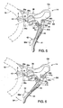
- Figure 6 is an inside elevational view, similar to Figure 5 , of the left bicycle control (brake/shift) device with the first and second shift operating levers, but with the first shift operating lever moved to a braking position such that the second shift operating lever moves with the first shift operating lever;
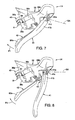
- Figure 7 is an inside perspective view of the left bicycle control (brake/shift) device with the first shift operating lever moved to a shifting position such that the second shift operating lever moves with the first shift operating lever;
- Figure 8 is an inside perspective view of the left bicycle control (brake/shift) device with the second shift operating lever moved to a shifting position with the first shift operating lever remaining stationary;
- Figure 9 is a front end view of the left bicycle control (brake/shift) device with the base member shown in phantom lines;
- Figure 10 is an enlarged partial outside perspective view of the left bicycle control (brake/shift) device with the base member removed to show the basic relationship of the first and second shift operating levers with respect to the shift control unit;
- Figure 11 is an exploded perspective view of selected parts of the shift control unit, the control member and the second shift operating lever;
- Figure 12 is an enlarged partial perspective view of selected parts of the shift control unit with the upper ends of the control member and the second shift operating lever operatively coupled to the shift control unit;
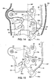
- Figure 13 is an enlarged partial elevational view of selected parts of the shift control unit and the upper ends of the control member and the second shift operating lever with the side walls of the base member being diagrammatically illustrated and the wire takeup member of the shift control unit being in a fully released position;
- Figure 14 is an enlarged partial elevational view of selected parts of the shift control unit and the upper ends of the control member and the second shift operating lever with the side walls of the base member being diagrammatically illustrated and the wire takeup member of the shift control unit being in a fully pulled position;
- Figure 15 is a simplified elevational view of selected parts of the shift control unit with the wire takeup member of the shift control unit being in the fully pulled position;
- Figure 16 is a simplified elevational view of selected parts of the shift control unit with the wire takeup member of the shift control unit being in the fully pulled position and the second shift operating lever being initially pivoted from a rest position towards the shifting position such that the release pawl engages the release plate;
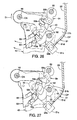
- Figure 17 is a simplified elevational view of selected parts of the shift control unit with the wire takeup member of the shift control unit being in the fully pulled position and the second shift operating lever being pivoted further from the position of Figure 16 towards the shifting position such that the release plate moves with the second shift operating lever;
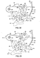
- Figure 18 is a simplified elevational view of selected parts of the shift control unit with the wire takeup member of the shift control unit being in the fully pulled position and the second shift operating lever being pivoted further from the position of Figure 17 towards the shifting position such that the positioning pawl and the winding pawl both move out of engagement from the positioning plate to allow the positioning plate and the wire takeup member rotate towards the wire released position;
- Figure 19 is a simplified elevational view of selected parts of the shift control unit with the wire takeup member of the shift control unit being released to move to the fully released position;
- Figure 20 is a simplified elevational view of selected parts of the shift control unit with the wire takeup member of the shift control unit moved to the fully released position, but with the second shift operating lever still in the shifting position;
- Figure 21 is a simplified elevational view of selected parts of the shift control unit with the wire takeup member of the shift control unit in the fully released position, and the second shift operating lever and the release plate moving back to the rest positions;
- Figure 22 is a simplified elevational view of selected parts of the shift control unit with the wire takeup member of the shift control unit in the fully released position, and the control member, the second shift operating lever and the release plate in the rest positions;
- Figure 23 is a simplified elevational view of selected parts of the shift control unit with the wire takeup member of the shift control unit in the fully released position, but with the control member being initially moved from the rest position towards the shifting position;
- Figure 24 is a simplified elevational view of selected parts of the shift control unit with the wire takeup member of the shift control unit in the fully released position, but with the control member being moved from the rest position to the low trim position;
- Figure 25 is a simplified elevational view of selected parts of the shift control unit with the wire takeup member of the shift control unit in the low trim position, but with the control member being moved from the rest position towards the shifting position such that the positioning pawl and the winding pawl both move out of engagement from the positioning plate to allow the positioning plate and the wire takeup member to be rotated towards the wire pulling position;
- Figure 26 is a simplified elevational view of selected parts of the shift control unit with the control member being moved further from the position of Figure 25 towards the shifting position such that the positioning pawl and the winding pawl both move back into engagement with the positioning plate to maintain the positioning plate and the wire takeup member in the fully pulled position; and ..
- Figure 27 is a simplified elevational view of selected parts of the shift control unit with the wire takeup member of the shift control unit in the fully pulled position, and the control member and the second shift operating lever moved back to the rest position.
- a bicycle 10 is illustrated in accordance with a pair of bicycle control devices 12 and 14 mounted on a bicycle handlebar 16 in accordance with one embodiment of the present invention.
- the bicycle control device 12 is a right hand side control device operated by the rider's right hand, while the bicycle control device 14 is a left hand side control device operated by the rider's left hand.
- the bicycle control device 12 is operatively coupled to a rear derailleur 18 via a shift control cable 20 and a rear brake device 22 via a brake control cable 24.
- the bicycle control device 14 is operatively coupled to a front derailleur 26 via a shift control cable 28 and a front brake device 30 via a brake control cable 32.
- the bicycle control devices 12 and 14 can be switched so that the rider can operate the rear derailleur 18 and the front derailleur 26 with opposite hands and/or operate the rear and front brake devices 22 and 30 with opposite hands.
- the left hand side bicycle control device 14 is substantially identical to the right hand side bicycle control device 12, except for the shifting unit (not shown) of the right hand side bicycle control device 12 has been modified to increase the number of gears that can be shifted.
- the right and left hand side bicycle control devices 12 and 14 are essentially identical in operation, except that they are mirror images of each other and the number of shift positions are different.
- the cables 20, 24, 28 and 32 are conventional bicycle control cables that have an outer casing the covers an inner wire.
- the left hand side bicycle control device 14 basically includes a base member 36, a shift control unit 38 ( Figures 9 to 11 ), a control (wire pulling) member 40, a first shift operating lever 41 and a second shift operating lever 42.
- the first shift operating lever 41 is a dual function operating lever that performs a braking operation in addition to a shifting operation.
- the bicycle control device 14 is configured and arranged to perform both a braking operation and a shifting operation as a single integrated unit that is mounted to the handlebar 16.
- the first shift operating lever 41 is configured and arranged to perform a wire pulling operation and a braking operation
- the second shift operating lever 42 is configured and arranged to perform a wire releasing operation.
- the second shift operating lever 42 is located behind the first shift operating lever 41, when the first and second shift operating levers 41 and 42 are in rest positions.
- the first and second shift operating levers 41 and 42 are aligned in a non-shift movement plane or path BP of the first shift operating lever 41, when the first and second shift operating levers 41 and 42 are in rest positions.
- the base member 36 includes a main body having a first end section 36a with a handlebar mounting structure 43 and a second end section 36b remotely disposed from the first end section 36a.
- the first and second shift operating levers 41 and 42 are located at the second end section 36b of the main body.
- the base member 36 is fixedly mounted to the handlebar 16 by the handlebar mounting structure 43, which defines a handlebar receiving area A with a central handlebar mounting axis B.
- the handlebar mounting structure 43 is preferably a conventional band clamp or similar structure.
- the main body of the base member 36 further includes an inner lateral side wall 36c and an outer lateral side wall 36d.
- the shift control unit 38 is mounted to the base member 36 generally between the lateral side walls 36c and 36d.
- the inner lateral side wall 36c has a bulging part that is shaped to accommodate a shift unit axle or main pivot shaft 44 of the shift control unit 38 as explained below.
- the inner lateral side wall 36c of the base member 36 is provided with a removable panel 36e for installing and accessing the shift control unit 38 in the base member 36. This removable panel 36e forms a portion of the bulging part of the inner lateral side wall 36c.
- the shift control unit 38 can be formed with a large lever arm LA ( Figure 13 ) for pulling and releasing the inner wire of the shift control cable 28.
- LA lever arm
- the shift control unit 38 is a cable operating device that includes a wire takeup member 51.
- the wire takeup member 51 is pivotally mounted on the shift unit axle 44, which defines a shift unit operating axis OA.
- the wire takeup member 51 is attached to the inner wire of the shift control cable 28 to pull and release the inner wire of the shift control cable 28 in response to operation of the first and second shift operating levers 41 and 42, respectively.
- the first shift operating lever 41 is operatively coupled to the shift control unit 38 via the control member 40 to operate the shift control unit 38 (mainly, the wire takeup member 51) in a first operating direction D1 or a wire pulling direction about the shift unit axle 44 of the shift control unit 38.
- the second shift operating lever 42 is operatively coupled to the shift control unit 38 to operate the shift control unit 38 (mainly, the wire takeup member 51) in a second operating direction D2 or a wire releasing direction about the shift unit axle 44 of the shift control unit 38.
- the first shift operating lever 41 preferably includes a mounting part 41a and an operating part 41b with the operating part 41b pivotally mounted to the mounting part 41a by a pivot pin 41c about a first shift operating axis SA.
- the mounting part 41a of the first shift operating lever 41 is also movably coupled relative to the base member 36 by a pivot pin 45 about a non-shift pivot axis or a brake lever pivot axis BA for performing the braking operation.
- the operating part 41b of the first shift operating lever 41 is movably coupled to mounting part 41a (i.e., relative to the base member 36) to move along a first shift operating plane or path P1 and movably coupled relative to the base member 36 to move along the non-shift (brake) movement plane or path BP that is non-coincident with the first shift operating plane or path P1.
- the operating part 41b is biased about the pivot pin 41c to a rest position with respect the first shift operating plane or path P1 by a biasing element 41d.
- a ball and recess type positioning mechanism 41e is attached to the mounting part 41a to maintain the operating part 41b of the first operating lever 41 in the rest position.
- the first shift operating lever 41 includes a cable attachment structure 41f for attaching the brake control cable 32 thereto in a conventional manner.
- the first shift operating lever 41 is operatively coupled to the shift control unit 38 via the control member 40 to operate the wire takeup member 51 of the shift control unit 38 in the first operating direction D1 as explained below.
- the first shift operating lever 41 is slidably engaged with the control member 40 such that the control member 40 is moved when the first shift operating lever 41 is moved along the non-shift (brake) movement path BP with sliding contact therebetween.
- the control member 40 moves along a plane or path Pc.
- the control member 40 moves along the non-shift (brake) movement path BP or a plane or path that is generally parallel to the non-shift (brake) movement plane or path BP.
- the first shift operating axis SA of the first shift operating lever 41 and the shift unit operating axis OA of the shift control unit 38 are offset from each other in a lateral direction of the main body of the base member 36.
- the shift unit axle 44 of the shift control unit 38 is disposed closer to the inner lateral side wall 36c than a lever pivot point PT of the first shift operating lever 41 as defined by the first shift operating axis SA.
- the lever pivot point PT of the first shift operating lever 41 is disposed closer to a midpoint or plane MP between the lateral side walls 36c and 36d than the shift unit axle 44 of the shift control unit 38.
- a head portion of the shift unit axle 44 projects out of the inner lateral side wall 36c in the illustrated embodiment.
- This arrangement allows the shift unit operating axis OA of the shift control unit 38 to be disposed very close to the inner lateral side wall 36c of the base member 36.
- the base member 36 can be easily manufactured and the shift unit axle 44 can be easily installed on the inner lateral side wall 36c of the base member 36.
- the second shift operating lever 42 is operatively coupled to the shift control unit 38 to move along a second shift operating plane or path P2 to operate the wire takeup member 51 of the shift control unit 38 in the opposite (second) operating direction D2 from the first operating direction D1 due to operation of the first shift operating lever 41.
- the second shift operating lever 42 and the control member 40 pivot about a coincident pivot axis (i.e., the shift unit operating axis OA) when performing shifting operations as explained below.
- first and second shift operating levers 41 and 42 are coupled relative to the base member 36 to move along first and second shift operating planes P1 and P2, respectively, that intersect with the non-shift (brake) movement path BP (non-shift movement plane) of the first shift operating lever 41.
- the non-shift (brake) movement path BP (non-shift movement plane) of the first shift operating lever 41 is perpendicularly oriented with respect to the first and second shift operating planes or paths P1 and P2 of the first and second shift operating levers 41 and 42
- first and second shift operating levers 41 and 42 are configured and arranged relative to each other such that they are aligned in the non-shift (brake) movement path BP to move in the non-shift (brake) movement path BP.
- the second shift operating lever 42 is located behind the first shift operating lever 41.
- the control member 40 contacts the rearward facing side of the first shift operating lever 41 and is located between the first and second shift operating levers 41 and 42.
- the first and second shift operating levers 41 and 42 are configured and arranged to pivot in a first rotational direction and a second rotational direction with respect to the base member 36 from the rest positions, respectively, with the first and second rotational directions being directions toward a central longitudinal plane of the bicycle 10.
- the first and second shift operating levers 41 and 42 are configured and arranged relative to each other such that the second shift operating lever 42 is moved by the first shift operating lever 41 when the first shift operating lever 41 is operated to move the wire takeup member 51 of shift control unit 38 in the first operating direction D1 about the shift unit axle 44 of the shift control unit 38.
- the rider pushes the first shift operating lever 41 in a direction transverse to a center plane of the base member 36 along the first shift operating plane or path P1 from the first (rest) position ( Figure 4 ) to a second (shifting) position ( Figure 7 ) to operate the shift control unit 38.
- This movement of the first shift operating lever 41 operates the wire takeup member 51 of shift control unit 38 via the control member 40 in the first operating direction D1 which is a wire pilling operation in the illustrated embodiment.
- the second shift operating lever 42 moves with the first shift operating lever 41 as the first shift operating lever 41 is moved from the first (rest) position to the second (shifting) position to operate the shift control unit 38.
- the first shift operating lever 41 pivots about the pivot pin 45 between a first (rest) position ( Figure 5 ) and a second (braking) position ( Figure 6 ) along the non-shift (brake) movement path BP.
- the movement of the first shift operating lever 41 from the rest position to the braking position results in the first and second shift operating levers 41 and 42 also being pivoted along the non-shift (brake) movement plane BP as seen in Figure 6 .
- the first and second shift operating levers 41 and 42 are configured and arranged relative to each other such that the first shift operating lever 41 remains stationary when the second shift operating lever 42 is operated to move the wire takeup member 51 of shift control unit 38 in the second operating direction D2 about the shift unit axle 44 of the shift control unit 38.
- the rider pushes the second shift operating lever 42 in a direction transverse to the center plane of the base member 36 along the second shift operating plane or path P2 from a first (rest) position to a second (shifting) position to operate the shift control unit 38.
- This movement of the second shift operating lever 42 operates the wire takeup member 51 of shift control unit 38 in the second operating direction D2 which is the wire releasing operation in the illustrated embodiment.
- the second shift operating lever 42 moves independently with respect to the first shift operating lever 41 as the second shift operating lever 42 is moved from the first (rest) position to the second (shifting) position to operate the shift control unit 38.
- the second shift operating lever 42 is a separate operating member from the first shift operating lever 41 and the second shift operating lever 42 can move independently of the first shift operating lever 41.
- the shift control unit 38 is mounted to the base member 36 by the shift unit axle 44.
- the shift control unit 38 is basically operated by the first and second shift operating levers 41 and 42 to pull or release the inner wire of the shift control cable 28 as mentioned above.
- the shift control unit 38 is also mounted to the base member 36 by the shift unit axle 44 as mentioned above.
- the shift control unit 38 further includes a wire pulling pawl 52, a positioning plate or member 53, a positioning pawl 54, a release plate or member 55 and a release pawl 56.
- the wire takeup member 51, the positioning plate 53 and the release plate 55 are all rotatably mounted on the shift unit axle 44.
- the shift unit axle 44 forms the main pivot or operating axis OA of the shift control unit 38 with the wire takeup member 51, the positioning plate 53, the release plate 55 and the second shift operating lever 42 and the control member 40 being pivotally mounted about the main pivot or operating axis OA of the shift control unit 38.
- the wire takeup member 51 and the positioning plate 53 are fixed together as an integrated unit so as to rotate together.
- the release plate 55 can rotate independently of the wire takeup member 51 and the positioning plate 53.
- the wire pulling pawl 52 is pivotally mounted on the control member 40 so as to move with the first shift operating lever 41, when the first shift operating lever 41 is moved along the first shift operating plane P1.
- the release pawl 56 is pivotally mounted on the second shift operating lever 42 so as to move with the second shift operating lever 42, when the second shift operating lever 42 is moved along the second shift operating plane P2.
- a return spring or biasing element 58 is preferably operatively coupled between the wire takeup member 51 and the base member 36 to urge the wire takeup member 51 and the positioning plate 53 in the wire releasing direction D2 about the shift unit axle 44.
- the return spring or biasing element 58 is a compression spring with one end contacting the wire takeup member 51 and the other end contacting the base member 36, as seen in Figures 10 and 11 .
- the wire takeup member 51 is also at least partially urged by a cable tension due to, for example, a pull force from the front derailleur 26.
- a return spring or biasing element 59 is preferably operatively coupled between the second shift operating lever 42 and a mounting member 60 that is attached to the base member 36.
- the return spring or biasing element 59 is a tension spring with one end fixed to the second shift operating lever 42 and the other end fixed to the mounting member 60.
- the return spring or biasing element 59 applies an urging force to the second shift operating lever 42 to bias the second shift operating lever 42 to the rest position. Since the second shift operating lever 42 abuts against the control member 40 that is held in its rest position by the positioning mechanism 41e, the second shift operating lever 42 stays in the rest position.
- the first shift operating lever 41 is configured and arranged relative to the wire takeup member 51 such that the first shift operating lever 41 performs the wire pulling operation of the wire takeup member 51 when the first shift operating lever 41 is operated.
- the second shift operating lever 42 is configured and arranged relative to the wire takeup member 51 such that the second shift operating lever 42 performs the wire releasing operation of the wire takeup member 51 when the second shift operating lever 42 is operated.
- the wire takeup member 51 is a fan shaped member that is pivotally mounted relative to the base member 36 about the pivot or operating axis OA of the shift control unit 38.
- the wire takeup member 51 is fixed to the positioning plate 53 so that the wire takeup member 51 and the positioning plate 53 move together relative to the base member 36.
- the wire takeup member 51 has a proximal end portion 51a pivotally mounted on the shift unit axle 44 and a distal end portion 51b for pulling and releasing the inner wire of the cable 28.
- the proximal end portion 51a of the wire takeup member 51 is preferably narrower than the distal end portion 51b of the wire takeup member 51.
- other shapes of the wire takeup member 51 are possible without departing from the present invention.
- the distal end portion 51b of the wire takeup member 51 has a peripheral edge with an inner wire attachment structure or point 51 c and a wire receiving groove 51d.
- the wire attachment structure or point 51c is configured to catch an enlarged head 28a of the inner wire of the control cable 28.
- the wire takeup member 51 pulls and releases the inner wire of the control cable 28 on the peripheral edge of the distal end portion 51b.
- the peripheral edge of the distal end portion 51b forms an inner wire operation point OP determining the effective lever arm LA between the pivot or operating axis OA of the shift control unit 38 and the inner wire of the control cable 28 to selectively pull and release the inner wire of the cable 28 in response to pivotal movement of the wire takeup member 51.
- the inner wire operation point OP is located radially outwardly from the wire pulling pawl 52, the positioning plate 53, the positioning pawl 54, the release plate 55 and the release pawl 56 with respect to the pivot or operating axis OA of the shift control unit 38.
- the inner wire operation point OP of the wire takeup member 51 is formed by an inner wire contact surface of the wire receiving groove 51d on the peripheral edge of the distal end portion 51b of the wire takeup member 51.
- the term "operation point” as used herein refers to a single point or an area of the inner wire takeup member 51 that determines the effective lever arm LA for controlling the effective amount of movement of the inner wire during the entire shifting operation in response to pivotally movement of the inner wire takeup member 51.
- the "operation point” can be a single attachment point, or an inner wire contact surface with an effective lever arm that either remains constant or changes during the shifting operation.
- the "operation point” can be formed by a combination of an inner wire attachment point and an inner wire contact surface with the effective lever arm either remaining constant or changing during the shifting operation.
- the wire pulling pawl 52 is pivotally mounted to the control (wire pulling) member 40, which in turn is pivotally mounted to the shift unit axle 44.
- the wire pulling pawl 52 is further pivotally arranged to engage the positioning plate 53 when the first shift operating lever 41 is moved from the rest position to the shifting position.
- the wire pulling pawl 52 is further pivotally arranged to be selectively disengaged from the positioning plate 53 in response to movement of the release plate 55 when the second shift operating lever 42 is moved from the rest position to the shifting position.
- the wire pulling pawl 52 is normally urged towards engagement with the positioning plate 53 by a biasing member 61.
- the biasing member 61 is a torsion spring that is mounted on a pivot pin 62 which in turn attaches the wire pulling pawl 52 to the control (wire pulling) member 40.
- the positioning plate 53 is fixedly coupled to the wire takeup member 51 so as to rotate together.
- the positioning plate 53 is pivotally mounted relative to the base member 36 about the main pivot or operating axis OA of the shift unit axle 44.
- the positioning plate 53 is a fan shaped member that has a narrow proximal end at the main pivot or operating axis OA of the shift unit axle 44 and a wide distal end.
- the wide distal end of the positioning plate 53 includes a plurality (three) of winding teeth or abutments 53a that are selectively engaged by the wire pulling pawl 52, and a plurality (two) of positioning teeth or abutments 53b that are selectively engaged by the positioning pawl 54.
- the wire pulling pawl 52 engages one of the winding abutments 53a of the positioning plate 53 to rotate the wire takeup member 51 in the wire pulling direction.
- the positioning pawl 54 is pivotally mounted on a pivot pin 63, which is fixedly supported by the main body of the base member 36.
- the positioning pawl 54 is normally urged towards engagement with the positioning abutments 53b of the positioning plate 53 by a biasing member 64.
- the biasing member 64 is a torsion spring that is mounted on the pivot pin 63 which in turn attach the positioning pawl 54 to the base member 36.
- positioning pawl 54 is pivotally mounted about a positioning pawl pivot axis of the pivot pin 63 to operatively engage the abutments 53b of the positioning plate 53.
- the positioning abutments 53b are selectively engaged by the positioning pawl 54 to maintain the positioning plate 53 and the wire takeup member 51 in one of a plurality of predetermined positions.
- the positioning pawl 54 moves momentarily out of holding engagement with the positioning abutments 53b of the positioning plate 53 in response to movement of the positioning plate 53.
- the inner wire operation point OP is located radially outwardly from both the positioning abutments 53b of the positioning plate 53 and a positioning pawl pivot axis of the pivot pin 63 with respect to the pivot or operating axis OA of the shift control unit 38.
- the inner wire attachment structure 51c is located radially outwardly from the positioning abutments 53b and the positioning pawl pivot axis of the pivot pin 63 with respect to the pivot or operating axis OA of the shift control unit 38.
- the release plate 55 cooperates with the positioning pawl 54 to release the wire takeup member 51 so that the wire takeup member 51 rotates in the wire releasing direction D2 due to the urging force of the return spring or biasing element 58 and a cable tension due to, for example, a pull force from the front derailleur 26.
- the release plate 55 is pivotally mounted relative to the base member 36 about the main pivot or operating axis OA of the shift unit axle 44.
- the release plate 55 and the positioning pawl 54 are configured and arranged relative to each other such that the positioning pawl 54 is moved by the release plate 55 from a retaining position that retains the positioning plate 53 in a shift position to a releasing position that releases the positioning plate 53 in response to movement of the release plate 55.
- the release plate 55 and the wire pulling pawl 52 are configured and arranged relative to each other such that the wire pulling pawl 52 is moved with respect to the positioning plate 53 in response to movement of the release plate 55 by the second shift operating lever 42.
- the release plate 55 is a fan shaped member that has a narrow proximal end at the main pivot or operating axis OA of the shift unit axle 44 and a wide distal end.
- the wide distal end of the release plate 55 includes a driving abutment 55a and a plurality (two) of release teeth or abutments 55b.
- the driving abutments 55a is selectively engaged by the release pawl 56 in response to initial movement of the second shift operating lever 42 from the rest position towards the shifting position.
- the release abutments 55b selectively engage the wire pulling pawl 52 and the positioning pawl 54 to move (pivot) them out of engagement with the winding abutments 53a and the positioning abutments 53b, respectively.
- the release plate 55 remains stationary when the first shift operating lever 41 is operated and moves when the second shift operating lever 42 is operated.
- a biasing member 65 is provided on the shift unit axle 44 to urge the release plate 55 towards the rest position in the second operating direction D2.
- the biasing member 65 is a torsion spring with the coiled portion mounted on the shift unit axle 44, a first end engaging the release plate 55 and a second end engaging a part of the base member 36.
- the release pawl 56 is movably (pivotally) mounted on the second shift operating lever 42 by a pivot pin 66, which is fixed to the second shift operating lever 42 so as to attach the release pawl 56 to the second shift operating lever 42.
- the release pawl 56 is movable from a rest position in a direction away from the main pivot or operating axis OA of the shift unit axle 44 to a release operating position.
- the release pawl 56 rest on an abutment 40a of the control (wire pulling) member 40 such that when the first shift operating lever 41 is operated, the release pawl 56 does not engage the driving abutment 55a.
- the release pawl 56 moves off of the abutment 40a of the control (wire pulling) member 40 and moves towards engagement with the driving abutment 55a of the release plate 55.
- the release pawl 56 is urged in a counterclockwise direction about the pivot pin 66 by a biasing member (not shown) in the form of a torsion spring provided with a coiled portion mounted on the pivot pin 66, a first end engaged with the release pawl 56 and a second end engaged with the second shift operating lever 42.
- the release plate 55 When the second shift operating lever 42 is moved from the first (rest) position to the second (shifting) position to operate the shift control unit 38, the release plate 55 is rotated so that the release abutments 55b selectively engage the wire pulling pawl 52 and the positioning pawl 54 to release the positioning plate 53 when the release plate 55 is rotated in the first operating direction D1.
- the release plate 55 releases the wire takeup member 51 to rotates in the wire releasing direction D2 due to the urging force of the return spring or biasing element 58 and the cable tension in response to movement of the second shift operating lever 42.
- the control (wire pulling) member 40 is pivotally mounted to the shift unit axle 44 to move along the operating plane or path Pc as mentioned above.
- the operating plane Pc intersects with the non-shift (brake) movement plane or path BP of the first shift operating lever 41 and is parallel with the second shift operating plane P2.
- the control (wire pulling) member 40 is located behind the first shift operating lever 41 and the control (wire pulling) member 40 is located in front of the second shift operating lever 42, when the first and second shift operating levers 41 and 42 are in rest positions.
- the control (wire pulling) member 40 basically includes a first lever portion 71 operatively coupled to the shift control unit 38 and a second lever portion 72 spaced from the first lever portion 71.
- the first lever portion 71 is operatively coupled to the shift control unit 38.
- the first lever portion 71 of the control member 40 is pivotally connected to the shift control unit 38 about the main pivot or operating axis OA of the shift unit axle 44 to operate the shift control unit 38 when the first shift operating lever 41 is operated along the first shift operating plane or path P1.
- the second lever portion 72 is spaced from the first lever portion 71 and contacts the rear surface of the first shift operating lever 41.
- the first shift operating lever 41 is slidably engaged with the second lever portion 72 of the control member 40 such that the second lever portion 72 of the control member 40 is moved when the first shift operating lever 41 is moved along the non-shift movement path BP with sliding contact therebetween.
- the control (wire pulling) member 40 is moved relative to the base member 36 to move the positioning plate 53 via the wire pulling pawl 52 to perform a wire pulling operation.
- a hinge pin 73 pivotally interconnects the first and second lever portions 71 and 72 together.
- a biasing element 74 is mounted on the hinge pin 73 to urge the second lever portion 72 forwardly with respect to the first lever portion 71 to a rest position.
- This intermediate hinge between the first and second lever portions 71 and 72 allows the second lever portion 72 to pivot rearwardly with respect to the first lever portion 71 such as when the first shift operating lever 41 is operated from the rest (non-braking) position to the braking position as seen in Figures 5 and 6 .
- the control member 40 includes an intermediate hinge such that the second lever portion 72 of the control member 40 is pivoted in non-operating direction when the first shift operating lever 41 is operated along the non-shift movement path BP.
- the first lever portion 71 of the control member 40 has an abutment 71a (side surface) for moving the second shift operating lever 42 when the first shift operating lever 41 is operated.
- the rider pushes the first shift operating lever 41 in a direction transverse to the non-shift (brake) movement plane or path BP of the first shift operating lever 41 along the first shift operating plane or path P1 from the first (rest) position to the second (shifting) position.
- This movement of the first shift operating lever 41 causes the control member 40 to move therewith to operate the shift control unit 38.
- the second shift operating lever 42 is pivotally mounted to the shift unit axle 44 to move along the second shift operating plane or path P2.
- the second shift operating plane P2 intersects with the non-shift (brake) movement plane or path BP of the first shift operating lever 41.
- the second shift operating lever 2 and the control member 40 pivot about a coincident pivot axis of the shift unit axle 44 when performing shifting operations.
- the second shift operating lever 42 is located behind the first shift operating lever 41, when the first and second shift operating levers 41 and 42 are in rest positions.
- the second shift operating lever 42 is operatively arranged to rotate the positioning plate 53 about the main pivot or operating axis OA of the shift unit axle 44 in the second operating direction D2 via movement of the release plate 55 by the operation of the second shift operating lever 42.
- the second shift operating lever 42 basically includes a first lever portion 81 operatively coupled to the shift control unit 38 and a second lever portion 82 spaced from the first lever portion 81.
- a hinge pin 83 pivotally interconnects the first and second lever portions 81 and 82 together.
- a biasing element 84 is mounted on the hinge pin 83 to urge the second lever portion 82 forwardly with respect to the first lever portion 81 to a rest position.
- This hinge between the first and second lever portions 81 and 82 allows the second lever portion 82 to pivot rearwardly with respect to the first lever portion 81 such as when the first shift operating lever 41 is operated from the rest (non-braking) position to the braking position as seen in Figures 5 and 6 .
- the second shift operating lever 42 includes a hinge such that the second lever portion 82 of the second shift operating lever 42 is pivoted in a non-operating direction when the first shift operating lever 41 is operated along the non-shift movement path BP.
- the first lever portion 81 of the second shift operating lever 42 has an abutment 81a (flange) contacts the abutment 71a of the control member 40 such that the second shift operating lever 42 moves with the first shift operating lever 41 when the first shift operating lever 41 is operated.
- the abutments 71a and 81a are configured and arranged relative to each other such that the second shift operating lever 42 is moved by the first shift operating lever 41.
- the second lever portion 82 of the second shift operating lever 42 has a finger contact portion 82a located at the end opposite the hinge for moving the second shift operating lever 42 about the shift unit axle 44 of the shift control unit 38.
- the rider pushes the finger contact portion 82a of the second shift operating lever 42 in a direction transverse to the non-shift (brake) movement plane or path BP of the first shift operating lever 41 along the second shift operating plane or path P2 from the first (rest) position to the second (shifting) position to operate the shift control unit 38.
- Figures 16 to 21 illustrate an inner wire releasing operation
- Figures 22 to 27 illustrate an inner wire pulling operation
- the fully wire pulled position of Figure 16 is a low gear position of the shift control unit 38 for holding the front derailleur 26 in a low gear position
- the fully wire released position of Figure 22 is a top gear position of the shift control unit 38 for holding the front derailleur 26 in a top gear position
- Figure 24 illustrates a low gear trim position of the shift control unit 38 for holding the front derailleur 26 in a low gear trim position.
- the first shift operating lever 41 In the case of a wire pulling operation, the first shift operating lever 41 is moved from the rest position to the shifting position which in turn moves the control (wire pulling) member 40, which is pivotally mounted to the shift unit axle 44. This pivotally movement of the control (wire pulling) member 40 to the shifting position causes the second shift operating lever 42 to pivot with the first shift operating lever 41 as shown in Figure 7 .
- the first shift operating lever 41 will not be shown in Figures 22 to 27 . Rather, only the movement of the control (wire pulling) member 40 and the second shift operating lever 42 will be illustrated in phantom lines in Figures 22 to 27 .
- the control (wire pulling) member 40 is moved by the first shift operating lever 41 such that either a low gear trim position is attained by partial movement of the first shift operating lever 41 as seen in Figure 23 or a top gear position is attained by complete or subsequent movement of the first shift operating lever 41 past the low gear trim position to the top gear position as seen in Figure 27 .
- the winding pawl 52 engages one of the winding abutments 53a of the positioning plate 53 to rotate the positioning plate 53 and the wire takeup member 51 in the wire pulling direction.
- the positioning pawl 54 is pivoted to engage the low gear trim abutment of the positioning abutments 53b.
- the first shift operating lever 41 can now be release to attain the position in Figure 24 , if a low gear trim position is desired or moved further to attain the position in Figure 27 , if a top gear position is desired.
- the top gear position can also be attained from the low gear trim position as seen in Figures 24 to 27 .
- the shift control unit 38 is illustrated as a cable operating shift control unit, which is merely one example of a shift control unit that can be used with the bicycle control device 14.
- the shift control unit for the bicycle control device 14 is not limited to a cable operating system, but rather other types of shift control units can be used with the bicycle control device 14 described and illustrated herein.
- the shift control unit 38 can be replaced an electrical shift control unit, or a pneumatic shift control unit, or hydraulic shift control unit.
- an electrical shift control unit at least a pair of electrical switches would be provided for performing upshift and downshift operations in response to selective movements of the first and second shift operating levers 41 and 42.
- a valve system would be provided for performing upshift and downshift operations in response to selective movements of the first and second shift operating levers 41 and 42.
- the term “configured” as used herein to describe a component, section or part of a device includes hardware and/or software that is constructed and/or programmed to carry out the desired function.
- the term “comprising” and its derivatives, as used herein are intended to be open ended terms that specify the presence of the stated features, elements, components, groups, integers, and/or steps, but do not exclude the presence of other unstated features, elements, components, groups, integers and/or steps.
- the foregoing also applies to words having similar meanings such as the terms, “including”, “having” and their derivatives.
- the terms "part,” “section,” “portion,” “member” or “element” when used in the singular can have the dual meaning of a single part or a plurality of parts.
- the following directional terms “forward, rearward, above, downward, vertical, horizontal, below and transverse” as well as any other similar directional terms refer to those directions of a bicycle equipped with the present invention. Accordingly, these terms, as utilized to describe the present invention should be interpreted relative to a bicycle equipped with the present invention as used in the normal riding position.
- terms of degree such as “substantially”, “about” and “approximately” as used herein mean a reasonable amount of deviation of the modified term such that the end result is not significantly changed.
Abstract
Description
- This invention generally relates to a bicycle control device for operating a bicycle component. More specifically, the present invention relates to a bicycle control (component actuating) device that has a shift operating member with a pivot axis that is offset from a shift unit operating axis of a shift control unit.
- Bicycling is becoming an increasingly more popular form of recreation as well as a means of transportation. Moreover, bicycling has become a very popular competitive sport for both amateurs and professionals. Whether the bicycle is used for recreation, transportation or competition, the bicycle industry is constantly improving the various components of the bicycle, especially the bicycle control devices for performing shifting and braking operations.
- Typically, bicycle shifters mechanically operate derailleurs via cables, while bicycle brake levers mechanically operate brake devices via cables. In either case, an operating force is typically applied by one of the rider's fingers to operate a control lever, which in turn transmitted the operating force to the drive component of a bicycle shifting mechanism by a cable that was fixed at one end to the control lever. Currently, many different types of control devices exist for performing shifting and braking operations.
- Sometimes the bicycle shifter and the bicycle brake lever are combined as a single integrated unit, while other times they are separate individual units. In the case of road bikes with drop type handlebars, the bicycle shifter and the bicycle brake lever are often combined as a single integrated control device. In some cases, a braking function and a shifting function is performed by a single dual function lever, One example of this type of control device is disclosed in
U.S. Patent No. 5,400,675 to Nagano (assigned to Shimano, Inc). More typically, one or two shift levers are provided in addition to the brake lever. One example of this type of control device is disclosed inU.S. Patent No. 5,257,683 to Romano (assigned to Campagnolo). While these types of control devices work well, it is desirable to provide a bicycle control (component actuating) device that is relatively easily to manufacture and that is relatively easily for a rider to operate. - In view of the above, it will be apparent to those skilled in the art from this disclosure that there exists a need for an improved bicycle component actuating device. This invention addresses this need in the art as well as other needs, which will become apparent to those skilled in the art from this disclosure.
- One object of the present invention is to provide a control (component actuating) device that has a shift operating member with a pivot axis that is offset from a shift unit operating axis of a shift control unit.
- The foregoing objects can basically be attained by providing a bicycle control device that basically comprises a base member, a shift control unit and a first shift operating lever. The base member includes a pair of lateral side walls. The shift control unit is mounted to the base member. The shift control unit has a main pivot shaft defining a shift unit operating axis. The first shift operating lever is operatively coupled to the shift control unit to operate the shift control unit when the first shift operating lever is pivoted about a first shift operating axis at a lever pivot point. The main pivot shaft of the shift control unit is disposed closer to one of the lateral side walls than the lever pivot point of the first shift operating lever.
- These and other objects, features, aspects and advantages of the present invention will become apparent to those skilled in the art from the following detailed description, which, taken in conjunction with the annexed drawings, discloses a preferred embodiment of the present invention.
- Referring now to the attached drawings which form a part of this original disclosure:
-
Figure 1 is a side elevational view of bicycle equipped with a bicycle control (brake/shift) device coupled to a drop type handlebar in accordance with a preferred embodiment of the present invention; -
Figure 2 is an enlarged partial perspective view of the drop type handlebar with the bicycle control (brake/shift) device in accordance with the illustrated embodiment of the present invention; -
Figure 3 is an inside elevational view of the left bicycle control (brake/shift) device with the first and second shift operating levers in the rest positions; -
Figure 4 is an outside perspective view of the left bicycle control (brake/shift) device with the first and second shift operating levers in the rest positions; -
Figure 5 is an inside elevational view of the left bicycle control (brake/shift) device with the first and second shift operating levers in the rest positions and a portion of the first shift operating lever broken away to illustrate the sliding connection between the first shift operating lever and the control lever; -
Figure 6 is an inside elevational view, similar toFigure 5 , of the left bicycle control (brake/shift) device with the first and second shift operating levers, but with the first shift operating lever moved to a braking position such that the second shift operating lever moves with the first shift operating lever; -
Figure 7 is an inside perspective view of the left bicycle control (brake/shift) device with the first shift operating lever moved to a shifting position such that the second shift operating lever moves with the first shift operating lever; -
Figure 8 is an inside perspective view of the left bicycle control (brake/shift) device with the second shift operating lever moved to a shifting position with the first shift operating lever remaining stationary; -
Figure 9 is a front end view of the left bicycle control (brake/shift) device with the base member shown in phantom lines; -
Figure 10 is an enlarged partial outside perspective view of the left bicycle control (brake/shift) device with the base member removed to show the basic relationship of the first and second shift operating levers with respect to the shift control unit; -
Figure 11 is an exploded perspective view of selected parts of the shift control unit, the control member and the second shift operating lever; -
Figure 12 is an enlarged partial perspective view of selected parts of the shift control unit with the upper ends of the control member and the second shift operating lever operatively coupled to the shift control unit; -
Figure 13 is an enlarged partial elevational view of selected parts of the shift control unit and the upper ends of the control member and the second shift operating lever with the side walls of the base member being diagrammatically illustrated and the wire takeup member of the shift control unit being in a fully released position; -
Figure 14 is an enlarged partial elevational view of selected parts of the shift control unit and the upper ends of the control member and the second shift operating lever with the side walls of the base member being diagrammatically illustrated and the wire takeup member of the shift control unit being in a fully pulled position; -
Figure 15 is a simplified elevational view of selected parts of the shift control unit with the wire takeup member of the shift control unit being in the fully pulled position; -
Figure 16 is a simplified elevational view of selected parts of the shift control unit with the wire takeup member of the shift control unit being in the fully pulled position and the second shift operating lever being initially pivoted from a rest position towards the shifting position such that the release pawl engages the release plate; -
Figure 17 is a simplified elevational view of selected parts of the shift control unit with the wire takeup member of the shift control unit being in the fully pulled position and the second shift operating lever being pivoted further from the position ofFigure 16 towards the shifting position such that the release plate moves with the second shift operating lever; -
Figure 18 is a simplified elevational view of selected parts of the shift control unit with the wire takeup member of the shift control unit being in the fully pulled position and the second shift operating lever being pivoted further from the position ofFigure 17 towards the shifting position such that the positioning pawl and the winding pawl both move out of engagement from the positioning plate to allow the positioning plate and the wire takeup member rotate towards the wire released position; -
Figure 19 is a simplified elevational view of selected parts of the shift control unit with the wire takeup member of the shift control unit being released to move to the fully released position; -
Figure 20 is a simplified elevational view of selected parts of the shift control unit with the wire takeup member of the shift control unit moved to the fully released position, but with the second shift operating lever still in the shifting position; -
Figure 21 is a simplified elevational view of selected parts of the shift control unit with the wire takeup member of the shift control unit in the fully released position, and the second shift operating lever and the release plate moving back to the rest positions; -
Figure 22 is a simplified elevational view of selected parts of the shift control unit with the wire takeup member of the shift control unit in the fully released position, and the control member, the second shift operating lever and the release plate in the rest positions; -
Figure 23 is a simplified elevational view of selected parts of the shift control unit with the wire takeup member of the shift control unit in the fully released position, but with the control member being initially moved from the rest position towards the shifting position; -
Figure 24 is a simplified elevational view of selected parts of the shift control unit with the wire takeup member of the shift control unit in the fully released position, but with the control member being moved from the rest position to the low trim position; -
Figure 25 is a simplified elevational view of selected parts of the shift control unit with the wire takeup member of the shift control unit in the low trim position, but with the control member being moved from the rest position towards the shifting position such that the positioning pawl and the winding pawl both move out of engagement from the positioning plate to allow the positioning plate and the wire takeup member to be rotated towards the wire pulling position; -
Figure 26 is a simplified elevational view of selected parts of the shift control unit with the control member being moved further from the position ofFigure 25 towards the shifting position such that the positioning pawl and the winding pawl both move back into engagement with the positioning plate to maintain the positioning plate and the wire takeup member in the fully pulled position; and .. -
Figure 27 is a simplified elevational view of selected parts of the shift control unit with the wire takeup member of the shift control unit in the fully pulled position, and the control member and the second shift operating lever moved back to the rest position. - Selected embodiments of the present invention will now be explained with reference to the drawings. It will be apparent to those skilled in the art from this disclosure that the following descriptions of the embodiments of the present invention are provided for illustration only and not for the purpose of limiting the invention as defined by the appended claims and their equivalents.
- Referring initially to
Figures 1 and 2 , abicycle 10 is illustrated in accordance with a pair ofbicycle control devices bicycle handlebar 16 in accordance with one embodiment of the present invention. Thebicycle control device 12 is a right hand side control device operated by the rider's right hand, while thebicycle control device 14 is a left hand side control device operated by the rider's left hand. In the illustrated embodiment, thebicycle control device 12 is operatively coupled to arear derailleur 18 via ashift control cable 20 and arear brake device 22 via abrake control cable 24. Thebicycle control device 14 is operatively coupled to afront derailleur 26 via ashift control cable 28 and afront brake device 30 via abrake control cable 32. Alternatively, thebicycle control devices rear derailleur 18 and thefront derailleur 26 with opposite hands and/or operate the rear andfront brake devices bicycle control device 14 is substantially identical to the right hand sidebicycle control device 12, except for the shifting unit (not shown) of the right hand sidebicycle control device 12 has been modified to increase the number of gears that can be shifted. In any event, the right and left hand sidebicycle control devices bicycle control device 14 will be discussed and illustrated herein. Preferably, thecables - Referring now to
Figures 3 to 11 , the left hand sidebicycle control device 14 basically includes abase member 36, a shift control unit 38 (Figures 9 to 11 ), a control (wire pulling)member 40, a firstshift operating lever 41 and a secondshift operating lever 42. The firstshift operating lever 41 is a dual function operating lever that performs a braking operation in addition to a shifting operation. Thus, thebicycle control device 14 is configured and arranged to perform both a braking operation and a shifting operation as a single integrated unit that is mounted to thehandlebar 16. In the illustrated embodiment, the firstshift operating lever 41 is configured and arranged to perform a wire pulling operation and a braking operation, while the secondshift operating lever 42 is configured and arranged to perform a wire releasing operation. The secondshift operating lever 42 is located behind the firstshift operating lever 41, when the first and second shift operating levers 41 and 42 are in rest positions. The first and second shift operating levers 41 and 42 are aligned in a non-shift movement plane or path BP of the firstshift operating lever 41, when the first and second shift operating levers 41 and 42 are in rest positions. - As best seen in
Figures 3 and4 , thebase member 36 includes a main body having afirst end section 36a with ahandlebar mounting structure 43 and asecond end section 36b remotely disposed from thefirst end section 36a. The first and second shift operating levers 41 and 42 are located at thesecond end section 36b of the main body. Thebase member 36 is fixedly mounted to thehandlebar 16 by thehandlebar mounting structure 43, which defines a handlebar receiving area A with a central handlebar mounting axis B. Thehandlebar mounting structure 43 is preferably a conventional band clamp or similar structure. - As seen in
Figures 3 to 8 and12 , the main body of thebase member 36 further includes an innerlateral side wall 36c and an outerlateral side wall 36d. Theshift control unit 38 is mounted to thebase member 36 generally between thelateral side walls lateral side wall 36c has a bulging part that is shaped to accommodate a shift unit axle ormain pivot shaft 44 of theshift control unit 38 as explained below. As seen inFigures 5 and 6 , the innerlateral side wall 36c of thebase member 36 is provided with aremovable panel 36e for installing and accessing theshift control unit 38 in thebase member 36. Thisremovable panel 36e forms a portion of the bulging part of the innerlateral side wall 36c. By having theshift unit axle 44 of theshift control unit 38 disposed closely adjacent the innerlateral side wall 36c, theshift control unit 38 can be formed with a large lever arm LA (Figure 13 ) for pulling and releasing the inner wire of theshift control cable 28. In this way, the firstshift operating lever 41 can be moved a short distance (stroke) while still pulling the inner wire of theshift control cable 28 by the necessary amount for causing a shift to occur. - In the illustrated embodiment, as seen in
Figures 9 to 11 , theshift control unit 38 is a cable operating device that includes awire takeup member 51. Thewire takeup member 51 is pivotally mounted on theshift unit axle 44, which defines a shift unit operating axis OA. Thewire takeup member 51 is attached to the inner wire of theshift control cable 28 to pull and release the inner wire of theshift control cable 28 in response to operation of the first and second shift operating levers 41 and 42, respectively. - The first
shift operating lever 41 is operatively coupled to theshift control unit 38 via thecontrol member 40 to operate the shift control unit 38 (mainly, the wire takeup member 51) in a first operating direction D1 or a wire pulling direction about theshift unit axle 44 of theshift control unit 38. The secondshift operating lever 42 is operatively coupled to theshift control unit 38 to operate the shift control unit 38 (mainly, the wire takeup member 51) in a second operating direction D2 or a wire releasing direction about theshift unit axle 44 of theshift control unit 38. - The first
shift operating lever 41 preferably includes a mountingpart 41a and anoperating part 41b with the operatingpart 41b pivotally mounted to the mountingpart 41a by apivot pin 41c about a first shift operating axis SA. The mountingpart 41a of the firstshift operating lever 41 is also movably coupled relative to thebase member 36 by apivot pin 45 about a non-shift pivot axis or a brake lever pivot axis BA for performing the braking operation. Thus, the operatingpart 41b of the firstshift operating lever 41 is movably coupled to mountingpart 41a (i.e., relative to the base member 36) to move along a first shift operating plane or path P1 and movably coupled relative to thebase member 36 to move along the non-shift (brake) movement plane or path BP that is non-coincident with the first shift operating plane or path P1. The operatingpart 41b is biased about thepivot pin 41c to a rest position with respect the first shift operating plane or path P1 by a biasingelement 41d. As seen inFigure 9 , a ball and recesstype positioning mechanism 41e is attached to the mountingpart 41a to maintain theoperating part 41b of thefirst operating lever 41 in the rest position. Also, as seen inFigure 9 , the firstshift operating lever 41 includes acable attachment structure 41f for attaching thebrake control cable 32 thereto in a conventional manner. - The first
shift operating lever 41 is operatively coupled to theshift control unit 38 via thecontrol member 40 to operate thewire takeup member 51 of theshift control unit 38 in the first operating direction D1 as explained below. The firstshift operating lever 41 is slidably engaged with thecontrol member 40 such that thecontrol member 40 is moved when the firstshift operating lever 41 is moved along the non-shift (brake) movement path BP with sliding contact therebetween. Thus, when the firstshift operating lever 41 is operated along the first shift operating plane or path P1, thecontrol member 40 moves along a plane or path Pc. When the firstshift operating lever 41 is operated along the non-shift (brake) movement path BP, thecontrol member 40 moves along the non-shift (brake) movement path BP or a plane or path that is generally parallel to the non-shift (brake) movement plane or path BP. - In the illustrated embodiment, the first shift operating axis SA of the first
shift operating lever 41 and the shift unit operating axis OA of theshift control unit 38 are offset from each other in a lateral direction of the main body of thebase member 36. Preferably, theshift unit axle 44 of theshift control unit 38 is disposed closer to the innerlateral side wall 36c than a lever pivot point PT of the firstshift operating lever 41 as defined by the first shift operating axis SA. In particular, the lever pivot point PT of the firstshift operating lever 41 is disposed closer to a midpoint or plane MP between thelateral side walls shift unit axle 44 of theshift control unit 38. In fact, as seen inFigures 5 to 8 , a head portion of theshift unit axle 44 projects out of the innerlateral side wall 36c in the illustrated embodiment. This arrangement allows the shift unit operating axis OA of theshift control unit 38 to be disposed very close to the innerlateral side wall 36c of thebase member 36. Moreover, since the head portion of theshift unit axle 44 projects out of the innerlateral side wall 36c, thebase member 36 can be easily manufactured and theshift unit axle 44 can be easily installed on the innerlateral side wall 36c of thebase member 36. - The second
shift operating lever 42 is operatively coupled to theshift control unit 38 to move along a second shift operating plane or path P2 to operate thewire takeup member 51 of theshift control unit 38 in the opposite (second) operating direction D2 from the first operating direction D1 due to operation of the firstshift operating lever 41. The secondshift operating lever 42 and thecontrol member 40 pivot about a coincident pivot axis (i.e., the shift unit operating axis OA) when performing shifting operations as explained below. - Thus, the first and second shift operating levers 41 and 42 are coupled relative to the
base member 36 to move along first and second shift operating planes P1 and P2, respectively, that intersect with the non-shift (brake) movement path BP (non-shift movement plane) of the firstshift operating lever 41. The non-shift (brake) movement path BP (non-shift movement plane) of the firstshift operating lever 41 is perpendicularly oriented with respect to the first and second shift operating planes or paths P1 and P2 of the first and second shift operating levers 41 and 42 - Now referring to
Figures 4 to 8 , the movements of the first and second shift operating levers 41 and 42 will now be generally discussed with respect to thebase member 36 that is configured to be fixedly mounted to thehandlebar 16 by thehandlebar mounting structure 43. In this illustrated embodiment, the first and second shift operating levers 41 and 42 are configured and arranged relative to each other such that they are aligned in the non-shift (brake) movement path BP to move in the non-shift (brake) movement path BP. In particular, the secondshift operating lever 42 is located behind the firstshift operating lever 41. Thecontrol member 40 contacts the rearward facing side of the firstshift operating lever 41 and is located between the first and second shift operating levers 41 and 42. The first and second shift operating levers 41 and 42 are configured and arranged to pivot in a first rotational direction and a second rotational direction with respect to thebase member 36 from the rest positions, respectively, with the first and second rotational directions being directions toward a central longitudinal plane of thebicycle 10. - As seen in
Figures 4 and7 , in this illustrated embodiment, the first and second shift operating levers 41 and 42 are configured and arranged relative to each other such that the secondshift operating lever 42 is moved by the firstshift operating lever 41 when the firstshift operating lever 41 is operated to move thewire takeup member 51 ofshift control unit 38 in the first operating direction D1 about theshift unit axle 44 of theshift control unit 38. In other words, when a wire pulling operation is desired, the rider pushes the firstshift operating lever 41 in a direction transverse to a center plane of thebase member 36 along the first shift operating plane or path P1 from the first (rest) position (Figure 4 ) to a second (shifting) position (Figure 7 ) to operate theshift control unit 38. This movement of the firstshift operating lever 41 operates thewire takeup member 51 ofshift control unit 38 via thecontrol member 40 in the first operating direction D1 which is a wire pilling operation in the illustrated embodiment. As mentioned above, the secondshift operating lever 42 moves with the firstshift operating lever 41 as the firstshift operating lever 41 is moved from the first (rest) position to the second (shifting) position to operate theshift control unit 38. - As seen in
Figures 5 and 6 , in the illustrated embodiment, the firstshift operating lever 41 pivots about thepivot pin 45 between a first (rest) position (Figure 5 ) and a second (braking) position (Figure 6 ) along the non-shift (brake) movement path BP. The movement of the firstshift operating lever 41 from the rest position to the braking position results in the first and second shift operating levers 41 and 42 also being pivoted along the non-shift (brake) movement plane BP as seen inFigure 6 . - As seen in
Figures 4 and8 , in this illustrated embodiment, the first and second shift operating levers 41 and 42 are configured and arranged relative to each other such that the firstshift operating lever 41 remains stationary when the secondshift operating lever 42 is operated to move thewire takeup member 51 ofshift control unit 38 in the second operating direction D2 about theshift unit axle 44 of theshift control unit 38. In other words, when a wire releasing operation is desired, the rider pushes the secondshift operating lever 42 in a direction transverse to the center plane of thebase member 36 along the second shift operating plane or path P2 from a first (rest) position to a second (shifting) position to operate theshift control unit 38. This movement of the secondshift operating lever 42 operates thewire takeup member 51 ofshift control unit 38 in the second operating direction D2 which is the wire releasing operation in the illustrated embodiment. As mentioned above, the secondshift operating lever 42 moves independently with respect to the firstshift operating lever 41 as the secondshift operating lever 42 is moved from the first (rest) position to the second (shifting) position to operate theshift control unit 38. - Thus, the second
shift operating lever 42 is a separate operating member from the firstshift operating lever 41 and the secondshift operating lever 42 can move independently of the firstshift operating lever 41. - Referring now to
Figures 9 to 11 , theshift control unit 38 will now be discussed in more detail. Theshift control unit 38 is mounted to thebase member 36 by theshift unit axle 44. Theshift control unit 38 is basically operated by the first and second shift operating levers 41 and 42 to pull or release the inner wire of theshift control cable 28 as mentioned above. Theshift control unit 38 is also mounted to thebase member 36 by theshift unit axle 44 as mentioned above. - In addition to the
wire takeup member 51, mentioned above, theshift control unit 38 further includes awire pulling pawl 52, a positioning plate ormember 53, apositioning pawl 54, a release plate ormember 55 and arelease pawl 56. Thewire takeup member 51, thepositioning plate 53 and therelease plate 55 are all rotatably mounted on theshift unit axle 44. In other words, theshift unit axle 44 forms the main pivot or operating axis OA of theshift control unit 38 with thewire takeup member 51, thepositioning plate 53, therelease plate 55 and the secondshift operating lever 42 and thecontrol member 40 being pivotally mounted about the main pivot or operating axis OA of theshift control unit 38. Thewire takeup member 51 and thepositioning plate 53 are fixed together as an integrated unit so as to rotate together. Therelease plate 55 can rotate independently of thewire takeup member 51 and thepositioning plate 53. Thewire pulling pawl 52 is pivotally mounted on thecontrol member 40 so as to move with the firstshift operating lever 41, when the firstshift operating lever 41 is moved along the first shift operating plane P1. Therelease pawl 56 is pivotally mounted on the secondshift operating lever 42 so as to move with the secondshift operating lever 42, when the secondshift operating lever 42 is moved along the second shift operating plane P2. - A return spring or biasing
element 58 is preferably operatively coupled between thewire takeup member 51 and thebase member 36 to urge thewire takeup member 51 and thepositioning plate 53 in the wire releasing direction D2 about theshift unit axle 44. In the illustrated embodiment, the return spring or biasingelement 58 is a compression spring with one end contacting thewire takeup member 51 and the other end contacting thebase member 36, as seen inFigures 10 and11 . Thewire takeup member 51 is also at least partially urged by a cable tension due to, for example, a pull force from thefront derailleur 26. - A return spring or biasing
element 59 is preferably operatively coupled between the secondshift operating lever 42 and a mountingmember 60 that is attached to thebase member 36. In the illustrated embodiment, the return spring or biasingelement 59 is a tension spring with one end fixed to the secondshift operating lever 42 and the other end fixed to the mountingmember 60. The return spring or biasingelement 59 applies an urging force to the secondshift operating lever 42 to bias the secondshift operating lever 42 to the rest position. Since the secondshift operating lever 42 abuts against thecontrol member 40 that is held in its rest position by thepositioning mechanism 41e, the secondshift operating lever 42 stays in the rest position. - As mentioned above, the first
shift operating lever 41 is configured and arranged relative to thewire takeup member 51 such that the firstshift operating lever 41 performs the wire pulling operation of thewire takeup member 51 when the firstshift operating lever 41 is operated. The secondshift operating lever 42 is configured and arranged relative to thewire takeup member 51 such that the secondshift operating lever 42 performs the wire releasing operation of thewire takeup member 51 when the secondshift operating lever 42 is operated. - The
wire takeup member 51 is a fan shaped member that is pivotally mounted relative to thebase member 36 about the pivot or operating axis OA of theshift control unit 38. Thewire takeup member 51 is fixed to thepositioning plate 53 so that thewire takeup member 51 and thepositioning plate 53 move together relative to thebase member 36. Thewire takeup member 51 has aproximal end portion 51a pivotally mounted on theshift unit axle 44 and adistal end portion 51b for pulling and releasing the inner wire of thecable 28. Theproximal end portion 51a of thewire takeup member 51 is preferably narrower than thedistal end portion 51b of thewire takeup member 51. However, other shapes of thewire takeup member 51 are possible without departing from the present invention. - The
distal end portion 51b of thewire takeup member 51 has a peripheral edge with an inner wire attachment structure orpoint 51 c and awire receiving groove 51d. The wire attachment structure orpoint 51c is configured to catch anenlarged head 28a of the inner wire of thecontrol cable 28. Thus, thewire takeup member 51 pulls and releases the inner wire of thecontrol cable 28 on the peripheral edge of thedistal end portion 51b. The peripheral edge of thedistal end portion 51b forms an inner wire operation point OP determining the effective lever arm LA between the pivot or operating axis OA of theshift control unit 38 and the inner wire of thecontrol cable 28 to selectively pull and release the inner wire of thecable 28 in response to pivotal movement of thewire takeup member 51. The inner wire operation point OP is located radially outwardly from thewire pulling pawl 52, thepositioning plate 53, thepositioning pawl 54, therelease plate 55 and therelease pawl 56 with respect to the pivot or operating axis OA of theshift control unit 38. In this embodiment, the inner wire operation point OP of thewire takeup member 51 is formed by an inner wire contact surface of thewire receiving groove 51d on the peripheral edge of thedistal end portion 51b of thewire takeup member 51. - Referring to
Figure 13 , the term "operation point" as used herein refers to a single point or an area of the innerwire takeup member 51 that determines the effective lever arm LA for controlling the effective amount of movement of the inner wire during the entire shifting operation in response to pivotally movement of the innerwire takeup member 51. In other words, for example, the "operation point" can be a single attachment point, or an inner wire contact surface with an effective lever arm that either remains constant or changes during the shifting operation. Of course, it will also be apparent from this disclosure that the "operation point" can be formed by a combination of an inner wire attachment point and an inner wire contact surface with the effective lever arm either remaining constant or changing during the shifting operation. - The
wire pulling pawl 52 is pivotally mounted to the control (wire pulling)member 40, which in turn is pivotally mounted to theshift unit axle 44. Thewire pulling pawl 52 is further pivotally arranged to engage thepositioning plate 53 when the firstshift operating lever 41 is moved from the rest position to the shifting position. Thewire pulling pawl 52 is further pivotally arranged to be selectively disengaged from thepositioning plate 53 in response to movement of therelease plate 55 when the secondshift operating lever 42 is moved from the rest position to the shifting position. Thewire pulling pawl 52 is normally urged towards engagement with thepositioning plate 53 by a biasingmember 61. In this illustrated embodiment, the biasingmember 61 is a torsion spring that is mounted on apivot pin 62 which in turn attaches thewire pulling pawl 52 to the control (wire pulling)member 40. - The
positioning plate 53 is fixedly coupled to thewire takeup member 51 so as to rotate together. Thepositioning plate 53 is pivotally mounted relative to thebase member 36 about the main pivot or operating axis OA of theshift unit axle 44. In particular, thepositioning plate 53 is a fan shaped member that has a narrow proximal end at the main pivot or operating axis OA of theshift unit axle 44 and a wide distal end. The wide distal end of thepositioning plate 53 includes a plurality (three) of winding teeth orabutments 53a that are selectively engaged by thewire pulling pawl 52, and a plurality (two) of positioning teeth orabutments 53b that are selectively engaged by thepositioning pawl 54. When the firstshift operating lever 41 is moved from the first (rest) position to the second (shifting) position to operate theshift control unit 38, thewire pulling pawl 52 engages one of the windingabutments 53a of thepositioning plate 53 to rotate thewire takeup member 51 in the wire pulling direction. - The
positioning pawl 54 is pivotally mounted on apivot pin 63, which is fixedly supported by the main body of thebase member 36. Thepositioning pawl 54 is normally urged towards engagement with thepositioning abutments 53b of thepositioning plate 53 by a biasingmember 64. In this illustrated embodiment, the biasingmember 64 is a torsion spring that is mounted on thepivot pin 63 which in turn attach thepositioning pawl 54 to thebase member 36. Thus, positioningpawl 54 is pivotally mounted about a positioning pawl pivot axis of thepivot pin 63 to operatively engage theabutments 53b of thepositioning plate 53. In other words, thepositioning abutments 53b are selectively engaged by thepositioning pawl 54 to maintain thepositioning plate 53 and thewire takeup member 51 in one of a plurality of predetermined positions. When the firstshift operating lever 41 is moved from the first (rest) position to the second (shifting) position to operate theshift control unit 38, thepositioning pawl 54 moves momentarily out of holding engagement with thepositioning abutments 53b of thepositioning plate 53 in response to movement of thepositioning plate 53. - In this illustrated embodiment, the inner wire operation point OP is located radially outwardly from both the
positioning abutments 53b of thepositioning plate 53 and a positioning pawl pivot axis of thepivot pin 63 with respect to the pivot or operating axis OA of theshift control unit 38. Likewise, the innerwire attachment structure 51c is located radially outwardly from thepositioning abutments 53b and the positioning pawl pivot axis of thepivot pin 63 with respect to the pivot or operating axis OA of theshift control unit 38. - The
release plate 55 cooperates with thepositioning pawl 54 to release thewire takeup member 51 so that thewire takeup member 51 rotates in the wire releasing direction D2 due to the urging force of the return spring or biasingelement 58 and a cable tension due to, for example, a pull force from thefront derailleur 26. Therelease plate 55 is pivotally mounted relative to thebase member 36 about the main pivot or operating axis OA of theshift unit axle 44. Therelease plate 55 and thepositioning pawl 54 are configured and arranged relative to each other such that thepositioning pawl 54 is moved by therelease plate 55 from a retaining position that retains thepositioning plate 53 in a shift position to a releasing position that releases thepositioning plate 53 in response to movement of therelease plate 55. Also therelease plate 55 and thewire pulling pawl 52 are configured and arranged relative to each other such that thewire pulling pawl 52 is moved with respect to thepositioning plate 53 in response to movement of therelease plate 55 by the secondshift operating lever 42. - The
release plate 55 is a fan shaped member that has a narrow proximal end at the main pivot or operating axis OA of theshift unit axle 44 and a wide distal end. In particular, the wide distal end of therelease plate 55 includes a drivingabutment 55a and a plurality (two) of release teeth orabutments 55b. The drivingabutments 55a is selectively engaged by therelease pawl 56 in response to initial movement of the secondshift operating lever 42 from the rest position towards the shifting position. Upon rotation of therelease plate 55, therelease abutments 55b selectively engage thewire pulling pawl 52 and thepositioning pawl 54 to move (pivot) them out of engagement with the windingabutments 53a and thepositioning abutments 53b, respectively. Basically, therelease plate 55 remains stationary when the firstshift operating lever 41 is operated and moves when the secondshift operating lever 42 is operated. A biasingmember 65 is provided on theshift unit axle 44 to urge therelease plate 55 towards the rest position in the second operating direction D2. In this illustrated embodiment, the biasingmember 65 is a torsion spring with the coiled portion mounted on theshift unit axle 44, a first end engaging therelease plate 55 and a second end engaging a part of thebase member 36. - The
release pawl 56 is movably (pivotally) mounted on the secondshift operating lever 42 by apivot pin 66, which is fixed to the secondshift operating lever 42 so as to attach therelease pawl 56 to the secondshift operating lever 42. In particular, therelease pawl 56 is movable from a rest position in a direction away from the main pivot or operating axis OA of theshift unit axle 44 to a release operating position. Normally, therelease pawl 56 rest on anabutment 40a of the control (wire pulling)member 40 such that when the firstshift operating lever 41 is operated, therelease pawl 56 does not engage the drivingabutment 55a. However, when the secondshift operating lever 42 is operated, therelease pawl 56 moves off of theabutment 40a of the control (wire pulling)member 40 and moves towards engagement with the drivingabutment 55a of therelease plate 55. Therelease pawl 56 is urged in a counterclockwise direction about thepivot pin 66 by a biasing member (not shown) in the form of a torsion spring provided with a coiled portion mounted on thepivot pin 66, a first end engaged with therelease pawl 56 and a second end engaged with the secondshift operating lever 42. When the secondshift operating lever 42 is moved from the first (rest) position to the second (shifting) position to operate theshift control unit 38, therelease plate 55 is rotated so that therelease abutments 55b selectively engage thewire pulling pawl 52 and thepositioning pawl 54 to release thepositioning plate 53 when therelease plate 55 is rotated in the first operating direction D1. Thus, therelease plate 55 releases thewire takeup member 51 to rotates in the wire releasing direction D2 due to the urging force of the return spring or biasingelement 58 and the cable tension in response to movement of the secondshift operating lever 42. - The control (wire pulling)
member 40 is pivotally mounted to theshift unit axle 44 to move along the operating plane or path Pc as mentioned above. The operating plane Pc intersects with the non-shift (brake) movement plane or path BP of the firstshift operating lever 41 and is parallel with the second shift operating plane P2. The control (wire pulling)member 40 is located behind the firstshift operating lever 41 and the control (wire pulling)member 40 is located in front of the secondshift operating lever 42, when the first and second shift operating levers 41 and 42 are in rest positions. - Preferably, as seen in
Figure 11 , the control (wire pulling)member 40 basically includes afirst lever portion 71 operatively coupled to theshift control unit 38 and asecond lever portion 72 spaced from thefirst lever portion 71. Thefirst lever portion 71 is operatively coupled to theshift control unit 38. In particular, thefirst lever portion 71 of thecontrol member 40 is pivotally connected to theshift control unit 38 about the main pivot or operating axis OA of theshift unit axle 44 to operate theshift control unit 38 when the firstshift operating lever 41 is operated along the first shift operating plane or path P1. Thesecond lever portion 72 is spaced from thefirst lever portion 71 and contacts the rear surface of the firstshift operating lever 41. Thus, the firstshift operating lever 41 is slidably engaged with thesecond lever portion 72 of thecontrol member 40 such that thesecond lever portion 72 of thecontrol member 40 is moved when the firstshift operating lever 41 is moved along the non-shift movement path BP with sliding contact therebetween. During movement of the firstshift operating lever 41 along the first shift operating plane or path P1, the control (wire pulling)member 40 is moved relative to thebase member 36 to move thepositioning plate 53 via thewire pulling pawl 52 to perform a wire pulling operation. - A
hinge pin 73 pivotally interconnects the first andsecond lever portions element 74 is mounted on thehinge pin 73 to urge thesecond lever portion 72 forwardly with respect to thefirst lever portion 71 to a rest position. This intermediate hinge between the first andsecond lever portions second lever portion 72 to pivot rearwardly with respect to thefirst lever portion 71 such as when the firstshift operating lever 41 is operated from the rest (non-braking) position to the braking position as seen inFigures 5 and 6 . In other words, thecontrol member 40 includes an intermediate hinge such that thesecond lever portion 72 of thecontrol member 40 is pivoted in non-operating direction when the firstshift operating lever 41 is operated along the non-shift movement path BP. - The
first lever portion 71 of thecontrol member 40 has anabutment 71a (side surface) for moving the secondshift operating lever 42 when the firstshift operating lever 41 is operated. When the wire pulling operation is desired, the rider pushes the firstshift operating lever 41 in a direction transverse to the non-shift (brake) movement plane or path BP of the firstshift operating lever 41 along the first shift operating plane or path P1 from the first (rest) position to the second (shifting) position. This movement of the firstshift operating lever 41 causes thecontrol member 40 to move therewith to operate theshift control unit 38. - The second
shift operating lever 42 is pivotally mounted to theshift unit axle 44 to move along the second shift operating plane or path P2. The second shift operating plane P2 intersects with the non-shift (brake) movement plane or path BP of the firstshift operating lever 41. The secondshift operating lever 2 and thecontrol member 40 pivot about a coincident pivot axis of theshift unit axle 44 when performing shifting operations. The secondshift operating lever 42 is located behind the firstshift operating lever 41, when the first and second shift operating levers 41 and 42 are in rest positions. The secondshift operating lever 42 is operatively arranged to rotate thepositioning plate 53 about the main pivot or operating axis OA of theshift unit axle 44 in the second operating direction D2 via movement of therelease plate 55 by the operation of the secondshift operating lever 42. - In particular, as seen in
Figure 11 , the secondshift operating lever 42 basically includes afirst lever portion 81 operatively coupled to theshift control unit 38 and asecond lever portion 82 spaced from thefirst lever portion 81. Ahinge pin 83 pivotally interconnects the first andsecond lever portions element 84 is mounted on thehinge pin 83 to urge thesecond lever portion 82 forwardly with respect to thefirst lever portion 81 to a rest position. This hinge between the first andsecond lever portions second lever portion 82 to pivot rearwardly with respect to thefirst lever portion 81 such as when the firstshift operating lever 41 is operated from the rest (non-braking) position to the braking position as seen inFigures 5 and 6 . In other words, the secondshift operating lever 42 includes a hinge such that thesecond lever portion 82 of the secondshift operating lever 42 is pivoted in a non-operating direction when the firstshift operating lever 41 is operated along the non-shift movement path BP. - The
first lever portion 81 of the secondshift operating lever 42 has anabutment 81a (flange) contacts theabutment 71a of thecontrol member 40 such that the secondshift operating lever 42 moves with the firstshift operating lever 41 when the firstshift operating lever 41 is operated. Thus, theabutments shift operating lever 42 is moved by the firstshift operating lever 41. Thesecond lever portion 82 of the secondshift operating lever 42 has afinger contact portion 82a located at the end opposite the hinge for moving the secondshift operating lever 42 about theshift unit axle 44 of theshift control unit 38. When the wire releasing operation is desired, the rider pushes thefinger contact portion 82a of the secondshift operating lever 42 in a direction transverse to the non-shift (brake) movement plane or path BP of the firstshift operating lever 41 along the second shift operating plane or path P2 from the first (rest) position to the second (shifting) position to operate theshift control unit 38. -
Figures 16 to 21 illustrate an inner wire releasing operation, whileFigures 22 to 27 illustrate an inner wire pulling operation. In the illustrated embodiment, the fully wire pulled position ofFigure 16 is a low gear position of theshift control unit 38 for holding thefront derailleur 26 in a low gear position., while the fully wire released position ofFigure 22 is a top gear position of theshift control unit 38 for holding thefront derailleur 26 in a top gear position.Figure 24 illustrates a low gear trim position of theshift control unit 38 for holding thefront derailleur 26 in a low gear trim position. - As seen in
Figure 16 , thewire takeup member 51 of theshift control unit 38 is in the fully pulled position and the secondshift operating lever 42 is being initially pivoted from the rest position towards the shifting position such that therelease pawl 56 engages the drivingabutment 55a of therelease plate 55. As seen inFigure 17 , by pivoting the secondshift operating lever 42 further from the position ofFigure 16 towards the shifting position, once therelease pawl 56 engages the drivingabutment 55a of therelease plate 55, therelease plate 55 now moves with the secondshift operating lever 42. As seen inFigures 18 and 19 , by pivoting the secondshift operating lever 42 further from the position ofFigure 17 towards the shifting position, the windingpawl 52 and thepositioning pawl 54 are both moved (pivoted) out of engagement from thepositioning plate 53 to allow thepositioning plate 53 and thewire takeup member 51 rotate towards the wire released position. As seen inFigure 20 , with the windingpawl 52 and thepositioning pawl 54 both disengaged from thepositioning plate 53 by therelease abutments 55b, thewire takeup member 51 and thepositioning plate 53 both move to the fully released position, with the secondshift operating lever 42 still in the shifting position. As seen inFigures 21 and22 , when the secondshift operating lever 42 is released, the secondshift operating lever 42 and therelease plate 55 moving back to their rest positions. - In the case of a wire pulling operation, the first
shift operating lever 41 is moved from the rest position to the shifting position which in turn moves the control (wire pulling)member 40, which is pivotally mounted to theshift unit axle 44. This pivotally movement of the control (wire pulling)member 40 to the shifting position causes the secondshift operating lever 42 to pivot with the firstshift operating lever 41 as shown inFigure 7 . For the purpose of clarity, the firstshift operating lever 41 will not be shown inFigures 22 to 27 . Rather, only the movement of the control (wire pulling)member 40 and the secondshift operating lever 42 will be illustrated in phantom lines inFigures 22 to 27 . From the fully released position ofFigure 22 , during an inner wire pulling operation, the control (wire pulling)member 40 is moved by the firstshift operating lever 41 such that either a low gear trim position is attained by partial movement of the firstshift operating lever 41 as seen inFigure 23 or a top gear position is attained by complete or subsequent movement of the firstshift operating lever 41 past the low gear trim position to the top gear position as seen inFigure 27 . As seen inFigure 23 , when thecontrol member 40 is initially moved from the rest position towards the shifting position, the windingpawl 52 engages one of the windingabutments 53a of thepositioning plate 53 to rotate thepositioning plate 53 and thewire takeup member 51 in the wire pulling direction. Also during this movement of thepositioning plate 53, thepositioning pawl 54 is pivoted to engage the low gear trim abutment of thepositioning abutments 53b. The firstshift operating lever 41 can now be release to attain the position inFigure 24 , if a low gear trim position is desired or moved further to attain the position inFigure 27 , if a top gear position is desired. Of course, the top gear position can also be attained from the low gear trim position as seen inFigures 24 to 27 . - In the above discussed embodiment, the
shift control unit 38 is illustrated as a cable operating shift control unit, which is merely one example of a shift control unit that can be used with thebicycle control device 14. In other words, the shift control unit for thebicycle control device 14 is not limited to a cable operating system, but rather other types of shift control units can be used with thebicycle control device 14 described and illustrated herein. For example, theshift control unit 38 can be replaced an electrical shift control unit, or a pneumatic shift control unit, or hydraulic shift control unit. In the case of an electrical shift control unit, at least a pair of electrical switches would be provided for performing upshift and downshift operations in response to selective movements of the first and second shift operating levers 41 and 42. In the case of a pneumatic shift control unit or hydraulic shift control unit, a valve system would be provided for performing upshift and downshift operations in response to selective movements of the first and second shift operating levers 41 and 42. - In understanding the scope of the present invention, the term "configured" as used herein to describe a component, section or part of a device includes hardware and/or software that is constructed and/or programmed to carry out the desired function. In understanding the scope of the present invention, the term "comprising" and its derivatives, as used herein, are intended to be open ended terms that specify the presence of the stated features, elements, components, groups, integers, and/or steps, but do not exclude the presence of other unstated features, elements, components, groups, integers and/or steps. The foregoing also applies to words having similar meanings such as the terms, "including", "having" and their derivatives. Also, the terms "part," "section," "portion," "member" or "element" when used in the singular can have the dual meaning of a single part or a plurality of parts. As used herein to describe the present invention, the following directional terms "forward, rearward, above, downward, vertical, horizontal, below and transverse" as well as any other similar directional terms refer to those directions of a bicycle equipped with the present invention. Accordingly, these terms, as utilized to describe the present invention should be interpreted relative to a bicycle equipped with the present invention as used in the normal riding position. Finally, terms of degree such as "substantially", "about" and "approximately" as used herein mean a reasonable amount of deviation of the modified term such that the end result is not significantly changed.
- While only selected embodiments have been chosen to illustrate the present invention, it will be apparent to those skilled in the art from this disclosure that various changes and modifications can be made herein without departing from the scope of the invention as defined in the appended claims. Furthermore, the foregoing descriptions of the embodiments according to the present invention are provided for illustration only, and not for the purpose of limiting the invention as defined by the appended claims and their equivalents.
Claims (10)
- A bicycle control device comprising:a base member including a pair of lateral side walls;a shift control unit mounted to the base member, the shift control unit having a main pivot shaft defining a shift unit operating axis; anda first shift operating lever operatively coupled to the shift control unit to operate the shift control unit when the first shift operating lever is pivoted about a first shift operating axis at a lever pivot point,the main pivot shaft of the shift control unit being disposed closer to one of the lateral side walls than the lever pivot point of the first shift operating lever.
- The bicycle control device according to claim 1, wherein
the lever pivot point of the first shift operating lever is disposed closer to a midpoint between the lateral side walls than the main pivot shaft of the shift control unit. - The bicycle control device according to claim 1 or 2, wherein
the first shift operating lever is operatively coupled to the shift control unit via a control member operatively coupled between the first shift operating lever and the shift control unit. - The bicycle control device according to any one of claims 1 to 3, wherein
the first shift operating lever includes a cable attachment structure. - The bicycle control device according to any one of claims 1 to 4, wherein
the shift control unit includes a wire takeup member. - The bicycle control device according to any one of claims 1 to 5, further comprising
a second shift operating lever operatively coupled to the shift control unit to operate the shift control unit in an opposite shifting direction from a shifting direction due to operation of the first shift operating lever. - The bicycle control device according to any one of claims 1 to 6, wherein
the first shift operating lever is pivotally coupled relative to the base member about a non-shift pivot axis to move along a non-shift movement plane. - The bicycle control device according to claim 7, wherein
the base member includes a main body with a handlebar mounting structure defining a central handlebar mounting axis at a first end section of the main body, with the first shift operating lever being pivoted along the non-shift movement plane towards the handlebar mounting structure. - The bicycle control device according to claim 7 or 8 when dependent on claim 6, wherein
the first and second shift operating levers are aligned in the non-shift movement plane of the first shift operating lever, when the first and second shift operating levers are in rest positions. - The bicycle control device according to claim 7, 8 or 9 when dependent on claim 6, wherein
the first and second shift operating levers are coupled relative to the base member to move along first and second shift planes, respectively, that intersect with the non-shift movement plane of the first shift operating lever, in particular the non-shift movement plane of the first shift operating lever being perpendicularly oriented with respect to the first and second shift plane of the first and second shift operating levers.
Applications Claiming Priority (1)
| Application Number | Priority Date | Filing Date | Title |
|---|---|---|---|
| US11/767,859 US8297146B2 (en) | 2007-06-25 | 2007-06-25 | Bicycle control device |
Publications (3)
| Publication Number | Publication Date |
|---|---|
| EP2008928A2 true EP2008928A2 (en) | 2008-12-31 |
| EP2008928A3 EP2008928A3 (en) | 2009-02-11 |
| EP2008928B1 EP2008928B1 (en) | 2011-10-12 |
Family
ID=39811646
Family Applications (1)
| Application Number | Title | Priority Date | Filing Date |
|---|---|---|---|
| EP08001436A Active EP2008928B1 (en) | 2007-06-25 | 2008-01-25 | Bicycle control device |
Country Status (4)
| Country | Link |
|---|---|
| US (1) | US8297146B2 (en) |
| EP (1) | EP2008928B1 (en) |
| CN (1) | CN101332856B (en) |
| TW (1) | TWI355352B (en) |
Cited By (1)
| Publication number | Priority date | Publication date | Assignee | Title |
|---|---|---|---|---|
| EP2157011A3 (en) * | 2008-08-18 | 2010-05-19 | Shimano, Inc. | Cable operating mechanism |
Families Citing this family (8)
| Publication number | Priority date | Publication date | Assignee | Title |
|---|---|---|---|---|
| US8549955B2 (en) * | 2007-06-01 | 2013-10-08 | Shimano Inc. | Bicycle control device |
| JP2011159111A (en) * | 2010-02-01 | 2011-08-18 | Shimano Inc | Bicycle brake and shift operating device |
| US8869648B2 (en) * | 2010-06-28 | 2014-10-28 | Shimano Inc. | Bicycle brake and shift operating device |
| US8485060B2 (en) * | 2011-05-26 | 2013-07-16 | Shimano Inc. | Bicycle shift operating device |
| US8714322B2 (en) | 2012-01-16 | 2014-05-06 | Sram, Llc | Hydraulic brake mechanism |
| US8881619B2 (en) * | 2012-12-21 | 2014-11-11 | Shimano (Singapore) Pte. Ltd. | Bicycle control device |
| US10550858B2 (en) | 2014-08-25 | 2020-02-04 | Shimano Inc. | Bicycle control device |
| TWI634040B (en) * | 2014-08-25 | 2018-09-01 | 島野股份有限公司 | Bar-end type bicycle hydraulic operating device |
Citations (3)
| Publication number | Priority date | Publication date | Assignee | Title |
|---|---|---|---|---|
| US5257683A (en) | 1991-03-11 | 1993-11-02 | Campagnolo S.R.L. | Brake and gear change control unit for a bicycle |
| US5400675A (en) | 1988-11-29 | 1995-03-28 | Shimano, Inc. | Bicycle control device |
| EP1736404A1 (en) | 2005-06-24 | 2006-12-27 | Campagnolo S.R.L. | Integrated control device for bicycle derailleur and brake |
Family Cites Families (16)
| Publication number | Priority date | Publication date | Assignee | Title |
|---|---|---|---|---|
| JPS6144958Y2 (en) | 1981-06-15 | 1986-12-17 | ||
| GB2169065B (en) * | 1984-12-28 | 1987-12-23 | Sturmey Archer Ltd | Indexing mechanisms and controls embodying the same |
| IT1208419B (en) * | 1987-04-29 | 1989-06-12 | Campagnolo Spa | CONTROL DEVICE OF THE SPEED CHANGE OF A BICYCLE |
| EP0352732B1 (en) * | 1988-07-29 | 1995-02-15 | Shimano Inc. | Handlebar-mounted gear change lever |
| JPH0328093A (en) | 1989-06-26 | 1991-02-06 | Maeda Kogyo Kk | Gear change lever for bicycle |
| JPH0313297U (en) | 1989-06-26 | 1991-02-12 | ||
| US5191807A (en) * | 1991-12-03 | 1993-03-09 | Hsu Yi Hsung | Indexed gear-shift mechanism |
| JP3283289B2 (en) | 1992-04-16 | 2002-05-20 | 株式会社シマノ | Bicycle brake operating device |
| US5355745A (en) * | 1992-08-12 | 1994-10-18 | Chuan Fei Industrial Limited Company | Bicycle speed controller |
| US5682794A (en) * | 1996-06-05 | 1997-11-04 | Shimano, Inc. | Bicycle shifting control unit |
| US6155132A (en) | 1999-01-28 | 2000-12-05 | Shimano Inc. | Shifting unit for a bicycle |
| TW532361U (en) | 2002-08-08 | 2003-05-11 | Ad Ii Engineering Inc | Derailleur operating apparatus for bicycle |
| US7152497B2 (en) * | 2003-01-27 | 2006-12-26 | Shimano, Inc. | Method and apparatus for shifting a bicycle transmission by multiple steps |
| US7194928B2 (en) | 2003-05-30 | 2007-03-27 | Shimano Inc. | Bicycle shift operating device |
| US7779718B2 (en) * | 2005-03-03 | 2010-08-24 | Sram, Llc | Bicycle shifter |
| ATE419174T1 (en) * | 2005-06-27 | 2009-01-15 | Campagnolo Srl | CONTROL APPARATUS FOR A BICYCLE CHAIN DERAILLEUR |
-
2007
- 2007-06-25 US US11/767,859 patent/US8297146B2/en not_active Expired - Fee Related
- 2007-11-15 TW TW096143291A patent/TWI355352B/en active
-
2008
- 2008-01-25 EP EP08001436A patent/EP2008928B1/en active Active
- 2008-01-30 CN CN200810004486.0A patent/CN101332856B/en active Active
Patent Citations (3)
| Publication number | Priority date | Publication date | Assignee | Title |
|---|---|---|---|---|
| US5400675A (en) | 1988-11-29 | 1995-03-28 | Shimano, Inc. | Bicycle control device |
| US5257683A (en) | 1991-03-11 | 1993-11-02 | Campagnolo S.R.L. | Brake and gear change control unit for a bicycle |
| EP1736404A1 (en) | 2005-06-24 | 2006-12-27 | Campagnolo S.R.L. | Integrated control device for bicycle derailleur and brake |
Cited By (3)
| Publication number | Priority date | Publication date | Assignee | Title |
|---|---|---|---|---|
| EP2157011A3 (en) * | 2008-08-18 | 2010-05-19 | Shimano, Inc. | Cable operating mechanism |
| EP2223850A1 (en) * | 2008-08-18 | 2010-09-01 | Shimano Inc. | Cable operating mechanism |
| US9434443B2 (en) | 2008-08-18 | 2016-09-06 | Shimano Inc. | Cable operating mechanism |
Also Published As
| Publication number | Publication date |
|---|---|
| EP2008928B1 (en) | 2011-10-12 |
| CN101332856A (en) | 2008-12-31 |
| US8297146B2 (en) | 2012-10-30 |
| US20080314184A1 (en) | 2008-12-25 |
| EP2008928A3 (en) | 2009-02-11 |
| TW200900321A (en) | 2009-01-01 |
| CN101332856B (en) | 2012-11-14 |
| TWI355352B (en) | 2012-01-01 |
Similar Documents
| Publication | Publication Date | Title |
|---|---|---|
| EP2058219B1 (en) | Bicycle control device | |
| EP1997726B1 (en) | Bicycle control device | |
| EP2008929B1 (en) | Bicycle control device | |
| EP1997724B1 (en) | Bicycle control device | |
| EP1997723B1 (en) | Bicycle control device | |
| EP2008923B1 (en) | Bicycle control device | |
| EP2308750B1 (en) | Shift operating device | |
| EP2008928B1 (en) | Bicycle control device | |
| EP2065298B1 (en) | Bicycle control device | |
| EP2008924B1 (en) | Bicycle control device | |
| EP1961652B1 (en) | Bicycle shift operating device | |
| US9592879B2 (en) | Shift positioning mechanism | |
| US8534156B2 (en) | Bicycle shift operating device | |
| EP2223850B1 (en) | Cable operating mechanism |
Legal Events
| Date | Code | Title | Description |
|---|---|---|---|
| PUAI | Public reference made under article 153(3) epc to a published international application that has entered the european phase |
Free format text: ORIGINAL CODE: 0009012 |
|
| AK | Designated contracting states |
Kind code of ref document: A2 Designated state(s): AT BE BG CH CY CZ DE DK EE ES FI FR GB GR HR HU IE IS IT LI LT LU LV MC MT NL NO PL PT RO SE SI SK TR |
|
| AX | Request for extension of the european patent |
Extension state: AL BA MK RS |
|
| PUAL | Search report despatched |
Free format text: ORIGINAL CODE: 0009013 |
|
| AK | Designated contracting states |
Kind code of ref document: A3 Designated state(s): AT BE BG CH CY CZ DE DK EE ES FI FR GB GR HR HU IE IS IT LI LT LU LV MC MT NL NO PL PT RO SE SI SK TR |
|
| AX | Request for extension of the european patent |
Extension state: AL BA MK RS |
|
| 17P | Request for examination filed |
Effective date: 20090811 |
|
| AKX | Designation fees paid |
Designated state(s): DE FR IT |
|
| 17Q | First examination report despatched |
Effective date: 20100407 |
|
| GRAP | Despatch of communication of intention to grant a patent |
Free format text: ORIGINAL CODE: EPIDOSNIGR1 |
|
| GRAS | Grant fee paid |
Free format text: ORIGINAL CODE: EPIDOSNIGR3 |
|
| GRAA | (expected) grant |
Free format text: ORIGINAL CODE: 0009210 |
|
| AK | Designated contracting states |
Kind code of ref document: B1 Designated state(s): DE FR IT |
|
| REG | Reference to a national code |
Ref country code: DE Ref legal event code: R096 Ref document number: 602008010297 Country of ref document: DE Effective date: 20111215 |
|
| PLBE | No opposition filed within time limit |
Free format text: ORIGINAL CODE: 0009261 |
|
| STAA | Information on the status of an ep patent application or granted ep patent |
Free format text: STATUS: NO OPPOSITION FILED WITHIN TIME LIMIT |
|
| 26N | No opposition filed |
Effective date: 20120713 |
|
| REG | Reference to a national code |
Ref country code: DE Ref legal event code: R097 Ref document number: 602008010297 Country of ref document: DE Effective date: 20120713 |
|
| REG | Reference to a national code |
Ref country code: FR Ref legal event code: PLFP Year of fee payment: 9 |
|
| PGFP | Annual fee paid to national office [announced via postgrant information from national office to epo] |
Ref country code: FR Payment date: 20151208 Year of fee payment: 9 |
|
| PGFP | Annual fee paid to national office [announced via postgrant information from national office to epo] |
Ref country code: IT Payment date: 20170123 Year of fee payment: 10 |
|
| REG | Reference to a national code |
Ref country code: FR Ref legal event code: ST Effective date: 20170929 |
|
| PG25 | Lapsed in a contracting state [announced via postgrant information from national office to epo] |
Ref country code: FR Free format text: LAPSE BECAUSE OF NON-PAYMENT OF DUE FEES Effective date: 20170131 |
|
| PG25 | Lapsed in a contracting state [announced via postgrant information from national office to epo] |
Ref country code: IT Free format text: LAPSE BECAUSE OF NON-PAYMENT OF DUE FEES Effective date: 20180125 |
|
| REG | Reference to a national code |
Ref country code: DE Ref legal event code: R082 Ref document number: 602008010297 Country of ref document: DE Representative=s name: SONNENBERG HARRISON PARTNERSCHAFT MBB, DE Ref country code: DE Ref legal event code: R082 Ref document number: 602008010297 Country of ref document: DE Representative=s name: SONNENBERG HARRISON PARTNERSCHAFT MBB PATENT- , DE |
|
| PGFP | Annual fee paid to national office [announced via postgrant information from national office to epo] |
Ref country code: DE Payment date: 20221130 Year of fee payment: 16 |
|
| P01 | Opt-out of the competence of the unified patent court (upc) registered |
Effective date: 20230424 |