EP2014904B1 - Evaporative emission control in battery powered vehicle with gasoline engine powered generator - Google Patents
Evaporative emission control in battery powered vehicle with gasoline engine powered generator Download PDFInfo
- Publication number
- EP2014904B1 EP2014904B1 EP08012618A EP08012618A EP2014904B1 EP 2014904 B1 EP2014904 B1 EP 2014904B1 EP 08012618 A EP08012618 A EP 08012618A EP 08012618 A EP08012618 A EP 08012618A EP 2014904 B1 EP2014904 B1 EP 2014904B1
- Authority
- EP
- European Patent Office
- Prior art keywords
- fuel
- vapor
- canister
- vehicle
- air
- Prior art date
- Legal status (The legal status is an assumption and is not a legal conclusion. Google has not performed a legal analysis and makes no representation as to the accuracy of the status listed.)
- Revoked
Links
Images

Classifications
-
- F—MECHANICAL ENGINEERING; LIGHTING; HEATING; WEAPONS; BLASTING
- F02—COMBUSTION ENGINES; HOT-GAS OR COMBUSTION-PRODUCT ENGINE PLANTS
- F02M—SUPPLYING COMBUSTION ENGINES IN GENERAL WITH COMBUSTIBLE MIXTURES OR CONSTITUENTS THEREOF
- F02M25/00—Engine-pertinent apparatus for adding non-fuel substances or small quantities of secondary fuel to combustion-air, main fuel or fuel-air mixture
- F02M25/08—Engine-pertinent apparatus for adding non-fuel substances or small quantities of secondary fuel to combustion-air, main fuel or fuel-air mixture adding fuel vapours drawn from engine fuel reservoir
-
- B—PERFORMING OPERATIONS; TRANSPORTING
- B60—VEHICLES IN GENERAL
- B60K—ARRANGEMENT OR MOUNTING OF PROPULSION UNITS OR OF TRANSMISSIONS IN VEHICLES; ARRANGEMENT OR MOUNTING OF PLURAL DIVERSE PRIME-MOVERS IN VEHICLES; AUXILIARY DRIVES FOR VEHICLES; INSTRUMENTATION OR DASHBOARDS FOR VEHICLES; ARRANGEMENTS IN CONNECTION WITH COOLING, AIR INTAKE, GAS EXHAUST OR FUEL SUPPLY OF PROPULSION UNITS IN VEHICLES
- B60K15/00—Arrangement in connection with fuel supply of combustion engines or other fuel consuming energy converters, e.g. fuel cells; Mounting or construction of fuel tanks
- B60K15/03—Fuel tanks
- B60K15/035—Fuel tanks characterised by venting means
- B60K15/03519—Valve arrangements in the vent line
-
- B—PERFORMING OPERATIONS; TRANSPORTING
- B60—VEHICLES IN GENERAL
- B60K—ARRANGEMENT OR MOUNTING OF PROPULSION UNITS OR OF TRANSMISSIONS IN VEHICLES; ARRANGEMENT OR MOUNTING OF PLURAL DIVERSE PRIME-MOVERS IN VEHICLES; AUXILIARY DRIVES FOR VEHICLES; INSTRUMENTATION OR DASHBOARDS FOR VEHICLES; ARRANGEMENTS IN CONNECTION WITH COOLING, AIR INTAKE, GAS EXHAUST OR FUEL SUPPLY OF PROPULSION UNITS IN VEHICLES
- B60K15/00—Arrangement in connection with fuel supply of combustion engines or other fuel consuming energy converters, e.g. fuel cells; Mounting or construction of fuel tanks
- B60K15/03—Fuel tanks
- B60K15/077—Fuel tanks with means modifying or controlling distribution or motion of fuel, e.g. to prevent noise, surge, splash or fuel starvation
-
- F—MECHANICAL ENGINEERING; LIGHTING; HEATING; WEAPONS; BLASTING
- F02—COMBUSTION ENGINES; HOT-GAS OR COMBUSTION-PRODUCT ENGINE PLANTS
- F02D—CONTROLLING COMBUSTION ENGINES
- F02D41/00—Electrical control of supply of combustible mixture or its constituents
- F02D41/0025—Controlling engines characterised by use of non-liquid fuels, pluralities of fuels, or non-fuel substances added to the combustible mixtures
- F02D41/003—Adding fuel vapours, e.g. drawn from engine fuel reservoir
- F02D41/0032—Controlling the purging of the canister as a function of the engine operating conditions
-
- F—MECHANICAL ENGINEERING; LIGHTING; HEATING; WEAPONS; BLASTING
- F02—COMBUSTION ENGINES; HOT-GAS OR COMBUSTION-PRODUCT ENGINE PLANTS
- F02M—SUPPLYING COMBUSTION ENGINES IN GENERAL WITH COMBUSTIBLE MIXTURES OR CONSTITUENTS THEREOF
- F02M25/00—Engine-pertinent apparatus for adding non-fuel substances or small quantities of secondary fuel to combustion-air, main fuel or fuel-air mixture
- F02M25/08—Engine-pertinent apparatus for adding non-fuel substances or small quantities of secondary fuel to combustion-air, main fuel or fuel-air mixture adding fuel vapours drawn from engine fuel reservoir
- F02M25/0809—Judging failure of purge control system
-
- B—PERFORMING OPERATIONS; TRANSPORTING
- B60—VEHICLES IN GENERAL
- B60K—ARRANGEMENT OR MOUNTING OF PROPULSION UNITS OR OF TRANSMISSIONS IN VEHICLES; ARRANGEMENT OR MOUNTING OF PLURAL DIVERSE PRIME-MOVERS IN VEHICLES; AUXILIARY DRIVES FOR VEHICLES; INSTRUMENTATION OR DASHBOARDS FOR VEHICLES; ARRANGEMENTS IN CONNECTION WITH COOLING, AIR INTAKE, GAS EXHAUST OR FUEL SUPPLY OF PROPULSION UNITS IN VEHICLES
- B60K15/00—Arrangement in connection with fuel supply of combustion engines or other fuel consuming energy converters, e.g. fuel cells; Mounting or construction of fuel tanks
- B60K15/03—Fuel tanks
- B60K15/035—Fuel tanks characterised by venting means
- B60K2015/03561—Venting means working at specific times
- B60K2015/03571—Venting during driving
-
- B—PERFORMING OPERATIONS; TRANSPORTING
- B60—VEHICLES IN GENERAL
- B60K—ARRANGEMENT OR MOUNTING OF PROPULSION UNITS OR OF TRANSMISSIONS IN VEHICLES; ARRANGEMENT OR MOUNTING OF PLURAL DIVERSE PRIME-MOVERS IN VEHICLES; AUXILIARY DRIVES FOR VEHICLES; INSTRUMENTATION OR DASHBOARDS FOR VEHICLES; ARRANGEMENTS IN CONNECTION WITH COOLING, AIR INTAKE, GAS EXHAUST OR FUEL SUPPLY OF PROPULSION UNITS IN VEHICLES
- B60K15/00—Arrangement in connection with fuel supply of combustion engines or other fuel consuming energy converters, e.g. fuel cells; Mounting or construction of fuel tanks
- B60K15/03—Fuel tanks
- B60K15/035—Fuel tanks characterised by venting means
- B60K2015/03561—Venting means working at specific times
- B60K2015/03576—Venting during filling the reservoir
-
- F—MECHANICAL ENGINEERING; LIGHTING; HEATING; WEAPONS; BLASTING
- F02—COMBUSTION ENGINES; HOT-GAS OR COMBUSTION-PRODUCT ENGINE PLANTS
- F02M—SUPPLYING COMBUSTION ENGINES IN GENERAL WITH COMBUSTIBLE MIXTURES OR CONSTITUENTS THEREOF
- F02M25/00—Engine-pertinent apparatus for adding non-fuel substances or small quantities of secondary fuel to combustion-air, main fuel or fuel-air mixture
- F02M25/08—Engine-pertinent apparatus for adding non-fuel substances or small quantities of secondary fuel to combustion-air, main fuel or fuel-air mixture adding fuel vapours drawn from engine fuel reservoir
- F02M2025/0845—Electromagnetic valves
Definitions
- This invention pertains to the management of fuel tank gasoline vapor produced in operation of battery powered, electric motor driven automotive vehicles having a gasoline engine for generating supplemental electrical power on extended driving trips.
- the evaporative emission management process also enables periodic testing for fuel tank leaks and for assessment of the current Reid Vapor Pressure of on-board fuel.
- US 2006/053868 A1 discloses a method of operating a fuel evaporative emission control system in a hybrid powered vehicle, driven by an internal combustion engine and by a battery powered electric motor with a supplemental electric generator, operated on-demand by said internal combustion engine for supplemental electric power for the vehicle, the vehicle comprising a fuel tank, a fuel vapor vent passage from the fuel tank to a fuel adsorption canister, a first normally open air and fuel vapor flow passage from the canister for venting the canister and for introduction of purge air to the canister to purge fuel vapor from the canister, and a second normally closed air and fuel vapor flow passage from the canister for passage of purge air and purged fuel vapor from the canister to an air induction system of the engine, the method comprising maintaining open the first and opening the second air and fuel vapor passages during engine operation and closing the first and opening the second air and fuel vapor passages while the engine is not running but being spinned by an electric motor in order to draw a vacuum within the vapor
- Document D1 is silent about whether the two air and fuel vapor passages are open or closed when the vehicle is not operating and/or is refueled or when the engine is not operated but the vehicle is in operation.
- US 2004/0231404 A1 discloses a failure diagnosis apparatus for diagnosing a failure of a evaporative fuel processing system and a control system for an internal combustion engine, in particular a watercraft propulsion engine, but not for an hybrid vehicle drive.
- a fuel tank is connected through a charging passage to a canister.
- the canister is connected through a purging passage to an intake pipe of the internal combustion engine.
- the purging passage is provided with a solenoid purge control valve which is closed when powered off by turning off an ignition switch.
- the canister is connected furthermore to the atmosphere via a vent passage which is provided with a solenoid vent shut valve which is open during refueling or when the evaporative fuel, adsorbed in the canister, is purged to the intake pipe.
- the vent shut valve is normally open and remains open when no drive signal is applied thereto.
- the purge control valve and the vent shut valve are closed when stoppage of the engine is detected. It follows that the purge control valve in the purging passage and the vent shut valve in the vent passage are closed when stoppage of the engine is detected and the failure diagnosis is executed.
- Document D2 is silent about whether the two air and fuel vapor passages are opened or closed when the engine is not operating and/or is refueled or when the engine is not operating during extending periods.
- plug-in hybrid gasoline engine will, of course, require on-board fuel storage.
- Gasoline stored in a vehicle fuel tank is exposed to ambient heating which increases the vapor pressure of the volatile hydrocarbon fuel.
- fuel tank vapor typically comprising lower molecular weight hydrocarbons
- canister containing high surface area carbon granules for temporary adsorption of fuel tank emissions.
- ambient air is drawn through the carbon granule bed to purge adsorbed fuel from the surfaces of the carbon particles and carry the removed fuel into the air induction system of the vehicle engine.
- plug-in hybrid vehicles operate mostly on batteries which are charged during the night by plugging into home AC outlets.
- a plug-in hybrid vehicle IC engine may not run for several days which results in no purging (cleaning) of the evaporative emission control canister.
- a conventional fuel tank will be generating diurnal vapors everyday. It would be desirable to use the familiar canisters but the mode of their operation must be altered to contain fuel vapor tending to flow from the fuel tank.
- This invention makes use of a familiar fuel evaporative emission control canister in a method of operation adapted for a plug-in hybrid type vehicle.
- This invention provides a method of operating a fuel storage and delivery system for a plug-in hybrid type vehicle.
- the vehicle has a fuel storage and delivery system for operation of a gasoline engine that operates on demand for powering a generator for recharging a vehicle battery system and for providing supplemental electrical power for the electric motor or motors driving the wheels of the vehicle.
- a fuel storage and delivery system for operation of a gasoline engine that operates on demand for powering a generator for recharging a vehicle battery system and for providing supplemental electrical power for the electric motor or motors driving the wheels of the vehicle.
- a fuel tank for a gasoline-fueled engine specified for on-demand powering of a generator for a plug-in hybrid vehicle.
- the tank has a filler pipe with a closure for refueling, a fuel pump and fuel line for delivery of fuel to the engine.
- the tank has sensors for detecting fuel level, fuel temperature and fuel tank pressure.
- the tank has a fuel vapor vent line leading from the tank to the vapor inlet of an on-board refueling vapor recovery (ORVR) canister.
- the ORVR canister has an air inlet line for purging the canister of adsorbed fuel vapor during the periodic on-demand engine operation.
- the ORVR canister also has an outlet line for conduct of airborne fuel vapor drawn from the canister to the air intake system of the gasoline engine. Flow in each of the air inlet purge line and canister outlet purge line are controlled by suitable valves which may be electrical solenoid actuated valves.
- a computer control module (which may also be controlling other engine or vehicle functions) receives fuel level and fuel tank pressure input in controlling the operation of the control valves.
- the air inlet purge line may have a pressure/vacuum relief line and valve around the control valve in the air inlet line.
- the solenoid valves (or other suitable valves) in both control lines are closed except during fuel tank refueling and engine operation.
- the fuel tank and its ORVR canister are sealed shut with respect to venting of fuel vapor except for canister purging during engine operation and subsequent fuel tank venting and canister loading during refueling of the vehicle.
- Diurnal fuel temperature and pressure fluctuations are contained by the sealed system with some canister loading during fuel temperature and tank pressure increases and some canister unloading to the tank during fuel temperature and pressure decreases.
- the pressure/vacuum relief valve and line accommodates abnormal fluctuations in fuel tank pressure or vacuum.
- fuel vapor is contained within this sealed plug-in hybrid fuel system preventing canister fuel vapor bleed emissions.
- the sealed fuel tank system provides an opportunity to use fuel tank pressure increase/decrease for detecting fuel system leaks and for determining tank fuel RVP.
- Environmental Protection Agency (EPA) and California Air Resource Board (CARB) regulations require tank leak detection as a part of onboard diagnostics (OBD II).
- Tank fuel RVP determination is useful for engine cold start, driveability, and monitoring weathering of unused tank fuel.
- the vehicle computer control module has stored and incoming temperature and pressure data from sensors in the fuel tank and uses this data for periodic tests for leakage and RVP calculations.
- Fuel vapor leakage from the fuel system is detected when a measured increase in fuel temperature fails to produce a corresponding increase in fuel tank pressure.
- RVP may be calculated using an algorithm stored in the control module.
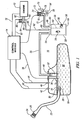
- Figure 1 is a schematic view, partly in cross section, of a vehicle fuel vapor control system for a plug-in hybrid vehicle.
- the system includes a fuel tank, fuel vapor line and a fuel vapor adsorbing canister with a purge line and solenoid-actuated valve and a vent line and solenoid-actuated valve.
- Figure 2 is a flow chart of an algorithm performed in a vehicle computer control module for fuel tank leak detection and determination of the RVP of the current tank fuel composition.
- a plug-in hybrid automotive vehicle has a suitable re-chargeable battery system that typically powers at least one electric motor for driving at least two wheels of the vehicle.
- a programmed computer is used to manage the operation of the electric motor and motive power delivered to the wheels in response to operator demand. While the battery system may be charged when the vehicle is not being driven, vehicle range even with a fully charged battery system is limited.
- an on-board gasoline powered engine is provided to power an electric generator to drive the electric motor when the battery reaches a low-charge condition.
- the focus of this invention and the following illustrations is on the fuel tank and evaporative emission control system for the plug-in hybrid vehicle gasoline engine.
- Fuel evaporative emission control systems have been in use on gasoline engine driven automotive vehicles for many years.
- the gasoline fuel used in many internal combustion engines is quite volatile and usually formulated to provide suitable seasonal volatility.
- the fuel typically consists of a hydrocarbon mixture ranging from high volatility butane (C-4) to lower volatility C-8 to C-10 hydrocarbons.
- C-4 high volatility butane
- C-8 lower volatility C-8 to C-10 hydrocarbons.
- daytime heating i.e., diurnal heating
- fuel temperature increases.
- the vapor pressure of the heated gasoline increases and fuel vapor will flow from any opening in the fuel tank.
- the tank is vented through a conduit to a canister containing suitable fuel adsorbent material.
- High surface area activated carbon granules are widely used to temporarily adsorb the fuel vapor.
- This invention adapts such a fuel evaporative emission control system for use in a plug-in hybrid vehicle.
- FIG. 1 An evaporative fuel emissions control system 10 for a plug-in hybrid automotive vehicle is illustrated in Figure 1 .
- the illustration is schematic and the components are not drawn to scale.
- the system comprises a multi-cylinder gasoline-powered internal combustion engine, schematically indicated at block 12, specified for powering an on-board electric generator (not shown).
- a modem fuel efficient, low exhaust and evaporative emissions engine is controlled using a suitable programmed digital microprocessor or computer control module.
- Such a control module indicated schematically at block 14, may be used in controlling engine operation and in controlling operation of the evaporative emission system. It may also be used in controlling operation of the battery system and electric motor drive.
- control module 14 which is powered by the vehicle battery (not shown), starts to receive signals from many sensors on the engine and emission control devices.
- Line 16 from the engine 12 to control module 14 schematically depicts the flow of such signals from the various sensors on the engine.
- gasoline is delivered from a fuel tank 18 by a fuel pump (not shown, but often located in the fuel tank) through a fuel line (not shown) to a fuel rail and fuel injectors that supply fuel to each cylinder of the engine or to ports that supply groups of cylinders.
- the timing of the operation of the fuel injectors and the amount of fuel injected per cylinder injection event is managed by control module 14.
- the subject emission control purge system is operated in harmony with engine operation to avoid upsetting the air-to-fuel ratio in the engine with a secondary flow of fuel-containing air.
- fuel tank 18 is closed except for a vent line 20.
- Tank 18 is suitably made of steel of a suitable thickness to contain tank pressures experienced during diurnal heating.
- the tank 18 is provided with fill tube 22 with a gas cap 24 closing the gas fill end 26.
- the outlet end 28 of fill tube 22 is inside tank 18 and is often provided with a one-way valve 30 to prevent liquid fuel from splashing out the fill tube 22.
- a volume of gasoline 32 is indicated with upper surface 34.
- a float-type fuel level indicator 36 provides a fuel level signal through line 38 to control module 14.
- Fuel tank pressure sensor 40 and temperature sensor 42 provide their respective data through signal transmitting lines 44 and 46, respectively, to control module 14.
- the sensors are used in this invention for diagnostic purposes. Sometimes both functions may be combined in a single sensor.
- Fuel tank 18 is provided with a vent line 20 that leads through seal 48 from the top of the tank to a fuel vapor adsorption canister 50.
- canister 50 is a refueling vapor recovery (ORVR) canister because, as will be described, it is primarily employed to recover fuel tank vapor during vehicle refueling.
- ORVR refueling vapor recovery
- Float valve 52 within the tank 18 prevents liquid gasoline from entering vapor vent line 20.
- fuel vapor mixed with air flows under fuel tank pressure through vent line 20 to the vapor inlet 54 of canister 50.
- the vapor enters canister vapor inlet 54 and diffuses into granular adsorptive carbon material 56.
- Canister 50 is typically molded of a suitable thermoplastic polymer such as nylon.
- canister 50 comprises four side walls, defining an internal volume of rectangular cross section (two side walls 58 shown), with an integral top 60 and a vertical internal partition 62 that extends from top 60 and the front and rear sides.
- Canister 50 includes a bottom closure 64 that is attached to the side walls. As shown, partition 62 extends toward but short of the bottom closure 64.
- a vapor vent opening 66 At the top of canister 50 is a vapor vent opening 66 that also serves as an inlet for the flow of air during the purging of adsorbed fuel vapor from the adsorbent material 56.
- canister 50 Also formed in the top 60 of the canister 50 is a purge outlet 68 through which a stream of purge air carrying purged fuel vapor can exit the canister. It is seen that the construction of canister 50 extends the flow path of vapor from vapor inlet 54 to vapor vent 66 because of the partition 62 and closed bottom 66.
- sealing valve 72 is closed when the vehicle is operated solely under battery power and when the vehicle is not operated (parked). Sealing valve 72 is opened by solenoid activation when engine 12 is running under conditions suitable to receive fuel vapor purged from canister 50. Sealing valve 72 is also opened when the vehicle is being refueled by the addition of gasoline to fuel tank 18. In its closed position the stopper portion 76 of sealing valve 72 is biased closed to cover vent opening 78 in vapor vent/air inlet line 70. Upon actuation of battery-powered solenoid 74, stopper 76 is moved to uncover vent opening 78.
- Solenoid 74 is actuated upon command of control module 14 through signal lead 80.
- the vent valve 72 is usually only opened during vehicle refueling and during suitable modes of engine operation.
- a by-pass line 94 around vent opening 78 with a pressure/vacuum relief valve 96 may be used to protect fuel tank 18 from unexpectedly high pressure or vacuum when vent opening is closed by stopper 76.
- Tank protection relief valve 96 opens when, for example, the pressure in fuel tank 18 exceeds 3.5 psi or -2.0 psi (vacuum).
- Canister purge outlet 68 is connected by purge line 82 through solenoid-actuated purge valve 84 to the engine 12.
- Purge valve 84 includes a battery-powered solenoid 86 and stopper 88 to close purge opening 90. Purge valve 84 is closed at engine-off and is opened only by command of control module 14 through signal lead 92 when the engine 12 is running and can accommodate the secondary stream of fuel-laden air stream drawn through canister 50.
- vent valve 72 and purge valve 84 are open. Air enters vapor vent/air inlet line 70 and flows through the volume of carbon granules on both the right side and left side of partition 62 and exits through canister purge outlet 68. The flow of air carries hydrocarbon vapor removed from the surfaces of carbon granules 56 through purge line 82 to engine 12. Depending upon ambient conditions, fuel vapor may also be flowing from fuel tank 18 through vent line 20 and vent inlet 54 of canister 50. Since the vapor inlet 54 is spaced from purge outlet 68, the vapor can enter the canister but will be removed by the counter flow of air. Thus, during engine operation much of the fuel vapor temporarily stored in canister 50 during tank 18 refueling is removed to provide adsorption capacity for vapor generated during the next fuel tank refueling period.
- sealing valve 72 When the plug-in hybrid vehicle is being refueled sealing valve 72 is opened to permit fuel vapor to flow from fuel tank 18 through vent line 20 to canister 50.
- the canister's vapor vent/air inlet line 70 and purge line 82 are closed during many periods of vehicle soak. During such periods the pressure in fuel tank 18, vent line 20, canister, 50 etc. may increase substantially during diurnal heating, but no diurnal vapor is released from the tank. And the closure of valves 72, 84 prevents bleeding of fuel vapor from the canister if it had already contained substantial amount of fuel vapor. It is noted that fuel tank 18 can be sealed to prevent diurnal vapor generation by installing a solenoid actuated closing valve in vapor line 20 instead of using valve 72. However, such system will not prevent bleeding of fuel vapor emissions from canister 50.
- control module 14 may run diagnostic tests of many systems of the vehicle.
- control module 14 is programmed to test for leaks in fuel tank 18 and to determine RVP of fuel than in tank 18.
- Plug-in vehicle fuel tank pressure may be monitored using an electronic pressure sensor (40 in Figure 1 ).
- the tank temperature can be monitored using a thermister 42 or it can be estimated from the vehicle ambient temperature sensor. Knowing tank pressure change ⁇ P for known temperature change from T1 to T2, the fuel RVP can be predicted as described below.
- P g ⁇ 1 A . T ⁇ 1.
- FIG. 2 is a flow chart showing how a vehicle control module 14 may be programmed to detect a fuel tank leak and to estimate tank fuel RVP by measuring tank temperatures and pressure/vacuum (e.g., sensors 42, 40).
- tank leak detection as a part onboard diagnostics (OBD II) and tank fuel RVP (Reid Vapor Pressure) detection is useful for engine cold start, driveability, and monitoring weathering of unused tank fuel.
- OBD II onboard diagnostics
- RVP Reid Vapor Pressure
- Example 2 Gasoline fuel tank temperature increases from 74.2°F (296.6 °K) to 92.0°F (306.5 °K), which results in tank pressure of 2.52 psig.
- the change in estimated RVP from Iteration 2 to Iteration 3 was insignificant (0.04 psi); therefore, there is no need to iterate any further.
- the estimated RVP is 8.84 psi which compares very well with the measured value of 9 psi. Note that the measured value of RVP is accurate with in ⁇ 0.2 psi. Therefore, the equation developed in this work can be used for predicting the plug-in hybrid tank fuel RVP from the tank pressure increase for known temperature increase.
- FIG. 2 shows a flow chart which illustrates how the vehicle computer can check for the leaks in the tank (onboard diagnostics) and also predict tank fuel RVP. This leak detection system eliminates the need for additional hardware.
- a suitably programmed computer module 14 reads fuel tank temperature T2 and pressure P2 at engine startup.
- values T2 and P2 are compared with previously stored temperature and pressure values T1 and P1.
- Values T1 and P1 are suitable values stared in the control module at the previous vehicle shut down.
- Step 104 is a query step in which it is determined whether T2-T1 is greater than zero. If the answer to query 104 is "no" (step 106) conditions are not suitable for a leak check or a determination of RVP and the process is stopped until the next occasion of a vehicle start-up.
- step 108 the control module determines whether P2-P1 is greater than zero (query step 108 in Figure 2 ). If the answer is "no" (step 110) it is determined that there is a leak in the fuel tank, or its vent line, or the canister purge line. If the answer in query step 108 is "yes', no leak has been detected by this process and the process continues to step 112 in which the RVP of the current vehicle fuel is estimated. RVP is estimated using the equation and values for constants A and B set forth in Figure 2 (and as illustrated above). After step 112, the process is completed except for storing new values of current fuel tank temperature (T1) and pressure (PI) when the vehicle is shut down.
- T1 current fuel tank temperature
- PI pressure
- the vehicle control module can alert the operator for fuel change or implement forced use of the fuel before further weathering can occur and cause engine operational problems (poor cold start and driveability). If the predicted RVP is too high (winter fuel carried over to summer), the vehicle computer can alert the operator about excessive tank pressures and/or uncontrolled vapor emissions into the atmosphere by opening the tank pressure relief valve.
- This invention provides a method of operating a fuel evaporative emission control system in a plug-in hybrid vehicle driven by a battery powered electric motor with a supplemental gasoline powered-electric generator operated on demand for supplemental electric power for the vehicle.
- the system is sealed when the engine is not operating and when the vehicle is not being refueled to minimize vapor generation in the fuel tank due to diurnal heating and to eliminate bleeding of fuel vapor from the canister system.
Description
- This invention pertains to the management of fuel tank gasoline vapor produced in operation of battery powered, electric motor driven automotive vehicles having a gasoline engine for generating supplemental electrical power on extended driving trips. The evaporative emission management process also enables periodic testing for fuel tank leaks and for assessment of the current Reid Vapor Pressure of on-board fuel.
-
US 2006/053868 A1 discloses a method of operating a fuel evaporative emission control system in a hybrid powered vehicle, driven by an internal combustion engine and by a battery powered electric motor with a supplemental electric generator, operated on-demand by said internal combustion engine for supplemental electric power for the vehicle, the vehicle comprising a fuel tank, a fuel vapor vent passage from the fuel tank to a fuel adsorption canister, a first normally open air and fuel vapor flow passage from the canister for venting the canister and for introduction of purge air to the canister to purge fuel vapor from the canister, and a second normally closed air and fuel vapor flow passage from the canister for passage of purge air and purged fuel vapor from the canister to an air induction system of the engine, the method comprising maintaining open the first and opening the second air and fuel vapor passages during engine operation and closing the first and opening the second air and fuel vapor passages while the engine is not running but being spinned by an electric motor in order to draw a vacuum within the vapor control system to determine if a leak in the control system may exist. Document D1 is silent about whether the two air and fuel vapor passages are open or closed when the vehicle is not operating and/or is refueled or when the engine is not operated but the vehicle is in operation.
US 2004/0231404 A1 , discloses a failure diagnosis apparatus for diagnosing a failure of a evaporative fuel processing system and a control system for an internal combustion engine, in particular a watercraft propulsion engine, but not for an hybrid vehicle drive. A fuel tank is connected through a charging passage to a canister. The canister is connected through a purging passage to an intake pipe of the internal combustion engine. The purging passage is provided with a solenoid purge control valve which is closed when powered off by turning off an ignition switch. The canister is connected furthermore to the atmosphere via a vent passage which is provided with a solenoid vent shut valve which is open during refueling or when the evaporative fuel, adsorbed in the canister, is purged to the intake pipe. Thus the vent shut valve is normally open and remains open when no drive signal is applied thereto. When a pressure in the evaporative fuel processing system is to be detected, the purge control valve and the vent shut valve are closed when stoppage of the engine is detected. It follows that the purge control valve in the purging passage and the vent shut valve in the vent passage are closed when stoppage of the engine is detected and the failure diagnosis is executed. Document D2 is silent about whether the two air and fuel vapor passages are opened or closed when the engine is not operating and/or is refueled or when the engine is not operating during extending periods. - There is interest in producing passenger vehicles driven by an electric motor powered by a re-chargeable battery (for example, a lithium-ion battery). The operating range of the battery powered vehicle would be increased using an on-board electric generator driven, upon demand, by a gasoline engine. For relatively short driving excursions, the capacity of the battery would suffice and the gasoline engine would not be started. At the completion of such trips the battery would be recharged from a 110 volt AC source. Such a vehicle is sometimes called a plug-in hybrid vehicle.
- Since many local driving trips could be completed within the electrical power capacity of the battery it is anticipated that many days could pass without starting the gasoline engine. But the engine would be necessary when longer trips are taken. By way of example, it is contemplated that battery-only trips (before plug-in recharging) may be of up to about forty miles. But the gasoline engine-driven electric generator would be used to increase the range of the vehicle to several hundred miles.
- Despite its intermittent usage the plug-in hybrid gasoline engine will, of course, require on-board fuel storage. Gasoline stored in a vehicle fuel tank is exposed to ambient heating which increases the vapor pressure of the volatile hydrocarbon fuel. In conventional gasoline powered engines fuel tank vapor (typically comprising lower molecular weight hydrocarbons) is vented to a canister containing high surface area carbon granules for temporary adsorption of fuel tank emissions. Later, during engine operation ambient air is drawn through the carbon granule bed to purge adsorbed fuel from the surfaces of the carbon particles and carry the removed fuel into the air induction system of the vehicle engine. As stated, such plug-in hybrid vehicles operate mostly on batteries which are charged during the night by plugging into home AC outlets. A plug-in hybrid vehicle IC engine may not run for several days which results in no purging (cleaning) of the evaporative emission control canister. However, a conventional fuel tank will be generating diurnal vapors everyday. It would be desirable to use the familiar canisters but the mode of their operation must be altered to contain fuel vapor tending to flow from the fuel tank. This invention makes use of a familiar fuel evaporative emission control canister in a method of operation adapted for a plug-in hybrid type vehicle.
- This invention provides a method of operating a fuel storage and delivery system for a plug-in hybrid type vehicle. The vehicle has a fuel storage and delivery system for operation of a gasoline engine that operates on demand for powering a generator for recharging a vehicle battery system and for providing supplemental electrical power for the electric motor or motors driving the wheels of the vehicle. In order to meet federal and state evaporative emission standards it is necessary to devise and operate a fuel storage and delivery system that releases little or no fuel from the vehicle at any time.
- In accordance with one environment, a fuel tank is provided for a gasoline-fueled engine specified for on-demand powering of a generator for a plug-in hybrid vehicle. The tank has a filler pipe with a closure for refueling, a fuel pump and fuel line for delivery of fuel to the engine. The tank has sensors for detecting fuel level, fuel temperature and fuel tank pressure. And the tank has a fuel vapor vent line leading from the tank to the vapor inlet of an on-board refueling vapor recovery (ORVR) canister. The ORVR canister has an air inlet line for purging the canister of adsorbed fuel vapor during the periodic on-demand engine operation. The ORVR canister also has an outlet line for conduct of airborne fuel vapor drawn from the canister to the air intake system of the gasoline engine. Flow in each of the air inlet purge line and canister outlet purge line are controlled by suitable valves which may be electrical solenoid actuated valves. A computer control module (which may also be controlling other engine or vehicle functions) receives fuel level and fuel tank pressure input in controlling the operation of the control valves. The air inlet purge line may have a pressure/vacuum relief line and valve around the control valve in the air inlet line.
- In a representative embodiment of the invention, the solenoid valves (or other suitable valves) in both control lines are closed except during fuel tank refueling and engine operation. Thus, the fuel tank and its ORVR canister are sealed shut with respect to venting of fuel vapor except for canister purging during engine operation and subsequent fuel tank venting and canister loading during refueling of the vehicle. Diurnal fuel temperature and pressure fluctuations are contained by the sealed system with some canister loading during fuel temperature and tank pressure increases and some canister unloading to the tank during fuel temperature and pressure decreases. The pressure/vacuum relief valve and line accommodates abnormal fluctuations in fuel tank pressure or vacuum. Thus, fuel vapor is contained within this sealed plug-in hybrid fuel system preventing canister fuel vapor bleed emissions.
- In another embodiment of the invention, provision is made for periodic control module testing for leakage from the fuel system and for determining the Reid Vapor Pressure (RVP) value of the contained fuel for controlled engine operation. The sealed fuel tank system provides an opportunity to use fuel tank pressure increase/decrease for detecting fuel system leaks and for determining tank fuel RVP. Environmental Protection Agency (EPA) and California Air Resource Board (CARB) regulations require tank leak detection as a part of onboard diagnostics (OBD II). Tank fuel RVP determination is useful for engine cold start, driveability, and monitoring weathering of unused tank fuel. The vehicle computer control module has stored and incoming temperature and pressure data from sensors in the fuel tank and uses this data for periodic tests for leakage and RVP calculations.
- Fuel vapor leakage from the fuel system is detected when a measured increase in fuel temperature fails to produce a corresponding increase in fuel tank pressure. Similarly RVP may be calculated using an algorithm stored in the control module.
- These and other objects and advantages of the invention will be further understood following a more detailed description of preferred embodiments of the invention.
-
Figure 1 is a schematic view, partly in cross section, of a vehicle fuel vapor control system for a plug-in hybrid vehicle. The system includes a fuel tank, fuel vapor line and a fuel vapor adsorbing canister with a purge line and solenoid-actuated valve and a vent line and solenoid-actuated valve. -
Figure 2 is a flow chart of an algorithm performed in a vehicle computer control module for fuel tank leak detection and determination of the RVP of the current tank fuel composition. - A plug-in hybrid automotive vehicle has a suitable re-chargeable battery system that typically powers at least one electric motor for driving at least two wheels of the vehicle. As the vehicle operator drives the vehicle, a programmed computer is used to manage the operation of the electric motor and motive power delivered to the wheels in response to operator demand. While the battery system may be charged when the vehicle is not being driven, vehicle range even with a fully charged battery system is limited. In the subject hybrid electric motor-powered vehicle, an on-board gasoline powered engine is provided to power an electric generator to drive the electric motor when the battery reaches a low-charge condition. The focus of this invention and the following illustrations is on the fuel tank and evaporative emission control system for the plug-in hybrid vehicle gasoline engine.
- Fuel evaporative emission control systems have been in use on gasoline engine driven automotive vehicles for many years. The gasoline fuel used in many internal combustion engines is quite volatile and usually formulated to provide suitable seasonal volatility. The fuel typically consists of a hydrocarbon mixture ranging from high volatility butane (C-4) to lower volatility C-8 to C-10 hydrocarbons. During daytime heating (i.e., diurnal heating), fuel temperature increases. The vapor pressure of the heated gasoline increases and fuel vapor will flow from any opening in the fuel tank. Normally, to prevent vapor loss into the atmosphere, the tank is vented through a conduit to a canister containing suitable fuel adsorbent material. High surface area activated carbon granules are widely used to temporarily adsorb the fuel vapor. This invention adapts such a fuel evaporative emission control system for use in a plug-in hybrid vehicle.
- An evaporative fuel emissions control
system 10 for a plug-in hybrid automotive vehicle is illustrated inFigure 1 . The illustration is schematic and the components are not drawn to scale. - The system comprises a multi-cylinder gasoline-powered internal combustion engine, schematically indicated at
block 12, specified for powering an on-board electric generator (not shown). The operation of a modem fuel efficient, low exhaust and evaporative emissions engine is controlled using a suitable programmed digital microprocessor or computer control module. Such a control module, indicated schematically atblock 14, may be used in controlling engine operation and in controlling operation of the evaporative emission system. It may also be used in controlling operation of the battery system and electric motor drive. - When the gasoline engine is started,
control module 14, which is powered by the vehicle battery (not shown), starts to receive signals from many sensors on the engine and emission control devices.Line 16 from theengine 12 to controlmodule 14 schematically depicts the flow of such signals from the various sensors on the engine. During engine operation, gasoline is delivered from afuel tank 18 by a fuel pump (not shown, but often located in the fuel tank) through a fuel line (not shown) to a fuel rail and fuel injectors that supply fuel to each cylinder of the engine or to ports that supply groups of cylinders. The timing of the operation of the fuel injectors and the amount of fuel injected per cylinder injection event is managed bycontrol module 14. The subject emission control purge system is operated in harmony with engine operation to avoid upsetting the air-to-fuel ratio in the engine with a secondary flow of fuel-containing air. - Since gasoline and other fuels are quite volatile,
fuel tank 18 is closed except for avent line 20.Tank 18 is suitably made of steel of a suitable thickness to contain tank pressures experienced during diurnal heating. Thetank 18 is provided withfill tube 22 with agas cap 24 closing the gas fillend 26. Theoutlet end 28 offill tube 22 is insidetank 18 and is often provided with a one-way valve 30 to prevent liquid fuel from splashing out thefill tube 22. - A volume of
gasoline 32 is indicated withupper surface 34. A float-typefuel level indicator 36 provides a fuel level signal throughline 38 to controlmodule 14. Fueltank pressure sensor 40 andtemperature sensor 42 provide their respective data throughsignal transmitting lines module 14. The sensors are used in this invention for diagnostic purposes. Sometimes both functions may be combined in a single sensor. -
Fuel tank 18 is provided with avent line 20 that leads throughseal 48 from the top of the tank to a fuelvapor adsorption canister 50. In this system,canister 50 is a refueling vapor recovery (ORVR) canister because, as will be described, it is primarily employed to recover fuel tank vapor during vehicle refueling. -
Float valve 52 within thetank 18 prevents liquid gasoline from enteringvapor vent line 20. During refueling, fuel vapor mixed with air (often moisture containing air) flows under fuel tank pressure throughvent line 20 to thevapor inlet 54 ofcanister 50. The vapor enterscanister vapor inlet 54 and diffuses into granularadsorptive carbon material 56. -
Canister 50 is typically molded of a suitable thermoplastic polymer such as nylon. In this embodiment,canister 50 comprises four side walls, defining an internal volume of rectangular cross section (twoside walls 58 shown), with an integral top 60 and a verticalinternal partition 62 that extends from top 60 and the front and rear sides.Canister 50 includes abottom closure 64 that is attached to the side walls. As shown,partition 62 extends toward but short of thebottom closure 64. At the top ofcanister 50 is a vapor vent opening 66 that also serves as an inlet for the flow of air during the purging of adsorbed fuel vapor from theadsorbent material 56. Also formed in the top 60 of thecanister 50 is apurge outlet 68 through which a stream of purge air carrying purged fuel vapor can exit the canister. It is seen that the construction ofcanister 50 extends the flow path of vapor fromvapor inlet 54 tovapor vent 66 because of thepartition 62 and closed bottom 66. - Connected to vent
opening 66 is a vapor vent/air inlet line 70 and solenoid-actuatedsealing valve 72. In accordance with this invention, sealingvalve 72 is closed when the vehicle is operated solely under battery power and when the vehicle is not operated (parked). Sealingvalve 72 is opened by solenoid activation whenengine 12 is running under conditions suitable to receive fuel vapor purged fromcanister 50. Sealingvalve 72 is also opened when the vehicle is being refueled by the addition of gasoline tofuel tank 18. In its closed position thestopper portion 76 of sealingvalve 72 is biased closed to covervent opening 78 in vapor vent/air inlet line 70. Upon actuation of battery-poweredsolenoid 74,stopper 76 is moved to uncovervent opening 78.Solenoid 74 is actuated upon command ofcontrol module 14 throughsignal lead 80. As stated, thevent valve 72 is usually only opened during vehicle refueling and during suitable modes of engine operation. However, a by-pass line 94 around vent opening 78 with a pressure/vacuum relief valve 96 may be used to protectfuel tank 18 from unexpectedly high pressure or vacuum when vent opening is closed bystopper 76. Tankprotection relief valve 96 opens when, for example, the pressure infuel tank 18 exceeds 3.5 psi or -2.0 psi (vacuum). -
Canister purge outlet 68 is connected bypurge line 82 through solenoid-actuatedpurge valve 84 to theengine 12.Purge valve 84 includes a battery-poweredsolenoid 86 andstopper 88 to closepurge opening 90.Purge valve 84 is closed at engine-off and is opened only by command ofcontrol module 14 throughsignal lead 92 when theengine 12 is running and can accommodate the secondary stream of fuel-laden air stream drawn throughcanister 50. - As stated above, during suitable periods of engine-on operation, when the engine can accommodate purged fuel vapor in its air inlet, both vent
valve 72 andpurge valve 84 are open. Air enters vapor vent/air inlet line 70 and flows through the volume of carbon granules on both the right side and left side ofpartition 62 and exits throughcanister purge outlet 68. The flow of air carries hydrocarbon vapor removed from the surfaces ofcarbon granules 56 throughpurge line 82 toengine 12. Depending upon ambient conditions, fuel vapor may also be flowing fromfuel tank 18 throughvent line 20 and ventinlet 54 ofcanister 50. Since thevapor inlet 54 is spaced frompurge outlet 68, the vapor can enter the canister but will be removed by the counter flow of air. Thus, during engine operation much of the fuel vapor temporarily stored incanister 50 duringtank 18 refueling is removed to provide adsorption capacity for vapor generated during the next fuel tank refueling period. - When the plug-in hybrid vehicle is being refueled sealing
valve 72 is opened to permit fuel vapor to flow fromfuel tank 18 throughvent line 20 tocanister 50. - Thus, the canister's vapor vent/
air inlet line 70 andpurge line 82 are closed during many periods of vehicle soak. During such periods the pressure infuel tank 18,vent line 20, canister, 50 etc. may increase substantially during diurnal heating, but no diurnal vapor is released from the tank. And the closure ofvalves fuel tank 18 can be sealed to prevent diurnal vapor generation by installing a solenoid actuated closing valve invapor line 20 instead of usingvalve 72. However, such system will not prevent bleeding of fuel vapor emissions fromcanister 50. - During suitable periods of vehicle operation the
control module 14 may run diagnostic tests of many systems of the vehicle. In accordance with an embodiment of this invention,control module 14 is programmed to test for leaks infuel tank 18 and to determine RVP of fuel than intank 18. - Plug-in vehicle fuel tank pressure may be monitored using an electronic pressure sensor (40 in
Figure 1 ). The tank temperature can be monitored using athermister 42 or it can be estimated from the vehicle ambient temperature sensor. Knowing tank pressure change ΔP for known temperature change from T1 to T2, the fuel RVP can be predicted as described below. - By previous analysis, gasoline vapor pressure is found to be related to its temperature in accordance with the following equation which may be used in
control module 14.
where Pg is gasoline vapor pressure (psi) at temperature T (°K); A and B are constants 25.61, 2789.78, respectively; and RVP is Reid Vapor Pressure (psi).
Solving Equation (1) for P
Simplifying Equation (2) results in
- Equation (3) can be used to estimate gasoline vapor pressure increase ΔPg for temperature increase from T1 to T2

- The pressure increase measured in a sealed gasoline tank Δ P is due to gasoline vapor pressure increase ΔPg and also due to thermal expansion of air in the headspace ΔPt :

- An equation can be derived for ΔPt by using ideal gas law for constant volume:

where Pa 1 and Pa 2 headspace air partial pressures corresponding to temperatures T1 and T2, respectively. Equation (6) can be written as:
- If the initial tank pressure is equal to atmospheric pressure Patm , the initial partial pressure of air Pa 1 is equal to Patm - Pg 1; therefore, Equation (7) can be written as:

where Pg 1 is estimated by using Equation (3) as shown below and atmospheric pressure can be assumed to be 14.7 psi if actual value is not available.
- Plug-in hybrid sealed fuel tank offers an opportunity to use the tank pressure increase/decrease for detecting tank leaks and tank fuel RVP.
Figure 2 is a flow chart showing how avehicle control module 14 may be programmed to detect a fuel tank leak and to estimate tank fuel RVP by measuring tank temperatures and pressure/vacuum (e.g.,sensors 42, 40). As stated, CARB and EPA regulations require tank leak detection as a part onboard diagnostics (OBD II) and tank fuel RVP (Reid Vapor Pressure) detection is useful for engine cold start, driveability, and monitoring weathering of unused tank fuel. - Knowing tank pressure change Δ P for known temperature change from T1 to T2, the fuel RVP can be predicted by using the following equations.
Equation (4) can be rewritten as:
Equation (5) can be rewritten as:
- Where ΔP is measured and ΔPt needs to be estimated using Equation (8); however, Pg 1 is not known. An iterative process has to be used; in first iteration, we have to assume Pg =0 and rewrite Equation (8):

- In the second iteration, one uses the RVP estimated from the first iteration to estimate Pg 1 and then more accurate value of RVP. The iterative RVP estimation can be illustrated by an example as shown below.
Example: Gasoline fuel tank temperature increases from 74.2°F (296.6 °K) to 92.0°F (306.5 °K), which results in tank pressure of 2.52 psig. - Iteration 1:
- From Equation (8a) ΔPt =(14.7*306.5/296.6)-14.7 = 0.49 psig
From Equation (5a) ΔPg = 2.52-0.49 = 2.03 psig
From Equation (10) RVP = 8.12 psi - Iteration 2:
- From Equation (9) Pg 1 = 5.07 psi
From Equation (8) ΔPt =(14.7-5.07)*(306.5/296.6) - (14.7-5.07) = 0.32 psig
From Equation (5a) ΔPg = 2.52-0.32 = 2.20 psig
From Equation (10) RVP = 8.80 psi - Iteration 3:
- From Equation (9) Pg 1 = 5.50 psi
From Equation (8) ΔPt = 14.7-5.50)*(306.5/296.6) - (14.7-5.50) = 0.31 psig
From Equation (5a) ΔPg = 2.52-0.31 = 2.21 psig
From Equation (10) RVP = 8.84 psi - The change in estimated RVP from Iteration 2 to Iteration 3 was insignificant (0.04 psi); therefore, there is no need to iterate any further. The estimated RVP is 8.84 psi which compares very well with the measured value of 9 psi. Note that the measured value of RVP is accurate with in ±0.2 psi. Therefore, the equation developed in this work can be used for predicting the plug-in hybrid tank fuel RVP from the tank pressure increase for known temperature increase.
-
Figure 2 shows a flow chart which illustrates how the vehicle computer can check for the leaks in the tank (onboard diagnostics) and also predict tank fuel RVP. This leak detection system eliminates the need for additional hardware. - In
Figure 2 , atstep 100, a suitably programmedcomputer module 14 reads fuel tank temperature T2 and pressure P2 at engine startup. Instep 102, values T2 and P2 are compared with previously stored temperature and pressure values T1 and P1. Values T1 and P1 are suitable values stared in the control module at the previous vehicle shut down. - The stored values are subtracted from currently read values, T2-T1 and P2-P1. Step 104 is a query step in which it is determined whether T2-T1 is greater than zero. If the answer to query 104 is "no" (step 106) conditions are not suitable for a leak check or a determination of RVP and the process is stopped until the next occasion of a vehicle start-up.
- If the answer to query 104 is "yes", the control module determines whether P2-P1 is greater than zero (
query step 108 inFigure 2 ). If the answer is "no" (step 110) it is determined that there is a leak in the fuel tank, or its vent line, or the canister purge line. If the answer inquery step 108 is "yes', no leak has been detected by this process and the process continues to step 112 in which the RVP of the current vehicle fuel is estimated. RVP is estimated using the equation and values for constants A and B set forth inFigure 2 (and as illustrated above). Afterstep 112, the process is completed except for storing new values of current fuel tank temperature (T1) and pressure (PI) when the vehicle is shut down. - If a RVP determination reveals that the value is too low due to fuel weathering, the vehicle control module can alert the operator for fuel change or implement forced use of the fuel before further weathering can occur and cause engine operational problems (poor cold start and driveability). If the predicted RVP is too high (winter fuel carried over to summer), the vehicle computer can alert the operator about excessive tank pressures and/or uncontrolled vapor emissions into the atmosphere by opening the tank pressure relief valve.
- This invention provides a method of operating a fuel evaporative emission control system in a plug-in hybrid vehicle driven by a battery powered electric motor with a supplemental gasoline powered-electric generator operated on demand for supplemental electric power for the vehicle. The system is sealed when the engine is not operating and when the vehicle is not being refueled to minimize vapor generation in the fuel tank due to diurnal heating and to eliminate bleeding of fuel vapor from the canister system.
- While embodiments of the invention have been illustrated, these illustrations are not intended to limit the scope of the invention as defined by the appendant claims.
Claims (8)
- A method of operating a fuel evaporative emission control system (10) in a plug-in hybrid vehicle driven by a battery powered electric motor A with a supplemental gasoline engine (12) powered-electric generator operated on-demand for supplemental electric power for the vehicle, where the vehicle comprises a gasoline fuel tank (18), a fuel vapor vent passage (20) from the fuel tank (18) to a fuel vapor adsorption canister (50), a first air and fuel vapor flow passage (70) from the canister (50) for venting the canister (50) and for introduction of purge air to the canister (50) to purge fuel vapor from the canister (50), and a second air and fuel vapor flow passage (82) from the canister (50) for passage of purge air and purged fuel vapor from the canister (50) to an air induction system of the engine (12); the method comprising:opening the first (70) and second (82) air and fuel vapor passages during engine operation;opening the first air and fuel vapor passage (70), but not the second air and fuel flow passage (82), when the vehicle is not operating and the gasoline is being added to the fuel tank (18); andclosing both of the first (70) and second (82) air and fuel vapor passages for preventing diurnal vapor generation and preventing bleeding of fuel vapor from the canister (50) when the vehicle is not in operation and when the vehicle is in operation but the gasoline engine (12) is not being operated.
- A method of operating a fuel evaporative emission control system (10) as recited in claim 1 in which the opening and the closure of the first (70) and second (82) air and fuel vapor passages is controlled by signal of a computer control module (14).
- A method of operating a fuel evaporative emission control system (10) as recited in claim 1 in which the opening and closure of the first (70) and second (82) air and fuel vapor passages is performed by an electric solenoid valve (72, 84) in each passage.
- A method of operating a fuel evaporative emission control system (10) as recited in claim 1 in which the passage of air and vapor in the first (70) and second air (82) and fuel vapor flow passages is controlled by an electric solenoid valve (72, 84) in each passage and the respective solenoid valves (72, 84) are operated by signal of a computer control module (14).
- A method of operating a fuel evaporative emission control system (10) as recited in claim 1 in which the vehicle comprises a computer control module (14) for operation of the evaporative emission control system (10) and the control module (14) acquires temperature and pressure data of the fuel in the fuel tank (18) at predetermined times during vehicle operation.
- A method of operating a fuel evaporative emission control system (10) as recited in claim 5 in which the control module (14) compares fuel temperatures and fuel tank pressures taken at a first time and at a second later time to determine whether there is a fuel vapor leak from the fuel tank (18) or canister (50).
- A method of operating a fuel evaporative emission control system (10) as recited in claim 6 in which in which the first time is at an occasion of vehicle shut down and the second time is the next occasion of vehicle start.
- A method of operating a fuel evaporative emission control system (10) as recited in claim 5 in which the control module (14) compares fuel temperatures and fuel pressures taken at a first time and at a second later time to determine the Reid Vapor Pressure of the fuel then in the fuel tank (18).
Applications Claiming Priority (1)
| Application Number | Priority Date | Filing Date | Title |
|---|---|---|---|
| US11/777,373 US7448367B1 (en) | 2007-07-13 | 2007-07-13 | Evaporative emission control in battery powered vehicle with gasoline engine powered generator |
Publications (3)
| Publication Number | Publication Date |
|---|---|
| EP2014904A2 EP2014904A2 (en) | 2009-01-14 |
| EP2014904A3 EP2014904A3 (en) | 2010-12-29 |
| EP2014904B1 true EP2014904B1 (en) | 2012-12-26 |
Family
ID=39855492
Family Applications (1)
| Application Number | Title | Priority Date | Filing Date |
|---|---|---|---|
| EP08012618A Revoked EP2014904B1 (en) | 2007-07-13 | 2008-07-11 | Evaporative emission control in battery powered vehicle with gasoline engine powered generator |
Country Status (4)
| Country | Link |
|---|---|
| US (1) | US7448367B1 (en) |
| EP (1) | EP2014904B1 (en) |
| KR (1) | KR101029143B1 (en) |
| CN (1) | CN101344054B (en) |
Cited By (1)
| Publication number | Priority date | Publication date | Assignee | Title |
|---|---|---|---|---|
| CN106170683A (en) * | 2014-04-04 | 2016-11-30 | 全耐塑料高级创新研究公司 | Vehicle liquid containment system and method of verifying integrity thereof |
Families Citing this family (57)
| Publication number | Priority date | Publication date | Assignee | Title |
|---|---|---|---|---|
| DE102007058197B4 (en) * | 2007-12-04 | 2017-12-28 | Dr. Ing. H.C. F. Porsche Aktiengesellschaft | hybrid vehicle |
| US8118009B2 (en) * | 2007-12-12 | 2012-02-21 | Ford Global Technologies, Llc | On-board fuel vapor separation for multi-fuel vehicle |
| DE102008039300A1 (en) * | 2008-08-22 | 2010-03-04 | Audi Ag | Fuel tank firmness testing method for use in internal combustion engine of motor vehicle, involves testing opening characteristics of pressure switch for diagnosing operability of pressure switch after turning off of combustion engine |
| US20100126477A1 (en) * | 2008-11-21 | 2010-05-27 | Gm Global Technology Operations, Inc. | Evaporative emissions control system |
| US8495988B2 (en) * | 2009-04-07 | 2013-07-30 | GM Global Technology Operations LLC | Fuel storage and vapor recovery system |
| US8584704B2 (en) * | 2009-04-22 | 2013-11-19 | Eaton Corporation | Valve assembly for high-pressure fluid reservoir |
| US8573255B2 (en) | 2009-04-22 | 2013-11-05 | Eaton Corporation | Valve assembly for high-pressure fluid reservoir |
| USD706389S1 (en) | 2010-03-30 | 2014-06-03 | Eaton Corporation | Fuel tank isolation valve |
| US9371803B2 (en) | 2009-04-22 | 2016-06-21 | Eaton Corporation | Valve assembly |
| JP2011021505A (en) * | 2009-07-14 | 2011-02-03 | Aisan Industry Co Ltd | Evaporated fuel processing device |
| DE102009057227B4 (en) * | 2009-12-05 | 2016-09-01 | Avl Software And Functions Gmbh | Method of operating a fuel system |
| US8944100B2 (en) | 2010-03-30 | 2015-02-03 | Eaton Corporation | Isolation valve with fast depressurization for high-pressure fuel tank |
| USD706390S1 (en) | 2010-03-30 | 2014-06-03 | Eaton Corporation | Fuel tank isolation valve |
| USD829304S1 (en) | 2010-03-30 | 2018-09-25 | Eaton Intelligent Power Limited | Valve carriage |
| US9500291B2 (en) | 2010-03-30 | 2016-11-22 | Eaton Corporation | Isolation valve with fast depressurization for high-pressure fuel tank |
| DE102010053994A1 (en) | 2010-07-19 | 2012-01-19 | Kautex Textron Gmbh & Co. Kg | Fuel tank for a motor vehicle |
| US8346424B2 (en) * | 2010-09-20 | 2013-01-01 | GM Global Technology Operations LLC | Method of monitoring in-use performance ratios of onboard diagnostic systems for plug-in hybrid electric vehicles |
| EP2619435A4 (en) | 2010-09-24 | 2017-03-29 | Karma Automotive LLC | System for evaporative and refueling emission control for a vehicle |
| KR101197453B1 (en) * | 2010-09-29 | 2012-11-05 | 현대자동차주식회사 | Fuel tank valve structure of hybrid car controlling emission gas |
| JP2012149592A (en) * | 2011-01-20 | 2012-08-09 | Toyota Motor Corp | Evaporation system leakage diagnostic apparatus |
| US8560167B2 (en) | 2011-02-18 | 2013-10-15 | Ford Global Technologies, Llc | System and method for performing evaporative leak diagnostics in a vehicle |
| EP2537697A1 (en) | 2011-06-21 | 2012-12-26 | Inergy Automotive Systems Research (Société Anonyme) | Ventilation device for fuel system of hybrid vehicle |
| JP5333532B2 (en) * | 2011-07-14 | 2013-11-06 | 株式会社デンソー | Fuel vapor leak detection device |
| US8689613B2 (en) * | 2011-09-28 | 2014-04-08 | Continental Automotive Systems, Inc. | Leak detection method and system for a high pressure automotive fuel tank |
| DE102011086221A1 (en) * | 2011-11-11 | 2013-05-16 | Robert Bosch Gmbh | Optimization of tank ventilation of a fuel tank |
| US8746215B2 (en) * | 2011-12-02 | 2014-06-10 | Continental Automotive Systems, Inc. | Sample tube structure for automotive fuel tank leak detection |
| US8881710B2 (en) | 2012-05-02 | 2014-11-11 | Ford Global Technologies, Llc | Bleed element with overmolded seal for evaporative emissions canister |
| EP2666997A1 (en) | 2012-05-25 | 2013-11-27 | Inergy Automotive Systems Research (Société Anonyme) | Method for detecting a presence or absence of a leak in a fuel system |
| EP2667008A1 (en) | 2012-05-25 | 2013-11-27 | Inergy Automotive Systems Research (Société Anonyme) | Method and System for Detecting a Leak in a Fuel System |
| US9376991B2 (en) * | 2012-07-24 | 2016-06-28 | Ford Global Technologies, Llc | Passive venturi pump for leak diagnostics and refueling |
| US9879638B2 (en) * | 2012-10-30 | 2018-01-30 | Honda Motor Co., Ltd. | Evaporated fuel treatment device |
| US9115675B2 (en) * | 2012-12-03 | 2015-08-25 | Continental Automotive Systems, Inc. | Method and system for cleaning a charcoal canister of an emissions system using a fuel cell |
| US9415680B2 (en) * | 2013-05-30 | 2016-08-16 | Ford Global Technologies, Llc | Fuel tank depressurization before refueling a plug-in hybrid vehicle |
| US9802478B2 (en) * | 2013-05-30 | 2017-10-31 | Ford Global Technologies, Llc | Fuel tank depressurization before refueling a plug-in hybrid vehicle |
| EP2818351B1 (en) * | 2013-06-26 | 2016-04-06 | Inergy Automotive Systems Research (Société Anonyme) | Method and system for depressurizing a vehicular fuel storage system |
| US9458801B2 (en) | 2013-10-31 | 2016-10-04 | Ford Global Technologies, Llc | Fuel system leak check based on fuel reid vapor pressure |
| US9303583B2 (en) | 2014-01-14 | 2016-04-05 | Ford Global Technologies, Llc | Robust direct injection fuel pump system |
| US9822737B2 (en) | 2014-04-08 | 2017-11-21 | Ford Global Technologies, Llc | System and methods for a leak check module comprising a reversible vacuum pump |
| US20160131055A1 (en) * | 2014-08-29 | 2016-05-12 | GM Global Technology Operations LLC | System and method for determining the reid vapor pressure of fuel combusted by an engine and for controlling fuel delivery to cylinders of the engine based on the reid vapor pressure |
| EP2993069B1 (en) * | 2014-09-03 | 2017-06-28 | Inergy Automotive Systems Research (Société Anonyme) | Method and system for controlling a filling operation of a vehicular liquid storage system |
| US9683511B2 (en) | 2015-05-14 | 2017-06-20 | Ford Global Technologies, Llc | Method and system for supplying fuel to an engine |
| US9689341B2 (en) | 2015-06-08 | 2017-06-27 | Ford Global Technologies, Llc | Method and system for fuel system control |
| KR102410358B1 (en) * | 2016-05-16 | 2022-06-16 | 이턴 인텔리전트 파워 리미티드 | Electronic Evaporative Emission Control System |
| DE102017114270A1 (en) | 2017-06-27 | 2018-12-27 | Kautex Textron Gmbh & Co. Kg | Detecting the shutdown of a filling device |
| CN107972480A (en) * | 2017-10-31 | 2018-05-01 | 江铃汽车股份有限公司 | A kind of refueling control method, system and device of pressure-oil tank |
| KR20190061828A (en) | 2017-11-27 | 2019-06-05 | 이보균 | Method for producing chitosan for forage use |
| EP3498515A1 (en) * | 2017-12-18 | 2019-06-19 | Plastic Omnium Advanced Innovation and Research | Method for determining the thermodynamic state of the fuel in a fuel system |
| US10480431B1 (en) * | 2018-05-23 | 2019-11-19 | Ford Global Technologies, Llc | Systems and methods for onboard canister purge valve flow mapping |
| US11073111B2 (en) | 2018-08-24 | 2021-07-27 | Denso International America, Inc. | Fuel vapor pressure detection by bi-directional pump |
| US10677200B2 (en) * | 2018-09-27 | 2020-06-09 | GM Global Technology Operations LLC | Hydrocarbon emission control system |
| US20200149484A1 (en) * | 2018-11-09 | 2020-05-14 | GM Global Technology Operations LLC | Vehicle stop prediction |
| US11105284B1 (en) * | 2020-10-05 | 2021-08-31 | Ford Global Technologies, Llc | Method and system for a vehicle evaporative emissions control system |
| DE102020213835A1 (en) | 2020-11-04 | 2021-12-09 | Vitesco Technologies GmbH | Device for diagnosing an evaporation system leakage and a tank ventilation duct of a motor vehicle powered by an internal combustion engine |
| US11506150B2 (en) * | 2021-04-15 | 2022-11-22 | Ford Global Technologies, Llc | Systems and methods for identifying degradation in evaporative emissions control systems |
| US11753599B2 (en) | 2021-06-04 | 2023-09-12 | Afton Chemical Corporation | Lubricating compositions for a hybrid engine |
| US11661898B1 (en) | 2022-07-11 | 2023-05-30 | GM Global Technology Operations LLC | Systems and methods for evaporative emission purge control in hybrid vehicles |
| US11761406B1 (en) | 2022-08-23 | 2023-09-19 | Ford Global Technologies, Llc | Methods and systems for controlling a bellows in a pressure-less fuel tank |
Family Cites Families (18)
| Publication number | Priority date | Publication date | Assignee | Title |
|---|---|---|---|---|
| US5263462A (en) | 1992-10-29 | 1993-11-23 | General Motors Corporation | System and method for detecting leaks in a vapor handling system |
| US5437257A (en) * | 1994-02-28 | 1995-08-01 | General Motors Corporation | Evaporative emission control system with vent valve |
| US5499614A (en) * | 1994-11-03 | 1996-03-19 | Siemens Electric Limited | Means and method for operating evaporative emission system leak detection pump |
| US6321727B1 (en) | 2000-01-27 | 2001-11-27 | General Motors Corporation | Leak detection for a vapor handling system |
| JP4080697B2 (en) * | 2001-01-19 | 2008-04-23 | 本田技研工業株式会社 | Automatic engine stop / start control device for vehicle |
| US6695895B2 (en) * | 2001-05-02 | 2004-02-24 | Toyota Jidosha Kabushiki Kaisha | Fuel vapor handling apparatus and diagnostic apparatus thereof |
| US6769415B2 (en) * | 2001-05-25 | 2004-08-03 | General Motors Corporation | Evaporative control system |
| US6669165B2 (en) * | 2001-09-06 | 2003-12-30 | Delphi Technologies, Inc. | Solenoid valve assembly |
| JP2004301119A (en) * | 2003-03-14 | 2004-10-28 | Honda Motor Co Ltd | Failure diagnostic system for vaporized fuel processing device |
| JP3923473B2 (en) * | 2003-05-21 | 2007-05-30 | 本田技研工業株式会社 | Failure diagnosis device for evaporative fuel treatment equipment |
| US7137288B2 (en) | 2003-08-25 | 2006-11-21 | Denso Corporation | Fuel vapor leak check module |
| JP4066926B2 (en) | 2003-09-29 | 2008-03-26 | トヨタ自動車株式会社 | Control device for sealed fuel tank system |
| US7059306B2 (en) * | 2003-11-24 | 2006-06-13 | General Motors Corporation | Method and system of evaporative emission control for hybrid vehicle using activated carbon fibers |
| JP4260079B2 (en) * | 2004-08-06 | 2009-04-30 | 株式会社日本自動車部品総合研究所 | Fuel property measuring apparatus for internal combustion engine and internal combustion engine |
| US20060053868A1 (en) * | 2004-09-16 | 2006-03-16 | Jae Chung | Fuel vapor detection system for vehicles |
| US7114492B2 (en) * | 2004-09-29 | 2006-10-03 | Gm Global Technology Operations, Inc. | Method and system of purging evaporative emission control canister using heated purge air |
| JP4483523B2 (en) * | 2004-10-25 | 2010-06-16 | トヨタ自動車株式会社 | Evaporative fuel processing device for internal combustion engine |
| KR20070060434A (en) * | 2005-12-08 | 2007-06-13 | 기아자동차주식회사 | Fuel device of hybrid driven type |
-
2007
- 2007-07-13 US US11/777,373 patent/US7448367B1/en not_active Expired - Fee Related
-
2008
- 2008-07-11 EP EP08012618A patent/EP2014904B1/en not_active Revoked
- 2008-07-14 KR KR1020080068324A patent/KR101029143B1/en not_active IP Right Cessation
- 2008-07-14 CN CN2008102147255A patent/CN101344054B/en not_active Expired - Fee Related
Cited By (1)
| Publication number | Priority date | Publication date | Assignee | Title |
|---|---|---|---|---|
| CN106170683A (en) * | 2014-04-04 | 2016-11-30 | 全耐塑料高级创新研究公司 | Vehicle liquid containment system and method of verifying integrity thereof |
Also Published As
| Publication number | Publication date |
|---|---|
| EP2014904A2 (en) | 2009-01-14 |
| CN101344054B (en) | 2011-07-27 |
| US7448367B1 (en) | 2008-11-11 |
| EP2014904A3 (en) | 2010-12-29 |
| CN101344054A (en) | 2009-01-14 |
| KR20090007247A (en) | 2009-01-16 |
| KR101029143B1 (en) | 2011-04-13 |
Similar Documents
| Publication | Publication Date | Title |
|---|---|---|
| EP2014904B1 (en) | Evaporative emission control in battery powered vehicle with gasoline engine powered generator | |
| US6321727B1 (en) | Leak detection for a vapor handling system | |
| US10975782B2 (en) | Systems and methods for a vehicle cold-start evaporative emissions test diagnostic | |
| US10451010B2 (en) | Systems and methods for diagnosing components in a vehicle evaporative emissions system | |
| US11326558B2 (en) | Evaporative emissions detection method with vehicle self leveling suspension compensation | |
| US9732685B2 (en) | System and methods for preventing premature refueling shutoff | |
| US8935044B2 (en) | Refueling detection for diagnostic monitor | |
| US9416755B2 (en) | Systems and methods for determining canister purge valve degradation | |
| US9599071B2 (en) | Systems and methods for canister filter diagnostics | |
| US9255553B2 (en) | Leak detection for canister purge valve | |
| US8630786B2 (en) | Low purge flow vehicle diagnostic tool | |
| US9429114B2 (en) | System and methods for evaporative emissions leak testing | |
| US9309840B2 (en) | Engine cooling system motor driven vacuum pump | |
| US9376989B2 (en) | Fuel tank pressure relief valve cleaning | |
| US20170241376A1 (en) | Evaporative emissions diagnostic during a remote start condition | |
| US11879408B2 (en) | Method and system for fuel system diagnostics | |
| CN115638063A (en) | System and method for canister filter diagnostics | |
| CN115614190A (en) | Fuel system diagnostics | |
| US11225934B2 (en) | Evaporative emissions control system leak check module including first and second solenoid valves | |
| CN115875163A (en) | On-board refueling vapor recovery for heavy-duty applications | |
| US10598134B1 (en) | Systems and methods for fuel system recirculation line variable orifice diagnostics | |
| US11280287B1 (en) | Diagnostic method for pressure-less fuel tank | |
| US11073094B1 (en) | Fuel vapor system valve monitoring | |
| CN114382604A (en) | Method and system for vehicle evaporative emission control system | |
| US11525422B1 (en) | Diagnostic for a fuel canister heating system |
Legal Events
| Date | Code | Title | Description |
|---|---|---|---|
| PUAI | Public reference made under article 153(3) epc to a published international application that has entered the european phase |
Free format text: ORIGINAL CODE: 0009012 |
|
| AK | Designated contracting states |
Kind code of ref document: A2 Designated state(s): AT BE BG CH CY CZ DE DK EE ES FI FR GB GR HR HU IE IS IT LI LT LU LV MC MT NL NO PL PT RO SE SI SK TR |
|
| AX | Request for extension of the european patent |
Extension state: AL BA MK RS |
|
| RIN1 | Information on inventor provided before grant (corrected) |
Inventor name: REDDY, SAM, R. Inventor name: MC CARTY, TIMOTHY E. |
|
| RIN1 | Information on inventor provided before grant (corrected) |
Inventor name: REDDY, SAM, R. Inventor name: MC CARTHY, TIMOTHY E. |
|
| PUAL | Search report despatched |
Free format text: ORIGINAL CODE: 0009013 |
|
| AK | Designated contracting states |
Kind code of ref document: A3 Designated state(s): AT BE BG CH CY CZ DE DK EE ES FI FR GB GR HR HU IE IS IT LI LT LU LV MC MT NL NO PL PT RO SE SI SK TR |
|
| AX | Request for extension of the european patent |
Extension state: AL BA MK RS |
|
| RIC1 | Information provided on ipc code assigned before grant |
Ipc: B60W 20/00 20060101ALI20101119BHEP Ipc: B60K 15/035 20060101ALI20101119BHEP Ipc: F02D 41/00 20060101ALI20101119BHEP Ipc: B60K 6/20 20071001ALI20101119BHEP Ipc: F02M 25/08 20060101AFI20081027BHEP |
|
| 17P | Request for examination filed |
Effective date: 20110616 |
|
| RAP1 | Party data changed (applicant data changed or rights of an application transferred) |
Owner name: GM GLOBAL TECHNOLOGY OPERATIONS LLC |
|
| AKX | Designation fees paid |
Designated state(s): DE |
|
| 17Q | First examination report despatched |
Effective date: 20110811 |
|
| RIC1 | Information provided on ipc code assigned before grant |
Ipc: F02M 25/08 20060101AFI20120523BHEP Ipc: B60K 6/20 20071001ALI20120523BHEP Ipc: B60K 15/035 20060101ALI20120523BHEP Ipc: F02D 41/00 20060101ALI20120523BHEP Ipc: B60W 20/00 20060101ALI20120523BHEP |
|
| GRAP | Despatch of communication of intention to grant a patent |
Free format text: ORIGINAL CODE: EPIDOSNIGR1 |
|
| GRAS | Grant fee paid |
Free format text: ORIGINAL CODE: EPIDOSNIGR3 |
|
| GRAA | (expected) grant |
Free format text: ORIGINAL CODE: 0009210 |
|
| AK | Designated contracting states |
Kind code of ref document: B1 Designated state(s): DE |
|
| REG | Reference to a national code |
Ref country code: DE Ref legal event code: R096 Ref document number: 602008021079 Country of ref document: DE Effective date: 20130307 |
|
| PLBI | Opposition filed |
Free format text: ORIGINAL CODE: 0009260 |
|
| PLAX | Notice of opposition and request to file observation + time limit sent |
Free format text: ORIGINAL CODE: EPIDOSNOBS2 |
|
| 26 | Opposition filed |
Opponent name: BAYERISCHE MOTOREN WERKE AKTIENGESELLSCHAFT Effective date: 20130925 |
|
| REG | Reference to a national code |
Ref country code: DE Ref legal event code: R026 Ref document number: 602008021079 Country of ref document: DE Effective date: 20130925 |
|
| PLBB | Reply of patent proprietor to notice(s) of opposition received |
Free format text: ORIGINAL CODE: EPIDOSNOBS3 |
|
| APBM | Appeal reference recorded |
Free format text: ORIGINAL CODE: EPIDOSNREFNO |
|
| APBP | Date of receipt of notice of appeal recorded |
Free format text: ORIGINAL CODE: EPIDOSNNOA2O |
|
| APAH | Appeal reference modified |
Free format text: ORIGINAL CODE: EPIDOSCREFNO |
|
| APAJ | Date of receipt of notice of appeal modified |
Free format text: ORIGINAL CODE: EPIDOSCNOA2O |
|
| APBM | Appeal reference recorded |
Free format text: ORIGINAL CODE: EPIDOSNREFNO |
|
| APBP | Date of receipt of notice of appeal recorded |
Free format text: ORIGINAL CODE: EPIDOSNNOA2O |
|
| APBQ | Date of receipt of statement of grounds of appeal recorded |
Free format text: ORIGINAL CODE: EPIDOSNNOA3O |
|
| APBQ | Date of receipt of statement of grounds of appeal recorded |
Free format text: ORIGINAL CODE: EPIDOSNNOA3O |
|
| PGFP | Annual fee paid to national office [announced via postgrant information from national office to epo] |
Ref country code: DE Payment date: 20190625 Year of fee payment: 12 |
|
| REG | Reference to a national code |
Ref country code: DE Ref legal event code: R064 Ref document number: 602008021079 Country of ref document: DE Ref country code: DE Ref legal event code: R103 Ref document number: 602008021079 Country of ref document: DE |
|
| APBU | Appeal procedure closed |
Free format text: ORIGINAL CODE: EPIDOSNNOA9O |
|
| RDAF | Communication despatched that patent is revoked |
Free format text: ORIGINAL CODE: EPIDOSNREV1 |
|
| RDAG | Patent revoked |
Free format text: ORIGINAL CODE: 0009271 |
|
| STAA | Information on the status of an ep patent application or granted ep patent |
Free format text: STATUS: PATENT REVOKED |
|
| 27W | Patent revoked |
Effective date: 20200311 |