EP2018920A1 - Anti-kickback device - Google Patents
Anti-kickback device Download PDFInfo
- Publication number
- EP2018920A1 EP2018920A1 EP20070113274 EP07113274A EP2018920A1 EP 2018920 A1 EP2018920 A1 EP 2018920A1 EP 20070113274 EP20070113274 EP 20070113274 EP 07113274 A EP07113274 A EP 07113274A EP 2018920 A1 EP2018920 A1 EP 2018920A1
- Authority
- EP
- European Patent Office
- Prior art keywords
- rail
- channel
- slide
- slide member
- side wall
- Prior art date
- Legal status (The legal status is an assumption and is not a legal conclusion. Google has not performed a legal analysis and makes no representation as to the accuracy of the status listed.)
- Granted
Links
Images


Classifications
-
- B—PERFORMING OPERATIONS; TRANSPORTING
- B27—WORKING OR PRESERVING WOOD OR SIMILAR MATERIAL; NAILING OR STAPLING MACHINES IN GENERAL
- B27B—SAWS FOR WOOD OR SIMILAR MATERIAL; COMPONENTS OR ACCESSORIES THEREFOR
- B27B9/00—Portable power-driven circular saws for manual operation
- B27B9/04—Guiding equipment, e.g. for cutting panels
-
- Y—GENERAL TAGGING OF NEW TECHNOLOGICAL DEVELOPMENTS; GENERAL TAGGING OF CROSS-SECTIONAL TECHNOLOGIES SPANNING OVER SEVERAL SECTIONS OF THE IPC; TECHNICAL SUBJECTS COVERED BY FORMER USPC CROSS-REFERENCE ART COLLECTIONS [XRACs] AND DIGESTS
- Y10—TECHNICAL SUBJECTS COVERED BY FORMER USPC
- Y10S—TECHNICAL SUBJECTS COVERED BY FORMER USPC CROSS-REFERENCE ART COLLECTIONS [XRACs] AND DIGESTS
- Y10S83/00—Cutting
- Y10S83/01—Safety devices
-
- Y—GENERAL TAGGING OF NEW TECHNOLOGICAL DEVELOPMENTS; GENERAL TAGGING OF CROSS-SECTIONAL TECHNOLOGIES SPANNING OVER SEVERAL SECTIONS OF THE IPC; TECHNICAL SUBJECTS COVERED BY FORMER USPC CROSS-REFERENCE ART COLLECTIONS [XRACs] AND DIGESTS
- Y10—TECHNICAL SUBJECTS COVERED BY FORMER USPC
- Y10T—TECHNICAL SUBJECTS COVERED BY FORMER US CLASSIFICATION
- Y10T83/00—Cutting
- Y10T83/727—With means to guide moving work
- Y10T83/732—With guard
-
- Y—GENERAL TAGGING OF NEW TECHNOLOGICAL DEVELOPMENTS; GENERAL TAGGING OF CROSS-SECTIONAL TECHNOLOGIES SPANNING OVER SEVERAL SECTIONS OF THE IPC; TECHNICAL SUBJECTS COVERED BY FORMER USPC CROSS-REFERENCE ART COLLECTIONS [XRACs] AND DIGESTS
- Y10—TECHNICAL SUBJECTS COVERED BY FORMER USPC
- Y10T—TECHNICAL SUBJECTS COVERED BY FORMER US CLASSIFICATION
- Y10T83/00—Cutting
- Y10T83/869—Means to drive or to guide tool
- Y10T83/8763—Convertible from tool path to another or from implement to machine
Definitions
- the present invention relates to an "anti-kickback" device for arresting movement of a rail accommodated within a channel in one direction and for allowing free movement between rail and channel in another opposite direction.
- This type of device is suitable for use on a manually operated circular saw which has a plunge-cut action and which is guided by the rail and channel arrangement.
- Circular saws with a plunge-cut action are typically known as "plunge saws".
- Such saws comprise a motor and gearbox disposed in a housing which includes a handle and manually operated switch for activating the motor.
- the housing is pivotally attached to a base plate which includes a blade guard for accommodating a saw blade which is attached to the gearbox's output spindle.
- Springs are arranged to urge the housing into a position where the saw blade is wholly accommodated within the blade guard.
- a user places the base plate on a work-piece, depresses the switch to activate the motor thereby initiating the saw blade's rotation and then plunges the housing towards the work-piece and base plate such that the rotating saw blade passes through an aperture in the base plate and into the work-piece. From this position, the saw can be moved in a forward direction along a cut-line thereby cutting a slot in the work-piece.
- DE19635527 describes such a saw.
- Kickback can occur as the saw is plunged into the work-piece.
- the kickback phenomenon is not wholly understood, but it often occurs in the early stages of plunging the blade into the work-piece.
- kick-back can cause the saw to jump out of the work-piece and back towards the operator with sufficient force to hit the operator.
- Kick-back might also occur if the saw is twisted out of alignment with the cut during cutting so that the blade catches the edge of the slot cut by the blade. As kick-back occurs, it is thought that the blade "grabs" the work-piece in the slot being cut.
- the blade can stop rotating with respect to the work-piece and, as the motor continues to drive the blade, the saw is thrown off the work-piece and towards the user at high speed.
- the user is typically unable to react when kick-back occurs and has insufficient time to disengage power to the motor.
- kickback is potentially dangerous and could cause severe injury.
- the saw can jump out of the work-piece and across the guide whilst the blade is exposed from the blade guard and still rotating thereby damaging the guide and/or saw blade.
- a guide comprises a length of extruded aluminium having a rail which extends along the length of the guide parallel to an edge of the guide along which the power tool operates.
- the rail engages with a channel formed in the base plate of the saw.
- the saw can be placed on the guide such that the rail engages the channel.
- the operator can run the saw along the guide, directed by the rail, whilst the saw blade cuts the work-piece.
- a strip of material having a relatively high coefficient of fiction is disposed on the underside of the guide which engages the work-piece to maintain the guide in position during operation of the power tool. This is particularly useful if clamping devices are not available.
- EP1410818A describes a guide comprising a stop part with an overlapping portion.
- a plunge saw's base plate has a protruding tang which fits between the guide's rail and an overlapping portion of the stop part.
- the stop part can be disposed in a channel running along the length of the guide fixed in position with a thumbscrew arrangement.
- the user places the guide on the work-piece and arranges the stop part in the desired position.
- the base plate of the saw is then positioned on the guide such that the tang abuts the stop part.
- the stop part and tang combine to form a manually adjusted anti-kickback device.
- An anti-kickback device for arresting movement of a rail accommodated within a channel.
- the device comprises a slide surface located in one of the rail or channel and inclined in relation to an opposing side wall of the other of the rail or channel.
- the device comprises a slide member arranged to slide along the slide surface between an extended position and a retracted position further from the side wall than the extended position.
- the device further comprises a resilient member which biases the slide member along the slide surface towards the extended position and into abutment with the side wall. Movement of the channel in relation to the rail in a longitudinal forward direction causes friction between the slide member and the side wall to push the slide member along the slide surface and towards the retracted position.
- Such a device can be integral with a component comprising the rail, like, for example a guide.
- a component comprising the channel like, for example the base plate of a saw, or the underside of a saw.
- the user need only engage the rail and the channel for the anti-kickback device to be ready for action. Thus, no manual adjustment or activation is required and the user will ordinarily assume that the device functions properly. This makes the reliability of the device all the more important because, normally, the user has no need to check it before use.
- the present invention provides an anti-kickback device of the type disclosed in EP1728604A whereby the resilient member is at least partially received within a hollow elongate sleeve.
- a resilient member by its very nature, becomes less stable the more it is compressed.
- a good example would be a helical spring which is liable to bow laterally outwardly when compressed along its longitudinal axis. The same could apply to a cylindrical rubber bush.
- the risk of bowing outwardly is reduced, or eliminated, by the hollow elongate sleeve which braces the resilient member in its lateral direction while allowing the resilient member freedom to be compressed, or relaxed, along its longitudinal axis. This helps to prevent the resilient member from detaching itself from the device.
- the sleeve also helps to house the resilient member where it is safe from interference or damage.
- the sleeve is a hollow cylinder and the resilient member is a helical spring.
- a helical spring is a freely available item which can be manufactured small enough to be housed in a compact space.
- the hollow cylinder braces the helical spring when it is compressed inside the sleeve which helps prevent the spring from bowing laterally outwardly.
- the sleeve is guided along a straight path by a guidance mechanism.
- the guidance mechanism is part of the device and prevents the sleeve from moving laterally outwardly from the device. This further enhances the ability of the sleeve to prevent the spring from bowing laterally outwardly. That is because the sleeve can only travel along the straight path and so the helical spring, which is braced by the sleeve, cannot stray from the straight path and leave the device.
- the guidance mechanism may be any system capable of guiding the sleeve along a straight path.
- the guidance mechanism comprises a ridge on the sleeve which is slideable within with an elongate groove in the one of the rail or channel.
- the guidance mechanism comprises a ridge in the one of the rail or channel which is slideable within with an elongate groove on the sleeve. Either of these two variants is a simple and inexpensive guidance mechanism.
- each ridge has a corresponding groove. Having ridges on opposing sides of the sleeve improves stability as the sleeve moves along the straight path because it is guided on two diametrically opposing sides and is less likely to become stuck.
- the slide member is a cylindrical roller with a central axis arranged parallel to the slide surface.
- the device further comprises a manually operable button coupled to the slide member to enable user-operated movement of the slide member towards the retracted position.
- a manually operable button coupled to the slide member to enable user-operated movement of the slide member towards the retracted position.
- This may be necessary in the rare event that the slide member is wedged stuck between the slide surface and the side wall causing the rail to be immobilised in relation to the channel.
- This may also be necessary in the more common event where the user wishes to suspend operation of the device and allow free movement of the channel in relation to the rail in a longitudinal backward direction. For example, when the user wishes to slide the plunge saw in the longitudinal direction back to its start position and without lifting it from the guide. With the slide member forced into the retracted position there can be no friction between the slide member and the side wall.
- the device further comprises a lock mechanism for holding the slide member in the retracted position.
- a lock mechanism for holding the slide member in the retracted position. This is the case when a user wishes to temporarily suspend operation of the device and allow free movement of the channel in relation to the rail in both longitudinal directions. The lock does this whilst freeing both the user's hands to slide the plunge saw back to its start position and without the need to lift it from the guide.
- the lock mechanism comprises a hook on the button for engagement with a dowel on the one of the rail or channel.
- This is a simple and inexpensive lock mechanism. It can rely on the bias of the resilient member to maintain the hook engaged with the dowel if the dowel is arranged on the opposite side of the button to the direction of bias of the resilient member.
- the button is coupled to the slide member by a pin passing through a linear slot in the one of the rail or channel, wherein the slot is parallel to the slide surface.
- the slot and pin arrangement do not interfere with the slide member's contact with the slide surface.
- the present invention also provides a hand-operated tool guidable by a rail, the tool comprising a main housing, a base plate coupled to the main housing, and an elongate channel in one side of the base plate, wherein the channel is arranged to accommodate a rail and the base plate comprises the anti-kickback device.
- the present invention further provides a guide for guiding a hand-operated tool, the guide comprising: a support surface, and a rail protruding from one side of the support surface, wherein rail is arranged to be accommodated within an elongate channel in one side of a tool and the guide comprises the anti-kickback device.
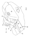
- a circular saw 10 embodying the present invention is shown in schematic form and in the plunged orientation whereby the saw blade (not shown) engages with a work-piece 11.
- the saw 10 comprises a motor housing 12 which includes a handle or gripping portion 14 having a switch 16 for operating the motor.
- a blade guard 18 is arranged to house the saw blade.
- the saw is disposable on to a guide 20 which comprises a support surface 21 and a longitudinal rail 22 protruding from the upper side of the support surface.
- the rail engages with a channel 24 arranged on the lower side of a base plate 26 of the saw 10.
- the saw is able to slide along the guide, being guided by cooperation between the rail and channel on the guide and the base plate, respectively.
- An anti-kickback device 30 is disposed on the saw's base plate 26.
- the device can allow relatively free movement of the saw in the direction of cut, as indicated by arrow A.
- the device can also arrest movement of the saw in a direction opposite to arrow A i.e. opposite to the direction of cut.
- the saw can be prevented from moving in a backwards direction towards the user (opposite to arrow A) by a force exerted onto the saw as the blade engages the work-piece during plunging, for instance.
- a force exerted in this backward direction causes the device to grip the saw to the guide with sufficient friction that the saw is prevented from moving towards the user along the rail.
- the saw can be prevented from jumping off the guide by the device's gripping action onto the guide. In this manner, the saw is held on the guide when/if kickback occurs. Furthermore, the saw is held to the work-piece if the guide is clamped to the work-piece, by connection of the saw to the guide, and the guide to the work-piece.
- an embodiment of the anti-kickback device 30 is shown schematically viewed from above the guide.
- the device comprises a slide member in the form of a cylindrical roller 32 a portion of which, in an "extended” position, extends into the channel 24 of the base plate 26 by a relatively small distance beyond a dashed line B.
- the dashed line B is aligned with an adjacent side wall 34 of the channel 24. When the roller is completely behind the dashed line B it is considered to be in a "retracted” position (not shown).
- the roller is cylindrical and has a central axis 35.
- the roller is urged towards the extended position by a helical spring 36.
- One side of the roller's cylindrical surface 38 engages an opposing side face wall of the rail 22 when the saw is on the guide. The distance by which the roller's surface 38 can extend into the channel is sufficient for the cylindrical surface to contact the rail.
- the position occupied by the rail 22 when the saw is disposed on the guide is shown as dashed lines 22a.
- the dashed lines 22a represent the side walls of the rail disposed in the channel 24.
- the roller 34 can move with respect to the base plate 26 in a direction closer to, or further from, the rail because the roller's cylindrical surface 38 slides along a slide surface 40 which is slightly inclined with respect to the side walls of both the rail and the channel 24.
- the distance between the rail and the cylindrical surface 38 varies depending on the position of the roller.
- the spring 36 urges the roller 34 towards its extended position so that the roller engages the opposing side wall of the rail even when there is no relative movement between the guide and base plate.
- the slightest movement of the base plate relative to the guide in an opposite direction to arrow A causes the roller to slide along the slide surface 40 in the general direction of arrow A with respect to the base plate. This forces the roller to move further towards its extended position thereby wedging the rail between the roller 34 and the channel's opposing side wall 42. This activates the device so that the saw's base plate is locked to the guide.
- the optimum angle of inclination ⁇ between the slide surface 40 and a plane 43 parallel to the adjacent side wall 34 of the channel is between 4 and 10 degrees and preferably 6.5 degrees.
- the angle of inclination ⁇ can be as much as between 2 and 15 degrees.
- the roller 34 has a truncated conical-shaped bevelled edge 46 facing towards the underside of the base plate which bevelled edge allows the saw to be placed directly on top of the rail, rather than sliding the saw onto the guide from one end of the rail.
- the bevelled edge allows the rail to move between the roller and the channel's opposing side wall 42, gently easing the roller out of the rail's path as the rail and channel engage one another. This action can be further assisted if the rail has a rounded edge, in cross-section (not shown).
- the anti-kickback device can be provided with a manually operable button 48.
- the button is coupled to the roller 34 by a pin 50.
- the roller can rotate with respect button.
- the button provides a means for the user to free or unlock the anti-kickback device if ever it becomes wedged stuck during operation.
- the pin is guided by a slot 52 passing through the base plate 26.
- the slot is linear in its longitudinal direction and has a width slightly greater than the diameter of the pin to allow relatively free movement of the pin therein.
- the slot has parallel sides which are parallel to the slide surface 40.
- the user can move the roller out of contact with the rail by pulling the button in a direction Z which is parallel to the slide surface and which moves the roller 32 along or substantially along the slide surface 40 of the retracted position.
- the anti-kickback device is deactivated and the button is in its "operative" position.
- operation of the device is suspended and the circular saw can be moved along the guide in a direction opposite to arrow A (see figures 1 , 2 or 4 , for instance) without the device locking the saw's base plate to the guide.
- This has the benefit of allowing the user to slide the saw back to a starting position on the guide after a cut has been completed without having to lift it from the guide.
- the button is moveable to its operative position against the bias of the spring because the button is coupled to the roller.
- the button has a hook 54 on its edge and the base plate 26 has a finger 56 on its upper side. Engagement between the hook and the finger secures the button in its operative position against the bias of the spring.
- the hook is maintained in engagement with the dowel because the dowel is arranged on the opposite side of the button to the direction of bias of the spring. Disengagement of the hook from the finger causes the button, and hence the roller, to move, under the bias of the spring, away from the button's operative position to where the roller's cylindrical surface is contactable with the rail i.e. the extended position of the roller.
- the hook and finger arrangement is a lock mechanism for holding the roller in the retracted position.
- the sleeve has a hollow generally cylindrical-shape which is adapted to receive a portion of the spring.
- the other end of the spring is secured to a screw 58 in the base plate 26.
- the sleeve is adapted at one end to abut against the cylindrical surface 36 of the roller 34.
- the sleeve, roller, spring and slide surface are housed within the base plate 26 by a cover 59 flush with the underside of the base plate 26.
- the sleeve comprises a pair of ridges 60a, 60b running longitudinally along diametrically opposed external sides of the sleeve.
- One ridge 60a engages an elongate groove 62 in the base plate whilst the other ridge 60b engages an elongate groove 64 in the cover.
- the grooves in the base plate and the cover are longer than the ridges. This allows the sleeve to side back and forth within the device.
- the ridges 60a, 60b and the grooves 62, 64 are parallel to the slide surface 40.
- the coupling member is moveable in a straight line parallel to the inclined surface 40. Containment of the spring within the sleeve ensures that the spring is braced and remains substantially straight and cannot bow laterally outwards, as it is prone to do when most compressed i.e. when the button has been moved to its operative position. If the spring bows laterally outwards it may escape the device which, as a result, will be inoperable. Note that the coupling member is not too long that it inhibits movement of the roller between its extended and retracted positions.
- the roller can be made from any suitable material, such as metal (steel or aluminium for instance), synthetic plastic (high impact nylon for instance), or resilient material (such as rubber). Factors, such as cost of manufacture, wear rates and coefficient of friction, may influence the choice of material.
Abstract
Description
- The present invention relates to an "anti-kickback" device for arresting movement of a rail accommodated within a channel in one direction and for allowing free movement between rail and channel in another opposite direction. This type of device is suitable for use on a manually operated circular saw which has a plunge-cut action and which is guided by the rail and channel arrangement.
- Circular saws with a plunge-cut action are typically known as "plunge saws". Such saws comprise a motor and gearbox disposed in a housing which includes a handle and manually operated switch for activating the motor. The housing is pivotally attached to a base plate which includes a blade guard for accommodating a saw blade which is attached to the gearbox's output spindle. Springs are arranged to urge the housing into a position where the saw blade is wholly accommodated within the blade guard. During use, a user places the base plate on a work-piece, depresses the switch to activate the motor thereby initiating the saw blade's rotation and then plunges the housing towards the work-piece and base plate such that the rotating saw blade passes through an aperture in the base plate and into the work-piece. From this position, the saw can be moved in a forward direction along a cut-line thereby cutting a slot in the work-piece.
DE19635527 describes such a saw. - Kickback can occur as the saw is plunged into the work-piece. The kickback phenomenon is not wholly understood, but it often occurs in the early stages of plunging the blade into the work-piece. As the saw blade first engages with the work-piece kick-back can cause the saw to jump out of the work-piece and back towards the operator with sufficient force to hit the operator. Kick-back might also occur if the saw is twisted out of alignment with the cut during cutting so that the blade catches the edge of the slot cut by the blade. As kick-back occurs, it is thought that the blade "grabs" the work-piece in the slot being cut. In the worse case scenario, the blade can stop rotating with respect to the work-piece and, as the motor continues to drive the blade, the saw is thrown off the work-piece and towards the user at high speed. The user is typically unable to react when kick-back occurs and has insufficient time to disengage power to the motor.
- Thus, kickback is potentially dangerous and could cause severe injury. Furthermore, if a guide is being used to direct the cutting action of the saw as kickback occurs, the saw can jump out of the work-piece and across the guide whilst the blade is exposed from the blade guard and still rotating thereby damaging the guide and/or saw blade.
- Guides are known and can be used to direct various power tools, such as circular saws, plunge saws, routers or jigsaws. The guide can be placed on a work-piece and the tool is then placed on the guide. Clamping devices are often used to secure the guide to the work-piece. Typically, a guide comprises a length of extruded aluminium having a rail which extends along the length of the guide parallel to an edge of the guide along which the power tool operates. In the case of a circular saw, the rail engages with a channel formed in the base plate of the saw. The saw can be placed on the guide such that the rail engages the channel. The operator can run the saw along the guide, directed by the rail, whilst the saw blade cuts the work-piece. A strip of material having a relatively high coefficient of fiction is disposed on the underside of the guide which engages the work-piece to maintain the guide in position during operation of the power tool. This is particularly useful if clamping devices are not available.
-
EP1410818A describes a guide comprising a stop part with an overlapping portion. A plunge saw's base plate has a protruding tang which fits between the guide's rail and an overlapping portion of the stop part. The stop part can be disposed in a channel running along the length of the guide fixed in position with a thumbscrew arrangement. Before plunging the saw into a work-piece, the user places the guide on the work-piece and arranges the stop part in the desired position. The base plate of the saw is then positioned on the guide such that the tang abuts the stop part. Thus, if kickback occurs, the base plate is held on the guide and prevented from jumping backwards towards the operator by the stop part. The stop part and tang combine to form a manually adjusted anti-kickback device. - An anti-kickback device is disclosed by
EP1728604A for arresting movement of a rail accommodated within a channel. The device comprises a slide surface located in one of the rail or channel and inclined in relation to an opposing side wall of the other of the rail or channel. The device comprises a slide member arranged to slide along the slide surface between an extended position and a retracted position further from the side wall than the extended position. The device further comprises a resilient member which biases the slide member along the slide surface towards the extended position and into abutment with the side wall. Movement of the channel in relation to the rail in a longitudinal forward direction causes friction between the slide member and the side wall to push the slide member along the slide surface and towards the retracted position. Movement of the channel in relation to the rail in a longitudinal backward direction opposite to the forward direction causes friction between the slide member and the side wall to push the slide member along the slide surface towards the extended position thereby taking up clearance between the rail and the channel to the extent that the rail is wedged stationary against the channel. As mentioned above, the purpose of such a device is to prevent unexpected and sudden movement of the saw towards the user. Thus, should kick-back occur, the saw is prevented from moving back in a longitudinal backward direction along the rail and towards the operator. Such a device can be integral with a component comprising the rail, like, for example a guide. Alternatively, such a device can be integral with a component comprising the channel, like, for example the base plate of a saw, or the underside of a saw. - The user need only engage the rail and the channel for the anti-kickback device to be ready for action. Thus, no manual adjustment or activation is required and the user will ordinarily assume that the device functions properly. This makes the reliability of the device all the more important because, normally, the user has no need to check it before use.
- The present invention provides an anti-kickback device of the type disclosed in
EP1728604A whereby the resilient member is at least partially received within a hollow elongate sleeve. A resilient member, by its very nature, becomes less stable the more it is compressed. A good example would be a helical spring which is liable to bow laterally outwardly when compressed along its longitudinal axis. The same could apply to a cylindrical rubber bush. The risk of bowing outwardly is reduced, or eliminated, by the hollow elongate sleeve which braces the resilient member in its lateral direction while allowing the resilient member freedom to be compressed, or relaxed, along its longitudinal axis. This helps to prevent the resilient member from detaching itself from the device. The sleeve also helps to house the resilient member where it is safe from interference or damage. - Preferably, the sleeve is a hollow cylinder and the resilient member is a helical spring. A helical spring is a freely available item which can be manufactured small enough to be housed in a compact space. The hollow cylinder braces the helical spring when it is compressed inside the sleeve which helps prevent the spring from bowing laterally outwardly.
- Preferably, the sleeve is guided along a straight path by a guidance mechanism. The guidance mechanism is part of the device and prevents the sleeve from moving laterally outwardly from the device. This further enhances the ability of the sleeve to prevent the spring from bowing laterally outwardly. That is because the sleeve can only travel along the straight path and so the helical spring, which is braced by the sleeve, cannot stray from the straight path and leave the device.
- The guidance mechanism may be any system capable of guiding the sleeve along a straight path. Preferably, the guidance mechanism comprises a ridge on the sleeve which is slideable within with an elongate groove in the one of the rail or channel. Alternatively, the guidance mechanism comprises a ridge in the one of the rail or channel which is slideable within with an elongate groove on the sleeve. Either of these two variants is a simple and inexpensive guidance mechanism.
- Preferably, there is a ridge on opposite sides of the sleeve, wherein each ridge has a corresponding groove. Having ridges on opposing sides of the sleeve improves stability as the sleeve moves along the straight path because it is guided on two diametrically opposing sides and is less likely to become stuck.
- Preferably, the slide member is a cylindrical roller with a central axis arranged parallel to the slide surface. The lines of contact between the cylindrical roller and the slide surface, on the one hand, and between the cylindrical roller and the rail or the channel, on the other hand, make the roller less prone to jamming than a face-to-face contact, as would be the case of the slide member were, for example, cube-shaped.
- Preferably, the device further comprises a manually operable button coupled to the slide member to enable user-operated movement of the slide member towards the retracted position. This may be necessary in the rare event that the slide member is wedged stuck between the slide surface and the side wall causing the rail to be immobilised in relation to the channel. This may also be necessary in the more common event where the user wishes to suspend operation of the device and allow free movement of the channel in relation to the rail in a longitudinal backward direction. For example, when the user wishes to slide the plunge saw in the longitudinal direction back to its start position and without lifting it from the guide. With the slide member forced into the retracted position there can be no friction between the slide member and the side wall.
- Preferably, the device further comprises a lock mechanism for holding the slide member in the retracted position. This is the case when a user wishes to temporarily suspend operation of the device and allow free movement of the channel in relation to the rail in both longitudinal directions. The lock does this whilst freeing both the user's hands to slide the plunge saw back to its start position and without the need to lift it from the guide.
- Preferably, the lock mechanism comprises a hook on the button for engagement with a dowel on the one of the rail or channel. This is a simple and inexpensive lock mechanism. It can rely on the bias of the resilient member to maintain the hook engaged with the dowel if the dowel is arranged on the opposite side of the button to the direction of bias of the resilient member.
- Preferably, the button is coupled to the slide member by a pin passing through a linear slot in the one of the rail or channel, wherein the slot is parallel to the slide surface. Thus, the slot and pin arrangement do not interfere with the slide member's contact with the slide surface.
- The present invention also provides a hand-operated tool guidable by a rail, the tool comprising a main housing, a base plate coupled to the main housing, and an elongate channel in one side of the base plate, wherein the channel is arranged to accommodate a rail and the base plate comprises the anti-kickback device.
- The present invention further provides a guide for guiding a hand-operated tool, the guide comprising: a support surface, and a rail protruding from one side of the support surface, wherein rail is arranged to be accommodated within an elongate channel in one side of a tool and the guide comprises the anti-kickback device.
- An embodiment of the present invention is now described by way of example, with reference to the following drawings, in which:
-
Figure 1 shows a schematic diagram of a circular saw embodying the present invention and being disposed on a guide; -
Figure 2 shows schematically an anti-kickback device for the circular saw; -
Figure 3 shows schematically the device, and shown in cross-section along line III-III offigure 2 ; -
Figure 4 shows schematically the device, and shown in cross-section along line IV-IV offigure 3 ; -
Figure 5 is a perspective view of the upper side of a base plate of the circular saw; -
Figure 6 is the same view asfigure 5 without a knob connected to the device; -
Figure 7 is a perspective view of the lower side of the base plate; and -
Figure 8 is the same view asfigure 7 without a cover for the device. - Referring to
figure 1 , acircular saw 10 embodying the present invention is shown in schematic form and in the plunged orientation whereby the saw blade (not shown) engages with a work-piece 11. Thesaw 10 comprises amotor housing 12 which includes a handle or grippingportion 14 having aswitch 16 for operating the motor. Ablade guard 18 is arranged to house the saw blade. The saw is disposable on to aguide 20 which comprises asupport surface 21 and alongitudinal rail 22 protruding from the upper side of the support surface. The rail engages with achannel 24 arranged on the lower side of abase plate 26 of thesaw 10. Thus, the saw is able to slide along the guide, being guided by cooperation between the rail and channel on the guide and the base plate, respectively. - An
anti-kickback device 30 is disposed on the saw'sbase plate 26. The device can allow relatively free movement of the saw in the direction of cut, as indicated by arrow A. The device can also arrest movement of the saw in a direction opposite to arrow A i.e. opposite to the direction of cut. Thus, as the saw is plunged into the work-piece, the saw can be prevented from moving in a backwards direction towards the user (opposite to arrow A) by a force exerted onto the saw as the blade engages the work-piece during plunging, for instance. Such a force exerted in this backward direction causes the device to grip the saw to the guide with sufficient friction that the saw is prevented from moving towards the user along the rail. Further, the saw can be prevented from jumping off the guide by the device's gripping action onto the guide. In this manner, the saw is held on the guide when/if kickback occurs. Furthermore, the saw is held to the work-piece if the guide is clamped to the work-piece, by connection of the saw to the guide, and the guide to the work-piece. - Referring to
figure 2 , an embodiment of theanti-kickback device 30 is shown schematically viewed from above the guide. The device comprises a slide member in the form of a cylindrical roller 32 a portion of which, in an "extended" position, extends into thechannel 24 of thebase plate 26 by a relatively small distance beyond a dashed line B. The dashed line B is aligned with anadjacent side wall 34 of thechannel 24. When the roller is completely behind the dashed line B it is considered to be in a "retracted" position (not shown). - The roller is cylindrical and has a
central axis 35. The roller is urged towards the extended position by ahelical spring 36. One side of the roller'scylindrical surface 38 engages an opposing side face wall of therail 22 when the saw is on the guide. The distance by which the roller'ssurface 38 can extend into the channel is sufficient for the cylindrical surface to contact the rail. - The position occupied by the
rail 22 when the saw is disposed on the guide is shown as dashedlines 22a. The dashedlines 22a represent the side walls of the rail disposed in thechannel 24. Theroller 34 can move with respect to thebase plate 26 in a direction closer to, or further from, the rail because the roller'scylindrical surface 38 slides along aslide surface 40 which is slightly inclined with respect to the side walls of both the rail and thechannel 24. Thus, the distance between the rail and thecylindrical surface 38 varies depending on the position of the roller. - The
spring 36 urges theroller 34 towards its extended position so that the roller engages the opposing side wall of the rail even when there is no relative movement between the guide and base plate. The slightest movement of the base plate relative to the guide in an opposite direction to arrow A causes the roller to slide along theslide surface 40 in the general direction of arrow A with respect to the base plate. This forces the roller to move further towards its extended position thereby wedging the rail between theroller 34 and the channel's opposingside wall 42. This activates the device so that the saw's base plate is locked to the guide. - Conversely, movement of the base plate relative to the guide in the direction of arrow A is permitted because the roller produces minimal sliding friction between itself and the opposing side wall of the rail. The result is equilibrium between the bias of the spring in one direction and the frictional force in the opposite direction which maintains the roller between its extended and retracted positions. The device is not activated and the saw's base plate is not locked to the guide. The spring constant of
spring 36 should be chosen so that the force exerted on the roller by the spring is relatively low. - The optimum angle of inclination α between the
slide surface 40 and aplane 43 parallel to theadjacent side wall 34 of the channel is between 4 and 10 degrees and preferably 6.5 degrees. However, the angle of inclination α can be as much as between 2 and 15 degrees. - Referring to
figure 3 , theroller 34 has a truncated conical-shapedbevelled edge 46 facing towards the underside of the base plate which bevelled edge allows the saw to be placed directly on top of the rail, rather than sliding the saw onto the guide from one end of the rail. In other words, as the saw is placed on the support surface, the bevelled edge allows the rail to move between the roller and the channel's opposingside wall 42, gently easing the roller out of the rail's path as the rail and channel engage one another. This action can be further assisted if the rail has a rounded edge, in cross-section (not shown). - In addition, the anti-kickback device can be provided with a manually
operable button 48. The button is coupled to theroller 34 by apin 50. The roller can rotate with respect button. The button provides a means for the user to free or unlock the anti-kickback device if ever it becomes wedged stuck during operation. The pin is guided by aslot 52 passing through thebase plate 26. The slot is linear in its longitudinal direction and has a width slightly greater than the diameter of the pin to allow relatively free movement of the pin therein. The slot has parallel sides which are parallel to theslide surface 40. - Referring to
figure 4 , the user can move the roller out of contact with the rail by pulling the button in a direction Z which is parallel to the slide surface and which moves theroller 32 along or substantially along theslide surface 40 of the retracted position. When the roller is held away from therail 22 in its retracted position the anti-kickback device is deactivated and the button is in its "operative" position. As such, operation of the device is suspended and the circular saw can be moved along the guide in a direction opposite to arrow A (seefigures 1 ,2 or4 , for instance) without the device locking the saw's base plate to the guide. This has the benefit of allowing the user to slide the saw back to a starting position on the guide after a cut has been completed without having to lift it from the guide. - The button is moveable to its operative position against the bias of the spring because the button is coupled to the roller. Referring to
figures 5 and6 , the button has ahook 54 on its edge and thebase plate 26 has afinger 56 on its upper side. Engagement between the hook and the finger secures the button in its operative position against the bias of the spring. The hook is maintained in engagement with the dowel because the dowel is arranged on the opposite side of the button to the direction of bias of the spring. Disengagement of the hook from the finger causes the button, and hence the roller, to move, under the bias of the spring, away from the button's operative position to where the roller's cylindrical surface is contactable with the rail i.e. the extended position of the roller. The hook and finger arrangement is a lock mechanism for holding the roller in the retracted position. - Referring now to
figures 8 and 9, anelongate sleeve 54 for coupling thespring 36 to theroller 32 is shown. The sleeve has a hollow generally cylindrical-shape which is adapted to receive a portion of the spring. The other end of the spring is secured to ascrew 58 in thebase plate 26. The sleeve is adapted at one end to abut against thecylindrical surface 36 of theroller 34. The sleeve, roller, spring and slide surface are housed within thebase plate 26 by acover 59 flush with the underside of thebase plate 26. The sleeve comprises a pair of ridges 60a, 60b running longitudinally along diametrically opposed external sides of the sleeve. One ridge 60a engages anelongate groove 62 in the base plate whilst the other ridge 60b engages anelongate groove 64 in the cover. The grooves in the base plate and the cover are longer than the ridges. This allows the sleeve to side back and forth within the device. The ridges 60a, 60b and thegrooves slide surface 40. Thus, the coupling member is moveable in a straight line parallel to theinclined surface 40. Containment of the spring within the sleeve ensures that the spring is braced and remains substantially straight and cannot bow laterally outwards, as it is prone to do when most compressed i.e. when the button has been moved to its operative position. If the spring bows laterally outwards it may escape the device which, as a result, will be inoperable. Note that the coupling member is not too long that it inhibits movement of the roller between its extended and retracted positions. - The roller can be made from any suitable material, such as metal (steel or aluminium for instance), synthetic plastic (high impact nylon for instance), or resilient material (such as rubber). Factors, such as cost of manufacture, wear rates and coefficient of friction, may influence the choice of material.
Claims (13)
- A device (30) for arresting movement of a rail (22) accommodated within a channel (24), wherein the device comprises:a slide surface (40) located in one of the rail or channel and inclined in relation to an opposing side wall (42) of the other of the rail or channel;a slide member (34) arranged to slide along the slide surface between a extended position and a retracted position further from the side wall than the extended position; anda resilient member (36) which biases the slide member along the slide surface towards the extended position and into abutment with the side wall, wherein movement of the channel in relation to the rail in a longitudinal forward direction causes friction between the slide member and the side wall to push the slide member along the slide surface and towards the retracted position, wherein movement of the channel in relation to the rail in a longitudinal backward direction opposite to the forward direction causes friction between the slide member and the side wall to push the slide member along the slide surface towards the extended position thereby taking up clearance between the rail and the channel to the extent that the rail is wedged stationary against the channel, characterised in that the resilient member is at least partially received within a hollow elongate sleeve (54).
- A device as claimed in claim 1, wherein the sleeve is a hollow cylinder (54) and the resilient member is a helical spring (36).
- A device as claimed in either one of claims 1 or 2, wherein the sleeve (54) is guided along a straight path by a guidance mechanism (60a, 60b, 62, 64).
- A device as claimed in claim 3, wherein the guidance mechanism comprises a ridge (60a, 60b) on the sleeve which is slideable within with an elongate groove (62, 64) in the one of the rail or channel.
- A device as claimed in claim 3, wherein the guidance mechanism comprises a ridge (60a, 60b) in the one of the rail or channel which is slideable within with an elongate groove (62, 64) on the sleeve.
- A device as claimed in either one of claims 4 or 5, wherein there is a ridge (60a, 60b) on opposite sides of the sleeve, wherein each ridge has a corresponding groove (62, 64).
- A device as claimed in any one of the previous claims, wherein the slide member is a cylindrical roller (34) with a central axis (35) arranged parallel to the slide surface (40).
- A device as claimed in any one of the previous claims, further comprising a manually operable button (46) coupled to the slide member (34) to enable user-perated movement of the slide member towards the retracted position.
- A device as claimed in claims 8, further comprising a lock mechanism (48, 50, 54, 56) for holding the slide member in the retracted position.
- A device as claimed in claim 9, wherein the lock mechanism comprises a hook (54) on the button (48) for engagement with a dowel (56) on the one of the rail or channel.
- A device as claimed in any one of claims 8 to 10, wherein the button is coupled to the slide member by a pin (50) passing through a linear slot (52) in the one of the rail or channel, wherein the slot is parallel to the slide surface.
- A hand-operated tool (10) guidable by a rail (22), the tool comprising;a main housing (12, 14);a base plate (26) coupled to the main housing; anda channel (24) in one side of the base plate,wherein the channel is arranged to accommodate a rail (22) and the base plate comprises the device (30) as claimed in any one of claims 1 to 11.
- A guide (20) for guiding a hand-operated tool (10), the guide comprising:a support surface (21); anda rail (12) protruding from one side of the support surface,wherein rail is arranged to be accommodated within a channel (24) in one side of a tool (10) and the guide comprises the device (30) as claimed in any one of claims 1 to 11.
Priority Applications (4)
| Application Number | Priority Date | Filing Date | Title |
|---|---|---|---|
| EP20070113274 EP2018920B1 (en) | 2007-07-26 | 2007-07-26 | Anti-kickback device |
| AU2008202876A AU2008202876B2 (en) | 2007-07-26 | 2008-06-30 | Anti-kickback device |
| US12/167,443 US7905166B2 (en) | 2007-07-26 | 2008-07-03 | Anti-kickback device |
| CNA2008101442282A CN101352769A (en) | 2007-07-26 | 2008-07-25 | Anti-kickback device |
Applications Claiming Priority (1)
| Application Number | Priority Date | Filing Date | Title |
|---|---|---|---|
| EP20070113274 EP2018920B1 (en) | 2007-07-26 | 2007-07-26 | Anti-kickback device |
Publications (2)
| Publication Number | Publication Date |
|---|---|
| EP2018920A1 true EP2018920A1 (en) | 2009-01-28 |
| EP2018920B1 EP2018920B1 (en) | 2011-09-07 |
Family
ID=38698294
Family Applications (1)
| Application Number | Title | Priority Date | Filing Date |
|---|---|---|---|
| EP20070113274 Expired - Fee Related EP2018920B1 (en) | 2007-07-26 | 2007-07-26 | Anti-kickback device |
Country Status (4)
| Country | Link |
|---|---|
| US (1) | US7905166B2 (en) |
| EP (1) | EP2018920B1 (en) |
| CN (1) | CN101352769A (en) |
| AU (1) | AU2008202876B2 (en) |
Cited By (2)
| Publication number | Priority date | Publication date | Assignee | Title |
|---|---|---|---|---|
| EP2762282B1 (en) | 2013-01-30 | 2018-03-21 | Makita Corporation | Cutting devices |
| DE102022108226A1 (en) | 2021-04-12 | 2022-10-13 | Makita Corporation | ANTI-KICKBACK STOPPER, ACCESSORIES KIT FOR USE WITH PORTABLE CUTTING MACHINE AND PORTABLE CUTTING SYSTEM |
Families Citing this family (10)
| Publication number | Priority date | Publication date | Assignee | Title |
|---|---|---|---|---|
| EP1862275B1 (en) * | 2006-06-02 | 2016-09-28 | Black & Decker, Inc. | A plunge-cut circular saw |
| US8037610B2 (en) * | 2008-12-30 | 2011-10-18 | Crain Cutter Co., Inc. | Powered groover with airflow fin |
| WO2015007032A1 (en) * | 2013-07-15 | 2015-01-22 | 江苏苏美达五金工具有限公司 | Portable hand-held circular saw |
| CN103419068B (en) * | 2013-07-15 | 2015-06-24 | 江苏苏美达五金工具有限公司 | Portable handheld circular saw |
| WO2015010007A1 (en) * | 2013-07-18 | 2015-01-22 | Affinity Tool Works, Llc | Multifunction cutting tool guide |
| JP6599138B2 (en) * | 2015-06-18 | 2019-10-30 | 株式会社マキタ | Dust collecting cover of cutting machine |
| KR101769827B1 (en) * | 2015-10-08 | 2017-09-05 | 두산중공업 주식회사 | Pipe cutting apparatus comprising re-fitting object for cutting a steam pipe of the waste nuclear generators |
| US10875109B1 (en) | 2018-04-30 | 2020-12-29 | Kreg Enterprises, Inc. | Adaptive cutting system |
| KR102530200B1 (en) * | 2018-12-20 | 2023-05-09 | 현대트랜시스 주식회사 | Seat track mechanism for vehicle seat |
| USD918685S1 (en) * | 2019-01-28 | 2021-05-11 | Kreg Enterprises, Inc. | Plunge cut saw and guide system |
Citations (5)
| Publication number | Priority date | Publication date | Assignee | Title |
|---|---|---|---|---|
| DE1600235A1 (en) * | 1966-10-15 | 1970-02-05 | Zahnradfabrik Friedrichshafen | Pinch roller overrunning clutch |
| DE29812871U1 (en) * | 1998-07-20 | 1998-10-15 | Ho Chih Kwo | Circular saw with a divided base |
| EP1410818A1 (en) | 2002-10-14 | 2004-04-21 | Sergio Restelli | Vial for injection and relative safety device |
| EP1418018A1 (en) * | 2002-11-06 | 2004-05-12 | Festool GmbH | Guide rail for hand held machine-tools and associated stop |
| EP1728604A1 (en) * | 2005-06-01 | 2006-12-06 | BLACK & DECKER INC. | Circular saw with anti-kickback device |
Family Cites Families (11)
| Publication number | Priority date | Publication date | Assignee | Title |
|---|---|---|---|---|
| US2438023A (en) * | 1943-09-15 | 1948-03-16 | Western Electric Co | Apparatus for cutting wires and forming and attaching a sleeve thereto |
| US3298407A (en) * | 1964-07-30 | 1967-01-17 | Hugh A Scott | Clean cut saws |
| US3600047A (en) * | 1970-03-11 | 1971-08-17 | Unity Railway Supply Co Inc | Precompressed side bearing |
| DE3341003C2 (en) * | 1983-11-12 | 1986-01-30 | Festo-Maschinenfabrik Gottlieb Stoll, 7300 Esslingen | Guide device for a transportable saw |
| IT8421899V0 (en) * | 1984-05-23 | 1984-05-23 | Black & Decker Inc | HAND TRANSLABLE DISC SAW WITH UNIDIRECTIONAL BRAKING DEVICE. |
| DE4001331A1 (en) * | 1990-01-18 | 1991-07-25 | Reich Maschf Gmbh Karl | Cutting coated wooden etc. workpieces by circular saw - cuts cover layer in two orthogonal directions, and then entire cross=section in opposite cuts |
| DE4322303A1 (en) * | 1993-07-05 | 1995-01-12 | Bosch Gmbh Robert | Hand tool |
| DE19635527A1 (en) | 1996-08-20 | 1998-02-26 | Black & Decker Inc | Hand-held circular saw |
| US6769674B2 (en) * | 2002-05-15 | 2004-08-03 | Huei-Yu Chang | Foldable workbench |
| US6917755B2 (en) * | 2003-02-27 | 2005-07-12 | Applied Materials, Inc. | Substrate support |
| DE102004002275B4 (en) * | 2004-01-16 | 2011-05-19 | Hilti Aktiengesellschaft | Hand tool |
-
2007
- 2007-07-26 EP EP20070113274 patent/EP2018920B1/en not_active Expired - Fee Related
-
2008
- 2008-06-30 AU AU2008202876A patent/AU2008202876B2/en not_active Ceased
- 2008-07-03 US US12/167,443 patent/US7905166B2/en not_active Expired - Fee Related
- 2008-07-25 CN CNA2008101442282A patent/CN101352769A/en active Pending
Patent Citations (5)
| Publication number | Priority date | Publication date | Assignee | Title |
|---|---|---|---|---|
| DE1600235A1 (en) * | 1966-10-15 | 1970-02-05 | Zahnradfabrik Friedrichshafen | Pinch roller overrunning clutch |
| DE29812871U1 (en) * | 1998-07-20 | 1998-10-15 | Ho Chih Kwo | Circular saw with a divided base |
| EP1410818A1 (en) | 2002-10-14 | 2004-04-21 | Sergio Restelli | Vial for injection and relative safety device |
| EP1418018A1 (en) * | 2002-11-06 | 2004-05-12 | Festool GmbH | Guide rail for hand held machine-tools and associated stop |
| EP1728604A1 (en) * | 2005-06-01 | 2006-12-06 | BLACK & DECKER INC. | Circular saw with anti-kickback device |
Cited By (2)
| Publication number | Priority date | Publication date | Assignee | Title |
|---|---|---|---|---|
| EP2762282B1 (en) | 2013-01-30 | 2018-03-21 | Makita Corporation | Cutting devices |
| DE102022108226A1 (en) | 2021-04-12 | 2022-10-13 | Makita Corporation | ANTI-KICKBACK STOPPER, ACCESSORIES KIT FOR USE WITH PORTABLE CUTTING MACHINE AND PORTABLE CUTTING SYSTEM |
Also Published As
| Publication number | Publication date |
|---|---|
| US20090049970A1 (en) | 2009-02-26 |
| AU2008202876B2 (en) | 2014-01-16 |
| US7905166B2 (en) | 2011-03-15 |
| CN101352769A (en) | 2009-01-28 |
| AU2008202876A1 (en) | 2009-02-12 |
| EP2018920B1 (en) | 2011-09-07 |
Similar Documents
| Publication | Publication Date | Title |
|---|---|---|
| EP2018920B1 (en) | Anti-kickback device | |
| US7908952B2 (en) | Anti-kickback device | |
| US6735876B2 (en) | Blade clamps suitable for reciprocating power tools | |
| US5052255A (en) | Speed brake | |
| US7814818B2 (en) | Modular table saw guarding system riving knife release mechanisms | |
| EP2086731B1 (en) | A modular guard systems for a power saw | |
| US7540224B2 (en) | Straddle safety pusher system | |
| US7137326B2 (en) | Translation stop for use in power equipment | |
| EP1842635B1 (en) | Circular saw with anti-kickback device | |
| US4637288A (en) | Safety mechanism for saws | |
| US4065114A (en) | Guide for a motorized circular handsaw | |
| EP0213172B1 (en) | A displaceable protective cover for handtools provided with rotatable disc-shaped tools | |
| CA2473676C (en) | Straddle safety pusher system | |
| US2985202A (en) | Circular saw safety device | |
| EP3792023A2 (en) | Saw | |
| US4430795A (en) | Safety device for chain saw | |
| EP1514626B1 (en) | Shoe assembly for power tool and power tool incorporating such assembly | |
| EP0035380A1 (en) | Saw assembly and work table therefor | |
| US3485326A (en) | Magnetic stopping device |
Legal Events
| Date | Code | Title | Description |
|---|---|---|---|
| PUAI | Public reference made under article 153(3) epc to a published international application that has entered the european phase |
Free format text: ORIGINAL CODE: 0009012 |
|
| AK | Designated contracting states |
Kind code of ref document: A1 Designated state(s): AT BE BG CH CY CZ DE DK EE ES FI FR GB GR HU IE IS IT LI LT LU LV MC MT NL PL PT RO SE SI SK TR |
|
| AX | Request for extension of the european patent |
Extension state: AL BA HR MK RS |
|
| 17P | Request for examination filed |
Effective date: 20090204 |
|
| 17Q | First examination report despatched |
Effective date: 20090408 |
|
| AKX | Designation fees paid |
Designated state(s): DE GB SE |
|
| GRAP | Despatch of communication of intention to grant a patent |
Free format text: ORIGINAL CODE: EPIDOSNIGR1 |
|
| GRAS | Grant fee paid |
Free format text: ORIGINAL CODE: EPIDOSNIGR3 |
|
| RIN1 | Information on inventor provided before grant (corrected) |
Inventor name: KEENLYSIDE, SCOTT Inventor name: THOMAS, ROGER |
|
| GRAA | (expected) grant |
Free format text: ORIGINAL CODE: 0009210 |
|
| REG | Reference to a national code |
Ref country code: GB Ref legal event code: FG4D |
|
| REG | Reference to a national code |
Ref country code: SE Ref legal event code: TRGR |
|
| REG | Reference to a national code |
Ref country code: DE Ref legal event code: R096 Ref document number: 602007016922 Country of ref document: DE Effective date: 20111201 |
|
| PLBE | No opposition filed within time limit |
Free format text: ORIGINAL CODE: 0009261 |
|
| STAA | Information on the status of an ep patent application or granted ep patent |
Free format text: STATUS: NO OPPOSITION FILED WITHIN TIME LIMIT |
|
| 26N | No opposition filed |
Effective date: 20120611 |
|
| REG | Reference to a national code |
Ref country code: DE Ref legal event code: R097 Ref document number: 602007016922 Country of ref document: DE Effective date: 20120611 |
|
| PGFP | Annual fee paid to national office [announced via postgrant information from national office to epo] |
Ref country code: SE Payment date: 20180710 Year of fee payment: 12 |
|
| REG | Reference to a national code |
Ref country code: SE Ref legal event code: EUG |
|
| PG25 | Lapsed in a contracting state [announced via postgrant information from national office to epo] |
Ref country code: SE Free format text: LAPSE BECAUSE OF NON-PAYMENT OF DUE FEES Effective date: 20190727 |
|
| PGFP | Annual fee paid to national office [announced via postgrant information from national office to epo] |
Ref country code: GB Payment date: 20200716 Year of fee payment: 14 Ref country code: DE Payment date: 20200714 Year of fee payment: 14 |
|
| REG | Reference to a national code |
Ref country code: DE Ref legal event code: R119 Ref document number: 602007016922 Country of ref document: DE |
|
| GBPC | Gb: european patent ceased through non-payment of renewal fee |
Effective date: 20210726 |
|
| PG25 | Lapsed in a contracting state [announced via postgrant information from national office to epo] |
Ref country code: GB Free format text: LAPSE BECAUSE OF NON-PAYMENT OF DUE FEES Effective date: 20210726 Ref country code: DE Free format text: LAPSE BECAUSE OF NON-PAYMENT OF DUE FEES Effective date: 20220201 |