EP2022946A1 - Jet engine containing a current generator mounted in the fan and an assembly method for said generator in the fan - Google Patents
Jet engine containing a current generator mounted in the fan and an assembly method for said generator in the fan Download PDFInfo
- Publication number
- EP2022946A1 EP2022946A1 EP08161954A EP08161954A EP2022946A1 EP 2022946 A1 EP2022946 A1 EP 2022946A1 EP 08161954 A EP08161954 A EP 08161954A EP 08161954 A EP08161954 A EP 08161954A EP 2022946 A1 EP2022946 A1 EP 2022946A1
- Authority
- EP
- European Patent Office
- Prior art keywords
- fan
- current generator
- rotor
- turbojet engine
- generator
- Prior art date
- Legal status (The legal status is an assumption and is not a legal conclusion. Google has not performed a legal analysis and makes no representation as to the accuracy of the status listed.)
- Granted
Links
- 238000000034 method Methods 0.000 title claims abstract description 6
- 238000011144 upstream manufacturing Methods 0.000 claims abstract description 22
- 230000005540 biological transmission Effects 0.000 claims description 7
- 230000001050 lubricating effect Effects 0.000 claims 1
- 238000005461 lubrication Methods 0.000 description 6
- 239000007789 gas Substances 0.000 description 5
- 238000004804 winding Methods 0.000 description 5
- 238000001816 cooling Methods 0.000 description 4
- 230000006835 compression Effects 0.000 description 2
- 238000007906 compression Methods 0.000 description 2
- 239000000314 lubricant Substances 0.000 description 2
- 230000004048 modification Effects 0.000 description 2
- 238000012986 modification Methods 0.000 description 2
- 238000002485 combustion reaction Methods 0.000 description 1
- 230000003750 conditioning effect Effects 0.000 description 1
- 230000009977 dual effect Effects 0.000 description 1
- 230000000694 effects Effects 0.000 description 1
- 238000012423 maintenance Methods 0.000 description 1
- 239000002184 metal Substances 0.000 description 1
- 210000000056 organ Anatomy 0.000 description 1
- 238000010257 thawing Methods 0.000 description 1
Images

Classifications
-
- F—MECHANICAL ENGINEERING; LIGHTING; HEATING; WEAPONS; BLASTING
- F01—MACHINES OR ENGINES IN GENERAL; ENGINE PLANTS IN GENERAL; STEAM ENGINES
- F01D—NON-POSITIVE DISPLACEMENT MACHINES OR ENGINES, e.g. STEAM TURBINES
- F01D15/00—Adaptations of machines or engines for special use; Combinations of engines with devices driven thereby
- F01D15/10—Adaptations for driving, or combinations with, electric generators
-
- F—MECHANICAL ENGINEERING; LIGHTING; HEATING; WEAPONS; BLASTING
- F02—COMBUSTION ENGINES; HOT-GAS OR COMBUSTION-PRODUCT ENGINE PLANTS
- F02K—JET-PROPULSION PLANTS
- F02K3/00—Plants including a gas turbine driving a compressor or a ducted fan
- F02K3/02—Plants including a gas turbine driving a compressor or a ducted fan in which part of the working fluid by-passes the turbine and combustion chamber
- F02K3/04—Plants including a gas turbine driving a compressor or a ducted fan in which part of the working fluid by-passes the turbine and combustion chamber the plant including ducted fans, i.e. fans with high volume, low pressure outputs, for augmenting the jet thrust, e.g. of double-flow type
- F02K3/06—Plants including a gas turbine driving a compressor or a ducted fan in which part of the working fluid by-passes the turbine and combustion chamber the plant including ducted fans, i.e. fans with high volume, low pressure outputs, for augmenting the jet thrust, e.g. of double-flow type with front fan
-
- Y—GENERAL TAGGING OF NEW TECHNOLOGICAL DEVELOPMENTS; GENERAL TAGGING OF CROSS-SECTIONAL TECHNOLOGIES SPANNING OVER SEVERAL SECTIONS OF THE IPC; TECHNICAL SUBJECTS COVERED BY FORMER USPC CROSS-REFERENCE ART COLLECTIONS [XRACs] AND DIGESTS
- Y02—TECHNOLOGIES OR APPLICATIONS FOR MITIGATION OR ADAPTATION AGAINST CLIMATE CHANGE
- Y02T—CLIMATE CHANGE MITIGATION TECHNOLOGIES RELATED TO TRANSPORTATION
- Y02T50/00—Aeronautics or air transport
- Y02T50/60—Efficient propulsion technologies, e.g. for aircraft
Definitions
- the invention relates to a gas turbine engine with an upstream fan and a method for mounting an electric current generator in the turbojet engine.
- Part of the power generated by an aeronautical turbojet engine is used to feed different organs, both of the turbojet engine but also of the aircraft whose turbojet engine is involved in propulsion.
- HP high pressure compressor
- compressed air is used, in particular to ensure the pressurization and conditioning of the cabin of the aircraft, or defrosting.
- Another part of this power is taken mechanically on the shaft of the stage HP of the turbojet, to drive the input shaft of an accessory box placed on a turbojet engine casing.
- This input shaft is rotated by a transmission shaft extending in a structural arm of the housing and itself driven by a pinion integral with the HP shaft.
- the current trend is to increase the installed electrical power, and thus the mechanical power draws on the engine.
- He is also known by the patent application W02007 / 036202 to mount an electric current generator in the turbojet engine body.
- the generator is composed of a stator element, disposed circumferentially in the compression casing of the turbojet, and rotor elements fixed to the blade ends integral with the HP shaft and rotated in the compression housing of the turbojet engine.
- the rotational movement of the rotor elements induces a current in the stator element which is transmitted to the different equipment to be powered.
- a current generator is difficult to access and involves partially dismantling the turbojet engine during its replacement or maintenance.
- the compressor housing is of reduced size which complicates the routing of the generated current to the different equipment.
- the Applicant has proposed a double-body gas turbine engine comprising a high-pressure rotor and a low-pressure rotor, the low-pressure rotor shaft being connected, at its upstream end, to a fan housed in a fan casing, characterized in that it comprises, upstream of the fan, a fixed bonnet element centered on the axis of the motor, on which is mounted an electric current generator arranged to collect the mechanical power of the low pressure rotor shaft and convert it into electrical power.
- the turbojet advantageously makes it possible not to draw power on the HP rotor shaft.
- the current generator is easy to access which allows its replacement in a limited time by dismantling a minimum of turbojet parts.
- the current generator is placed upstream of the fan, in a cold zone of the turbojet, which reduces its cooling requirements and therefore its mass.
- the current generator comprises a stator element connected to the fixed hood element, a rotor element being driven by the upstream end of the low pressure rotor shaft.
- the turbojet comprises a fan disk on which are mounted the fan blades.
- a rotor element of the current generator is rotated by a journal integral with said fan disk.
- the bonnet element is advantageously connected to the fan casing by radial retaining arms.
- the radial arms make it possible to fix the stator element of the generator without creating significant structural modifications of the turbojet engine.
- Lubrication lines of the current generator and electrical cables are formed in the radial support arms.
- power transmission gears are respectively formed on the rotor element of the current generator and on the upstream end of the low pressure rotor shaft, the gears meshing with each other. for transmitting the rotational movement of the low pressure rotor shaft to the rotor element of the current generator.
- the assembly of the generator is simple and is performed upstream of the turbojet engine.
- the manipulated parts are of reduced size and low mass which allows a quick replacement of the current generator.
- the turbojet engine of the invention is a double-body gas turbine engine 100, comprising a low pressure rotor (LP) and a high pressure rotor (HP) 1, rotatably mounted about the axis X3 of the turbojet engine.
- LP low pressure rotor
- HP high pressure rotor
- the turbojet engine comprises functionally, from upstream to downstream in the direction of flow of gases, a fan 10, a compressor, a combustion chamber, a turbine and an exhaust nozzle.
- a fan 10 As it is dual body, it includes a BP compressor, upstream of an HP compressor, and an HP turbine, upstream of a LP turbine.
- the blower 10, figure 1 comprises a fan disk 19 fixed by a flange to a pin 15, itself supported by a bearing integral with the intermediate casing, the pin 15 being here secured to the low pressure shaft 2.
- the fan 10 further comprises a movable cowl element 11 which is fixed on the fan disk 19.
- the movable cowl element 11 is of frustoconical shape and serves to guide the air intake stream.
- a fixed hood element 12 is disposed upstream of the movable hood element 11.
- the fan 10 is rotated in the fan casing 14 by the rotor shaft BP 2 rotatably connected to the movable cowl element 11.
- a housing 13 is formed in the movable cowl element 11.
- an electric current generator 20 is mounted on the fixed hood element 12, the generator 20 comprising a stator element 21, integrally connected to the fixed hood element 12, and a rotor element 22 free to rotate with respect to the fixed hood element 12.
- the rotor element 22 is here an electromagnet extending axially along the axis X3.
- the stator element 21 is composed of windings which extend coaxially and externally to the rotor element 22.
- a bearing 23 rotatably supports the rotor element 21 in the stator element 21.
- Radial holding arms 16 structurally connect the fixed hood element 12 to the fan casing 14, the stator element 21 of the current generator 20 thus remaining stationary during the rotation of the fan blades 18.
- the holding arms 16 are secured by a flange on the fan casing 14.
- the holding arms 16 are advantageously hollow and can accommodate the lubrication ducts 41 of the current generator 20 and the electric cables 42 shown in FIG. figure 2 .
- the upper holding arm 16 is shown in transparency over part of its length in order to allow the observation of the lubrication ducts 41 of the current generator 20 and the electric cables 42.
- the lubricant ducts 41 of the current generator 20 make it possible to convey a lubricant, such as oil, from an oil tank, placed downstream of the fan, to the current generator 20 to allow cooling and the lubrication of the current generator 20.
- a lubricant such as oil
- the electric cables 42 make it possible to conduct the current generated in the windings 21 to electrical equipment located downstream of the motor.
- the holding arms 16 of the fixed hood element 12 are here shaped so as to conduct the inlet air stream to the fan blades 18.
- the holding arms 16 are here three in number, angularly spaced apart from each other. 120 degrees. It goes without saying that this number can change according to the configuration of the engine.
- the rotor element 22 is directly connected to the upstream end of the low-pressure rotor shaft 2.
- Conical transmission gears 25, 26 are respectively formed on the rotor element 22 of the generator current 20 and on the upstream end of the low pressure rotor shaft 2, the pinions 25, 26 meshing with each other to transmit the rotational movement of the low pressure shaft 2 to the rotor element 22 of the current generator 20.
- the low-pressure rotor shaft 2 is rotated by the low-pressure turbine of the turbojet engine 100.
- the low-pressure rotor shaft 2 drives the electromagnet 22 in rotation around the axis X3 and induces an electric current in the windings 21 of the current generator 20.
- the current is conveyed by the arms 16 for holding the fixed cover element 12 via the electric cables 42 arranged in the arms 16, the equipment located mainly downstream of the fan then being supplied with electric current.
- an additional journal 17 is mounted between the fan disk 19 and the rotor element 22 of the current generator 20, the fan disk 19 supporting the fan blades 18.
- the pin 17 is connected by a nut screw connection to the fan disk 19 and to the rotor element 22.
- the fixing of the current generator 20 with the fixed hood element 12 remains identical; only the drive means of the rotor element 22 differs from the previous embodiment.
- the invention also relates to the method of mounting the current generator 20 in the turbojet engine 100.
- the current generator 20 is mounted on the fixed hood element 12.
- the current generator 20 is here screwed with the hood.
- the stationary hood element 12 is arranged on the fan 10 so that the rotor element 22 of the generator 20 comes into correspondence with the upstream end of the shaft of the low-pressure rotor 2.
- the conical power transmission pinion 25 of the stator element 22 is brought into correspondence with the conical power transmission pinion 26 of the low-pressure rotor shaft 2.
- the fixed hood element 12 is immobilized on the fan casing 14 with the radial holding arms 16.
- the lubrication ducts 41 of the current generator 20 are connected to the current generator 20 in order to supply the current generator 20 with oil, the electric cables 42 being connected to the windings of the stator element 21 of the current generator 20 in order to to convey the current to the various equipment of the aircraft.
Abstract
Description
L'invention concerne un turboréacteur à turbine à gaz avec une soufflante amont et un procédé de montage d'un générateur de courant électrique dans le turboréacteur.The invention relates to a gas turbine engine with an upstream fan and a method for mounting an electric current generator in the turbojet engine.
Une partie de la puissance générée par un turboréacteur aéronautique est utilisée pour alimenter différents organes, à la fois du turboréacteur mais aussi de l'aéronef dont le turboréacteur participe à la propulsion.Part of the power generated by an aeronautical turbojet engine is used to feed different organs, both of the turbojet engine but also of the aircraft whose turbojet engine is involved in propulsion.
Une partie de cette puissance est actuellement prélevée au niveau du compresseur haute pression (HP), dont l'air comprimé est utilisé, notamment pour assurer la pressurisation et le conditionnement de la cabine de l'aéronef, ou encore le dégivrage. Une autre partie de cette puissance est prélevée mécaniquement sur l'arbre de l'étage HP du turboréacteur, pour entraîner l'arbre d'entrée d'un boîtier d'accessoires placé sur un carter du turboréacteur. Cet arbre d'entrée est entraîné en rotation par un arbre de transmission s'étendant dans un bras structural du carter et lui-même entraîné par un pignon solidaire de l'arbre HP.Part of this power is currently taken at the high pressure compressor (HP), the compressed air is used, in particular to ensure the pressurization and conditioning of the cabin of the aircraft, or defrosting. Another part of this power is taken mechanically on the shaft of the stage HP of the turbojet, to drive the input shaft of an accessory box placed on a turbojet engine casing. This input shaft is rotated by a transmission shaft extending in a structural arm of the housing and itself driven by a pinion integral with the HP shaft.
La tendance actuelle vise à augmenter la puissance électrique installée, et donc les prélèvements de puissance mécanique sur le moteur.The current trend is to increase the installed electrical power, and thus the mechanical power draws on the engine.
Cependant, un prélèvement de puissance mécanique trop élevé a un effet négatif sur le fonctionnement du corps HP, car il est susceptible d'affecter l'opérabilité du moteur, en particulier quand le moteur fonctionne à bas régime.However, excessive mechanical power draw has a negative effect on HP body operation, as it is likely to affect engine operability, especially when the engine is running at low speed.
Il est connu par la demande de brevet
Il est également connu par la demande de brevet
Le mouvement de rotation des éléments rotoriques induit un courant dans l'élément statorique qui est transmis aux différents équipements à alimenter. Un tel générateur de courant est difficile d'accès et implique de démonter partiellement le turboréacteur lors de son remplacement ou de son entretien. Le carter de compresseur est de dimension réduite ce qui complique l'acheminement du courant généré vers les différents équipements.The rotational movement of the rotor elements induces a current in the stator element which is transmitted to the different equipment to be powered. Such a current generator is difficult to access and involves partially dismantling the turbojet engine during its replacement or maintenance. The compressor housing is of reduced size which complicates the routing of the generated current to the different equipment.
Afin de palier au moins certains de ces inconvénients, la demanderesse a propose un turboréacteur à turbine à gaz à double corps, comportant un rotor haute pression et un rotor basse pression, l'arbre du rotor basse pression étant relié, à son extrémité amont, à une soufflante logée dans un carter de soufflante, caractérisé par le fait qu'il comporte, en amont de la soufflante, un élément de capot fixe centré sur l'axe du moteur, sur lequel est monté un générateur de courant électrique agencé pour prélever la puissance mécanique de l'arbre du rotor basse pression et la convertir en puissance électrique.In order to overcome at least some of these drawbacks, the Applicant has proposed a double-body gas turbine engine comprising a high-pressure rotor and a low-pressure rotor, the low-pressure rotor shaft being connected, at its upstream end, to a fan housed in a fan casing, characterized in that it comprises, upstream of the fan, a fixed bonnet element centered on the axis of the motor, on which is mounted an electric current generator arranged to collect the mechanical power of the low pressure rotor shaft and convert it into electrical power.
Le turboréacteur permet avantageusement de ne pas prélever de puissance sur l'arbre du rotor HP. Le générateur de courant est simple d'accès ce qui permet son remplacement en un temps limité en démontant un minimum de pièces du turboréacteur.The turbojet advantageously makes it possible not to draw power on the HP rotor shaft. The current generator is easy to access which allows its replacement in a limited time by dismantling a minimum of turbojet parts.
Le générateur de courant est placé en amont de la soufflante, dans une zone froide du turboréacteur, ce qui permet de réduire ses besoins en refroidissement et par conséquent sa masse.The current generator is placed upstream of the fan, in a cold zone of the turbojet, which reduces its cooling requirements and therefore its mass.
Le générateur de courant comporte un élément statorique, relié à l'élément de capot fixe, un élément rotorique étant entraîné par l'extrémité amont de l'arbre du rotor basse pression.The current generator comprises a stator element connected to the fixed hood element, a rotor element being driven by the upstream end of the low pressure rotor shaft.
Selon un mode de réalisation, le turboréacteur comporte un disque de soufflante sur lequel sont montées les aubes de soufflante. Un élément rotorique du générateur de courant est entraîné en rotation par un tourillon solidaire dudit disque de soufflante.According to one embodiment, the turbojet comprises a fan disk on which are mounted the fan blades. A rotor element of the current generator is rotated by a journal integral with said fan disk.
L'élément de capot est avantageusement relié au carter de soufflante par des bras de maintien radiaux.The bonnet element is advantageously connected to the fan casing by radial retaining arms.
Les bras radiaux permettent de maintenir fixement l'élément statorique du générateur sans engendrer de modifications structurales importantes du turboréacteur.The radial arms make it possible to fix the stator element of the generator without creating significant structural modifications of the turbojet engine.
Des conduits de lubrification du générateur de courant et des câbles électriques sont ménagés dans les bras de maintien radiaux.Lubrication lines of the current generator and electrical cables are formed in the radial support arms.
Selon un autre mode de réalisation, des pignons de transmission de puissance sont respectivement formés sur l'élément rotorique du générateur de courant et sur l'extrémité amont de l'arbre du rotor basse pression, les pignons engrenant l'un dans l'autre pour transmettre le mouvement de rotation de l'arbre du rotor basse pression à l'élément rotorique du générateur de courant.According to another embodiment, power transmission gears are respectively formed on the rotor element of the current generator and on the upstream end of the low pressure rotor shaft, the gears meshing with each other. for transmitting the rotational movement of the low pressure rotor shaft to the rotor element of the current generator.
L'invention concerne également un procédé de montage d'un générateur de courant dans la soufflante d'un turboréacteur à gaz, dans lequel :
- on monte le générateur de courant sur l'élément de capot fixe;
- on dispose l'élément de capot fixe sur la soufflante de manière à ce que l'élément rotorique du générateur entre en correspondance avec l'extrémité amont de l'arbre du rotor basse pression; et
- on immobilise l'élément de capot fixe sur le carter de soufflante avec les bras de maintien radiaux.
- the current generator is mounted on the fixed hood element;
- the fixed hood element is arranged on the fan so that the rotor element of the generator is in correspondence with the upstream end of the low pressure rotor shaft; and
- the fixed hood element is immobilized on the fan casing with the radial holding arms.
Le montage du générateur est simple et est réalisé en amont du turboréacteur. Les pièces manipulées sont de taille réduite et de masse faible ce qui permet un remplacement rapide du générateur de courant.The assembly of the generator is simple and is performed upstream of the turbojet engine. The manipulated parts are of reduced size and low mass which allows a quick replacement of the current generator.
D'autres caractéristiques et avantages ressortiront de la description qui suit du turboréacteur de l'invention en référence aux figures sur lesquelles :
- la
figure 1 représente une vue en coupe de la partie amont d'un turboréacteur selon l'invention avec un générateur de courant placé dans la soufflante du turboréacteur; - la
figure 2 représente une vue rapprochée du générateur de courant de lafigure 1 ; - la
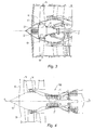
figure 3 représente une autre forme de réalisation de l'invention ; et - la
figure 4 représente une vue d'ensemble du turboréacteur de l'invention.
- the
figure 1 represents a sectional view of the upstream portion of a turbojet engine according to the invention with a current generator placed in the fan of the turbojet engine; - the
figure 2 represents a close-up view of the current generator of thefigure 1 ; - the
figure 3 represents another embodiment of the invention; and - the
figure 4 represents an overview of the turbojet engine of the invention.
En référence à la
Plus précisément, en référence à la
La soufflante 10,
La soufflante 10 comprend, en outre, un élément de capot mobile 11 qui vient se fixer sur le disque de soufflante 19. L'élément de capot mobile 11 est de forme tronconique et permet de guider la veine d'entrée d'air. Un élément de capot fixe 12 est disposé en amont de l'élément de capot mobile 11.The
La soufflante 10 est entraînée en rotation dans le carter de soufflante 14 par l'arbre de rotor BP 2 solidaire en rotation de l'élément de capot mobile 11. Un logement 13 est ménagé dans l'élément de capot mobile 11.The
En référence à la
L'élément rotorique 22 est ici un électroaimant s'étendant axialement selon l'axe X3. L'élément statorique 21 est composé d'enroulements qui s'étendent coaxialement et extérieurement à l'élément rotorique 22. Un palier 23 supporte en rotation l'élément rotorique 21 dans l'élément statorique 21.The
Lors de la rotation de l'électroaimant 22 autour de l'axe X3, un champ magnétique se créé et induit un courant électrique dans les enroulements 21.During the rotation of the
Des bras de maintien radiaux 16 relient structuralement l'élément de capot fixe 12 au carter de soufflante 14, l'élément statorique 21 du générateur de courant 20 demeurant ainsi immobile lors de la rotation des aubes de soufflante 18. Les bras de maintien 16 sont fixés par une bride sur le carter de soufflante 14.Radial holding
Les bras de maintien 16 sont avantageusement creux et permettent de loger des conduits 41 de lubrification du générateur de courant 20 et des câbles électriques 42 représentés sur la
Les conduits 41 de lubrification du générateur de courant 20 permettent d'acheminer un lubrifiant, tel que de l'huile, d'un réservoir d'huile, placé en aval de la soufflante, au générateur de courant 20 afin de permettre le refroidissement et la lubrification du générateur de courant 20.The
Après avoir refroidi le générateur de courant 20, de l'huile chaude circule dans les bras de maintien 16 permettant ainsi aux bras d'être dégivrés et à l'huile d'être refroidie. De tels conduits 41 de lubrifications permettent de diminuer la taille des échangeurs destinés à refroidir ladite huile.After cooling the
Les câbles électriques 42 permettent de conduire le courant généré dans les enroulements 21 vers des équipements électriques situés en aval du moteur.The
Les bras de maintien 16 de l'élément de capot fixe 12 sont ici profilés de manière à conduire la veine d'air d'entrée vers les aubes de soufflante 18. Les bras de maintien 16 sont ici au nombre de trois, espacés angulairement de 120 degrés. Il va de soi que ce nombre peut évoluer selon la configuration du moteur.The holding
Dans cet exemple de réalisation, l'élément rotorique 22 est directement relié à l'extrémité amont de l'arbre de rotor basse pression 2. Des pignons coniques de transmission de puissance 25, 26 sont respectivement formés sur l'élément rotorique 22 du générateur de courant 20 et sur l'extrémité amont de l'arbre de rotor basse pression 2, les pignons 25, 26 s'engrenant l'un avec l'autre pour transmettre le mouvement de rotation de l'arbre basse pression 2 à l'élément rotorique 22 du générateur de courant 20.In this embodiment, the
Lors du fonctionnement du turboréacteur 100, l'arbre de rotor basse pression 2 est entraîné en rotation par la turbine basse pression du turboréacteur 100.During operation of the
L'arbre de rotor basse pression 2 entraîne l'électroaimant 22 en rotation autour de l'axe X3 et induit un courant électrique dans les enroulements 21 du générateur de courant 20. Le courant est acheminé par les bras 16 de maintien de la l'élément de capot fixe 12 via les câbles électriques 42 disposées dans les bras 16, les équipements situés principalement en aval de la soufflante étant alors alimentés en courant électrique.The low-
Dans une autre forme de réalisation, en référence à la
Le tourillon 17 est relié par une liaison vis écrou au disque de soufflante 19 ainsi qu'à l'élément rotorique 22. La fixation du générateur de courant 20 avec l'élément de capot fixe 12 demeure identique ; seul le moyen d'entraînement de l'élément rotorique 22 diffère par rapport à la forme de réalisation précédente.The
L'invention concerne également le procédé de montage du générateur de courant 20 dans le turboréacteur 100.The invention also relates to the method of mounting the
On monte le générateur de courant 20 sur l'élément de capot fixe 12. Le générateur de courant 20 est ici vissé avec le capot.The
On dispose l'élément de capot fixe 12 sur la soufflante 10 de manière à ce que l'élément rotorique 22 du générateur 20 entre en correspondance avec l'extrémité amont de l'arbre du rotor basse pression 2.The
Le pignon conique de transmission de puissance 25 de l'élément statorique 22 est amené en correspondance avec le pignon conique de transmission de puissance 26 de l'arbre du rotor basse pression 2.The conical
On immobilise l'élément de capot fixe 12 sur le carter de soufflante 14 avec les bras de maintien radiaux 16.The fixed
Les conduits 41 de lubrification du générateur de courant 20 sont connectés au générateur de courant 20 afin d'approvisionner le générateur de courant 20 en huile, les câbles électriques 42 étant reliés aux enroulements de l'élément statorique 21 du générateur de courant 20 afin d'acheminer le courant aux différents équipements de l'aéronef.The
Claims (8)
Applications Claiming Priority (1)
| Application Number | Priority Date | Filing Date | Title |
|---|---|---|---|
| FR0705757A FR2919896B1 (en) | 2007-08-07 | 2007-08-07 | TURBOREACTOR COMPRISING A CURRENT GENERATOR MOUNTED IN THE BLOWER AND A METHOD FOR MOUNTING THE SAME GENERATOR IN THE SOUFFLANTE |
Publications (2)
| Publication Number | Publication Date |
|---|---|
| EP2022946A1 true EP2022946A1 (en) | 2009-02-11 |
| EP2022946B1 EP2022946B1 (en) | 2010-06-16 |
Family
ID=39357233
Family Applications (1)
| Application Number | Title | Priority Date | Filing Date |
|---|---|---|---|
| EP08161954A Active EP2022946B1 (en) | 2007-08-07 | 2008-08-06 | Jet engine comprising an electric generator mounted in the fan section and a method for mounting said generator in the fan section. |
Country Status (7)
| Country | Link |
|---|---|
| US (1) | US8026624B2 (en) |
| EP (1) | EP2022946B1 (en) |
| JP (1) | JP5378726B2 (en) |
| CA (1) | CA2638808C (en) |
| DE (1) | DE602008001537D1 (en) |
| FR (1) | FR2919896B1 (en) |
| RU (1) | RU2485328C2 (en) |
Cited By (4)
| Publication number | Priority date | Publication date | Assignee | Title |
|---|---|---|---|---|
| EP2412939A1 (en) * | 2010-07-30 | 2012-02-01 | Hamilton Sundstrand Corporation | Fan embedded power generator |
| EP2947278B1 (en) | 2014-05-20 | 2017-07-12 | United Technologies Corporation | Geared turbofan with high speed generator |
| US20220268871A1 (en) * | 2021-02-24 | 2022-08-25 | Bluehalo, Llc | System and method for a digitally beamformed phased array feed |
| US11955727B2 (en) | 2023-05-01 | 2024-04-09 | Bluehalo, Llc | System and method for a digitally beamformed phased array feed |
Families Citing this family (15)
| Publication number | Priority date | Publication date | Assignee | Title |
|---|---|---|---|---|
| DE102010014968A1 (en) | 2010-04-14 | 2011-10-20 | Mtu Aero Engines Gmbh | Multi-shaft engine with tandem generator |
| DE102010049885B4 (en) * | 2010-11-01 | 2015-06-25 | Rolls-Royce Deutschland Ltd & Co Kg | Jet engine |
| US9200592B2 (en) * | 2011-06-28 | 2015-12-01 | United Technologies Corporation | Mechanism for turbine engine start from low spool |
| US8723349B2 (en) | 2011-10-07 | 2014-05-13 | General Electric Company | Apparatus for generating power from a turbine engine |
| US8723385B2 (en) | 2011-10-07 | 2014-05-13 | General Electric Company | Generator |
| FR2989734B1 (en) * | 2012-04-24 | 2014-04-18 | Snecma | TURBOREACTOR INCORPORATING THERMOELECTRIC GENERATORS |
| CA2902461C (en) | 2013-03-14 | 2021-04-06 | Rolls-Royce Corporation | Hybrid turbo electric aero-propulsion system control |
| GB2526428A (en) * | 2014-04-15 | 2015-11-25 | Whoosh 2013 Ltd | Power generating Apparatus |
| FR3024755B1 (en) * | 2014-08-08 | 2019-06-21 | Safran Aircraft Engines | HYBRIDIZING THE COMPRESSORS OF A TURBOJET ENGINE |
| US10377498B2 (en) * | 2016-01-21 | 2019-08-13 | The Boeing Company | Aircraft and associated method for providing electrical energy to an anti-icing system |
| FR3054265B1 (en) * | 2016-07-22 | 2018-07-13 | Safran Aircraft Engines | TRAINING A ROTOR OF EQUIPMENT IN A TURBOMACHINE |
| US10308366B2 (en) * | 2016-08-22 | 2019-06-04 | General Electric Company | Embedded electric machine |
| US10071811B2 (en) * | 2016-08-22 | 2018-09-11 | General Electric Company | Embedded electric machine |
| US11156128B2 (en) | 2018-08-22 | 2021-10-26 | General Electric Company | Embedded electric machine |
| FR3087822B1 (en) * | 2018-10-26 | 2020-11-06 | Safran Aircraft Engines | TURBOMACHINE WITH ELECTRIC MACHINE INCLUDING A ROTOR RING HELD TO THE BLOWER |
Citations (7)
| Publication number | Priority date | Publication date | Assignee | Title |
|---|---|---|---|---|
| GB1174969A (en) | 1967-10-20 | 1969-12-17 | Rolls Royce | Gas Turbine Engine Provided with an Alternator |
| US3900274A (en) * | 1974-06-25 | 1975-08-19 | Gen Electric | Remote controlled actuation system for the rotor of a gas turbine engine |
| US5282719A (en) | 1991-05-13 | 1994-02-01 | Alliedsignal Inc. | Quad mode fan pitch actuation system for a gas turbine engine |
| EP1662636A2 (en) * | 2004-11-25 | 2006-05-31 | Snecma | Turbomachine with an integrated electrical generator |
| FR2882096A1 (en) | 2005-02-11 | 2006-08-18 | Snecma Moteurs Sa | Twin-shaft turbine engine for aircraft, has main drive pinion module driving movement transmission shafts extending coaxially, and driving unit comprising high and low pressure drive pinions integrated to high and low pressure rotors |
| GB2425572A (en) * | 2005-04-29 | 2006-11-01 | Gen Electric | Gas turbine starter-generator |
| WO2007036202A1 (en) | 2005-09-28 | 2007-04-05 | Mtu Aero Engines Gmbh | Jet engine comprising an integrated electric motor/generator unit |
Family Cites Families (14)
| Publication number | Priority date | Publication date | Assignee | Title |
|---|---|---|---|---|
| US4490622A (en) * | 1979-05-11 | 1984-12-25 | Osborn Norbert L | Turbocharger and adaptations thereof |
| EP0305763B1 (en) * | 1987-08-06 | 1991-07-10 | Mtu Motoren- Und Turbinen-Union MàNchen Gmbh | Energy-delivering installation |
| RU2014482C1 (en) * | 1990-12-29 | 1994-06-15 | Варюхин Александр Сергеевич | Device for control of gas-turbine engine thrust |
| IT1246759B (en) * | 1990-12-31 | 1994-11-26 | Sgs Thomson Microelectronics | INTEGRATED STRUCTURE OF BIPOLAR POWER TRANSISTOR AND LOW VOLTAGE BIPOLAR TRANSISTOR IN '' EMITTER SWITCHING '' OR '' SEMI-BRIDGE '' CONFIGURATIONS AND RELATED MANUFACTURING PROCESSES. |
| JP3244771B2 (en) * | 1992-06-04 | 2002-01-07 | 東海旅客鉄道株式会社 | Linear motor car |
| US5497615A (en) * | 1994-03-21 | 1996-03-12 | Noe; James C. | Gas turbine generator set |
| GB9606546D0 (en) * | 1996-03-28 | 1996-06-05 | Rolls Royce Plc | Gas turbine engine system |
| GB9904221D0 (en) * | 1999-02-25 | 1999-04-21 | Rolls Royce Plc | Gas turbine engine bearing arrangement |
| US20070199331A1 (en) * | 2003-09-19 | 2007-08-30 | Maguire Alan R | Power transmission arrangement |
| RU44148U1 (en) * | 2004-09-29 | 2005-02-27 | Открытое акционерное общество "Научно-производственное объединение "Сатурн" | GAS TURBINE ENGINE |
| US7134271B2 (en) * | 2004-11-05 | 2006-11-14 | General Electric Company | Thrust vectoring aft FLADE engine |
| IL165233A (en) * | 2004-11-16 | 2013-06-27 | Israel Hirshberg | Energy conversion device |
| US7948105B2 (en) * | 2007-02-01 | 2011-05-24 | R&D Dynamics Corporation | Turboalternator with hydrodynamic bearings |
| JP4648347B2 (en) * | 2007-02-23 | 2011-03-09 | 三菱重工業株式会社 | Hybrid exhaust turbine turbocharger |
-
2007
- 2007-08-07 FR FR0705757A patent/FR2919896B1/en not_active Expired - Fee Related
-
2008
- 2008-07-25 US US12/179,911 patent/US8026624B2/en active Active
- 2008-08-04 JP JP2008200449A patent/JP5378726B2/en active Active
- 2008-08-06 CA CA2638808A patent/CA2638808C/en active Active
- 2008-08-06 EP EP08161954A patent/EP2022946B1/en active Active
- 2008-08-06 DE DE602008001537T patent/DE602008001537D1/en active Active
- 2008-08-07 RU RU2008132629/06A patent/RU2485328C2/en active
Patent Citations (7)
| Publication number | Priority date | Publication date | Assignee | Title |
|---|---|---|---|---|
| GB1174969A (en) | 1967-10-20 | 1969-12-17 | Rolls Royce | Gas Turbine Engine Provided with an Alternator |
| US3900274A (en) * | 1974-06-25 | 1975-08-19 | Gen Electric | Remote controlled actuation system for the rotor of a gas turbine engine |
| US5282719A (en) | 1991-05-13 | 1994-02-01 | Alliedsignal Inc. | Quad mode fan pitch actuation system for a gas turbine engine |
| EP1662636A2 (en) * | 2004-11-25 | 2006-05-31 | Snecma | Turbomachine with an integrated electrical generator |
| FR2882096A1 (en) | 2005-02-11 | 2006-08-18 | Snecma Moteurs Sa | Twin-shaft turbine engine for aircraft, has main drive pinion module driving movement transmission shafts extending coaxially, and driving unit comprising high and low pressure drive pinions integrated to high and low pressure rotors |
| GB2425572A (en) * | 2005-04-29 | 2006-11-01 | Gen Electric | Gas turbine starter-generator |
| WO2007036202A1 (en) | 2005-09-28 | 2007-04-05 | Mtu Aero Engines Gmbh | Jet engine comprising an integrated electric motor/generator unit |
Cited By (17)
| Publication number | Priority date | Publication date | Assignee | Title |
|---|---|---|---|---|
| EP2412939A1 (en) * | 2010-07-30 | 2012-02-01 | Hamilton Sundstrand Corporation | Fan embedded power generator |
| US20120025676A1 (en) * | 2010-07-30 | 2012-02-02 | Poisson Richard A | Fan embedded power generator |
| US8522522B2 (en) * | 2010-07-30 | 2013-09-03 | Hamilton Sundstrand Corporation | Fan embedded power generator |
| EP2947278B1 (en) | 2014-05-20 | 2017-07-12 | United Technologies Corporation | Geared turbofan with high speed generator |
| US11236632B2 (en) | 2014-05-20 | 2022-02-01 | Raytheon Technologies Corporation | Geared turbofan with high speed generator |
| US20220268871A1 (en) * | 2021-02-24 | 2022-08-25 | Bluehalo, Llc | System and method for a digitally beamformed phased array feed |
| US11664594B2 (en) | 2021-02-24 | 2023-05-30 | Bluehalo, Llc | System and method for a digitally beamformed phased array feed |
| US11670855B2 (en) | 2021-02-24 | 2023-06-06 | Bluehalo, Llc | System and method for a digitally beamformed phased array feed |
| US11695209B2 (en) | 2021-02-24 | 2023-07-04 | Bluehalo, Llc | System and method for a digitally beamformed phased array feed |
| US11742579B2 (en) | 2021-02-24 | 2023-08-29 | Bluehalo, Llc | System and method for a digitally beamformed phased array feed |
| US11742578B2 (en) | 2021-02-24 | 2023-08-29 | Bluehalo, Llc | System and method for a digitally beamformed phased array feed |
| US11777215B2 (en) | 2021-02-24 | 2023-10-03 | Bluehalo, Llc | System and method for a digitally beamformed phased array feed |
| US11817636B2 (en) * | 2021-02-24 | 2023-11-14 | Bluehalo, Llc | System and method for a digitally beamformed phased array feed |
| US11824280B2 (en) | 2021-02-24 | 2023-11-21 | Bluehalo, Llc | System and method for a digitally beamformed phased array feed |
| US11843188B2 (en) | 2021-02-24 | 2023-12-12 | Bluehalo, Llc | System and method for a digitally beamformed phased array feed |
| US11870159B2 (en) | 2021-02-24 | 2024-01-09 | Bluehalo, Llc | System and method for a digitally beamformed phased array feed |
| US11955727B2 (en) | 2023-05-01 | 2024-04-09 | Bluehalo, Llc | System and method for a digitally beamformed phased array feed |
Also Published As
| Publication number | Publication date |
|---|---|
| FR2919896A1 (en) | 2009-02-13 |
| JP5378726B2 (en) | 2013-12-25 |
| US20090039653A1 (en) | 2009-02-12 |
| FR2919896B1 (en) | 2009-10-30 |
| DE602008001537D1 (en) | 2010-07-29 |
| US8026624B2 (en) | 2011-09-27 |
| EP2022946B1 (en) | 2010-06-16 |
| JP2009044956A (en) | 2009-02-26 |
| RU2008132629A (en) | 2010-02-20 |
| CA2638808A1 (en) | 2009-02-07 |
| CA2638808C (en) | 2015-06-23 |
| RU2485328C2 (en) | 2013-06-20 |
Similar Documents
| Publication | Publication Date | Title |
|---|---|---|
| EP2022946B1 (en) | Jet engine comprising an electric generator mounted in the fan section and a method for mounting said generator in the fan section. | |
| FR2922265A1 (en) | Ducted-fan and twin-spool turbine engine for aircraft, has current generator including permanent magnet rotor and stator that are centered on axis of motor, where rotor is driven by rotor shaft and stator is integrated to intermediate case | |
| EP1701019B1 (en) | Two-spool turbomachine with driving module on low pressure and high pressure rotors, driving module for the turbomachine and turbomachine assembly method | |
| CA2951196C (en) | A turbine engine comprising a drive system for a device such as an accessories case | |
| FR3054264A1 (en) | TURBOMACHINE WITH REDUCER WITH EPICYCLOIDAL TRAIN | |
| EP3870810B1 (en) | Fan module equipped with an electrical machine for a turbomachine of an aircraft | |
| FR2896537A1 (en) | TURBOMACHINE WITH INTEGRATED GENERATOR-STARTER | |
| CA2801680C (en) | Architecture for a non-lubricated turboshaft engine | |
| FR2920191A1 (en) | GAS TURBINE ENGINE WITH DRIVING MEANS FOR THE ACCESSORIES HOUSING AND METHOD OF MOUNTING THE SAME | |
| EP4069944B1 (en) | Electrical connection of an electrical machine in an aircraft turbine engine | |
| EP3394400B1 (en) | Turbojet engine with a means of transferring thrust on the inter-compressors casing | |
| EP3394401B1 (en) | Turbojet engine with thrust take-up means on the inter-compressor case | |
| FR2952121A1 (en) | Mechanical driving mechanism for driving high pressure body of engine i.e. turbojet, of airplane to control rotating part of airplane, has connection element utilized as drive socket of high pressure body | |
| FR3053077B1 (en) | ACCESSORIES RELAY HOUSING OF A TURBOMACHINE | |
| EP4069945B1 (en) | Rigid bar for electrically connecting a machine in an aircraft turbine engine | |
| FR3021296A1 (en) | DUAL PROPELLER PROPELLER ASSEMBLY FOR AIRCRAFT | |
| FR3055354B1 (en) | TURBOMACHINE COMPRISING MEANS FOR SEALING AND METHOD FOR MOUNTING THE CORRESPONDING TURBOMACHINE | |
| WO2015075348A1 (en) | Lubrication device for a turbine engine | |
| EP3870812B1 (en) | Aircraft turbomachine equipped with an electrical machine | |
| EP4267839A1 (en) | Turbomachine module equipped with an electric machine and turbomachine equipped with such a module | |
| FR3092140A1 (en) | Improved turbomachine comprising an inertial system. | |
| FR3055308A1 (en) | MEANS FOR CONTROLLING A STEERING CHANGE SYSTEM COMPRISING AN ANTI-ROTATION DEVICE, A SHIFT SYSTEM EQUIPPED WITH SAID CONTROL MEANS AND CORRESPONDING TURBOMACHINE |
Legal Events
| Date | Code | Title | Description |
|---|---|---|---|
| PUAI | Public reference made under article 153(3) epc to a published international application that has entered the european phase |
Free format text: ORIGINAL CODE: 0009012 |
|
| 17P | Request for examination filed |
Effective date: 20080806 |
|
| AK | Designated contracting states |
Kind code of ref document: A1 Designated state(s): AT BE BG CH CY CZ DE DK EE ES FI FR GB GR HR HU IE IS IT LI LT LU LV MC MT NL NO PL PT RO SE SI SK TR |
|
| AX | Request for extension of the european patent |
Extension state: AL BA MK RS |
|
| RTI1 | Title (correction) |
Free format text: JET ENGINE COMPRISING AN ELECTRIC GENERATOR MOUNTED IN THE FAN SECTION AND A METHOD FOR MOUNTING SAID GENERATOR IN THE FAN SECTION. |
|
| AKX | Designation fees paid |
Designated state(s): DE FR GB IT SE |
|
| GRAP | Despatch of communication of intention to grant a patent |
Free format text: ORIGINAL CODE: EPIDOSNIGR1 |
|
| GRAS | Grant fee paid |
Free format text: ORIGINAL CODE: EPIDOSNIGR3 |
|
| GRAA | (expected) grant |
Free format text: ORIGINAL CODE: 0009210 |
|
| AK | Designated contracting states |
Kind code of ref document: B1 Designated state(s): DE FR GB IT SE |
|
| REF | Corresponds to: |
Ref document number: 602008001537 Country of ref document: DE Date of ref document: 20100729 Kind code of ref document: P |
|
| REG | Reference to a national code |
Ref country code: SE Ref legal event code: TRGR |
|
| PLBE | No opposition filed within time limit |
Free format text: ORIGINAL CODE: 0009261 |
|
| STAA | Information on the status of an ep patent application or granted ep patent |
Free format text: STATUS: NO OPPOSITION FILED WITHIN TIME LIMIT |
|
| 26N | No opposition filed |
Effective date: 20110317 |
|
| REG | Reference to a national code |
Ref country code: DE Ref legal event code: R097 Ref document number: 602008001537 Country of ref document: DE Effective date: 20110316 |
|
| REG | Reference to a national code |
Ref country code: FR Ref legal event code: PLFP Year of fee payment: 8 |
|
| REG | Reference to a national code |
Ref country code: FR Ref legal event code: PLFP Year of fee payment: 9 |
|
| REG | Reference to a national code |
Ref country code: FR Ref legal event code: PLFP Year of fee payment: 10 |
|
| REG | Reference to a national code |
Ref country code: FR Ref legal event code: CD Owner name: SAFRAN AIRCRAFT ENGINES, FR Effective date: 20170719 |
|
| REG | Reference to a national code |
Ref country code: FR Ref legal event code: PLFP Year of fee payment: 11 |
|
| PGFP | Annual fee paid to national office [announced via postgrant information from national office to epo] |
Ref country code: IT Payment date: 20230720 Year of fee payment: 16 Ref country code: GB Payment date: 20230720 Year of fee payment: 16 |
|
| PGFP | Annual fee paid to national office [announced via postgrant information from national office to epo] |
Ref country code: SE Payment date: 20230720 Year of fee payment: 16 Ref country code: FR Payment date: 20230720 Year of fee payment: 16 Ref country code: DE Payment date: 20230720 Year of fee payment: 16 |