EP2055613A2 - Electric power steering apparatus - Google Patents
Electric power steering apparatus Download PDFInfo
- Publication number
- EP2055613A2 EP2055613A2 EP08167848A EP08167848A EP2055613A2 EP 2055613 A2 EP2055613 A2 EP 2055613A2 EP 08167848 A EP08167848 A EP 08167848A EP 08167848 A EP08167848 A EP 08167848A EP 2055613 A2 EP2055613 A2 EP 2055613A2
- Authority
- EP
- European Patent Office
- Prior art keywords
- torque
- steering
- assist
- gradient
- control
- Prior art date
- Legal status (The legal status is an assumption and is not a legal conclusion. Google has not performed a legal analysis and makes no representation as to the accuracy of the status listed.)
- Granted
Links
Images


Classifications
-
- B—PERFORMING OPERATIONS; TRANSPORTING
- B62—LAND VEHICLES FOR TRAVELLING OTHERWISE THAN ON RAILS
- B62D—MOTOR VEHICLES; TRAILERS
- B62D5/00—Power-assisted or power-driven steering
- B62D5/04—Power-assisted or power-driven steering electrical, e.g. using an electric servo-motor connected to, or forming part of, the steering gear
- B62D5/0457—Power-assisted or power-driven steering electrical, e.g. using an electric servo-motor connected to, or forming part of, the steering gear characterised by control features of the drive means as such
- B62D5/046—Controlling the motor
- B62D5/0463—Controlling the motor calculating assisting torque from the motor based on driver input
-
- B—PERFORMING OPERATIONS; TRANSPORTING
- B62—LAND VEHICLES FOR TRAVELLING OTHERWISE THAN ON RAILS
- B62D—MOTOR VEHICLES; TRAILERS
- B62D5/00—Power-assisted or power-driven steering
- B62D5/04—Power-assisted or power-driven steering electrical, e.g. using an electric servo-motor connected to, or forming part of, the steering gear
- B62D5/0457—Power-assisted or power-driven steering electrical, e.g. using an electric servo-motor connected to, or forming part of, the steering gear characterised by control features of the drive means as such
- B62D5/046—Controlling the motor
- B62D5/0466—Controlling the motor for returning the steering wheel to neutral position
Definitions
- This invention relates to an electric power steering (EPS) apparatus.
- EPS electric power steering
- EPS apparatuses using a motor as a drive source have been used as power steering units for vehicles.
- a variety of suggestions have been made to realize better steering feeling in the EPS by using high controllability thereof.
- JP-A-2006-131191 discloses a configuration in which characteristics of each compensation control are changed based on a ratio (assist gradient) of a variation of a basic assist component to a variation of a steering torque.
- the EPS usually executes an operation of providing an assist force corresponding to a steering torque detected based on a torsion angle of a torsion bar provided at the steering shaft, and the variation of the assist gradient is equivalent to the variation of a spring constant of the torsion bar.
- This configuration makes it possible to realize good steering feeling by optimizing the characteristics of each compensation control according to the variation of such basic steering characteristics.
- the EPS features a degree of freedom in layout selection that is higher and an energy consumption amount that is lower than those of hydraulic power steering apparatuses.
- the EPS systems have been finding ever growing application to vehicles with a small load on a front shaft of the vehicle, such as small automobiles and the so-called mid-ship vehicles.
- a problem associated therewith is that a response feeling during steering, that is, a steering reaction force, is often insufficient.
- a configuration has been disclosed (see, for example, Japanese Patent Application Publication No. 2002-293256 ( JP-A-2002-293256 )) in which a steering reaction force component in the direction opposite that of the steering operation is superimposed on the basic assist component.
- better steering feeling can be also realized by introducing a feedback control when the steering reaction force component is computed.
- the invention was created to resolve the above-described problems, and it is an object of the invention to provide an EPS apparatus that can realize good steering feeling with good stability.
- the first aspect of the invention relates to an EPS apparatus including: a steering force assist device that provides an assist force for assisting a steering operation to a steering system by using a motor as a drive source, and a controller that controls an operation of the steering force assist device.
- the controller computes a fundamental component of the assist force to be generated in the steering force assist device based on a steering torque, and superimposes on the fundamental component a steering reaction force component that is computed by executing a torque feedback control based on a difference between a target steering reaction force and the steering torque, which is an actual steering reaction force.
- the controller executes a compensation control based on an assist gradient, which is a ratio of a variation of the fundamental component to a variation of the steering torque when the torque feedback control is not executed.
- the controller executes the compensation control based on a value obtained by adding a feedback gain gradient, which is a ratio of a variation of the steering reaction force component to a variation of the difference in the torque feedback control, to the assist gradient when the torque feedback
- the variation amount of an assist force (target assist force) that has to be generated by the steering force assist device when the torque feedback control is executed uses as a base a sum total of the variation amount of the fundamental component and the variation amount of the steering reaction force component, both being based on the steering torque.
- a ratio of the variation of the target assist force to the variation of the steering torque ⁇ assumes a value close to a value obtained by adding up the assist gradient and the feedback gain gradient. Therefore, by executing the assist gradient compensation control by using the sum obtained, as in the above-described configuration, it is possible to optimize each compensation control with high accuracy even during the torque feedback control. As a result, good steering feeling can be realized with good stability.
- the controller may limit the steering reaction force component and does not add the feedback gain gradient to the assist gradient for the compensation control when the steering reaction force component is limited.
- each compensation control can be optimized with better stability.
- the controller may compute the fundamental component of the assist force based on the steering torque that is detected by a torque sensor and which is subjected to a phase compensation processing, and the steering reaction force component is limited based on a steering torque which the phase compensation processing is not subjected.
- the object of limiting the steering reaction force component is to inhibit an extremely large steering reaction force in each instant, but the phase of the steering torque after the phase compensation processing is shifted from that of the steering torque serving as a detection signal outputted by the torque sensor.
- the instant for which the correction is truly necessary is not captured accurately.
- a steering torque prior to phase compensation which is a detection signal outputted by the torque sensor, as in the above-described aspect, it is possible to capture accurately the instant for which the correction is truly necessary and to execute the limitation of the steering reaction force component with higher accuracy.
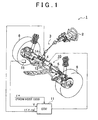
- FIG. 1 is a schematic diagram of an EPS 1 of the present embodiment.
- a steering shaft 3 having a steering wheel (steering) 2 fixed thereto is linked to a rack 5 via a rack-and-pinion mechanism 4, and the rotation of the steering shaft 3 following the steering operation is converted by the rack-and-pinion mechanism 4 into the reciprocal linear movement of the rack 5.
- the reciprocal linear movement of the rack 5 changes the steering angle of the drive wheels 6.
- the EPS 1 includes an EPS actuator 10 as a steering force assist device that provides an assist force for assisting the steering operation to a steering system and an ECU 11 serving as a controller for controlling the operation of the EPS actuator 10.
- the EPS actuator 10 of the present embodiment is an EPS actuator of the so-called rack type in which a motor 12, which is a drive source, is disposed coaxially with the rack 5.
- the assist torque generated by the motor 12 is transmitted to the rack 5 via a ball screw mechanism (not shown in the figure).
- the motor 12 of the present embodiment is a brushless motor that revolves by receiving a three-phase (U, V, W) drive power supply from the ECU 11.
- the ECU 11 serving as a motor control device controls the assist force provided to the steering system by controlling the assist torque generated by the motor 12 (power assist control).
- a torque sensor 14 and a vehicle speed sensor 15 are connected to the ECU 11.
- a torque sensor of the so-called twin-resolver type that detects a torsion angle of a torsion bar provided in the intermediate section of the steering shaft 3 by a pair of angle sensors (resolvers) is employed as the torque sensor 14.
- the ECU 11 executes the actuation of an EPS actuator 10, that is, power assist control based on a steering torque ⁇ ( ⁇ _na) and vehicle speed V detected by the torque sensor 14 and vehicle speed sensor 15, respectively.
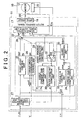
- FIG. 2 is a control block diagram of the EPS of the present embodiment.
- the ECU 11 includes a microcomputer 17 serving as a motor control signal output means for outputting a motor control signal and a drive circuit 18 that supplies a three-phase drive power to the motor 12 based on the motor control signal.
- a current sensor 20 for detecting an actual current value I supplied to the motor 12 and a revolution angle sensor 21 for detecting a motor revolution angle ⁇ m of the motor 12 are connected to the ECU 11.
- the microcomputer 17 generates a motor control signal that is outputted to a drive circuit 18 based on the vehicle state parameters and also the actual current value I and motor revolution angle ⁇ m detected based on the output signals of the current sensor 20 and revolution angle sensor 21.
- the microcomputer 17 includes a current command value computation unit 22 that computes a target value of the assist force provided to the steering system, that is, a current command value Iq* corresponding to the target assist force, and a motor control signal output unit 23 that outputs a motor control signal based on the current command value Iq* computed by the current command value computation unit 22.
- the current command value Iq* outputted by the current command value computation unit 22 is inputted, together with the actual current value I detected by the current sensor 20 and the motor revolution angle ⁇ m detected by the revolution angle sensor 21 to the motor control signal output unit 23.
- the motor control signal output unit 23 computes a motor control signal by executing the feedback control designed to cause the actual current value I to follow the current command value Iq* corresponding to the target assist force.
- a brushless motor that revolves when a three-phase (U, V, W) drive power is supplied thereto is used as the motor 12.
- the motor control signal output unit 23 performs the current feedback control by converting the phase current values (Iu, Iv, Iw) of the motor 12 detected as the actual current value I into the d-, q-axis current values (d/q conversion) of the d/q coordinate system.
- the current command value Iq* is inputted as a q-axis current command value into the motor control signal output unit 23, and the motor control signal output unit 23 performs the d/q conversion of the phase current values (Iu, Iv, Iw) based on the motor revolution angle ⁇ m detected by the revolution angle sensor 21. Furthermore, the motor control signal output unit 23 also computes the d-, q-axis voltage command values based on the d-, q-axis current values and q-axis current command value. Phase voltage command values (Vu*, Vv*, Vw*) are then computed by d/q reverse conversion of the d-, q-axis voltage command values, and a motor control signal is generated based on the phase voltage command values.
- the ECU 11 of the present embodiment is configured so that the motor control signal generated in the above-described manner is outputted by the microcomputer 17 to the drive circuit 18, and the drive circuit 18 supplies a three-phase drive power based on this motor control signal to the motor 12, thereby controlling the operation of the EPS actuator 10.
- the current command value computation unit 22 of the present embodiment includes a basic assist control unit 25 that computes a basic assist control value Ias*, which is a fundamental component of the assist force that has to be generated by the EPS actuator 10, and a torque inertia compensation control unit 26 that computes a torque inertia compensation amount Iti* based on a differential value (steering torque differential value d ⁇ ) of the steering torque ⁇ .
- a basic assist control unit 25 that computes a basic assist control value Ias*, which is a fundamental component of the assist force that has to be generated by the EPS actuator 10
- a torque inertia compensation control unit 26 that computes a torque inertia compensation amount Iti* based on a differential value (steering torque differential value d ⁇ ) of the steering torque ⁇ .
- the steering torque ⁇ _na serving as a detection signal outputted by the torque sensor 14 is inputted into a phase compensation control unit 27. Then, the steering torque ⁇ after the implementation of the phase compensation processing in the phase compensation control unit 27 and vehicle speed V are inputted to the basic assist control unit 25.
- the basic assist control unit 25 computes the basic assist control value Ias* having an absolute value that increases with the increase in the absolute value of the steering torque ⁇ and with the decrease in the vehicle speed V. Further, the design is such that in the relation with the steering torque ⁇ , an assist gradient Ra, which is a ratio of the variation of the basic assist control value Ias* to the variation of the steering torque ⁇ , increases with the increase in the steering torque ⁇ .
- the vehicle speed V is inputted, in addition to the steering torque differential value d ⁇ , into the torque inertia compensation control unit 26 of the present embodiment.
- the torque inertia compensation control unit 26 then executes the torque inertia compensation control based on these state parameters.
- the "torque inertia compensation control” is a control that is performed to compensate the effect of EPS inertia, that is, a control serving to inhibit "a resistance feel (tracking delay)" at the "start of disconnection” and “a flow feel (overshoot)” at the "end of disconnection” in the steering operation.
- Such torque inertia compensation control is also effective in inhibiting the vibrations generated in the steering system by the application of a reverse input stress to the drive wheels 6.
- the torque inertia compensation control unit 26 includes a map 26a in which the steering torque differential value d ⁇ is associated with a fundamental compensation amount ⁇ ti, and a map 26b in which the vehicle speed V is associated with an interpolation coefficient A.
- the fundamental compensation amount ⁇ ti is set to assume a value that further increases the basic assist control value Ias* (absolute value thereof) computed in the basic assist control unit 25 with the increase in the absolute value of the inputted steering torque differential value d ⁇ .
- the interpolation coefficient A is set to assume a value that increases with the increase in the vehicle speed V in a low-speed region and decrease with the increase in vehicle speed in a high-speed region.
- the torque inertia compensation control unit 26 computes the torque inertia compensation amount Iti* by multiplying the fundamental inertia amount ⁇ ti and the interpolation coefficient A found with reference to these maps 26a, 26b.
- microcomputer 17 changes the characteristics of each compensation control based on the assist gradient Ra whose value changes correspondingly to the steering torque ⁇ detected in the above-described manner.
- an assist gradient compensation control unit 28 is provided in the current command value computation unit 22 of the present embodiment, and the assist gradient Ra inputted from the basic assist control unit 25 into the assist gradient compensation control unit 28 is inputted via the below-described switching control unit 32 into a filter constant computation unit 30 and an assist gradient gain computation unit 31. Further, in the present embodiment, a filter constant Af computed in the filter constant computation unit 30 is outputted to the phase compensation control unit 27, and an assist gradient gain Ka computed in the assist gradient computation unit 31 is outputted to the torque inertia compensation control unit 26, thereby changing the characteristics of the phase compensation control and torque inertia compensation control.
- the variation of the assist gradient Ra is equivalent to the variation of the spring constant of the torsion bar provided in the intermediate portion of the steering shaft 3. Therefore, the vibrations tend to occur easier when the assist gradient Ra increases, but the problem of vibrations increasing with the increase in the assist gradient Ra can be resolved by inhibiting the variations in the characteristics of the phase compensation control, more specifically by inhibiting the gain of filter characteristics in the phase compensation processing. Further, the increase in vibrations accompanying the increase in assist gradient Ra is inhibited by outputting the filter constant Af such that decreases the gain of filter characteristic in response to increase in the assist gradient Ra such as shown in FIG. 5 , from the assist gradient compensation control unit 28 to the phase compensation control unit 27.
- the basic assist control amount Ias* computed in the basic assist control unit 25 and the torque inertia compensation amount Iti* computed in the torque inertia compensation control unit 26 are inputted into an adder 29.
- the current command value computation unit 22 outputs a value obtained by the addition in the adder 29 as a current command value Iq* to the motor control signal output unit 23.
- the current command value computation unit 22 includes a torque F/B control unit 33 in addition to the above-described control units.
- a torque F/B control amount Iftb* (Iftb**) serving as a steering reaction force component for adding a reaction force torque in the direction (return direction) opposite that of the steering angle to the steering 2 computed in the torque F/B control unit 33 is inputted into the adder 29.
- a value obtained by superimposing the torque F/B control amount Iftb** on the basic assist control amount Ias* (and torque inertia compensation amount Iti*) is outputted as the current command value Iq* to the motor control signal output unit 23.
- a steering torque target value ⁇ * serving as a target steering resistant force is inputted from a host ECU (not shown in the figure) to the ECU 11 (see FIG. 1 ), and a difference ⁇ between the steering torque target value ⁇ * serving as a target steering resistance force and the steering torque ⁇ serving as an actual steering reaction force is inputted to the torque F/B control unit 33.
- the torque F/B control unit 33 computes the torque F/B control amount Iftb* by executing the torque feedback control based on this difference ⁇ , more specifically, by multiplying the difference ⁇ by a predetermined feedback gain.
- the current command value computation unit 22 limits the torque F/B control amount Iftb* inputted to the adder 29 so as to prevent the application of an excessively high steering reaction force and the occurrence of the so-called self-steer.
- the current command value computation unit 22 is provided with a torque gain computation unit 34, and the torque gain computation unit 34 computes the torque gain K ⁇ for reducing the torque F/B control amount Iftb* correspondingly to the steering torque inputted to the steering 2 (see FIG. 7 ).
- a steering torque before the phase compensation process is performed in the phase compensation control unit 27, that is, the steering torque ⁇ _na serving as a detection signal outputted by the torque sensor 14, is inputted to the torque gain computation unit 34.
- the torque F/B control amount Iftb* outputted by the torque F/B control unit 33 is multiplied by the torque gain K ⁇ computed by the torque gain computation unit 34.
- the current command value computation unit 22 includes a guard processing unit 35, and the torque F/B control amount Iftb* outputted from the torque F/B control unit 33 is inputted to the guard processing unit 35 after being multiplied by the torque gain K ⁇ as described hereinabove.
- the torque F/B control amount Iftb** that has been confined to a predetermined range by the guard processing in the guard processing unit 35 is inputted to the adder 29.
- the execution of the torque feedback control also changes the apparent spring constant of the torsion bar.
- the optimization of each compensation control can be impossible even if the assist gradient compensation control identical to that of the usual mode is executed.
- the attention is paid to the ratio of the steering reaction force component (torque F/B control amount Iftb**) to a variation of the steering reaction force difference ( ⁇ ) in the torque feedback control, that is, to the feedback gain gradient (F/B gain gradient Rp).
- torque F/B control amount Iftb** a variation of the steering reaction force difference ( ⁇ ) in the torque feedback control
- F/B gain gradient Rp the feedback gain gradient
- the variation amount of the current command value Iq* outputted by the current command value computation unit 22 when the torque feedback control is executed uses as a base a sum total of the variation amount of the basic assist control amount Ias* and the variation amount of the torque F/B control amount Iftb**, both being based on the steering torque ⁇ . Therefore, a ratio of the variation of the current command value Iq* to the variation of the steering torque ⁇ inputted to the current command value computation unit 22 approaches the sum of the assist gradient Ra and the F/B gain gradient Rp, and by executing the assist gradient compensation control by using the sum (Ra + Rp) obtained, it is possible to optimize each compensation control with high accuracy.
- the assist gradient Ra is inputted from the basic assist control unit 25 to the assist gradient compensation control unit 28, and the F/G gain gradient Rp is also inputted from the torque F/B control unit 33 to the assist gradient compensation control unit 28.
- the feedback gain used for the torque feedback control in the torque F/B control unit 33 is a predetermined value. Therefore, the F/B gain gradient Rp is also a constant value.
- the F/B gain gradient Rp inputted to the assist gradient compensation control unit 28 is added to the assist gradient Ra in the adder 36, and the sum obtained is inputted to the switching control unit 32.
- the assist gradient Ra that has been inputted from the basic assist control unit 25 is directly inputted together with the sum (Ra + Rp) to the switching control unit 32.
- the switching control unit 32 outputs the sum (Ra + Rp) of the assist gradient Ra and F/B gain gradient Rp, instead of the assist gradient Ra, to the filter constant computation unit 30 and assist gradient gain computation unit 31.
- the torque F/B control amount Iftb** after the guard treatment in the guard treatment unit 35 is inputted to the switching control unit 32, and the switching control unit 32 executes the output switching based on the inputted torque F/B control amount Iftb**.
- the switching control unit 32 acquires the torque F/B control amount Iftb** (step 101)
- the switching control unit determines based on the torque F/B control amount Iftb** whether the torque feedback control is OFF or whether the guard operation is implemented (step 102).
- the guard treatment yields a state in which the outputted torque F/B control amount Iftb** is an upper-limit or lower-limit constant value. Further, when the torque F/B control amount Iftb** is almost zero, it is determined that "the torque feedback control is OFF".
- step 102: NO the switching control unit 32 outputs a sum (Ra + Rp) of the assist gradient Ra and the F/B gain gradient Rp (step 103), and when any of the conditions is met (step 102: YES), the switching control unit 32 outputs the assist gradient Ra (step 104).
- the filter constant computation unit 30 and assist gradient gain computation unit 31 execute the computation of the filter constant Af and the computation of the assist gradient gain Ka, respectively, based on the assist gradient Ra or sum (Ra + Rp) outputted by the switching control unit 32, thereby ensuring the optimization of each compensation control, regardless of whether or not the torque feedback control is executed.
- the assist gradient Ra is inputted to the assist gradient compensation control unit 28, and the F/B gain gradient Rp is also inputted thereto.
- the F/B gain gradient Rp is added to the assist gradient Ra in the adder 36 and the sum obtained is inputted to the switching control unit 32.
- the assist gradient Ra that has been inputted from the basic assist control unit 25 is directly inputted together with the sum (Ra + Rp) to the switching control unit 32.
- the switching control unit 32 outputs the sum (Ra + Rp) of the assist gradient Ra and F/B gain gradient Rp to the filter constant computation unit 30 and assist gradient gain computation unit 31.
- the variation amount of the current command value Iq* outputted by the current command value computation unit 22 when the torque feedback control is executed uses as a base a sum total of the variation amount of the basic assist control amount Ias* and the variation amount of the torque F/B control amount Iftb**, both being based on the steering torque ⁇ . Therefore, a ratio of the variation of the current command value Iq* to the variation of the steering torque ⁇ inputted to the current command value computation unit 22 approaches the sum of the assist gradient Ra and the F/B gain gradient Rp. Therefore, with the above-described configuration, by executing the assist gradient compensation control by using the sum (Ra + Rp), it is possible to optimize each compensation control with high accuracy even during the torque feedback control. As a result, good steering feeling can be realized with good stability.
- the current command value computation unit 22 includes the guard processing unit 35, and the torque F/B control amount Iftb* outputted from the torque F/B control unit 33 is confined to a predetermined range by the guard processing in the guard processing unit 35. Further, the torque F/B control amount Iftb** after the guard processing has been implemented in the guard processing unit 35 is inputted to the switching control unit 32. Based on the torque F/B control amount Iftb**, the switching control unit determines whether the torque feedback control is OFF or whether the guard operation is implemented. If any of these conditions is met, the assist gradient Ra is directly outputted without the addition of the F/B gain gradient Rp.
- the current control value computation unit 22 includes the torque gain computation unit 34, and the torque gain computation unit 34 computes the torque gain K ⁇ for reducing the torque F/B control amount Iftb* correspondingly to the steering torque inputted to the steering 2.
- the computation of the torque gain K ⁇ in the torque gain computation unit 34 is executed based on the steering torque before the phase compensation process is performed in the phase compensation control unit 27, that is, the steering torque ⁇ _na serving as a detection signal outputted by the torque sensor 14.
- the object of computing the torque gain K ⁇ is to inhibit an extremely large steering reaction force in each instant, but the phase of the steering torque ⁇ after the phase compensation processing is shifted from that of the steering torque ⁇ _na serving as a detection signal outputted by the torque sensor 14. In other words, the instant for which the correction is truly necessary is not captured accurately.
- the steering torque ⁇ _na serving as a detection signal outputted by the torque sensor 14 it is possible to capture accurately the instant for which the correction is truly necessary and to execute the torque gain computations with higher accuracy.
- the present embodiment may be modified in the manner as follows.
- it is determined whether the torque feedback control is OFF or whether the guard operation is implemented, and when any of these conditions is met, the assist gain compensation control is implemented based directly on the assist gradient Ra, without adding the F/B gain gradient Rp.
- the assist gain compensation control is implemented based directly on the assist gradient Ra, without adding the F/B gain gradient Rp.
- such a configuration is not limiting. For example, it is possible only to determine whether the guard operation is implemented, without determining whether the torque feedback control is OFF. Alternatively, a configuration in which none of these two conditional determination operations is performed may be employed.
- the assist gradient compensation control with respect to the phase compensation processing executed by the phase compensation control unit 27 is performed by reducing the gain of the filter characteristic in the phase compensation processing as the assist gradient Ra rises.
- a configuration is not limiting, and a configuration may be employed in which the filter characteristic is changed from the standpoint of the phase advance/delay.
- the assist gradient compensation control is performed with respect to the phase compensation control relating to the steering torque and the torque inertia compensation control based on the steering torque differential value d ⁇ , as compensation control operations, but the assist gradient compensation control may be performed with respect to another compensation control, for example, a steering return control based on a steering angle (motor revolution angle).
- the controller superimposes the compensation component that is based on the differential value of the steering torque on the fundamental component and changes the computation characteristic of the compensation component that is based on the differential value of the steering torque on the basis of the assist gradient.
- An assist gradient Ra and also an F/B gain gradient Rp are inputted to an assist gradient compensation control unit (28).
- the F/B gradient Rp is added to the assist gradient Ra in an adder (36) and the sum obtained is inputted into a switching control unit (32).
- the assist gradient Ra that has been inputted from a basic assist control unit (25) is directly inputted together with the sum (Ra + Rp) to the switching control unit (32).
- the switching control unit (32) outputs the sum (Ra + Rp) of the assist gradient Ra and F/B gain gradient Rp to a filter constant computation unit 30 and an assist gradient gain computation unit (31).
Abstract
Description
- This invention relates to an electric power steering (EPS) apparatus.
- EPS apparatuses using a motor as a drive source have been used as power steering units for vehicles. A variety of suggestions have been made to realize better steering feeling in the EPS by using high controllability thereof.
- For example, Japanese Patent Application Publication No.
2006-131191 JP-A-2006-131191 - Further, the EPS features a degree of freedom in layout selection that is higher and an energy consumption amount that is lower than those of hydraulic power steering apparatuses. For this reason, the EPS systems have been finding ever growing application to vehicles with a small load on a front shaft of the vehicle, such as small automobiles and the so-called mid-ship vehicles. However, although such vehicles feature a small motor torque, a problem associated therewith is that a response feeling during steering, that is, a steering reaction force, is often insufficient. Accordingly, a configuration has been disclosed (see, for example, Japanese Patent Application Publication No.
2002-293256 JP-A-2002-293256 - However, a problem arises when the above-described two conventional configurations are used together. Thus, the execution of the torque feedback control changes an apparent spring constant of the torsion bar. As a result, it is impossible to optimize each compensation control by simply combining the two configurations and, therefore, the control stability and steering feeling are degraded.
- The invention was created to resolve the above-described problems, and it is an object of the invention to provide an EPS apparatus that can realize good steering feeling with good stability.
- The first aspect of the invention relates to an EPS apparatus including: a steering force assist device that provides an assist force for assisting a steering operation to a steering system by using a motor as a drive source, and a controller that controls an operation of the steering force assist device. The controller computes a fundamental component of the assist force to be generated in the steering force assist device based on a steering torque, and superimposes on the fundamental component a steering reaction force component that is computed by executing a torque feedback control based on a difference between a target steering reaction force and the steering torque, which is an actual steering reaction force. The controller executes a compensation control based on an assist gradient, which is a ratio of a variation of the fundamental component to a variation of the steering torque when the torque feedback control is not executed. The controller executes the compensation control based on a value obtained by adding a feedback gain gradient, which is a ratio of a variation of the steering reaction force component to a variation of the difference in the torque feedback control, to the assist gradient when the torque feedback control is executed.
- Thus, the variation amount of an assist force (target assist force) that has to be generated by the steering force assist device when the torque feedback control is executed uses as a base a sum total of the variation amount of the fundamental component and the variation amount of the steering reaction force component, both being based on the steering torque. As a result, a ratio of the variation of the target assist force to the variation of the steering torque τ assumes a value close to a value obtained by adding up the assist gradient and the feedback gain gradient. Therefore, by executing the assist gradient compensation control by using the sum obtained, as in the above-described configuration, it is possible to optimize each compensation control with high accuracy even during the torque feedback control. As a result, good steering feeling can be realized with good stability.
- In the first aspect, the controller may limit the steering reaction force component and does not add the feedback gain gradient to the assist gradient for the compensation control when the steering reaction force component is limited.
- Thus, when the steering reaction force component is constant, regardless of the steering torque variations, limiting the steering reaction force component makes it possible to ignore the effect produced by the execution of the torque feedback control on "the apparent spring constant of the torsion bar". Therefore, with this configuration, each compensation control can be optimized with better stability.
- In the first aspect, the controller may compute the fundamental component of the assist force based on the steering torque that is detected by a torque sensor and which is subjected to a phase compensation processing, and the steering reaction force component is limited based on a steering torque which the phase compensation processing is not subjected.
- Thus, the object of limiting the steering reaction force component is to inhibit an extremely large steering reaction force in each instant, but the phase of the steering torque after the phase compensation processing is shifted from that of the steering torque serving as a detection signal outputted by the torque sensor. In other words, the instant for which the correction is truly necessary is not captured accurately. However, by using a steering torque prior to phase compensation, which is a detection signal outputted by the torque sensor, as in the above-described aspect, it is possible to capture accurately the instant for which the correction is truly necessary and to execute the limitation of the steering reaction force component with higher accuracy.
- With the above-described aspect of the invention, it is possible to provide an EPS apparatus that can realize good steering feeling with good stability.
- The features, advantages, and technical and industrial significance of this invention will be described in the following detailed description of example embodiments of the invention with reference to the accompanying drawings, in which like numerals denote like elements, and wherein:
-
FIG 1 shows a schematic configuration of an EPS apparatus; -
FIG 2 is a control block diagram of the EPS in the present embodiment; -
FIG 3 is an explanatory drawing illustrating the main features of the basic assist control computation and assist gradient; -
FIG. 4 is a control block diagram of the torque inertia compensation control unit; -
FIG. 5 is an explanatory drawing illustrating the mode of assist gradient compensation control with respect to the phase compensation processing; -
FIG. 6 is an explanatory drawing illustrating the relationship between the assist gradient and assist gradient gain; -
FIG. 7 is an explanatory drawing illustrating the relationship between a steering torque and a steering torque gain; and -
FIG. 8 is a flowchart illustrating the processing sequence of output switching performed in the switching control unit. - An embodiment of the invention will be explained below with reference to the appended drawings.
FIG. 1 is a schematic diagram of anEPS 1 of the present embodiment. As shown in the figure, a steering shaft 3 having a steering wheel (steering) 2 fixed thereto is linked to arack 5 via a rack-and-pinion mechanism 4, and the rotation of the steering shaft 3 following the steering operation is converted by the rack-and-pinion mechanism 4 into the reciprocal linear movement of therack 5. The reciprocal linear movement of therack 5 changes the steering angle of thedrive wheels 6. - The
EPS 1 includes anEPS actuator 10 as a steering force assist device that provides an assist force for assisting the steering operation to a steering system and anECU 11 serving as a controller for controlling the operation of theEPS actuator 10. - The
EPS actuator 10 of the present embodiment is an EPS actuator of the so-called rack type in which amotor 12, which is a drive source, is disposed coaxially with therack 5. The assist torque generated by themotor 12 is transmitted to therack 5 via a ball screw mechanism (not shown in the figure). Themotor 12 of the present embodiment is a brushless motor that revolves by receiving a three-phase (U, V, W) drive power supply from theECU 11. The ECU 11 serving as a motor control device controls the assist force provided to the steering system by controlling the assist torque generated by the motor 12 (power assist control). - In the present embodiment, a
torque sensor 14 and avehicle speed sensor 15 are connected to theECU 11. In the present embodiment, a torque sensor of the so-called twin-resolver type that detects a torsion angle of a torsion bar provided in the intermediate section of the steering shaft 3 by a pair of angle sensors (resolvers) is employed as thetorque sensor 14. Further, theECU 11 executes the actuation of anEPS actuator 10, that is, power assist control based on a steering torque τ (τ_na) and vehicle speed V detected by thetorque sensor 14 andvehicle speed sensor 15, respectively. - An electric configuration of the EPS of the present embodiment will be described below.
FIG. 2 is a control block diagram of the EPS of the present embodiment. As shown in the figure, the ECU 11 includes amicrocomputer 17 serving as a motor control signal output means for outputting a motor control signal and a drive circuit 18 that supplies a three-phase drive power to themotor 12 based on the motor control signal. - In the present embodiment, a
current sensor 20 for detecting an actual current value I supplied to themotor 12 and arevolution angle sensor 21 for detecting a motor revolution angle θm of themotor 12 are connected to theECU 11. Themicrocomputer 17 generates a motor control signal that is outputted to a drive circuit 18 based on the vehicle state parameters and also the actual current value I and motor revolution angle θm detected based on the output signals of thecurrent sensor 20 andrevolution angle sensor 21. - More specifically, the
microcomputer 17 includes a current commandvalue computation unit 22 that computes a target value of the assist force provided to the steering system, that is, a current command value Iq* corresponding to the target assist force, and a motor control signal output unit 23 that outputs a motor control signal based on the current command value Iq* computed by the current commandvalue computation unit 22. - The current command value Iq* outputted by the current command
value computation unit 22 is inputted, together with the actual current value I detected by thecurrent sensor 20 and the motor revolution angle θm detected by therevolution angle sensor 21 to the motor control signal output unit 23. The motor control signal output unit 23 computes a motor control signal by executing the feedback control designed to cause the actual current value I to follow the current command value Iq* corresponding to the target assist force. - More specifically, in the present embodiment, a brushless motor that revolves when a three-phase (U, V, W) drive power is supplied thereto is used as the
motor 12. The motor control signal output unit 23 performs the current feedback control by converting the phase current values (Iu, Iv, Iw) of themotor 12 detected as the actual current value I into the d-, q-axis current values (d/q conversion) of the d/q coordinate system. - Thus, the current command value Iq* is inputted as a q-axis current command value into the motor control signal output unit 23, and the motor control signal output unit 23 performs the d/q conversion of the phase current values (Iu, Iv, Iw) based on the motor revolution angle θm detected by the
revolution angle sensor 21. Furthermore, the motor control signal output unit 23 also computes the d-, q-axis voltage command values based on the d-, q-axis current values and q-axis current command value. Phase voltage command values (Vu*, Vv*, Vw*) are then computed by d/q reverse conversion of the d-, q-axis voltage command values, and a motor control signal is generated based on the phase voltage command values. - The
ECU 11 of the present embodiment is configured so that the motor control signal generated in the above-described manner is outputted by themicrocomputer 17 to the drive circuit 18, and the drive circuit 18 supplies a three-phase drive power based on this motor control signal to themotor 12, thereby controlling the operation of theEPS actuator 10. - The computation of the current command value with the current command
value computation unit 22 will be described below in greater detail. The current commandvalue computation unit 22 of the present embodiment includes a basicassist control unit 25 that computes a basic assist control value Ias*, which is a fundamental component of the assist force that has to be generated by theEPS actuator 10, and a torque inertiacompensation control unit 26 that computes a torque inertia compensation amount Iti* based on a differential value (steering torque differential value dτ) of the steering torque τ. - In the present embodiment, first, the steering torque τ_na serving as a detection signal outputted by the
torque sensor 14 is inputted into a phasecompensation control unit 27. Then, the steering torque τ after the implementation of the phase compensation processing in the phasecompensation control unit 27 and vehicle speed V are inputted to the basicassist control unit 25. - As shown in
FIG. 3 , the basicassist control unit 25 computes the basic assist control value Ias* having an absolute value that increases with the increase in the absolute value of the steering torque τ and with the decrease in the vehicle speed V. Further, the design is such that in the relation with the steering torque τ, an assist gradient Ra, which is a ratio of the variation of the basic assist control value Ias* to the variation of the steering torque τ, increases with the increase in the steering torque τ. - On the other hand, the vehicle speed V is inputted, in addition to the steering torque differential value dτ, into the torque inertia
compensation control unit 26 of the present embodiment. The torque inertiacompensation control unit 26 then executes the torque inertia compensation control based on these state parameters. The "torque inertia compensation control" is a control that is performed to compensate the effect of EPS inertia, that is, a control serving to inhibit "a resistance feel (tracking delay)" at the "start of disconnection" and "a flow feel (overshoot)" at the "end of disconnection" in the steering operation. Such torque inertia compensation control is also effective in inhibiting the vibrations generated in the steering system by the application of a reverse input stress to thedrive wheels 6. - More specifically, as shown in
FIG. 4 , the torque inertiacompensation control unit 26 includes amap 26a in which the steering torque differential value dτ is associated with a fundamental compensation amount εti, and amap 26b in which the vehicle speed V is associated with an interpolation coefficient A. In themap 26a, the fundamental compensation amount εti is set to assume a value that further increases the basic assist control value Ias* (absolute value thereof) computed in the basicassist control unit 25 with the increase in the absolute value of the inputted steering torque differential value dτ. Further, in themap 26b, the interpolation coefficient A is set to assume a value that increases with the increase in the vehicle speed V in a low-speed region and decrease with the increase in vehicle speed in a high-speed region. Further, the torque inertiacompensation control unit 26 computes the torque inertia compensation amount Iti* by multiplying the fundamental inertia amount εti and the interpolation coefficient A found with reference to thesemaps - Further, the
microcomputer 17 changes the characteristics of each compensation control based on the assist gradient Ra whose value changes correspondingly to the steering torque τ detected in the above-described manner. - More specifically, an assist gradient
compensation control unit 28 is provided in the current commandvalue computation unit 22 of the present embodiment, and the assist gradient Ra inputted from the basicassist control unit 25 into the assist gradientcompensation control unit 28 is inputted via the below-describedswitching control unit 32 into a filterconstant computation unit 30 and an assist gradientgain computation unit 31. Further, in the present embodiment, a filter constant Af computed in the filterconstant computation unit 30 is outputted to the phasecompensation control unit 27, and an assist gradient gain Ka computed in the assistgradient computation unit 31 is outputted to the torque inertiacompensation control unit 26, thereby changing the characteristics of the phase compensation control and torque inertia compensation control. - Thus, as described hereinabove, the variation of the assist gradient Ra is equivalent to the variation of the spring constant of the torsion bar provided in the intermediate portion of the steering shaft 3. Therefore, the vibrations tend to occur easier when the assist gradient Ra increases, but the problem of vibrations increasing with the increase in the assist gradient Ra can be resolved by inhibiting the variations in the characteristics of the phase compensation control, more specifically by inhibiting the gain of filter characteristics in the phase compensation processing. Further, the increase in vibrations accompanying the increase in assist gradient Ra is inhibited by outputting the filter constant Af such that decreases the gain of filter characteristic in response to increase in the assist gradient Ra such as shown in
FIG. 5 , from the assist gradientcompensation control unit 28 to the phasecompensation control unit 27. - Furthermore, although inhibiting the vibrations occurring in the steering system under the application of reverse input stress is effective in the torque inertia compensation control based on the steering torque differential value dτ, the excessive rise of the assist torque can degrade the steering feeling (the so-called "pull feeling" at the start of disconnection) or cause instability (oscillations) in control. With regard to this issue, in the present embodiment, in a region with a small assist gradient Ra in which it is hardly necessary to raise the assist torque abruptly, this region being shown in
FIG. 6 , an assist gradient gain Ka reducing the torque inertia compensation amount Iti* is outputted from the assist gradientcompensation control unit 28 to the torque inertiacompensation control unit 26. With such a configuration, good steering feeling can be realized as the characteristics of the phase compensation control are changed. - As shown in
FIG. 2 , the basic assist control amount Ias* computed in the basicassist control unit 25 and the torque inertia compensation amount Iti* computed in the torque inertiacompensation control unit 26 are inputted into anadder 29. The current commandvalue computation unit 22 outputs a value obtained by the addition in theadder 29 as a current command value Iq* to the motor control signal output unit 23. - The current command
value computation unit 22 includes a torque F/B control unit 33 in addition to the above-described control units. A torque F/B control amount Iftb* (Iftb**) serving as a steering reaction force component for adding a reaction force torque in the direction (return direction) opposite that of the steering angle to thesteering 2 computed in the torque F/B control unit 33 is inputted into theadder 29. In the present embodiment, a value obtained by superimposing the torque F/B control amount Iftb** on the basic assist control amount Ias* (and torque inertia compensation amount Iti*) is outputted as the current command value Iq* to the motor control signal output unit 23. - More specifically, a steering torque target value τ* serving as a target steering resistant force is inputted from a host ECU (not shown in the figure) to the ECU 11 (see
FIG. 1 ), and a difference Δτ between the steering torque target value τ* serving as a target steering resistance force and the steering torque τ serving as an actual steering reaction force is inputted to the torque F/B control unit 33. The torque F/B control unit 33 computes the torque F/B control amount Iftb* by executing the torque feedback control based on this difference Δτ, more specifically, by multiplying the difference Δτ by a predetermined feedback gain. - Further, the current command
value computation unit 22 limits the torque F/B control amount Iftb* inputted to theadder 29 so as to prevent the application of an excessively high steering reaction force and the occurrence of the so-called self-steer. - More specifically, as shown in
FIG. 2 , the current commandvalue computation unit 22 is provided with a torque gain computation unit 34, and the torque gain computation unit 34 computes the torque gain Kτ for reducing the torque F/B control amount Iftb* correspondingly to the steering torque inputted to the steering 2 (seeFIG. 7 ). A steering torque before the phase compensation process is performed in the phasecompensation control unit 27, that is, the steering torque τ_na serving as a detection signal outputted by thetorque sensor 14, is inputted to the torque gain computation unit 34. Further, the torque F/B control amount Iftb* outputted by the torque F/B control unit 33 is multiplied by the torque gain Kτ computed by the torque gain computation unit 34. - The current command
value computation unit 22 includes aguard processing unit 35, and the torque F/B control amount Iftb* outputted from the torque F/B control unit 33 is inputted to theguard processing unit 35 after being multiplied by the torque gain Kτ as described hereinabove. The torque F/B control amount Iftb** that has been confined to a predetermined range by the guard processing in theguard processing unit 35 is inputted to theadder 29. - (Characteristic Change Processing of Each Compensation Control During Execution of Torque Feedback Control) The mode of characteristic change processing of each compensation control during execution of torque feedback control will be described below.
- As described above, the execution of the torque feedback control also changes the apparent spring constant of the torsion bar. As a result, when the torque feedback control is executed, the optimization of each compensation control can be impossible even if the assist gradient compensation control identical to that of the usual mode is executed.
- With regard to this issue, in the present embodiment, the attention is paid to the ratio of the steering reaction force component (torque F/B control amount Iftb**) to a variation of the steering reaction force difference (Δτ) in the torque feedback control, that is, to the feedback gain gradient (F/B gain gradient Rp). Further, when the characteristic change control of each compensation control is executed in the assist gradient
compensation control unit 28, the optimization of each compensation control is performed by using a value obtained by adding the F/B gain gradient Rp to the assist gradient Ra. - Thus, the variation amount of the current command value Iq* outputted by the current command
value computation unit 22 when the torque feedback control is executed uses as a base a sum total of the variation amount of the basic assist control amount Ias* and the variation amount of the torque F/B control amount Iftb**, both being based on the steering torque τ. Therefore, a ratio of the variation of the current command value Iq* to the variation of the steering torque τ inputted to the current commandvalue computation unit 22 approaches the sum of the assist gradient Ra and the F/B gain gradient Rp, and by executing the assist gradient compensation control by using the sum (Ra + Rp) obtained, it is possible to optimize each compensation control with high accuracy. - More specifically, as shown in
FIG. 2 , the assist gradient Ra is inputted from the basicassist control unit 25 to the assist gradientcompensation control unit 28, and the F/G gain gradient Rp is also inputted from the torque F/B control unit 33 to the assist gradientcompensation control unit 28. In the present embodiment, the feedback gain used for the torque feedback control in the torque F/B control unit 33 is a predetermined value. Therefore, the F/B gain gradient Rp is also a constant value. - The F/B gain gradient Rp inputted to the assist gradient
compensation control unit 28 is added to the assist gradient Ra in theadder 36, and the sum obtained is inputted to the switchingcontrol unit 32. The assist gradient Ra that has been inputted from the basicassist control unit 25 is directly inputted together with the sum (Ra + Rp) to the switchingcontrol unit 32. When a torque feedback control is executed, the switchingcontrol unit 32 outputs the sum (Ra + Rp) of the assist gradient Ra and F/B gain gradient Rp, instead of the assist gradient Ra, to the filterconstant computation unit 30 and assist gradientgain computation unit 31. - More specifically, the torque F/B control amount Iftb** after the guard treatment in the
guard treatment unit 35 is inputted to the switchingcontrol unit 32, and the switchingcontrol unit 32 executes the output switching based on the inputted torque F/B control amount Iftb**. - Thus, as shown in the flowchart in
FIG. 8 , when the switchingcontrol unit 32 acquires the torque F/B control amount Iftb** (step 101), the switching control unit determines based on the torque F/B control amount Iftb** whether the torque feedback control is OFF or whether the guard operation is implemented (step 102). When it is determined that "the guard operation is implemented", the guard treatment yields a state in which the outputted torque F/B control amount Iftb** is an upper-limit or lower-limit constant value. Further, when the torque F/B control amount Iftb** is almost zero, it is determined that "the torque feedback control is OFF". When the torque feedback control is not executed and the guard operation is not implemented (step 102: NO), the switchingcontrol unit 32 outputs a sum (Ra + Rp) of the assist gradient Ra and the F/B gain gradient Rp (step 103), and when any of the conditions is met (step 102: YES), the switchingcontrol unit 32 outputs the assist gradient Ra (step 104). - The filter
constant computation unit 30 and assist gradientgain computation unit 31 execute the computation of the filter constant Af and the computation of the assist gradient gain Ka, respectively, based on the assist gradient Ra or sum (Ra + Rp) outputted by the switchingcontrol unit 32, thereby ensuring the optimization of each compensation control, regardless of whether or not the torque feedback control is executed. - The following effects can be obtained in the present embodiment.
(1) The assist gradient Ra is inputted to the assist gradientcompensation control unit 28, and the F/B gain gradient Rp is also inputted thereto. The F/B gain gradient Rp is added to the assist gradient Ra in theadder 36 and the sum obtained is inputted to the switchingcontrol unit 32. The assist gradient Ra that has been inputted from the basicassist control unit 25 is directly inputted together with the sum (Ra + Rp) to the switchingcontrol unit 32. When a torque feedback control is executed, the switchingcontrol unit 32 outputs the sum (Ra + Rp) of the assist gradient Ra and F/B gain gradient Rp to the filterconstant computation unit 30 and assist gradientgain computation unit 31. - Thus, the variation amount of the current command value Iq* outputted by the current command
value computation unit 22 when the torque feedback control is executed uses as a base a sum total of the variation amount of the basic assist control amount Ias* and the variation amount of the torque F/B control amount Iftb**, both being based on the steering torque τ. Therefore, a ratio of the variation of the current command value Iq* to the variation of the steering torque τ inputted to the current commandvalue computation unit 22 approaches the sum of the assist gradient Ra and the F/B gain gradient Rp. Therefore, with the above-described configuration, by executing the assist gradient compensation control by using the sum (Ra + Rp), it is possible to optimize each compensation control with high accuracy even during the torque feedback control. As a result, good steering feeling can be realized with good stability. - The current command
value computation unit 22 includes theguard processing unit 35, and the torque F/B control amount Iftb* outputted from the torque F/B control unit 33 is confined to a predetermined range by the guard processing in theguard processing unit 35. Further, the torque F/B control amount Iftb** after the guard processing has been implemented in theguard processing unit 35 is inputted to the switchingcontrol unit 32. Based on the torque F/B control amount Iftb**, the switching control unit determines whether the torque feedback control is OFF or whether the guard operation is implemented. If any of these conditions is met, the assist gradient Ra is directly outputted without the addition of the F/B gain gradient Rp. - Thus, when the torque feedback control is off, or when the outputted torque F/B control amount Iftb** is constant, regardless of the variations in the steering torque τ, due to the guard operation, the effect of the above-described execution of torque feedback control on the "apparent spring constant of the torsion bar" can be ignored. Therefore, with such configuration, more stable optimization of each compensation control can be implemented.
- (3) The current control
value computation unit 22 includes the torque gain computation unit 34, and the torque gain computation unit 34 computes the torque gain Kτ for reducing the torque F/B control amount Iftb* correspondingly to the steering torque inputted to thesteering 2. The computation of the torque gain Kτ in the torque gain computation unit 34 is executed based on the steering torque before the phase compensation process is performed in the phasecompensation control unit 27, that is, the steering torque τ_na serving as a detection signal outputted by thetorque sensor 14. - Thus, the object of computing the torque gain Kτ is to inhibit an extremely large steering reaction force in each instant, but the phase of the steering torque τ after the phase compensation processing is shifted from that of the steering torque τ_na serving as a detection signal outputted by the
torque sensor 14. In other words, the instant for which the correction is truly necessary is not captured accurately. However, with the above-described configuration, by performing computations by using the steering torque τ_na serving as a detection signal outputted by thetorque sensor 14, it is possible to capture accurately the instant for which the correction is truly necessary and to execute the torque gain computations with higher accuracy. - The present embodiment may be modified in the manner as follows. In the present embodiment, it is determined whether the torque feedback control is OFF or whether the guard operation is implemented, and when any of these conditions is met, the assist gain compensation control is implemented based directly on the assist gradient Ra, without adding the F/B gain gradient Rp. However, such a configuration is not limiting. For example, it is possible only to determine whether the guard operation is implemented, without determining whether the torque feedback control is OFF. Alternatively, a configuration in which none of these two conditional determination operations is performed may be employed.
- In the present embodiment, the assist gradient compensation control with respect to the phase compensation processing executed by the phase
compensation control unit 27 is performed by reducing the gain of the filter characteristic in the phase compensation processing as the assist gradient Ra rises. However, such a configuration is not limiting, and a configuration may be employed in which the filter characteristic is changed from the standpoint of the phase advance/delay. - In the present embodiment, the assist gradient compensation control is performed with respect to the phase compensation control relating to the steering torque and the torque inertia compensation control based on the steering torque differential value dτ, as compensation control operations, but the assist gradient compensation control may be performed with respect to another compensation control, for example, a steering return control based on a steering angle (motor revolution angle).
- The technical idea and the effect thereof that can be grasped based on the above-described embodiments are described below.
- (a) In the EPS apparatus, the controller computes the fundamental component of the assist force based on the steering torque after the output signal of the torque sensor has been subjected to a phase compensation processing and changes the filter characteristic in the phase compensation processing based on the assist gradient.
- (b) In the EPS apparatus, the controller superimposes the compensation component that is based on the differential value of the steering torque on the fundamental component and changes the computation characteristic of the compensation component that is based on the differential value of the steering torque on the basis of the assist gradient.
- Applications to the apparatus having the above-described features can result in even more remarkable effects.
An assist gradient Ra and also an F/B gain gradient Rp are inputted to an assist gradient compensation control unit (28). The F/B gradient Rp is added to the assist gradient Ra in an adder (36) and the sum obtained is inputted into a switching control unit (32). The assist gradient Ra that has been inputted from a basic assist control unit (25) is directly inputted together with the sum (Ra + Rp) to the switching control unit (32). When a torque feedback control is executed, the switching control unit (32) outputs the sum (Ra + Rp) of the assist gradient Ra and F/B gain gradient Rp to a filterconstant computation unit 30 and an assist gradient gain computation unit (31).
Claims (7)
- An electric power steering apparatus, comprising:a steering force assist device that provides an assist force for assisting a steering operation to a steering system by using a motor as a drive source, anda controller that controls an operation of the steering force assist device, whereinthe controller computes a fundamental component of the assist force to be generated in the steering force assist device based on a steering torque; andsuperimposes on the fundamental component a steering reaction force component that is computed by executing a torque feedback control based on a difference between a target steering reaction force and the steering torque, which is an actual steering reaction force; andthe controller executes a compensation control of the fundamental component of the assist force, wherein the controller executes the compensation control based on an assist gradient, which is a ratio of a variation of the fundamental component to a variation of the steering torque, when the torque feedback control is not executed, and executes the compensation control based on a value obtained by adding a feedback gain gradient, which is a ratio of a variation of the steering reaction force component to a variation of the difference in the torque feedback control, to the assist gradient when the torque feedback control is executed.
- The electric power steering apparatus according to claim 1, wherein
the controller limits the steering reaction force component and executes the compensation control based on the assist gradient, regardless of the feedback gain gradient, when the steering reaction force component is limited. - The electric power steering apparatus according to claim 2, wherein
the controller computes the fundamental component of the assist force based on the steering torque which is detected by a torque sensor and to which a phase compensation processing is subjected; and
the steering reaction force component is limited based on the steering torque which is detected by the torque sensor and to which the phase compensation processing is not subjected. - The electric power steering apparatus according to claim 1, wherein
the controller determines the execution of the torque feedback based on the steering reaction force component. - The electric power steering apparatus according to claim 1, wherein
the compensation control includes at least a phase compensation control of an output signal of a torque sensor;
the controller sets a gain of a filter characteristic used in the phase compensation control based on the assist gradient, regardless of the feedback gain gradient, when the torque feedback control is not executed, and sets the gain of the filter characteristic based on a value obtained by adding the feedback gain gradient to the assist gradient when the torque feedback control is executed. - The electric power steering apparatus according to claim 1, wherein
the compensation control includes at least a torque inertia compensation control that compensates the fundamental component of the assist force correspondingly to a differential value of the steering torque;
the controller executes the torque inertia compensation control based on the assist gradient, regardless of the feedback gain gradient, when the torque feedback control is not executed; and executes the torque inertia compensation control based on a value obtained by adding the feedback gain gradient to the assist gradient when the torque feedback control is executed. - An electric power steering apparatus, comprising:a steering force assist device that provides an assist force for assisting a steering operation to a steering system by using a motor as a drive source, anda controller that controls an operation of the steering force assist device, whereinthe controller computes a fundamental component of the assist force that has to be generated in the steering force assist device based on a steering torque and superimposes on the fundamental component a steering reaction force component that is computed by executing a torque feedback control based on a difference between a target steering reaction force and the steering torque, which is an actual steering reaction force; andthe controller executes a compensation control of the fundamental component of the assist force, and changes a parameter used in the compensation control correspondingly to execution/non-execution of a torque feedback control;an assist gradient, which is a ratio of a variation of the fundamental component to a variation of the steering torque, is used for the compensation control when the torque feedback control is not executed; anda value obtained by adding a feedback gain gradient, which is a ratio of a variation of the steering reaction force component to a variation of the difference in the torque feedback control, is used for the compensation control when the torque feedback control is executed.
Applications Claiming Priority (1)
| Application Number | Priority Date | Filing Date | Title |
|---|---|---|---|
| JP2007282154A JP5194716B2 (en) | 2007-10-30 | 2007-10-30 | Electric power steering device |
Publications (3)
| Publication Number | Publication Date |
|---|---|
| EP2055613A2 true EP2055613A2 (en) | 2009-05-06 |
| EP2055613A3 EP2055613A3 (en) | 2010-02-17 |
| EP2055613B1 EP2055613B1 (en) | 2011-10-05 |
Family
ID=40297854
Family Applications (1)
| Application Number | Title | Priority Date | Filing Date |
|---|---|---|---|
| EP08167848A Expired - Fee Related EP2055613B1 (en) | 2007-10-30 | 2008-10-29 | Electric power steering apparatus |
Country Status (3)
| Country | Link |
|---|---|
| US (1) | US8050824B2 (en) |
| EP (1) | EP2055613B1 (en) |
| JP (1) | JP5194716B2 (en) |
Cited By (1)
| Publication number | Priority date | Publication date | Assignee | Title |
|---|---|---|---|---|
| EP2272735A1 (en) * | 2009-07-08 | 2011-01-12 | JTEKT Corporation | Electric power steering system |
Families Citing this family (14)
| Publication number | Priority date | Publication date | Assignee | Title |
|---|---|---|---|---|
| JP2009106021A (en) * | 2007-10-22 | 2009-05-14 | Toyota Motor Corp | Controller for rotary electric machine |
| JP2009269540A (en) | 2008-05-09 | 2009-11-19 | Jtekt Corp | Electric power steering device |
| CN103442969B (en) * | 2011-03-29 | 2016-02-17 | 株式会社捷太格特 | Electronic power assist steering equipment |
| JP5480196B2 (en) * | 2011-04-26 | 2014-04-23 | 本田技研工業株式会社 | Electric power steering device |
| DE102012107597A1 (en) * | 2012-08-20 | 2014-02-20 | Zf Lenksysteme Gmbh | METHOD FOR OPERATING AN ELECTRIC AUXILIARY POWER STEERING SYSTEM FOR A MOTOR VEHICLE |
| JP5994480B2 (en) * | 2012-08-22 | 2016-09-21 | 株式会社ジェイテクト | Electric power steering device |
| JP5994481B2 (en) * | 2012-08-22 | 2016-09-21 | 株式会社ジェイテクト | Electric power steering device |
| JP6107158B2 (en) * | 2013-01-18 | 2017-04-05 | 株式会社ジェイテクト | Electric power steering device |
| JP6220687B2 (en) * | 2014-02-04 | 2017-10-25 | Kyb株式会社 | Electric power steering device |
| US9227635B1 (en) * | 2014-09-25 | 2016-01-05 | Nissan North America, Inc. | Method and system of assisting a driver of a vehicle |
| KR20180019820A (en) * | 2016-08-17 | 2018-02-27 | 현대자동차주식회사 | Control apparatus and method of motor driven power steering system |
| CN108082275B (en) | 2016-11-23 | 2021-08-24 | 操纵技术Ip控股公司 | Electric power steering system |
| US10315691B2 (en) * | 2017-03-30 | 2019-06-11 | Ford Global Technologies, Llc | Methods and apparatus to correct clear vision errors in a vehicle steering system |
| US10232873B2 (en) | 2017-03-30 | 2019-03-19 | Ford Global Technologies, Llc | Methods and apparatus to identify non-uniformity in a vehicle steering system |
Citations (3)
| Publication number | Priority date | Publication date | Assignee | Title |
|---|---|---|---|---|
| JP2002293256A (en) | 2001-03-29 | 2002-10-09 | Nissan Motor Co Ltd | Electric power steering device |
| US20050103561A1 (en) | 2002-01-09 | 2005-05-19 | Shuji Endo | Electric power steering apparatus control apparatus |
| JP2006131191A (en) | 2004-11-09 | 2006-05-25 | Favess Co Ltd | Electric power steering device |
Family Cites Families (99)
| Publication number | Priority date | Publication date | Assignee | Title |
|---|---|---|---|---|
| US2339489A (en) * | 1941-02-11 | 1944-01-18 | Kublanow Joseph | Composite building panel |
| US2924963A (en) * | 1955-04-07 | 1960-02-16 | Structural Clay Products Res F | Method and means for veneer brick |
| US2964800A (en) * | 1955-08-24 | 1960-12-20 | Dorsett Roscoe | Manufacture of a wall |
| US2938376A (en) * | 1956-10-29 | 1960-05-31 | Workman Francis | Prefabricated siding for buildings |
| US3267823A (en) * | 1963-06-10 | 1966-08-23 | John R Macrae | Stepping stones |
| US3238589A (en) * | 1963-11-04 | 1966-03-08 | Harry W Mcclarney | Apparatus to construct masonries |
| US3231646A (en) * | 1963-11-15 | 1966-01-25 | Nathaniel H Conder | Method of precasting masonry panels |
| US3350827A (en) * | 1964-01-02 | 1967-11-07 | Ridge Rock Ind Inc | Building panels and method of mounting the panels |
| US3380215A (en) * | 1965-06-07 | 1968-04-30 | Diamond Shamrock Corp | Siding |
| US3435577A (en) * | 1966-06-20 | 1969-04-01 | James D O Leary | Wall construction |
| US3521418A (en) * | 1967-09-25 | 1970-07-21 | Ceramic Tile Walls Inc | Pre-finished decorative rigid panel |
| US3496694A (en) * | 1968-03-04 | 1970-02-24 | Hicks Van Pelt Joint Venture | Artificial facing method |
| US3602476A (en) * | 1969-04-07 | 1971-08-31 | San Vel Concrete Corp | Template for brick-faced masonry panel |
| US3868801A (en) * | 1970-03-18 | 1975-03-04 | Gershen Weiner | Building panel |
| US3712825A (en) * | 1970-12-07 | 1973-01-23 | T Yocum | Method of making simulated masonry wall |
| US3873225A (en) * | 1972-09-05 | 1975-03-25 | Karna Jakobsen | Paving stones |
| US3870423A (en) * | 1973-03-09 | 1975-03-11 | Jr Josef Peitz | Composite stone arrangement for pavements |
| US3884737A (en) * | 1973-04-16 | 1975-05-20 | Beaman Corp | Method of forming a decorative panel and wall |
| US3908326A (en) * | 1973-12-20 | 1975-09-30 | Gerald T Francis | Brick panel construction |
| US3947192A (en) * | 1974-11-15 | 1976-03-30 | Hugo Rosenberger | Paving block |
| US4044520A (en) * | 1975-07-21 | 1977-08-30 | John P. Bogiovanni | Building panel |
| DE2732452A1 (en) * | 1977-07-18 | 1979-02-01 | Barth Kg Dr | COVERING ELEMENT WITH SINGLE STONES DESIGNED BY WEAKENING ZONES |
| US4399643A (en) * | 1979-10-16 | 1983-08-23 | Hafner Joseph A | Panel lock structure |
| US4433518A (en) * | 1980-01-10 | 1984-02-28 | Rice Steven G | Wall structure opening of masonry and pre-cast facade |
| USD278935S (en) * | 1981-07-07 | 1985-05-21 | Rolf Scheiwiller | Paving stone |
| DE3239761A1 (en) * | 1982-09-17 | 1984-05-03 | Ewald 5620 Velbert Syring | TEMPLATE AND METHOD FOR APPLYING A RELIEF PLASTER ON A WALL SURFACE |
| USD282288S (en) * | 1983-02-17 | 1986-01-21 | Bates Leon H | Roof tile |
| US4656722A (en) * | 1983-07-25 | 1987-04-14 | Larry Armstrong | Method of forming a decorative panel of molded plastic |
| USD283551S (en) * | 1983-08-04 | 1986-04-22 | John Repasky | Paving block |
| US4589241A (en) * | 1983-09-29 | 1986-05-20 | American Siding Discount Distributor, Inc. | Wall construction |
| US4574539A (en) * | 1984-10-12 | 1986-03-11 | Construction Robotics, Inc. | Ground anchor with scoop channel discharging to groove forming ridge |
| GB8515769D0 (en) * | 1985-06-21 | 1985-07-24 | Rea P L | Tile mounting system |
| US4752520A (en) * | 1986-12-15 | 1988-06-21 | Builder's Research And Development Corporation | Reinforced concrete tile and its method of manufacture |
| US4788808A (en) * | 1987-03-30 | 1988-12-06 | Slocum Donald H | Building panel and method of fabrication |
| US5009387A (en) * | 1989-02-06 | 1991-04-23 | Scott Samuel C | Object retainer for upright concrete construction forms |
| US4858410A (en) * | 1989-03-17 | 1989-08-22 | Goldman Robert I | Modular brickwork form |
| DE8915417U1 (en) * | 1989-04-04 | 1990-06-28 | Dr. Barth Gmbh, 7582 Buehlertal, De | |
| GB2231890B (en) * | 1989-05-17 | 1993-06-02 | Empire Brick Pty Ltd | Brick cladding assembly |
| US4956949A (en) * | 1989-05-25 | 1990-09-18 | Gerald T. Francis | Brick panel wall construction |
| US5232646B1 (en) * | 1990-11-07 | 1999-02-16 | Concrete Design Specialties In | Methods of forming contoured walls |
| US5225134A (en) * | 1991-02-08 | 1993-07-06 | Concrete Design Specialties, Inc. | Methods of forming contoured walls |
| US5232608A (en) * | 1991-02-08 | 1993-08-03 | Emil Mayer | Template for forming glass block panel modules |
| US5228937A (en) * | 1991-04-03 | 1993-07-20 | National Brick Panel Systems, Inc. | Method of making a brick panel |
| US5286139A (en) * | 1992-02-03 | 1994-02-15 | Hair Roberta A | Interlocking paving stone for closed and open drainage patterns |
| US5268137A (en) * | 1992-07-28 | 1993-12-07 | Scott Samuel C | Method of making an object retention liner for concrete construction |
| US5501049A (en) * | 1992-09-28 | 1996-03-26 | Francis; Steven R. | Thin brick panel assembly |
| US5373676A (en) * | 1992-09-28 | 1994-12-20 | Francis; Steven R. | Thin brick panel assembly |
| US5348417A (en) * | 1992-11-30 | 1994-09-20 | Rolf Scheiwiller | Compound pavement stone |
| JPH06171519A (en) * | 1992-12-11 | 1994-06-21 | Honda Motor Co Ltd | Motor-driven power steering device |
| GB9407485D0 (en) * | 1994-04-15 | 1994-06-08 | U P S Ltd | Improvements in and relating to surfacing blocks |
| US5459938A (en) * | 1994-05-05 | 1995-10-24 | Knight; William F. | Guide for brick laying |
| DE9417815U1 (en) * | 1994-11-07 | 1995-01-05 | Prestele Eugen | Grid plate for fixing natural ground |
| JP3083723B2 (en) * | 1994-12-30 | 2000-09-04 | 東洋エクステリア株式会社 | Outdoor structures such as gateposts, gate sleeves, walls, etc. and their production methods |
| USD378702S (en) * | 1995-08-09 | 1997-04-01 | Handy-Stone Corporation | Edging block |
| US5570551A (en) * | 1995-08-24 | 1996-11-05 | Koc, Sr.; Matthew S. | Modular masonry kit |
| US5625990A (en) * | 1995-11-22 | 1997-05-06 | Hazlett; Darren G. | Inerlocking ground covering element |
| US6098363A (en) * | 1996-08-21 | 2000-08-08 | Southco | Support panel for supporting external wall forming members |
| US5839251A (en) * | 1996-10-16 | 1998-11-24 | Weinstein; Alex Howard | Masonry structure building aid |
| US6041567A (en) * | 1996-11-05 | 2000-03-28 | Passeno; James Kenneth | Formliner for decorative wall |
| US5855075A (en) * | 1997-03-05 | 1999-01-05 | Digiovanni; Robert | Brick-laying template |
| US5894676A (en) * | 1997-04-02 | 1999-04-20 | Digiovanni; Robert | Brick laying template |
| USD393727S (en) * | 1997-05-15 | 1998-04-21 | Wiegand Jr William A | Interlocking paving stone |
| JP3418098B2 (en) * | 1997-08-27 | 2003-06-16 | 本田技研工業株式会社 | Electric power steering device |
| JP3866387B2 (en) * | 1997-09-05 | 2007-01-10 | 本田技研工業株式会社 | Vehicle steering reaction force control device |
| US6082933A (en) * | 1998-06-09 | 2000-07-04 | Nicolock Of Long Island | Concrete block |
| US6360505B1 (en) * | 1998-09-04 | 2002-03-26 | Michael Boynoff | Surface panel and associated ICF system for creating decorative and utilitarian surfaces on concrete structures |
| USD431870S (en) * | 1999-03-01 | 2000-10-10 | Ziegler Jr Harold Charles | Segmental concrete stone unit |
| USD431871S (en) * | 2000-02-11 | 2000-10-10 | Giuseppe Abbrancati | Paving stone |
| US6871468B2 (en) * | 2000-08-28 | 2005-03-29 | Bend Industries, Inc. | Interlocking masonry wall block |
| USD439677S1 (en) * | 2000-08-25 | 2001-03-27 | Matt Stone, Inc. | Paver stone |
| US6443663B1 (en) * | 2000-10-25 | 2002-09-03 | Geostar Corp. | Self-locking clamp for engaging soil-reinforcing sheet in earth retaining wall and method |
| US6431798B1 (en) * | 2001-04-26 | 2002-08-13 | Best Block Company | Configurable block for retaining wall |
| WO2002095161A1 (en) * | 2001-05-24 | 2002-11-28 | Les Materiaux De Construction Oldcastle Canada Inc. | Panel, kit and method for forming a masonry wall |
| CA2387181A1 (en) * | 2002-05-22 | 2003-11-22 | Les Materiaux De Construction Oldcastle Canada Inc. | An artificial piece of masonry and a kit for forming a masonry wall |
| USD479341S1 (en) * | 2002-07-03 | 2003-09-02 | Pavestone Company | Decorative landscape edge block |
| US6990778B2 (en) * | 2002-09-18 | 2006-01-31 | Passeno James K | Brick veneer assembly |
| USD477091S1 (en) * | 2002-11-18 | 2003-07-08 | Redi-Rock International, Llc | Face for a concrete wall block |
| JP4161707B2 (en) | 2002-12-24 | 2008-10-08 | 株式会社ジェイテクト | Electric power steering device |
| JP2004314891A (en) * | 2003-04-18 | 2004-11-11 | Toyoda Mach Works Ltd | Steering device for vehicle |
| USD488568S1 (en) * | 2003-06-03 | 2004-04-13 | Keystone Retaining Wall Systems, Inc. | Landscaping block |
| USD491675S1 (en) * | 2003-06-05 | 2004-06-15 | Katsumasa Ogawa | Block for a flowerbed |
| CA105918S (en) * | 2004-02-13 | 2006-01-11 | Matériaux De Construction Oldcastle Canada Inc Oldcastle Building Products Canada Inc | Artificial paving block |
| JP4617716B2 (en) * | 2004-05-11 | 2011-01-26 | 株式会社ジェイテクト | Electric power steering device |
| JP4349309B2 (en) * | 2004-09-27 | 2009-10-21 | 日産自動車株式会社 | Vehicle steering control device |
| JP4276609B2 (en) * | 2004-10-21 | 2009-06-10 | トヨタ自動車株式会社 | Vehicle steering device |
| JP4573038B2 (en) * | 2005-04-18 | 2010-11-04 | 株式会社ジェイテクト | Electric power steering device |
| JP4876433B2 (en) * | 2005-04-22 | 2012-02-15 | 日産自動車株式会社 | Vehicle steering control device |
| JP4715351B2 (en) * | 2005-07-19 | 2011-07-06 | 株式会社デンソー | Steering control system |
| USD537533S1 (en) * | 2005-09-28 | 2007-02-27 | Kiltie Corporation | Retaining wall block |
| USD540954S1 (en) * | 2005-10-26 | 2007-04-17 | Oldcastle Building Products, Inc. | Artificial paver unit |
| JP2007168756A (en) | 2005-12-26 | 2007-07-05 | Showa Corp | Electric power steering device |
| USD539927S1 (en) * | 2006-02-13 | 2007-04-03 | Oldcastle Building Products Canada Inc. | Artificial curbstone |
| JP2007223443A (en) * | 2006-02-23 | 2007-09-06 | Toyota Motor Corp | Electric power steering device |
| USD557428S1 (en) * | 2006-04-28 | 2007-12-11 | Landecor | Landscape border block |
| USD555810S1 (en) * | 2006-10-02 | 2007-11-20 | Kiltie Corporation | Mortarless retaining wall block |
| JP4997472B2 (en) * | 2007-01-09 | 2012-08-08 | 株式会社ジェイテクト | Electric power steering device |
| USD584834S1 (en) * | 2007-06-18 | 2009-01-13 | Oldcastle Building Products Canada, Inc. | Artificial stone wall |
| USD578224S1 (en) * | 2007-06-18 | 2008-10-07 | Oldcastle Building Products Canada Inc. | Artificial stone wall |
| USD579576S1 (en) * | 2007-06-18 | 2008-10-28 | Oldcastle Building Products Canada Inc. | Artificial stone wall |
-
2007
- 2007-10-30 JP JP2007282154A patent/JP5194716B2/en not_active Expired - Fee Related
-
2008
- 2008-10-29 US US12/260,472 patent/US8050824B2/en not_active Expired - Fee Related
- 2008-10-29 EP EP08167848A patent/EP2055613B1/en not_active Expired - Fee Related
Patent Citations (3)
| Publication number | Priority date | Publication date | Assignee | Title |
|---|---|---|---|---|
| JP2002293256A (en) | 2001-03-29 | 2002-10-09 | Nissan Motor Co Ltd | Electric power steering device |
| US20050103561A1 (en) | 2002-01-09 | 2005-05-19 | Shuji Endo | Electric power steering apparatus control apparatus |
| JP2006131191A (en) | 2004-11-09 | 2006-05-25 | Favess Co Ltd | Electric power steering device |
Cited By (2)
| Publication number | Priority date | Publication date | Assignee | Title |
|---|---|---|---|---|
| EP2272735A1 (en) * | 2009-07-08 | 2011-01-12 | JTEKT Corporation | Electric power steering system |
| US8781682B2 (en) | 2009-07-08 | 2014-07-15 | Jtekt Corporation | Electric power steering system |
Also Published As
| Publication number | Publication date |
|---|---|
| JP2009107492A (en) | 2009-05-21 |
| EP2055613B1 (en) | 2011-10-05 |
| JP5194716B2 (en) | 2013-05-08 |
| US8050824B2 (en) | 2011-11-01 |
| US20090112405A1 (en) | 2009-04-30 |
| EP2055613A3 (en) | 2010-02-17 |
Similar Documents
| Publication | Publication Date | Title |
|---|---|---|
| US8050824B2 (en) | Electric power steering apparatus | |
| JP5512924B2 (en) | Electric power steering device | |
| EP2116443B1 (en) | Electric power steering apparatus | |
| EP2749477B1 (en) | Electric power steering system | |
| EP2266862B1 (en) | Electric power steering system | |
| EP2489577B1 (en) | Electric power steering control methods and systems using hysteresis compensation | |
| JP5381117B2 (en) | Electric power steering device | |
| EP3069959A1 (en) | Steering system | |
| EP3517406B1 (en) | Steering control apparatus | |
| JP2008284889A (en) | Control device of electric power steering device | |
| JP5131422B2 (en) | Electric power steering device | |
| JP2012183881A (en) | Electric power steering device | |
| JP4872614B2 (en) | Electric power steering device | |
| EP2130743B1 (en) | Electric power steering apparatus | |
| EP3792151B1 (en) | Steering control device | |
| JP5181540B2 (en) | Electric power steering device | |
| JP5217901B2 (en) | Electric power steering device | |
| JP5412790B2 (en) | Electric power steering device | |
| JP2012166769A (en) | Electric power steering device | |
| JP2012240440A (en) | Electric power steering device | |
| JP5217310B2 (en) | Electric power steering device | |
| JP2022147727A (en) | Control device for vehicle steering system | |
| JP2009196573A (en) | Control device for electric power steering device | |
| JP2011079400A (en) | Electric power steering device | |
| JP2011088486A (en) | Electric power steering device |
Legal Events
| Date | Code | Title | Description |
|---|---|---|---|
| PUAI | Public reference made under article 153(3) epc to a published international application that has entered the european phase |
Free format text: ORIGINAL CODE: 0009012 |
|
| AK | Designated contracting states |
Kind code of ref document: A2 Designated state(s): AT BE BG CH CY CZ DE DK EE ES FI FR GB GR HR HU IE IS IT LI LT LU LV MC MT NL NO PL PT RO SE SI SK TR |
|
| AX | Request for extension of the european patent |
Extension state: AL BA MK RS |
|
| PUAL | Search report despatched |
Free format text: ORIGINAL CODE: 0009013 |
|
| AK | Designated contracting states |
Kind code of ref document: A3 Designated state(s): AT BE BG CH CY CZ DE DK EE ES FI FR GB GR HR HU IE IS IT LI LT LU LV MC MT NL NO PL PT RO SE SI SK TR |
|
| AX | Request for extension of the european patent |
Extension state: AL BA MK RS |
|
| 17P | Request for examination filed |
Effective date: 20100719 |
|
| 17Q | First examination report despatched |
Effective date: 20100820 |
|
| AKX | Designation fees paid |
Designated state(s): DE FR |
|
| GRAP | Despatch of communication of intention to grant a patent |
Free format text: ORIGINAL CODE: EPIDOSNIGR1 |
|
| RIC1 | Information provided on ipc code assigned before grant |
Ipc: B62D 5/04 20060101AFI20110318BHEP |
|
| GRAS | Grant fee paid |
Free format text: ORIGINAL CODE: EPIDOSNIGR3 |
|
| GRAA | (expected) grant |
Free format text: ORIGINAL CODE: 0009210 |
|
| AK | Designated contracting states |
Kind code of ref document: B1 Designated state(s): DE FR |
|
| REG | Reference to a national code |
Ref country code: DE Ref legal event code: R096 Ref document number: 602008010223 Country of ref document: DE Effective date: 20120112 |
|
| PLBE | No opposition filed within time limit |
Free format text: ORIGINAL CODE: 0009261 |
|
| STAA | Information on the status of an ep patent application or granted ep patent |
Free format text: STATUS: NO OPPOSITION FILED WITHIN TIME LIMIT |
|
| 26N | No opposition filed |
Effective date: 20120706 |
|
| REG | Reference to a national code |
Ref country code: DE Ref legal event code: R097 Ref document number: 602008010223 Country of ref document: DE Effective date: 20120706 |
|
| REG | Reference to a national code |
Ref country code: FR Ref legal event code: PLFP Year of fee payment: 8 |
|
| PGFP | Annual fee paid to national office [announced via postgrant information from national office to epo] |
Ref country code: FR Payment date: 20150908 Year of fee payment: 8 |
|
| PGFP | Annual fee paid to national office [announced via postgrant information from national office to epo] |
Ref country code: DE Payment date: 20151020 Year of fee payment: 8 |
|
| REG | Reference to a national code |
Ref country code: DE Ref legal event code: R119 Ref document number: 602008010223 Country of ref document: DE |
|
| REG | Reference to a national code |
Ref country code: FR Ref legal event code: ST Effective date: 20170630 |
|
| PG25 | Lapsed in a contracting state [announced via postgrant information from national office to epo] |
Ref country code: DE Free format text: LAPSE BECAUSE OF NON-PAYMENT OF DUE FEES Effective date: 20170503 Ref country code: FR Free format text: LAPSE BECAUSE OF NON-PAYMENT OF DUE FEES Effective date: 20161102 |