EP2073065B1 - Image forming system, control method therefor, and storage medium storing program for executing the control method - Google Patents
Image forming system, control method therefor, and storage medium storing program for executing the control method Download PDFInfo
- Publication number
- EP2073065B1 EP2073065B1 EP08169132.1A EP08169132A EP2073065B1 EP 2073065 B1 EP2073065 B1 EP 2073065B1 EP 08169132 A EP08169132 A EP 08169132A EP 2073065 B1 EP2073065 B1 EP 2073065B1
- Authority
- EP
- European Patent Office
- Prior art keywords
- job
- sheet
- unit
- image forming
- image
- Prior art date
- Legal status (The legal status is an assumption and is not a legal conclusion. Google has not performed a legal analysis and makes no representation as to the accuracy of the status listed.)
- Expired - Lifetime
Links
- 238000000034 method Methods 0.000 title claims description 63
- 238000011084 recovery Methods 0.000 claims description 51
- 238000012545 processing Methods 0.000 claims description 36
- 230000004044 response Effects 0.000 claims description 11
- 230000002401 inhibitory effect Effects 0.000 claims description 5
- 230000008569 process Effects 0.000 description 39
- 238000010276 construction Methods 0.000 description 14
- 238000010586 diagram Methods 0.000 description 14
- 230000006835 compression Effects 0.000 description 13
- 238000007906 compression Methods 0.000 description 13
- 230000000994 depressogenic effect Effects 0.000 description 13
- 238000012546 transfer Methods 0.000 description 10
- 238000006243 chemical reaction Methods 0.000 description 5
- 230000006837 decompression Effects 0.000 description 4
- 230000006870 function Effects 0.000 description 3
- KNMAVSAGTYIFJF-UHFFFAOYSA-N 1-[2-[(2-hydroxy-3-phenoxypropyl)amino]ethylamino]-3-phenoxypropan-2-ol;dihydrochloride Chemical compound Cl.Cl.C=1C=CC=CC=1OCC(O)CNCCNCC(O)COC1=CC=CC=C1 KNMAVSAGTYIFJF-UHFFFAOYSA-N 0.000 description 2
- 230000008901 benefit Effects 0.000 description 2
- 230000015572 biosynthetic process Effects 0.000 description 2
- 239000003086 colorant Substances 0.000 description 2
- 238000007599 discharging Methods 0.000 description 2
- 238000012840 feeding operation Methods 0.000 description 2
- 239000003550 marker Substances 0.000 description 2
- 238000003672 processing method Methods 0.000 description 2
- 238000001514 detection method Methods 0.000 description 1
- 238000009792 diffusion process Methods 0.000 description 1
- 238000009499 grossing Methods 0.000 description 1
- 238000003780 insertion Methods 0.000 description 1
- 230000037431 insertion Effects 0.000 description 1
- 238000009434 installation Methods 0.000 description 1
- 230000001678 irradiating effect Effects 0.000 description 1
- 230000003287 optical effect Effects 0.000 description 1
- 230000009467 reduction Effects 0.000 description 1
- 238000012216 screening Methods 0.000 description 1
- 230000001360 synchronised effect Effects 0.000 description 1
Images


Classifications
-
- G—PHYSICS
- G03—PHOTOGRAPHY; CINEMATOGRAPHY; ANALOGOUS TECHNIQUES USING WAVES OTHER THAN OPTICAL WAVES; ELECTROGRAPHY; HOLOGRAPHY
- G03G—ELECTROGRAPHY; ELECTROPHOTOGRAPHY; MAGNETOGRAPHY
- G03G15/00—Apparatus for electrographic processes using a charge pattern
- G03G15/65—Apparatus which relate to the handling of copy material
- G03G15/6538—Devices for collating sheet copy material, e.g. sorters, control, copies in staples form
- G03G15/655—Placing job divider sheet between set of sheets
-
- G—PHYSICS
- G03—PHOTOGRAPHY; CINEMATOGRAPHY; ANALOGOUS TECHNIQUES USING WAVES OTHER THAN OPTICAL WAVES; ELECTROGRAPHY; HOLOGRAPHY
- G03G—ELECTROGRAPHY; ELECTROPHOTOGRAPHY; MAGNETOGRAPHY
- G03G2215/00—Apparatus for electrophotographic processes
- G03G2215/00362—Apparatus for electrophotographic processes relating to the copy medium handling
- G03G2215/00535—Stable handling of copy medium
- G03G2215/00548—Jam, error detection, e.g. double feeding
-
- G—PHYSICS
- G03—PHOTOGRAPHY; CINEMATOGRAPHY; ANALOGOUS TECHNIQUES USING WAVES OTHER THAN OPTICAL WAVES; ELECTROGRAPHY; HOLOGRAPHY
- G03G—ELECTROGRAPHY; ELECTROPHOTOGRAPHY; MAGNETOGRAPHY
- G03G2215/00—Apparatus for electrophotographic processes
- G03G2215/00362—Apparatus for electrophotographic processes relating to the copy medium handling
- G03G2215/00789—Adding properties or qualities to the copy medium
- G03G2215/00869—Cover sheet adding means
-
- G—PHYSICS
- G03—PHOTOGRAPHY; CINEMATOGRAPHY; ANALOGOUS TECHNIQUES USING WAVES OTHER THAN OPTICAL WAVES; ELECTROGRAPHY; HOLOGRAPHY
- G03G—ELECTROGRAPHY; ELECTROPHOTOGRAPHY; MAGNETOGRAPHY
- G03G2215/00—Apparatus for electrophotographic processes
- G03G2215/00362—Apparatus for electrophotographic processes relating to the copy medium handling
- G03G2215/00886—Sorting or discharging
- G03G2215/00894—Placing job divider sheet
Definitions
- This invention relates to an image forming system, a control method therefor, and a storage medium storing a program for executing the control method.
- this single inserter (sheet feeding stage) will have a plurality of different types of sheets (cover sheets, interleaved sheets, and back cover sheets) placed thereon.
- cover sheets, interleaved sheets, and back cover sheets cover sheets, interleaved sheets, and back cover sheets
- a first aspect of the present invention provides an image forming system as defined in claims 1 to 7.
- a second aspect of the present invention provides a method of controlling an image forming system as defined in claims 8 to 12.
- a third aspect of the present invention further provides a computer-readable storage medium storing a computer-executable program as defined in claims 13.
- An advantage of the first aspect of the present invention is that if a jam occurs, information related to the jam that has occurred may be displayed. This display is changed depending on the number of type of sheets detected and whether an inserter is used. Therefore, the user can take necessary measures, such as inhibiting or allowing a recovery operation, depending upon the number of type of separate sheets and whether an inserter is used. As a result, sheets to be fed can be properly fed. As a further feature of the present invention, whether or not a recovery operation is to be carried out for an interrupted job is determined based on whether or not the interrupted job uses an inserter. As a result, this can allow an interrupted job to be properly processed.
- FIG. 1 is a block diagram showing an image forming system according to an embodiment of the present invention.
- the image forming system 1 is comprised of a B/W (black-and-white) scanner 100 that can read black-and-white originals and a color scanner 110 that can read color originals, both scanners being provided as image input apparatuses, a low-speed black-and-white printer (B/W 20opm printer) 120, a medium-speed black-and-white printer (B/W 40opm printer) 130, and a high-speed black-and-white printer (B/W 60opm printer) 140, and a color printer (color 10ppm printer) 150, all provided as image output apparatuses (image forming apparatuses), an offline finisher 160 that can postprocess printing sheets off-line, a server computer 170 having a mass storage, and a personal computer 180 for a personal user, all these components being connected to a LAN (Local Area Network) 10 such as an Ethernet.
- LAN Local Area Network
- the B/W scanner 100 and the B/W 20opm printer 120 are connected together via a local video bus 11 dedicated to black-and-white image formation. Further, the color scanner 110 and the color printer 150 are connected together via a local video bus 12 dedicated to color image formation.
- the B/W scanner 100, an image controller 200, the B/W printer 120 (or 140), and an online finisher 124 (or 134) may be integrated together or separated from one another so as to function as an image forming apparatus such as a black-and-white copier.
- the color scanner 110, the image controller 200, the color printer 150, and an online finisher 154 may be integrated together or separated from one another so as to function as an image forming apparatus such as a color copier.
- the B/W scanner 100 and the color scanner 110 each have the image controller 200 connected thereto via an exclusive local bus, not shown, for controlling image reading and image transfer.
- the B/W 20opm printer 120, B/W 40opm printer 130, B/W 60opm printer 140, and color printer 150 have respective online finishers 124, 134, 144, and 154, connected thereto for giving online instructions for printed printing sheets to be post-processed.
- FIG. 2 is a block diagram showing the construction of the image controller 200 in FIG. 1 .
- the image controller 200 inputs and outputs image and device information.
- the image controller 200 is connected to the B/W scanner 100 and B/W 20opm printer 120 to carry out overall control of various units such as the scanner 100 and the printer 120 including the finisher 124 and execute various processes including one shown in a flow chart of FIG. 20 , described later.
- the image controller 200 is also connected to the LAN 10 and a public telephone line (WAN) 20.
- WAN public telephone line
- the image controller 200 can also process data (including image and device information) from external apparatuses, which are input via the LAN 10, the WAN 20, or the like.
- a CPU 201 is a controller that controls the entire system.
- a RAM 202 is a system work memory for operation of the CPU 201 and which is also used as an image memory temporarily storing image data.
- a ROM 203 is a boot ROM that stores a system boot program (including programs that execute various processes including the one shown in the flow chart of FIG. 20 , described later).
- An HDD (Hard Disk Drive) 204 stores system software and image data. Further, the HDD 204 saves information on nodes connected to the network (LAN 10), such as image output speeds and installation positions of the nodes.
- An operating section interface (I/F) 206 is an interface section connected to an operating section (user interface) 210 to output image data thereto. Based on the image data, images are displayed on the operating section 210. Information input via the operating section 210 by a user of this system is transmitted to the CPU 201 via the operating section interface 206.
- a network 209 is connected to the LAN 10 to input and output information.
- a modem 220 is connected to the public telephone line 20 to input and output information via the line 20. These devices are arranged on a system bus 207.
- An image bus interface (I/F) 205 is a bus bridge that connects an image bus 208 which transfer image data at high speed and the system bus 207 together, to convert data structures.
- the image bus 208 is comprised of a high-speed bus such as a PIC bus.
- a raster image processor (RIP) 230 expands a PDL code into a bit map image.
- a device interface (I/F) 240 connects the image controller 200, B/W scanner 100, and B/W 20opm printer 120 together to carry out synchronous/asynchronous conversion of image data.
- a scanner image processing section 250 corrects, processes, and edits input image data.
- a printer image processing section 260 corrects the printer or carries out resolution conversion or other processes so as to provide good print output image data.
- An image rotating section 270 rotates image data.
- An image compressing section 280 carries out compression of multi-valued image data into JPEG data and decompression thereof and compression of binary data into JBIG, MMR, or MH data and decompression thereof.
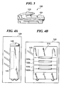
- FIG. 3 is a side view schematically showing the W/B scanner 100 in FIG. 2 .
- the B/W scanner 200 is provided with an original feeder 101 that feeds originals to be read.
- the original feeder 101 has a tray 102 on which originals to be fed are set.
- the B/W scanner 100 reads image information from originals with images drawn thereon by scanning them using a CCD line sensor, not shown, while irradiating them with light, and then converts the read image information into an electric signal as raster image data 30.
- the CPU 201 of the image controller 200 transmits this instruction to the scanner 100.
- the scanner 100 reads the images on the originals by feeding them sheet by sheet using the original feeder 101.
- FIGS. 4A and 4B are side views schematically showing examples of the W/B 20opm printer in FIG. 2 .
- the W/B 20opm printer 120 forms raster image data 40 (see FIG. 2 ) on printing sheets as images.
- the method of forming images includes an electrophotographic method using a photosensitive drum and a photosensitive belt (neither of them is shown), and an ink jet method of printing images directly on printing sheets by ejecting ink through a fine-jet nozzle array.
- a print operation is started in response to an instruction (raster image data 40) from the CPU 201.
- the B/W 20opm printer 120 has installed therein a plurality of sheet feeding stages in a manner allowing the user to select the size and direction of printing sheets, and a plurality of corresponding sheet feeding cassettes 122a, 122b, 122c, and 122d (see FIG. 4B ). Further, a sheet discharging tray 123 receives printing sheets that have been printed. If the B/W 20opm printer 120 has the finisher 124 installed therein as shown in FIG. 4A , printed printing sheets are conveyed to the finisher 124.
- the finisher 124 has a stapler unit 125 (postprocess unit) installed therein.
- the stapler unit 125 can staple each set of 50 or 100 printing sheets.
- the finisher 124 has an inserter unit 126 installed therein and having an insert tray (not shown).
- the inserter unit 126 can be used as one sheet feeding stage like the sheet feeding cassette 122a, 122b, 122c, or 122d. Since the inserter unit 126 is installed in the finisher 124, sheets (for example, cover sheets, interleaved sheets, or back cover sheets) fed from the inserter unit 126 via an insert tray thereof can be fed into the finisher 124 without passing through an image forming section or a fixing unit (neither of them is shown) in the B/W 20opm printer 120.
- sheets from the inserter unit cannot be printed (no images can be printed thereon) but can be inserted between printed printing sheets from the B/W 20opm printer 120 without being affected by heat generated by the printer 120.
- the finisher 124 can discharge (output) sheets printed in multiple colors so that the discharged printed sheets can be stapled bookbound in one bundle.
- the sheet is turned upside down in the W/B 20opm printer 120 after one side thereof has been printed. Subsequently, the other side, which has not been printed yet, is printed in response to an instruction (raster image data 40) from the CPU 201.
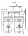
- FIG. 5 is a block diagram showing the construction of the device I/F 240 in FIG. 2 .
- an image bus I/F controller 241 installed in the device I/F 240 is connected to the image bus 208 to control a bus access sequence therefor. Further, the image bus I/F controller 241 controls devices in the device I/F 240, described below, and transmits control signals to the external scanner 100 and the B/W 20opm printer 120.
- a scan buffer 242 temporarily saves image data transmitted from the scanner 100, and outputs the saved image data to the image bus 208 in synchronization therewith.
- a serial-parallel and parallel-serial converting section 243 arranges the image data saved in the scan buffer 242, in an appropriate order, or decomposes the image data to convert it so as to have an appropriate data width for transfer to the image bus 208.
- a parallel-serial and serial-parallel converting section 244 decomposes image data transferred from the image bus 208 or arranges the image data in an appropriate order to convert it so as to have an appropriate data width for storage in the print buffer 245.
- the print buffer 245 temporarily saves the image data transferred from the image bus 208 and synchronously outputs the saved image data to the printer 120 in synchronization therewith.
- Image data transmitted from the scanner 100 is saved in the scan buffer 242 synchronously with a timing signal also transmitted from the scanner 100.
- the image bus 208 is a PIC bus
- 32 bits of image data of the stored data is transmitted to the serial-parallel and parallel-serial converting section 243 in a first-in first-out manner.
- the 32-bit data converted by the serial-parallel and parallel-serial converting section 243 is transferred to the image bus 208 via the image bus I/F controller 241.
- the image bus is of an IEEE 1394 type
- the image data in the buffer 242 is transmitted from the buffer 242 to the serial-parallel and parallel-serial converting section 243 in a first-in first-out manner.
- the serial image data converted by the serial-parallel and parallel-serial converting section 243 is transferred to the image bus 208 via the image bus I/F controller 241.
- the image bus 208 is a PCI bus
- 32-bit image data transmitted from the image bus 208 is received by the image bus I/F controller 241, which then transmits the data to the parallel-serial and serial-parallel converting section 244.
- the parallel-serial and serial-parallel converting section 244 decomposes the image data into an appropriate number of data bits to be input to the printer 120, and saves them in the print buffer 245.
- the image bus 208 is of an IEEE 1394
- serial image data transmitted from the image bus 208 is received by the image bus I/F controller 241, which then transmits the data to the parallel-serial and serial-parallel converting section 244.
- the parallel-serial and serial-parallel converting section 244 converts the image data into an appropriate number of data bits to be input to the printer 120, and saves them in the print buffer 245.
- the image data in the buffer 245 is transmitted to the printer 120 in a first-in first-out manner in synchronization with a timing signal transmitted from the printer 120.
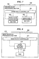
- FIG. 6 is a block diagram showing the construction of the scanner image processing section 250 in FIG. 2 .
- an image bus I/F controller 251 is connected to the image bus 208 to control a bus access sequence for the image bus 208.
- the image bus I/F controller 251 also controls the following devices constituting the scanner image processing section 250.
- a filter processing section 252 is a space filter that carries out convolution operations.
- An editing processing section 253 recognizes, for example, a closed area in input image data which is marked with a marker by a marker pen and carries out various image processes such as shading, screening, and negative-positive reversal on the image data in the closed area.
- a variable power processing section 254 carries out an interpolating operation on a raster image in a main scanning direction to magnify or reduce the image if the resolution of the image to be read is to be changed. Scaling (magnification/reduction) in a sub-scanning direction is carried out by changing the scanning speed of an image reading line sensor (not shown).
- a table processing section 255 carries out table conversions by converting read brightness data as image data into density data.
- a binarizing processing section 256 binarizes multi-valued gray scale image data by an error diffusion process or a screen process. The image data subjected to these processes is transferred again to the image bus 208 via the image bus I/F controller 251.
- FIG. 7 is a block diagram showing the construction of the printer image processing section in FIG. 2 .
- an image bus I/F controller 261 is connected to the image bus 208 to control a bus access sequence for the image bus 208.
- the image bus I/F controller 261 also controls devices constituting the printer image processing section 260. Among these devices, a resolution conversion processing section 262 converts image data received via the LAN 10 or the public telephone line 20 into data with an appropriate resolution for printing by the printer 120 (resolution conversion).
- a smoothing processing section 263 eliminates jaggies of the image data with its resolution converted. The term "jaggies" means oblique lines or curves which are jaggy rather than smooth.
- FIG. 8 is a block diagram showing the construction of the image rotation processing section 270 in FIG. 2 .
- an image bus I/F controller 271 is connected to the image bus 208 to control a bus sequence for the image bus 208.
- the image bus I/F controller 271 also sets modes for an image rotating section 272 and controls timing in which image data is transferred to the image rotating section 272. The details of processing carried out by the image processing section 272 will be described below.
- the CPU 201 gives an instruction for settings for image rotation control to the image bus I/F controller 271, then based on this instruction, the image bus I/F controller 271 makes settings required for image rotation for the image rotating section 272. Items to be set include, for example, image size, rotating direction, and angle. After the settings have been made, the CPU 201 again permits the image bus I/F controller 271 to transfer image data.
- the image bus I/F controller 271 starts transferring image data from the RAM 202 (see FIG. 2 ) or devices on the image bus 208.
- images to be rotated have a size of 32 x 32 bits, for example.
- 32 bits of image data are transferred at a time. Images handled in this case are assumed to have a binary format.
- the image data transferred by the discontinuous addressing is written to the RAM 273 so as to be rotated through a desired angle when read out. For example, for a counterclockwise rotation through 90°, initially transferred 32-bit image data is written in a Y direction (see FIG. 11 ). By reading out the image data in an X direction, the image is rotated.
- the image rotating section 272 reads out the image data from the RAM 273 using the above described readout method and then transfers the image to the image bus I/F controller 271.
- the image bus I/F controller 271 Upon receiving the rotated image data, the image bus I/F controller 271 transfers the data to the RAM 202 or devices on the image bus 208 by continuous addressing.
- FIG. 9 is a block diagram showing the construction of the image compression processing section 280 in FIG. 2 .
- an image bus I/F controller 281 is connected to the image bus 208 to control a bus access sequence therefor.
- the image bus I/F controller 281 also controls timing of data exchange between an input buffer 282 and an output buffer 285 and mode settings for an image compressing section 283.
- the image compressing section 283 has a RAM 284 connected thereto.
- the image compressing section 283 temporarily stores the received image data in the RAM 284.
- the reason why the image data is thus once stored in the RAM 284 is that data for several lines is required for image compression depending on the type of the image compressing process, so that image data for several lines must be stored before the compression of the first line is carried out.
- the compressed image data is transmitted to the output buffer 285.
- the output buffer 285 carries out handshaking between the image bus controller 281 and the image compressing section 283 to transfer the image data to the image bus I/F controller 281.
- the image bus I/F controller 281 transfers the transferred image data, which has been compressed (or decompressed), to the RAM 202 or devices on the image bus 208. The above sequence of steps are repeated until the CPU 201 stops issuing the processing request, for example, when a required number of pages have been processed or the image compressing section makes a stop request, for example, when an error occurs during compression or decompression.
- one or more images input from the scanner 100 or the network 209 are treated as a document or documents and can be stored in an image recording area called "a box".
- the image data and attribute data in the box are recorded in the HDD 204.
- FIG. 12 is a view illustrating a copy basic screen displayed in the operating section 210 in FIG. 2 .
- the copy basic screen 300 displays an applied mode button 301 that is depressed to allow the user to use various copy functions.
- FIG. 13 is a view illustrating an applied mode screen displayed in the operating section 210 in FIG. 2 .
- the applied mode screen 400 is displayed when the applied mode button 301 is depressed in the copy basic screen 300.
- a cover sheet/interleaved sheet button 401 is used to add (set) a cover sheet (separate sheet) to printing sheets on which images have been formed or insert (set) interleaved sheets (separate sheets) between the printing sheets.
- a banner 402 shown as "cover + back cover” is displayed when the cover sheet/interleaved sheet button 401 is depressed.
- the banner 402 displays some of the settings in a cover sheet/interleaved sheet selection screen 600, shown in FIG. 15 .
- the "cover + back cover” banner shows that it is set such that a cover sheet and a back cover sheet (separate sheets) are added to (set on) printing sheets on which images have been formed.
- FIG. 14 is a view illustrating a sheet feeding stage selection screen displayed in the operating section in FIG. 2 .
- the cover sheet/interleaved sheet sheet selection screen 500 in FIG. 14 is displayed when any of a sheet selection button 602, a back cover sheet selection button 603, and an interleaved sheet and chapter sheet selection button 604 is depressed.
- the user can select sheet feeding from the inserter unit 126 (see FIG. 4 ) via the screen in FIG. 14 .
- sheets such as cover sheets or back cover sheets are fed from the inserter unit 126, they are fed into the finisher without passing through the printer section. Accordingly, sheets with an image or images for the cover sheet and/or back cover sheet printed thereon are set in the inserter unit 126. In this case, it is assumed that the user depresses an inserter sheet feeding selection button 501 to select sheet feeding from the inserter unit 126.
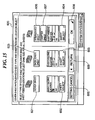
- FIG. 15 is a view showing an example of a cover sheet/interleaved sheet setting screen displayed in the operating section 210 in FIG. 2 .
- the cover sheet/interleaved sheet setting screen 600 is used to select the type of the cover sheet/interleaved sheet and sheet feeding sections, and is displayed when the cover sheet/interleaved sheet button 401 is depressed.
- a cover sheet button 601, back cover sheet button 605, interleaved sheet button 606, or chapter sheet button 607 is depressed, respectively.
- the user depresses these buttons the respective sheet feeding stages can be selected.
- a sheet feeding section selection screen is displayed, so that a cover sheet feeding stage can be selected as a desired one of a plurality of candidates including the sheet feeding section 122 of the printer section and the inserter unit 126.
- a sheet feeding section selection screen is displayed, so that a back cover sheet feeding stage can be selected as a desired one of a plurality of candidates including the sheet feeding section 122 of the printer section and the inserter unit 126.
- a sheet feeding section selection screen is displayed, so that an interleaved sheet feeding stage can be selected as a desired one of a plurality of candidates including the sheet feeding section 122 of the printer section and the inserter unit 126.
- an OK button 608 is depressed, the setting is completed.
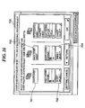
- FIG. 16 is a view showing another example of the cover sheet/interleaved sheet setting screen displayed in the operating section in FIG. 2 .
- cover sheet/interleaved sheet setting screen 700 a cover sheet button 701 and a back cover sheet button 703 have been depressed. Furthermore, the inserter unit 126 has been selected as a sheet feeding stage for both the cover sheet and back cover sheet by operating a cover sheet selection button 702 and a back cover sheet selection button 704.
- a cover sheet selection button 702 and a back cover sheet selection button 704. if the user makes the settings shown in the example in FIG. 15 , a single sheet from the inserter can be inserted into a bundle of sheets as an output result.
- a plurality of sheets for example, a cover sheet and a back cover sheet can be inserted into a bundle of sheets.
- any of these operations can be selected by the user.
- information set by the user via any of the setting screens in FIGS. 14 , 15 , and 16 is managed by the controller 200 for each job in a table form such as one shown in FIG. 21 , described later.
- the controller 200 controls the operation of various units such as the scanner 100, printer section 120, finisher 124, and inserter unit 126.
- FIG. 17 is a view illustrating a copy execution screen displayed in the operating section 210 in FIG. 2 , during copying.
- FIG. 18 is a view illustrating a jam screen displayed in the operating section 210 in FIG. 2 .
- the jam screen 900 is displayed when a jam occurs while a copy job is being executed.
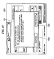
- FIG. 19 is a view illustrating a recovery screen displayed in the operating section 210 in FIG. 2 after the occurrence of a jam was notified to the user using the screen in FIG. 18 and then the user has detected that the jam had been eliminated.
- the recovery screen 100 can be displayed if a jam occurs while sheets are being fed from the inserter unit 126.
- a recovery instruction dialog 1001 then appears and displays an instruction to the user.
- a print restart button 1003 is depressed to restart the job during execution of which a jam has occurred. That is, the user manually instructs jam recovery to be executed.
- FIG. 20 is a flow chart showing a process executed when a jam occurs.
- a program that executes this process is stored in a memory such as the ROM 203 and is read out and executed by the image controller 200.
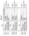
- FIG. 21 is a view illustrating a sheet feeding management table.
- the sheet feeding management table 1100 is provided for each job and has stored therein specification setting information concerning the sheet feeding stage being used in execution of the job.
- a text 1101, a cover sheet 1102, a back cover sheet 1103, and an interleaved sheet 1104 are associated with sections 1105, 1106, 1107, and 1108.
- N jobs that is, a job 1, a job 2, ⁇ ", a job N are registered as jobs to be output.
- Sheet feeding management information for the job 1, job 2, and job 3 is denoted by 1100-1, 1100-2, and 1100-3, respectively.
- the sheet feeding stage for the text 1101-1 is an automatic sheet feeding stage
- the sheet feeding stage for a cover sheet 1102-1 is the inserter unit
- the sheet feeding stage for a back cover sheet 1103-1 is a cassette 1 installed in the printer section.
- the sheet feeding stage for an interleaved sheet 1104-1 is represented as "none" because no interleaved sheet is used. That is, the job 1 causes the inserter to feed a single sheet.
- the sheet feeding stage for the text 1101-2 is the cassette 1 installed in the printer section (this means that images read from text originals using the scanner are printed on sheets from the cassette 1)
- the sheet feeding stage for a cover sheet 1102-2 is the inserter unit (this means that a sheet set in the inserter unit 126 is used as a cover sheet)
- the sheet feeding stage for a back cover sheet 1103-2 is also the inserter unit (this means that a sheet set in the inserter unit 126 is used as a back cover sheet)
- the sheet feeding stage for an interleaved sheet 1104-1 is a cassette 2 installed in the printer section (a sheet in the cassette 2 is used as an insert). That is, the job 2 causes the inserter to feed a plurality of sheets (that is, two sheets of the cover sheet and the back cover sheet).
- the sheet feeding stage for the text 1101-N is the cassette 1 installed in the printer section
- the sheet feeding stage for a cover sheet 1102-N is represented as "none” (no cover sheet is used)
- the sheet feeding stage for a back cover sheet 1103-N is also represented as “none” (no back cover sheet is used)
- the sheet feeding stage for an interleaved sheet 1104-N is also represented as “none” (no interleaved sheet is used). That is, the job N inhibits the inserter from feeding sheets (the inserter is not used).
- step S5001 the jam screen 900 is displayed in the operating screen 210 to notify the user of the jam and urge him to remove the jamming paper. Thereafter, the user waits until the jamming paper is removed to eliminate the jam (step S5002). Whether or not the jam has been eliminated (the jamming sheet has been removed) is determined based on results of detection of the presence of sheets executed by sensors installed in sheet conveyance passages inside the image forming apparatus main body and the finisher. Once the jam has been eliminated, the jam screen 900 disappears (step S5003), and the copy execution screen 800 is displayed in the operating screen 210.
- step S5004 the use of the sheet feeding stage in the job is determined (step S5004). That is, based on the sheet feeding management table 1100 shown in FIG. 21 , it is determined whether or not the job uses the inserter unit 126 as a sheet feeding stage. It is determined that the job uses the inserter unit 126 if the inserter unit 126 is designated in any of the sections 1105, 1106, 1107, and 1108 of the sheet feeding management table 1100. If the job uses the inserter unit 126, the process proceeds to the next step S5005. This will be explained by referring to the example in FIG. 21 .
- the jobs 1 and 2 in FIG. 21 correspond to the use of the inserter unit 126.
- step S5005 the process proceeds to the step S5005.
- the job N does not use the inserter unit 126. Consequently, if a jam occurs during execution of the job N, the process proceeds to a step S5008.
- step S5005 it is determined whether or not the job requires a plurality of sheets to be fed from the inserter unit 126 for a bundle for one copy. If a plurality of sheets are to be fed from the inserter unit 126, that is, for example, if the inserter unit 126 is designated in two or more of the sections 1105, 1106, 1107, and 1108 as in the example of settings shown in FIG. 16 , then the recovery instruction dialog 1101, shown in FIG. 19 , is displayed to urge the user to check sheets from the inserter again (step S5006). This will be explained by referring to the example in FIG. 21 . In the job 1 in FIG. 21 , the inserter unit 126 feeds only one sheet.
- the inserter unit 126 need not feed a plurality of sheets for a bundle for one copy. Consequently, if a jam occurs during the job 1, the process proceeds to the step S5008.
- the inserter unit 126 feeds two sheets. That is, the job requires the inserter unit 126 to feed a plurality of sheets for a bundle for one copy. Consequently, if a jam occurs during execution of the job 2, the process proceeds to the step S5006.
- step S5007 the system waits for an instruction from the user (step S5007).
- the print restart button 1003 FIG. 19
- a jam recovery process is executed to restart the interrupted job, and the entire process is then completed (step S5008).
- the recovery operation in the step S5008 for example, if a bundle of originals comprised of five pages are printed starting with a first page and if the sheet on which the third page of the originals is being printed has jammed, then the process is restarted from the third page of the originals.
- At which page the sheet has jammed is determined based on setting information input through the operating section by the user, information from a counter installed in the sheet discharging section of the image forming apparatus to count the number of discharged sheets (count the number of sheets for which outputs have been completed), or the like.
- the input order of images is different from the output order thereof in which the images are actually printed on sheets (the order of the pages is changed during printing). Accordingly, if a jam occurs while such an image forming operation is being carried out, the recovery operation is carried out by restarting the process, for example, from the first page.
- the process is restarted from the beginning of one of the copies.
- the recovery operation restarts the process, for example, from an operation of causing the inserter unit 126 to feed sheets. Whether or not any sheet from the inserter unit 126 has jammed is determined based on setting information input by the user via the operation screens in FIGS. 14 , 15 , 16 , information from a sensor installed on a path along which sheets from the inserter unit 126 are conveyed, or the like. Any of these processes is executed in the step S5008 as a recovery process.
- step S5004 If the result of the determination in the step S5004 shows that the job does not use the inserter unit 126, the process proceeds to the step S5008 by skipping the above described steps S5005 to S5007, and is then completed. If the job does not use the inserter unit 126, the inserter unit 126 is not designated in any of the sections 1105, 1106, 1107, and 1108 of the sheet feeding management table 1100. For example, in the example in FIG. 21 , this case corresponds to the job N.
- step S5005 If the result of the determination in the step S5005 shows that the inserter unit 126 does not feed a plurality of sheets, that is, for example, if the inserter unit 126 is designated in only one of the sections 1105, 1106, 1107, and 1108 as in the example of settings shown in FIG. 15 , then the process proceeds to the step S5008 and is thus completed. For example, in the example in FIG. 21 , this case corresponds to the job 2.
- the jam screen 900 is displayed in the operating screen 210 to notify the user that a jam has occurred and urge him to remove the jamming sheet (step S5001).
- the recovery instruction dialog 1001 is displayed in order to urge the user to check sheets from the inserter (step S5006).
- the interrupted job is restarted, and then the process is completed (step S5008).
- the recovery operation when the recovery operation is to be performed on the job for which the image forming operation has been interrupted due to a sheet jam or the like, if the job for which the process has been interrupted uses the inserter unit 126 and requires the inserter unit 126 to feed two or more sheets, then the display as shown in FIG. 19 is provided in the operating section, to notify the user that the inserter unit 126 should be checked. Then, control is provided to resume the recovery operation in response to the depression by the user of the restart button 1003 in the screen 1001 in FIG. 19 . That is, control is provided such that the recovery operation is inhibited from being automatically executed and is instead started in response to an instruction from the user (the mode in which the recovery operation is started in response to an instruction from the user).
- the notification as shown in FIG. 19 is not given to the user, and control is provided to automatically execute the recovery process. That is, control is provided such that the notification process for the user is inhibited and the recovery operation is automatically started (the mode in which the recovery operation is started without any instruction from the user).
- control is switched depending on whether the inserter unit 126 feeds one sheet or a plurality of sheets. This takes into consideration various conditions such as those described below. For example, if a plurality of copies are printed and the inserter unit 126 feeds two sheets, that is, a cover sheet and a back cover sheet while a bundle of sheets for one copy are being printed, a number of cover sheets and back cover sheets corresponding to the plurality of copies are alternately set into the inserter.
- the present embodiment provides such control that if the interrupted job requires the inserter unit 126 to feed a plurality of sheets for a bundle for one copy, the recovery operation is not automatically carried out but carried out in response to an instruction from the user. On the other hand, if the job requires the inserter unit 126 to feed only one sheet for a bundle for one copy, the recovery operation is started without any instruction from the user because the above described inconvenience does not occur.
- the recovery method is switched between the case where the inserter unit 126 feeds one sheet for a bundle for one copy and the case where the inserter unit 126 feeds a plurality of sheets for a bundle for one copy.
- the present invention is applicable to the following arrangements in order to simplify the process of determining whether the interrupted job requires the inserter unit 126 to feed one sheet or a plurality of sheets (the processing in the step S5005), or other processes:
- control may be provided such that whatever job is interrupted, the user is notified of the interruption without the recovery process being automatically executed. But, in this case as well, the contents of the notification varies depending on the type of the interrupted job. For example, if the interrupted job uses the inserter unit 126 (in the example in FIG. 21 , the job 1 or job 2), a display as shown in FIG. 22A is provided. On the other hand, control is provided such that if the job does not the inserter unit 126 (in the example in FIG. 21 , the job N), a display as shown in FIG. 22B is provided.
- a display as shown in FIG. 22 is provided.
- control may be provided such that if the job does not use the inserter unit 126 or requires the inserter unit 126 to feed only one sheet (in the example in FIG. 21 , the job 1 or job N), a display as shown in FIG. 22B is provided.
- the recovery operation is carried out when a sheet jam occurs.
- the present invention is applicable to a recovery operation carried out when the job is interrupted due to an original jam in the original feeder or a staple jam in a staple unit (not shown).
- the job is interrupted based on information from various sensors installed inside the apparatus, and then control is provided such that the above described recovery operation is carried out when it is ascertained that the user has eliminated the cause of the job interruption.
- the present invention is also applicable to processing of data input from an external apparatus via the LAN 10 or WAN 20 in FIG. 2 .
- a personal computer to be used is constructed so as to display the various operation screens shown in FIGS. 13 to 19 and 22 so that the user is instructed to make settings for the inserter unit 126 via the screens in FIGS. 14 to 16 and other figures on the computer.
- the resulting setting information is then transmitted to the printer together with image data, and the printer then carries out a printing process.
- the printer transmits corresponding information to the personal computer to cause it to provide the display in FIG. 18 .
- the display in FIG. 19 or 22 is provided on the personal computer depending on the type of interrupted job, as in the above described embodiments.
- control is provided such that the printer restarts the process in response to depression of the button 1003.
- the process is executed by the image controller, but it may be executed by a control section, not shown, of the image forming apparatus.
- an arbitrary storage medium having the above processing method stored therein may supply a control section of an image controller or an image forming apparatus with a program that executes the processing method so that either a CPU of the image controller or an MPU thereof, not shown, can execute this program.
- the above storage medium may supply the above program to the control section of the image forming apparatus so that either a CPU or MPU, not shown, of the image forming apparatus can execute the program.
- the storage medium may be selected from, for example, a RAM, NV-RAM, a floppy (registered trade mark) disk, hard disk, optical disk, magneto-optical disk, CD-ROM, MO, CD-RW, DVD (DVD-ROM, DVD-R), magnetic tape, non-volatile memory, and ROM.
- a circuit, not shown, having similar operations to the CPU or MPU may implement the above described embodiment.
- a circuit, not shown, having similar operations to the CPU or MPU may implement the above described embodiment.
- the program supplied by the storage medium may be written into a memory, not shown, provided in an expanded board, not shown, inserted in an image controller, or an expanded unit, not shown, connected to an image control apparatus, and a CPU, not shown, or the like provided in the expanded board or expanded unit may then perform a part or all of the program.
- the program supplied by the storage medium may be written into a memory, not shown, provided in an expanded board, not shown, inserted in an image forming apparatus, or an expanded unit, not shown, connected to an image forming apparatus, and a CPU, not shown, or the like provided in the expanded board or expanded unit may then perform a part or all of the program.
Description
- This invention relates to an image forming system, a control method therefor, and a storage medium storing a program for executing the control method.
- In conventional image forming systems such as copiers and printers, an inserter feeds only cover sheets.
- If the inserter is adapted to feed not only cover sheets but also interleaved sheets and back cover sheets, this single inserter (sheet feeding stage) will have a plurality of different types of sheets (cover sheets, interleaved sheets, and back cover sheets) placed thereon. Thus, when a job that has been interrupted due to a jam or the like is recovered and then a sheet feeding operation is resumed, there is a possibility that the next fed sheet is not fed correctly.
- It is an object of the present invention to provide an image forming system, and a control method therefor, as well as a storage medium storing a program for executing this control method.
- To attain the above object, a first aspect of the present invention provides an image forming system as defined in
claims 1 to 7. To attain the above object, a second aspect of the present invention provides a method of controlling an image forming system as defined inclaims 8 to 12. To attain the above object, a third aspect of the present invention further provides a computer-readable storage medium storing a computer-executable program as defined inclaims 13. - An advantage of the first aspect of the present invention is that if a jam occurs, information related to the jam that has occurred may be displayed. This display is changed depending on the number of type of sheets detected and whether an inserter is used. Therefore, the user can take necessary measures, such as inhibiting or allowing a recovery operation, depending upon the number of type of separate sheets and whether an inserter is used. As a result, sheets to be fed can be properly fed. As a further feature of the present invention, whether or not a recovery operation is to be carried out for an interrupted job is determined based on whether or not the interrupted job uses an inserter. As a result, this can allow an interrupted job to be properly processed.
- The above and other objects, features, and advantages of the present invention will be more apparent from the following detailed description taken in conjunction with the accompanying drawings.
-
-
FIG. 1 is a block diagram showing the construction of an image forming system according to an embodiment of the present invention; -
FIG. 2 is a block diagram showing the construction of animage forming apparatus 200 appearing inFIG. 1 ; -
FIG. 3 is a side view schematically showing a B/W scanner 100 appearing inFIG. 1 ; -
FIG. 4A is a side view schematically showing a low-speed black-and-white printer 120 appearing inFIG. 2 ; -
FIG. 4B is a side view schematically showing another example of low-speed black-and-white printer 120 appearing inFIG. 2 ; -
FIG. 5 is a block diagram showing the construction of a device interface (I/F) 240 appearing inFIG. 2 ; -
FIG. 6 is a block diagram showing the construction of a scanner image processing section appearing inFIG. 2 ; -
FIG. 7 is a block diagram showing the construction of a printerimage processing section 260 appearing inFIG. 2 ; -
FIG. 8 is a block diagram showing the construction of an imagerotation processing section 270 appearing inFIG. 2 ; -
FIG. 9 is a block diagram showing the construction of an image compression processing section appearing inFIG. 2 ; -
FIGS. 10A and 10B is a view useful in explaining image rotation; -
FIG. 11 is a view showing a manner of rotating an image; -
FIG. 12 is a view illustrating a copy basic screen displayed in anoperating section 210 appearing inFIG. 2 ; -
FIG. 13 is a view illustrating an applied mode screen displayed in theoperating section 210 inFIG. 2 ; -
FIG. 14 is a view illustrating a feeding stage selecting screen displayed in theoperating section 210 inFIG. 2 ; -
FIG. 15 is a view showing an example of a cover sheet/interleaved sheet setting screen displayed in theoperating section 210 inFIG. 2 ; -
FIG. 16 is a view showing another example of the cover sheet/interleaved sheet setting screen displayed in theoperating section 210 inFIG. 2 ; -
FIG. 17 is a view illustrating a copy executing screen displayed in theoperating section 210 inFIG. 2 during copying; -
FIG. 18 is a view illustrating a jam screen displayed in theoperating screen 210 inFIG. 2 ; -
FIG. 19 is a view illustrating a recovery screen displayed in theoperating screen 210 inFIG. 2 ; -
FIG. 20 is a flow chart showing a process executed when a jam occurs; -
FIG. 21 is a view illustrating a sheet-feeding managing table; and -
FIGS. 22A and22B are views showing displays provided when a job is interrupted, depending on the type of the interrupted job. - The present invention will now be described below with reference to the drawings showing a preferred embodiment thereof.
-
FIG. 1 is a block diagram showing an image forming system according to an embodiment of the present invention. - In
FIG. 1 , theimage forming system 1 is comprised of a B/W (black-and-white)scanner 100 that can read black-and-white originals and acolor scanner 110 that can read color originals, both scanners being provided as image input apparatuses, a low-speed black-and-white printer (B/W 20opm printer) 120, a medium-speed black-and-white printer (B/W 40opm printer) 130, and a high-speed black-and-white printer (B/W 60opm printer) 140, and a color printer (color 10ppm printer) 150, all provided as image output apparatuses (image forming apparatuses), anoffline finisher 160 that can postprocess printing sheets off-line, aserver computer 170 having a mass storage, and apersonal computer 180 for a personal user, all these components being connected to a LAN (Local Area Network) 10 such as an Ethernet. In thisimage forming system 1, the B/W scanner 100 and the B/W 20opm printer 120 are connected together via alocal video bus 11 dedicated to black-and-white image formation. Further, thecolor scanner 110 and thecolor printer 150 are connected together via alocal video bus 12 dedicated to color image formation. In this embodiment, the B/W scanner 100, animage controller 200, the B/W printer 120 (or 140), and an online finisher 124 (or 134) may be integrated together or separated from one another so as to function as an image forming apparatus such as a black-and-white copier. Likewise, thecolor scanner 110, theimage controller 200, thecolor printer 150, and anonline finisher 154 may be integrated together or separated from one another so as to function as an image forming apparatus such as a color copier. - The B/
W scanner 100 and thecolor scanner 110 each have theimage controller 200 connected thereto via an exclusive local bus, not shown, for controlling image reading and image transfer. - The B/
W 20opm printer 120, B/W 40opm printer 130, B/W 60opm printer 140, andcolor printer 150 have respectiveonline finishers -
FIG. 2 is a block diagram showing the construction of theimage controller 200 inFIG. 1 . - In
FIG. 2 , the image controller 200 inputs and outputs image and device information. Theimage controller 200 is connected to the B/W scanner 100 and B/W 20opm printer 120 to carry out overall control of various units such as thescanner 100 and theprinter 120 including thefinisher 124 and execute various processes including one shown in a flow chart ofFIG. 20 , described later. Theimage controller 200 is also connected to theLAN 10 and a public telephone line (WAN) 20. Thus, theimage controller 200 can also process data (including image and device information) from external apparatuses, which are input via theLAN 10, theWAN 20, or the like. - A
CPU 201 is a controller that controls the entire system. ARAM 202 is a system work memory for operation of theCPU 201 and which is also used as an image memory temporarily storing image data. AROM 203 is a boot ROM that stores a system boot program (including programs that execute various processes including the one shown in the flow chart ofFIG. 20 , described later). An HDD (Hard Disk Drive) 204 stores system software and image data. Further, theHDD 204 saves information on nodes connected to the network (LAN 10), such as image output speeds and installation positions of the nodes. - An operating section interface (I/F) 206 is an interface section connected to an operating section (user interface) 210 to output image data thereto. Based on the image data, images are displayed on the
operating section 210. Information input via theoperating section 210 by a user of this system is transmitted to theCPU 201 via theoperating section interface 206. - A
network 209 is connected to theLAN 10 to input and output information. Amodem 220 is connected to thepublic telephone line 20 to input and output information via theline 20. These devices are arranged on asystem bus 207. - An image bus interface (I/F) 205 is a bus bridge that connects an
image bus 208 which transfer image data at high speed and thesystem bus 207 together, to convert data structures. Theimage bus 208 is comprised of a high-speed bus such as a PIC bus. - Various devices, described below, are arranged on the
image bus 208. A raster image processor (RIP) 230 expands a PDL code into a bit map image. A device interface (I/F) 240 connects theimage controller 200, B/W scanner 100, and B/W 20opm printer 120 together to carry out synchronous/asynchronous conversion of image data. A scannerimage processing section 250 corrects, processes, and edits input image data. A printerimage processing section 260 corrects the printer or carries out resolution conversion or other processes so as to provide good print output image data. Animage rotating section 270 rotates image data. Animage compressing section 280 carries out compression of multi-valued image data into JPEG data and decompression thereof and compression of binary data into JBIG, MMR, or MH data and decompression thereof. -
FIG. 3 is a side view schematically showing the W/B scanner 100 inFIG. 2 . - The B/
W scanner 200 is provided with anoriginal feeder 101 that feeds originals to be read. Theoriginal feeder 101 has atray 102 on which originals to be fed are set. The B/W scanner 100 reads image information from originals with images drawn thereon by scanning them using a CCD line sensor, not shown, while irradiating them with light, and then converts the read image information into an electric signal asraster image data 30. When the user operates the operating section 210 (seeFIG. 2 ) to give an instruction for reading the originals, theCPU 201 of theimage controller 200 transmits this instruction to thescanner 100. Upon receiving the instruction, thescanner 100 reads the images on the originals by feeding them sheet by sheet using theoriginal feeder 101. -
FIGS. 4A and 4B are side views schematically showing examples of the W/B 20opm printer inFIG. 2 . - The W/
B 20opm printer 120 forms raster image data 40 (seeFIG. 2 ) on printing sheets as images. The method of forming images includes an electrophotographic method using a photosensitive drum and a photosensitive belt (neither of them is shown), and an ink jet method of printing images directly on printing sheets by ejecting ink through a fine-jet nozzle array. - A print operation is started in response to an instruction (raster image data 40) from the
CPU 201. The B/W 20opm printer 120 has installed therein a plurality of sheet feeding stages in a manner allowing the user to select the size and direction of printing sheets, and a plurality of correspondingsheet feeding cassettes FIG. 4B ). Further, asheet discharging tray 123 receives printing sheets that have been printed. If the B/W 20opm printer 120 has thefinisher 124 installed therein as shown inFIG. 4A , printed printing sheets are conveyed to thefinisher 124. Thefinisher 124 has a stapler unit 125 (postprocess unit) installed therein. Thestapler unit 125 can staple each set of 50 or 100 printing sheets. - The
finisher 124 has aninserter unit 126 installed therein and having an insert tray (not shown). Theinserter unit 126 can be used as one sheet feeding stage like thesheet feeding cassette inserter unit 126 is installed in thefinisher 124, sheets (for example, cover sheets, interleaved sheets, or back cover sheets) fed from theinserter unit 126 via an insert tray thereof can be fed into thefinisher 124 without passing through an image forming section or a fixing unit (neither of them is shown) in the B/W 20opm printer 120. Accordingly, sheets from the inserter unit cannot be printed (no images can be printed thereon) but can be inserted between printed printing sheets from the B/W 20opm printer 120 without being affected by heat generated by theprinter 120. Further, by setting originals printed in colors, on theinserter unit 126, thefinisher 124 can discharge (output) sheets printed in multiple colors so that the discharged printed sheets can be stapled bookbound in one bundle. - To print both sides of the printing sheet, the sheet is turned upside down in the W/
B 20opm printer 120 after one side thereof has been printed. Subsequently, the other side, which has not been printed yet, is printed in response to an instruction (raster image data 40) from theCPU 201. - Now, the device I/
F 240 will be described. -
FIG. 5 is a block diagram showing the construction of the device I/F 240 inFIG. 2 . - In
FIG. 5 , an image bus I/F controller 241 installed in the device I/F 240 is connected to theimage bus 208 to control a bus access sequence therefor. Further, the image bus I/F controller 241 controls devices in the device I/F 240, described below, and transmits control signals to theexternal scanner 100 and the B/W 20opm printer 120. - A
scan buffer 242 temporarily saves image data transmitted from thescanner 100, and outputs the saved image data to theimage bus 208 in synchronization therewith. A serial-parallel and parallel-serial converting section 243 arranges the image data saved in thescan buffer 242, in an appropriate order, or decomposes the image data to convert it so as to have an appropriate data width for transfer to theimage bus 208. A parallel-serial and serial-parallel convertingsection 244 decomposes image data transferred from theimage bus 208 or arranges the image data in an appropriate order to convert it so as to have an appropriate data width for storage in theprint buffer 245. Theprint buffer 245 temporarily saves the image data transferred from theimage bus 208 and synchronously outputs the saved image data to theprinter 120 in synchronization therewith. - Here, the details of image scan processing will be described. Image data transmitted from the
scanner 100 is saved in thescan buffer 242 synchronously with a timing signal also transmitted from thescanner 100. - If the
image bus 208 is a PIC bus, when 32 bits or more of image data is fed to and stored in thebuffer serial converting section 243 in a first-in first-out manner. The 32-bit data converted by the serial-parallel and parallel-serial converting section 243 is transferred to theimage bus 208 via the image bus I/F controller 241. On the other hand, if the image bus is of an IEEE 1394 type, the image data in thebuffer 242 is transmitted from thebuffer 242 to the serial-parallel and parallel-serial converting section 243 in a first-in first-out manner. The serial image data converted by the serial-parallel and parallel-serial converting section 243 is transferred to theimage bus 208 via the image bus I/F controller 241. - Now, the details of processing for image printing will be described. If the
image bus 208 is a PCI bus, 32-bit image data transmitted from theimage bus 208 is received by the image bus I/F controller 241, which then transmits the data to the parallel-serial and serial-parallel convertingsection 244. The parallel-serial and serial-parallel convertingsection 244 decomposes the image data into an appropriate number of data bits to be input to theprinter 120, and saves them in theprint buffer 245. On the other hand, if theimage bus 208 is of an IEEE 1394, serial image data transmitted from theimage bus 208 is received by the image bus I/F controller 241, which then transmits the data to the parallel-serial and serial-parallel convertingsection 244. The parallel-serial and serial-parallel convertingsection 244 converts the image data into an appropriate number of data bits to be input to theprinter 120, and saves them in theprint buffer 245. The image data in thebuffer 245 is transmitted to theprinter 120 in a first-in first-out manner in synchronization with a timing signal transmitted from theprinter 120. - Next, the scanner
image processing section 250 will be described. -
FIG. 6 is a block diagram showing the construction of the scannerimage processing section 250 inFIG. 2 . - In
FIG. 6 , an image bus I/F controller 251 is connected to theimage bus 208 to control a bus access sequence for theimage bus 208. The image bus I/F controller 251 also controls the following devices constituting the scannerimage processing section 250. - A
filter processing section 252 is a space filter that carries out convolution operations. Anediting processing section 253 recognizes, for example, a closed area in input image data which is marked with a marker by a marker pen and carries out various image processes such as shading, screening, and negative-positive reversal on the image data in the closed area. A variablepower processing section 254 carries out an interpolating operation on a raster image in a main scanning direction to magnify or reduce the image if the resolution of the image to be read is to be changed. Scaling (magnification/reduction) in a sub-scanning direction is carried out by changing the scanning speed of an image reading line sensor (not shown). Atable processing section 255 carries out table conversions by converting read brightness data as image data into density data. Abinarizing processing section 256 binarizes multi-valued gray scale image data by an error diffusion process or a screen process. The image data subjected to these processes is transferred again to theimage bus 208 via the image bus I/F controller 251. - Now, the printer
image processing section 260 will be described. -
FIG. 7 is a block diagram showing the construction of the printer image processing section inFIG. 2 . - In
FIG. 7 , an image bus I/F controller 261 is connected to theimage bus 208 to control a bus access sequence for theimage bus 208. The image bus I/F controller 261 also controls devices constituting the printerimage processing section 260. Among these devices, a resolutionconversion processing section 262 converts image data received via theLAN 10 or thepublic telephone line 20 into data with an appropriate resolution for printing by the printer 120 (resolution conversion). A smoothingprocessing section 263 eliminates jaggies of the image data with its resolution converted. The term "jaggies" means oblique lines or curves which are jaggy rather than smooth. - Next, the image
rotation processing section 270 will be described. -
FIG. 8 is a block diagram showing the construction of the imagerotation processing section 270 inFIG. 2 . - In
FIG. 8 , an image bus I/F controller 271 is connected to theimage bus 208 to control a bus sequence for theimage bus 208. The image bus I/F controller 271 also sets modes for animage rotating section 272 and controls timing in which image data is transferred to theimage rotating section 272. The details of processing carried out by theimage processing section 272 will be described below. - When the CPU 201 (see
FIG. 2 ) gives an instruction for settings for image rotation control to the image bus I/F controller 271, then based on this instruction, the image bus I/F controller 271 makes settings required for image rotation for theimage rotating section 272. Items to be set include, for example, image size, rotating direction, and angle. After the settings have been made, theCPU 201 again permits the image bus I/F controller 271 to transfer image data. - In accordance with this permission, the image bus I/
F controller 271 starts transferring image data from the RAM 202 (seeFIG. 2 ) or devices on theimage bus 208. In this case, images to be rotated have a size of 32 x 32 bits, for example. Further, when image data is transferred to theimage bus - To obtain an image of size 32 x 32 bits as mentioned above, the above-mentioned number of bits of data transfer must be carried out 32 times, and image data from discontinuous addresses must be transferred (see
FIGS. 10A and 10B ). - The image data transferred by the discontinuous addressing is written to the
RAM 273 so as to be rotated through a desired angle when read out. For example, for a counterclockwise rotation through 90°, initially transferred 32-bit image data is written in a Y direction (seeFIG. 11 ). By reading out the image data in an X direction, the image is rotated. - Once the 32 x 32 bit image data has been rotated (written to the RAM 273), the
image rotating section 272 reads out the image data from theRAM 273 using the above described readout method and then transfers the image to the image bus I/F controller 271. - Upon receiving the rotated image data, the image bus I/
F controller 271 transfers the data to theRAM 202 or devices on theimage bus 208 by continuous addressing. - The above sequence of steps are repeated until the
CPU 201 stops making a processing request when, for example, a required number of pages have been processed. - Now, the image
compression processing section 280 will be described. -
FIG. 9 is a block diagram showing the construction of the imagecompression processing section 280 inFIG. 2 . - In
FIG. 9 , an image bus I/F controller 281 is connected to theimage bus 208 to control a bus access sequence therefor. The image bus I/F controller 281 also controls timing of data exchange between aninput buffer 282 and anoutput buffer 285 and mode settings for animage compressing section 283. Theimage compressing section 283 has aRAM 284 connected thereto. The details of processing carried out by the imagecompression processing section 280 thus constructed are as follows: - The
CPU 201 gives an instruction for settings for image compression control to the image bus I/F controller 281. Then, based on the instruction, the image bus I/F controller 281 makes settings required for image compression for theimage compressing section 283. The items to be set include, for example, MMR compression and JBIG decompression. After the settings have been made, theCPU 201 again permits the image bus I/F controller 281 to transfer image data. In accordance with this permission, the image bus I/F controller 281 starts transferring image data from theRAM 202 or devices on theimage bus 208. The received image data is temporarily stored in theinput buffer 282, and the image is transferred at a fixed speed in accordance with an image data request from theimage compressing section 283. On this occasion, theinput buffer 282 determines whether image data can be transferred between the image bus I/F controller 281 and theimage compressing section 283. If it is impossible to load image data from theimage bus 208 and to write images to theimage compressing section 283, control is provided such that no data is transferred. Such control will be hereinafter referred to as handshaking. - The
image compressing section 283 temporarily stores the received image data in theRAM 284. The reason why the image data is thus once stored in theRAM 284 is that data for several lines is required for image compression depending on the type of the image compressing process, so that image data for several lines must be stored before the compression of the first line is carried out. - Immediately upon completion of the image compression, the compressed image data is transmitted to the
output buffer 285. Theoutput buffer 285 carries out handshaking between theimage bus controller 281 and theimage compressing section 283 to transfer the image data to the image bus I/F controller 281. - The image bus I/
F controller 281 transfers the transferred image data, which has been compressed (or decompressed), to theRAM 202 or devices on theimage bus 208. The above sequence of steps are repeated until theCPU 201 stops issuing the processing request, for example, when a required number of pages have been processed or the image compressing section makes a stop request, for example, when an error occurs during compression or decompression. - In the image forming system constructed as described above, one or more images input from the
scanner 100 or thenetwork 209 are treated as a document or documents and can be stored in an image recording area called "a box". The image data and attribute data in the box are recorded in theHDD 204. -
FIG. 12 is a view illustrating a copy basic screen displayed in theoperating section 210 inFIG. 2 . - The copy
basic screen 300 displays an appliedmode button 301 that is depressed to allow the user to use various copy functions. -
FIG. 13 is a view illustrating an applied mode screen displayed in theoperating section 210 inFIG. 2 . - The applied
mode screen 400 is displayed when the appliedmode button 301 is depressed in the copybasic screen 300. A cover sheet/interleavedsheet button 401 is used to add (set) a cover sheet (separate sheet) to printing sheets on which images have been formed or insert (set) interleaved sheets (separate sheets) between the printing sheets. Abanner 402 shown as "cover + back cover" is displayed when the cover sheet/interleavedsheet button 401 is depressed. Thebanner 402 displays some of the settings in a cover sheet/interleavedsheet selection screen 600, shown inFIG. 15 . In this case, the "cover + back cover" banner shows that it is set such that a cover sheet and a back cover sheet (separate sheets) are added to (set on) printing sheets on which images have been formed. -
FIG. 14 is a view illustrating a sheet feeding stage selection screen displayed in the operating section inFIG. 2 . - The cover sheet/interleaved sheet
sheet selection screen 500 inFIG. 14 is displayed when any of asheet selection button 602, a back coversheet selection button 603, and an interleaved sheet and chaptersheet selection button 604 is depressed. In addition to sheet feeding from the sheet feeding section 122 of the printer, the user can select sheet feeding from the inserter unit 126 (seeFIG. 4 ) via the screen inFIG. 14 . For example, if sheets such as cover sheets or back cover sheets are fed from theinserter unit 126, they are fed into the finisher without passing through the printer section. Accordingly, sheets with an image or images for the cover sheet and/or back cover sheet printed thereon are set in theinserter unit 126. In this case, it is assumed that the user depresses an inserter sheetfeeding selection button 501 to select sheet feeding from theinserter unit 126. -
FIG. 15 is a view showing an example of a cover sheet/interleaved sheet setting screen displayed in theoperating section 210 inFIG. 2 . - The cover sheet/interleaved
sheet setting screen 600 is used to select the type of the cover sheet/interleaved sheet and sheet feeding sections, and is displayed when the cover sheet/interleavedsheet button 401 is depressed. When the cover sheet, back cover sheet, interleaved sheet, or chapter sheet (separate sheet) is used, acover sheet button 601, backcover sheet button 605, interleavedsheet button 606, orchapter sheet button 607 is depressed, respectively. When the user depresses these buttons, the respective sheet feeding stages can be selected. When thecover sheet button 601 and then a coversheet selection button 602 are depressed, a sheet feeding section selection screen, not shown, is displayed, so that a cover sheet feeding stage can be selected as a desired one of a plurality of candidates including the sheet feeding section 122 of the printer section and theinserter unit 126. When the backcover sheet button 605 and then a back coversheet selection button 603 are depressed, a sheet feeding section selection screen, not shown, is displayed, so that a back cover sheet feeding stage can be selected as a desired one of a plurality of candidates including the sheet feeding section 122 of the printer section and theinserter unit 126. When the interleavedsheet button 606 and then an interleaved sheet and chapter sheetsheet selection button 604 are depressed, a sheet feeding section selection screen, not shown, is displayed, so that an interleaved sheet feeding stage can be selected as a desired one of a plurality of candidates including the sheet feeding section 122 of the printer section and theinserter unit 126. After these selections, when anOK button 608 is depressed, the setting is completed. -
FIG. 16 is a view showing another example of the cover sheet/interleaved sheet setting screen displayed in the operating section inFIG. 2 . - In the cover sheet/interleaved
sheet setting screen 700, acover sheet button 701 and a backcover sheet button 703 have been depressed. Furthermore, theinserter unit 126 has been selected as a sheet feeding stage for both the cover sheet and back cover sheet by operating a coversheet selection button 702 and a back coversheet selection button 704. Thus, in this embodiment, if the user makes the settings shown in the example inFIG. 15 , a single sheet from the inserter can be inserted into a bundle of sheets as an output result. On the other hand, if the user makes the settings shown in the example inFIG. 16 , then a plurality of sheets, for example, a cover sheet and a back cover sheet can be inserted into a bundle of sheets. Any of these operations can be selected by the user. In this respect, information set by the user via any of the setting screens inFIGS. 14 ,15 , and16 is managed by thecontroller 200 for each job in a table form such as one shown inFIG. 21 , described later. Based on the set information, thecontroller 200 controls the operation of various units such as thescanner 100,printer section 120,finisher 124, andinserter unit 126. -
FIG. 17 is a view illustrating a copy execution screen displayed in theoperating section 210 inFIG. 2 , during copying. - When various output job settings are completed via the setting screens such as in
FIGS. 14 to 16 and then the user depresses a start key, not shown, in theoperating section 210, a copy job is started to start loading originals, and thecopy execution screen 800 is displayed. The screen displayed on thecopy execution screen 800 is acopy dialog 801 that shows how the copy job is going. -
FIG. 18 is a view illustrating a jam screen displayed in theoperating section 210 inFIG. 2 . - The
jam screen 900 is displayed when a jam occurs while a copy job is being executed. -
FIG. 19 is a view illustrating a recovery screen displayed in theoperating section 210 inFIG. 2 after the occurrence of a jam was notified to the user using the screen inFIG. 18 and then the user has detected that the jam had been eliminated. - The
recovery screen 100 can be displayed if a jam occurs while sheets are being fed from theinserter unit 126. Arecovery instruction dialog 1001 then appears and displays an instruction to the user. Aprint restart button 1003 is depressed to restart the job during execution of which a jam has occurred. That is, the user manually instructs jam recovery to be executed. - Next, the details of processing executed when a jam occurs will be described with reference to
FIGS. 20 and21 . -
FIG. 20 is a flow chart showing a process executed when a jam occurs. A program that executes this process is stored in a memory such as theROM 203 and is read out and executed by theimage controller 200. -
FIG. 21 is a view illustrating a sheet feeding management table. - The sheet feeding management table 1100 is provided for each job and has stored therein specification setting information concerning the sheet feeding stage being used in execution of the job. In this example, a
text 1101, acover sheet 1102, aback cover sheet 1103, and an interleavedsheet 1104 are associated withsections job 1, ajob 2, ´", a job N are registered as jobs to be output. Sheet feeding management information for thejob 1,job 2, andjob 3 is denoted by 1100-1, 1100-2, and 1100-3, respectively. - As regards the sheet feeding information for the
job 1, the sheet feeding stage for the text 1101-1 is an automatic sheet feeding stage, the sheet feeding stage for a cover sheet 1102-1 is the inserter unit, and the sheet feeding stage for a back cover sheet 1103-1 is acassette 1 installed in the printer section. Further, the sheet feeding stage for an interleaved sheet 1104-1 is represented as "none" because no interleaved sheet is used. That is, thejob 1 causes the inserter to feed a single sheet. - As regards the sheet feeding information for the
job 2, the sheet feeding stage for the text 1101-2 is thecassette 1 installed in the printer section (this means that images read from text originals using the scanner are printed on sheets from the cassette 1), the sheet feeding stage for a cover sheet 1102-2 is the inserter unit (this means that a sheet set in theinserter unit 126 is used as a cover sheet), the sheet feeding stage for a back cover sheet 1103-2 is also the inserter unit (this means that a sheet set in theinserter unit 126 is used as a back cover sheet), and the sheet feeding stage for an interleaved sheet 1104-1 is acassette 2 installed in the printer section (a sheet in thecassette 2 is used as an insert). That is, thejob 2 causes the inserter to feed a plurality of sheets (that is, two sheets of the cover sheet and the back cover sheet). - As regards the sheet feeding information for the job N, the sheet feeding stage for the text 1101-N is the
cassette 1 installed in the printer section, the sheet feeding stage for a cover sheet 1102-N is represented as "none" (no cover sheet is used), the sheet feeding stage for a back cover sheet 1103-N is also represented as "none" (no back cover sheet is used), and the sheet feeding stage for an interleaved sheet 1104-N is also represented as "none" (no interleaved sheet is used). That is, the job N inhibits the inserter from feeding sheets (the inserter is not used). - When a jam occurs during a job, then in a step S5001, the
jam screen 900 is displayed in theoperating screen 210 to notify the user of the jam and urge him to remove the jamming paper. Thereafter, the user waits until the jamming paper is removed to eliminate the jam (step S5002). Whether or not the jam has been eliminated (the jamming sheet has been removed) is determined based on results of detection of the presence of sheets executed by sensors installed in sheet conveyance passages inside the image forming apparatus main body and the finisher. Once the jam has been eliminated, thejam screen 900 disappears (step S5003), and thecopy execution screen 800 is displayed in theoperating screen 210. - Next, the use of the sheet feeding stage in the job is determined (step S5004). That is, based on the sheet feeding management table 1100 shown in
FIG. 21 , it is determined whether or not the job uses theinserter unit 126 as a sheet feeding stage. It is determined that the job uses theinserter unit 126 if theinserter unit 126 is designated in any of thesections inserter unit 126, the process proceeds to the next step S5005. This will be explained by referring to the example inFIG. 21 . Thejobs FIG. 21 correspond to the use of theinserter unit 126. Accordingly, if a jam occurs during execution of eitherjob inserter unit 126. Consequently, if a jam occurs during execution of the job N, the process proceeds to a step S5008. - In the step S5005, it is determined whether or not the job requires a plurality of sheets to be fed from the
inserter unit 126 for a bundle for one copy. If a plurality of sheets are to be fed from theinserter unit 126, that is, for example, if theinserter unit 126 is designated in two or more of thesections FIG. 16 , then therecovery instruction dialog 1101, shown inFIG. 19 , is displayed to urge the user to check sheets from the inserter again (step S5006). This will be explained by referring to the example inFIG. 21 . In thejob 1 inFIG. 21 , theinserter unit 126 feeds only one sheet. That is, with this job, theinserter unit 126 need not feed a plurality of sheets for a bundle for one copy. Consequently, if a jam occurs during thejob 1, the process proceeds to the step S5008. On the other hand, in the case of thejob 2 inFIG. 21 , theinserter unit 126 feeds two sheets. That is, the job requires theinserter unit 126 to feed a plurality of sheets for a bundle for one copy. Consequently, if a jam occurs during execution of thejob 2, the process proceeds to the step S5006. - Next, the system waits for an instruction from the user (step S5007). When the print restart button 1003 (
FIG. 19 ) is depressed, a jam recovery process is executed to restart the interrupted job, and the entire process is then completed (step S5008). In the recovery operation in the step S5008, for example, if a bundle of originals comprised of five pages are printed starting with a first page and if the sheet on which the third page of the originals is being printed has jammed, then the process is restarted from the third page of the originals. At which page the sheet has jammed is determined based on setting information input through the operating section by the user, information from a counter installed in the sheet discharging section of the image forming apparatus to count the number of discharged sheets (count the number of sheets for which outputs have been completed), or the like. On the other hand, for example, in a bookbinding process in a pamphlet mode or the like, the input order of images is different from the output order thereof in which the images are actually printed on sheets (the order of the pages is changed during printing). Accordingly, if a jam occurs while such an image forming operation is being carried out, the recovery operation is carried out by restarting the process, for example, from the first page. If a plurality of copies are output, the process is restarted from the beginning of one of the copies. On the other hand, for example, if a jam occurs during an image forming operation in which sheets from theinserter unit 126 are inserted between the text originals during execution of a job and any sheet from theinserter unit 126 has then jammed, then the recovery operation restarts the process, for example, from an operation of causing theinserter unit 126 to feed sheets. Whether or not any sheet from theinserter unit 126 has jammed is determined based on setting information input by the user via the operation screens inFIGS. 14 ,15 ,16 , information from a sensor installed on a path along which sheets from theinserter unit 126 are conveyed, or the like. Any of these processes is executed in the step S5008 as a recovery process. - If the result of the determination in the step S5004 shows that the job does not use the
inserter unit 126, the process proceeds to the step S5008 by skipping the above described steps S5005 to S5007, and is then completed. If the job does not use theinserter unit 126, theinserter unit 126 is not designated in any of thesections FIG. 21 , this case corresponds to the job N. - If the result of the determination in the step S5005 shows that the
inserter unit 126 does not feed a plurality of sheets, that is, for example, if theinserter unit 126 is designated in only one of thesections FIG. 15 , then the process proceeds to the step S5008 and is thus completed. For example, in the example inFIG. 21 , this case corresponds to thejob 2. - In the process of
FIG. 20 described above, thejam screen 900 is displayed in theoperating screen 210 to notify the user that a jam has occurred and urge him to remove the jamming sheet (step S5001). Once the jam has been eliminated, if it is determined based on the sheet feeding management table 1100 that the job uses the inserter unit 126 (YES in the step S5004) and at the same time the job requires theinserter unit 126 to feed a plurality of sheets for a bundle for one copy (YES in the step S5005), then therecovery instruction dialog 1001 is displayed in order to urge the user to check sheets from the inserter (step S5006). In response to an instruction from the user, the interrupted job is restarted, and then the process is completed (step S5008). Thus, before the job is restarted after the jam recovery process, the user can ascertain the sheets to be fed after the restart of the job, resulting in reliable and correct sheet feeding. - Thus, in the present embodiment, when the recovery operation is to be performed on the job for which the image forming operation has been interrupted due to a sheet jam or the like, if the job for which the process has been interrupted uses the
inserter unit 126 and requires theinserter unit 126 to feed two or more sheets, then the display as shown inFIG. 19 is provided in the operating section, to notify the user that theinserter unit 126 should be checked. Then, control is provided to resume the recovery operation in response to the depression by the user of therestart button 1003 in thescreen 1001 inFIG. 19 . That is, control is provided such that the recovery operation is inhibited from being automatically executed and is instead started in response to an instruction from the user (the mode in which the recovery operation is started in response to an instruction from the user). On the other hand, if the interrupted job does not use theinserter unit 126 or requires theinserter unit 126 to feed only one sheet, the notification as shown inFIG. 19 is not given to the user, and control is provided to automatically execute the recovery process. That is, control is provided such that the notification process for the user is inhibited and the recovery operation is automatically started (the mode in which the recovery operation is started without any instruction from the user). - In the above described embodiment, control is switched depending on whether the
inserter unit 126 feeds one sheet or a plurality of sheets. This takes into consideration various conditions such as those described below. For example, if a plurality of copies are printed and theinserter unit 126 feeds two sheets, that is, a cover sheet and a back cover sheet while a bundle of sheets for one copy are being printed, a number of cover sheets and back cover sheets corresponding to the plurality of copies are alternately set into the inserter. In this situation, for example, if the recovery operation automatically restarts the process from the sheet feeding operation by theinserter unit 126, the insertion order of inserted sheets may become incorrect, for example, a sheet for the back cover sheet.may be inserted in a position in which the cover sheet is to be inserted, or other inconveniences may occur. Thus, the present embodiment provides such control that if the interrupted job requires theinserter unit 126 to feed a plurality of sheets for a bundle for one copy, the recovery operation is not automatically carried out but carried out in response to an instruction from the user. On the other hand, if the job requires theinserter unit 126 to feed only one sheet for a bundle for one copy, the recovery operation is started without any instruction from the user because the above described inconvenience does not occur. - Further, in the above described embodiment, the recovery method is switched between the case where the
inserter unit 126 feeds one sheet for a bundle for one copy and the case where theinserter unit 126 feeds a plurality of sheets for a bundle for one copy. The present invention is applicable to the following arrangements in order to simplify the process of determining whether the interrupted job requires theinserter unit 126 to feed one sheet or a plurality of sheets (the processing in the step S5005), or other processes: - For example, when the interrupted job is to be recovered, control is provided such that if the job uses the
inserter unit 126, a display as shown inFIG. 19 is provided in the operating section regardless of the number of sheets from the inserter, to urge the user to check theinserter unit 126. Control is further provided such that the recovery operation is carried out in response to the depression by the user of theprint restart button 1003 in thescreen 1001 inFIG. 19 (that is, the system is brought into the mode in which the recovery operation is started in response to an instruction from the user). For example, in the example inFIG. 21 , this corresponds to thejob 1 andjob 2. On the other hand, control is provided such that when the interrupted job does not use theinserter unit 126, the recovery process is automatically executed without giving the user a notification such as one shown inFIG. 19 (the system is brought into the mode in which the recovery operation is started without any instruction from the user). In the example inFIG. 21 , this corresponds to the job N. A flow chart showing how to execute the process of this embodiment may be arranged so that if the result of the determination in the step S5004 in the flow chart inFIG. 20 is affirmative, the process proceeds to the step S5006 and subsequent steps, whereas if the result of the determination is negative, the process proceeds to the step S5008. This simplifies the construction of the apparatus while preventing the above described inconvenience. - Alternatively, control may be provided such that whatever job is interrupted, the user is notified of the interruption without the recovery process being automatically executed. But, in this case as well, the contents of the notification varies depending on the type of the interrupted job. For example, if the interrupted job uses the inserter unit 126 (in the example in
FIG. 21 , thejob 1 or job 2), a display as shown inFIG. 22A is provided. On the other hand, control is provided such that if the job does not the inserter unit 126 (in the example inFIG. 21 , the job N), a display as shown inFIG. 22B is provided. - Alternatively, if the interrupted job uses the
inserter unit 126 and requires theinserter unit 126 to feed two or more sheets (in the example inFIG. 21 , the job 2), a display as shown inFIG. 22 is provided. On the other hand, control may be provided such that if the job does not use theinserter unit 126 or requires theinserter unit 126 to feed only one sheet (in the example inFIG. 21 , thejob 1 or job N), a display as shown inFIG. 22B is provided. - Further, in the above described embodiment, the recovery operation is carried out when a sheet jam occurs. However, the present invention is applicable to a recovery operation carried out when the job is interrupted due to an original jam in the original feeder or a staple jam in a staple unit (not shown). In any case, the job is interrupted based on information from various sensors installed inside the apparatus, and then control is provided such that the above described recovery operation is carried out when it is ascertained that the user has eliminated the cause of the job interruption.
- The present invention is also applicable to processing of data input from an external apparatus via the
LAN 10 orWAN 20 inFIG. 2 . In this case, for example, a personal computer to be used is constructed so as to display the various operation screens shown inFIGS. 13 to 19 and22 so that the user is instructed to make settings for theinserter unit 126 via the screens inFIGS. 14 to 16 and other figures on the computer. The resulting setting information is then transmitted to the printer together with image data, and the printer then carries out a printing process. Then, if a jam occurs, the printer transmits corresponding information to the personal computer to cause it to provide the display inFIG. 18 . Once the user eliminates the jam, the display inFIG. 19 or22 is provided on the personal computer depending on the type of interrupted job, as in the above described embodiments. Then, control is provided such that the printer restarts the process in response to depression of thebutton 1003. - In the above description, the process is executed by the image controller, but it may be executed by a control section, not shown, of the image forming apparatus.
- Further, an arbitrary storage medium having the above processing method stored therein may supply a control section of an image controller or an image forming apparatus with a program that executes the processing method so that either a CPU of the image controller or an MPU thereof, not shown, can execute this program. Alternatively, the above storage medium may supply the above program to the control section of the image forming apparatus so that either a CPU or MPU, not shown, of the image forming apparatus can execute the program. The storage medium may be selected from, for example, a RAM, NV-RAM, a floppy (registered trade mark) disk, hard disk, optical disk, magneto-optical disk, CD-ROM, MO, CD-RW, DVD (DVD-ROM, DVD-R), magnetic tape, non-volatile memory, and ROM.
- Further, instead of either the CPU or MPU of the image controller, a circuit, not shown, having similar operations to the CPU or MPU may implement the above described embodiment. Alternatively, instead of either the CPU or MPU of the image forming apparatus, a circuit, not shown, having similar operations to the CPU or MPU may implement the above described embodiment.
- Moreover, the program supplied by the storage medium may be written into a memory, not shown, provided in an expanded board, not shown, inserted in an image controller, or an expanded unit, not shown, connected to an image control apparatus, and a CPU, not shown, or the like provided in the expanded board or expanded unit may then perform a part or all of the program. Alternatively, the program supplied by the storage medium may be written into a memory, not shown, provided in an expanded board, not shown, inserted in an image forming apparatus, or an expanded unit, not shown, connected to an image forming apparatus, and a CPU, not shown, or the like provided in the expanded board or expanded unit may then perform a part or all of the program.
Claims (13)
- An image forming system comprising an image forming apparatus (120, 130, 140, 150) having an image forming unit for forming an image on a sheet based on data for a job to be processed, the image forming apparatus being capable of processing a plurality of types of jobs including: a job that requires utilizing an inserter unit (126) for inserting, into sheets outputted from the image forming unit, one type of sheet different from a type of sheet outputted from the image forming unit; a job that requires utilizing the inserter unit (126) for inserting, into the sheets outputted from the image forming unit, a plurality of types of sheet different from the type of sheet outputted from the image forming unit; and a job for which the inserter unit (126) is not used, said image forming system further comprising:a controller unit (200) adapted to control a jam recovery operation for the job in a case that the job is interrupted by a jam and then the jam is removed,wherein said controller unit (200) is adapted to inhibit the jam recovery operation for the interrupted job from being automatically carried out in a case that the interrupted job is said job for utilizing said inserter unit (126) for inserting, into the sheets outputted from the image forming unit, a plurality of types of sheet.
- An image forming system according to claim 1, wherein said controller unit is adapted to permit the jam recovery operation for the interrupted job to be automatically carried out in a case where the interrupted job is either: the job for which the inserter unit is not used; or the job that requires utilizing the inserter unit (126) for inserting one type of sheet.
- An image forming system according to claim 1, wherein said image forming unit is capable of forming an image on a sheet based on data for a job stored in a storage unit capable of storing pieces of data for a plurality of jobs,
wherein said controller unit is adapted to control the jam recovery operation for a job for which a print operation has been interrupted, and
wherein said controller unit is adapted to inhibit the jam recovery operation for the interrupted job from being automatically carried out after removal of a jam which interrupts the print operation of the job in the case where the interrupted job is said job that requires utilizing the inserter unit (126) for inserting a plurality of types of sheets. - An image forming system according to claim 1, wherein said controller unit is adapted to execute a first mode in which the jam recovery operation is started in response to an instruction from a user in the case where the interrupted job is said job that requires utilizing the inserter unit (126) for inserting a plurality of types of sheets, and
wherein said controller unit is adapted to execute a second mode in which the jam recovery operation is started without any instruction from the user in a case where the interrupted job is either: said job for which the inserter unit is not used; or said job that requires utilizing the inserter unit (126) for inserting one type of sheet. - An image forming system according to claim 4, wherein in the first mode, a notification is given to the user to urge the user to check the inserter unit (126), and in the second mode, the jam recovery operation is carried out without any notification being given to the user to urge the user to check the inserter unit.
- An image forming system according to claim 1, wherein the job that requires utilizing the inserter unit (126) for inserting one type of sheet includes a job for inserting only a cover sheet from the inserter unit, and
wherein the job that requires utilizing the inserter unit for inserting a plurality of types of sheets includes at least one of: a job for inserting from the inserter unit two types of sheets, which are a cover sheet and a back cover sheet; and a job for inserting from the inserter unit three types of sheets, which are a cover sheet, an interleaved sheet, and a back cover sheet. - An image forming system according to claim 1, wherein said controller unit is adapted to control notifications to a user, and to give a first notification to urge the user to check the inserter unit in a case that the interrupted job is said job that requires utilizing the inserter unit (126) for inserting a plurality of types of sheet, and
wherein said controller unit is further adapted to give a second notification different from the first notification in a case where the interrupted job is either: the job for which the inserter unit is not used; or the job that requires utilizing the inserter unit for inserting one type of sheet. - A control method for causing an image forming system to carry out a jam recovery operation for an interrupted job, said image forming system comprising an image forming apparatus (120, 130, 140, 150) including an image forming unit for forming an image on a sheet based on data for a job to be processed and said image forming apparatus being capable of processing a plurality of types of jobs including: a job that requires utilizing an inserter unit (126) for inserting, into sheets outputted from the image forming unit, at least one sheet of a type different from a type of sheet outputted from the image forming unit; a job that requires utilizing the inserter unit (126) for inserting a plurality of types of sheet different from the type of sheet outputted from the image forming unit; and a job for which the inserter unit (126) is not used, said control method further comprising:a step of inhibiting the jam recovery operation for the interrupted job from being automatically carried out in a case where the interrupted job is said job that requires utilizing the inserter unit for inserting a plurality of types of sheet.
- A control method according to claim 8, wherein said image forming unit is capable of forming an image on a sheet based on data for a job stored in a storage unit capable of storing pieces of data for a plurality of jobs,
wherein the control method comprises a step of inhibiting the jam recovery operation for the interrupted job from being automatically carried out after removal of a jam which interrupts a print operation of the job in the case where the interrupted job is said job that requires utilizing the inserter unit (126) for inserting a plurality of types of sheet. - A control method according to claim 8, wherein said image forming unit is capable of forming an image on a sheet based on data for a job stored in a storage unit capable of storing pieces of data for a plurality of jobs,
wherein the control method comprises a step of permitting the jam recovery operation for the interrupted job to be automatically carried out without any instruction being given from a user through an operating section after the job is interrupted by a jam and then the jam is removed in a case where the interrupted job is either: the job for which the inserter unit is not used; or the job that requires utilizing the inserter unit (126) for inserting one type of sheet, and
wherein the control method further comprises: a step of inhibiting the jam recovery operation for the job from being automatically carried out without reception of an instruction from the user through the operating section after the job is interrupted by a jam and then the jam is removed; and a step of enabling the jam recovery operation for the job being carried out upon reception of an instruction from the user through the operating section after the job is interrupted by a jam and then the jam is removed, in the case where the interrupted job is said job that requires utilizing the inserter unit for inserting a plurality of types of sheet. - A control method according to claim 8, wherein said image forming unit is capable of forming an image on a sheet based on data for a job stored in a storage unit capable of storing pieces of data for a plurality of jobs,
wherein the control method comprises a step of permitting the jam recovery operation for the interrupted job to be automatically carried out without any instruction being given from the user through an operating section after removal of a jam that interrupts a print operation of the job in a case where the interrupted job is either: the job for which the inserter unit is not used; or the job that requires utilizing the inserter unit (126) for inserting one type of sheet, and
wherein the control method further comprises: a step of inhibiting the jam recovery operation for the job from being automatically carried out without reception of an instruction from the user through the operating section after removal of the jam that interrupts the print operation of the job; and a step of enabling the jam recovery operation for the job being carried out upon reception of the instruction from the user through the operating section after removal of the jam that interrupts the print operation of the job, in the case where the interrupted job is the job that requires utilizing the inserter unit for inserting a plurality of types of sheet. - A control method according to claim 8, wherein the job that requires utilizing the inserter unit (126) for inserting one type of sheet includes a job for inserting only a cover sheet from the inserter unit, and
wherein the job that requires utilizing the inserter unit (126) for inserting a plurality of types of sheet includes at least one of: a job for inserting from the inserter unit two types of sheet, which are a cover sheet and a back cover sheet; and a job for inserting from the inserter unit three types of sheets, which are a cover sheet, an interleaved sheet, and a back cover sheet. - A computer-readable storage medium storing a computer-executable program which, when executed by a computer in an image forming system, causes the system to carry out the control method of any one of claims 8 to 12.
Applications Claiming Priority (2)
| Application Number | Priority Date | Filing Date | Title |
|---|---|---|---|
| JP2001042218 | 2001-02-19 | ||
| EP02251074A EP1233307B1 (en) | 2001-02-19 | 2002-02-18 | Image forming system, control method and a storage media for storing a program of the control method |
Related Parent Applications (1)
| Application Number | Title | Priority Date | Filing Date |
|---|---|---|---|
| EP02251074A Division EP1233307B1 (en) | 2001-02-19 | 2002-02-18 | Image forming system, control method and a storage media for storing a program of the control method |
Publications (3)
| Publication Number | Publication Date |
|---|---|
| EP2073065A2 EP2073065A2 (en) | 2009-06-24 |
| EP2073065A3 EP2073065A3 (en) | 2009-07-08 |
| EP2073065B1 true EP2073065B1 (en) | 2014-12-31 |
Family
ID=18904548
Family Applications (2)
| Application Number | Title | Priority Date | Filing Date |
|---|---|---|---|
| EP02251074A Expired - Lifetime EP1233307B1 (en) | 2001-02-19 | 2002-02-18 | Image forming system, control method and a storage media for storing a program of the control method |
| EP08169132.1A Expired - Lifetime EP2073065B1 (en) | 2001-02-19 | 2002-02-18 | Image forming system, control method therefor, and storage medium storing program for executing the control method |
Family Applications Before (1)
| Application Number | Title | Priority Date | Filing Date |
|---|---|---|---|
| EP02251074A Expired - Lifetime EP1233307B1 (en) | 2001-02-19 | 2002-02-18 | Image forming system, control method and a storage media for storing a program of the control method |
Country Status (3)
| Country | Link |
|---|---|
| US (2) | US7206083B2 (en) |
| EP (2) | EP1233307B1 (en) |
| DE (1) | DE60230348D1 (en) |
Families Citing this family (34)
| Publication number | Priority date | Publication date | Assignee | Title |
|---|---|---|---|---|
| US6930798B1 (en) * | 1999-05-12 | 2005-08-16 | Canon Kabushiki Kaisha | Image formation system control method, image formation system, and storage medium |
| EP1233307B1 (en) | 2001-02-19 | 2008-12-17 | Canon Kabushiki Kaisha | Image forming system, control method and a storage media for storing a program of the control method |
| US7450263B1 (en) * | 2003-04-25 | 2008-11-11 | Kodak Graphic Communications Canada Company | System and method for image rotation |
| US8233462B2 (en) | 2003-10-15 | 2012-07-31 | Qualcomm Incorporated | High speed media access control and direct link protocol |
| US8472473B2 (en) * | 2003-10-15 | 2013-06-25 | Qualcomm Incorporated | Wireless LAN protocol stack |
| US8284752B2 (en) * | 2003-10-15 | 2012-10-09 | Qualcomm Incorporated | Method, apparatus, and system for medium access control |
| US8462817B2 (en) * | 2003-10-15 | 2013-06-11 | Qualcomm Incorporated | Method, apparatus, and system for multiplexing protocol data units |
| US8483105B2 (en) * | 2003-10-15 | 2013-07-09 | Qualcomm Incorporated | High speed media access control |
| US9226308B2 (en) | 2003-10-15 | 2015-12-29 | Qualcomm Incorporated | Method, apparatus, and system for medium access control |
| US8903440B2 (en) * | 2004-01-29 | 2014-12-02 | Qualcomm Incorporated | Distributed hierarchical scheduling in an ad hoc network |
| US8315271B2 (en) * | 2004-03-26 | 2012-11-20 | Qualcomm Incorporated | Method and apparatus for an ad-hoc wireless communications system |
| US7564814B2 (en) * | 2004-05-07 | 2009-07-21 | Qualcomm, Incorporated | Transmission mode and rate selection for a wireless communication system |
| US8401018B2 (en) * | 2004-06-02 | 2013-03-19 | Qualcomm Incorporated | Method and apparatus for scheduling in a wireless network |
| JP2005346013A (en) * | 2004-06-07 | 2005-12-15 | Canon Inc | Image forming system, maintenance method and program |
| JP4360335B2 (en) * | 2005-03-15 | 2009-11-11 | セイコーエプソン株式会社 | Color image forming apparatus, color image forming system, color image processing method and program |
| US8600336B2 (en) | 2005-09-12 | 2013-12-03 | Qualcomm Incorporated | Scheduling with reverse direction grant in wireless communication systems |
| JP2008056392A (en) * | 2006-08-30 | 2008-03-13 | Konica Minolta Business Technologies Inc | Paper stacking device and paper handling device |
| US7961338B2 (en) * | 2007-03-20 | 2011-06-14 | Kabushiki Kaisha Toshiba | Image forming apparatus and method of the same |
| US8064083B2 (en) * | 2007-04-30 | 2011-11-22 | Xerox Corporation | Pad printing user interface dialog for copy or print |
| JP2009015054A (en) * | 2007-07-05 | 2009-01-22 | Fuji Xerox Co Ltd | Image forming apparatus |
| US8600288B2 (en) * | 2007-12-25 | 2013-12-03 | Ricoh Company, Ltd. | Image forming apparatus |
| JP5219660B2 (en) * | 2008-07-04 | 2013-06-26 | キヤノン株式会社 | Printing system, printing control method, program, and printing apparatus |
| JP2010277148A (en) * | 2009-05-26 | 2010-12-09 | Canon Inc | Information processing apparatus, control method, and control program |
| JP5067897B2 (en) * | 2009-12-09 | 2012-11-07 | キヤノン株式会社 | Printing apparatus, printing resumption method, and program |
| JP2011178109A (en) * | 2010-03-03 | 2011-09-15 | Canon Inc | Printing system, printing method, and program for executing printing method |
| JP5791243B2 (en) * | 2010-07-23 | 2015-10-07 | キヤノン株式会社 | Printing apparatus, printing apparatus control method, and program |
| US20120093526A1 (en) * | 2010-10-19 | 2012-04-19 | Toshiba Tec Kabushiki Kaisha | Image forming apparatus and guidance display method in the image forming apparatus |
| JP5701085B2 (en) * | 2011-02-03 | 2015-04-15 | キヤノン株式会社 | Information processing apparatus, information processing method, and program |
| JP2013186420A (en) * | 2012-03-09 | 2013-09-19 | Canon Inc | Printing apparatus, control method and program for printing apparatus |
| JP6521577B2 (en) * | 2014-06-16 | 2019-05-29 | キヤノン株式会社 | Image forming apparatus and control method thereof |
| JP6655899B2 (en) * | 2015-07-06 | 2020-03-04 | キヤノン株式会社 | Image reading device, control method of image reading device, and program |
| JP6296012B2 (en) * | 2015-07-21 | 2018-03-20 | コニカミノルタ株式会社 | Paper conveying apparatus, image forming apparatus, and image forming system |
| JP2018031963A (en) * | 2016-08-26 | 2018-03-01 | キヤノン株式会社 | Image forming apparatus |
| JP2020098251A (en) * | 2018-12-17 | 2020-06-25 | キヤノン株式会社 | Image forming system |
Family Cites Families (21)
| Publication number | Priority date | Publication date | Assignee | Title |
|---|---|---|---|---|
| US4626156A (en) * | 1985-05-13 | 1986-12-02 | Eastman Kodak Company | Finishing apparatus with cover inserter |
| US5018081A (en) * | 1988-01-07 | 1991-05-21 | Minolta Camera Kabushiki Kaisha | Printer with automatic restart |
| US5182796A (en) * | 1988-03-23 | 1993-01-26 | Fuji Xerox Co., Ltd. | Multi-screen setting condition display system |
| JP2616022B2 (en) * | 1989-07-08 | 1997-06-04 | 富士ゼロックス株式会社 | Image reading device |
| US5170397A (en) | 1990-09-28 | 1992-12-08 | Xerox Corporation | Method and apparatus for recovering from object faults in an electronic reprographic printing system |
| US5625757A (en) * | 1993-12-24 | 1997-04-29 | Hitachi, Ltd. | Printing system |
| JP3365044B2 (en) | 1994-05-19 | 2003-01-08 | 富士ゼロックス株式会社 | Copier |
| JPH1134436A (en) | 1997-07-11 | 1999-02-09 | Canon Inc | Image forming system and control method therefor |
| JP3544127B2 (en) | 1997-10-24 | 2004-07-21 | キヤノン株式会社 | Image forming apparatus and control method of image forming apparatus |
| US6035156A (en) * | 1997-11-06 | 2000-03-07 | Sharp Kabushiki Kaisha | Image processing apparatus |
| US6049391A (en) * | 1998-01-08 | 2000-04-11 | Xerox Corporation | System for printing with ordered stock |
| JP2000141827A (en) | 1998-11-11 | 2000-05-23 | Canon Inc | Imaging apparatus, imaging method and recording medium storing imaging control program |
| US6311029B1 (en) * | 1998-11-11 | 2001-10-30 | Canon Kabushiki Kaisha | Image forming apparatus having sheet feeding unit for insert sheets with a job data and insert sheet identification control feature |
| JP2000143083A (en) | 1998-11-13 | 2000-05-23 | Canon Inc | Image forming device |
| US7034954B1 (en) * | 1999-05-20 | 2006-04-25 | Canon Kabushiki Kaisha | Print control apparatus capable of processing store print job and information processing apparatus capable of displaying store print job |
| JP4323624B2 (en) | 1999-07-21 | 2009-09-02 | キヤノン株式会社 | Sheet processing apparatus, control method, and image forming apparatus |
| JP4143230B2 (en) | 1999-09-01 | 2008-09-03 | キヤノン株式会社 | Image forming apparatus |
| EP1109074B1 (en) * | 1999-12-15 | 2006-08-16 | Canon Kabushiki Kaisha | Sheet handling apparatus which inserts insert sheets between recording sheets having image formed thereon, method of controlling same, image forming apparatus and storage medium therefor |
| JP2001220053A (en) * | 2000-02-07 | 2001-08-14 | Canon Inc | Image forming device, control method therefor, and storage medium |
| US6539181B2 (en) * | 2001-01-29 | 2003-03-25 | Heidelberger Druckmaschinen Ag | Jam recovery when using ordered media |
| EP1233307B1 (en) | 2001-02-19 | 2008-12-17 | Canon Kabushiki Kaisha | Image forming system, control method and a storage media for storing a program of the control method |
-
2002
- 2002-02-18 EP EP02251074A patent/EP1233307B1/en not_active Expired - Lifetime
- 2002-02-18 DE DE60230348T patent/DE60230348D1/en not_active Expired - Lifetime
- 2002-02-18 EP EP08169132.1A patent/EP2073065B1/en not_active Expired - Lifetime
- 2002-02-19 US US10/079,148 patent/US7206083B2/en active Active
-
2007
- 2007-03-03 US US11/681,771 patent/US8509674B2/en not_active Expired - Fee Related
Also Published As
| Publication number | Publication date |
|---|---|
| EP1233307A1 (en) | 2002-08-21 |
| EP1233307B1 (en) | 2008-12-17 |
| US8509674B2 (en) | 2013-08-13 |
| DE60230348D1 (en) | 2009-01-29 |
| US20020126309A1 (en) | 2002-09-12 |
| EP2073065A3 (en) | 2009-07-08 |
| US20070147855A1 (en) | 2007-06-28 |
| US7206083B2 (en) | 2007-04-17 |
| EP2073065A2 (en) | 2009-06-24 |
Similar Documents
| Publication | Publication Date | Title |
|---|---|---|
| EP2073065B1 (en) | Image forming system, control method therefor, and storage medium storing program for executing the control method | |
| US20050206665A1 (en) | Image formation system control method, image formation system, and storage medium | |
| JP2001235977A (en) | Image forming device | |
| JP4895148B2 (en) | Image forming apparatus and control method thereof | |
| JP2003034062A (en) | Image forming apparatus, control method therefor, and computer readable memory medium storing control program therefor | |
| JP4531966B2 (en) | Image forming apparatus | |
| JP4905143B2 (en) | Image forming apparatus, image forming method, and program | |
| JP3762423B2 (en) | Image forming system, control method thereof, and storage medium storing program for executing the control method | |
| JP4785469B2 (en) | Image forming apparatus, image forming system, and control method of image forming system | |
| JP3679766B2 (en) | Image forming system, control method therefor, image forming apparatus, control method therefor, and recording medium storing program for executing these control methods | |
| JP2007021808A (en) | Image forming apparatus | |
| US7372585B2 (en) | Image forming apparatus and image forming method | |
| JP4596761B2 (en) | Image forming apparatus and live printing method | |
| JP2006231858A (en) | Image forming apparatus | |
| JPH11327858A (en) | Image forming device | |
| JP3016823B2 (en) | Copier | |
| JP4508445B2 (en) | Image forming apparatus, control method thereof, and program | |
| JP4428429B2 (en) | Image forming apparatus | |
| JP2006229553A (en) | Job control system | |
| JP2006218637A (en) | Image forming apparatus | |
| JP2005189780A (en) | Apparatus and method for image forming | |
| JPH07154541A (en) | Picture recorder | |
| JP2003219104A (en) | Image forming apparatus, its control method, recording medium and program | |
| JP2001028662A (en) | Control method for image forming system, the image forming system and storage medium | |
| JP2002240399A (en) | Imaging system, its controlling method and storage medium, imaging apparatus, its controlling method and storage medium |
Legal Events
| Date | Code | Title | Description |
|---|---|---|---|
| PUAI | Public reference made under article 153(3) epc to a published international application that has entered the european phase |
Free format text: ORIGINAL CODE: 0009012 |
|
| PUAL | Search report despatched |
Free format text: ORIGINAL CODE: 0009013 |
|
| AC | Divisional application: reference to earlier application |
Ref document number: 1233307 Country of ref document: EP Kind code of ref document: P |
|
| AK | Designated contracting states |
Kind code of ref document: A2 Designated state(s): DE FR GB IT |
|
| AK | Designated contracting states |
Kind code of ref document: A3 Designated state(s): DE FR GB IT |
|
| 17P | Request for examination filed |
Effective date: 20100108 |
|
| AKX | Designation fees paid |
Designated state(s): DE FR GB IT |
|
| GRAP | Despatch of communication of intention to grant a patent |
Free format text: ORIGINAL CODE: EPIDOSNIGR1 |
|
| INTG | Intention to grant announced |
Effective date: 20130802 |
|
| GRAP | Despatch of communication of intention to grant a patent |
Free format text: ORIGINAL CODE: EPIDOSNIGR1 |
|
| INTG | Intention to grant announced |
Effective date: 20140702 |
|
| GRAS | Grant fee paid |
Free format text: ORIGINAL CODE: EPIDOSNIGR3 |
|
| GRAA | (expected) grant |
Free format text: ORIGINAL CODE: 0009210 |
|
| AC | Divisional application: reference to earlier application |
Ref document number: 1233307 Country of ref document: EP Kind code of ref document: P |
|
| AK | Designated contracting states |
Kind code of ref document: B1 Designated state(s): DE FR GB IT |
|
| REG | Reference to a national code |
Ref country code: GB Ref legal event code: FG4D |
|
| REG | Reference to a national code |
Ref country code: DE Ref legal event code: R096 Ref document number: 60246895 Country of ref document: DE Effective date: 20150219 |
|
| REG | Reference to a national code |
Ref country code: DE Ref legal event code: R097 Ref document number: 60246895 Country of ref document: DE |
|
| PLBE | No opposition filed within time limit |
Free format text: ORIGINAL CODE: 0009261 |
|
| STAA | Information on the status of an ep patent application or granted ep patent |
Free format text: STATUS: NO OPPOSITION FILED WITHIN TIME LIMIT |
|
| 26N | No opposition filed |
Effective date: 20151001 |
|
| PG25 | Lapsed in a contracting state [announced via postgrant information from national office to epo] |
Ref country code: IT Free format text: LAPSE BECAUSE OF FAILURE TO SUBMIT A TRANSLATION OF THE DESCRIPTION OR TO PAY THE FEE WITHIN THE PRESCRIBED TIME-LIMIT Effective date: 20141231 |
|
| REG | Reference to a national code |
Ref country code: FR Ref legal event code: PLFP Year of fee payment: 15 |
|
| REG | Reference to a national code |
Ref country code: FR Ref legal event code: PLFP Year of fee payment: 16 |
|
| REG | Reference to a national code |
Ref country code: FR Ref legal event code: PLFP Year of fee payment: 17 |
|
| PGFP | Annual fee paid to national office [announced via postgrant information from national office to epo] |
Ref country code: GB Payment date: 20200226 Year of fee payment: 19 |
|
| PGFP | Annual fee paid to national office [announced via postgrant information from national office to epo] |
Ref country code: FR Payment date: 20200225 Year of fee payment: 19 |
|
| PGFP | Annual fee paid to national office [announced via postgrant information from national office to epo] |
Ref country code: DE Payment date: 20200429 Year of fee payment: 19 |
|
| REG | Reference to a national code |
Ref country code: DE Ref legal event code: R119 Ref document number: 60246895 Country of ref document: DE |
|
| GBPC | Gb: european patent ceased through non-payment of renewal fee |
Effective date: 20210218 |
|
| PG25 | Lapsed in a contracting state [announced via postgrant information from national office to epo] |
Ref country code: DE Free format text: LAPSE BECAUSE OF NON-PAYMENT OF DUE FEES Effective date: 20210901 Ref country code: GB Free format text: LAPSE BECAUSE OF NON-PAYMENT OF DUE FEES Effective date: 20210218 Ref country code: FR Free format text: LAPSE BECAUSE OF NON-PAYMENT OF DUE FEES Effective date: 20210228 |