EP2074965B1 - Aspherical hip bearing component - Google Patents
Aspherical hip bearing component Download PDFInfo
- Publication number
- EP2074965B1 EP2074965B1 EP08171397.6A EP08171397A EP2074965B1 EP 2074965 B1 EP2074965 B1 EP 2074965B1 EP 08171397 A EP08171397 A EP 08171397A EP 2074965 B1 EP2074965 B1 EP 2074965B1
- Authority
- EP
- European Patent Office
- Prior art keywords
- radius
- curvature
- cup
- origin
- ball
- Prior art date
- Legal status (The legal status is an assumption and is not a legal conclusion. Google has not performed a legal analysis and makes no representation as to the accuracy of the status listed.)
- Active
Links
- 244000248349 Citrus limon Species 0.000 claims description 6
- 235000005979 Citrus limon Nutrition 0.000 claims description 6
- 210000000988 bone and bone Anatomy 0.000 claims 4
- 210000004394 hip joint Anatomy 0.000 description 9
- 230000002093 peripheral effect Effects 0.000 description 7
- 210000000689 upper leg Anatomy 0.000 description 6
- 210000000588 acetabulum Anatomy 0.000 description 4
- 210000001624 hip Anatomy 0.000 description 4
- 239000000560 biocompatible material Substances 0.000 description 3
- 239000000919 ceramic Substances 0.000 description 3
- 238000002513 implantation Methods 0.000 description 3
- 229910052751 metal Inorganic materials 0.000 description 3
- 239000002184 metal Substances 0.000 description 3
- 210000004197 pelvis Anatomy 0.000 description 3
- WAIPAZQMEIHHTJ-UHFFFAOYSA-N [Cr].[Co] Chemical class [Cr].[Co] WAIPAZQMEIHHTJ-UHFFFAOYSA-N 0.000 description 2
- 238000010408 sweeping Methods 0.000 description 2
- 239000004698 Polyethylene Substances 0.000 description 1
- RTAQQCXQSZGOHL-UHFFFAOYSA-N Titanium Chemical compound [Ti] RTAQQCXQSZGOHL-UHFFFAOYSA-N 0.000 description 1
- 229910045601 alloy Inorganic materials 0.000 description 1
- 239000000956 alloy Substances 0.000 description 1
- 238000013459 approach Methods 0.000 description 1
- 230000015572 biosynthetic process Effects 0.000 description 1
- 230000007423 decrease Effects 0.000 description 1
- 230000003247 decreasing effect Effects 0.000 description 1
- 230000000694 effects Effects 0.000 description 1
- 230000005021 gait Effects 0.000 description 1
- 238000004519 manufacturing process Methods 0.000 description 1
- 239000000463 material Substances 0.000 description 1
- -1 polyethylene Polymers 0.000 description 1
- 229920000573 polyethylene Polymers 0.000 description 1
- 239000010935 stainless steel Substances 0.000 description 1
- 229910001220 stainless steel Inorganic materials 0.000 description 1
- 239000010936 titanium Substances 0.000 description 1
- 229910052719 titanium Inorganic materials 0.000 description 1
Images


Classifications
-
- A—HUMAN NECESSITIES
- A61—MEDICAL OR VETERINARY SCIENCE; HYGIENE
- A61F—FILTERS IMPLANTABLE INTO BLOOD VESSELS; PROSTHESES; DEVICES PROVIDING PATENCY TO, OR PREVENTING COLLAPSING OF, TUBULAR STRUCTURES OF THE BODY, e.g. STENTS; ORTHOPAEDIC, NURSING OR CONTRACEPTIVE DEVICES; FOMENTATION; TREATMENT OR PROTECTION OF EYES OR EARS; BANDAGES, DRESSINGS OR ABSORBENT PADS; FIRST-AID KITS
- A61F2/00—Filters implantable into blood vessels; Prostheses, i.e. artificial substitutes or replacements for parts of the body; Appliances for connecting them with the body; Devices providing patency to, or preventing collapsing of, tubular structures of the body, e.g. stents
- A61F2/02—Prostheses implantable into the body
- A61F2/30—Joints
- A61F2/32—Joints for the hip
- A61F2/36—Femoral heads ; Femoral endoprostheses
-
- A—HUMAN NECESSITIES
- A61—MEDICAL OR VETERINARY SCIENCE; HYGIENE
- A61F—FILTERS IMPLANTABLE INTO BLOOD VESSELS; PROSTHESES; DEVICES PROVIDING PATENCY TO, OR PREVENTING COLLAPSING OF, TUBULAR STRUCTURES OF THE BODY, e.g. STENTS; ORTHOPAEDIC, NURSING OR CONTRACEPTIVE DEVICES; FOMENTATION; TREATMENT OR PROTECTION OF EYES OR EARS; BANDAGES, DRESSINGS OR ABSORBENT PADS; FIRST-AID KITS
- A61F2/00—Filters implantable into blood vessels; Prostheses, i.e. artificial substitutes or replacements for parts of the body; Appliances for connecting them with the body; Devices providing patency to, or preventing collapsing of, tubular structures of the body, e.g. stents
- A61F2/02—Prostheses implantable into the body
- A61F2/30—Joints
- A61F2/32—Joints for the hip
- A61F2/34—Acetabular cups
-
- A—HUMAN NECESSITIES
- A61—MEDICAL OR VETERINARY SCIENCE; HYGIENE
- A61F—FILTERS IMPLANTABLE INTO BLOOD VESSELS; PROSTHESES; DEVICES PROVIDING PATENCY TO, OR PREVENTING COLLAPSING OF, TUBULAR STRUCTURES OF THE BODY, e.g. STENTS; ORTHOPAEDIC, NURSING OR CONTRACEPTIVE DEVICES; FOMENTATION; TREATMENT OR PROTECTION OF EYES OR EARS; BANDAGES, DRESSINGS OR ABSORBENT PADS; FIRST-AID KITS
- A61F2/00—Filters implantable into blood vessels; Prostheses, i.e. artificial substitutes or replacements for parts of the body; Appliances for connecting them with the body; Devices providing patency to, or preventing collapsing of, tubular structures of the body, e.g. stents
- A61F2/02—Prostheses implantable into the body
- A61F2/30—Joints
- A61F2/32—Joints for the hip
- A61F2/36—Femoral heads ; Femoral endoprostheses
- A61F2/3609—Femoral heads or necks; Connections of endoprosthetic heads or necks to endoprosthetic femoral shafts
-
- A—HUMAN NECESSITIES
- A61—MEDICAL OR VETERINARY SCIENCE; HYGIENE
- A61F—FILTERS IMPLANTABLE INTO BLOOD VESSELS; PROSTHESES; DEVICES PROVIDING PATENCY TO, OR PREVENTING COLLAPSING OF, TUBULAR STRUCTURES OF THE BODY, e.g. STENTS; ORTHOPAEDIC, NURSING OR CONTRACEPTIVE DEVICES; FOMENTATION; TREATMENT OR PROTECTION OF EYES OR EARS; BANDAGES, DRESSINGS OR ABSORBENT PADS; FIRST-AID KITS
- A61F2/00—Filters implantable into blood vessels; Prostheses, i.e. artificial substitutes or replacements for parts of the body; Appliances for connecting them with the body; Devices providing patency to, or preventing collapsing of, tubular structures of the body, e.g. stents
- A61F2/02—Prostheses implantable into the body
- A61F2/30—Joints
- A61F2/40—Joints for shoulders
-
- A—HUMAN NECESSITIES
- A61—MEDICAL OR VETERINARY SCIENCE; HYGIENE
- A61F—FILTERS IMPLANTABLE INTO BLOOD VESSELS; PROSTHESES; DEVICES PROVIDING PATENCY TO, OR PREVENTING COLLAPSING OF, TUBULAR STRUCTURES OF THE BODY, e.g. STENTS; ORTHOPAEDIC, NURSING OR CONTRACEPTIVE DEVICES; FOMENTATION; TREATMENT OR PROTECTION OF EYES OR EARS; BANDAGES, DRESSINGS OR ABSORBENT PADS; FIRST-AID KITS
- A61F2/00—Filters implantable into blood vessels; Prostheses, i.e. artificial substitutes or replacements for parts of the body; Appliances for connecting them with the body; Devices providing patency to, or preventing collapsing of, tubular structures of the body, e.g. stents
- A61F2/02—Prostheses implantable into the body
- A61F2/30—Joints
- A61F2/46—Special tools or methods for implanting or extracting artificial joints, accessories, bone grafts or substitutes, or particular adaptations therefor
- A61F2/4603—Special tools or methods for implanting or extracting artificial joints, accessories, bone grafts or substitutes, or particular adaptations therefor for insertion or extraction of endoprosthetic joints or of accessories thereof
- A61F2/4607—Special tools or methods for implanting or extracting artificial joints, accessories, bone grafts or substitutes, or particular adaptations therefor for insertion or extraction of endoprosthetic joints or of accessories thereof of hip femoral endoprostheses
-
- A—HUMAN NECESSITIES
- A61—MEDICAL OR VETERINARY SCIENCE; HYGIENE
- A61F—FILTERS IMPLANTABLE INTO BLOOD VESSELS; PROSTHESES; DEVICES PROVIDING PATENCY TO, OR PREVENTING COLLAPSING OF, TUBULAR STRUCTURES OF THE BODY, e.g. STENTS; ORTHOPAEDIC, NURSING OR CONTRACEPTIVE DEVICES; FOMENTATION; TREATMENT OR PROTECTION OF EYES OR EARS; BANDAGES, DRESSINGS OR ABSORBENT PADS; FIRST-AID KITS
- A61F2/00—Filters implantable into blood vessels; Prostheses, i.e. artificial substitutes or replacements for parts of the body; Appliances for connecting them with the body; Devices providing patency to, or preventing collapsing of, tubular structures of the body, e.g. stents
- A61F2/02—Prostheses implantable into the body
- A61F2/30—Joints
- A61F2/46—Special tools or methods for implanting or extracting artificial joints, accessories, bone grafts or substitutes, or particular adaptations therefor
- A61F2/4637—Special tools or methods for implanting or extracting artificial joints, accessories, bone grafts or substitutes, or particular adaptations therefor for connecting or disconnecting two parts of a prosthesis
-
- A—HUMAN NECESSITIES
- A61—MEDICAL OR VETERINARY SCIENCE; HYGIENE
- A61F—FILTERS IMPLANTABLE INTO BLOOD VESSELS; PROSTHESES; DEVICES PROVIDING PATENCY TO, OR PREVENTING COLLAPSING OF, TUBULAR STRUCTURES OF THE BODY, e.g. STENTS; ORTHOPAEDIC, NURSING OR CONTRACEPTIVE DEVICES; FOMENTATION; TREATMENT OR PROTECTION OF EYES OR EARS; BANDAGES, DRESSINGS OR ABSORBENT PADS; FIRST-AID KITS
- A61F2/00—Filters implantable into blood vessels; Prostheses, i.e. artificial substitutes or replacements for parts of the body; Appliances for connecting them with the body; Devices providing patency to, or preventing collapsing of, tubular structures of the body, e.g. stents
- A61F2/02—Prostheses implantable into the body
- A61F2/28—Bones
- A61F2002/2825—Femur
- A61F2002/2828—Femoral head
-
- A—HUMAN NECESSITIES
- A61—MEDICAL OR VETERINARY SCIENCE; HYGIENE
- A61F—FILTERS IMPLANTABLE INTO BLOOD VESSELS; PROSTHESES; DEVICES PROVIDING PATENCY TO, OR PREVENTING COLLAPSING OF, TUBULAR STRUCTURES OF THE BODY, e.g. STENTS; ORTHOPAEDIC, NURSING OR CONTRACEPTIVE DEVICES; FOMENTATION; TREATMENT OR PROTECTION OF EYES OR EARS; BANDAGES, DRESSINGS OR ABSORBENT PADS; FIRST-AID KITS
- A61F2/00—Filters implantable into blood vessels; Prostheses, i.e. artificial substitutes or replacements for parts of the body; Appliances for connecting them with the body; Devices providing patency to, or preventing collapsing of, tubular structures of the body, e.g. stents
- A61F2/02—Prostheses implantable into the body
- A61F2/30—Joints
- A61F2002/30001—Additional features of subject-matter classified in A61F2/28, A61F2/30 and subgroups thereof
- A61F2002/30108—Shapes
- A61F2002/3011—Cross-sections or two-dimensional shapes
- A61F2002/30112—Rounded shapes, e.g. with rounded corners
- A61F2002/30113—Rounded shapes, e.g. with rounded corners circular
- A61F2002/30115—Rounded shapes, e.g. with rounded corners circular circular-O-shaped
-
- A—HUMAN NECESSITIES
- A61—MEDICAL OR VETERINARY SCIENCE; HYGIENE
- A61F—FILTERS IMPLANTABLE INTO BLOOD VESSELS; PROSTHESES; DEVICES PROVIDING PATENCY TO, OR PREVENTING COLLAPSING OF, TUBULAR STRUCTURES OF THE BODY, e.g. STENTS; ORTHOPAEDIC, NURSING OR CONTRACEPTIVE DEVICES; FOMENTATION; TREATMENT OR PROTECTION OF EYES OR EARS; BANDAGES, DRESSINGS OR ABSORBENT PADS; FIRST-AID KITS
- A61F2/00—Filters implantable into blood vessels; Prostheses, i.e. artificial substitutes or replacements for parts of the body; Appliances for connecting them with the body; Devices providing patency to, or preventing collapsing of, tubular structures of the body, e.g. stents
- A61F2/02—Prostheses implantable into the body
- A61F2/30—Joints
- A61F2002/30001—Additional features of subject-matter classified in A61F2/28, A61F2/30 and subgroups thereof
- A61F2002/30108—Shapes
- A61F2002/3011—Cross-sections or two-dimensional shapes
- A61F2002/30112—Rounded shapes, e.g. with rounded corners
- A61F2002/30113—Rounded shapes, e.g. with rounded corners circular
- A61F2002/30116—Rounded shapes, e.g. with rounded corners circular partial circles, i.e. circular segments
-
- A—HUMAN NECESSITIES
- A61—MEDICAL OR VETERINARY SCIENCE; HYGIENE
- A61F—FILTERS IMPLANTABLE INTO BLOOD VESSELS; PROSTHESES; DEVICES PROVIDING PATENCY TO, OR PREVENTING COLLAPSING OF, TUBULAR STRUCTURES OF THE BODY, e.g. STENTS; ORTHOPAEDIC, NURSING OR CONTRACEPTIVE DEVICES; FOMENTATION; TREATMENT OR PROTECTION OF EYES OR EARS; BANDAGES, DRESSINGS OR ABSORBENT PADS; FIRST-AID KITS
- A61F2/00—Filters implantable into blood vessels; Prostheses, i.e. artificial substitutes or replacements for parts of the body; Appliances for connecting them with the body; Devices providing patency to, or preventing collapsing of, tubular structures of the body, e.g. stents
- A61F2/02—Prostheses implantable into the body
- A61F2/30—Joints
- A61F2002/30001—Additional features of subject-matter classified in A61F2/28, A61F2/30 and subgroups thereof
- A61F2002/30108—Shapes
- A61F2002/30199—Three-dimensional shapes
- A61F2002/302—Three-dimensional shapes toroidal, e.g. rings
-
- A—HUMAN NECESSITIES
- A61—MEDICAL OR VETERINARY SCIENCE; HYGIENE
- A61F—FILTERS IMPLANTABLE INTO BLOOD VESSELS; PROSTHESES; DEVICES PROVIDING PATENCY TO, OR PREVENTING COLLAPSING OF, TUBULAR STRUCTURES OF THE BODY, e.g. STENTS; ORTHOPAEDIC, NURSING OR CONTRACEPTIVE DEVICES; FOMENTATION; TREATMENT OR PROTECTION OF EYES OR EARS; BANDAGES, DRESSINGS OR ABSORBENT PADS; FIRST-AID KITS
- A61F2/00—Filters implantable into blood vessels; Prostheses, i.e. artificial substitutes or replacements for parts of the body; Appliances for connecting them with the body; Devices providing patency to, or preventing collapsing of, tubular structures of the body, e.g. stents
- A61F2/02—Prostheses implantable into the body
- A61F2/30—Joints
- A61F2002/30001—Additional features of subject-matter classified in A61F2/28, A61F2/30 and subgroups thereof
- A61F2002/30316—The prosthesis having different structural features at different locations within the same prosthesis; Connections between prosthetic parts; Special structural features of bone or joint prostheses not otherwise provided for
- A61F2002/30317—The prosthesis having different structural features at different locations within the same prosthesis
- A61F2002/30327—The prosthesis having different structural features at different locations within the same prosthesis differing in diameter
-
- A—HUMAN NECESSITIES
- A61—MEDICAL OR VETERINARY SCIENCE; HYGIENE
- A61F—FILTERS IMPLANTABLE INTO BLOOD VESSELS; PROSTHESES; DEVICES PROVIDING PATENCY TO, OR PREVENTING COLLAPSING OF, TUBULAR STRUCTURES OF THE BODY, e.g. STENTS; ORTHOPAEDIC, NURSING OR CONTRACEPTIVE DEVICES; FOMENTATION; TREATMENT OR PROTECTION OF EYES OR EARS; BANDAGES, DRESSINGS OR ABSORBENT PADS; FIRST-AID KITS
- A61F2/00—Filters implantable into blood vessels; Prostheses, i.e. artificial substitutes or replacements for parts of the body; Appliances for connecting them with the body; Devices providing patency to, or preventing collapsing of, tubular structures of the body, e.g. stents
- A61F2/02—Prostheses implantable into the body
- A61F2/30—Joints
- A61F2002/30001—Additional features of subject-matter classified in A61F2/28, A61F2/30 and subgroups thereof
- A61F2002/30316—The prosthesis having different structural features at different locations within the same prosthesis; Connections between prosthetic parts; Special structural features of bone or joint prostheses not otherwise provided for
- A61F2002/30329—Connections or couplings between prosthetic parts, e.g. between modular parts; Connecting elements
- A61F2002/30383—Connections or couplings between prosthetic parts, e.g. between modular parts; Connecting elements made by laterally inserting a protrusion, e.g. a rib into a complementarily-shaped groove
- A61F2002/30403—Longitudinally-oriented cooperating ribs and grooves on mating lateral surfaces of a mainly longitudinal connection
-
- A—HUMAN NECESSITIES
- A61—MEDICAL OR VETERINARY SCIENCE; HYGIENE
- A61F—FILTERS IMPLANTABLE INTO BLOOD VESSELS; PROSTHESES; DEVICES PROVIDING PATENCY TO, OR PREVENTING COLLAPSING OF, TUBULAR STRUCTURES OF THE BODY, e.g. STENTS; ORTHOPAEDIC, NURSING OR CONTRACEPTIVE DEVICES; FOMENTATION; TREATMENT OR PROTECTION OF EYES OR EARS; BANDAGES, DRESSINGS OR ABSORBENT PADS; FIRST-AID KITS
- A61F2/00—Filters implantable into blood vessels; Prostheses, i.e. artificial substitutes or replacements for parts of the body; Appliances for connecting them with the body; Devices providing patency to, or preventing collapsing of, tubular structures of the body, e.g. stents
- A61F2/02—Prostheses implantable into the body
- A61F2/30—Joints
- A61F2002/30001—Additional features of subject-matter classified in A61F2/28, A61F2/30 and subgroups thereof
- A61F2002/30621—Features concerning the anatomical functioning or articulation of the prosthetic joint
- A61F2002/30649—Ball-and-socket joints
- A61F2002/3065—Details of the ball-shaped head
-
- A—HUMAN NECESSITIES
- A61—MEDICAL OR VETERINARY SCIENCE; HYGIENE
- A61F—FILTERS IMPLANTABLE INTO BLOOD VESSELS; PROSTHESES; DEVICES PROVIDING PATENCY TO, OR PREVENTING COLLAPSING OF, TUBULAR STRUCTURES OF THE BODY, e.g. STENTS; ORTHOPAEDIC, NURSING OR CONTRACEPTIVE DEVICES; FOMENTATION; TREATMENT OR PROTECTION OF EYES OR EARS; BANDAGES, DRESSINGS OR ABSORBENT PADS; FIRST-AID KITS
- A61F2/00—Filters implantable into blood vessels; Prostheses, i.e. artificial substitutes or replacements for parts of the body; Appliances for connecting them with the body; Devices providing patency to, or preventing collapsing of, tubular structures of the body, e.g. stents
- A61F2/02—Prostheses implantable into the body
- A61F2/30—Joints
- A61F2002/30001—Additional features of subject-matter classified in A61F2/28, A61F2/30 and subgroups thereof
- A61F2002/30621—Features concerning the anatomical functioning or articulation of the prosthetic joint
- A61F2002/30649—Ball-and-socket joints
- A61F2002/30654—Details of the concave socket
- A61F2002/30655—Non-spherical concave inner surface
- A61F2002/30657—Non-spherical concave inner surface made of different partially-spherical concave portions
- A61F2002/30658—Non-spherical concave inner surface made of different partially-spherical concave portions having a central conforming area surrounded by a peripheral annular non-conforming area
-
- A—HUMAN NECESSITIES
- A61—MEDICAL OR VETERINARY SCIENCE; HYGIENE
- A61F—FILTERS IMPLANTABLE INTO BLOOD VESSELS; PROSTHESES; DEVICES PROVIDING PATENCY TO, OR PREVENTING COLLAPSING OF, TUBULAR STRUCTURES OF THE BODY, e.g. STENTS; ORTHOPAEDIC, NURSING OR CONTRACEPTIVE DEVICES; FOMENTATION; TREATMENT OR PROTECTION OF EYES OR EARS; BANDAGES, DRESSINGS OR ABSORBENT PADS; FIRST-AID KITS
- A61F2/00—Filters implantable into blood vessels; Prostheses, i.e. artificial substitutes or replacements for parts of the body; Appliances for connecting them with the body; Devices providing patency to, or preventing collapsing of, tubular structures of the body, e.g. stents
- A61F2/02—Prostheses implantable into the body
- A61F2/30—Joints
- A61F2/30767—Special external or bone-contacting surface, e.g. coating for improving bone ingrowth
- A61F2002/30934—Special articulating surfaces
- A61F2002/30935—Concave articulating surface composed of a central conforming area surrounded by a peripheral annular non-conforming area
-
- A—HUMAN NECESSITIES
- A61—MEDICAL OR VETERINARY SCIENCE; HYGIENE
- A61F—FILTERS IMPLANTABLE INTO BLOOD VESSELS; PROSTHESES; DEVICES PROVIDING PATENCY TO, OR PREVENTING COLLAPSING OF, TUBULAR STRUCTURES OF THE BODY, e.g. STENTS; ORTHOPAEDIC, NURSING OR CONTRACEPTIVE DEVICES; FOMENTATION; TREATMENT OR PROTECTION OF EYES OR EARS; BANDAGES, DRESSINGS OR ABSORBENT PADS; FIRST-AID KITS
- A61F2/00—Filters implantable into blood vessels; Prostheses, i.e. artificial substitutes or replacements for parts of the body; Appliances for connecting them with the body; Devices providing patency to, or preventing collapsing of, tubular structures of the body, e.g. stents
- A61F2/02—Prostheses implantable into the body
- A61F2/30—Joints
- A61F2/32—Joints for the hip
- A61F2/36—Femoral heads ; Femoral endoprostheses
- A61F2/3609—Femoral heads or necks; Connections of endoprosthetic heads or necks to endoprosthetic femoral shafts
- A61F2002/3611—Heads or epiphyseal parts of femur
- A61F2002/3623—Non-spherical heads
Definitions
- This invention relates to the field of joint prostheses, in particular hip joint prostheses.
- a common orthopaedic joint prosthesis includes a ball and cup arrangement.
- hip joints typically comprise a rounded femoral head and an acetabular cup.
- the rounded femoral head is provided on a stem that is configured to engage the intramedullary cavity of the femur and secure the head on the femur.
- the rounded femoral head includes a convex surface configured to engage a concave surface on the acetabular cup.
- the acetabular cup is configured for implantation on the acetabulum of the pelvis.
- the components are manufactured such that the clearance between the bearing surfaces is minimized.
- the term "clearance” is often used in reference to a "diametral clearance" between the head and cup parts of a joint prosthesis.
- the diametral clearance between bearing surfaces is generally considered to be the difference between the diameters of the bearing surface of the ball and the bearing surface of the cup.
- acetabular cup deformation during implantation into the acetabulum also limits the degree to which clearances may be reduced in a hip joint prosthesis.
- This deformation generally occurs near the equatorial lip of the acetabular cup.
- reduction in clearances near the pole of the head also means reduction in clearances near the equatorial lip.
- the small clearances near the pole of the head are also found in the region near the equatorial lip of the cup.
- One way to reduce clearance complications resulting from acetabular cup deformation is to provide a conformal region having a small clearance near the centre of the primary articulation area of the femoral head, and a peripheral region surrounding the conformal region, in which the peripheral region has a significantly greater clearance than the conformal region, including a significantly greater clearance near the lip of the cup.
- deformations near the equatorial lip of the acetabular cup are less likely to result in obstruction with the femoral head because of the increased clearance near the equatorial lip.
- WO 97/16138 discloses a prosthetic ball and cup joint system comprising a spherical cup member and a ball member including a spherical cap portion and a toroidal portion.
- DE-A-44 28 290 discloses in Figure 3 a spherical ball member and a toroidal cup member.
- the present invention provides a joint system which is defined by the features of claim 1.
- the invention provides a joint system which is defined by the features of claim 3.
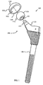
- FIG. 1 a prosthetic device in the form of a prosthetic hip joint 100 is shown in a disassembled configuration.
- the prosthetic hip joint 100 includes an acetabular cup 102 and a femoral component 104.
- the femoral component 104 includes a femoral head 106 (or "ball"), and a femoral stem 108.
- the femoral head 106 is configured for attachment to the femoral stem 108.
- the femoral head 106 can slide against the acetabular cup 102.
- the acetabular cup 102 is the part of the prosthetic hip joint 100 that forms the socket of a ball-and-socket structure.
- the acetabular cup 102 includes a convex outer surface 110 configured for engagement with a patient's acetabulum and a concave interior surface 112 configured to engage the femoral head 106.
- the cup 102 includes a lip 114 which defines a rim in a peripheral region and which extends between the convex outer surface 110 and the concave interior surface 112.
- the convex outer surface 110 of the acetabular cup 102 may be provided as part of a shell including a biocompatible material.
- the shell will generally be made from a relatively rigid material, such as a biocompatible metal or ceramic.
- the shell may be made from titanium or its alloys, or from a cobalt chromium alloy.
- the concave interior surface 112 of the cup 102 may be in the form of a liner that provides a bearing surface for the acetabular cup 102.
- the liner may be comprised of a biocompatible material that offers a low coefficient of friction, such as polyethylene.
- the liner may be made from a metal or ceramic.
- the femoral component 104 is used to replace the natural head of a femur.
- the femoral head 106 includes a generally ball-shaped outer surface 116 designed and dimensioned to be received at least partially within the cavity defined by the concave interior surface 112 of the acetabular cup 102.
- the femoral head 106 includes a generally conical bore 118 which is used to fix femoral head 106 to a Morse taper 120 on the neck 122 which extends from the femoral stem 108.
- the femoral component 104 is comprised of a relatively rigid biocompatible material such as a ceramic or metal.
- the ball 106 may be made form a cobalt chromium alloy or a stainless steel.
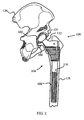
- the prosthetic hip joint 100 may be implanted in a patient by securing the acetabular cup 102 in the acetabulum 124 of the pelvis 126. Also, the femoral component 104 is secured to the femur 128 by inserting the femoral stem 108 within the intramedullary cavity 130 of the femur 128. The femoral head 106 which extends from the neck 122 is brought into slideable contact with the acetabular cup 102 such that the femoral head 106 is allowed to articulate within the acetabular cup 102. This slideable relationship provides for a ball and socket type joint.
- FIG. 3 An enlarged cutaway view of the acetabular cup 102 showing the femoral head 106, with the head 106 slightly removed from engagement with the cup 102 is shown in FIG. 3 .
- the configuration of the head 106 defines different zones or regions for the prosthesis, including a primary contact zone A and a toroidal zone T.
- primary contact zone refers to a region of the head 106 which provides the main contact area between the head 106 and the cup 102 for most joint movements once implanted in a patient. Accordingly, with reference to FIG. 3 , the convex bearing surface 116 of the head 106 primarily articulates with the concave bearing surface 112 of the cup 102 within the primary contact zone A. Some contact, however, occurs between the head 106 and the cup 102 within the toroidal zone T, particularly with certain extra-ordinary movements by the patient.
- the primary contact zone A is shown as lying within the region subtended by the angle ⁇ having a vertex at an origin 140 of the spherical cap portion. This means that the primary contact zone A is provided within a perimeter defined by the intersection of a cone 142 with the convex outer surface 116 of the head 106, the cone 142 having an apex 144 at the origin 140 and an aperture or "opening angle" ⁇ . As shown in FIG. 3 , the cone 142 is symmetrical about an axis 146 extending through the origin 140.
- the toroidal zone T extends from the primary contact zone A to the conical bore 118.
- the acetabular cup 102 shown in FIG. 3 is centred upon and symmetrical with respect to an apex 148, which is the deepest portion of the cup 102, in the coronal plane.
- the apex 148 of the concave bearing surface 112 of the cup 102 is shown in FIG. 3 aligned with the axis 146.
- the cup 102 and head 106 are generally aligned in the implanted position such that the apex 148 of the cup 102 is about 30° off the axis 146 of the head 106 in the coronal plane and about 15° off the axis 146 of the head 106 in the sagittal plane.
- the articulation area on the head is independent of the cup orientation.
- the outer surface 116 of the head 106 at any given point is defined by a radius of curvature (R H ).
- the head 106 does not form a perfect sphere, however, and the radius of curvature R H is different at different points on the surface 116 of the head 106 as shown in FIG. 4 .
- the radius of curvature in the primary contact zone (R P ) in the embodiment of FIG. 3 is 18.035 mm, while the radius of curvature in the toroidal zone (R T ) is 18.0120 mm.
- FIG. 4 depicts a slice of the femoral head 106 taken along the plane defined by the axis 146 and an axis 152 which is perpendicular to the axis 146 and which intersects the origin 140.
- the portion of the circle 150 which is behind the slice of the ball 106 as depicted in FIG. 5 is shown as a dashed line.
- the circle 150 has a radius of 0.0155 mm and lies within a plane that is located 0.0510 mm above the origin 140 and positioned perpendicular to the axis 152.
- any given point on the outer surface 116 in the toroidal zone T is defined by an R T having an origin located on the point of the circle 150 farthest away from the point being defined.
- the arc 154 of the surface 116 shown in FIG. 5 is defined by sweeping R T from the position shown as R T1 to the position of R T1' while maintaining the origin of the R T at the point 156.
- the arc 158 of the surface 116 of FIG. 5 is defined by sweeping R T from the position shown as R T2 to the position of R T2' while maintaining the origin of the R T at the point 160.
- the origin of the R T shown in FIG. 4 is located at a point 0.0510 mm above the axis 152 and 0.0155 to the left of the axis 146.
- the toroidal zone T is thus formed as the lemon of a spindle torus.
- a spindle torus is formed by the revolution of a circle about an axis coplanar with the circle.
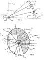
- a cross sectional view of a torus 162 is shown in FIG. 6 while FIG. 7 is a three-dimensional representation of the bottom half of the torus 162.
- the torus 162 in cross-section presents two overlapping circles 164 and 166.
- the centres 168 and 170 of the circles 164 and 166 are points on a circle 172.
- the circle 172 is thus the circular origin of the torus 162 having a radius of curvature 174 which is the radius of the circles 164 and 166.
- the outer surface 178 of the torus is referred to as the "apple” shape while the inner surface 180 is referred to as the "lemon" shape.
- FIG. 9 is identical to FIG. 8 with the exception that the origin 184 of the circle 182 has been positioned closer to the axis 186 defined by the circular origin of the outer surface 178.
- the cap portion 192 becomes smaller.
- the shape can be further modified by moving the origin 184 closer to one or the other of the centres 168 and 170. Consequently, the location and extent of the discontinuity between the cap portion 192 and the outer surface 180 can be modified.
- the spherical cap portion 192 becomes smaller.
- a cap portion with a 95° opening angle is obtained by positioning the origin of the spherical cap portion 0.051 mm below the plane of the circular origin.
- FIG. 10 is identical to FIG. 8 with the exception that the diameter of the circular origin 172 of the outer surface 178 is reduced.
- two centres 168 and 170 of the circles 164 and 166 are positioned more closely together.
- the shape of the inner surface 180 becomes more circular, thereby increasing the size of the cap portion 192. Consequently, the location and extent of the discontinuity between the cap portion 192 and the outer surface 180 can be modified.
- the radius of the circle 182 may be shorter or longer than the radii of the circles 164 and 166 in certain embodiments. Similarly, the radius of the circle 182 may be the same, shorter or longer than the radius or radii of a particular cup.
- the acetabular cup 102 is defined by a radius of curvature (R C ).
- the radius of curvature extends from the virtual centre of the cup 102, which as depicted in FIG. 3 is coincident with the origin 140, to the concave inner surface 112 of the acetabular cup 102.
- the radius of curvature is constant for all points on the concave inner surface 112 such that the concave inner surface 112 of the cup forms a hemisphere.
- the radius of curvature in this embodiment is 18.050 mm.
- the radial clearance (R CL ) or difference between R C and R H at a given point on the head 106 and the opposing point on the cup 102 does not necessarily translate directly into a spatial clearance between the head 106 and the cup 102.
- R CL radial clearance
- R CL is useful in quantifying the conformity between the surface of the ball 106 and the cup 102 which are in contact.
- a small R CL for a given contact area i.e. less than 0.05 mm, generally provides lower wear rates. Accordingly, the prosthetic hip joint 100 maintains an R CL less than 0.050 mm throughout the primary contact zone A.
- the toroidal zone T provides increased clearance between the ball 106 and the cup 102 at the lip 114.
- the acetabular cup 102 is exactly hemispherical.
- the width of the cup 102 at the plane defined by the lip 114 is the widest portion of the cup 102. Accordingly, when the ball 106 is centred within the cup 102 and in contact with the cup 102 along the axis 146, the origin 140 is located 0.015 mm above the plane defined by the lip 114.
- the widest diameter defined by the toroidal zone T will be located on a plane positioned 0.066 mm above the plane defined by the lip 114.
- the width of the toroidal zone is 35.993 mm.
- the width of the cup 102 on a plane located 0.066 mm above the plane defined by the lip 114 is 36.0998 mm.
- the clearance is 0.1068 mm.
- the width of the toroidal zone T decreases to 35.9927 mm while the width of the cup increases to 36.1 mm resulting in a clearance of 0.1073 mm.
- a precisely circular ball with a radius of 18.035 mm would result in a clearance at the plane defined by the lip 114 of 0.0300 mm.
- the femoral ball 106 is rotated within the acetabular cup 102 to the maximum amount possible before dislocation would occur in an implanted device.
- the contact area between the ball 106 and the cup 102 for purposes of this example is centred at location 196.
- This configuration which is not a normally occurring configuration, provides insight into the smallest expected clearance for the embodiment of FIG. 3 . That is, as the contact area is located more fully within the cup 102 with the ball 106 rotated as shown in FIG. 6 , the origin 140 of the spherical cap portion moves off of the plane defined by the lip 114, thereby increasing the clearance at the lip 114.
- the conformity is achieved while providing increased clearance on the plane defined by the lip 114.
- FIG. 12 An alternative embodiment of an acetabular cup 200 is shown in FIG. 12 .
- the acetabular cup 200 includes an outer surface 202 and an inner surface 204.
- the inner surface 204 includes a cap portion 206 formed on a circle 208 with a centre 210 and a toroidal portion 212.
- the toroidal portion 212 is shown in cross-section as formed on two circles 214 and 216 having centres 218 and 220, respectively.
- the centre 208 is located above the axis 222 defined by the centres 218 and 220.
- the toroidal portion 212 is formed on the apple or outer surface of the torus defined by the rotation of the circles 214 and 216. Accordingly, even if each of the circles 208, 214 and 216 have the same diameter, the diameter of the cup 200 in the toroidal portion 212 will be greater than the diameter in the cap portion 206.
- FIG. 13 shows an acetabular cup 230 includes an outer surface 232 and an inner surface 234.
- the inner surface 234 includes a cap portion 236 formed on a circle 238 with a centre 240 and a toroidal portion 242.
- the toroidal portion 242 is shown in cross-section as formed on two circles 244 and 246 having centres 248 and 250, respectively.
- the centre 238 is located above the axis 252 defined by the centres 248 and 250.
- the toroidal portion 242 is formed on the apple or outer surface of the torus defined by the rotation of the circles 244 and 246. Accordingly, even if each of the circles 238, 244 and 246 have the same diameter, the diameter of the cup 230 in the toroidal portion 242 will be greater than the diameter in the cap portion 236. Additionally, the cap portion 236 is centred at a location 254 which is offset from the apex 256 or deepest portion of the cup 230. Thus, the cap portion 236 is centred on the normal contact area between a ball and the cup 230 when the ball and cup 230 are implanted. Accordingly, most of the contact between a ball and the cup 236 when implanted will occur within the cap portion 236.
Description
- This invention relates to the field of joint prostheses, in particular hip joint prostheses.
- A common orthopaedic joint prosthesis includes a ball and cup arrangement. For example, hip joints typically comprise a rounded femoral head and an acetabular cup. The rounded femoral head is provided on a stem that is configured to engage the intramedullary cavity of the femur and secure the head on the femur. The rounded femoral head includes a convex surface configured to engage a concave surface on the acetabular cup. The acetabular cup is configured for implantation on the acetabulum of the pelvis. When the rounded femoral head is received within the acetabular cup, a ball and socket joint is provided.
- In order to reduce wear between the components of the joint prosthesis, the components are manufactured such that the clearance between the bearing surfaces is minimized. The term "clearance" is often used in reference to a "diametral clearance" between the head and cup parts of a joint prosthesis. The diametral clearance between bearing surfaces is generally considered to be the difference between the diameters of the bearing surface of the ball and the bearing surface of the cup.
- While minimal diametral clearance between the bearing surfaces is desired, at least two factors limit the reduction of clearances. First, manufacturing tolerances generally limit the extent to which clearances may be reduced. For example, for diametral clearances below the 15 to 30 µm range, it has been observed that imperfect formation of the femoral head and the acetabular cup contributes to local interferences and small deformations that result in wear.
- Second, acetabular cup deformation during implantation into the acetabulum also limits the degree to which clearances may be reduced in a hip joint prosthesis. This deformation generally occurs near the equatorial lip of the acetabular cup. For approximately spherical cup and head arrangements, reduction in clearances near the pole of the head also means reduction in clearances near the equatorial lip. In other words, when the head and the cup of a hip prosthesis are substantially spherical, the small clearances near the pole of the head are also found in the region near the equatorial lip of the cup. Thus, when cup deformation occurs near the equatorial lip in a low clearance spherical design, interference is likely to occur between the equatorial lip of the cup and the ball.
- One way to reduce clearance complications resulting from acetabular cup deformation is to provide a conformal region having a small clearance near the centre of the primary articulation area of the femoral head, and a peripheral region surrounding the conformal region, in which the peripheral region has a significantly greater clearance than the conformal region, including a significantly greater clearance near the lip of the cup. With this arrangement, deformations near the equatorial lip of the acetabular cup are less likely to result in obstruction with the femoral head because of the increased clearance near the equatorial lip. Although several of these arrangements have been provided in the past, they have not provided optimal solutions. In particular, many of these arrangements include peripheral regions surrounding the conformal region where the clearances in these peripheral regions quickly diverge from the relatively small clearances in the conformal zone. However, when the clearance in the peripheral region is too great, significant wear may result.
-
WO 97/16138 -
DE-A-44 28 290 discloses inFigure 3 a spherical ball member and a toroidal cup member. - Accordingly, what is needed is a joint prosthesis configured to avoid interference between the ball and cup even if the equatorial region of the cup is deformed during implantation. It would also be advantageous if the clearance between the ball and cup could remain relatively low even in a peripheral region surrounding the conformal region.
- In one aspect, the present invention provides a joint system which is defined by the features of
claim 1. - In another aspect, the invention provides a joint system which is defined by the features of claim 3.
- Embodiments of the invention are described below by way of example with reference to the accompanying drawings, in which:
-
FIG. 1 is a perspective view of various components of a hip prosthesis including an acetabular cup, a femoral head, and a femoral stem in accordance with principles of the invention; -
FIG. 2 is a cutaway view of the hip prosthesis ofFIG. 1 assembled and implanted in a pelvis and femur; -
FIG. 3 is a cross-sectional view of the femoral head and acetabular cup ofFIG. 1 ; -
FIG. 4 is a diagrammatic representation of the radii which define the inner surface of the cup, a primary contact zone and a toroidal zone in accordance with principles of the invention; -
FIG. 5 depicts a perspective view of a slice of the femoral head ofFIG. 3 showing the relative positions of the origin for the radius of curvature of the cap portion of the femoral head and the circular origin of the radius of curvature of the toroidal section; -
FIG. 6 is a cross sectional view of a spindle torus; -
FIG. 7 is a three-dimensional representation of the bottom half of the torus ofFIG. 6 including the apple shaped or outer surface and the lemon shaped or inner surface of the torus; -
FIG. 8 is a diagrammatic representation of the definition of the outer surface of a femoral ball using the lemon shape or inner surface of a spindle torus and an arc of a circle centred below the axis defined by the centre of the circle (the circular origin) which defines the spindle torus; -
FIG. 9 is a diagrammatic representation of the circles ofFIG. 8 with the centre of the circle used to define the arc or cap portion closer to the axis defined by the centre of the circle (the circular origin) thereby decreasing the size of the cap portion as compared withFIG. 8 ; -
FIG. 10 is a diagrammatic representation of the circles ofFIG. 8 with the centre of the circle used to define the arc or cap portion at the same distance away from the axis defined by the centre of the circle (the circular origin) as shown inFIG. 8 but with the diameter of the circular origin reduced (i.e. the apple shaped portion is more circular) thereby increasing the size of the cap portion as compared withFIG. 8 ; -
FIG. 11 is a cross-sectional view of the femoral head and acetabular cup ofFIG. 1 with the femoral head rotated within the acetabular cup and contacting the acetabular cup at the opening of the acetabular cup; -
FIG. 12 is a cross-sectional view of an alternative embodiment of an acetabular cup with a diagrammatic overlay showing the use of a toroidal surface within the acetabular cup in accordance with principles of the invention; and -
FIG. 13 is a cross-sectional view of an alternative embodiment of an acetabular cup with a diagrammatic overlay showing the use of a toroidal surface within the acetabular cup in which the cap portion and toroidal portion of the acetabular cup are not centred within the acetabular cup in accordance with principles of the invention. - Referring to the drawings,
FIG. 1 , a prosthetic device in the form of aprosthetic hip joint 100 is shown in a disassembled configuration. Theprosthetic hip joint 100 includes anacetabular cup 102 and afemoral component 104. Thefemoral component 104 includes a femoral head 106 (or "ball"), and afemoral stem 108. Thefemoral head 106 is configured for attachment to thefemoral stem 108. Thefemoral head 106 can slide against theacetabular cup 102. - The
acetabular cup 102 is the part of theprosthetic hip joint 100 that forms the socket of a ball-and-socket structure. Theacetabular cup 102 includes a convexouter surface 110 configured for engagement with a patient's acetabulum and a concaveinterior surface 112 configured to engage thefemoral head 106. Thecup 102 includes alip 114 which defines a rim in a peripheral region and which extends between the convexouter surface 110 and the concaveinterior surface 112. - The convex
outer surface 110 of theacetabular cup 102 may be provided as part of a shell including a biocompatible material. The shell will generally be made from a relatively rigid material, such as a biocompatible metal or ceramic. For example, the shell may be made from titanium or its alloys, or from a cobalt chromium alloy. The concaveinterior surface 112 of thecup 102 may be in the form of a liner that provides a bearing surface for theacetabular cup 102. The liner may be comprised of a biocompatible material that offers a low coefficient of friction, such as polyethylene. Alternatively, the liner may be made from a metal or ceramic. - The
femoral component 104 is used to replace the natural head of a femur. To this end, thefemoral head 106 includes a generally ball-shapedouter surface 116 designed and dimensioned to be received at least partially within the cavity defined by the concaveinterior surface 112 of theacetabular cup 102. Thefemoral head 106 includes a generallyconical bore 118 which is used to fixfemoral head 106 to a Morsetaper 120 on theneck 122 which extends from thefemoral stem 108. Thefemoral component 104 is comprised of a relatively rigid biocompatible material such as a ceramic or metal. For example, theball 106 may be made form a cobalt chromium alloy or a stainless steel. - As shown in
FIG. 2 , theprosthetic hip joint 100 may be implanted in a patient by securing theacetabular cup 102 in theacetabulum 124 of thepelvis 126. Also, thefemoral component 104 is secured to thefemur 128 by inserting thefemoral stem 108 within theintramedullary cavity 130 of thefemur 128. Thefemoral head 106 which extends from theneck 122 is brought into slideable contact with theacetabular cup 102 such that thefemoral head 106 is allowed to articulate within theacetabular cup 102. This slideable relationship provides for a ball and socket type joint. - An enlarged cutaway view of the
acetabular cup 102 showing thefemoral head 106, with thehead 106 slightly removed from engagement with thecup 102 is shown inFIG. 3 . The configuration of thehead 106 defines different zones or regions for the prosthesis, including a primary contact zone A and a toroidal zone T. - The term "primary contact zone" refers to a region of the
head 106 which provides the main contact area between thehead 106 and thecup 102 for most joint movements once implanted in a patient. Accordingly, with reference toFIG. 3 , theconvex bearing surface 116 of thehead 106 primarily articulates with theconcave bearing surface 112 of thecup 102 within the primary contact zone A. Some contact, however, occurs between thehead 106 and thecup 102 within the toroidal zone T, particularly with certain extra-ordinary movements by the patient. - The primary contact zone A is shown as lying within the region subtended by the angle α having a vertex at an
origin 140 of the spherical cap portion. This means that the primary contact zone A is provided within a perimeter defined by the intersection of acone 142 with the convexouter surface 116 of thehead 106, thecone 142 having an apex 144 at theorigin 140 and an aperture or "opening angle" α. As shown inFIG. 3 , thecone 142 is symmetrical about anaxis 146 extending through theorigin 140. The toroidal zone T extends from the primary contact zone A to theconical bore 118. - It has been shown that contact occurs predominantly in an area defined by opening angles between 85 and 145° (see for example Bergmann et al, "Hip contact forces and gait patterns from routine activities", J Biomech, 2001, 34(7), 859-871). Accordingly, while the angle α in this embodiment is 95°, other opening angles between 85 and 145° may be used. Selection of opening angles between 95 and 125° provides for good radial clearance which is discussed below.
- The
acetabular cup 102 shown inFIG. 3 is centred upon and symmetrical with respect to an apex 148, which is the deepest portion of thecup 102, in the coronal plane. In particular, theapex 148 of theconcave bearing surface 112 of thecup 102 is shown inFIG. 3 aligned with theaxis 146. When thecup 102 is in this position relative to thehead 106, it is considered to be in a centred position. In practice, thecup 102 andhead 106 are generally aligned in the implanted position such that the apex 148 of thecup 102 is about 30° off theaxis 146 of thehead 106 in the coronal plane and about 15° off theaxis 146 of thehead 106 in the sagittal plane. For a spherical cup geometry, the articulation area on the head is independent of the cup orientation. - With continued reference to
FIG. 3 , theouter surface 116 of thehead 106 at any given point is defined by a radius of curvature (RH). Thehead 106 does not form a perfect sphere, however, and the radius of curvature RH is different at different points on thesurface 116 of thehead 106 as shown inFIG. 4 . The radius of curvature in the primary contact zone (RP) in the embodiment ofFIG. 3 is 18.035 mm, while the radius of curvature in the toroidal zone (RT) is 18.0120 mm. - Moreover, as shown in
FIG. 4 , the origin of the RP is located at theorigin 140. The origin of the RT, however, is defined by acircle 150 shown inFIG. 5. FIG. 5 depicts a slice of thefemoral head 106 taken along the plane defined by theaxis 146 and anaxis 152 which is perpendicular to theaxis 146 and which intersects theorigin 140. The portion of thecircle 150 which is behind the slice of theball 106 as depicted inFIG. 5 is shown as a dashed line. Thecircle 150 has a radius of 0.0155 mm and lies within a plane that is located 0.0510 mm above theorigin 140 and positioned perpendicular to theaxis 152. - Any given point on the
outer surface 116 in the toroidal zone T is defined by an RT having an origin located on the point of thecircle 150 farthest away from the point being defined. For example, thearc 154 of thesurface 116 shown inFIG. 5 is defined by sweeping RT from the position shown as RT1 to the position of RT1' while maintaining the origin of the RT at thepoint 156. Similarly, thearc 158 of thesurface 116 ofFIG. 5 is defined by sweeping RT from the position shown as RT2 to the position of RT2' while maintaining the origin of the RT at thepoint 160. Thus, the origin of the RT shown inFIG. 4 is located at a point 0.0510 mm above theaxis 152 and 0.0155 to the left of theaxis 146. - From a mathematical construct, the toroidal zone T is thus formed as the lemon of a spindle torus. A spindle torus is formed by the revolution of a circle about an axis coplanar with the circle. A cross sectional view of a
torus 162 is shown inFIG. 6 whileFIG. 7 is a three-dimensional representation of the bottom half of thetorus 162. Thetorus 162 in cross-section presents two overlappingcircles centres circles circle 172. Thecircle 172 is thus the circular origin of thetorus 162 having a radius ofcurvature 174 which is the radius of thecircles outer surface 178 of the torus is referred to as the "apple" shape while theinner surface 180 is referred to as the "lemon" shape. - As shown in
FIG. 8 , thelemon 180 and acircle 182 having acentre 184 located below theaxis 186 defined by thecentres circles cap 192.FIG. 9 is identical toFIG. 8 with the exception that theorigin 184 of thecircle 182 has been positioned closer to theaxis 186 defined by the circular origin of theouter surface 178. As is apparent from comparingFIG. 9 withFIG. 8 , as theorigin 184 of thecircle 182 approaches theaxis 186, thecap portion 192 becomes smaller. The shape can be further modified by moving theorigin 184 closer to one or the other of thecentres cap portion 192 and theouter surface 180 can be modified. - Thus, by moving the origin or
centre 184 closer to the axis defined by the circular origin, thespherical cap portion 192 becomes smaller. For example, given a circular origin diameter of 0.031 mm, an RP of 18.035 mm and an RT of 18.0120 mm, a cap portion with a 95° opening angle is obtained by positioning the origin of the spherical cap portion 0.051 mm below the plane of the circular origin. In the event a cap portion with a 125° opening angle is desired using the same radii, it is only necessary to know the position the origin of the spherical cap portion at about 0.08 mm below the plane of the circular origin. -
FIG. 10 is identical toFIG. 8 with the exception that the diameter of thecircular origin 172 of theouter surface 178 is reduced. Thus, twocentres circles FIG. 10 withFIG. 8 , as the twocentres circles circular origin 172 is shortened, the shape of theinner surface 180 becomes more circular, thereby increasing the size of thecap portion 192. Consequently, the location and extent of the discontinuity between thecap portion 192 and theouter surface 180 can be modified. - Moreover, while the
circles circle 182 may be shorter or longer than the radii of thecircles circle 182 may be the same, shorter or longer than the radius or radii of a particular cup. - Returning to
FIG. 3 , theacetabular cup 102 is defined by a radius of curvature (RC). The radius of curvature extends from the virtual centre of thecup 102, which as depicted inFIG. 3 is coincident with theorigin 140, to the concaveinner surface 112 of theacetabular cup 102. The radius of curvature is constant for all points on the concaveinner surface 112 such that the concaveinner surface 112 of the cup forms a hemisphere. The radius of curvature in this embodiment is 18.050 mm. - The radial clearance (RCL) or difference between RC and RH at a given point on the
head 106 and the opposing point on the cup 102 (that is, on a given line extending from theorigin 140 of thehead 106 to theconcave surface 112 of the cup 102) does not necessarily translate directly into a spatial clearance between thehead 106 and thecup 102. For example, when theprosthesis 100 is implanted and thehead 106 is in a centred position, thehead 106 is in contact with thecup 102, even though the RCL is 0.015 mm (derived as the difference between RC (18.050 mm) and RP (18.035 mm)). The value of RCL, however, is useful in quantifying the conformity between the surface of theball 106 and thecup 102 which are in contact. For example, a small RCL for a given contact area, i.e. less than 0.05 mm, generally provides lower wear rates. Accordingly, theprosthetic hip joint 100 maintains an RCL less than 0.050 mm throughout the primary contact zone A. - Additionally, the toroidal zone T provides increased clearance between the
ball 106 and thecup 102 at thelip 114. With reference to the embodiment ofFIG. 3 , theacetabular cup 102 is exactly hemispherical. Thus, the width of thecup 102 at the plane defined by thelip 114 is the widest portion of thecup 102. Accordingly, when theball 106 is centred within thecup 102 and in contact with thecup 102 along theaxis 146, theorigin 140 is located 0.015 mm above the plane defined by thelip 114. Thus, the widest diameter defined by the toroidal zone T will be located on a plane positioned 0.066 mm above the plane defined by thelip 114. At this location, the width of the toroidal zone is 35.993 mm. The width of thecup 102 on a plane located 0.066 mm above the plane defined by thelip 114 is 36.0998 mm. Thus, the clearance is 0.1068 mm. - At the plane defined by the
lip 114, however, the width of the toroidal zone T decreases to 35.9927 mm while the width of the cup increases to 36.1 mm resulting in a clearance of 0.1073 mm. In contrast, a precisely circular ball with a radius of 18.035 mm would result in a clearance at the plane defined by thelip 114 of 0.0300 mm. - Referring to
FIG. 11 , thefemoral ball 106 is rotated within theacetabular cup 102 to the maximum amount possible before dislocation would occur in an implanted device. The contact area between theball 106 and thecup 102 for purposes of this example is centred atlocation 196. This configuration, which is not a normally occurring configuration, provides insight into the smallest expected clearance for the embodiment ofFIG. 3 . That is, as the contact area is located more fully within thecup 102 with theball 106 rotated as shown inFIG. 6 , theorigin 140 of the spherical cap portion moves off of the plane defined by thelip 114, thereby increasing the clearance at thelip 114. The width of theball 106 in the plane defined by thelip 114 in the configuration ofFIG. 6 is 36.04699 mm resulting in a clearance of 0.0530 mm. In contrast, a precisely circular ball with a radius of 18.035 mm in the configuration ofFIG. 6 would result in a clearance at the plane defined by thelip 114 of 0.0300 mm. - Thus, while the configuration of the
prosthetic hip joint 100 provides the desired conformity between theball 106 and thecup 102 regardless of the orientation of theball 106 within thecup 102, the conformity is achieved while providing increased clearance on the plane defined by thelip 114. - An alternative embodiment of an
acetabular cup 200 is shown inFIG. 12 . Theacetabular cup 200 includes anouter surface 202 and aninner surface 204. Theinner surface 204 includes acap portion 206 formed on acircle 208 with acentre 210 and atoroidal portion 212. Thetoroidal portion 212 is shown in cross-section as formed on twocircles centres centre 208 is located above the axis 222 defined by thecentres toroidal portion 212 is formed on the apple or outer surface of the torus defined by the rotation of thecircles circles cup 200 in thetoroidal portion 212 will be greater than the diameter in thecap portion 206. - As noted above, a cup and head are generally aligned in the implanted position such that the apex of the cup is about 30° off the axis of the head in the coronal plane and about 15° off the axis of the head in the sagittal plane. Accordingly, it may be desired to modify the location of the cap portion of a cup. For example,
FIG. 13 shows anacetabular cup 230 includes anouter surface 232 and aninner surface 234. Theinner surface 234 includes acap portion 236 formed on acircle 238 with acentre 240 and atoroidal portion 242. Thetoroidal portion 242 is shown in cross-section as formed on twocircles centres centre 238 is located above theaxis 252 defined by thecentres - In this embodiment, the
toroidal portion 242 is formed on the apple or outer surface of the torus defined by the rotation of thecircles circles cup 230 in thetoroidal portion 242 will be greater than the diameter in thecap portion 236. Additionally, thecap portion 236 is centred at a location 254 which is offset from the apex 256 or deepest portion of thecup 230. Thus, thecap portion 236 is centred on the normal contact area between a ball and thecup 230 when the ball andcup 230 are implanted. Accordingly, most of the contact between a ball and thecup 236 when implanted will occur within thecap portion 236.
Claims (3)
- A prosthetic ball and cup joint system comprising:a cup member (102) for attachment to a first bone in a joint, the cup member defining cavity having a concave articulation surface which is defined by a first radius of curvature (RG), anda ball member (106) for attachment to a second bone in the joint which includes:(a) a cap portion having a first convex articulation surface which forms part of a sphere and has a second radius of curvature (RP), and(b) a toroidal portion having a second convex articulation surface which is defined by the lemon portion of a spindle torus and has a third radius of curvature (RT), the spindle torus being formed using a circular origin located on a plane that is perpendicular to an axis (146) extending through the origin (140) of the second radius of curvature and through the centre of the first articulation surface,in which each of the second radius of curvature and the third radius of curvature has a length that is different from the length of the first radius of curvature by less than 0.05 mm and in which the origin of the second radius of curvature is not coincident with the origin of the third radius of curvature.
- The system of claim 1, in which the angle defining a primary contact zone A and subtended at the centre of the ball member by the cap portion is between 85 and 145°.
- A prosthetic ball and cup joint system comprising:a ball member for attachment to a first bone in a joint, the ball member having a convex articulation surface defined by a first radius of curvature, anda cup member (200) for attachment to a second bone in the joint, the cup member defining a cavity which includes:(a) a cap portion (206) having a first concave articulation surface which forms part of a sphere and has a second radius of curvature, and(b) a toroidal portion (212) having a second concave articulation surface which is defined by the apple portion of a spindle torus and has a third radius of curvature, the spindle torus being formed using a circular origin located on a plane that is perpendicular to an axis extending through the origin of the second radius of curvature and through the centre of the first articulation surface, in which each of the second radius of curvature and the third radius of curvature has a length that is different from the length of the first radius of curvature by less than 0.05 mm and in which the origin of the second radius of curvature is not coincident with the origin of the third radius of curvature.
Priority Applications (1)
| Application Number | Priority Date | Filing Date | Title |
|---|---|---|---|
| EP13187591.6A EP2754420B1 (en) | 2007-12-28 | 2008-12-11 | Aspherical hip bearing component |
Applications Claiming Priority (1)
| Application Number | Priority Date | Filing Date | Title |
|---|---|---|---|
| US12/005,837 US7985262B2 (en) | 2007-12-28 | 2007-12-28 | Aspheric hip bearing couple |
Related Child Applications (2)
| Application Number | Title | Priority Date | Filing Date |
|---|---|---|---|
| EP13187591.6A Division EP2754420B1 (en) | 2007-12-28 | 2008-12-11 | Aspherical hip bearing component |
| EP13187591.6A Division-Into EP2754420B1 (en) | 2007-12-28 | 2008-12-11 | Aspherical hip bearing component |
Publications (2)
| Publication Number | Publication Date |
|---|---|
| EP2074965A1 EP2074965A1 (en) | 2009-07-01 |
| EP2074965B1 true EP2074965B1 (en) | 2014-04-30 |
Family
ID=40589983
Family Applications (2)
| Application Number | Title | Priority Date | Filing Date |
|---|---|---|---|
| EP08171397.6A Active EP2074965B1 (en) | 2007-12-28 | 2008-12-11 | Aspherical hip bearing component |
| EP13187591.6A Active EP2754420B1 (en) | 2007-12-28 | 2008-12-11 | Aspherical hip bearing component |
Family Applications After (1)
| Application Number | Title | Priority Date | Filing Date |
|---|---|---|---|
| EP13187591.6A Active EP2754420B1 (en) | 2007-12-28 | 2008-12-11 | Aspherical hip bearing component |
Country Status (2)
| Country | Link |
|---|---|
| US (4) | US7985262B2 (en) |
| EP (2) | EP2074965B1 (en) |
Families Citing this family (13)
| Publication number | Priority date | Publication date | Assignee | Title |
|---|---|---|---|---|
| US8579985B2 (en) | 2006-12-07 | 2013-11-12 | Ihip Surgical, Llc | Method and apparatus for hip replacement |
| US8974540B2 (en) * | 2006-12-07 | 2015-03-10 | Ihip Surgical, Llc | Method and apparatus for attachment in a modular hip replacement or fracture fixation device |
| CA2671523C (en) | 2006-12-07 | 2013-02-12 | Anatol Podolsky | Method and apparatus for total hip replacement |
| US7985262B2 (en) | 2007-12-28 | 2011-07-26 | Depuy Products, Inc. | Aspheric hip bearing couple |
| GB0901795D0 (en) * | 2009-02-04 | 2009-03-11 | Smith & Nephew | Medical device and method |
| US8142511B2 (en) | 2010-04-19 | 2012-03-27 | Zimmer, Inc. | Bi-material prosthesis component |
| US20130304225A1 (en) * | 2012-05-08 | 2013-11-14 | Richard D. Komistek | Optimal contact mechanics for a tha |
| AU2013323337B2 (en) | 2012-09-27 | 2018-02-15 | The General Hospital Corporation D/B/A Massachusetts General Hospital | Femoral heads, mobile inserts, acetabular components, and modular junctions for orthopedic implants and methods of using femoral heads, mobile inserts, acetabular components, and modular junctions for orthopedic implants |
| SG11201912367UA (en) | 2017-06-19 | 2020-01-30 | Harpoon Medical Inc | Method and apparatus for cardiac procedures |
| CN111372525B (en) | 2017-10-24 | 2023-08-04 | 马里兰大学巴尔的摩分校 | Method and apparatus for cardiac procedure |
| US11638647B2 (en) * | 2018-03-09 | 2023-05-02 | Rafael Eduardo PEREZ NUNEZ | Prosthesis for hip replacement with polyethylene head and anti-rotational intra-prosthetic assembly |
| BR112020019028A2 (en) * | 2018-05-07 | 2020-12-29 | Ceramtec Gmbh | INSERT FOR A SLIDING PAIR WITH A SPHERICAL SLIDING PARTNER |
| KR20210006903A (en) * | 2018-05-07 | 2021-01-19 | 세람테크 게엠베하 | Implants for wear engagement with spherical wear partners |
Family Cites Families (41)
| Publication number | Priority date | Publication date | Assignee | Title |
|---|---|---|---|---|
| CH449173A4 (en) | 1966-09-02 | 1968-04-11 | ||
| US3510883A (en) | 1967-10-30 | 1970-05-12 | Robert F Cathcart | Joint prosthesis |
| FR2134170B1 (en) | 1971-04-23 | 1974-03-08 | Benoist Girard & Cie | |
| CH593054A5 (en) * | 1975-06-18 | 1977-11-15 | Sulzer Ag | |
| US4840632A (en) | 1984-03-16 | 1989-06-20 | Kampner Stanley L | Hip prosthesis |
| CH667988A5 (en) | 1985-11-18 | 1988-11-30 | Sulzer Ag | ARTIFICIAL HIP PAN. |
| AT386948B (en) | 1987-07-09 | 1988-11-10 | Menschik Alfred Dr | ARTIFICIAL HIP JOINT |
| GB2260705A (en) | 1991-10-08 | 1993-04-28 | Kevin Hardinge | Ceramic/metal prosthesis |
| DE4232313C1 (en) * | 1992-09-26 | 1994-04-28 | Kubein Meesenburg Dietmar | Artificial joint as an endoprosthesis for the human shoulder joint |
| US5443519A (en) | 1993-04-22 | 1995-08-22 | Implex Corporation | Prosthetic ellipsoidal acetabular cup |
| FR2706284B1 (en) * | 1993-06-17 | 1995-09-29 | Roux Christiane | Cotyloid prosthesis, in particular for coxo-femoral articulation. |
| CA2133718A1 (en) | 1993-10-18 | 1995-04-19 | Gene M. Farling | Non-spherical acetabular cup for total hip replacement |
| US5522900A (en) * | 1993-12-17 | 1996-06-04 | Avanta Orthopaedics | Prosthetic joint and method of manufacture |
| CA2142634C (en) | 1994-02-18 | 2005-09-20 | Salvatore Caldarise | Self-lubricating implantable articulation member |
| GB9404077D0 (en) | 1994-03-03 | 1994-04-20 | Univ Leeds | Acetabular cup |
| DE4428290A1 (en) | 1994-08-10 | 1996-02-15 | Kubein Meesenburg Dietmar | Artificial replacement joint for human |
| US5609643A (en) | 1995-03-13 | 1997-03-11 | Johnson & Johnson Professional, Inc. | Knee joint prosthesis |
| US6059830A (en) * | 1995-11-02 | 2000-05-09 | Wright Medical Technology, Inc. | Low wear ball and cup joint prosthesis |
| PL186803B1 (en) * | 1996-04-12 | 2004-02-27 | Ct Pulse Orthopedics Ltd | Artificial joint in particular a hip joint |
| US5964808A (en) * | 1996-07-11 | 1999-10-12 | Wright Medical Technology, Inc. | Knee prosthesis |
| ATE260614T1 (en) * | 1996-10-23 | 2004-03-15 | Smith & Nephew Inc | POCKET FOR HIP JOINT PROSTHESIS |
| GB9623540D0 (en) | 1996-11-12 | 1997-01-08 | Johnson & Johnson Professional | Hip joint prosthesis |
| US5928285A (en) * | 1997-05-30 | 1999-07-27 | Bristol-Myers Squibb Co. | Orthopaedic implant having an articulating surface with a conforming and translational surface |
| US5879406A (en) * | 1997-07-15 | 1999-03-09 | Saint-Gobain Industrial Ceramics, Inc. | Artificial joint bioprosthesis for mitigation of wear |
| US5972032A (en) * | 1997-12-05 | 1999-10-26 | Sulzer Orthopedics Inc. | Acetabular shell having flared rim and fixation spikes |
| DE19915814A1 (en) | 1999-04-08 | 2000-10-12 | Ceramtec Ag | Joint prosthesis; has socket and head, where one articulation surface has constant radius and other articulation surface is formed of two part surfaces, which form annular contact surface |
| GB0029318D0 (en) * | 2000-12-01 | 2001-01-17 | Depuy Int Ltd | An orthopaedic joint prosthesis |
| GB2366733B (en) | 2001-04-24 | 2002-08-07 | Corin Ltd | A hip prosthesis |
| FR2832922B1 (en) * | 2001-12-04 | 2004-08-27 | Jean Claude Bouvet | SHOULDER PROSTHESIS |
| US6660040B2 (en) | 2001-12-19 | 2003-12-09 | Depuy Orthopaedics, Inc. | Prosthetic joints having reduced area bearing surfaces and application thereof to a range of sizes of prosthetic joints |
| GB0200993D0 (en) | 2002-01-17 | 2002-03-06 | Depuy Int Ltd | Manufacturing a component with a near spherical surface |
| US6706068B2 (en) * | 2002-04-23 | 2004-03-16 | Bret A. Ferree | Artificial disc replacements with natural kinematics |
| US20040148033A1 (en) | 2003-01-24 | 2004-07-29 | Schroeder David Wayne | Wear surface for metal-on-metal articulation |
| DE10304102A1 (en) * | 2003-01-31 | 2004-08-12 | Ceram Tec Ag Innovative Ceramic Engineering | hip prosthesis |
| US20050261776A1 (en) | 2004-05-19 | 2005-11-24 | Howmedica Osteonics Corp. | Prosthetic joint with annular contact bearing surface |
| GB2424187A (en) * | 2005-03-17 | 2006-09-20 | Biomet Uk Ltd | A Joint prosthesis which includes a shell having a region intended to protrude beyond a bone surface |
| GB0519490D0 (en) | 2005-09-23 | 2005-11-02 | Benoist Girard Sas | Prosthetic joints |
| DE102007031672B4 (en) | 2006-08-04 | 2018-07-26 | Ceramtec Gmbh | Ball head with flats to prevent dry running of an artificial hip joint |
| EP2086470B1 (en) * | 2006-11-17 | 2016-12-14 | Scyon Orthopaedics AG | Wear-reducing geometry of articulations in total joint replacements |
| US8715364B2 (en) | 2007-02-05 | 2014-05-06 | DePuy Synthes Products, LLC | Aspheric hip bearing couple |
| US7985262B2 (en) | 2007-12-28 | 2011-07-26 | Depuy Products, Inc. | Aspheric hip bearing couple |
-
2007
- 2007-12-28 US US12/005,837 patent/US7985262B2/en active Active
-
2008
- 2008-12-11 EP EP08171397.6A patent/EP2074965B1/en active Active
- 2008-12-11 EP EP13187591.6A patent/EP2754420B1/en active Active
-
2011
- 2011-06-29 US US13/172,693 patent/US8652213B2/en active Active
-
2014
- 2014-01-14 US US14/154,598 patent/US9668864B2/en active Active
-
2017
- 2017-04-13 US US15/486,905 patent/US10245150B2/en active Active
Also Published As
| Publication number | Publication date |
|---|---|
| EP2754420B1 (en) | 2016-11-02 |
| EP2074965A1 (en) | 2009-07-01 |
| US10245150B2 (en) | 2019-04-02 |
| EP2754420A1 (en) | 2014-07-16 |
| US20140128989A1 (en) | 2014-05-08 |
| US7985262B2 (en) | 2011-07-26 |
| US20170216052A1 (en) | 2017-08-03 |
| US20090171466A1 (en) | 2009-07-02 |
| US9668864B2 (en) | 2017-06-06 |
| US8652213B2 (en) | 2014-02-18 |
| US20110257759A1 (en) | 2011-10-20 |
Similar Documents
| Publication | Publication Date | Title |
|---|---|---|
| EP2074965B1 (en) | Aspherical hip bearing component | |
| AU2004202927B2 (en) | Acetabular component | |
| AU2002220859B2 (en) | An orthopaedic joint prosthesis | |
| US7108720B2 (en) | Reduced wear orthopaedic implant apparatus and method | |
| EP1377237B1 (en) | Containment system for constraining a prosthetic component | |
| EP1413266B1 (en) | Orthopaedic implant having an articulating surface with a conforming area surrounded by a translational area | |
| EP1506749B1 (en) | Constrained acetabular liner | |
| EP2083759B1 (en) | Shoulder prosthesis | |
| EP1945146B1 (en) | Rotating constrained liner | |
| EP1952786B1 (en) | Aspherical hip bearing couple | |
| AU2002220859A1 (en) | An orthopaedic joint prosthesis | |
| US10307255B1 (en) | Acetabular cup assembly | |
| JP7189134B2 (en) | Lateral dual mobility assembly | |
| US8142511B2 (en) | Bi-material prosthesis component | |
| US20060200247A1 (en) | Implant and articular prosthesis comprising said implant | |
| EP1520559A1 (en) | Acetubular liner | |
| US20240074864A1 (en) | Dual mobility acetabular implant for hip revision surgery | |
| CN111194194A (en) | Prosthetic assembly for an improved so-called liner for an acetabular or glenoid cup | |
| JP2004057621A (en) | Prosthetic hip joint |
Legal Events
| Date | Code | Title | Description |
|---|---|---|---|
| PUAI | Public reference made under article 153(3) epc to a published international application that has entered the european phase |
Free format text: ORIGINAL CODE: 0009012 |
|
| AK | Designated contracting states |
Kind code of ref document: A1 Designated state(s): AT BE BG CH CY CZ DE DK EE ES FI FR GB GR HR HU IE IS IT LI LT LU LV MC MT NL NO PL PT RO SE SI SK TR |
|
| AX | Request for extension of the european patent |
Extension state: AL BA MK RS |
|
| 17P | Request for examination filed |
Effective date: 20091223 |
|
| AKX | Designation fees paid |
Designated state(s): AT BE BG CH CY CZ DE DK EE ES FI FR GB GR HR HU IE IS IT LI LT LU LV MC MT NL NO PL PT RO SE SI SK TR |
|
| 17Q | First examination report despatched |
Effective date: 20111020 |
|
| GRAJ | Information related to disapproval of communication of intention to grant by the applicant or resumption of examination proceedings by the epo deleted |
Free format text: ORIGINAL CODE: EPIDOSDIGR1 |
|
| GRAP | Despatch of communication of intention to grant a patent |
Free format text: ORIGINAL CODE: EPIDOSNIGR1 |
|
| INTG | Intention to grant announced |
Effective date: 20131001 |
|
| GRAS | Grant fee paid |
Free format text: ORIGINAL CODE: EPIDOSNIGR3 |
|
| GRAA | (expected) grant |
Free format text: ORIGINAL CODE: 0009210 |
|
| RAP1 | Party data changed (applicant data changed or rights of an application transferred) |
Owner name: DEPUY SYNTHES PRODUCTS, LLC |
|
| AK | Designated contracting states |
Kind code of ref document: B1 Designated state(s): AT BE BG CH CY CZ DE DK EE ES FI FR GB GR HR HU IE IS IT LI LT LU LV MC MT NL NO PL PT RO SE SI SK TR |
|
| REG | Reference to a national code |
Ref country code: GB Ref legal event code: FG4D Ref country code: CH Ref legal event code: EP |
|
| REG | Reference to a national code |
Ref country code: CH Ref legal event code: NV Representative=s name: E. BLUM AND CO. AG PATENT- UND MARKENANWAELTE , CH Ref country code: AT Ref legal event code: REF Ref document number: 664586 Country of ref document: AT Kind code of ref document: T Effective date: 20140515 |
|
| REG | Reference to a national code |
Ref country code: IE Ref legal event code: FG4D |
|
| REG | Reference to a national code |
Ref country code: DE Ref legal event code: R096 Ref document number: 602008031828 Country of ref document: DE Effective date: 20140605 |
|
| REG | Reference to a national code |
Ref country code: AT Ref legal event code: MK05 Ref document number: 664586 Country of ref document: AT Kind code of ref document: T Effective date: 20140430 |
|
| REG | Reference to a national code |
Ref country code: LT Ref legal event code: MG4D |
|
| REG | Reference to a national code |
Ref country code: NL Ref legal event code: VDEP Effective date: 20140430 |
|
| PG25 | Lapsed in a contracting state [announced via postgrant information from national office to epo] |
Ref country code: BG Free format text: LAPSE BECAUSE OF FAILURE TO SUBMIT A TRANSLATION OF THE DESCRIPTION OR TO PAY THE FEE WITHIN THE PRESCRIBED TIME-LIMIT Effective date: 20140730 Ref country code: NL Free format text: LAPSE BECAUSE OF FAILURE TO SUBMIT A TRANSLATION OF THE DESCRIPTION OR TO PAY THE FEE WITHIN THE PRESCRIBED TIME-LIMIT Effective date: 20140430 Ref country code: CY Free format text: LAPSE BECAUSE OF FAILURE TO SUBMIT A TRANSLATION OF THE DESCRIPTION OR TO PAY THE FEE WITHIN THE PRESCRIBED TIME-LIMIT Effective date: 20140430 Ref country code: NO Free format text: LAPSE BECAUSE OF FAILURE TO SUBMIT A TRANSLATION OF THE DESCRIPTION OR TO PAY THE FEE WITHIN THE PRESCRIBED TIME-LIMIT Effective date: 20140730 Ref country code: IS Free format text: LAPSE BECAUSE OF FAILURE TO SUBMIT A TRANSLATION OF THE DESCRIPTION OR TO PAY THE FEE WITHIN THE PRESCRIBED TIME-LIMIT Effective date: 20140830 Ref country code: LT Free format text: LAPSE BECAUSE OF FAILURE TO SUBMIT A TRANSLATION OF THE DESCRIPTION OR TO PAY THE FEE WITHIN THE PRESCRIBED TIME-LIMIT Effective date: 20140430 Ref country code: FI Free format text: LAPSE BECAUSE OF FAILURE TO SUBMIT A TRANSLATION OF THE DESCRIPTION OR TO PAY THE FEE WITHIN THE PRESCRIBED TIME-LIMIT Effective date: 20140430 Ref country code: GR Free format text: LAPSE BECAUSE OF FAILURE TO SUBMIT A TRANSLATION OF THE DESCRIPTION OR TO PAY THE FEE WITHIN THE PRESCRIBED TIME-LIMIT Effective date: 20140731 |
|
| PG25 | Lapsed in a contracting state [announced via postgrant information from national office to epo] |
Ref country code: ES Free format text: LAPSE BECAUSE OF FAILURE TO SUBMIT A TRANSLATION OF THE DESCRIPTION OR TO PAY THE FEE WITHIN THE PRESCRIBED TIME-LIMIT Effective date: 20140430 Ref country code: SE Free format text: LAPSE BECAUSE OF FAILURE TO SUBMIT A TRANSLATION OF THE DESCRIPTION OR TO PAY THE FEE WITHIN THE PRESCRIBED TIME-LIMIT Effective date: 20140430 Ref country code: LV Free format text: LAPSE BECAUSE OF FAILURE TO SUBMIT A TRANSLATION OF THE DESCRIPTION OR TO PAY THE FEE WITHIN THE PRESCRIBED TIME-LIMIT Effective date: 20140430 Ref country code: HR Free format text: LAPSE BECAUSE OF FAILURE TO SUBMIT A TRANSLATION OF THE DESCRIPTION OR TO PAY THE FEE WITHIN THE PRESCRIBED TIME-LIMIT Effective date: 20140430 Ref country code: AT Free format text: LAPSE BECAUSE OF FAILURE TO SUBMIT A TRANSLATION OF THE DESCRIPTION OR TO PAY THE FEE WITHIN THE PRESCRIBED TIME-LIMIT Effective date: 20140430 Ref country code: PL Free format text: LAPSE BECAUSE OF FAILURE TO SUBMIT A TRANSLATION OF THE DESCRIPTION OR TO PAY THE FEE WITHIN THE PRESCRIBED TIME-LIMIT Effective date: 20140430 |
|
| PG25 | Lapsed in a contracting state [announced via postgrant information from national office to epo] |
Ref country code: PT Free format text: LAPSE BECAUSE OF FAILURE TO SUBMIT A TRANSLATION OF THE DESCRIPTION OR TO PAY THE FEE WITHIN THE PRESCRIBED TIME-LIMIT Effective date: 20140901 |
|
| PG25 | Lapsed in a contracting state [announced via postgrant information from national office to epo] |
Ref country code: SK Free format text: LAPSE BECAUSE OF FAILURE TO SUBMIT A TRANSLATION OF THE DESCRIPTION OR TO PAY THE FEE WITHIN THE PRESCRIBED TIME-LIMIT Effective date: 20140430 Ref country code: DK Free format text: LAPSE BECAUSE OF FAILURE TO SUBMIT A TRANSLATION OF THE DESCRIPTION OR TO PAY THE FEE WITHIN THE PRESCRIBED TIME-LIMIT Effective date: 20140430 Ref country code: RO Free format text: LAPSE BECAUSE OF FAILURE TO SUBMIT A TRANSLATION OF THE DESCRIPTION OR TO PAY THE FEE WITHIN THE PRESCRIBED TIME-LIMIT Effective date: 20140430 Ref country code: BE Free format text: LAPSE BECAUSE OF FAILURE TO SUBMIT A TRANSLATION OF THE DESCRIPTION OR TO PAY THE FEE WITHIN THE PRESCRIBED TIME-LIMIT Effective date: 20140430 Ref country code: CZ Free format text: LAPSE BECAUSE OF FAILURE TO SUBMIT A TRANSLATION OF THE DESCRIPTION OR TO PAY THE FEE WITHIN THE PRESCRIBED TIME-LIMIT Effective date: 20140430 Ref country code: EE Free format text: LAPSE BECAUSE OF FAILURE TO SUBMIT A TRANSLATION OF THE DESCRIPTION OR TO PAY THE FEE WITHIN THE PRESCRIBED TIME-LIMIT Effective date: 20140430 |
|
| REG | Reference to a national code |
Ref country code: DE Ref legal event code: R097 Ref document number: 602008031828 Country of ref document: DE |
|
| PLBE | No opposition filed within time limit |
Free format text: ORIGINAL CODE: 0009261 |
|
| STAA | Information on the status of an ep patent application or granted ep patent |
Free format text: STATUS: NO OPPOSITION FILED WITHIN TIME LIMIT |
|
| 26N | No opposition filed |
Effective date: 20150202 |
|
| REG | Reference to a national code |
Ref country code: DE Ref legal event code: R097 Ref document number: 602008031828 Country of ref document: DE Effective date: 20150202 |
|
| PG25 | Lapsed in a contracting state [announced via postgrant information from national office to epo] |
Ref country code: SI Free format text: LAPSE BECAUSE OF FAILURE TO SUBMIT A TRANSLATION OF THE DESCRIPTION OR TO PAY THE FEE WITHIN THE PRESCRIBED TIME-LIMIT Effective date: 20140430 Ref country code: LU Free format text: LAPSE BECAUSE OF FAILURE TO SUBMIT A TRANSLATION OF THE DESCRIPTION OR TO PAY THE FEE WITHIN THE PRESCRIBED TIME-LIMIT Effective date: 20141211 |
|
| PG25 | Lapsed in a contracting state [announced via postgrant information from national office to epo] |
Ref country code: MC Free format text: LAPSE BECAUSE OF FAILURE TO SUBMIT A TRANSLATION OF THE DESCRIPTION OR TO PAY THE FEE WITHIN THE PRESCRIBED TIME-LIMIT Effective date: 20140430 |
|
| PG25 | Lapsed in a contracting state [announced via postgrant information from national office to epo] |
Ref country code: HU Free format text: LAPSE BECAUSE OF FAILURE TO SUBMIT A TRANSLATION OF THE DESCRIPTION OR TO PAY THE FEE WITHIN THE PRESCRIBED TIME-LIMIT; INVALID AB INITIO Effective date: 20081211 Ref country code: TR Free format text: LAPSE BECAUSE OF FAILURE TO SUBMIT A TRANSLATION OF THE DESCRIPTION OR TO PAY THE FEE WITHIN THE PRESCRIBED TIME-LIMIT Effective date: 20140430 Ref country code: MT Free format text: LAPSE BECAUSE OF FAILURE TO SUBMIT A TRANSLATION OF THE DESCRIPTION OR TO PAY THE FEE WITHIN THE PRESCRIBED TIME-LIMIT Effective date: 20140430 |
|
| REG | Reference to a national code |
Ref country code: FR Ref legal event code: PLFP Year of fee payment: 9 |
|
| REG | Reference to a national code |
Ref country code: FR Ref legal event code: PLFP Year of fee payment: 10 |
|
| PGFP | Annual fee paid to national office [announced via postgrant information from national office to epo] |
Ref country code: CH Payment date: 20230101 Year of fee payment: 15 |
|
| PGFP | Annual fee paid to national office [announced via postgrant information from national office to epo] |
Ref country code: GB Payment date: 20231102 Year of fee payment: 16 |
|
| PGFP | Annual fee paid to national office [announced via postgrant information from national office to epo] |
Ref country code: IT Payment date: 20231110 Year of fee payment: 16 Ref country code: IE Payment date: 20231109 Year of fee payment: 16 Ref country code: FR Payment date: 20231108 Year of fee payment: 16 Ref country code: DE Payment date: 20231031 Year of fee payment: 16 |