EP2089087B1 - Medical balloon deflation - Google Patents
Medical balloon deflation Download PDFInfo
- Publication number
- EP2089087B1 EP2089087B1 EP07842621A EP07842621A EP2089087B1 EP 2089087 B1 EP2089087 B1 EP 2089087B1 EP 07842621 A EP07842621 A EP 07842621A EP 07842621 A EP07842621 A EP 07842621A EP 2089087 B1 EP2089087 B1 EP 2089087B1
- Authority
- EP
- European Patent Office
- Prior art keywords
- balloon
- regions
- treated
- polymer
- treated regions
- Prior art date
- Legal status (The legal status is an assumption and is not a legal conclusion. Google has not performed a legal analysis and makes no representation as to the accuracy of the status listed.)
- Not-in-force
Links
Images


Classifications
-
- A—HUMAN NECESSITIES
- A61—MEDICAL OR VETERINARY SCIENCE; HYGIENE
- A61M—DEVICES FOR INTRODUCING MEDIA INTO, OR ONTO, THE BODY; DEVICES FOR TRANSDUCING BODY MEDIA OR FOR TAKING MEDIA FROM THE BODY; DEVICES FOR PRODUCING OR ENDING SLEEP OR STUPOR
- A61M25/00—Catheters; Hollow probes
- A61M25/10—Balloon catheters
- A61M25/1027—Making of balloon catheters
- A61M25/1038—Wrapping or folding devices for use with balloon catheters
-
- A—HUMAN NECESSITIES
- A61—MEDICAL OR VETERINARY SCIENCE; HYGIENE
- A61M—DEVICES FOR INTRODUCING MEDIA INTO, OR ONTO, THE BODY; DEVICES FOR TRANSDUCING BODY MEDIA OR FOR TAKING MEDIA FROM THE BODY; DEVICES FOR PRODUCING OR ENDING SLEEP OR STUPOR
- A61M25/00—Catheters; Hollow probes
- A61M25/10—Balloon catheters
- A61M25/1002—Balloon catheters characterised by balloon shape
Definitions
- This invention relates to medical balloon deflation.
- the body includes various passageways such as arteries, other blood vessels, and other body lumens. These passageways sometimes become occluded, e.g., by a tumor or restricted by plaque. To widen an occluded body vessel, balloon catheters can be used, e.g., in angioplasty.
- a balloon catheter can include an inflatable and deflatable balloon carried by a long and narrow catheter body.
- the balloon is initially folded around the catheter body to reduce the radial profile of the balloon catheter for easy insertion into the body.
- US 2005/0146085 A1 discloses a medical device balloon from a tubular parison by a process which established a controlled location (initiation zone) on the parison where the radial expansion is initiated.
- the initiation within the initiation zone is achieved by heating the parison in that location to a higher temperature that the remainder of the parison for at least a portion of the blowing time.
- EP 0 783 897 A2 discloses a dilatation balloon made according to a process that yields high hoop strength and uniformity in balloon wall thickness.
- the dilatation balloon walls are thinned primarily along tapered sections between proximal and distal balloon stents and a medial working section of the balloon.
- WO 2006/65356 A1 discloses a medical device having a laser induced periodic surface structure (LIPPS) pattern in at a least portion thereof.
- the LIPPS pattern has a periodicity in the range of 50 -1.000 nanometers.
- US 2006/182873 discloses a method of making a medical balloon.
- the folded balloon can be delivered to a target location in the vessel, e.g., a portion occluded by plaque, by threading the balloon catheter over a guide wire emplaced in the vessel.
- the balloon is then inflated, e.g., by introducing a fluid into the interior of the balloon. Inflating the balloon can radially expand the vessel so that the vessel can permit an increased rate of blood flow.
- the balloon is deflated and withdrawn from the body. It is desirable that upon deflation, the balloon forms a predictable low profile configuration that facilitates withdrawal from the body.
- the problem of the invention is to provide a method of making an inflatable medical balloon which forms a predictable low profile configuration that facilitates withdrawal form the body.
- the problem is solved by a method according to claim 1.
- a method of making an inflatable medical balloon includes providing a generally cylindrical inflatable balloon wall or balloon parison formed of polymer, forming a series of first ablated regions wherein the polymer is removed to enhance flexibility of the wall, forming a series of second treated regions alternating with the first ablated regions, the second treated regions being formed by UV radiation exposure, heating, or ion implantation, such that the second treated regions have less flexibility than the first ablated regions.
- a method of making an inflatable medical balloon includes providing a generally cylindrical inflatable balloon wall or balloon parison formed of polymer and forming a series of first treated regions where the polymer crystallinity is increased, but no polymer is removed from the balloon in the first treated regions, wherein upon deflation the balloon folds according to the locations of the series of first treated regions.
- an inflatable medical balloon device in another aspect, includes a generally cylindrical balloon wall formed of polymer.
- the wall includes a series of first ablated regions where polymer has been removed to enhance flexibility and a series of second treated regions alternating with the ablated regions, and third regions.
- the second treated regions having a flexibility less than the ablated regions but more flexibility than the third regions of the balloon.
- a medical device including an inflatable balloon having a generally cylindrical wall formed of polymer.
- the wall includes a series of first treated regions where the crystallinity of the polymer is greater compared to the crystallinity of the polymer in a series of second regions formed of the polymer, the first treated regions having a flexibility different than the second regions, wherein the balloon device upon deflation folds according to the locations of the first treated locations.
- a medical device including an inflatable balloon having a generally cylindrical wall formed of polymer is described.
- the wall includes a series of ablated groove regions.
- the groove regions have grooves with a depth of between about 1-2% of a thickness of the wall and the grooves regions have at least about 4% greater polymer crystallinity than polymer regions outside the grooved regions.
- the invention features a method including providing a medical device as described herein, arranging the balloon into lobes and wrapping the lobes, delivering the balloon into the body, inflating the balloon, and deflating the balloon, whereby the balloon forms at least three lobes.
- a medical device including an inflatable balloon having a generally cylindrical wall formed of polymer is described.
- the wall has a series of ablated groove regions, the groove regions having grooves with a depth of between about 1-2% of a thickness of the wall and the grooves regions having at least about 4% greater polymer crystallinity than polymer regions outside the grooved regions.
- a medical device including an inflatable balloon having a generally cylindrical wall formed of polymer is described.
- the wall has a series of regions having at least about 4% greater polymer crystallinity than polymer areas outside the regions, wherein the surface of the balloon in the regions has raised nodules of polymer that cause the polymer areas outside the regions to have a greater effective thickness than the regions.
- Embodiments may include one or more of the following advantages.
- a balloon can be formed that folds after inflation into a desired configuration which has a low profile that facilitates withdrawal from the vessel after angioplasty and/or stent delivery.
- Balloons treated using two or more different processes can enhance the precision and reliability of balloon folding.
- the processes can be used to define regions of different flexibility in a desired pattern to induce a desired fold profile.
- the different processes can employ different techniques such as laser ablation, hot stick, CO 2 laser, and ion beam treatment which can induce different effects to the balloon material, such as material removal, cross-linking, and carbonization.
- FIGS. 1A - 1C are partial cross-sectional views illustrating delivery of a stent in a collapsed state over a balloon, expansion of the stent by inflation of the balloon, and deflation and withdrawal of the balloon;
- FIGS. 2A -2C are end on cross-sectional views of a balloon in conditions corresponding to FIGS. 1A -1C .
- FIG. 3A is a side view of a balloon in an inflated state
- FIG. 3B is a cross-sectional view through the wall of the balloon in FIG. 3A ;
- FIG. 3C is a cross-sectional view similar to FIG. 3B with the balloon in a refolded deflated state.
- FIG. 4A is a schematic of the balloon during a first treatment process
- FIG. 4B is a schematic of the balloon in FIG. 4A undergoing a second treatment process.
- FIG. 5A is a schematic of the balloon treated with first and second treatment processes
- FIG. 5B is a schematic of the balloon a folded state.
- FIG. 6 is a scanning electron microscope image of a modified surface.
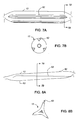
- FIG. 7A is a schematic side view of an inflated balloon with one type of treated region
- FIG. 7B is a schematic end view of an inflated balloon with one type of treated region.
- FIG. 8A is a schematic side view of an inflated balloon with one type of treated region
- FIG. 8B is a schematic end view of an inflated balloon with one type of treated region.
- stent 10 is placed over a balloon 12 carried near a distal end of a catheter 14, and is directed through a lumen 16, e.g., a blood vessel such as the coronary artery, until the portion carrying the balloon and stent reaches the region of an occlusion 18 ( FIG. 1A ).
- the stent 10 is then radially expanded by inflating the balloon 12, and is pressed against the vessel wall with the result that occlusion 18 is compressed, and the vessel wall surrounding it undergoes a radial expansion ( FIG. 1B ).
- the pressure is then released from the balloon and the catheter is withdrawn from the vessel ( FIG. 1C ).
- the balloon is in a folded condition in which the balloon material is arranged into three flaps or lobes 20, 22, 24 and the lobes are wrapped around the catheter body to provide a low profile ( FIG. 2A ).
- inflation fluid is introduced into the balloon and the lobes unwrap such that at full inflation the balloon forms a substantially circular cross section of a diameter sufficient to carry out the desired treatment, such as an angioplasty and/or stent delivery procedure ( FIG. 2B ).
- the inflation fluid is withdrawn from the balloon and the balloon forms three lobes ( FIG. 2C ).
- Forming two or more lobes, such as three, four, five, six, seven or more lobes, on deflation reduces the profile of the balloon which facilitates withdrawal of the balloon by, for example reducing the likelihood of snagging the stent and minimizing friction or abrasion with the body lumen.
- the formation of a desired lobe configuration is facilitated by treating the balloon wall to modify its chemical and/or mechanical properties, such as its stiffness or flexural strength, in different ways in different regions.
- the balloon 12 has two series of modified regions 26, 28 which alternate with one another and with regions of unmodified balloon material.
- the regions 26, 28 have been treated by different processes so that their properties differ from each other.
- the regions 26 have been modified so that, upon balloon deflation, they form the valleys between lobes and the regions 28 form the apexes of the lobes.
- the regions 26, 28 are formed by separate processes of ablating and modifying crystallinity of the balloon material.
- regions 26, 28 of the balloon are exposed to ultraviolet radiation.
- the regions 26 are exposed to an ultraviolet radiation from a laser 30 controlled by a controller 32 to deliver energy to the exposed regions such that the laser fluence exceeds the ablation threshold of the material. Chemical bonds are broken and the material is fractured into energetic fragments which leave the ablation zone. It is theorized that most of the energy is deposited in the ejected material so there is little thermal damage to surrounding materials.
- regions 26 removes some of the thickness of the material and therefore reduces the stiffness of these regions more than regions exposed to lower total energy or the unmodified polymer. As a result, the more flexible regions 26 tend to fold and collapse more quickly as the balloon is deflated, forming valleys.
- the regions 28 are formed by exposure of ultraviolet radiation at a lower fluence, that is below the ablation threshold.
- the regions 28 that are treated with the lower energy have increased crystallinity, which increases the stiffness or modulus of these regions.
- the increased stiffness causes the treated regions to be less flexible than the unmodified regions and thus the balloon is less likely to bend in the stiffer regions than in the unmodified regions.
- the stiffer regions 28 form the apexes of the lobes upon refolding.
- the balloon thus has three regions, where each of the three regions has a different flexibility due to different amount of material thickness or crystallinity in each region.
- Exposure to UV radiation can increase the crystallinity of the polymer and/or ablate or remove polymeric material. If the balloon is ablated, the amount of material removed can be for example, about 0.1 -15%, such as 0.5 to 2.5% of the balloon wall thickness. If the balloon's crystallinity is modified without substantial ablation effects, the crystallinity of the polymer can be increased by about 2 to 90%, e.g., 2-5%, 5-10%, 10-20%, 20-40%, 40-60%, 60-70%, 70-80%. 80-90% or 20-80%, compared to the unmodified polymer. In some embodiments, the crystallinity percentage can be two, three or four times after modification than prior to modification.
- the amount of crystallinity and/or material removal can be selected to finely tailor the balloon refolding properties. Whether material is removed or not is dependent on the fluence of the laser and the material from which the balloon is formed.
- the amount of change in crystallinity can be controlled by controlling the energy delivered to the exposed regions, such as by controlling the time of exposure, the fluence and/or the wavelength of radiation. Crystallinity can be increased by increasing the exposure time at a low fluence.
- a suitable laser is a multigas UV excimer laser at a wavelength of about 193 nm. Ultraviolet ablation is further described in U.S. 4,911,711 . Suitable ablation and control systems are available from Coherent Lambda Physiks, in Goettingen, Germany. Crystallinity can be measured by WAX/SAX x-ray diffraction. Crystallinity measurements can be made at various vendors, such as the University of Minnesota Shepard characterization lab.
- regions 34, 36 can be formed by using different modification techniques.
- the regions 34, 36 are each regions with increased crystallinity, but one region 34 has greater crystallinity than the other region 36.
- the region 34 with the greatest crystallinity forms the apex of the fold when the balloon is collapsed.
- the region 36 with somewhat increased crystallinity that is the region where the crystallinity is greater than the unmodified balloon material but less than the region 34 with the greatest crystallinity, tends to fold into the valleys between the lobes of the collapsed balloon.
- a balloon can be treated with only one treatment method that increases crystallinity without substantially removing material from the surface of the balloon, that is, without ablation.
- the thickness of the balloon in the treated and untreated regions can be substantially the same.
- Crystallinity can be increased by heating the polymer material to between the glass transition temperature and the melt flow temperature. Within this temperature range, crystals begin to form or crystals that were previously present grow larger. Crystallinity can be changed only on the surface or can be changed throughout the depth of the balloon wall.
- Suitable techniques for inputting heat into the balloon affect primarily the surface of the balloon.
- a UV laser may penetrate only part way into a polymer surface, such as 1-60 Angstroms into the balloon.
- Other heating techniques can penetrate more deeply into the material.
- the energy With some methods of applying energy, the energy not only penetrates into the material, but radiates isotropically. This heating is considered to be massive or bulk heating of the material, because more than just the surface of the material is heated.
- a laser such as a CO 2 laser, an IR laser, a YAG laser, a diode laser or any another suitable photon source, a heat stick, i.e., a conductive material connected to a heat cartridge, or an RF generator can be used to apply heat to the balloon.
- a heat stick i.e., a conductive material connected to a heat cartridge
- an RF generator a jelly having metal particles can be applied to the regions to be treated.
- the balloon can be filled with a fluid to absorb the heat and prevent other portions of the balloon from being simultaneously treated.
- the amount of crystallinity can be controlled, such as by controlling the amount of time that energy is input into the balloon or controlling the energy output by the energy input device.
- a mask can be used or the device for applying the heat can be focused only in the region where crystallization is desired.
- the depth of the crystallization can determine whether the treated region ends up on the apex or the valley of a fold.
- Surface treatment with a UV laser tends to form treated regions that are in the valleys of the folds of the balloon, where treatment with a CO 2 laser or hot stick forms treated regions that are on the apex of the folds a balloon.
- Flexibility or stiffness variations can also be formed by other techniques, such as ion beam exposure and mechanically by cutting regions of the balloon wall. All of these techniques can be used in any combination to provide desired properties to the balloon.
- Ion beam treatment is further described in U.S. Application No. 11/533,588, filed September 20, 2006 , and U.S. Application No. 11/355,392, filed February 16, 2006 .
- the treated regions can be formed by application of energy on the balloon directly or on a polymer tubular parison that is subsequently formed or blown into a balloon, e.g. by free inflation or blow molding. Balloon formation is described further in U.S. 4,963,313 .
- Polymers suitable for forming the balloon include biaxially oriented polymers, thermoplastic elastomers, engineering thermoplastic elastomers, polyethylenes, polyethylene terephthalate (PET), polybutylenes, polyamides (e.g. nylon 66), polyether block amides (e.g., PEBAX®), polypropylene (PP), polystyrene (PS), polyvinyl chlorides (PVC), polytetrafluorethylene (PTFE), polymethylmethacrylate (PMMA), polyimide, polycarbonate (PC), polyisoprene rubber (PI), nitrile rubbers, silicone rubbers, ethylene-propylene diene rubbers (EPDM), butyl rubbers (BR), thermoplastic polyurethanes (PU) (e.g., those based on a glycol ether and an isocyanate, such as PELLETHANE®).
- PEBAX® polypropylene
- PS polystyrene
- PVC polyvinyl
- a poly(ether-amide) block copolymer having the general formula in which PA represents a polyamide segment, e.g., nylon 12, and PE represents a polyether segment, e.g., poly(tetramethylene glycol) is utilized.
- PA represents a polyamide segment
- PE represents a polyether segment
- poly(tetramethylene glycol) is utilized.
- Such polymers are commercially available from ARKEMA under the tradename PEBAX®.
- the balloon can be formed of single polymer or of multiple polymers, e.g. by coextrusion.
- the fluence threshold depends on the balloon material and on the type of wavelength of energy input into the material.
- Suitable UV lasers for treating the balloon have a wavelength between about 150-450 nm, such as 157, 193, 248, 308 or 351 nm.
- For treating a PET or a PEBAX® balloon with a 193 nm laser less than about 150 mJ/cm 2 , such as between about 60-70 mJ/cm 2 will avoid ablating the balloon material.
- Other combinations of materials and lasers will have different thresholds of fluence to avoid ablation.
- the treated regions can be arranged in other configurations to enhance refolding.
- the treated regions spiral around the balloon.
- the treated regions are only on the cones, only on the body or both on the body and the cones of the balloon.
- the treated regions are not formed in a contiguous line, but are formed as a series of dots, dashes or shapes which together determine where the balloon will fold upon deflation.
- Balloons can be treated to facilitate formation of two or more, preferably three or four or more lobes.
- the lobes that form when the balloon is deflated after use in a lumen can form at locations corresponding to the locations of the lobes formed and wrapped for delivery or the lobes can form at different locations on deflation.
- the diameter of the collapsed balloon is less than when the balloon flattens or pancakes. This smaller profile can facilitate in removing the collapsed balloon from a lumen, such as a stent or vessel. That is, the folded balloon can be smoothly removed from the lumen with less risk of sticking or catching on the lumen on removal.
- any number of treated regions can be formed on the surface of the balloon, such as four, five, six, seven or eight treated regions.
- the balloons can be used in vascular and nonvascular applications, including coronary, peripheral, carotid, esophageal or uretheral applications.
- the beam from the laser is about 1 mm wide and about 5 mm long.
- Three linear regions approximately 1 mm in width spaced equidistantly about the balloon are exposed.
- the regions are exposed at a shot spacing of 400 microns.
- the exposed regions became opaque and have a crystallinity of about 22%, where the untreated regions has a crystallinity of about 16%.
- an effect of some heat applications is to rearrange material at the surface of the balloon.
- a magnified view of a balloon surface that is crystallized using a UV laser shows nodules 52.
- the balloon is a TAXUS® Liberté TM OTW (PEBAX® 7233) polymer balloon available from Boston Scientific, Natick, MA, and is exposed to UV radiation using a Lambda 210i, multigas UV excimer laser (available from Coherent Lambda Physiks, in Goettingen, Germany) operating at a wavelength of 193 nm with an attenuator set at 30 VA to achieve an output of 30 mJ/cm 2 .
- Forming the nodules 52 does not remove polymer material from the balloon wall, but rearranges the material on the balloon surface and can reduce the effective wall thickness between the nodules.
- a non-treated balloon wall would appear smooth and free of nodules.
- Nodules 52 are observed when the balloon is treated with a UV laser, but are hot observed with other treatments, such as CO2 laser or hot stick.
- the UV laser treated regions also appear to be opaque, due to the surface modification.
- a treated balloon has three stripes 62 made using UV laser. All stripes extend past the balloon body-cone transition area on both the distal and proximal ends. Each stripe has 1 mm width.
- FIG. 7B the end view shows the three treated regions on the cone of the balloon.
- the folded balloon forms three lobes.
- the profile of the tri-folded balloon is about 30% less than when compared to a pancaked balloon, or a balloon that has not been treated and flattens rather than folds when deflated.
- TAXUS(R) Liberte(TM) OTW balloon is treated in regions to enhance refolding, the refolding profile was found to be 2.85 mm.
Abstract
Description
- This invention relates to medical balloon deflation.
- The body includes various passageways such as arteries, other blood vessels, and other body lumens. These passageways sometimes become occluded, e.g., by a tumor or restricted by plaque. To widen an occluded body vessel, balloon catheters can be used, e.g., in angioplasty.
- A balloon catheter can include an inflatable and deflatable balloon carried by a long and narrow catheter body. The balloon is initially folded around the catheter body to reduce the radial profile of the balloon catheter for easy insertion into the body.
-
US 2005/0146085 A1 discloses a medical device balloon from a tubular parison by a process which established a controlled location (initiation zone) on the parison where the radial expansion is initiated. The initiation within the initiation zone is achieved by heating the parison in that location to a higher temperature that the remainder of the parison for at least a portion of the blowing time. -
EP 0 783 897 A2 discloses a dilatation balloon made according to a process that yields high hoop strength and uniformity in balloon wall thickness. The dilatation balloon walls are thinned primarily along tapered sections between proximal and distal balloon stents and a medial working section of the balloon. -
WO 2006/65356 A1 -
US 2006/182873 discloses a method of making a medical balloon. - During use, the folded balloon can be delivered to a target location in the vessel, e.g., a portion occluded by plaque, by threading the balloon catheter over a guide wire emplaced in the vessel. The balloon is then inflated, e.g., by introducing a fluid into the interior of the balloon. Inflating the balloon can radially expand the vessel so that the vessel can permit an increased rate of blood flow. After use, the balloon is deflated and withdrawn from the body. It is desirable that upon deflation, the balloon forms a predictable low profile configuration that facilitates withdrawal from the body.
- The problem of the invention is to provide a method of making an inflatable medical balloon which forms a predictable low profile configuration that facilitates withdrawal form the body. The problem is solved by a method according to claim 1.
- In an aspect, a method of making an inflatable medical balloon is described. The method includes providing a generally cylindrical inflatable balloon wall or balloon parison formed of polymer, forming a series of first ablated regions wherein the polymer is removed to enhance flexibility of the wall, forming a series of second treated regions alternating with the first ablated regions, the second treated regions being formed by UV radiation exposure, heating, or ion implantation, such that the second treated regions have less flexibility than the first ablated regions.
- In another aspect, a method of making an inflatable medical balloon is described. The method includes providing a generally cylindrical inflatable balloon wall or balloon parison formed of polymer and forming a series of first treated regions where the polymer crystallinity is increased, but no polymer is removed from the balloon in the first treated regions, wherein upon deflation the balloon folds according to the locations of the series of first treated regions.
- In another aspect, an inflatable medical balloon device is described. The device includes a generally cylindrical balloon wall formed of polymer. The wall includes a series of first ablated regions where polymer has been removed to enhance flexibility and a series of second treated regions alternating with the ablated regions, and third regions. The second treated regions having a flexibility less than the ablated regions but more flexibility than the third regions of the balloon.
- In an aspect, a medical device including an inflatable balloon having a generally cylindrical wall formed of polymer is described. The wall includes a series of first treated regions where the crystallinity of the polymer is greater compared to the crystallinity of the polymer in a series of second regions formed of the polymer, the first treated regions having a flexibility different than the second regions, wherein the balloon device upon deflation folds according to the locations of the first treated locations.
- In an aspect, a medical device including an inflatable balloon having a generally cylindrical wall formed of polymer is described. The wall includes a series of ablated groove regions. The groove regions have grooves with a depth of between about 1-2% of a thickness of the wall and the grooves regions have at least about 4% greater polymer crystallinity than polymer regions outside the grooved regions.
- In an aspect, the invention features a method including providing a medical device as described herein, arranging the balloon into lobes and wrapping the lobes, delivering the balloon into the body, inflating the balloon, and deflating the balloon, whereby the balloon forms at least three lobes.
- In an aspect, a medical device including an inflatable balloon having a generally cylindrical wall formed of polymer is described. The wall has a series of ablated groove regions, the groove regions having grooves with a depth of between about 1-2% of a thickness of the wall and the grooves regions having at least about 4% greater polymer crystallinity than polymer regions outside the grooved regions.
- In an aspect, a medical device including an inflatable balloon having a generally cylindrical wall formed of polymer is described. The wall has a series of regions having at least about 4% greater polymer crystallinity than polymer areas outside the regions, wherein the surface of the balloon in the regions has raised nodules of polymer that cause the polymer areas outside the regions to have a greater effective thickness than the regions.
- Embodiments may include one or more of the following advantages. A balloon can be formed that folds after inflation into a desired configuration which has a low profile that facilitates withdrawal from the vessel after angioplasty and/or stent delivery. Balloons treated using two or more different processes can enhance the precision and reliability of balloon folding. The processes can be used to define regions of different flexibility in a desired pattern to induce a desired fold profile. The different processes can employ different techniques such as laser ablation, hot stick, CO2 laser, and ion beam treatment which can induce different effects to the balloon material, such as material removal, cross-linking, and carbonization.
- Still further aspects, features and advantages follow.
-
FIGS. 1A - 1C are partial cross-sectional views illustrating delivery of a stent in a collapsed state over a balloon, expansion of the stent by inflation of the balloon, and deflation and withdrawal of the balloon; -
FIGS. 2A -2C are end on cross-sectional views of a balloon in conditions corresponding toFIGS. 1A -1C . -
FIG. 3A is a side view of a balloon in an inflated state; -
FIG. 3B is a cross-sectional view through the wall of the balloon inFIG. 3A ; -
FIG. 3C is a cross-sectional view similar toFIG. 3B with the balloon in a refolded deflated state. -
FIG. 4A is a schematic of the balloon during a first treatment process; -
FIG. 4B is a schematic of the balloon inFIG. 4A undergoing a second treatment process. -
FIG. 5A is a schematic of the balloon treated with first and second treatment processes; -
FIG. 5B is a schematic of the balloon a folded state. -
FIG. 6 is a scanning electron microscope image of a modified surface. -
FIG. 7A is a schematic side view of an inflated balloon with one type of treated region; -
FIG. 7B is a schematic end view of an inflated balloon with one type of treated region. -
FIG. 8A is a schematic side view of an inflated balloon with one type of treated region; -
FIG. 8B is a schematic end view of an inflated balloon with one type of treated region. - Like reference symbols in the various drawings indicate like elements.
- Referring to
FIGS. 1A-1C ,stent 10 is placed over aballoon 12 carried near a distal end of acatheter 14, and is directed through alumen 16, e.g., a blood vessel such as the coronary artery, until the portion carrying the balloon and stent reaches the region of an occlusion 18 (FIG. 1A ). Thestent 10 is then radially expanded by inflating theballoon 12, and is pressed against the vessel wall with the result thatocclusion 18 is compressed, and the vessel wall surrounding it undergoes a radial expansion (FIG. 1B ). The pressure is then released from the balloon and the catheter is withdrawn from the vessel (FIG. 1C ). - Referring as well to
FIGS. 2A-2C , during delivery to the treatment site, the balloon is in a folded condition in which the balloon material is arranged into three flaps orlobes FIG. 2A ). During inflation, inflation fluid is introduced into the balloon and the lobes unwrap such that at full inflation the balloon forms a substantially circular cross section of a diameter sufficient to carry out the desired treatment, such as an angioplasty and/or stent delivery procedure (FIG. 2B ). After full expansion, the inflation fluid is withdrawn from the balloon and the balloon forms three lobes (FIG. 2C ). Forming two or more lobes, such as three, four, five, six, seven or more lobes, on deflation reduces the profile of the balloon which facilitates withdrawal of the balloon by, for example reducing the likelihood of snagging the stent and minimizing friction or abrasion with the body lumen. - Referring as well to
FIGS. 3A-3C , the formation of a desired lobe configuration is facilitated by treating the balloon wall to modify its chemical and/or mechanical properties, such as its stiffness or flexural strength, in different ways in different regions. Referring particularly toFIGS. 3A and 3B , theballoon 12 has two series of modifiedregions regions FIG. 3C , in the embodiment illustrated, theregions 26 have been modified so that, upon balloon deflation, they form the valleys between lobes and theregions 28 form the apexes of the lobes. - Referring to
FIGS. 4A and 4B , theregions regions FIG. 4A , theregions 26 are exposed to an ultraviolet radiation from alaser 30 controlled by acontroller 32 to deliver energy to the exposed regions such that the laser fluence exceeds the ablation threshold of the material. Chemical bonds are broken and the material is fractured into energetic fragments which leave the ablation zone. It is theorized that most of the energy is deposited in the ejected material so there is little thermal damage to surrounding materials. The high energy input toregions 26 removes some of the thickness of the material and therefore reduces the stiffness of these regions more than regions exposed to lower total energy or the unmodified polymer. As a result, the moreflexible regions 26 tend to fold and collapse more quickly as the balloon is deflated, forming valleys. Referring toFIG. 4B , theregions 28 are formed by exposure of ultraviolet radiation at a lower fluence, that is below the ablation threshold. Theregions 28 that are treated with the lower energy have increased crystallinity, which increases the stiffness or modulus of these regions. The increased stiffness causes the treated regions to be less flexible than the unmodified regions and thus the balloon is less likely to bend in the stiffer regions than in the unmodified regions. Thestiffer regions 28 form the apexes of the lobes upon refolding. The balloon thus has three regions, where each of the three regions has a different flexibility due to different amount of material thickness or crystallinity in each region. - Exposure to UV radiation can increase the crystallinity of the polymer and/or ablate or remove polymeric material. If the balloon is ablated, the amount of material removed can be for example, about 0.1 -15%, such as 0.5 to 2.5% of the balloon wall thickness. If the balloon's crystallinity is modified without substantial ablation effects, the crystallinity of the polymer can be increased by about 2 to 90%, e.g., 2-5%, 5-10%, 10-20%, 20-40%, 40-60%, 60-70%, 70-80%. 80-90% or 20-80%, compared to the unmodified polymer. In some embodiments, the crystallinity percentage can be two, three or four times after modification than prior to modification. The amount of crystallinity and/or material removal can be selected to finely tailor the balloon refolding properties. Whether material is removed or not is dependent on the fluence of the laser and the material from which the balloon is formed. The amount of change in crystallinity can be controlled by controlling the energy delivered to the exposed regions, such as by controlling the time of exposure, the fluence and/or the wavelength of radiation. Crystallinity can be increased by increasing the exposure time at a low fluence. A suitable laser is a multigas UV excimer laser at a wavelength of about 193 nm. Ultraviolet ablation is further described in
U.S. 4,911,711 . Suitable ablation and control systems are available from Coherent Lambda Physiks, in Goettingen, Germany. Crystallinity can be measured by WAX/SAX x-ray diffraction. Crystallinity measurements can be made at various vendors, such as the University of Minnesota Shepard characterization lab. - Referring as well to
FIGS. 5A and 5B , inother examples regions regions region 34 has greater crystallinity than theother region 36. Theregion 34 with the greatest crystallinity forms the apex of the fold when the balloon is collapsed. Theregion 36 with somewhat increased crystallinity, that is the region where the crystallinity is greater than the unmodified balloon material but less than theregion 34 with the greatest crystallinity, tends to fold into the valleys between the lobes of the collapsed balloon. - As an alternative to treating the balloon with two different treatment methods, a balloon can be treated with only one treatment method that increases crystallinity without substantially removing material from the surface of the balloon, that is, without ablation. The thickness of the balloon in the treated and untreated regions can be substantially the same. Crystallinity can be increased by heating the polymer material to between the glass transition temperature and the melt flow temperature. Within this temperature range, crystals begin to form or crystals that were previously present grow larger. Crystallinity can be changed only on the surface or can be changed throughout the depth of the balloon wall.
- Suitable techniques for inputting heat into the balloon, such as UV lasers, affect primarily the surface of the balloon. For example, a UV laser may penetrate only part way into a polymer surface, such as 1-60 Angstroms into the balloon. Other heating techniques can penetrate more deeply into the material. With some methods of applying energy, the energy not only penetrates into the material, but radiates isotropically. This heating is considered to be massive or bulk heating of the material, because more than just the surface of the material is heated. A laser, such as a CO2 laser, an IR laser, a YAG laser, a diode laser or any another suitable photon source, a heat stick, i.e., a conductive material connected to a heat cartridge, or an RF generator can be used to apply heat to the balloon. In the case of an RF generator, a jelly having metal particles can be applied to the regions to be treated. If a laser is used to apply heat to the balloon, the balloon can be filled with a fluid to absorb the heat and prevent other portions of the balloon from being simultaneously treated. As noted herein, the amount of crystallinity can be controlled, such as by controlling the amount of time that energy is input into the balloon or controlling the energy output by the energy input device. To focus the heat on particular regions of the balloon, a mask can be used or the device for applying the heat can be focused only in the region where crystallization is desired. With some methods of treating the balloon, the depth of the crystallization can determine whether the treated region ends up on the apex or the valley of a fold. Surface treatment with a UV laser tends to form treated regions that are in the valleys of the folds of the balloon, where treatment with a CO2 laser or hot stick forms treated regions that are on the apex of the folds a balloon.
- Flexibility or stiffness variations can also be formed by other techniques, such as ion beam exposure and mechanically by cutting regions of the balloon wall. All of these techniques can be used in any combination to provide desired properties to the balloon. Ion beam treatment is further described in
U.S. Application No. 11/533,588, filed September 20, 2006 U.S. Application No. 11/355,392, filed February 16, 2006 U.S. 4,963,313 . - Polymers suitable for forming the balloon include biaxially oriented polymers, thermoplastic elastomers, engineering thermoplastic elastomers, polyethylenes, polyethylene terephthalate (PET), polybutylenes, polyamides (e.g. nylon 66), polyether block amides (e.g., PEBAX®), polypropylene (PP), polystyrene (PS), polyvinyl chlorides (PVC), polytetrafluorethylene (PTFE), polymethylmethacrylate (PMMA), polyimide, polycarbonate (PC), polyisoprene rubber (PI), nitrile rubbers, silicone rubbers, ethylene-propylene diene rubbers (EPDM), butyl rubbers (BR), thermoplastic polyurethanes (PU) (e.g., those based on a glycol ether and an isocyanate, such as PELLETHANE®). In particular embodiments, a poly(ether-amide) block copolymer having the general formula

nylon 12, and PE represents a polyether segment, e.g., poly(tetramethylene glycol) is utilized. Such polymers are commercially available from ARKEMA under the tradename PEBAX®. The balloon can be formed of single polymer or of multiple polymers, e.g. by coextrusion. - As noted above, the fluence threshold depends on the balloon material and on the type of wavelength of energy input into the material. Suitable UV lasers for treating the balloon have a wavelength between about 150-450 nm, such as 157, 193, 248, 308 or 351 nm. For treating a PET or a PEBAX® balloon with a 193 nm laser, less than about 150 mJ/cm2 , such as between about 60-70 mJ/cm2 will avoid ablating the balloon material. Other combinations of materials and lasers will have different thresholds of fluence to avoid ablation.
- In addition to the linear treated regions described, the treated regions can be arranged in other configurations to enhance refolding. In some embodiments, the treated regions spiral around the balloon. In some embodiments the treated regions are only on the cones, only on the body or both on the body and the cones of the balloon. In yet other embodiments the treated regions are not formed in a contiguous line, but are formed as a series of dots, dashes or shapes which together determine where the balloon will fold upon deflation.
- Balloons can be treated to facilitate formation of two or more, preferably three or four or more lobes. The lobes that form when the balloon is deflated after use in a lumen can form at locations corresponding to the locations of the lobes formed and wrapped for delivery or the lobes can form at different locations on deflation. When the balloon is able to collapse into a multilobed profile, the diameter of the collapsed balloon is less than when the balloon flattens or pancakes. This smaller profile can facilitate in removing the collapsed balloon from a lumen, such as a stent or vessel. That is, the folded balloon can be smoothly removed from the lumen with less risk of sticking or catching on the lumen on removal. Any number of treated regions can be formed on the surface of the balloon, such as four, five, six, seven or eight treated regions. The balloons can be used in vascular and nonvascular applications, including coronary, peripheral, carotid, esophageal or uretheral applications.
- A 3.0x16 mm TAXUS® Liberté™ OTW (PEBAX® 7233) polymer balloon available from Boston Scientific, Natick, MA, is inflated to a pressure of 2 psi and exposed to UV radiation using a Lambda 210i, multigas UV excimer laser (available from Coherent Lambda Physiks, in Goettingen, Germany) operating at a pulse duration of 29 ns and at a wavelength of 193 nm with an attenuator set at 30 VA to deliver a fluence of 30 mJ/cm2, which is below the ablation threshold of PEBAX®, which is around 60-70 mJ/cm2. The beam from the laser is about 1 mm wide and about 5 mm long. Three linear regions approximately 1 mm in width spaced equidistantly about the balloon are exposed. The regions are exposed at a shot spacing of 400 microns. The exposed regions became opaque and have a crystallinity of about 22%, where the untreated regions has a crystallinity of about 16%.
- Referring to
FIG. 6 , an effect of some heat applications, such as application of UV laser, is to rearrange material at the surface of the balloon. A magnified view of a balloon surface that is crystallized using a UV laser showsnodules 52. The balloon is a TAXUS® Liberté™ OTW (PEBAX® 7233) polymer balloon available from Boston Scientific, Natick, MA, and is exposed to UV radiation using a Lambda 210i, multigas UV excimer laser (available from Coherent Lambda Physiks, in Goettingen, Germany) operating at a wavelength of 193 nm with an attenuator set at 30 VA to achieve an output of 30 mJ/cm2. Forming thenodules 52 does not remove polymer material from the balloon wall, but rearranges the material on the balloon surface and can reduce the effective wall thickness between the nodules. A non-treated balloon wall would appear smooth and free of nodules.Nodules 52 are observed when the balloon is treated with a UV laser, but are hot observed with other treatments, such as CO2 laser or hot stick. The UV laser treated regions also appear to be opaque, due to the surface modification.
Referring toFIG. 7 A , a treated balloon has threestripes 62 made using UV laser. All stripes extend past the balloon body-cone transition area on both the distal and proximal ends. Each stripe has 1 mm width. Referring toFIG. 7B , the end view shows the three treated regions on the cone of the balloon. Referring toFIGS. 8A and 8B , the folded balloon forms three lobes. The profile of the tri-folded balloon is about 30% less than when compared to a pancaked balloon, or a balloon that has not been treated and flattens rather than folds when deflated. When a 3.0 x 16 mm TAXUS(R) Liberte(TM) OTW balloon is treated in regions to enhance refolding, the refolding profile was found to be 2.85 mm. A similar balloon that is not treated pancakes to have a profile of 4.16 mm.
Claims (7)
- A method of making an inflatable medical balloon (12) forming two or more lobes on deflation, which method comprises
providing a generally tubular inflatable balloon (12) or balloon parison formed of polymer,
forming a series of first series regions (26) wherein polymer is removed to enhance flexibility, and
forming a series of second treated regions (28) by UV radiation exposure, heating, or ion implantation, such that the second treated regions have less flexibility than the first treated regions, wherein the first treated regions (26) and second treated regions (28) alternate radially about the balloon (12) and the first treated regions and the second treated regions alternate with untreated regions radially about the balloon, such that,
upon balloon deflation, the first series regions (26) form valleys between lobes and the second treated regions (28) form apexes of the lobes, characterized by forming the second treated regions includes increasing the crystallinity in the second treated regions without substantially removing polymer. - The method of claim 1 comprising forming the first treated regions (26) and second treated regions (28) by exposure to UV radiation.
- The method of claim 2 comprising controlling the laser fluence to ablate polymer in the first regions (26) and to increase the polymer crystallinity in the second treated regions (28).
- The method of claim 1 comprising forming the second treated regions (28) by heating.
- The method of claim 4 comprising heating by exposure to infrared radiation.
- The method of claim 5 comprising heating by direct exposure to a heat source.
- The method of claim 1 comprising forming said second treated regions by ion beam exposure.
Applications Claiming Priority (2)
| Application Number | Priority Date | Filing Date | Title |
|---|---|---|---|
| US11/599,049 US8845581B2 (en) | 2006-11-14 | 2006-11-14 | Medical balloon deflation |
| PCT/US2007/078671 WO2008060750A2 (en) | 2006-11-14 | 2007-09-17 | Medical balloon deflation |
Publications (2)
| Publication Number | Publication Date |
|---|---|
| EP2089087A2 EP2089087A2 (en) | 2009-08-19 |
| EP2089087B1 true EP2089087B1 (en) | 2012-03-28 |
Family
ID=39345319
Family Applications (1)
| Application Number | Title | Priority Date | Filing Date |
|---|---|---|---|
| EP07842621A Not-in-force EP2089087B1 (en) | 2006-11-14 | 2007-09-17 | Medical balloon deflation |
Country Status (6)
| Country | Link |
|---|---|
| US (1) | US8845581B2 (en) |
| EP (1) | EP2089087B1 (en) |
| JP (1) | JP5466008B2 (en) |
| AT (1) | ATE551093T1 (en) |
| CA (1) | CA2669605C (en) |
| WO (1) | WO2008060750A2 (en) |
Families Citing this family (19)
| Publication number | Priority date | Publication date | Assignee | Title |
|---|---|---|---|---|
| US8153181B2 (en) | 2006-11-14 | 2012-04-10 | Boston Scientific Scimed, Inc. | Medical devices and related methods |
| EP2072067A1 (en) * | 2007-12-21 | 2009-06-24 | Abbott Laboratories Vascular Enterprises Limited | Lamellar shaped layers in medical devices |
| DE102008008925A1 (en) * | 2008-02-13 | 2009-08-20 | Biotronik Vi Patent Ag | Catheter, intraluminal endoprosthesis delivery system, and method of making the same |
| DE102008008926A1 (en) * | 2008-02-13 | 2009-08-20 | Biotronik Vi Patent Ag | System for introducing an intraluminal endoprosthesis and method of making such a system |
| EP2299945B1 (en) | 2008-06-05 | 2016-03-23 | Boston Scientific Scimed, Inc. | Balloon bifurcated lumen treatment |
| WO2009149410A1 (en) * | 2008-06-05 | 2009-12-10 | Boston Scientific Scimed, Inc. | Deflatable bifurcated device |
| WO2010065265A2 (en) * | 2008-11-25 | 2010-06-10 | Edwards Lifesciences Corporation | Apparatus and method for in situ expansion of prosthetic device |
| US8864786B2 (en) * | 2009-04-09 | 2014-10-21 | Medtronic Vascular, Inc. | Dual-layer medical balloon and process of making |
| AU2010302988B2 (en) * | 2009-09-30 | 2015-01-15 | Sanofi-Aventis Deutschland Gmbh | Method for treating a plastic part, method for manufacturing a drug delivery device and drug delivery device |
| US9364637B2 (en) * | 2011-09-06 | 2016-06-14 | Medtronic, Inc. | Transcatheter balloon-assisted mitral valve navigation device and method |
| WO2013134437A1 (en) * | 2012-03-06 | 2013-09-12 | Futurematrix Interventional, Inc. | Medical balloon with enhanced refolding properties |
| JP6184070B2 (en) * | 2012-09-19 | 2017-08-23 | 株式会社カネカ | Method for manufacturing balloon for balloon catheter |
| JP6259560B2 (en) * | 2012-09-19 | 2018-01-10 | 株式会社カネカ | Balloon for balloon catheter |
| JP6204483B2 (en) * | 2012-11-02 | 2017-09-27 | べシックス・バスキュラー・インコーポレイテッド | Balloon assembly |
| US20140213970A1 (en) * | 2013-01-28 | 2014-07-31 | Edwards Lifesciences Corporation | Catheter balloon and method of fabrication |
| US10201683B2 (en) * | 2014-06-17 | 2019-02-12 | Covidien Lp | Medical balloon including pleats |
| US10414913B2 (en) | 2016-04-11 | 2019-09-17 | International Business Machines Corporation | Articles of manufacture including macromolecular block copolymers |
| US9828456B2 (en) | 2016-04-11 | 2017-11-28 | International Business Machines Corporation | Macromolecular block copolymers |
| US9834637B2 (en) | 2016-04-11 | 2017-12-05 | International Business Machines Corporation | Macromolecular block copolymer formation |
Citations (2)
| Publication number | Priority date | Publication date | Assignee | Title |
|---|---|---|---|---|
| US5501759A (en) * | 1991-11-29 | 1996-03-26 | Schneider (Usa) Inc. | Laser bonding of angioplasty balloon catheters |
| US6585926B1 (en) * | 2000-08-31 | 2003-07-01 | Advanced Cardiovascular Systems, Inc. | Method of manufacturing a porous balloon |
Family Cites Families (32)
| Publication number | Priority date | Publication date | Assignee | Title |
|---|---|---|---|---|
| US4941877A (en) * | 1989-01-26 | 1990-07-17 | Cordis Corporation | Balloon catheter |
| US5352199A (en) * | 1993-05-28 | 1994-10-04 | Numed, Inc. | Balloon catheter |
| US5746745A (en) * | 1993-08-23 | 1998-05-05 | Boston Scientific Corporation | Balloon catheter |
| US5545132A (en) * | 1993-12-21 | 1996-08-13 | C. R. Bard, Inc. | Helically grooved balloon for dilatation catheter and method of using |
| NL1000106C2 (en) * | 1995-04-10 | 1996-10-11 | Cordis Europ | Balloon balloon balloon catheter and method of making the balloon. |
| US5733301A (en) | 1996-01-11 | 1998-03-31 | Schneider (Usa) Inc. | Laser ablation of angioplasty catheters and balloons |
| US5853389A (en) * | 1996-03-07 | 1998-12-29 | Cordis Corporation | Balloon catheter and method for manufacturing |
| US5810867A (en) * | 1997-04-28 | 1998-09-22 | Medtronic, Inc. | Dilatation catheter with varied stiffness |
| US6030369A (en) * | 1997-07-03 | 2000-02-29 | Target Therapeutics Inc. | Micro catheter shaft |
| US6242063B1 (en) * | 1997-09-10 | 2001-06-05 | Scimed Life Systems, Inc. | Balloons made from liquid crystal polymer blends |
| US6296655B1 (en) * | 1998-04-27 | 2001-10-02 | Advanced Cardiovascular Systems, Inc. | Catheter balloon with biased multiple wings |
| US6193738B1 (en) * | 1998-05-11 | 2001-02-27 | Scimed Life Systems, Inc. | Balloon cones and waists thinning methodology |
| US6613066B1 (en) | 1998-10-05 | 2003-09-02 | Kaneka Corporation | Balloon catheter and production method therefor |
| US6592550B1 (en) * | 1999-09-17 | 2003-07-15 | Cook Incorporated | Medical device including improved expandable balloon |
| US6702802B1 (en) * | 1999-11-10 | 2004-03-09 | Endovascular Technologies, Inc. | Catheters with improved transition |
| US6544224B1 (en) * | 2000-05-05 | 2003-04-08 | Advanced Cardiovascular Systems, Inc. | Lobed balloon catheter and method of use |
| JP4538918B2 (en) * | 2000-08-02 | 2010-09-08 | 株式会社カネカ | Medical catheter for treating part of a body tube with ionizing radiation |
| US7004963B2 (en) * | 2001-09-14 | 2006-02-28 | Scimed Life Systems, Inc. | Conformable balloons |
| US20030144683A1 (en) * | 2001-12-13 | 2003-07-31 | Avantec Vascular Corporation | Inflatable members having concentrated force regions |
| US7985234B2 (en) * | 2002-02-27 | 2011-07-26 | Boston Scientific Scimed, Inc. | Medical device |
| US6989025B2 (en) * | 2002-10-04 | 2006-01-24 | Boston Scientific Scimed, Inc. | Extruded tubing with discontinuous striping |
| US7306616B2 (en) * | 2003-05-05 | 2007-12-11 | Boston Scientific Scimed, Inc. | Balloon catheter and method of making same |
| US8025637B2 (en) * | 2003-07-18 | 2011-09-27 | Boston Scientific Scimed, Inc. | Medical balloons and processes for preparing same |
| US7604621B2 (en) * | 2003-07-30 | 2009-10-20 | Boston Scientific Scimed, Inc. | Bifurcated stent delivery system |
| US7264458B2 (en) * | 2004-01-07 | 2007-09-04 | Boston Scientific Scimed, Inc. | Process and apparatus for forming medical device balloons |
| US20050177130A1 (en) * | 2004-02-10 | 2005-08-11 | Angioscore, Inc. | Balloon catheter with spiral folds |
| US7713233B2 (en) * | 2004-04-12 | 2010-05-11 | Boston Scientific Scimed, Inc. | Balloons having a crosslinkable layer |
| US8550985B2 (en) | 2004-12-14 | 2013-10-08 | Boston Scientific Scimed, Inc. | Applications of LIPSS in polymer medical devices |
| US8202245B2 (en) * | 2005-01-26 | 2012-06-19 | Boston Scientific Scimed, Inc. | Medical devices and methods of making the same |
| US20060182873A1 (en) * | 2005-02-17 | 2006-08-17 | Klisch Leo M | Medical devices |
| US20070244501A1 (en) * | 2006-04-18 | 2007-10-18 | Horn Daniel J | Medical balloons |
| US7963942B2 (en) * | 2006-09-20 | 2011-06-21 | Boston Scientific Scimed, Inc. | Medical balloons with modified surfaces |
-
2006
- 2006-11-14 US US11/599,049 patent/US8845581B2/en active Active
-
2007
- 2007-09-17 AT AT07842621T patent/ATE551093T1/en active
- 2007-09-17 CA CA2669605A patent/CA2669605C/en not_active Expired - Fee Related
- 2007-09-17 WO PCT/US2007/078671 patent/WO2008060750A2/en active Application Filing
- 2007-09-17 JP JP2009537249A patent/JP5466008B2/en active Active
- 2007-09-17 EP EP07842621A patent/EP2089087B1/en not_active Not-in-force
Patent Citations (2)
| Publication number | Priority date | Publication date | Assignee | Title |
|---|---|---|---|---|
| US5501759A (en) * | 1991-11-29 | 1996-03-26 | Schneider (Usa) Inc. | Laser bonding of angioplasty balloon catheters |
| US6585926B1 (en) * | 2000-08-31 | 2003-07-01 | Advanced Cardiovascular Systems, Inc. | Method of manufacturing a porous balloon |
Also Published As
| Publication number | Publication date |
|---|---|
| US8845581B2 (en) | 2014-09-30 |
| CA2669605C (en) | 2015-02-24 |
| CA2669605A1 (en) | 2008-05-22 |
| WO2008060750A3 (en) | 2008-10-16 |
| JP5466008B2 (en) | 2014-04-09 |
| EP2089087A2 (en) | 2009-08-19 |
| WO2008060750A2 (en) | 2008-05-22 |
| ATE551093T1 (en) | 2012-04-15 |
| US20080114294A1 (en) | 2008-05-15 |
| JP2010509028A (en) | 2010-03-25 |
Similar Documents
| Publication | Publication Date | Title |
|---|---|---|
| EP2089087B1 (en) | Medical balloon deflation | |
| US20210186555A1 (en) | Balloon assemblies having controllably variable topographies | |
| EP1848487B1 (en) | Medical devices | |
| EP1890737B1 (en) | Medical devices with textured surfaces and methods of making the same | |
| US20070299392A1 (en) | Material Delivery System | |
| US7691082B2 (en) | Medical devices | |
| MXPA97000334A (en) | Laser ablation of angioplas catheters and balls | |
| JPH04501670A (en) | Intraluminal sealing with biodegradable polymeric materials | |
| US8827954B2 (en) | Deflatable bifurcated device | |
| US8404165B2 (en) | Catheter distal tip design and method of making |
Legal Events
| Date | Code | Title | Description |
|---|---|---|---|
| PUAI | Public reference made under article 153(3) epc to a published international application that has entered the european phase |
Free format text: ORIGINAL CODE: 0009012 |
|
| 17P | Request for examination filed |
Effective date: 20090606 |
|
| AK | Designated contracting states |
Kind code of ref document: A2 Designated state(s): AT BE BG CH CY CZ DE DK EE ES FI FR GB GR HU IE IS IT LI LT LU LV MC MT NL PL PT RO SE SI SK TR |
|
| 17Q | First examination report despatched |
Effective date: 20090915 |
|
| DAX | Request for extension of the european patent (deleted) | ||
| R17C | First examination report despatched (corrected) |
Effective date: 20100408 |
|
| GRAP | Despatch of communication of intention to grant a patent |
Free format text: ORIGINAL CODE: EPIDOSNIGR1 |
|
| GRAS | Grant fee paid |
Free format text: ORIGINAL CODE: EPIDOSNIGR3 |
|
| GRAA | (expected) grant |
Free format text: ORIGINAL CODE: 0009210 |
|
| AK | Designated contracting states |
Kind code of ref document: B1 Designated state(s): AT BE BG CH CY CZ DE DK EE ES FI FR GB GR HU IE IS IT LI LT LU LV MC MT NL PL PT RO SE SI SK TR |
|
| REG | Reference to a national code |
Ref country code: GB Ref legal event code: FG4D |
|
| REG | Reference to a national code |
Ref country code: CH Ref legal event code: EP |
|
| REG | Reference to a national code |
Ref country code: AT Ref legal event code: REF Ref document number: 551093 Country of ref document: AT Kind code of ref document: T Effective date: 20120415 |
|
| REG | Reference to a national code |
Ref country code: IE Ref legal event code: FG4D |
|
| REG | Reference to a national code |
Ref country code: DE Ref legal event code: R096 Ref document number: 602007021676 Country of ref document: DE Effective date: 20120524 |
|
| REG | Reference to a national code |
Ref country code: NL Ref legal event code: VDEP Effective date: 20120328 |
|
| PG25 | Lapsed in a contracting state [announced via postgrant information from national office to epo] |
Ref country code: LT Free format text: LAPSE BECAUSE OF FAILURE TO SUBMIT A TRANSLATION OF THE DESCRIPTION OR TO PAY THE FEE WITHIN THE PRESCRIBED TIME-LIMIT Effective date: 20120328 |
|
| LTIE | Lt: invalidation of european patent or patent extension |
Effective date: 20120328 |
|
| PG25 | Lapsed in a contracting state [announced via postgrant information from national office to epo] |
Ref country code: GR Free format text: LAPSE BECAUSE OF FAILURE TO SUBMIT A TRANSLATION OF THE DESCRIPTION OR TO PAY THE FEE WITHIN THE PRESCRIBED TIME-LIMIT Effective date: 20120629 Ref country code: LV Free format text: LAPSE BECAUSE OF FAILURE TO SUBMIT A TRANSLATION OF THE DESCRIPTION OR TO PAY THE FEE WITHIN THE PRESCRIBED TIME-LIMIT Effective date: 20120328 Ref country code: FI Free format text: LAPSE BECAUSE OF FAILURE TO SUBMIT A TRANSLATION OF THE DESCRIPTION OR TO PAY THE FEE WITHIN THE PRESCRIBED TIME-LIMIT Effective date: 20120328 |
|
| REG | Reference to a national code |
Ref country code: AT Ref legal event code: MK05 Ref document number: 551093 Country of ref document: AT Kind code of ref document: T Effective date: 20120328 |
|
| PG25 | Lapsed in a contracting state [announced via postgrant information from national office to epo] |
Ref country code: CY Free format text: LAPSE BECAUSE OF FAILURE TO SUBMIT A TRANSLATION OF THE DESCRIPTION OR TO PAY THE FEE WITHIN THE PRESCRIBED TIME-LIMIT Effective date: 20120328 |
|
| PG25 | Lapsed in a contracting state [announced via postgrant information from national office to epo] |
Ref country code: CZ Free format text: LAPSE BECAUSE OF FAILURE TO SUBMIT A TRANSLATION OF THE DESCRIPTION OR TO PAY THE FEE WITHIN THE PRESCRIBED TIME-LIMIT Effective date: 20120328 Ref country code: BE Free format text: LAPSE BECAUSE OF FAILURE TO SUBMIT A TRANSLATION OF THE DESCRIPTION OR TO PAY THE FEE WITHIN THE PRESCRIBED TIME-LIMIT Effective date: 20120328 Ref country code: RO Free format text: LAPSE BECAUSE OF FAILURE TO SUBMIT A TRANSLATION OF THE DESCRIPTION OR TO PAY THE FEE WITHIN THE PRESCRIBED TIME-LIMIT Effective date: 20120328 Ref country code: IS Free format text: LAPSE BECAUSE OF FAILURE TO SUBMIT A TRANSLATION OF THE DESCRIPTION OR TO PAY THE FEE WITHIN THE PRESCRIBED TIME-LIMIT Effective date: 20120728 Ref country code: PL Free format text: LAPSE BECAUSE OF FAILURE TO SUBMIT A TRANSLATION OF THE DESCRIPTION OR TO PAY THE FEE WITHIN THE PRESCRIBED TIME-LIMIT Effective date: 20120328 Ref country code: SI Free format text: LAPSE BECAUSE OF FAILURE TO SUBMIT A TRANSLATION OF THE DESCRIPTION OR TO PAY THE FEE WITHIN THE PRESCRIBED TIME-LIMIT Effective date: 20120328 Ref country code: EE Free format text: LAPSE BECAUSE OF FAILURE TO SUBMIT A TRANSLATION OF THE DESCRIPTION OR TO PAY THE FEE WITHIN THE PRESCRIBED TIME-LIMIT Effective date: 20120328 Ref country code: SE Free format text: LAPSE BECAUSE OF FAILURE TO SUBMIT A TRANSLATION OF THE DESCRIPTION OR TO PAY THE FEE WITHIN THE PRESCRIBED TIME-LIMIT Effective date: 20120328 |
|
| PG25 | Lapsed in a contracting state [announced via postgrant information from national office to epo] |
Ref country code: SK Free format text: LAPSE BECAUSE OF FAILURE TO SUBMIT A TRANSLATION OF THE DESCRIPTION OR TO PAY THE FEE WITHIN THE PRESCRIBED TIME-LIMIT Effective date: 20120328 Ref country code: PT Free format text: LAPSE BECAUSE OF FAILURE TO SUBMIT A TRANSLATION OF THE DESCRIPTION OR TO PAY THE FEE WITHIN THE PRESCRIBED TIME-LIMIT Effective date: 20120730 |
|
| PG25 | Lapsed in a contracting state [announced via postgrant information from national office to epo] |
Ref country code: DK Free format text: LAPSE BECAUSE OF FAILURE TO SUBMIT A TRANSLATION OF THE DESCRIPTION OR TO PAY THE FEE WITHIN THE PRESCRIBED TIME-LIMIT Effective date: 20120328 Ref country code: NL Free format text: LAPSE BECAUSE OF FAILURE TO SUBMIT A TRANSLATION OF THE DESCRIPTION OR TO PAY THE FEE WITHIN THE PRESCRIBED TIME-LIMIT Effective date: 20120328 Ref country code: AT Free format text: LAPSE BECAUSE OF FAILURE TO SUBMIT A TRANSLATION OF THE DESCRIPTION OR TO PAY THE FEE WITHIN THE PRESCRIBED TIME-LIMIT Effective date: 20120328 |
|
| PLBE | No opposition filed within time limit |
Free format text: ORIGINAL CODE: 0009261 |
|
| STAA | Information on the status of an ep patent application or granted ep patent |
Free format text: STATUS: NO OPPOSITION FILED WITHIN TIME LIMIT |
|
| PG25 | Lapsed in a contracting state [announced via postgrant information from national office to epo] |
Ref country code: IT Free format text: LAPSE BECAUSE OF FAILURE TO SUBMIT A TRANSLATION OF THE DESCRIPTION OR TO PAY THE FEE WITHIN THE PRESCRIBED TIME-LIMIT Effective date: 20120328 |
|
| 26N | No opposition filed |
Effective date: 20130103 |
|
| REG | Reference to a national code |
Ref country code: DE Ref legal event code: R097 Ref document number: 602007021676 Country of ref document: DE Effective date: 20130103 |
|
| PG25 | Lapsed in a contracting state [announced via postgrant information from national office to epo] |
Ref country code: ES Free format text: LAPSE BECAUSE OF FAILURE TO SUBMIT A TRANSLATION OF THE DESCRIPTION OR TO PAY THE FEE WITHIN THE PRESCRIBED TIME-LIMIT Effective date: 20120709 Ref country code: MC Free format text: LAPSE BECAUSE OF NON-PAYMENT OF DUE FEES Effective date: 20120930 |
|
| REG | Reference to a national code |
Ref country code: CH Ref legal event code: PL |
|
| GBPC | Gb: european patent ceased through non-payment of renewal fee |
Effective date: 20120917 |
|
| REG | Reference to a national code |
Ref country code: FR Ref legal event code: ST Effective date: 20130531 |
|
| PG25 | Lapsed in a contracting state [announced via postgrant information from national office to epo] |
Ref country code: GB Free format text: LAPSE BECAUSE OF NON-PAYMENT OF DUE FEES Effective date: 20120917 Ref country code: CH Free format text: LAPSE BECAUSE OF NON-PAYMENT OF DUE FEES Effective date: 20120930 Ref country code: LI Free format text: LAPSE BECAUSE OF NON-PAYMENT OF DUE FEES Effective date: 20120930 Ref country code: BG Free format text: LAPSE BECAUSE OF FAILURE TO SUBMIT A TRANSLATION OF THE DESCRIPTION OR TO PAY THE FEE WITHIN THE PRESCRIBED TIME-LIMIT Effective date: 20120628 |
|
| PG25 | Lapsed in a contracting state [announced via postgrant information from national office to epo] |
Ref country code: FR Free format text: LAPSE BECAUSE OF NON-PAYMENT OF DUE FEES Effective date: 20121001 |
|
| PG25 | Lapsed in a contracting state [announced via postgrant information from national office to epo] |
Ref country code: MT Free format text: LAPSE BECAUSE OF FAILURE TO SUBMIT A TRANSLATION OF THE DESCRIPTION OR TO PAY THE FEE WITHIN THE PRESCRIBED TIME-LIMIT Effective date: 20120328 |
|
| PG25 | Lapsed in a contracting state [announced via postgrant information from national office to epo] |
Ref country code: TR Free format text: LAPSE BECAUSE OF FAILURE TO SUBMIT A TRANSLATION OF THE DESCRIPTION OR TO PAY THE FEE WITHIN THE PRESCRIBED TIME-LIMIT Effective date: 20120328 |
|
| PG25 | Lapsed in a contracting state [announced via postgrant information from national office to epo] |
Ref country code: LU Free format text: LAPSE BECAUSE OF NON-PAYMENT OF DUE FEES Effective date: 20120917 |
|
| PG25 | Lapsed in a contracting state [announced via postgrant information from national office to epo] |
Ref country code: HU Free format text: LAPSE BECAUSE OF FAILURE TO SUBMIT A TRANSLATION OF THE DESCRIPTION OR TO PAY THE FEE WITHIN THE PRESCRIBED TIME-LIMIT Effective date: 20070917 |
|
| REG | Reference to a national code |
Ref country code: DE Ref legal event code: R082 Ref document number: 602007021676 Country of ref document: DE Representative=s name: VOSSIUS & PARTNER PATENTANWAELTE RECHTSANWAELT, DE |
|
| REG | Reference to a national code |
Ref country code: DE Ref legal event code: R082 Ref document number: 602007021676 Country of ref document: DE Representative=s name: VOSSIUS & PARTNER PATENTANWAELTE RECHTSANWAELT, DE |
|
| REG | Reference to a national code |
Ref country code: DE Ref legal event code: R081 Ref document number: 602007021676 Country of ref document: DE Owner name: BOSTON SCIENTIFIC LIMITED, BM Free format text: FORMER OWNER: BOSTON SCIENTIFIC LIMITED, CHRIST CHURCH, BB Effective date: 20150202 Ref country code: DE Ref legal event code: R082 Ref document number: 602007021676 Country of ref document: DE Representative=s name: VOSSIUS & PARTNER PATENTANWAELTE RECHTSANWAELT, DE Effective date: 20141026 Ref country code: DE Ref legal event code: R082 Ref document number: 602007021676 Country of ref document: DE Representative=s name: VOSSIUS & PARTNER PATENTANWAELTE RECHTSANWAELT, DE Effective date: 20150202 |
|
| PGFP | Annual fee paid to national office [announced via postgrant information from national office to epo] |
Ref country code: IE Payment date: 20190910 Year of fee payment: 13 Ref country code: DE Payment date: 20190903 Year of fee payment: 13 |
|
| REG | Reference to a national code |
Ref country code: DE Ref legal event code: R119 Ref document number: 602007021676 Country of ref document: DE |
|
| PG25 | Lapsed in a contracting state [announced via postgrant information from national office to epo] |
Ref country code: DE Free format text: LAPSE BECAUSE OF NON-PAYMENT OF DUE FEES Effective date: 20210401 |
|
| PG25 | Lapsed in a contracting state [announced via postgrant information from national office to epo] |
Ref country code: IE Free format text: LAPSE BECAUSE OF NON-PAYMENT OF DUE FEES Effective date: 20200917 |