EP2089094B1 - Breakaway connectors and systems - Google Patents
Breakaway connectors and systems Download PDFInfo
- Publication number
- EP2089094B1 EP2089094B1 EP07853008.6A EP07853008A EP2089094B1 EP 2089094 B1 EP2089094 B1 EP 2089094B1 EP 07853008 A EP07853008 A EP 07853008A EP 2089094 B1 EP2089094 B1 EP 2089094B1
- Authority
- EP
- European Patent Office
- Prior art keywords
- coupler
- catheter
- tube
- connector
- anchor
- Prior art date
- Legal status (The legal status is an assumption and is not a legal conclusion. Google has not performed a legal analysis and makes no representation as to the accuracy of the status listed.)
- Active
Links
- 238000000034 method Methods 0.000 claims description 37
- 238000001802 infusion Methods 0.000 claims description 24
- 239000012530 fluid Substances 0.000 claims description 18
- 238000005096 rolling process Methods 0.000 claims description 10
- 230000008878 coupling Effects 0.000 claims description 8
- 238000010168 coupling process Methods 0.000 claims description 8
- 238000005859 coupling reaction Methods 0.000 claims description 8
- 238000004891 communication Methods 0.000 claims description 3
- 230000014759 maintenance of location Effects 0.000 description 33
- 230000033001 locomotion Effects 0.000 description 25
- 239000000463 material Substances 0.000 description 24
- 238000002560 therapeutic procedure Methods 0.000 description 21
- 210000004556 brain Anatomy 0.000 description 20
- 210000003625 skull Anatomy 0.000 description 19
- 238000002513 implantation Methods 0.000 description 16
- 238000005728 strengthening Methods 0.000 description 16
- 239000003814 drug Substances 0.000 description 15
- 229940124597 therapeutic agent Drugs 0.000 description 14
- 238000010276 construction Methods 0.000 description 13
- 230000002093 peripheral effect Effects 0.000 description 10
- 230000000712 assembly Effects 0.000 description 9
- 238000000429 assembly Methods 0.000 description 9
- 230000000670 limiting effect Effects 0.000 description 9
- 238000003780 insertion Methods 0.000 description 8
- 230000037431 insertion Effects 0.000 description 8
- 229920001296 polysiloxane Polymers 0.000 description 8
- 239000000853 adhesive Substances 0.000 description 7
- 230000001070 adhesive effect Effects 0.000 description 7
- 238000005452 bending Methods 0.000 description 7
- 230000009286 beneficial effect Effects 0.000 description 7
- 239000004696 Poly ether ether ketone Substances 0.000 description 6
- 229920002530 polyetherether ketone Polymers 0.000 description 6
- 229910001220 stainless steel Inorganic materials 0.000 description 6
- 239000010935 stainless steel Substances 0.000 description 6
- 238000001356 surgical procedure Methods 0.000 description 6
- 230000009471 action Effects 0.000 description 5
- 238000007906 compression Methods 0.000 description 5
- 239000003550 marker Substances 0.000 description 5
- 229920002635 polyurethane Polymers 0.000 description 5
- 239000004814 polyurethane Substances 0.000 description 5
- 239000004677 Nylon Substances 0.000 description 4
- VYPSYNLAJGMNEJ-UHFFFAOYSA-N Silicium dioxide Chemical compound O=[Si]=O VYPSYNLAJGMNEJ-UHFFFAOYSA-N 0.000 description 4
- 238000004873 anchoring Methods 0.000 description 4
- 210000000988 bone and bone Anatomy 0.000 description 4
- 230000006835 compression Effects 0.000 description 4
- -1 for example Substances 0.000 description 4
- 229920001778 nylon Polymers 0.000 description 4
- 210000001519 tissue Anatomy 0.000 description 4
- 230000001154 acute effect Effects 0.000 description 3
- 230000008901 benefit Effects 0.000 description 3
- 230000000669 biting effect Effects 0.000 description 3
- 238000011109 contamination Methods 0.000 description 3
- 210000005069 ears Anatomy 0.000 description 3
- 239000013536 elastomeric material Substances 0.000 description 3
- 239000000835 fiber Substances 0.000 description 3
- 230000036961 partial effect Effects 0.000 description 3
- 229920000139 polyethylene terephthalate Polymers 0.000 description 3
- 239000005020 polyethylene terephthalate Substances 0.000 description 3
- 229920000642 polymer Polymers 0.000 description 3
- 230000000717 retained effect Effects 0.000 description 3
- 238000000926 separation method Methods 0.000 description 3
- 230000000638 stimulation Effects 0.000 description 3
- 208000018737 Parkinson disease Diseases 0.000 description 2
- 229910000831 Steel Inorganic materials 0.000 description 2
- GWEVSGVZZGPLCZ-UHFFFAOYSA-N Titan oxide Chemical compound O=[Ti]=O GWEVSGVZZGPLCZ-UHFFFAOYSA-N 0.000 description 2
- RTAQQCXQSZGOHL-UHFFFAOYSA-N Titanium Chemical compound [Ti] RTAQQCXQSZGOHL-UHFFFAOYSA-N 0.000 description 2
- 238000002512 chemotherapy Methods 0.000 description 2
- 238000001125 extrusion Methods 0.000 description 2
- 239000004744 fabric Substances 0.000 description 2
- 239000005350 fused silica glass Substances 0.000 description 2
- 238000001415 gene therapy Methods 0.000 description 2
- 239000011521 glass Substances 0.000 description 2
- 210000003128 head Anatomy 0.000 description 2
- NOESYZHRGYRDHS-UHFFFAOYSA-N insulin Chemical compound N1C(=O)C(NC(=O)C(CCC(N)=O)NC(=O)C(CCC(O)=O)NC(=O)C(C(C)C)NC(=O)C(NC(=O)CN)C(C)CC)CSSCC(C(NC(CO)C(=O)NC(CC(C)C)C(=O)NC(CC=2C=CC(O)=CC=2)C(=O)NC(CCC(N)=O)C(=O)NC(CC(C)C)C(=O)NC(CCC(O)=O)C(=O)NC(CC(N)=O)C(=O)NC(CC=2C=CC(O)=CC=2)C(=O)NC(CSSCC(NC(=O)C(C(C)C)NC(=O)C(CC(C)C)NC(=O)C(CC=2C=CC(O)=CC=2)NC(=O)C(CC(C)C)NC(=O)C(C)NC(=O)C(CCC(O)=O)NC(=O)C(C(C)C)NC(=O)C(CC(C)C)NC(=O)C(CC=2NC=NC=2)NC(=O)C(CO)NC(=O)CNC2=O)C(=O)NCC(=O)NC(CCC(O)=O)C(=O)NC(CCCNC(N)=N)C(=O)NCC(=O)NC(CC=3C=CC=CC=3)C(=O)NC(CC=3C=CC=CC=3)C(=O)NC(CC=3C=CC(O)=CC=3)C(=O)NC(C(C)O)C(=O)N3C(CCC3)C(=O)NC(CCCCN)C(=O)NC(C)C(O)=O)C(=O)NC(CC(N)=O)C(O)=O)=O)NC(=O)C(C(C)CC)NC(=O)C(CO)NC(=O)C(C(C)O)NC(=O)C1CSSCC2NC(=O)C(CC(C)C)NC(=O)C(NC(=O)C(CCC(N)=O)NC(=O)C(CC(N)=O)NC(=O)C(NC(=O)C(N)CC=1C=CC=CC=1)C(C)C)CC1=CN=CN1 NOESYZHRGYRDHS-UHFFFAOYSA-N 0.000 description 2
- BASFCYQUMIYNBI-UHFFFAOYSA-N platinum Chemical compound [Pt] BASFCYQUMIYNBI-UHFFFAOYSA-N 0.000 description 2
- 239000004417 polycarbonate Substances 0.000 description 2
- 229920000515 polycarbonate Polymers 0.000 description 2
- 230000002829 reductive effect Effects 0.000 description 2
- 210000004761 scalp Anatomy 0.000 description 2
- 238000007789 sealing Methods 0.000 description 2
- 239000010959 steel Substances 0.000 description 2
- 238000012414 sterilization procedure Methods 0.000 description 2
- 230000001225 therapeutic effect Effects 0.000 description 2
- 229910052719 titanium Inorganic materials 0.000 description 2
- 239000010936 titanium Substances 0.000 description 2
- 238000011282 treatment Methods 0.000 description 2
- 238000011144 upstream manufacturing Methods 0.000 description 2
- DHKHKXVYLBGOIT-UHFFFAOYSA-N 1,1-Diethoxyethane Chemical compound CCOC(C)OCC DHKHKXVYLBGOIT-UHFFFAOYSA-N 0.000 description 1
- 239000010963 304 stainless steel Substances 0.000 description 1
- 208000000094 Chronic Pain Diseases 0.000 description 1
- 208000036828 Device occlusion Diseases 0.000 description 1
- 102000004877 Insulin Human genes 0.000 description 1
- 108090001061 Insulin Proteins 0.000 description 1
- 229920000271 Kevlar® Polymers 0.000 description 1
- 229920000106 Liquid crystal polymer Polymers 0.000 description 1
- 239000004977 Liquid-crystal polymers (LCPs) Substances 0.000 description 1
- 208000016285 Movement disease Diseases 0.000 description 1
- 208000002193 Pain Diseases 0.000 description 1
- 229920012485 Plasticized Polyvinyl chloride Polymers 0.000 description 1
- 239000004642 Polyimide Substances 0.000 description 1
- 239000004743 Polypropylene Substances 0.000 description 1
- 229910000589 SAE 304 stainless steel Inorganic materials 0.000 description 1
- 239000011354 acetal resin Substances 0.000 description 1
- 229920006020 amorphous polyamide Polymers 0.000 description 1
- 238000013459 approach Methods 0.000 description 1
- QVGXLLKOCUKJST-UHFFFAOYSA-N atomic oxygen Chemical compound [O] QVGXLLKOCUKJST-UHFFFAOYSA-N 0.000 description 1
- 239000000560 biocompatible material Substances 0.000 description 1
- 230000001684 chronic effect Effects 0.000 description 1
- 239000011248 coating agent Substances 0.000 description 1
- 238000000576 coating method Methods 0.000 description 1
- 239000003086 colorant Substances 0.000 description 1
- 239000002131 composite material Substances 0.000 description 1
- 238000001514 detection method Methods 0.000 description 1
- 208000037265 diseases, disorders, signs and symptoms Diseases 0.000 description 1
- 208000035475 disorder Diseases 0.000 description 1
- 229920001971 elastomer Polymers 0.000 description 1
- 239000000806 elastomer Substances 0.000 description 1
- 238000005516 engineering process Methods 0.000 description 1
- 238000010438 heat treatment Methods 0.000 description 1
- 238000003384 imaging method Methods 0.000 description 1
- 230000003100 immobilizing effect Effects 0.000 description 1
- 239000007943 implant Substances 0.000 description 1
- 238000007373 indentation Methods 0.000 description 1
- 229940125396 insulin Drugs 0.000 description 1
- 230000002452 interceptive effect Effects 0.000 description 1
- 238000000185 intracerebroventricular administration Methods 0.000 description 1
- 229910052741 iridium Inorganic materials 0.000 description 1
- GKOZUEZYRPOHIO-UHFFFAOYSA-N iridium atom Chemical compound [Ir] GKOZUEZYRPOHIO-UHFFFAOYSA-N 0.000 description 1
- 239000004761 kevlar Substances 0.000 description 1
- 238000010330 laser marking Methods 0.000 description 1
- 230000002045 lasting effect Effects 0.000 description 1
- 238000011866 long-term treatment Methods 0.000 description 1
- 230000007774 longterm Effects 0.000 description 1
- 238000004519 manufacturing process Methods 0.000 description 1
- 230000007246 mechanism Effects 0.000 description 1
- 230000001404 mediated effect Effects 0.000 description 1
- 229910052760 oxygen Inorganic materials 0.000 description 1
- 239000001301 oxygen Substances 0.000 description 1
- 230000000149 penetrating effect Effects 0.000 description 1
- 230000035515 penetration Effects 0.000 description 1
- 229910052697 platinum Inorganic materials 0.000 description 1
- 229920002492 poly(sulfone) Polymers 0.000 description 1
- 229920000728 polyester Polymers 0.000 description 1
- 229920001721 polyimide Polymers 0.000 description 1
- 229920006324 polyoxymethylene Polymers 0.000 description 1
- 229920001155 polypropylene Polymers 0.000 description 1
- 239000004800 polyvinyl chloride Substances 0.000 description 1
- 229920000915 polyvinyl chloride Polymers 0.000 description 1
- 230000008569 process Effects 0.000 description 1
- 230000001681 protective effect Effects 0.000 description 1
- 239000010453 quartz Substances 0.000 description 1
- 238000012154 short term therapy Methods 0.000 description 1
- 239000000377 silicon dioxide Substances 0.000 description 1
- 229920002379 silicone rubber Polymers 0.000 description 1
- 239000004945 silicone rubber Substances 0.000 description 1
- 230000003068 static effect Effects 0.000 description 1
- 230000001954 sterilising effect Effects 0.000 description 1
- 238000004659 sterilization and disinfection Methods 0.000 description 1
- 239000000126 substance Substances 0.000 description 1
- 229920001059 synthetic polymer Polymers 0.000 description 1
- 230000008685 targeting Effects 0.000 description 1
- 229920001169 thermoplastic Polymers 0.000 description 1
- 239000004416 thermosoftening plastic Substances 0.000 description 1
- 230000008467 tissue growth Effects 0.000 description 1
- 239000004408 titanium dioxide Substances 0.000 description 1
- 230000007704 transition Effects 0.000 description 1
- 230000002485 urinary effect Effects 0.000 description 1
- 230000000007 visual effect Effects 0.000 description 1
Images


Classifications
-
- A—HUMAN NECESSITIES
- A61—MEDICAL OR VETERINARY SCIENCE; HYGIENE
- A61M—DEVICES FOR INTRODUCING MEDIA INTO, OR ONTO, THE BODY; DEVICES FOR TRANSDUCING BODY MEDIA OR FOR TAKING MEDIA FROM THE BODY; DEVICES FOR PRODUCING OR ENDING SLEEP OR STUPOR
- A61M25/00—Catheters; Hollow probes
- A61M25/0067—Catheters; Hollow probes characterised by the distal end, e.g. tips
- A61M25/008—Strength or flexibility characteristics of the catheter tip
-
- A—HUMAN NECESSITIES
- A61—MEDICAL OR VETERINARY SCIENCE; HYGIENE
- A61B—DIAGNOSIS; SURGERY; IDENTIFICATION
- A61B5/00—Measuring for diagnostic purposes; Identification of persons
- A61B5/68—Arrangements of detecting, measuring or recording means, e.g. sensors, in relation to patient
- A61B5/6846—Arrangements of detecting, measuring or recording means, e.g. sensors, in relation to patient specially adapted to be brought in contact with an internal body part, i.e. invasive
- A61B5/6847—Arrangements of detecting, measuring or recording means, e.g. sensors, in relation to patient specially adapted to be brought in contact with an internal body part, i.e. invasive mounted on an invasive device
- A61B5/6864—Burr holes
-
- A—HUMAN NECESSITIES
- A61—MEDICAL OR VETERINARY SCIENCE; HYGIENE
- A61M—DEVICES FOR INTRODUCING MEDIA INTO, OR ONTO, THE BODY; DEVICES FOR TRANSDUCING BODY MEDIA OR FOR TAKING MEDIA FROM THE BODY; DEVICES FOR PRODUCING OR ENDING SLEEP OR STUPOR
- A61M25/00—Catheters; Hollow probes
- A61M25/0043—Catheters; Hollow probes characterised by structural features
-
- A—HUMAN NECESSITIES
- A61—MEDICAL OR VETERINARY SCIENCE; HYGIENE
- A61M—DEVICES FOR INTRODUCING MEDIA INTO, OR ONTO, THE BODY; DEVICES FOR TRANSDUCING BODY MEDIA OR FOR TAKING MEDIA FROM THE BODY; DEVICES FOR PRODUCING OR ENDING SLEEP OR STUPOR
- A61M25/00—Catheters; Hollow probes
- A61M25/0067—Catheters; Hollow probes characterised by the distal end, e.g. tips
- A61M25/0068—Static characteristics of the catheter tip, e.g. shape, atraumatic tip, curved tip or tip structure
- A61M25/0069—Tip not integral with tube
-
- A—HUMAN NECESSITIES
- A61—MEDICAL OR VETERINARY SCIENCE; HYGIENE
- A61M—DEVICES FOR INTRODUCING MEDIA INTO, OR ONTO, THE BODY; DEVICES FOR TRANSDUCING BODY MEDIA OR FOR TAKING MEDIA FROM THE BODY; DEVICES FOR PRODUCING OR ENDING SLEEP OR STUPOR
- A61M25/00—Catheters; Hollow probes
- A61M25/01—Introducing, guiding, advancing, emplacing or holding catheters
- A61M25/02—Holding devices, e.g. on the body
-
- A—HUMAN NECESSITIES
- A61—MEDICAL OR VETERINARY SCIENCE; HYGIENE
- A61M—DEVICES FOR INTRODUCING MEDIA INTO, OR ONTO, THE BODY; DEVICES FOR TRANSDUCING BODY MEDIA OR FOR TAKING MEDIA FROM THE BODY; DEVICES FOR PRODUCING OR ENDING SLEEP OR STUPOR
- A61M39/00—Tubes, tube connectors, tube couplings, valves, access sites or the like, specially adapted for medical use
- A61M39/02—Access sites
- A61M39/0247—Semi-permanent or permanent transcutaneous or percutaneous access sites to the inside of the body
-
- A—HUMAN NECESSITIES
- A61—MEDICAL OR VETERINARY SCIENCE; HYGIENE
- A61M—DEVICES FOR INTRODUCING MEDIA INTO, OR ONTO, THE BODY; DEVICES FOR TRANSDUCING BODY MEDIA OR FOR TAKING MEDIA FROM THE BODY; DEVICES FOR PRODUCING OR ENDING SLEEP OR STUPOR
- A61M39/00—Tubes, tube connectors, tube couplings, valves, access sites or the like, specially adapted for medical use
- A61M39/10—Tube connectors; Tube couplings
-
- A—HUMAN NECESSITIES
- A61—MEDICAL OR VETERINARY SCIENCE; HYGIENE
- A61N—ELECTROTHERAPY; MAGNETOTHERAPY; RADIATION THERAPY; ULTRASOUND THERAPY
- A61N1/00—Electrotherapy; Circuits therefor
- A61N1/02—Details
- A61N1/04—Electrodes
- A61N1/05—Electrodes for implantation or insertion into the body, e.g. heart electrode
- A61N1/0526—Head electrodes
- A61N1/0529—Electrodes for brain stimulation
- A61N1/0539—Anchoring of brain electrode systems, e.g. within burr hole
-
- F—MECHANICAL ENGINEERING; LIGHTING; HEATING; WEAPONS; BLASTING
- F16—ENGINEERING ELEMENTS AND UNITS; GENERAL MEASURES FOR PRODUCING AND MAINTAINING EFFECTIVE FUNCTIONING OF MACHINES OR INSTALLATIONS; THERMAL INSULATION IN GENERAL
- F16L—PIPES; JOINTS OR FITTINGS FOR PIPES; SUPPORTS FOR PIPES, CABLES OR PROTECTIVE TUBING; MEANS FOR THERMAL INSULATION IN GENERAL
- F16L37/00—Couplings of the quick-acting type
- F16L37/22—Couplings of the quick-acting type in which the connection is maintained by means of balls, rollers or helical springs under radial pressure between the parts
-
- A—HUMAN NECESSITIES
- A61—MEDICAL OR VETERINARY SCIENCE; HYGIENE
- A61B—DIAGNOSIS; SURGERY; IDENTIFICATION
- A61B17/00—Surgical instruments, devices or methods, e.g. tourniquets
- A61B17/34—Trocars; Puncturing needles
- A61B17/3403—Needle locating or guiding means
- A61B2017/3405—Needle locating or guiding means using mechanical guide means
- A61B2017/3407—Needle locating or guiding means using mechanical guide means including a base for support on the body
-
- A—HUMAN NECESSITIES
- A61—MEDICAL OR VETERINARY SCIENCE; HYGIENE
- A61B—DIAGNOSIS; SURGERY; IDENTIFICATION
- A61B17/00—Surgical instruments, devices or methods, e.g. tourniquets
- A61B17/34—Trocars; Puncturing needles
- A61B2017/347—Locking means, e.g. for locking instrument in cannula
-
- A—HUMAN NECESSITIES
- A61—MEDICAL OR VETERINARY SCIENCE; HYGIENE
- A61B—DIAGNOSIS; SURGERY; IDENTIFICATION
- A61B17/00—Surgical instruments, devices or methods, e.g. tourniquets
- A61B17/34—Trocars; Puncturing needles
- A61B2017/348—Means for supporting the trocar against the body or retaining the trocar inside the body
- A61B2017/3492—Means for supporting the trocar against the body or retaining the trocar inside the body against the outside of the body
-
- A—HUMAN NECESSITIES
- A61—MEDICAL OR VETERINARY SCIENCE; HYGIENE
- A61B—DIAGNOSIS; SURGERY; IDENTIFICATION
- A61B90/00—Instruments, implements or accessories specially adapted for surgery or diagnosis and not covered by any of the groups A61B1/00 - A61B50/00, e.g. for luxation treatment or for protecting wound edges
- A61B90/10—Instruments, implements or accessories specially adapted for surgery or diagnosis and not covered by any of the groups A61B1/00 - A61B50/00, e.g. for luxation treatment or for protecting wound edges for stereotaxic surgery, e.g. frame-based stereotaxis
- A61B2090/103—Cranial plugs for access to brain
-
- A—HUMAN NECESSITIES
- A61—MEDICAL OR VETERINARY SCIENCE; HYGIENE
- A61M—DEVICES FOR INTRODUCING MEDIA INTO, OR ONTO, THE BODY; DEVICES FOR TRANSDUCING BODY MEDIA OR FOR TAKING MEDIA FROM THE BODY; DEVICES FOR PRODUCING OR ENDING SLEEP OR STUPOR
- A61M25/00—Catheters; Hollow probes
- A61M25/01—Introducing, guiding, advancing, emplacing or holding catheters
- A61M25/02—Holding devices, e.g. on the body
- A61M2025/028—Holding devices, e.g. on the body having a mainly rigid support structure
-
- A—HUMAN NECESSITIES
- A61—MEDICAL OR VETERINARY SCIENCE; HYGIENE
- A61M—DEVICES FOR INTRODUCING MEDIA INTO, OR ONTO, THE BODY; DEVICES FOR TRANSDUCING BODY MEDIA OR FOR TAKING MEDIA FROM THE BODY; DEVICES FOR PRODUCING OR ENDING SLEEP OR STUPOR
- A61M39/00—Tubes, tube connectors, tube couplings, valves, access sites or the like, specially adapted for medical use
- A61M39/02—Access sites
- A61M39/0247—Semi-permanent or permanent transcutaneous or percutaneous access sites to the inside of the body
- A61M2039/025—Semi-permanent or permanent transcutaneous or percutaneous access sites to the inside of the body through bones or teeth, e.g. through the skull
-
- A—HUMAN NECESSITIES
- A61—MEDICAL OR VETERINARY SCIENCE; HYGIENE
- A61M—DEVICES FOR INTRODUCING MEDIA INTO, OR ONTO, THE BODY; DEVICES FOR TRANSDUCING BODY MEDIA OR FOR TAKING MEDIA FROM THE BODY; DEVICES FOR PRODUCING OR ENDING SLEEP OR STUPOR
- A61M39/00—Tubes, tube connectors, tube couplings, valves, access sites or the like, specially adapted for medical use
- A61M39/02—Access sites
- A61M39/0247—Semi-permanent or permanent transcutaneous or percutaneous access sites to the inside of the body
- A61M2039/0261—Means for anchoring port to the body, or ports having a special shape or being made of a specific material to allow easy implantation/integration in the body
-
- A—HUMAN NECESSITIES
- A61—MEDICAL OR VETERINARY SCIENCE; HYGIENE
- A61M—DEVICES FOR INTRODUCING MEDIA INTO, OR ONTO, THE BODY; DEVICES FOR TRANSDUCING BODY MEDIA OR FOR TAKING MEDIA FROM THE BODY; DEVICES FOR PRODUCING OR ENDING SLEEP OR STUPOR
- A61M39/00—Tubes, tube connectors, tube couplings, valves, access sites or the like, specially adapted for medical use
- A61M39/02—Access sites
- A61M39/0247—Semi-permanent or permanent transcutaneous or percutaneous access sites to the inside of the body
- A61M2039/027—Semi-permanent or permanent transcutaneous or percutaneous access sites to the inside of the body having a particular valve, seal or septum
-
- A—HUMAN NECESSITIES
- A61—MEDICAL OR VETERINARY SCIENCE; HYGIENE
- A61M—DEVICES FOR INTRODUCING MEDIA INTO, OR ONTO, THE BODY; DEVICES FOR TRANSDUCING BODY MEDIA OR FOR TAKING MEDIA FROM THE BODY; DEVICES FOR PRODUCING OR ENDING SLEEP OR STUPOR
- A61M39/00—Tubes, tube connectors, tube couplings, valves, access sites or the like, specially adapted for medical use
- A61M39/02—Access sites
- A61M39/0247—Semi-permanent or permanent transcutaneous or percutaneous access sites to the inside of the body
- A61M2039/0279—Semi-permanent or permanent transcutaneous or percutaneous access sites to the inside of the body for introducing medical instruments into the body, e.g. endoscope, surgical tools
-
- A—HUMAN NECESSITIES
- A61—MEDICAL OR VETERINARY SCIENCE; HYGIENE
- A61M—DEVICES FOR INTRODUCING MEDIA INTO, OR ONTO, THE BODY; DEVICES FOR TRANSDUCING BODY MEDIA OR FOR TAKING MEDIA FROM THE BODY; DEVICES FOR PRODUCING OR ENDING SLEEP OR STUPOR
- A61M39/00—Tubes, tube connectors, tube couplings, valves, access sites or the like, specially adapted for medical use
- A61M39/10—Tube connectors; Tube couplings
- A61M2039/1027—Quick-acting type connectors
-
- A—HUMAN NECESSITIES
- A61—MEDICAL OR VETERINARY SCIENCE; HYGIENE
- A61M—DEVICES FOR INTRODUCING MEDIA INTO, OR ONTO, THE BODY; DEVICES FOR TRANSDUCING BODY MEDIA OR FOR TAKING MEDIA FROM THE BODY; DEVICES FOR PRODUCING OR ENDING SLEEP OR STUPOR
- A61M39/00—Tubes, tube connectors, tube couplings, valves, access sites or the like, specially adapted for medical use
- A61M39/10—Tube connectors; Tube couplings
- A61M2039/1072—Tube connectors; Tube couplings with a septum present in the connector
-
- A—HUMAN NECESSITIES
- A61—MEDICAL OR VETERINARY SCIENCE; HYGIENE
- A61M—DEVICES FOR INTRODUCING MEDIA INTO, OR ONTO, THE BODY; DEVICES FOR TRANSDUCING BODY MEDIA OR FOR TAKING MEDIA FROM THE BODY; DEVICES FOR PRODUCING OR ENDING SLEEP OR STUPOR
- A61M2210/00—Anatomical parts of the body
- A61M2210/06—Head
- A61M2210/0687—Skull, cranium
-
- A—HUMAN NECESSITIES
- A61—MEDICAL OR VETERINARY SCIENCE; HYGIENE
- A61M—DEVICES FOR INTRODUCING MEDIA INTO, OR ONTO, THE BODY; DEVICES FOR TRANSDUCING BODY MEDIA OR FOR TAKING MEDIA FROM THE BODY; DEVICES FOR PRODUCING OR ENDING SLEEP OR STUPOR
- A61M25/00—Catheters; Hollow probes
- A61M25/0043—Catheters; Hollow probes characterised by structural features
- A61M25/005—Catheters; Hollow probes characterised by structural features with embedded materials for reinforcement, e.g. wires, coils, braids
-
- A—HUMAN NECESSITIES
- A61—MEDICAL OR VETERINARY SCIENCE; HYGIENE
- A61M—DEVICES FOR INTRODUCING MEDIA INTO, OR ONTO, THE BODY; DEVICES FOR TRANSDUCING BODY MEDIA OR FOR TAKING MEDIA FROM THE BODY; DEVICES FOR PRODUCING OR ENDING SLEEP OR STUPOR
- A61M39/00—Tubes, tube connectors, tube couplings, valves, access sites or the like, specially adapted for medical use
- A61M39/22—Valves or arrangement of valves
- A61M39/26—Valves closing automatically on disconnecting the line and opening on reconnection thereof
-
- A—HUMAN NECESSITIES
- A61—MEDICAL OR VETERINARY SCIENCE; HYGIENE
- A61M—DEVICES FOR INTRODUCING MEDIA INTO, OR ONTO, THE BODY; DEVICES FOR TRANSDUCING BODY MEDIA OR FOR TAKING MEDIA FROM THE BODY; DEVICES FOR PRODUCING OR ENDING SLEEP OR STUPOR
- A61M5/00—Devices for bringing media into the body in a subcutaneous, intra-vascular or intramuscular way; Accessories therefor, e.g. filling or cleaning devices, arm-rests
- A61M5/14—Infusion devices, e.g. infusing by gravity; Blood infusion; Accessories therefor
- A61M5/142—Pressure infusion, e.g. using pumps
- A61M5/14244—Pressure infusion, e.g. using pumps adapted to be carried by the patient, e.g. portable on the body
-
- Y—GENERAL TAGGING OF NEW TECHNOLOGICAL DEVELOPMENTS; GENERAL TAGGING OF CROSS-SECTIONAL TECHNOLOGIES SPANNING OVER SEVERAL SECTIONS OF THE IPC; TECHNICAL SUBJECTS COVERED BY FORMER USPC CROSS-REFERENCE ART COLLECTIONS [XRACs] AND DIGESTS
- Y10—TECHNICAL SUBJECTS COVERED BY FORMER USPC
- Y10S—TECHNICAL SUBJECTS COVERED BY FORMER USPC CROSS-REFERENCE ART COLLECTIONS [XRACs] AND DIGESTS
- Y10S604/00—Surgery
- Y10S604/905—Aseptic connectors or couplings, e.g. frangible, piercable
Description
- The present invention relates generally to medical devices and, more particularly, to catheter connectors and systems for delivering a therapeutic agent to a region of a body such as the brain.
- Medical procedures involving the delivery or removal of fluids from the body often utilize a catheter system for fluid transport. The catheter system may include a flexible tube or catheter that operatively enters the body, and an externally located fluid reservoir. One example of a removal catheter system is a urinary catheter for use with patients that may have difficulty urinating.
- Other catheter systems are capable of delivering a fluid, e.g., a therapeutic agent, to the body. For example, the use of intracerebroventricular or parenchymal catheters is known for infusing therapeutic agents to a specific location within the brain to treat a variety of disorders including, for example, chronic pain and movement disorders. In an illustrative example, an incision is made in a patient's scalp to expose the skull through which a burr hole may then be formed. The catheter may then be inserted through the burr hole and anchored in place, e.g., with a burr hole anchor. Surgeons may often use stereotactic apparatus/procedures to position catheters and other brain instruments (e.g., electrical stimulation leads). For example,
U.S. Pat. No. 4,350,159 to Gouda illustrates an exemplary stereotactic instrument used to position an electrode. - As one can appreciate, once an inserted device such as a catheter is properly positioned, it is important that it be adequately immobilized to prevent movement from its intended location. Even minimal movement of the device tip may yield unsatisfactory therapeutic results. Accordingly, reliable methods and apparatus for anchoring and securing the device relative to the burr hole are needed. To secure the catheter relative to the burr hole, burr hole anchor devices, including devices similar to those described in
U.S. Pat. Nos. 4,328,813 to Ray and5,927,277 to Baudino et al. , may be used. - Many of these anchor devices are used primarily to secure a catheter or lead for long term implantation. Some therapies (e.g., acute gene therapy for the treatment of Parkinson's disease, chemotherapy), however, may be delivered during a more limited period of time, e.g., a few hours to a few days or less. In the case of the latter, it may be beneficial to completely remove the delivery catheter at therapy completion. Device (e.g., catheter) removal, though, generally requires a surgical procedure to: expose the burr hole and anchor; release the catheter from the anchor; remove the catheter; and close the incision. While effective, such a removal procedure may be undesirable for various reasons, including, for example, cost and potential patient apprehension associated with the surgical removal procedure.
- The portion of the catheter extending beyond the skull may be tunneled beneath the skin (e.g., to connect to an implanted reservoir or pump) or, alternatively, routed outside the body where it may connect, typically via a longer secondary tube, to an external source containing the therapeutic agent.
- While fully implanted systems may be beneficial for long term treatment of certain chronic ailments, external routing may be preferable for shorter term therapies (e.g., those lasting a few days or less). Current external routing configurations may, however, present issues not necessarily present with internal systems. For example, the externalized components may benefit from various attachment and strain relief techniques to minimize movement of the implanted catheter that might result from exposure to inadvertent, external forces. Moreover, in the event of a catheter break, the externalized catheter system may require component replacement and/or additional sterilization procedures in order to reduce potential contamination. While such attachment techniques and sterilization procedures are effective, it may be beneficial if the need for such additional measures could be reduced or eliminated.
- Short term therapies may further benefit from catheters that are of an advantageous size (e.g., diameter) for the particular therapy delivery profile. For example, many conventional catheters are of a diameter that is unnecessarily large for shorter term, low volume therapy delivery. However, conventional catheters having a small diameter may be subject to inadvertent occlusion as a result of anchoring or twisting of the catheter.
-
US 4,613,112 teaches a quick-disconnect fitting for an oxygen line. - Catheters and systems in accordance with embodiments of the present invention may overcome these and other issues. For instance, in one embodiment, a connector is provided that decouples the implanted catheter from the secondary tube once a threshold traction force is applied between the two members. In another embodiment, a connector for coupling a first tube to a second tube is provided. The connector includes a first coupler comprising an engagement portion; and a second coupler comprising a tubular body defining a bore to receive the engagement portion of the first coupler. A roller assembly associated with the second coupler is also included, wherein the roller assembly has a cylindrical roller that, in a first configuration, is offset from an axis of the second coupler. The cylindrical roller is configured to engage an outer surface of the engagement portion in rolling contact as the engagement portion translates within the bore of the tubular body. In some configurations, the outer surface of the engagement portion includes an engagement surface defined by a first diameter, and a grooved surface defined by a second diameter that is less than the first diameter. The grooved surface is positioned along the engagement surface so as to receive the cylindrical roller when the first coupler is fully engaged with the second coupler. The engagement portion of the first coupler may also include a tubular wall surrounding a needle-penetrable septum. The outer surface of the engagement portion may further include a ramped surface extending between the grooved surface and the engagement surface. In other configurations, the roller assembly may be radially-biased towards the axis of the second coupler. The roller assembly may, in some configurations, further include: an axle about which the cylindrical roller rotates; and a spring attached to opposite ends of the axle and extending circumferentially about the tubular body. In some configurations, the second coupler further includes a hollow needle defining a passageway in fluid communication with the second tube, the hollow needle extending into the bore of the tubular body. The cylindrical roller may include a contact surface that forms a secant extending through the bore of the tubular body when the cylindrical roller is in the first configuration. The roller assembly may be configured to: selectively interlock the first coupler with the second coupler; and release the first coupler from the second coupler when a predetermined traction force is applied between the first and second couplers. Moreover, the cylindrical roller may, when in the first configuration, be transverse to the axis of the second coupler.
- In another embodiment, a medical tubing connector is provided that includes a first coupler attached to a first tube, wherein the first coupler includes an attachment member having an engagement portion. A second coupler attached to a second tube is also included, wherein the second coupler has a tubular body defining a bore to receive the engagement portion of the attachment member. The connector also includes a biased retention device attached to the second coupler and movable from a first configuration, wherein a contact surface formed by the retention device forms a secant extending through the bore of the second coupler, to a second configuration, wherein the contact surface of the retention device is located at or outside of the bore. In some configurations, the retention device includes: an axle comprising first and second ends; a tension member extending circumferentially about the tubular body and attached to the first and second ends of the axle; and a cylindrical roller rotatable about the axle. The engagement portion of the attachment member may include an outer surface, the outer surface having an engagement surface and a grooved surface, the grooved surface positioned to receive the retention device when the first coupler is fully engaged with the second coupler. The retention device is preferably configured to: selectively interlock the first coupler with the second coupler; and release the first coupler from the second coupler when a predetermined traction force is applied between the first and second couplers. The first coupler may further comprise: a housing threadably engagable with the attachment member; a seal located within a passageway of the attachment member, the seal operable to receive an end of the first tube; and a collet located within the passageway of the attachment member, the collet defining a collet passageway through which the first tube may pass. The collet may include one or more movable legs configured to mechanically engage the first tube when the housing is fully engaged with the attachment member. The collet may also be configured to compress the seal against an inner surface of the attachment member when the housing is fully engaged with the attachment member. The seal may include: a body configured to surround an end of the first tube, the body defining a lumen; and a rigid tubular member positioned within the lumen of the body. The connector may further include a needle-penetrable septum positioned within the passageway of the attachment member.
- In yet another embodiment, a catheter system is provided that includes: an infusion catheter; a tube; and a connector for coupling the infusion catheter to the tube. The connector includes: a first coupler attached to the infusion catheter, the first coupler having an attachment member with an engagement portion; a second coupler attached to the tube, the second coupler comprising a tubular body defining a bore to receive the engagement portion; and a roller assembly associated with the second coupler. The roller assembly includes a cylindrical roller that, in a first configuration, is offset from an axis of the second coupler, wherein the cylindrical roller is configured to engage an outer surface of the engagement portion in rolling contact as the engagement portion moves within the bore of the tubular body. In some configurations, the system may further include a headgear apparatus operable to support the connector, wherein the first coupler of the connector pivotally attaches to the headgear apparatus.
- In yet another embodiment, a method for connecting a first tube to a second tube is provided. The method includes positioning a first coupler attached to the first tube proximate a second coupler attached to the second tube such that a bore of the second coupler is aligned with an engagement portion of the first coupler. The method further includes sliding the engagement portion of the first coupler into the bore of the second coupler, wherein a biased cylindrical roller associated with the second coupler contacts an engagement surface of the engagement portion. The method also includes engaging the cylindrical roller with a grooved surface formed in an outer surface of the engagement portion when the engagement portion is fully inserted into the bore of the second coupler. The method may also include piercing a septum located within the first coupler with a needle associated with the second coupler; and/or separating the first coupler from the second coupler by applying only a traction force between the first tube and the second tube. Separating the first coupler from the second coupler may comprise rolling the cylindrical roller along a ramped surface extending from the grooved surface to the engagement surface.
- The above summary is not intended to describe each embodiment or every implementation of the present invention. Rather, a more complete understanding of the invention will become apparent and appreciated by reference to the following Detailed Description of Exemplary Embodiments and claims in view of the accompanying figures of the drawing.
- The present invention will be further described with reference to the figures of the drawing, wherein:
-
Figures 1A-1B illustrate an exemplary system, e.g., infusion system, including a connector (e.g., breakaway connector), infusion catheter, and portal anchor in accordance with one embodiment of the invention, wherein:Figure 1A is a diagrammatic view of the system implanted in a human body; andFigure 1B is a view of the system removed from the body; -
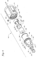
Figures 2A-2B illustrate enlarged perspective views of the exemplary connector ofFigures 1A-1B , wherein:Figure 2A is an enlarged perspective view of the connector; andFigure 2B is an exploded perspective view illustrating how a modified connector may be attached to a headgear apparatus; -
Figure 3 is a section view of the connector ofFigure 2A , taken through a plane containing a longitudinal axis of the connector, illustrating both a first coupler and a second coupler; -
Figure 4 illustrates the section of the connector shown inFigure 3 with the first coupler shown separated from the second coupler; -
Figures 5A-5B illustrate an exemplary retention device, e.g., a roller assembly, for use with the connector ofFigure 2A , wherein:Figure 5A is an enlarged perspective view of the roller assembly; andFigure 5B is a section view taken alongline 5B-5B ofFigure 2A ; -
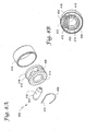
Figure 6 is an exploded perspective view of the first coupler of the connector ofFigure 2A ; -
Figures 7A-7C illustrate various aspects of the first coupler ofFigure 2A , wherein:Figure 7A is a section view of the first coupler in a partially assembled state, the view taken through a plane containing a longitudinal axis of the first coupler;Figure 7B is a perspective view of a stop member of the first coupler; andFigure 7C is a partial perspective section view of a portion of the first coupler; -
Figures 8A-8B illustrate a retention device in accordance with another embodiment of the invention, wherein:Figure 8A is an exploded partial perspective view; andFigure 8B is a perspective section view; -
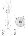
Figures 9A-9B illustrate a catheter in accordance with one embodiment of the invention, whereinFigure 9A illustrates a side elevation view; andFigure 9B illustrates a section view taken alongline 9B-9B ofFigure 9A ; -
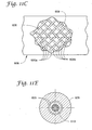
Figures 10A-10E illustrate a catheter in accordance with another embodiment of the invention, whereinFigure 10A illustrates a breakaway side elevation view;Figure 10B illustrates an enlarged breakaway view of a portion of the catheter;Figure 10C illustrates a section view taken alongline 10C-10C ofFigure 10A; Figure 10D illustrates an enlarged section view of a distal end portion of the catheter; andFigure 10E is a side elevation view; -
Figures 11A-11E illustrate a catheter in accordance with another embodiment of the invention, whereinFigure 11A illustrates a breakaway side elevation view;Figure 11B illustrates an enlarged breakaway view of a first portion of the catheter;Figure 11C illustrates an enlarged breakaway view of a second portion of the catheter;Figure 11D is a section view taken alongline 11D-11D ofFigure 11A ; andFigure 11E is section view taken alongline 11E-11E ofFigure 11B ; -
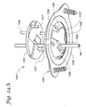
Figure 12 is a perspective view of the exemplary anchor assembly, e.g., burr hole anchor, ofFigures 1A-1B with a base of the anchor shown attached to the body, e.g., skull, and a retainer of the anchor shown before attachment to the base; -
Figure 13 is a cross section of the anchor assembly ofFigures 1A-1B as it may be implanted within the body; -
Figure 14 is an exploded perspective view of the anchor assembly ofFigures 1A-1B ; -
Figure 15 is a partial cut-away view of the anchor ofFigures 1A-1B , wherein the retainer is shown in a first or unlocked configuration corresponding to an arm of the retainer being in a first or unlocked position, and further wherein a latch of the retainer is shown in a first or unlatched position; -
Figure 16 is a perspective view of the anchor assembly ofFigures 1A-1B with the retainer shown in a second or locked configuration corresponding to the arm being in a second or locked position, and the latch of the retainer shown in a second or latched position; -
Figure 17 is a top plan view of the anchor assembly ofFigure 15 with the arm shown in the unlocked position, but with the latch shown in the latched position; -
Figure 18 is a top plan view of the anchor assembly ofFigure 16 with the arm shown in the locked position and the latch shown in the latched position; -
Figures 19A-19B illustrate section views of the anchor assembly ofFigure 17 , wherein:Figure 19A is a section view taken alongline 19A-19A ofFigure 17 but with the latch of the retainer shown in the unlatched position; andFigure 19B is a section view similar to that ofFigure 19A , but with the latch of the retainer shown in the latched position; -
Figure 20 is a bottom plan view of the anchor assembly ofFigure 17 with the latch shown in the latched position and the arm shown in the unlocked position; -
Figures 21A-21D illustrate an exemplary method for using the anchor assembly ofFigures 1A-1B , wherein:Figure 21A illustrates attachment of the anchor base to the skull;Figure 21B illustrates insertion of the anchor retainer into the anchor base;Figure 21C illustrates external portions of the anchor assembly and catheter after an implantation incision is closed; andFigure 21D illustrates unlocking and removal of the catheter at therapy completion; -
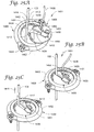
Figures 22A-22B illustrate an anchor assembly in accordance with an alternative embodiment of the invention, wherein:Figure 22A is a perspective view of the anchor assembly during assembly of an anchor retainer with an anchor base; andFigure 22B illustrates the anchor assembly after assembly and with the retainer shown in a first or unlocked configuration corresponding to an arm of the retainer being in a first or unlocked position; -
Figure 23 is a perspective view of the anchor assembly ofFigures 22A-22B with the retainer shown in a second or locked configuration corresponding to the arm being in a second or locked position; -
Figures 24A-24B illustrate an optional cap for use with the anchor assembly ofFigures 22A-22B , wherein:Figure 24A is a bottom perspective view prior to attachment of the cap; andFigure 24B is a top perspective view after attachment of the cap; and -
Figures 25A-25D illustrate an anchor assembly in accordance with yet another embodiment of the invention, wherein:Figure 25A is a perspective view of the anchor assembly during attachment of an anchor retainer with an anchor base;Figure 25B illustrates immobilization of the catheter;Figure 25C illustrates release of the catheter, e.g., at therapy completion; andFigure 25D illustrates a bottom perspective view of the anchor retainer ofFigures 25A-25C . - The figures are rendered primarily for clarity and, as a result, are not necessarily drawn to scale.
- In the following detailed description of illustrative embodiments of the invention, reference is made to the accompanying figures of the drawing which form a part hereof, and in which are shown, by way of illustration, specific embodiments in which the invention may be practiced. It is to be understood that other embodiments may be utilized and structural changes may be made without departing from the scope of the invention.
- Embodiments of the present invention are directed generally to fluid coupling devices, and to systems and methods incorporating the same. For example, embodiments of the invention may include: medical connectors for coupling a first tube (e.g., catheter) to a second tube; corresponding tubes and catheters; and body portal anchors for securing therapy delivery devices (such as tubes/catheters) relative to a body portal. Other embodiments of the invention may be directed to implantable medical systems, e.g., infusion systems (incorporating one or more of these components), for infusing a therapeutic agent into a body.
-
Figures 1A and 1B illustrate an exemplary implantable medical system (e.g., a brain infusion catheter system 100) in accordance with one embodiment of the invention.Figure 1A illustrates the system as it may be configured during use, e.g., implantation, whileFigure 1B illustrates the system removed from the body. - The exemplary infusion system may include a first medical tube, e.g.,
brain catheter 108, and a second medical tube, e.g.,secondary tube 102. Thetube 102 may have itsdistal end 104 coupled to a reservoir (e.g.,infusion pump 106, which may be identical or similar in construction to insulin pumps such as the Paradigm 515 or 715 pumps produced by Medtronic MiniMed of Northridge, California, USA) containing a volume of a therapeutic agent. Similarly, thebrain catheter 108 may have itsdistal end 110 implanted within the body 101 (as used herein, the terms "distal" and "proximal" are taken from the reference of aconnector 200 as shown inFigure 1 ). In the illustrated example, thecatheter 108 has itsdistal end 110 implanted, via aburr hole 112, at a predetermined location within abrain 114 of the patient. Aburr hole anchor 1200 may be used to secure thecatheter 108 relative to theburr hole 112. Theanchor 1200 may form part of ananchor assembly 1201 that may also include alock member 1208 described in more detail elsewhere herein. Aproximal end 116 of thecatheter 108 may extend outside thebody 101 and connect to a correspondingproximal end 118 of thetube 102, e.g., via theconnector 200. - While described herein in the context of a
pump 106, this configuration is not limiting. For example, other embodiments may replace the pump with most any medicament delivery device, e.g., syringe, drip bag, etc., without departing from the scope of the invention. - The
system 100 may, in one embodiment, be configured to deliver a therapeutic agent containing a virally mediated gene therapy as an acute treatment for Parkinson's disease. The therapeutic agent is delivered, via thetube 102 andcatheter 108, from thepump 106 to thebrain 114. This application is not limiting, however, as the system may be configured to deliver most any therapeutic agent (e.g., chemotherapy) to most any area of the body without departing from the scope of the invention. - It is noted that the terms "comprises" and variations thereof do not have a limiting meaning where these terms appear in the accompanying description and claims. Moreover, "a," "an," "the," "at least one," and "one or more" are used interchangeably herein.
- Relative terms such as left, right, forward, rearward, top, bottom, side, upper, lower, horizontal, vertical, and the like may be used herein and, if so, are from the perspective observed in the particular figure. These terms are used only to simplify the description, however, and not to limit the scope of the invention in any way.
- With this general overview, the following description will address various embodiments of the
system 100 and its components, and methods for making and using the same. While these embodiments may be described with some degree of specificity, they are nonetheless intended to be exemplary. Those of skill in the art will recognize that other embodiments are possible without departing from the scope of the invention. - It is further noted that the following description is organized by headings and subheadings for organizational purposes only. Accordingly, the particular headings/subheadings are not intended to limit in any way the embodiments described therein, i.e., alternative embodiments of a component presented under one heading or subheading of the specification may be found elsewhere (e.g., under another heading) in the specification. As a result, the specification is intended to be considered in its entirety.
- One aspect of the present invention is directed generally to fluid coupling devices and, in particular, to medical connectors such as
connector 200 shown inFigures 1A and 1B , systems, and to methods for coupling a first tube (e.g., catheter) to a second tube or other medical device. In the illustrated embodiment, the connector is shown as part of the catheter, e.g., infusion,system 100 having the partially implantedcatheter 108 and theexternal infusion pump 106. However, this configuration is not limiting as embodiments of the connectors, connector systems, and other aspects of the present invention may find use in other catheter applications, as well as in other medical and non-medical fluid systems. - Connectors in accordance with embodiments of the present invention may be configured to separate or de-couple once a threshold traction force is applied across the connector (e.g., applied to the two
tubes - An enlarged view of the
exemplary connector 200 is illustrated inFigure 2A . Theconnector 200 may include a second connector portion orcoupler 202 attached to thesecondary tube 102 and a first connector portion orcoupler 204 attached to thebrain catheter 108 as further described below (see alsoFigure 1B ). In the illustrated embodiment, thefirst coupler 204 may be supported by an optional headgear apparatus 120 (seeFigure 1 A) , which may hold theconnector 200, e.g., via a connection with the first coupler, during implantation. While illustrated as supported by aheadgear apparatus 120 inFigure 1A , theconnector 200 could alternatively be generally unsupported, e.g., supported only by the free proximal ends 116 and 118 of thecatheter 108 andtube 102, respectively, without departing from the scope of the invention. - As further illustrated in
Figure 1A , thecatheter 108 may be supported at the body by the body portal anchor, e.g.,burr hole anchor 1200. Exemplary burr hole anchors are described in more detail below. -
Figure 2B illustrates one exemplary embodiment for attaching theconnector 200 to theheadgear apparatus 120. The headgear apparatus may be formed from a series of adjustable, fabric (e.g., nylon webbing) or elastic bands (only twobands Figure 2B ). The bands may surround the head of the patient, as shown inFigure 1A , sufficiently to reduce or even prevent theheadgear apparatus 120 from substantial movement relative to the patient's head. On one or more sides, theheadgear apparatus 120 may have attached thereto (e.g., riveted) a circular snapfit receptacle 122 that, in one embodiment, is similar or identical to the female portion of a conventional metallic garment snap button. - The
first coupler 204 of theconnector 200 may optionally include an integrally formed (or otherwise attached) bracket that forms a receiving slot 207 (shown only inFigure 2B ) along one side. The receivingslot 207 may be configured to receive atab 126 of aclip 128. Once thetab 126 is fully inserted into theslot 207, theclip 128 may be generally attached to theconnector 200 until the components are intentionally disassembled. The clip may also include amale member 130 that is receivable by the snap fit receptacle 122 (themale member 130 may be similar or identical in construction to a male portion of the conventional garment snap button). Once the clip is attached to thereceptacle 122, the clip (and thus the connector 200) may pivot generally about an axis of the receptacle, e.g., providing some degree of stress relief to thecatheter 108. -
Figure 3 is a cross sectional view of theconnector 200 ofFigure 2A (taken through a plane containing a longitudinal axis of the connector) with thecouplers Figure 4 , on the other hand, is a similar section view with the couplers detached. Each of thecouplers - The
second coupler 202 may form atubular body 205 defining abore 206. Thebody 205 may be made from various materials including, for example, polyetheretherketone (PEEK), polycarbonate, and similar materials. Ahollow needle 208 may be attached to thebody 205 and extend into thebore 206 as illustrated. Theneedle 208 may define a lumen or passageway in fluid communication with thetube 102. Theneedle 208 may be affixed to thebody 205 via any acceptable technique including, for example, by adhesive. - The
body 205 also defines a smallersecondary bore 210 configured to receive thetube 102. Thetube 102 may attach to the second coupler in a manner similar to theneedle 208, e.g., with adhesive. When assembled as illustrated inFigures 3 and4 , fluid may travel from the source (e.g., pump 106 ofFigures 1A-1B ) through a lumen of thetube 102 and through thehollow needle 208. - The
connector 200 may further include a retention device, e.g.,biased retention device 300, which, in the illustrated embodiment, is attached to, or otherwise associated with, thesecond coupler 202. Theretention device 300, further illustrated inFigures 5A and5B (some structure removed for clarity in these views), may include aroller assembly 301 having anaxle 302 and acylindrical roller 304 rotatable about the axle. A tension member, e.g.,spring 306, may also be included and attached to opposite first and second ends of theaxle 302. Thespring 306 may extend circumferentially about thetubular body 205 of thesecond coupler 202 as shown. - The roller assembly, e.g., the
cylindrical roller 304, may, in a first configuration, be positioned offset from (and preferably transverse to), anaxis 214 of the first and second couplers. Theaxle 302 may be configured to move (e.g., translate) withinslots 212 formed in thebody 205 such that the axle androller 304 are movable primarily in a radial direction 308 (seeFigures 4 ,5A , and5B ) from the axis 214 (seeFigure 4 ) of the couplers. Thespring 306, which may be a conventional (e.g., stainless steel) extension spring, may provide a radially-biased force to theaxle 302 that tends to pull the roller assembly 301 (e.g., theaxle 302 and roller 304), towards theaxis 214. The other components of the roller assembly, e.g., theroller 304 and theaxle 302 may also be made from stainless steel or other materials as described below. - The
roller assembly 301 may further include a washer orflange 310. Theflange 310, which may be integrally formed with theaxle 302, assists with guiding theroller assembly 301 within theslots 212 as shown inFigures 5A and5B . - As illustrated in
Figure 5B , theroller assembly 301 of the retention device may also include a contact surface 312 (e.g., the outer surface of the roller 304). Thecontact surface 312 may, in the illustrated embodiment, form asecant 311 extending through thebore 206 of thetubular body 205 when the roller assembly is in the first configuration shown in solid lines inFigure 5B (e.g., corresponding to agrooved surface 226 of the first coupler 204 (seeFigure 4 ) being aligned with the roller 304). As further described below, theroller assembly 301, e.g., theroller 304 andcontact surface 312, may move to a second configuration (shown in broken lines inFigure 5B ), wherein thecontact surface 312 is located at or outside of thebore 206. Thus, as further described below, theroller assembly 301 may be configured to selectively interlock thesecond coupler 202 with thefirst coupler 204; and release the first coupler from the second coupler when a predetermined traction force is applied between the first and second couplers. - The
second coupler 202 may further include anoptional sleeve 216 that covers at least a portion of the outer surface of thebody 205. Thesleeve 216 may reduce the potential for patient/clinician contact with portions of theretention device 300, and may further prevent foreign objects from interfering with its operation. Exemplary materials for the sleeve include polyurethane and polypropylene. Thesleeve 216 may include a lip (e.g., a discontinuous lip as shown inFigures 3 and4 ) or other locating feature that permits it to snap or bias into place relative to thebody 205. - The
first coupler 204 is illustrated in detail inFigures 3 ,4 ,6 , and7A-7C . The first coupler may, in the illustrated embodiment, be formed by anattachment member 218 and ahousing 220, both of which may be constructed from materials similar to thebody 205 of thesecond coupler 202. - The
attachment member 218 may include anengagement portion 219 receivable within thebore 206 of thesecond coupler 202. Theattachment member 218 may also include abody portion 217 that is threadably engagable with thehousing 220. In the illustrated embodiment, theattachment member 218 is, when inserted into thebore 206, coaxial with thesecond coupler 202. - The
engagement portion 219 may include anouter surface 222 having a generally cylindrical cross section. Theroller 304 of theroller assembly 301 may be configured to engage theouter surface 222 of theengagement portion 219 in rolling contact as the engagement portion moves, e.g., translates, within thebore 206 of thesecond coupler 202. Theouter surface 222 may be formed by both anengagement surface 224 defined by a first diameter, and the grooved surface 226 (or "groove") defined by a second diameter that is less than the first diameter (see, e.g.,Figure 4 ). Thegrooved surface 226 is positioned along theengagement surface 224 so as to receive theroller assembly 301 of the retention device (e.g., the roller 304) when thefirst coupler 204 is fully engaged with thesecond coupler 202 as shown inFigure 3 . The phrases "fully engaged," "fully connected," "fully inserted," and the like are used herein to indicate that the noted components are engaged to a point where further engagement is either not possible or not necessary to the proper functioning of the connector. - The
outer surface 222 may further include a rampedsurface 228 extending between thegrooved surface 226 and theengagement surface 224. The rampedsurface 228 may act as a camming surface to permit rolling contact of theroller 304 back and forth between theengagement surface 224 and thegrooved surface 226. - The
attachment member 218 may form a tubular wall that defines apassageway 221 extending through the attachment member. Thepassageway 221 may surround or otherwise contain a needle-penetrable septum 230 in the vicinity of theengagement portion 219. Theseptum 230 may be made of most any material that permits selective penetration by theneedle 208 and self-sealing upon needle withdrawal. While other materials are possible, theseptum 230 is, in one embodiment, made of silicone. - The
septum 230 may be secured within thepassageway 221 in most any fashion. For example, in the illustrated embodiment, thepassageway 221 may form a step surface 232 (e.g., proximate the engagement portion 219) against which theseptum 230 may be located. A retainingmember 234 may then be secured (e.g., via adhesive or the like) within thepassageway 221 to secure theseptum 230 in place. The retainingmember 234 may, in one embodiment, have a taperedinterior surface 236 that assists in guiding theneedle 208 into theseptum 230 as thefirst coupler 204 is connected to thesecond coupler 202. - The
attachment member 218 may be attached to thehousing 220 before use as further described below. While the particular attachment technique may vary without departing from the scope of the invention, thebody portion 217 of the attachment member may, in the illustrated embodiment, include a threaded portion (e.g., male thread 260) operable to engage a corresponding threaded portion (e.g., female thread 258) of thehousing 220 as shown inFigures 3 ,4 ,6 , and7A . - As evident in the figures, the
body portion 217 may be of larger diameter than theengagement portion 219 to accommodate various components of thefirst coupler 204. For example, thebody portion 217 may be sized to receive aseal 238 within thepassageway 221. Theseal 238 preferably includes a lumen that extends completely through the seal. The lumen of the seal may be configured to receive theproximal end 116 of thecatheter 108 and form a substantially leak-free seal therewith. In one embodiment, theseal 238 may include a generally compliant body (e.g., made from silicone or similar material) configured to surround theend 116 of thecatheter 108, and an optional rigidtubular member 240 positioned within the lumen, e.g., proximate one end of the compliant body. The rigidtubular member 240 may serve various purposes including, for example, preventing occlusion of the lumen of theseal 238 as the seal is compressed. Moreover, themember 240 may provide an abutting surface against which theproximal end 116 of thecatheter 108 may seat during assembly of thefirst coupler 204. - The
tubular member 240 may be made from most any material that can hold its shape as theseal 238 is compressed. Exemplary materials include polysulfone and polycarbonate. Thetubular member 240 may be attached to the body of the seal (e.g., adhesive, interference fit), or it may be held in place merely by contact between the inner surface of thepassageway 221 and a step surface formed in the seal body. -
Figure 6 provides an exploded view of thefirst coupler 204. As shown in this view, theseal 238 may include atapered surface 242 to seat against a corresponding tapered surface within thepassageway 221 of theattachment member 218 as shown inFigures 3 and4 . Thefirst coupler 204 may also include acollet 244 located within thepassageway 221 of theattachment member 218. Thecollet 244 is configured to, in conjunction with thehousing 220, compress theseal 238 and clamp or otherwise immobilize thecatheter 108. Thecollet 244 may include apiston 246 that abuts theseal 238, and asplit rod 248 operable to receive thecatheter 108 therein. Thecollet 244 may further include acollet passageway 250, extending through the collet (e.g., through thepiston 246 and split rod 248), through which thecatheter 108 may pass as shown inFigures 3 and4 . Thecollet 244 may be made from a material similar to that of thebody 205. - As further described below, the
collet 244 may translate within theattachment member 218. To limit the range of travel of the collet, a stop or stopmember 252 may be provided.Figure 6 illustrates that thestop member 252 may include ears 254 (only one shown) configured to engage openings 256 (only one shown) in thebody portion 217 of theattachment member 218. Once theears 254 are engaged with theopenings 256, thestop member 252 generally limits travel and prevents removal of thecollet 244 from the attachment member 218 (unless the stop member is first removed). - As with the other components of the
first coupler 204, thehousing 220 may define apassageway 262 extending completely through the component to permit passage of thecatheter 108. At the outermost end of thehousing 220, e.g., where the catheter exits, thepassageway 262 may flare to form a bell-mouth opening 264. The large radius of the bell-mouth opening 264 may reduce strain on thecatheter 108 during the implantation period. - The portion of the
passageway 262 opposite the bell-mouth opening 264 may form a frusto-conical surface 266 diverging towards thepiston 246 of thecollet 244 as shown inFigures 3 and4 . The frusto-conical surface 266 is configured to contact two or more movable (e.g., deflectable)legs 268 of thesplit rod 248 of the collet as thehousing 220 is threaded onto theattachment member 218. As thesurface 266 contacts thelegs 268, the legs may be directed inwardly towards thecatheter 108. Thelegs 268 may mechanically (e.g., frictionally or via a biting or clamping action) engage thecatheter 108 when thehousing 220 is fully engaged with theattachment member 218 as described below. In the illustrated embodiment, thelegs 268 may include protrusions 270 (seeFigure 7C ) to assist with engagement of thecatheter 108. - The frusto-
conical surface 266 of the housing may also terminate at an abutting surface configured to contact and push against thepiston 246 of thecollet 244. As a result, when thehousing 220 is fully engaged with, e.g., threaded onto, theattachment member 218, thecollet 244 may both compress theseal 238 against an inner surface of the attachment member, and mechanically engage thecatheter 108. -
Figures 6 and7A-7C illustrate assembly of thefirst coupler 204. As shown in these views, theseptum 230 and retainingmember 234 may be secured within thepassageway 221 of theattachment member 218 as discussed above. Theseal 238,collet 244, and stopmember 252 may then be placed into theattachment member 218 and the stop member positioned such that theears 254 engage theopenings 256 as described above. To assist with aligning thestop member 252 with theopenings 256,grooves 253 may be provided along the inside surface of theattachment member 218 as shown inFigure 7C . - Once the
seal 238 andcollet 244 are positioned, thehousing 220 may be placed over theattachment member 218 as shown inFigure 7A . When thehousing 220 is sufficiently engaged with theattachment member 218,optional tabs 271 may be inserted and secured within openings 272 (only one opening shown inFigure 6 ). Thetabs 271 may protrude past the interior surface of thehousing 220 such that, when the housing is unthreaded and withdrawn from theattachment member 218, the tabs engage a raisedlip 274 of the attachment member to prevent inadvertent component separation. Thetabs 271 may secure to thehousing 220 via most any acceptable method including, for example, adhesive or press fit. - As illustrated in the figures, see, e.g.,
Figure 7C , thecollet 244 may include clocking features (e.g., one ormore keys 276 located on the outer surface of the piston 246) that engage the attachment member 218 (engage either or both of thekeyways 253 andkeyways 278 formed on the inner surface) and prevent relative rotation. The external surface of theattachment member 218 may also include one or more keys 280 (seeFigure 6 ) that engage corresponding keyways (visible inFigure 4 ) on an inner surface of thesecond coupler 202 to prevent relative rotation of thecouplers - At this point, the
catheter 108 may be inserted into thefirst coupler 204, via the bell-mouth opening 264, until it bottoms out in the seal 238 (e.g., contacts the tubular member 240) as shown inFigure 7A . Thecatheter 108 may include markings, e.g., laser markings (further described below), that assist the clinician in determining if the catheter is fully inserted. Thehousing 220 may then be moved until thefemale thread 258 engages themale thread 260 of theattachment member 218. Subsequent threading of thehousing 220 onto theattachment member 218 results in compression of theseal 238, thereby sealing the fluid path between thefirst coupler 204 and thecatheter 108. - Moreover, relative movement between the housing and attachment member results in engagement of the frusto-
conical surface 266 with thelegs 268 of thecollet 244, which may eventually apply a mechanical force (e.g., a gripping or clamping force) to thecatheter 108. The first coupler 204 (e.g., the collet 244) is preferably configured to ensure that the gripping force on the catheter is greater than the intended breakaway force of theconnector 200. As a result, when a traction force is applied to thetube 102 and thecatheter 108, thecouplers catheter 108 dislodges from the first coupler. - Preferably, the
legs 268 of thecollet 244 are configured to engage and grip thecatheter 108 only after theseal 238 has been compressed. As a result, axial catheter movement resulting from seal compression may be accommodated before the collet immobilizes thecatheter 108. - The
catheter 108 may be configured such that it can be satisfactorily immobilized by thecollet 244 without occlusion of the fluid passageway. For example, in one embodiment, the catheter could be made from an elastomeric material (pure or blended) such as a polymer, silicone, or the like. Exemplary embodiments of thecatheter 108 are described in more detail below. - The
tube 102, may, on the other hand, be constructed from conventional medical tubing such as polyurethane, silicone, or co-extrusions such as silicone/nylon or silicone/polyurethane. Alternatively, thetube 102 could be made from plasticized polyvinyl chloride (e.g., flexible PVC). In one embodiment, thetube 102 may have an inner diameter of about 0.07 millimeters (mm) to about 0.08 mm (e.g., about 0.076 mm) and an outer diameter of about 1.4 mm to about 1.5 mm (e.g., about 1.47 mm). While exemplary embodiments of the catheter and tube are so described herein, variations in material, construction, and size of thecatheter 108 andtube 102 are certainly possible without departing from the scope of the invention. - Once the
housing 220 is completely threaded onto theattachment member 218, thefirst coupler 204 is generally configured as shown inFigure 4 . Thesecond coupler 202 may then be positioned proximate thefirst coupler 204 such that thebore 206 is generally aligned with theengagement portion 219. The engagement portion may then be slid into thebore 206 such that theroller 304 contacts theouter surface 222 of the engagement portion. This contact results in theroller assembly 301, e.g., theroller 304, being displaced outwardly (upwardly inFigure 4 ) against the biasing force of thespring 306. Theroller 304 may then roll along theengagement surface 224 until it reaches the rampedsurface 228, at which point the roller may roll down the ramped surface and engage (contact) thegrooved surface 226. - The biasing force of the
spring 306 tends to keep theroller assembly 301 engaged with thegrooved surface 226 during operation. To prevent backlash in theconnector 200, thesecond coupler 202 and thefirst coupler 204 may include corresponding abuttingsurfaces Figure 4 ), that contact one another once the couplers are fully connected as shown inFigure 3 . - While not wishing to be bound to any particular embodiment, the roller assembly may utilize an
axle 302 having a diameter of about 0.050 inches (in) (1.27 mm) and the roller 304 (which may be made from acetal resin, PEEK, nylon, or the like) may have an outer diameter of about 0.09 in (2.286 mm). In this embodiment, thegrooved surface 226 may be recessed about 0.021 in (0.5334 mm) below theengagement surface 224, and the rampedsurface 228 may form an angle of about 50 degrees from the engagement surface. - As the
second coupler 202 is attached to thefirst coupler 204, theneedle 208 associated with the second coupler may pierce theseptum 230 associated with thefirst coupler 204, thereby providing a fluid path from thesecond tube 102 to the first tube (e.g., the catheter 108). As a result, therapeutic agent contained in the infusion pump 106 (seeFigures 1A-1B ) may be delivered to the body through thetube 102 andcatheter 108 in accordance with any desired infusion profile. - The
retention device 300 is configured to release thefirst coupler 204 from thesecond coupler 202 once a predetermined traction force (the "breakaway force") is applied between the couplers, e.g., between thetube 102 and thecatheter 108. In the illustrated embodiment, various features affect the breakaway force including, for example, the depth of thegrooved surface 226, the angle of the rampedsurface 228, the diameter of theroller 304, the friction of the roller about theaxle 302, and the spring force of thespring 306. While not wishing to be bound to any particular range of parameters, embodiments of the present invention may provide aconnector 200 having a breakaway force of about 1 pound force (lbf) to about 10 Ibfand, preferably about 1 lbf to about 5 lbf, and more preferably, about 1.5 lbf to about 3 lbf. - When the predetermined traction force is reached, the
roller 304 may move radially outward as it rolls from thegrooved surface 226, along the rampedsurface 228, to theengagement surface 224. Theroller 304 may continue to roll along theengagement surface 224 until the couplers separate. - While described and illustrated herein utilizing the
retention device 300, other retention mechanisms are possible without departing from the scope of the invention. For example,Figures 8A and 8B illustrate analternate retention device 400. In this embodiment, the device includes a roller assembly having anaxle 402 and aroller 404 rotatable about the axle. Theaxle 402 may be formed as part of a spring clip, e.g., C-shapedclip 406. Theclip 406 may be configured to fit within acircumferential groove 408 formed in thebody 410 of a second coupler. Theroller 404 may be similarly contained within aslot 412 formed in the body. Thebody 410, while only partially illustrated inFigures 8A and 8B , is understood to be substantially similar to thebody 205 of thecoupler 202 described above (e.g., it includes abore 414 to receive theattachment member 218 substantially as described above). Asleeve 416 similar to thesleeve 216 already described herein may also be included. - As with the
retention device 300, the roller assembly, e.g.,roller 404, may include acontact surface 418 formed by the outer surface of the roller. Thecontact surface 418 may form a secant through thebore 414 of thetubular body 410 when the roller is in a first position as shown inFigure 8B . When the attachment member is inserted into thebore 414, theroller 404 may move to a second position (see broken line representation of axle 402) wherein the contact surface is located outside of the bore. Movement of theroller 404 may be accommodated via deflection of theclip 406 as may occur during insertion and removal of thefirst coupler 204 from thebore 414. - As with the
device 300, thedevice 400 may engage theouter surface 222 of the attachment member 218 (seeFigure 4 ) in rolling contact. Moreover, theroller 402 may be biased in a generally radial direction to maintain rolling contact with theattachment member 218 of the first coupler during insertion/removal. - Connectors in accordance with embodiments of the present invention provide tubing/catheter couplers that breakaway or separate from one another when a predetermined traction force is applied to the couplers and/or to their associated tubes/catheters. Moreover, the retention device that interconnects the two couplers may minimize frictional engagement therebetween by providing rolling contact engagement. As a result, the breakaway force required to separate the couplers is substantially repeatable, avoiding the variability commonly associated with friction-based retention interfaces. Connectors in accordance with embodiments of the present invention further provide an upstream coupler (e.g., a coupler attached to an implanted catheter) that minimizes exposure to contamination even when the couplers of the connector separate. Accordingly, replacement or sterilization of the upstream catheter and/or coupler may be unnecessary in the event inadvertent separation of the connector occurs.
- Connectors in accordance with embodiments of the present invention further provide a fluid flow path with minimal dead volume (the static volume that is filled before fluid is transferred through the connector). Reduced dead volume is advantageous as it may decrease the volume of wasted therapeutic agent. In the illustrated embodiment of
Figure 3 , the connector (e.g., theregion 286 between thesecond tube 102 and theneedle 208, and theregion 288 between theseptum 230 and the seal 238) is designed to provide a low dead volume. For instance, connectors in accordance with embodiments of the present invention may have a dead volume of less than 20 microliters, and preferably less than 10 microliters, e.g., nominally about 7 microliters. - As described above, the first tube or
catheter 108 may be implanted and used to deliver the therapeutic agent to the body. Accordingly, thecatheter 108 may be configured such that it can be satisfactorily immobilized by thecollet 244 without occlusion of the fluid passageway. For example, as stated above, the catheter could be made from an elastomeric material (pure or blended) such as a polymer, silicone, or the like. - While some exemplary catheters may be constructed as generally uniform tubes, catheters in accordance with other embodiments of the invention may be configured to include an elongate tubular core or core member 107 (see, e.g.,
Figure 7A ) made from longitudinally flexible tubing that is resistant to compression and collapse, e.g., glass (e.g., silica or quartz) tubing, PEEK tubing, or stainless steel tubing.Figures 9A-9B illustrate an exemplary catheter having such a construction. - The
core 107 may include a proximal end positioned at or near theproximal end 116 of thecatheter 108, and a distal end positioned at or near thedistal end 110 of the catheter as shown inFigure 9A . Thecore 107 may also include a tubular body forming alumen 117 spanning between the proximal and distal ends of the core. In the illustrated embodiment, thetubular core 107 may have an inner (e.g., lumen 117) diameter of about 80 micrometers to about 120 micrometers (e.g., about 100 micrometers) and an outer diameter of about 200 micrometers (e.g., about 193 micrometers), yielding a radial or wall thickness of about 50 micrometers or less. Anexemplary core 107 may be a flexible synthetic fused silica capillary having an optional thin protective polymer (e.g., polyimide) coating (forming an intermediate layer between the core and an outer covering or jacket 109) such as the TSP line of products sold by Polymicro Technologies, LLC, of Phoenix, AZ, USA. - The flexible outer covering or
jacket 109 may be formed over thetubular core 107, e.g., it may surround the tubular core and be secured or otherwise fixed relative to the core's outer surface. While the flexible outer covering or jacket is described in the illustrated embodiments as anelastomeric jacket 109, this construction is not limiting as other outer covering embodiments are certainly possible without departing from the scope of the invention. - In one embodiment, the
jacket 109 may have an outer diameter that is about 3 or more times larger, and preferably about 4 or more times larger (e.g., about 4 to about 6 times larger), than the outer diameter of thetubular core 107. For example, the outer diameter of thejacket 109 may be about 0.8 mm to about 1.2 mm (e.g., about 1 mm). - The
jacket 109 may be formed of an elastomeric material having a radial compliance that is greater than a radial compliance of thetubular core 107. In one embodiment, theelastomeric jacket 109 is made from a material selected from the group consisting of polyurethane and silicone. As a result of using a relatively compliant material, the flexible outer covering or jacket may permit high mechanical clamping/indentation forces to be applied to the catheter 108 (e.g., by theconnector 200 or, as described below, by the anchor 1200) to immobilize it, while the more radially rigidtubular core 107 prevents catheter occlusion under such high forces. While not limited to any particular hardness, thejacket 109 may, in one embodiment, have a hardness of about 50 to about 60 Shore D, e.g., about 55 Shore D (at the completion of manufacture). - As illustrated in
Figure 9A , thetubular core 107 may, in some embodiments, protrude longitudinally beyond the jacket or covering 109 at one or both ends of the catheter (e.g., beyond adistal end 119 of the jacket as shown) by adistance 124 of, e.g., about 10 mm or more. Stated alternatively, thejacket 109 may terminate a distance of about 10 mm short of the distal end of thecore 107. -
Figure 9B illustrates a section view of thecatheter 108 taken alongline 9B-9B ofFigure 9A . As illustrated in this view, the catheter may optionally include one or more locator markings. For instance, a marker band, e.g., a fluoroscopic orradiopaque marker band 131, may be located at or near thedistal end 119 of the outer covering (e.g., jacket 109). Theband 131 may include platinum, iridium, or a similar material that may permit detection of the band with fluoroscopic or x-ray imaging. Such a configuration may be beneficial, for example, during implantation of the catheter into the body. - The
catheter 108 may further optionally include other locator markings, e.g., longitudinal markings 132 (only two shown oncatheter 108 inFigure 9A ). Thelongitudinal markings 132 may be evenly spaced and include some colorant (e.g., titanium dioxide) to permit visual indication of catheter implant depth. Themarkings 132 may also be used to determine proper placement of theproximal end 116 of the catheter within theconnector 200. -
Figures 10A-10E illustrate a catheter, e.g., acatheter 508, in accordance with an alternative embodiment of the invention. Thecatheter 508 may be similar in some respects, and be used in place of, thecatheter 108. - Like the
catheter 108, thecatheter 508 may include a radially rigid yet longitudinally flexible tubular core or core member 507 (of a first material, e.g., PEEK tubing) having a distal end and a proximal end. A flexible outer covering orjacket 509 may surround the core (see, e.g.,Figures 10A and 10D ). However, instead of a single tubular core member extending along the catheter, thecatheter 508 may incorporate a separate tubular tip ortip member 510, e.g., a composite tip member made of a second material different than a material of thecore member 507. Thetip member 510, like thecore 507, may also have proximal and distal ends as shown inFigure 10A . - The
tip 510 may be configured as a relatively rigid (both radially and longitudinally) member. For instance, in one embodiment, thetip 510 may be formed from fused silica glass tubing. In another embodiment, thetip 510 may be made from steel, e.g., type 304 stainless steel hypodermic tubing. The proximal end of thetip 510 may be positioned to abut the distal end of the core 507 (e.g., be positioned in abutting contact atlocation 511 as illustrated inFigures 10A and 10B ) such that a generally continuous lumen extends or is established from the proximal end of the core 507 to the distal end of thetip 510. While described herein as abutting one another, in practice the twomembers jacket 509 may effectively seal the interface and provide a generally continuous lumen as described. - While not wishing to be bound to any particular construction, the materials and geometry of the
tip 510 andcore 507 may be selected to produce a bending stiffness ratio (ratio of the bending stiffness of the tip to bending stiffness of the core) of about 24:1. - The
jacket 509 may surround or encase longitudinal sections or portions of both thetip 510 and thecore 507 as further described below. As with thecatheter 108, the distal end of thetip 510 may protrude a preset distance beyond a distal end of the jacket as shown inFigure 10A . Thetip 510 may also extend into the jacket 509 a distance that is sufficient to ensure retention of the tip. For example, in one embodiment, the catheter length (including the protrudinglength 124 of the tip 510) is about 400 mm (about 16 inches), while the tip extends into the jacket adistance 134 of about 20 mm, (about 0.8 inches). -
Figure 10C illustrates a cross section of thecatheter 508 taken alongline 10C-10C ofFigure 10A , whileFigure 10D illustrates a section view of the distal end of thejacket 509. These views clearly illustrate the marker band 131 (as described above) formed, at least in one embodiment, as a ring located around thetip 510 and surrounded by thejacket 509. In one embodiment, the marker band may extend ashort distance 136, e.g., about 1 mm, from the end of the jacket. As with thecatheter 108, thecatheter 508, e.g.,jacket 509, may also include the longitudinal length markings 132 (only two shown inFigure 10E ). Themarkings 132 andband 131 may be visible from any radial position, e.g., they may extend 360 degrees around the catheter. - In still yet other embodiments, strengthening members, e.g., braided members helically-wound about a longitudinal length or portion of the catheter, and/or straight longitudinal members, may be provided. For example, strengthening members may be sandwiched between the core and the flexible outer covering or jacket (e.g., such that they are surrounded by the jacket), or alternatively embedded within the jacket. Exemplary strengthening members may include polyester (e.g., polyethylene terephthalate (PET)), synthetic polymers such as Kevlar brand fiber (sold by E. I. du Pont de Nemours of Wilmington, DE, USA), and liquid crystal polymers. In other embodiments, steel may be used to form the strengthening members. Such strengthening members may be incorporated into any of the catheter embodiments (e.g., 108, 508, and 608, the latter of which is described below) described herein.
- An
exemplary catheter 608 incorporating such strengthening members is shown inFigures 11A-11E . Thecatheter 608 may be similar in most respects to thecatheter 508. For instance, it may include a core or core member 607 (e.g., PEEK core) and a flexible outer covering or jacket (e.g., polyurethane jacket) 609 optionally having locator markings such asmarker band 131 and longitudinal markings (not shown) as already described herein. As a result, a section taken throughline 11D-11D (seeFigure 11D ) is similar in most respects to the corresponding section taken throughline 10C-10C ofFigure 10A (see, e.g.,Figure 10C ). - A
tip 610 substantially similar to thetip 510 already described above may also be included. Thejacket 609 may encase at least sections of both thecore 607 and thetip 610 as further described below. Once again, as shown inFigure 11B , thetip 610 may abut thecore 607 at a location 611 (e.g., offset adistance 634 from the distal end of the jacket) such that a continuous lumen is formed through the catheter. Thetip 610 may further extend from the distal end of the jacket by adistance 124 as already discussed above. - Unlike the
catheter 508, however, thecatheter 608 may further include one ormore strengthening members 605 extending along at least a portion of a length of the catheter. In the illustrated embodiment, the strengtheningmembers 605 may form a tubular braid located coaxially about portions of one or both of thecore 607 and the tip 610 (note: themembers 605 are shown diagrammatically in the figures). Stated another way, theindividual members 605 may include a plurality offirst braided members 605a helically wound about a longitudinal portion of the catheter 608 (e.g., about at least portions of the core and/or the tip 510) in a first or clockwise direction, and a plurality of second braidedmembers 605b helically wound about the longitudinal portion in a second, opposite or counterclockwise direction (as shown inFigure 11C ) such that individual members interweave with one another. Other embodiments may include, alternatively or in addition, one or morelongitudinal strengthening members 606 extending along portions of one or both of the core and the tip as also shown inFigure 11C . - In one embodiment, the strengthening members 605 (e.g., the
members jacket 609 as shown inFigures 11C and 11E , the latter of which is a section view taken alongline 11E-11E ofFigure 11B . These strengtheningmembers 605 may extend along at least a portion of thecatheter 608. For example, in the embodiment illustrated inFigure 11A , themembers 605 may terminate adistance 138 short of the distal end of thejacket 609. The strengtheningmembers 605 may also extend towards the proximal end of the catheter at least beyond the location 611 (e.g., so that they surround the distal end of thecore 607 and the proximal end of thetip 610 as shown) to increase strain relief to the catheter in the vicinity of thelocation 611. In the illustrated embodiment, the strengtheningmembers 605 may extend to the proximal end of thecatheter 608. - While not wishing to be bound to any particular embodiment, the
exemplary catheter 608 may again be about 400 mm (16 inches) long (including the protruding tip 610). The distance 138 (the termination offset of the strengtheningmembers 605 from the distal end of the jacket 609) may be about 10 mm (0.4 inches), while thedistance 634 at which thecore member 607 abuts the tip member, may be about 20 mm (0.8 inches). Thepreset distance 124 may again be about 10 mm (0.4 inches), which may thus be equal to about 1/3 of the total length of thetip member 610. The small diameter, protruding distal tip of the core may assist in, for example, penetrating tissue during implantation. - The catheter embodiments illustrated in
Figures 10A-10E and11A-11E may provide a catheter having: adistal end section 140 defined by the protruding (e.g., stainless steel or glass)tip member 610; aproximal end section 142 defined by the portion of the catheter incorporating thecore member 607; and amedial section 144 between the distal and proximal end sections (see, e.g.,Figure 11A ). Thejacket 609 may extend along and surround both themedial section 144 and theproximal section 142. Thedistal end section 140 may thus have a longitudinal portion with a uniform outer diameter less than an outer diameter of one or both theproximal end section 142 and themedial section 144. As a result of the different material of thecore 607 andtip 610, thedistal end section 140 may also have a bending stiffness that is greater than a bending stiffness of theproximal end section 142. - The outer covering or
jacket 109 may be applied to the respectivetubular core 107 in any known fashion (the following description may also apply to thejackets respective cores 507 and 607). For example, it may be applied over thecore 107 through a secondary extrusion process. Alternatively, the outer covering orjacket 109 may form a tube which slides over thetubular core 107 with clearance. In the case of the latter, two or more abutting tubing segments may be employed to produce thejacket 109. These multiple segments may also be beneficial in providing the proper spacing for thelongitudinal markings 132. A shrink-wrap tube may then be placed over the assembled tubes and the entire assembly heated. Any optional strengthening members (e.g., woven fibers 605) may also be placed over thetubular core 107 or theouter covering 109 before the heat shrink tube is applied. Subsequent heating of the assembly may cause theouter covering 109 to melt and the shrink-wrap tube to constrict. Thus, the shrink-wrap tube may force the melted outer covering (and optional strengthening members) inwardly towards thetubular core 107 and bond to the same. The shrink-wrap tube may then be removed to produce thecatheter 108. - Embodiments of the instant invention may also be directed to anchor devices and assemblies and to corresponding systems and methods for securing a therapy delivery device relative to a surface, e.g., a surface of a body. For example, exemplary anchor assemblies and devices described herein may be configured to secure a therapy delivery device (such as a stimulation lead or infusion catheter 108) that is partially implanted through a skin-covered body portal. Moreover, these anchor assemblies may be manipulated from a location outside of the skin (e.g., outside of the patient's body) to release the therapy delivery device, e.g., at therapy completion. Once released, the device may be withdrawn from the body, e.g., by application of an external force or other action. As a result, the therapy delivery device may be removed from the patient without a separate surgical procedure.
- While the term "skin" is used herein to identify an exemplary covering of the body portal, this term is not to be read in a limiting sense. That is, embodiments of the present invention are equally applicable to portals covered by most any material, including grafts, medical dressings, and other synthetic and biologic coverings, as well as to uncovered portals.
- In the described embodiments, an anchor portion of the
anchor assembly 1201 is configured as the burr hole anchor 1200 (seeFigure 1A ). The anchor may be part of thesystem 100 for infusing a therapeutic agent into the patient's brain via thebrain catheter 108 passing through theburr hole 112 formed in the skull. Theanchor 1200, which may be subdermally located, may be used to secure the catheter relative to the burr hole. Theanchor assembly 1201 may include theanchor 1200 as well as thelock member 1208 to release thecatheter 108 from the anchor, e.g., at therapy completion. - While described herein in the context of burr hole anchors and corresponding infusion systems, anchor assemblies and systems in accordance with embodiments of the present invention may find use in most any medical (or non-medical) application that involves access through a portal formed in a surface.
-
Figures 1A and 1B illustrate the exemplary implantable medical system, e.g., braininfusion catheter system 100. Once again, theexemplary infusion system 100 may include the first medical tube, e.g., thebrain catheter 108, partially implanted within thebody 101. The secondmedical tube 102 may also be provided having itsdistal end 104 coupled to an external reservoir (e.g., infusion pump 106) containing a volume of the therapeutic agent. In the illustrated example, thebrain catheter 108 has an indwelling portion, e.g., thedistal end 110, implanted through a body portal (e.g., burr hole 112) and located at a predetermined location within thebrain 114 of the patient. An external portion (e.g., the proximal end 116) of thebrain catheter 108 may be routable through skin covering the skull 113 (seeFigure 12 ) and extend outside thebody 101 where it connects to the correspondingproximal end 118 of thetube 102, e.g., via theconnector 200. - The
breakaway connector 200, as described above, may include the first coupler orconnector portion 204 coupled to thebrain catheter 108 and the second coupler orconnector portion 202 coupled to thetube 102 as shown inFigure 1B . Once again, thefirst coupler 204 may be operable to separate from thesecond coupler 202 when a traction force applied between thetube 102 and thebrain catheter 108 reaches a predetermined threshold value. That is, theconnector 120 may be configured to separate once a predetermined traction force is applied across the connector, e.g., between the twotubes connector 200 may utilize either frictional or non-frictional (e.g., magnetic) interfaces to achieve the breakaway function. As discussed above, the breakaway function may be beneficial to reduce inadvertent catheter dislodgement as the result of snagging of thetube 102 orother system 100 components on surrounding objects. - As already described herein, the
connector 200 may be supported, e.g., pivotally supported, by the optional headgear apparatus 120 (seeFigures 1A and2B ) formed from a series of adjustable, fabric (e.g., nylon webbing) or elastic bands. Theheadgear apparatus 120 may hold the connector, e.g., via a connection with thefirst coupler 204, during the implantation. While illustrated as supported by theheadgear apparatus 120 inFigure 1A , theconnector 200 could alternatively be generally unsupported, e.g., supported only by the free proximal ends 116 and 118 of thecatheter 108 andtube 102, respectively, without departing from the scope of the invention. Theexemplary breakaway connector 200 is described elsewhere herein. While theexemplary connector 200 is described herein, other embodiments that utilize connector configurations providing an alternate breakaway configuration are certainly possible. For example, connectors using a snap-fit lock (e.g., similar to that disclosed byLickliter in U.S. Pat. No. 6,902,207 ) or those incorporating a magnetic lock (e.g., similar to that disclosed byCator in U.S. Pat. No. 3,181,895 ) could be used. - The
system 100 illustrated inFigures 1A and 1B may further include a portal anchor device, e.g., theburr hole anchor 1200. Theanchor 1200 may attach to the body, e.g., to theskull 113, in or near theburr hole 112. Theanchor 1200 may be used to selectively immobilize thecatheter 108 relative to theburr hole 112. In the illustrated embodiment, all, or substantially all, of theanchor 1200 is positioned subdermally (e.g., below the skin). Theanchor 1200 forms part of theanchor assembly 1201 that further includes thelock member 1208 capable of selectively releasing thebrain catheter 108 from the anchor. The lock member (further described below) may be releasable, or otherwise actuatable, from a location outside of the skin. - While the embodiments described and illustrated herein are directed to catheter implantation and anchoring, this is not limiting as most any other therapy delivery device (e.g., stimulation lead) may be used with the anchor embodiments described herein without departing from the scope of the invention.
-
Figure 12 is a perspective view of the portal, e.g., burr hole, site and illustrates an anchor system in accordance with one embodiment of the invention. Theburr hole 112 may be formed through theskull 113 in a known manner prior tocatheter 108 implantation. In the illustrative embodiment, theanchor 1200 includes a base 1202 that at least partially surrounds the portal (burr hole 112) and is attachable to tissue surrounding the portal, e.g., to theskull 113, with fasteners, e.g.,bone screws 1204, or the like. Theanchor 1200 may further include a retainer 1206 (shown exploded from the base inFigure 12 ) that is attachable or otherwise securable to thebase 1202 and is capable of selectively gripping or otherwise immobilizing thecatheter 108. In some embodiments, thebase 1202 may be optional. That is, theretainer 1206 could be positionable in or near the burr hole portal beneath the skin, where it may be secured to the skull in another manner, e.g., friction. Theretainer 1206 may include amovable arm 1210 and a latch orlatching device 1212, each of which is described in more detail below. The components of the retainer 1206 (e.g.,body portion 1230 and arm 1210) may be constructed of most any biocompatible material, but are, in one embodiment, made from titanium. -
Figure 13 illustrates a cross sectional view of theanchor assembly 1201 andcatheter 108 after implantation. As evident in this view, theanchor 1200, e.g., thebase 1202 andretainer 1206, are operable to be subdermally located (i.e., beneath the skin 111) AsFigure 13 further illustrates, thearm 1210 may move from a first or unlocked position shown inFigure 12 (corresponding to the retainer being in a first or unlocked configuration), to a second or locked position shown inFigure 13 (corresponding to the retainer being in a second or locked configuration). In the second position, opposing retainingsurfaces 1234 and 1242 (seeFigure 14 ) may mechanically engage thecatheter 108 and hold it in place relative to theburr hole 112. Thelock member 1208 may be configured to hold or secure thearm 1210 in the second position. Thecatheter 108 and thelock member 1208 may, at the completion of implantation surgery, extend outwardly through theskin 111 covering theskull 113 and the now-implantedanchor 1200. -
Figure 14 is a perspective view of the base 1202 with theretainer 1206 exploded to illustrate an exemplary construction. In this embodiment, theretainer 1206 includes the planar, disk-shaped body orbody portion 1230 that defines a mounting plane. Thebase 1202 may form a peripheral portion of theanchor 1200 that defines acentral opening 1214. An inner surface of this peripheral portion may form aledge 1216 to receive and support aperipheral edge 1232 of thebody portion 1230 when the retainer is attached to the base in or near the central opening. - The
ledge 1216 may, in one embodiment, be formed by a plurality ofteeth 1218 protruding from the inner surface of the peripheral portion into thecentral opening 1214. Arecess 1220 may be defined between adjacent pairs of the plurality ofteeth 1218. - The
body portion 1230 may further include afirst retaining surface 1234 defined by an edge of a cutout or pie-shapedopening 1236 extending through theperipheral edge 1232. Thefirst retaining surface 1234 may span from an interior of thebody portion 1230 to a location at or near theperipheral edge 1232. As further explained below, thefirst retaining surface 1234 may be configured to mechanically engage the catheter 108 (not shown inFigure 14 ) during use. - The
arm 1210 may be movably, e.g., pivotally, attached to thebody portion 1230. For example, thearm 1210 may include asecond retaining surface 1242 that joins first andsecond plate members plate members body portion 1230 when thearm 1210 is assembled with the body portion. - The two
plate members openings 1244 that align with anopening 1246 in thebody portion 1230 such that apin 1248 may be inserted through the openings (thepin 1248 may engage either thearm 1210 or thebody portion 1230 with interference) as shown inFigure 15 . Thearm 1210 may thus pivot about an axis of thepin 1248. Thesecond retaining surface 1242, e.g., thearm 1210, is therefore movable, relative to the first retaining surface, between the first position configured to receive the catheter 108 (see, e.g.,Figure 15 ), and the second position configured to mechanically engage the catheter (e.g., via friction or via a biting or clamping action) against the first retaining surface 1234 (see, e.g.,Figure 16 ). Thus, thecatheter 108 may be immobilized or otherwise locked relative to theanchor 1200 via a pivoting motion applied to thearm 1210. - In embodiments wherein the
catheter 108 is engaged via a biting action or a high frictional force, the catheter may be constructed of a compliant material that can withstand the contact forces of the first and second retaining surfaces as already described herein (see description ofcatheters - When the
arm 1210 is in the first position, thesecond retaining surface 1242 may be oblique to thefirst retaining surface 1234, e.g., a line contained within the second retaining surface may intersect a line contained within the first retaining surface at an acute angle. This configuration provides for a larger opening in which to initially insert and position the catheter as shown inFigure 15 . However, when the arm is in the second locked position (see, e.g.,Figure 16 ), the first and second retaining surfaces are generally parallel to one another to permit generally equivalent contact force on the catheter regardless of the catheter's position along the retaining surfaces. - In addition to the
anchor 1200, theanchor assembly 1201 may further include thelock member 1208. Thelock member 1208 may be formed by an elongate member orcord 1250 that is removably coupled to the anchor, e.g., to thebody portion 1230 of theretainer 1206. In one embodiment, thelock member 1208, e.g., thecord 1250, protrudes away from thebody portion 1230 generally orthogonally from the mounting plane defined by the body portion. Thecord 1250, in the illustrated embodiment, is configured to protrude through an opening or incision in theskin 111 as shown inFigure 13 . In one embodiment, theelongate cord 1250 is made from stainless steel stranded cable, e.g., 1 x 7, 1/64 inch diameter. - The
exemplary lock member 1208 may also include afirst end 1252 and asecond end 1256. Thefirst end 1252 may be attachable to thebody portion 1230, e.g., detachably inserted into or otherwise received within anopening 1254 formed in the body portion (see, e.g.,Figure 14 ). Theopening 1254 may position thelock member 1208, e.g., thefirst end 1252, such that it may interact with thearm 1210 as further described below. In the illustrated embodiment, thelock member 1208 is securely retained in thebody portion 1230 during the implantation period and up until thelock member 1208 is intentionally removed. Such secure retention may be achieved in any number or ways, some of which are described in more detail below. - The first and
second ends lock member 1208 may be formed bysleeves sleeve 1252a at thefirst end 1252, the tolerance of thefirst end 1252 relative to theopening 1254 may be closely controlled without concern for the size, material, or structure of thecord 1250. In one embodiment, thesleeves - The
second end 1256, e.g., thesleeve 1256a, of thelock member 1208 may be used to provide a gripping surface to assist in lock member removal. In one embodiment, thesleeve 1256a may be used to secure an optionalgrasping loop 1258 as shown inFigures 12 and14 . Theloop 1258 may be sized to permit insertion of a finger to assist the clinician with lock member removal. - The
lock member 1208 is movable from an engaged state in which the lock member is coupled to theretainer 1206 to hold thearm 1210 in the second position (see, e.g.,Figures 13 and16 ), to a disengaged state in which the lock member releases the arm from the second position. Thelock member 1208 is preferably movable from the engaged state to the disengaged state via manipulation of the lock member from outside the skin, e.g., via application of a traction force to thesecond end 1256 of the lock member to remove the latter from theretainer 1206. - The
lock member 1208 is configured to secure or lock thearm 1210, e.g., thesecond retaining surface 1242, in the second or locked position, as shown inFigure 16 , by engaging alocking portion 1260 of the arm as further described below. While not visible inFigure 16 , the arm may include alocking portion 1260 on both thefirst plate member 1238 and the second plate member 1240 (seeFigure 20 ). - The
lock member 1208 may be retained within thebody portion 1230 via a variety of methods. For example, in one embodiment, thefirst end 1252 may be sized such that it is received into the opening with an interference or press fit, wherein the interference provides a suitable retention force. In another embodiment, theopening 1254 may form a slot that receives thefirst end 1252. Such a slot may provide advantages including added flexibility of thebody portion 1230 during insertion/removal of thelock member 1208. As a result, tolerance control between thefirst end 1252 and thebody portion 1230 could potentially be relaxed. - In yet another embodiment, a cantilever spring may be provided that is integral or otherwise associated with the
opening 1254. The spring and opening may both provide a suitable retention force between thelock member 1208 and thebody portion 1230 without necessitating the elevated tolerance accuracy typically associated for press fits. In still yet another embodiment, thefirst end 1252 of the lockingmember 1208 may be sized to freely slip into theopening 1254. The lockingportion 1260 of eacharm 1210 could then mechanically interfere with thefirst end 1252 to provide a frictional retention force. In one embodiment, this retention force may be about 0.1 pounds force (lbf) to about 1.1 (lbf). However, this range is exemplary only and embodiments that release upon the application of most any force are certainly possible without departing from the scope of the invention. In this embodiment, each lockingportion 1260 may basically form a cantilevered spring that allows insertion, despite the mechanical interference, of thefirst end 1252 of thelock member 1208 into thebody portion 1230. In still other embodiments, a detent bump 1261 (seeFigure 16 ) may be provided that creates a detent action to releasably hold thearm 1210 in the unlocked position. Due to the spring-like action of each lockingportion 1260, a suitable detent holding force may be created. - The
retainer 1206 may further include thelatch 1212 as shown inFigure 14 (also shown in section inFigures 19A and 19B ). Thelatch 1212 may be used to secure theretainer 1206 relative to thebase 1202. While shown inFigure 14 as a separate component attached to thebody portion 1230, thelatch 1212 could, in other embodiments, be formed as an integral part of the retainer, e.g., deflectable snap fit tabs as further described below. - The
latch 1212 may include alatch plunger 1262 that is biased outwardly by a biasing member, e.g.,spring 1264. Thelatch plunger 1262 may be formed by first andsecond plate members nose 1270. A pin, e.g., retainingpin 1271 may also extend between theplate members latch plunger 1262 may thus form a clevis that extends over both sides of thebody portion 1230 when assembled. - The
latch 1212, e.g.,latch plunger 1262, is preferably movable from a first or unlatched position that is at or within theperipheral edge 1232 of the body portion 1230 (see, e.g.,Figure 15 ), to a second or latched position extending beyond the peripheral edge of the body portion (see, e.g.,Figure 16 ). Thelatch plunger 1262 is preferably biased towards the latched position by the biasing member (e.g., by the spring 1264). - A stop, such as
tab 1272, may be provided on one of the plate members, e.g., thelower plate member 1268. Thetab 1272 may be used to hold thelatch plunger 1262 in the unlatched position. For example, thetab 1272 may include anopening 1274 that aligns with anopening 1276 in thebody portion 1230 when the latch 1212 (e.g., the latch plunger 1262) is in the first unlatched position. Apin 1278, which may be fixed (e.g., via interference or adhesive) within theopening 1276, may then engage the opening 1274 (preferably with clearance) to hold thelatch plunger 1262 in place. - The
body portion 1230 may further include an opening, e.g.,slot 1280, that receives and retains thespring 1264. Afinger 1282 may extend into theslot 1280 to assist with spring retention. The retainingpin 1271, which may be installed when thelatch plunger 1262 is in the first or unlatched position, may also extend through theslot 1280. As a result, thepin 1271 may limit the outward movement of thebiased latch plunger 1262 and prevent component separation. - The
body portion 1230 may define other features, e.g.,slots arm 1210 may also include aslot 1286 that, in conjunction with theslots -
Figure 15 illustrates a perspective view of theanchor 1200 with a portion of thebase 1202 cut-away to show theledge 1216 in more detail. In this view, thearm 1210 is shown in the first or unlocked position and thelatch 1212 is shown in the first or unlatched position. As illustrated in this view, thebase 1202 may be of two-part construction. A first orinner portion 1222 may form theledge 1216 and its associated structure (e.g., the teeth 1218) to support theretainer 1206. A second orouter portion 1224 may include features (e.g., fastener attachment points) that assist in attaching thebase 1202 to tissue (bone surface) surrounding theburr hole 112. Thefirst portion 1222 may be relatively rigid (as compared to the second portion 1224) to ensure that thecatheter 108 is adequately immobilized. Thesecond portion 1224 is preferably more compliant than thefirst portion 1222. The compliance of thesecond portion 1224 allows theanchor 1202 to generally conform to the local shape of the skull 113 (seeFigure 12 ). In one embodiment, the first orinner portion 1222 of thebase 1202 is made from titanium, while the second orouter portion 1224 is made from an implantable thermoplastic such as amorphous polyamide. - The
second portion 1224 may be pivotally coupled to thefirst portion 1222 of thebase 1202 via a ball and socket arrangement as shown in the cut-away portion ofFigure 15 . For example, the inner surface of thesecond portion 1224 may include an innercircumferential lip 1225 that is convex in cross section as shown inFigure 15 . Thislip 1225 may fit within an outer circumferential recess of thefirst portion 1222 that is concave in cross section as shown inFigure 15 . While thebase 1202 is illustrated as having a two part construction, such a configuration is not limiting. For example, other embodiments of thebase 1202 may utilize a single piece construction without departing from the scope of the invention. Such a single piece construction could include integral flexing elements, or flexures, to create a rigid portion and a conforming portion of thebase 1202. - Other variations of the
base 1202 are also possible. For example, while not illustrated herein, thebase 1202 could be formed with a radial slot extending entirely through the ring that forms the base (e.g., yielding a C-shaped base). Such a construction may allow side loading of the base 1202 over thecatheter 108 after the catheter is positioned but before the stereotactic positioning apparatus is removed. -
Figure 16 illustrates theanchor 1200 of theanchor assembly 1201 with thelatch 1212 in the latched position and with thearm 1210 in the locked position. In the locked position, thearm 1210, e.g., thesecond retaining surface 1242, mechanically engages thecatheter 108 by clamping or pinching the catheter against thefirst retaining surface 1234. To reduce stress on thecatheter 108,curved transition surfaces 1226 associated with either or both the first andsecond retaining surfaces arm 1210 may be configured to contact the lock member 1208 (when the arm is in the locked position) such that the arm is immobilized relative to thebody portion 1230 of theanchor 1200. - To further illustrate the movement of the
arm 1210,Figures 17 and 18 provide top views of theanchor assembly 1201.Figure 17 illustrates the anchor assembly with the arm in the unlocked position and the latch in the latched position, whileFigure 18 illustrated the anchor with the arm in the locked position and the latch in the latched position (thecatheter 108 is removed from these views for clarity). As illustrated inFigure 17 , the lockingportion 1260 may form a resilient finger that may deflect to rest against thelock member 1208, e.g., against thefirst end 1252, when the arm is in the first or unlocked position. During the implantation procedure, the arm may be moved (e.g., pivoted about the pin 1248) to the locked position ofFigure 18 once thecatheter 108 is located at the desired position within thecentral opening 1214. Thearm 1210 may be moved to the locked position by, for example, inserting an instrument such as forceps into theslots second retaining surface 1242 of the arm towards thefirst retaining surface 1234. A stop member, e.g., aprotrusion 1289 formed on thebody portion 1230, may be provided to limit the movement of thearm 1210 towards the first retaining surface, thus providing protection against catheter over-compression. - When the arm reaches the locked position shown in
Figure 18 , the locking portion(s) 1260 of thearm 1210 may slide past thefirst end 1252 of thelock member 1208. When the lockingportion 1260 clears thefirst end 1252, it may return to an undeflected state. In this undeflected state, each lockingportion 1260 of thearm 1210 is aligned with thefirst end 1252 of thelock member 1208 such that a lock surface 1290 (seeFigure 17 ) abuts the first end of the lock member as shown inFigure 18 . In the illustrated embodiment, thelock surface 1290 could be concave in shape to seat against the cylindrical shape of thefirst end 1252 of thelock member 1208 when the arm is in the second position. Alternatively, thelock surface 1290 may be formed by one or more linear surfaces tangent to thefirst end 1252 as best illustrated inFigures 17 and20 . When thelock surface 1290 is engaged with thelock member 1208, thearm 1210, e.g., thesecond retaining surface 1242, may be held in the locked position shown inFigure 18 . - As mentioned above, the
lock member 1208 may be retained in thebody portion 1230 with an interference fit. However, in some instances, e.g., when thearm 1210 is in the locked position as it is during infusion, it may be beneficial to increase the lock member retention force. Accordingly, some embodiments of thecatheter 108, as already described herein, may be constructed with a lumen that is relatively rigid in (e.g., resistant to) radial compression. Such a catheter construction may increase the force applied to thefirst end 1252 of thelock member 1208 by the lockingportion 1260, and thus increase frictional retention of the first end within theopening 1254 of thebody portion 1230. In one embodiment, the retention force, e.g., the force required to remove thefirst end 1252 from thebody portion 1230, may be about 0.1 lbf to about 3 lbf e.g., about 0.5 lbf to about 2 lbf. - Prior to moving the
arm 1210 to the locked position as described above, theretainer 1206 may first be latched or secured to thebase 1202 using thelatch 1212. Preferably, theretainer 1206 is secured to the base with thelatch 1212 before locking of thearm 1210 to prevent undesirable transverse catheter movement during retainer latching. -
Figure 19A is a section view of theanchor 1200 taken alongline 19A-19A ofFigure 17 illustrating thelatch 1212 in accordance with one embodiment of the invention. However, unlikeFigure 17 ,Figure 19A shows the latch in the first or unlatched position, whileFigure 19B shows generally the same view asFigure 19A , but with the latch in the second or latched position (e.g., a true section view ofFigure 17 ). - As illustrated in
Figure 19A and described above, theretainer 1206 may be located within thecentral opening 1214 of thebase 1202 where it may be positioned to rest upon theledge 1216. Once theretainer 1206 is rotationally positioned, relative to thebase 1202, to the desired orientation, thelatch 1212 may be released to secure the retainer in place. In the illustrated embodiment, thelatch 1212 may be released by releasing thetab 1272 from thepin 1278. Release of thetab 1272 may be accomplished by inserting a surgical instrument, e.g., forceps, through theslot 1284 and applying a slight downward force to the tab as represented byarrow 1287 inFigure 19A . Alternatively, a specialized tool (not shown) may be used. This tool may provide a properly-sized actuator point, as well as an inherent limit stop, both of which may assist in the release of thetab 1272. The force may deflect thetab 1272, as illustrated by the broken line representation inFigure 19A , sufficiently for the tab to release from thepin 1278. Once thetab 1272 is released, thespring 1264 forces thelatch plunger 1262 away from thebody portion 1230 of theretainer 1206. That is, the spring pushes theplate members nose 1270 outwardly towards thebase 1202. - As the
latch plunger 1262, e.g., thenose 1270, extends towards theinner portion 1222 of thebase 1202, thespring 1264 also forces thebody portion 1230. against the opposite side of the base as shown inFigure 19B . When thelatch 1212 is fully released or engaged (as shown inFigure 19B ), thenose 1270 and thebody portion 1230 are pressed against opposing inner surfaces of thebase 1202. - As illustrated in
Figures 19A and 19B , thebase 1202 may define agroove 1291 bounded by theledge 1216 and by anupper surface 1292. The ledge and the upper surface substantially restrain theretainer 1206 against movement normal to the mounting plane of the body (i.e., along an axis of the central opening). Similarly, the biasing force of thespring 1264 may substantially restrain theretainer 1206 against radial movement relative to thebase 1202. Alternatively (or in addition), a portion of the retainer (e.g., the pin 1278) may form a stop that limits movement of thelatch plunger 1262 away from the latched position. This is accomplished, in one embodiment, by anend 1273 of thetab 1272. Theend 1273 may abut thepin 1278 when movement of thelatch plunger 1262 away from the latched position occurs, thus assisting with maintaining the latch in the latched position. As a result, theretainer 1206 may be secured within the central opening of thebase 1202 via thelatch 1212. -
Figure 20 illustrates a bottom plan view of the anchor after thelatch 1212 is moved to the second or latched position ofFigure 19B and before the arm is moved to the locked position. As illustrated in this view, thelatch plunger 1262 of thelatch 1212 may force theretainer 1206 to a location slightly off-center from thebase 1202 such that the retainer and base are no longer concentric. As theretainer 1206 is shifted transversely to the base, lock members, e.g.,tabs body portion 1230 may each engage one of therecesses 1220 of the base as shown. Engagement of thetabs retainer 1206 relative to the base. - Embodiments of the present invention may further include methods for delivering therapy via a partially implanted device extending through a covered portal such as the skin-covered
burr hole 112. For example, an exemplary method may include securing the device (e.g., catheter 108) relative to theburr hole 112 with thesubdermal anchor 1200. Securing thedevice 108 relative to theburr hole 112 may be accomplished by clamping the device between opposing retainingsurfaces anchor 1200 during implantation as described above. Theanchor 1200 may be attached to bone (e.g., to the skull) surrounding the burr hole, wherein thedevice 108 protrudes outwardly through theskin 111. The method may further include releasing thedevice 108 from theanchor 1200 by manipulation of the anchor from outside theskin 111. In one embodiment, releasing thedevice 108 includes applying a release (e.g., traction) force to thelock member 1208 protruding outwardly through the skin and removing the lock member from theanchor 1200. By then applying a force (e.g., traction force) to a portion of thedevice 108 that protrudes outside the skin, the device may be removed entirely from the patient. - In other embodiments, methods for removing a partially implanted device (such as the catheter 108) extending through the skin-covered burr hole are provided. For example, in one embodiment, the method may include applying a release (e.g., traction) force to a lock member (e.g., lock member 1208) extending through the
skin 111, wherein the lock member is coupled to thesubdermal anchor 1200 that is used to immobilize the device relative to theburr hole 112. The lock member may be detached from theanchor 1200 and withdrawn through the skin. By then applying a force (e.g., traction force) to a portion of thedevice 108 protruding outside the skin, the device may be removed entirely from the patient through the skin. -
Figures 21A-21D illustrate an exemplary method of using theanchor assembly 1201 to secure and release thecatheter 108 from within the burr hole. After peeling theskin 111 back to expose theskull 113 as shown inFigure 21A , theburr hole 112 may be formed at a predetermined location in accordance with conventional practices. Thebase 1202 of theanchor 1200 may then be attached to theskull 113. To assist with attachment of the base, anattachment tool 1295 may be provided. The attachment tool may interlock with thebase 1202 and align the latter with theburr hole 112. Once aligned, theattachment tool 1295 may also support and align the bone screws 1204 that are used to secure thebase 1202 to theskull 113. - Once the base is attached to the skull and the
tool 1295 is removed, thecatheter 108 may be inserted through theburr hole 112 until the tip is located at the desired location within the brain. Catheter insertion and positioning may be accomplished with stereotactic instrumentation (not shown). - While the
catheter 108 is supported with the stereotactic instrumentation, the retainer 1206 (assembled as shown inFigures 12 and21B with the arm in the first or unlocked position and thelatch 1212 in the first or unlatched position) may be side-loaded around thecatheter 108 as shown inFigure 21B such that the catheter enters the retainer via theopening 1236. The retainer 1206 (with thelock member 1208 attached) may then be set into thebase 1202 where it may seat upon theledge 1216 as already described herein. - Because the
catheter 108 position within theburr hole 112 may vary depending on the targeting procedure utilized, theretainer 1206 is preferably operable to be rotated about its center axis. That is, theretainer 1206 may be rotated within thebase 1202 until thefirst retaining surface 1234, at some location along its length, approaches or contacts thecatheter 108. At this point, thelatch 1212 may be activated to release thelatch plunger 1262. As described above, thelatch 1212 may be activated by inserting forceps or the like (not shown) into the slot 1284 (see, e.g.,Figure 17 ) to disengage thetab 1272 from the pin 1278 (see, e.g.,Figure 19A ). Once released, thelatch 1212 may secure the retainer within thebase 1202. - With the
retainer 1206 secured, thearm 1210 may be moved from the first unlocked position (see, e.g.,Figure 17 ) to the second locked position (see, e.g.,Figure 18 ). As described above, movement of the arm between the first and second positions may be accomplished by grasping theopenings - Once the
catheter 108 is secured, the stereotactic instrumentation may be removed. After placing theskin flap 111 over the anchor, the incision may then be closed as shown inFigure 21C . Two openings or punctures may be formed in the skin flap to permit the passing of thecatheter 108 and thelock member 1208 through the skin. For example, one possible technique may involve piercing the skin from the outside with a needle or the like (e.g., Touhy needle), after which the catheter 108 (or lock member 1208) may be fed through the needle. The needle may then be withdrawn, leaving the catheter 108 (or lock member 1208) extending through the skin opening. Thecatheter 108 may then be connected to theinfusion pump 106, e.g., via theconnector 200 andsecond tube 102 as illustrated inFigure 1A . Infusion of the therapeutic substance in accordance with a desired therapy delivery profile may then commence. - While not illustrated, other components may be utilized to reduce bending stress on the
catheter 108 during implantation. For example, an elastomer (e.g., silicone rubber) strain relief plate or disk (not shown) may be attached to the surface of the skin (e.g., with adhesive or dressing). The strain relief plate may include an opening and/or a shaped guide slot through which thecatheter 108 may pass. The opening/slot preferably holds the catheter as it is draped around the scalp and may reduce bending stress on the catheter in the event that the catheter is inadvertently pulled at an angle. The plate member may also include an opening for thelock member 1208 to pass. In other embodiments, the entire burr hole site may be dressed or bandaged. The bandage may include taping of the catheter to the body of the patient so as to provide the desired strain relief. - At, before, or after completion of therapy delivery, the
lock member 1208 may be removed or detached from the anchor (e.g., removed from theopening 1254 in the body portion 1230) and withdrawn through theskin flap 111 by, for example, application of a release (e.g., traction) force from outside thebody 101 as represented byarrow 1297 inFigure 21D . Removal of thelock member 1208 permits thearm 1210 to release its mechanical engagement force on thecatheter 108. Accordingly, the catheter may be subsequently removed from the patient by the application of a force applied to the catheter as represented byarrow 1298. Depending on the size of thelock member 1208 and thecatheter 108, theskin punctures 122 remaining after device removal may require suturing. However, in other embodiments, the size of the both components is sufficiently small such that no sutures are required. - While described above in terms of passing the
catheter 108 andlock member 1208 through separate openings or punctures, other embodiments are also possible. For example, thecatheter 108 and/orlock member 1208 may extend through the skin at the original skin flap incision. Alternatively, the catheter and lock member could be routed through a single opening or puncture. In still another embodiment, thecatheter 108 could be tunneled beneath the skin to a remote location. -
Figures 22A-22B illustrate ananchor assembly 1301 in accordance with another embodiment of the invention. Theanchor assembly 1301 may include ananchor 1300 that is similar to theanchor 1200 described above. For example, it may include abase 1302 attachable to the skull withfasteners 1304, and aretainer 1306 having a movable, e.g., pivoting,arm 1310. Thearm 1310 may include first andsecond plate members 1338, 1340 (thelower plate 1340 is illustrated inFigure 24A ) and locking portions 1360 (seeFigure 23 ) that are similar in most respects to the respective components of theanchor 1200 described above. Thearm 1310 may include anintegral pin 1348 formed upon an extension of thelower plate 1340 that engages a corresponding opening in a body orbody portion 1330 of theretainer 1306 to permit pivotal motion. Thearm 1310 is illustrated in a first or unlocked position inFigures 22A-22B . As with theanchor assembly 1201, theanchor assembly 1301 may further include alock member 1308 similar in most respects to thelock member 1208 already described herein. - The
base 1302 may also be similar in most respects to thebase 1202. For example, it may define acentral opening 1314 to receive theretainer 1306. An inner edge ofbase 1302 may have acircumferential groove 1391 formed therein. Thegroove 1391 may be similar in many respects to thegroove 1291 described above. For example, it may define aledge 1316 upon which the retainer may seat. However, unlike thegroove 1291, thegroove 1391 may not require teeth (e.g., teeth 1218) as theretainer 1306 utilizes a latch of a different configuration. - The latch may, in the illustrated embodiment, be formed by
flexible tabs 1312 located on aperipheral edge 1332 of thebody portion 1330 of theretainer 1306. Thetabs 1312 may deflect to permit retainer insertion into thegroove 1391, whereafter the tabs may return to their undeflected positions. As a result, theretainer 1306 may be biased against the opposite side of the base 1302 as shown inFigure 22B . Accordingly, like thelatch 1212, thetabs 1312 are capable of biasing theretainer 1306 into thegroove 1391 to generally secure the retainer relative to thebase 1302. The spring force of thetabs 1312 is preferably sufficient to ensure little or no notable rotation between theretainer 1306 and thebase 1302. -
Figure 23 is an enlarged perspective view of theanchor 1300 with thearm 1310 shown after pivotal movement to a second or locked position to secure thecatheter 108. As with theretainer 1206, thebody portion 1330 of theretainer 1306 may form afirst retaining surface 1334 while thearm 1310 forms asecond retaining surface 1342. When thearm 1310 is in the first position illustrated inFigure 22B , thesecond retaining surface 1342 may be oblique to thefirst retaining surface 1334 as already described above with respect to the first andsecond retaining surfaces arm 1310 is in the second position as shown inFigure 23 , the first andsecond retaining surfaces catheter 108 at most any location along a length of the slot formed by the two retaining surfaces. - As clearly shown in
Figure 23 , thelock portions 1360 are substantially similar to thelock portions 1260 already described above. As a result, a surface of eachlock portion 1360 may abut thelock member 1308, e.g., abut a sleeve provided at afirst end 1352 of the lock member, when thearm 1310 is in the second position. - The
retainer 1306 may further includeopenings 1326 to, for example, assist with placing the retainer within thebase 1302. Thebody portion 1330 andarm 1310 may also include openings orslots 1328 to assist with movement of the arm to the second position via forceps or the like. -
Figure 24A is a bottom perspective view of theanchor 1300 showing anoptional cover 1325 that may be placed over theretainer 1306 after thearm 1310 is moved to the second or locked position. Thecover 1325 may provide a smooth outer surface (as shown inFigure 24B ) to, for example, reduce stress on local tissue (e.g., skin) and limit tissue growth into theanchor 1300. Thecover 1325 may includetabs 1327 configured to securely engage one or more of theopenings 1326 orslots 1328 in thebody portion 1330. -
Figure 24B illustrates a top perspective view of theanchor 1300 with thecover 1325 installed. As shown, the cover may include a slot to permit side loading of the cover over thecatheter 108 after catheter immobilization. A corresponding slot may be provided to accommodate thelock member 1308. To assist with removal of thecover 1325, acutout 1329 may be provided. -
Figures 25A-25D illustrate ananchor assembly 1401 in accordance with still yet another embodiment of the invention. Theanchor assembly 1401 is similar to theanchor assemblies anchor 1400 having a base 1402 attachable to the skull withfasteners 1404, and aretainer 1406 having a body orbody portion 1430 and a movable, e.g., pivoting,arm 1410. Like thearm 1310, thearm 1410 may include anintegral pin 1448 that engages a corresponding opening in abody portion 1430 of theretainer 1406. The arm may include afirst plate member 1438 and a second plate member 1440 (seeFigure 25D ) that are similar in most respects to the respective components of theanchor 1300 described above. Thearm 1410 is illustrated in a first or unlocked position inFigure 25A . Theanchor assembly 1401 may also include alock member 1408 similar to thelock members - The
base 1402 may also be similar in most respects to thebases central opening 1414 to receive theretainer 1406. An inner edge of thebase 1402 may further have acircumferential groove 1491 formed therein. Thegroove 1491 may be similar in many respects to thegroove 1391 described above. For example, it may define aledge 1416 upon which theretainer 1406 may seat. - The
retainer 1406 may include a latch formed byflexible tabs 1412 on a peripheral edge of thebody 1430 of the retainer. Thetabs 1412 are substantially identical to thetabs 1312 already described above. Accordingly, like thelatch 1212, thetabs 1412 are capable of biasing theretainer 1406 into thegroove 1491 to generally secure the retainer to the base. - While the
retainer 1406 may be secured to thebase 1402 in a manner substantially identical to theretainer 1306 andbase 1302 already described herein, movement of thearm 1410 from the first position (Figure 25A ) to a second or locked position (Figure 25B ) may be achieved as described below. - The
retainer 1406 may incorporate a lock portion configured as atab member 1451 slidable within aslot 1453 formed in thebody 1430 of the retainer. When thetab member 1451 and thelock member 1408 are retracted within theslot 1453 as shown inFigure 25A , thearm 1410 is moved to the first or unlocked position. However, once thecatheter 108 is located between first andsecond retaining surfaces arm 1410 may be moved from the first position (in which the second retaining surface is oblique to the first retaining surface as already described above with respect to thesurfaces 1234 and 1242) to the second or locked position illustrated inFigure 25B . In the second position, the first andsecond retaining surfaces catheter 108 at most any location along the slot formed by the retaining surfaces. - To move the
arm 1410 to the second or locked position, thetab member 1451 may be slid within theslot 1453 in the direction indicated inFigure 25B . As thetab member 1451 slides along theslot 1453, it forces afirst end 1452 of thelock member 1408 into contact with a rampededge 1455 of thearm 1410, causing the arm, e.g., thesecond retaining surface 1442, to move towards thefirst retaining surface 1434. The underside of thearm 1410 may further include aslot 1421 to accommodate movement of the lock member as shown inFigure 25D . When thetab member 1451 reaches a location along theslot 1453 corresponding to thearm 1410, e.g.,second retaining surface 1442, being in the desired locked position as shown inFigure 25B , the tab member may engage a detent (not shown) formed in thebody 1430. As a result, thearm 1410 may be secured in the second position ofFigure 25B . - The
lock member 108 may be withdrawn, e.g., at therapy completion, from the anchor in a manner similar to that described above with respect to theanchor 1200 andlock member 1208. With thelock member 1408 removed from theanchor 1400, thearm 1410 is free to pivot back towards the first unlocked position as indicated inFigure 25C byarrow 1417, thereby releasing the retention force on thecatheter 108. As a result, the catheter may be withdrawn from the burr hole via the application of a traction force represented byarrow 1419. -
Figure 25D is a bottom perspective view of theanchor 1400 illustrating an exemplary configuration of thearm 1410. As illustrated in this view, thesecond plate member 1440 may include an extension that forms theintegral pin 1448 about which thearm 1410 pivots. Thesecond plate member 1440 may further define theslot 1421 operable to receive thefirst end 1452 of thelock member 1408. Theslot 1421 may transform the linear movement of thetab member 1451 into pivotal movement of thearm 1410. The components of theassembly 1401, as well as of theassembly 1301, may be constructed of materials similar to those discussed elsewhere herein with respect to the corresponding components of theassembly 1201. - Anchors and anchor assemblies may permit anchoring of a device (such as a medical catheter or an electrical lead) relative to a portal. While such anchor assemblies may be advantageous in many applications, they may be particularly useful in medical applications wherein the anchor is subdermally located as may be the case with burr hole access procedures.
- Moreover, anchor assemblies and methods may permit removal of the device at therapy completion without necessitating a separate surgical procedure. For example, the anchor assembly may include a lock member that protrudes outside of the skin such that it is capable of manipulation from outside the patient's body. As a result, the lock member may be manipulated and/or removed by the clinician to release the implanted device at therapy completion without surgery. This configuration is not limiting, however, as alternative anchor assemblies may use other mechanical and non-mechanical lock configurations. For example, the anchor assembly may utilize a magnetic latch that may be manipulated by a magnet positionable outside the skin but in close proximity to the anchor. Similarly, a lock that may be released by a remote radio or ultrasonic energy transmitter could be used.
Claims (9)
- A connector for coupling a first tube to a second tube, the connector comprising:a first coupler (204) comprising an engagement portion;a second coupler (202) comprising a tubular body (205) defining a bore (206) to receive the engagement portion of the first coupler; anda roller assembly (301) associated with the second coupler, the roller assembly comprising a cylindrical roller (304) that, in a first configuration, is offset from an axis of the second coupler, wherein the cylindrical roller is configured to engage an outer surface of the engagement portion in rolling contact as the engagement portion translates within the bore of the tubular body; and characterized in that the roller assembly further comprises:an axle (302) about which the cylindrical roller rotates; anda spring (306) attached to opposite ends of the axle and extending circumferentially about the tubular body.
- The connector of claim 1, wherein the outer surface of the engagement portion comprises an engagement surface defined by a first diameter, and a grooved surface defined by a second diameter that is less than the first diameter, the grooved surface positioned along the engagement surface so as to receive the cylindrical roller when the first coupler is fully engaged with the second coupler, and preferably wherein the outer surface of the engagement portion further comprises a ramped surface extending between the grooved surface and the engagement surface.
- The connector according to claims 1 or 2, wherein the roller assembly is radially-biased towards the axis of the second coupler.
- The connector according to any of claims 1-3, wherein the second coupler further comprises a hollow needle (208) defining a passageway in fluid communication with the second tube, the hollow needle extending into the bore of the tubular body, and preferably/or wherein the engagement portion of the first coupler comprises a tubular wall surrounding a needle-penetrable septum (230) and preferably/or wherein the cylindrical roller comprises a contact surface that forms a secant extending through the bore of the tubular body when the cylindrical roller is in the first configuration, and preferably/or wherein the roller assembly is configured to: selectively interlock the first coupler with the second coupler; and release the first coupler from the second coupler when a predetermined traction force is applied between the first and second couplers, and preferably/or wherein the cylindrical roller, when in the first configuration, is transverse to the axis of the second coupler.
- A catheter system comprising:an infusion catheter (108);a tube (102); anda connector (200) as defined in any previous claim for coupling the infusion catheter to the tube, being a second tube,the first coupler (204) attached to the infusion catheter and the second coupler (202) attached to the tube.
- The system of claim 5, further comprising a headgear apparatus (120) operable to support the connector, and preferably wherein the first coupler of the connector pivotally attaches to the headgear apparatus.
- A method for connecting a first tube to a second tube, the method comprising:positioning a first coupler attached to the first tube proximate a second coupler attached to the second tube such that a bore of the second coupler is aligned with an engagement portion of the first coupler;sliding the engagement portion of the first coupler into the bore of the second coupler, wherein a biased cylindrical roller associated with the second coupler contacts an engagement surface of the engagement portion; and characterized byengaging the cylindrical roller with a grooved surface formed in an outer surface of the engagement portion when the engagement portion is fully inserted into the bore of the second coupler, such that the cylindrical roller rotates about an axle; and further comprisingattaching a spring (306) to opposite ends of the axle, the spring extending circumferentially about the second coupler.
- The method of claim 7, further comprising piercing a septum located within the first coupler with a needle associated with the second coupler.
- The method according to claims 7 or 8, further comprising separating the first coupler from the second coupler by applying only a traction force between the first tube and the second tube, and preferably wherein separating the first coupler from the second coupler comprises rolling the cylindrical roller along a ramped surface extending from the grooved surface to the engagement surface.
Applications Claiming Priority (5)
| Application Number | Priority Date | Filing Date | Title |
|---|---|---|---|
| US11/589,694 US7766394B2 (en) | 2006-10-30 | 2006-10-30 | Breakaway connectors and systems |
| US11/589,697 US7988674B2 (en) | 2006-10-30 | 2006-10-30 | Externally releasable body portal anchors and systems |
| US11/799,312 US7976530B2 (en) | 2006-10-30 | 2007-05-01 | Infusion catheter with composite tip |
| US11/799,319 US20080103456A1 (en) | 2006-10-30 | 2007-05-01 | Infusion catheter |
| PCT/US2007/022824 WO2008054699A2 (en) | 2006-10-30 | 2007-10-29 | Breakaway connectors and systems |
Publications (2)
| Publication Number | Publication Date |
|---|---|
| EP2089094A2 EP2089094A2 (en) | 2009-08-19 |
| EP2089094B1 true EP2089094B1 (en) | 2016-01-27 |
Family
ID=39200192
Family Applications (3)
| Application Number | Title | Priority Date | Filing Date |
|---|---|---|---|
| EP07861552.3A Active EP2088954B1 (en) | 2006-10-30 | 2007-10-29 | Externally releasable body portal anchors and systems |
| EP07853009.4A Active EP2089088B1 (en) | 2006-10-30 | 2007-10-29 | Infusion catheters |
| EP07853008.6A Active EP2089094B1 (en) | 2006-10-30 | 2007-10-29 | Breakaway connectors and systems |
Family Applications Before (2)
| Application Number | Title | Priority Date | Filing Date |
|---|---|---|---|
| EP07861552.3A Active EP2088954B1 (en) | 2006-10-30 | 2007-10-29 | Externally releasable body portal anchors and systems |
| EP07853009.4A Active EP2089088B1 (en) | 2006-10-30 | 2007-10-29 | Infusion catheters |
Country Status (3)
| Country | Link |
|---|---|
| US (5) | US7988674B2 (en) |
| EP (3) | EP2088954B1 (en) |
| WO (3) | WO2008054700A2 (en) |
Cited By (3)
| Publication number | Priority date | Publication date | Assignee | Title |
|---|---|---|---|---|
| US10143829B2 (en) | 2014-06-19 | 2018-12-04 | Fenwal, Inc. | Apparatus and method for opening and/or evaluating connection site |
| US10549484B2 (en) | 2010-08-18 | 2020-02-04 | Fresenius Kabi Deutschland Gmbh | Method and device for the sterile connection of pipes |
| US10919235B2 (en) | 2017-06-07 | 2021-02-16 | Fenwal, Inc. | Apparatus and method for mechanically opening a connection site |
Families Citing this family (159)
| Publication number | Priority date | Publication date | Assignee | Title |
|---|---|---|---|---|
| JPS62129097A (en) * | 1986-08-29 | 1987-06-11 | 株式会社日立製作所 | Washing machine |
| US9216015B2 (en) | 2004-10-28 | 2015-12-22 | Vycor Medical, Inc. | Apparatus and methods for performing brain surgery |
| US20060287583A1 (en) | 2005-06-17 | 2006-12-21 | Pool Cover Corporation | Surgical access instruments for use with delicate tissues |
| GB0604952D0 (en) * | 2006-03-13 | 2006-04-19 | Renishaw Plc | A fluid connector for fluid delivery apparatus |
| US7766922B1 (en) * | 2006-04-21 | 2010-08-03 | Advanced Neuromodulation Systems, Inc. | Burr hole caps and methods of use |
| US8574219B2 (en) * | 2006-09-18 | 2013-11-05 | Boston Scientific Scimed, Inc. | Catheter shaft including a metallic tapered region |
| US7988674B2 (en) | 2006-10-30 | 2011-08-02 | Medtronic, Inc. | Externally releasable body portal anchors and systems |
| US7922697B2 (en) | 2006-10-31 | 2011-04-12 | Carefusion 303, Inc. | Catheter securement device |
| US8038685B2 (en) * | 2007-03-27 | 2011-10-18 | Cranial Medical Systems, Inc. | Anchoring apparatus and methods for use |
| US20090112278A1 (en) * | 2007-10-30 | 2009-04-30 | Neuropace, Inc. | Systems, Methods and Devices for a Skull/Brain Interface |
| US9179850B2 (en) | 2007-10-30 | 2015-11-10 | Neuropace, Inc. | Systems, methods and devices for a skull/brain interface |
| US9248280B2 (en) * | 2007-11-02 | 2016-02-02 | Boston Scientific Neuromodulation Corporation | Closed-loop feedback for steering stimulation energy within tissue |
| US20090118804A1 (en) * | 2007-11-05 | 2009-05-07 | Advanced Bionics Corporation | Method of mounting minimally invasive plug electrodes within cranium of patient |
| US8480626B2 (en) | 2007-11-30 | 2013-07-09 | Medtronic, Inc. | Infusion catheter assembly with reduced backflow |
| US8226641B2 (en) * | 2007-12-21 | 2012-07-24 | St. Jude Medical, Atrial Fibrillation Division, Inc. | Medical catheter with deflection pull ring and distal tip attachment apparatus |
| US8603038B2 (en) * | 2008-01-22 | 2013-12-10 | Medtronic, Inc. | Burr hole anchors, systems, and methods |
| US8267594B2 (en) * | 2008-02-01 | 2012-09-18 | Applied Optical Systems, Inc. | Quick release connection |
| EP3372272A1 (en) * | 2008-05-14 | 2018-09-12 | Becton, Dickinson and Company | Separatable infusion set with cleanable interface and straight line attachment |
| US8425534B2 (en) | 2008-07-24 | 2013-04-23 | Boston Scientific Neuromodulation Corporation | Cam lock burr hole plug for securing stimulation lead |
| US8043304B2 (en) * | 2008-07-24 | 2011-10-25 | Boston Scientific Neuromodulation Corporation | Cam lock burr hole plug for securing retainer/plug base |
| US20100069763A1 (en) * | 2008-09-16 | 2010-03-18 | Assaf Govari | Intravascular pressure sensor |
| JP2012507332A (en) | 2008-11-05 | 2012-03-29 | コーニンクレッカ フィリップス エレクトロニクス エヌ ヴィ | Devices and systems for skull transplantation and uses thereof |
| EP2194278A1 (en) | 2008-12-05 | 2010-06-09 | ECP Entwicklungsgesellschaft mbH | Fluid pump with a rotor |
| FR2939304B1 (en) * | 2008-12-05 | 2012-03-30 | Pierre Sabin | CASE-INTERFACE ASSEMBLY FOR IMPLICATION IN A BONE WALL |
| WO2010080715A1 (en) | 2009-01-12 | 2010-07-15 | Becton, Dickinson And Company | Infusion set and/or patch pump having at least one of an in-dwelling rigid catheter with flexible features and/or a flexible catheter attachment |
| EP2216059A1 (en) | 2009-02-04 | 2010-08-11 | ECP Entwicklungsgesellschaft mbH | Catheter device with a catheter and an actuation device |
| JP5717100B2 (en) | 2009-02-20 | 2015-05-13 | コヴィディエン リミテッド パートナーシップ | Device for vein closure for the treatment of venous insufficiency |
| US10143455B2 (en) | 2011-07-20 | 2018-12-04 | Covidien LLP | Enhanced ultrasound visualization of intravascular devices |
| EP2229965A1 (en) | 2009-03-18 | 2010-09-22 | ECP Entwicklungsgesellschaft mbH | Fluid pump with particular form of a rotor blade |
| US8417353B2 (en) * | 2009-04-29 | 2013-04-09 | Medtronic, Inc. | Method and apparatus for securing an electrode |
| EP2246078A1 (en) | 2009-04-29 | 2010-11-03 | ECP Entwicklungsgesellschaft mbH | Shaft assembly with a shaft which moves within a fluid-filled casing |
| EP2248544A1 (en) | 2009-05-05 | 2010-11-10 | ECP Entwicklungsgesellschaft mbH | Fluid pump with variable circumference, particularly for medical use |
| EP2266640A1 (en) | 2009-06-25 | 2010-12-29 | ECP Entwicklungsgesellschaft mbH | Compressible and expandable turbine blade for a fluid pump |
| US20100331834A1 (en) * | 2009-06-29 | 2010-12-30 | Vivant Medical,Inc. | Ablation Probe Fixation |
| CA2921304C (en) | 2009-07-30 | 2018-06-05 | Tandem Diabetes Care, Inc. | Infusion pump system with disposable cartridge having pressure venting and pressure feedback |
| EP2282070B1 (en) | 2009-08-06 | 2012-10-17 | ECP Entwicklungsgesellschaft mbH | Catheter device with a coupling device for a drive device |
| EP2299119B1 (en) | 2009-09-22 | 2018-11-07 | ECP Entwicklungsgesellschaft mbH | Inflatable rotor for a fluid pump |
| EP2298372A1 (en) | 2009-09-22 | 2011-03-23 | ECP Entwicklungsgesellschaft mbH | Rotor for an axial pump for transporting a fluid |
| EP2298371A1 (en) | 2009-09-22 | 2011-03-23 | ECP Entwicklungsgesellschaft mbH | Function element, in particular fluid pump with a housing and a transport element |
| US9339631B2 (en) * | 2009-09-25 | 2016-05-17 | Boston Scientific Scimed, Inc. | Locking mechanism for a medical device |
| EP2314331B1 (en) | 2009-10-23 | 2013-12-11 | ECP Entwicklungsgesellschaft mbH | Catheter pump arrangement and flexible shaft arrangement with a cable core |
| EP2314330A1 (en) | 2009-10-23 | 2011-04-27 | ECP Entwicklungsgesellschaft mbH | Flexible shaft arrangement |
| EP2338540A1 (en) | 2009-12-23 | 2011-06-29 | ECP Entwicklungsgesellschaft mbH | Delivery blade for a compressible rotor |
| EP2338539A1 (en) | 2009-12-23 | 2011-06-29 | ECP Entwicklungsgesellschaft mbH | Pump device with a detection device |
| EP2338541A1 (en) | 2009-12-23 | 2011-06-29 | ECP Entwicklungsgesellschaft mbH | Radial compressible and expandable rotor for a fluid pump |
| US8938301B2 (en) * | 2010-01-06 | 2015-01-20 | Evoke Neuroscience, Inc. | Headgear with displaceable sensors for electrophysiology measurement and training |
| EP2347778A1 (en) | 2010-01-25 | 2011-07-27 | ECP Entwicklungsgesellschaft mbH | Fluid pump with a radially compressible rotor |
| CN102821676B (en) | 2010-01-29 | 2016-09-07 | C·R·巴德股份有限公司 | Sacrifice conduit |
| EP2363157A1 (en) | 2010-03-05 | 2011-09-07 | ECP Entwicklungsgesellschaft mbH | Device for exerting mechanical force on a medium, in particular fluid pump |
| PL2558154T3 (en) | 2010-04-16 | 2020-11-30 | Clearpoint Neuro, Inc. | Mri surgical systems including mri-compatible surgical cannulae for transferring a substance to and/or from a patient |
| US8738151B2 (en) | 2010-04-28 | 2014-05-27 | Medtronic, Inc. | Body portal anchors and systems |
| EP2388029A1 (en) | 2010-05-17 | 2011-11-23 | ECP Entwicklungsgesellschaft mbH | Pump array |
| EP2399639A1 (en) | 2010-06-25 | 2011-12-28 | ECP Entwicklungsgesellschaft mbH | System for introducing a pump |
| EP2407187A3 (en) | 2010-07-15 | 2012-06-20 | ECP Entwicklungsgesellschaft mbH | Blood pump for invasive application within the body of a patient |
| EP2407186A1 (en) | 2010-07-15 | 2012-01-18 | ECP Entwicklungsgesellschaft mbH | Rotor for a pump, produced with an initial elastic material |
| EP2407185A1 (en) | 2010-07-15 | 2012-01-18 | ECP Entwicklungsgesellschaft mbH | Radial compressible and expandable rotor for a pump with a turbine blade |
| WO2012021697A1 (en) * | 2010-08-12 | 2012-02-16 | Medrad, Inc. | Infusion flow system and fluid coupling |
| EP2422735A1 (en) | 2010-08-27 | 2012-02-29 | ECP Entwicklungsgesellschaft mbH | Implantable blood transportation device, manipulation device and coupling device |
| US8814831B2 (en) | 2010-11-30 | 2014-08-26 | Becton, Dickinson And Company | Ballistic microneedle infusion device |
| US8784383B2 (en) | 2010-11-30 | 2014-07-22 | Becton, Dickinson And Company | Insulin pump dermal infusion set having partially integrated mechanized cannula insertion with disposable activation portion |
| US9950109B2 (en) | 2010-11-30 | 2018-04-24 | Becton, Dickinson And Company | Slide-activated angled inserter and cantilevered ballistic insertion for intradermal drug infusion |
| US8795234B2 (en) | 2010-11-30 | 2014-08-05 | Becton, Dickinson And Company | Integrated spring-activated ballistic insertion for drug infusion device |
| US8795230B2 (en) | 2010-11-30 | 2014-08-05 | Becton, Dickinson And Company | Adjustable height needle infusion device |
| US9545509B2 (en) | 2010-12-03 | 2017-01-17 | Neuropace, Inc. | Lead fixation device for securing a medical lead in a human patient |
| JP5982407B2 (en) * | 2011-02-09 | 2016-08-31 | ベクトン・ディキンソン・アンド・カンパニーBecton, Dickinson And Company | Improvement of infusion system |
| EP2497521A1 (en) | 2011-03-10 | 2012-09-12 | ECP Entwicklungsgesellschaft mbH | Push device for axial insertion of a string-shaped, flexible body |
| WO2012156478A1 (en) * | 2011-05-17 | 2012-11-22 | Joanneum Research Forschungsgesellschaft Mbh | Catheter having a healing dummy |
| KR101275073B1 (en) * | 2011-05-26 | 2013-06-17 | 알피니언메디칼시스템 주식회사 | Procedure for a Miniaturized Brain Stimulating Electrode System |
| US8585858B2 (en) | 2011-06-06 | 2013-11-19 | Alex M. Kronfeld | Medical catheter with bump tubing proximal segment |
| US9011255B1 (en) * | 2011-07-22 | 2015-04-21 | Crossford International, Llc | Drive shaft coupling having sealed interior passage for pressurized fluid |
| US8974437B2 (en) | 2011-07-28 | 2015-03-10 | Applied Medical Technology, Inc. | Coupling for medical fluids |
| US8777931B2 (en) | 2011-08-19 | 2014-07-15 | Alcon Research, Ltd. | Retractable luer lock fittings |
| ES2670523T3 (en) | 2011-08-23 | 2018-05-30 | Aspire Bariatrics, Inc. | Enhanced skin port connector and installation method |
| EP2564771A1 (en) | 2011-09-05 | 2013-03-06 | ECP Entwicklungsgesellschaft mbH | Medicinal product with a functional element for invasive use in the body of a patient |
| US8926492B2 (en) | 2011-10-11 | 2015-01-06 | Ecp Entwicklungsgesellschaft Mbh | Housing for a functional element |
| ITPI20110130A1 (en) * | 2011-11-21 | 2013-05-22 | Microtech S R L | CONNECTOR STRUCTURE FOR A MEDICAL LINE |
| WO2013090748A1 (en) * | 2011-12-16 | 2013-06-20 | University Of Virginia Patent Foundation | Channel separation device and related method thereof |
| GB201202094D0 (en) * | 2012-02-07 | 2012-03-21 | Renishaw Ireland Ltd | Medical apparatus |
| GB201202091D0 (en) | 2012-02-07 | 2012-03-21 | Renishaw Ireland Ltd | Drug delivery apparatus |
| GB201202093D0 (en) * | 2012-02-07 | 2012-03-21 | Renishaw Ireland Ltd | Drug storage apparatus |
| US8808620B1 (en) | 2012-02-22 | 2014-08-19 | Sapheon, Inc. | Sterilization process design for a medical adhesive |
| WO2013129027A1 (en) * | 2012-02-27 | 2013-09-06 | テルモ株式会社 | Marking-section formation method for medical tube, medical tube, and medical device |
| DK2822406T3 (en) * | 2012-03-08 | 2017-03-13 | Gea Tds Gmbh | Method, metering device and metering valve for aseptic metering of a liquid additive in a forced flow of a basic product |
| US10029086B2 (en) | 2012-03-26 | 2018-07-24 | Board Of Regents Of The University Of Texas System | Method and system for an adaptive coupling device for medical conduits |
| US20130267902A1 (en) * | 2012-04-07 | 2013-10-10 | Arkis, Llc | Instrument Support Fixture |
| US9335910B2 (en) | 2012-04-23 | 2016-05-10 | Tandem Diabetes Care, Inc. | System and method for reduction of inadvertent activation of medical device during manipulation |
| US9788952B2 (en) | 2012-05-10 | 2017-10-17 | Neuropace, Inc. | Burr hole covers and methods for using same |
| US9180242B2 (en) | 2012-05-17 | 2015-11-10 | Tandem Diabetes Care, Inc. | Methods and devices for multiple fluid transfer |
| US9715327B2 (en) | 2012-06-07 | 2017-07-25 | Tandem Diabetes Care, Inc. | Preventing inadvertent changes in ambulatory medical devices |
| US9526887B2 (en) * | 2012-06-29 | 2016-12-27 | Nuvectra Corporation | Method of making a braided lead with imbedded fixation structures |
| US9604052B2 (en) | 2012-12-05 | 2017-03-28 | Medtronic, Inc. | Medical device anchoring apparatus and methods |
| EP2934651B1 (en) | 2012-12-19 | 2018-04-11 | Muffin Incorporated | Apparatus for the delivery of an intravascular filter |
| AU2013363667B2 (en) | 2012-12-19 | 2017-08-03 | Muffin Incorporated | Apparatus and method for the retrieval of an intravascular filter |
| US9572973B2 (en) | 2013-03-10 | 2017-02-21 | Neuropace, Inc. | Recessed burr hole covers and methods for using the same |
| US10252032B2 (en) | 2013-03-12 | 2019-04-09 | Medtronic, Inc. | Socketed portal anchors and methods of using same |
| US9352125B2 (en) | 2013-03-12 | 2016-05-31 | Medtronic, Inc. | Portal anchors incorporating strain relief cup and systems using same |
| US9302043B2 (en) | 2013-03-12 | 2016-04-05 | Medtronic, Inc. | Socketed portal anchors and methods of using same |
| US9283372B2 (en) | 2013-03-14 | 2016-03-15 | Medtronic, Inc. | Connector assemblies for receiving implantable medical leads |
| US9173998B2 (en) | 2013-03-14 | 2015-11-03 | Tandem Diabetes Care, Inc. | System and method for detecting occlusions in an infusion pump |
| US9610437B2 (en) | 2013-08-01 | 2017-04-04 | University Of Florida Research Foundation, Inc. | Apparatuses and methods for securing deep brain stimulation leads |
| US9402972B2 (en) | 2013-11-05 | 2016-08-02 | Androphin Medical Ltd. | Catheter add-on and methods of producing and using same |
| US9675783B2 (en) * | 2013-11-17 | 2017-06-13 | Brown University | Intracranial fixation device |
| ES1097005Y (en) * | 2013-11-28 | 2014-03-21 | Mallach Jose Navarro | SUPPORT TO HOLD THE EXTERNAL DEVICE OF A CATHETER FOR PERITONEAL DIALYSIS |
| JP2015144693A (en) * | 2014-02-01 | 2015-08-13 | 佐藤 洋 | Injection-suction device and injection-suction system |
| WO2015142753A1 (en) * | 2014-03-16 | 2015-09-24 | Nupulse, Inc. | Skin interface device having a skin attachment device and method to implant same |
| JP2017515593A (en) | 2014-05-13 | 2017-06-15 | ビコール メディカル,インコーポレイティド | Guide system attachment for a surgical introducer |
| US9789287B2 (en) * | 2014-07-18 | 2017-10-17 | Kenneth EHRLICH | Head mounted IV holder assembly and method of use |
| WO2016077592A1 (en) | 2014-11-12 | 2016-05-19 | Medtronic, Inc. | Medical devices having deformable structures providing medical lead fixation |
| US10625068B2 (en) | 2015-02-25 | 2020-04-21 | Washington University | Breakaway connector |
| CA2988727C (en) | 2015-06-15 | 2021-04-27 | Hollister Incorporated | Urinary catheters having limited reusability |
| US10076387B2 (en) | 2015-06-18 | 2018-09-18 | Medtronic, Inc. | Medical device implantation and positioning system |
| US10232169B2 (en) | 2015-07-23 | 2019-03-19 | Boston Scientific Neuromodulation Corporation | Burr hole plugs for electrical stimulation systems and methods of making and using |
| EP3331598A4 (en) | 2015-08-07 | 2019-03-13 | Merit Medical Systems, Inc. | Medical break-away connectors |
| WO2017027885A1 (en) * | 2015-08-13 | 2017-02-16 | Site Saver, Inc. | Breakaway connector |
| US10799672B2 (en) | 2015-10-16 | 2020-10-13 | Covidien Lp | Catheter body structural support member including a polymer hypotube |
| DE102015013936A1 (en) * | 2015-10-28 | 2017-05-04 | Marwan Nuwayhid | Port / pin system for incision of the skin and marking of the incision point |
| US10631946B2 (en) | 2015-11-30 | 2020-04-28 | Penumbra, Inc. | System for endoscopic intracranial procedures |
| US10137278B2 (en) * | 2015-12-04 | 2018-11-27 | Brandon D. D'Aloiso | Cannula stabilization device |
| WO2017100621A1 (en) | 2015-12-11 | 2017-06-15 | Nxstage Medical, Inc. | Fluid line connector devices methods and systems |
| EP3393571B1 (en) * | 2016-02-17 | 2024-03-06 | ClearPoint Neuro, Inc. | Intrabody surgical fluid transfer assemblies with adjustable exposed cannula to needle tip length, related systems and methods |
| JP6750044B2 (en) * | 2016-04-18 | 2020-09-02 | カーディアック ペースメイカーズ, インコーポレイテッド | Implantable medical device with migration resistance and extractability |
| AU2017315767A1 (en) | 2016-08-24 | 2019-03-07 | Nupulsecv, Inc. | Blood pump assembly and method of use thereof |
| EP3506817A4 (en) | 2016-08-30 | 2020-07-22 | The Regents of The University of California | Methods for biomedical targeting and delivery and devices and systems for practicing the same |
| US10543016B2 (en) | 2016-11-07 | 2020-01-28 | Vycor Medical, Inc. | Surgical introducer with guidance system receptacle |
| US10376258B2 (en) | 2016-11-07 | 2019-08-13 | Vycor Medical, Inc. | Surgical introducer with guidance system receptacle |
| US10588710B2 (en) | 2016-11-15 | 2020-03-17 | Medtronic, Inc. | Medical device anchoring |
| US11406835B2 (en) | 2016-11-30 | 2022-08-09 | Medtronic, Inc. | Medical devices and/or lead extensions having fixation structures with retained portions providing medical lead fixation |
| US10786325B1 (en) | 2016-12-15 | 2020-09-29 | Pmt Corporation | Anchor bolt fixation system |
| US9951821B1 (en) | 2017-01-11 | 2018-04-24 | Crossford International, Llc | Drive shaft coupling |
| US10478265B2 (en) * | 2017-03-31 | 2019-11-19 | Integra Lifesciences Corporation | Cranial fixation device |
| US10869689B2 (en) | 2017-05-03 | 2020-12-22 | Medtronic Vascular, Inc. | Tissue-removing catheter |
| US11690645B2 (en) | 2017-05-03 | 2023-07-04 | Medtronic Vascular, Inc. | Tissue-removing catheter |
| JP7229989B2 (en) | 2017-07-17 | 2023-02-28 | ボイジャー セラピューティクス インコーポレイテッド | Trajectory array guide system |
| US10610681B2 (en) | 2017-08-29 | 2020-04-07 | Medtronic Inc. | Medical device anchoring |
| DE102017121436A1 (en) * | 2017-09-15 | 2019-03-21 | Acandis Gmbh | Medical catheter, medical system and method of making a medical catheter |
| US10543360B2 (en) | 2017-09-29 | 2020-01-28 | Neuropace, Inc. | Lead fixation accessory, lead stabilization tool, and related procedures |
| US11648394B2 (en) | 2017-11-03 | 2023-05-16 | The Regents Of The University Of California | Methods of implanting a device into a brain |
| CN111344042B (en) | 2017-11-13 | 2023-09-26 | 波士顿科学神经调制公司 | Systems and methods for manufacturing and using low profile control modules of an electrical stimulation system |
| WO2019143574A1 (en) | 2018-01-16 | 2019-07-25 | Boston Scientific Neuromodulation Corporation | An electrical stimulation system with a case-neutral battery and a control module for such a system |
| USD851759S1 (en) | 2018-01-17 | 2019-06-18 | Site Saver, Inc. | Breakaway connector for medical lines |
| EP3740273A4 (en) | 2018-01-19 | 2021-10-20 | Site Saver, Inc. | Breakaway medical tubing connector |
| WO2019173281A1 (en) | 2018-03-09 | 2019-09-12 | Boston Scientific Neuromodulation Corporation | Burr hole plugs for electrical stimulation systems |
| US11013913B2 (en) | 2018-03-16 | 2021-05-25 | Boston Scientific Neuromodulation Corporation | Kits and methods for securing a burr hole plugs for stimulation systems |
| USD905235S1 (en) | 2018-03-30 | 2020-12-15 | Merit Medical Systems, Inc. | Kit of breakaway connectors |
| USD865954S1 (en) | 2018-03-30 | 2019-11-05 | Merit Medical Systems, Inc. | Breakaway connector |
| US11022664B2 (en) | 2018-05-09 | 2021-06-01 | Clearpoint Neuro, Inc. | MRI compatible intrabody fluid transfer systems and related devices and methods |
| US11253237B2 (en) | 2018-05-09 | 2022-02-22 | Clearpoint Neuro, Inc. | MRI compatible intrabody fluid transfer systems and related devices and methods |
| WO2019232035A1 (en) | 2018-05-31 | 2019-12-05 | University Of Virginia Patent Foundation | Distribution system for flow control of infusate from branch catheters to selected site |
| CN112996447A (en) | 2018-11-16 | 2021-06-18 | 美敦力瓦斯科尔勒公司 | Tissue removal catheter |
| US11547850B2 (en) | 2018-11-29 | 2023-01-10 | Neuropace, Inc. | Lead fixation devices for securing a lead to a cranium |
| CN109498990B (en) * | 2018-12-20 | 2021-03-19 | 清华大学 | Medical instrument fixing device |
| US11517722B2 (en) * | 2019-01-18 | 2022-12-06 | Becton, Dickinson And Company | Confirmation of catheter placement within a vein |
| US11819236B2 (en) | 2019-05-17 | 2023-11-21 | Medtronic Vascular, Inc. | Tissue-removing catheter |
| US11684750B2 (en) | 2019-10-08 | 2023-06-27 | Clearpoint Neuro, Inc. | Extension tube assembly and related medical fluid transfer systems and methods |
| ES2828149A1 (en) * | 2019-11-25 | 2021-05-25 | Rethink Medical Sl | RETENTION DEVICE FOR URINARY TUBE AND RETENTION DEVICE SET WITH PROBE (Machine-translation by Google Translate, not legally binding) |
| US11458302B2 (en) | 2019-12-04 | 2022-10-04 | Neuropace, Inc. | Hinged lead fixation devices for securing a lead to a cranium |
| CN111513819A (en) * | 2020-04-07 | 2020-08-11 | 中国人民武装警察部队特色医学中心 | Man-machine is puncture drainage positioner in coordination |
| US11701303B1 (en) | 2020-08-17 | 2023-07-18 | Wealth Acquisition Group LLC | Quick release connection for enteral feeding tube |
| US11833359B2 (en) * | 2020-11-24 | 2023-12-05 | Advanced Neuromodulation Systems, Inc. | Bulkhead anchor for medical device leads |
Family Cites Families (172)
| Publication number | Priority date | Publication date | Assignee | Title |
|---|---|---|---|---|
| US2701147A (en) | 1949-02-26 | 1955-02-01 | Aeromat Products Company Inc | Quick-release conduit connection |
| LU32858A1 (en) | 1953-05-21 | |||
| US2905485A (en) | 1956-12-18 | 1959-09-22 | Zalo Mfg Company | Valved coupling |
| US3181895A (en) | 1960-09-27 | 1965-05-04 | Crawford Fitting Co | Quick-connect magnetic couplings |
| US3444861A (en) | 1966-03-15 | 1969-05-20 | Rudolf R Schulte | Drain tube with adjusting friction lock |
| US3447819A (en) | 1966-12-30 | 1969-06-03 | Adolph W Borsum | Push-pull connector having combined seal and locking ring |
| US3760811A (en) | 1970-01-20 | 1973-09-25 | D Andrew | Endotracheal tube clamp |
| SE373927B (en) * | 1970-08-22 | 1975-02-17 | Claber S A S | |
| US3720210A (en) | 1971-03-03 | 1973-03-13 | Baxter Laboratories Inc | Indwelling catheter device |
| US3731955A (en) | 1971-09-24 | 1973-05-08 | A Borsum | Push-pull connector having a shear-resistant locking ring |
| US3766915A (en) | 1971-12-21 | 1973-10-23 | Illinois Tool Works | Plastic needle holder |
| US4004298A (en) | 1975-03-31 | 1977-01-25 | Sinai Hospital Of Detroit | Magnetically aligned releasable connector |
| US4013310A (en) | 1975-07-09 | 1977-03-22 | The Kendall Company | Tubing connector |
| DK141034B (en) | 1977-11-22 | 1979-12-31 | C C Hansen | ELECTRODE FOR INSERTING IN THE SNAIL OF THE CITY (COCHLEA) |
| US4193616A (en) | 1978-05-18 | 1980-03-18 | Dana Corporation | Quick connect fitting |
| US4306566A (en) * | 1978-06-07 | 1981-12-22 | Gesco International, Inc. | Cholangiogram catheter |
| US4306562A (en) | 1978-12-01 | 1981-12-22 | Cook, Inc. | Tear apart cannula |
| US4366945A (en) | 1978-12-20 | 1983-01-04 | Abnox Ag | Hose coupling with double lock |
| US4256106A (en) * | 1979-04-30 | 1981-03-17 | Becton, Dickinson And Company | Resealable device |
| DE3063119D1 (en) * | 1979-07-25 | 1983-06-16 | Raoul Fremy | Couplings for hoses and the like |
| US4350159A (en) | 1980-02-29 | 1982-09-21 | Gouda Kasim I | Frame for stereotactic surgery |
| GB2072511A (en) | 1980-04-01 | 1981-10-07 | Kingsdown Medical Consultants | Catheter retainer |
| US4328813A (en) | 1980-10-20 | 1982-05-11 | Medtronic, Inc. | Brain lead anchoring system |
| AU9143982A (en) | 1982-01-20 | 1983-07-28 | Sorenson Research Co. Inc. | Translating and positioning a catheter |
| US4436125A (en) * | 1982-03-17 | 1984-03-13 | Colder Products Company | Quick connect coupling |
| IE54194B1 (en) | 1982-06-30 | 1989-07-05 | Boots Co Plc | Medical connector |
| JPS5993589A (en) * | 1982-11-17 | 1984-05-30 | 倉地 久治 | Connector for hoses |
| US4752292A (en) * | 1983-01-24 | 1988-06-21 | Icu Medical, Inc. | Medical connector |
| US4576359A (en) | 1984-03-15 | 1986-03-18 | Hans Oetiker | Coupling for pressure gas lines |
| US4610468A (en) | 1984-08-14 | 1986-09-09 | United Technologies Automotive, Inc. | Quick connect/disconnect coupling |
| US4613112A (en) | 1985-07-19 | 1986-09-23 | Essex Industries, Inc. | Quick-disconnect fitting for gas line connection |
| US4834719A (en) | 1986-04-28 | 1989-05-30 | Cordis Corporation | Quick connect/disconnect tubing adapter |
| FR2614386B1 (en) | 1987-04-24 | 1989-08-18 | Lustig Cie Mecanique Serrureri | SAFETY DEVICE FOR CONNECTING FLEXIBLE PIPES |
| US4817613A (en) * | 1987-07-13 | 1989-04-04 | Devices For Vascular Intervention, Inc. | Guiding catheter |
| US4917670A (en) | 1988-03-22 | 1990-04-17 | Hurley Ronald J | Continuous spinal anesthesia administering apparatus and method |
| US5078702A (en) * | 1988-03-25 | 1992-01-07 | Baxter International Inc. | Soft tip catheters |
| US5092848A (en) * | 1988-10-13 | 1992-03-03 | Deciutiis Vincent L | Intravenous catheter with built-in cutting tip and method for making the same |
| US5104705A (en) * | 1988-12-15 | 1992-04-14 | Fbk International Corporation | Extruded polymer tubes for blood and fluid sampling |
| DE3900635A1 (en) * | 1989-01-11 | 1990-07-12 | Schultz Pfahler Felicitas | Injection device having a double supply tube and a one-lumen injection cannula for an endoscope |
| JP2508235B2 (en) | 1989-01-30 | 1996-06-19 | 日立電線株式会社 | Quartz glass capillary |
| US4934655A (en) * | 1989-03-13 | 1990-06-19 | Colder Products Company | Shutoff valve assembly |
| US4890866A (en) | 1989-03-14 | 1990-01-02 | Mentor Corporation | Tubing connector |
| DE9013145U1 (en) | 1989-09-22 | 1990-11-22 | B. Braun Melsungen Ag, 3508 Melsungen, De | |
| US5364357A (en) * | 1989-09-25 | 1994-11-15 | Schneider (Usa) Inc. | Small diameter dilatation catheter having wire reinforced coaxial tubular body |
| US5120085A (en) * | 1989-09-28 | 1992-06-09 | Sang Man Shin | Pipe connecting device |
| US5092850A (en) | 1990-11-29 | 1992-03-03 | Buma Shelley J | Catheter with adjustable external locking bolster |
| US5167398A (en) * | 1991-02-08 | 1992-12-01 | Bridge Products, Inc. | Quick disconnect coupler |
| US5254107A (en) * | 1991-03-06 | 1993-10-19 | Cordis Corporation | Catheter having extended braid reinforced transitional tip |
| US5135554A (en) * | 1991-05-20 | 1992-08-04 | Hughes Aircraft Company | Method and apparatus for continuous sputter coating of fibers |
| US5234416A (en) * | 1991-06-06 | 1993-08-10 | Advanced Cardiovascular Systems, Inc. | Intravascular catheter with a nontraumatic distal tip |
| US5630806A (en) * | 1991-08-13 | 1997-05-20 | Hudson International Conductors | Spiral wrapped medical tubing |
| US5257622A (en) | 1991-09-19 | 1993-11-02 | Medtronic, Inc. | Locking connector for implantable device |
| US5241957A (en) | 1991-11-18 | 1993-09-07 | Medtronic, Inc. | Bipolar temporary pacing lead and connector and permanent bipolar nerve wire |
| US5231996A (en) | 1992-01-28 | 1993-08-03 | Medtronic, Inc. | Removable endocardial lead |
| US5478328A (en) * | 1992-05-22 | 1995-12-26 | Silverman; David G. | Methods of minimizing disease transmission by used hypodermic needles, and hypodermic needles adapted for carrying out the method |
| US5356396A (en) | 1992-09-29 | 1994-10-18 | Medical Associates Network Inc. | Infusion apparatus |
| US5738650A (en) | 1993-01-29 | 1998-04-14 | Becton, Dickinson And Company | Subarachnoid needle and method for administering therapeutic agents to the subarachnoid space |
| WO1994023775A1 (en) * | 1993-03-23 | 1994-10-27 | Abbott Laboratories | Securing collar for cannula connector |
| US5403311A (en) * | 1993-03-29 | 1995-04-04 | Boston Scientific Corporation | Electro-coagulation and ablation and other electrotherapeutic treatments of body tissue |
| US5405336A (en) | 1993-08-05 | 1995-04-11 | Mayo Foundation For Medical Education & Research | Connector for catheter system |
| US5425558A (en) * | 1993-08-17 | 1995-06-20 | Handy & Harman Automotive Group, Inc. | Quick-connect coupling |
| WO1995005864A1 (en) | 1993-08-27 | 1995-03-02 | Government Of The United States Of America, Represented By The Secretary Of The Department Of Health And Human Services | Convection-enhanced drug delivery |
| US5454491A (en) * | 1993-08-30 | 1995-10-03 | World Precision Instruments, Inc. | Non-metallic precision fluid transfer devices |
| NL9301642A (en) * | 1993-09-22 | 1995-04-18 | Cordis Europ | Microcatheter. |
| US5464446A (en) | 1993-10-12 | 1995-11-07 | Medtronic, Inc. | Brain lead anchoring system |
| US5411348A (en) | 1993-10-26 | 1995-05-02 | Bal Seal Engineering Company, Inc. | Spring mechanism to connect, lock and unlock, members |
| US5527358A (en) | 1994-01-21 | 1996-06-18 | Medtronic, Inc. | Temporary medical electrical lead |
| US5527307A (en) | 1994-04-01 | 1996-06-18 | Minimed Inc. | Implantable medication infusion pump with discharge side port |
| US5609584A (en) | 1994-05-18 | 1997-03-11 | Gettig Technologies, Inc. | Adaptor system for use with a syringe |
| US5545152A (en) | 1994-10-28 | 1996-08-13 | Minimed Inc. | Quick-connect coupling for a medication infusion system |
| US5599326A (en) * | 1994-12-20 | 1997-02-04 | Target Therapeutics, Inc. | Catheter with multi-layer section |
| FR2728496A1 (en) * | 1994-12-23 | 1996-06-28 | Bidaux Marc | ANTIVIBRATILE DEVICE FOR QUICKLY COUPLING THE TAIL FROM A WORKING TOOL TO A PERCUSSION APPARATUS |
| US5492147A (en) * | 1995-01-17 | 1996-02-20 | Aeroquip Corporation | Dry break coupling |
| DE69629326D1 (en) | 1995-02-15 | 2003-09-11 | Joseph Eldor | Spinal needle with several holes |
| US5628726A (en) * | 1995-02-16 | 1997-05-13 | Duxbury Scientific, Inc. | Blood collection system |
| US5957910A (en) * | 1995-03-14 | 1999-09-28 | Mallinckrodt Medical, Inc. | Catheters with reinforced filaments |
| US5713858A (en) | 1995-04-28 | 1998-02-03 | Medtronic, Inc. | Permanently implantable guiding catheter |
| US5927277A (en) | 1995-04-28 | 1999-07-27 | Medtronic, Inc. | Method and apparatus for securing probes within a burr hole |
| AU5545596A (en) * | 1995-04-28 | 1996-11-18 | Medtronic, Inc. | Intraparenchymal infusion catheter system |
| US5954687A (en) | 1995-04-28 | 1999-09-21 | Medtronic, Inc. | Burr hole ring with catheter for use as an injection port |
| US5906606A (en) * | 1995-12-04 | 1999-05-25 | Target Therapuetics, Inc. | Braided body balloon catheter |
| US5848997A (en) * | 1996-03-15 | 1998-12-15 | Becton Dickinson And Company | Disconnect for medical access devices |
| US5846220A (en) | 1996-04-30 | 1998-12-08 | Medtronic, Inc. | Therapeutic method for treatment of Alzheimer's disease |
| US5820610A (en) * | 1996-04-30 | 1998-10-13 | Medtronic, Inc. | Microbore catheter with velocity reducing chamber |
| US6042578A (en) * | 1996-05-13 | 2000-03-28 | Schneider (Usa) Inc. | Catheter reinforcing braids |
| US6090099A (en) * | 1996-05-24 | 2000-07-18 | Target Therapeutics, Inc. | Multi-layer distal catheter section |
| US5913848A (en) * | 1996-06-06 | 1999-06-22 | Luther Medical Products, Inc. | Hard tip over-the-needle catheter and method of manufacturing the same |
| US5762637A (en) * | 1996-08-27 | 1998-06-09 | Scimed Life Systems, Inc. | Insert molded catheter tip |
| US5865842A (en) | 1996-08-29 | 1999-02-02 | Medtronic, Inc. | System and method for anchoring brain stimulation lead or catheter |
| US6254628B1 (en) | 1996-12-09 | 2001-07-03 | Micro Therapeutics, Inc. | Intracranial stent |
| US6077250A (en) | 1997-10-01 | 2000-06-20 | Boston Scientific Corporation | Apparatus and method for percutaneously placing gastrostomy tubes |
| US5916200A (en) | 1997-10-01 | 1999-06-29 | Walter Lorenz Surgical, Inc. | Apparatus and method for stabilization of a cranial shunt |
| US5843150A (en) | 1997-10-08 | 1998-12-01 | Medtronic, Inc. | System and method for providing electrical and/or fluid treatment within a patient's brain |
| US5908447A (en) | 1998-02-06 | 1999-06-01 | Intermedics Inc. | Breakaway structure for body implantable medical device |
| US6044304A (en) | 1998-04-29 | 2000-03-28 | Medtronic, Inc. | Burr ring with integral lead/catheter fixation device |
| US6171297B1 (en) * | 1998-06-30 | 2001-01-09 | Schneider (Usa) Inc | Radiopaque catheter tip |
| US6482182B1 (en) | 1998-09-03 | 2002-11-19 | Surgical Navigation Technologies, Inc. | Anchoring system for a brain lead |
| US6500157B2 (en) * | 1998-09-03 | 2002-12-31 | Ronald B. Luther | Intravenous infusion needle with soft body |
| US6419644B1 (en) | 1998-09-08 | 2002-07-16 | Scimed Life Systems, Inc. | System and method for intraluminal imaging |
| US6112121A (en) | 1998-09-09 | 2000-08-29 | Intermedics Inc. | Implantable medical device with positive indication of lead connection and connector therefor |
| GB2343723A (en) | 1998-10-14 | 2000-05-17 | Margaret Pamela Richardson | Medical fluid line arrangement |
| SE9803693D0 (en) | 1998-10-27 | 1998-10-27 | Pacesetter Ab | Device in connection with pacers |
| US6290692B1 (en) * | 1998-11-03 | 2001-09-18 | Daniel J. Klima | Catheter support structure |
| US6321104B1 (en) | 1998-11-05 | 2001-11-20 | Medtronic, Inc. | Burr hole cap for fixation of cranial lead |
| US6171295B1 (en) * | 1999-01-20 | 2001-01-09 | Scimed Life Systems, Inc. | Intravascular catheter with composite reinforcement |
| FR2788832B1 (en) | 1999-01-26 | 2001-02-23 | Legris Sa | DEVICE FOR QUICK CONNECTION OF A TUBE TO A RIGID ELEMENT |
| US6210417B1 (en) | 1999-04-29 | 2001-04-03 | Medtronic, Inc. | Medical lead positioning and anchoring system |
| US6134477A (en) | 1999-04-30 | 2000-10-17 | Medtronic, Inc. | Adjustable medical lead fixation system |
| US6488655B1 (en) * | 1999-06-30 | 2002-12-03 | Advanced Cardiovascular Systems, Inc. | Polymer jacket with adhesive inner layer |
| US6508804B2 (en) * | 1999-07-28 | 2003-01-21 | Scimed Life Systems, Inc. | Catheter having continuous lattice and coil reinforcement |
| US6613026B1 (en) * | 1999-12-08 | 2003-09-02 | Scimed Life Systems, Inc. | Lateral needle-less injection apparatus and method |
| US6368301B1 (en) * | 1999-12-21 | 2002-04-09 | Advanced Cardiovascular Systems, Inc. | Catheter having a soft distal tip |
| US6324433B1 (en) | 2000-01-20 | 2001-11-27 | Electrocare Technologies, Llc | Electrode-lead coupling skull mounted port assembly |
| US6356792B1 (en) | 2000-01-20 | 2002-03-12 | Electro Core Technologies, Llc | Skull mounted electrode lead securing assembly |
| US6648874B2 (en) * | 2000-02-28 | 2003-11-18 | Scimed Life Systems, Inc. | Guide catheter with lubricious inner liner |
| DE60121738T2 (en) * | 2000-03-24 | 2007-08-09 | Brushey, Stephen | LEADING CATHETER FOR ANESTHESIA |
| US6945969B1 (en) * | 2000-03-31 | 2005-09-20 | Medtronic, Inc. | Catheter for target specific drug delivery |
| US7497844B2 (en) | 2000-03-31 | 2009-03-03 | Medtronic, Inc. | System and method for positioning implantable medical devices within coronary veins |
| US7344546B2 (en) | 2000-04-05 | 2008-03-18 | Pathway Medical Technologies | Intralumenal material removal using a cutting device for differential cutting |
| US7660621B2 (en) * | 2000-04-07 | 2010-02-09 | Medtronic, Inc. | Medical device introducer |
| US6508789B1 (en) | 2000-06-05 | 2003-01-21 | Merit Medical Systems, Inc. | Systems and methods for coupling a drainage catheter to a patient and decoupling the drainage catheter from the patient |
| JP3400782B2 (en) * | 2000-09-05 | 2003-04-28 | 株式会社日立製作所 | Method for removing coating of glass capillary and glass capillary |
| US6364357B1 (en) * | 2000-09-20 | 2002-04-02 | Daimlerchyrsler Corporation | Telescoping steering column and bracket |
| US6969373B2 (en) | 2001-04-13 | 2005-11-29 | Tricardia, Llc | Syringe system |
| US20020156459A1 (en) | 2001-04-20 | 2002-10-24 | Scimed Life Systems, Inc | Microcatheter with improved distal tip and transitions |
| AU2002320423A1 (en) | 2001-06-27 | 2003-03-03 | Durect Corporation | Minimally invasive drug delivery catheter |
| WO2003009884A2 (en) | 2001-07-24 | 2003-02-06 | Artes Medical Usa, Inc. | Elongated syringe |
| US6893429B2 (en) | 2001-08-30 | 2005-05-17 | Medtronic, Inc. | Convection enhanced delivery catheter to treat brain and other tumors |
| GB0203713D0 (en) | 2002-02-16 | 2002-04-03 | Mogg Alan D | Catheter clamp |
| ITMI20020819A1 (en) * | 2002-04-18 | 2003-10-20 | Gambro Lundia Ab | CONNECTION ELEMENT AND CONNECTION DEVICE FOR MEDICAL USE PIPES |
| US20030199852A1 (en) * | 2002-04-23 | 2003-10-23 | Endobionics, Inc. | Attachment joints with polymer encapsulation |
| US6997919B2 (en) | 2002-04-23 | 2006-02-14 | Medtronic, Inc. | Implantable medical connector for medical tubing with anchoring features |
| US20030199831A1 (en) | 2002-04-23 | 2003-10-23 | Morris Mary M. | Catheter anchor system and method |
| US6902207B2 (en) | 2002-05-01 | 2005-06-07 | Medtronic Minimed, Inc. | Self sealing disconnect device |
| US6776638B2 (en) | 2002-07-23 | 2004-08-17 | Alden Products Company | Breakaway locking connector |
| US6760811B2 (en) * | 2002-08-15 | 2004-07-06 | Bull Hn Information Systems Inc. | Gateword acquisition in a multiprocessor write-into-cache environment |
| US20040044329A1 (en) * | 2002-08-29 | 2004-03-04 | Trudell Leonard A. | Catheter for cardiac injection and method for delivery of therapeutic agents to specified tissues |
| AU2003267222A1 (en) | 2002-09-17 | 2004-04-08 | Mark Freas | Low profile instrument immobilizer |
| US20040087933A1 (en) * | 2002-09-18 | 2004-05-06 | Lee Jeong S. | Stiff guiding catheter liner material |
| EP1552182B1 (en) | 2002-09-30 | 2006-12-20 | Bal Seal Engineering Co., Inc. | Canted coil springs various designs |
| US6855124B1 (en) * | 2002-10-02 | 2005-02-15 | Advanced Cardiovascular Systems, Inc. | Flexible polymer needle catheter |
| US7481821B2 (en) | 2002-11-12 | 2009-01-27 | Thomas J. Fogarty | Embolization device and a method of using the same |
| AU2003290806A1 (en) * | 2002-11-15 | 2004-06-15 | The Government Of The United States As Represented By The Secretary Of The Department Of Health And Human Services | Variable curve catheter |
| US7125396B2 (en) | 2002-12-30 | 2006-10-24 | Cardinal Health 303, Inc. | Safety catheter system and method |
| US7399296B2 (en) | 2003-02-26 | 2008-07-15 | Medtronic Vascular, Inc. | Catheter having highly radiopaque embedded segment |
| JP2004305466A (en) | 2003-04-08 | 2004-11-04 | Nipro Corp | Medical connector set and catheter set for dwelling using the same |
| US7241283B2 (en) | 2003-04-25 | 2007-07-10 | Ad-Tech Medical Instrument Corp. | Method for intracranial catheter treatment of brain tissue |
| US8639340B2 (en) | 2003-08-06 | 2014-01-28 | Medtronic, Inc. | Implantable medical lead connector sleeves |
| US7615043B2 (en) * | 2003-08-20 | 2009-11-10 | Boston Scientific Scimed, Inc. | Medical device incorporating a polymer blend |
| US20050251102A1 (en) | 2003-09-26 | 2005-11-10 | Michael Hegland | Catheter connection systems and methods |
| WO2005030316A1 (en) | 2003-09-26 | 2005-04-07 | Medtronic, Inc. | Sutureless pump connector |
| US7153296B2 (en) * | 2003-11-07 | 2006-12-26 | Mitchell Martin S | Releasable tubing connector |
| US7217256B2 (en) | 2003-11-17 | 2007-05-15 | Angiodynamics, Inc. | Locking catheter hub |
| US7955313B2 (en) * | 2003-12-17 | 2011-06-07 | Boston Scientific Scimed, Inc. | Composite catheter braid |
| US20050182422A1 (en) | 2004-02-13 | 2005-08-18 | Schulte Gregory T. | Apparatus for securing a therapy delivery device within a burr hole and method for making same |
| US8235968B2 (en) * | 2004-04-13 | 2012-08-07 | Gyrus Acmi, Inc. | Atraumatic ureteral access sheath |
| JP2005323658A (en) | 2004-05-12 | 2005-11-24 | Kaneka Corp | Medical catheter tube and its manufacturing method |
| US7331613B2 (en) | 2004-05-13 | 2008-02-19 | Medtronic, Inc. | Medical tubing connector assembly incorporating strain relief sleeve |
| SI1807009T1 (en) | 2004-10-05 | 2015-04-30 | Genzyme Corporation | Stepped cannula |
| US20060127158A1 (en) | 2004-10-21 | 2006-06-15 | Medtronic, Inc. | Implantable electrical lead retention system and method |
| US20060129126A1 (en) | 2004-11-19 | 2006-06-15 | Kaplitt Michael G | Infusion device and method for infusing material into the brain of a patient |
| WO2006065913A1 (en) * | 2004-12-15 | 2006-06-22 | Wilson-Cook Medical Inc. | Flexible surgical needle device |
| US7537245B2 (en) | 2005-02-14 | 2009-05-26 | Medtronic, Inc. | Strain relief device and connector assemblies incorporating same |
| US7387624B2 (en) | 2005-05-20 | 2008-06-17 | Medtronic, Inc. | Squeeze-actuated catheter connecter and method |
| US7678101B2 (en) | 2005-05-20 | 2010-03-16 | Medtronic, Inc. | Locking catheter connector and connection system |
| AU2006283189B2 (en) | 2005-08-23 | 2013-01-31 | The Regents Of The University Of California | Reflux resistant cannula and system for chronic delivery of therapeutic agents using convection-enhanced delivery |
| US7998128B2 (en) * | 2006-05-15 | 2011-08-16 | Therataxis, LLC. | Active delivery and flow redirection: novel devices and method of delivery of materials to patients |
| US7988674B2 (en) | 2006-10-30 | 2011-08-02 | Medtronic, Inc. | Externally releasable body portal anchors and systems |
| US7819842B2 (en) | 2006-11-21 | 2010-10-26 | Medtronic, Inc. | Chronically implantable guide tube for repeated intermittent delivery of materials or fluids to targeted tissue sites |
| US20080275466A1 (en) | 2007-05-01 | 2008-11-06 | James Grant Skakoon | Dual cannula system and method for using same |
| US8480626B2 (en) * | 2007-11-30 | 2013-07-09 | Medtronic, Inc. | Infusion catheter assembly with reduced backflow |
| US8603038B2 (en) | 2008-01-22 | 2013-12-10 | Medtronic, Inc. | Burr hole anchors, systems, and methods |
-
2006
- 2006-10-30 US US11/589,697 patent/US7988674B2/en active Active
- 2006-10-30 US US11/589,694 patent/US7766394B2/en active Active
-
2007
- 2007-05-01 US US11/799,319 patent/US20080103456A1/en not_active Abandoned
- 2007-05-01 US US11/799,312 patent/US7976530B2/en not_active Expired - Fee Related
- 2007-10-29 WO PCT/US2007/022825 patent/WO2008054700A2/en active Application Filing
- 2007-10-29 WO PCT/US2007/022824 patent/WO2008054699A2/en active Application Filing
- 2007-10-29 EP EP07861552.3A patent/EP2088954B1/en active Active
- 2007-10-29 EP EP07853009.4A patent/EP2089088B1/en active Active
- 2007-10-29 EP EP07853008.6A patent/EP2089094B1/en active Active
- 2007-10-29 WO PCT/US2007/022800 patent/WO2008054691A2/en active Application Filing
-
2011
- 2011-06-07 US US13/155,127 patent/US8945089B2/en active Active
Cited By (6)
| Publication number | Priority date | Publication date | Assignee | Title |
|---|---|---|---|---|
| US10549484B2 (en) | 2010-08-18 | 2020-02-04 | Fresenius Kabi Deutschland Gmbh | Method and device for the sterile connection of pipes |
| US10569478B2 (en) | 2010-08-18 | 2020-02-25 | Fresenius Kabi Deutschland Gmbh | Method and device for the sterile connection of pipes |
| US11351742B2 (en) | 2010-08-18 | 2022-06-07 | Fresenius Kabi Deutschland Gmbh | Method and device for the sterile connection of pipes |
| US10143829B2 (en) | 2014-06-19 | 2018-12-04 | Fenwal, Inc. | Apparatus and method for opening and/or evaluating connection site |
| US10919235B2 (en) | 2017-06-07 | 2021-02-16 | Fenwal, Inc. | Apparatus and method for mechanically opening a connection site |
| US11325321B2 (en) | 2017-06-07 | 2022-05-10 | Fenwal, Inc. | Apparatus and method for mechanically opening a connection site |
Also Published As
| Publication number | Publication date |
|---|---|
| WO2008054691A2 (en) | 2008-05-08 |
| US7976530B2 (en) | 2011-07-12 |
| EP2089094A2 (en) | 2009-08-19 |
| EP2088954B1 (en) | 2013-04-24 |
| EP2088954A2 (en) | 2009-08-19 |
| WO2008054699A3 (en) | 2008-06-26 |
| WO2008054691A3 (en) | 2008-06-26 |
| US7766394B2 (en) | 2010-08-03 |
| EP2089088A2 (en) | 2009-08-19 |
| US7988674B2 (en) | 2011-08-02 |
| EP2089088B1 (en) | 2015-10-14 |
| WO2008054700A3 (en) | 2008-12-04 |
| US20080172068A1 (en) | 2008-07-17 |
| US20080103456A1 (en) | 2008-05-01 |
| US8945089B2 (en) | 2015-02-03 |
| US20080103483A1 (en) | 2008-05-01 |
| US20110238040A1 (en) | 2011-09-29 |
| WO2008054700A2 (en) | 2008-05-08 |
| US20080100061A1 (en) | 2008-05-01 |
| WO2008054699A2 (en) | 2008-05-08 |
Similar Documents
| Publication | Publication Date | Title |
|---|---|---|
| EP2089094B1 (en) | Breakaway connectors and systems | |
| US11013893B2 (en) | Socketed portal anchors and methods of using same | |
| US8287496B2 (en) | Flow elements for use with flexible spinal needles, needle assemblies and methods therefor | |
| CA2712019C (en) | Flow elements for use with flexible spinal needles, needle assemblies and methods for manufacture and use thereof | |
| US20080275466A1 (en) | Dual cannula system and method for using same | |
| US9427553B2 (en) | Body portal anchors and systems | |
| JP6262741B2 (en) | Integrated catheter fixation and luer access device | |
| KR20200135386A (en) | Indwelling vein cannula | |
| US20210060305A1 (en) | Fenestration Over the Needle Catheter |
Legal Events
| Date | Code | Title | Description |
|---|---|---|---|
| PUAI | Public reference made under article 153(3) epc to a published international application that has entered the european phase |
Free format text: ORIGINAL CODE: 0009012 |
|
| 17P | Request for examination filed |
Effective date: 20090602 |
|
| AK | Designated contracting states |
Kind code of ref document: A2 Designated state(s): AT BE BG CH CY CZ DE DK EE ES FI FR GB GR HU IE IS IT LI LT LU LV MC MT NL PL PT RO SE SI SK TR |
|
| DAX | Request for extension of the european patent (deleted) | ||
| 17Q | First examination report despatched |
Effective date: 20120925 |
|
| GRAP | Despatch of communication of intention to grant a patent |
Free format text: ORIGINAL CODE: EPIDOSNIGR1 |
|
| INTG | Intention to grant announced |
Effective date: 20150717 |
|
| GRAS | Grant fee paid |
Free format text: ORIGINAL CODE: EPIDOSNIGR3 |
|
| GRAA | (expected) grant |
Free format text: ORIGINAL CODE: 0009210 |
|
| AK | Designated contracting states |
Kind code of ref document: B1 Designated state(s): AT BE BG CH CY CZ DE DK EE ES FI FR GB GR HU IE IS IT LI LT LU LV MC MT NL PL PT RO SE SI SK TR |
|
| REG | Reference to a national code |
Ref country code: GB Ref legal event code: FG4D |
|
| REG | Reference to a national code |
Ref country code: CH Ref legal event code: EP |
|
| REG | Reference to a national code |
Ref country code: AT Ref legal event code: REF Ref document number: 772406 Country of ref document: AT Kind code of ref document: T Effective date: 20160215 |
|
| REG | Reference to a national code |
Ref country code: IE Ref legal event code: FG4D |
|
| REG | Reference to a national code |
Ref country code: DE Ref legal event code: R096 Ref document number: 602007044727 Country of ref document: DE |
|
| REG | Reference to a national code |
Ref country code: LT Ref legal event code: MG4D |
|
| REG | Reference to a national code |
Ref country code: NL Ref legal event code: MP Effective date: 20160127 |
|
| REG | Reference to a national code |
Ref country code: AT Ref legal event code: MK05 Ref document number: 772406 Country of ref document: AT Kind code of ref document: T Effective date: 20160127 |
|
| PG25 | Lapsed in a contracting state [announced via postgrant information from national office to epo] |
Ref country code: NL Free format text: LAPSE BECAUSE OF FAILURE TO SUBMIT A TRANSLATION OF THE DESCRIPTION OR TO PAY THE FEE WITHIN THE PRESCRIBED TIME-LIMIT Effective date: 20160127 |
|
| PG25 | Lapsed in a contracting state [announced via postgrant information from national office to epo] |
Ref country code: ES Free format text: LAPSE BECAUSE OF FAILURE TO SUBMIT A TRANSLATION OF THE DESCRIPTION OR TO PAY THE FEE WITHIN THE PRESCRIBED TIME-LIMIT Effective date: 20160127 Ref country code: GR Free format text: LAPSE BECAUSE OF FAILURE TO SUBMIT A TRANSLATION OF THE DESCRIPTION OR TO PAY THE FEE WITHIN THE PRESCRIBED TIME-LIMIT Effective date: 20160428 Ref country code: IT Free format text: LAPSE BECAUSE OF FAILURE TO SUBMIT A TRANSLATION OF THE DESCRIPTION OR TO PAY THE FEE WITHIN THE PRESCRIBED TIME-LIMIT Effective date: 20160127 Ref country code: FI Free format text: LAPSE BECAUSE OF FAILURE TO SUBMIT A TRANSLATION OF THE DESCRIPTION OR TO PAY THE FEE WITHIN THE PRESCRIBED TIME-LIMIT Effective date: 20160127 |
|
| PG25 | Lapsed in a contracting state [announced via postgrant information from national office to epo] |
Ref country code: LV Free format text: LAPSE BECAUSE OF FAILURE TO SUBMIT A TRANSLATION OF THE DESCRIPTION OR TO PAY THE FEE WITHIN THE PRESCRIBED TIME-LIMIT Effective date: 20160127 Ref country code: AT Free format text: LAPSE BECAUSE OF FAILURE TO SUBMIT A TRANSLATION OF THE DESCRIPTION OR TO PAY THE FEE WITHIN THE PRESCRIBED TIME-LIMIT Effective date: 20160127 Ref country code: LT Free format text: LAPSE BECAUSE OF FAILURE TO SUBMIT A TRANSLATION OF THE DESCRIPTION OR TO PAY THE FEE WITHIN THE PRESCRIBED TIME-LIMIT Effective date: 20160127 Ref country code: SE Free format text: LAPSE BECAUSE OF FAILURE TO SUBMIT A TRANSLATION OF THE DESCRIPTION OR TO PAY THE FEE WITHIN THE PRESCRIBED TIME-LIMIT Effective date: 20160127 Ref country code: PT Free format text: LAPSE BECAUSE OF FAILURE TO SUBMIT A TRANSLATION OF THE DESCRIPTION OR TO PAY THE FEE WITHIN THE PRESCRIBED TIME-LIMIT Effective date: 20160527 Ref country code: IS Free format text: LAPSE BECAUSE OF FAILURE TO SUBMIT A TRANSLATION OF THE DESCRIPTION OR TO PAY THE FEE WITHIN THE PRESCRIBED TIME-LIMIT Effective date: 20160527 Ref country code: PL Free format text: LAPSE BECAUSE OF FAILURE TO SUBMIT A TRANSLATION OF THE DESCRIPTION OR TO PAY THE FEE WITHIN THE PRESCRIBED TIME-LIMIT Effective date: 20160127 |
|
| REG | Reference to a national code |
Ref country code: DE Ref legal event code: R097 Ref document number: 602007044727 Country of ref document: DE |
|
| PG25 | Lapsed in a contracting state [announced via postgrant information from national office to epo] |
Ref country code: DK Free format text: LAPSE BECAUSE OF FAILURE TO SUBMIT A TRANSLATION OF THE DESCRIPTION OR TO PAY THE FEE WITHIN THE PRESCRIBED TIME-LIMIT Effective date: 20160127 Ref country code: EE Free format text: LAPSE BECAUSE OF FAILURE TO SUBMIT A TRANSLATION OF THE DESCRIPTION OR TO PAY THE FEE WITHIN THE PRESCRIBED TIME-LIMIT Effective date: 20160127 |
|
| PG25 | Lapsed in a contracting state [announced via postgrant information from national office to epo] |
Ref country code: SK Free format text: LAPSE BECAUSE OF FAILURE TO SUBMIT A TRANSLATION OF THE DESCRIPTION OR TO PAY THE FEE WITHIN THE PRESCRIBED TIME-LIMIT Effective date: 20160127 Ref country code: RO Free format text: LAPSE BECAUSE OF FAILURE TO SUBMIT A TRANSLATION OF THE DESCRIPTION OR TO PAY THE FEE WITHIN THE PRESCRIBED TIME-LIMIT Effective date: 20160127 Ref country code: CZ Free format text: LAPSE BECAUSE OF FAILURE TO SUBMIT A TRANSLATION OF THE DESCRIPTION OR TO PAY THE FEE WITHIN THE PRESCRIBED TIME-LIMIT Effective date: 20160127 |
|
| PLBE | No opposition filed within time limit |
Free format text: ORIGINAL CODE: 0009261 |
|
| STAA | Information on the status of an ep patent application or granted ep patent |
Free format text: STATUS: NO OPPOSITION FILED WITHIN TIME LIMIT |
|
| PG25 | Lapsed in a contracting state [announced via postgrant information from national office to epo] |
Ref country code: BE Free format text: LAPSE BECAUSE OF FAILURE TO SUBMIT A TRANSLATION OF THE DESCRIPTION OR TO PAY THE FEE WITHIN THE PRESCRIBED TIME-LIMIT Effective date: 20160127 |
|
| 26N | No opposition filed |
Effective date: 20161028 |
|
| PG25 | Lapsed in a contracting state [announced via postgrant information from national office to epo] |
Ref country code: SI Free format text: LAPSE BECAUSE OF FAILURE TO SUBMIT A TRANSLATION OF THE DESCRIPTION OR TO PAY THE FEE WITHIN THE PRESCRIBED TIME-LIMIT Effective date: 20160127 Ref country code: BG Free format text: LAPSE BECAUSE OF FAILURE TO SUBMIT A TRANSLATION OF THE DESCRIPTION OR TO PAY THE FEE WITHIN THE PRESCRIBED TIME-LIMIT Effective date: 20160427 |
|
| REG | Reference to a national code |
Ref country code: CH Ref legal event code: PL |
|
| GBPC | Gb: european patent ceased through non-payment of renewal fee |
Effective date: 20161029 |
|
| REG | Reference to a national code |
Ref country code: IE Ref legal event code: MM4A |
|
| REG | Reference to a national code |
Ref country code: FR Ref legal event code: ST Effective date: 20170630 |
|
| PG25 | Lapsed in a contracting state [announced via postgrant information from national office to epo] |
Ref country code: GB Free format text: LAPSE BECAUSE OF NON-PAYMENT OF DUE FEES Effective date: 20161029 Ref country code: LI Free format text: LAPSE BECAUSE OF NON-PAYMENT OF DUE FEES Effective date: 20161031 Ref country code: CH Free format text: LAPSE BECAUSE OF NON-PAYMENT OF DUE FEES Effective date: 20161031 Ref country code: FR Free format text: LAPSE BECAUSE OF NON-PAYMENT OF DUE FEES Effective date: 20161102 |
|
| PG25 | Lapsed in a contracting state [announced via postgrant information from national office to epo] |
Ref country code: LU Free format text: LAPSE BECAUSE OF NON-PAYMENT OF DUE FEES Effective date: 20161029 |
|
| PG25 | Lapsed in a contracting state [announced via postgrant information from national office to epo] |
Ref country code: IE Free format text: LAPSE BECAUSE OF NON-PAYMENT OF DUE FEES Effective date: 20161029 |
|
| PG25 | Lapsed in a contracting state [announced via postgrant information from national office to epo] |
Ref country code: HU Free format text: LAPSE BECAUSE OF FAILURE TO SUBMIT A TRANSLATION OF THE DESCRIPTION OR TO PAY THE FEE WITHIN THE PRESCRIBED TIME-LIMIT; INVALID AB INITIO Effective date: 20071029 Ref country code: CY Free format text: LAPSE BECAUSE OF FAILURE TO SUBMIT A TRANSLATION OF THE DESCRIPTION OR TO PAY THE FEE WITHIN THE PRESCRIBED TIME-LIMIT Effective date: 20160127 |
|
| PG25 | Lapsed in a contracting state [announced via postgrant information from national office to epo] |
Ref country code: MT Free format text: LAPSE BECAUSE OF NON-PAYMENT OF DUE FEES Effective date: 20161031 Ref country code: MC Free format text: LAPSE BECAUSE OF FAILURE TO SUBMIT A TRANSLATION OF THE DESCRIPTION OR TO PAY THE FEE WITHIN THE PRESCRIBED TIME-LIMIT Effective date: 20160127 Ref country code: TR Free format text: LAPSE BECAUSE OF FAILURE TO SUBMIT A TRANSLATION OF THE DESCRIPTION OR TO PAY THE FEE WITHIN THE PRESCRIBED TIME-LIMIT Effective date: 20160127 |
|
| PGFP | Annual fee paid to national office [announced via postgrant information from national office to epo] |
Ref country code: DE Payment date: 20230920 Year of fee payment: 17 |