EP2096724A1 - USB connector and USB device - Google Patents
USB connector and USB device Download PDFInfo
- Publication number
- EP2096724A1 EP2096724A1 EP09153153A EP09153153A EP2096724A1 EP 2096724 A1 EP2096724 A1 EP 2096724A1 EP 09153153 A EP09153153 A EP 09153153A EP 09153153 A EP09153153 A EP 09153153A EP 2096724 A1 EP2096724 A1 EP 2096724A1
- Authority
- EP
- European Patent Office
- Prior art keywords
- rotating shaft
- usb
- substrate
- usb connector
- connecting line
- Prior art date
- Legal status (The legal status is an assumption and is not a legal conclusion. Google has not performed a legal analysis and makes no representation as to the accuracy of the status listed.)
- Granted
Links
- 239000000758 substrate Substances 0.000 claims abstract description 71
- 239000002184 metal Substances 0.000 claims abstract description 66
- 229910052751 metal Inorganic materials 0.000 claims abstract description 66
- 230000005489 elastic deformation Effects 0.000 claims description 2
- 230000007704 transition Effects 0.000 claims description 2
- 238000004891 communication Methods 0.000 description 2
- 239000012943 hotmelt Substances 0.000 description 2
- 238000000034 method Methods 0.000 description 2
- 238000012986 modification Methods 0.000 description 2
- 230000004048 modification Effects 0.000 description 2
- 239000004033 plastic Substances 0.000 description 2
- 238000003466 welding Methods 0.000 description 2
- RYGMFSIKBFXOCR-UHFFFAOYSA-N Copper Chemical compound [Cu] RYGMFSIKBFXOCR-UHFFFAOYSA-N 0.000 description 1
- 239000000356 contaminant Substances 0.000 description 1
- 238000001816 cooling Methods 0.000 description 1
- 229910052802 copper Inorganic materials 0.000 description 1
- 239000010949 copper Substances 0.000 description 1
- 238000005260 corrosion Methods 0.000 description 1
- 230000007797 corrosion Effects 0.000 description 1
- 238000005034 decoration Methods 0.000 description 1
- 230000003247 decreasing effect Effects 0.000 description 1
- 238000011161 development Methods 0.000 description 1
- 230000000694 effects Effects 0.000 description 1
- 238000005516 engineering process Methods 0.000 description 1
- 238000001125 extrusion Methods 0.000 description 1
- PCHJSUWPFVWCPO-UHFFFAOYSA-N gold Chemical compound [Au] PCHJSUWPFVWCPO-UHFFFAOYSA-N 0.000 description 1
- 229910052737 gold Inorganic materials 0.000 description 1
- 239000010931 gold Substances 0.000 description 1
- 238000001746 injection moulding Methods 0.000 description 1
- 238000003780 insertion Methods 0.000 description 1
- 230000037431 insertion Effects 0.000 description 1
- 238000004519 manufacturing process Methods 0.000 description 1
- 238000000465 moulding Methods 0.000 description 1
- 229910052709 silver Inorganic materials 0.000 description 1
- 239000004332 silver Substances 0.000 description 1
- 229910001220 stainless steel Inorganic materials 0.000 description 1
- 239000010935 stainless steel Substances 0.000 description 1
Images


Classifications
-
- H—ELECTRICITY
- H01—ELECTRIC ELEMENTS
- H01R—ELECTRICALLY-CONDUCTIVE CONNECTIONS; STRUCTURAL ASSOCIATIONS OF A PLURALITY OF MUTUALLY-INSULATED ELECTRICAL CONNECTING ELEMENTS; COUPLING DEVICES; CURRENT COLLECTORS
- H01R13/00—Details of coupling devices of the kinds covered by groups H01R12/70 or H01R24/00 - H01R33/00
- H01R13/648—Protective earth or shield arrangements on coupling devices, e.g. anti-static shielding
- H01R13/658—High frequency shielding arrangements, e.g. against EMI [Electro-Magnetic Interference] or EMP [Electro-Magnetic Pulse]
- H01R13/6591—Specific features or arrangements of connection of shield to conductive members
- H01R13/6594—Specific features or arrangements of connection of shield to conductive members the shield being mounted on a PCB and connected to conductive members
-
- H—ELECTRICITY
- H01—ELECTRIC ELEMENTS
- H01R—ELECTRICALLY-CONDUCTIVE CONNECTIONS; STRUCTURAL ASSOCIATIONS OF A PLURALITY OF MUTUALLY-INSULATED ELECTRICAL CONNECTING ELEMENTS; COUPLING DEVICES; CURRENT COLLECTORS
- H01R13/00—Details of coupling devices of the kinds covered by groups H01R12/70 or H01R24/00 - H01R33/00
- H01R13/64—Means for preventing incorrect coupling
-
- H—ELECTRICITY
- H01—ELECTRIC ELEMENTS
- H01R—ELECTRICALLY-CONDUCTIVE CONNECTIONS; STRUCTURAL ASSOCIATIONS OF A PLURALITY OF MUTUALLY-INSULATED ELECTRICAL CONNECTING ELEMENTS; COUPLING DEVICES; CURRENT COLLECTORS
- H01R35/00—Flexible or turnable line connectors, i.e. the rotation angle being limited
- H01R35/04—Turnable line connectors with limited rotation angle with frictional contact members
-
- H—ELECTRICITY
- H01—ELECTRIC ELEMENTS
- H01R—ELECTRICALLY-CONDUCTIVE CONNECTIONS; STRUCTURAL ASSOCIATIONS OF A PLURALITY OF MUTUALLY-INSULATED ELECTRICAL CONNECTING ELEMENTS; COUPLING DEVICES; CURRENT COLLECTORS
- H01R13/00—Details of coupling devices of the kinds covered by groups H01R12/70 or H01R24/00 - H01R33/00
- H01R13/58—Means for relieving strain on wire connection, e.g. cord grip, for avoiding loosening of connections between wires and terminals within a coupling device terminating a cable
- H01R13/5845—Means for relieving strain on wire connection, e.g. cord grip, for avoiding loosening of connections between wires and terminals within a coupling device terminating a cable the strain relief being achieved by molding parts around cable and connections
-
- H—ELECTRICITY
- H01—ELECTRIC ELEMENTS
- H01R—ELECTRICALLY-CONDUCTIVE CONNECTIONS; STRUCTURAL ASSOCIATIONS OF A PLURALITY OF MUTUALLY-INSULATED ELECTRICAL CONNECTING ELEMENTS; COUPLING DEVICES; CURRENT COLLECTORS
- H01R13/00—Details of coupling devices of the kinds covered by groups H01R12/70 or H01R24/00 - H01R33/00
- H01R13/64—Means for preventing incorrect coupling
- H01R13/642—Means for preventing incorrect coupling by position or shape of contact members
-
- H—ELECTRICITY
- H01—ELECTRIC ELEMENTS
- H01R—ELECTRICALLY-CONDUCTIVE CONNECTIONS; STRUCTURAL ASSOCIATIONS OF A PLURALITY OF MUTUALLY-INSULATED ELECTRICAL CONNECTING ELEMENTS; COUPLING DEVICES; CURRENT COLLECTORS
- H01R13/00—Details of coupling devices of the kinds covered by groups H01R12/70 or H01R24/00 - H01R33/00
- H01R13/646—Details of coupling devices of the kinds covered by groups H01R12/70 or H01R24/00 - H01R33/00 specially adapted for high-frequency, e.g. structures providing an impedance match or phase match
- H01R13/6461—Means for preventing cross-talk
- H01R13/6471—Means for preventing cross-talk by special arrangement of ground and signal conductors, e.g. GSGS [Ground-Signal-Ground-Signal]
-
- H—ELECTRICITY
- H01—ELECTRIC ELEMENTS
- H01R—ELECTRICALLY-CONDUCTIVE CONNECTIONS; STRUCTURAL ASSOCIATIONS OF A PLURALITY OF MUTUALLY-INSULATED ELECTRICAL CONNECTING ELEMENTS; COUPLING DEVICES; CURRENT COLLECTORS
- H01R13/00—Details of coupling devices of the kinds covered by groups H01R12/70 or H01R24/00 - H01R33/00
- H01R13/648—Protective earth or shield arrangements on coupling devices, e.g. anti-static shielding
- H01R13/6485—Electrostatic discharge protection
-
- H—ELECTRICITY
- H01—ELECTRIC ELEMENTS
- H01R—ELECTRICALLY-CONDUCTIVE CONNECTIONS; STRUCTURAL ASSOCIATIONS OF A PLURALITY OF MUTUALLY-INSULATED ELECTRICAL CONNECTING ELEMENTS; COUPLING DEVICES; CURRENT COLLECTORS
- H01R13/00—Details of coupling devices of the kinds covered by groups H01R12/70 or H01R24/00 - H01R33/00
- H01R13/66—Structural association with built-in electrical component
- H01R13/665—Structural association with built-in electrical component with built-in electronic circuit
- H01R13/6658—Structural association with built-in electrical component with built-in electronic circuit on printed circuit board
-
- Y—GENERAL TAGGING OF NEW TECHNOLOGICAL DEVELOPMENTS; GENERAL TAGGING OF CROSS-SECTIONAL TECHNOLOGIES SPANNING OVER SEVERAL SECTIONS OF THE IPC; TECHNICAL SUBJECTS COVERED BY FORMER USPC CROSS-REFERENCE ART COLLECTIONS [XRACs] AND DIGESTS
- Y10—TECHNICAL SUBJECTS COVERED BY FORMER USPC
- Y10S—TECHNICAL SUBJECTS COVERED BY FORMER USPC CROSS-REFERENCE ART COLLECTIONS [XRACs] AND DIGESTS
- Y10S439/00—Electrical connectors
- Y10S439/933—Special insulation
- Y10S439/936—Potting material or coating, e.g. grease, insulative coating, sealant or, adhesive
-
- Y—GENERAL TAGGING OF NEW TECHNOLOGICAL DEVELOPMENTS; GENERAL TAGGING OF CROSS-SECTIONAL TECHNOLOGIES SPANNING OVER SEVERAL SECTIONS OF THE IPC; TECHNICAL SUBJECTS COVERED BY FORMER USPC CROSS-REFERENCE ART COLLECTIONS [XRACs] AND DIGESTS
- Y10—TECHNICAL SUBJECTS COVERED BY FORMER USPC
- Y10S—TECHNICAL SUBJECTS COVERED BY FORMER USPC CROSS-REFERENCE ART COLLECTIONS [XRACs] AND DIGESTS
- Y10S439/00—Electrical connectors
- Y10S439/947—PCB mounted connector with ground terminal
Definitions
- the invention relates to the field of communication, in particular to a USB (Universal Serial Bus) connector and a USB device.
- USB Universal Serial Bus
- USB products play a more and more important role in people's life and work.
- Conventional USB products generally use special USB connectors.
- a special USB connector is provided at a front end of the USB products, and the USB products connect with a USB port through the USB connector.
- USB port connects longitudinally with the USB body. Therefore, the length of the USB port adds to the length of the USB body which makes the USB products longer. As a result, such USB products are neither easy to carry nor up to people's standards forakiness and compactness.
- the present invention provides a USB connector and a USB device.
- the USB connector has a reduced thickness, thereby decreasing the thickness of the USB device.
- the present invention provides a USB connector for connecting with a USB female comprising metal legs, a connecting line, a substrate and a rotating shaft assembly.
- One end of the metal legs connects with one end of the connecting line.
- the metal legs are formed on a surface of the substrate.
- the connecting line and the rotating shaft assembly are fixed to the surface of the substrate.
- the present invention also provides a USB device comprising a USB connector, a housing and a PCB (Printed Circuit Board) wherein:
- the metal legs are formed on the surface of the substrate so as to ensure the connecting strength of the metal legs. Since the size of the USB connector depends mainly on the substrate and as long as the thickness meets a requirement of inserting the USB connector into the USB female, the thickness of the USB connector and further, the thickness of the USB device are reduced without compromising the function of the USB connector. Compared with the conventional USB products, the thickness of the USB device according to the present invention is greatly reduced so that the USB device becomes smaller and easy to carry. It not only meets the people's requirement for tiny and compact electronic products, but also improves the practicality and aesthetics of the USB device.
- Figure 1 is an exploded schematic view of a USB connector according to a first embodiment of the present invention
- Figure 2a is a first structural schematic view of the USB connector according to the first embodiment of the present invention.
- Figure 2b is a second structural schematic of the USB connector according to the first embodiment of the present invention.
- FIG 3 is an exploded schematic of a rotating shaft assembly shown in Figure 1 ;
- Figure 4 is a structural schematic of the rotating shaft assembly shown in Figure 3 ;
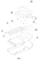
- Figure 5a is a first partially exploded schematic view of a USB device according to a second embodiment of the present invention.
- Figure 5b is a second partially exploded schematic view of the USB device according to the second embodiment of the present invention.
- FIG. 6 is a first structural schematic view of the USB device according to the second embodiment of the present invention.
- FIG. 7 is a second structural schematic view of the USB device according to the second embodiment of the present invention.
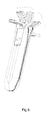
- Figure 8 is a schematic view of the USB connector in use in the USB device according to the second embodiment of the present invention.
- a USB connector 51 for connecting with a USB female comprises metal legs 11, a connecting line 12 and a substrate 13.
- One end of the metal legs 11 connects with one end of the connecting line 12.
- Aother end of the connecting line 12 is used to connect with a PCB.
- the metal legs 11 are formed on a surface of the substrate 13.
- the connecting line 12 is fixed to the surface of the substrate 13.
- the thickness of the USB connector depends mainly on the thickness of the substrate 13. As long as the thickness of the substrate 13 meets a requirement of inserting the USB connector into the USB female, the thickness of the USB connector and further, the thickness of the USB device are reduced without compromising the function of the USB connector.
- the thickness of the USB device according to the present invention is greatly reduced, making the USB device smaller and easy to carry, which not only meets the people's requirement for tiny and compact electronic products, but also improves the practicality and aesthetics of the USB device.
- the thickness of the substrate 13 is more than 2.45 mm, it may be difficult to insert the USB connector into the USB female.
- the thickness of the substrate 13 is less than 2.2 mm, a gap between the USB connector and the USB female may be too large after insertion of the USB connector into the USB female. As a result, the stability of connection between the USB connector and the USB female is reduced. Therefore, the thickness of the substrate 13 is preferably in the range of 2.2 mm to 2.45 mm.
- the metal legs 11 may be fixed to the surface of the substrate 13 by means of In Mold Decoration (IMD) molding or hot-inserting. Furthermore, in order to improve the connecting strength of the metal legs 11, slots may be set on the surface of the substrate 13 and the metal legs 11 are embedded in the surface of the substrate 13 so as to integrate with the substrate 13. Alternatively, the metal legs 11 may be formed on the surface of the substrate 13 by corrosion methods. For example, the metal legs 11 are formed by copper exposure on the surface of the substrate 13.
- IMD In Mold Decoration
- slots may be set on the surface of the substrate 13 and the metal legs 11 are embedded in the surface of the substrate 13 so as to integrate with the substrate 13.
- the metal legs 11 may be formed on the surface of the substrate 13 by corrosion methods. For example, the metal legs 11 are formed by copper exposure on the surface of the substrate 13.
- the surface of the metal legs 11 is not below the surface of the substrate 13.
- the metal legs 11 exceed the surface of the substrate 13 by a height of more than 0.2 mm, it may be difficult to insert the USB connector into the USB female. So, the metal legs exceed the surface of the substrate 13 by the height of between 0 and 0.2 mm.
- the surface of the metal legs 11 is plated with gold or silver to prevent the metal legs 11 from being oxidized by the contaminants in the air and prevent the metal legs 11 from being eroded when a user contacts them.
- the connecting line 12 also includes a ground terminal 121 for connecting with the ground of the PCB.
- a metal layer 14 is provided at other surface of the substrate 13 opposite to the metal legs 11. The metal layer 14 connects with the ground terminal 121 through a metal sheet 15 to realize the ESD protection.
- the metal layer 14 may be a layer of stainless steel so as to improve its anticorrosion, thereby prolonging the life of the USB connector.
- the metal sheet 15 extends through the substrate 13 so that one end of the metal sheet 15 connects with the ground terminal 121 of the connecting line 12 and the other end connects with the metal layer 14.
- the metal sheet 15 is invisible from the outside of the assembled USB connector, thereby improving the aesthetics of the USB connector.
- the metal layer 14 may be fixed to the substrate 13 by means of ultrasonic welding, bonding or other methods so that a good contact between the metal layer 14 and the metal sheet 15 is ensured.
- a retainer 16 for the connecting line is provided to cover the connecting line 12.
- the retainer 16 for the connecting line fixes the connecting line 12 onto the substrate 13.
- the retainer 16 for the connecting line may be made of plastic or hot-melt rubber by means of injection molding. The heated plastic or hot-melt rubber is filled into the gap between the connecting line 12 and the substrate 13 and forms the retainer 16 for the connecting line after cooling.
- a fool-proof structure 17 is provided on the surface of the substrate 13 to prevent the USB connector from being inserted reversely.
- the surface with the fool-proof structure 17 is set upward so as to form a good contact between the metal legs 11 and the USB female 1, thereby preventing the USB connector from being inserted reversely into the USB female and from causing a short circuit or no function by means of the fool-proof structure 17. Since a gap is formed between the surface of the substrate 13 and the inner wall of the USB female when the substrate 13 engages with the USB female, the fool-proof structure 17 may be accommodated into the gap.
- a universal USB female may enageg with the USB connector 51 according to this embodiment.
- the fool-proof structures 17 can be disposed symmetrically or asymmetrically on the surface of the substrate 13.
- the fool-proof structures 17 are disposed symmetrically on the surface of the substrate 13 to improve the aesthetics of the USB connector and facilitate manufacturing.
- the fool-proof structures 17 may be the projections disposed on one side of the surface of the substrate 13 or symmetrically on both sides of the surface of the substrate 13.
- a rotating shaft assembly 18 is fixed to the surface of the substrate 13.
- the rotating shaft assembly 18 may be fixed to the surface of the substrate 13 by means of ultrasonic welding, bonding and so on.
- the USB connector 51 when the USB connector 51 is installed to other components by the rotating shaft assembly 18 to form a USB device such as a U-disk or a wireless network adaptor, the USB connector 51 may rotate relative to other components by means of the rotating shaft assembly 18.
- the rotating shaft assembly 18 may include a rotating shaft 181 and a rotating shaft sleeve 182.
- the rotating shaft sleeve 182 is fixed on the surface of the substrate 13 and the rotating shaft 181 may rotate in the rotating shaft sleeve 182.
- the rotating shaft 181 has a first positioning structure 1811 thereon, and the rotating shaft sleeve 182 has a second positioning structure 1821 therein.
- the first positioning structure 1811 works with the second positioning structure 1821 to realize the positioning function.
- the rotating shaft assembly 18 with the first positioning structure 1811 and the second positioning structure 1821 could realize positioning when the USB connector 51 is rotating. For example, the USB connector 51 may stop when rotating every 45° or every 90°.
- the first positioning structure 1811 and the second positioning structure 1821 may adopt the conventional positioning structure.
- the first positioning structure 1811 is elastic projections
- the second positioning structure 1821 is positioning holes or positioning grooves distributed regularly within the rotating shaft sleeve 182 according to the positioning requirements when the USB connector 51 rotates.
- the elastic projections insert into the positioning holes or the positioning grooves, thereby stopping and positioning the USB connector 51.
- the elastic projections deform under extrusion of the inner wall of the positioning holes or the positioning grooves and disengage from the positioning holes, so that the USB connector may continue to rotate in an original direction or an opposite direction.
- the rotating shaft assembly 18 may also include a rotating shaft support 183. Unlike the way in which the rotating shaft sleeve 182 is fixed on the surface of the substrate 13, the rotating shaft assembly 18 with the rotating shaft support 183 is fixed on the surface of the substrate 13 by the rotating shaft support 183.
- the rotating shaft assemble provided with a rotating shaft support is fixed on the surface of the substrate in the following way: the rotating shaft support 183 is nested in the surface of the substrate 13, a portion of the rotating shaft support 183 which comes into contact with the surface of the substrate 13 is fixedly connected, a first support hole 1831 and a second support hole 1832 are provided at either side of the rotating shaft support 183 respectively, the other end of the connecting line 12 passes through the first support hole 1831 to connect with the PCB; the rotating shaft sleeve 182 passes through the second support hole 1832.
- the USB connector has been installed to other components to form a USB device, the USB connector may rotate clockwise or anti-clockwise relative to other components by means of the rotating shaft assembly 18.
- the connecting line 12 twists or untwists like a fried-dough-twist.
- the rotating shaft sleeve 182 includes a first sleeve part 1822, a second sleeve part 1823 and a elastic part 1824.
- the first sleeve part 1822 has a through hole thereon.
- the second sleeve part 1823 has a cavity 28231 therein and a hole 18232 formed in the side wall of the second sleeve part 1823.
- the elastic part 1824 may be a spring and so on.
- the rotating shaft 181 comprises a elastic suqare head 1811 and a trailing end 1812 which connects with the elastic square head. The trailing end 1812 passes through the first sleeve part and cooperates with the second sleeve part 1823 of the rotating shaft sleeve 182 to press the elastic part 1824.
- the elastic deformation of the elastic part 1824 resumes so that the elastic square head 1811 is ejected out of the hole 18232 of the side wall of the second sleeve part.
- a USB device such as a U-disk or a wireless network adaptor and so on comprises the USB connector 51 as described in the first embodiment, a housing 52 and a PCB.
- the same parts as those in the first embodiment are indicated by the same reference numerals as those in the first embodiment.
- the USB connector 51 comprises metal legs 11, a connecting line 12, a substrate 13 and a rotating shaft assembly 18. One end of the metal legs 11 connects with one end of the connecting line 12. The metal legs 11 are formed on the surface of the substrate 13.
- the rotating shaft assembly 18 is fixed to the surface of the substrate 13.
- the USB connector is installed at the end of the housing 52 by the rotating shaft assembly 18.
- the PCB is disposed inside the cavity of the housing and the end of the PCB connects with other end of the connecting line 12.
- a receptacle 521 for accommodating the USB connector is provided in the surface of the housing.
- the housing generally includes a first housing 522 and a second housing 523.
- the first and second housings join together to form a cavity in which the PCB is disposed.
- each of both ends of the USB connector is fitted into one corresponding hole which is provided at either side of one end of the first housing.
- the USB connector is thus installed at one end of the first housing by the rotating shaft assembly 18; then the first housing is covered with the second housing to form the USB device.
- the USB connector may rotate with respect to the housing and ensures the continuity of the connecting line 12.
- the rotating shaft assembly 18 comprises a rotating shaft sleeve and a rotating shaft, the rotating shaft may rotate in the shaft sleeve, the rotating shaft sleeve is fixed to the surface of the substrate, and each of both ends of the rotating shaft is fitted into the corresponding hole of either side of the one end of the first housing; alternatively, as shown in figs.
- the rotating shaft assembly 18 comprises a rotating shaft sleeve 182, a rotating shaft 181 and a rotating shaft support 183; the rotating shaft support 183 is fixed to the surface of the substrate 13; the rotating shaft sleeve 182 passes from inside through the second support hole 1832 at one side of the rotating shaft support 183 and a hole 5221 formed at one side of the one end of the first housing; the rotating shaft 181 may rotate in the rotating shaft sleeve 182; a first supporting portion which is coaxial with the rotating shaft 181 is provided on the rotating shaft support 183, and a second supporting portion corresponding to the first supporting portion is provided at the first housing; the first supporting portion cooperates with the second supporting portion so as to connect pivotably the USB connector with the first housing.
- the first supporting portion may be a projection 1831 protruding outward from the rotating shaft support 183, and the second supporting portion may be a hole 5222 formed at other side of the one end of the first housing, and the projection is nested into the hole.
- the first supporting portion may be a groove formed on the rotating shaft support 183, the second supporting portion may be a projection protruding inward from other side of the one end of the first housing, and the projection is nested into the groove.
- the receptacle 521 on the surface of the housing accommodates the USB connector in such a way that the metal legs face to the receptacle.
- the USB connector is accommodated into the receptacle and the metal legs face to the receptacle.
- the other surface of the substrate opposite to the metal legs exposes to the outside, thereby preventing the metal legs from being contaminated or damaged by the environment.
- the USB connector may rotate with respect to the housing in a direction or in an opposite direction so that it may rotate freely and is easy to store.
- the USB device according to the present invention eliminates the disadvantage of conventioanl USB device in which the USB connector is arranged in a line with the housing and can not be bent.
Abstract
Description
- The present application claims the priority of Chinese Patent Application No.
200810006325.5 filed on Feb. 26, 2008 - The invention relates to the field of communication, in particular to a USB (Universal Serial Bus) connector and a USB device.
- With the rapid development of communication technology, USB products play a more and more important role in people's life and work. Conventional USB products generally use special USB connectors. A special USB connector is provided at a front end of the USB products, and the USB products connect with a USB port through the USB connector.
- During the implementation of the present invention, the inventor has found that with regard to the USB products commonly available in the market, its USB port connects longitudinally with the USB body. Therefore, the length of the USB port adds to the length of the USB body which makes the USB products longer. As a result, such USB products are neither easy to carry nor up to people's standards for exquisiteness and compactness.
- The present invention provides a USB connector and a USB device. The USB connector has a reduced thickness, thereby decreasing the thickness of the USB device.
- The present invention provides a USB connector for connecting with a USB female comprising metal legs, a connecting line, a substrate and a rotating shaft assembly. One end of the metal legs connects with one end of the connecting line. The metal legs are formed on a surface of the substrate. The connecting line and the rotating shaft assembly are fixed to the surface of the substrate.
- The present invention also provides a USB device comprising a USB connector, a housing and a PCB (Printed Circuit Board) wherein:
- the USB connector comprises metal legs, a connecting line, a substrate and a rotating shaft assembly, one end of the metal legs connects with one end of the connecting line, the metal legs are formed on a surface of the substrate, the connecting line is fixed to the surface of the substrate, the rotating shaft assembly is fixed to the surface of the substrate; and the USB connector is installed at an end of the housing by the rotating shaft assembly;
- the PCB is disposed inside the cavity of the housing and an end of the PCB connects with another end of the connecting line; and
- a receptacle for accommodating the USB connector is provided on a surface of the housing.
- According to the USB connector and the USB device of the present invention, the metal legs are formed on the surface of the substrate so as to ensure the connecting strength of the metal legs. Since the size of the USB connector depends mainly on the substrate and as long as the thickness meets a requirement of inserting the USB connector into the USB female, the thickness of the USB connector and further, the thickness of the USB device are reduced without compromising the function of the USB connector. Compared with the conventional USB products, the thickness of the USB device according to the present invention is greatly reduced so that the USB device becomes smaller and easy to carry. It not only meets the people's requirement for exquisite and compact electronic products, but also improves the practicality and aesthetics of the USB device.
-
Figure 1 is an exploded schematic view of a USB connector according to a first embodiment of the present invention; -
Figure 2a is a first structural schematic view of the USB connector according to the first embodiment of the present invention; -
Figure 2b is a second structural schematic of the USB connector according to the first embodiment of the present invention; -
Figure 3 is an exploded schematic of a rotating shaft assembly shown inFigure 1 ; -
Figure 4 is a structural schematic of the rotating shaft assembly shown inFigure 3 ; -
Figure 5a is a first partially exploded schematic view of a USB device according to a second embodiment of the present invention; -
Figure 5b is a second partially exploded schematic view of the USB device according to the second embodiment of the present invention; -
Figure 6 is a first structural schematic view of the USB device according to the second embodiment of the present invention; -
Figure 7 is a second structural schematic view of the USB device according to the second embodiment of the present invention; and -
Figure 8 is a schematic view of the USB connector in use in the USB device according to the second embodiment of the present invention. - The present invention is detailed as below.
- In the first embodiment, as shown in
Figure 1 , aUSB connector 51 for connecting with a USB female comprisesmetal legs 11, a connectingline 12 and asubstrate 13. One end of themetal legs 11 connects with one end of the connectingline 12. Aother end of the connectingline 12 is used to connect with a PCB. Themetal legs 11 are formed on a surface of thesubstrate 13. The connectingline 12 is fixed to the surface of thesubstrate 13. The thickness of the USB connector depends mainly on the thickness of thesubstrate 13. As long as the thickness of thesubstrate 13 meets a requirement of inserting the USB connector into the USB female, the thickness of the USB connector and further, the thickness of the USB device are reduced without compromising the function of the USB connector. Compared with the conventional USB products, the thickness of the USB device according to the present invention is greatly reduced, making the USB device smaller and easy to carry, which not only meets the people's requirement for exquisite and compact electronic products, but also improves the practicality and aesthetics of the USB device. - Furthermore, when the thickness of the
substrate 13 is more than 2.45 mm, it may be difficult to insert the USB connector into the USB female. When the thickness of thesubstrate 13 is less than 2.2 mm, a gap between the USB connector and the USB female may be too large after insertion of the USB connector into the USB female. As a result, the stability of connection between the USB connector and the USB female is reduced. Therefore, the thickness of thesubstrate 13 is preferably in the range of 2.2 mm to 2.45 mm. - The
metal legs 11 may be fixed to the surface of thesubstrate 13 by means of In Mold Decoration (IMD) molding or hot-inserting. Furthermore, in order to improve the connecting strength of themetal legs 11, slots may be set on the surface of thesubstrate 13 and themetal legs 11 are embedded in the surface of thesubstrate 13 so as to integrate with thesubstrate 13. Alternatively, themetal legs 11 may be formed on the surface of thesubstrate 13 by corrosion methods. For example, themetal legs 11 are formed by copper exposure on the surface of thesubstrate 13. - Further, in order to ensure the electrical connecting performance between the metal legs and the USB female, the surface of the
metal legs 11 is not below the surface of thesubstrate 13. However, when themetal legs 11 exceed the surface of thesubstrate 13 by a height of more than 0.2 mm, it may be difficult to insert the USB connector into the USB female. So, the metal legs exceed the surface of thesubstrate 13 by the height of between 0 and 0.2 mm. - Further, in order to prolong the life of the USB connector, the surface of the
metal legs 11 is plated with gold or silver to prevent themetal legs 11 from being oxidized by the contaminants in the air and prevent themetal legs 11 from being eroded when a user contacts them. - Further, in order to improve the Electro-Static Discharge (ESD) protection for the USB connector, the connecting
line 12 also includes aground terminal 121 for connecting with the ground of the PCB. Ametal layer 14 is provided at other surface of thesubstrate 13 opposite to themetal legs 11. Themetal layer 14 connects with theground terminal 121 through ametal sheet 15 to realize the ESD protection. Further, themetal layer 14 may be a layer of stainless steel so as to improve its anticorrosion, thereby prolonging the life of the USB connector. Further, themetal sheet 15 extends through thesubstrate 13 so that one end of themetal sheet 15 connects with theground terminal 121 of the connectingline 12 and the other end connects with themetal layer 14. Thus, themetal sheet 15 is invisible from the outside of the assembled USB connector, thereby improving the aesthetics of the USB connector. Themetal layer 14 may be fixed to thesubstrate 13 by means of ultrasonic welding, bonding or other methods so that a good contact between themetal layer 14 and themetal sheet 15 is ensured. - Further, in order to enhance the stability of the USB connector, a
retainer 16 for the connecting line is provided to cover the connectingline 12. Theretainer 16 for the connecting line fixes the connectingline 12 onto thesubstrate 13. Theretainer 16 for the connecting line may be made of plastic or hot-melt rubber by means of injection molding. The heated plastic or hot-melt rubber is filled into the gap between the connectingline 12 and thesubstrate 13 and forms theretainer 16 for the connecting line after cooling. - Further, in order to improve the practicability of the USB connector, a fool-
proof structure 17 is provided on the surface of thesubstrate 13 to prevent the USB connector from being inserted reversely. When the user inserts theUSB connector 51 into the USB female, the surface with the fool-proof structure 17 is set upward so as to form a good contact between themetal legs 11 and the USB female 1, thereby preventing the USB connector from being inserted reversely into the USB female and from causing a short circuit or no function by means of the fool-proof structure 17. Since a gap is formed between the surface of thesubstrate 13 and the inner wall of the USB female when thesubstrate 13 engages with the USB female, the fool-proof structure 17 may be accommodated into the gap. Thus, a universal USB female may enageg with theUSB connector 51 according to this embodiment. In addition, the fool-proof structures 17 can be disposed symmetrically or asymmetrically on the surface of thesubstrate 13. Preferably, the fool-proof structures 17 are disposed symmetrically on the surface of thesubstrate 13 to improve the aesthetics of the USB connector and facilitate manufacturing. Alternatively, the fool-proof structures 17 may be the projections disposed on one side of the surface of thesubstrate 13 or symmetrically on both sides of the surface of thesubstrate 13. - Further, in order to ensure flexibility when the USB connector is in use, as shown in
Figure 2a , arotating shaft assembly 18 is fixed to the surface of thesubstrate 13. Therotating shaft assembly 18 may be fixed to the surface of thesubstrate 13 by means of ultrasonic welding, bonding and so on. SeeFigures 5a and5b , when theUSB connector 51 is installed to other components by therotating shaft assembly 18 to form a USB device such as a U-disk or a wireless network adaptor, theUSB connector 51 may rotate relative to other components by means of therotating shaft assembly 18. Further, seeFigures 3 and 4 , the rotatingshaft assembly 18 may include arotating shaft 181 and arotating shaft sleeve 182. Therotating shaft sleeve 182 is fixed on the surface of thesubstrate 13 and therotating shaft 181 may rotate in therotating shaft sleeve 182. Therotating shaft 181 has afirst positioning structure 1811 thereon, and therotating shaft sleeve 182 has asecond positioning structure 1821 therein. Thefirst positioning structure 1811 works with thesecond positioning structure 1821 to realize the positioning function. Therotating shaft assembly 18 with thefirst positioning structure 1811 and thesecond positioning structure 1821 could realize positioning when theUSB connector 51 is rotating. For example, theUSB connector 51 may stop when rotating every 45° or every 90°. Thefirst positioning structure 1811 and thesecond positioning structure 1821 may adopt the conventional positioning structure. For example, thefirst positioning structure 1811 is elastic projections, and thesecond positioning structure 1821 is positioning holes or positioning grooves distributed regularly within therotating shaft sleeve 182 according to the positioning requirements when theUSB connector 51 rotates. When therotating shaft 181 rotates relative to therotating shaft sleeve 182 and thefirst location structure 1811 meets thesecond location structure 1821, the elastic projections insert into the positioning holes or the positioning grooves, thereby stopping and positioning theUSB connector 51. When a force for continuously rotating theUSB connector 51 has effect on theUSB connector 51, the elastic projections deform under extrusion of the inner wall of the positioning holes or the positioning grooves and disengage from the positioning holes, so that the USB connector may continue to rotate in an original direction or an opposite direction. - In order to facilitate mounting the
USB connector 51 to other components to form the USB device, the rotatingshaft assembly 18 may also include arotating shaft support 183. Unlike the way in which therotating shaft sleeve 182 is fixed on the surface of thesubstrate 13, the rotatingshaft assembly 18 with therotating shaft support 183 is fixed on the surface of thesubstrate 13 by therotating shaft support 183. As shown infigures 2a and 2b , the rotating shaft assemble provided with a rotating shaft support is fixed on the surface of the substrate in the following way: the rotatingshaft support 183 is nested in the surface of thesubstrate 13, a portion of therotating shaft support 183 which comes into contact with the surface of thesubstrate 13 is fixedly connected, afirst support hole 1831 and asecond support hole 1832 are provided at either side of therotating shaft support 183 respectively, the other end of the connectingline 12 passes through thefirst support hole 1831 to connect with the PCB; therotating shaft sleeve 182 passes through thesecond support hole 1832. As shown infigure 1 , five wires are twisted together to form the connectingline 12, one end of the five wires connects with themetal legs 11 and the other end passes through thefirst support hole 1831. As shown infigure 6 , the USB connector has been installed to other components to form a USB device, the USB connector may rotate clockwise or anti-clockwise relative to other components by means of therotating shaft assembly 18. During rotation, the connectingline 12 twists or untwists like a fried-dough-twist. Further, therotating shaft sleeve 182 includes afirst sleeve part 1822, asecond sleeve part 1823 and aelastic part 1824. Thefirst sleeve part 1822 has a through hole thereon. Thesecond sleeve part 1823 has a cavity 28231 therein and ahole 18232 formed in the side wall of thesecond sleeve part 1823. Theelastic part 1824 may be a spring and so on. Therotating shaft 181 comprises aelastic suqare head 1811 and a trailingend 1812 which connects with the elastic square head. The trailingend 1812 passes through the first sleeve part and cooperates with thesecond sleeve part 1823 of therotating shaft sleeve 182 to press theelastic part 1824. After the trailingend 1812 is fitted into thecavity 18231 of the second sleeve part, the elastic deformation of theelastic part 1824 resumes so that the elasticsquare head 1811 is ejected out of thehole 18232 of the side wall of the second sleeve part. - In the second embodiment, as shown in
Figures 5a ,Fig 5b and6 , a USB device such as a U-disk or a wireless network adaptor and so on comprises theUSB connector 51 as described in the first embodiment, ahousing 52 and a PCB. The same parts as those in the first embodiment are indicated by the same reference numerals as those in the first embodiment. TheUSB connector 51 comprisesmetal legs 11, a connectingline 12, asubstrate 13 and arotating shaft assembly 18. One end of themetal legs 11 connects with one end of the connectingline 12. Themetal legs 11 are formed on the surface of thesubstrate 13. Therotating shaft assembly 18 is fixed to the surface of thesubstrate 13. The USB connector is installed at the end of thehousing 52 by therotating shaft assembly 18. The PCB is disposed inside the cavity of the housing and the end of the PCB connects with other end of the connectingline 12. Areceptacle 521 for accommodating the USB connector is provided in the surface of the housing. - In order to facilitate assembling, the housing generally includes a
first housing 522 and asecond housing 523. The first and second housings join together to form a cavity in which the PCB is disposed. When assembled, each of both ends of the USB connector is fitted into one corresponding hole which is provided at either side of one end of the first housing. The USB connector is thus installed at one end of the first housing by therotating shaft assembly 18; then the first housing is covered with the second housing to form the USB device. The USB connector may rotate with respect to the housing and ensures the continuity of the connectingline 12. Mounting the USB connector at one end of the first housing by therotating shaft assembly 18 may be implemented in the following ways: the rotating shaft assembly comprises a rotating shaft sleeve and a rotating shaft, the rotating shaft may rotate in the shaft sleeve, the rotating shaft sleeve is fixed to the surface of the substrate, and each of both ends of the rotating shaft is fitted into the corresponding hole of either side of the one end of the first housing; alternatively, as shown infigs. 5a and5b , the rotatingshaft assembly 18 comprises arotating shaft sleeve 182, arotating shaft 181 and arotating shaft support 183; therotating shaft support 183 is fixed to the surface of thesubstrate 13; therotating shaft sleeve 182 passes from inside through thesecond support hole 1832 at one side of therotating shaft support 183 and ahole 5221 formed at one side of the one end of the first housing; therotating shaft 181 may rotate in therotating shaft sleeve 182; a first supporting portion which is coaxial with therotating shaft 181 is provided on therotating shaft support 183, and a second supporting portion corresponding to the first supporting portion is provided at the first housing; the first supporting portion cooperates with the second supporting portion so as to connect pivotably the USB connector with the first housing. The first supporting portion may be aprojection 1831 protruding outward from therotating shaft support 183, and the second supporting portion may be ahole 5222 formed at other side of the one end of the first housing, and the projection is nested into the hole. Alternatively, the first supporting portion may be a groove formed on therotating shaft support 183, the second supporting portion may be a projection protruding inward from other side of the one end of the first housing, and the projection is nested into the groove. - The
receptacle 521 on the surface of the housing accommodates the USB connector in such a way that the metal legs face to the receptacle. Thus, when the USB device is unused, the USB connector is accommodated into the receptacle and the metal legs face to the receptacle. Viewed from outside of the USB device, only the other surface of the substrate opposite to the metal legs exposes to the outside, thereby preventing the metal legs from being contaminated or damaged by the environment. - Further, as shown in
Figure 7 , from the perspective of aesthetics and psychology, there is a smooth transition between an outside surface of the USB connector and an outside surface of the housing when the USB connector is accommodated in the receptacle. Thus, when the USB device is unused, the USB connector and the housing appear to have the same surface so that the appearance of the USB device is aesthetic, simple and smooth, thereby meeting the user's requirements for exquisite products. - As shown in
Figure 8 , in practice, the USB connector may rotate with respect to the housing in a direction or in an opposite direction so that it may rotate freely and is easy to store. The USB device according to the present invention eliminates the disadvantage of conventioanl USB device in which the USB connector is arranged in a line with the housing and can not be bent. - The description above is merely a special embodiment of the present invention. It is noted that it is possible for a person skilled in the art to make various modifications and variations without departing from the principles of the present invention and those modifications and variations will fall within the scope of the present invention.
Claims (15)
- A USB connector for connecting with a USB female comprising metal legs, a connecting line, a substrate and a rotating shaft assembly, wherein one end of the metal legs connects with one end of the connecting line, the metal legs are formed on a surface of the substrate, the connecting line is fixed to the surface of the substrate, and said rotating shaft assembly includes a rotating shaft and a rotating shaft sleeve, the rotating shaft sleeve is fixed on the surface of the substrate, and the rotating shaft is disposed in the rotating shaft sleeve and is capable of rotating relative to the rotating shaft sleeve.
- The USB connector according to claim 1, wherein the rotating shaft has a first positioning structure thereon, the rotating shaft sleeve has a second positioning structure therein, and the first positioning structure works with the second positioning structure to realize the positioning function.
- The USB connector according to claim 2, wherein the rotating shaft assembly further comprises a rotating shaft support; a first support hole and a second support hole are provided at either side of the rotating shaft support respectively; another end of the connecting line passes through the first support hole and the rotating shaft sleeve passes through the second support hole.
- A USB device comprising a USB connector, a housing and a PCB, wherein:the USB connector comprises metal legs, a connecting line, a substrate and a rotating shaft assembly; one end of the metal legs connects with one end of the connecting line, the metal legs are formed on a surface of the substrate, the connecting line is fixed to the surface of the substrate, said rotating shaft assembly comprises a rotating shaft and a rotating shaft sleeve, the rotating shaft sleeve is fixed on the surface of the substrate, the rotating shaft is disposed in the rotating shaft sleeve and capable of rotating relative to the rotating shaft sleeve; and the USB connector is installed at an end of the housing by the rotating shaft assembly;the PCB is disposed inside a cavity of the housing and an end of the PCB connects with other end of the connecting line; anda receptacle for accommodating the USB connector is provided on a surface of the housing.
- The USB device according to claim 4, wherein the receptacle accommodates the USB connector in such a way that the metal legs face to the receptacle.
- The USB device according to claim 4, wherein the connecting line further comprises a ground terminal for connecting with a ground of the PCB, a metal layer is provided at other surface of the substrate opposite to the metal legs, and the metal layer connects with the ground terminal through a metal sheet.
- The USB device according to claim 4, wherein there is a smooth transition between an outside surface of the USB connector and an outside surface of the housing when the USB connector is accommodated in the receptacle.
- The USB device according to claim 4, wherein the connecting line further comprises a ground terminal, a metal layer is provided at other surface of the substrate opposite to the metal legs, and the metal layer connects with the ground terminal through a metal sheet.
- The USB device according to claim 8, wherein the surface of the metal legs is not below the surface of the substrate, and the metal legs exceed the surface of the substrate by a height of between 0 and 0.2 mm.
- The USB device according to claim 4, wherein the USB connector further comprises a retainer for the connecting line which is provided to cover the connecting line.
- The USB device according to claim 4, wherein the USB connector further comprises a fool-proof structure provided on the surface of the substrate to prevent the USB connector from being inserted reversely.
- The USB device according to claim 4, wherein the rotating shaft has a first positioning structure thereon, the rotating shaft sleeve has a second positioning structure therein, and the first positioning structure works with the second positioning structure to realize the positioning function.
- The USB device according to claim 12, wherein the rotating shaft assembly further comprises a rotating shaft support, a first support hole and a second support hole are provided at either side of the rotating shaft support respectively, other end of the connecting line passes through the first support hole and the rotating shaft sleeve passes through the second support hole.
- The USB device according to claim 13, wherein the rotating shaft sleeve comprises a first sleeve part, a second sleeve part and a elastic part, and the rotating shaft comprises a elastic square head; the second sleeve part has a cavity therein and a hole formed in its side wall, the second positioning structure is formed on the first sleeve part, and a trailing end of the rotating shaft cooperates with the second sleeve part to press the elastic part, and the elastic deformation of the elastic part resumes after the trailing end is fitted into the cavity of the second sleeve part so that the elastic square head is ejected out of the hole in the side wall of the second sleeve part.
- The USB device according to claim 4, wherein each of both ends of the USB connector is fitted into one corresponding hole which is provided at either side of one end of a first housing of the housing, the USB connector is installed at one end of the first housing by the rotating shaft assembly, and the first housing is covered with a second housing.
Priority Applications (3)
| Application Number | Priority Date | Filing Date | Title |
|---|---|---|---|
| EP10150216.9A EP2178179B1 (en) | 2008-02-26 | 2009-02-19 | USB connector and USB device |
| EP11187985A EP2416456A3 (en) | 2008-02-26 | 2009-02-19 | USB Device |
| EP11154365.8A EP2315323B1 (en) | 2008-02-26 | 2009-02-19 | USB connector and USB device |
Applications Claiming Priority (1)
| Application Number | Priority Date | Filing Date | Title |
|---|---|---|---|
| CN2008100063255A CN101242047B (en) | 2008-02-26 | 2008-02-26 | USB connection member and USB device |
Related Child Applications (1)
| Application Number | Title | Priority Date | Filing Date |
|---|---|---|---|
| EP10150216.9 Division-Into | 2010-01-07 |
Publications (3)
| Publication Number | Publication Date |
|---|---|
| EP2096724A1 true EP2096724A1 (en) | 2009-09-02 |
| EP2096724B1 EP2096724B1 (en) | 2010-02-17 |
| EP2096724B8 EP2096724B8 (en) | 2010-04-14 |
Family
ID=39933348
Family Applications (4)
| Application Number | Title | Priority Date | Filing Date |
|---|---|---|---|
| EP09153153A Active EP2096724B8 (en) | 2008-02-26 | 2009-02-19 | USB connector and USB device |
| EP11187985A Withdrawn EP2416456A3 (en) | 2008-02-26 | 2009-02-19 | USB Device |
| EP10150216.9A Active EP2178179B1 (en) | 2008-02-26 | 2009-02-19 | USB connector and USB device |
| EP11154365.8A Active EP2315323B1 (en) | 2008-02-26 | 2009-02-19 | USB connector and USB device |
Family Applications After (3)
| Application Number | Title | Priority Date | Filing Date |
|---|---|---|---|
| EP11187985A Withdrawn EP2416456A3 (en) | 2008-02-26 | 2009-02-19 | USB Device |
| EP10150216.9A Active EP2178179B1 (en) | 2008-02-26 | 2009-02-19 | USB connector and USB device |
| EP11154365.8A Active EP2315323B1 (en) | 2008-02-26 | 2009-02-19 | USB connector and USB device |
Country Status (15)
| Country | Link |
|---|---|
| US (5) | US7828599B2 (en) |
| EP (4) | EP2096724B8 (en) |
| JP (2) | JP5066263B2 (en) |
| KR (1) | KR101175218B1 (en) |
| CN (1) | CN101242047B (en) |
| AT (1) | ATE458291T1 (en) |
| AU (1) | AU2008351654B2 (en) |
| BR (1) | BRPI0821655B1 (en) |
| CA (2) | CA2654989C (en) |
| DE (3) | DE202009018560U1 (en) |
| ES (3) | ES2420986T3 (en) |
| HK (1) | HK1140859A1 (en) |
| RU (1) | RU2444821C2 (en) |
| SG (1) | SG174084A1 (en) |
| WO (1) | WO2009105953A1 (en) |
Cited By (6)
| Publication number | Priority date | Publication date | Assignee | Title |
|---|---|---|---|---|
| WO2012014157A1 (en) * | 2010-07-26 | 2012-02-02 | Option | Usb stick with hingedly mounted usb connector, rotatable to multiple use positions |
| EP2475051A1 (en) * | 2009-09-18 | 2012-07-11 | Huawei Device Co., Ltd. | Wireless terminal device |
| EP2544517A1 (en) * | 2010-08-12 | 2013-01-09 | Huawei Device Co., Ltd. | User device |
| EP2562889A1 (en) * | 2010-11-05 | 2013-02-27 | Huawei Device Co., Ltd. | Wireless modem |
| US8821175B2 (en) | 2010-07-12 | 2014-09-02 | Huawei Device Co., Ltd. | USB connector, USB housing, and wireless modem |
| EP2493034B1 (en) * | 2011-01-07 | 2016-12-07 | ZTE Corporation | Universal serial bus (usb) interface and data product thereof |
Families Citing this family (47)
| Publication number | Priority date | Publication date | Assignee | Title |
|---|---|---|---|---|
| CN101242047B (en) | 2008-02-26 | 2010-06-09 | 华为终端有限公司 | USB connection member and USB device |
| CN101854782B (en) * | 2009-04-01 | 2012-06-27 | 华东科技股份有限公司 | Attached memory device |
| JP2010251319A (en) | 2009-04-15 | 2010-11-04 | Chou Hsien Tsai | Socket structure with duplex electrical connection |
| CN101609954B (en) * | 2009-07-16 | 2011-04-06 | 中兴通讯股份有限公司 | Dual-rotation shaft rotary wireless network card |
| CN201550379U (en) * | 2009-11-05 | 2010-08-11 | 华为终端有限公司 | Rotary shaft, digital equipment and universal series bus USB equipment |
| CN201562778U (en) * | 2009-11-19 | 2010-08-25 | 华为终端有限公司 | Electronic equipment provided with plug |
| CN101859940B (en) * | 2010-04-29 | 2012-10-17 | 华为终端有限公司 | Plug and electronic equipment provided with same |
| EP2577813B1 (en) | 2010-05-28 | 2020-01-22 | Apple Inc. | Dual orientation connector with external contacts |
| CN201718153U (en) * | 2010-06-11 | 2011-01-19 | 华为终端有限公司 | Rotary data card |
| US8125774B2 (en) * | 2010-06-14 | 2012-02-28 | Share Memories, Llc | Portable keepsake storage device with a pivoting sleeve and USB flash drive |
| CN103069654A (en) | 2010-06-18 | 2013-04-24 | 苹果公司 | Dual orientation connector with side contacts |
| CN103081253B (en) | 2010-06-21 | 2015-10-21 | 苹果公司 | Plug-in connector and socket connector |
| CN103004035A (en) | 2010-06-21 | 2013-03-27 | 苹果公司 | External contact plug connector |
| US8267704B2 (en) * | 2011-02-01 | 2012-09-18 | Transcend Information, Inc. | Connector module capable of protecting conductive resilient components thereof |
| CN102185233B (en) * | 2011-02-22 | 2014-09-10 | 中兴通讯股份有限公司 | Rotatable USB (Universal Serial Bus) interface equipment |
| KR20120124281A (en) | 2011-05-03 | 2012-11-13 | 주식회사 팬택 | USB connector |
| US8651874B2 (en) * | 2011-05-04 | 2014-02-18 | YFC-Boneagel Electric Co., Ltd. | Transmission line with rotatable connector |
| CN202150611U (en) * | 2011-06-30 | 2012-02-22 | 广东明家科技股份有限公司 | Rotating plug |
| TWM428407U (en) * | 2011-08-24 | 2012-05-01 | Hon Hai Prec Ind Co Ltd | USB device |
| US8708745B2 (en) | 2011-11-07 | 2014-04-29 | Apple Inc. | Dual orientation electronic connector |
| US9112327B2 (en) | 2011-11-30 | 2015-08-18 | Apple Inc. | Audio/video connector for an electronic device |
| US8690600B1 (en) * | 2011-12-10 | 2014-04-08 | Giorgio Zeolla | Electronic device shield and connector case |
| DE102011089025B4 (en) | 2011-12-19 | 2018-09-20 | Te Connectivity Germany Gmbh | USB socket and method for its manufacture |
| CN103209558B (en) * | 2012-01-13 | 2016-02-03 | 国基电子(上海)有限公司 | USB device and USB connector |
| KR101327601B1 (en) * | 2012-02-27 | 2013-11-12 | 주식회사 팬택 | Universal Serial Bus Device |
| US8651884B1 (en) | 2012-04-10 | 2014-02-18 | Google Inc. | Ejectable memory card tray in a universal serial bus (USB) connector |
| CN202736489U (en) * | 2012-04-16 | 2013-02-13 | 中兴通讯股份有限公司 | Wireless communication terminal |
| TWI446653B (en) * | 2012-05-21 | 2014-07-21 | Wistron Corp | Electronic device and connecting component |
| TWM450094U (en) * | 2012-08-31 | 2013-04-01 | Molex Taiwan Ltd | Plug connector, electrically-connecting device and electronic device |
| US9093803B2 (en) | 2012-09-07 | 2015-07-28 | Apple Inc. | Plug connector |
| US9160129B2 (en) * | 2012-09-11 | 2015-10-13 | Apple Inc. | Connectors and methods for manufacturing connectors |
| US9059531B2 (en) * | 2012-09-11 | 2015-06-16 | Apple Inc. | Connectors and methods for manufacturing connectors |
| US9054477B2 (en) | 2012-09-11 | 2015-06-09 | Apple Inc. | Connectors and methods for manufacturing connectors |
| CN103730799B (en) * | 2012-10-15 | 2016-06-08 | 富士康(昆山)电脑接插件有限公司 | Combined-type adapter plug |
| US9325097B2 (en) | 2012-11-16 | 2016-04-26 | Apple Inc. | Connector contacts with thermally conductive polymer |
| US20140206209A1 (en) | 2013-01-24 | 2014-07-24 | Apple Inc. | Reversible usb connector |
| USD735178S1 (en) * | 2013-03-04 | 2015-07-28 | Lg Electronics Inc. | Data cable terminal for mobile phones |
| CN203277925U (en) * | 2013-04-25 | 2013-11-06 | 鸿富锦精密工业(深圳)有限公司 | Data product having USB connector |
| TWI500224B (en) * | 2013-07-16 | 2015-09-11 | Phihong Technology Co Ltd | Connector integrating device |
| US8979549B2 (en) * | 2013-08-08 | 2015-03-17 | Kuei-Yang Lin | Rotating plug |
| TWM484831U (en) * | 2014-03-27 | 2014-08-21 | Phison Electronics Corp | Connector and storage device using the same |
| MX364969B (en) * | 2014-09-10 | 2019-05-16 | Micro Motion Inc | An enhanced safety serial bus connector. |
| TWM501628U (en) * | 2014-12-19 | 2015-05-21 | 威剛科技股份有限公司 | Removable storage device |
| TWM537293U (en) * | 2016-09-07 | 2017-02-21 | 金士頓數位股份有限公司 | Portable data transmitting device |
| CN107196093A (en) * | 2017-07-11 | 2017-09-22 | 北京合力电气传动控制技术有限责任公司 | Pressure contact connector |
| USD891433S1 (en) | 2018-11-04 | 2020-07-28 | Kien Hoe Daniel Chin | USB adapter apparatus |
| USD885391S1 (en) | 2018-11-04 | 2020-05-26 | Kien Hoe Daniel Chin | USB adapter apparatus |
Citations (6)
| Publication number | Priority date | Publication date | Assignee | Title |
|---|---|---|---|---|
| US6544075B1 (en) * | 2002-04-24 | 2003-04-08 | Accton Technology Corporation | Wireless adapter |
| US20040048494A1 (en) * | 2002-09-10 | 2004-03-11 | Wistron Neweb Corporation | Electrical adapter with a foldable housing cross-reference to related application |
| US20040215966A1 (en) * | 2003-04-28 | 2004-10-28 | Rainbow Technologies, Inc. | Bending USB token |
| US20050070138A1 (en) * | 2003-09-11 | 2005-03-31 | Super Talent Electronics Inc. | Slim USB Plug and Flash-Memory Card with Supporting Underside Ribs Engaging Socket Springs |
| US20060223369A1 (en) * | 2005-04-01 | 2006-10-05 | Bo Zheng | Device with hinged USB port |
| US7234963B1 (en) * | 2006-11-08 | 2007-06-26 | Kui-Hsien Huang | USB connector with orientation adjustment |
Family Cites Families (94)
| Publication number | Priority date | Publication date | Assignee | Title |
|---|---|---|---|---|
| US665508A (en) * | 1900-08-28 | 1901-01-08 | Abbie M Chapin | Puzzle. |
| JPH0394800U (en) * | 1990-01-17 | 1991-09-26 | ||
| TW218938B (en) * | 1993-04-12 | 1994-01-11 | Whitaker Corp | Electrical connector assembly |
| FR2730328B1 (en) | 1995-02-03 | 1997-04-04 | Connectors Pontarlier | CONNECTOR FOR MICROCIRCUIT CARD READING APPARATUS AND MICROCIRCUIT CARD READING APPARATUS INCLUDING SAME |
| US5658170A (en) * | 1995-09-26 | 1997-08-19 | Hon Hai Precision Ind. Co., Ltd. | Cable connector assembly |
| US5941733A (en) * | 1996-08-31 | 1999-08-24 | Hon Hai Precision Ind. Co., Ltd. | Universal serial bus plug connector |
| US6086430A (en) * | 1997-02-27 | 2000-07-11 | International Business Machines Corporation | Enhanced universal serial bus |
| US5938476A (en) * | 1997-04-29 | 1999-08-17 | Hon Hai Precision Ind. Co., Ltd. | Cable connector assembly |
| US6142827A (en) * | 1998-02-04 | 2000-11-07 | Advanced Connectek Inc. | Connector casing with fluid plastics baffle |
| DE69921885T2 (en) | 1998-05-26 | 2006-02-09 | Samsung Electronics Co., Ltd., Suwon | Articulating mechanism for a portable telephone |
| TW417859U (en) * | 1999-06-15 | 2001-01-01 | Hon Hai Prec Ind Co Ltd | Electric connector of easily automatic assembling |
| CN2426262Y (en) | 1999-12-02 | 2001-04-04 | 富士康(昆山)电脑接插件有限公司 | Electric circuit board for clamp connected connector |
| DE10018020C5 (en) * | 2000-04-11 | 2014-06-05 | Zf Friedrichshafen Ag | Housing and method for its production |
| TW476456U (en) * | 2000-10-17 | 2002-02-11 | Hon Hai Prec Ind Co Ltd | Assembly of cable connector |
| KR200248046Y1 (en) * | 2001-05-14 | 2001-10-29 | (주) 엠엠씨 테크놀로지 | rotatable adapter |
| US6702620B2 (en) * | 2001-09-05 | 2004-03-09 | Intel Corporation | Dual serial ATA connector |
| JP2003077606A (en) * | 2001-09-06 | 2003-03-14 | Sharp Corp | Connector device of electronic device |
| US6744634B2 (en) * | 2001-11-23 | 2004-06-01 | Power Quotient International Co., Ltd. | Low height USB interface connecting device and a memory storage apparatus thereof |
| US6685508B2 (en) * | 2001-12-28 | 2004-02-03 | Hon Hai Precision Inc. Co., Ltd. | USB connector assembly having reduced mating height |
| CN1215750C (en) * | 2002-01-14 | 2005-08-17 | 杭州飞凤通信部品有限公司 | Articulator |
| TW519323U (en) * | 2002-01-22 | 2003-01-21 | Shu-Lan Yangli | Connector |
| CN1437089B (en) * | 2002-02-05 | 2012-01-25 | 劲永科技(苏州)有限公司 | Connector for USB interface and its memory unit |
| US6762941B2 (en) * | 2002-07-15 | 2004-07-13 | Teradyne, Inc. | Techniques for connecting a set of connecting elements using an improved latching apparatus |
| KR100440407B1 (en) * | 2002-07-19 | 2004-07-14 | 삼성전자주식회사 | Portable wireless terminal with ground connecting device using hinge module |
| KR100471150B1 (en) | 2002-07-26 | 2005-03-10 | 삼성전기주식회사 | Bus port connecting device |
| US20040033727A1 (en) * | 2002-08-16 | 2004-02-19 | Chi-Lei Kao | Plug used for connection with a USB receptacle |
| JP2004139952A (en) * | 2002-08-22 | 2004-05-13 | Seiko Instruments Inc | Electronic equipment |
| CN2569201Y (en) | 2002-09-11 | 2003-08-27 | 天瀚科技股份有限公司 | USB joint with protector |
| US6808400B2 (en) * | 2002-10-18 | 2004-10-26 | Aiptek International Inc. | USB connector structure with protection means |
| KR100542401B1 (en) | 2002-10-23 | 2006-01-11 | 한국전자통신연구원 | An Admission Control Method in Differentiated Service Networks |
| CN2583715Y (en) * | 2002-11-05 | 2003-10-29 | 黄月云 | Free steering joining pallet |
| JP3094800U (en) | 2002-12-20 | 2003-07-04 | 黄 月雲 | Free direction changeable connection device |
| US6695620B1 (en) * | 2003-02-05 | 2004-02-24 | Yea Yen Huang | Cable end connector with universal joint |
| AU2004229975A1 (en) | 2003-03-31 | 2004-10-28 | General Dynamics-C4 Systems, Inc. | Call admission control/session management based on N source to destination severity levels for IP networks |
| CN2616942Y (en) * | 2003-04-25 | 2004-05-19 | 罗秀群 | Portable USB memory |
| US20040229478A1 (en) * | 2003-05-13 | 2004-11-18 | Chen Chao Ming | Rotatory wireless USB network interface card |
| US6868630B2 (en) * | 2003-08-04 | 2005-03-22 | Paul T. Kim | Picture holding system |
| DE20312211U1 (en) * | 2003-08-07 | 2003-10-30 | Yueh Wen Hsiang | Swiveling USB plug |
| US7044802B2 (en) * | 2003-09-11 | 2006-05-16 | Super Talent Electronics, Inc. | USB flash-memory card with perimeter frame and covers that allow mounting of chips on both sides of a PCB |
| US7094074B2 (en) * | 2003-09-11 | 2006-08-22 | Super Talent Electronics, Inc. | Manufacturing methods for ultra-slim USB flash-memory card with supporting dividers or underside ribs |
| US20050156333A1 (en) * | 2003-09-11 | 2005-07-21 | Super Talent Electronics Inc. | Narrow Universal-Serial-Bus (USB) Flash-Memory Card with Straight Sides using a Ball-Grid-Array (BGA) Chip |
| US20050086389A1 (en) * | 2003-10-17 | 2005-04-21 | Phillip Chang | Wireless network adapter |
| CN2684484Y (en) | 2003-12-04 | 2005-03-09 | 黄义雄 | Improved structure for pivot of mobile telephone |
| CN2678164Y (en) | 2003-12-23 | 2005-02-09 | 英济股份有限公司 | Thin-shaped universal serial bus connector with system |
| CN2682614Y (en) | 2004-01-05 | 2005-03-02 | 英济股份有限公司 | Thin type USB pin connector having fool proof design |
| US20050181634A1 (en) * | 2004-02-12 | 2005-08-18 | International Business Machines Corp. | Personal device embedded synch connector |
| CN2692968Y (en) | 2004-03-05 | 2005-04-13 | 钜金科技有限公司 | Pivot positioning structure for cover pivoted cell phone |
| GB2412019A (en) | 2004-03-12 | 2005-09-14 | Partner Tech Corp | USB plug with ball and socket joint |
| US7152801B2 (en) * | 2004-04-16 | 2006-12-26 | Sandisk Corporation | Memory cards having two standard sets of contacts |
| US7487265B2 (en) * | 2004-04-16 | 2009-02-03 | Sandisk Corporation | Memory card with two standard sets of contacts and a hinged contact covering mechanism |
| US7674117B2 (en) * | 2004-04-19 | 2010-03-09 | Michelin Recherche Et Technique S.A. | Strain-resistant electrical connection |
| US20050282417A1 (en) * | 2004-06-18 | 2005-12-22 | Robert Tsao | USB hub |
| CN2738529Y (en) * | 2004-07-01 | 2005-11-02 | 台均科技(深圳)有限公司 | Mobile memory with rotary USB interface |
| CN1734860A (en) * | 2004-08-02 | 2006-02-15 | 台湾广登电子股份有限公司 | Adapter structure with pivoting end |
| US6948983B1 (en) * | 2004-08-10 | 2005-09-27 | Megaforce Company Limited | Slim USB male connector with anti-disorientation design |
| TWM271291U (en) | 2004-10-04 | 2005-07-21 | Inventec Multimedia & Telecom | Connector |
| TWM263724U (en) | 2004-10-06 | 2005-05-01 | Behavior Tech Computer Corp | Flash drive with storable and rotatable USB connector |
| TWI259629B (en) * | 2004-10-15 | 2006-08-01 | Tul Corp | The means for the universal serial bus hide and swing |
| CN2750525Y (en) | 2004-10-25 | 2006-01-04 | 叶明祥 | Improved structure of connector |
| US7001192B1 (en) * | 2004-11-05 | 2006-02-21 | Ming-Hsiang Yeh | Structure of connector |
| US7733770B2 (en) | 2004-11-15 | 2010-06-08 | Intel Corporation | Congestion control in a network |
| TWI268022B (en) * | 2005-01-19 | 2006-12-01 | Yue-Yun Huang | Electric connector module with conducting position-limited rotation |
| FI20050139A0 (en) | 2005-02-07 | 2005-02-07 | Nokia Corp | Distributed procedure to allow a connection |
| US7025595B1 (en) * | 2005-04-13 | 2006-04-11 | Universal Scientific Industrial Co., Ltd. | Electronic device with adjustable housings |
| CN100487983C (en) | 2005-04-13 | 2009-05-13 | 台均科技(深圳)有限公司 | USB data audio-signal multiplexing transmitting line |
| CN2777798Y (en) * | 2005-04-21 | 2006-05-03 | 台均科技(深圳)有限公司 | USE data-audio-frequency signal multiplex transmission line |
| CN2817114Y (en) * | 2005-05-12 | 2006-09-13 | 上海环达计算机科技有限公司 | Metallic shield gain USB connector |
| KR100702155B1 (en) | 2005-05-12 | 2007-04-02 | 한국과학기술연구원 | Capsule type micro-robot moving system |
| JPWO2007007817A1 (en) | 2005-07-08 | 2009-01-29 | シチズンホールディングス株式会社 | Hinge device |
| GB2428335A (en) | 2005-07-12 | 2007-01-24 | Askey Computer Corp | Electronic device capable of multi-directional rotation |
| GB2430508A (en) * | 2005-09-21 | 2007-03-28 | Power Digital Card Co Ltd | Memory card with an integral dual interface |
| CN1941715B (en) | 2005-09-30 | 2010-05-05 | 华为技术有限公司 | System, method and apparatus for controlling access network |
| KR100719319B1 (en) * | 2005-11-09 | 2007-05-18 | (주)테일러테크놀로지 | Connector of Portable Device for Multimedia |
| CN100536255C (en) * | 2005-12-09 | 2009-09-02 | 北京华旗资讯数码科技有限公司 | Electronic device with USB connector plug capable of turning and folding |
| CN101009697B (en) | 2006-01-26 | 2011-06-15 | 华为技术有限公司 | The system and method for improving the success rate and efficiency of the resource request at the service layer |
| CN100428859C (en) | 2006-02-10 | 2008-10-22 | 华为技术有限公司 | Call ready to cut-in control method and device |
| CN101064405A (en) * | 2006-04-26 | 2007-10-31 | 英属开曼群岛商麦克尼多科技股份有限公司 | Rotary type universal serial bus interface connector having spacing mechanism |
| US7128615B1 (en) * | 2006-04-26 | 2006-10-31 | Sheng-Hsin Liao | Connector assembly |
| EP1855231A1 (en) | 2006-05-09 | 2007-11-14 | Zina Lindemann | Data storage card having multiple interfaces |
| JP4667305B2 (en) * | 2006-06-15 | 2011-04-13 | 三洋電機株式会社 | Data terminal equipment |
| CN100466621C (en) | 2006-06-27 | 2009-03-04 | 中国移动通信集团公司 | Admission control system and admission control method in load supporting interface of communication network |
| GB2440041B (en) * | 2006-07-10 | 2011-08-24 | Hes Ltd | Memory devices and security systems and apparatus for use with such memory devices |
| US7410370B2 (en) * | 2006-12-29 | 2008-08-12 | Sandisk Corporation | Electrical connector with ESD grounding clip |
| CN201119193Y (en) * | 2007-05-10 | 2008-09-17 | 英群企业股份有限公司 | Electronic device with multi-directional rotary connector |
| JP3160283U (en) * | 2007-05-25 | 2010-06-24 | ワン, ユハWANG, Yuhua | Bluetooth headset and charging holder combination device |
| JP5029232B2 (en) * | 2007-08-31 | 2012-09-19 | 富士通株式会社 | Connector and information processing apparatus |
| CN201134604Y (en) * | 2007-12-29 | 2008-10-15 | 深圳华为通信技术有限公司 | Deflectable joint of USB interface |
| CN101242047B (en) * | 2008-02-26 | 2010-06-09 | 华为终端有限公司 | USB connection member and USB device |
| TWM339063U (en) * | 2008-03-07 | 2008-08-21 | tian-qi Ma | Computer peripheral devices |
| CN201527670U (en) * | 2009-07-01 | 2010-07-14 | 华为终端有限公司 | Data card |
| CN201656998U (en) * | 2009-12-03 | 2010-11-24 | 华为终端有限公司 | Fingerprint identification data card and electronic equipment |
| CN201818640U (en) * | 2010-07-01 | 2011-05-04 | 华为终端有限公司 | Rotating mechanism and electronic equipment provided with same |
| CN101931133B (en) * | 2010-07-12 | 2011-10-05 | 华为终端有限公司 | USB connecting piece, USB casing and wireless modem |
| CN101951745B (en) * | 2010-08-12 | 2014-05-07 | 华为终端有限公司 | User equipment |
-
2008
- 2008-02-26 CN CN2008100063255A patent/CN101242047B/en not_active Ceased
- 2008-11-05 AU AU2008351654A patent/AU2008351654B2/en active Active
- 2008-11-05 WO PCT/CN2008/072951 patent/WO2009105953A1/en active Application Filing
- 2008-11-05 RU RU2010123933/07A patent/RU2444821C2/en active
- 2008-11-05 KR KR1020107008625A patent/KR101175218B1/en active IP Right Grant
- 2008-11-05 JP JP2010534348A patent/JP5066263B2/en active Active
- 2008-11-05 SG SG2011059359A patent/SG174084A1/en unknown
- 2008-11-05 BR BRPI0821655-0A patent/BRPI0821655B1/en active IP Right Grant
-
2009
- 2009-02-19 EP EP09153153A patent/EP2096724B8/en active Active
- 2009-02-19 DE DE202009018560U patent/DE202009018560U1/en not_active Expired - Lifetime
- 2009-02-19 ES ES10150216T patent/ES2420986T3/en active Active
- 2009-02-19 DE DE202009017781U patent/DE202009017781U1/en not_active Expired - Lifetime
- 2009-02-19 DE DE602009000004T patent/DE602009000004D1/en active Active
- 2009-02-19 EP EP11187985A patent/EP2416456A3/en not_active Withdrawn
- 2009-02-19 AT AT09153153T patent/ATE458291T1/en not_active IP Right Cessation
- 2009-02-19 EP EP10150216.9A patent/EP2178179B1/en active Active
- 2009-02-19 ES ES09153153T patent/ES2341508T3/en active Active
- 2009-02-19 ES ES11154365T patent/ES2422200T3/en active Active
- 2009-02-19 EP EP11154365.8A patent/EP2315323B1/en active Active
- 2009-02-23 CA CA2654989A patent/CA2654989C/en active Active
- 2009-02-23 CA CA2753302A patent/CA2753302C/en active Active
- 2009-02-24 US US12/391,612 patent/US7828599B2/en active Active
-
2010
- 2010-05-06 US US12/775,350 patent/US7824186B2/en active Active
- 2010-07-27 HK HK10107182.1A patent/HK1140859A1/en unknown
- 2010-10-25 US US12/911,214 patent/US8075318B2/en active Active
-
2011
- 2011-05-18 US US13/110,605 patent/US8206163B2/en active Active
-
2012
- 2012-04-04 US US13/439,749 patent/US8540533B2/en active Active
- 2012-05-09 JP JP2012107533A patent/JP5421424B2/en active Active
Patent Citations (6)
| Publication number | Priority date | Publication date | Assignee | Title |
|---|---|---|---|---|
| US6544075B1 (en) * | 2002-04-24 | 2003-04-08 | Accton Technology Corporation | Wireless adapter |
| US20040048494A1 (en) * | 2002-09-10 | 2004-03-11 | Wistron Neweb Corporation | Electrical adapter with a foldable housing cross-reference to related application |
| US20040215966A1 (en) * | 2003-04-28 | 2004-10-28 | Rainbow Technologies, Inc. | Bending USB token |
| US20050070138A1 (en) * | 2003-09-11 | 2005-03-31 | Super Talent Electronics Inc. | Slim USB Plug and Flash-Memory Card with Supporting Underside Ribs Engaging Socket Springs |
| US20060223369A1 (en) * | 2005-04-01 | 2006-10-05 | Bo Zheng | Device with hinged USB port |
| US7234963B1 (en) * | 2006-11-08 | 2007-06-26 | Kui-Hsien Huang | USB connector with orientation adjustment |
Cited By (14)
| Publication number | Priority date | Publication date | Assignee | Title |
|---|---|---|---|---|
| EP2475051A1 (en) * | 2009-09-18 | 2012-07-11 | Huawei Device Co., Ltd. | Wireless terminal device |
| US8929062B2 (en) | 2009-09-18 | 2015-01-06 | Huawei Device Co., Ltd. | Wireless terminal device |
| EP2475051A4 (en) * | 2009-09-18 | 2013-09-04 | Huawei Device Co Ltd | Wireless terminal device |
| US8821175B2 (en) | 2010-07-12 | 2014-09-02 | Huawei Device Co., Ltd. | USB connector, USB housing, and wireless modem |
| EP2408070B1 (en) * | 2010-07-12 | 2016-03-30 | Huawei Device Co., Ltd. | USB connector, USB housing, and wireless modem |
| WO2012014158A1 (en) * | 2010-07-26 | 2012-02-02 | Option | Usb stick with hingedly mounted usb connector |
| BE1019436A3 (en) * | 2010-07-26 | 2012-07-03 | Option | USB STICK WITH Hinged MOUNTED USB CONNECTOR. |
| WO2012014157A1 (en) * | 2010-07-26 | 2012-02-02 | Option | Usb stick with hingedly mounted usb connector, rotatable to multiple use positions |
| EP2544517A4 (en) * | 2010-08-12 | 2013-05-08 | Huawei Device Co Ltd | User device |
| US8744070B2 (en) | 2010-08-12 | 2014-06-03 | Huawei Device Co., Ltd. | User device |
| EP2544517A1 (en) * | 2010-08-12 | 2013-01-09 | Huawei Device Co., Ltd. | User device |
| EP2562889A4 (en) * | 2010-11-05 | 2013-11-13 | Huawei Device Co Ltd | Wireless modem |
| EP2562889A1 (en) * | 2010-11-05 | 2013-02-27 | Huawei Device Co., Ltd. | Wireless modem |
| EP2493034B1 (en) * | 2011-01-07 | 2016-12-07 | ZTE Corporation | Universal serial bus (usb) interface and data product thereof |
Also Published As
Similar Documents
| Publication | Publication Date | Title |
|---|---|---|
| CA2654989C (en) | Usb connector and usb device | |
| US7165977B2 (en) | Electrical connector with flexible printed circuit board | |
| US20060148332A1 (en) | Electrical connector with high durability cycles | |
| EP1480293A3 (en) | Multi-interface power contact and electrical connector including same | |
| JP2000223216A (en) | Small-sized connector | |
| JP2018107063A (en) | Electric connector | |
| US7527529B2 (en) | Microphone connector | |
| CN219998642U (en) | HDMI male connector | |
| CN210430177U (en) | TYPE-C connector with improved buckle sheet structure | |
| CN218828292U (en) | Novel RJ45 connector | |
| CN214706297U (en) | Inner shell has bearing structure's Type-C electronic connector | |
| CN209913138U (en) | Connecting wire and wireless screen transmission device | |
| CN116914505A (en) | HDMI male connector | |
| CN102324659A (en) | Universal serial bus (USB) connecting piece and USB device | |
| CN102801050A (en) | Cable connector |
Legal Events
| Date | Code | Title | Description |
|---|---|---|---|
| PUAI | Public reference made under article 153(3) epc to a published international application that has entered the european phase |
Free format text: ORIGINAL CODE: 0009012 |
|
| 17P | Request for examination filed |
Effective date: 20090219 |
|
| AK | Designated contracting states |
Kind code of ref document: A1 Designated state(s): AT BE BG CH CY CZ DE DK EE ES FI FR GB GR HR HU IE IS IT LI LT LU LV MC MK MT NL NO PL PT RO SE SI SK TR |
|
| AX | Request for extension of the european patent |
Extension state: AL BA RS |
|
| GRAP | Despatch of communication of intention to grant a patent |
Free format text: ORIGINAL CODE: EPIDOSNIGR1 |
|
| GRAS | Grant fee paid |
Free format text: ORIGINAL CODE: EPIDOSNIGR3 |
|
| GRAA | (expected) grant |
Free format text: ORIGINAL CODE: 0009210 |
|
| AK | Designated contracting states |
Kind code of ref document: B1 Designated state(s): AT BE BG CH CY CZ DE DK EE ES FI FR GB GR HR HU IE IS IT LI LT LU LV MC MK MT NL NO PL PT RO SE SI SK TR |
|
| REG | Reference to a national code |
Ref country code: GB Ref legal event code: FG4D |
|
| REG | Reference to a national code |
Ref country code: CH Ref legal event code: EP |
|
| REG | Reference to a national code |
Ref country code: IE Ref legal event code: FG4D |
|
| RAP2 | Party data changed (patent owner data changed or rights of a patent transferred) |
Owner name: HUAWEI DEVICE CO., LTD. |
|
| REF | Corresponds to: |
Ref document number: 602009000004 Country of ref document: DE Date of ref document: 20100401 Kind code of ref document: P |
|
| AKX | Designation fees paid |
Designated state(s): AT BE BG CH CY CZ DE DK EE ES FI FR GB GR HR HU IE IS IT LI LT LU LV MC MK MT NL NO PL PT RO SE SI SK TR |
|
| REG | Reference to a national code |
Ref country code: NL Ref legal event code: T3 |
|
| REG | Reference to a national code |
Ref country code: SE Ref legal event code: TRGR |
|
| REG | Reference to a national code |
Ref country code: ES Ref legal event code: FG2A Ref document number: 2341508 Country of ref document: ES Kind code of ref document: T3 |
|
| LTIE | Lt: invalidation of european patent or patent extension |
Effective date: 20100217 |
|
| PG25 | Lapsed in a contracting state [announced via postgrant information from national office to epo] |
Ref country code: IS Free format text: LAPSE BECAUSE OF FAILURE TO SUBMIT A TRANSLATION OF THE DESCRIPTION OR TO PAY THE FEE WITHIN THE PRESCRIBED TIME-LIMIT Effective date: 20100617 Ref country code: HR Free format text: LAPSE BECAUSE OF FAILURE TO SUBMIT A TRANSLATION OF THE DESCRIPTION OR TO PAY THE FEE WITHIN THE PRESCRIBED TIME-LIMIT Effective date: 20100217 Ref country code: NO Free format text: LAPSE BECAUSE OF FAILURE TO SUBMIT A TRANSLATION OF THE DESCRIPTION OR TO PAY THE FEE WITHIN THE PRESCRIBED TIME-LIMIT Effective date: 20100517 Ref country code: LT Free format text: LAPSE BECAUSE OF FAILURE TO SUBMIT A TRANSLATION OF THE DESCRIPTION OR TO PAY THE FEE WITHIN THE PRESCRIBED TIME-LIMIT Effective date: 20100217 |
|
| PG25 | Lapsed in a contracting state [announced via postgrant information from national office to epo] |
Ref country code: PL Free format text: LAPSE BECAUSE OF FAILURE TO SUBMIT A TRANSLATION OF THE DESCRIPTION OR TO PAY THE FEE WITHIN THE PRESCRIBED TIME-LIMIT Effective date: 20100217 Ref country code: LV Free format text: LAPSE BECAUSE OF FAILURE TO SUBMIT A TRANSLATION OF THE DESCRIPTION OR TO PAY THE FEE WITHIN THE PRESCRIBED TIME-LIMIT Effective date: 20100217 Ref country code: AT Free format text: LAPSE BECAUSE OF FAILURE TO SUBMIT A TRANSLATION OF THE DESCRIPTION OR TO PAY THE FEE WITHIN THE PRESCRIBED TIME-LIMIT Effective date: 20100217 Ref country code: SI Free format text: LAPSE BECAUSE OF FAILURE TO SUBMIT A TRANSLATION OF THE DESCRIPTION OR TO PAY THE FEE WITHIN THE PRESCRIBED TIME-LIMIT Effective date: 20100217 |
|
| PG25 | Lapsed in a contracting state [announced via postgrant information from national office to epo] |
Ref country code: RO Free format text: LAPSE BECAUSE OF FAILURE TO SUBMIT A TRANSLATION OF THE DESCRIPTION OR TO PAY THE FEE WITHIN THE PRESCRIBED TIME-LIMIT Effective date: 20100217 Ref country code: CY Free format text: LAPSE BECAUSE OF FAILURE TO SUBMIT A TRANSLATION OF THE DESCRIPTION OR TO PAY THE FEE WITHIN THE PRESCRIBED TIME-LIMIT Effective date: 20100217 Ref country code: EE Free format text: LAPSE BECAUSE OF FAILURE TO SUBMIT A TRANSLATION OF THE DESCRIPTION OR TO PAY THE FEE WITHIN THE PRESCRIBED TIME-LIMIT Effective date: 20100217 Ref country code: GR Free format text: LAPSE BECAUSE OF FAILURE TO SUBMIT A TRANSLATION OF THE DESCRIPTION OR TO PAY THE FEE WITHIN THE PRESCRIBED TIME-LIMIT Effective date: 20100518 Ref country code: MC Free format text: LAPSE BECAUSE OF NON-PAYMENT OF DUE FEES Effective date: 20100301 |
|
| PG25 | Lapsed in a contracting state [announced via postgrant information from national office to epo] |
Ref country code: BG Free format text: LAPSE BECAUSE OF FAILURE TO SUBMIT A TRANSLATION OF THE DESCRIPTION OR TO PAY THE FEE WITHIN THE PRESCRIBED TIME-LIMIT Effective date: 20100517 Ref country code: SK Free format text: LAPSE BECAUSE OF FAILURE TO SUBMIT A TRANSLATION OF THE DESCRIPTION OR TO PAY THE FEE WITHIN THE PRESCRIBED TIME-LIMIT Effective date: 20100217 Ref country code: CZ Free format text: LAPSE BECAUSE OF FAILURE TO SUBMIT A TRANSLATION OF THE DESCRIPTION OR TO PAY THE FEE WITHIN THE PRESCRIBED TIME-LIMIT Effective date: 20100217 |
|
| PLBE | No opposition filed within time limit |
Free format text: ORIGINAL CODE: 0009261 |
|
| STAA | Information on the status of an ep patent application or granted ep patent |
Free format text: STATUS: NO OPPOSITION FILED WITHIN TIME LIMIT |
|
| 26N | No opposition filed |
Effective date: 20101118 |
|
| PG25 | Lapsed in a contracting state [announced via postgrant information from national office to epo] |
Ref country code: DK Free format text: LAPSE BECAUSE OF FAILURE TO SUBMIT A TRANSLATION OF THE DESCRIPTION OR TO PAY THE FEE WITHIN THE PRESCRIBED TIME-LIMIT Effective date: 20100217 |
|
| REG | Reference to a national code |
Ref country code: DE Ref legal event code: R008 Ref document number: 602009000004 Country of ref document: DE |
|
| REG | Reference to a national code |
Ref country code: IE Ref legal event code: MM4A |
|
| PG25 | Lapsed in a contracting state [announced via postgrant information from national office to epo] |
Ref country code: MT Free format text: LAPSE BECAUSE OF FAILURE TO SUBMIT A TRANSLATION OF THE DESCRIPTION OR TO PAY THE FEE WITHIN THE PRESCRIBED TIME-LIMIT Effective date: 20100217 |
|
| PG25 | Lapsed in a contracting state [announced via postgrant information from national office to epo] |
Ref country code: IE Free format text: LAPSE BECAUSE OF NON-PAYMENT OF DUE FEES Effective date: 20110219 |
|
| REG | Reference to a national code |
Ref country code: DE Ref legal event code: R039 Ref document number: 602009000004 Country of ref document: DE Effective date: 20110615 |
|
| PG25 | Lapsed in a contracting state [announced via postgrant information from national office to epo] |
Ref country code: HU Free format text: LAPSE BECAUSE OF FAILURE TO SUBMIT A TRANSLATION OF THE DESCRIPTION OR TO PAY THE FEE WITHIN THE PRESCRIBED TIME-LIMIT Effective date: 20100818 |
|
| PG25 | Lapsed in a contracting state [announced via postgrant information from national office to epo] |
Ref country code: TR Free format text: LAPSE BECAUSE OF FAILURE TO SUBMIT A TRANSLATION OF THE DESCRIPTION OR TO PAY THE FEE WITHIN THE PRESCRIBED TIME-LIMIT Effective date: 20100217 |
|
| PGFP | Annual fee paid to national office [announced via postgrant information from national office to epo] |
Ref country code: DE Payment date: 20130213 Year of fee payment: 5 |
|
| PG25 | Lapsed in a contracting state [announced via postgrant information from national office to epo] |
Ref country code: LU Free format text: LAPSE BECAUSE OF NON-PAYMENT OF DUE FEES Effective date: 20100219 |
|
| PG25 | Lapsed in a contracting state [announced via postgrant information from national office to epo] |
Ref country code: PT Free format text: LAPSE BECAUSE OF NON-PAYMENT OF DUE FEES Effective date: 20100217 |
|
| REG | Reference to a national code |
Ref country code: CH Ref legal event code: PL |
|
| PG25 | Lapsed in a contracting state [announced via postgrant information from national office to epo] |
Ref country code: LI Free format text: LAPSE BECAUSE OF NON-PAYMENT OF DUE FEES Effective date: 20130228 Ref country code: CH Free format text: LAPSE BECAUSE OF NON-PAYMENT OF DUE FEES Effective date: 20130228 |
|
| REG | Reference to a national code |
Ref country code: DE Ref legal event code: R042 Ref document number: 602009000004 Country of ref document: DE Effective date: 20121010 |
|
| PG25 | Lapsed in a contracting state [announced via postgrant information from national office to epo] |
Ref country code: DE Free format text: THE PATENT HAS BEEN ANNULLED BY A DECISION OF A NATIONAL AUTHORITY Effective date: 20121010 |
|
| REG | Reference to a national code |
Ref country code: FR Ref legal event code: PLFP Year of fee payment: 8 |
|
| REG | Reference to a national code |
Ref country code: FR Ref legal event code: PLFP Year of fee payment: 9 |
|
| REG | Reference to a national code |
Ref country code: FR Ref legal event code: PLFP Year of fee payment: 10 |
|
| REG | Reference to a national code |
Ref country code: BE Ref legal event code: HC Owner name: HUAWEI DEVICE (SHENZHEN) CO., LTD.; CN Free format text: DETAILS ASSIGNMENT: CHANGE OF OWNER(S), CHANGEMENT DE NOM DU PROPRIETAIRE; FORMER OWNER NAME: HUAWEI DEVICE CO., LTD. Effective date: 20190531 |
|
| PGFP | Annual fee paid to national office [announced via postgrant information from national office to epo] |
Ref country code: GB Payment date: 20221230 Year of fee payment: 15 |
|
| PGFP | Annual fee paid to national office [announced via postgrant information from national office to epo] |
Ref country code: FI Payment date: 20230220 Year of fee payment: 15 Ref country code: ES Payment date: 20230310 Year of fee payment: 15 |
|
| PGFP | Annual fee paid to national office [announced via postgrant information from national office to epo] |
Ref country code: SE Payment date: 20230110 Year of fee payment: 15 Ref country code: IT Payment date: 20230110 Year of fee payment: 15 Ref country code: BE Payment date: 20230117 Year of fee payment: 15 |
|
| PGFP | Annual fee paid to national office [announced via postgrant information from national office to epo] |
Ref country code: NL Payment date: 20230113 Year of fee payment: 15 |
|
| PGFP | Annual fee paid to national office [announced via postgrant information from national office to epo] |
Ref country code: FR Payment date: 20231229 Year of fee payment: 16 |
|
| PGFP | Annual fee paid to national office [announced via postgrant information from national office to epo] |
Ref country code: NL Payment date: 20240108 Year of fee payment: 16 |