EP2116430A1 - Passenger airbag cushion having tether holder used in a vehicle - Google Patents
Passenger airbag cushion having tether holder used in a vehicle Download PDFInfo
- Publication number
- EP2116430A1 EP2116430A1 EP09159494A EP09159494A EP2116430A1 EP 2116430 A1 EP2116430 A1 EP 2116430A1 EP 09159494 A EP09159494 A EP 09159494A EP 09159494 A EP09159494 A EP 09159494A EP 2116430 A1 EP2116430 A1 EP 2116430A1
- Authority
- EP
- European Patent Office
- Prior art keywords
- tether
- airbag cushion
- passenger
- holder
- frictional resistance
- Prior art date
- Legal status (The legal status is an assumption and is not a legal conclusion. Google has not performed a legal analysis and makes no representation as to the accuracy of the status listed.)
- Granted
Links
Images


Classifications
-
- B—PERFORMING OPERATIONS; TRANSPORTING
- B60—VEHICLES IN GENERAL
- B60R—VEHICLES, VEHICLE FITTINGS, OR VEHICLE PARTS, NOT OTHERWISE PROVIDED FOR
- B60R21/00—Arrangements or fittings on vehicles for protecting or preventing injuries to occupants or pedestrians in case of accidents or other traffic risks
- B60R21/02—Occupant safety arrangements or fittings, e.g. crash pads
- B60R21/16—Inflatable occupant restraints or confinements designed to inflate upon impact or impending impact, e.g. air bags
- B60R21/23—Inflatable members
- B60R21/231—Inflatable members characterised by their shape, construction or spatial configuration
- B60R21/233—Inflatable members characterised by their shape, construction or spatial configuration comprising a plurality of individual compartments; comprising two or more bag-like members, one within the other
-
- B—PERFORMING OPERATIONS; TRANSPORTING
- B60—VEHICLES IN GENERAL
- B60R—VEHICLES, VEHICLE FITTINGS, OR VEHICLE PARTS, NOT OTHERWISE PROVIDED FOR
- B60R21/00—Arrangements or fittings on vehicles for protecting or preventing injuries to occupants or pedestrians in case of accidents or other traffic risks
- B60R21/02—Occupant safety arrangements or fittings, e.g. crash pads
- B60R21/16—Inflatable occupant restraints or confinements designed to inflate upon impact or impending impact, e.g. air bags
- B60R21/23—Inflatable members
- B60R21/231—Inflatable members characterised by their shape, construction or spatial configuration
- B60R21/2334—Expansion control features
- B60R21/2338—Tethers
- B60R2021/23382—Internal tether means
Definitions
- the present invention relates to a tether, which interconnects a front part and a rear part of a passenger airbag cushion for a vehicle, and a tether holder supporting the tether. More particularly, the present invention relates to a passenger airbag cushion equipped with a tether holder which is folded in a direction opposite to a deployment direction of the tether to fix the tether such that the tether is prevented from being twisted and folded when the tether is deployed by gas generated from an inflator.
- a vehicle is provided therein with seat belts, which restrain passengers as well as a driver for the sake of safety in crash, in order to attenuate deceleration exerted on a body of the passenger.
- the seat belt prevents the passengers from spring out of the vehicle upon a collision while preventing passengers from being subject to the second collision and attenuating impact applied to the passengers.
- the vehicle is provided with an airbag module instantly expanding an airbag between a driver and a steering wheel or between a passenger in a passenger seat and an instrument panel in crash to attenuate the injury of the driver or the passenger caused by impact occurring in the crash.
- FIG.1 is a sectional view schematically showing an airbag module according to the related art
- FIG. 2 is a perspective view schematically showing a deployment shape of a passenger airbag module for a vehicle according to the related art.
- a passenger airbag module 100 for a vehicle includes an inflator 110, an airbag cushion 120, and a tether 130.
- the inflator 110 generates nitrogen gas (N 2 ) upon explosion of a detonator.
- the airbag cushion 120 expands or deploys through a deployment part by nitrogen gas generated from the inflator 110.
- the tether 130 connects a front part of the airbag cushion 120, which makes contact with the body of the passenger, with a rear part of the airbag cushion 120, into which nitrogen gas is injected from the inflator 110.
- the inflator 110 of the airbag module 100 includes a gas generating agent generating the N 2 as the detonator of the inflator 110 is ignited, and the tether 130 is deployed by the nitrogen gas in a state in which the tether 130 is wound around the inflator 110.
- the airbag module 100 includes a first support part 131 a fixing one end of the tether 130 to the rear part of the airbag cushion 120 and a second support part 131 b fixing the other end of the tether 130 to the front part of the airbag cushion 120.
- the impact sensor detects the impact occurring in the head-on crash and generates the impact signal.
- the electronic control module recognizes the impact signal, so the electronic control module ignites the detonator of the inflator 110 to burn a gas generating agent of the inflator 110, so that the gas generating agent generates the N 2 .
- the nitrogen gas expands or deploys the airbag cushion 120 toward the passenger.
- the deployed airbag cushion 120 makes contact with the passenger to partially absorb impact.
- the N 2 of the airbag cushion 120 is rapidly exhausted through gas exhaust holes of the airbag cushion 120 to attenuate the impact exerted on the front part of the passenger.
- impact power applied to the passenger in the crash of the vehicle is effectively attenuated, so that the second collision, that is, the collision between other components of the vehicle and the body of the passenger can be reduced.
- the tether 130 wound around the inflator when deployed by the N 2 , the tether 130 cannot be linearly deployed toward the passenger, but can be spirally deployed due to the increase of the friction between the inflator and the tether.
- the tether 130 when the tether 130 is spirally deployed, the tether 130 may be twisted so that the deployment length of the airbag cushion is reduced, and the impact absorbing effect is reduced at the front of the passenger due to the reduction in deployment length of the airbag cushion. Accordingly, the airbag cushion may be abnormally deployed.
- the present invention has been made to solve the above problem occurring in the prior art, and an object of the present invention is to provide a passenger airbag cushion of a vehicle, in which a tether includes a tether holder for fixing a tether such that the tether can be prevented from being twisted due to friction between the tether and an inflator when the tether is deployed, to allow the tether to be fixed and sequentially deployed.
- Another object of the present invention is to provide a passenger airbag cushion of a vehicle, capable of increasing frictional resistance on a surface of a tether, which makes contact with the tether holder, and reducing frictional resistance on a surface of the tether, which does not make contact with the tether holder, thereby allowing the tether, which is folded and restrained in the tether holder, to be sequentially deployed.
- Another object of the present invention is to provide a passenger airbag cushion of a vehicle, in which the twist prevention structure includes a fixing part that fixes the tether to a tether holder unless pressure exceeds a predetermined level.
- the tether can be prevented from being folded while being shaken during deployment and inflation of the airbag cushion, and the airbag cushion can be exactly deployed and inflated by preventing deployment length of the tether from being reduced due to twist and folding. Further, the airbag cushion is exactly deployed and inflated toward a passenger, so that an impact applied to the passenger can be attenuated.
- a passenger airbag cushion including a tether wound around an inflator installed in a dashboard of a passenger seat of a vehicle while being connected with both ends of an inner surface of an airbag cushion, and restraining the airbag cushion deployed and inflated by gas generated from the inflator, and a tether holder allowing the tether to be folded in a direction opposite to a deployment direction of the tether, which is deployed by the inflator, and restraining the tether such that the tether is fixed to the tether holder.
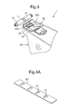
- FIG. 3 is a perspective view schematically illustrating a deployment shape of a passenger airbag cushion equipped with a tether holder according to the present invention
- FIGS. 4A to 4D are views schematically illustrating a tether of the passenger airbag cushion equipped with the tether holder according to the present invention.
- the passenger airbag module 1 is installed at an upper inner portion of a front surface of an instrument panel provided opposite to a passenger seat.
- the passenger airbag module 1 includes an inflator 10 that generates (N 2 ), an airbag cushion 20 deployed and inflated by the N 2 , and a tether 30 properly maintaining the deployment shape and length of the airbag cushion 20.
- the inflator 10 is designed such that the detonator thereof is ignited according to an impact signal for impact energy detected by the impact sensor.
- the inflator 10 has a gas generating agent used to generate the N 2 , and injects into the airbag cushion 20 through gas exhaust ports 11 formed at the center portion of the inflator 10.
- the airbag cushion 20 includes a front part 35b having a size sufficient to make contact with the head and the breast of the passenger such that the head and the breast of the passenger can be protected from impact in vehicle crash.
- the airbag cushion 20 includes a rear part 35a provided with a gas injection port 21 receiving the N 2 that has been exhausted from the gas exhaust ports 11 of the inflator 10.
- the airbag cushion 20 includes the tether 30, which connects the front part 35b of the airbag cushion 20 making contact with the body of the passenger with the rear part 35a of the airbag cushion 20 receiving the N 2 from the inflator 10 inside the airbag cushion 20, such that the deployment length and shape of the airbag cushion 20 can be properly maintained.
- the tether 30 includes an end fixed to the rear part 35a of the airbag cushion 20 through sewing, and an opposite end fixed to the front part 35b of the airbag cushion 20 through sewing.
- the tether 20 wounded around the inflator 10 and installed in the airbag cushion 20 can be freely bent, and can serve as a partition plate including a material the same as or different from that of the airbag cushion 20.
- the tether 30 is fixed by a tether holder 40 provided at an inner surface of the airbag cushion 20 before the tether 30 is deployed by the gas.
- the tether holder 40 has a rail shape and is fixed to the inner surface of the airbag cushion 20 to allow the tether 30 to be sequentially deployed.
- the tether 30 has a predetermined length and is folded in the tether holder 40 in the direction opposite to the deployment direction of the airbag cushion 20.
- the tether 30 is formed with frictional resistance reduction parts 31 to reduce a frictional area.
- FIG. 4A shows the frictional resistance reduction parts and FIGS. 4B to 4D show a frictional resistance increase part.
- the frictional resistance reduction parts 31 are formed by partially removing a surface area of the tether 30 to reduce the total area of the tether 30 without changing the external appearance of the tether 30.
- the frictional resistance increase part 33 is formed on a part of the tether 30, at which the tether 30 makes contact with the inner surface of the airbag cushion 20, to increase friction when the tether 30 is deployed so that the tether 30 is deployed after the frictional resistance reduction parts 31 are deployed.
- the frictional resistance increase part 33 increases the thickness of the tether 30.
- the frictional resistance increase part 33 has a predetermined length and is installed along the longitudinal center of the tether 30 in the deployment direction of the tether 30.
- the frictional resistance increase part 33 may include material identical to that of the tether 30.
- the frictional resistance increase part 33 may include various materials capable of enhancing frictional force with the airbag cushion 20.
- the frictional resistance reduction parts 31 and the frictional resistance increase part 33 are formed at the tether 30 such that the frictional resistance reduction parts 31 and the frictional resistance increase part 33 do not overlap each other.
- the total length of the frictional resistance reduction parts 31 formed in the tether 30 and the length of the frictional resistance increase part 33 formed on the tether 30 are identical to the length of the tether holder 40.
- the length of the tether 30 including the frictional resistance reduction parts 31 is substantially identical to the length of the rail-type tether holder 40, and the length of the frictional resistance increase part 33 is substantially identical to the length of the rail-type tether holder 40, so the frictional resistance reduction parts 31 are folded while facing the frictional resistance increase part 33, and are inserted into the tether holder 40.
- the frictional resistance increase part 33 may be fixed to the tether 30 through sewing or bonded to the tether 30 using an adhesive. As shown in FIG. 4D , the frictional resistance increase part 33 may be formed by coating the longitudinal center of the tether 30 with coating material C such that frictional force of the longitudinal center of the tether 30 is increased. After the frictional resistance increase part 33 and the frictional resistance reduction parts 31 of the tether 30 are folded and restrained by the tether holder 40, a fixing part 50 is provided to fix the tether holder 40 together with the frictional resistance increase part 33 and the frictional resistance reduction parts 31.
- the fixing part 50 is destroyed when the fixing part 50 is subject to predetermined pressure.
- the fixing part 50 may be coupled with the tether holder 40 through sewing, or bonding.
- Various structures can be used for the fixing part 50 when the fixing part 50 can be destroyed by pressure of gas generated from the inflator 10.
- FIGS. 5A and 5B are perspective views schematically showing the tether holder and the tether according to a deployment process of the passenger airbag cushion equipped with the tether holder according to the present invention.
- the gas is exhausted from the inflator 10 to form predetermined gas pressure, so the tether holder 40 is destroyed.
- the tether 30 is withdrawn from the tether holder 40 to restrain the deployment length of the airbag cushion 20.
- the frictional resistance reduction parts 31 of the tether 30 which have been folded in the tether holder 40, is withdrawn prior to the frictional resistance increase part 33 with the deployment of the end of the tether 30.
- the frictional resistance increase part 33 is withdrawn toward the front part 35b.
- the tether holder 40 supports the tether 30 such that the tether 30 is sequentially deployed and simultaneously fixes the tether 30 to the inner surface of the airbag cushion 20.
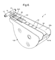
- FIG. 6 is a perspective views schematically showing the deployment shape of the passenger airbag cushion equipped with the tether holder according to the present invention.
- the tether 30 is released from the tether holder 40 in such a manner that the frictional resistance reduction parts 31 having relatively low friction are primarily withdrawn while being induced by a part connected to the front part 35b, and the frictional resistance increase part 33 connected with the frictional resistance reduction parts 31 is secondarily withdrawn.
- the airbag cushion 20 is deployed corresponding to the length of the tether 30 while being fixed to both ends of the tether 30.
- FIG. 7 is a perspective view showing a folded shape of the airbag cushion and the tether according to an embodiment of the present invention. Referring to FIG. 7 , the tether 30 that properly maintains the deployment length of the airbag cushion 20 is fixed to the inflator 10 while surrounding the inflator 10.
- the tether 30 surrounds the outer surface of the inflator 10 installed at the outer surface of one side of an airbag housing, and both ends of the tether 30 are fixed to the inner part of the airbag cushion 20 through sewing or bonding.
- the airbag cushion 20 is folded and accommodated in the airbag housing provided in the instrument panel of a passenger seat of a vehicle.
- the airbag cushion 20 includes a first part that is folded in parallel to an upper part of the inflator 10 and a second part that is folded in parallel to a side part of the inflator 10.
- FIGS. 8A to 8F are views showing the deployment process of the airbag cushion according to the embodiment of the present invention. Referring to FIGS. 8A to 8F , when a predetermined impact is applied to the vehicle, the airbag system operates.
- the airbag cushion 20 is inflated toward the passenger.
- the tether 30 properly maintains the deployment length of the airbag cushion 20, and the airbag cushion 20 is deployed toward the passenger corresponding to the length of the tether 30, so that the impact applied to the passenger can be attenuated.
- FIG. 8A shows an initial inflation process of the airbag cushion 20
- the airbag cushion 20 is deployed upward to make contact with a windshield.
- FIG. 8B the airbag cushion 20 is inflated toward the passenger and is simultaneously deployed toward the lower part of the body of the passenger along the outer surface of the instrument panel.
- the speed of the airbag cushion 20 deployed toward the passenger can be decreased according to the folded shape of the tether 30. As shown FIG. 8C , since the tether 30 is folded in a location adjacent to the windshield, the deployment speed of the airbag cushion 20 can be reduced corresponding to the release speed of the tether 30.
- the speed of the airbag cushion 20 deployed toward the passenger is reduced, so that the passenger can be prevented from being injured due to the airbag cushion 20.
- load applied to the windshield is distributed, so that the windshield can be prevented from being damaged.
Abstract
Description
- The present invention relates to a tether, which interconnects a front part and a rear part of a passenger airbag cushion for a vehicle, and a tether holder supporting the tether. More particularly, the present invention relates to a passenger airbag cushion equipped with a tether holder which is folded in a direction opposite to a deployment direction of the tether to fix the tether such that the tether is prevented from being twisted and folded when the tether is deployed by gas generated from an inflator.
- Generally, a vehicle is provided therein with seat belts, which restrain passengers as well as a driver for the sake of safety in crash, in order to attenuate deceleration exerted on a body of the passenger. The seat belt prevents the passengers from spring out of the vehicle upon a collision while preventing passengers from being subject to the second collision and attenuating impact applied to the passengers.
- In addition to the seat belt, the vehicle is provided with an airbag module instantly expanding an airbag between a driver and a steering wheel or between a passenger in a passenger seat and an instrument panel in crash to attenuate the injury of the driver or the passenger caused by impact occurring in the crash.
-
FIG.1 is a sectional view schematically showing an airbag module according to the related art, andFIG. 2 is a perspective view schematically showing a deployment shape of a passenger airbag module for a vehicle according to the related art. - As shown in
FIGS. 1 and2 , apassenger airbag module 100 for a vehicle includes aninflator 110, anairbag cushion 120, and atether 130. Theinflator 110 generates nitrogen gas (N2) upon explosion of a detonator. Theairbag cushion 120 expands or deploys through a deployment part by nitrogen gas generated from theinflator 110. Thetether 130 connects a front part of theairbag cushion 120, which makes contact with the body of the passenger, with a rear part of theairbag cushion 120, into which nitrogen gas is injected from theinflator 110.
Theinflator 110 of theairbag module 100 includes a gas generating agent generating the N2 as the detonator of theinflator 110 is ignited, and thetether 130 is deployed by the nitrogen gas in a state in which thetether 130 is wound around theinflator 110. - In order to constantly maintain the deployment length of the
airbag cushion 120, theairbag module 100 includes afirst support part 131 a fixing one end of thetether 130 to the rear part of theairbag cushion 120 and asecond support part 131 b fixing the other end of thetether 130 to the front part of theairbag cushion 120. - Regarding the operation of the
airbag module 100 having the above structure, when the driving speed of the vehicle is abruptly decreased due to head-on crash, the impact sensor detects the impact occurring in the head-on crash and generates the impact signal. - At this time, the electronic control module recognizes the impact signal, so the electronic control module ignites the detonator of the
inflator 110 to burn a gas generating agent of theinflator 110, so that the gas generating agent generates the N2. While moving fromgas exhaust ports 111 formed in theinflator 110 to agas injection port 121 of theairbag cushion 120, the nitrogen gas expands or deploys theairbag cushion 120 toward the passenger. - The deployed
airbag cushion 120 makes contact with the passenger to partially absorb impact. In addition, when the deployedairbag cushion 120 collides with the head or the breast of the passenger by inertia, the N2 of theairbag cushion 120 is rapidly exhausted through gas exhaust holes of theairbag cushion 120 to attenuate the impact exerted on the front part of the passenger. - Accordingly, impact power applied to the passenger in the crash of the vehicle is effectively attenuated, so that the second collision, that is, the collision between other components of the vehicle and the body of the passenger can be reduced.
- However, when the
tether 130 wound around the inflator is deployed by the N2, thetether 130 cannot be linearly deployed toward the passenger, but can be spirally deployed due to the increase of the friction between the inflator and the tether. In addition, when thetether 130 is spirally deployed, thetether 130 may be twisted so that the deployment length of the airbag cushion is reduced, and the impact absorbing effect is reduced at the front of the passenger due to the reduction in deployment length of the airbag cushion. Accordingly, the airbag cushion may be abnormally deployed. - The present invention has been made to solve the above problem occurring in the prior art, and an object of the present invention is to provide a passenger airbag cushion of a vehicle, in which a tether includes a tether holder for fixing a tether such that the tether can be prevented from being twisted due to friction between the tether and an inflator when the tether is deployed, to allow the tether to be fixed and sequentially deployed.
- Another object of the present invention is to provide a passenger airbag cushion of a vehicle, capable of increasing frictional resistance on a surface of a tether, which makes contact with the tether holder, and reducing frictional resistance on a surface of the tether, which does not make contact with the tether holder, thereby allowing the tether, which is folded and restrained in the tether holder, to be sequentially deployed.
- Another object of the present invention is to provide a passenger airbag cushion of a vehicle, in which the twist prevention structure includes a fixing part that fixes the tether to a tether holder unless pressure exceeds a predetermined level.
- According to the present invention as described above, the tether can be prevented from being folded while being shaken during deployment and inflation of the airbag cushion, and the airbag cushion can be exactly deployed and inflated by preventing deployment length of the tether from being reduced due to twist and folding. Further, the airbag cushion is exactly deployed and inflated toward a passenger, so that an impact applied to the passenger can be attenuated.
- In order to accomplish the above object, according to one aspect of the present invention, there is provided a passenger airbag cushion including a tether wound around an inflator installed in a dashboard of a passenger seat of a vehicle while being connected with both ends of an inner surface of an airbag cushion, and restraining the airbag cushion deployed and inflated by gas generated from the inflator, and a tether holder allowing the tether to be folded in a direction opposite to a deployment direction of the tether, which is deployed by the inflator, and restraining the tether such that the tether is fixed to the tether holder.
- The above and other objects, features and other advantages of the present invention will be more clearly understood from the following detailed description when taken in conjunction with the accompanying drawings, in which:
-
FIG.1 is a perspective view schematically showing a passenger airbag module for a vehicle according to the related art; -
FIG. 2 is a perspective view schematically showing a deployment shape of a passenger airbag cushion for a vehicle according to the related art; -
FIG. 3 is a perspective view schematically illustrating a deployment shape of a passenger airbag cushion equipped with a tether holder used in a vehicle according to the present invention; -
FIGS. 4A to 4D are views schematically illustrating various tethers of a passenger airbag cushion equipped with a tether holder used in a vehicle according to the present invention; -
FIG. 5A is a perspective view showing a tether which is not deployed from a tether holder in a passenger airbag cushion equipped with a tether holder used in a vehicle according to the present invention;
FIG. 5B is a perspective view showing a tether which is partially deployed from a tether holder in a passenger airbag cushion equipped with a tether holder used in a vehicle according to the present invention; -
FIG. 6 is a perspective views schematically showing a deployment shape of a passenger airbag cushion equipped with a tether holder according to the present invention; -
FIG. 7 is a perspective view showing a folded shape of an airbag cushion and a tether according to an embodiment of the present invention; and -
FIGS. 8A to 8F are views showing a deployment process of an airbag cushion according to an embodiment of the present invention. - Hereinafter, an embodiment according to the present invention will be described in detail with reference to the accompanying drawings.
-
FIG. 3 is a perspective view schematically illustrating a deployment shape of a passenger airbag cushion equipped with a tether holder according to the present invention, andFIGS. 4A to 4D are views schematically illustrating a tether of the passenger airbag cushion equipped with the tether holder according to the present invention. - Referring to
FIG. 3 , thepassenger airbag module 1 according to the present invention is installed at an upper inner portion of a front surface of an instrument panel provided opposite to a passenger seat. - In this regard, the
passenger airbag module 1 includes aninflator 10 that generates (N2), anairbag cushion 20 deployed and inflated by the N2, and atether 30 properly maintaining the deployment shape and length of theairbag cushion 20. - The
inflator 10 is designed such that the detonator thereof is ignited according to an impact signal for impact energy detected by the impact sensor. In addition, theinflator 10 has a gas generating agent used to generate the N2, and injects into theairbag cushion 20 throughgas exhaust ports 11 formed at the center portion of theinflator 10. - The
airbag cushion 20 includes afront part 35b having a size sufficient to make contact with the head and the breast of the passenger such that the head and the breast of the passenger can be protected from impact in vehicle crash. Theairbag cushion 20 includes arear part 35a provided with agas injection port 21 receiving the N2 that has been exhausted from thegas exhaust ports 11 of theinflator 10. - The
airbag cushion 20 includes thetether 30, which connects thefront part 35b of theairbag cushion 20 making contact with the body of the passenger with therear part 35a of theairbag cushion 20 receiving the N2 from theinflator 10 inside theairbag cushion 20, such that the deployment length and shape of theairbag cushion 20 can be properly maintained. - Further, the
tether 30 includes an end fixed to therear part 35a of theairbag cushion 20 through sewing, and an opposite end fixed to thefront part 35b of theairbag cushion 20 through sewing. - The
tether 20 wounded around theinflator 10 and installed in theairbag cushion 20 can be freely bent, and can serve as a partition plate including a material the same as or different from that of theairbag cushion 20. - Furthermore, the
tether 30 is fixed by atether holder 40 provided at an inner surface of theairbag cushion 20 before thetether 30 is deployed by the gas. - The
tether holder 40 has a rail shape and is fixed to the inner surface of theairbag cushion 20 to allow thetether 30 to be sequentially deployed. - The
tether 30 has a predetermined length and is folded in thetether holder 40 in the direction opposite to the deployment direction of theairbag cushion 20. Thetether 30 is formed with frictionalresistance reduction parts 31 to reduce a frictional area. -
FIG. 4A shows the frictional resistance reduction parts andFIGS. 4B to 4D show a frictional resistance increase part. The frictionalresistance reduction parts 31 are formed by partially removing a surface area of thetether 30 to reduce the total area of thetether 30 without changing the external appearance of thetether 30. - The frictional resistance increase
part 33 is formed on a part of thetether 30, at which thetether 30 makes contact with the inner surface of theairbag cushion 20, to increase friction when thetether 30 is deployed so that thetether 30 is deployed after the frictionalresistance reduction parts 31 are deployed. - The frictional resistance increase
part 33 increases the thickness of thetether 30. In detail, the frictional resistance increasepart 33 has a predetermined length and is installed along the longitudinal center of thetether 30 in the deployment direction of thetether 30. - The frictional resistance increase
part 33 may include material identical to that of thetether 30. The frictional resistance increasepart 33 may include various materials capable of enhancing frictional force with theairbag cushion 20. - In addition, the frictional
resistance reduction parts 31 and the frictional resistance increasepart 33 are formed at thetether 30 such that the frictionalresistance reduction parts 31 and the frictional resistance increasepart 33 do not overlap each other. Preferably, the total length of the frictionalresistance reduction parts 31 formed in thetether 30 and the length of the frictional resistance increasepart 33 formed on thetether 30 are identical to the length of thetether holder 40. - In detail, the length of the
tether 30 including the frictionalresistance reduction parts 31 is substantially identical to the length of the rail-type tether holder 40, and the length of the frictional resistance increasepart 33 is substantially identical to the length of the rail-type tether holder 40, so the frictionalresistance reduction parts 31 are folded while facing the frictional resistance increasepart 33, and are inserted into thetether holder 40. - Referring to
FIGS. 4B and 4C , the frictional resistance increasepart 33 may be fixed to thetether 30 through sewing or bonded to thetether 30 using an adhesive. As shown inFIG. 4D , the frictional resistance increasepart 33 may be formed by coating the longitudinal center of thetether 30 with coating material C such that frictional force of the longitudinal center of thetether 30 is increased. After the frictional resistance increasepart 33 and the frictionalresistance reduction parts 31 of thetether 30 are folded and restrained by thetether holder 40, a fixingpart 50 is provided to fix thetether holder 40 together with the frictional resistance increasepart 33 and the frictionalresistance reduction parts 31. - The fixing
part 50 is destroyed when the fixingpart 50 is subject to predetermined pressure. Preferably, the fixingpart 50 may be coupled with thetether holder 40 through sewing, or bonding. Various structures can be used for the fixingpart 50 when the fixingpart 50 can be destroyed by pressure of gas generated from theinflator 10. -
FIGS. 5A and 5B are perspective views schematically showing the tether holder and the tether according to a deployment process of the passenger airbag cushion equipped with the tether holder according to the present invention. Referring toFIG. 5A , the gas is exhausted from the inflator 10 to form predetermined gas pressure, so thetether holder 40 is destroyed. - Referring to
FIG. 5B , when the fixingpart 50 is destroyed and theairbag cushion 20 is deployed toward thefront part 35b, thetether 30 is withdrawn from thetether holder 40 to restrain the deployment length of theairbag cushion 20. At this time, since the opposite end of thetether 30 is connected with thefront part 35b, when thefront part 35b is deployed toward a front part of the passenger, the frictionalresistance reduction parts 31 of thetether 30, which have been folded in thetether holder 40, is withdrawn prior to the frictional resistance increasepart 33 with the deployment of the end of thetether 30. After the frictionalresistance reduction parts 31 is withdrawn toward therear part 35a, since thetether 30 having the frictionalresistance reduction parts 31 pulls the frictional resistance increasepart 33, the frictional resistance increasepart 33 is withdrawn toward thefront part 35b. - At this time, the
tether holder 40 supports thetether 30 such that thetether 30 is sequentially deployed and simultaneously fixes thetether 30 to the inner surface of theairbag cushion 20. -
FIG. 6 is a perspective views schematically showing the deployment shape of the passenger airbag cushion equipped with the tether holder according to the present invention. Referring toFIG. 6 , thetether 30 is released from thetether holder 40 in such a manner that the frictionalresistance reduction parts 31 having relatively low friction are primarily withdrawn while being induced by a part connected to thefront part 35b, and the frictional resistance increasepart 33 connected with the frictionalresistance reduction parts 31 is secondarily withdrawn. In such a case, since the end of thetether 30 is connected with therear part 35a, theairbag cushion 20 is deployed corresponding to the length of thetether 30 while being fixed to both ends of thetether 30. -
FIG. 7 is a perspective view showing a folded shape of the airbag cushion and the tether according to an embodiment of the present invention. Referring toFIG. 7 , thetether 30 that properly maintains the deployment length of theairbag cushion 20 is fixed to the inflator 10 while surrounding theinflator 10. - The
tether 30 surrounds the outer surface of the inflator 10 installed at the outer surface of one side of an airbag housing, and both ends of thetether 30 are fixed to the inner part of theairbag cushion 20 through sewing or bonding. Theairbag cushion 20 is folded and accommodated in the airbag housing provided in the instrument panel of a passenger seat of a vehicle. In detail, theairbag cushion 20 includes a first part that is folded in parallel to an upper part of the inflator 10 and a second part that is folded in parallel to a side part of theinflator 10. -
FIGS. 8A to 8F are views showing the deployment process of the airbag cushion according to the embodiment of the present invention. Referring toFIGS. 8A to 8F , when a predetermined impact is applied to the vehicle, the airbag system operates. - First, as the gas exhausted from the inflator 10 is injected into the
airbag cushion 20, theairbag cushion 20 is inflated toward the passenger. At this time, thetether 30 properly maintains the deployment length of theairbag cushion 20, and theairbag cushion 20 is deployed toward the passenger corresponding to the length of thetether 30, so that the impact applied to the passenger can be attenuated. - Referring to
FIG. 8A that shows an initial inflation process of theairbag cushion 20, theairbag cushion 20 is deployed upward to make contact with a windshield. As shownFIG. 8B , theairbag cushion 20 is inflated toward the passenger and is simultaneously deployed toward the lower part of the body of the passenger along the outer surface of the instrument panel. - The speed of the
airbag cushion 20 deployed toward the passenger can be decreased according to the folded shape of thetether 30. As shownFIG. 8C , since thetether 30 is folded in a location adjacent to the windshield, the deployment speed of theairbag cushion 20 can be reduced corresponding to the release speed of thetether 30. - Thus, the speed of the
airbag cushion 20 deployed toward the passenger is reduced, so that the passenger can be prevented from being injured due to theairbag cushion 20. Simultaneously, load applied to the windshield is distributed, so that the windshield can be prevented from being damaged. - Although few embodiments of the present invention have been shown and described, it would be appreciated by those skilled in the art that changes may be made in these embodiments without departing from the principles and sprit of the invention, the scope of which is defined in the claims and their equivalents.
Claims (11)
- A passenger airbag cushion comprising:a tether wound around an inflator installed in a dashboard of a passenger seat of a vehicle while being connected with both ends of an inner surface of an airbag cushion, and restraining the airbag cushion deployed and inflated by gas generated from the inflator; andtether holder allowing the tether to be folded in a direction opposite to a deployment direction of the tether, which is deployed by the inflator, and restraining the tether such that the tether is fixed to the tether holder.
- The passenger airbag cushion as claimed in claim 1, further comprising a fixing part that fixes the tether to the tether holder until predetermined pressure is applied to the tether restrained in the tether holder.
- The passenger airbag cushion as claimed in claim 2, wherein the fixing part fixes the tether to the tether holder such that the tether is restrained in the tether holder, and the tether is released from the tether holder by pressure of gas exhausted from the inflator.
- The passenger airbag cushion as claimed in claim 3, wherein the fixing part is fixed to the tether holder through sewing or bonding.
- The passenger airbag cushion as claimed in claim 1, wherein the tether is partially folded in a direction opposite to a deployment direction of the airbag cushion.
- The passenger airbag cushion as claimed in claim 5, further comprising frictional resistance reduction parts which are formed at a folded part of the tether, which makes contact with the tether holder, to reduce frictional resistance with the tether holder.
- The passenger airbag cushion as claimed in claim 6, wherein the frictional resistance reduction parts are formed by partially removing a surface area of the tether.
- The passenger airbag cushion as claimed in claim 7, further comprising a frictional resistance increase part which is formed at the folded part of the tether, which makes contact with the airbag cushion, to increase friction with the airbag cushion by increasing thickness of the tether.
- The passenger airbag cushion as claimed in claim 8, wherein the frictional resistance increase part is coated with coating material having predetermined thickness such that the thickness of the tether is increased.
- The passenger airbag cushion as claimed in claim 9, wherein the frictional resistance increase part is the same material as material constituting the tether such that the thickness of the tether is increased due to the material.
- The passenger airbag cushion as claimed in claim 10, wherein the frictional resistance increase part is fixed to the tether through sewing or bonding.
Applications Claiming Priority (1)
| Application Number | Priority Date | Filing Date | Title |
|---|---|---|---|
| KR1020080043429A KR100990035B1 (en) | 2008-05-09 | 2008-05-09 | A twist prevention structure for the passenger airbag cushion having tether holder of automobile |
Publications (2)
| Publication Number | Publication Date |
|---|---|
| EP2116430A1 true EP2116430A1 (en) | 2009-11-11 |
| EP2116430B1 EP2116430B1 (en) | 2013-03-20 |
Family
ID=40940163
Family Applications (1)
| Application Number | Title | Priority Date | Filing Date |
|---|---|---|---|
| EP09159494A Not-in-force EP2116430B1 (en) | 2008-05-09 | 2009-05-06 | Passenger airbag cushion having tether holder used in a vehicle |
Country Status (4)
| Country | Link |
|---|---|
| US (1) | US7980593B2 (en) |
| EP (1) | EP2116430B1 (en) |
| KR (1) | KR100990035B1 (en) |
| CN (1) | CN201566582U (en) |
Families Citing this family (10)
| Publication number | Priority date | Publication date | Assignee | Title |
|---|---|---|---|---|
| US8696022B2 (en) | 2010-10-27 | 2014-04-15 | Trw Vehicle Safety Systems Inc. | Air bag with variable venting |
| US8684404B2 (en) | 2010-10-27 | 2014-04-01 | Trw Vehicle Safety Systems Inc. | Air bag with variable venting |
| DE102013108004B4 (en) * | 2013-07-26 | 2017-08-10 | Autoliv Development Ab | Airbag module with a gas bag having a vent opening closed in the folded state by a tether and method for the production thereof |
| EP2910435B1 (en) * | 2014-02-20 | 2017-04-12 | Dalphi Metal España, S.A. | Airbag |
| US9815429B2 (en) | 2016-02-23 | 2017-11-14 | Autoliv Asp, Inc. | Adaptive vent for knee airbag |
| US10471927B1 (en) * | 2017-09-13 | 2019-11-12 | Waymo Llc | Tethered airbags |
| JP6973342B2 (en) * | 2018-09-25 | 2021-11-24 | 豊田合成株式会社 | Airbag |
| US10946828B2 (en) | 2019-01-04 | 2021-03-16 | Ford Global Technologies, Llc | Multi-layered tether |
| DE102019208352A1 (en) * | 2019-06-07 | 2020-12-10 | Psa Automobiles Sa | Apparatus and method for setting an extension of an airbag with a retaining strap that is adjustable in length and retains the airbag |
| JP7217811B2 (en) * | 2019-08-07 | 2023-02-03 | オートリブ ディベロップメント エービー | passenger restraint system |
Citations (4)
| Publication number | Priority date | Publication date | Assignee | Title |
|---|---|---|---|---|
| DE29521695U1 (en) * | 1995-02-17 | 1998-03-05 | Petri Ag | Airbag module |
| US6113134A (en) * | 1998-08-31 | 2000-09-05 | Hyundai Motor Company | Airbag system of automotive vehicle |
| US20060061076A1 (en) | 2002-02-20 | 2006-03-23 | Webber James L | Apparatus and method for controlling an inflatable cushion |
| WO2007046740A1 (en) * | 2005-10-18 | 2007-04-26 | Autoliv Development Ab | A safety arrangement |
Family Cites Families (22)
| Publication number | Priority date | Publication date | Assignee | Title |
|---|---|---|---|---|
| JP3168591B2 (en) * | 1991-03-12 | 2001-05-21 | トヨタ自動車株式会社 | Airbag device |
| US5280953A (en) * | 1992-11-25 | 1994-01-25 | General Motors Corporation | Displacement responsive air bag vent |
| US5570905A (en) * | 1995-03-28 | 1996-11-05 | Morton International, Inc. | Airbag tether attachment |
| US6254130B1 (en) * | 1998-04-13 | 2001-07-03 | Georgia Tech Research Corporation | Method and apparatus for controlling air bag deployment |
| US6422597B1 (en) | 1999-11-12 | 2002-07-23 | Delphi Technologies, Inc. | Variable profile air bag restraint |
| US6361072B1 (en) * | 2000-05-11 | 2002-03-26 | Bertron O. Barnes | Air bag contoured for safety |
| US6715791B2 (en) * | 2001-04-06 | 2004-04-06 | Milliken & Company | Air bag tether system comprising multiple segments cut in alignment with fabric warp of fill |
| US6616184B2 (en) * | 2001-04-25 | 2003-09-09 | Trw Vehicle Safety Systems Inc. | Vehicle occupant protection apparatus with inflation volume and shape control |
| US6955377B2 (en) | 2002-04-06 | 2005-10-18 | Key Safety Systems, Inc. | Inflatable restraint module with external tether |
| US6869103B2 (en) * | 2002-12-13 | 2005-03-22 | Delphi Technologies, Inc. | Apparatus and method for controlling an inflatable cushion |
| US6871874B2 (en) * | 2002-12-18 | 2005-03-29 | Key Safety Systems, Inc. | Airbag deployment velocity sensor |
| US6857659B2 (en) * | 2002-12-20 | 2005-02-22 | Delphi Technologies, Inc. | Air bag module including restrained inflatable cushion |
| US7111871B2 (en) * | 2003-08-02 | 2006-09-26 | General Motors Corporation | Automotive vehicle air bag system |
| US7722080B2 (en) * | 2006-09-27 | 2010-05-25 | Autoliv Asp, Inc. | Airbag cushion with a flap vent to optionally vent gas for out-of-position conditions |
| US7261319B2 (en) * | 2005-01-07 | 2007-08-28 | Autoliv Asp, Inc. | Airbag cushion with adaptive venting for reduced out-of-position effects |
| US7354064B2 (en) * | 2005-02-01 | 2008-04-08 | Key Safety Systems, Inc. | Active tether air bag module |
| US7568727B2 (en) * | 2005-04-06 | 2009-08-04 | Ford Global Technologies, Llc | Airbag deployment monitoring system |
| JP4683388B2 (en) * | 2005-09-07 | 2011-05-18 | タカタ株式会社 | Airbag device, motorcycle with airbag device |
| JP5474275B2 (en) * | 2005-09-21 | 2014-04-16 | ティーケー ホールディングス,インコーポレーテッド | Passive airbag degassing |
| DE102006005793A1 (en) * | 2006-02-08 | 2007-08-16 | Trw Automotive Gmbh | airbag |
| DE102006031542A1 (en) * | 2006-07-07 | 2008-01-10 | Trw Automotive Gmbh | Airbag for a vehicle occupant restraint system |
| JP2008284930A (en) * | 2007-05-15 | 2008-11-27 | Toyoda Gosei Co Ltd | Airbag device |
-
2008
- 2008-05-09 KR KR1020080043429A patent/KR100990035B1/en not_active IP Right Cessation
-
2009
- 2009-05-06 EP EP09159494A patent/EP2116430B1/en not_active Not-in-force
- 2009-05-08 CN CN2009201530315U patent/CN201566582U/en not_active Expired - Fee Related
- 2009-05-08 US US12/437,570 patent/US7980593B2/en not_active Expired - Fee Related
Patent Citations (4)
| Publication number | Priority date | Publication date | Assignee | Title |
|---|---|---|---|---|
| DE29521695U1 (en) * | 1995-02-17 | 1998-03-05 | Petri Ag | Airbag module |
| US6113134A (en) * | 1998-08-31 | 2000-09-05 | Hyundai Motor Company | Airbag system of automotive vehicle |
| US20060061076A1 (en) | 2002-02-20 | 2006-03-23 | Webber James L | Apparatus and method for controlling an inflatable cushion |
| WO2007046740A1 (en) * | 2005-10-18 | 2007-04-26 | Autoliv Development Ab | A safety arrangement |
Also Published As
| Publication number | Publication date |
|---|---|
| CN201566582U (en) | 2010-09-01 |
| US20090278341A1 (en) | 2009-11-12 |
| US7980593B2 (en) | 2011-07-19 |
| KR100990035B1 (en) | 2010-10-26 |
| KR20090117400A (en) | 2009-11-12 |
| EP2116430B1 (en) | 2013-03-20 |
Similar Documents
| Publication | Publication Date | Title |
|---|---|---|
| EP2116430B1 (en) | Passenger airbag cushion having tether holder used in a vehicle | |
| US7963550B2 (en) | Knee airbag and method of folding the same | |
| KR100636641B1 (en) | Passenger air-bag module | |
| JP6294952B2 (en) | Double-folded cushion for IC | |
| JP2007216954A (en) | Sleeve and tether to form cushion for air bag | |
| JP5572348B2 (en) | Roof airbag device for vehicle | |
| EP2119604B1 (en) | Tether for airbag cushion of vehicle | |
| JP4576308B2 (en) | Automotive airbag equipment | |
| KR100947997B1 (en) | Folding Method For Air Bag | |
| JP2022145179A (en) | Air bag device for vehicle | |
| KR101010826B1 (en) | Bracket for mounting a curtain air bag | |
| JP7439460B2 (en) | air bag device | |
| KR100622428B1 (en) | Passenger air-bag module | |
| KR100788189B1 (en) | Passenger air bag module for car and folding method of the same | |
| KR100707889B1 (en) | Cushion assembly of air bag of vehicle | |
| KR100947995B1 (en) | Air Bag For Vehicle | |
| KR100938532B1 (en) | Air Bag Housing | |
| KR101326941B1 (en) | Passenger Air-Bag for Vehicle | |
| KR100512854B1 (en) | Passenger air bag for car | |
| KR20030026468A (en) | Tether and vent-hole connection type airbag-cusion for automobile | |
| KR100622119B1 (en) | Passenger air bag module for car | |
| KR100750403B1 (en) | Side air bag for automobile | |
| KR100835942B1 (en) | Tether for air bag | |
| KR100989491B1 (en) | Passenger air bag and unfolding method thereof | |
| KR19990009324U (en) | Tether coupling structure of airbag cushion |
Legal Events
| Date | Code | Title | Description |
|---|---|---|---|
| PUAI | Public reference made under article 153(3) epc to a published international application that has entered the european phase |
Free format text: ORIGINAL CODE: 0009012 |
|
| AK | Designated contracting states |
Kind code of ref document: A1 Designated state(s): AT BE BG CH CY CZ DE DK EE ES FI FR GB GR HR HU IE IS IT LI LT LU LV MC MK MT NL NO PL PT RO SE SI SK TR |
|
| 17P | Request for examination filed |
Effective date: 20100504 |
|
| 17Q | First examination report despatched |
Effective date: 20100608 |
|
| RAP1 | Party data changed (applicant data changed or rights of an application transferred) |
Owner name: DELPHI KOREA LIMITED LIABILITY COMPANY |
|
| RAP1 | Party data changed (applicant data changed or rights of an application transferred) |
Owner name: AUTOLIV DEVELOPMENT AB |
|
| REG | Reference to a national code |
Ref country code: DE Ref legal event code: R079 Ref document number: 602009014078 Country of ref document: DE Free format text: PREVIOUS MAIN CLASS: B60R0021233000 Ipc: B60R0021233800 |
|
| RIC1 | Information provided on ipc code assigned before grant |
Ipc: B60R 21/2338 20110101AFI20120724BHEP |
|
| GRAP | Despatch of communication of intention to grant a patent |
Free format text: ORIGINAL CODE: EPIDOSNIGR1 |
|
| GRAS | Grant fee paid |
Free format text: ORIGINAL CODE: EPIDOSNIGR3 |
|
| GRAA | (expected) grant |
Free format text: ORIGINAL CODE: 0009210 |
|
| AK | Designated contracting states |
Kind code of ref document: B1 Designated state(s): AT BE BG CH CY CZ DE DK EE ES FI FR GB GR HR HU IE IS IT LI LT LU LV MC MK MT NL NO PL PT RO SE SI SK TR |
|
| REG | Reference to a national code |
Ref country code: GB Ref legal event code: FG4D |
|
| REG | Reference to a national code |
Ref country code: CH Ref legal event code: EP |
|
| REG | Reference to a national code |
Ref country code: IE Ref legal event code: FG4D |
|
| REG | Reference to a national code |
Ref country code: AT Ref legal event code: REF Ref document number: 601870 Country of ref document: AT Kind code of ref document: T Effective date: 20130415 |
|
| REG | Reference to a national code |
Ref country code: DE Ref legal event code: R096 Ref document number: 602009014078 Country of ref document: DE Effective date: 20130516 |
|
| PG25 | Lapsed in a contracting state [announced via postgrant information from national office to epo] |
Ref country code: ES Free format text: LAPSE BECAUSE OF FAILURE TO SUBMIT A TRANSLATION OF THE DESCRIPTION OR TO PAY THE FEE WITHIN THE PRESCRIBED TIME-LIMIT Effective date: 20130701 Ref country code: LT Free format text: LAPSE BECAUSE OF FAILURE TO SUBMIT A TRANSLATION OF THE DESCRIPTION OR TO PAY THE FEE WITHIN THE PRESCRIBED TIME-LIMIT Effective date: 20130320 Ref country code: SE Free format text: LAPSE BECAUSE OF FAILURE TO SUBMIT A TRANSLATION OF THE DESCRIPTION OR TO PAY THE FEE WITHIN THE PRESCRIBED TIME-LIMIT Effective date: 20130320 Ref country code: NO Free format text: LAPSE BECAUSE OF FAILURE TO SUBMIT A TRANSLATION OF THE DESCRIPTION OR TO PAY THE FEE WITHIN THE PRESCRIBED TIME-LIMIT Effective date: 20130620 Ref country code: BG Free format text: LAPSE BECAUSE OF FAILURE TO SUBMIT A TRANSLATION OF THE DESCRIPTION OR TO PAY THE FEE WITHIN THE PRESCRIBED TIME-LIMIT Effective date: 20130620 |
|
| REG | Reference to a national code |
Ref country code: AT Ref legal event code: MK05 Ref document number: 601870 Country of ref document: AT Kind code of ref document: T Effective date: 20130320 |
|
| REG | Reference to a national code |
Ref country code: LT Ref legal event code: MG4D |
|
| PG25 | Lapsed in a contracting state [announced via postgrant information from national office to epo] |
Ref country code: SI Free format text: LAPSE BECAUSE OF FAILURE TO SUBMIT A TRANSLATION OF THE DESCRIPTION OR TO PAY THE FEE WITHIN THE PRESCRIBED TIME-LIMIT Effective date: 20130320 Ref country code: FI Free format text: LAPSE BECAUSE OF FAILURE TO SUBMIT A TRANSLATION OF THE DESCRIPTION OR TO PAY THE FEE WITHIN THE PRESCRIBED TIME-LIMIT Effective date: 20130320 Ref country code: LV Free format text: LAPSE BECAUSE OF FAILURE TO SUBMIT A TRANSLATION OF THE DESCRIPTION OR TO PAY THE FEE WITHIN THE PRESCRIBED TIME-LIMIT Effective date: 20130320 Ref country code: GR Free format text: LAPSE BECAUSE OF FAILURE TO SUBMIT A TRANSLATION OF THE DESCRIPTION OR TO PAY THE FEE WITHIN THE PRESCRIBED TIME-LIMIT Effective date: 20130621 |
|
| REG | Reference to a national code |
Ref country code: NL Ref legal event code: VDEP Effective date: 20130320 |
|
| PG25 | Lapsed in a contracting state [announced via postgrant information from national office to epo] |
Ref country code: HR Free format text: LAPSE BECAUSE OF FAILURE TO SUBMIT A TRANSLATION OF THE DESCRIPTION OR TO PAY THE FEE WITHIN THE PRESCRIBED TIME-LIMIT Effective date: 20130320 Ref country code: BE Free format text: LAPSE BECAUSE OF FAILURE TO SUBMIT A TRANSLATION OF THE DESCRIPTION OR TO PAY THE FEE WITHIN THE PRESCRIBED TIME-LIMIT Effective date: 20130320 |
|
| PG25 | Lapsed in a contracting state [announced via postgrant information from national office to epo] |
Ref country code: SK Free format text: LAPSE BECAUSE OF FAILURE TO SUBMIT A TRANSLATION OF THE DESCRIPTION OR TO PAY THE FEE WITHIN THE PRESCRIBED TIME-LIMIT Effective date: 20130320 Ref country code: NL Free format text: LAPSE BECAUSE OF FAILURE TO SUBMIT A TRANSLATION OF THE DESCRIPTION OR TO PAY THE FEE WITHIN THE PRESCRIBED TIME-LIMIT Effective date: 20130320 Ref country code: RO Free format text: LAPSE BECAUSE OF FAILURE TO SUBMIT A TRANSLATION OF THE DESCRIPTION OR TO PAY THE FEE WITHIN THE PRESCRIBED TIME-LIMIT Effective date: 20130320 Ref country code: AT Free format text: LAPSE BECAUSE OF FAILURE TO SUBMIT A TRANSLATION OF THE DESCRIPTION OR TO PAY THE FEE WITHIN THE PRESCRIBED TIME-LIMIT Effective date: 20130320 Ref country code: EE Free format text: LAPSE BECAUSE OF FAILURE TO SUBMIT A TRANSLATION OF THE DESCRIPTION OR TO PAY THE FEE WITHIN THE PRESCRIBED TIME-LIMIT Effective date: 20130320 Ref country code: PT Free format text: LAPSE BECAUSE OF FAILURE TO SUBMIT A TRANSLATION OF THE DESCRIPTION OR TO PAY THE FEE WITHIN THE PRESCRIBED TIME-LIMIT Effective date: 20130722 Ref country code: CZ Free format text: LAPSE BECAUSE OF FAILURE TO SUBMIT A TRANSLATION OF THE DESCRIPTION OR TO PAY THE FEE WITHIN THE PRESCRIBED TIME-LIMIT Effective date: 20130320 Ref country code: IS Free format text: LAPSE BECAUSE OF FAILURE TO SUBMIT A TRANSLATION OF THE DESCRIPTION OR TO PAY THE FEE WITHIN THE PRESCRIBED TIME-LIMIT Effective date: 20130720 |
|
| PG25 | Lapsed in a contracting state [announced via postgrant information from national office to epo] |
Ref country code: PL Free format text: LAPSE BECAUSE OF FAILURE TO SUBMIT A TRANSLATION OF THE DESCRIPTION OR TO PAY THE FEE WITHIN THE PRESCRIBED TIME-LIMIT Effective date: 20130320 Ref country code: CY Free format text: LAPSE BECAUSE OF FAILURE TO SUBMIT A TRANSLATION OF THE DESCRIPTION OR TO PAY THE FEE WITHIN THE PRESCRIBED TIME-LIMIT Effective date: 20130320 |
|
| PG25 | Lapsed in a contracting state [announced via postgrant information from national office to epo] |
Ref country code: MC Free format text: LAPSE BECAUSE OF FAILURE TO SUBMIT A TRANSLATION OF THE DESCRIPTION OR TO PAY THE FEE WITHIN THE PRESCRIBED TIME-LIMIT Effective date: 20130320 |
|
| REG | Reference to a national code |
Ref country code: CH Ref legal event code: PL |
|
| PLBE | No opposition filed within time limit |
Free format text: ORIGINAL CODE: 0009261 |
|
| STAA | Information on the status of an ep patent application or granted ep patent |
Free format text: STATUS: NO OPPOSITION FILED WITHIN TIME LIMIT |
|
| PG25 | Lapsed in a contracting state [announced via postgrant information from national office to epo] |
Ref country code: DK Free format text: LAPSE BECAUSE OF FAILURE TO SUBMIT A TRANSLATION OF THE DESCRIPTION OR TO PAY THE FEE WITHIN THE PRESCRIBED TIME-LIMIT Effective date: 20130320 Ref country code: CH Free format text: LAPSE BECAUSE OF NON-PAYMENT OF DUE FEES Effective date: 20130531 Ref country code: LI Free format text: LAPSE BECAUSE OF NON-PAYMENT OF DUE FEES Effective date: 20130531 |
|
| 26N | No opposition filed |
Effective date: 20140102 |
|
| GBPC | Gb: european patent ceased through non-payment of renewal fee |
Effective date: 20130620 |
|
| REG | Reference to a national code |
Ref country code: IE Ref legal event code: MM4A |
|
| PG25 | Lapsed in a contracting state [announced via postgrant information from national office to epo] |
Ref country code: IT Free format text: LAPSE BECAUSE OF FAILURE TO SUBMIT A TRANSLATION OF THE DESCRIPTION OR TO PAY THE FEE WITHIN THE PRESCRIBED TIME-LIMIT Effective date: 20130320 |
|
| REG | Reference to a national code |
Ref country code: DE Ref legal event code: R097 Ref document number: 602009014078 Country of ref document: DE Effective date: 20140102 |
|
| PG25 | Lapsed in a contracting state [announced via postgrant information from national office to epo] |
Ref country code: IE Free format text: LAPSE BECAUSE OF NON-PAYMENT OF DUE FEES Effective date: 20130506 Ref country code: GB Free format text: LAPSE BECAUSE OF NON-PAYMENT OF DUE FEES Effective date: 20130620 |
|
| PG25 | Lapsed in a contracting state [announced via postgrant information from national office to epo] |
Ref country code: MT Free format text: LAPSE BECAUSE OF FAILURE TO SUBMIT A TRANSLATION OF THE DESCRIPTION OR TO PAY THE FEE WITHIN THE PRESCRIBED TIME-LIMIT Effective date: 20130320 |
|
| PG25 | Lapsed in a contracting state [announced via postgrant information from national office to epo] |
Ref country code: TR Free format text: LAPSE BECAUSE OF FAILURE TO SUBMIT A TRANSLATION OF THE DESCRIPTION OR TO PAY THE FEE WITHIN THE PRESCRIBED TIME-LIMIT Effective date: 20130320 |
|
| PG25 | Lapsed in a contracting state [announced via postgrant information from national office to epo] |
Ref country code: LU Free format text: LAPSE BECAUSE OF NON-PAYMENT OF DUE FEES Effective date: 20130506 Ref country code: MK Free format text: LAPSE BECAUSE OF FAILURE TO SUBMIT A TRANSLATION OF THE DESCRIPTION OR TO PAY THE FEE WITHIN THE PRESCRIBED TIME-LIMIT Effective date: 20130320 Ref country code: HU Free format text: LAPSE BECAUSE OF FAILURE TO SUBMIT A TRANSLATION OF THE DESCRIPTION OR TO PAY THE FEE WITHIN THE PRESCRIBED TIME-LIMIT; INVALID AB INITIO Effective date: 20090506 |
|
| REG | Reference to a national code |
Ref country code: FR Ref legal event code: PLFP Year of fee payment: 8 |
|
| REG | Reference to a national code |
Ref country code: FR Ref legal event code: PLFP Year of fee payment: 9 |
|
| REG | Reference to a national code |
Ref country code: FR Ref legal event code: PLFP Year of fee payment: 10 |
|
| PGFP | Annual fee paid to national office [announced via postgrant information from national office to epo] |
Ref country code: DE Payment date: 20190529 Year of fee payment: 11 |
|
| PGFP | Annual fee paid to national office [announced via postgrant information from national office to epo] |
Ref country code: FR Payment date: 20190529 Year of fee payment: 11 |
|
| REG | Reference to a national code |
Ref country code: DE Ref legal event code: R119 Ref document number: 602009014078 Country of ref document: DE |
|
| PG25 | Lapsed in a contracting state [announced via postgrant information from national office to epo] |
Ref country code: FR Free format text: LAPSE BECAUSE OF NON-PAYMENT OF DUE FEES Effective date: 20200531 |
|
| PG25 | Lapsed in a contracting state [announced via postgrant information from national office to epo] |
Ref country code: DE Free format text: LAPSE BECAUSE OF NON-PAYMENT OF DUE FEES Effective date: 20201201 |