EP2116877A1 - Single mode optical fiber - Google Patents
Single mode optical fiber Download PDFInfo
- Publication number
- EP2116877A1 EP2116877A1 EP09006117A EP09006117A EP2116877A1 EP 2116877 A1 EP2116877 A1 EP 2116877A1 EP 09006117 A EP09006117 A EP 09006117A EP 09006117 A EP09006117 A EP 09006117A EP 2116877 A1 EP2116877 A1 EP 2116877A1
- Authority
- EP
- European Patent Office
- Prior art keywords
- fiber
- wavelength
- optical
- nanometers
- radius
- Prior art date
- Legal status (The legal status is an assumption and is not a legal conclusion. Google has not performed a legal analysis and makes no representation as to the accuracy of the status listed.)
- Granted
Links
Images
Classifications
-
- G—PHYSICS
- G02—OPTICS
- G02B—OPTICAL ELEMENTS, SYSTEMS OR APPARATUS
- G02B6/00—Light guides; Structural details of arrangements comprising light guides and other optical elements, e.g. couplings
- G02B6/02—Optical fibres with cladding with or without a coating
- G02B6/036—Optical fibres with cladding with or without a coating core or cladding comprising multiple layers
- G02B6/03616—Optical fibres characterised both by the number of different refractive index layers around the central core segment, i.e. around the innermost high index core layer, and their relative refractive index difference
- G02B6/03638—Optical fibres characterised both by the number of different refractive index layers around the central core segment, i.e. around the innermost high index core layer, and their relative refractive index difference having 3 layers only
- G02B6/0365—Optical fibres characterised both by the number of different refractive index layers around the central core segment, i.e. around the innermost high index core layer, and their relative refractive index difference having 3 layers only arranged - - +
-
- G—PHYSICS
- G02—OPTICS
- G02B—OPTICAL ELEMENTS, SYSTEMS OR APPARATUS
- G02B6/00—Light guides; Structural details of arrangements comprising light guides and other optical elements, e.g. couplings
- G02B6/02—Optical fibres with cladding with or without a coating
- G02B6/028—Optical fibres with cladding with or without a coating with core or cladding having graded refractive index
-
- G—PHYSICS
- G02—OPTICS
- G02B—OPTICAL ELEMENTS, SYSTEMS OR APPARATUS
- G02B6/00—Light guides; Structural details of arrangements comprising light guides and other optical elements, e.g. couplings
- G02B6/02—Optical fibres with cladding with or without a coating
- G02B6/02214—Optical fibres with cladding with or without a coating tailored to obtain the desired dispersion, e.g. dispersion shifted, dispersion flattened
- G02B6/02219—Characterised by the wavelength dispersion properties in the silica low loss window around 1550 nm, i.e. S, C, L and U bands from 1460-1675 nm
- G02B6/02266—Positive dispersion fibres at 1550 nm
-
- G—PHYSICS
- G02—OPTICS
- G02B—OPTICAL ELEMENTS, SYSTEMS OR APPARATUS
- G02B6/00—Light guides; Structural details of arrangements comprising light guides and other optical elements, e.g. couplings
- G02B6/02—Optical fibres with cladding with or without a coating
- G02B6/02395—Glass optical fibre with a protective coating, e.g. two layer polymer coating deposited directly on a silica cladding surface during fibre manufacture
Definitions
- the present invention relates to the field of optical fiber transmissions, and more specifically, to a fiber having greatly reduced bending losses.
- the refractive index profile is generally set forth in terms of the difference in value between two points on the graph of the function associating the refractive index with the radius of the fiber.
- the distance r to the centre of the fiber is shown along the x-axis of the profile.
- the difference between the refractive index at distance r and the refractive index of the external fiber cladding is shown along the y-axis ( Figure 2 , references 21-24).
- the external cladding functions as an optical cladding and has a substantially constant refractive index; this optical cladding is generally composed of pure silica but can also contain one or more dopants.
- the optical fiber refractive index profile is referred to as a "step” profile, a "trapezoidal” profile, or a “triangular” profile for graphs having the respective shapes of a step, a trapezoid, or a triangle. These curves are generally representative of the theoretical or reference index profile (i.e., set profile) of the fiber. Fiber manufacturing constraints may lead to a slightly different profile in the actual fiber.
- An optical fiber is conventionally composed of ( i ) an optical core, having the function of transmitting and optionally amplifying an optical signal, and ( ii ) an optical cladding, having the function of confining the optical signal in the core.
- the refractive indexes of the core (n c ) and of the cladding (n g ) are such that n c > n g .
- the propagation of an optical signal in a single-mode optical fiber is broken down into a fundamental mode (known as LP01) guided in the core, and into secondary modes guided over a certain radius in the core-cladding assembly.
- step-index fibers also called SMF fibers ("Single Mode Fibers") are used as line fibers for optical fiber transmission systems. These fibers exhibit a chromatic dispersion and a chromatic dispersion slope corresponding to specific telecommunication recommendations.
- ITU International Telecommunication Union
- SSMF Standard Single Mode Fiber
- This G.652 recommendation for transmission fibers recommends inter alia , a nominal range of 8.6 microns to 9.5 microns for the Mode Field Diameter (MFD) at a wavelength of 1310 nanometers which can vary with +/- 0.4 ⁇ m due to manufacturing tolerances; a maximum of 1260 nanometers for the cable cut-off wavelength; a range of 1300 nanometers to 1324 nanometers for the dispersion cancellation wavelength (denoted ⁇ 0 ); and a maximum chromatic dispersion slope of 0.092 ps/(nm 2 ⁇ km) ( i . e ., ps/nm 2 /km).
- the cable cut-off wavelength is conventionally measured as the wavelength at which the optical signal is no longer single mode after propagation over 22 meters of fiber, such as defined by Subcommittee 86A of the International Electrotechnical Commission in the IEC 60793-1-44 standard.
- the secondary mode most resistant to bending losses is the LP11 mode.
- the cable cut-off wavelength is, therefore, the wavelength beyond which the LP11 mode is sufficiently weakened after propagation over 22 meters of fiber.
- the method proposed by the standard involves considering that the optical signal is single mode when the attenuation of the LP11 mode is greater than or equal to 19.3 dB.
- MAC value is defined as the ratio of the mode field diameter of the fiber at 1550 nanometers over the effective cut-off wavelength ⁇ ceff .
- the cut-off wavelength is conventionally measured as the wavelength at which the optical signal is no longer single mode after propagation over two meters of fiber, as defined by Subcommittee 86A of the International Electrotechnical Commission in standard IEC 60793-1-44.
- the MAC constitutes a parameter for assessing the performances of the fiber, in particular for finding a compromise between the mode field diameter, the effective cut-off wavelength and the bending losses.
- European Patent Application No. 1,845,399 and European Patent Application No. 1,785,754 illustrate the Applicant's experimental results. These prior applications establish a relationship between the value of the MAC at a wavelength of 1550 nanometers and the bending losses at a wavelength of 1625 nanometers with a radius of curvature of 15 millimeters in a standard step-index fiber SSMF. Each of these European patent applications is hereby incorporated by reference in its entirety. Furthermore, each application establishes that the value of the MAC influences the bending losses of the fiber and that reducing the MAC reduces these bending losses. Reducing the mode field diameter and/or increasing the effective cut-off wavelength reduces the MAC value but may lead to noncompliance with the G.652 recommendation, making the fiber commercially incompatible with some transmission systems.
- the International Telecommunications Union ITU has also defined recommendations referenced ITU-T G.657A and ITU-T G.657B, which must be met by the optical fibers intended for FTTH applications, particularly in terms of resistance to bending losses.
- the G.657A recommendation imposes limits on values for bending losses but seeks, above all, to preserve compatibility with the G.652 recommendation, particularly in terms of mode field diameter MFD and chromatic dispersion.
- the G.657B recommendation imposes strict bending loss limits, particularly for ( i ) bending losses less than 0.003 dB/turn at a wavelength of 1550 nanometers for a radius of curvature of 15 millimeters and ( ii ) bending losses less than 0.01 dB/turn at a wavelength of 1625 nanometers for a radius of curvature of 15 millimeters.
- European Patent Application No. 1,845,399 and European Patent Application No. 1,785,754 propose fiber profiles having limited bending losses, corresponding in particular to the criteria of the G.657A and G.657B recommendations.
- the profiles described in these European patent applications make it possible to achieve only the bending loss limits imposed by the G.657B recommendation.
- the reduction of the bending losses is essential, especially when the fiber is intended to be stapled or coiled in a miniaturized optical box.
- Hole-assisted fiber technology makes it possible to achieve excellent performances in terms of bending losses, but this technology is complex and expensive to implement and cannot be used for fibers intended for the FTTH systems, which are low-cost systems.
- the applicant markets a bend insensitive fiber having a good resistance to bending losses under the trademark of BendBright-XS.
- This range of fibers is fully compliant with ITU-T G.652 and G.657B recommendations and presents typical bend losses of 0.3 dB/turn at 5 mm radius of curvature at 1550 nm.
- the fiber meeting this criterion should also remain fully compliant with the G.652 recommendation in terms of transmission profile and, in particular, mode field diameter and cable cutoff.
- This appreciable improvement of bending losses may be achieved to the detriment of a higher cut-off wavelength, provided that ( i ) the directly higher order LP11 mode is sufficiently attenuated, and ( ii ) that the length of fiber required for the attenuation of the LP11 mode to reach 19.3 dB at a wavelength of 1260 nanometers is less than 22 meters, thus ensuring cable cutoff lower or equal to 1260 nm.
- the fiber meeting this criterion should also remain fully compliant with the G.657B recommendation.
- the invention includes a fiber with a central core, an intermediate cladding, and a depressed trench surrounded by an external optical cladding.
- the refractive index profile is optimized to improve the bending losses by a factor of ten relative to the constraints imposed by the G.657B recommendation, while retaining a mode field diameter compatible with the G.652 recommendation and ensuring a sufficient attenuation of the LP11 mode.
- the surface of the core, as well as the surface and the volume of the depressed trench, are optimized to improve the bending losses considerably.
- the surface of the core or the surface of the depressed trench should not extend geometrically but should correspond to values taking two dimensions into account - the product of the radius and the index difference.
- the volume of the depressed trench corresponds to a value taking three dimensions into account - the product of the square of the radius and the index difference.
- the invention proposes more particularly a single mode optical fiber, including, from the center toward the periphery, a central core, an intermediate cladding, a depressed trench, and an external optical cladding.
- the central core has a radius r 1 and a positive index difference ⁇ n 1 with the external optical cladding.
- the intermediate cladding has a radius r 2 and a positive index difference ⁇ n 2 with the external optical cladding.
- the difference ⁇ n 2 is less than the index difference ⁇ n 1 of the core.
- the depressed trench has a radius r 3 and a negative index difference ⁇ n 3 with the external optical cladding.
- the fiber of this invention is further characterized in that it has ( i ) a nominal mode field diameter (MFD) between 8.6 ⁇ m and 9.5 ⁇ m at a wavelength of 1310 nanometers and ( ii ) bending losses less than 0.15 dB/turn for a radius of curvature of 5 millimeters at a wavelength of 1550 nanometers and a cable cut-off wavelength of less than or equal to 1260 nm, measured as the wavelength at which the attenuation of the LP11 mode is greater than or equal to 19.3 dB after propagation over twenty-two meters of fiber, the fiber being either straight conditioned or conditioned around a 140mm curvature radius mandrel.
- MFD nominal mode field diameter
- the surface integral of the central core (V 01 ) is between 20.0 x 10 -3 ⁇ m and 21.5 x 10 -3 ⁇ m since this gives rise to optimal optical properties of the present fiber.
- the surface integral of the depressed trench (V 03 ) is between -42.5 x 10 -3 ⁇ m and -32.5 x 10 -3 ⁇ m since this gives rise to optimal optical properties of the present fiber.
- the volume integral of the depressed trench (V 13 ) is between -1000 x 10 -3 ⁇ m 2 and -750 x 10 -3 ⁇ m 2 since this gives rise to optimal optical properties of the present fiber.
- the fiber has physical properties and operational parameters with improved resistance to bending losses.
- the fiber has an effective cut-off wavelength ⁇ ceff greater than 1300 nanometers, the effective cut-off wavelength being measured as the wavelength at which the optical signal becomes single mode after propagation over two meters of fiber.
- the fiber has, for a wavelength of 1550 nanometers, bending losses less than or equal to 0.003 dB/turn for a radius of curvature of 15 millimeters, bending losses less than or equal to 3 x 10 -2 dB/turn, preferably 7.5 x 10 -3 dB/turn for a radius of curvature of 10 millimeters, bending losses less than or equal to 0.05 dB/turn for a radius of curvature of 7.5 millimeters, and bending losses less than 0.15 dB/turn, preferably less than 0.10 dB/turn for a radius of curvature of 5 millimeters.
- the fiber disclosed herein also shows reduced bending losses at higher wavelengths.
- the fiber has bending losses less than 10 -2 dB/turn, preferably less than 1.5 x 10 -3 dB/turn for a radius of curvature of 15 millimeters, bending losses less than or equal to 0.1 dB/turn, preferably less than or equal to 25 x 10 -3 dB/turn for a radius of curvature of 10 millimeters, bending losses less than or equal to 0.15 dB/turn, preferably less than or equal to 0.08 dB/turn for a radius of curvature of 7.5 millimeters, and bending losses less than or equal to 0.25 dB/turn for a radius of curvature of 5 millimeters.
- the fiber has a cut-off wavelength between 1240 nanometers and 1310 nanometers, with the cutoff wavelength measured as the wavelength at which the optical signal is no longer single mode after propagation over five meters of fiber.
- Cut-off wavelength is distinguished from cable cut-off, measured as the wavelength at which the attenuation of the LP11 mode is greater than or equal to 19.3 dB after propagation over 22 meters of fiber.
- the fiber has a cable cut-off wavelength less than or equal to 1260 nanometers.
- a fourth cutoff definition at issue here is the theoretical cut-off wavelength defined as the wavelength from which the LP11 mode is propagated in leaky mode.
- the fiber has a theoretical cut-off wavelength less than or equal to 1250 nanometers.
- the fiber has an attenuation of the LP11 mode greater than 5 dB after propagation over 22 meters of fiber at a wavelength of 1260 nanometers.
- the central core of the fiber has a radius between 3.8 ⁇ m and 4.35 ⁇ m; the intermediate cladding has a radius between 8.5 ⁇ m and 9.7 ⁇ m; the depressed trench has a radius between 13.5 ⁇ m and 16 ⁇ m, which can be less than or equal to 15 ⁇ m.
- the central core preferably has a refractive index difference ( ⁇ n 1 ) with the external optical cladding between 4.9 x 10 -3 and 5.7 x 10 -3 .
- the refractive index profile of a fiber is plotted in terms of the difference between refractive index values at points on the radius of the fiber and the external optical cladding.
- the intermediate cladding has an index difference with the optical cladding between -0.1 x 10 -3 and 0.6 x 10 -3 .
- the depressed trench has an index difference with the optical cladding between -10.0 x 10 -3 and -5.0 x 10 -3 .
- the fiber has a zero chromatic dispersion wavelength between 1300 nanometers and 1324 nanometers; the fiber has a chromatic dispersion slope value at the zero chromatic dispersion wavelength of less than 0.092 ps/(nm 2 ⁇ km).
- the invention also relates to an optical box receiving at least one portion of fiber disclosed herein.
- the fiber can be arranged with a radius of curvature less than 15 millimeters, which can be on the order of 5 millimeters.
- the invention also relates to an optical fiber system to the subscriber's home (FTTH) comprising at least one portion of fiber according to the invention.
- FTTH subscriber's home
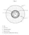
- Figure 1 depicts a cross section of a single-mode fiber with cladding layers at respective radii extending from the center.
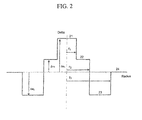
- Figure 2 depicts the nominal refractive index profile of the exemplary single-mode fiber of Figure 1 according to the present invention.
- the fiber (10) of the invention has a central core (11), an intermediate cladding (12) and a depressed cladding (13).
- depressed cladding means a radial portion of the fiber (10) having a refractive index less than the refractive index of the external optical cladding (14).
- the central core (11), the intermediate cladding (12), and the depressed cladding (13) are obtained by chemical vapor deposition in a silica tube.
- the external optical cladding (14) includes the silica tube and the overcladding on the tube.
- the overcladding is generally natural or doped silica, but can also be obtained by any other deposition technique ((vapor axial deposition ("VAD”) or outside vapor deposition (“OVD”)).
- Figure 2 illustrates a refractive index profile for the transmission fiber (10) of Figure 1 .
- the profile of Figure 2 is a set profile, i . e ., representative of the theoretical profile of the fiber, but the fiber actually obtained after fiber drawing of a preform may have a slightly different profile.
- an optical fiber (10) is obtained by preform drawing.
- the preform may be a very high-quality glass tube (pure silica) which eventually forms part of the external optical cladding (14).
- the external optical cladding (14) surrounds the central core (11) and the internal claddings (12, 13) of the fiber. (10).
- This tube can then be overcladded to increase its diameter before going through the fiber-drawing operation on a fiber-drawing tower.
- the tube is generally mounted horizontally and held at both ends by glass bars on a lathe; then the tube is rotated and heated locally for the deposition process determining the composition of the preform. This composition determines the optical characteristics of the future fiber.
- the fiber includes a central core (11) having an index difference ⁇ n 1 with an external cladding (14) functioning as an optical cladding.
- the fiber (10) further includes an intermediate cladding (12) having an index difference ⁇ n 2 with the external optical cladding (14) and a depressed trench cladding (13) having an index difference ⁇ n3 with the external optical cladding (14).
- the refractive indexes in the central core (11), the intermediate cladding (12) and the depressed trench (13) are substantially constant throughout their respective widths, as set forth in Figure 2 .
- Figure 1 illustrates that the width of the core (11) is defined by its radius r 1 and the width of the claddings by their respective external radii, r 2 and r 3 .
- the external optical cladding is denoted as r 4 .
- the refractive index value of the external optical cladding is generally taken as a reference (n g ).
- the index values of the central core (11), the intermediate cladding (12), and the depressed trench cladding (13) are then presented in Figure 2 as index differences ⁇ n 1,2,3 .
- the external optical cladding (14) is composed of silica but this cladding can be doped to increase or reduce its refractive index-for example, to modify the propagation characteristics of the signal.
- Each fiber profile section shown in Figure 2 (21-24) can also be defined on the basis of integrals that link the index variations with the radius of each section of the fiber (10). It is thus possible to define three surface integrals for the fiber (10) of the invention, representative of the surface of the core V 01 , the surface of the intermediate cladding V 02 and the surface of the depressed trench V 03 .
- the expression "surface” is not to be understood geometrically but corresponds to a value taking two dimensions into account.
- V 03 ⁇ r ⁇ 2 r ⁇ 3 ⁇ ⁇ n r . dr ⁇ r 3 - r 2 ⁇ ⁇ ⁇ n 3 .
- volume integrals for the fiber (10) of the invention, representative of the volume of the core V 11 , the volume of the intermediate cladding V 12 and the volume of the depressed trench V 13 .
- volume is not to be understood geometrically but corresponds to a value taking three dimensions into account.
- V 11 2 ⁇ ⁇ 0 r 1 ⁇ ⁇ n r . r . dr ⁇ r 1 2 ⁇ ⁇ ⁇ n 1
- V 12 2 ⁇ ⁇ r 1 r 2 ⁇ ⁇ n r . r .
- Table I shows 9 examples of fiber profiles according to preferred embodiments of the invention in comparison with three SSMF fiber profiles and one fiber profile corresponding to the G.657A and G.657B recommendations (noted as "BIF" for Bend Insensitive Fiber) as well as 13 comparative examples.
- BIF Bend Insensitive Fiber
- the Applicant markets a bend insensitive fiber having a good resistance to bending losses under the trademark range of BendBright.
- the values in the tables correspond to the set profiles for each fiber.
- MPI Multi Path Interference
- the first column of Table I assigns a reference to each example (Ex for Example according to the invention and C. Ex for comparative examples); the next three columns give the values of the radii of the core (11), the intermediate cladding (12), and the depressed trench (13), respectively. The next three columns give the corresponding values of the refractive index differences with the external optical cladding (14). The refractive index values are measured at a wavelength of 633 nanometers. Table I also shows the surface integral and volume integral values of the core (11), the intermediate cladding (12) and the depressed trench (13), as defined above.
- the fiber (10) is a step-index fiber comprising a central core (11), an intermediate cladding (12) and a depressed trench (13). It is noted from Table I that the central core (11) has a radius r 1 between 3.8 ⁇ m and 4.35 ⁇ m and preferably between 3.8 ⁇ m and 4.05 ⁇ m, i . e ., narrower than the core of an SSMF fiber.
- the fiber (10) has an index difference ⁇ n 1 (21) with the external optical cladding (14) between 4.9 x 10 -3 and 5.7 x 10 -3 , i . e ., in the order of or greater than an SSMF fiber.
- the surface integral of the core V 01 is between 19.0 x 10 -3 ⁇ m and 23.0 x 10 -3 ⁇ m, and the volume integral of the core V 11 is between 75 x 10 -3 ⁇ m 2 and 91 x 10 -3 ⁇ m 2 .
- the fiber according to the invention has a depressed trench (13).
- the depressed trench (13) has a large volume and makes it possible to greatly limit the bending losses.
- Table I thus shows that the depressed trench (13) has a radius r 3 between 13.5 ⁇ m and 16 ⁇ m and an index difference ⁇ n 3 (23) with the external optical cladding (14) between -10.0 x 10 -3 and -5.0 x 10 -3 .
- Table I also shows that the surface integral of the depressed trench V 03 , as defined above, is between -55.0 x 10 -3 ⁇ m and -30.0 x 10 -3 ⁇ m, and the volume integral of the depressed trench V 13 , as defined above, is between -1200 x 10 -3 ⁇ m 2 and -750 x 10 -3 ⁇ m 2 .
- the radius of the depressed cladding r 3 can be limited to 15 ⁇ m to further reduce the cost of production of the fiber and all fibers according to the Examples comply herewith.
- the depressed trench (13) can be produced by plasma chemical vapor deposition (PCVD) making it possible to incorporate a large quantity of fluorine in the silica to form deeply depressed claddings.
- the part of the fiber (10) corresponding to the tube and to the PCVD deposition is, however, the most expensive; it is therefore sought to limit this part as much as possible.
- a depressed trench (13) corresponding to the surface and volume criteria defined above makes it possible to achieve a good compromise between greatly reduced bending losses relative to the existing fibers and a sufficiently consistent leakage regime of the LP11 mode at a wavelength of 1260 nanometers.
- a preferred embodiment of the fiber has an intermediate cladding (12) between the central core (11) and the depressed trench (13).
- This intermediate cladding (12) makes it possible to limit the effects of the depressed trench (13) on the propagation of the optical signal in the core.
- Table I shows that the intermediate cladding (12) has a radius r 2 between 8.5 ⁇ m and 9.7 ⁇ m and an index difference ⁇ n 2 (22) with the optical cladding between -0.1 x 10 -3 and 0.6 x 10 -3 .
- Table I shows that the surface integral of the intermediate cladding V 02 , as defined above, is between -0.5 x 10 -3 ⁇ m and 3.0 x 10 -3 ⁇ m.
- the volume integral of the intermediate cladding V 12 is between -6 x 10 -3 ⁇ m 2 and 40 x 10 -3 ⁇ m 2 .
- the central core (11) of a fiber (10) according to the invention is optimized, in combination with the intermediate cladding (12), to guarantee parameters of optical transmission in the fiber in conformity with the G.652 and G657A recommendations, particularly in terms of mode field diameter and chromatic dispersion. This also helps ensure compatibility with fibers of other optical systems.
- Table II shows the optical transmission characteristics for fibers according to the invention.
- the first column repeats the references of Table I.
- the following columns provide, for each fiber profile, the mode field diameter (MFD) values for wavelengths of 1310 nanometers and 1550 nanometers, zero dispersion wavelength (ZDW) and zero dispersion slope (ZDS).
- MFD mode field diameter
- ZDW zero dispersion wavelength
- ZDS zero dispersion slope
- the fiber (10) according to the invention is compatible with fibers corresponding to the criteria of the G.652 recommendation.
- the fiber disclosed herein has a mode field diameter MFD in the standardized range of values from 8.6 ⁇ m to 9.5 ⁇ m at 1310 nanometers, a zero dispersion wavelength between 1300 nanometers and 1324 nanometers, and a zero dispersion slope of less than 0.092 ps/(nm 2 ⁇ km). Each of these values is in accordance with the recommendation G.652.
- the fiber has an effective cut-off wavelength ⁇ ceff (or standard fiber cutoff, third column of Table III) greater than 1300 nanometers, or even greater than 1350 nanometers.
- the effective cut-off wavelength is measured as being the wavelength at which the optical signal is no longer single mode after propagation over two meters of fiber, as defined by Subcommittee 86A of the International Electrotechnical Commission in IEC 60793-44 standard. This increased effective cut-off wavelength value leads to a cable cut-off wavelength value ⁇ cc (or standard cable cutoff fifth column of Table III) between 1200 nanometers and 1260 nanometers.
- the cable cut off wavelength is measured as the wavelength at which the optical signal is no longer single mode after propagation over 22 meters of fiber, as defined by Subcommittee 86A of the International Electrotechnical Commission in IEC 60793-1-44 standard.
- the optical signal is single mode when the attenuation of the LP11 mode is greater than or equal to 19.3 dB.
- the G.652 and G.657 recommendations both impose a maximum value of 1260 nanometers for the cable cut-off wavelength.
- One purpose of the developments disclosed herein is to produce fibers that can be used on all of the transmission bandwidths exploited by optical systems, i . e ., fibers that can be used in single mode propagation from the original bandwidth (OB) which extends from 1260 nanometers to 1360 nanometers, and as far as the ultra-long (UL) bandwidth beyond 1625 nanometers.
- OB original bandwidth
- UL ultra-long
- Table III shows several cut-off wavelength values for fibers according to the invention.
- the first column of Table III repeats the references of Table I.
- the column "Theoretical Fiber Cutoff” provides a theoretical cut-off wavelength value, which corresponds to the transition wavelength between a guided propagation of the LP11 mode and a propagation in leaky mode of this LP11 mode. For working wavelengths beyond this effective cut-off wavelength, the LP11 mode is propagated in leaky mode.
- the column "Standard Fiber Cutoff” corresponds to the effective cut-off wavelength ⁇ ceff as defined by Subcommittee 86A of the International Electrotechnical Commission in IEC 60793-1-44 standard.
- the column “5m Fiber Cutoff” corresponds to the cut-off wavelength measured as the wavelength over which the optical signal is no longer multi mode after propagation over five meters of fiber. This value therefore corresponds to the effective cut-off wavelength measured after propagation over five meters of fiber instead of 2 meters of fiber.
- the column "Standard Cable Cutoff” corresponds to the cable cut-off wavelength ⁇ cc as defined by Subcommittee 86A of the International Electrotechnical Commission in IEC 60793-1-44 standard.
- the cable cut-off wavelength ⁇ cc is determined by positioning the fiber into two 40 millimeters radius loops and by arranging the remainder of the fiber ( i . e ., 21.5 meters of fiber) on a mandrel with a radius of 140 millimeters.
- This cutoff should be 1260 nm or less according to the present invention.
- Comparative examples 7 comply with this requirement but are slightly too high regarding here above straight cable cutoff and hence fall just outside the scope of this invention.
- the column "Straight Cable Cutoff” corresponds to the cable cut-off wavelength by positioning the fiber into two loops each having 40 millimeters radius, and by arranging the remainder of the fiber ( i . e ., 21.5 meters of fiber) virtually straight.
- This cutoff should be 1260 nm or less according to the present invention.
- Comparative examples 9, 10 and 12 comply with this requirement but are slightly too high regarding standard cable cutoff and hence fall just outside the scope of this invention. All comparative examples fall just outside the scope of this invention because they present a standard cutoff a bit higher than 1260 nm or a straight cable cutoff a bit higher than 1260 nm.
- the column "LP11 LL @1260 after 22 m" indicates the leakage losses of the LP11 mode after propagation over 22 meters of virtually straight fiber.
- the column "Length - 19.3dB LP11 LL @1260 nm" indicates the length of fiber required to achieve leakage losses of the LP11 mode equal to 19.3dB with the fiber being kept virtually straight. This indicates at which distance the fiber, arranged virtually straight, is single mode within the meaning of the G.652 and G.657 recommendations.
- the standard effective cut-off wavelength ⁇ ceff i . e ., as measured according to the recommendations of Subcommittee 86A of the International Electrotechnical Commission in IEC 60793-1-44 standard, is greater than 1300 nm.
- the standard cable cut-off wavelength ⁇ cc i . e ., as measured according to the recommendations of Subcommittee 86A of the International Electrotechnical Commission in IEC 60793-44 standard, is between 1200 nanometers and 1260 nanometers, i . e ., complying with the limit of 1260 nanometers imposed by the G.652 and G.657 recommendations.
- the LP11 mode is highly attenuated from a wavelength of 1260 nanometers.
- the "theoretical" fiber cut-off wavelength is less than or equal to 1250 nanometers.
- the higher order LP11 mode is propagated in a leaky mode regime in the original bandwidth, and only the fundamental mode remains guided in the fiber of the invention as from a wavelength of 1260 nanometers.
- the fiber cut-off wavelength is significantly reduced after only 5 meters of propagation in the fiber.
- the cut-off wavelength measured as the wavelength at which the optical signal is no longer single mode after propagation over five meters of fiber, is between 1240 nanometers and 1310 nanometers for a fiber according to the invention.
- the LP11 mode is already well attenuated after 22 meters of propagation. It is noted in particular that the attenuation of the LP11 mode in a fiber (10) according to this invention is greater than the attenuation of the LP11 mode in an SSMF fiber when the fiber is arranged virtually straight. In fact, in an SSMF fiber, it is the bends that make it possible to highly attenuate the LP11 mode. Thus, the fiber has an attenuation of the LP11 mode greater than 5 dB after 22 meters of propagation in straight fiber at a wavelength of 1260 nanometers.
- Table III also shows that the attenuation of at least 19.3 dB of the LP11 mode is achieved relatively rapidly, after less than 22 meters, in accordance with cable cutoff imposed by the recommendation. Moreover, the increase in the effective cut-off wavelength makes it possible to increase the value of the MAC as defined above and consequently to reduce the bending losses.
- Table IV reports bending loss values for preferred embodiments of fibers as disclosed herein.
- the first column of Table IV repeats the references of Table I.
- the next four columns show bending loss values PPC for respective radii of curvature of 15 millimeters, 10 millimeters, 7.5 millimeters and 5 millimeters at a wavelength of 1550 nanometers.
- the next four columns give bending loss values PPC for respective radii of curvature of 15 millimeters, 10 millimeters, 7.5 millimeters and 5 millimeters at a wavelength of 1625 nanometers.
- the last column has a factor of merit FOM representing the order of magnitude of the improvement in the bending losses by the fibers according to this invention relative to the limits imposed by the G.657B recommendation.
- the FOM of Table IV is thus defined as an average of the ratios between the upper limits imposed by the G.657B standard and the bending losses in the fibers of the invention for each radius of curvature measured. All examples present a FOM lower than or equal to 1, thus meaning they all comply with the G.657B bend losses recommendations.
- Table IV reports on the first line the bending loss limit values imposed by the G.657B recommendation for each radius of curvature and for the wavelengths of 1550 nanometers and 1625 nanometers.
- the fiber disclosed above has, for a wavelength of 1550 nanometers, bending losses less than 3 x 10 -3 dB/turn, preferably less than 0.25 x 10 -3 dB/turn for a radius of curvature of 15 millimeters, as compared to a limit of 3 x 10 -3 dB/turn imposed by the G.657B recommendation.
- the fiber further has bending losses less than or equal 3 x 10 -2 , preferably less than or equal to 7.5 x 10 -3 dB/turn for a radius of curvature of 10 millimeters, as compared against a limit of 0.1 dB/turn imposed by the G.657B recommendation.
- the bending losses are less than or equal to 0.05 dB/turn for a radius of curvature of 7.5 millimeters, as against a limit of 0.5 dB/turn imposed by the G.657B recommendation, and bending losses less than 0.15 dB/turn, preferably less than or equal to 0.10 dB/turn for a radius of curvature of 5 millimeters.
- the fiber according to the invention exhibits, for a wavelength of 1625 nanometers, bending losses less than 10 -2 dB/turn, preferably less than 1.5 x 10 -3 dB/turn for a radius of curvature of 15 millimeters, as compared to a limit of 10 -2 dB/turn imposed by the G.657B recommendation.
- the bending losses are less than or equal to 0.1 dB/turn, preferably less than or equal to 25 x 10 -3 dB/turn for a radius of curvature of 10 millimeters, as compared to a limit of 0.2 dB/turn imposed by the G.657B recommendation.
- the fiber exhibits bending losses less than or equal to 0.15 dB/turn, preferably less than or equal to 0.08 dB/turn for a radius of curvature of 7.5 millimeters, as against a limit of 1 dB/turn imposed by the G.657B recommendation, and bending losses less than 0.25 dB/turn for a radius of curvature of 5 millimeters.
- the fibers disclosed herein are well suited to a use in optical systems installed in the subscriber's home, of FTTH type, in which the fiber is subjected to significant bend stresses due to the miniaturization of the optical box or holding the fiber in place with staples.
- the fiber can be placed in particularly compact optical boxes.
- the optical fiber may be arranged with a radius of curvature of less than 15 millimeters, for example, a radius of curvature about 5 millimeters.
- the fiber remains compatible with the fibers of existing systems, in particular in terms of mode field diameter for good fiber-to-fiber coupling.
- the increase in the cut-off wavelength is not detrimental due to a significant attenuation of the LP11 mode from a wavelength of 1260 nanometers.
- microbending can be analyzed according to the IEC fixed-diameter sandpaper drum test ( i . e ., IEC TR62221, Method B, 40-micron grade sandpaper), which provides a microbending stress situation that affects single-mode fibers even at room temperature.
- the IEC TR62221 microbending-sensitivity technical report and standard test procedures e . g ., IEC TR62221, Method B (fixed-diameter sandpaper drum) and Method D (basketweave) are hereby incorporated by reference in their entirety.
- the optical fiber according to the present invention may further include one or more coating layers (e . g ., a primary coating and a secondary coating). At least one of the coating layers - typically the secondary coating - may be colored and/or possess other markings to help identify individual fibers. Alternatively, a tertiary ink layer may surround the primary and secondary coatings.
- a coating layer e . g ., a primary coating and a secondary coating.
- At least one of the coating layers - typically the secondary coating - may be colored and/or possess other markings to help identify individual fibers.
- a tertiary ink layer may surround the primary and secondary coatings.
- optical fiber according to the present invention may be deployed in various structures, such as those exemplary structures disclosed hereinafter.
- one or more of the present optical fibers may be enclosed within a buffer tube.
- optical fiber may be deployed in either a single fiber loose buffer tube or a multi-fiber loose buffer tube.
- multiple optical fibers may be bundled or stranded within a buffer tube or other structure.
- fiber sub bundles may be separated with binders (e.g., each fiber sub-bundle is enveloped in a binder).
- fan-out tubing may be installed at the termination of such loose buffer tubes to directly terminate loose buffered optical fibers with field-installed connectors.
- the buffer tube may tightly surround the outermost optical fiber coating (i.e., tight buffered fiber)or otherwise surround the outermost optical fiber coating or ink layer to provide an exemplary radial clearance of between about 50 and 100 microns (i.e., a semi-tight buffered fiber).
- the buffering may be formed by coating the optical fiber with a curable composition (e.g., a UV-curable material) or a thermoplastic material.
- a curable composition e.g., a UV-curable material
- a thermoplastic material e.g., ethylene glycol dimethacrylate (PE), polymethyl methacrylate (PE), polymethyl methacrylate (PE), polymethyl methacrylate (PE), polymethyl methacrylate, polymethyl methacrylate, polymethyl methacrylate, polymethyl methacrylate, polymethyl methacrylate, polymethyl methacrylate, polymethyl methacrylate, polymethyl methacrylate, polymethyl methacrylate, polymethyl methacrylate, polymethyl methacrylate, polymethyl methacrylate, polymethyl methacrylate, polymethyl methacrylate (e.g., polymethyl methacrylate), polymethyl methacrylate (e.g., polymethyl methacrylate), polymethyl methacrylate (ethacrylate), polymethyl me
- a lubricant may be included between the optical fiber and the buffer tube (e.g., to provide a gliding layer).
- an exemplary buffer tube enclosing optical fibers as disclosed herein may be formed of polyolefins (e.g., polyethylene or polypropylene), including fluorinated polyolefins, polyesters (e.g., polybutylene terephthalate), polyamides (e.g., nylon), as well as other polymeric materials and blends.
- a buffer tube may be formed of one or more layers. The layers may be homogeneous or include mixtures or blends of various materials within each layer.
- the buffer tube may be extruded (e.g., an extruded polymeric material) or pultruded (e.g., a pultruded, fiber-reinforced plastic).
- the buffer tube may include a material to provide high temperature and chemical resistance (e.g., an aromatic material or polysulfone material).
- buffer tubes typically have a circular cross section
- buffer tubes alternatively may have an irregular or non-circular shape (e.g., an oval or a trapezoidal cross section).
- one or more of the present optical fibers may simply be surrounded by an outer protective sheath or encapsulated within a sealed metal tube. In either structure, no intermediate buffer tube is necessarily required.
- optical fibers as disclosed herein may be sandwiched, encapsulated, and/or edge bonded to form an optical fiber ribbon.
- Optical fiber ribbons can be divisible into subunits (e.g., a twelve-fiber ribbon that is splittable into six-fiber subunits).
- a plurality of such optical fiber ribbons may be aggregated to form a ribbon stack, which can have various sizes and shapes.
- optical elements e.g., optical fibers
- optical elements themselves may be designed for increased packing density.
- the optical fiber may possess modified properties, such as improved refractive-index profile, core or cladding dimensions, or primary coating thickness and/or modulus, to improve microbending and macrobending characteristics.
- a rectangular ribbon stack may be formed with or without a central twist (i.e., a "primary twist").
- a ribbon stack is typically manufactured with rotational twist to allow the tube or cable to bend without placing excessive mechanical stress on the optical fibers during winding, installation, and use.
- a twisted (or untwisted) rectangular ribbon stack may be further formed into a coil-like configuration (e.g., a helix) or a wavelike configuration (e.g., a sinusoid).
- the ribbon stack may possess regular "secondary" deformations.
- optical fiber ribbons may be positioned within a buffer tube or other surrounding structure, such as a buffer-tube-free cable.
- a buffer tube or other surrounding structure such as a buffer-tube-free cable.
- a plurality of buffer tubes containing optical fibers may be positioned externally adjacent to and stranded around a central strength member. This stranding can be accomplished in one direction, helically, known as "S” or “Z” stranding, or Reverse Oscillated Lay stranding, known as "S-Z” stranding. Stranding about the central strength member reduces optical fiber strain when cable strain occurs during installation and use.
- two or more substantially concentric layers of buffer tubes may be positioned around a central strength member.
- multiple stranding elements e.g., multiple buffer tubes stranded around a strength member
- a plurality of buffer tubes containing optical fibers may be simply placed externally adjacent to the central strength member (i.e., the buffer tubes are not intentionally stranded or arranged around the central strength member in a particular manner and run substantially parallel to the central strength member).
- the present optical fibers may be positioned with a central buffer tube (i.e., the central buffer tube cable has a central buffer tube rather than a central strength member).
- a central buffer tube cable may position strength members elsewhere.
- metallic or non metallic (e.g., GRP) strength members may be positioned within the cable sheath itself, and/or one or more layers of high-strength yarns (e.g., aramid or non-aramid yarns) may be positioned parallel to or wrapped (e.g., contrahelically) around the central buffer tube (i.e., within the cable's interior space).
- strength members can be included within the buffer tube's casing.
- the optical fibers may be placed within a slotted core cable.
- a slotted core cable optical fibers, individually or as a fiber ribbon, may be placed within pre-shaped helical grooves (i.e., channels) on the surface of a central strength member, thereby forming a slotted core unit.
- the slotted core unit may be enclosed by a buffer tube.
- One or more of such slotted core units may be placed within a slotted core cable.
- a plurality of slotted core units may be helically stranded around a central strength member.
- the optical fibers may also be stranded in a maxitube cable design, whereby the optical fibers are stranded around themselves within a large multi-fiber loose buffer tube rather than around a central strength member.
- the large multi-fiber loose buffer tube is centrally positioned within the maxitube cable.
- such maxitube cables may be deployed in optical ground wires (OPGW).
- multiple buffer tubes may be stranded around themselves without the presence of a central member. These stranded buffer tubes may be surrounded by a protective tube.
- the protective tube may serve as the outer casing of the fiber optic cable or may be further surrounded by an outer sheath. The protective tube may tightly or loosely surround the stranded buffer tubes.
- additional elements may be included within a cable core.
- copper cables or other active, transmission elements may be stranded or otherwise bundled within the cable sheath.
- Passive elements may also be placed within the cable core, such as between the interior walls of the buffer tubes and the enclosed optical fibers.
- passive elements may be placed outside the buffer tubes between the respective exterior walls of the buffer tubes and the interior wall of the cable jacket, or, within the interior space of a buffer-tube-free cable.
- yarns, nonwovens, fabrics e.g., tapes
- foams, or other materials containing water-swellable material and/or coated with water swellable materials may be employed to provide water blocking and/or to couple the optical fibers to the surrounding buffer tube and/or cable jacketing (e.g., via adhesion, friction, and/or compression).
- SAPs super absorbent polymers
- Exemplary water-swellable elements are disclosed in commonly assigned U.S. Patent Application Publication No. US 2007/0019915 A1 and its related U.S. Patent Application No. 11/424,112 for a Water Swellable Tape, Adhesive-Backed for Coupling When Used Inside a Buffer Tube (Overton et al.), each of which is hereby incorporated by reference in its entirety.
- an adhesive e.g., a hot-melt adhesive or curable adhesive, such as a silicone acrylate cross-linked by exposure to actinic radiation
- a passive element e.g., water-swellable material
- An adhesive material may also be used to bond the water-swellable element to optical fibers within the buffer tube. Exemplary arrangements of such elements are disclosed in commonly assigned U.S. Patent Application Publication No. US 2008/0145010 A1 for a Gel-Free Buffer Tube with Adhesively Coupled Optical Element (Overton et al.), which is hereby incorporated by reference in its entirety.
- the buffer tubes may also contain a thixotropic composition (e.g., grease or grease-like gels) between the optical fibers and the interior walls of the buffer tubes.
- a thixotropic composition e.g., grease or grease-like gels
- the thixotropic filling grease mechanically (i.e., viscously) couples the optical fibers to the surrounding buffer tube.
- the present optical fibers may be deployed in dry cable structures (i.e., grease-free buffer tubes).
- Exemplary buffer tube structures that are free from thixotropic filling greases are disclosed in commonly assigned U.S. Patent Application No. 12/146,588 for a Coupling Composition for Optical Fiber Cables, filed June 26, 2008, (Parris et al.), which is hereby incorporated by reference in its entirety.
- Such buffer tubes employ coupling compositions formed from a blend of high-molecular weight elastomeric polymers (e.g., about 35 weight percent or less) and oils (e.g., about 65 weight percent or more) that flow at low temperatures.
- the coupling composition e.g., employed as a cohesive gel or foam
- the coupling composition is typically dry and, therefore, less messy during splicing.
- a cable enclosing optical fibers as disclosed herein may have a sheath formed from various materials in various designs.
- Cable sheathing may be formed from polymeric materials such as, for example, polyethylene, polypropylene, polyvinyl chloride (PVC), polyamides (e.g., nylon), polyester (e.g., PBT), fluorinated plastics (e.g., perfluorethylene propylene, polyvinyl fluoride, or polyvinylidene difluoride), and ethylene vinyl acetate.
- the sheath and/or buffer tube materials may also contain other additives, such as nucleating agents, flame retardants, smoke-retardants, antioxidants, UV absorbers, and/or plasticizers.
- the cable sheathing may be a single jacket formed from a dielectric material (e.g., non-conducting polymers), with or without supplemental structural components that may be used to improve the protection (e.g., from rodents) and strength provided by the cable sheath.
- a dielectric material e.g., non-conducting polymers
- supplemental structural components that may be used to improve the protection (e.g., from rodents) and strength provided by the cable sheath.
- metallic e.g., steel
- Metallic or fiberglass reinforcing rods e.g., GRP
- GRP fiberglass reinforcing rods
- aramid, fiberglass, or polyester yarns may be employed under the various sheath materials (e.g., between the cable sheath and the cable core), and/or ripcords may be positioned, for example, within the cable sheath.
- optical fiber cable sheaths typically have a circular cross section, but cable sheaths alternatively may have an irregular or non-circular shape (e.g., an oval, trapezoidal, or flat cross-section).
- the optical fiber according to the present invention may be incorporated into single-fiber drop cables, such as those employed for Multiple Dwelling Unit (MDU) applications.
- MDU Multiple Dwelling Unit
- the cable jacketing must exhibit crush resistance, abrasion resistance, puncture resistance, thermal stability, and fire resistance as required by building codes.
- An exemplary material for such cable jackets is thermally stable, flame-retardant polyurethane (PUR), which mechanically protects the optical fibers yet is sufficiently flexible to facilitate easy MDU installations.
- PUR flame-retardant polyurethane
- a flame-retardant polyolefin or polyvinyl chloride sheath may be used.
- a strength member is typically in the form of a rod or braided/helically wound wires or fibers, though other configurations will be within the knowledge of those having ordinary skill in the art.
- Optical fiber cables containing optical fibers as disclosed may be variously deployed, including as drop cables, distribution cables, feeder cables, trunk cables, and stub cables, each of which may have varying operational requirements (e.g., temperature range, crush resistance, UV resistance, and minimum bend radius).
- Such optical fiber cables may be installed within ducts, microducts, plenums, or risers.
- an optical fiber cable may be installed in an existing duct or microduct by pulling or blowing (e.g., using compressed air).
- An exemplary cable installation method is disclosed in commonly assigned U.S. Patent Application Publication No. 2007/0263960 for a Communication Cable Assembly and Installation Method (Lock et al.), and U.S. Patent Application No. 12/200,095 for a Modified Pre-Ferrulized Communication Cable Assembly and Installation Method, filed August 28, 2008, (Griffioen et al.), each of which is incorporated by reference in its entirety.
- buffer tubes containing optical fibers may be stranded (e.g., around a central strength member).
- an optical fiber cable's protective outer sheath may have a textured outer surface that periodically varies lengthwise along the cable in a manner that replicates the stranded shape of the underlying buffer tubes.
- the textured profile of the protective outer sheath can improve the blowing performance of the optical fiber cable.
- the textured surface reduces the contact surface between the cable and the duct or microduct and increases the friction between the blowing medium (e.g., air) and the cable.
- the protective outer sheath may be made of a low coefficient-of-friction material, which can facilitate blown installation.
- the protective outer sheath can be provided with a lubricant to further facilitate blown installation.
- the outer cable diameter of an optical fiber cable should be no more than about seventy to eighty percent of the duct's or microducts inner diameter.
- Compressed air may also be used to install optical fibers according to the present invention in an air blown fiber system.
- an air blown fiber system a network of unfilled cables or microducts is installed prior to the installation of optical fibers.
- Optical fibers may subsequently be blown into the installed cables as necessary to support the network's varying requirements.
- the optical fiber cables may be directly buried in the ground or, as an aerial cable, suspended from a pole or pylon.
- An aerial cable may be self-supporting or secured or lashed to a support (e.g., messenger wire or another cable).
- Exemplary aerial fiber optic cables include overhead ground wires (OPGW), all-dielectric self-supporting cables (ADSS), all dielectric lash cables (AD-Lash), and figure-eight cables, each of which is well understood by those having ordinary skill in the art.
- OPGW overhead ground wires
- ADSS all-dielectric self-supporting cables
- AD-Lash all dielectric lash cables
- figure-eight cables each of which is well understood by those having ordinary skill in the art.
- Figure-eight cables and other designs can be directly buried or installed into ducts, and may optionally include a toning element, such as a metallic wire, so that they can be found with a metal detector.
- optical fibers may be further protected by an outer cable sheath
- the optical fiber itself may be further reinforced so that the optical fiber may be included within a breakout cable, which allows for the individual routing of individual optical fibers.
- Optical fiber connections are required at various points in the network.
- Optical fiber connections are typically made by fusion splicing, mechanical splicing, or mechanical connectors.
- the mating ends of connectors can be installed to the fiber ends either in the field (e.g., at the network location) or in a factory prior to installation into the network.
- the ends of the connectors are mated in the field in order to connect the fibers together or connect the fibers to the passive or active components.
- certain optical fiber cable assemblies e.g., furcation assemblies
- optical fiber cables may include supplemental equipment.
- an amplifier may be included to improve optical signals.
- Dispersion compensating modules may be installed to reduce the effects of chromatic dispersion and polarization mode dispersion.
- Splice boxes, pedestals, and distribution frames, which may be protected by an enclosure, may likewise be included. Additional elements include, for example, remote terminal switches, optical network units, optical splitters, and central office switches.
- a cable containing optical fibers according to the present invention may be deployed for use in a communication system (e.g., networking or telecommunications).
- a communication system may include fiber optic cable architecture such as fiber-to-the-node (FTTN), fiber-to-the-telecommunications enclosure (FTTE), fiber-to-the-curb (FTTC), fiber-to-the-building (FTTB), and fiber-to-the-home (FTTH), as well as long-haul or metro architecture.
- FTTN fiber-to-the-node
- FTTE fiber-to-the-telecommunications enclosure
- FTTC fiber-to-the-curb
- FTTB fiber-to-the-building
- FTTH fiber-to-the-home
- optical fibers according to the present invention may be used in other applications, including, without limitation, fiber optic sensors or illumination applications (e.g., lighting).
Abstract
Description
- The present invention relates to the field of optical fiber transmissions, and more specifically, to a fiber having greatly reduced bending losses.
- For optical fibers, the refractive index profile is generally set forth in terms of the difference in value between two points on the graph of the function associating the refractive index with the radius of the fiber. Conventionally, the distance r to the centre of the fiber is shown along the x-axis of the profile. The difference between the refractive index at distance r and the refractive index of the external fiber cladding is shown along the y-axis (
Figure 2 , references 21-24). The external cladding functions as an optical cladding and has a substantially constant refractive index; this optical cladding is generally composed of pure silica but can also contain one or more dopants. The optical fiber refractive index profile is referred to as a "step" profile, a "trapezoidal" profile, or a "triangular" profile for graphs having the respective shapes of a step, a trapezoid, or a triangle. These curves are generally representative of the theoretical or reference index profile (i.e., set profile) of the fiber. Fiber manufacturing constraints may lead to a slightly different profile in the actual fiber. - An optical fiber is conventionally composed of (i) an optical core, having the function of transmitting and optionally amplifying an optical signal, and (ii) an optical cladding, having the function of confining the optical signal in the core. For this purpose, the refractive indexes of the core (nc) and of the cladding (ng) are such that nc > ng. As is well known in the art, the propagation of an optical signal in a single-mode optical fiber is broken down into a fundamental mode (known as LP01) guided in the core, and into secondary modes guided over a certain radius in the core-cladding assembly.
- Conventionally, step-index fibers, also called SMF fibers ("Single Mode Fibers") are used as line fibers for optical fiber transmission systems. These fibers exhibit a chromatic dispersion and a chromatic dispersion slope corresponding to specific telecommunication recommendations.
- For the requirements of compatibility between the optical systems from different manufacturers, the International Telecommunication Union (ITU) has defined a recommendation with a norm, referenced ITU-T G.652, which must be met by a Standard Single Mode Fiber (SSMF).
- This G.652 recommendation for transmission fibers recommends inter alia, a nominal range of 8.6 microns to 9.5 microns for the Mode Field Diameter (MFD) at a wavelength of 1310 nanometers which can vary with +/- 0.4 µm due to manufacturing tolerances; a maximum of 1260 nanometers for the cable cut-off wavelength; a range of 1300 nanometers to 1324 nanometers for the dispersion cancellation wavelength (denoted λ0); and a maximum chromatic dispersion slope of 0.092 ps/(nm2·km) (i.e., ps/nm2/km).
- The cable cut-off wavelength is conventionally measured as the wavelength at which the optical signal is no longer single mode after propagation over 22 meters of fiber, such as defined by Subcommittee 86A of the International Electrotechnical Commission in the IEC 60793-1-44 standard.
- In most cases, the secondary mode most resistant to bending losses is the LP11 mode. The cable cut-off wavelength is, therefore, the wavelength beyond which the LP11 mode is sufficiently weakened after propagation over 22 meters of fiber. The method proposed by the standard involves considering that the optical signal is single mode when the attenuation of the LP11 mode is greater than or equal to 19.3 dB.
- Moreover, for a given fiber, a so-called MAC value is defined as the ratio of the mode field diameter of the fiber at 1550 nanometers over the effective cut-off wavelength λceff. The cut-off wavelength is conventionally measured as the wavelength at which the optical signal is no longer single mode after propagation over two meters of fiber, as defined by Subcommittee 86A of the International Electrotechnical Commission in standard IEC 60793-1-44. The MAC constitutes a parameter for assessing the performances of the fiber, in particular for finding a compromise between the mode field diameter, the effective cut-off wavelength and the bending losses.
- European Patent Application No.
1,845,399 and European Patent Application No.1,785,754 , illustrate the Applicant's experimental results. These prior applications establish a relationship between the value of the MAC at a wavelength of 1550 nanometers and the bending losses at a wavelength of 1625 nanometers with a radius of curvature of 15 millimeters in a standard step-index fiber SSMF. Each of these European patent applications is hereby incorporated by reference in its entirety. Furthermore, each application establishes that the value of the MAC influences the bending losses of the fiber and that reducing the MAC reduces these bending losses. Reducing the mode field diameter and/or increasing the effective cut-off wavelength reduces the MAC value but may lead to noncompliance with the G.652 recommendation, making the fiber commercially incompatible with some transmission systems. - The reduction of the bending losses, while retaining certain optical transmission parameters, constitutes a challenge for applications of fibers intended for optical fiber systems to the user, called FTTH for Fiber-To-The-Home.
- The International Telecommunications Union ITU has also defined recommendations referenced ITU-T G.657A and ITU-T G.657B, which must be met by the optical fibers intended for FTTH applications, particularly in terms of resistance to bending losses. The G.657A recommendation imposes limits on values for bending losses but seeks, above all, to preserve compatibility with the G.652 recommendation, particularly in terms of mode field diameter MFD and chromatic dispersion. On the other hand, the G.657B recommendation imposes strict bending loss limits, particularly for (i) bending losses less than 0.003 dB/turn at a wavelength of 1550 nanometers for a radius of curvature of 15 millimeters and (ii) bending losses less than 0.01 dB/turn at a wavelength of 1625 nanometers for a radius of curvature of 15 millimeters.
- European Patent Application No.
1,845,399 and European Patent Application No.1,785,754 propose fiber profiles having limited bending losses, corresponding in particular to the criteria of the G.657A and G.657B recommendations. The profiles described in these European patent applications, however, make it possible to achieve only the bending loss limits imposed by the G.657B recommendation. -
U.S. Patent No. 7,164,835 andU.S. Patent Application Publication No. 2007/0147756 , each of which is hereby incorporated by reference in its entirety, also describe fiber profiles exhibiting limited bending losses. The fibers of these U.S. Patents, however, correspond only to the criteria of the G.657A and G.657B recommendations, particularly in terms of mode field diameter and chromatic dispersion. - At the present, for certain applications, the reduction of the bending losses is essential, especially when the fiber is intended to be stapled or coiled in a miniaturized optical box.
- Hole-assisted fiber technology makes it possible to achieve excellent performances in terms of bending losses, but this technology is complex and expensive to implement and cannot be used for fibers intended for the FTTH systems, which are low-cost systems.
- The applicant markets a bend insensitive fiber having a good resistance to bending losses under the trademark of BendBright-XS. This range of fibers is fully compliant with ITU-T G.652 and G.657B recommendations and presents typical bend losses of 0.3 dB/turn at 5 mm radius of curvature at 1550 nm. A need therefore exists for an optical fiber having a typical resistance to bending losses which is clearly better for the 5 mm radius of curvature than the typical level of the above-mentioned marketed fiber. The fiber meeting this criterion should also remain fully compliant with the G.652 recommendation in terms of transmission profile and, in particular, mode field diameter and cable cutoff. This appreciable improvement of bending losses may be achieved to the detriment of a higher cut-off wavelength, provided that (i) the directly higher order LP11 mode is sufficiently attenuated, and (ii) that the length of fiber required for the attenuation of the LP11 mode to reach 19.3 dB at a wavelength of 1260 nanometers is less than 22 meters, thus ensuring cable cutoff lower or equal to 1260 nm. The fiber meeting this criterion should also remain fully compliant with the G.657B recommendation.
- For purposes described above, the invention includes a fiber with a central core, an intermediate cladding, and a depressed trench surrounded by an external optical cladding. The refractive index profile is optimized to improve the bending losses by a factor of ten relative to the constraints imposed by the G.657B recommendation, while retaining a mode field diameter compatible with the G.652 recommendation and ensuring a sufficient attenuation of the LP11 mode.
- In particular, the surface of the core, as well as the surface and the volume of the depressed trench, are optimized to improve the bending losses considerably. In the context of the invention, the surface of the core or the surface of the depressed trench should not extend geometrically but should correspond to values taking two dimensions into account - the product of the radius and the index difference. Similarly, the volume of the depressed trench corresponds to a value taking three dimensions into account - the product of the square of the radius and the index difference.
- The invention proposes more particularly a single mode optical fiber, including, from the center toward the periphery, a central core, an intermediate cladding, a depressed trench, and an external optical cladding. The central core has a radius r1 and a positive index difference Δn1 with the external optical cladding. The intermediate cladding has a radius r2 and a positive index difference Δn2 with the external optical cladding. The difference Δn2 is less than the index difference Δn1 of the core. The depressed trench has a radius r3 and a negative index difference Δn3 with the external optical cladding. The fiber of this invention is further characterized in that it has (i) a nominal mode field diameter (MFD) between 8.6 µm and 9.5 µm at a wavelength of 1310 nanometers and (ii) bending losses less than 0.15 dB/turn for a radius of curvature of 5 millimeters at a wavelength of 1550 nanometers and a cable cut-off wavelength of less than or equal to 1260 nm, measured as the wavelength at which the attenuation of the LP11 mode is greater than or equal to 19.3 dB after propagation over twenty-two meters of fiber, the fiber being either straight conditioned or conditioned around a 140mm curvature radius mandrel.
- According to one embodiment of a fiber according to this invention, the surface integral of the central core (V01), defined as

is between 19.0 x 10⁻³ µm and 23.0 0 x 10-3 µm and preferably between 20.0 x 10⁻³ µm and 23.0 x 10⁻³ µm. In a further preferred embodiment the surface integral of the central core (V01) is between 20.0 x 10⁻³ µm and 21.5 x 10⁻³ µm since this gives rise to optimal optical properties of the present fiber. - According to one embodiment of a fiber according to this invention, the surface integral of the depressed trench (V03), defined as

is between -55.0 x 10⁻³ µm and -30.0 x 10⁻³ µm. In a further preferred embodiment the the surface integral of the depressed trench (V03) is between -42.5 x 10⁻³ µm and -32.5 x 10⁻³ µm since this gives rise to optimal optical properties of the present fiber. - According to one embodiment of a fiber according to this invention, the volume integral of the depressed trench (V13), defined as,

is between -1200x 10-3 µm2 and -750 x 10-3 µm2. In a further preferred embodiment the volume integral of the depressed trench (V13) is between -1000x 10-3 µm2 and -750 x 10-3 µm2 since this gives rise to optimal optical properties of the present fiber. - In preferred embodiments, the fiber has physical properties and operational parameters with improved resistance to bending losses. For instance, the fiber has an effective cut-off wavelength λceff greater than 1300 nanometers, the effective cut-off wavelength being measured as the wavelength at which the optical signal becomes single mode after propagation over two meters of fiber. The fiber has, for a wavelength of 1550 nanometers, bending losses less than or equal to 0.003 dB/turn for a radius of curvature of 15 millimeters, bending losses less than or equal to 3 x 10⁻² dB/turn, preferably 7.5 x 10⁻³ dB/turn for a radius of curvature of 10 millimeters, bending losses less than or equal to 0.05 dB/turn for a radius of curvature of 7.5 millimeters, and bending losses less than 0.15 dB/turn, preferably less than 0.10 dB/turn for a radius of curvature of 5 millimeters.
- The fiber disclosed herein also shows reduced bending losses at higher wavelengths. For example, at a wavelength of 1625 nanometers, the fiber has bending losses less than 10-2 dB/turn, preferably less than 1.5 x 10⁻³ dB/turn for a radius of curvature of 15 millimeters, bending losses less than or equal to 0.1 dB/turn, preferably less than or equal to 25 x 10-3 dB/turn for a radius of curvature of 10 millimeters, bending losses less than or equal to 0.15 dB/turn, preferably less than or equal to 0.08 dB/turn for a radius of curvature of 7.5 millimeters, and bending losses less than or equal to 0.25 dB/turn for a radius of curvature of 5 millimeters. Accordingly, in a preferred embodiment, the fiber has a cut-off wavelength between 1240 nanometers and 1310 nanometers, with the cutoff wavelength measured as the wavelength at which the optical signal is no longer single mode after propagation over five meters of fiber. Cut-off wavelength is distinguished from cable cut-off, measured as the wavelength at which the attenuation of the LP11 mode is greater than or equal to 19.3 dB after propagation over 22 meters of fiber. The fiber has a cable cut-off wavelength less than or equal to 1260 nanometers.
- A fourth cutoff definition at issue here is the theoretical cut-off wavelength defined as the wavelength from which the LP11 mode is propagated in leaky mode. In one embodiment, the fiber has a theoretical cut-off wavelength less than or equal to 1250 nanometers. The fiber has an attenuation of the LP11 mode greater than 5 dB after propagation over 22 meters of fiber at a wavelength of 1260 nanometers.
- The operational parameters described above result from preferred physical properties of the fiber. In one embodiment, the central core of the fiber has a radius between 3.8 µm and 4.35 µm; the intermediate cladding has a radius between 8.5 µm and 9.7 µm; the depressed trench has a radius between 13.5 µm and 16 µm, which can be less than or equal to 15 µm. The central core preferably has a refractive index difference (Δn1) with the external optical cladding between 4.9 x 10⁻³ and 5.7 x 10⁻³.
- As noted above, the refractive index profile of a fiber is plotted in terms of the difference between refractive index values at points on the radius of the fiber and the external optical cladding. The intermediate cladding has an index difference with the optical cladding between -0.1 x 10⁻³ and 0.6 x 10⁻³. The depressed trench has an index difference with the optical cladding between -10.0 x 10⁻³ and -5.0
x 10-3. The fiber has a zero chromatic dispersion wavelength between 1300 nanometers and 1324 nanometers; the fiber has a chromatic dispersion slope value at the zero chromatic dispersion wavelength of less than 0.092 ps/(nm2·km). - The invention also relates to an optical box receiving at least one portion of fiber disclosed herein. In such a box, the fiber can be arranged with a radius of curvature less than 15 millimeters, which can be on the order of 5 millimeters. The invention also relates to an optical fiber system to the subscriber's home (FTTH) comprising at least one portion of fiber according to the invention.
- The foregoing, as well as other characteristics and advantages of the present invention, and the manner in which the same are accomplished, are further specified within the following detailed description and its accompanying drawings.
-
Figure 1 depicts a cross section of a single-mode fiber with cladding layers at respective radii extending from the center. -
Figure 2 depicts the nominal refractive index profile of the exemplary single-mode fiber ofFigure 1 according to the present invention. - The fiber (10) of the invention has a central core (11), an intermediate cladding (12) and a depressed cladding (13). For purposes herein and without limiting the scope of the invention, depressed cladding means a radial portion of the fiber (10) having a refractive index less than the refractive index of the external optical cladding (14). Typically, the central core (11), the intermediate cladding (12), and the depressed cladding (13) are obtained by chemical vapor deposition in a silica tube. The external optical cladding (14) includes the silica tube and the overcladding on the tube. In preferred embodiments, the overcladding is generally natural or doped silica, but can also be obtained by any other deposition technique ((vapor axial deposition ("VAD") or outside vapor deposition ("OVD")).
-
Figure 2 illustrates a refractive index profile for the transmission fiber (10) ofFigure 1 . The profile ofFigure 2 is a set profile, i.e., representative of the theoretical profile of the fiber, but the fiber actually obtained after fiber drawing of a preform may have a slightly different profile. - In a manner known in the art per se, an optical fiber (10) is obtained by preform drawing. By way of example, the preform may be a very high-quality glass tube (pure silica) which eventually forms part of the external optical cladding (14). The external optical cladding (14) surrounds the central core (11) and the internal claddings (12, 13) of the fiber. (10). This tube can then be overcladded to increase its diameter before going through the fiber-drawing operation on a fiber-drawing tower. For the production of the preform, the tube is generally mounted horizontally and held at both ends by glass bars on a lathe; then the tube is rotated and heated locally for the deposition process determining the composition of the preform. This composition determines the optical characteristics of the future fiber.
- The fiber includes a central core (11) having an index difference Δn1 with an external cladding (14) functioning as an optical cladding. The fiber (10) further includes an intermediate cladding (12) having an index difference Δn2 with the external optical cladding (14) and a depressed trench cladding (13) having an index difference Δn3 with the external optical cladding (14). The refractive indexes in the central core (11), the intermediate cladding (12) and the depressed trench (13) are substantially constant throughout their respective widths, as set forth in
Figure 2 .Figure 1 illustrates that the width of the core (11) is defined by its radius r1 and the width of the claddings by their respective external radii, r2 and r3. The external optical cladding is denoted as r4. - In order to define a set refractive index profile for an optical fiber, the refractive index value of the external optical cladding is generally taken as a reference (ng). The index values of the central core (11), the intermediate cladding (12), and the depressed trench cladding (13) are then presented in
Figure 2 as index differences Δn1,2,3. Generally, the external optical cladding (14) is composed of silica but this cladding can be doped to increase or reduce its refractive index-for example, to modify the propagation characteristics of the signal. - Each fiber profile section shown in
Figure 2 (21-24) can also be defined on the basis of integrals that link the index variations with the radius of each section of the fiber (10). It is thus possible to define three surface integrals for the fiber (10) of the invention, representative of the surface of the core V01, the surface of the intermediate cladding V02 and the surface of the depressed trench V03. The expression "surface" is not to be understood geometrically but corresponds to a value taking two dimensions into account. These three surface integrals can be expressed as follows:


- Similarly, it is possible to define three volume integrals for the fiber (10) of the invention, representative of the volume of the core V11, the volume of the intermediate cladding V12 and the volume of the depressed trench V13. The expression "volume" is not to be understood geometrically but corresponds to a value taking three dimensions into account. These three volume integrals can be expressed as follows:


- Table I (below) shows 9 examples of fiber profiles according to preferred embodiments of the invention in comparison with three SSMF fiber profiles and one fiber profile corresponding to the G.657A and G.657B recommendations (noted as "BIF" for Bend Insensitive Fiber) as well as 13 comparative examples. The Applicant markets a bend insensitive fiber having a good resistance to bending losses under the trademark range of BendBright. The values in the tables correspond to the set profiles for each fiber.
- All profiles were also designed to ensure a Multi Path Interference (MPI) level lower than -30 dB, which ensures a full compatibility with any properly installed system networks including Access Network and Fiber to the Home. MPI is defined in W. Zheng et al., "Measurement and System Impact of Multipath Interference From Dispersion Compensating Fiber Modules", IEEE Transactions on Instrumentation and Measurement, 2004, 53, pp15-23) and its particular measurement considerations detailed in S. Ramachandran et Al., "Measurement of Multipath Interference in the Coherent Crosstalk Regime", IEEE Photonics Technology Letters, 2003, 15, pp 1171-1173.
- The first column of Table I assigns a reference to each example (Ex for Example according to the invention and C. Ex for comparative examples); the next three columns give the values of the radii of the core (11), the intermediate cladding (12), and the depressed trench (13), respectively. The next three columns give the corresponding values of the refractive index differences with the external optical cladding (14). The refractive index values are measured at a wavelength of 633 nanometers. Table I also shows the surface integral and volume integral values of the core (11), the intermediate cladding (12) and the depressed trench (13), as defined above.
Table I r1 r2 r3 Dn1 Dn2 Dn3 V01 V02 V03 V11 V12 V13 (µm) (µm) (µm) [10-3] [10-3] [10-3] (µm) [10-3] (µm) [10-3] (µm) [10-3] (µm2) [10-3] (µm2) [10-3] (µm2) [10-3] BIF 3.93 9.38 14.72 5.26 0.13 -5.01 20.7 0.7 -26.8 81.1 9.4 -645 SSMF1 4.35 13.92 5.00 -0.20 21.8 -1.9 0.0 94.6 -35.0 0 SSMF2 4.51 13.92 5.00 -0.20 22.5 -1.9 0.0 101.5 -34.7 0 SSMF3 4.55 13.92 5.24 -0.20 23.8 -1.9 0.0 108.4 -34.6 0 C.Ex1 3.82 9.01 13.55 5.67 0.57 -9.63 21.7 2.9 -43.7 82.8 37.7 -986 C.Ex2 3.96 8.61 13.86 5.58 0.31 -7.87 22.1 1.4 -41.3 87.6 17.9 -928 C.Ex3 3.92 8.78 13.84 5.55 0.32 -8.75 21.7 1.5 -44.3 85.2 19.7 -1002 C.Ex4 3.88 9.09 14.35 5.62 0.34 -7.84 21.8 1.8 -41.2 84.5 23.1 -965 C.Ex5 3.93 9.30 14.48 5.30 0.51 -7.76 20.8 2.7 -40.1 81.7 36.0 -955 C.Ex6 3.93 9.28 14.47 5.31 0.53 -7.51 20.9 2.8 -39.0 82.0 37.5 -926 C.Ex7 3.93 8.50 15.00 5.48 0.50 -5.00 21.5 2.3 -32.5 84.6 28.4 -764 C.Ex8 3.93 9.25 13.65 5.37 0.50 -9.90 21.1 2.7 -43.5 83.0 35.1 -997 C.Ex9 3.93 8.50 15.50 5.33 0.51 -5.00 21.0 2.3 -35.0 82.4 28.8 -840 C.Ex10 3.93 9.27 13.65 5.31 0.52 -9.80 20.9 2.8 -42.9 82.1 36.9 -983 C.Ex11 3.94 9.25 13.54 5.30 0.56 -9.87 20.9 3.0 -42.3 82.3 39.2 -964 C.Ex12 3.95 9.29 13.91 5.30 0.50 -8.93 20.9 2.7 -41.2 82.6 35.4 -957 C.Ex13 3.93 8.50 15.50 5.32 0.57 -5.00 20.9 2.6 -35.0 82.1 32.2 -840 Ex1 3.90 9.23 14.34 4.94 0.35 -7.15 19.3 1.9 -36.5 75.1 24.5 -861 Ex2 3.91 9.23 14.34 5.14 0.10 -7.15 20.1 0.5 -36.5 78.6 7.0 -861 Ex3 3.91 9.23 14.81 5.14 0.10 -7.15 20.1 0.5 -39.9 78.6 7.0 -959 Ex4 3.91 9.23 14.34 5.29 -0.06 -7.15 20.7 -0.3 -36.5 30.9 -4.2 -861 Ex5 3.91 9.23 14.81 5.29 -0.06 -7.15 20.7 -0.3 -39.9 30.9 -4.2 -959 Ex6 3.93 9.26 13.53 5.34 0.51 -9.74 21.0 2.7 -41.6 82.3 36.0 -949 Ex7 3.93 9.25 13.53 5.31 0.50 -9.93 20.8 2.7 -42.5 81.9 35.3 -967 Ex8 3.94 8.50 15.00 5.43 0.50 -5.00 21.4 2.3 -32.5 84.3 28.6 -764 Ex9 3.94 9.26 13.50 5.33 0.51 -9.88 21.0 2.7 -41.9 82.8 35.5 -954 - The fiber (10) according to the embodiment in
Figures 1 and2 according to the invention is a step-index fiber comprising a central core (11), an intermediate cladding (12) and a depressed trench (13). It is noted from Table I that the central core (11) has a radius r1 between 3.8 µm and 4.35 µm and preferably between 3.8 µm and 4.05 µm, i.e., narrower than the core of an SSMF fiber. The fiber (10) has an index difference Δn1 (21) with the external optical cladding (14) between 4.9 x 10⁻³ and 5.7 x 10⁻³, i.e., in the order of or greater than an SSMF fiber. The surface integral of the core V01 is between 19.0 x 10⁻³ µm and 23.0 x 10⁻³ µm, and the volume integral of the core V11 is between 75 x 10-3 µm2 and 91 x 10-3 µm2. - It is also noted from Table I that the fiber according to the invention has a depressed trench (13). The depressed trench (13) has a large volume and makes it possible to greatly limit the bending losses. Table I thus shows that the depressed trench (13) has a radius r3 between 13.5 µm and 16 µm and an index difference Δn3 (23) with the external optical cladding (14) between -10.0 x 10⁻³ and -5.0
x 10-3. Table I also shows that the surface integral of the depressed trench V03, as defined above, is between -55.0 x 10⁻³ µm and -30.0 x 10⁻³ µm, and the volume integral of the depressed trench V13, as defined above, is between -1200x 10-3 µm2 and -750 x 10-3 µm2. - According to a preferred embodiment, the radius of the depressed cladding r3 can be limited to 15 µm to further reduce the cost of production of the fiber and all fibers according to the Examples comply herewith. In fact, the depressed trench (13) can be produced by plasma chemical vapor deposition (PCVD) making it possible to incorporate a large quantity of fluorine in the silica to form deeply depressed claddings. The part of the fiber (10) corresponding to the tube and to the PCVD deposition is, however, the most expensive; it is therefore sought to limit this part as much as possible. It is also possible to envisage producing the depressed trench (13) by incorporation of micro-holes or micro-bubbles rather than by fluorine doping. Fluorine doping, however, remains easier to control for industrial production than the incorporation of micro-bubbles.
- A depressed trench (13) corresponding to the surface and volume criteria defined above makes it possible to achieve a good compromise between greatly reduced bending losses relative to the existing fibers and a sufficiently consistent leakage regime of the LP11 mode at a wavelength of 1260 nanometers.
- It is also noted from Table I that a preferred embodiment of the fiber has an intermediate cladding (12) between the central core (11) and the depressed trench (13). This intermediate cladding (12) makes it possible to limit the effects of the depressed trench (13) on the propagation of the optical signal in the core. Table I shows that the intermediate cladding (12) has a radius r2 between 8.5 µm and 9.7 µm and an index difference Δn2 (22) with the optical cladding between -0.1 x 10⁻³ and 0.6 x 10⁻³. Table I shows that the surface integral of the intermediate cladding V02, as defined above, is between -0.5 x 10⁻³ µm and 3.0 x 10⁻³ µm. The volume integral of the intermediate cladding V12, as defined above, is between -6 x 10⁻³ µm2 and 40 x 10-3 µm2.
- The central core (11) of a fiber (10) according to the invention is optimized, in combination with the intermediate cladding (12), to guarantee parameters of optical transmission in the fiber in conformity with the G.652 and G657A recommendations, particularly in terms of mode field diameter and chromatic dispersion. This also helps ensure compatibility with fibers of other optical systems.
- Table II (below) shows the optical transmission characteristics for fibers according to the invention. The first column repeats the references of Table I. The following columns provide, for each fiber profile, the mode field diameter (MFD) values for wavelengths of 1310 nanometers and 1550 nanometers, zero dispersion wavelength (ZDW) and zero dispersion slope (ZDS).
TABLE II MFD1310 MFD1550 ZDW ZDS (µm) (µm) (nm) ps/(nm2·km) BIF 8.80 9.90 1320 0.0878 SSMF1 9.14 10.31 1314 0.0855 SSMF2 9.27 10.39 1309 0.0871 SSMF3 9.18 10.25 1306 0.088 C.Ex1 8.67 9.68 1317 0.0908 C.Ex2 8.65 9.59 1310 0.0917 C.Ex3 8.66 9.62 1312 0.0914 C.Ex4 8.64 9.65 1317 0.0897 C.Ex5 8.95 10.01 1317 0.0905 C.Ex6 8.96 10.02 1317 0.0905 C.Ex7 8.80 9.81 1314 0.0906 C.Ex8 8.89 9.91 1315 0.0913 C.Ex9 8.88 9.91 1314 0.0909 C.Ex10 8.94 9.97 1315 0.0914 C.Ex11 8.97 10.00 1314 0.0917 C.Ex12 8.95 9.99 1315 0.0911 C.Ex13 8.92 9.95 1314 0.0911 Ex1 9.00 10.10 1318 0.0906 Ex2 8.75 9.81 1318 0.0895 Ex3 8.75 9.81 1318 0.0895 Ex4 8.60 9.64 1318 0.0888 Ex5 8.60 9.64 1318 0.0888 Ex6 8.91 9.94 1315 0.0913 Ex7 8.92 9.95 1315 0.0914 Ex8 8.83 9.84 1313 0.0908 Ex9 8.93 9.95 1314 0.0915 - It is noted from Table II that the fiber (10) according to the invention is compatible with fibers corresponding to the criteria of the G.652 recommendation. In particular, the fiber disclosed herein has a mode field diameter MFD in the standardized range of values from 8.6 µm to 9.5 µm at 1310 nanometers, a zero dispersion wavelength between 1300 nanometers and 1324 nanometers, and a zero dispersion slope of less than 0.092 ps/(nm2·km). Each of these values is in accordance with the recommendation G.652.
- On the other hand, as shown by Table III (below), the fiber has an effective cut-off wavelength λceff (or standard fiber cutoff, third column of Table III) greater than 1300 nanometers, or even greater than 1350 nanometers. As discussed above, the effective cut-off wavelength is measured as being the wavelength at which the optical signal is no longer single mode after propagation over two meters of fiber, as defined by Subcommittee 86A of the International Electrotechnical Commission in IEC 60793-44 standard. This increased effective cut-off wavelength value leads to a cable cut-off wavelength value λcc (or standard cable cutoff fifth column of Table III) between 1200 nanometers and 1260 nanometers. The cable cut off wavelength is measured as the wavelength at which the optical signal is no longer single mode after propagation over 22 meters of fiber, as defined by Subcommittee 86A of the International Electrotechnical Commission in IEC 60793-1-44 standard. The optical signal is single mode when the attenuation of the LP11 mode is greater than or equal to 19.3 dB. The G.652 and G.657 recommendations both impose a maximum value of 1260 nanometers for the cable cut-off wavelength.
- One purpose of the developments disclosed herein is to produce fibers that can be used on all of the transmission bandwidths exploited by optical systems, i.e., fibers that can be used in single mode propagation from the original bandwidth (OB) which extends from 1260 nanometers to 1360 nanometers, and as far as the ultra-long (UL) bandwidth beyond 1625 nanometers. A low effective cut-off wavelength makes it possible to guarantee the possibility of using the fiber over all of the available bandwidths.
- The simulations of Table III (below), however, show that the directly higher order LP11 mode is propagated according to a leaky mode from a wavelength of 1260 nanometers. The fiber disclosed herein can, therefore, be used in single mode transmission over the original bandwidth (OB: 1260 nanometers to 1360 nanometers).
- Table III (below) shows several cut-off wavelength values for fibers according to the invention. The first column of Table III repeats the references of Table I.
- The column "Theoretical Fiber Cutoff" provides a theoretical cut-off wavelength value, which corresponds to the transition wavelength between a guided propagation of the LP11 mode and a propagation in leaky mode of this LP11 mode. For working wavelengths beyond this effective cut-off wavelength, the LP11 mode is propagated in leaky mode.
- The column "Standard Fiber Cutoff" corresponds to the effective cut-off wavelength λceff as defined by Subcommittee 86A of the International Electrotechnical Commission in IEC 60793-1-44 standard.
- The column "5m Fiber Cutoff" corresponds to the cut-off wavelength measured as the wavelength over which the optical signal is no longer multi mode after propagation over five meters of fiber. This value therefore corresponds to the effective cut-off wavelength measured after propagation over five meters of fiber instead of 2 meters of fiber.
- The column "Standard Cable Cutoff" corresponds to the cable cut-off wavelength λcc as defined by Subcommittee 86A of the International Electrotechnical Commission in IEC 60793-1-44 standard. According to the recommendation of Subcommittee 86A of the International Electrotechnical Commission in IEC 60793-1-44 standard, the cable cut-off wavelength λcc is determined by positioning the fiber into two 40 millimeters radius loops and by arranging the remainder of the fiber (i.e., 21.5 meters of fiber) on a mandrel with a radius of 140 millimeters. This cutoff should be 1260 nm or less according to the present invention. Comparative examples 7 comply with this requirement but are slightly too high regarding here above straight cable cutoff and hence fall just outside the scope of this invention.
- The column "Straight Cable Cutoff" corresponds to the cable cut-off wavelength by positioning the fiber into two loops each having 40 millimeters radius, and by arranging the remainder of the fiber (i.e., 21.5 meters of fiber) virtually straight. This cutoff should be 1260 nm or less according to the present invention. Comparative examples 9, 10 and 12 comply with this requirement but are slightly too high regarding standard cable cutoff and hence fall just outside the scope of this invention. All comparative examples fall just outside the scope of this invention because they present a standard cutoff a bit higher than 1260 nm or a straight cable cutoff a bit higher than 1260 nm.
- The column "LP11 LL @1260 after 22 m" indicates the leakage losses of the LP11 mode after propagation over 22 meters of virtually straight fiber.
- The column "Length - 19.3dB LP11 LL @1260 nm" indicates the length of fiber required to achieve leakage losses of the LP11 mode equal to 19.3dB with the fiber being kept virtually straight. This indicates at which distance the fiber, arranged virtually straight, is single mode within the meaning of the G.652 and G.657 recommendations.
Table III Fiber Cutoff (theory) Std Fiber Cutoff 5-m Fiber Cutoff Std Cable Cutof f Straight Cable Cutoff LP11 LL @1260 nm after 22 m Length-19.3dB LP11 LL @1260 nm (nm) (nm) (nm) (nm) (nm) (dB) (m) BIF 1197 1270 1234 1196 1208 180 2 SSMF 1 1287 1226 1226 1151 1151 2 212 SSMF 2 1334 1267 1267 1188 1188 0 >1000 SSMF 3 1381 1311 1311 1231 1231 0 >1000 C.Ex 1 1250 1379 1321 1271 1268 10 41 C.Ex 2 1243 1383 1323 1271 1266 16 27 C.Ex 3 1232 1397 1333 1271 1265 16 26 C.Ex 4 1239 1392 1331 1272 1267 15 28 C.Ex 5 1242 1382 1322 1268 1264 18 24 C.Ex 6 1247 1376 1319 1267 1266 15 28 C.Ex 7 1249 1351 1302 1259 1262 18 23 C.Ex 8 1246 1378 1319 1268 1264 17 25 C.Ex 9 1235 1373 1317 1264 1260 18 24 C.Ex 10 1243 1371 1313 1263 1260 22 20 C.Ex 11 1248 1367 1310 1263 1263 17 25 C.Ex 12 1244 1371 1314 1264 1260 20 21 C.Ex 13 1240 1375 1319 1267 1263 17 24 Ex1 1175 1316 1255 1204 1201 88 5 Ex2 1171 1316 1246 1205 1198 83 5 Ex3 1171 1366 1271 1225 1205 44 10 Ex4 1171 1316 1244 1207 1195 75 6 Ex5 1171 1366 1269 1226 1200 40 11 Ex9 1243 1360 1304 1257 1258 26 16 Ex7 1238 1362 1305 1256 1255 24 17 Ex8 1247 1350 1300 1257 1260 22 19 Ex9 1245 1362 1306 1259 1259 24 18 - It is noted from Table III that the standard effective cut-off wavelength λceff, i.e., as measured according to the recommendations of Subcommittee 86A of the International Electrotechnical Commission in IEC 60793-1-44 standard, is greater than 1300 nm. Similarly, it is noted from Table III that the standard cable cut-off wavelength λcc, i.e., as measured according to the recommendations of Subcommittee 86A of the International Electrotechnical Commission in IEC 60793-44 standard, is between 1200 nanometers and 1260 nanometers, i.e., complying with the limit of 1260 nanometers imposed by the G.652 and G.657 recommendations.
- It is noted from Table III that the LP11 mode is highly attenuated from a wavelength of 1260 nanometers. In fact, the "theoretical" fiber cut-off wavelength is less than or equal to 1250 nanometers. Thus, the higher order LP11 mode is propagated in a leaky mode regime in the original bandwidth, and only the fundamental mode remains guided in the fiber of the invention as from a wavelength of 1260 nanometers.
- Similarly, it is noted from Table III that the fiber cut-off wavelength is significantly reduced after only 5 meters of propagation in the fiber. Thus, the cut-off wavelength, measured as the wavelength at which the optical signal is no longer single mode after propagation over five meters of fiber, is between 1240 nanometers and 1310 nanometers for a fiber according to the invention.
- Moreover, Table III clearly shows that the LP11 mode is already well attenuated after 22 meters of propagation. It is noted in particular that the attenuation of the LP11 mode in a fiber (10) according to this invention is greater than the attenuation of the LP11 mode in an SSMF fiber when the fiber is arranged virtually straight. In fact, in an SSMF fiber, it is the bends that make it possible to highly attenuate the LP11 mode. Thus, the fiber has an attenuation of the LP11 mode greater than 5 dB after 22 meters of propagation in straight fiber at a wavelength of 1260 nanometers.
- Moreover, Table III also shows that the attenuation of at least 19.3 dB of the LP11 mode is achieved relatively rapidly, after less than 22 meters, in accordance with cable cutoff imposed by the recommendation.
Moreover, the increase in the effective cut-off wavelength makes it possible to increase the value of the MAC as defined above and consequently to reduce the bending losses. - Table IV (below) reports bending loss values for preferred embodiments of fibers as disclosed herein. The first column of Table IV repeats the references of Table I. The next four columns show bending loss values PPC for respective radii of curvature of 15 millimeters, 10 millimeters, 7.5 millimeters and 5 millimeters at a wavelength of 1550 nanometers. The next four columns give bending loss values PPC for respective radii of curvature of 15 millimeters, 10 millimeters, 7.5 millimeters and 5 millimeters at a wavelength of 1625 nanometers.
- The last column has a factor of merit FOM representing the order of magnitude of the improvement in the bending losses by the fibers according to this invention relative to the limits imposed by the G.657B recommendation. The FOM of Table IV is thus defined as an average of the ratios between the upper limits imposed by the G.657B standard and the bending losses in the fibers of the invention for each radius of curvature measured. All examples present a FOM lower than or equal to 1, thus meaning they all comply with the G.657B bend losses recommendations.
- Table IV reports on the first line the bending loss limit values imposed by the G.657B recommendation for each radius of curvature and for the wavelengths of 1550 nanometers and 1625 nanometers.
TABLE IV R=15mm R=10mm R=7.5mm R=5mn R=15mm R=10mm R=7.5mm R=5mm FOM PPC @155 0nm (dB/turn) PPC @1625nm (dB/turn) G657B 3 E-03 1 E-01 5 E-01 1 E-02 2 E-01 1 E+00 1.00 BIF 1.3E-03 2.9E-02 1.0E-01 3.3E-01 7.0E-03 8.4E-02 2.3E-01 6.3E-01 0.70 SSMF1 1.5E-02 6.0E-01 3.4E+00 1.7E+01 7.5E-02 1.7E+00 6.9E+00 2.7E+01 8.44 SSMF2 6.3E-03 3.6E-01 2.4E+00 1.4E+01 3.4E-02 1.0E+00 5.0E+00 2.3E+01 5.21 SSMF3 9.6E-04 1.1E-01 1.0E+00 8.9E+00 6.5E-03 3.6E-01 2.5E+00 1.4E+01 2.45 C.Ex1 4.9E-05 2.9E-03 1.6E-02 7.1E-02 3.9E-04 1.1E-02 4.2E-02 1.3E-01 0.05 C.Ex2 5.4E-05 2.9E-03 1.6E-02 6.5E-02 4.3E-04 1.1E-02 4.1E-02 1.3E-01 0.05 C.Ex3 6.6E-05 3.0E-03 1.5E-02 5.6E-02 5.0E-04 1.1E-02 3.8E-02 1.1E-01 0.05 C.Ex4 6.2E-05 3.1E-03 1.5E-02 6.3E-02 4.7E-04 1.1E-02 3.9E-02 1.2E-01 0.06 C.Ex5 2.2E-04 6.9E-03 2.7E-02 1.0E-01 1.3E-03 2.1E-02 6.4E-02 1.8E-01 0.13 C.Ex6 2.1E-04 7.1E-03 2.9E-02 1.1E-01 1.3E-03 2.2E-02 6.9E-02 2.0E-01 0.13 C.Ex7 1.4E-04 6.5E-03 3.1E-02 1.3E-01 1.0E-03 2.2E-02 7.7E-02 2.4E-01 0.11 C.Ex8 1.4E-04 5.4E-03 2.4E-02 9.0E-02 9.2E-04 1.8E-02 5.8E-02 1.7E-01 0.09 C.Ex9 2.3E-04 7.3E-03 2.8E-02 1.0E-01 1.4E-03 2.3E-02 6.8E-02 2.0E-01 0.14 C.Ex1 0 2.0E-04 6.8E-03 2.9E-02 1.0E-01 1.2E-03 2.2E-02 6.BE-02 2.0E-01 0.12 C.Ex1 1 2.0E-04 7.1E-03 3.0E-02 1.1E-01 1.2E-03 2.3E-02 7.1E-02 2.1E-01 0.12 C.Ex1 2 2.0E-04 7.0E-03 2.9E-02 1.0E-01 1.3E-03 2.2E-02 6.8E-02 2.0E-01 0.13 C.Ex1 3 2.3E-04 7.4E-03 2.9E-02 1.1E-01 1.4E-03 2.3E-02 7.0E-02 2.1E-01 0.14 Ex1 2.3E-03 2.8E-02 8.0E-02 1.4E-01 1.0E-02 7.5E-02 1.7E-01 2.5E-01 1.00 Ex2 1.2E-03 1.9E-02 5.0E-02 1.0E-01 6.5E-03 5.4E-02 1.3E-01 2.1E-01 0.65 Ex3 8.5E-04 1.2E-02 3.6E-02 6.7E-02 4.5E-03 3.7E-02 8,4E-02 1.4E-01 0.45 Ex4 7.1E-04 1.3E-02 4.3E-02 8.7E-02 4.1E-03 4.2E-02 1.0E-01 1.8E-01 0.41 Ex5 4.9E-04 8.7E-03 2.8E-02 5.6E-02 2.8E-03 2.8E-02 6.7E-02 1.2E-01 0.28 Ex6 2.0E-04 7.1E-03 3.1E-02 1.1E-01 1.2E-03 2.3E-02 7.2E-02 2.1E-01 0.12 Ex7 2.2E-04 7.4E-03 3.1E-02 1.1E-01 1.4E-03 2.4E-02 7.2E-02 2.1E-01 0.14 Ex8 1.7E-04 7.4E-03 3.4E-02 1.3E-01 1.2E-03 2.4E-02 8.2E-02 2.5E-01 0.12 Ex9 1.9E-04 7.0E-03 3.0E-02 1.1E-01 1.2E-03 2.3E-02 7.2E-02 2.1E-01 0.12 - It is noted from Table IV that the bending losses of the fibers corresponding to the profile according to the invention are clearly less than the limits imposed by the G.657B standard. Only, the bending loss at 1625 nanometers at a curvature of 15 millimeters for Example 1 is the same as the recommendation.
- Thus, the fiber disclosed above has, for a wavelength of 1550 nanometers, bending losses less than 3 x 10⁻³ dB/turn, preferably less than 0.25 x 10⁻³ dB/turn for a radius of curvature of 15 millimeters, as compared to a limit of 3 x 10⁻³ dB/turn imposed by the G.657B recommendation. The fiber further has bending losses less than or equal 3 x 10⁻², preferably less than or equal to 7.5 x 10⁻³ dB/turn for a radius of curvature of 10 millimeters, as compared against a limit of 0.1 dB/turn imposed by the G.657B recommendation. The bending losses are less than or equal to 0.05 dB/turn for a radius of curvature of 7.5 millimeters, as against a limit of 0.5 dB/turn imposed by the G.657B recommendation, and bending losses less than 0.15 dB/turn, preferably less than or equal to 0.10 dB/turn for a radius of curvature of 5 millimeters.
- Similarly, the fiber according to the invention exhibits, for a wavelength of 1625 nanometers, bending losses less than 10-2 dB/turn, preferably less than 1.5 x 10⁻³ dB/turn for a radius of curvature of 15 millimeters, as compared to a limit of 10-2 dB/turn imposed by the G.657B recommendation. The bending losses are less than or equal to 0.1 dB/turn, preferably less than or equal to 25 x 10-3 dB/turn for a radius of curvature of 10 millimeters, as compared to a limit of 0.2 dB/turn imposed by the G.657B recommendation. The fiber exhibits bending losses less than or equal to 0.15 dB/turn, preferably less than or equal to 0.08 dB/turn for a radius of curvature of 7.5 millimeters, as against a limit of 1 dB/turn imposed by the G.657B recommendation, and bending losses less than 0.25 dB/turn for a radius of curvature of 5 millimeters.
- The fibers disclosed herein are well suited to a use in optical systems installed in the subscriber's home, of FTTH type, in which the fiber is subjected to significant bend stresses due to the miniaturization of the optical box or holding the fiber in place with staples. The fiber can be placed in particularly compact optical boxes. In fact, the optical fiber may be arranged with a radius of curvature of less than 15 millimeters, for example, a radius of curvature about 5 millimeters. The fiber remains compatible with the fibers of existing systems, in particular in terms of mode field diameter for good fiber-to-fiber coupling. The increase in the cut-off wavelength is not detrimental due to a significant attenuation of the LP11 mode from a wavelength of 1260 nanometers.
- As set forth in commonly assigned
U.S. Patent Application No. 60/986,737 for a Microbend Resistant Optical Fiber (Overton) and commonly assignedU.S. Patent Application No. 61/041,484 U.S. Patent Application No. 60/986,737 andU.S. Patent Application No. 61/041,484 - In this regard, microbending can be analyzed according to the IEC fixed-diameter sandpaper drum test (i.e., IEC TR62221, Method B, 40-micron grade sandpaper), which provides a microbending stress situation that affects single-mode fibers even at room temperature. The IEC TR62221 microbending-sensitivity technical report and standard test procedures (e.g., IEC TR62221, Method B (fixed-diameter sandpaper drum) and Method D (basketweave)) are hereby incorporated by reference in their entirety.
- This application further incorporates entirely by reference the following commonly assigned patents, patent applications, and patent application publications, each of which discusses optical fibers:
U.S. Patent No. 4,838,643 for a Single Mode Bend Insensitive Fiber for Use in Fiber Optic Guidance Applications (Hodges et al.); U.S. Patent Application Publication No.US 2007/0127878 A1 and its relatedU.S. Patent Application No. 11/556,895 for a Single Mode Optical Fiber (de Montmorillon et al.); U.S. Patent Application Publication No.US 2007/0280615 A1 and its relatedU.S. Patent Application No. 11/697,994 for a Single Mode Optical Fiber (de Montmorillon et al.);U.S. Patent No. 7,356,234 and its relatedU.S. Patent Application No. 11/743,365 for Chromatic Dispersion Compensating Fiber (de Montmorillon et al.); U.S. Patent Application Publication No.US 2008/0152288 A1 and its relatedU.S. Patent Application No. 11/999,333 for an Optical Fiber (Flammer et al.); andU.S. Patent Application No. 61/101,337 - The optical fiber according to the present invention may further include one or more coating layers (e.g., a primary coating and a secondary coating). At least one of the coating layers - typically the secondary coating - may be colored and/or possess other markings to help identify individual fibers. Alternatively, a tertiary ink layer may surround the primary and secondary coatings.
- The optical fiber according to the present invention may be deployed in various structures, such as those exemplary structures disclosed hereinafter.
- For example, one or more of the present optical fibers may be enclosed within a buffer tube. For instance, optical fiber may be deployed in either a single fiber loose buffer tube or a multi-fiber loose buffer tube. With respect to the latter, multiple optical fibers may be bundled or stranded within a buffer tube or other structure. In this regard, within a multi-fiber loose buffer tube, fiber sub bundles may be separated with binders (e.g., each fiber sub-bundle is enveloped in a binder). Moreover, fan-out tubing may be installed at the termination of such loose buffer tubes to directly terminate loose buffered optical fibers with field-installed connectors.
- In other embodiments, the buffer tube may tightly surround the outermost optical fiber coating (i.e., tight buffered fiber)or otherwise surround the outermost optical fiber coating or ink layer to provide an exemplary radial clearance of between about 50 and 100 microns (i.e., a semi-tight buffered fiber).
- With respect to the former tight buffered fiber, the buffering may be formed by coating the optical fiber with a curable composition (e.g., a UV-curable material) or a thermoplastic material. The outer diameter of tight buffer tubes, regardless of whether the buffer tube is formed from a curable or non-curable material, is typically less about 1,000 microns (e.g., either about 500 microns or about 900 microns).
- With respect to the latter semi-tight buffered fiber, a lubricant may be included between the optical fiber and the buffer tube (e.g., to provide a gliding layer).
- As will be known by those having ordinary skill in the art, an exemplary buffer tube enclosing optical fibers as disclosed herein may be formed of polyolefins (e.g., polyethylene or polypropylene), including fluorinated polyolefins, polyesters (e.g., polybutylene terephthalate), polyamides (e.g., nylon), as well as other polymeric materials and blends. In general, a buffer tube may be formed of one or more layers. The layers may be homogeneous or include mixtures or blends of various materials within each layer.
- In this context, the buffer tube may be extruded (e.g., an extruded polymeric material) or pultruded (e.g., a pultruded, fiber-reinforced plastic). By way of example, the buffer tube may include a material to provide high temperature and chemical resistance (e.g., an aromatic material or polysulfone material).
- Although buffer tubes typically have a circular cross section, buffer tubes alternatively may have an irregular or non-circular shape (e.g., an oval or a trapezoidal cross section).
- Alternatively, one or more of the present optical fibers may simply be surrounded by an outer protective sheath or encapsulated within a sealed metal tube. In either structure, no intermediate buffer tube is necessarily required.
- Multiple optical fibers as disclosed herein may be sandwiched, encapsulated, and/or edge bonded to form an optical fiber ribbon. Optical fiber ribbons can be divisible into subunits (e.g., a twelve-fiber ribbon that is splittable into six-fiber subunits). Moreover, a plurality of such optical fiber ribbons may be aggregated to form a ribbon stack, which can have various sizes and shapes.
- For example, it is possible to form a rectangular ribbon stack or a ribbon stack in which the uppermost and lowermost optical fiber ribbons have fewer optical fibers than those toward the center of the stack. This construction may be useful to increase the density of optical elements (e.g., optical fibers) within the buffer tube and/or cable.
- In general, it is desirable to increase the filling of transmission elements in buffer tubes or cables, subject to other constraints (e.g., cable or mid-span attenuation). The optical elements themselves may be designed for increased packing density. For example, the optical fiber may possess modified properties, such as improved refractive-index profile, core or cladding dimensions, or primary coating thickness and/or modulus, to improve microbending and macrobending characteristics.
- By way of example, a rectangular ribbon stack may be formed with or without a central twist (i.e., a "primary twist"). Those having ordinary skill in the art will appreciate that a ribbon stack is typically manufactured with rotational twist to allow the tube or cable to bend without placing excessive mechanical stress on the optical fibers during winding, installation, and use. In a structural variation, a twisted (or untwisted) rectangular ribbon stack may be further formed into a coil-like configuration (e.g., a helix) or a wavelike configuration (e.g., a sinusoid). In other words, the ribbon stack may possess regular "secondary" deformations.
- As will be known to those having ordinary skill in the art, such optical fiber ribbons may be positioned within a buffer tube or other surrounding structure, such as a buffer-tube-free cable. Subject to certain restraints (e.g., attenuation) it is desirable to increase the density of elements such as optical fibers or optical fiber ribbons within buffer tubes and/or optical fiber cables.
- A plurality of buffer tubes containing optical fibers (e.g., loose or ribbonized fibers) may be positioned externally adjacent to and stranded around a central strength member. This stranding can be accomplished in one direction, helically, known as "S" or "Z" stranding, or Reverse Oscillated Lay stranding, known as "S-Z" stranding. Stranding about the central strength member reduces optical fiber strain when cable strain occurs during installation and use.
- Those having ordinary skill in the art will understand the benefit of minimizing fiber strain for both tensile cable strain and longitudinal compressive cable strain during installation or operating conditions.
- With respect to tensile cable strain, which may occur during installation, the cable will become longer while the optical fibers can migrate closer to the cable's neutral axis to reduce, if not eliminate, the strain being translated to the optical fibers. With respect to longitudinal compressive strain, which may occur at low operating temperatures due to shrinkage of the cable components, the optical fibers will migrate farther away from the cable's neutral axis to reduce, if not eliminate, the compressive strain being translated to the optical fibers.
- In a variation, two or more substantially concentric layers of buffer tubes may be positioned around a central strength member. In a further variation, multiple stranding elements (e.g., multiple buffer tubes stranded around a strength member) may themselves be stranded around each other or around a primary central strength member.
- Alternatively, a plurality of buffer tubes containing optical fibers (e.g., loose or ribbonized fibers) may be simply placed externally adjacent to the central strength member (i.e., the buffer tubes are not intentionally stranded or arranged around the central strength member in a particular manner and run substantially parallel to the central strength member).
- Alternatively still, the present optical fibers may be positioned with a central buffer tube (i.e., the central buffer tube cable has a central buffer tube rather than a central strength member). Such a central buffer tube cable may position strength members elsewhere. For instance, metallic or non metallic (e.g., GRP) strength members may be positioned within the cable sheath itself, and/or one or more layers of high-strength yarns (e.g., aramid or non-aramid yarns) may be positioned parallel to or wrapped (e.g., contrahelically) around the central buffer tube (i.e., within the cable's interior space). Likewise, strength members can be included within the buffer tube's casing.
- In other embodiments, the optical fibers may be placed within a slotted core cable. In a slotted core cable, optical fibers, individually or as a fiber ribbon, may be placed within pre-shaped helical grooves (i.e., channels) on the surface of a central strength member, thereby forming a slotted core unit. The slotted core unit may be enclosed by a buffer tube. One or more of such slotted core units may be placed within a slotted core cable. For example, a plurality of slotted core units may be helically stranded around a central strength member.
- Alternatively, the optical fibers may also be stranded in a maxitube cable design, whereby the optical fibers are stranded around themselves within a large multi-fiber loose buffer tube rather than around a central strength member. In other words, the large multi-fiber loose buffer tube is centrally positioned within the maxitube cable. For example, such maxitube cables may be deployed in optical ground wires (OPGW).
- In another cabling embodiment, multiple buffer tubes may be stranded around themselves without the presence of a central member. These stranded buffer tubes may be surrounded by a protective tube. The protective tube may serve as the outer casing of the fiber optic cable or may be further surrounded by an outer sheath. The protective tube may tightly or loosely surround the stranded buffer tubes.
- As will be known to those having ordinary skill in the art, additional elements may be included within a cable core. For example, copper cables or other active, transmission elements may be stranded or otherwise bundled within the cable sheath. Passive elements may also be placed within the cable core, such as between the interior walls of the buffer tubes and the enclosed optical fibers. Alternatively and by way of example, passive elements may be placed outside the buffer tubes between the respective exterior walls of the buffer tubes and the interior wall of the cable jacket, or, within the interior space of a buffer-tube-free cable.
- For example, yarns, nonwovens, fabrics (e.g., tapes), foams, or other materials containing water-swellable material and/or coated with water swellable materials (e.g., including super absorbent polymers (SAPs), such as SAP powder) may be employed to provide water blocking and/or to couple the optical fibers to the surrounding buffer tube and/or cable jacketing (e.g., via adhesion, friction, and/or compression). Exemplary water-swellable elements are disclosed in commonly assigned U.S. Patent Application Publication No.
US 2007/0019915 A1 and its relatedU.S. Patent Application No. 11/424,112 for a Water Swellable Tape, Adhesive-Backed for Coupling When Used Inside a Buffer Tube (Overton et al.), each of which is hereby incorporated by reference in its entirety. - Moreover, an adhesive (e.g., a hot-melt adhesive or curable adhesive, such as a silicone acrylate cross-linked by exposure to actinic radiation) may be provided on one or more passive elements (e.g., water-swellable material) to bond the elements to the buffer tube. An adhesive material may also be used to bond the water-swellable element to optical fibers within the buffer tube. Exemplary arrangements of such elements are disclosed in commonly assigned U.S. Patent Application Publication No.
US 2008/0145010 A1 for a Gel-Free Buffer Tube with Adhesively Coupled Optical Element (Overton et al.), which is hereby incorporated by reference in its entirety. - The buffer tubes (or buffer-tube-free cables) may also contain a thixotropic composition (e.g., grease or grease-like gels) between the optical fibers and the interior walls of the buffer tubes. For example, filling the free space inside a buffer tube with water-blocking, petroleum-based filling grease helps to block the ingress of water. Further, the thixotropic filling grease mechanically (i.e., viscously) couples the optical fibers to the surrounding buffer tube.
- Such thixotropic filling greases are relatively heavy and messy, thereby hindering connection and splicing operations. Thus, the present optical fibers may be deployed in dry cable structures (i.e., grease-free buffer tubes).
- Exemplary buffer tube structures that are free from thixotropic filling greases are disclosed in commonly assigned
U.S. Patent Application No. 12/146,588 for a Coupling Composition for Optical Fiber Cables, filed June 26, 2008, (Parris et al.), which is hereby incorporated by reference in its entirety. Such buffer tubes employ coupling compositions formed from a blend of high-molecular weight elastomeric polymers (e.g., about 35 weight percent or less) and oils (e.g., about 65 weight percent or more) that flow at low temperatures. Unlike thixotropic filling greases, the coupling composition (e.g., employed as a cohesive gel or foam) is typically dry and, therefore, less messy during splicing. - As will be understood by those having ordinary skill in the art, a cable enclosing optical fibers as disclosed herein may have a sheath formed from various materials in various designs. Cable sheathing may be formed from polymeric materials such as, for example, polyethylene, polypropylene, polyvinyl chloride (PVC), polyamides (e.g., nylon), polyester (e.g., PBT), fluorinated plastics (e.g., perfluorethylene propylene, polyvinyl fluoride, or polyvinylidene difluoride), and ethylene vinyl acetate. The sheath and/or buffer tube materials may also contain other additives, such as nucleating agents, flame retardants, smoke-retardants, antioxidants, UV absorbers, and/or plasticizers.
- The cable sheathing may be a single jacket formed from a dielectric material (e.g., non-conducting polymers), with or without supplemental structural components that may be used to improve the protection (e.g., from rodents) and strength provided by the cable sheath. For example, one or more layers of metallic (e.g., steel) tape along with one or more dielectric jackets may form the cable sheathing. Metallic or fiberglass reinforcing rods (e.g., GRP) may also be incorporated into the sheath. In addition, aramid, fiberglass, or polyester yarns may be employed under the various sheath materials (e.g., between the cable sheath and the cable core), and/or ripcords may be positioned, for example, within the cable sheath.
- Similar to buffer tubes, optical fiber cable sheaths typically have a circular cross section, but cable sheaths alternatively may have an irregular or non-circular shape (e.g., an oval, trapezoidal, or flat cross-section).
- By way of example, the optical fiber according to the present invention may be incorporated into single-fiber drop cables, such as those employed for Multiple Dwelling Unit (MDU) applications. In such deployments, the cable jacketing must exhibit crush resistance, abrasion resistance, puncture resistance, thermal stability, and fire resistance as required by building codes. An exemplary material for such cable jackets is thermally stable, flame-retardant polyurethane (PUR), which mechanically protects the optical fibers yet is sufficiently flexible to facilitate easy MDU installations. Alternatively, a flame-retardant polyolefin or polyvinyl chloride sheath may be used.
- In general and as will be known to those having ordinary skill in the art, a strength member is typically in the form of a rod or braided/helically wound wires or fibers, though other configurations will be within the knowledge of those having ordinary skill in the art.
- Optical fiber cables containing optical fibers as disclosed may be variously deployed, including as drop cables, distribution cables, feeder cables, trunk cables, and stub cables, each of which may have varying operational requirements (e.g., temperature range, crush resistance, UV resistance, and minimum bend radius).
- Such optical fiber cables may be installed within ducts, microducts, plenums, or risers. By way of example, an optical fiber cable may be installed in an existing duct or microduct by pulling or blowing (e.g., using compressed air). An exemplary cable installation method is disclosed in commonly assigned
U.S. Patent Application Publication No. 2007/0263960 for a Communication Cable Assembly and Installation Method (Lock et al.), andU.S. Patent Application No. 12/200,095 for a Modified Pre-Ferrulized Communication Cable Assembly and Installation Method, filed August 28, 2008, (Griffioen et al.), each of which is incorporated by reference in its entirety. - As noted, buffer tubes containing optical fibers (e.g., loose or ribbonized fibers) may be stranded (e.g., around a central strength member). In such configurations, an optical fiber cable's protective outer sheath may have a textured outer surface that periodically varies lengthwise along the cable in a manner that replicates the stranded shape of the underlying buffer tubes. The textured profile of the protective outer sheath can improve the blowing performance of the optical fiber cable. The textured surface reduces the contact surface between the cable and the duct or microduct and increases the friction between the blowing medium (e.g., air) and the cable. The protective outer sheath may be made of a low coefficient-of-friction material, which can facilitate blown installation. Moreover, the protective outer sheath can be provided with a lubricant to further facilitate blown installation.
- In general, to achieve satisfactory long-distance blowing performance (e.g., between about 3,000 to 5,000 feet or more), the outer cable diameter of an optical fiber cable should be no more than about seventy to eighty percent of the duct's or microducts inner diameter.
- Compressed air may also be used to install optical fibers according to the present invention in an air blown fiber system. In an air blown fiber system, a network of unfilled cables or microducts is installed prior to the installation of optical fibers. Optical fibers may subsequently be blown into the installed cables as necessary to support the network's varying requirements.
- Moreover, the optical fiber cables may be directly buried in the ground or, as an aerial cable, suspended from a pole or pylon. An aerial cable may be self-supporting or secured or lashed to a support (e.g., messenger wire or another cable). Exemplary aerial fiber optic cables include overhead ground wires (OPGW), all-dielectric self-supporting cables (ADSS), all dielectric lash cables (AD-Lash), and figure-eight cables, each of which is well understood by those having ordinary skill in the art. (Figure-eight cables and other designs can be directly buried or installed into ducts, and may optionally include a toning element, such as a metallic wire, so that they can be found with a metal detector.
- In addition, although the optical fibers may be further protected by an outer cable sheath, the optical fiber itself may be further reinforced so that the optical fiber may be included within a breakout cable, which allows for the individual routing of individual optical fibers.
- To effectively employ the present optical fibers in a transmission system, connections are required at various points in the network. Optical fiber connections are typically made by fusion splicing, mechanical splicing, or mechanical connectors.
- The mating ends of connectors can be installed to the fiber ends either in the field (e.g., at the network location) or in a factory prior to installation into the network. The ends of the connectors are mated in the field in order to connect the fibers together or connect the fibers to the passive or active components. For example, certain optical fiber cable assemblies (e.g., furcation assemblies) can separate and convey individual optical fibers from a multiple optical fiber cable to connectors in a protective manner.
- The deployment of such optical fiber cables may include supplemental equipment. For instance, an amplifier may be included to improve optical signals. Dispersion compensating modules may be installed to reduce the effects of chromatic dispersion and polarization mode dispersion. Splice boxes, pedestals, and distribution frames, which may be protected by an enclosure, may likewise be included. Additional elements include, for example, remote terminal switches, optical network units, optical splitters, and central office switches.
- A cable containing optical fibers according to the present invention may be deployed for use in a communication system (e.g., networking or telecommunications). A communication system may include fiber optic cable architecture such as fiber-to-the-node (FTTN), fiber-to-the-telecommunications enclosure (FTTE), fiber-to-the-curb (FTTC), fiber-to-the-building (FTTB), and fiber-to-the-home (FTTH), as well as long-haul or metro architecture.
- Moreover, optical fibers according to the present invention may be used in other applications, including, without limitation, fiber optic sensors or illumination applications (e.g., lighting).
- In the specification and figures, typical embodiments of the invention have been disclosed. The present invention is not limited to such exemplary embodiments. Unless otherwise noted, specific terms have been used in a generic and descriptive sense and not for purposes of limitation.
Claims (15)
- A single mode optical fiber having reduced bending losses with a refractive index profile as measured at radii extending from the center of the fiber toward an external optical cladding, the fiber comprising:a central core having a radius r1 and a positive index difference Δn1 with the optical cladding;an intermediate cladding having a radius r2 and a positive index difference Δn2 with the optical cladding being less than the index difference Δn1 of the core;a depressed trench having a radius r3 and a negative index difference Δn3 with the optical cladding;wherein the fiber has a nominal mode field diameter (MFD) between 8.6 µm and 9.5 µm at a wavelength of 1310 nanometers, and, for a wavelength of 1550 nanometers, bending losses less than 0.15 dB/turn for a radius of curvature of 5 millimeters; anda cable cut-off wavelength of less than or equal to 1260 nanometers, measured as the wavelength at which the attenuation of the LP11 mode is greater than or equal to 19.3 dB after propagation over twenty-two meters of fiber.
- The fiber according to claim 1, wherein:the surface integral of the central core (V01), defined as

is between 19.0 x 10⁻³ µm and 23.0 x 10⁻³ µm, preferably between 20.0 x 10⁻³ µm and 23.0 x 10⁻³ µm. - The fiber according to any one or more of the preceeding claims, wherein:the surface integral of the depressed trench (V03), defined as

is between -55.0 x 10⁻³ µm and -30.0 x 10⁻³ µm, preferably the surface integral of the depressed trench (V03) is between -42.5 x 10⁻³ µm and -32.5 x 10⁻³ µm. - The fiber according to any one or more of the preceeding claims, wherein:the volume integral of the depressed trench (V13), defined as

is between -1200 x 10-3 µm2 and -750 x 10-3 µm2, preferably the volume integral of the depressed trench (V13) is between -1000 x10-3 µm2 and -750 x 10-3 µm2. - The fiber according to any one or more of the preceeding claims, further comprising an effective cut-off wavelength λceff greater than 1300 nanometers, the effective cut-off wavelength being measured as the wavelength at which the optical signal becomes single mode after propagation over two meters of fiber.
- The fiber according to any one or more of the preceeding claims, further comprising a cut-off wavelength between 1240 nanometers and 1310 nanometers.
- The fiber according to any one or more of the preceeding claims, further comprising a theoretical cut-off wavelength less than or equal to 1250 nanometers, the theoretical cut-off wavelength being the wavelength from which the LP11 mode is propagated in leaky mode.
- The fiber according to any one or more of the preceeding claims, wherein the central core has a radius (r1) between 3.8 µm and 4.35 µm, and/or the central core has an index difference (Δn1) with the optical cladding between 4.9 x 10⁻³ and 5.7 x 10⁻³.
- The fiber according to any one or more of the preceeding claims, wherein the intermediate cladding has a radius (r2) comprised between 8.5 µm and 9.7 µm, and/or the intermediate cladding has an index difference (Δn2) with the optical cladding between -0.1 x 10⁻³ and 0.6 x 10⁻³.
- The fiber according to any one or more of the preceeding claims, wherein the depressed trench has a radius (r3) between 13.5 µm and 16 µm, and/or the depressed trench has an index difference (Δn3) with the optical cladding comprised between -10.0 x 10⁻³ and -5.0 x 10⁻³.
- The fiber according to any one or more of the preceeding claims, further comprising a zero chromatic dispersion wavelength (ZDW) between 1300 nanometers and 1324 nanometers.
- The fiber according to any one or more of the preceeding claims, further comprising a zero chromatic dispersion slope value at the chromatic zero dispersion wavelength (ZDS) less than 0.092 ps/(nm2·km).
- An optical box receiving at least a portion of the optical fiber according to any one or more of the preceeding claims.
- An optical box according to claim 13, wherein the fiber has a radius of curvature less than 15 millimeters, preferably the fiber has a radius of curvature of about 5 millimeters.
- An optical fiber system to the subscriber's home (FTTH) comprising at least one portion of optical fiber according to any one or more of the preceeding claims 1-12.
Priority Applications (1)
| Application Number | Priority Date | Filing Date | Title |
|---|---|---|---|
| PL09006117T PL2116877T3 (en) | 2008-05-06 | 2009-05-05 | Single mode optical fiber |
Applications Claiming Priority (4)
| Application Number | Priority Date | Filing Date | Title |
|---|---|---|---|
| FR0802503A FR2930997B1 (en) | 2008-05-06 | 2008-05-06 | OPTICAL FIBER MONOMODE |
| US10133708P | 2008-09-30 | 2008-09-30 | |
| US11200608P | 2008-11-06 | 2008-11-06 | |
| US11237408P | 2008-11-07 | 2008-11-07 |
Publications (2)
| Publication Number | Publication Date |
|---|---|
| EP2116877A1 true EP2116877A1 (en) | 2009-11-11 |
| EP2116877B1 EP2116877B1 (en) | 2011-12-21 |
Family
ID=40029012
Family Applications (2)
| Application Number | Title | Priority Date | Filing Date |
|---|---|---|---|
| EP09006117A Active EP2116877B1 (en) | 2008-05-06 | 2009-05-05 | Single mode optical fiber |
| EP09006121A Active EP2116878B1 (en) | 2008-05-06 | 2009-05-05 | Bend-insensitive single-mode optical fiber |
Family Applications After (1)
| Application Number | Title | Priority Date | Filing Date |
|---|---|---|---|
| EP09006121A Active EP2116878B1 (en) | 2008-05-06 | 2009-05-05 | Bend-insensitive single-mode optical fiber |
Country Status (12)
| Country | Link |
|---|---|
| US (4) | US8145025B2 (en) |
| EP (2) | EP2116877B1 (en) |
| KR (2) | KR101605897B1 (en) |
| CN (2) | CN101576631B (en) |
| AT (2) | ATE538401T1 (en) |
| BR (2) | BRPI0903858B1 (en) |
| DK (2) | DK2116878T3 (en) |
| ES (1) | ES2377531T3 (en) |
| FR (1) | FR2930997B1 (en) |
| PL (1) | PL2116877T3 (en) |
| PT (1) | PT2116877E (en) |
| RU (2) | RU2491237C2 (en) |
Cited By (8)
| Publication number | Priority date | Publication date | Assignee | Title |
|---|---|---|---|---|
| US7889960B2 (en) | 2008-05-06 | 2011-02-15 | Draka Comteq B.V. | Bend-insensitive single-mode optical fiber |
| EP2369379A1 (en) | 2010-03-17 | 2011-09-28 | Draka Comteq B.V. | Optical singlemode fibre with reduced bending losses |
| US8145027B2 (en) | 2007-11-09 | 2012-03-27 | Draka Comteq, B.V. | Microbend-resistant optical fiber |
| CN103376504A (en) * | 2012-04-26 | 2013-10-30 | 信越化学工业株式会社 | Optical fiber |
| CN103959112A (en) * | 2011-11-24 | 2014-07-30 | 三星电子株式会社 | Ultra-low loss optical fiber |
| US9097868B2 (en) | 2010-05-07 | 2015-08-04 | Prysmian S.P.A | Method for checking the correct installation of a bend-insensitive optical cable and optical cable suitable for the method thereof |
| EP2729834A4 (en) * | 2011-07-07 | 2015-12-02 | Ofs Fitel Llc | Non-linear fiber resistant to perturbations |
| WO2022125629A1 (en) * | 2020-12-09 | 2022-06-16 | Smith & Nephew, Inc. | Fiber optic cable for less invasive bone tracking |
Families Citing this family (344)
| Publication number | Priority date | Publication date | Assignee | Title |
|---|---|---|---|---|
| FR2893149B1 (en) * | 2005-11-10 | 2008-01-11 | Draka Comteq France | OPTICAL FIBER MONOMODE. |
| US8165439B2 (en) | 2007-11-09 | 2012-04-24 | Draka Comteq, B.V. | ADSS cables with high-performance optical fiber |
| US8041168B2 (en) | 2007-11-09 | 2011-10-18 | Draka Comteq, B.V. | Reduced-diameter ribbon cables with high-performance optical fiber |
| US8145026B2 (en) | 2007-11-09 | 2012-03-27 | Draka Comteq, B.V. | Reduced-size flat drop cable |
| US8081853B2 (en) | 2007-11-09 | 2011-12-20 | Draka Comteq, B.V. | Single-fiber drop cables for MDU deployments |
| US8467650B2 (en) | 2007-11-09 | 2013-06-18 | Draka Comteq, B.V. | High-fiber-density optical-fiber cable |
| US8031997B2 (en) | 2007-11-09 | 2011-10-04 | Draka Comteq, B.V. | Reduced-diameter, easy-access loose tube cable |
| US8041167B2 (en) | 2007-11-09 | 2011-10-18 | Draka Comteq, B.V. | Optical-fiber loose tube cables |
| FR2931253B1 (en) * | 2008-05-16 | 2010-08-20 | Draka Comteq France Sa | FIBER OPTIC TELECOMMUNICATION CABLE |
| FR2932932B1 (en) | 2008-06-23 | 2010-08-13 | Draka Comteq France Sa | MULTIPLEX WAVE LENGTH OPTIC SYSTEM WITH MULTIMODE OPTIC FIBERS |
| FR2933779B1 (en) | 2008-07-08 | 2010-08-27 | Draka Comteq France | MULTIMODE OPTIC FIBERS |
| US9027668B2 (en) | 2008-08-20 | 2015-05-12 | Foro Energy, Inc. | Control system for high power laser drilling workover and completion unit |
| US9347271B2 (en) | 2008-10-17 | 2016-05-24 | Foro Energy, Inc. | Optical fiber cable for transmission of high power laser energy over great distances |
| US9138786B2 (en) | 2008-10-17 | 2015-09-22 | Foro Energy, Inc. | High power laser pipeline tool and methods of use |
| US9244235B2 (en) | 2008-10-17 | 2016-01-26 | Foro Energy, Inc. | Systems and assemblies for transferring high power laser energy through a rotating junction |
| US9664012B2 (en) | 2008-08-20 | 2017-05-30 | Foro Energy, Inc. | High power laser decomissioning of multistring and damaged wells |
| US9360631B2 (en) | 2008-08-20 | 2016-06-07 | Foro Energy, Inc. | Optics assembly for high power laser tools |
| US9719302B2 (en) | 2008-08-20 | 2017-08-01 | Foro Energy, Inc. | High power laser perforating and laser fracturing tools and methods of use |
| US9080425B2 (en) | 2008-10-17 | 2015-07-14 | Foro Energy, Inc. | High power laser photo-conversion assemblies, apparatuses and methods of use |
| US8627901B1 (en) | 2009-10-01 | 2014-01-14 | Foro Energy, Inc. | Laser bottom hole assembly |
| US10301912B2 (en) * | 2008-08-20 | 2019-05-28 | Foro Energy, Inc. | High power laser flow assurance systems, tools and methods |
| US9089928B2 (en) | 2008-08-20 | 2015-07-28 | Foro Energy, Inc. | Laser systems and methods for the removal of structures |
| US9267330B2 (en) | 2008-08-20 | 2016-02-23 | Foro Energy, Inc. | Long distance high power optical laser fiber break detection and continuity monitoring systems and methods |
| US8820434B2 (en) | 2008-08-20 | 2014-09-02 | Foro Energy, Inc. | Apparatus for advancing a wellbore using high power laser energy |
| US8571368B2 (en) | 2010-07-21 | 2013-10-29 | Foro Energy, Inc. | Optical fiber configurations for transmission of laser energy over great distances |
| US9074422B2 (en) | 2011-02-24 | 2015-07-07 | Foro Energy, Inc. | Electric motor for laser-mechanical drilling |
| US9242309B2 (en) | 2012-03-01 | 2016-01-26 | Foro Energy Inc. | Total internal reflection laser tools and methods |
| US9669492B2 (en) | 2008-08-20 | 2017-06-06 | Foro Energy, Inc. | High power laser offshore decommissioning tool, system and methods of use |
| US7974507B2 (en) * | 2008-09-12 | 2011-07-05 | Draka Comteq, B.V. | High-fiber-density optical fiber cable |
| US7970247B2 (en) * | 2008-09-12 | 2011-06-28 | Draka Comteq B.V. | Buffer tubes for mid-span storage |
| CN102272635B (en) | 2008-11-07 | 2017-04-12 | 德拉克通信科技公司 | Reduced-diameter optical fiber |
| FR2938389B1 (en) * | 2008-11-07 | 2011-04-15 | Draka Comteq France | MULTIMODE OPTICAL SYSTEM |
| ES2487443T3 (en) * | 2008-11-12 | 2014-08-20 | Draka Comteq B.V. | Fiber optic amplification and procedure to manufacture it |
| FR2939246B1 (en) * | 2008-12-02 | 2010-12-24 | Draka Comteq France | AMPLIFIER OPTICAL FIBER AND METHOD OF MANUFACTURE |
| FR2939522B1 (en) * | 2008-12-08 | 2011-02-11 | Draka Comteq France | OPTICAL FIBER AMPLIFIER RESISTANT TO IONIZING RADIATION |
| FR2939911B1 (en) * | 2008-12-12 | 2011-04-08 | Draka Comteq France | SOLDERED OPTICAL FIBER, TELECOMMUNICATION CABLE COMPRISING MULTIPLE OPTICAL FIBERS AND METHOD FOR MANUFACTURING SUCH A FIBER |
| NL1036343C2 (en) * | 2008-12-19 | 2010-06-22 | Draka Comteq Bv | METHOD AND APPARATUS FOR MANUFACTURING AN OPTICAL FORM. |
| US8891923B2 (en) | 2008-12-30 | 2014-11-18 | Draka Comteq, B.V. | Perforated water-blocking element |
| US8314408B2 (en) | 2008-12-31 | 2012-11-20 | Draka Comteq, B.V. | UVLED apparatus for curing glass-fiber coatings |
| FR2940839B1 (en) * | 2009-01-08 | 2012-09-14 | Draka Comteq France | INDEX GRADIENT MULTIMODAL OPTICAL FIBER, METHODS FOR CHARACTERIZATION AND MANUFACTURE OF SUCH A FIBER |
| US8447156B2 (en) * | 2009-01-19 | 2013-05-21 | Sumitomo Electric Industries, Ltd. | Multi-core optical fiber |
| DK2209029T3 (en) * | 2009-01-19 | 2015-04-13 | Sumitomo Electric Industries | optical fiber |
| FR2941539B1 (en) * | 2009-01-23 | 2011-02-25 | Draka Comteq France | OPTICAL FIBER MONOMODE |
| FR2941540B1 (en) * | 2009-01-27 | 2011-05-06 | Draka Comteq France | MONOMODE OPTICAL FIBER HAVING ENHANCED EFFECTIVE SURFACE |
| FR2941541B1 (en) * | 2009-01-27 | 2011-02-25 | Draka Comteq France | OPTICAL FIBER MONOMODE |
| US8489219B1 (en) | 2009-01-30 | 2013-07-16 | Draka Comteq B.V. | Process for making loose buffer tubes having controlled excess fiber length and reduced post-extrusion shrinkage |
| US9360647B2 (en) * | 2009-02-06 | 2016-06-07 | Draka Comteq, B.V. | Central-tube cable with high-conductivity conductors encapsulated with high-dielectric-strength insulation |
| US8582941B2 (en) * | 2009-02-16 | 2013-11-12 | Corning Cable Systems Llc | Micromodule cables and breakout cables therefor |
| FR2942571B1 (en) * | 2009-02-20 | 2011-02-25 | Draka Comteq France | AMPLIFIER OPTICAL FIBER COMPRISING NANOSTRUCTURES |
| FR2942551B1 (en) * | 2009-02-23 | 2011-07-15 | Draka Comteq France | CABLE COMPRISING ELEMENTS TO BE EXTRACTED, METHOD OF EXTRACTING THESE ELEMENTS AND METHOD OF MANUFACTURING THE SAME |
| US8625944B1 (en) | 2009-05-13 | 2014-01-07 | Draka Comteq, B.V. | Low-shrink reduced-diameter buffer tubes |
| US8625945B1 (en) | 2009-05-13 | 2014-01-07 | Draka Comteq, B.V. | Low-shrink reduced-diameter dry buffer tubes |
| FR2946436B1 (en) * | 2009-06-05 | 2011-12-09 | Draka Comteq France | MULTIMODE OPTICAL FIBER WITH LARGE BANDWIDTH WITH AN OPTIMIZED HEAT-SLEEVE INTERFACE |
| US20110026889A1 (en) * | 2009-07-31 | 2011-02-03 | Draka Comteq B.V. | Tight-Buffered Optical Fiber Unit Having Improved Accessibility |
| US8783361B2 (en) | 2011-02-24 | 2014-07-22 | Foro Energy, Inc. | Laser assisted blowout preventer and methods of use |
| US8783360B2 (en) | 2011-02-24 | 2014-07-22 | Foro Energy, Inc. | Laser assisted riser disconnect and method of use |
| US8684088B2 (en) | 2011-02-24 | 2014-04-01 | Foro Energy, Inc. | Shear laser module and method of retrofitting and use |
| US8720584B2 (en) | 2011-02-24 | 2014-05-13 | Foro Energy, Inc. | Laser assisted system for controlling deep water drilling emergency situations |
| US9014525B2 (en) | 2009-09-09 | 2015-04-21 | Draka Comteq, B.V. | Trench-assisted multimode optical fiber |
| FR2953605B1 (en) | 2009-12-03 | 2011-12-16 | Draka Comteq France | MULTIMODE OPTICAL FIBER WITH BROAD BANDWIDTH AND LOW BENDBACK LOSSES |
| FR2957153B1 (en) | 2010-03-02 | 2012-08-10 | Draka Comteq France | MULTIMODE OPTICAL FIBER WITH BROAD BANDWIDTH AND LOW BENDBACK LOSSES |
| FR2953030B1 (en) | 2009-11-25 | 2011-11-18 | Draka Comteq France | MULTIMODE OPTICAL FIBER WITH LARGE BANDWIDTH WITH AN OPTIMIZED HEAT-SLEEVE INTERFACE |
| FR2949870B1 (en) | 2009-09-09 | 2011-12-16 | Draka Compteq France | MULTIMODE OPTICAL FIBER HAVING IMPROVED BENDING LOSSES |
| FR2953606B1 (en) | 2009-12-03 | 2012-04-27 | Draka Comteq France | MULTIMODE OPTICAL FIBER WITH BROAD BANDWIDTH AND LOW BENDBACK LOSSES |
| FR2953029B1 (en) | 2009-11-25 | 2011-11-18 | Draka Comteq France | MULTIMODE OPTICAL FIBER WITH LARGE BANDWIDTH WITH AN OPTIMIZED HEAT-SLEEVE INTERFACE |
| US8306380B2 (en) * | 2009-09-14 | 2012-11-06 | Draka Comteq, B.V. | Methods and devices for cable insertion into latched-duct conduit |
| FR2950156B1 (en) | 2009-09-17 | 2011-11-18 | Draka Comteq France | MULTIMODE OPTIC FIBER |
| FR2950443B1 (en) * | 2009-09-22 | 2011-11-18 | Draka Comteq France | OPTICAL FIBER FOR SUM FREQUENCY GENERATION AND METHOD FOR MANUFACTURING THE SAME |
| FR2951282B1 (en) * | 2009-10-13 | 2012-06-15 | Draka Comteq France | OPTICAL FIBER MONOMODE WITH TRANCHEE ENTERREE |
| US8805143B2 (en) * | 2009-10-19 | 2014-08-12 | Draka Comteq, B.V. | Optical-fiber cable having high fiber count and high fiber density |
| FR2952634B1 (en) * | 2009-11-13 | 2011-12-16 | Draka Comteq France | RARE EARTH DOPED SILICA FIBER WITH LOW DIGITAL OPENING |
| US9042693B2 (en) | 2010-01-20 | 2015-05-26 | Draka Comteq, B.V. | Water-soluble water-blocking element |
| DK2352047T3 (en) * | 2010-02-01 | 2019-11-11 | Draka Comteq Bv | Non-zero dispersion-switched optical fiber with a large effective area |
| EP2352046B1 (en) * | 2010-02-01 | 2018-08-08 | Draka Comteq B.V. | Non-zero dispersion shifted optical fiber having a short cutoff wavelength |
| EP2551706A4 (en) * | 2010-03-23 | 2017-11-29 | Fujikura, Ltd. | Optical fiber-type optical element, laser diode module, and fiber laser |
| EP2558892A2 (en) | 2010-04-16 | 2013-02-20 | ADC Telecommunications, Inc. | Fiber optic cable assembly and method of making the same |
| US8693830B2 (en) | 2010-04-28 | 2014-04-08 | Draka Comteq, B.V. | Data-center cable |
| PT2390700T (en) | 2010-05-03 | 2016-10-19 | Draka Comteq Bv | Bundled fiber optic cables |
| EP2388239B1 (en) | 2010-05-20 | 2017-02-15 | Draka Comteq B.V. | Curing apparatus employing angled UV-LEDs |
| US8625947B1 (en) | 2010-05-28 | 2014-01-07 | Draka Comteq, B.V. | Low-smoke and flame-retardant fiber optic cables |
| US8871311B2 (en) | 2010-06-03 | 2014-10-28 | Draka Comteq, B.V. | Curing method employing UV sources that emit differing ranges of UV radiation |
| FR2962230B1 (en) * | 2010-07-02 | 2012-07-27 | Draka Comteq France | OPTICAL FIBER MONOMODE |
| US8682123B2 (en) | 2010-07-15 | 2014-03-25 | Draka Comteq, B.V. | Adhesively coupled optical fibers and enclosing tape |
| FR2963787B1 (en) * | 2010-08-10 | 2012-09-21 | Draka Comteq France | PROCESS FOR PRODUCING AN OPTICAL FIBER PREFORM |
| EP2418183B1 (en) | 2010-08-10 | 2018-07-25 | Draka Comteq B.V. | Method for curing coated glass fibres providing increased UVLED intensitiy |
| WO2012024285A1 (en) | 2010-08-17 | 2012-02-23 | Foro Energy Inc. | Systems and conveyance structures for high power long distance laster transmission |
| US8571369B2 (en) | 2010-09-03 | 2013-10-29 | Draka Comteq B.V. | Optical-fiber module having improved accessibility |
| FR2966256B1 (en) | 2010-10-18 | 2012-11-16 | Draka Comteq France | MULTIMODE OPTICAL FIBER INSENSITIVE TO LOSSES BY |
| US8824845B1 (en) | 2010-12-03 | 2014-09-02 | Draka Comteq, B.V. | Buffer tubes having reduced stress whitening |
| US9207395B2 (en) * | 2010-12-03 | 2015-12-08 | Ofs Fitel, Llc | Large mode area optical fibers with bend compensation |
| ES2494640T3 (en) | 2011-01-31 | 2014-09-15 | Draka Comteq B.V. | Multimode fiber |
| FR2971061B1 (en) | 2011-01-31 | 2013-02-08 | Draka Comteq France | BROAD BANDWIDTH OPTICAL FIBER WITH LOW CURB LOSSES |
| ES2674887T3 (en) | 2011-02-21 | 2018-07-04 | Draka Comteq B.V. | Interconnect cable for optical fibers |
| CN103547953A (en) * | 2011-02-24 | 2014-01-29 | Ofs飞泰尔公司 | Multicore fiber designs for spatial multiplexing |
| BR112013021478A2 (en) | 2011-02-24 | 2016-10-11 | Foro Energy Inc | High power laser-mechanical drilling method |
| EP2495589A1 (en) | 2011-03-04 | 2012-09-05 | Draka Comteq B.V. | Rare earth doped amplifying optical fiber for compact devices and method of manufacturing thereof |
| EP2503368A1 (en) | 2011-03-24 | 2012-09-26 | Draka Comteq B.V. | Multimode optical fiber with improved bend resistance |
| EP2506044A1 (en) * | 2011-03-29 | 2012-10-03 | Draka Comteq B.V. | Multimode optical fiber |
| EP2518546B1 (en) | 2011-04-27 | 2018-06-20 | Draka Comteq B.V. | High-bandwidth, radiation-resistant multimode optical fiber |
| EP2527893B1 (en) | 2011-05-27 | 2013-09-04 | Draka Comteq BV | Single mode optical fiber |
| WO2012167102A1 (en) | 2011-06-03 | 2012-12-06 | Foro Energy Inc. | Rugged passively cooled high power laser fiber optic connectors and methods of use |
| ES2451369T3 (en) | 2011-06-09 | 2014-03-26 | Draka Comteq Bv | Single mode fiber optic |
| DK2541292T3 (en) | 2011-07-01 | 2014-12-01 | Draka Comteq Bv | A multimode optical fiber |
| US8412012B2 (en) * | 2011-09-06 | 2013-04-02 | Ofs Fitel, Llc | Compact, low-cost outside plant or indoor/outdoor cables |
| KR101273801B1 (en) * | 2011-10-17 | 2013-06-11 | 에쓰이에이치에프코리아 (주) | Extreme bend insensitive fiber |
| EP2584340A1 (en) | 2011-10-20 | 2013-04-24 | Draka Comteq BV | Hydrogen sensing fiber and hydrogen sensor |
| NL2007831C2 (en) | 2011-11-21 | 2013-05-23 | Draka Comteq Bv | Apparatus and method for carrying out a pcvd deposition process. |
| JP5668708B2 (en) | 2012-02-14 | 2015-02-12 | 住友電気工業株式会社 | Optical probe |
| US8929701B2 (en) | 2012-02-15 | 2015-01-06 | Draka Comteq, B.V. | Loose-tube optical-fiber cable |
| KR101990337B1 (en) * | 2012-02-16 | 2019-06-18 | 엘에스전선 주식회사 | Mpi-evaluation system for improved bend-insensitive optical fiber for mpi-characteristics |
| WO2013160714A1 (en) | 2012-04-27 | 2013-10-31 | Draka Comteq Bv | Hybrid single and multimode optical fiber for a home network |
| BR112015004458A8 (en) | 2012-09-01 | 2019-08-27 | Chevron Usa Inc | well control system, laser bop and bop set |
| US9500830B2 (en) | 2012-09-28 | 2016-11-22 | Commscope Technologies Llc | Splice-on cable breakout assembly |
| CN103257393B (en) * | 2012-10-30 | 2015-03-04 | 长飞光纤光缆股份有限公司 | Optical fiber large in effective area |
| AU2013338389A1 (en) | 2012-11-05 | 2015-05-28 | Oceaneering International Inc | Method and apparatus for curing of pre impregnated synthetic components in situ |
| US10009065B2 (en) | 2012-12-05 | 2018-06-26 | At&T Intellectual Property I, L.P. | Backhaul link for distributed antenna system |
| US9113347B2 (en) | 2012-12-05 | 2015-08-18 | At&T Intellectual Property I, Lp | Backhaul link for distributed antenna system |
| CN103021555B (en) * | 2013-01-05 | 2015-11-18 | 长飞光纤光缆股份有限公司 | Photoelectric composite cable |
| CA2841579C (en) | 2013-01-31 | 2017-01-03 | Institut National D'optique | Optical fiber for coherent anti-stokes raman scattering endoscopes |
| US9188754B1 (en) | 2013-03-15 | 2015-11-17 | Draka Comteq, B.V. | Method for manufacturing an optical-fiber buffer tube |
| US9057817B2 (en) * | 2013-04-15 | 2015-06-16 | Corning Incorporated | Low diameter optical fiber |
| US9999038B2 (en) | 2013-05-31 | 2018-06-12 | At&T Intellectual Property I, L.P. | Remote distributed antenna system |
| US9525524B2 (en) | 2013-05-31 | 2016-12-20 | At&T Intellectual Property I, L.P. | Remote distributed antenna system |
| NL2011075C2 (en) | 2013-07-01 | 2015-01-05 | Draka Comteq Bv | Pcvd process with removal of substrate tube. |
| CN104297869A (en) * | 2013-07-15 | 2015-01-21 | 昆山联滔电子有限公司 | Cable |
| US8897697B1 (en) | 2013-11-06 | 2014-11-25 | At&T Intellectual Property I, Lp | Millimeter-wave surface-wave communications |
| US9209902B2 (en) | 2013-12-10 | 2015-12-08 | At&T Intellectual Property I, L.P. | Quasi-optical coupler |
| ES2847900T3 (en) * | 2013-12-20 | 2021-08-04 | Draka Comteq Bv | Singlemode fiber with a trapezoidal core, showing low losses |
| US20150331181A1 (en) * | 2014-05-16 | 2015-11-19 | Corning Incorporated | Multimode optical fiber and system including such |
| US9692101B2 (en) | 2014-08-26 | 2017-06-27 | At&T Intellectual Property I, L.P. | Guided wave couplers for coupling electromagnetic waves between a waveguide surface and a surface of a wire |
| US9768833B2 (en) | 2014-09-15 | 2017-09-19 | At&T Intellectual Property I, L.P. | Method and apparatus for sensing a condition in a transmission medium of electromagnetic waves |
| US10063280B2 (en) | 2014-09-17 | 2018-08-28 | At&T Intellectual Property I, L.P. | Monitoring and mitigating conditions in a communication network |
| US9628854B2 (en) | 2014-09-29 | 2017-04-18 | At&T Intellectual Property I, L.P. | Method and apparatus for distributing content in a communication network |
| US9615269B2 (en) | 2014-10-02 | 2017-04-04 | At&T Intellectual Property I, L.P. | Method and apparatus that provides fault tolerance in a communication network |
| US9685992B2 (en) | 2014-10-03 | 2017-06-20 | At&T Intellectual Property I, L.P. | Circuit panel network and methods thereof |
| US9503189B2 (en) | 2014-10-10 | 2016-11-22 | At&T Intellectual Property I, L.P. | Method and apparatus for arranging communication sessions in a communication system |
| US9762289B2 (en) | 2014-10-14 | 2017-09-12 | At&T Intellectual Property I, L.P. | Method and apparatus for transmitting or receiving signals in a transportation system |
| US9973299B2 (en) | 2014-10-14 | 2018-05-15 | At&T Intellectual Property I, L.P. | Method and apparatus for adjusting a mode of communication in a communication network |
| US9769020B2 (en) | 2014-10-21 | 2017-09-19 | At&T Intellectual Property I, L.P. | Method and apparatus for responding to events affecting communications in a communication network |
| US9520945B2 (en) | 2014-10-21 | 2016-12-13 | At&T Intellectual Property I, L.P. | Apparatus for providing communication services and methods thereof |
| US9564947B2 (en) | 2014-10-21 | 2017-02-07 | At&T Intellectual Property I, L.P. | Guided-wave transmission device with diversity and methods for use therewith |
| US9627768B2 (en) | 2014-10-21 | 2017-04-18 | At&T Intellectual Property I, L.P. | Guided-wave transmission device with non-fundamental mode propagation and methods for use therewith |
| US9653770B2 (en) | 2014-10-21 | 2017-05-16 | At&T Intellectual Property I, L.P. | Guided wave coupler, coupling module and methods for use therewith |
| US9577306B2 (en) | 2014-10-21 | 2017-02-21 | At&T Intellectual Property I, L.P. | Guided-wave transmission device and methods for use therewith |
| US9312919B1 (en) | 2014-10-21 | 2016-04-12 | At&T Intellectual Property I, Lp | Transmission device with impairment compensation and methods for use therewith |
| US9780834B2 (en) | 2014-10-21 | 2017-10-03 | At&T Intellectual Property I, L.P. | Method and apparatus for transmitting electromagnetic waves |
| US10411920B2 (en) | 2014-11-20 | 2019-09-10 | At&T Intellectual Property I, L.P. | Methods and apparatus for inducing electromagnetic waves within pathways of a cable |
| US9742462B2 (en) | 2014-12-04 | 2017-08-22 | At&T Intellectual Property I, L.P. | Transmission medium and communication interfaces and methods for use therewith |
| US9544006B2 (en) | 2014-11-20 | 2017-01-10 | At&T Intellectual Property I, L.P. | Transmission device with mode division multiplexing and methods for use therewith |
| US9654173B2 (en) | 2014-11-20 | 2017-05-16 | At&T Intellectual Property I, L.P. | Apparatus for powering a communication device and methods thereof |
| US10505249B2 (en) | 2014-11-20 | 2019-12-10 | At&T Intellectual Property I, L.P. | Communication system having a cable with a plurality of stranded uninsulated conductors forming interstitial areas for guiding electromagnetic waves therein and method of use |
| US10505252B2 (en) | 2014-11-20 | 2019-12-10 | At&T Intellectual Property I, L.P. | Communication system having a coupler for guiding electromagnetic waves through interstitial areas formed by a plurality of stranded uninsulated conductors and method of use |
| US9997819B2 (en) | 2015-06-09 | 2018-06-12 | At&T Intellectual Property I, L.P. | Transmission medium and method for facilitating propagation of electromagnetic waves via a core |
| US10009067B2 (en) | 2014-12-04 | 2018-06-26 | At&T Intellectual Property I, L.P. | Method and apparatus for configuring a communication interface |
| US11025460B2 (en) | 2014-11-20 | 2021-06-01 | At&T Intellectual Property I, L.P. | Methods and apparatus for accessing interstitial areas of a cable |
| US9800327B2 (en) | 2014-11-20 | 2017-10-24 | At&T Intellectual Property I, L.P. | Apparatus for controlling operations of a communication device and methods thereof |
| US10505250B2 (en) | 2014-11-20 | 2019-12-10 | At&T Intellectual Property I, L.P. | Communication system having a cable with a plurality of stranded uninsulated conductors forming interstitial areas for propagating guided wave modes therein and methods of use |
| US9461706B1 (en) | 2015-07-31 | 2016-10-04 | At&T Intellectual Property I, Lp | Method and apparatus for exchanging communication signals |
| US10340573B2 (en) | 2016-10-26 | 2019-07-02 | At&T Intellectual Property I, L.P. | Launcher with cylindrical coupling device and methods for use therewith |
| US9954287B2 (en) | 2014-11-20 | 2018-04-24 | At&T Intellectual Property I, L.P. | Apparatus for converting wireless signals and electromagnetic waves and methods thereof |
| US10243784B2 (en) | 2014-11-20 | 2019-03-26 | At&T Intellectual Property I, L.P. | System for generating topology information and methods thereof |
| US10505248B2 (en) | 2014-11-20 | 2019-12-10 | At&T Intellectual Property I, L.P. | Communication cable having a plurality of uninsulated conductors forming interstitial areas for propagating electromagnetic waves therein and method of use |
| US9680670B2 (en) | 2014-11-20 | 2017-06-13 | At&T Intellectual Property I, L.P. | Transmission device with channel equalization and control and methods for use therewith |
| US10554454B2 (en) | 2014-11-20 | 2020-02-04 | At&T Intellectual Property I, L.P. | Methods and apparatus for inducing electromagnetic waves in a cable |
| US10516555B2 (en) | 2014-11-20 | 2019-12-24 | At&T Intellectual Property I, L.P. | Methods and apparatus for creating interstitial areas in a cable |
| WO2016114514A1 (en) * | 2015-01-12 | 2016-07-21 | 한국과학기술원 | Ribbon optical fiber comprising compact single-mode optical fibers |
| US10144036B2 (en) | 2015-01-30 | 2018-12-04 | At&T Intellectual Property I, L.P. | Method and apparatus for mitigating interference affecting a propagation of electromagnetic waves guided by a transmission medium |
| US9876570B2 (en) | 2015-02-20 | 2018-01-23 | At&T Intellectual Property I, Lp | Guided-wave transmission device with non-fundamental mode propagation and methods for use therewith |
| US9749013B2 (en) | 2015-03-17 | 2017-08-29 | At&T Intellectual Property I, L.P. | Method and apparatus for reducing attenuation of electromagnetic waves guided by a transmission medium |
| US9557506B2 (en) | 2015-04-01 | 2017-01-31 | Afl Telecommunications Llc | Ultra-high fiber density micro-duct cable with extreme operating performance |
| US10224981B2 (en) | 2015-04-24 | 2019-03-05 | At&T Intellectual Property I, Lp | Passive electrical coupling device and methods for use therewith |
| US9705561B2 (en) | 2015-04-24 | 2017-07-11 | At&T Intellectual Property I, L.P. | Directional coupling device and methods for use therewith |
| US9948354B2 (en) | 2015-04-28 | 2018-04-17 | At&T Intellectual Property I, L.P. | Magnetic coupling device with reflective plate and methods for use therewith |
| US9793954B2 (en) | 2015-04-28 | 2017-10-17 | At&T Intellectual Property I, L.P. | Magnetic coupling device and methods for use therewith |
| US9748626B2 (en) | 2015-05-14 | 2017-08-29 | At&T Intellectual Property I, L.P. | Plurality of cables having different cross-sectional shapes which are bundled together to form a transmission medium |
| US9871282B2 (en) | 2015-05-14 | 2018-01-16 | At&T Intellectual Property I, L.P. | At least one transmission medium having a dielectric surface that is covered at least in part by a second dielectric |
| US9490869B1 (en) | 2015-05-14 | 2016-11-08 | At&T Intellectual Property I, L.P. | Transmission medium having multiple cores and methods for use therewith |
| US10679767B2 (en) | 2015-05-15 | 2020-06-09 | At&T Intellectual Property I, L.P. | Transmission medium having a conductive material and methods for use therewith |
| US10650940B2 (en) | 2015-05-15 | 2020-05-12 | At&T Intellectual Property I, L.P. | Transmission medium having a conductive material and methods for use therewith |
| US20160341923A1 (en) * | 2015-05-20 | 2016-11-24 | Corning Optical Communications LLC | Pushable fiber optic cable for small ducts |
| US9917341B2 (en) | 2015-05-27 | 2018-03-13 | At&T Intellectual Property I, L.P. | Apparatus and method for launching electromagnetic waves and for modifying radial dimensions of the propagating electromagnetic waves |
| US9912381B2 (en) | 2015-06-03 | 2018-03-06 | At&T Intellectual Property I, Lp | Network termination and methods for use therewith |
| US10812174B2 (en) | 2015-06-03 | 2020-10-20 | At&T Intellectual Property I, L.P. | Client node device and methods for use therewith |
| US10348391B2 (en) | 2015-06-03 | 2019-07-09 | At&T Intellectual Property I, L.P. | Client node device with frequency conversion and methods for use therewith |
| US10154493B2 (en) | 2015-06-03 | 2018-12-11 | At&T Intellectual Property I, L.P. | Network termination and methods for use therewith |
| US9866309B2 (en) | 2015-06-03 | 2018-01-09 | At&T Intellectual Property I, Lp | Host node device and methods for use therewith |
| US10103801B2 (en) | 2015-06-03 | 2018-10-16 | At&T Intellectual Property I, L.P. | Host node device and methods for use therewith |
| US9913139B2 (en) | 2015-06-09 | 2018-03-06 | At&T Intellectual Property I, L.P. | Signal fingerprinting for authentication of communicating devices |
| US10142086B2 (en) | 2015-06-11 | 2018-11-27 | At&T Intellectual Property I, L.P. | Repeater and methods for use therewith |
| US9608692B2 (en) | 2015-06-11 | 2017-03-28 | At&T Intellectual Property I, L.P. | Repeater and methods for use therewith |
| US9820146B2 (en) | 2015-06-12 | 2017-11-14 | At&T Intellectual Property I, L.P. | Method and apparatus for authentication and identity management of communicating devices |
| US9667317B2 (en) | 2015-06-15 | 2017-05-30 | At&T Intellectual Property I, L.P. | Method and apparatus for providing security using network traffic adjustments |
| US9509415B1 (en) | 2015-06-25 | 2016-11-29 | At&T Intellectual Property I, L.P. | Methods and apparatus for inducing a fundamental wave mode on a transmission medium |
| US9865911B2 (en) | 2015-06-25 | 2018-01-09 | At&T Intellectual Property I, L.P. | Waveguide system for slot radiating first electromagnetic waves that are combined into a non-fundamental wave mode second electromagnetic wave on a transmission medium |
| US9640850B2 (en) | 2015-06-25 | 2017-05-02 | At&T Intellectual Property I, L.P. | Methods and apparatus for inducing a non-fundamental wave mode on a transmission medium |
| US10148016B2 (en) | 2015-07-14 | 2018-12-04 | At&T Intellectual Property I, L.P. | Apparatus and methods for communicating utilizing an antenna array |
| US10033107B2 (en) | 2015-07-14 | 2018-07-24 | At&T Intellectual Property I, L.P. | Method and apparatus for coupling an antenna to a device |
| US10320586B2 (en) | 2015-07-14 | 2019-06-11 | At&T Intellectual Property I, L.P. | Apparatus and methods for generating non-interfering electromagnetic waves on an insulated transmission medium |
| US9628116B2 (en) | 2015-07-14 | 2017-04-18 | At&T Intellectual Property I, L.P. | Apparatus and methods for transmitting wireless signals |
| US10341142B2 (en) | 2015-07-14 | 2019-07-02 | At&T Intellectual Property I, L.P. | Apparatus and methods for generating non-interfering electromagnetic waves on an uninsulated conductor |
| US10170840B2 (en) | 2015-07-14 | 2019-01-01 | At&T Intellectual Property I, L.P. | Apparatus and methods for sending or receiving electromagnetic signals |
| US9882257B2 (en) | 2015-07-14 | 2018-01-30 | At&T Intellectual Property I, L.P. | Method and apparatus for launching a wave mode that mitigates interference |
| US9836957B2 (en) | 2015-07-14 | 2017-12-05 | At&T Intellectual Property I, L.P. | Method and apparatus for communicating with premises equipment |
| US10044409B2 (en) | 2015-07-14 | 2018-08-07 | At&T Intellectual Property I, L.P. | Transmission medium and methods for use therewith |
| US9722318B2 (en) | 2015-07-14 | 2017-08-01 | At&T Intellectual Property I, L.P. | Method and apparatus for coupling an antenna to a device |
| US10033108B2 (en) | 2015-07-14 | 2018-07-24 | At&T Intellectual Property I, L.P. | Apparatus and methods for generating an electromagnetic wave having a wave mode that mitigates interference |
| US9847566B2 (en) | 2015-07-14 | 2017-12-19 | At&T Intellectual Property I, L.P. | Method and apparatus for adjusting a field of a signal to mitigate interference |
| US10205655B2 (en) | 2015-07-14 | 2019-02-12 | At&T Intellectual Property I, L.P. | Apparatus and methods for communicating utilizing an antenna array and multiple communication paths |
| US9853342B2 (en) | 2015-07-14 | 2017-12-26 | At&T Intellectual Property I, L.P. | Dielectric transmission medium connector and methods for use therewith |
| US9608740B2 (en) | 2015-07-15 | 2017-03-28 | At&T Intellectual Property I, L.P. | Method and apparatus for launching a wave mode that mitigates interference |
| US10090606B2 (en) | 2015-07-15 | 2018-10-02 | At&T Intellectual Property I, L.P. | Antenna system with dielectric array and methods for use therewith |
| US9793951B2 (en) | 2015-07-15 | 2017-10-17 | At&T Intellectual Property I, L.P. | Method and apparatus for launching a wave mode that mitigates interference |
| US9871283B2 (en) | 2015-07-23 | 2018-01-16 | At&T Intellectual Property I, Lp | Transmission medium having a dielectric core comprised of plural members connected by a ball and socket configuration |
| US10784670B2 (en) | 2015-07-23 | 2020-09-22 | At&T Intellectual Property I, L.P. | Antenna support for aligning an antenna |
| US9749053B2 (en) | 2015-07-23 | 2017-08-29 | At&T Intellectual Property I, L.P. | Node device, repeater and methods for use therewith |
| US9912027B2 (en) | 2015-07-23 | 2018-03-06 | At&T Intellectual Property I, L.P. | Method and apparatus for exchanging communication signals |
| US9948333B2 (en) | 2015-07-23 | 2018-04-17 | At&T Intellectual Property I, L.P. | Method and apparatus for wireless communications to mitigate interference |
| US9967173B2 (en) | 2015-07-31 | 2018-05-08 | At&T Intellectual Property I, L.P. | Method and apparatus for authentication and identity management of communicating devices |
| US10020587B2 (en) | 2015-07-31 | 2018-07-10 | At&T Intellectual Property I, L.P. | Radial antenna and methods for use therewith |
| US9735833B2 (en) | 2015-07-31 | 2017-08-15 | At&T Intellectual Property I, L.P. | Method and apparatus for communications management in a neighborhood network |
| US9904535B2 (en) | 2015-09-14 | 2018-02-27 | At&T Intellectual Property I, L.P. | Method and apparatus for distributing software |
| US10136434B2 (en) | 2015-09-16 | 2018-11-20 | At&T Intellectual Property I, L.P. | Method and apparatus for use with a radio distributed antenna system having an ultra-wideband control channel |
| US10009901B2 (en) | 2015-09-16 | 2018-06-26 | At&T Intellectual Property I, L.P. | Method, apparatus, and computer-readable storage medium for managing utilization of wireless resources between base stations |
| US10009063B2 (en) | 2015-09-16 | 2018-06-26 | At&T Intellectual Property I, L.P. | Method and apparatus for use with a radio distributed antenna system having an out-of-band reference signal |
| WO2017048820A1 (en) | 2015-09-16 | 2017-03-23 | Corning Incorporated | Low-loss and low-bend-loss optical fiber |
| US10079661B2 (en) | 2015-09-16 | 2018-09-18 | At&T Intellectual Property I, L.P. | Method and apparatus for use with a radio distributed antenna system having a clock reference |
| US9705571B2 (en) | 2015-09-16 | 2017-07-11 | At&T Intellectual Property I, L.P. | Method and apparatus for use with a radio distributed antenna system |
| US10051629B2 (en) | 2015-09-16 | 2018-08-14 | At&T Intellectual Property I, L.P. | Method and apparatus for use with a radio distributed antenna system having an in-band reference signal |
| US9769128B2 (en) | 2015-09-28 | 2017-09-19 | At&T Intellectual Property I, L.P. | Method and apparatus for encryption of communications over a network |
| US9729197B2 (en) | 2015-10-01 | 2017-08-08 | At&T Intellectual Property I, L.P. | Method and apparatus for communicating network management traffic over a network |
| US9882277B2 (en) | 2015-10-02 | 2018-01-30 | At&T Intellectual Property I, Lp | Communication device and antenna assembly with actuated gimbal mount |
| US9876264B2 (en) | 2015-10-02 | 2018-01-23 | At&T Intellectual Property I, Lp | Communication system, guided wave switch and methods for use therewith |
| US10074890B2 (en) | 2015-10-02 | 2018-09-11 | At&T Intellectual Property I, L.P. | Communication device and antenna with integrated light assembly |
| US10665942B2 (en) | 2015-10-16 | 2020-05-26 | At&T Intellectual Property I, L.P. | Method and apparatus for adjusting wireless communications |
| US10355367B2 (en) | 2015-10-16 | 2019-07-16 | At&T Intellectual Property I, L.P. | Antenna structure for exchanging wireless signals |
| US10051483B2 (en) | 2015-10-16 | 2018-08-14 | At&T Intellectual Property I, L.P. | Method and apparatus for directing wireless signals |
| US10221687B2 (en) | 2015-11-26 | 2019-03-05 | Merger Mines Corporation | Method of mining using a laser |
| WO2017205131A1 (en) * | 2016-05-25 | 2017-11-30 | Corning Optical Communications LLC | High fiber density, low bend loss optical fiber cable |
| US9912419B1 (en) | 2016-08-24 | 2018-03-06 | At&T Intellectual Property I, L.P. | Method and apparatus for managing a fault in a distributed antenna system |
| US9860075B1 (en) | 2016-08-26 | 2018-01-02 | At&T Intellectual Property I, L.P. | Method and communication node for broadband distribution |
| US10291311B2 (en) | 2016-09-09 | 2019-05-14 | At&T Intellectual Property I, L.P. | Method and apparatus for mitigating a fault in a distributed antenna system |
| US11032819B2 (en) | 2016-09-15 | 2021-06-08 | At&T Intellectual Property I, L.P. | Method and apparatus for use with a radio distributed antenna system having a control channel reference signal |
| US10135147B2 (en) | 2016-10-18 | 2018-11-20 | At&T Intellectual Property I, L.P. | Apparatus and methods for launching guided waves via an antenna |
| US10340600B2 (en) | 2016-10-18 | 2019-07-02 | At&T Intellectual Property I, L.P. | Apparatus and methods for launching guided waves via plural waveguide systems |
| US10135146B2 (en) | 2016-10-18 | 2018-11-20 | At&T Intellectual Property I, L.P. | Apparatus and methods for launching guided waves via circuits |
| US10811767B2 (en) | 2016-10-21 | 2020-10-20 | At&T Intellectual Property I, L.P. | System and dielectric antenna with convex dielectric radome |
| US9876605B1 (en) | 2016-10-21 | 2018-01-23 | At&T Intellectual Property I, L.P. | Launcher and coupling system to support desired guided wave mode |
| US9991580B2 (en) | 2016-10-21 | 2018-06-05 | At&T Intellectual Property I, L.P. | Launcher and coupling system for guided wave mode cancellation |
| US10374316B2 (en) | 2016-10-21 | 2019-08-06 | At&T Intellectual Property I, L.P. | System and dielectric antenna with non-uniform dielectric |
| US10312567B2 (en) | 2016-10-26 | 2019-06-04 | At&T Intellectual Property I, L.P. | Launcher with planar strip antenna and methods for use therewith |
| US10498044B2 (en) | 2016-11-03 | 2019-12-03 | At&T Intellectual Property I, L.P. | Apparatus for configuring a surface of an antenna |
| US10291334B2 (en) | 2016-11-03 | 2019-05-14 | At&T Intellectual Property I, L.P. | System for detecting a fault in a communication system |
| US10224634B2 (en) | 2016-11-03 | 2019-03-05 | At&T Intellectual Property I, L.P. | Methods and apparatus for adjusting an operational characteristic of an antenna |
| US10225025B2 (en) | 2016-11-03 | 2019-03-05 | At&T Intellectual Property I, L.P. | Method and apparatus for detecting a fault in a communication system |
| CA3044442A1 (en) * | 2016-11-17 | 2018-07-26 | Corning Research & Development Corporation | High density, low bend loss optical fiber ribbon cable |
| US10178445B2 (en) | 2016-11-23 | 2019-01-08 | At&T Intellectual Property I, L.P. | Methods, devices, and systems for load balancing between a plurality of waveguides |
| US10090594B2 (en) | 2016-11-23 | 2018-10-02 | At&T Intellectual Property I, L.P. | Antenna system having structural configurations for assembly |
| US10535928B2 (en) | 2016-11-23 | 2020-01-14 | At&T Intellectual Property I, L.P. | Antenna system and methods for use therewith |
| US10340601B2 (en) | 2016-11-23 | 2019-07-02 | At&T Intellectual Property I, L.P. | Multi-antenna system and methods for use therewith |
| US10340603B2 (en) | 2016-11-23 | 2019-07-02 | At&T Intellectual Property I, L.P. | Antenna system having shielded structural configurations for assembly |
| WO2018102292A1 (en) * | 2016-11-30 | 2018-06-07 | Corning Optical Communications LLC | Low attenuation optical fiber cable with small sized active particles |
| US10305190B2 (en) | 2016-12-01 | 2019-05-28 | At&T Intellectual Property I, L.P. | Reflecting dielectric antenna system and methods for use therewith |
| US10361489B2 (en) | 2016-12-01 | 2019-07-23 | At&T Intellectual Property I, L.P. | Dielectric dish antenna system and methods for use therewith |
| US10637149B2 (en) | 2016-12-06 | 2020-04-28 | At&T Intellectual Property I, L.P. | Injection molded dielectric antenna and methods for use therewith |
| US10727599B2 (en) | 2016-12-06 | 2020-07-28 | At&T Intellectual Property I, L.P. | Launcher with slot antenna and methods for use therewith |
| US10326494B2 (en) | 2016-12-06 | 2019-06-18 | At&T Intellectual Property I, L.P. | Apparatus for measurement de-embedding and methods for use therewith |
| US10439675B2 (en) | 2016-12-06 | 2019-10-08 | At&T Intellectual Property I, L.P. | Method and apparatus for repeating guided wave communication signals |
| US10135145B2 (en) | 2016-12-06 | 2018-11-20 | At&T Intellectual Property I, L.P. | Apparatus and methods for generating an electromagnetic wave along a transmission medium |
| US10020844B2 (en) | 2016-12-06 | 2018-07-10 | T&T Intellectual Property I, L.P. | Method and apparatus for broadcast communication via guided waves |
| US10819035B2 (en) | 2016-12-06 | 2020-10-27 | At&T Intellectual Property I, L.P. | Launcher with helical antenna and methods for use therewith |
| US10755542B2 (en) | 2016-12-06 | 2020-08-25 | At&T Intellectual Property I, L.P. | Method and apparatus for surveillance via guided wave communication |
| US9927517B1 (en) | 2016-12-06 | 2018-03-27 | At&T Intellectual Property I, L.P. | Apparatus and methods for sensing rainfall |
| US10382976B2 (en) | 2016-12-06 | 2019-08-13 | At&T Intellectual Property I, L.P. | Method and apparatus for managing wireless communications based on communication paths and network device positions |
| US10694379B2 (en) | 2016-12-06 | 2020-06-23 | At&T Intellectual Property I, L.P. | Waveguide system with device-based authentication and methods for use therewith |
| US10389029B2 (en) | 2016-12-07 | 2019-08-20 | At&T Intellectual Property I, L.P. | Multi-feed dielectric antenna system with core selection and methods for use therewith |
| US10547348B2 (en) | 2016-12-07 | 2020-01-28 | At&T Intellectual Property I, L.P. | Method and apparatus for switching transmission mediums in a communication system |
| US10168695B2 (en) | 2016-12-07 | 2019-01-01 | At&T Intellectual Property I, L.P. | Method and apparatus for controlling an unmanned aircraft |
| US10359749B2 (en) | 2016-12-07 | 2019-07-23 | At&T Intellectual Property I, L.P. | Method and apparatus for utilities management via guided wave communication |
| US10139820B2 (en) | 2016-12-07 | 2018-11-27 | At&T Intellectual Property I, L.P. | Method and apparatus for deploying equipment of a communication system |
| US10027397B2 (en) | 2016-12-07 | 2018-07-17 | At&T Intellectual Property I, L.P. | Distributed antenna system and methods for use therewith |
| US10446936B2 (en) | 2016-12-07 | 2019-10-15 | At&T Intellectual Property I, L.P. | Multi-feed dielectric antenna system and methods for use therewith |
| US9893795B1 (en) | 2016-12-07 | 2018-02-13 | At&T Intellectual Property I, Lp | Method and repeater for broadband distribution |
| US10243270B2 (en) | 2016-12-07 | 2019-03-26 | At&T Intellectual Property I, L.P. | Beam adaptive multi-feed dielectric antenna system and methods for use therewith |
| US10389037B2 (en) | 2016-12-08 | 2019-08-20 | At&T Intellectual Property I, L.P. | Apparatus and methods for selecting sections of an antenna array and use therewith |
| US10411356B2 (en) | 2016-12-08 | 2019-09-10 | At&T Intellectual Property I, L.P. | Apparatus and methods for selectively targeting communication devices with an antenna array |
| US10777873B2 (en) | 2016-12-08 | 2020-09-15 | At&T Intellectual Property I, L.P. | Method and apparatus for mounting network devices |
| US9998870B1 (en) | 2016-12-08 | 2018-06-12 | At&T Intellectual Property I, L.P. | Method and apparatus for proximity sensing |
| US10530505B2 (en) | 2016-12-08 | 2020-01-07 | At&T Intellectual Property I, L.P. | Apparatus and methods for launching electromagnetic waves along a transmission medium |
| US10938108B2 (en) | 2016-12-08 | 2021-03-02 | At&T Intellectual Property I, L.P. | Frequency selective multi-feed dielectric antenna system and methods for use therewith |
| US10103422B2 (en) | 2016-12-08 | 2018-10-16 | At&T Intellectual Property I, L.P. | Method and apparatus for mounting network devices |
| US10916969B2 (en) | 2016-12-08 | 2021-02-09 | At&T Intellectual Property I, L.P. | Method and apparatus for providing power using an inductive coupling |
| US10601494B2 (en) | 2016-12-08 | 2020-03-24 | At&T Intellectual Property I, L.P. | Dual-band communication device and method for use therewith |
| US10069535B2 (en) | 2016-12-08 | 2018-09-04 | At&T Intellectual Property I, L.P. | Apparatus and methods for launching electromagnetic waves having a certain electric field structure |
| US10326689B2 (en) | 2016-12-08 | 2019-06-18 | At&T Intellectual Property I, L.P. | Method and system for providing alternative communication paths |
| US9911020B1 (en) | 2016-12-08 | 2018-03-06 | At&T Intellectual Property I, L.P. | Method and apparatus for tracking via a radio frequency identification device |
| US10264586B2 (en) | 2016-12-09 | 2019-04-16 | At&T Mobility Ii Llc | Cloud-based packet controller and methods for use therewith |
| US9838896B1 (en) | 2016-12-09 | 2017-12-05 | At&T Intellectual Property I, L.P. | Method and apparatus for assessing network coverage |
| US10340983B2 (en) | 2016-12-09 | 2019-07-02 | At&T Intellectual Property I, L.P. | Method and apparatus for surveying remote sites via guided wave communications |
| JP6360929B1 (en) | 2017-02-15 | 2018-07-18 | 株式会社フジクラ | Optical fiber sensor |
| US10162107B2 (en) | 2017-02-16 | 2018-12-25 | Institut National D'optique | Multicore optical fiber for multipoint distributed sensing and probing |
| US9973940B1 (en) | 2017-02-27 | 2018-05-15 | At&T Intellectual Property I, L.P. | Apparatus and methods for dynamic impedance matching of a guided wave launcher |
| JPWO2018159146A1 (en) * | 2017-03-03 | 2020-01-09 | 住友電気工業株式会社 | Optical fiber |
| US10298293B2 (en) | 2017-03-13 | 2019-05-21 | At&T Intellectual Property I, L.P. | Apparatus of communication utilizing wireless network devices |
| US10591667B2 (en) * | 2017-05-19 | 2020-03-17 | Ofs Fitel, Llc | Optical fiber with specialized figure-of-merit and applications therefor |
| US11668890B2 (en) | 2017-06-28 | 2023-06-06 | Corning Research & Development Corporation | Multiports and other devices having optical connection ports with securing features and methods of making the same |
| US11300746B2 (en) | 2017-06-28 | 2022-04-12 | Corning Research & Development Corporation | Fiber optic port module inserts, assemblies and methods of making the same |
| PL3646095T3 (en) | 2017-06-28 | 2022-12-05 | Corning Research & Development Corporation | Multiports having keyed connection ports and securing features |
| US10359577B2 (en) | 2017-06-28 | 2019-07-23 | Corning Research & Development Corporation | Multiports and optical connectors with rotationally discrete locking and keying features |
| US11187859B2 (en) | 2017-06-28 | 2021-11-30 | Corning Research & Development Corporation | Fiber optic connectors and methods of making the same |
| RU2760342C2 (en) | 2017-07-11 | 2021-11-24 | Призмиан С.П.А. | Assembly of optical fiber tape and its production method |
| AU2017423261B2 (en) | 2017-07-11 | 2023-07-20 | Prysmian S.P.A. | An optical fiber ribbon and a method of producing the same |
| ES2916334T3 (en) | 2017-12-21 | 2022-06-30 | Draka Comteq France | Single-mode fiber insensitive to bending loss, with a shallow trench and corresponding optical system |
| US11256051B2 (en) | 2018-01-15 | 2022-02-22 | Prysmian S.P.A. | Flexible optical-fiber ribbon |
| CA3087475A1 (en) | 2018-01-15 | 2019-07-18 | Prysmian S.P.A. | An optical fiber ribbon and a method and system of producing the same |
| AU2018401778A1 (en) | 2018-01-15 | 2020-08-13 | Prysmian S.P.A. | A method for producing a flexible optical fiber ribbon and said ribbon. |
| US10871621B2 (en) * | 2018-03-27 | 2020-12-22 | Ofs Fitel, Llc | Rollable ribbon fibers with water-swellable coatings |
| US11584041B2 (en) | 2018-04-20 | 2023-02-21 | Pella Corporation | Reinforced pultrusion member and method of making |
| US11371280B2 (en) | 2018-04-27 | 2022-06-28 | Pella Corporation | Modular frame design |
| EP3857275A4 (en) | 2018-09-28 | 2022-10-12 | Corning Research & Development Corporation | Small diameter fiber optic cables having low-friction cable jackets and optical fibers with reduced cladding and coating diameters |
| US10768382B2 (en) | 2018-11-29 | 2020-09-08 | Corning Research & Development Corporation | Multiport assemblies including access apertures and a release tool |
| US11262522B2 (en) * | 2018-12-18 | 2022-03-01 | Sterlite Technologies Limited | Multi loose tube ribbon cable |
| US11714227B2 (en) * | 2019-06-17 | 2023-08-01 | Sterlite Technologies Limited | Universal optical fiber |
| US11294133B2 (en) | 2019-07-31 | 2022-04-05 | Corning Research & Development Corporation | Fiber optic networks using multiports and cable assemblies with cable-to-connector orientation |
| WO2021025858A1 (en) | 2019-08-07 | 2021-02-11 | Corning Incorporated | Single mode optical fiber with low bend loss at small and large bend diameters |
| CN110794509B (en) * | 2019-09-29 | 2020-09-11 | 法尔胜泓昇集团有限公司 | Single-mode optical fiber and preparation method thereof |
| US11487073B2 (en) | 2019-09-30 | 2022-11-01 | Corning Research & Development Corporation | Cable input devices having an integrated locking feature and assemblies using the cable input devices |
| EP3805827A1 (en) | 2019-10-07 | 2021-04-14 | Corning Research & Development Corporation | Fiber optic terminals and fiber optic networks having variable ratio couplers |
| US11650388B2 (en) | 2019-11-14 | 2023-05-16 | Corning Research & Development Corporation | Fiber optic networks having a self-supporting optical terminal and methods of installing the optical terminal |
| US10884213B1 (en) | 2019-11-14 | 2021-01-05 | Prysmian S.P.A. | Optical-fiber ribbon with distorted sinusoidal adhesive pattern and method therefor |
| US11536921B2 (en) | 2020-02-11 | 2022-12-27 | Corning Research & Development Corporation | Fiber optic terminals having one or more loopback assemblies |
| US11675124B2 (en) | 2020-06-26 | 2023-06-13 | Corning Incorporated | Optical fiber with increased bend performance |
| WO2022010667A1 (en) | 2020-07-07 | 2022-01-13 | Corning Incorporated | Optical fiber with inverse triangular trench design |
| CN111897045B (en) * | 2020-09-17 | 2022-08-02 | 长飞光纤光缆股份有限公司 | Anti-bending multi-core optical fiber |
| US11604320B2 (en) | 2020-09-30 | 2023-03-14 | Corning Research & Development Corporation | Connector assemblies for telecommunication enclosures |
| US11686913B2 (en) | 2020-11-30 | 2023-06-27 | Corning Research & Development Corporation | Fiber optic cable assemblies and connector assemblies having a crimp ring and crimp body and methods of fabricating the same |
| US11927810B2 (en) | 2020-11-30 | 2024-03-12 | Corning Research & Development Corporation | Fiber optic adapter assemblies including a conversion housing and a release member |
| US11880076B2 (en) | 2020-11-30 | 2024-01-23 | Corning Research & Development Corporation | Fiber optic adapter assemblies including a conversion housing and a release housing |
| US11460652B2 (en) | 2020-12-22 | 2022-10-04 | Prysmian S.P.A. | Optical-fiber ribbon with adhesive-free gaps |
| US11442238B2 (en) | 2020-12-22 | 2022-09-13 | Prysmian S.P.A. | Optical-fiber ribbon with spaced optical-fiber units |
| US11860429B2 (en) | 2020-12-22 | 2024-01-02 | Prysmian S.P.A. | Optical-fiber ribbon with spaced optical-fiber units |
| US11947167B2 (en) | 2021-05-26 | 2024-04-02 | Corning Research & Development Corporation | Fiber optic terminals and tools and methods for adjusting a split ratio of a fiber optic terminal |
| CN113588066A (en) * | 2021-07-22 | 2021-11-02 | 武汉理工大学 | Micro-vibration sensing device based on macro-bending effect of weak light guide fiber |
| WO2023081039A1 (en) * | 2021-11-03 | 2023-05-11 | Corning Research & Development Corporation | Optical fiber ribbon configured to maintain orientation of polarization-maintaining and multicore optical fibers |
| CN114847955B (en) * | 2022-07-05 | 2022-10-11 | 诺尔医疗(深圳)有限公司 | Method for manufacturing electroencephalogram and electroencephalogram |
Citations (13)
| Publication number | Priority date | Publication date | Assignee | Title |
|---|---|---|---|---|
| US4148408A (en) | 1977-04-23 | 1979-04-10 | Woco Franz-Josef Wolf & Co. | Capacitor closure disc and method for making same |
| US4838643A (en) | 1988-03-23 | 1989-06-13 | Alcatel Na, Inc. | Single mode bend insensitive fiber for use in fiber optic guidance applications |
| EP1116972A1 (en) * | 1999-07-27 | 2001-07-18 | Fujikura Ltd. | Dispersion shift optical fiber |
| US7164835B2 (en) | 2003-04-11 | 2007-01-16 | Fujikura, Ltd. | Optical fiber |
| US20070019915A1 (en) | 2005-07-20 | 2007-01-25 | Draka Comteq B.V. | Water-swellable tape, adhesive-bakced for coupling when used inside a buffer tube |
| EP1785754A1 (en) | 2005-11-10 | 2007-05-16 | Draka Comteq B.V. | Single mode optical fiber with low bending losses |
| US20070147756A1 (en) | 2004-08-30 | 2007-06-28 | Fujikura Ltd | Single-mode optical fiber |
| EP1845399A1 (en) | 2006-04-10 | 2007-10-17 | Draka Comteq B.V. | Single-mode optical fibre with low bending losses still complying with the ITU-T G.652 specification |
| US20070263960A1 (en) | 2006-05-11 | 2007-11-15 | Draka Comteq B.V. | Communication Cable Assembly and Installation Method |
| WO2008027351A2 (en) * | 2006-08-31 | 2008-03-06 | Corning Incorporated | Low bend loss single mode optical fiber |
| US7356234B2 (en) | 2006-05-03 | 2008-04-08 | Draka Comteq B.V. | Chromatic dispersion compensating fiber |
| EP1930753A1 (en) * | 2006-12-04 | 2008-06-11 | Draka Comteq B.V. | Optical fiber with high Brillouin threshold power and low bending losses |
| US20080145010A1 (en) | 2005-07-20 | 2008-06-19 | Draka Comteq B.V. | Gel-Free Buffer Tube with Adhesively Coupled Optical Element |
Family Cites Families (184)
| Publication number | Priority date | Publication date | Assignee | Title |
|---|---|---|---|---|
| DE2444100C3 (en) * | 1974-09-14 | 1979-04-12 | Philips Patentverwaltung Gmbh, 2000 Hamburg | Process for the production of internally coated glass tubes for drawing optical fibers |
| US4114980A (en) * | 1976-05-10 | 1978-09-19 | International Telephone And Telegraph Corporation | Low loss multilayer optical fiber |
| DE2929166A1 (en) * | 1979-07-19 | 1981-01-29 | Philips Patentverwaltung | METHOD FOR THE PRODUCTION OF OPTICAL FIBERS |
| US4385802A (en) | 1980-06-09 | 1983-05-31 | Corning Glass Works | Long wavelength, low-loss optical waveguide |
| AU535343B2 (en) | 1981-02-27 | 1984-03-15 | Associated Electrical Industries Limited | Manufacture of optical fibre preform |
| US4750806A (en) | 1985-06-17 | 1988-06-14 | Alcatel Usa Corporation | Glass fibers and capillaries with high temperature resistant coatings |
| US4641917A (en) | 1985-02-08 | 1987-02-10 | At&T Bell Laboratories | Single mode optical fiber |
| US4836640A (en) | 1986-06-27 | 1989-06-06 | American Telephone And Telegraph Company, At&T Bell Laboratories | Depressed cladding optical fiber cable |
| US4852968A (en) * | 1986-08-08 | 1989-08-01 | American Telephone And Telegraph Company, At&T Bell Laboratories | Optical fiber comprising a refractive index trench |
| DE3700565A1 (en) | 1987-01-10 | 1988-07-28 | Licentia Gmbh | Optical waveguide |
| DE3731604A1 (en) * | 1987-09-19 | 1989-03-30 | Philips Patentverwaltung | METHOD FOR PRODUCING A MONOMODE LIGHT FIBER |
| DE3804152A1 (en) | 1988-02-11 | 1989-08-24 | Rheydt Kabelwerk Ag | OPTICAL FIBER |
| GB2228585A (en) | 1989-02-28 | 1990-08-29 | Stc Plc | Silica optical fibre having two cladding layers |
| US5044724A (en) | 1989-12-22 | 1991-09-03 | At&T Bell Laboratories | Method of producing optical fiber, and fiber produced by the method |
| US5032001A (en) | 1990-03-09 | 1991-07-16 | At&T Bell Laboratories | Optical fiber having enhanced bend resistance |
| US5175785A (en) | 1991-05-02 | 1992-12-29 | Ensign-Bickford Optical Technologies, Inc. | Optical waveguides having reduced bending loss and method of making the same |
| US5235660A (en) | 1992-07-10 | 1993-08-10 | Peachtree Fiberoptics, Inc. | Graded polymer optical fibers and process for the manufacture thereof |
| US5448674A (en) * | 1992-11-18 | 1995-09-05 | At&T Corp. | Article comprising a dispersion-compensating optical waveguide |
| GB2273389B (en) | 1992-12-14 | 1996-07-17 | Pirelli Cavi Spa | Rare earth doped optical fibre amplifiers |
| DE4312121B4 (en) * | 1993-04-14 | 2004-04-15 | CCS Technology, Inc., Wilmington | Optical cable with several optical fibers arranged in a given structure |
| JPH07261048A (en) | 1994-03-23 | 1995-10-13 | Sumitomo Electric Ind Ltd | Dispersion compensating fiber |
| US5483612A (en) * | 1994-10-17 | 1996-01-09 | Corning Incorporated | Increased capacity optical waveguide |
| US5917109A (en) | 1994-12-20 | 1999-06-29 | Corning Incorporated | Method of making optical fiber having depressed index core region |
| US5574816A (en) | 1995-01-24 | 1996-11-12 | Alcatel Na Cable Sytems, Inc. | Polypropylene-polyethylene copolymer buffer tubes for optical fiber cables and method for making the same |
| CA2170815C (en) | 1995-03-10 | 2002-05-28 | Youichi Akasaka | Dispersion compensating optical fiber |
| US5586205A (en) * | 1995-04-10 | 1996-12-17 | National Science Council | Apparatus for selecting waveguide modes in optical fiber and the method of manufacturing the same |
| TW342460B (en) | 1996-01-16 | 1998-10-11 | Sumitomo Electric Industries | A dispersion shift fiber |
| WO1997036196A1 (en) * | 1996-03-28 | 1997-10-02 | Mitsubishi Rayon Co., Ltd. | Distributed refractive index optical fiber and method of manufacturing the same |
| US5802236A (en) | 1997-02-14 | 1998-09-01 | Lucent Technologies Inc. | Article comprising a micro-structured optical fiber, and method of making such fiber |
| US5717805A (en) | 1996-06-12 | 1998-02-10 | Alcatel Na Cable Systems, Inc. | Stress concentrations in an optical fiber ribbon to facilitate separation of ribbon matrix material |
| US5851259A (en) * | 1996-10-30 | 1998-12-22 | Lucent Technologies Inc. | Method for making Ge-Doped optical fibers having reduced brillouin scattering |
| ZA9711125B (en) | 1996-12-12 | 1998-09-22 | Sumitomo Electric Industries | Single-mode optical fiber |
| US7322122B2 (en) | 1997-01-15 | 2008-01-29 | Draka Comteq B.V. | Method and apparatus for curing a fiber having at least two fiber coating curing stages |
| TW355224B (en) * | 1997-02-12 | 1999-04-01 | Sumitomo Electric Industries | Dispersion-shifted fiber |
| DE69837506T2 (en) * | 1997-02-26 | 2007-12-27 | Nippon Telegraph And Telephone Corp. | Optical fiber |
| FR2760540B1 (en) | 1997-03-10 | 1999-04-16 | Alsthom Cge Alcatel | OPTICAL FIBER CABLE TIGHTENED IN SHEATH |
| US5966490A (en) | 1997-03-21 | 1999-10-12 | Sdl, Inc. | Clad optic fiber, and process for production thereof |
| GB9713422D0 (en) * | 1997-06-26 | 1997-08-27 | Secr Defence | Single mode optical fibre |
| US5852690A (en) * | 1997-06-30 | 1998-12-22 | Minnesota Mining And Manufacturing Company | Depressed cladding fiber design for reducing coupling to cladding modes in fiber gratings |
| US5911023A (en) | 1997-07-10 | 1999-06-08 | Alcatel Alsthom Compagnie Generale D'electricite | Polyolefin materials suitable for optical fiber cable components |
| US6542683B1 (en) | 1997-07-15 | 2003-04-01 | Corning Incorporated | Suppression of stimulated Brillouin scattering in optical fiber |
| EP1028329A4 (en) * | 1997-10-29 | 2005-04-27 | Sumitomo Electric Industries | Dispersion-shifted optical fiber |
| US6535665B1 (en) * | 1998-02-12 | 2003-03-18 | Novera Optics, Inc. | Acousto-optic devices utilizing longitudinal acoustic waves |
| US6066397A (en) | 1998-03-31 | 2000-05-23 | Alcatel | Polypropylene filler rods for optical fiber communications cables |
| US6175677B1 (en) * | 1998-04-17 | 2001-01-16 | Alcatel | Optical fiber multi-ribbon and method for making the same |
| US6085009A (en) * | 1998-05-12 | 2000-07-04 | Alcatel | Water blocking gels compatible with polyolefin optical fiber cable buffer tubes and cables made therewith |
| KR100322131B1 (en) | 1999-01-28 | 2002-02-04 | 윤종용 | Optical fiber preform having OH barrier and method of fabricating the same |
| EP1093443A1 (en) * | 1998-06-25 | 2001-04-25 | Samsung Electronics Co., Ltd. | Optical fiber preform having oh barrier and manufacturing method thereof |
| DE19839870A1 (en) | 1998-09-02 | 2000-03-09 | Deutsche Telekom Ag | Single-mode optical fiber |
| FR2790107B1 (en) * | 1999-02-18 | 2001-05-04 | Cit Alcatel | LINE FIBER FOR WAVELENGTH MULTIPLEXED OPTICAL FIBER TRANSMISSION SYSTEMS |
| FR2783609B1 (en) * | 1998-09-17 | 2002-08-30 | Cit Alcatel | OPTIMIZED SINGLE-MODE OPTICAL FIBER FOR HIGH SPEEDS |
| JP4499288B2 (en) * | 1998-09-17 | 2010-07-07 | アルカテル−ルーセント | Optical fiber with optimized ratio between effective area and dispersion gradient for WDM optical fiber transmission system |
| CN1174268C (en) * | 1998-09-18 | 2004-11-03 | 住友电气工业株式会社 | Dispersion compensating fiber |
| KR100636332B1 (en) * | 1998-09-21 | 2006-10-19 | 피렐리 카비 에 시스테미 소시에떼 퍼 아찌오니 | Optical fiber for extended wavelength band |
| EP1146358A4 (en) * | 1998-11-26 | 2005-09-07 | Sumitomo Electric Industries | Optical fiber and optical transmission system including the same |
| TW455707B (en) * | 1998-12-03 | 2001-09-21 | Sumitomo Electric Industries | Dispersion-equalizing optical fiber and optical transmission line including the same |
| US6546180B1 (en) | 1999-01-06 | 2003-04-08 | Sumitomo Electric Industries, Ltd. | Coiled optical assembly and fabricating method for the same |
| US6215931B1 (en) | 1999-01-26 | 2001-04-10 | Alcatel | Flexible thermoplastic polyolefin elastomers for buffering transmission elements in a telecommunications cable |
| US6134363A (en) * | 1999-02-18 | 2000-10-17 | Alcatel | Method for accessing optical fibers in the midspan region of an optical fiber cable |
| JP2000338353A (en) | 1999-03-24 | 2000-12-08 | Furukawa Electric Co Ltd:The | Dispersion shift optical fiber and its production |
| US6381390B1 (en) * | 1999-04-06 | 2002-04-30 | Alcatel | Color-coded optical fiber ribbon and die for making the same |
| WO2000062106A1 (en) | 1999-04-13 | 2000-10-19 | Sumitomo Electric Industries, Ltd. | Optical fiber and optical communication system comprising the same |
| CN1235820C (en) * | 1999-04-26 | 2006-01-11 | 康宁股份有限公司 | Low water peak optical waveguide fiber and method of manufacturing same |
| MXPA01010868A (en) | 1999-04-26 | 2002-05-06 | Corning Inc | An optical fiber and a method for fabricating a low polarization-mode dispersion and low attenuation optical fiber. |
| US6181857B1 (en) * | 1999-05-12 | 2001-01-30 | Alcatel | Method for accessing optical fibers contained in a sheath |
| US6314224B1 (en) | 1999-06-18 | 2001-11-06 | Alcatel | Thick-walled cable jacket with non-circular cavity cross section |
| US6334016B1 (en) * | 1999-06-30 | 2001-12-25 | Alcatel | Optical fiber ribbon matrix material having optimal handling characteristics |
| CN100353192C (en) * | 1999-07-12 | 2007-12-05 | 株式会社藤仓 | Dispersion shift optical fiber |
| US6466721B1 (en) | 1999-07-19 | 2002-10-15 | Sumitomo Electric Industries, Ltd. | Dispersion compensating optical fiber and optical transmission line |
| MXPA02000925A (en) * | 1999-07-27 | 2002-07-30 | Corning Inc | OPTICAL WAVEGUIDE HAVING NEGATIVE DISPERSION AND LARGE Aeff. |
| US6321012B1 (en) | 1999-08-30 | 2001-11-20 | Alcatel | Optical fiber having water swellable material for identifying grouping of fiber groups |
| FR2799006B1 (en) | 1999-09-02 | 2002-02-08 | Cit Alcatel | OPTICAL FIBER FOR ONLINE COMPENSATION OF THE CHROMATIC DISPERSION OF AN OPTICAL FIBER WITH POSITIVE CHROMATIC DISPERSION |
| US6493491B1 (en) * | 1999-09-28 | 2002-12-10 | Alcatel | Optical drop cable for aerial installation |
| US6490396B1 (en) | 1999-09-29 | 2002-12-03 | Corning Incorporated | Optical waveguide fiber |
| CA2382957A1 (en) | 1999-10-12 | 2001-04-19 | Corning Incorporated | Higher wavelength optimized optical fiber waveguide |
| US6321014B1 (en) | 1999-11-01 | 2001-11-20 | Alcatel | Method for manufacturing optical fiber ribbon |
| CA2293132C (en) * | 1999-12-24 | 2007-03-06 | Jocelyn Lauzon | Triple-clad rare-earth doped optical fiber and applications |
| AU1585301A (en) | 1999-12-28 | 2001-07-09 | Corning Incorporated | Low water peak optical waveguide and method of manufacturing same |
| FR2809499B1 (en) | 2000-05-29 | 2003-10-03 | Cit Alcatel | PROTECTIVE SKIN FOR OPTICAL FIBERS |
| US6418258B1 (en) * | 2000-06-09 | 2002-07-09 | Gazillion Bits, Inc. | Microstructured optical fiber with improved transmission efficiency and durability |
| WO2002012931A2 (en) | 2000-07-21 | 2002-02-14 | Crystal Fibre A/S | Dispersion manipulating fibre |
| US6603908B2 (en) * | 2000-08-04 | 2003-08-05 | Alcatel | Buffer tube that results in easy access to and low attenuation of fibers disposed within buffer tube |
| US6587623B1 (en) * | 2000-08-14 | 2003-07-01 | The Board Of Trustees Of The University Of Illinois | Method for reducing stimulated brillouin scattering in waveguide systems and devices |
| US6941054B2 (en) | 2000-08-31 | 2005-09-06 | Pirelli S.P.A. | Optical transmission link with low slope, raman amplified fiber |
| JP2002082250A (en) | 2000-09-07 | 2002-03-22 | Hitachi Cable Ltd | Low non-linear single mode optical fiber |
| IT1318846B1 (en) * | 2000-09-11 | 2003-09-10 | Pirelli Cavi E Sistemi Spa | Signal distribution network e.g. for telecommunication network, uses optical fiber having refractive index profile which provides specified macro-bending losses and intermodal delay at predetermined frequencies |
| JP3764040B2 (en) * | 2000-10-03 | 2006-04-05 | 株式会社フジクラ | Optical fiber |
| AU2000278139A1 (en) | 2000-10-04 | 2002-04-15 | I.L.C. Lasercomm Ltd. | Limited mode dispersion compensating optical fiber |
| KR20020029529A (en) * | 2000-10-13 | 2002-04-19 | 이계철 | Structure of dispersion flattened fiber with high negative dispersion and method for manufacturing the dispersion flattened fiber |
| AU2002214944A1 (en) | 2000-11-10 | 2002-05-21 | Crystal Fibre A/S | Optical fibres with special bending and dispersion properties |
| US6618538B2 (en) * | 2000-12-20 | 2003-09-09 | Alcatel | Method and apparatus to reduce variation of excess fiber length in buffer tubes of fiber optic cables |
| US6922515B2 (en) | 2000-12-20 | 2005-07-26 | Alcatel | Method and apparatus to reduce variation of excess fiber length in buffer tubes of fiber optic cables |
| US6904772B2 (en) | 2000-12-22 | 2005-06-14 | Corning Incorporated | Method of making a glass preform for low water peak optical fiber |
| US6498887B1 (en) | 2001-02-21 | 2002-12-24 | Fitel Usa Corp. | Dispersion-compensating fiber having a high relative dispersion slope |
| US6490398B2 (en) | 2001-02-21 | 2002-12-03 | Fitel Usa Corp. | Dispersion-compensating fiber having a high figure of merit |
| US6687440B2 (en) * | 2001-02-28 | 2004-02-03 | The Boeing Company | Optical fiber having an elevated threshold for stimulated brillouin scattering |
| US7346244B2 (en) | 2001-03-23 | 2008-03-18 | Draka Comteq B.V. | Coated central strength member for fiber optic cables with reduced shrinkage |
| CN1262856C (en) | 2001-04-30 | 2006-07-05 | 斯德莱特光学技术有限公司 | Dispersion shifted fiber having low dispersion slope |
| CA2389498A1 (en) * | 2001-06-13 | 2002-12-13 | Fumio Takahashi | Method of winding optical fiber on reel |
| US6687445B2 (en) * | 2001-06-25 | 2004-02-03 | Nufern | Double-clad optical fiber for lasers and amplifiers |
| JP3986842B2 (en) | 2001-07-26 | 2007-10-03 | 株式会社フジクラ | Manufacturing method of optical fiber preform for non-zero dispersion shifted optical fiber |
| JP2003114350A (en) * | 2001-07-31 | 2003-04-18 | Furukawa Electric Co Ltd:The | Optical fiber, optical fiber component, and optical transmission method |
| FR2828939B1 (en) * | 2001-08-27 | 2004-01-16 | Cit Alcatel | OPTICAL FIBER FOR A WAVELENGTH MULTIPLEXED TRANSMISSION SYSTEM |
| US7045010B2 (en) | 2001-09-06 | 2006-05-16 | Alcatel | Applicator for high-speed gel buffering of flextube optical fiber bundles |
| US6749446B2 (en) * | 2001-10-10 | 2004-06-15 | Alcatel | Optical fiber cable with cushion members protecting optical fiber ribbon stack |
| RU2234723C2 (en) * | 2001-10-24 | 2004-08-20 | Ковшик Александр Петрович | Method for spectral-selective conversion of modes of optical irradiation in wave-guide and apparatus for performing the same |
| US6650814B2 (en) | 2001-12-11 | 2003-11-18 | Corning Incorporated | Single mode dispersion compensating optical fiber |
| US6856744B2 (en) | 2002-02-13 | 2005-02-15 | The Furukawa Electric Co., Ltd. | Optical fiber and optical transmission line and optical communication system including such optical fiber |
| JP2003241000A (en) | 2002-02-19 | 2003-08-27 | Furukawa Electric Co Ltd:The | Optical fiber, and optical amplifier and optical transmission system using the optical fiber |
| US7116887B2 (en) | 2002-03-19 | 2006-10-03 | Nufern | Optical fiber |
| US6771865B2 (en) | 2002-03-20 | 2004-08-03 | Corning Incorporated | Low bend loss optical fiber and components made therefrom |
| KR100419418B1 (en) * | 2002-04-03 | 2004-02-21 | 삼성전자주식회사 | Dispersion-controlled fiber |
| US6947652B2 (en) | 2002-06-14 | 2005-09-20 | 3M Innovative Properties Company | Dual-band bend tolerant optical waveguide |
| JP2004061741A (en) | 2002-07-26 | 2004-02-26 | Sumitomo Electric Ind Ltd | Optical fiber, optical transmission line, and optical communication system |
| JP4073806B2 (en) | 2002-08-09 | 2008-04-09 | 株式会社フジクラ | Optical fiber and optical transmission line using the optical fiber |
| US6928839B2 (en) | 2002-08-15 | 2005-08-16 | Ceramoptec Industries, Inc. | Method for production of silica optical fiber preforms |
| US6707976B1 (en) | 2002-09-04 | 2004-03-16 | Fitel Usa Corporation | Inverse dispersion compensating fiber |
| US20040052486A1 (en) | 2002-09-13 | 2004-03-18 | Fitel Usa Corp. | Optical fibers and modules for dispersion compensation with simultaneous raman amplification |
| GB0221858D0 (en) | 2002-09-20 | 2002-10-30 | Southampton Photonics Ltd | An optical fibre for high power lasers and amplifiers |
| CN1310045C (en) | 2002-10-01 | 2007-04-11 | 古河电气工业株式会社 | Optical fibre, optical transmission line and maufacturing method of optical fibre |
| US6912347B2 (en) | 2002-11-15 | 2005-06-28 | Alcatel | Optimized fiber optic cable suitable for microduct blown installation |
| KR100496143B1 (en) | 2002-12-10 | 2005-06-17 | 삼성전자주식회사 | Optical fiber preform having oh barrier |
| US6901197B2 (en) | 2003-01-13 | 2005-05-31 | Sumitomo Electric Industries, Ltd. | Microstructured optical fiber |
| EP1617243A4 (en) | 2003-04-17 | 2009-12-23 | Nippon Telegraph & Telephone | Hole-assisted single mode optical fiber |
| US6952519B2 (en) | 2003-05-02 | 2005-10-04 | Corning Incorporated | Large effective area high SBS threshold optical fiber |
| US6904218B2 (en) | 2003-05-12 | 2005-06-07 | Fitel U.S.A. Corporation | Super-large-effective-area (SLA) optical fiber and communication system incorporating the same |
| US6917740B2 (en) | 2003-05-30 | 2005-07-12 | Corning Incorporated | Optical fiber having reduced viscosity mismatch |
| US6959137B2 (en) | 2003-06-11 | 2005-10-25 | Fitel U.S.A. Corporation | Large-effective-area inverse dispersion compensating fiber, and a transmission line incorporating the same |
| US6941049B2 (en) | 2003-06-18 | 2005-09-06 | Alcatel | Fiber optic cable having no rigid strength members and a reduced coefficient of thermal expansion |
| JP2005017694A (en) | 2003-06-26 | 2005-01-20 | Furukawa Electric Co Ltd:The | Optical fiber and optical fiber cable |
| CN1300609C (en) * | 2003-10-28 | 2007-02-14 | 长飞光纤光缆有限公司 | High performance chromatic dispersion compensation optical fiber and its producing method |
| US7444838B2 (en) | 2003-10-30 | 2008-11-04 | Virginia Tech Intellectual Properties, Inc. | Holey optical fiber with random pattern of holes and method for making same |
| US6985662B2 (en) | 2003-10-30 | 2006-01-10 | Corning Incorporated | Dispersion compensating fiber for moderate dispersion NZDSF and transmission system utilizing same |
| ES2297604T3 (en) | 2004-01-26 | 2008-05-01 | Draka Comteq B.V. | COUPLING COUPLING FOR A PROTECTION AND METHOD TUBE FOR INSTALLING A FIBER CABLE. |
| US7292762B2 (en) | 2004-04-14 | 2007-11-06 | Fujikura Ltd. | Hole-assisted holey fiber and low bending loss multimode holey fiber |
| US7187833B2 (en) | 2004-04-29 | 2007-03-06 | Corning Incorporated | Low attenuation large effective area optical fiber |
| KR100848960B1 (en) | 2004-08-10 | 2008-07-29 | 가부시키가이샤후지쿠라 | Single-mode optical fiber |
| JP4444177B2 (en) | 2004-08-11 | 2010-03-31 | 古河電気工業株式会社 | Optical fiber, optical fiber tape and optical interconnection system |
| JP2006133314A (en) | 2004-11-02 | 2006-05-25 | Fujikura Ltd | Optical fiber, transmission system, and wavelength multiple transmission system |
| US7171074B2 (en) * | 2004-11-16 | 2007-01-30 | Furakawa Electric North America Inc. | Large mode area fibers using higher order modes |
| JP2006154421A (en) | 2004-11-30 | 2006-06-15 | Fujikura Ltd | Single mode optical fiber, optical fiber cable, optical fiber cord and service life guaranteeing method of optical fiber |
| US7072552B2 (en) | 2004-12-02 | 2006-07-04 | Nufern | Optical fiber with micro-structured cladding |
| JP4400454B2 (en) | 2004-12-27 | 2010-01-20 | 住友電気工業株式会社 | Optical fiber |
| JP4664703B2 (en) | 2005-02-24 | 2011-04-06 | 昭和電線ケーブルシステム株式会社 | Stimulated Brillouin scattering suppression optical fiber |
| JP4477555B2 (en) | 2005-03-01 | 2010-06-09 | 古河電気工業株式会社 | Optical fiber and optical interconnection system |
| JP2006293117A (en) * | 2005-04-13 | 2006-10-26 | Furukawa Electric Co Ltd:The | Optical fiber and optical communication system using same |
| US20070003198A1 (en) | 2005-06-29 | 2007-01-04 | Lance Gibson | Low loss optical fiber designs and methods for their manufacture |
| US7171090B2 (en) | 2005-06-30 | 2007-01-30 | Corning Incorporated | Low attenuation optical fiber |
| US7567739B2 (en) | 2007-01-31 | 2009-07-28 | Draka Comteq B.V. | Fiber optic cable having a water-swellable element |
| EP1904882B1 (en) | 2005-07-20 | 2012-11-14 | Draka Comteq B.V. | Grease-free buffer optical fiber buffer tube construction utilizing a water-swellable, texturized yarn |
| EP1764633A1 (en) | 2005-09-09 | 2007-03-21 | Draka Comteq B.V. | Optical fiber with reduced stimulated brillouin scattering |
| US7272289B2 (en) | 2005-09-30 | 2007-09-18 | Corning Incorporated | Low bend loss optical fiber |
| US7450806B2 (en) | 2005-11-08 | 2008-11-11 | Corning Incorporated | Microstructured optical fibers and methods |
| WO2007091879A1 (en) | 2006-02-08 | 2007-08-16 | Draka Comteq B.V. | Optical fiber cable suited for blown installation or pushing installation in microducts of small diameter |
| US7406237B2 (en) | 2006-02-21 | 2008-07-29 | Corning Incorporated | Multiband optical fiber |
| US7665902B2 (en) | 2006-05-11 | 2010-02-23 | Draka Comteq, B.V. | Modified pre-ferrulized communication cable assembly and installation method |
| WO2008013627A2 (en) | 2006-06-30 | 2008-01-31 | Corning Incorporated | Low bend loss optical fiber with high modulus coating |
| US7505660B2 (en) | 2006-06-30 | 2009-03-17 | Corning Incorporated | Microstructured transmission optical fiber |
| FR2904876B1 (en) | 2006-08-08 | 2008-11-21 | Draka Comteq France | FIBER OPTIC TELECOMMUNICATION CABLE |
| US7450807B2 (en) | 2006-08-31 | 2008-11-11 | Corning Incorporated | Low bend loss optical fiber with deep depressed ring |
| JP2008058664A (en) | 2006-08-31 | 2008-03-13 | Furukawa Electric Co Ltd:The | Optical fiber, optical fiber ribbon, and optical interconnection system |
| US7315677B1 (en) | 2006-09-14 | 2008-01-01 | Corning Incorporated | Dual dopant dual alpha multimode optical fiber |
| FR2908250B1 (en) | 2006-11-03 | 2009-01-09 | Draka Comteq France Sa Sa | COMPENSATION FIBER OF CHROMATIC DISPERSION |
| US7526169B2 (en) | 2006-11-29 | 2009-04-28 | Corning Incorporated | Low bend loss quasi-single-mode optical fiber and optical fiber line |
| US7283714B1 (en) | 2006-12-15 | 2007-10-16 | Ipg Photonics Corporation | Large mode area fiber for low-loss transmission and amplification of single mode lasers |
| US7787731B2 (en) | 2007-01-08 | 2010-08-31 | Corning Incorporated | Bend resistant multimode optical fiber |
| US7526166B2 (en) | 2007-01-31 | 2009-04-28 | Corning Incorporated | High numerical aperture fiber |
| JP2010520496A (en) | 2007-02-28 | 2010-06-10 | コーニング インコーポレイテッド | Wide effective area optical fiber |
| FR2915002B1 (en) | 2007-04-11 | 2009-11-06 | Draka Comteq France | METHOD FOR ACCESSING ONE OR MORE OPTICAL FIBERS OF A TELECOMMUNICATION CABLE |
| WO2008136918A2 (en) | 2007-05-07 | 2008-11-13 | Corning Incorporated | Large effective area fiber |
| ATE499741T1 (en) * | 2007-05-08 | 2011-03-15 | Nxp Bv | CALIBRATION-FREE LOCAL OSCILLATOR SIGNAL GENERATION FOR A HARMONIC SUPPRESSION MIXER |
| US8107784B2 (en) | 2007-06-15 | 2012-01-31 | Ofs Fitel, Llc | Reduced bend sensitivity and catastrophic bend loss in single mode optical fibers and method of making same |
| US8374472B2 (en) | 2007-06-15 | 2013-02-12 | Ofs Fitel, Llc | Bend insensitivity in single mode optical fibers |
| US7639915B2 (en) | 2007-06-28 | 2009-12-29 | Draka Comteq B.V. | Optical fiber cable having a deformable coupling element |
| US7724998B2 (en) | 2007-06-28 | 2010-05-25 | Draka Comteq B.V. | Coupling composition for optical fiber cables |
| EP2206001B1 (en) | 2007-11-09 | 2014-04-16 | Draka Comteq B.V. | Microbend- resistant optical fiber |
| US8020410B2 (en) | 2007-11-15 | 2011-09-20 | Corning Incorporated | Methods for making optical fiber preforms and microstructured optical fibers |
| US20090169163A1 (en) | 2007-12-13 | 2009-07-02 | Abbott Iii John Steele | Bend Resistant Multimode Optical Fiber |
| EP2175295B1 (en) | 2008-02-22 | 2013-04-03 | Sumitomo Electric Industries, Ltd. | Optical fiber and optical cable |
| US20090214167A1 (en) | 2008-02-25 | 2009-08-27 | Draka Comteq B.V. | Optical Cable Buffer Tube with Integrated Hollow Channels |
| FR2929716B1 (en) | 2008-04-04 | 2011-09-16 | Draka Comteq France Sa | OPTICAL FIBER WITH DISPERSION OFFSET. |
| FR2930997B1 (en) | 2008-05-06 | 2010-08-13 | Draka Comteq France Sa | OPTICAL FIBER MONOMODE |
| CN102272635B (en) | 2008-11-07 | 2017-04-12 | 德拉克通信科技公司 | Reduced-diameter optical fiber |
| US8081854B2 (en) * | 2008-12-19 | 2011-12-20 | Sehf-Korea Co., Ltd. | Low bend loss optical fiber |
-
2008
- 2008-05-06 FR FR0802503A patent/FR2930997B1/en active Active
-
2009
- 2009-05-05 DK DK09006121.9T patent/DK2116878T3/en active
- 2009-05-05 PL PL09006117T patent/PL2116877T3/en unknown
- 2009-05-05 RU RU2009117161/03A patent/RU2491237C2/en active
- 2009-05-05 EP EP09006117A patent/EP2116877B1/en active Active
- 2009-05-05 AT AT09006117T patent/ATE538401T1/en active
- 2009-05-05 EP EP09006121A patent/EP2116878B1/en active Active
- 2009-05-05 PT PT09006117T patent/PT2116877E/en unknown
- 2009-05-05 RU RU2009117160/28A patent/RU2489740C2/en active
- 2009-05-05 DK DK09006117.7T patent/DK2116877T3/en active
- 2009-05-05 BR BRPI0903858-2A patent/BRPI0903858B1/en active IP Right Grant
- 2009-05-05 ES ES09006117T patent/ES2377531T3/en active Active
- 2009-05-05 BR BRPI0903197A patent/BRPI0903197B1/en active IP Right Grant
- 2009-05-05 AT AT09006121T patent/ATE538402T1/en active
- 2009-05-06 CN CN2009101408036A patent/CN101576631B/en active Active
- 2009-05-06 US US12/436,423 patent/US8145025B2/en active Active
- 2009-05-06 KR KR1020090039426A patent/KR101605897B1/en active IP Right Grant
- 2009-05-06 US US12/436,484 patent/US7889960B2/en active Active
- 2009-05-06 KR KR1020090039421A patent/KR101614943B1/en active IP Right Grant
- 2009-05-06 CN CN200910140806XA patent/CN101587204B/en active Active
-
2011
- 2011-02-11 US US13/025,808 patent/US8131125B2/en active Active
-
2012
- 2012-03-26 US US13/429,825 patent/US8428414B2/en active Active
Patent Citations (16)
| Publication number | Priority date | Publication date | Assignee | Title |
|---|---|---|---|---|
| US4148408A (en) | 1977-04-23 | 1979-04-10 | Woco Franz-Josef Wolf & Co. | Capacitor closure disc and method for making same |
| US4838643A (en) | 1988-03-23 | 1989-06-13 | Alcatel Na, Inc. | Single mode bend insensitive fiber for use in fiber optic guidance applications |
| EP1116972A1 (en) * | 1999-07-27 | 2001-07-18 | Fujikura Ltd. | Dispersion shift optical fiber |
| US7164835B2 (en) | 2003-04-11 | 2007-01-16 | Fujikura, Ltd. | Optical fiber |
| US20070147756A1 (en) | 2004-08-30 | 2007-06-28 | Fujikura Ltd | Single-mode optical fiber |
| US20080145010A1 (en) | 2005-07-20 | 2008-06-19 | Draka Comteq B.V. | Gel-Free Buffer Tube with Adhesively Coupled Optical Element |
| US20070019915A1 (en) | 2005-07-20 | 2007-01-25 | Draka Comteq B.V. | Water-swellable tape, adhesive-bakced for coupling when used inside a buffer tube |
| EP1785754A1 (en) | 2005-11-10 | 2007-05-16 | Draka Comteq B.V. | Single mode optical fiber with low bending losses |
| US20070127878A1 (en) | 2005-11-10 | 2007-06-07 | Draka Comteq B.V. | Single mode optical fiber |
| EP1845399A1 (en) | 2006-04-10 | 2007-10-17 | Draka Comteq B.V. | Single-mode optical fibre with low bending losses still complying with the ITU-T G.652 specification |
| US20070280615A1 (en) | 2006-04-10 | 2007-12-06 | Draka Comteq B.V. | Single-mode Optical Fiber |
| US7356234B2 (en) | 2006-05-03 | 2008-04-08 | Draka Comteq B.V. | Chromatic dispersion compensating fiber |
| US20070263960A1 (en) | 2006-05-11 | 2007-11-15 | Draka Comteq B.V. | Communication Cable Assembly and Installation Method |
| WO2008027351A2 (en) * | 2006-08-31 | 2008-03-06 | Corning Incorporated | Low bend loss single mode optical fiber |
| EP1930753A1 (en) * | 2006-12-04 | 2008-06-11 | Draka Comteq B.V. | Optical fiber with high Brillouin threshold power and low bending losses |
| US20080152288A1 (en) | 2006-12-04 | 2008-06-26 | Ivo Flammer | Optical fiber |
Non-Patent Citations (2)
| Title |
|---|
| RAMACHANDRAN ET AL.: "Measurement of Multipath Interference in the Coherent Crosstalk Regime", IEEE PHOTONICS TECHNOLOGY LETTERS, vol. 15, 2003, pages 1171 - 1173 |
| W. ZHENG ET AL.: "Measurement and system Impact of Multipath Interference From Dispersion Compensating Fiber Modules", IEEE TRANSACTIONS ON INSTRUMENTATION AND MEASUREMENT, vol. 53, 2004, pages L5 - 23 |
Cited By (17)
| Publication number | Priority date | Publication date | Assignee | Title |
|---|---|---|---|---|
| US8145027B2 (en) | 2007-11-09 | 2012-03-27 | Draka Comteq, B.V. | Microbend-resistant optical fiber |
| US8385705B2 (en) | 2007-11-09 | 2013-02-26 | Draka Comteq, B.V. | Microbend-resistant optical fiber |
| US8131125B2 (en) | 2008-05-06 | 2012-03-06 | Draka Comteq, B.V. | Bend-insensitive single-mode optical fiber |
| US8145025B2 (en) | 2008-05-06 | 2012-03-27 | Draka Comteq, B.V. | Single-mode optical fiber having reduced bending losses |
| US8428414B2 (en) | 2008-05-06 | 2013-04-23 | Draka Comteq, B.V. | Single-mode optical fiber having reduced bending losses |
| US7889960B2 (en) | 2008-05-06 | 2011-02-15 | Draka Comteq B.V. | Bend-insensitive single-mode optical fiber |
| EP2369379A1 (en) | 2010-03-17 | 2011-09-28 | Draka Comteq B.V. | Optical singlemode fibre with reduced bending losses |
| US8428411B2 (en) | 2010-03-17 | 2013-04-23 | Draka Comteq, B.V. | Single-mode optical fiber |
| US9097868B2 (en) | 2010-05-07 | 2015-08-04 | Prysmian S.P.A | Method for checking the correct installation of a bend-insensitive optical cable and optical cable suitable for the method thereof |
| EP2729834A4 (en) * | 2011-07-07 | 2015-12-02 | Ofs Fitel Llc | Non-linear fiber resistant to perturbations |
| CN103959112A (en) * | 2011-11-24 | 2014-07-30 | 三星电子株式会社 | Ultra-low loss optical fiber |
| CN103376504A (en) * | 2012-04-26 | 2013-10-30 | 信越化学工业株式会社 | Optical fiber |
| US8837891B2 (en) | 2012-04-26 | 2014-09-16 | Shin-Etsu Chemical Co., Ltd. | Optical fiber |
| KR101436723B1 (en) * | 2012-04-26 | 2014-09-01 | 신에쓰 가가꾸 고교 가부시끼가이샤 | Optical fiber |
| EP2657733A1 (en) * | 2012-04-26 | 2013-10-30 | Shin-Etsu Chemical Co., Ltd. | Optical fiber |
| CN103376504B (en) * | 2012-04-26 | 2016-08-17 | 信越化学工业株式会社 | Optical fiber |
| WO2022125629A1 (en) * | 2020-12-09 | 2022-06-16 | Smith & Nephew, Inc. | Fiber optic cable for less invasive bone tracking |
Also Published As
Similar Documents
| Publication | Publication Date | Title |
|---|---|---|
| EP2116877B1 (en) | Single mode optical fiber | |
| US8055111B2 (en) | Dispersion-shifted optical fiber | |
| US8385705B2 (en) | Microbend-resistant optical fiber | |
| US8428411B2 (en) | Single-mode optical fiber | |
| US9671553B2 (en) | Bend-resistant multimode optical fiber | |
| US8798423B2 (en) | Single-mode optical fiber | |
| US8867879B2 (en) | Single-mode optical fiber | |
| US8798424B2 (en) | Single-mode optical fiber | |
| US8290324B2 (en) | Single-mode optical fiber having an enlarged effective area | |
| US8520995B2 (en) | Single-mode optical fiber | |
| US8676015B2 (en) | Non-zero dispersion shifted optical fiber having a short cutoff wavelength | |
| US8983260B2 (en) | Non-zero dispersion shifted optical fiber having a large effective area | |
| US20100189400A1 (en) | Single-Mode Optical Fiber | |
| US20130287353A1 (en) | Hybrid Single-Mode and Multimode Optical Fiber |
Legal Events
| Date | Code | Title | Description |
|---|---|---|---|
| PUAI | Public reference made under article 153(3) epc to a published international application that has entered the european phase |
Free format text: ORIGINAL CODE: 0009012 |
|
| AK | Designated contracting states |
Kind code of ref document: A1 Designated state(s): AT BE BG CH CY CZ DE DK EE ES FI FR GB GR HR HU IE IS IT LI LT LU LV MC MK MT NL NO PL PT RO SE SI SK TR |
|
| 17P | Request for examination filed |
Effective date: 20100324 |
|
| 17Q | First examination report despatched |
Effective date: 20100420 |
|
| GRAP | Despatch of communication of intention to grant a patent |
Free format text: ORIGINAL CODE: EPIDOSNIGR1 |
|
| GRAS | Grant fee paid |
Free format text: ORIGINAL CODE: EPIDOSNIGR3 |
|
| GRAA | (expected) grant |
Free format text: ORIGINAL CODE: 0009210 |
|
| AK | Designated contracting states |
Kind code of ref document: B1 Designated state(s): AT BE BG CH CY CZ DE DK EE ES FI FR GB GR HR HU IE IS IT LI LT LU LV MC MK MT NL NO PL PT RO SE SI SK TR |
|
| REG | Reference to a national code |
Ref country code: GB Ref legal event code: FG4D |
|
| REG | Reference to a national code |
Ref country code: CH Ref legal event code: EP |
|
| REG | Reference to a national code |
Ref country code: AT Ref legal event code: REF Ref document number: 538401 Country of ref document: AT Kind code of ref document: T Effective date: 20120115 |
|
| REG | Reference to a national code |
Ref country code: IE Ref legal event code: FG4D |
|
| REG | Reference to a national code |
Ref country code: DK Ref legal event code: T3 |
|
| REG | Reference to a national code |
Ref country code: SE Ref legal event code: TRGR |
|
| REG | Reference to a national code |
Ref country code: PT Ref legal event code: SC4A Free format text: AVAILABILITY OF NATIONAL TRANSLATION Effective date: 20120216 |
|
| REG | Reference to a national code |
Ref country code: DE Ref legal event code: R096 Ref document number: 602009004243 Country of ref document: DE Effective date: 20120308 |
|
| REG | Reference to a national code |
Ref country code: NL Ref legal event code: T3 |
|
| REG | Reference to a national code |
Ref country code: ES Ref legal event code: FG2A Ref document number: 2377531 Country of ref document: ES Kind code of ref document: T3 Effective date: 20120328 |
|
| PG25 | Lapsed in a contracting state [announced via postgrant information from national office to epo] |
Ref country code: LT Free format text: LAPSE BECAUSE OF FAILURE TO SUBMIT A TRANSLATION OF THE DESCRIPTION OR TO PAY THE FEE WITHIN THE PRESCRIBED TIME-LIMIT Effective date: 20111221 Ref country code: NO Free format text: LAPSE BECAUSE OF FAILURE TO SUBMIT A TRANSLATION OF THE DESCRIPTION OR TO PAY THE FEE WITHIN THE PRESCRIBED TIME-LIMIT Effective date: 20120321 |
|
| REG | Reference to a national code |
Ref country code: PL Ref legal event code: T3 |
|
| LTIE | Lt: invalidation of european patent or patent extension |
Effective date: 20111221 |
|
| PG25 | Lapsed in a contracting state [announced via postgrant information from national office to epo] |
Ref country code: HR Free format text: LAPSE BECAUSE OF FAILURE TO SUBMIT A TRANSLATION OF THE DESCRIPTION OR TO PAY THE FEE WITHIN THE PRESCRIBED TIME-LIMIT Effective date: 20111221 Ref country code: LV Free format text: LAPSE BECAUSE OF FAILURE TO SUBMIT A TRANSLATION OF THE DESCRIPTION OR TO PAY THE FEE WITHIN THE PRESCRIBED TIME-LIMIT Effective date: 20111221 Ref country code: GR Free format text: LAPSE BECAUSE OF FAILURE TO SUBMIT A TRANSLATION OF THE DESCRIPTION OR TO PAY THE FEE WITHIN THE PRESCRIBED TIME-LIMIT Effective date: 20120322 Ref country code: SI Free format text: LAPSE BECAUSE OF FAILURE TO SUBMIT A TRANSLATION OF THE DESCRIPTION OR TO PAY THE FEE WITHIN THE PRESCRIBED TIME-LIMIT Effective date: 20111221 |
|
| PG25 | Lapsed in a contracting state [announced via postgrant information from national office to epo] |
Ref country code: CY Free format text: LAPSE BECAUSE OF FAILURE TO SUBMIT A TRANSLATION OF THE DESCRIPTION OR TO PAY THE FEE WITHIN THE PRESCRIBED TIME-LIMIT Effective date: 20111221 |
|
| PG25 | Lapsed in a contracting state [announced via postgrant information from national office to epo] |
Ref country code: IS Free format text: LAPSE BECAUSE OF FAILURE TO SUBMIT A TRANSLATION OF THE DESCRIPTION OR TO PAY THE FEE WITHIN THE PRESCRIBED TIME-LIMIT Effective date: 20120421 Ref country code: SK Free format text: LAPSE BECAUSE OF FAILURE TO SUBMIT A TRANSLATION OF THE DESCRIPTION OR TO PAY THE FEE WITHIN THE PRESCRIBED TIME-LIMIT Effective date: 20111221 Ref country code: CZ Free format text: LAPSE BECAUSE OF FAILURE TO SUBMIT A TRANSLATION OF THE DESCRIPTION OR TO PAY THE FEE WITHIN THE PRESCRIBED TIME-LIMIT Effective date: 20111221 Ref country code: EE Free format text: LAPSE BECAUSE OF FAILURE TO SUBMIT A TRANSLATION OF THE DESCRIPTION OR TO PAY THE FEE WITHIN THE PRESCRIBED TIME-LIMIT Effective date: 20111221 Ref country code: BG Free format text: LAPSE BECAUSE OF FAILURE TO SUBMIT A TRANSLATION OF THE DESCRIPTION OR TO PAY THE FEE WITHIN THE PRESCRIBED TIME-LIMIT Effective date: 20120321 |
|
| PG25 | Lapsed in a contracting state [announced via postgrant information from national office to epo] |
Ref country code: RO Free format text: LAPSE BECAUSE OF FAILURE TO SUBMIT A TRANSLATION OF THE DESCRIPTION OR TO PAY THE FEE WITHIN THE PRESCRIBED TIME-LIMIT Effective date: 20111221 |
|
| REG | Reference to a national code |
Ref country code: AT Ref legal event code: MK05 Ref document number: 538401 Country of ref document: AT Kind code of ref document: T Effective date: 20111221 |
|
| PLBE | No opposition filed within time limit |
Free format text: ORIGINAL CODE: 0009261 |
|
| STAA | Information on the status of an ep patent application or granted ep patent |
Free format text: STATUS: NO OPPOSITION FILED WITHIN TIME LIMIT |
|
| 26N | No opposition filed |
Effective date: 20120924 |
|
| PG25 | Lapsed in a contracting state [announced via postgrant information from national office to epo] |
Ref country code: MC Free format text: LAPSE BECAUSE OF NON-PAYMENT OF DUE FEES Effective date: 20120531 |
|
| REG | Reference to a national code |
Ref country code: DE Ref legal event code: R097 Ref document number: 602009004243 Country of ref document: DE Effective date: 20120924 |
|
| PG25 | Lapsed in a contracting state [announced via postgrant information from national office to epo] |
Ref country code: AT Free format text: LAPSE BECAUSE OF FAILURE TO SUBMIT A TRANSLATION OF THE DESCRIPTION OR TO PAY THE FEE WITHIN THE PRESCRIBED TIME-LIMIT Effective date: 20111221 |
|
| REG | Reference to a national code |
Ref country code: IE Ref legal event code: MM4A |
|
| PG25 | Lapsed in a contracting state [announced via postgrant information from national office to epo] |
Ref country code: MK Free format text: LAPSE BECAUSE OF FAILURE TO SUBMIT A TRANSLATION OF THE DESCRIPTION OR TO PAY THE FEE WITHIN THE PRESCRIBED TIME-LIMIT Effective date: 20111221 |
|
| PG25 | Lapsed in a contracting state [announced via postgrant information from national office to epo] |
Ref country code: IE Free format text: LAPSE BECAUSE OF NON-PAYMENT OF DUE FEES Effective date: 20120505 |
|
| PG25 | Lapsed in a contracting state [announced via postgrant information from national office to epo] |
Ref country code: FI Free format text: LAPSE BECAUSE OF FAILURE TO SUBMIT A TRANSLATION OF THE DESCRIPTION OR TO PAY THE FEE WITHIN THE PRESCRIBED TIME-LIMIT Effective date: 20111221 |
|
| PG25 | Lapsed in a contracting state [announced via postgrant information from national office to epo] |
Ref country code: MT Free format text: LAPSE BECAUSE OF FAILURE TO SUBMIT A TRANSLATION OF THE DESCRIPTION OR TO PAY THE FEE WITHIN THE PRESCRIBED TIME-LIMIT Effective date: 20111221 |
|
| REG | Reference to a national code |
Ref country code: CH Ref legal event code: PL |
|
| PG25 | Lapsed in a contracting state [announced via postgrant information from national office to epo] |
Ref country code: LI Free format text: LAPSE BECAUSE OF NON-PAYMENT OF DUE FEES Effective date: 20130531 Ref country code: CH Free format text: LAPSE BECAUSE OF NON-PAYMENT OF DUE FEES Effective date: 20130531 |
|
| PG25 | Lapsed in a contracting state [announced via postgrant information from national office to epo] |
Ref country code: LU Free format text: LAPSE BECAUSE OF NON-PAYMENT OF DUE FEES Effective date: 20120505 |
|
| PG25 | Lapsed in a contracting state [announced via postgrant information from national office to epo] |
Ref country code: HU Free format text: LAPSE BECAUSE OF FAILURE TO SUBMIT A TRANSLATION OF THE DESCRIPTION OR TO PAY THE FEE WITHIN THE PRESCRIBED TIME-LIMIT Effective date: 20090505 |
|
| REG | Reference to a national code |
Ref country code: FR Ref legal event code: PLFP Year of fee payment: 8 |
|
| REG | Reference to a national code |
Ref country code: FR Ref legal event code: PLFP Year of fee payment: 9 |
|
| REG | Reference to a national code |
Ref country code: FR Ref legal event code: PLFP Year of fee payment: 10 |
|
| PGFP | Annual fee paid to national office [announced via postgrant information from national office to epo] |
Ref country code: PT Payment date: 20230418 Year of fee payment: 15 Ref country code: NL Payment date: 20230526 Year of fee payment: 15 Ref country code: IT Payment date: 20230519 Year of fee payment: 15 Ref country code: FR Payment date: 20230526 Year of fee payment: 15 Ref country code: ES Payment date: 20230601 Year of fee payment: 15 Ref country code: DK Payment date: 20230530 Year of fee payment: 15 Ref country code: DE Payment date: 20230530 Year of fee payment: 15 |
|
| PGFP | Annual fee paid to national office [announced via postgrant information from national office to epo] |
Ref country code: TR Payment date: 20230420 Year of fee payment: 15 Ref country code: SE Payment date: 20230527 Year of fee payment: 15 Ref country code: PL Payment date: 20230419 Year of fee payment: 15 |
|
| PGFP | Annual fee paid to national office [announced via postgrant information from national office to epo] |
Ref country code: BE Payment date: 20230529 Year of fee payment: 15 |
|
| PGFP | Annual fee paid to national office [announced via postgrant information from national office to epo] |
Ref country code: GB Payment date: 20230529 Year of fee payment: 15 |