EP2123116B1 - Multi-sensor sound source localization - Google Patents
Multi-sensor sound source localization Download PDFInfo
- Publication number
- EP2123116B1 EP2123116B1 EP08714034.9A EP08714034A EP2123116B1 EP 2123116 B1 EP2123116 B1 EP 2123116B1 EP 08714034 A EP08714034 A EP 08714034A EP 2123116 B1 EP2123116 B1 EP 2123116B1
- Authority
- EP
- European Patent Office
- Prior art keywords
- sound source
- signal
- sensor
- audio
- location
- Prior art date
- Legal status (The legal status is an assumption and is not a legal conclusion. Google has not performed a legal analysis and makes no representation as to the accuracy of the status listed.)
- Not-in-force
Links
Images


Classifications
-
- H—ELECTRICITY
- H04—ELECTRIC COMMUNICATION TECHNIQUE
- H04R—LOUDSPEAKERS, MICROPHONES, GRAMOPHONE PICK-UPS OR LIKE ACOUSTIC ELECTROMECHANICAL TRANSDUCERS; DEAF-AID SETS; PUBLIC ADDRESS SYSTEMS
- H04R1/00—Details of transducers, loudspeakers or microphones
- H04R1/20—Arrangements for obtaining desired frequency or directional characteristics
- H04R1/32—Arrangements for obtaining desired frequency or directional characteristics for obtaining desired directional characteristic only
- H04R1/40—Arrangements for obtaining desired frequency or directional characteristics for obtaining desired directional characteristic only by combining a number of identical transducers
- H04R1/406—Arrangements for obtaining desired frequency or directional characteristics for obtaining desired directional characteristic only by combining a number of identical transducers microphones
-
- H—ELECTRICITY
- H04—ELECTRIC COMMUNICATION TECHNIQUE
- H04R—LOUDSPEAKERS, MICROPHONES, GRAMOPHONE PICK-UPS OR LIKE ACOUSTIC ELECTROMECHANICAL TRANSDUCERS; DEAF-AID SETS; PUBLIC ADDRESS SYSTEMS
- H04R3/00—Circuits for transducers, loudspeakers or microphones
- H04R3/005—Circuits for transducers, loudspeakers or microphones for combining the signals of two or more microphones
-
- H—ELECTRICITY
- H04—ELECTRIC COMMUNICATION TECHNIQUE
- H04S—STEREOPHONIC SYSTEMS
- H04S2400/00—Details of stereophonic systems covered by H04S but not provided for in its groups
- H04S2400/11—Positioning of individual sound objects, e.g. moving airplane, within a sound field
Definitions
- SSL Sound source localization
- TDOA time delay of arrival
- these existing TDOA algorithms are designed to find the optimal weight for pairs of audio sensors. When more than one pair of sensors exists in the microphone array an assumption is made that pairs of sensors are independent and their likelihood can be multiplied together. This approach is questionable as the sensor pairs are typically not truly independent. Thus, these existing TDOA algorithms do not represent true ML algorithms for microphone arrays having more than one pair of audio sensors.
- US 6 970 796 B2 relates to a system and process for improving the precision of localization estimates generated by use of a microphone array by providing cluster-based statistical post-processing of initial localization measurements or estimates.
- the post-processing system and method applies a statistical real-time clustering process to the initial localization estimates, and then uses this real-time clustering to generate new localization estimates having improved precision and reliability relative to the initial localization estimates.
- the system and method provides improved precision and reliability where initial object localization estimates are gathered in environments which include noise, reflections, reverberations, or other interference.
- the post-processing system takes an input of conventional localization estimates, with each localization estimate comprising: first positional data; second estimated positional reliability; and third, a data time stamp.
- the post-processing then continues with a multi-stage process including: 1) "clustering" the initial localization estimates within the predetermined life-time in spatially spread overlapping sections; 2) identifying "potential objects" within the clusters; 3) estimating the position and standard deviation of the potential objects based on the clustering; and 4) eliminating likely duplicate objects.
- the post-processing may further continue by computing a confidence level for the position estimate for each object.
- a life-time computation module computes optimized localization estimate lifetimes based on computed object motions. Approximate object motions are computed as a function of time. Given these object motions, an appropriate life-time for localization estimates for each object are determined.
- the factors affecting the computed confidence levels are the number of measurements, the standard deviation and the latest time stamp among these measurements.
- the final confidence level is calculated as the product of the sub-confidence factors.
- US 7 035 764 B2 relates to systems and processes for tracking an object state over time using sensor fusion techniques, and more particularly to a system and process having a two-level closed-loop, particle filter sensor fusion architecture.
- a reliable speaker tracking technique involves the fusion of high-performance audio-based sound source localization (SSL) with vision-based tracking techniques to establish and track the location of a speaker.
- the fuser generates a set of hypotheses (also called particles) to cover the possible state space. All the hypotheses are then sent to the verifiers which compute the likelihood of the hypotheses and report back to the fuser. The fuser then uses weighted hypotheses to estimate the distribution of the object state.
- the tracking system and process employs a plurality of logical sensors where one of the logical sensors is a vision-based object contour sensor that tracks the location of human heads within an image of a scene where the speaker is present using head shape as the cue. Another logical sensor is a vision-based color sensor which can track the location of human heads within an image using head color as a visual cue. Another logical sensor is an audio-based sound source location sensor that tracks the location of the source of human speech using a microphone array.
- the verification procedure involves each logical sensor estimating the likelihood of each particle provided by the fuser module.
- each logical sensor has two parts - namely an object state tracker for generating the object state estimates and an object state verifier for verifying the particles generated by the fuser module.
- the likelihood models used by the tracker and verifier can differ. Once the likelihood estimates are generated for each particle by each of the logical sensors and provided to the fuser module, the fuser computes a combined likelihood model for the particle, the fuser computes the weight in the current iteration. Particles and particle weights are then used by the fuser module to compute a final estimate of the object state for the current tracking iteration.
- the system state is a Markov process and the observations are conditionally independent. The system cares the most about the horizontal location of the speaker. This simplifies the SSL tracker device considerably as all that is needed is to have two microphones to estimate x t c .
- the time delay can be estimated by finding the maximum cross-correlation between the signals received by the two microphones.
- the SSL verifier it is possible to use a more accurate likelihood model by keeping the whole correlation curve. Given a hypothesis, its likelihood defined as the ratio between its own height and the highest peak in the correlation curve.
- the present multi-sensor sound source localization (SSL) technique provides a true maximum likelihood (ML) treatment for microphone arrays having more than one pair of audio sensors.
- This technique estimates the location of a sound source using signals output by each audio sensor of a microphone array placed so as to pick up sound emanating from the source in an environment exhibiting reverberation and environmental noise. Generally, this is accomplished by selecting a sound source location that results in a time of propagation from the sound source to the audio sensors of the array, which maximizes a likelihood of simultaneously producing audio sensor output signals inputted from all the sensors in the array.
- the likelihood includes a unique term that estimates an unknown audio sensor response to the source signal for each of the sensors.
- the present multi-sensor SSL technique is operational with numerous general purpose or special purpose computing system environments or configurations.
- Examples of well known computing systems, environments, and/or configurations that may be suitable include, but are not limited to, personal computers, server computers, hand-held or laptop devices, multiprocessor systems, microprocessor-based systems, set top boxes, programmable consumer electronics, network PCs, minicomputers, mainframe computers, distributed computing environments that include any of the above systems or devices, and the like.
- Fig. 1 illustrates an example of a suitable computing system environment.
- the computing system environment is only one example of a suitable computing environment and is not intended to suggest any limitation as to the scope of use or functionality of the present multi-sensor SSL technique. Neither should the computing environment be interpreted as having any dependency or requirement relating to any one or combination of components illustrated in the exemplary operating environment.
- an exemplary system for implementing the present multi-sensor SSL technique includes a computing device, such as computing device 100.
- computing device 100 typically includes at least one processing unit 102 and memory 104.
- memory 104 may be volatile (such as RAM), non-volatile (such as ROM, flash memory, etc.) or some combination of the two.
- device 100 may also have additional features/functionality.
- device 100 may also include additional storage (removable and/or non-removable) including, but not limited to, magnetic or optical disks or tape.
- additional storage is illustrated in Fig. 1 by removable storage 108 and non-removable storage 110.
- Computer storage media includes volatile and nonvolatile, removable and non-removable media implemented in any method or technology for storage of information such as computer readable instructions, data structures, program modules or other data.
- Memory 104, removable storage 108 and non-removable storage 110 are all examples of computer storage media.
- Computer storage media includes, but is not limited to, RAM, ROM, EEPROM, flash memory or other memory technology, CD-ROM, digital versatile disks (DVD) or other optical storage, magnetic cassettes, magnetic tape, magnetic disk storage or other magnetic storage devices, or any other medium which can be used to store the desired information and which can accessed by device 100. Any such computer storage media may be part of device 100.
- Device 100 may also contain communications connection(s) 112 that allow the device to communicate with other devices.
- Communications connection(s) 112 is an example of communication media.
- Communication media typically embodies computer readable instructions, data structures, program modules or other data in a modulated data signal such as a carrier wave or other transport mechanism and includes any information delivery media.
- modulated data signal means a signal that has one or more of its characteristics set or changed in such a manner as to encode information in the signal.
- communication media includes wired media such as a wired network or direct-wired connection, and wireless media such as acoustic, RF, infrared and other wireless media.
- the term computer readable media as used herein includes both storage media and communication media.
- Device 100 may also have input device(s) 114 such as keyboard, mouse, pen, voice input device, touch input device, camera, etc.
- Output device(s) 116 such as a display, speakers, printer, etc. may also be included. All these devices are well know in the art and need not be discussed at length here.
- device 100 includes a microphone array 118 having multiple audio sensors, each of which is capable of capturing sound and producing an output signal representative of the captured sound.
- the audio sensor output signals are input into the device 100 via an appropriate interface (not shown).
- audio data can also be input into the device 100 from any computer-readable media as well, without requiring the use of a microphone array.
- the present multi-sensor SSL technique may be described in the general context of computer-executable instructions, such as program modules, being executed by a computing device.
- program modules include routines, programs, objects, components, data structures, etc. that perform particular tasks or implement particular abstract data types.
- the present multi-sensor SSL technique may also be practiced in distributed computing environments where tasks are performed by remote processing devices that are linked through a communications network.
- program modules may be located in both local and remote computer storage media including memory storage devices.
- the present multi-sensor sound source localization (SSL) technique estimates the location of a sound source using signals output by a microphone array having multiple audio sensors placed so as to pick up sound emanating from the source in an environment exhibiting reverberation and environmental noise.
- the present technique involves first inputting the output signal from each audio sensor in the array (200). Then a sound source location is selected that would result in a time of propagation from the sound source to the audio sensors, which maximizes the likelihood of simultaneously producing all the inputted audio sensor output signals (202). The selected location is then designated as the estimated sound source location (204).
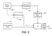
- the output X ( ⁇ ) 300 of the sensor can be characterized as a combination of the sound source signal S ( ⁇ ) 302 produced by the audio sensor in response to sound emanating from the sound source as modified by the sensor response which includes a delay sub-component e -j ⁇ r 304 and a magnitude sub-component ⁇ ( ⁇ ) 306, a reverberation noise signal H ( ⁇ ) 308 produced by the audio sensor in response to the reverberation of the sound emanating from the sound source, and the environmental noise signal N ( ⁇ ) 310 produced by the audio sensor in response to environmental noise.
- the ⁇ that maximizes the above correlation is the estimated time delay between the two signals.
- Eq. (6) is also known as the steered response power (SRP) of the microphone array.
- SRP-PHAT This algorithm is called SRP-PHAT. Note SRP-PHAT is very efficient to compute, because the number of weighting and summations drops from P 2 in Eq. (7) to P .
- a more theoretically-sound weighting function is the maximum likelihood (ML) formulation, assuming high signal to noise ratio and no reverberation.
- Eq. (10) can be inserted into Eq. (7) to obtain a ML based algorithm.
- This algorithm is known to be robust to environmental noise, but its performance in real-world applications is relatively poor, because reverberation is not modeled during its derivation. An improved version considers the reverberation explicitly.
- Eq. (11) is then plugged into Eq. (10) (replacing N i ( ⁇ ) with N i c ⁇ to obtain the new weighting function.
- the present multi-sensor SSL involves selecting a sound source location that results in a time of propagation from the sound source to the audio sensors, which maximizes a likelihood of producing the inputted audio sensor output signals.
- One embodiment of a technique to implement this task is outlined in Figs. 4A-B .
- the technique is based on a characterization of the signal output from each audio sensor in the microphone array as a combination of signal components. These components include a sound source signal produced by the audio sensor in response to sound emanating from the sound source, as modified by a sensor response which comprises a delay sub-component and a magnitude sub-component.
- a reverberation noise signal produced by the audio sensor in response to a reverberation of the sound emanating from the sound source.
- the technique begins by measuring or estimating the sensor response magnitude sub-component, reverberation noise and environmental noise for each of the audio sensor output signals (400).
- the environmental noise this can be estimated based on silence periods of the acoustical signals. These are portions of the sensor signal that do not contain signal components of the sound source and reverberation noise.
- the reverberation noise this can be estimated as a prescribed proportion of the sensor output signal less the estimated environmental noise signal.
- the prescribed proportion is generally a percentage of the sensor output signal that is attributable to the reverberation of a sound typically experienced in the environment, and will depend on the circumstances of the environment. For example, the prescribed proportion is lower when the environment is sound absorbing and is lower when the sound source is anticipated to be located near the microphone array.
- a set of candidate sound source locations are established (402).
- Each of the candidate location represents a possible location of the sound source.
- This last task can be done in a variety of ways.
- the locations can be chosen in a regular pattern surrounding the microphone array. In one implementation this is accomplished by choosing points at regular intervals around each of a set of concentric circles of increasing radii lying in a plane defined by the audio sensors of the array.
- Another example of how the candidate locations can be established involves choosing locations in a region of the environment surrounding the array where it is known that the sound source is generally located. For instance, conventional methods for finding the direction of a sound source from a microphone array can be employed. Once a direction is determined, the candidate locations are chosen in the region of the environment in that general direction.
- the technique continues with the selection of a previously unselected candidate sound source location (404).
- the sensor response delay sub-component that would be exhibited if the selected candidate location was the actual sound source location is then estimated for each of the audio sensor output signals (406).
- the delay sub-component of an audio sensor is dependent on the time of propagation from the sound source to sensor, as will be described in greater detail later. Given this, and assuming a prior knowledge of the location of each audio sensor, the time of propagation of sound from each candidate sound source location to each of the audio sensors can be computed. It is this time of propagation that is used to estimate the sensor response delay sub-component.
- the sound source signal that would be produced by each audio sensor in response to sound emanating from a sound source at the selected candidate location is estimated (408) based on the previously described characterization of the audio sensor output signals.
- These measured and estimated components are then used to compute an estimated sensor output signal of each audio sensor for the selected candidate sound source location (410). This is again done using the foregoing signal characterization. It is next determined if there are any remaining unselected candidate sound source locations (412). If so, actions 404 through 412 are repeated until all the candidate locations have been considered and an estimated audio sensor output signal has been computed for each sensor and each candidate sound source location.
- the estimated audio sensor output signals has been computed, it is next .ascertained which candidate sound source location produces a set of estimated sensor output signals from the audio sensors that are closest to the actual sensor output signals of the sensors (414). The location that produces the closest set is designated as the aforementioned selected sound source location that maximizes the likelihood of producing the inputted audio sensor output signals (416).
- X ( ⁇ ) represents the received signals and is known.
- G ( ⁇ ) can be estimated or hypothesized during the SSL process, which will be detailed later.
- the reverberation term S ( ⁇ ) H ( ⁇ ) is unknown, and will be treated as another type of noise.
- N c ⁇ S ⁇ ⁇ H ⁇ + N ⁇
- p N c ⁇ ⁇ ⁇ exp - 1 2 ⁇ N c ⁇ H ⁇ Q - 1 ⁇ ⁇ N c ⁇
- ⁇ is a constant
- superscript H represents the Hermitian transpose
- Q ( ⁇ ) is the covariance matrix, which can be estimated by:
- Eq. (19) assumes the reverberation energy is a portion of the difference between the total received signal energy and the environmental noise energy. The same assumption was used in Eq. (11). Note again that Eq. (19) is an approximation, because normally the reverberation signals received at different sensors are correlated, and the matrix should have non-zero off-diagonal elements. Unfortunately, it is generally very difficult to estimate the actual reverberation signals or these off-diagonal elements in practice. In the following analysis, Q ( ⁇ ) will be used to represent the noise covariance matrix, hence the derivation is applicable even when it does contain non-zero off-diagonal elements.
- the likelihood of the received signals can be written as: p X
- S , G , Q ⁇ ⁇ p X ⁇
- the present SSL technique maximizes the above likelihood, given the observations X ( ⁇ ), sensor response matrix G ( ⁇ ) and noise covariance matrix Q ( ⁇ ).
- the sensor response matrix G ( ⁇ ) requires information about where the sound source comes from, hence the optimization is usually solved through hypothesis testing. That is, hypotheses are made about the sound source location, which gives G ( ⁇ ). The likelihood is then measured. The hypothesis that results in the highest likelihood is determined to be the output of the SSL algorithm.
- each J ( ⁇ ) can be minimized separately by varying the unknown variable S ( ⁇ ).
- Q -1 ( ⁇ ) is a Hermitian symmetric matrix
- Q -1 ( ⁇ ) Q - H ( ⁇ )
- J 2 ⁇ ⁇ ⁇ S ⁇ 2 G H ⁇ ⁇ Q - 1 ⁇ ⁇ G ⁇ - 1 ⁇ d ⁇ .
- the denominator [ G H ( ⁇ ) Q -1 ( ⁇ ) G ( ⁇ )] -1 can be shown as the residue noise power after MVDR beamforming.
- this ML-based SSL is similar to having multiple MVDR beamformers perform beamforming along multiple hypothesis directions and picking the output direction as the one which results in the highest signal to noise ratio.
- the present technique differs from the ML algorithm in Eq. (10) in the additional frequency-dependent weighting. It also has a more rigorous derivation and is a true ML technique for multiple sensors pairs.
- the present technique involves ascertaining which candidate sound source location produces a set of estimated sensor output signals from the audio sensors that are closest to the actual sensor output signals.
- Eqs. (34) and (37) represent two of the ways the closest set can be found in the context of a maximization technique.
- Figs. 5A-B shows one embodiment for implementing this maximization technique.
- the technique begins with inputting the audio sensor output signal from each of the sensors in the microphone array (500) and computing the frequency transform of each of the signals (502). Any appropriate frequency transform can be employed for this purpose. In addition, the frequency transform can be limited to just those frequencies or frequency ranges that are known to be exhibited by the sound source. In this way, the processing cost is reduced as only frequencies of interest are handled.
- a set of candidate sound source locations are established (504).
- one of the previously unselected frequency transformed audio sensor output signals X ⁇ ( ⁇ ) is selected (506).
- 2 ⁇ of the selected output signal X i ( ⁇ ) is estimated for each frequency of interest ⁇ (508).
- 2 is computed for the selected signal X i ( ⁇ ) for each frequency of interest ⁇ (510).
- the magnitude sub-component ⁇ i ( ⁇ ) of the response of the audio sensor associated with the selected signal X i ( ⁇ ) is measured for each frequency of interest ⁇ (512). It is noted that the optional nature of this action is indicated by the dashed line box in Fig. 5A . It is then determined if there are any remaining unselected audio sensor output signals X i ( ⁇ ) (514). If so, actions (506) through (514) are repeated.
- a previously unselected one of the candidate sound source locations is selected (516).
- the time of propagation ⁇ i from the selected candidate sound source location to the audio sensor associated with the selected output signal is then computed (518). It is then determined if the magnitude sub-component ⁇ i ( ⁇ ) was measured (520). If so, Eq. (34) is computed (522), and if not, Eq. (37) is computed (524). In either case, the resulting value for J 2 is recorded (526). It is then determined if there are any remaining candidate sound source locations that have not been selected (528). If there are remaining locations, actions (516) through (528) are repeated. If there are no locations left to select, then a value of J 2 has been computed at each candidate sound source location. Given this, the candidate sound source location that produces the maximum value of J 2 is designated as the estimated sound source location (530).
- the signals output by the audio sensors of the microphone array will be digital signals.
- the frequencies of interest with regard to the audio sensor output signals, the expected environmental noise power spectrum of each signal, the audio sensor output signal power spectrum of each signal and the magnitude component of the audio sensor response associated with each signal are frequency bins as defined by the digital signal. Accordingly, Eqs. (34) and (37) are computed as a summation across all the frequency bins of interest rather than as an integral.
Description
- Sound source localization (SSL) using microphone arrays is employed in many important applications such as human-computer interaction and intelligent rooms. A large number of SSL algorithms have been proposed, with varying degrees of accuracy and computational complexity. For example, in broadband acoustic source localization applications such as teleconferencing, a number of SSL techniques are popular. These include steered-beamformer (SB), high-resolution spectral estimation, time delay of arrival (TDOA), and learning based techniques.
- In regard to the TDOA approach, most existing algorithms take each pair of audio sensors in the microphone array and compute their cross-correlation function. In order to compensate for reverberation and noise in the environment a weighting function is often employed in front of the correlation. A number of weighting functions have been tried. Among them is the maximum likelihood (ML) weighting function.
- However, these existing TDOA algorithms are designed to find the optimal weight for pairs of audio sensors. When more than one pair of sensors exists in the microphone array an assumption is made that pairs of sensors are independent and their likelihood can be multiplied together. This approach is questionable as the sensor pairs are typically not truly independent. Thus, these existing TDOA algorithms do not represent true ML algorithms for microphone arrays having more than one pair of audio sensors.
-
US 6 970 796 B2 relates to a system and process for improving the precision of localization estimates generated by use of a microphone array by providing cluster-based statistical post-processing of initial localization measurements or estimates. The post-processing system and method applies a statistical real-time clustering process to the initial localization estimates, and then uses this real-time clustering to generate new localization estimates having improved precision and reliability relative to the initial localization estimates. The system and method provides improved precision and reliability where initial object localization estimates are gathered in environments which include noise, reflections, reverberations, or other interference. The post-processing system takes an input of conventional localization estimates, with each localization estimate comprising: first positional data; second estimated positional reliability; and third, a data time stamp. All localization measurement older than a predetermined time are discarded. The post-processing then continues with a multi-stage process including: 1) "clustering" the initial localization estimates within the predetermined life-time in spatially spread overlapping sections; 2) identifying "potential objects" within the clusters; 3) estimating the position and standard deviation of the potential objects based on the clustering; and 4) eliminating likely duplicate objects. The post-processing may further continue by computing a confidence level for the position estimate for each object. A life-time computation module computes optimized localization estimate lifetimes based on computed object motions. Approximate object motions are computed as a function of time. Given these object motions, an appropriate life-time for localization estimates for each object are determined. The factors affecting the computed confidence levels are the number of measurements, the standard deviation and the latest time stamp among these measurements. The final confidence level is calculated as the product of the sub-confidence factors. -
US 7 035 764 B2 relates to systems and processes for tracking an object state over time using sensor fusion techniques, and more particularly to a system and process having a two-level closed-loop, particle filter sensor fusion architecture. A reliable speaker tracking technique involves the fusion of high-performance audio-based sound source localization (SSL) with vision-based tracking techniques to establish and track the location of a speaker. The fuser generates a set of hypotheses (also called particles) to cover the possible state space. All the hypotheses are then sent to the verifiers which compute the likelihood of the hypotheses and report back to the fuser. The fuser then uses weighted hypotheses to estimate the distribution of the object state. The tracking system and process employs a plurality of logical sensors where one of the logical sensors is a vision-based object contour sensor that tracks the location of human heads within an image of a scene where the speaker is present using head shape as the cue. Another logical sensor is a vision-based color sensor which can track the location of human heads within an image using head color as a visual cue. Another logical sensor is an audio-based sound source location sensor that tracks the location of the source of human speech using a microphone array. The verification procedure involves each logical sensor estimating the likelihood of each particle provided by the fuser module. Thus, each logical sensor has two parts - namely an object state tracker for generating the object state estimates and an object state verifier for verifying the particles generated by the fuser module. The likelihood models used by the tracker and verifier can differ. Once the likelihood estimates are generated for each particle by each of the logical sensors and provided to the fuser module, the fuser computes a combined likelihood model for the particle, the fuser computes the weight in the current iteration. Particles and particle weights are then used by the fuser module to compute a final estimate of the object state for the current tracking iteration. The system state is a Markov process and the observations are conditionally independent. The system cares the most about the horizontal location of the speaker. This simplifies the SSL tracker device considerably as all that is needed is to have two microphones to estimate xt c . Assuming the signal and noise are uncorrelated, the time delay can be estimated by finding the maximum cross-correlation between the signals received by the two microphones. For the SSL verifier, it is possible to use a more accurate likelihood model by keeping the whole correlation curve. Given a hypothesis, its likelihood defined as the ratio between its own height and the highest peak in the correlation curve. - The present multi-sensor sound source localization (SSL) technique provides a true maximum likelihood (ML) treatment for microphone arrays having more than one pair of audio sensors. This technique estimates the location of a sound source using signals output by each audio sensor of a microphone array placed so as to pick up sound emanating from the source in an environment exhibiting reverberation and environmental noise. Generally, this is accomplished by selecting a sound source location that results in a time of propagation from the sound source to the audio sensors of the array, which maximizes a likelihood of simultaneously producing audio sensor output signals inputted from all the sensors in the array. The likelihood includes a unique term that estimates an unknown audio sensor response to the source signal for each of the sensors.
- It is noted that while the foregoing limitations in existing SSL techniques described in the Background section can be resolved by a particular implementation of an multi-sensor SSL technique according to the present invention, this is in no way limited to implementations that just solve any or all of the noted disadvantages. Rather, the present technique has a much wider application as will become evident from the descriptions to follow.
- It should also be noted that this Summary is provided to introduce a selection of concepts, in a simplified form, that are further described below in the Detailed Description. This Summary is not intended to identify key features or essential features of the claimed subject matter, nor is it intended to be used as an aid in determining the scope of the claimed subject matter. In addition to the just described benefits, other advantages of the present invention will become apparent from the detailed description which follows hereinafter when taken in conjunction with the drawing figures which accompany it.
- The specific features, aspects, and advantages of the present invention will become better understood with regard to the following description, appended claims, and accompanying drawings where:
-
FIG. 1 is a diagram depicting a general purpose computing device constituting an exemplary system for implementing the present invention. -
FIG. 2 is a flow diagram generally outlining a technique for estimating the location of a sound source using signals output by a microphone array. -
FIG. 3 is a block diagram illustrating a characterization of the signal components making up the output of an audio sensor of the microphone array. -
FIGS. 4A-B are a continuing flow diagram generally outlining an embodiment of a technique for implementing the multi-sensor sound source localization ofFig. 2 . -
FIGS. 5A-B are a continuing flow diagram generally outlining a mathematical implementation of the multi-sensor sound source localization ofFigs. 4A-B . - In the following description of embodiments of the present invention reference is made to the accompanying drawings which form a part hereof, and in which are shown, by way of illustration, specific embodiments in which the invention may be practiced. It is understood that other embodiments may be utilized and structural changes may be made without departing from the scope of the present invention.
- Before providing a description of embodiments of the present multi-sensor SSL technique, a brief, general description of a suitable computing environment in which portions thereof may be implemented will be described. The present multi-sensor SSL technique is operational with numerous general purpose or special purpose computing system environments or configurations. Examples of well known computing systems, environments, and/or configurations that may be suitable include, but are not limited to, personal computers, server computers, hand-held or laptop devices, multiprocessor systems, microprocessor-based systems, set top boxes, programmable consumer electronics, network PCs, minicomputers, mainframe computers, distributed computing environments that include any of the above systems or devices, and the like.
-
Fig. 1 illustrates an example of a suitable computing system environment. The computing system environment is only one example of a suitable computing environment and is not intended to suggest any limitation as to the scope of use or functionality of the present multi-sensor SSL technique. Neither should the computing environment be interpreted as having any dependency or requirement relating to any one or combination of components illustrated in the exemplary operating environment. With reference toFig. 1 , an exemplary system for implementing the present multi-sensor SSL technique includes a computing device, such ascomputing device 100. In its most basic configuration,computing device 100 typically includes at least oneprocessing unit 102 andmemory 104. Depending on the exact configuration and type of computing device,memory 104 may be volatile (such as RAM), non-volatile (such as ROM, flash memory, etc.) or some combination of the two. This most basic configuration is illustrated inFig. 1 by dashedline 106. Additionally,device 100 may also have additional features/functionality. For example,device 100 may also include additional storage (removable and/or non-removable) including, but not limited to, magnetic or optical disks or tape. Such additional storage is illustrated inFig. 1 byremovable storage 108 andnon-removable storage 110. Computer storage media includes volatile and nonvolatile, removable and non-removable media implemented in any method or technology for storage of information such as computer readable instructions, data structures, program modules or other data.Memory 104,removable storage 108 andnon-removable storage 110 are all examples of computer storage media. Computer storage media includes, but is not limited to, RAM, ROM, EEPROM, flash memory or other memory technology, CD-ROM, digital versatile disks (DVD) or other optical storage, magnetic cassettes, magnetic tape, magnetic disk storage or other magnetic storage devices, or any other medium which can be used to store the desired information and which can accessed bydevice 100. Any such computer storage media may be part ofdevice 100. -
Device 100 may also contain communications connection(s) 112 that allow the device to communicate with other devices. Communications connection(s) 112 is an example of communication media. Communication media typically embodies computer readable instructions, data structures, program modules or other data in a modulated data signal such as a carrier wave or other transport mechanism and includes any information delivery media. The term "modulated data signal" means a signal that has one or more of its characteristics set or changed in such a manner as to encode information in the signal. By way of example, and not limitation, communication media includes wired media such as a wired network or direct-wired connection, and wireless media such as acoustic, RF, infrared and other wireless media. The term computer readable media as used herein includes both storage media and communication media. -
Device 100 may also have input device(s) 114 such as keyboard, mouse, pen, voice input device, touch input device, camera, etc. Output device(s) 116 such as a display, speakers, printer, etc. may also be included. All these devices are well know in the art and need not be discussed at length here. - Of particular note is that
device 100 includes amicrophone array 118 having multiple audio sensors, each of which is capable of capturing sound and producing an output signal representative of the captured sound. The audio sensor output signals are input into thedevice 100 via an appropriate interface (not shown). However, it is noted that audio data can also be input into thedevice 100 from any computer-readable media as well, without requiring the use of a microphone array. - The present multi-sensor SSL technique may be described in the general context of computer-executable instructions, such as program modules, being executed by a computing device. Generally, program modules include routines, programs, objects, components, data structures, etc. that perform particular tasks or implement particular abstract data types. The present multi-sensor SSL technique may also be practiced in distributed computing environments where tasks are performed by remote processing devices that are linked through a communications network. In a distributed computing environment, program modules may be located in both local and remote computer storage media including memory storage devices.
- The exemplary operating environment having now been discussed, the remaining parts of this description section will be devoted to a description of the program modules embodying the present multi-sensor SSL technique.
- The present multi-sensor sound source localization (SSL) technique estimates the location of a sound source using signals output by a microphone array having multiple audio sensors placed so as to pick up sound emanating from the source in an environment exhibiting reverberation and environmental noise. Referring to
Fig. 2 , in general the present technique involves first inputting the output signal from each audio sensor in the array (200). Then a sound source location is selected that would result in a time of propagation from the sound source to the audio sensors, which maximizes the likelihood of simultaneously producing all the inputted audio sensor output signals (202). The selected location is then designated as the estimated sound source location (204). - The present technique and in particular how the aforementioned sound source location is selected will be described in more detail in the sections to follow, starting with a mathematical description of the existing approaches.
- Consider an array of P audio sensors. Given a source signal s(t), the signals received at these sensors can be modeled as:

where i = 1,···, P is the index of the sensors; τ i is the time of propagation from the source location to the ith sensor location; α i is an audio sensor response factor that includes the propagation energy decay of the signal, the gain of the corresponding sensor, the directionality of the source and the sensor, and other factors; ni (t) is the noise sensed by the i th sensor; h¡(t)Ⓧs(t) represents the convolution between the environmental response function and the source signal, often referred as the reverberation. It is usually more efficient to work in the frequency domain, where the above model can be rewritten as:
- Thus, as shown in
Fig. 3 , for each sensor in the array, the output X(ω) 300 of the sensor can be characterized as a combination of the sound source signal S(ω) 302 produced by the audio sensor in response to sound emanating from the sound source as modified by the sensor response which includes adelay sub-component e -jωr 304 and a magnitude sub-component α(ω) 306, a reverberation noise signal H(ω) 308 produced by the audio sensor in response to the reverberation of the sound emanating from the sound source, and the environmental noise signal N(ω) 310 produced by the audio sensor in response to environmental noise. - The most straightforward SSL technique is to take each pair of the sensors and compute their cross-correlation function. For instance, the correlation between the signals received at sensor i and k is:

- The τ that maximizes the above correlation is the estimated time delay between the two signals. In practice, the above cross-correlation function can be computed more efficiently in the frequency domain as:

where * represents complex conjugate. If Eq. (2) is plugged into Eq. (4), the reverberation term is ignored and the noise and source signal are assumed to be independent, the τ that maximizes the above correlation is τ i - τ k , which is the actual delay between the two sensors. When more than two sensors are considered, the sum over all possible pairs of sensors is taken to produce:
- The common practice is to maximize the above correlation through hypothesis testing, where s is the hypothesized source location, which determines the τ i 's on the right. Eq. (6) is also known as the steered response power (SRP) of the microphone array.
- To address the reverberation and noise that may affect the SSL accuracy, it has been found that adding a weighting function in front of the correlation can greatly help. Eq. (5) is thus rewritten as:

- A number of weighting functions have been tried. Among them, the heuristic-based PHAT weighting defined as:

has been found to perform very well under realistic acoustical conditions. Inserting Eq. (8) into Eq. (7), one gets:
- This algorithm is called SRP-PHAT. Note SRP-PHAT is very efficient to compute, because the number of weighting and summations drops from P 2 in Eq. (7) to P.
- A more theoretically-sound weighting function is the maximum likelihood (ML) formulation, assuming high signal to noise ratio and no reverberation. The weighting function of a sensor pair is defined as:

- Eq. (10) can be inserted into Eq. (7) to obtain a ML based algorithm. This algorithm is known to be robust to environmental noise, but its performance in real-world applications is relatively poor, because reverberation is not modeled during its derivation. An improved version considers the reverberation explicitly. The reverberation is treated as another type of noise:

where


whose computational efficiency is close to SRP-PHAT. - Note that algorithms derived from Eq. (10) are not true ML algorithms. This is because the optimal weight in Eq. (10) is derived for only two sensors. When more than 2 sensors are used, the adoption of Eq. (7) assumes that pairs of sensors are independent and their likelihood can be multiplied together, which is questionable. The present multi-sensor SSL technique is a true ML algorithm for the case of multiple audio sensors, as will be described next.
- As stated previously, the present multi-sensor SSL involves selecting a sound source location that results in a time of propagation from the sound source to the audio sensors, which maximizes a likelihood of producing the inputted audio sensor output signals. One embodiment of a technique to implement this task is outlined in
Figs. 4A-B . The technique is based on a characterization of the signal output from each audio sensor in the microphone array as a combination of signal components. These components include a sound source signal produced by the audio sensor in response to sound emanating from the sound source, as modified by a sensor response which comprises a delay sub-component and a magnitude sub-component. In addition, there is a reverberation noise signal produced by the audio sensor in response to a reverberation of the sound emanating from the sound source. Further, there is an environmental noise signal produced by the audio sensor in response to environmental noise. - Given the foregoing characterization, the technique begins by measuring or estimating the sensor response magnitude sub-component, reverberation noise and environmental noise for each of the audio sensor output signals (400). In regard to the environmental noise, this can be estimated based on silence periods of the acoustical signals. These are portions of the sensor signal that do not contain signal components of the sound source and reverberation noise. In regard to the reverberation noise, this can be estimated as a prescribed proportion of the sensor output signal less the estimated environmental noise signal. The prescribed proportion is generally a percentage of the sensor output signal that is attributable to the reverberation of a sound typically experienced in the environment, and will depend on the circumstances of the environment. For example, the prescribed proportion is lower when the environment is sound absorbing and is lower when the sound source is anticipated to be located near the microphone array.
- Next, a set of candidate sound source locations are established (402). Each of the candidate location represents a possible location of the sound source. This last task can be done in a variety of ways. For example, the locations can be chosen in a regular pattern surrounding the microphone array. In one implementation this is accomplished by choosing points at regular intervals around each of a set of concentric circles of increasing radii lying in a plane defined by the audio sensors of the array. Another example of how the candidate locations can be established involves choosing locations in a region of the environment surrounding the array where it is known that the sound source is generally located. For instance, conventional methods for finding the direction of a sound source from a microphone array can be employed. Once a direction is determined, the candidate locations are chosen in the region of the environment in that general direction.
- The technique continues with the selection of a previously unselected candidate sound source location (404). The sensor response delay sub-component that would be exhibited if the selected candidate location was the actual sound source location is then estimated for each of the audio sensor output signals (406). It is noted that the delay sub-component of an audio sensor is dependent on the time of propagation from the sound source to sensor, as will be described in greater detail later. Given this, and assuming a prior knowledge of the location of each audio sensor, the time of propagation of sound from each candidate sound source location to each of the audio sensors can be computed. It is this time of propagation that is used to estimate the sensor response delay sub-component.
- Given the measurements or estimates for the sensor response subcomponents, reverberation noise and environmental noise associated with each of the audio sensor output signals, the sound source signal that would be produced by each audio sensor in response to sound emanating from a sound source at the selected candidate location (if unmodified by the response of the sensor) is estimated (408) based on the previously described characterization of the audio sensor output signals. These measured and estimated components are then used to compute an estimated sensor output signal of each audio sensor for the selected candidate sound source location (410). This is again done using the foregoing signal characterization. It is next determined if there are any remaining unselected candidate sound source locations (412). If so,
actions 404 through 412 are repeated until all the candidate locations have been considered and an estimated audio sensor output signal has been computed for each sensor and each candidate sound source location. - Once the estimated audio sensor output signals has been computed, it is next .ascertained which candidate sound source location produces a set of estimated sensor output signals from the audio sensors that are closest to the actual sensor output signals of the sensors (414). The location that produces the closest set is designated as the aforementioned selected sound source location that maximizes the likelihood of producing the inputted audio sensor output signals (416).
- In mathematical terms the foregoing technique can be described as follows. First, Eq. (2) is rewritten into a vector form:

where - X(ω)=
- [X 1(ω),···,X, P (ω)] T ,
- G(ω) =
- [α 1(ω)e -jωτ
1 ,···αP (ω)e-jωτP ] T, - H(ω) =
- [H 1(ω),···,HP (ω)] T ,
- N(ω)=
- [N 1(ω),···,NP (ω)] T.
- Among the variables, X(ω) represents the received signals and is known. G(ω) can be estimated or hypothesized during the SSL process, which will be detailed later. The reverberation term S(ω)H(ω) is unknown, and will be treated as another type of noise.
- To make the above model mathematically tractable, assume the combined total noise,

follows a zero-mean, independent between frequencies, joint Gaussian distribution, i.e.,
where ρ is a constant; superscript H represents the Hermitian transpose, and Q(ω) is the covariance matrix, which can be estimated by:
- Here it is assumed the noise and the reverberation are uncorrelated. The first term in Eq. (16) can be directly estimated from the aforementioned silence periods of the acoustical signals:

where k is the index of audio frames that are silent. Note that the background noises received at different sensors may be correlated, such as the ones generated by computer fans in the room. If it is believed the noises are independent at different sensors, the first term of Eq. (16) can be simplified further as a diagonal matrix:
- The second term in Eq. (16) is related to reverberation. It is generally unknown. As an approximation, assume it is a diagonal matrix:

with the i th diagonal element as:
where 0 < γ < 1 is an empirical noise parameter. It is noted that in tested embodiments of the present technique, γ was set to between about 0.1 and about 0.5 depending on the reverberation characteristics of the environment. It is also noted that Eq. (20) assumes the reverberation energy is a portion of the difference between the total received signal energy and the environmental noise energy. The same assumption was used in Eq. (11). Note again that Eq. (19) is an approximation, because normally the reverberation signals received at different sensors are correlated, and the matrix should have non-zero off-diagonal elements. Unfortunately, it is generally very difficult to estimate the actual reverberation signals or these off-diagonal elements in practice. In the following analysis, Q(ω) will be used to represent the noise covariance matrix, hence the derivation is applicable even when it does contain non-zero off-diagonal elements. - When the covariance matrix Q(ω) can be calculated or estimated from known signals, the likelihood of the received signals can be written as:

where
and
- The present SSL technique maximizes the above likelihood, given the observations X(ω), sensor response matrix G(ω) and noise covariance matrix Q(ω). Note the sensor response matrix G(ω) requires information about where the sound source comes from, hence the optimization is usually solved through hypothesis testing. That is, hypotheses are made about the sound source location, which gives G(ω). The likelihood is then measured. The hypothesis that results in the highest likelihood is determined to be the output of the SSL algorithm.
- Instead of maximizing the likelihood in Eq. (21), the following negative log-likelihood can be minimized:

- Since it is assumed the probabilities over the frequencies are independent to each other, each J(ω) can be minimized separately by varying the unknown variable S(ω). Given Q -1(ω) is a Hermitian symmetric matrix, Q -1(ω) = Q -H (ω), if the derivative of J(ω) is taken over S(ω), and set to zero, it produces:

Therefore,
Next, insert the above S(ω) to J(ω):
where

- Note that J 1(ω) is not related to the hypothesized locations during hypothesis testing. Therefore, the present ML based SSL technique just maximizes:

- Due to Eq. (26), J 2 can be rewritten as:

- The denominator [G H (ω)Q -1(ω)G(ω)]-1 can be shown as the residue noise power after MVDR beamforming. Hence this ML-based SSL is similar to having multiple MVDR beamformers perform beamforming along multiple hypothesis directions and picking the output direction as the one which results in the highest signal to noise ratio.
- Next, assume that the noises in the sensors are independent, thus Q(ω) is a diagonal matrix:

with the i th diagonal element as:
- Eq. (30) can thus be written as:

- The sensor response factor α i (ω) can be accurately measured in some applications. For applications where it is unknown, it can be assumed it is a positive real number and estimate it as follows:

where both sides represent the power of the signal received at sensor i without the combined noise (noise and reverberation). Therefore,
- Inserting Eq. (36) into Eq. (34) produces:

- It is noted that the present technique differs from the ML algorithm in Eq. (10) in the additional frequency-dependent weighting. It also has a more rigorous derivation and is a true ML technique for multiple sensors pairs.
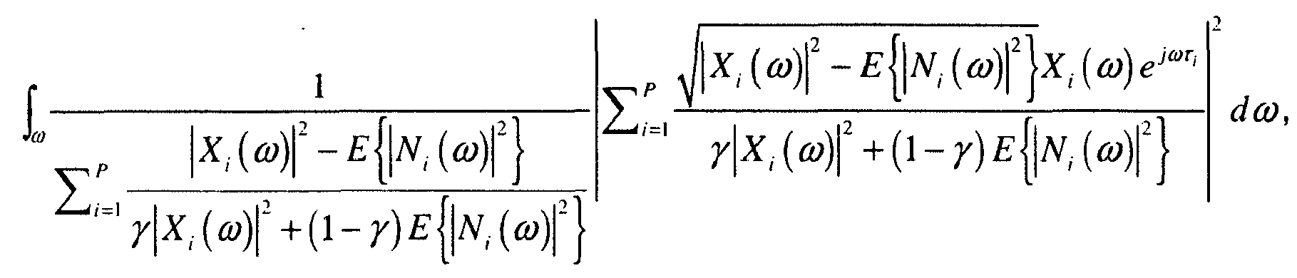
- As indicated previously, the present technique involves ascertaining which candidate sound source location produces a set of estimated sensor output signals from the audio sensors that are closest to the actual sensor output signals. Eqs. (34) and (37) represent two of the ways the closest set can be found in the context of a maximization technique.
Figs. 5A-B shows one embodiment for implementing this maximization technique. - The technique begins with inputting the audio sensor output signal from each of the sensors in the microphone array (500) and computing the frequency transform of each of the signals (502). Any appropriate frequency transform can be employed for this purpose. In addition, the frequency transform can be limited to just those frequencies or frequency ranges that are known to be exhibited by the sound source. In this way, the processing cost is reduced as only frequencies of interest are handled. As in the previously described general procedure for estimating the SSL, a set of candidate sound source locations are established (504). Next, one of the previously unselected frequency transformed audio sensor output signals X¡ (ω) is selected (506). The expected environmental noise power spectrum E{|Ni(ω)|2} of the selected output signal Xi (ω) is estimated for each frequency of interest ω (508). In addition, the audio sensor output signal power spectrum |Xi(ω)|2 is computed for the selected signal Xi (ω) for each frequency of interest ω (510). Optionally, the magnitude sub-component α i (ω) of the response of the audio sensor associated with the selected signal Xi (ω) is measured for each frequency of interest ω (512). It is noted that the optional nature of this action is indicated by the dashed line box in
Fig. 5A . It is then determined if there are any remaining unselected audio sensor output signals Xi (ω) (514). If so, actions (506) through (514) are repeated. - Referring now to
Fig. 5B , if it is determined that there are no remaining unselected audio sensor output signals, a previously unselected one of the candidate sound source locations is selected (516). The time of propagation τ i from the selected candidate sound source location to the audio sensor associated with the selected output signal is then computed (518). It is then determined if the magnitude sub-component α i (ω) was measured (520). If so, Eq. (34) is computed (522), and if not, Eq. (37) is computed (524). In either case, the resulting value for J 2 is recorded (526). It is then determined if there are any remaining candidate sound source locations that have not been selected (528). If there are remaining locations, actions (516) through (528) are repeated. If there are no locations left to select, then a value of J 2 has been computed at each candidate sound source location. Given this, the candidate sound source location that produces the maximum value of J 2 is designated as the estimated sound source location (530). - It is noted that in many practical applications of the foregoing technique, the signals output by the audio sensors of the microphone array will be digital signals. In that case, the frequencies of interest with regard to the audio sensor output signals, the expected environmental noise power spectrum of each signal, the audio sensor output signal power spectrum of each signal and the magnitude component of the audio sensor response associated with each signal are frequency bins as defined by the digital signal. Accordingly, Eqs. (34) and (37) are computed as a summation across all the frequency bins of interest rather than as an integral.
- It should also be noted that any or all of the aforementioned embodiments throughout the description may be used in any combination desired to form additional hybrid embodiments. Although the subject matter has been described in language specific to structural features and/or methodological acts, it is to be understood that the subject matter defined in the appended claims is not necessarily limited to the specific features or acts described above. Rather, the specific features and acts described above are disclosed as example forms of implementing the claims.
-
- Item 1: A computer-implemented process for estimating the location of a sound source using signals output by a microphone array having plural audio sensors placed so as to pick up sound emanating from the source in an environment exhibiting reverberation and environmental noise, comprising using a computer to perform the following process actions:
- inputting the signal output by each of the audio sensors (200);
- selecting as the location of the sound source, a location resulting in a time of propagation from the selected location to each audio sensor that maximizes a likelihood of simultaneously producing the signal output from all the sensors in the array (202) wherein the likelihood comprises a term that estimates an unknown audio sensor response to the source signal for each of the sensors in the array; and
- designating the selected location as the estimated sound source location (204).
- Item 2: The process of
embodiment 1, wherein the process action of selecting as the location of the sound source, a location resulting in a time of propagation from the selected location to each audio sensor that maximizes a likelihood of producing the signal output of each sensor, comprises the actions of:- characterizing each sensor output signal as a combination of signal components comprising,
a sound source signal produced by the audio sensor in response to sound emanating from the sound source as modified by a sensor response which comprises a delay sub-component and a magnitude sub-component,
a reverberation noise signal produced by the audio sensor in response to a reverberation of the sound emanating from the sound source, and
an environmental noise signal produced by the audio sensor in response to environmental noise; - measuring or estimating the sensor response magnitude sub-component, reverberation noise signal and environmental noise signal associated with each audio sensor;
- estimating the sensor response delay sub-component for each of a prescribed set of candidate sound source locations for each of the audio sensors, wherein each candidate sound source location represents a possible location of the sound source;
- computing an estimated sound source signal as it would be produced by each audio sensor in response to sound emanating from the sound source if unmodified by the sensor response of that sensor using the measured or estimated sensor response magnitude sub-component, reverberation noise signal, environmental noise signal, and sensor response delay sub-component associated with each audio sensor for each candidate sound source location;
- computing an estimated sensor output signal for each audio sensor using the measured or estimated sound source signal, sensor response magnitude sub-component, reverberation noise signal, environmental noise signal, and sensor response delay sub-component associated with each audio sensor for each candidate sound source location;
- comparing the estimated sensor output signal for each audio sensor to the corresponding actual sensor output signals and determining which candidate sound source location produces a set of estimated sensor output signals that are the closest to the actual sensor output signals for the audio sensors as a whole; and
- designating the candidate sound source location associated with the closest set of estimated sensor output signals as the selected sound source location.
- characterizing each sensor output signal as a combination of signal components comprising,
- Item 3: The process of
embodiment 2, wherein the process action of measuring or estimating the sensor response magnitude sub-component, reverberation noise signal and environmental noise signal associated with each audio sensor, comprises the actions of:- measuring the sensor output signal; and
- estimating the environmental noise signal based on portions of the measured sensor signal that do not contain signal components comprising the sound source signal and the reverberation noise signal.
- Item 4: The process of embodiment 3, wherein the process action of measuring or estimating the sensor response magnitude sub-component, reverberation noise signal and environmental noise signal associated with each audio sensor, comprises an action of estimating the reverberation noise signal as a prescribed proportion of the measured sensor output signal less the estimated environmental noise signal.
- Item 5: The process of embodiment 4, wherein the process action of estimating the reverberation noise signal as a prescribed proportion of the measured sensor output signal less the estimated environmental noise signal, comprises an action of establishing, prior to estimating the location of a sound source, the prescribed proportion as a percentage of reverberation of a sound typically experienced in the environment, such that the prescribed proportion is lower when the environment is sound absorbing.
- Item 6: The process of embodiment 4, wherein the process action of estimating the reverberation noise signal as a prescribed proportion of the measured sensor output signal less the estimated environmental noise signal, comprises an action of establishing, prior to estimating the location of a sound source, the prescribed proportion as a percentage of reverberation of a sound in the environment, such that the prescribed proportion is set lower the closer the sound source is anticipated to be located to the microphone array.
- Item 7: The process of
embodiment 2, wherein the sensor response delay sub-component of an audio sensor is dependent on the time of propagation of sound emanating from the sound source to the audio sensor, and wherein the process action of estimating the sensor response delay sub-component for each of the prescribed set of candidate sound source locations for each of the audio sensors, comprises the actions of:- establishing, prior to estimating the location of a sound source, the set of candidate sound source locations;
- establishing, prior to estimating the location of a sound source, the location of each audio sensor in relation to the candidate sound source locations;
- for each audio sensor and each candidate sound source location, computing the time of propagation of sound emanating from the sound source to the audio sensor if the sound source were located at the candidate sound source location; and
- estimating the sensor response delay sub-component for each of the prescribed set of candidate sound source locations for each of the audio sensors using the computed time of propagation corresponding to each sensor and candidate location.
- Item 8: The process of embodiment 7, wherein the process action of establishing the set of candidate sound source locations, comprises an action of choosing locations in a regular pattern surrounding the microphone array.
- Item 9: The process of embodiment 8, wherein the process action of choosing locations in a regular pattern surrounding the microphone array, comprises the action of choosing points at regular intervals around each of a set of concentric circles of increasing radii lying in a plane defined by the plural audio sensors.
- Item 10: The process of embodiment 7, wherein the process action of establishing the set of candidate sound source locations, comprises an action of choosing locations in a region of the environment where it is known that the sound source is generally located.
- Item 11: The process of embodiment 7, wherein the process action of establishing the set of candidate sound source locations, comprises the actions of:
- establishing a general direction from the microphone array where the sound source is located;
- choosing locations in a region of the environment in said general direction.
- Item 12: The process of
embodiment 2, wherein the measured or estimated sound source signal, sensor response magnitude sub-component, reverberation noise signal, environmental noise signal, and sensor response delay sub-component associated with each audio sensor for each candidate sound source location, are measured or estimated for a particular point in time, and wherein the process action of computing the estimated sensor output signal for each audio sensor for each candidate sound source location comprises an action of computing the estimated sensor output signals for said point in time, such that the selected sound source location is deemed the location of the sound source at said point in time. - Item 13: The process of
embodiment 2, wherein the process action of determining which candidate sound source location produces a set of estimated sensor output signals that are the closest to the actual sensor output signals for the audio sensors as a whole, comprises the actions of:- for each candidate sound source location, computing the equation

- designating the candidate sound source location that maximizes the equation as the sound source location that produces a set of estimated sensor output signals that are the closest to the actual sensor output signals for the audio sensors as a whole.
- for each candidate sound source location, computing the equation
- Item 14: The process of
embodiment 2, wherein the process action of determining which candidate sound source location produces a set of estimated sensor output signals that are the closest to the actual sensor output signals for the audio sensors as a whole, comprises the actions of:- for each candidate sound source location, computing the equation
- designating the candidate sound source location that maximizes the equation as the sound source location that produces a set of estimated sensor output signals that are the closest to the actual sensor output signals for the audio sensors as a whole.
- for each candidate sound source location, computing the equation
- Item 15: A system for estimating the location of a sound source in an environment exhibiting reverberation and environmental noise, comprising:
- a microphone array having two or more audio sensors placed so as to pick up sound emanating from the sound source (118);
- a general purpose computing device (100);
- a computer program comprising program modules executable by the computing device, wherein the computing device is directed by the program modules of the computer program to,
input a signal output by each of the audio sensors (500);
compute a frequency transform of each audio sensor output signal (502);
establish a set of candidate sound source locations (504), each of which represents a possible location of the sound source;
for each candidate sound source location and each audio sensor, compute the time of propagation τ i from the candidate sound source location to the audio sensor (518), wherein i denotes which audio sensor;
for each frequency of interest of each frequency transformed audio sensor output signal,
estimate an expected environmental noise power spectrum E{|Ni {ω)|2} of the signal Xi (ω) (508), wherein ω denotes which frequency of interest, and
wherein the expected environmental noise power spectrum is the environmental noise power spectrum expected to be associated with the signal,
compute an audio sensor output signal power spectrum |Xi (ω)|2 for the signal Xi (ω) (510),
measure a magnitude sub-component of an audio sensor response αi (ω) of the sensor associated with the signal Xi (ω) (512);
for each candidate sound source location, compute the equation
P is the total number of audio sensors, * denotes a complex conjugate, and γ is a prescribed noise parameter (522); and
designate the candidate sound source location that maximizes the equation as the estimated sound source location (530).
- Item 16: The system of embodiment 15, wherein the signals output by the microphone array are digital signals, and wherein the frequency of interest of each of the audio sensor output signals, the expected environmental noise power spectrum of each signal, the audio sensor output signal power spectrum of each signal and the magnitude component of the audio sensor response associated with the signal are frequency bins as defined by the digital signal, and wherein the equation is computed as a summation across all the frequency bins rather than as an integral across the frequencies.
- Item 17: The system of embodiment 15, wherein the program module for computing a frequency transform of each audio sensor output signal, comprises an sub-module for limiting the frequency transform to just those frequencies known to be exhibited by the sound source.
- Item 18: The system of embodiment 15, wherein the prescribed noise parameter γ is a value ranging between about 0.1 and about 0.5.
- Item 19: A system for estimating the location of a sound source in an environment exhibiting reverberation and environmental noise, comprising:
- a microphone array having two or more audio sensors placed so as to pick up sound emanating from the sound source (118);
- a general purpose computing device (100);
- a computer program comprising program modules executable by the computing device, wherein the computing device is directed by the program modules of the computer program to,
input a signal output by each of the audio sensors (500);
compute a frequency transform of each audio sensor output signal (502);
establish a set of candidate sound source locations (504), each of which represents a possible location of the sound source;
for each candidate sound source location and each audio sensor, compute the time of propagation τ i from the candidate sound source location to the audio sensor (518), wherein i denotes which audio sensor;
for each frequency of interest of each frequency transformed audio sensor output signal,
estimate an expected environmental noise power spectrum E{|Ni (ω)|2} of the signal Xi (ω) (508), wherein ω denotes which frequency of interest, and wherein the expected environmental noise power spectrum is the environmental noise power spectrum expected to be associated with the signal,
compute an audio sensor output signal power spectrum |Xi (ω)|2 for the signal Xi (ω) (510),
for each candidate sound source location, compute the equation
where P is the total number of audio sensors and γ is a prescribed noise parameter (524); and
designate the candidate sound source location that maximizes the equation as the estimated sound source location (530).
- Item 20: The system of embodiment 19, wherein the signals output by the microphone array are digital signals, and wherein the frequency of interest of each of the audio sensor output signals, the expected environmental noise power spectrum of each signal and the audio sensor output signal power spectrum of each signal are frequency bins as defined by the digital signal, and wherein the equation is computed as a summation across all the frequency bins rather than as an integral across the frequencies.
Claims (15)
- A computer-implemented process for estimating the location of a sound source using signals output by a microphone array having plural audio sensors placed so as to pick up sound emanating from the source in an environment exhibiting reverberation and environmental noise, comprising using a computer to perform the following process actions:inputting the signal output by each of the audio sensors;measuring or estimating (400) an environmental noise signal associated with each audio sensor;establishing (402) a set of candidate sound source locations, wherein each candidate sound source location represents a possible location of the sound source;estimating (406) a sensor response delay sub-component for each sound source location of the set of candidate sound source locations for each of the audio sensors, wherein the sensor response delay sub-component of an audio sensor is dependent on the time of propagation of sound emanating from the sound source to the audio sensor, and wherein the process action of estimating the sensor response delay sub-component for each of the prescribed set of candidate sound source locations for each of the audio sensors, comprises the actions of:for each audio sensor and each candidate sound source location, computing the time of propagation of sound emanating from the sound source to the audio sensor if the sound source were located at the candidate sound source location; andestimating the sensor response delay sub-component for each of the prescribed set of candidate sound source locations for each of the audio sensors using the computed time of propagation corresponding to each sensor and candidate location;computing (410) an estimated sensor output signal for each audio sensor using the measured or estimated environmental noise signal associated with each audio sensor;computing (414) a likelihood of simultaneously producing the signal output from all the sensors in the array wherein the likelihood comprises a term that estimates an unknown audio sensor response to the source signal for each of the sensors in the array; anddesignating (416) the location that maximizes the likelihood as the estimated sound source location.
- The process of claim 1, further comprising:characterizing each sensor output signal as a combination of signal components comprising,
a sound source signal produced by the audio sensor in response to sound emanating from the sound source as modified by a sensor response which comprises a delay sub-component and a magnitude sub-component,
the reverberation noise signal produced by the audio sensor in response to a reverberation of the sound emanating from the sound source, and
an environmental noise signal produced by the audio sensor in response to environmental noise;measuring or estimating (400) the sensor response magnitude sub-component and reverberation noise signal associated with each audio sensor;computing (408) an estimated sound source signal as it would be produced by each audio sensor in response to sound emanating from the sound source if unmodified by the sensor response of that sensor using the measured or estimated sensor response magnitude sub-component, reverberation noise signal, environmental noise signal, and sensor response delay sub-component associated with each audio sensor for each candidate sound source location;wherein the computing (410) the estimated sensor output signal for each audio sensor further uses the measured or estimated sound source signal, sensor response magnitude sub-component, reverberation noise signal, and sensor response delay sub-component associated with each audio sensor for each candidate sound source location;comparing (414) the estimated sensor output signal for each audio sensor to the corresponding actual sensor output signals and determining which candidate sound source location produces a set of estimated sensor output signals that are the closest to the actual sensor output signals for the audio sensors as a whole; anddesignating the candidate sound source location associated with the closest set of estimated sensor output signals as the estimated sound source location. - The process of claim 2, wherein the process action of measuring or estimating the sensor response magnitude sub-component, reverberation noise signal and environmental noise signal associated with each audio sensor, comprises the actions of:measuring the sensor output signal; andestimating the environmental noise signal based on portions of the measured sensor signal that do not contain signal components comprising the sound source signal and the reverberation noise signal, and/orwherein the process action of measuring or estimating the sensor response magnitude sub-component, reverberation noise signal and environmental noise signal associated with each audio sensor, comprises an action of estimating the reverberation noise signal as a prescribed proportion of the measured sensor output signal less the estimated environmental noise signal and/orwherein the process action of estimating the reverberation noise signal as a prescribed proportion of the measured sensor output signal less the estimated environmental noise signal, comprises an action of establishing, prior to estimating the location of a sound source, the prescribed proportion as a percentage of reverberation of a sound typically experienced in the environment, such that the prescribed proportion is lower when the environment is sound absorbing.
- The process of claim 3, wherein the process action of estimating the reverberation noise signal as a prescribed proportion of the measured sensor output signal less the estimated environmental noise signal, comprises an action of establishing, prior to estimating the location of a sound source, the prescribed proportion as a percentage of reverberation of a sound in the environment, such that the prescribed proportion is set lower the closer the sound source is anticipated to be located to the microphone array.
- The process of claim 1, further comprising:establishing, prior to estimating the sensor response delay sub-component for each location of a sound source, the location of each audio sensor in relation to the candidate sound source locations.
- The process of claim 5, wherein the process action of establishing the set of candidate sound source locations, comprises an action of choosing locations in a regular pattern surrounding the microphone array, and/or
wherein the process action of choosing locations in a regular pattern surrounding the microphone array, comprises the action of choosing points at regular intervals around each of a set of concentric circles of increasing radii lying in a plane defined by the plural audio sensors. - The process of claim 5, wherein the process action of establishing the set of candidate sound source locations, comprises an action of choosing locations in a region of the environment where it is known that the sound source is generally located, or
wherein the process action of establishing the set of candidate sound source locations, comprises the actions of:establishing a general direction from the microphone array where the sound source is located;choosing locations in a region of the environment in said general direction. - The process of claim 2, wherein the measured or estimated sound source signal, sensor response magnitude sub-component, reverberation noise signal, environmental noise signal, and sensor response delay sub-component associated with each audio sensor for each candidate sound source location, are measured or estimated for a particular point in time, and wherein the process action of computing the estimated sensor output signal for each audio sensor for each candidate sound source location comprises an action of computing the estimated sensor output signals for said point in time, such that the selected sound source location is deemed the location of the sound source at said point in time.
- The process of claim 2, wherein the process action of determining which candidate sound source location produces a set of estimated sensor output signals that are the closest to the actual sensor output signals for the audio sensors as a whole, comprises the actions of:for each candidate sound source location, computing the equation
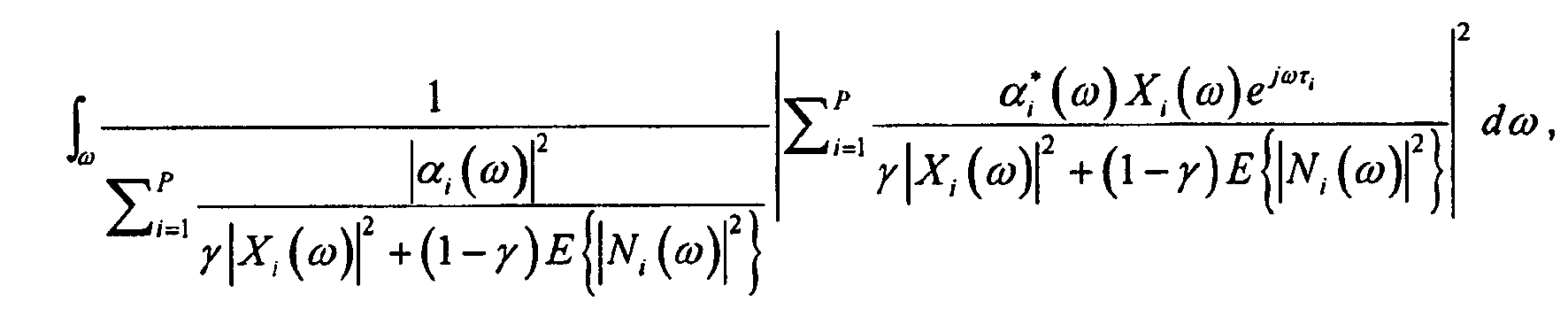
whereω denotes the frequency of interest, P is the total number of audio sensors i, αi (ω) is the magnitude sub-component of the audio sensor response, γ is a prescribed noise parameter, |Xi (ω)|2 is an audio sensor output signal power spectrum for the sensor signal Xi (ω), E{|Ni (ω)|2} is an expected environmental noise power spectrum of the signal X¡ (ω), * denotes a complex conjugate and τ i is a time of propagation of sound emanating from the sound source to the audio sensor i if the sound source were located at the candidate sound source location; anddesignating the candidate sound source location that maximizes the equation as the sound source location that produces a set of estimated sensor output signals that are the closest to the actual sensor output signals for the audio sensors as a whole. - The process of claim 2, wherein the process action of determining which candidate sound source location produces a set of estimated sensor output signals that are the closest to the actual sensor output signals for the audio sensors as a whole, comprises the actions of:for each candidate sound source location, computing the equation
 where ω denotes the frequency of interest, P is the total number of audio sensors i, γ is a prescribed noise parameter, |Xi (ω)|2 is an audio sensor output signal power spectrum for the sensor signal Xi (ω), E{|Ni (ω)|2} is an expected environmental noise power spectrum of the signal Xi (ω) and τ i is a time of propagation of sound emanating from the sound source to the audio sensor i if the sound source were located at the candidate sound source location; anddesignating the candidate sound source location that maximizes the equation as the sound source location that produces a set of estimated sensor output signals that are the closest to the actual sensor output signals for the audio sensors as a whole.
 - A system for estimating the location of a sound source in an environment exhibiting reverberation and environmental noise, comprising:a microphone array having two or more audio sensors placed so as to pick up sound emanating from the sound source (118);a general purpose computing device (100);a computer program comprising program modules executable by the computing device, wherein the computing device is directed by the program modules of the computer program to,
input a signal output by each of the audio sensors (500);
compute a frequency transform of each audio sensor output signal (502);
establish a set of candidate sound source locations (504), each of which represents a possible location of the sound source;
for each candidate sound source location and each audio sensor, compute the time of propagation τ i from the candidate sound source location to the audio sensor (518), wherein i denotes which audio sensor;
for each frequency of interest of each frequency transformed audio sensor output signal,
estimate an expected environmental noise power spectrum E{|Ni (ω)|2} of the signal Xi (ω) (508), wherein ω denotes which frequency of interest, and wherein the expected environmental noise power spectrum is the environmental noise power spectrum expected to be associated with the signal,
compute an audio sensor output signal power spectrum |Xi (ω)|2 for the signal Xi (ω) (510),
measure a magnitude sub-component of an audio sensor response α i (ω) of the sensor associated with the signal Xi (ω) (512);
for each candidate sound source location, compute the equation
where P is the total number of audio sensors, * denotes a complex conjugate, and γ is a prescribed noise parameter (522); and
designate the candidate sound source location that maximizes the equation as the estimated sound source location (530). - The system of claim 11, wherein the signals output by the microphone array are digital signals, and wherein the frequency of interest of each of the audio sensor output signals, the expected environmental noise power spectrum of each signal, the audio sensor output signal power spectrum of each signal and the magnitude component of the audio sensor response associated with the signal are frequency bins as defined by the digital signal, and wherein the equation is computed as a summation across all the frequency bins rather than as an integral across the frequencies.
- The system of claim 11, wherein the program module for computing a frequency transform of each audio sensor output signal, comprises an sub-module for limiting the frequency transform to just those frequencies known to be exhibited by the sound source, or
wherein the prescribed noise parameter γ is a value ranging between about 0.1 and about 0.5. - A system for estimating the location of a sound source in an environment exhibiting reverberation and environmental noise, comprising:a microphone array having two or more audio sensors placed so as to pick up sound emanating from the sound source (118);a general purpose computing device (100);a computer program comprising program modules executable by the computing device, wherein the computing device is directed by the program modules of the computer program to,
input a signal output by each of the audio sensors (500);
compute a frequency transform of each audio sensor output signal (502);
establish a set of candidate sound source locations (504), each of which represents a possible location of the sound source;
for each candidate sound source location and each audio sensor, compute the time of propagation τ i from the candidate sound source location to the audio sensor (518), wherein i denotes which audio sensor;
for each frequency of interest of each frequency transformed audio sensor output signal,
estimate an expected environmental noise power spectrum E{|Ni (ω)|2} of the signal Xi (ω) (508), wherein ω denotes which frequency of interest, and wherein the expected environmental noise power spectrum is the environmental noise power spectrum expected to be associated with the signal,
compute an audio sensor output signal power spectrum |Xi (ω)|2 for the signal Xi (ω) (510),
for each candidate sound source location, compute the equation
where P is the total number of audio sensors and γ is a prescribed noise parameter (524); and
designate the candidate sound source location that maximizes the equation as the estimated sound source location (530). - The system of claim 14, wherein the signals output by the microphone array are digital signals, and wherein the frequency of interest of each of the audio sensor output signals, the expected environmental noise power spectrum of each signal and the audio sensor output signal power spectrum of each signal are frequency bins as defined by the digital signal, and wherein the equation is computed as a summation across all the frequency bins rather than as an integral across the frequencies.
Applications Claiming Priority (2)
| Application Number | Priority Date | Filing Date | Title |
|---|---|---|---|
| US11/627,799 US8233353B2 (en) | 2007-01-26 | 2007-01-26 | Multi-sensor sound source localization |
| PCT/US2008/052139 WO2008092138A1 (en) | 2007-01-26 | 2008-01-26 | Multi-sensor sound source localization |
Publications (3)
| Publication Number | Publication Date |
|---|---|
| EP2123116A1 EP2123116A1 (en) | 2009-11-25 |
| EP2123116A4 EP2123116A4 (en) | 2012-09-19 |
| EP2123116B1 true EP2123116B1 (en) | 2014-06-11 |
Family
ID=39644902
Family Applications (1)
| Application Number | Title | Priority Date | Filing Date |
|---|---|---|---|
| EP08714034.9A Not-in-force EP2123116B1 (en) | 2007-01-26 | 2008-01-26 | Multi-sensor sound source localization |
Country Status (6)
| Country | Link |
|---|---|
| US (1) | US8233353B2 (en) |
| EP (1) | EP2123116B1 (en) |
| JP (3) | JP2010517047A (en) |
| CN (1) | CN101595739B (en) |
| TW (1) | TW200839737A (en) |
| WO (1) | WO2008092138A1 (en) |
Cited By (1)
| Publication number | Priority date | Publication date | Assignee | Title |
|---|---|---|---|---|
| DE102015002962A1 (en) | 2015-03-07 | 2016-09-08 | Hella Kgaa Hueck & Co. | Method for locating a signal source of a structure-borne sound signal, in particular a structure-borne noise signal generated by at least one damage event on a flat component |
Families Citing this family (38)
| Publication number | Priority date | Publication date | Assignee | Title |
|---|---|---|---|---|
| WO2007058130A1 (en) * | 2005-11-15 | 2007-05-24 | Yamaha Corporation | Teleconference device and sound emission/collection device |
| JP4816221B2 (en) * | 2006-04-21 | 2011-11-16 | ヤマハ株式会社 | Sound pickup device and audio conference device |
| WO2008056649A1 (en) * | 2006-11-09 | 2008-05-15 | Panasonic Corporation | Sound source position detector |
| KR101483269B1 (en) * | 2008-05-06 | 2015-01-21 | 삼성전자주식회사 | apparatus and method of voice source position search in robot |
| US8989882B2 (en) | 2008-08-06 | 2015-03-24 | At&T Intellectual Property I, L.P. | Method and apparatus for managing presentation of media content |
| EP2380033B1 (en) * | 2008-12-16 | 2017-05-17 | Koninklijke Philips N.V. | Estimating a sound source location using particle filtering |
| US8121618B2 (en) | 2009-10-28 | 2012-02-21 | Digimarc Corporation | Intuitive computing methods and systems |
| TWI417563B (en) * | 2009-11-20 | 2013-12-01 | Univ Nat Cheng Kung | An soc design for far-field sound localization |
| CN101762806B (en) * | 2010-01-27 | 2013-03-13 | 华为终端有限公司 | Sound source locating method and apparatus thereof |
| US8861756B2 (en) | 2010-09-24 | 2014-10-14 | LI Creative Technologies, Inc. | Microphone array system |
| US9100734B2 (en) | 2010-10-22 | 2015-08-04 | Qualcomm Incorporated | Systems, methods, apparatus, and computer-readable media for far-field multi-source tracking and separation |
| CN102147458B (en) * | 2010-12-17 | 2013-03-13 | 中国科学院声学研究所 | Method and device for estimating direction of arrival (DOA) of broadband sound source |
| WO2012092562A1 (en) | 2010-12-30 | 2012-07-05 | Ambientz | Information processing using a population of data acquisition devices |
| CN102809742B (en) | 2011-06-01 | 2015-03-18 | 杜比实验室特许公司 | Sound source localization equipment and method |
| HUP1200197A2 (en) * | 2012-04-03 | 2013-10-28 | Budapesti Mueszaki Es Gazdasagtudomanyi Egyetem | Method and arrangement for real time source-selective monitoring and mapping of enviromental noise |
| BR112015020150B1 (en) | 2013-02-26 | 2021-08-17 | Mediatek Inc. | APPLIANCE TO GENERATE A SPEECH SIGNAL, AND, METHOD TO GENERATE A SPEECH SIGNAL |
| US9251436B2 (en) | 2013-02-26 | 2016-02-02 | Mitsubishi Electric Research Laboratories, Inc. | Method for localizing sources of signals in reverberant environments using sparse optimization |
| EP2974373B1 (en) * | 2013-03-14 | 2019-09-25 | Apple Inc. | Acoustic beacon for broadcasting the orientation of a device |
| US20140328505A1 (en) * | 2013-05-02 | 2014-11-06 | Microsoft Corporation | Sound field adaptation based upon user tracking |
| GB2516314B (en) * | 2013-07-19 | 2017-03-08 | Canon Kk | Method and apparatus for sound sources localization with improved secondary sources localization |
| FR3011377B1 (en) * | 2013-10-01 | 2015-11-06 | Aldebaran Robotics | METHOD FOR LOCATING A SOUND SOURCE AND HUMANOID ROBOT USING SUCH A METHOD |
| US9544687B2 (en) * | 2014-01-09 | 2017-01-10 | Qualcomm Technologies International, Ltd. | Audio distortion compensation method and acoustic channel estimation method for use with same |
| CN103778288B (en) * | 2014-01-15 | 2017-05-17 | 河南科技大学 | Ant colony optimization-based near field sound source localization method under non-uniform array noise condition |
| US9774995B2 (en) * | 2014-05-09 | 2017-09-26 | Microsoft Technology Licensing, Llc | Location tracking based on overlapping geo-fences |
| US9685730B2 (en) | 2014-09-12 | 2017-06-20 | Steelcase Inc. | Floor power distribution system |
| WO2016097479A1 (en) | 2014-12-15 | 2016-06-23 | Zenniz Oy | Detection of acoustic events |
| US9584910B2 (en) | 2014-12-17 | 2017-02-28 | Steelcase Inc. | Sound gathering system |
| JP6729577B2 (en) * | 2015-06-26 | 2020-07-22 | 日本電気株式会社 | Signal detecting device, signal detecting method and program |
| US9407989B1 (en) | 2015-06-30 | 2016-08-02 | Arthur Woodrow | Closed audio circuit |
| US10393571B2 (en) | 2015-07-06 | 2019-08-27 | Dolby Laboratories Licensing Corporation | Estimation of reverberant energy component from active audio source |
| CN105785319B (en) * | 2016-05-20 | 2018-03-20 | 中国民用航空总局第二研究所 | Airdrome scene target acoustical localization method, apparatus and system |
| US20180317006A1 (en) | 2017-04-28 | 2018-11-01 | Qualcomm Incorporated | Microphone configurations |
| US10176808B1 (en) | 2017-06-20 | 2019-01-08 | Microsoft Technology Licensing, Llc | Utilizing spoken cues to influence response rendering for virtual assistants |
| EP3531090A1 (en) | 2018-02-27 | 2019-08-28 | Distran AG | Estimation of the sensitivity of a detector device comprising a transducer array |
| US11022511B2 (en) | 2018-04-18 | 2021-06-01 | Aron Kain | Sensor commonality platform using multi-discipline adaptable sensors for customizable applications |
| CN110035379B (en) * | 2019-03-28 | 2020-08-25 | 维沃移动通信有限公司 | Positioning method and terminal equipment |
| CN112346012A (en) * | 2020-11-13 | 2021-02-09 | 南京地平线机器人技术有限公司 | Sound source position determining method and device, readable storage medium and electronic equipment |
| CN116047413B (en) * | 2023-03-31 | 2023-06-23 | 长沙东玛克信息科技有限公司 | Audio accurate positioning method under closed reverberation environment |
Family Cites Families (29)
| Publication number | Priority date | Publication date | Assignee | Title |
|---|---|---|---|---|
| JPS60108779A (en) * | 1983-11-18 | 1985-06-14 | Matsushita Electric Ind Co Ltd | Sound source position measuring apparatus |
| JPH04238284A (en) * | 1991-01-22 | 1992-08-26 | Oki Electric Ind Co Ltd | Sound source position estimating device |
| JPH0545439A (en) * | 1991-08-12 | 1993-02-23 | Oki Electric Ind Co Ltd | Sound-source-position estimating apparatus |
| JP2570110B2 (en) * | 1993-06-08 | 1997-01-08 | 日本電気株式会社 | Underwater sound source localization system |
| JP3572594B2 (en) * | 1995-07-05 | 2004-10-06 | 晴夫 浜田 | Signal source search method and apparatus |
| JP2641417B2 (en) * | 1996-05-09 | 1997-08-13 | 安川商事株式会社 | Measurement device using spatio-temporal differentiation method |
| US6130949A (en) * | 1996-09-18 | 2000-10-10 | Nippon Telegraph And Telephone Corporation | Method and apparatus for separation of source, program recorded medium therefor, method and apparatus for detection of sound source zone, and program recorded medium therefor |
| DE19646055A1 (en) * | 1996-11-07 | 1998-05-14 | Thomson Brandt Gmbh | Method and device for mapping sound sources onto loudspeakers |
| JPH11304906A (en) * | 1998-04-20 | 1999-11-05 | Nippon Telegr & Teleph Corp <Ntt> | Sound-source estimation device and its recording medium with recorded program |
| JP2001352530A (en) * | 2000-06-09 | 2001-12-21 | Nippon Telegr & Teleph Corp <Ntt> | Communication conference system |
| JP2002091469A (en) * | 2000-09-19 | 2002-03-27 | Atr Onsei Gengo Tsushin Kenkyusho:Kk | Speech recognition device |
| JP4722347B2 (en) * | 2000-10-02 | 2011-07-13 | 中部電力株式会社 | Sound source exploration system |
| JP2002277228A (en) * | 2001-03-15 | 2002-09-25 | Kansai Electric Power Co Inc:The | Sound source position evaluating method |
| US7349005B2 (en) * | 2001-06-14 | 2008-03-25 | Microsoft Corporation | Automated video production system and method using expert video production rules for online publishing of lectures |
| US7130446B2 (en) * | 2001-12-03 | 2006-10-31 | Microsoft Corporation | Automatic detection and tracking of multiple individuals using multiple cues |
| JP4195267B2 (en) * | 2002-03-14 | 2008-12-10 | インターナショナル・ビジネス・マシーンズ・コーポレーション | Speech recognition apparatus, speech recognition method and program thereof |
| JP2004012151A (en) * | 2002-06-03 | 2004-01-15 | Matsushita Electric Ind Co Ltd | System of estimating direction of sound source |
| FR2841022B1 (en) * | 2002-06-12 | 2004-08-27 | Centre Nat Rech Scient | METHOD FOR LOCATING AN IMPACT ON A SURFACE AND DEVICE FOR IMPLEMENTING SAID METHOD |
| US7039199B2 (en) * | 2002-08-26 | 2006-05-02 | Microsoft Corporation | System and process for locating a speaker using 360 degree sound source localization |
| JP4247037B2 (en) * | 2003-01-29 | 2009-04-02 | 株式会社東芝 | Audio signal processing method, apparatus and program |
| US6882959B2 (en) * | 2003-05-02 | 2005-04-19 | Microsoft Corporation | System and process for tracking an object state using a particle filter sensor fusion technique |
| US6999593B2 (en) * | 2003-05-28 | 2006-02-14 | Microsoft Corporation | System and process for robust sound source localization |
| US7343289B2 (en) * | 2003-06-25 | 2008-03-11 | Microsoft Corp. | System and method for audio/video speaker detection |
| JP4080987B2 (en) * | 2003-10-30 | 2008-04-23 | 日本電信電話株式会社 | Echo / noise suppression method and multi-channel loudspeaker communication system |
| US6970796B2 (en) * | 2004-03-01 | 2005-11-29 | Microsoft Corporation | System and method for improving the precision of localization estimates |
| CN1808571A (en) * | 2005-01-19 | 2006-07-26 | 松下电器产业株式会社 | Acoustical signal separation system and method |
| CN1832633A (en) * | 2005-03-07 | 2006-09-13 | 华为技术有限公司 | Auditory localization method |
| US7583808B2 (en) * | 2005-03-28 | 2009-09-01 | Mitsubishi Electric Research Laboratories, Inc. | Locating and tracking acoustic sources with microphone arrays |
| CN1952684A (en) * | 2005-10-20 | 2007-04-25 | 松下电器产业株式会社 | Method and device for localization of sound source by microphone |
-
2007
- 2007-01-26 US US11/627,799 patent/US8233353B2/en active Active
-
2008
- 2008-01-23 TW TW097102575A patent/TW200839737A/en unknown
- 2008-01-26 CN CN2008800032518A patent/CN101595739B/en not_active Expired - Fee Related
- 2008-01-26 WO PCT/US2008/052139 patent/WO2008092138A1/en active Application Filing
- 2008-01-26 EP EP08714034.9A patent/EP2123116B1/en not_active Not-in-force
- 2008-01-26 JP JP2009547447A patent/JP2010517047A/en active Pending
-
2014
- 2014-10-29 JP JP2014220389A patent/JP6042858B2/en not_active Expired - Fee Related
-
2016
- 2016-08-19 JP JP2016161417A patent/JP6335985B2/en not_active Expired - Fee Related
Cited By (1)
| Publication number | Priority date | Publication date | Assignee | Title |
|---|---|---|---|---|
| DE102015002962A1 (en) | 2015-03-07 | 2016-09-08 | Hella Kgaa Hueck & Co. | Method for locating a signal source of a structure-borne sound signal, in particular a structure-borne noise signal generated by at least one damage event on a flat component |
Also Published As
| Publication number | Publication date |
|---|---|
| EP2123116A1 (en) | 2009-11-25 |
| CN101595739A (en) | 2009-12-02 |
| WO2008092138A1 (en) | 2008-07-31 |
| TW200839737A (en) | 2008-10-01 |
| JP2010517047A (en) | 2010-05-20 |
| US8233353B2 (en) | 2012-07-31 |
| EP2123116A4 (en) | 2012-09-19 |
| JP6335985B2 (en) | 2018-05-30 |
| JP2016218078A (en) | 2016-12-22 |
| JP6042858B2 (en) | 2016-12-14 |
| US20080181430A1 (en) | 2008-07-31 |
| CN101595739B (en) | 2012-11-14 |
| JP2015042989A (en) | 2015-03-05 |
Similar Documents
| Publication | Publication Date | Title |
|---|---|---|
| EP2123116B1 (en) | Multi-sensor sound source localization | |
| US7626889B2 (en) | Sensor array post-filter for tracking spatial distributions of signals and noise | |
| JP4912778B2 (en) | Method and system for modeling the trajectory of a signal source | |
| Argentieri et al. | A survey on sound source localization in robotics: From binaural to array processing methods | |
| Traa et al. | Multichannel source separation and tracking with RANSAC and directional statistics | |
| Di Carlo et al. | Mirage: 2d source localization using microphone pair augmentation with echoes | |
| Salvati et al. | Incident signal power comparison for localization of concurrent multiple acoustic sources | |
| Varanasi et al. | Near-field acoustic source localization using spherical harmonic features | |
| Nguyen et al. | Multilevel B-splines-based learning approach for sound source localization | |
| Adalbjörnsson et al. | Sparse localization of harmonic audio sources | |
| SongGong et al. | Acoustic source localization in the circular harmonic domain using deep learning architecture | |
| Vera-Diaz et al. | Towards domain independence in CNN-based acoustic localization using deep cross correlations | |
| Smaragdis et al. | Learning source trajectories using wrapped-phase hidden Markov models | |
| Firoozabadi et al. | Combination of nested microphone array and subband processing for multiple simultaneous speaker localization | |
| Wilson et al. | Improving audio source localization by learning the precedence effect | |
| Brutti et al. | An environment aware ML estimation of acoustic radiation pattern with distributed microphone pairs | |
| Banerjee et al. | A novel sound source localization method using a global-best guided cuckoo search algorithm for drone-based search and rescue operations | |
| US11835625B2 (en) | Acoustic-environment mismatch and proximity detection with a novel set of acoustic relative features and adaptive filtering | |
| da Silva et al. | Acoustic source DOA tracking using deep learning and MUSIC | |
| Vargas | Acoustic Source Localisation in constrained environments | |
| Ward et al. | Particle filtering algorithms for acoustic source localization | |
| Ramamurthy | Experimental evaluation of modified phase transform for sound source detection | |
| Ramadan et al. | Robust Sound Detection & Localization Algorithms for Robotics Applications | |
| Firoozabadi et al. | Multi-Speaker Localization by Central and Lateral Microphone Arrays Based on the Combination of 2D-SRP and Subband GEVD Algorithms | |
| Zaken et al. | Neural-Network-Based Direction-of-Arrival Estimation for Reverberant Speech-the Importance of Energetic, Temporal and Spatial Information |
Legal Events
| Date | Code | Title | Description |
|---|---|---|---|
| PUAI | Public reference made under article 153(3) epc to a published international application that has entered the european phase |
Free format text: ORIGINAL CODE: 0009012 |
|
| 17P | Request for examination filed |
Effective date: 20090727 |
|
| AK | Designated contracting states |
Kind code of ref document: A1 Designated state(s): AT BE BG CH CY CZ DE DK EE ES FI FR GB GR HR HU IE IS IT LI LT LU LV MC MT NL NO PL PT RO SE SI SK TR |
|
| DAX | Request for extension of the european patent (deleted) | ||
| A4 | Supplementary search report drawn up and despatched |
Effective date: 20120820 |
|
| RIC1 | Information provided on ipc code assigned before grant |
Ipc: H04R 1/40 20060101ALI20120813BHEP Ipc: H04S 7/00 20060101AFI20120813BHEP Ipc: H04R 3/00 20060101ALI20120813BHEP Ipc: H04R 1/20 20060101ALI20120813BHEP |
|
| GRAP | Despatch of communication of intention to grant a patent |
Free format text: ORIGINAL CODE: EPIDOSNIGR1 |
|
| INTG | Intention to grant announced |
Effective date: 20131217 |
|
| GRAS | Grant fee paid |
Free format text: ORIGINAL CODE: EPIDOSNIGR3 |
|
| GRAA | (expected) grant |
Free format text: ORIGINAL CODE: 0009210 |
|
| AK | Designated contracting states |
Kind code of ref document: B1 Designated state(s): AT BE BG CH CY CZ DE DK EE ES FI FR GB GR HR HU IE IS IT LI LT LU LV MC MT NL NO PL PT RO SE SI SK TR |
|
| REG | Reference to a national code |
Ref country code: GB Ref legal event code: FG4D |
|
| REG | Reference to a national code |
Ref country code: CH Ref legal event code: EP |
|
| REG | Reference to a national code |
Ref country code: IE Ref legal event code: FG4D |
|
| REG | Reference to a national code |
Ref country code: AT Ref legal event code: REF Ref document number: 672727 Country of ref document: AT Kind code of ref document: T Effective date: 20140715 |
|
| REG | Reference to a national code |
Ref country code: DE Ref legal event code: R096 Ref document number: 602008032693 Country of ref document: DE Effective date: 20140724 |
|
| REG | Reference to a national code |
Ref country code: NL Ref legal event code: T3 |
|
| PG25 | Lapsed in a contracting state [announced via postgrant information from national office to epo] |
Ref country code: NO Free format text: LAPSE BECAUSE OF FAILURE TO SUBMIT A TRANSLATION OF THE DESCRIPTION OR TO PAY THE FEE WITHIN THE PRESCRIBED TIME-LIMIT Effective date: 20140911 Ref country code: LT Free format text: LAPSE BECAUSE OF FAILURE TO SUBMIT A TRANSLATION OF THE DESCRIPTION OR TO PAY THE FEE WITHIN THE PRESCRIBED TIME-LIMIT Effective date: 20140611 Ref country code: FI Free format text: LAPSE BECAUSE OF FAILURE TO SUBMIT A TRANSLATION OF THE DESCRIPTION OR TO PAY THE FEE WITHIN THE PRESCRIBED TIME-LIMIT Effective date: 20140611 Ref country code: GR Free format text: LAPSE BECAUSE OF FAILURE TO SUBMIT A TRANSLATION OF THE DESCRIPTION OR TO PAY THE FEE WITHIN THE PRESCRIBED TIME-LIMIT Effective date: 20140912 |
|
| REG | Reference to a national code |
Ref country code: AT Ref legal event code: MK05 Ref document number: 672727 Country of ref document: AT Kind code of ref document: T Effective date: 20140611 |
|
| REG | Reference to a national code |
Ref country code: LT Ref legal event code: MG4D |
|
| PG25 | Lapsed in a contracting state [announced via postgrant information from national office to epo] |
Ref country code: SE Free format text: LAPSE BECAUSE OF FAILURE TO SUBMIT A TRANSLATION OF THE DESCRIPTION OR TO PAY THE FEE WITHIN THE PRESCRIBED TIME-LIMIT Effective date: 20140611 Ref country code: HR Free format text: LAPSE BECAUSE OF FAILURE TO SUBMIT A TRANSLATION OF THE DESCRIPTION OR TO PAY THE FEE WITHIN THE PRESCRIBED TIME-LIMIT Effective date: 20140611 Ref country code: LV Free format text: LAPSE BECAUSE OF FAILURE TO SUBMIT A TRANSLATION OF THE DESCRIPTION OR TO PAY THE FEE WITHIN THE PRESCRIBED TIME-LIMIT Effective date: 20140611 |
|
| PG25 | Lapsed in a contracting state [announced via postgrant information from national office to epo] |
Ref country code: EE Free format text: LAPSE BECAUSE OF FAILURE TO SUBMIT A TRANSLATION OF THE DESCRIPTION OR TO PAY THE FEE WITHIN THE PRESCRIBED TIME-LIMIT Effective date: 20140611 Ref country code: CZ Free format text: LAPSE BECAUSE OF FAILURE TO SUBMIT A TRANSLATION OF THE DESCRIPTION OR TO PAY THE FEE WITHIN THE PRESCRIBED TIME-LIMIT Effective date: 20140611 Ref country code: SK Free format text: LAPSE BECAUSE OF FAILURE TO SUBMIT A TRANSLATION OF THE DESCRIPTION OR TO PAY THE FEE WITHIN THE PRESCRIBED TIME-LIMIT Effective date: 20140611 Ref country code: PT Free format text: LAPSE BECAUSE OF FAILURE TO SUBMIT A TRANSLATION OF THE DESCRIPTION OR TO PAY THE FEE WITHIN THE PRESCRIBED TIME-LIMIT Effective date: 20141013 Ref country code: RO Free format text: LAPSE BECAUSE OF FAILURE TO SUBMIT A TRANSLATION OF THE DESCRIPTION OR TO PAY THE FEE WITHIN THE PRESCRIBED TIME-LIMIT Effective date: 20140611 Ref country code: ES Free format text: LAPSE BECAUSE OF FAILURE TO SUBMIT A TRANSLATION OF THE DESCRIPTION OR TO PAY THE FEE WITHIN THE PRESCRIBED TIME-LIMIT Effective date: 20140611 |
|
| PG25 | Lapsed in a contracting state [announced via postgrant information from national office to epo] |
Ref country code: IS Free format text: LAPSE BECAUSE OF FAILURE TO SUBMIT A TRANSLATION OF THE DESCRIPTION OR TO PAY THE FEE WITHIN THE PRESCRIBED TIME-LIMIT Effective date: 20141011 Ref country code: PL Free format text: LAPSE BECAUSE OF FAILURE TO SUBMIT A TRANSLATION OF THE DESCRIPTION OR TO PAY THE FEE WITHIN THE PRESCRIBED TIME-LIMIT Effective date: 20140611 Ref country code: AT Free format text: LAPSE BECAUSE OF FAILURE TO SUBMIT A TRANSLATION OF THE DESCRIPTION OR TO PAY THE FEE WITHIN THE PRESCRIBED TIME-LIMIT Effective date: 20140611 |
|
| REG | Reference to a national code |
Ref country code: DE Ref legal event code: R082 Ref document number: 602008032693 Country of ref document: DE Representative=s name: GRUENECKER PATENT- UND RECHTSANWAELTE PARTG MB, DE |
|
| REG | Reference to a national code |
Ref country code: DE Ref legal event code: R097 Ref document number: 602008032693 Country of ref document: DE |
|
| REG | Reference to a national code |
Ref country code: CH Ref legal event code: PUE Owner name: MICROSOFT TECHNOLOGY LICENSING, LLC, US Free format text: FORMER OWNER: MICROSOFT CORPORATION, US |
|
| REG | Reference to a national code |
Ref country code: GB Ref legal event code: 732E Free format text: REGISTERED BETWEEN 20150319 AND 20150325 |
|
| REG | Reference to a national code |
Ref country code: DE Ref legal event code: R081 Ref document number: 602008032693 Country of ref document: DE Owner name: MICROSOFT TECHNOLOGY LICENSING, LLC, REDMOND, US Free format text: FORMER OWNER: MICROSOFT CORP., REDMOND, WASH., US Effective date: 20150310 Ref country code: DE Ref legal event code: R082 Ref document number: 602008032693 Country of ref document: DE Representative=s name: GRUENECKER PATENT- UND RECHTSANWAELTE PARTG MB, DE Effective date: 20150310 |
|
| PLBE | No opposition filed within time limit |
Free format text: ORIGINAL CODE: 0009261 |
|
| STAA | Information on the status of an ep patent application or granted ep patent |
Free format text: STATUS: NO OPPOSITION FILED WITHIN TIME LIMIT |
|
| RAP2 | Party data changed (patent owner data changed or rights of a patent transferred) |
Owner name: MICROSOFT TECHNOLOGY LICENSING, LLC |
|
| PG25 | Lapsed in a contracting state [announced via postgrant information from national office to epo] |
Ref country code: IT Free format text: LAPSE BECAUSE OF FAILURE TO SUBMIT A TRANSLATION OF THE DESCRIPTION OR TO PAY THE FEE WITHIN THE PRESCRIBED TIME-LIMIT Effective date: 20140611 Ref country code: DK Free format text: LAPSE BECAUSE OF FAILURE TO SUBMIT A TRANSLATION OF THE DESCRIPTION OR TO PAY THE FEE WITHIN THE PRESCRIBED TIME-LIMIT Effective date: 20140611 |
|
| 26N | No opposition filed |
Effective date: 20150312 |
|
| REG | Reference to a national code |
Ref country code: FR Ref legal event code: TP Owner name: MICROSOFT TECHNOLOGY LICENSING, LLC, US Effective date: 20150429 |
|
| REG | Reference to a national code |
Ref country code: DE Ref legal event code: R097 Ref document number: 602008032693 Country of ref document: DE Effective date: 20150312 |
|
| PG25 | Lapsed in a contracting state [announced via postgrant information from national office to epo] |
Ref country code: BE Free format text: LAPSE BECAUSE OF FAILURE TO SUBMIT A TRANSLATION OF THE DESCRIPTION OR TO PAY THE FEE WITHIN THE PRESCRIBED TIME-LIMIT Effective date: 20140611 |
|
| REG | Reference to a national code |
Ref country code: NL Ref legal event code: SD Effective date: 20150706 |
|
| PG25 | Lapsed in a contracting state [announced via postgrant information from national office to epo] |
Ref country code: SI Free format text: LAPSE BECAUSE OF FAILURE TO SUBMIT A TRANSLATION OF THE DESCRIPTION OR TO PAY THE FEE WITHIN THE PRESCRIBED TIME-LIMIT Effective date: 20140611 |
|
| REG | Reference to a national code |
Ref country code: CH Ref legal event code: PL |
|
| PG25 | Lapsed in a contracting state [announced via postgrant information from national office to epo] |
Ref country code: LU Free format text: LAPSE BECAUSE OF FAILURE TO SUBMIT A TRANSLATION OF THE DESCRIPTION OR TO PAY THE FEE WITHIN THE PRESCRIBED TIME-LIMIT Effective date: 20150126 |
|
| PG25 | Lapsed in a contracting state [announced via postgrant information from national office to epo] |
Ref country code: MC Free format text: LAPSE BECAUSE OF FAILURE TO SUBMIT A TRANSLATION OF THE DESCRIPTION OR TO PAY THE FEE WITHIN THE PRESCRIBED TIME-LIMIT Effective date: 20140611 |
|
| PG25 | Lapsed in a contracting state [announced via postgrant information from national office to epo] |
Ref country code: CH Free format text: LAPSE BECAUSE OF NON-PAYMENT OF DUE FEES Effective date: 20150131 Ref country code: LI Free format text: LAPSE BECAUSE OF NON-PAYMENT OF DUE FEES Effective date: 20150131 |
|
| REG | Reference to a national code |
Ref country code: IE Ref legal event code: MM4A |
|
| REG | Reference to a national code |
Ref country code: FR Ref legal event code: PLFP Year of fee payment: 9 |
|
| PG25 | Lapsed in a contracting state [announced via postgrant information from national office to epo] |
Ref country code: IE Free format text: LAPSE BECAUSE OF NON-PAYMENT OF DUE FEES Effective date: 20150126 |
|
| REG | Reference to a national code |
Ref country code: FR Ref legal event code: PLFP Year of fee payment: 10 |
|
| PG25 | Lapsed in a contracting state [announced via postgrant information from national office to epo] |
Ref country code: MT Free format text: LAPSE BECAUSE OF FAILURE TO SUBMIT A TRANSLATION OF THE DESCRIPTION OR TO PAY THE FEE WITHIN THE PRESCRIBED TIME-LIMIT Effective date: 20140611 |
|
| PG25 | Lapsed in a contracting state [announced via postgrant information from national office to epo] |
Ref country code: BG Free format text: LAPSE BECAUSE OF FAILURE TO SUBMIT A TRANSLATION OF THE DESCRIPTION OR TO PAY THE FEE WITHIN THE PRESCRIBED TIME-LIMIT Effective date: 20140611 Ref country code: HU Free format text: LAPSE BECAUSE OF FAILURE TO SUBMIT A TRANSLATION OF THE DESCRIPTION OR TO PAY THE FEE WITHIN THE PRESCRIBED TIME-LIMIT; INVALID AB INITIO Effective date: 20080126 |
|
| PG25 | Lapsed in a contracting state [announced via postgrant information from national office to epo] |
Ref country code: CY Free format text: LAPSE BECAUSE OF FAILURE TO SUBMIT A TRANSLATION OF THE DESCRIPTION OR TO PAY THE FEE WITHIN THE PRESCRIBED TIME-LIMIT Effective date: 20140611 |
|
| PG25 | Lapsed in a contracting state [announced via postgrant information from national office to epo] |
Ref country code: TR Free format text: LAPSE BECAUSE OF FAILURE TO SUBMIT A TRANSLATION OF THE DESCRIPTION OR TO PAY THE FEE WITHIN THE PRESCRIBED TIME-LIMIT Effective date: 20140611 |
|
| REG | Reference to a national code |
Ref country code: FR Ref legal event code: PLFP Year of fee payment: 11 |
|
| PGFP | Annual fee paid to national office [announced via postgrant information from national office to epo] |
Ref country code: FR Payment date: 20201210 Year of fee payment: 14 |
|
| PGFP | Annual fee paid to national office [announced via postgrant information from national office to epo] |
Ref country code: NL Payment date: 20210113 Year of fee payment: 14 |
|
| PGFP | Annual fee paid to national office [announced via postgrant information from national office to epo] |
Ref country code: GB Payment date: 20210113 Year of fee payment: 14 Ref country code: DE Payment date: 20210112 Year of fee payment: 14 |
|
| REG | Reference to a national code |
Ref country code: DE Ref legal event code: R119 Ref document number: 602008032693 Country of ref document: DE |
|
| REG | Reference to a national code |
Ref country code: NL Ref legal event code: MM Effective date: 20220201 |
|
| GBPC | Gb: european patent ceased through non-payment of renewal fee |
Effective date: 20220126 |
|
| PG25 | Lapsed in a contracting state [announced via postgrant information from national office to epo] |
Ref country code: NL Free format text: LAPSE BECAUSE OF NON-PAYMENT OF DUE FEES Effective date: 20220201 Ref country code: GB Free format text: LAPSE BECAUSE OF NON-PAYMENT OF DUE FEES Effective date: 20220126 Ref country code: DE Free format text: LAPSE BECAUSE OF NON-PAYMENT OF DUE FEES Effective date: 20220802 |
|
| PG25 | Lapsed in a contracting state [announced via postgrant information from national office to epo] |
Ref country code: FR Free format text: LAPSE BECAUSE OF NON-PAYMENT OF DUE FEES Effective date: 20220131 |