EP2136477B1 - Device and associated method for crosstalk estimation - Google Patents
Device and associated method for crosstalk estimation Download PDFInfo
- Publication number
- EP2136477B1 EP2136477B1 EP08290565A EP08290565A EP2136477B1 EP 2136477 B1 EP2136477 B1 EP 2136477B1 EP 08290565 A EP08290565 A EP 08290565A EP 08290565 A EP08290565 A EP 08290565A EP 2136477 B1 EP2136477 B1 EP 2136477B1
- Authority
- EP
- European Patent Office
- Prior art keywords
- crosstalk
- lines
- subset
- communication lines
- pilot sequence
- Prior art date
- Legal status (The legal status is an assumption and is not a legal conclusion. Google has not performed a legal analysis and makes no representation as to the accuracy of the status listed.)
- Active
Links
Images

Classifications
-
- H—ELECTRICITY
- H04—ELECTRIC COMMUNICATION TECHNIQUE
- H04L—TRANSMISSION OF DIGITAL INFORMATION, e.g. TELEGRAPHIC COMMUNICATION
- H04L27/00—Modulated-carrier systems
- H04L27/26—Systems using multi-frequency codes
- H04L27/2601—Multicarrier modulation systems
- H04L27/2602—Signal structure
- H04L27/261—Details of reference signals
-
- H—ELECTRICITY
- H04—ELECTRIC COMMUNICATION TECHNIQUE
- H04B—TRANSMISSION
- H04B3/00—Line transmission systems
- H04B3/02—Details
- H04B3/32—Reducing cross-talk, e.g. by compensating
-
- H—ELECTRICITY
- H04—ELECTRIC COMMUNICATION TECHNIQUE
- H04B—TRANSMISSION
- H04B3/00—Line transmission systems
- H04B3/02—Details
- H04B3/46—Monitoring; Testing
-
- H—ELECTRICITY
- H04—ELECTRIC COMMUNICATION TECHNIQUE
- H04B—TRANSMISSION
- H04B3/00—Line transmission systems
- H04B3/02—Details
- H04B3/46—Monitoring; Testing
- H04B3/487—Testing crosstalk effects
-
- H—ELECTRICITY
- H04—ELECTRIC COMMUNICATION TECHNIQUE
- H04L—TRANSMISSION OF DIGITAL INFORMATION, e.g. TELEGRAPHIC COMMUNICATION
- H04L1/00—Arrangements for detecting or preventing errors in the information received
- H04L1/20—Arrangements for detecting or preventing errors in the information received using signal quality detector
-
- H—ELECTRICITY
- H04—ELECTRIC COMMUNICATION TECHNIQUE
- H04L—TRANSMISSION OF DIGITAL INFORMATION, e.g. TELEGRAPHIC COMMUNICATION
- H04L25/00—Baseband systems
- H04L25/02—Details ; arrangements for supplying electrical power along data transmission lines
- H04L25/0202—Channel estimation
- H04L25/0204—Channel estimation of multiple channels
Definitions
- the present invention generally relates to precoding on communication lines and in particular to a device and method for estimating crosstalk information which can be used in precoding on communication lines such as very high speed digital subscriber lines (VDSL) and VDSL2 lines.
- VDSL very high speed digital subscriber lines
- VDSL2 lines very high speed digital subscriber lines
- Various communication lines which operate within each others' vicinity may induce signals on each other.
- two communication lines such as two VDSL2 lines which are collocated next to each other induce a signal in each other.
- Such signal is called crosstalk and has an influence on the quality of communication on these lines. Due to the induced crosstalk and noise from other sources in the surroundings of the communication line, the data transported on these lines may be affected or corrupted by the crosstalk and noise. Corrupted data needs to be corrected or transmitted again before the receiver can process the data.
- the amount of corrupted data may be reduced ,the need for error corrections or retransmissions is reduced, and the rate at which information can be reliably communicated is increased.
- Each communication line is a possible disturber line which induces crosstalk in one or more victim lines.
- the test signals can be characterized by the way in which power is allocated to one or more tones or frequencies. For instance a test signal may be transmitted using a particular power level over a small frequency range. The victim line may notice this power in that frequency range and be able to determine the amplitude of that power.
- the amplitude of the induced influence of crosstalk on a particular line is a good reference to determine how strong particular crosstalkers are or which frequencies or tones are susceptible to the crosstalk of certain crosstalkers.
- each possible communication line which may induce crosstalk also called a crosstalker
- emits a distinct power spectrum as test signal it is possible to detect which crosstalker or crosstalkers are inducing noise on a given victim line.
- the information obtained by such measurements can then be used to group communication lines in physical groups or logical groups or binders, define the transmit spectra on the communication lines, etc.
- This enables a network operator to configure lines in such a way that crosstalk is avoided as much as possible or that the effects of crosstalk are reduced. For instance by selecting a transmit spectrum on a victim line in such a way that frequencies or tones with strong crosstalk influences from offender lines are avoided, the quality of the victim line is improved and the crosstalk is reduced.
- a problem with the above given approach is that it is difficult to adjust transmit power spectra of lines in operation. Such changes reduce the throughput of the line significantly and may even lead to a service outage for a user when a line has to be reconfigured.
- the above described technique can only be used for upcoming lines which may also be called joining lines and may not be able to handle significant changes in crosstalk once the line is in operation.
- the measurements can be performed relatively easily by transmitting a particular power on the possible disturber lines.
- PSD power spectral density
- the phase of the crosstalk signal cannot be assessed using such a technique. This means that the exact crosstalk channel, described mathematically by complex coefficients having both magnitude and phase, is not known.
- Precoding techniques are based on transmitting an additional signal on top of the data signal which is used to compensate the crosstalk on a victim line from external sources.
- precoding can be used to compensate for the effects of crosstalk on a communication channel.
- Precoding techniques are based on crosstalk channel information that includes both amplitude and phase information. Such information can be obtained from measurements such as slicer error or SNR.
- measurements for precoding is the use of pilot sequences and error feedback.
- error feedback refers to a means by which the receiver of a communication system such as a CPE communicates to the transmitter of the communication system such as a DSLAM one or more received signal errors, or values derived from received signal errors. Received signal errors can be defined as the difference between the received signal and an estimate of the transmitted signal.
- a pilot sequence in particular in DSL technology, is a series of pilot signals which are transmitted for instance downstream from the Digital Subscriber Line Access Multiplexer (DSLAM) to the Customer Premises Equipment (CPE) and can for instance be described as a sequence of constellation points in a 4-QAM constellation.
- DSLAM Digital Subscriber Line Access Multiplexer
- CPE Customer Premises Equipment
- All active sub-carriers are modulated by two bits, either both zero (00) or both one (11), from the sync-frame using 4-QAM.
- the constellation points are rotated using a quadrant scrambler and due to the operation of the scrambler, it only has to be taken into account when crosstalk coefficients are determined.
- the constellation points 00 or 11 are transmitted downstream during a sync symbol on the communication line.
- Such sync symbols are periodically transmitted, typically after every 256 data symbols.
- the constellation points 00 and 11 have a complex representation being "+1 + j" for 00 and "-1 - j" for 11.
- the constellation point 00 will be represented as '1' and the constellation point 11 will be represented as '-1'.
- a pilot sequence is a series of such constellation points, each transmitted in a separate sync symbol.
- a pilot sequence may consist of a sequence of 1 and -1 which is transmitted over the communication line, each sync symbol containing one of the points in the sequence. Since these points are defined and thus known to the receiver, it is possible to determine the difference between the expected symbol and the actual received symbol. This difference, which includes interference and noise can then be fed back to the DSLAM. The DSLAM is then able to correlate the error feedback and the pilot sequence in order to obtain the amplitude and phase of the crosstalk from one line to another line.
- a first drawback of the existing solution is that the estimation requires a long period of time when the number of communication lines in the precoding group is high.
- Large precoding groups also require a large amount of processing power and storage to store and process all the error feedback information and to combine transmitted pilot sequences with the error feedback to obtain an estimation of the crosstalk.
- a second drawback is found in a scenario where there are strong and weak crosstalkers in a precoding group. Some offender lines affect victim lines significantly more strongly than other offender lines. The influence of the weaker crosstalkers may therefore be irrelevant as their influence is negligible compared to that of the strong crosstalkers.
- the existing solutions devote equal time and computation to determining strong and weak crosstalkers and generally provide a complete estimation of all the crosstalk coefficients, which may be a waste of computational power and time because information from the strong crosstalkers alone may be sufficient to perform precoding in the precoding group.
- a third drawback is that when a joining communication line is initialized, crosstalk estimates are required for that communication line and in particular the influence of that line on other lines in the precoding group is of importance.
- the existing solutions are only able to estimate crosstalk for the entire group which means that when a line joins, it may take some time before sufficient information is available to configure the line and to perform accurate precoding.
- precoding is a new technique which is introduced to VDSL2 in the G.Vector extension thereof.
- G.Vector the G.Vector extension thereof.
- Communication lines which only support the VDSL2 standard specification are called legacy lines.
- the sync symbols are defined in the VDSL2 standard specification for legacy lines. This means that transmitting a pilot sequence on a legacy line may conflict with the standard specification.
- legacy lines are generally unable to communicate errors measured on the sync symbols to the DSLAM..
- the existing systems have difficulties in obtaining crosstalk information in a precoding group which consists of both legacy lines and vector-enabled lines.
- WO2008/02496 a system and method for MIMO precoding in an xDSL system is disclosed.
- Crosstalk estimation and compensation through precoding is discussed.
- the application describes what need to be done for crosstalk cancellation in case suddenly a new user appears (i.e. a new communication line comes up) for which no precoding has been performed yet.
- a crosstalk estimation device for estimating crosstalk between communication lines in a precoding group comprising:
- the crosstalk estimation device may further comprise means for selecting said pilot sequence based on the number of communication lines in the subset.
- the present invention is based on the insight that the length of a pilot sequence (L) depends on the number of communication lines whereon a pilot sequence is transmitted (M) to determine crosstalk coefficients.
- L the length of a pilot sequence
- M the number of communication lines whereon a pilot sequence is transmitted
- the pilot sequence has a large length. For instance if a precoding group consists of 50 lines, the pilot sequences must be at least 51 symbols long. Thus the prior art solutions would need to wait until those 51 symbols have been transmitted and error feedback of a 51 symbols has been received by the transmitter. In addition to the delay of transmitting those symbols and receiving the error feedback for all those symbols, this also requires a significant amount of storage and processing power. Error feedback on each symbol is received from each line, thus 50 lines have to provide error feedback information on 51 symbols.
- the selection of the subset with K lines reduces the number of M lines whereon a pilot sequence is transmitted.
- the computational power and storage requirements are reduced over the prior art sequences.
- a precoding group consists of 50 lines and a subset is 5 lines, the system still needs to obtain information from those 50 lines. However, each of these lines only has to provide error feedback over 6 symbols instead of 51 which is a large reduction.
- a feedback subset may be selected from the precoding group, as an alternative to obtaining error feedback from all lines in the precoding group.
- the feedback subset may overlap with the subset selected for transporting the pilot sequences or may consist of lines whereon no typical pilot sequence is transmitted. Having two subsets, one of lines whereon the pilot sequences are transmitted and one whereon error feedback is collected may reduce the required processing and storage even more. In such scenario, both the length of the pilot sequences is reduced and the number of lines which provide feedback.
- An important advantage of the present invention can be found in scenarios where a particular joining line in the precoding group changes from an inactive line to an active line.
- the error feedback measurement on lines may be something which is performed automatically or which may be coordinated.
- a receiver such as a CPE may always perform measurements on received signals and provide error feedback to a transmitter such as a DSLAM based on those measurements.
- the receiver or CPE may perform those measurements on every signal or on particular signals or symbols.
- a transmitter or DSLAM may instruct the receiver or CPE to perform error measurements on a certain signal or symbol for a particular period of time or number of symbols or until the DSLAM instructs the receiver or CPE to stop measurements.
- a DSLAM is able to determine crosstalk information by simply initiating the transmission of pilot sequences as the error feedback will be available anyway.
- the error feedback information may be transmitted back as soon as it is available or may be collected at the CPE side until all measurements are performed.
- the advantage of feedback as soon as available is that each error feedback communication requires a small piece of the available bandwidth on the communication line whereas sending all the data back in a single transmission may require a higher peak bandwidth.
- the DSLAM may be able to request the error feedback information from the CPE or the CPE may deliver the information to the DSLAM automatically.
- signals which are transported on communication lines which are not part of the subset are not considered pilot sequences.
- Communication lines which are not part of the selected subset typically will also transport a particular signal while the lines in the subset transport their pilot sequence.
- pilot sequences are transported in the sync symbol on each line
- the lines of the precoding group not part of the subset may transport a symbol in their sync symbol.
- pilot sequences When pilot sequences are equal to or are strongly correlated with the signals transported in the sync symbols of lines not in the subset, it is difficult or impossible to accurately estimate crosstalk coefficients from lines in the subset, using error feedback.
- pilot sequences are orthogonal to the signals transported in the sync symbols of lines not in the subset, these latter signals do not interfere at all with the ability to estimate crosstalk coefficients from lines in the subset, using error feedback.
- the crosstalk estimation device may further comprise means for estimating crosstalk based on a correlation between the error feedback and the pilot sequence.
- the device which transmits the pilot sequences such as a DSLAM is aware of the transmitted pilot sequences.
- the device By receiving the error feedback information from the device which receives the pilot sequences such as a CPE, the device is able to determine the crosstalk coefficients of the crosstalk channels between the lines whereon pilot sequences are transmitted and the lines wherefrom error feedback information is used.
- the crosstalk coefficients can be determined based on a correlation between the transmitted pilot sequence and the received error feedback. The correlation ensures that an exact estimation of the crosstalk coefficients is obtained and that the crosstalk channels are characterized accurately. Such accurate information can then be used to adapt the precoding in order to substantially eliminate interference from existing crosstalk channels.
- the transmission means of the crosstalk estimation device may be adapted for transmitting a distinct pilot sequence on each of the communication lines in the subset.
- the pilot sequence may be a non-constant sequence.
- Distinct pilot sequences are pilot sequences such that no two pilot sequences are identical.
- the sequences are preferably made up out of 1 or -1 and frequent changes are preferred. Signals which are generally constant, for instance sequences with only one change from 1 to -1 or vice versa) may resemble control signals on communication lines and may therefore lead to problems and should be avoided.
- the transmission means of the crosstalk estimation device may be adapted to transmit the pilot sequence in one or more sync symbols.
- crosstalk estimation device may further comprise means for inducing an additional sync-flag into the communication lines.
- the G.Vector community considers transmitting the pilot sequences on the sync symbol which is transmitted via a communication line.
- Legacy lines use the sync symbol to transport sync-flags from transmitter (such as a DSLAM) to receiver (such as CPE).
- transmitter such as a DSLAM
- CPE receiver
- a sync-flag is typically a change in the sign in the sync symbol, either from 1 to -1 or from -1 to 1 whereas otherwise this symbol is constant.
- the use of the sync symbols is not defined in a standard specification and thus these symbols could be used for other purposes such as transmitting pilot sequences.
- legacy lines do not provide the functionality to measure error signals on the sync symbols and to provide error feedback to the transmitter or DSLAM, it is not possible to use the error feedback method to determine the crosstalk induced on these lines by other lines. However by inducing additional sync-flags, it is possible to effectively transmit a pilot sequence over legacy lines. Thus by providing means for inducing sync-flags, it is possible to determine the crosstalk induced by a legacy line on a communication line operating according to the G.Vector specifications also called a vector enabled line. Vector enabled lines are able to determine error information on received sync symbols and are able to feed back such error information to the transmitter.
- Sync-symbols sent from the DSLAM at the CO to the CPE over a legacy line are interpreted by the CPE according to the standard specification.
- any sync-symbol which is sent as part of a pilot sequence is interpreted in a standardised way by the CPE.
- the DSLAM may induce additional sync-flags on the line which can then be used as elements of a pilot sequence.
- a first way of inducing a sync-flag which can be used as part of a pilot sequence is by reducing the power from the DSLAM side on one or more tones. By reducing the power on a small number of tones, the effect of the power reduction is negligible but a bitswap is called for.
- the CPE will request a bit swap.
- Such a request has to be acknowledged by the DSLAM via a sync-flag sent to the CPE.
- This sync-flag could be used as an element in the pilot sequence.
- the DSLAM could just transmit an unexpected sync-flag to the CPE. If the CPE does not expect such a sync-flag, for instance because no OLR request was made, it may discard the sync-flag.
- These two forms of inducing can be used to transmit the pilot sequence and thus provide information on the crosstalk influence from a legacy line on a vector enabled line. However this also means an overloading of the sync-symbols and additional load on the CPE and the control channel.
- induced sync-flags may therefore be beneficial to limit the use of induced sync-flags where possible. It can be beneficial to use small subsets and short sequences when estimating crosstalk from legacy lines, because the legacy lines are only required to send induced sync-flags when they belong to the subset, and they do not need to send induced sync-flags when they do not belong to the subset.
- the technique of inducing sync-flags is advantageous in that it enables the transmission of pilot sequences over legacy lines.
- crosstalk information is available from vector-enabled lines to vector-enabled lines and from legacy lines to vector-enabled lines.
- complete crosstalk information is available for the vector-enabled lines which allows the use of precoding on all the vector-enabled lines in the precoding group.
- the crosstalk estimation device may further comprise means for selecting a tone subset of one or more tones for each communication line in the subset of communication lines and means for transmitting the pilot sequence only in the tone subset.
- crosstalk estimation device may further comprise means for interpolating error feedback information and/or crosstalk coefficient estimates for tones not in the tone subset.
- the same element of the pilot sequence assigned to that communication line would be sent on each tone during the sync symbol.
- the assigned pilot sequence for a communication line in the subset was [1,1,-1,-1]
- the transmitter would send a "1” on all tones, then later send the value "1” on all tones, then send "-1” on all tones and finally send "-1” on all tones.
- this 1 or -1 would be sent during a sync symbol which alternates with data symbols being transmitted on the line.
- a general scheme for creating pilot sequences for such a system works as follows. There are M lines and a subset of K lines is selected for estimation. K pilot sequences, preferably mutually orthogonal pilot sequences, of length L ⁇ K+1 are selected (using, for example, Walsh-Hadamard sequences). With these parameters, the estimation procedure takes a set of pilot sequences of length L to obtain an estimate for K lines.
- K preferably mutually orthogonal pilot sequences of length L ⁇ K +1 in order to be able to target K lines on a given tone at one time.
- the same pilot sequence can be used to estimate crosstalk channel coefficients of W lines by using different tones to transport the pilot sequence on each communication line.
- the crosstalk channel coefficients of a subset of N lines in a precoding group can therefore be estimated using only N/W distinct pilot sequences.
- the first tone transports the first element of the pilot sequence on a first line
- the second tone transports the first element of the pilot sequence on a second line
- the second element of the pilot sequence is transmitted on the first line in tone W+1
- the second element of the pilot sequence is transmitted on the second line in tone W+2, etc.
- All other tones being the tones not in the tone subset transmit a sequence which is not used for crosstalk channel estimation and is generally a constant sequence. For example, on the first line, tones 2 through W, W + 2 through 2W, and so on transmit a constant sequence. Finally, all lines that are not part of the subset in a given iteration transmit a sequence which is not used for crosstalk estimation and is generally a constant sequence on all tones.
- the system can directly estimate the crosstalk coefficients on all the tones in the tone subset on the lines in the subset of communication lines. On a given line in the subset, there will be estimates for one out of every W tones. The coefficients for the remaining tones on that line can be estimated by interpolation between the directly estimated coefficients.
- the estimation procedure takes time L to obtain estimates for WK lines, with computational and storage complexity proportional to MK.
- the variance of the estimate is proportional to 1/L, and the total time required to get estimates for all lines is ML/(WK).
- the benefit of the invention is to increase by a factor of W > 1 the number of lines whose crosstalk coefficients can be simultaneously estimated, with a similar complexity. This reduces the amount of time required to estimate all lines by a factor of W.
- the maximum value of W that can be used is determined by the smoothness of the crosstalk channels as a function of frequency.
- the selection means of the crosstalk estimation device may be adapted to select the subset based on one or more of the following:
- Information such as indications or identifications of an upcoming communication line in the precoding group may be used to determine which lines will form part of the subset. For instance any upcoming or joining communication line may be a trigger to perform crosstalk estimation on a subset of one line being the joining line. This way the available crosstalk channel coefficients can be updated accordingly to incorporate the new line and the changes in crosstalk.
- Legacy lines are only able to transport pilot sequences under certain conditions and cannot provide error feedback. It may therefore be preferred to only use the pilot sequences on vector-enabled lines. Selecting only vector-enabled or legacy lines may also determine how the pilot sequences are transmitted. For instance if there are no legacy lines in the subset, the transmitting device may disable means to induce sync-flags. As another example, the transmitting device may use small subsets and short sequences when estimating crosstalk from legacy lines, and larger subsets and longer sequences when estimating crosstalk from vector enabled lines.
- crosstalk information obtained from strong crosstalkers will be representative for the major portion of all the crosstalk in the precoding group.
- crosstalk coefficients for the crosstalk channels related to the strong crosstalkers a good estimation of the overall crosstalk can be made and resources can be saved when compared to determining all crosstalk channels in the precoding group.
- crosstalk induced by a given communication line may change over time. Such information may be taken into account when selecting a subset.
- the system may reevaluate more often the crosstalk channels related to that specific line whereon the crosstalk has changed. This way the information can be kept up-to-date without measuring crosstalk channels for all lines in the precoding group.
- error measurements at the CPE may be corrupted by impulse noise, or error measurements sent from the CPE to the CO may not be received correctly.
- the available error measurements may be sufficient to estimate certain crosstalk coefficients accurately, and not sufficient to estimate other coefficients.
- the subset could be chosen to include lines whose crosstalk coefficients are still unknown due to the lost or corrupted error measurements.
- the communication lines in said precoding group and the communication lines in said subset are digital subscriber lines.
- crosstalk estimation device may be integrated into a digital subscriber line access multiplexer and/or a network analyzer.
- Network equipment such as a DSLAM or other access multiplexer, network analyzer, etc are ideally suited to keep track of crosstalk channel coefficients.
- Access multiplexers are directly involved in the communication lines whereon data is transported and for which the crosstalk channel coefficients are determined.
- An access multiplexer is coupled to these communication lines and transmits and receives information over the communication lines.
- the DSLAM can therefore control the transmissions by having a crosstalk estimation device according to the present invention integrated.
- a network analyzer may be able to keep track of all the crosstalk channels in the network and may be able to instruct access multiplexers to perform certain crosstalk channel estimations.
- the number of communication lines in the subset is at least one and is less than the total number of communication lines in the precoding group.
- the crosstalk estimation device may be adapted to select at least one but less than the total number of lines in the precoding group for the subset. Small subsets provide crosstalk channel coefficients at a higher speed than larger subsets, but larger subsets may provide a higher accuracy of the estimations.
- the ideal size may depend on selection criteria for adding a line to the subset, desired performance in terms of accuracy and delays and other factors such as the number of available communication lines in the precoding group, already available crosstalk information, etc.
- the present invention further also relates to a method for estimating crosstalk between communication lines in a precoding group comprising the steps of:
- Figure 1 shows a DSLAM 101 which is connected to a number of CPE devices 102 1 to 102 n .
- CPE 102 1 to CPE 102 n are connected via respective VDSL2 lines 103 1 to 103 n .
- the lines 103 1 to 103 n all form part of the same precoding group and the precoding group in this example is limited to the lines 103 1 to 103 n .
- the DSLAM 101 is provided with a crosstalk estimation device according to the present invention.
- DSLAM 101 is thus able to define pilot sequences, select a subset of lines from lines 103 1 to 103 n , transmit a pilot sequence on each of the selected lines in the subset and receive error feedback from the CPE 102 1 to 102 n .
- the crosstalk estimation device in DSLAM 101 can then be used to determine the crosstalk channel coefficients which represent the crosstalk channels between the lines in the precoding group. For this example, we consider lines 103 1 to 103 3 as vector enabled lines and lines 103 4 and 103 5 as legacy lines.
- the DSLAM 101 selects lines 103 1 to 103 3 as subset of the precoding group.
- the DSLAM generates three orthogonal pilot sequences of length 4, one for each of the lines in the selected subset.
- the three pilot sequences are [1, 1, -1, -1]. [1. -1, 1, -1] and [1, -1, -1, 1] which are destined for lines 103 1 to 103 3 respectively.
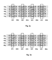
- Figure 2a shows in more detail how these pilot sequences in this example are transported over the lines 103 1 to 103 n over time.
- the DSLAM 101 is not interested in obtaining information about lines 103 4 and 103 5 , and so transmits constant sync sequences on these lines.
- Figure 2a shows the symbols transported over the communication lines 103 1 to 103 5 in a certain time period. During this time period, a number of sync symbols and a number of data symbols are transmitted over the line from DSLAM 101 to the respective CPE 102 1 to 102 5 .
- the line transports a data symbol, thus this figure does not necessarily start with a silent line or a line whereon no data is transported.
- the sync symbol is the first signal transmitted over that line.
- the sync symbols on each of the lines are transmitted simultaneously.
- the first symbol of each pilot sequence is transmitted on each line simultaneously, then after a data symbol the second symbol of each pilot sequence is transmitted, and so on.
- the DSLAM 101 is interested in obtaining information about the crosstalk channels from the lines 103 1 to 103 3 onto all other lines in the precoding group.
- the DSLAM 101 of the precoding group monitors the error feedback from every line 103 1 to 103 n and combines the pilot sequences with the error feedback to obtain the crosstalk information via a correlation.
- the DSLAM 101 also monitors the error feedback information from the lines 103 1 to 103 3 which make up the subset and whereon the pilot sequences are transmitted. If any legacy lines are present in the precoding group, the DSLAM 101 will not receive error feedback from those lines.
- Figure 2b shows a second example wherein both the vector-enabled lines 103 1 to 103 3 and legacy lines 103 4 and 103 5 are present. Similar to figure 2a, figure 2b illustrates the transmitted symbols over time. During the first two sync symbols, the DSLAM 101 is interested in obtaining information about the crosstalk channels from legacy line 103 4 . To get this information, the DSLAM 101 uses an induced sync symbol to transmit the pilot sequence [1, -1] on line 103 4 , and transmits a constant sequence on all other lines.
- the DSLAM correlates the error feedback received from vector enabled lines 103 1 to 103 3 during the first and second sync symbols with the pilot sequence [1,-1] to obtain estimates of crosstalk coefficients from line 103 4 into lines 103 1 to 103 3 .
- the DSLAM 101 is interested in obtaining information about the crosstalk channels from line 103 5 .
- the DSLAM 101 uses an induced sync symbol to transmit the pilot sequence [-1, 1] on line 103 5 , and transmits a constant sequence on all other lines.
- the DSLAM correlates the error feedback received from lines 103 1 to 103 3 during the third and fourth sync symbols with the pilot sequence [-1, 1] to obtain estimates of crosstalk coefficients from line 103 5 into lines 103 1 to 103 3 . Because only one line is included in the subset of interest at a given time, each of the legacy lines is only required to use one induced sync flag in this example.
- Figure 1 shows a total of six communication lines connected to the DSLAM.
- a DSLAM is typically connected to a larger number of lines than six.
- a precoding group may not be limited to the lines connected to a single DSLAM.
- a precoding group may for instance contain several tens of lines which are distributed over a number of DSLAMs. In such case, coordination between DSLAMs may be required.
- Figure 1 furthermore only shows the elements in the communication network which are relevant for the understanding of the present invention. Therefore elements such as network equipment to which the DSLAM is connected, links connecting the DSLAM to such equipment, intermediary devices, etc. are not shown in this figure. It should be appreciated by those skilled in the art that a real world scenario typically contains a much more complex network topology than shown in this figure.
- figures 2a and 2b only represent an example of pilot sequences and how information is transmitted over a particular set of lines. It is obvious that other combinations of pilot sequences and line selections are also possible.
Abstract
Description
- The present invention generally relates to precoding on communication lines and in particular to a device and method for estimating crosstalk information which can be used in precoding on communication lines such as very high speed digital subscriber lines (VDSL) and VDSL2 lines.
- Various communication lines which operate within each others' vicinity may induce signals on each other. For instance two communication lines such as two VDSL2 lines which are collocated next to each other induce a signal in each other. Such signal is called crosstalk and has an influence on the quality of communication on these lines. Due to the induced crosstalk and noise from other sources in the surroundings of the communication line, the data transported on these lines may be affected or corrupted by the crosstalk and noise. Corrupted data needs to be corrected or transmitted again before the receiver can process the data. By reducing the crosstalk induced on a communication line or compensating the crosstalk induced on a communication line, the amount of corrupted data may be reduced ,the need for error corrections or retransmissions is reduced, and the rate at which information can be reliably communicated is increased.
- Various prior art solutions exist which are able to reduce the effects of crosstalk on communication lines and in particular on digital subscriber lines. These solutions are typically based on performing measurements on communication lines and adapting the operational conditions of the lines accordingly. Such measurements provide information concerning the crosstalk between various communication lines which can be used as an indication for line quality, attainable data rate, reliability of the communication channel, etc. The crosstalk channel coefficients can be used to reduce the effects of crosstalk on the communication line or to compensate for the crosstalk in order to remove the problem almost entirely.
- Each communication line is a possible disturber line which induces crosstalk in one or more victim lines. By transmitting test signals across all the lines, it is possible to determine the influence of each offender line on the victim lines. The test signals can be characterized by the way in which power is allocated to one or more tones or frequencies. For instance a test signal may be transmitted using a particular power level over a small frequency range. The victim line may notice this power in that frequency range and be able to determine the amplitude of that power. The amplitude of the induced influence of crosstalk on a particular line is a good reference to determine how strong particular crosstalkers are or which frequencies or tones are susceptible to the crosstalk of certain crosstalkers. In particular, if each possible communication line which may induce crosstalk (also called a crosstalker) emits a distinct power spectrum as test signal, it is possible to detect which crosstalker or crosstalkers are inducing noise on a given victim line.
- The information obtained by such measurements can then be used to group communication lines in physical groups or logical groups or binders, define the transmit spectra on the communication lines, etc. This enables a network operator to configure lines in such a way that crosstalk is avoided as much as possible or that the effects of crosstalk are reduced. For instance by selecting a transmit spectrum on a victim line in such a way that frequencies or tones with strong crosstalk influences from offender lines are avoided, the quality of the victim line is improved and the crosstalk is reduced.
- A problem with the above given approach is that it is difficult to adjust transmit power spectra of lines in operation. Such changes reduce the throughput of the line significantly and may even lead to a service outage for a user when a line has to be reconfigured. Thus the above described technique can only be used for upcoming lines which may also be called joining lines and may not be able to handle significant changes in crosstalk once the line is in operation. In addition, the measurements can be performed relatively easily by transmitting a particular power on the possible disturber lines. However by altering the transmit power or power spectral density (PSD), it is only possible to measure or estimate the amplitude of the crosstalk. The phase of the crosstalk signal cannot be assessed using such a technique. This means that the exact crosstalk channel, described mathematically by complex coefficients having both magnitude and phase, is not known.
- Precoding techniques are based on transmitting an additional signal on top of the data signal which is used to compensate the crosstalk on a victim line from external sources. Thus, instead of reducing the effect of crosstalk or avoiding crosstalk effects by configuring the communication line in an appropriate way, precoding can be used to compensate for the effects of crosstalk on a communication channel. Precoding techniques are based on crosstalk channel information that includes both amplitude and phase information. Such information can be obtained from measurements such as slicer error or SNR. A particular example of such measurements for precoding is the use of pilot sequences and error feedback. The use of pilot sequences in G.vdsl2 or g.vector is described in contributions to ITU study group 15 question 4/15 such as those from Upzide Labs titled "G.vdsl2 pilot sequence assisted vector channel estimation" (C-0177, Geneva, October 2006) and Ikanos Communications titled "G.vdsl crosstalk channel estimation with improved convergence" (NC-082, Napa Valley, April 2007). The term error feedback, as used in this document, refers to a means by which the receiver of a communication system such as a CPE communicates to the transmitter of the communication system such as a DSLAM one or more received signal errors, or values derived from received signal errors. Received signal errors can be defined as the difference between the received signal and an estimate of the transmitted signal.
- These papers describe the use of a particular pilot sequence on each communication line in order to estimate the crosstalk channels between the communication lines. For those skilled in the art it is clear that according to these papers, it is possible to use orthogonal pilot sequences for each of the communication lines in a precoding group. Thus, on each communication line a pilot sequence is transmitted which may influence other communication lines in the precoding group.
- A pilot sequence, in particular in DSL technology, is a series of pilot signals which are transmitted for instance downstream from the Digital Subscriber Line Access Multiplexer (DSLAM) to the Customer Premises Equipment (CPE) and can for instance be described as a sequence of constellation points in a 4-QAM constellation. On a communication line, all active sub-carriers are modulated by two bits, either both zero (00) or both one (11), from the sync-frame using 4-QAM. The constellation points are rotated using a quadrant scrambler and due to the operation of the scrambler, it only has to be taken into account when crosstalk coefficients are determined. The constellation points 00 or 11 are transmitted downstream during a sync symbol on the communication line. Such sync symbols are periodically transmitted, typically after every 256 data symbols. The constellation points 00 and 11 have a complex representation being "+1 + j" for 00 and "-1 - j" for 11. For simplicity throughout this text, the constellation point 00 will be represented as '1' and the constellation point 11 will be represented as '-1'.
- A pilot sequence is a series of such constellation points, each transmitted in a separate sync symbol. For instance, a pilot sequence may consist of a sequence of 1 and -1 which is transmitted over the communication line, each sync symbol containing one of the points in the sequence. Since these points are defined and thus known to the receiver, it is possible to determine the difference between the expected symbol and the actual received symbol. This difference, which includes interference and noise can then be fed back to the DSLAM. The DSLAM is then able to correlate the error feedback and the pilot sequence in order to obtain the amplitude and phase of the crosstalk from one line to another line.
- A first drawback of the existing solution is that the estimation requires a long period of time when the number of communication lines in the precoding group is high. Large precoding groups also require a large amount of processing power and storage to store and process all the error feedback information and to combine transmitted pilot sequences with the error feedback to obtain an estimation of the crosstalk.
- A second drawback is found in a scenario where there are strong and weak crosstalkers in a precoding group. Some offender lines affect victim lines significantly more strongly than other offender lines. The influence of the weaker crosstalkers may therefore be irrelevant as their influence is negligible compared to that of the strong crosstalkers. The existing solutions devote equal time and computation to determining strong and weak crosstalkers and generally provide a complete estimation of all the crosstalk coefficients, which may be a waste of computational power and time because information from the strong crosstalkers alone may be sufficient to perform precoding in the precoding group.
- A third drawback is that when a joining communication line is initialized, crosstalk estimates are required for that communication line and in particular the influence of that line on other lines in the precoding group is of importance. However the existing solutions are only able to estimate crosstalk for the entire group which means that when a line joins, it may take some time before sufficient information is available to configure the line and to perform accurate precoding.
- When considering DSL lines, precoding is a new technique which is introduced to VDSL2 in the G.Vector extension thereof. However not all equipment supports the G.Vector specifications and thus not all communication lines are vector-enabled lines. Communication lines which only support the VDSL2 standard specification are called legacy lines. The sync symbols are defined in the VDSL2 standard specification for legacy lines. This means that transmitting a pilot sequence on a legacy line may conflict with the standard specification. Furthermore, legacy lines are generally unable to communicate errors measured on the sync symbols to the DSLAM.. As a result, the existing systems have difficulties in obtaining crosstalk information in a precoding group which consists of both legacy lines and vector-enabled lines.
- In
WO2008/02496 - Also document "G. vdsl: Update of the channel estimation matrix during the insertion of a new user" (France Telecom, ITU-T Study Group 15 - contribution 511; COM 15 - C 511 - E, May 2007 (2007-05)) is concerned with adaptations required when a new user joins a coordinated transmission.
- It is an objective of the present invention to provide a device for estimating crosstalk in a precoding group which is able to estimate crosstalk with reduced computational power. It is another objective of the present invention to improve crosstalk estimation in a precoding group with legacy lines and vector-enabled lines. It is yet another objective of the present invention to obtain information on lines of interest. It is another objective of the present invention to reduce the per-estimate delay.
- The objectives of the present invention are realized by a crosstalk estimation device for estimating crosstalk between communication lines in a precoding group comprising:
- transmission means for transmitting a pilot sequence;
- reception means for receiving error feedback on one or more communication lines in the precoding group; and
- crosstalk estimation means for combining the pilot sequence with the error feedback in order to obtain a crosstalk estimation between the communication lines,
- Optionally the crosstalk estimation device according to the present invention may further comprise means for selecting said pilot sequence based on the number of communication lines in the subset.
- Indeed, by selecting a subset of communication lines from the precoding group and transmitting the pilot sequences only on the communication lines in the subset, it is possible to determine the crosstalk effects of the lines in the subset on other lines in the precoding group which may or may not be part of the subset.
- The present invention is based on the insight that the length of a pilot sequence (L) depends on the number of communication lines whereon a pilot sequence is transmitted (M) to determine crosstalk coefficients. When the sequences are chosen, it is preferred to do so under the constraint that every pair of sequences should be mutually orthogonal. As a result of that constraint, the minimum length of the pilot sequence L equals the number of lines M. However the use of constant sequences should be avoided to reduce a contamination from noise or interference which has a non-zero mean, the constant sequences. In order to have sufficient combinations and especially when orthogonal sequences are desired, in combination with the desire to avoid the use of a constant sequence, the length of the pilot sequence is taken as L ≥ M + 1.
- The relation between the length of the pilot sequence and the number of lines which are currently examined has as a consequence that for large precoding groups, the pilot sequence has a large length. For instance if a precoding group consists of 50 lines, the pilot sequences must be at least 51 symbols long. Thus the prior art solutions would need to wait until those 51 symbols have been transmitted and error feedback of a 51 symbols has been received by the transmitter. In addition to the delay of transmitting those symbols and receiving the error feedback for all those symbols, this also requires a significant amount of storage and processing power. Error feedback on each symbol is received from each line, thus 50 lines have to provide error feedback information on 51 symbols.
- The selection of the subset with K lines reduces the number of M lines whereon a pilot sequence is transmitted. When a subset of for instance K = 5 lines is selected out of M = 50 lines, the pilot sequences are of length L = K + 1 = 6. This means that only 6 sync-symbols are required to transmit an entire pilot sequence which is much shorter than when all the lines are tested simultaneously. In addition to a reduction in delay between starting the transmission of the pilot sequence and obtaining all the error feedback information, the computational power and storage requirements are reduced over the prior art sequences. In case a precoding group consists of 50 lines and a subset is 5 lines, the system still needs to obtain information from those 50 lines. However, each of these lines only has to provide error feedback over 6 symbols instead of 51 which is a large reduction. A feedback subset may be selected from the precoding group, as an alternative to obtaining error feedback from all lines in the precoding group. The feedback subset may overlap with the subset selected for transporting the pilot sequences or may consist of lines whereon no typical pilot sequence is transmitted. Having two subsets, one of lines whereon the pilot sequences are transmitted and one whereon error feedback is collected may reduce the required processing and storage even more. In such scenario, both the length of the pilot sequences is reduced and the number of lines which provide feedback.
- An important advantage of the present invention can be found in scenarios where a particular joining line in the precoding group changes from an inactive line to an active line. Joining lines introduce new crosstalk on active lines which means that their influence on the other lines has to be determined and eliminated by precoding before the joining line begins normal full-power transmission. Otherwise, the joining line may interrupt active lines or reduce the signal quality of active lines significantly. It is therefore beneficial to find ways to estimate crosstalk from a joining line quickly, so that the joining line can quickly begin normal full-power transmission without harming other lines. To obtain the shortest delay, it is beneficial to select a subset of K = 1 line where that single line is the joining line. For a subset of K = 1, the pilot sequence is of length L = 2 which means that the delay to estimate the crosstalk of that particular joining line on other lines is reduced to the transmission of only two symbols. Even if all lines in the precoding group are taken into consideration when determining the crosstalk information, thus feedback information is received and used from each line in the precoding group except the joining line which is transporting the pilot sequences, this reduces the computational requirements and time required for the computation of crosstalk information significantly. This means that repeated measurements, each consisting of error feedback from L = 2 symbols, can be performed on the joining line during initialization. Repeated measurements in a smaller time-frame have as a result that the power at which the joining line is allowed to operate can increase at a higher rate than in a situation where longer sequences are used, for example as would be necessary if unique orthogonal pilot sequences are sent on all communication lines.
- The error feedback measurement on lines may be something which is performed automatically or which may be coordinated. In certain embodiments, a receiver such as a CPE may always perform measurements on received signals and provide error feedback to a transmitter such as a DSLAM based on those measurements. The receiver or CPE may perform those measurements on every signal or on particular signals or symbols. However a transmitter or DSLAM may instruct the receiver or CPE to perform error measurements on a certain signal or symbol for a particular period of time or number of symbols or until the DSLAM instructs the receiver or CPE to stop measurements. In case of measurements which are performed continuously on particular symbols and error being fed back as soon as the measurement has ended, a DSLAM is able to determine crosstalk information by simply initiating the transmission of pilot sequences as the error feedback will be available anyway. Due to the potential high number of CPE's or receivers connected to a DSLAM or transmitter, sending instructions to each CPE may introduce a large load on the DSLAM to coordinate the instructions and introduces additional load on the communication lines whereon the instructions are transmitted. The error feedback information may be transmitted back as soon as it is available or may be collected at the CPE side until all measurements are performed. The advantage of feedback as soon as available is that each error feedback communication requires a small piece of the available bandwidth on the communication line whereas sending all the data back in a single transmission may require a higher peak bandwidth. The DSLAM may be able to request the error feedback information from the CPE or the CPE may deliver the information to the DSLAM automatically.
- It is important to realize that in view of the present Invention, signals which are transported on communication lines which are not part of the subset are not considered pilot sequences. Communication lines which are not part of the selected subset typically will also transport a particular signal while the lines in the subset transport their pilot sequence. For instance where pilot sequences are transported in the sync symbol on each line, the lines of the precoding group not part of the subset may transport a symbol in their sync symbol. Of course, care should be taken to ensure that the signals transported in the sync symbol on lines not in the subset are distinguishable from those used in the pilot sequences. When pilot sequences are equal to or are strongly correlated with the signals transported in the sync symbols of lines not in the subset, it is difficult or impossible to accurately estimate crosstalk coefficients from lines in the subset, using error feedback. On the other hand, when pilot sequences are orthogonal to the signals transported in the sync symbols of lines not in the subset, these latter signals do not interfere at all with the ability to estimate crosstalk coefficients from lines in the subset, using error feedback.
- Optionally the crosstalk estimation device according to the present invention may further comprise means for estimating crosstalk based on a correlation between the error feedback and the pilot sequence.
- The device which transmits the pilot sequences such as a DSLAM is aware of the transmitted pilot sequences. By receiving the error feedback information from the device which receives the pilot sequences such as a CPE, the device is able to determine the crosstalk coefficients of the crosstalk channels between the lines whereon pilot sequences are transmitted and the lines wherefrom error feedback information is used. The crosstalk coefficients can be determined based on a correlation between the transmitted pilot sequence and the received error feedback. The correlation ensures that an exact estimation of the crosstalk coefficients is obtained and that the crosstalk channels are characterized accurately. Such accurate information can then be used to adapt the precoding in order to substantially eliminate interference from existing crosstalk channels.
- Optionally the transmission means of the crosstalk estimation device according to the present invention may be adapted for transmitting a distinct pilot sequence on each of the communication lines in the subset.
- Further optionally, the pilot sequence may be a non-constant sequence.
- The use of error feedback information is sufficient to determine the crosstalk channels that Influence a given communication line. It is therefore possible to transmit a pilot sequence on each line in the subset and use the same sequence on all the communication lines in the set simultaneously. The disadvantage of this technique is however that it is impossible to uniquely identify the influence of a particular line in the subset on other lines in the precoding group.
- By using distinct pilot sequences on the communication lines in the subset, it is possible to determine the exact crosstalk channel coefficients between the line which transports a particular pilot sequence and every line in the precoding group from which error feedback information is gathered. Having distinct pilot sequences for each communication line ensures that each existing crosstalk channel is known rather than a general idea of the overall crosstalk effects on a particular line.
- Distinct pilot sequences are pilot sequences such that no two pilot sequences are identical. In addition, it is beneficial to choose pilot sequences that are mutually orthogonal, meaning that the correlation between each pair of sequences is zero. In addition, it is beneficial to ensure that the pilot sequences are also orthogonal to any normal transmissions on other communication lines which are not in the subset in the symbols wherein the pilot sequences are transmitted. The sequences are preferably made up out of 1 or -1 and frequent changes are preferred. Signals which are generally constant, for instance sequences with only one change from 1 to -1 or vice versa) may resemble control signals on communication lines and may therefore lead to problems and should be avoided.
- Optionally the transmission means of the crosstalk estimation device according to the present invention may be adapted to transmit the pilot sequence in one or more sync symbols.
- Further optionally the crosstalk estimation device according to the present invention may further comprise means for inducing an additional sync-flag into the communication lines.
- The G.Vector community considers transmitting the pilot sequences on the sync symbol which is transmitted via a communication line. Legacy lines use the sync symbol to transport sync-flags from transmitter (such as a DSLAM) to receiver (such as CPE). For instance when On-Line Reconfiguration requests are transmitted from the CPE to the DSLAM, the DSLAM acknowledges the receipt of the OLR request by sending a sync-flag. A sync-flag is typically a change in the sign in the sync symbol, either from 1 to -1 or from -1 to 1 whereas otherwise this symbol is constant. However for vector-enabled lines the use of the sync symbols is not defined in a standard specification and thus these symbols could be used for other purposes such as transmitting pilot sequences.
- Because legacy lines do not provide the functionality to measure error signals on the sync symbols and to provide error feedback to the transmitter or DSLAM, it is not possible to use the error feedback method to determine the crosstalk induced on these lines by other lines. However by inducing additional sync-flags, it is possible to effectively transmit a pilot sequence over legacy lines. Thus by providing means for inducing sync-flags, it is possible to determine the crosstalk induced by a legacy line on a communication line operating according to the G.Vector specifications also called a vector enabled line. Vector enabled lines are able to determine error information on received sync symbols and are able to feed back such error information to the transmitter.
- Sync-symbols sent from the DSLAM at the CO to the CPE over a legacy line are interpreted by the CPE according to the standard specification. Thus any sync-symbol which is sent as part of a pilot sequence is interpreted in a standardised way by the CPE. To overcome this problem, the DSLAM may induce additional sync-flags on the line which can then be used as elements of a pilot sequence. A first way of inducing a sync-flag which can be used as part of a pilot sequence is by reducing the power from the DSLAM side on one or more tones. By reducing the power on a small number of tones, the effect of the power reduction is negligible but a bitswap is called for. As a consequence of the power reduction, the CPE will request a bit swap. Such a request has to be acknowledged by the DSLAM via a sync-flag sent to the CPE. This sync-flag could be used as an element in the pilot sequence. Alternatively the DSLAM could just transmit an unexpected sync-flag to the CPE. If the CPE does not expect such a sync-flag, for instance because no OLR request was made, it may discard the sync-flag. These two forms of inducing can be used to transmit the pilot sequence and thus provide information on the crosstalk influence from a legacy line on a vector enabled line. However this also means an overloading of the sync-symbols and additional load on the CPE and the control channel. It may therefore be beneficial to limit the use of induced sync-flags where possible. It can be beneficial to use small subsets and short sequences when estimating crosstalk from legacy lines, because the legacy lines are only required to send induced sync-flags when they belong to the subset, and they do not need to send induced sync-flags when they do not belong to the subset.
- The technique of inducing sync-flags is advantageous in that it enables the transmission of pilot sequences over legacy lines. This means that in a precoding group crosstalk information is available from vector-enabled lines to vector-enabled lines and from legacy lines to vector-enabled lines. As a consequence, complete crosstalk information is available for the vector-enabled lines which allows the use of precoding on all the vector-enabled lines in the precoding group.
- Optionally the crosstalk estimation device according to the present invention may further comprise means for selecting a tone subset of one or more tones for each communication line in the subset of communication lines and means for transmitting the pilot sequence only in the tone subset.
- Further optionally the crosstalk estimation device according to the present invention may further comprise means for interpolating error feedback information and/or crosstalk coefficient estimates for tones not in the tone subset.
- It is typically envisioned that when the communication lines are based on a discrete multi-tone (DMT) system, the same element of the pilot sequence assigned to that communication line would be sent on each tone during the sync symbol. For example, if the assigned pilot sequence for a communication line in the subset was [1,1,-1,-1], the transmitter would send a "1" on all tones, then later send the value "1" on all tones, then send "-1" on all tones and finally send "-1" on all tones. Typically in the G.Vector case this 1 or -1 would be sent during a sync symbol which alternates with data symbols being transmitted on the line.
- As discussed above, a general scheme for creating pilot sequences for such a system works as follows. There are M lines and a subset of K lines is selected for estimation. K pilot sequences, preferably mutually orthogonal pilot sequences, of length L ≥ K+1 are selected (using, for example, Walsh-Hadamard sequences). With these parameters, the estimation procedure takes a set of pilot sequences of length L to obtain an estimate for K lines.
- It is however possible to achieve a more favorable trade-off by estimating the crosstalk coefficients on a subset of tones and preferably obtaining the rest of the coefficients by interpolation. This takes advantage of the smoothness in the crosstalk coefficients as a function of tone index. Assuming that the crosstalk channels are appropriately smooth, this allows one to reduce the time and/or complexity required to achieve a given accuracy.
- We introduce a new parameter W, which represents the spacing between the tones selected for the tone subset. That is, if W = 1, all tones will be estimated and thus the elements of the pilot sequence will be transmitted on all tones on the communication line. If W = 4, one will directly estimate the crosstalk only on one out of every four tones and thus the elements of the pilot sequence will be transmitted on every fourth tone on the communication line. We still have M lines, and we choose K (preferably mutually orthogonal) pilot sequences of length L ≥ K +1 in order to be able to target K lines on a given tone at one time. An advantage is that when each of the K pilot sequences is assigned to W different lines, N = KW lines have sequences assigned in any one iteration. Thus, the same pilot sequence can be used to estimate crosstalk channel coefficients of W lines by using different tones to transport the pilot sequence on each communication line. The crosstalk channel coefficients of a subset of N lines in a precoding group can therefore be estimated using only N/W distinct pilot sequences.
- A particular example of how a pilot sequence can be arranged on the tones is given below. However it should be noted that the person skilled in the art may consider other ways of arranging the pilot sequences on the tones. The first of the W lines sharing a pilot sequence transmits the pilot sequence on tones with index k such that k mod W =1. The second line transmits the pilot sequence on tones such that k mod W = 2, and so on. In other words, the first tone transports the first element of the pilot sequence on a first line, the second tone transports the first element of the pilot sequence on a second line, etc. After W tones, the second element of the pilot sequence is transmitted on the first line in tone W+1, the second element of the pilot sequence is transmitted on the second line in tone W+2, etc. All other tones being the tones not in the tone subset transmit a sequence which is not used for crosstalk channel estimation and is generally a constant sequence. For example, on the first line, tones 2 through W, W + 2 through 2W, and so on transmit a constant sequence. Finally, all lines that are not part of the subset in a given iteration transmit a sequence which is not used for crosstalk estimation and is generally a constant sequence on all tones.
- After the sequences of length L have been sent, the system can directly estimate the crosstalk coefficients on all the tones in the tone subset on the lines in the subset of communication lines. On a given line in the subset, there will be estimates for one out of every W tones. The coefficients for the remaining tones on that line can be estimated by interpolation between the directly estimated coefficients.
- With these parameters, the estimation procedure takes time L to obtain estimates for WK lines, with computational and storage complexity proportional to MK. The variance of the estimate is proportional to 1/L, and the total time required to get estimates for all lines is ML/(WK).
- The benefit of the invention is to increase by a factor of W > 1 the number of lines whose crosstalk coefficients can be simultaneously estimated, with a similar complexity. This reduces the amount of time required to estimate all lines by a factor of W. The maximum value of W that can be used is determined by the smoothness of the crosstalk channels as a function of frequency.
- Optionally the selection means of the crosstalk estimation device according to the present invention may be adapted to select the subset based on one or more of the following:
- an indication of an upcoming communication line in the precoding group;
- an indication of legacy or vector-enabled communication lines in the precoding group;
- awareness of strong crosstalkers in the precoding group;
- evolution of crosstalk in the precoding group over time; and
- knowledge of corrupted or missing error feedback measurements.
- Information such as indications or identifications of an upcoming communication line in the precoding group may be used to determine which lines will form part of the subset. For instance any upcoming or joining communication line may be a trigger to perform crosstalk estimation on a subset of one line being the joining line. This way the available crosstalk channel coefficients can be updated accordingly to incorporate the new line and the changes in crosstalk.
- In certain situations it may be desired to only include a certain type of lines in the subset. Legacy lines are only able to transport pilot sequences under certain conditions and cannot provide error feedback. It may therefore be preferred to only use the pilot sequences on vector-enabled lines. Selecting only vector-enabled or legacy lines may also determine how the pilot sequences are transmitted. For instance if there are no legacy lines in the subset, the transmitting device may disable means to induce sync-flags. As another example, the transmitting device may use small subsets and short sequences when estimating crosstalk from legacy lines, and larger subsets and longer sequences when estimating crosstalk from vector enabled lines.
- When a certain precoding group contains a number of strong crosstalkers, it may be beneficial to take these known strong disturber lines in a subset. Generally the crosstalk information obtained from strong crosstalkers will be representative for the major portion of all the crosstalk in the precoding group. Thus, by only determining the crosstalk coefficients for the crosstalk channels related to the strong crosstalkers, a good estimation of the overall crosstalk can be made and resources can be saved when compared to determining all crosstalk channels in the precoding group. In addition, crosstalk induced by a given communication line may change over time. Such information may be taken into account when selecting a subset. For instance, when the changes in crosstalk are beyond certain thresholds, the system may reevaluate more often the crosstalk channels related to that specific line whereon the crosstalk has changed. This way the information can be kept up-to-date without measuring crosstalk channels for all lines in the precoding group.
- In some cases, error measurements at the CPE may be corrupted by impulse noise, or error measurements sent from the CPE to the CO may not be received correctly. In this case, the available error measurements may be sufficient to estimate certain crosstalk coefficients accurately, and not sufficient to estimate other coefficients. In such a case, the subset could be chosen to include lines whose crosstalk coefficients are still unknown due to the lost or corrupted error measurements.
- Optionally the communication lines in said precoding group and the communication lines in said subset are digital subscriber lines.
- Further optionally the crosstalk estimation device according to the present invention may be integrated into a digital subscriber line access multiplexer and/or a network analyzer.
- Network equipment such as a DSLAM or other access multiplexer, network analyzer, etc are ideally suited to keep track of crosstalk channel coefficients. Access multiplexers are directly involved in the communication lines whereon data is transported and for which the crosstalk channel coefficients are determined. An access multiplexer is coupled to these communication lines and transmits and receives information over the communication lines. The DSLAM can therefore control the transmissions by having a crosstalk estimation device according to the present invention integrated. Similarly, a network analyzer may be able to keep track of all the crosstalk channels in the network and may be able to instruct access multiplexers to perform certain crosstalk channel estimations.
- Optionally In the crosstalk estimation device according to the present invention, the number of communication lines in the subset is at least one and is less than the total number of communication lines in the precoding group.
- In view of the above given explanation related to the length of the pilot sequences being related to the number of lines whereon pilot sequences are transmitted, the crosstalk estimation device may be adapted to select at least one but less than the total number of lines in the precoding group for the subset. Small subsets provide crosstalk channel coefficients at a higher speed than larger subsets, but larger subsets may provide a higher accuracy of the estimations. The ideal size may depend on selection criteria for adding a line to the subset, desired performance in terms of accuracy and delays and other factors such as the number of available communication lines in the precoding group, already available crosstalk information, etc.
- The present invention further also relates to a method for estimating crosstalk between communication lines in a precoding group comprising the steps of:
- transmitting a pilot sequence;
- receiving error feedback on one or more communication lines in the precoding group; and
- combining the pilot sequence with the error feedback in order to obtain a crosstalk estimation between the communication lines,
-
-
Fig. 1 illustrates an overview of a DSLAM wherein an embodiment of the present invention is incorporated which is connected to a number of CPE devices; and -
Fig. 2a and 2b illustrate pilot sequences transmitted on communication lines. -
Figure 1 shows aDSLAM 101 which is connected to a number ofCPE devices 1021 to 102n.CPE 1021 toCPE 102n are connected viarespective VDSL2 lines 1031 to 103n. In this particular example thelines 1031 to 103n all form part of the same precoding group and the precoding group in this example is limited to thelines 1031 to 103n. - In this particular embodiment, the
DSLAM 101 is provided with a crosstalk estimation device according to the present invention.DSLAM 101 is thus able to define pilot sequences, select a subset of lines fromlines 1031 to 103n, transmit a pilot sequence on each of the selected lines in the subset and receive error feedback from theCPE 1021 to 102n. The crosstalk estimation device inDSLAM 101 can then be used to determine the crosstalk channel coefficients which represent the crosstalk channels between the lines in the precoding group. For this example, we considerlines 1031 to 1033 as vector enabled lines andlines - In a first example, the
DSLAM 101 selectslines 1031 to 1033 as subset of the precoding group. The DSLAM generates three orthogonal pilot sequences of length 4, one for each of the lines in the selected subset. The three pilot sequences are [1, 1, -1, -1]. [1. -1, 1, -1] and [1, -1, -1, 1] which are destined forlines 1031 to 1033 respectively.Figure 2a shows in more detail how these pilot sequences in this example are transported over thelines 1031 to 103n over time. In this example, theDSLAM 101 is not interested in obtaining information aboutlines -
Figure 2a shows the symbols transported over thecommunication lines 1031 to 1035 in a certain time period. During this time period, a number of sync symbols and a number of data symbols are transmitted over the line fromDSLAM 101 to therespective CPE 1021 to 1025. It should be noted that before the shown sync symbol, the line transports a data symbol, thus this figure does not necessarily start with a silent line or a line whereon no data is transported. It is however not excluded that on one or more of the shown lines, the sync symbol is the first signal transmitted over that line. The sync symbols on each of the lines are transmitted simultaneously. The first symbol of each pilot sequence is transmitted on each line simultaneously, then after a data symbol the second symbol of each pilot sequence is transmitted, and so on. - In this first example, it is assumed that the
DSLAM 101 is interested in obtaining information about the crosstalk channels from thelines 1031 to 1033 onto all other lines in the precoding group. TheDSLAM 101 of the precoding group monitors the error feedback from everyline 1031 to 103n and combines the pilot sequences with the error feedback to obtain the crosstalk information via a correlation. TheDSLAM 101 also monitors the error feedback information from thelines 1031 to 1033 which make up the subset and whereon the pilot sequences are transmitted. If any legacy lines are present in the precoding group, theDSLAM 101 will not receive error feedback from those lines. -
Figure 2b shows a second example wherein both the vector-enabledlines 1031 to 1033 andlegacy lines figure 2a, figure 2b illustrates the transmitted symbols over time. During the first two sync symbols, theDSLAM 101 is interested in obtaining information about the crosstalk channels fromlegacy line 1034. To get this information, theDSLAM 101 uses an induced sync symbol to transmit the pilot sequence [1, -1] online 1034, and transmits a constant sequence on all other lines. The DSLAM correlates the error feedback received from vector enabledlines 1031 to 1033 during the first and second sync symbols with the pilot sequence [1,-1] to obtain estimates of crosstalk coefficients fromline 1034 intolines 1031 to 1033. Similarly, during the third and fourth sync symbols, theDSLAM 101 is interested in obtaining information about the crosstalk channels fromline 1035. To get this information, theDSLAM 101 uses an induced sync symbol to transmit the pilot sequence [-1, 1] online 1035, and transmits a constant sequence on all other lines. The DSLAM correlates the error feedback received fromlines 1031 to 1033 during the third and fourth sync symbols with the pilot sequence [-1, 1] to obtain estimates of crosstalk coefficients fromline 1035 intolines 1031 to 1033. Because only one line is included in the subset of interest at a given time, each of the legacy lines is only required to use one induced sync flag in this example. -
Figure 1 shows a total of six communication lines connected to the DSLAM. However in a real world scenario, a DSLAM is typically connected to a larger number of lines than six. In addition, a precoding group may not be limited to the lines connected to a single DSLAM. A precoding group may for instance contain several tens of lines which are distributed over a number of DSLAMs. In such case, coordination between DSLAMs may be required.Figure 1 furthermore only shows the elements in the communication network which are relevant for the understanding of the present invention. Therefore elements such as network equipment to which the DSLAM is connected, links connecting the DSLAM to such equipment, intermediary devices, etc. are not shown in this figure. It should be appreciated by those skilled in the art that a real world scenario typically contains a much more complex network topology than shown in this figure. - In addition,
figures 2a and 2b only represent an example of pilot sequences and how information is transmitted over a particular set of lines. It is obvious that other combinations of pilot sequences and line selections are also possible. - Although the present invention has been illustrated by reference to specific embodiments, it will be apparent to those skilled in the art that the invention is not limited to the details of the foregoing illustrative embodiments, and that the present invention may be embodied with various changes and modifications without departing from the scope thereof. The present embodiments are therefore to be considered in all respects as illustrative and not restrictive, the scope of the invention being indicated by the appended claims rather than by the foregoing description, and all changes which come within the meaning and range of equivalency of the claims are therefore intended to be embraced therein. In other words, it is contemplated to cover any and all modifications, variations or equivalents that fall within the scope of the basic underlying principles and whose essential attributes are claimed in this patent application. It will furthermore be understood by the reader of this patent application that the words "comprising" or "comprise" do not exclude other elements or steps, that the words "a" or "an" do not exclude a plurality, and that a single element, such as a computer system, a processor, or another integrated unit may fulfil the functions of several means recited in the claims. Any reference signs in the claims shall not be construed as limiting the respective claims concerned. The terms "first', "second", third" and the like, when used in the description or in the claims are introduced to distinguish between similar elements or steps and are not necessarily describing a sequential or chronological order. It is to be understood that the terms so used are interchangeable under appropriate circumstances and embodiments of the invention are capable of operating according to the present invention in other sequences, or in orientations different from the one(s) described or illustrated above.
Claims (13)
- A crosstalk estimation device for estimating crosstalk between communication lines in a precoding group comprising:- transmission means for transmitting a pilot sequence;- reception means for receiving error feedback on one or more communication lines in said precoding group; and- crosstalk estimation means for combining said pilot sequence with said error feedback in order to obtain a crosstalk estimation between said communication lines,
said device further comprising selection means for selecting a subset of one or more communication lines from said precoding group, and whereby said transmission means are adapted to transmit said pilot sequence only on said subset, characterized in that said crosstalk estimation device further comprises means for selecting pilot sequences based on the number of communication lines in the subset. - The crosstalk estimation device as defined in claim 1,
characterized in that said crosstalk estimation device further comprises means for estimating crosstalk based on a correlation between said error feedback and said pilot sequence. - The crosstalk estimation device as defined in claim 1,
characterized in that said transmission means are adapted for transmitting a distinct pilot sequence on each of said communication lines in said subset. - The crosstalk estimation device as defined in claim 1,
characterized in that said pilot sequence is a non-constant sequence. - The crosstalk estimation device as defined in claim 1,
characterized in that said transmission means are adapted to transmit said pilot sequence in one or more sync symbols. - The crosstalk estimation device as defined in claim 1,
characterized in that said device further comprises means for inducing an additional sync-flag into said communication lines. - The crosstalk estimation device as defined in claim 1,
characterized in that said device further comprises means for selecting a tone subset of one or more tones for each communication line in said subset of communication lines and means for transmitting said pilot sequence only in said tone subset. - The crosstalk estimation device as defined in claim 78,
characterized in that said device further comprises means for interpolating error feedback information or crosstalk coefficient estimates for tones not in said tone subset. - The crosstalk estimation device as defined in claim 1,
characterized in that said selection means are adapted to select said subset based on one or more of the following:- an indication of an upcoming communication line in said precoding group;- an indication of legacy or vector-enabled communication lines in said precoding group;- awareness of strong crosstalkers in said precoding group;- evolution of crosstalk in said precoding group over time; and- knowledge of corrupted or missing error feedback measurements. - The crosstalk estimation device as defined in claim 1,
characterized in that said communication lines in said precoding group and said communication lines in said subset are digital subscriber lines. - The crosstalk estimation device as defined in claim 10,
characterized in that said device is integrated into a digital subscriber line access multiplexer and/or a network analyzer. - The crosstalk estimation device as defined in claim 1,
characterized in that the number of communication lines in said subset is at least one and is less than the total number of communication lines in said precoding group. - A method for estimating crosstalk between communication lines in a precoding group comprising the steps of:- transmitting a pilot sequence;- receiving error feedback on one or more communication lines in said precoding group; and- combining said pilot sequence with said error feedback in order to obtain a crosstalk estimation between said communication lines,- selecting a subset of one or more communication lines from said precoding group, whereby said step of transmitting a pilot sequence is adapted to transmit said pilot sequence only on said subset,
characterised by selecting said pilot sequence based on the number of communication lines in the subset.
Priority Applications (6)
| Application Number | Priority Date | Filing Date | Title |
|---|---|---|---|
| EP08290565A EP2136477B1 (en) | 2008-06-16 | 2008-06-16 | Device and associated method for crosstalk estimation |
| AT08290565T ATE519281T1 (en) | 2008-06-16 | 2008-06-16 | APPARATUS AND ASSOCIATED METHOD FOR CROSSTALK ASSESSMENT |
| US12/457,412 US8018868B2 (en) | 2008-06-16 | 2009-06-10 | Device and associated method for crosstalk estimation |
| PCT/EP2009/004226 WO2009152992A1 (en) | 2008-06-16 | 2009-06-12 | Device and associated method for crosstalk estimation |
| KR1020117000889A KR101498005B1 (en) | 2008-06-16 | 2009-06-12 | Device and associated method for crosstalk estimation |
| CN2009101669943A CN101645754B (en) | 2008-06-16 | 2009-06-16 | Device and associated method for crosstalk estimation |
Applications Claiming Priority (1)
| Application Number | Priority Date | Filing Date | Title |
|---|---|---|---|
| EP08290565A EP2136477B1 (en) | 2008-06-16 | 2008-06-16 | Device and associated method for crosstalk estimation |
Publications (2)
| Publication Number | Publication Date |
|---|---|
| EP2136477A1 EP2136477A1 (en) | 2009-12-23 |
| EP2136477B1 true EP2136477B1 (en) | 2011-08-03 |
Family
ID=40019388
Family Applications (1)
| Application Number | Title | Priority Date | Filing Date |
|---|---|---|---|
| EP08290565A Active EP2136477B1 (en) | 2008-06-16 | 2008-06-16 | Device and associated method for crosstalk estimation |
Country Status (6)
| Country | Link |
|---|---|
| US (1) | US8018868B2 (en) |
| EP (1) | EP2136477B1 (en) |
| KR (1) | KR101498005B1 (en) |
| CN (1) | CN101645754B (en) |
| AT (1) | ATE519281T1 (en) |
| WO (1) | WO2009152992A1 (en) |
Families Citing this family (38)
| Publication number | Priority date | Publication date | Assignee | Title |
|---|---|---|---|---|
| WO2009152704A1 (en) | 2008-06-20 | 2009-12-23 | 华为技术有限公司 | Method, equipment and system for channel estimation |
| US7801017B2 (en) * | 2008-08-22 | 2010-09-21 | Alcatel-Lucent Usa Inc. | Communication system for improved cross talk estimation and method thereof |
| US8630383B2 (en) * | 2008-08-22 | 2014-01-14 | Alcatel Lucent | Communication system for transmitting sync-flags and pilot symbols and method thereof |
| US8750492B2 (en) * | 2009-01-30 | 2014-06-10 | Futurewei Technologies, Inc. | Reducing the feedback overhead during crosstalk precoder initialization |
| US8422541B2 (en) * | 2009-05-29 | 2013-04-16 | Alcatel Lucent | Channel estimation in a multi-channel communication system using pilot signals having quasi-orthogonal subpilots |
| CN102082604B (en) * | 2009-12-01 | 2014-01-22 | 富士通株式会社 | Crosstalk factor estimation device and crosstalk factor estimation method |
| US8675469B2 (en) * | 2009-12-17 | 2014-03-18 | At&T Intellectual Property I, Lp | Monitoring non-managed wire pairs to improve dynamic spectrum management performance |
| CN102137314B (en) * | 2010-07-28 | 2015-07-08 | 华为技术有限公司 | Signal transmission method, device and system in digital subscriber line system |
| CN102136852B (en) * | 2010-08-05 | 2014-01-22 | 华为技术有限公司 | Crosstalk counteracting method and system |
| US9667450B2 (en) * | 2010-10-29 | 2017-05-30 | Alcatel Lucent | Detection and correction of impulse noise in communication channel crosstalk estimates |
| EP2664076B1 (en) * | 2011-01-14 | 2017-07-12 | Telefonaktiebolaget LM Ericsson (publ) | Crosstalk limitation between modems |
| CN102111186A (en) * | 2011-02-16 | 2011-06-29 | 华为技术有限公司 | Signal processing method for bound digital subscriber line channels, and device and system adopting same |
| WO2012116147A2 (en) * | 2011-02-23 | 2012-08-30 | Ikanos Technology Ltd. | System and method for partitioning dsl vector cancellation |
| KR101658971B1 (en) * | 2011-04-27 | 2016-09-30 | 이카노스 커뮤니케이션스, 인크. | Systems and methods for G.vector initialization |
| US8917747B2 (en) | 2011-06-11 | 2014-12-23 | Ikanos Communications, Inc. | Method and apparatus for DSL back-channel communication |
| CN102224717B (en) * | 2011-06-16 | 2013-09-11 | 华为技术有限公司 | Activating method for newly adding line pair into xdsl system,apparatus thereof and xdsl system |
| EP2737636B1 (en) * | 2011-07-25 | 2017-01-25 | Telefonaktiebolaget LM Ericsson (publ) | Method for saving power in a telecommunications system |
| EP2573946B1 (en) * | 2011-09-23 | 2014-07-30 | Alcatel Lucent | Power adaptation avoidance during crosstalk measurements |
| CN102388588B (en) * | 2011-09-30 | 2014-04-16 | 华为技术有限公司 | Crosstalk channel estimation method, device and system |
| US9287931B2 (en) * | 2012-03-30 | 2016-03-15 | Broadcom Corporation | Communication system having reduced crosstalk estimation complexity |
| EP2688217B1 (en) | 2012-07-20 | 2015-02-25 | Alcatel Lucent | Method and apparatus for fast and accurate acquisition of crosstalk coefficients |
| CN103828251B (en) | 2012-08-30 | 2016-06-15 | 华为技术有限公司 | A kind of compatible method of VDSL2 legacy user's end equipment, Apparatus and system |
| CN103229445B (en) | 2012-12-26 | 2015-12-02 | 华为技术有限公司 | A kind of initial method of circuit and equipment |
| US9374132B2 (en) * | 2012-12-28 | 2016-06-21 | Broadcom Corporation | Communication system capable of measuring crosstalk in legacy line |
| PL2755333T3 (en) * | 2013-01-11 | 2019-04-30 | Alcatel Lucent | Gain adaptation for downstream vectoring systems |
| JP6405598B2 (en) * | 2013-06-18 | 2018-10-17 | スキピオ テクノロジーズ エス.アイ リミテッド | Robust online reconfiguration (OLR) and synchronization protocol for digital subscriber line (DSL) |
| ES2571430T3 (en) * | 2013-08-06 | 2016-05-25 | Alcatel Lucent | Correspondence cancellation error detection |
| PL2938095T3 (en) | 2014-04-25 | 2017-06-30 | Alcatel Lucent | Full-duplex communication over a shared transmission medium |
| US9258410B2 (en) | 2014-05-30 | 2016-02-09 | Alcatel Lucent | Methods and systems for determining crosstalk for a joining line in a vectored system |
| US10141976B2 (en) | 2015-02-24 | 2018-11-27 | Lantiq Beteiligungs-GmbH & Co. KG | Crosstalk mitigation |
| US20160380673A1 (en) * | 2015-06-23 | 2016-12-29 | Ikanos Communications, Inc. | Vectoring across multiple co boxes/cards/dslams either owned by the same operator or by different operators |
| WO2017008308A1 (en) * | 2015-07-16 | 2017-01-19 | 华为技术有限公司 | Method of increasing transmission rate and device utilizing same |
| CN108028815B (en) * | 2016-01-04 | 2020-09-08 | 华为技术有限公司 | Method for estimating crosstalk channel, vectoring control entity VCE and access node AN |
| US9906308B1 (en) * | 2016-08-23 | 2018-02-27 | Mitsubishi Electric Research Laboratories, Inc. | Methods for compensation of cross-polarization modulation (XPolM) impairments in coherent optical communications |
| CN106407140B (en) * | 2016-09-05 | 2019-06-11 | 华为技术有限公司 | Data processing method and device |
| US10505583B2 (en) | 2016-12-19 | 2019-12-10 | Futurewei Technologies, Inc. | Crosstalk channel estimation for legacy CPE |
| CN109995693A (en) * | 2017-12-31 | 2019-07-09 | 中国移动通信集团四川有限公司 | Offset cable passback crosstalk method, device, equipment and medium |
| CN110752863B (en) * | 2019-10-25 | 2021-07-20 | 中国人民解放军空军工程大学航空机务士官学校 | Method for estimating single-particle crosstalk between multiple lines |
Family Cites Families (11)
| Publication number | Priority date | Publication date | Assignee | Title |
|---|---|---|---|---|
| GB2357937B (en) * | 1999-12-23 | 2003-04-02 | Mitel Corp | DMT bit allocation with imperfect teq |
| ES2188373B1 (en) * | 2001-05-25 | 2004-10-16 | Diseño De Sistemas En Silencio, S.A. | COMMUNICATION OPTIMIZATION PROCEDURE FOR MULTI-USER DIGITAL TRANSMISSION SYSTEM ON ELECTRICAL NETWORK. |
| US7742387B2 (en) * | 2005-04-12 | 2010-06-22 | New Wire Systems, Inc. | Cancellation of crosstalk energy in communication loops |
| WO2008024967A2 (en) | 2006-08-25 | 2008-02-28 | Conexant Systems, Inc. | Systems and methods for mimo precoding in an xdsl system |
| JP2010524399A (en) * | 2007-04-10 | 2010-07-15 | イカノス・コミュニケーションズ・インコーポレーテッド | Method and apparatus for crosstalk estimation |
| EP1998466A1 (en) * | 2007-05-29 | 2008-12-03 | Nokia Siemens Networks Oy | Method and device for processing data and communication system comprising such device |
| US7843949B2 (en) * | 2007-08-17 | 2010-11-30 | Lantiq Deutschland Gmbh | Communication apparatus and method with changing composition of a vectored group |
| EP2046004A1 (en) * | 2007-10-03 | 2009-04-08 | Alcatel Lucent | Method and apparatus for estimating crosstalk |
| US8300518B2 (en) * | 2008-04-01 | 2012-10-30 | Alcatel Lucent | Fast seamless joining of channels in a multi-channel communication system |
| US8275054B2 (en) * | 2008-08-21 | 2012-09-25 | Lantiq Deutschland Gmbh | Methods and apparatuses for data transmission |
| US8630383B2 (en) * | 2008-08-22 | 2014-01-14 | Alcatel Lucent | Communication system for transmitting sync-flags and pilot symbols and method thereof |
-
2008
- 2008-06-16 EP EP08290565A patent/EP2136477B1/en active Active
- 2008-06-16 AT AT08290565T patent/ATE519281T1/en not_active IP Right Cessation
-
2009
- 2009-06-10 US US12/457,412 patent/US8018868B2/en active Active
- 2009-06-12 KR KR1020117000889A patent/KR101498005B1/en active IP Right Grant
- 2009-06-12 WO PCT/EP2009/004226 patent/WO2009152992A1/en active Application Filing
- 2009-06-16 CN CN2009101669943A patent/CN101645754B/en active Active
Also Published As
| Publication number | Publication date |
|---|---|
| WO2009152992A1 (en) | 2009-12-23 |
| KR20110030578A (en) | 2011-03-23 |
| ATE519281T1 (en) | 2011-08-15 |
| EP2136477A1 (en) | 2009-12-23 |
| CN101645754B (en) | 2013-10-16 |
| CN101645754A (en) | 2010-02-10 |
| US8018868B2 (en) | 2011-09-13 |
| KR101498005B1 (en) | 2015-03-03 |
| US20090310502A1 (en) | 2009-12-17 |
Similar Documents
| Publication | Publication Date | Title |
|---|---|---|
| EP2136477B1 (en) | Device and associated method for crosstalk estimation | |
| KR101276153B1 (en) | Simultaneous estimation of multiple channel coefficients using a common probing sequence | |
| EP2215739B1 (en) | Interpolation method and apparatus for increasing efficiency of crosstalk estimation | |
| EP2622754B1 (en) | Method and apparatus for controlling interference in dsl systems | |
| US8300518B2 (en) | Fast seamless joining of channels in a multi-channel communication system | |
| EP2566064B1 (en) | Adaptive monitoring of crosstalk coupling strength | |
| EP2034622A1 (en) | A device and associated method for measuring crosstalk | |
| EP1956725A1 (en) | Method for estimating crosstalk interferences in a communication network | |
| US9432080B2 (en) | Probing and estimation of cross-coupling | |
| EP2552068B1 (en) | Signal delaying for compensating for a group delay difference between direct and crosstalk signals | |
| EP2955857B1 (en) | In-service estimation of vectoring performance metrics | |
| KR101571945B1 (en) | Method for performing spectrum management in a subscriber premises network | |
| WO2010111952A1 (en) | Optimizing the transmit power spectrum density (psd) of a remotely deployed line to ensure spectral compatibility | |
| EP2204920B1 (en) | Method and device for reducing crosstalk | |
| EP2503720B1 (en) | Spiral-shaped interpolation of coupling coefficients | |
| CN105144595B (en) | Error feedback with the constellation point detected | |
| EP2068454A1 (en) | A module and device for crosstalk channel estimation |
Legal Events
| Date | Code | Title | Description |
|---|---|---|---|
| PUAI | Public reference made under article 153(3) epc to a published international application that has entered the european phase |
Free format text: ORIGINAL CODE: 0009012 |
|
| AK | Designated contracting states |
Kind code of ref document: A1 Designated state(s): AT BE BG CH CY CZ DE DK EE ES FI FR GB GR HR HU IE IS IT LI LT LU LV MC MT NL NO PL PT RO SE SI SK TR |
|
| AX | Request for extension of the european patent |
Extension state: AL BA MK RS |
|
| 17P | Request for examination filed |
Effective date: 20100623 |
|
| 17Q | First examination report despatched |
Effective date: 20100716 |
|
| AKX | Designation fees paid |
Designated state(s): AT BE BG CH CY CZ DE DK EE ES FI FR GB GR HR HU IE IS IT LI LT LU LV MC MT NL NO PL PT RO SE SI SK TR |
|
| GRAP | Despatch of communication of intention to grant a patent |
Free format text: ORIGINAL CODE: EPIDOSNIGR1 |
|
| GRAS | Grant fee paid |
Free format text: ORIGINAL CODE: EPIDOSNIGR3 |
|
| GRAA | (expected) grant |
Free format text: ORIGINAL CODE: 0009210 |
|
| AK | Designated contracting states |
Kind code of ref document: B1 Designated state(s): AT BE BG CH CY CZ DE DK EE ES FI FR GB GR HR HU IE IS IT LI LT LU LV MC MT NL NO PL PT RO SE SI SK TR |
|
| REG | Reference to a national code |
Ref country code: GB Ref legal event code: FG4D |
|
| REG | Reference to a national code |
Ref country code: CH Ref legal event code: EP |
|
| REG | Reference to a national code |
Ref country code: IE Ref legal event code: FG4D |
|
| REG | Reference to a national code |
Ref country code: DE Ref legal event code: R096 Ref document number: 602008008598 Country of ref document: DE Effective date: 20111006 |
|
| REG | Reference to a national code |
Ref country code: NL Ref legal event code: VDEP Effective date: 20110803 |
|
| LTIE | Lt: invalidation of european patent or patent extension |
Effective date: 20110803 |
|
| PG25 | Lapsed in a contracting state [announced via postgrant information from national office to epo] |
Ref country code: FI Free format text: LAPSE BECAUSE OF FAILURE TO SUBMIT A TRANSLATION OF THE DESCRIPTION OR TO PAY THE FEE WITHIN THE PRESCRIBED TIME-LIMIT Effective date: 20110803 Ref country code: NL Free format text: LAPSE BECAUSE OF FAILURE TO SUBMIT A TRANSLATION OF THE DESCRIPTION OR TO PAY THE FEE WITHIN THE PRESCRIBED TIME-LIMIT Effective date: 20110803 Ref country code: SE Free format text: LAPSE BECAUSE OF FAILURE TO SUBMIT A TRANSLATION OF THE DESCRIPTION OR TO PAY THE FEE WITHIN THE PRESCRIBED TIME-LIMIT Effective date: 20110803 Ref country code: NO Free format text: LAPSE BECAUSE OF FAILURE TO SUBMIT A TRANSLATION OF THE DESCRIPTION OR TO PAY THE FEE WITHIN THE PRESCRIBED TIME-LIMIT Effective date: 20111103 Ref country code: HR Free format text: LAPSE BECAUSE OF FAILURE TO SUBMIT A TRANSLATION OF THE DESCRIPTION OR TO PAY THE FEE WITHIN THE PRESCRIBED TIME-LIMIT Effective date: 20110803 Ref country code: LT Free format text: LAPSE BECAUSE OF FAILURE TO SUBMIT A TRANSLATION OF THE DESCRIPTION OR TO PAY THE FEE WITHIN THE PRESCRIBED TIME-LIMIT Effective date: 20110803 Ref country code: PT Free format text: LAPSE BECAUSE OF FAILURE TO SUBMIT A TRANSLATION OF THE DESCRIPTION OR TO PAY THE FEE WITHIN THE PRESCRIBED TIME-LIMIT Effective date: 20111205 Ref country code: IS Free format text: LAPSE BECAUSE OF FAILURE TO SUBMIT A TRANSLATION OF THE DESCRIPTION OR TO PAY THE FEE WITHIN THE PRESCRIBED TIME-LIMIT Effective date: 20111203 |
|
| REG | Reference to a national code |
Ref country code: AT Ref legal event code: MK05 Ref document number: 519281 Country of ref document: AT Kind code of ref document: T Effective date: 20110803 |
|
| RAP2 | Party data changed (patent owner data changed or rights of a patent transferred) |
Owner name: ALCATEL LUCENT |
|
| PG25 | Lapsed in a contracting state [announced via postgrant information from national office to epo] |
Ref country code: CY Free format text: LAPSE BECAUSE OF FAILURE TO SUBMIT A TRANSLATION OF THE DESCRIPTION OR TO PAY THE FEE WITHIN THE PRESCRIBED TIME-LIMIT Effective date: 20110803 Ref country code: LV Free format text: LAPSE BECAUSE OF FAILURE TO SUBMIT A TRANSLATION OF THE DESCRIPTION OR TO PAY THE FEE WITHIN THE PRESCRIBED TIME-LIMIT Effective date: 20110803 Ref country code: AT Free format text: LAPSE BECAUSE OF FAILURE TO SUBMIT A TRANSLATION OF THE DESCRIPTION OR TO PAY THE FEE WITHIN THE PRESCRIBED TIME-LIMIT Effective date: 20110803 Ref country code: SI Free format text: LAPSE BECAUSE OF FAILURE TO SUBMIT A TRANSLATION OF THE DESCRIPTION OR TO PAY THE FEE WITHIN THE PRESCRIBED TIME-LIMIT Effective date: 20110803 Ref country code: GR Free format text: LAPSE BECAUSE OF FAILURE TO SUBMIT A TRANSLATION OF THE DESCRIPTION OR TO PAY THE FEE WITHIN THE PRESCRIBED TIME-LIMIT Effective date: 20111104 Ref country code: PL Free format text: LAPSE BECAUSE OF FAILURE TO SUBMIT A TRANSLATION OF THE DESCRIPTION OR TO PAY THE FEE WITHIN THE PRESCRIBED TIME-LIMIT Effective date: 20110803 |
|
| REG | Reference to a national code |
Ref country code: CH Ref legal event code: PCOW Free format text: ALCATEL LUCENT;3, AVENUE OCTAVE GREARD;75007 PARIS (FR) |
|
| PG25 | Lapsed in a contracting state [announced via postgrant information from national office to epo] |
Ref country code: BE Free format text: LAPSE BECAUSE OF FAILURE TO SUBMIT A TRANSLATION OF THE DESCRIPTION OR TO PAY THE FEE WITHIN THE PRESCRIBED TIME-LIMIT Effective date: 20110803 |
|
| PG25 | Lapsed in a contracting state [announced via postgrant information from national office to epo] |
Ref country code: SK Free format text: LAPSE BECAUSE OF FAILURE TO SUBMIT A TRANSLATION OF THE DESCRIPTION OR TO PAY THE FEE WITHIN THE PRESCRIBED TIME-LIMIT Effective date: 20110803 Ref country code: CZ Free format text: LAPSE BECAUSE OF FAILURE TO SUBMIT A TRANSLATION OF THE DESCRIPTION OR TO PAY THE FEE WITHIN THE PRESCRIBED TIME-LIMIT Effective date: 20110803 |
|
| PG25 | Lapsed in a contracting state [announced via postgrant information from national office to epo] |
Ref country code: EE Free format text: LAPSE BECAUSE OF FAILURE TO SUBMIT A TRANSLATION OF THE DESCRIPTION OR TO PAY THE FEE WITHIN THE PRESCRIBED TIME-LIMIT Effective date: 20110803 Ref country code: IT Free format text: LAPSE BECAUSE OF FAILURE TO SUBMIT A TRANSLATION OF THE DESCRIPTION OR TO PAY THE FEE WITHIN THE PRESCRIBED TIME-LIMIT Effective date: 20110803 Ref country code: RO Free format text: LAPSE BECAUSE OF FAILURE TO SUBMIT A TRANSLATION OF THE DESCRIPTION OR TO PAY THE FEE WITHIN THE PRESCRIBED TIME-LIMIT Effective date: 20110803 |
|
| PLBE | No opposition filed within time limit |
Free format text: ORIGINAL CODE: 0009261 |
|
| STAA | Information on the status of an ep patent application or granted ep patent |
Free format text: STATUS: NO OPPOSITION FILED WITHIN TIME LIMIT |
|
| PG25 | Lapsed in a contracting state [announced via postgrant information from national office to epo] |
Ref country code: DK Free format text: LAPSE BECAUSE OF FAILURE TO SUBMIT A TRANSLATION OF THE DESCRIPTION OR TO PAY THE FEE WITHIN THE PRESCRIBED TIME-LIMIT Effective date: 20110803 |
|
| 26N | No opposition filed |
Effective date: 20120504 |
|
| REG | Reference to a national code |
Ref country code: DE Ref legal event code: R097 Ref document number: 602008008598 Country of ref document: DE Effective date: 20120504 |
|
| PG25 | Lapsed in a contracting state [announced via postgrant information from national office to epo] |
Ref country code: MC Free format text: LAPSE BECAUSE OF NON-PAYMENT OF DUE FEES Effective date: 20120630 |
|
| REG | Reference to a national code |
Ref country code: CH Ref legal event code: PL |
|
| REG | Reference to a national code |
Ref country code: CH Ref legal event code: PL |
|
| REG | Reference to a national code |
Ref country code: IE Ref legal event code: MM4A |
|
| PG25 | Lapsed in a contracting state [announced via postgrant information from national office to epo] |
Ref country code: CH Free format text: LAPSE BECAUSE OF NON-PAYMENT OF DUE FEES Effective date: 20120630 Ref country code: ES Free format text: LAPSE BECAUSE OF FAILURE TO SUBMIT A TRANSLATION OF THE DESCRIPTION OR TO PAY THE FEE WITHIN THE PRESCRIBED TIME-LIMIT Effective date: 20111114 Ref country code: IE Free format text: LAPSE BECAUSE OF NON-PAYMENT OF DUE FEES Effective date: 20120616 Ref country code: LI Free format text: LAPSE BECAUSE OF NON-PAYMENT OF DUE FEES Effective date: 20120630 |
|
| PG25 | Lapsed in a contracting state [announced via postgrant information from national office to epo] |
Ref country code: BG Free format text: LAPSE BECAUSE OF FAILURE TO SUBMIT A TRANSLATION OF THE DESCRIPTION OR TO PAY THE FEE WITHIN THE PRESCRIBED TIME-LIMIT Effective date: 20111103 |
|
| PG25 | Lapsed in a contracting state [announced via postgrant information from national office to epo] |
Ref country code: MT Free format text: LAPSE BECAUSE OF FAILURE TO SUBMIT A TRANSLATION OF THE DESCRIPTION OR TO PAY THE FEE WITHIN THE PRESCRIBED TIME-LIMIT Effective date: 20110803 |
|
| REG | Reference to a national code |
Ref country code: GB Ref legal event code: 732E Free format text: REGISTERED BETWEEN 20130926 AND 20131002 |
|
| REG | Reference to a national code |
Ref country code: FR Ref legal event code: GC Effective date: 20131018 |
|
| PG25 | Lapsed in a contracting state [announced via postgrant information from national office to epo] |
Ref country code: TR Free format text: LAPSE BECAUSE OF FAILURE TO SUBMIT A TRANSLATION OF THE DESCRIPTION OR TO PAY THE FEE WITHIN THE PRESCRIBED TIME-LIMIT Effective date: 20110803 |
|
| PG25 | Lapsed in a contracting state [announced via postgrant information from national office to epo] |
Ref country code: LU Free format text: LAPSE BECAUSE OF NON-PAYMENT OF DUE FEES Effective date: 20120616 |
|
| PG25 | Lapsed in a contracting state [announced via postgrant information from national office to epo] |
Ref country code: HU Free format text: LAPSE BECAUSE OF FAILURE TO SUBMIT A TRANSLATION OF THE DESCRIPTION OR TO PAY THE FEE WITHIN THE PRESCRIBED TIME-LIMIT Effective date: 20080616 |
|
| REG | Reference to a national code |
Ref country code: FR Ref legal event code: RG Effective date: 20141016 |
|
| REG | Reference to a national code |
Ref country code: FR Ref legal event code: PLFP Year of fee payment: 8 |
|
| REG | Reference to a national code |
Ref country code: FR Ref legal event code: PLFP Year of fee payment: 9 |
|
| REG | Reference to a national code |
Ref country code: FR Ref legal event code: PLFP Year of fee payment: 10 |
|
| REG | Reference to a national code |
Ref country code: FR Ref legal event code: PLFP Year of fee payment: 11 |
|
| PGFP | Annual fee paid to national office [announced via postgrant information from national office to epo] |
Ref country code: FR Payment date: 20230510 Year of fee payment: 16 Ref country code: DE Payment date: 20230502 Year of fee payment: 16 |
|
| PGFP | Annual fee paid to national office [announced via postgrant information from national office to epo] |
Ref country code: GB Payment date: 20230504 Year of fee payment: 16 |