EP2138906A2 - Fuser assemblies, xerographic apparatuses and methods of fusing toner on media - Google Patents
Fuser assemblies, xerographic apparatuses and methods of fusing toner on media Download PDFInfo
- Publication number
- EP2138906A2 EP2138906A2 EP09163050A EP09163050A EP2138906A2 EP 2138906 A2 EP2138906 A2 EP 2138906A2 EP 09163050 A EP09163050 A EP 09163050A EP 09163050 A EP09163050 A EP 09163050A EP 2138906 A2 EP2138906 A2 EP 2138906A2
- Authority
- EP
- European Patent Office
- Prior art keywords
- fuser
- roll
- heating element
- width
- fuser belt
- Prior art date
- Legal status (The legal status is an assumption and is not a legal conclusion. Google has not performed a legal analysis and makes no representation as to the accuracy of the status listed.)
- Granted
Links
Images


Classifications
-
- G—PHYSICS
- G03—PHOTOGRAPHY; CINEMATOGRAPHY; ANALOGOUS TECHNIQUES USING WAVES OTHER THAN OPTICAL WAVES; ELECTROGRAPHY; HOLOGRAPHY
- G03G—ELECTROGRAPHY; ELECTROPHOTOGRAPHY; MAGNETOGRAPHY
- G03G15/00—Apparatus for electrographic processes using a charge pattern
- G03G15/20—Apparatus for electrographic processes using a charge pattern for fixing, e.g. by using heat
- G03G15/2003—Apparatus for electrographic processes using a charge pattern for fixing, e.g. by using heat using heat
- G03G15/2014—Apparatus for electrographic processes using a charge pattern for fixing, e.g. by using heat using heat using contact heat
- G03G15/2039—Apparatus for electrographic processes using a charge pattern for fixing, e.g. by using heat using heat using contact heat with means for controlling the fixing temperature
- G03G15/2042—Apparatus for electrographic processes using a charge pattern for fixing, e.g. by using heat using heat using contact heat with means for controlling the fixing temperature specially for the axial heat partition
-
- G—PHYSICS
- G03—PHOTOGRAPHY; CINEMATOGRAPHY; ANALOGOUS TECHNIQUES USING WAVES OTHER THAN OPTICAL WAVES; ELECTROGRAPHY; HOLOGRAPHY
- G03G—ELECTROGRAPHY; ELECTROPHOTOGRAPHY; MAGNETOGRAPHY
- G03G2215/00—Apparatus for electrophotographic processes
- G03G2215/20—Details of the fixing device or porcess
- G03G2215/2003—Structural features of the fixing device
- G03G2215/2016—Heating belt
- G03G2215/2025—Heating belt the fixing nip having a rotating belt support member opposing a pressure member
- G03G2215/2032—Heating belt the fixing nip having a rotating belt support member opposing a pressure member the belt further entrained around additional rotating belt support members
Definitions
- Fuser assemblies Fuser assemblies, xerographic apparatuses, and methods of fusing toner on media are disclosed.
- toner images are formed on media, and then the toner is heated to fuse the toner on the media.
- One process used for thermal fusing toner onto media uses a fuser including a pressure roll, a fuser roll and a fuser belt positioned between these rolls. During operation, a medium with a toner image is fed to a nip between the pressure and fuser rolls, and the pressure roll presses the medium onto the heated fuser belt to fuse the toner onto the medium.
- fuser assemblies including fuser belts that can be used to print media of different widths efficiently.
- An exemplary embodiment of the fuser assemblies includes a fuser belt; a first roll supporting the fuser belt, the first roll including a first heating element and a second heating element extending axially along the first roll and along a width of the fuser belt, the first heating element being longer than the second heating element; and a second roll supporting the fuser belt, the second roll including a third heating element and a fourth heating element extending axially along the second roll and along the width of the fuser belt, the third heating element being longer than the fourth heating element.
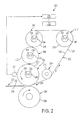
- FIG. 1 illustrates an exemplary embodiment of a xerographic apparatus
- FIG. 2 illustrates an exemplary embodiment of a fuser assembly
- FIG. 3 illustrates an exemplary embodiment of a portion of a fuser assembly including a roll with heating elements and a fuser belt;
- FIGS. 4A to 4D show calculated fuser belt outer surface temperature versus axial position curves for a fuser assembly including heating elements with two different lengths, and also for a fuser assembly including heating elements with five different lengths, for media widths of 7 in., 9 in., 11 in. and 13 in., respectively;
- FIGS 5A to 5D show calculated toner / media interface temperature versus axial position curves for a fuser assembly including heating elements with two different lengths, and also for a fuser assembly including heating elements with five different lengths, for media width ranges of 7 in. to 9 in., 9 in. to 11 in., 11 in. to 13 in., and 13 in. to 15 in., respectively.
- the disclosed embodiments include a fuser assembly for a xerographic apparatus.
- the fuser assembly includes a fuser belt; a first roll supporting the fuser belt, the first roll including a first heating element and a second heating element extending axially along the first roll and along a width of the fuser belt, the first heating element being longer than the second heating element; and a second roll supporting the fuser belt, the second roll including a third heating element and a fourth heating element extending axially along the second roll and along the width of the fuser belt, the third heating element being longer than the fourth heating element.
- the disclosed embodiments further include a fuser assembly for a xerographic apparatus, which includes a fuser belt including an outer surface; a fuser roll supporting the fuser belt, the fuser roll including a first heating element and a second heating element extending axially along the fuser roll and along a width of the fuser belt, the first heating element being longer than the second heating element; a first idler roll supporting the fuser belt, the first idler roll including a third heating element and a fourth heating element extending axially along the first idler roll and along the width of the fuser belt, the third heating element being longer than the fourth heating element; a pressure roll; a nip between the fuser roll and the pressure roll; a first temperature sensor for sensing a first temperature on the outer surface of the fuser belt at a first location; a second temperature sensor for sensing a second temperature on the outer surface of the fuser belt at a second location axially spaced from the first location; at least one power supply for supplying power to the first, second, third
- the controller receives signals from the first and second temperature sensors indicating a temperature difference between the first and second temperatures and, based on the temperature difference and on a width of a medium that is fed to the nip, controls the power supply to turn the first, second, third and fourth heating elements ON and OFF to control a temperature profile across the width of the fuser belt.
- the disclosed embodiments further include a method of fusing toner onto a medium using a fuser assembly.
- the fuser assembly includes a fuser belt supported on at least a first roll and a second roll, the fuser belt including an outer surface, a first side edge and a second side edge, the first roll including a first heating element and a second heating element extending axially along the first roll and along a width of the fuser belt defined by the first side edge and second side edge, the first and second heating elements having different lengths from each other, and the second roll including a third heating element and a fourth heating element extending axially along the second roll and along the width of the fuser belt, the third and fourth heating elements having different lengths from each other.
- the method includes sensing a first temperature on the outer surface of the fuser belt at a first location; sensing a second temperature on the outer surface of the fuser belt at a second location axially spaced from the first location; and turning the first, second, third and fourth heating elements ON and OFF to control a temperature profile across the width of the fuser belt based on the temperature difference between the first and second temperatures and on a width of the medium.
- FIG. 1 illustrates an exemplary xerographic apparatus (digital imaging system) in which embodiments of the disclosed fuser assemblies can be used.
- Such digital imaging systems are disclosed in U.S. Patent No. 6,505,832 .
- the imaging system is used to produce an image, such as a color image output in a single pass of a photoreceptor belt.
- an image such as a color image output in a single pass of a photoreceptor belt.
- embodiments of the fuser assemblies can be used in other imaging systems.
- Such systems include, e.g., multiple-pass color process systems, single or multiple pass highlight color systems, or black and white printing systems.
- printing jobs are sent from an output management system client 102 to an output management system 104.
- the output management system 104 supplies printing jobs to a print controller 106.
- a pixel counter 108 in the output management system 104 counts the number of pixels to be imaged with toner on each sheet or page of the print job, for each color.
- the pixel count information is stored in the memory of the output management system 104.
- Job control information is communicated from the print controller 106 to a controller 110.
- the xerographic apparatus 100 includes a continuous (endless) photoreceptor belt 112 supported on a drive roll 116 and rolls 118, 120.
- the drive roll 116 is connected to a drive motor 119.
- the drive motor 119 moves the photoreceptor belt 112 in the direction of arrow 114 through the xerographic stations A to I shown in FIG. 1 .
- the photoreceptor belt 112 passes through a charging station A.
- This station includes a corona generating device 121 for charging the photoconductive surface of the photoreceptor belt 112.
- the charged portion of the photoconductive surface of the photoreceptor belt 112 is advanced through an imaging/exposure station B.
- the controller 110 receives image signals from the print controller 106 representing the desired output image, and converts these signals to signals transmitted to a laser raster output scanner (ROS) 122.
- the photoreceptor belt 112 undergoes dark decay. When exposed at the exposure station B, the photoreceptor belt 112 is discharged, resulting in the photoreceptor belt 112 containing charged areas and discharged or developed areas.
- charged toner particles e.g., black particles
- the developed image is conveyed past a charging device 123 at which the photoreceptor belt 112 and developed toner image areas are recharged to a predetermined level.
- a second exposure/imaging is performed by device 124.
- the device selectively discharges the photoreceptor belt 112 on toned areas and/or bare areas, based on the image to be developed with the second color toner.
- the photoreceptor belt 112 contains areas with toner and areas without toner at relatively high voltage levels, as well as at relatively low voltage levels. These low voltage areas represent image areas.
- a negatively-charged developer material comprising, e.g., yellow toner, is transferred to latent images on the photoreceptor belt 112 using a second developer system.
- the above procedure is repeated for a third image for, e.g., magenta toner, at station E, using a third developer system, and for a fourth image and color toner, e.g., cyan toner, at station F, using a fourth developer system.
- This procedure develops a full-color composite toner image on the photoreceptor belt 112.
- a mass sensor 126 measures the developed mass per unit area.
- a negative pre-transfer dicorotron member 128 can condition the toner for transfer to a medium using positive corona discharge.
- a medium 130 e.g., paper
- the medium 130 is brought into contact with the photoreceptor belt 112 in a timed sequence so that the toner powder image developed on the photoreceptor belt 112 contacts the advancing medium 130.
- the transfer station G includes a transfer dicorotron 134 for spraying positive ions onto the backside of the medium 130.
- the ions attract the negatively-charged toner powder images from the photoreceptor belt 112 to the medium 130.
- a detack dicorotron 136 facilitates stripping of media from the photoreceptor belt 130.
- the medium continues to advance, in the direction of arrow 138, onto a conveyor 140.
- the conveyor 140 advances the medium to a fusing station H.
- the fusing station H includes a fuser assembly 150 for permanently affixing, i.e., fusing, the transferred powder image to the medium 130,.
- the fuser assembly 150 includes a heated fuser roll 152 and a pressure roll 154.
- the medium 130 is advanced between the fuser roll 152 and pressure roll 154 with the toner powder image contacting the fuser roll 152 to permanently affix the toner powder images to the medium 130.
- the medium 130 is then guided to an output device (not shown) for subsequent removal from the apparatus by the operator.
- Xerographic apparatuses can be used to make prints using media having a range of widths.
- fuser assemblies that include a fuser belt
- FIG. 2 illustrates an exemplary embodiment of a fuser assembly 200.
- Embodiments of the fuser assembly 200 can provide thermally-efficient fusing of toner on media having a wide range of widths.
- the fuser assembly 200 can be used in different types of xerographic apparatuses.
- the fuser assembly 200 can be used in the xerographic apparatus shown in FIG. 1 , in place of the fuser assembly 150.
- Embodiments of the fuser assemblies include a fuser belt supported by two or more rolls.
- the rolls include heating elements having different lengths to heat the fuser belt.
- the heating elements are turned ON and OFF to control the fuser belt temperature so as to produce a desired fuser belt and medium temperature.
- the fuser assembly 200 includes a fuser roll 202, a pressure roll 204 and a nip 206 between the fuser roll 202 and pressure roll 204.
- the fuser assembly 200 also includes multiple idler rolls 208, 210, 212 and 214.
- An endless (continuous) fuser belt 220 is supported on the fuser roll 202 and on the idler rolls 208, 210, 212 and 214.
- the fuser assembly can include less than four or more than four idler rolls.
- the fuser roll 202 is rotated counterclockwise by a drive mechanism, as indicated by arrow A, and the pressure roll 202 is rotated clockwise.
- Embodiments of the fuser belt 220 have a multi-layer construction, including at least a base layer, an intermediate layer on the base layer, and an outer layer on the intermediate layer.
- the base layer forms the inner surface of the fuser belt, which contacts the rolls supporting the fuser belt.
- the outer layer forms the outer surface of the fuser belt.
- the inner layer is composed of polyimide, or a like polymeric material;
- the intermediate layer is composed of silicone, or the like;
- the outer layer is composed of a fluoroelastomer sold under the trademark Viton® by DuPont Performance Elastomers, L.L.C., or a like polymeric material.
- the polyimide layer forms the inner surface 222
- the fluoroelastomer layer forms the outer surface 224, of the fuser belt 220.
- the base layer has a thickness of about 50 ⁇ m to about 100 ⁇ m
- the intermediate layer has a thickness of about 200 ⁇ m to about 400 ⁇ m
- the outer layer has a thickness of about 20 ⁇ m to about 40 ⁇ m.
- the fuser belt 220 typically has a width of about 350 mm to about 450 mm.
- the fuser belt 220 has a length of at least about 500 mm, about 600 mm, about 700 mm, about 800 mm, about 900 mm, about 1000 mm, or even longer.
- the fuser belt 220 has a larger surface area for wear than shorter belts and, consequently, can provide a longer service life.
- the fuser roll 202 includes a core 240
- the idler roll 208 includes a core 242
- the idler roll 210 includes a core 244
- the idler roll 212 includes a core 246.
- Each of the cores 240, 242, 244 and 246 is typically cylindrical shaped.
- the fuser roll 202 and the idler rolls 208, 210 and 212 are internally heated.
- the fuser roll 202 and idler rolls 208, 210 and 212 each include at least two heating elements.
- the fuser roll 202 includes heating elements 250, 252; the idler roll 208 includes heating elements 254, 256; the idler roll 210 includes heating elements 258, 260; and the idler roll 212 includes heating elements 262, 264.
- the heating elements are elongated lamps, e.g., tungsten quartz lamps, located inside of the respective rolls. These heating elements extend axially along the fuser roll 202 and idler rolls 208, 210, 212.
- the heating elements are powered to supply heat to the outer surface 203 of the fuser roll 202, the outer surface 209 of the idler roll 208, the outer surface 211 of the idler roll 210, and the outer surface 213 of the idler roll 212, and to the inner surface 222 of the fuser belt 220 in contact with these outer surfaces.
- the fuser roll 202 and the idler rolls 208, 210 and 212 each include at least two heating elements having different lengths from each other.
- the fuser roll 202 and the idler rolls 208, 210 and 212 each include a long heating element and a short heating element.
- the heating elements 250, 254, 258 and 262 can have the same length.
- the lengths of one of more of these heating elements can vary in order to enable better temperature uniformity throughout the media width range. These lengths can be determined based on considerations including the total maximum power needed to fuse toner on all media and the available power of the individual heating elements.
- the heating element 250 is longer than the heating element 252
- the heating element 254 is longer than the heating element 256
- the heating element 258 is longer than the heating element 260
- the heating element 262 is longer than the heating element 264.
- the heating elements 252, 256, 260 and 264 all have different lengths from each other.
- the fuser assembly 200 includes heating elements having a total of five different lengths in multiple rolls.
- the fuser assembly 200 includes heating elements having a total of up to eight different lengths in multiple rolls.
- the idler roll 212 and the fuser roll 202 are the two heated rolls that are separated by the greatest distance from each other along the fuser belt 220.
- the fuser belt 220 moves the greatest distance after it has been heated by one roll until it is then heated by another roll, when the fuser belt 220 is advanced from the fuser roll 202 to the idler roll 212.
- the fuser belt 220 is also cooled by contact with the medium 230 at the nip 206.
- the short heating element 264 in the idler roll 212 can be longer than the short heating elements 260, 256 and 252 in the idler rolls 210, 208 and the fuser roll 202, respectively.
- the short heating elements can have a different arrangement and the longest one of the short heating elements can be provided in an idler roll other than the idler roll 212.
- the heating element 260 in the idler roll 210 is longer than the heating element 256 in the idler roll 208, and the heating element 256 is longer than heating element 252 in the fuser roll 202.
- FIG. 3 depicts a portion of a fuser assembly in a xerographic apparatus.
- the fuser assembly includes a roll 305, and a fuser belt 320 supported on the roll 305.
- a medium 330 is shown in contact with the outer surface 324 of the fuser belt 320.
- the roll 305 can have the same general structure as any one of the fuser roll 202 and idler rolls 208, 210, 212. The length of the short heating element is different in each of these rolls.
- roll 305 has an outboard end 317 and an opposite inboard end 319.
- roll 305 can have a length, L, of, e.g., about 400 mm to about 500 mm, and the fuser belt 320 can have a width, w b , of, e.g., about 350 mm to about 450 mm.
- the xerographic apparatus includes a front side 380 and a rear side 382.
- Roll 305 is oriented such that the outboard end 317 faces the front side 380, and the inboard end 319 faces the rear side 382.
- the fuser belt 320 has an outboard edge 321 and an inboard edge 323.
- the medium 330 is "outboard registered,” meaning that the outboard edge 331 of the medium 330 is closer to the outboard edge 321 of the fuser belt 320 than the inboard edge 333 of the medium 330 is located with respect to the inboard edge 323 of the fuser belt 320.
- the outboard edge 331 of the medium 330 is spaced by a distance, x 1 , from the outboard end 317 of roll 305.
- the medium 330 can be "inboard registered” in the xerographic apparatus. In such embodiments, the inboard edge 333 of the medium 330 is located closer to the inboard edge 323 of the fuser belt 320 than the outboard edge 331 of the medium 330 is located with respect to the outboard edge 321 of the fuser belt 320 (not shown). In other embodiments, the medium 330 can be "center registered” in the xerographic apparatus. In such embodiments, the medium 330 is axially centered on the fuser belt 320 (not shown).
- roll 305 includes a long heating element 362 and a short heating element 364.
- the heating elements 362, 364 can be heating lamps, which extend axially along the length of roll 305.
- the heating element 362 has an outboard end 363 and an opposite inboard end 365, and the heating element 364 has an outboard end 367 and an opposite inboard end 369.
- the outboard ends 363, 367 are axially aligned with each other and spaced by a distance, x 2 , from the outboard end 317 of roll 305.
- the inboard end 365 of the long heating element 362 extends axially beyond the inboard end 369 of the short heating element 364, such that the inboard end 365 of the long heating element 362 is closer to the inboard end 319 of the roll 305 than is the inboard end 369 of the short heating element 364.
- the fuser belt 320 can be centered along the longitudinal axis of roll 305 (i.e., axially centered) between the outboard end 317 and the inboard end 319.
- the outboard edge 321 of the fuser belt 320 is spaced by a distance, x 3 , from the outboard end 317 of the roll 305.
- the outboard ends 363, 367 of the respective heating elements 362, 364 extend axially outward beyond the outboard edge 321 of the fuser belt 320.
- the inboard end 365 of the long heating element 362 extends axially outward beyond the inboard edge 323 of the fuser belt 320, while the inboard end 369 of the short heating element 364 is located axially inward from the inboard edge 323.
- the medium 330 can have a width, w s1 , or a narrower width, w s2 .
- An inboard temperature sensor 370 and an outboard temperature sensor 372 are positioned to sense the temperature of the outer surface 324 of the fuser belt 320 at two axially-spaced locations on the outer surface 324.
- an optional intermediate temperature sensor 374 can be located axially between the inboard temperature sensor 370 and the outboard temperature sensor 372 to provide a third temperature measurement at the outer surface 324 of the fuser belt 320.
- the temperature sensors 370, 372 can be positioned to sense the temperature of the outer surface of the fuser belt at, or upstream and adjacent, the fuser roll, where the temperature of the fuser belt reaches a maximum.
- the temperature sensors 370, 372 can be connected to a controller for controlling the heating elements in the different heated rolls.
- a temperature sensor 280 is positioned to measure the temperature of the outer surface 224 of the fuser belt 220 at the fuser roll 202.
- the temperature sensor 280 is provides feedback to the controller 270.
- the controller 270 controls the power supply 272, which controls the heating elements in the heated fuser roll 202 and idler rolls 208, 210, 212.
- the outboard temperature sensor 372 can be spaced by the same distance, d 2 , from the outboard edge 321 of the fuser belt 320, and spaced by the same distance, d 1 , from the outboard edge 231 of the medium 330, for different media widths.
- d 2 can be about 20 mm to about 30 mm
- d 1 can be about 5 mm to about 10 mm.
- the inboard temperature sensor 370 can be axially positioned relative to the location of the inboard edge of media for each selected media width sub-range. In embodiments, the inboard temperature sensor 370 can be axially positioned based on the width of the narrowest and the widest media within a given media width sub-range (i.e., based on the location of the inboard edge of such media). For example, for an exemplary broad numerical range of media widths of 7 in. to 15 in. that embodiments of the fuser assembly can be used to print based on the width of the fuser belt, this broad numerical range can be divided into numerical sub-ranges of the media width, e.g., 7 in. to 9 in.
- the inboard temperature sensor 370 can be located at a position midway between the inboard edge for the narrowest-width medium and the inboard edge for the widest-width medium of that sub-range. For example, in an embodiment in which the width w s1 shown in FIG. 3 indicates a medium having a width of 11 in.
- the inboard temperature sensor 370 can be located about 1 in. (about 25 mm) inwardly from the inboard edge 333 of the 11 in.-wide medium (as shown), or, stated differently, about 1 in. (25 mm) outwardly from the inboard edge 335 of the 9 in.-wide medium.
- the medium when a medium having a width falling within the broad numerical range is to be printed, the medium is assigned to one of the sub-ranges.
- Information regarding the media width for a print job can be input to the xerographic apparatus by a user.
- the heating elements are turned ON and OFF according to an algorithm that controls the temperature profile across the width of the fuser belt based on the temperature difference determined by the inboard and outboard temperature sensors on the outer surface of the fuser belt and on the sub-range to which the medium has been assigned.
- the algorithm shown in TABLE 1 can be used.
- the fuser assembly can include more than one inboard temperature sensor.
- the two or more inboard temperature sensors can be axially spaced from each other in a sensor array also including the outboard temperature sensor.
- at least one additional inboard temperature sensor can be positioned to sense the outer surface temperature of the fuser belt axially outward from the inboard temperature sensor 372.
- the number of inboard temperature sensors can be determined by optimization based on the algorithm that is used to control the ON/OFF state of the heating elements of the heated rolls of the fuser assembly.
- the algorithm can be provided in a memory connected to the controller 270.
- the algorithm decides which heating element will be used to heat the fuser belt 220 based on both the media width and the difference between the inboard and outboard temperatures.
- the inboard temperature is lower than the outboard temperature (by a selected value)
- the long heating elements will be used
- the short heating elements will be used.
- the long and short heating elements used will depend on the media width in order to enable closer control of the fuser belt and media width temperature uniformity.
- the inboard temperature sensor used in combination with the outboard temperature sensor can be selected based on the width of media that are to be printed with the fuser assembly. For example, for wider media, an inboard temperature sensor used in combination with the outboard temperature sensor can be located closer to the inboard ends of the heated rolls than an inboard temperature sensor used for printing of narrower media.
- the respective outboard ends of the fuser roll 202 and idler rolls 208, 210, 212 can be approximately axially aligned with respect to each other.
- the outboard ends of the heating elements 262, 264 of the idler roll 212; the outboard ends of the heating elements 258, 260 of the idler roll 210; the outboard ends of the heating elements 254, 256 of the idler roll 208; and the outboard ends of the heating elements 250, 252 of the fuser roll 202 can be axially aligned with each other and spaced by a distance equal to the distance x 2 ( FIG.
- the outboard end of the fuser belt 220 can be spaced by a distance equal to the distance x 3 ( FIG. 3 ) from the outboard ends of the idler rolls 212, 210, 208 and the fuser roll 202.
- the outboard edges of the media are spaced by a distance equal to the distance x 1 ( FIG. 3 ) from the outboard ends of the idler rolls 212, 210, 208 and the fuser roll 202.
- the medium 230 e.g., paper or other print medium
- the medium 230 with at least one toner image (text and/or other type(s) of image) on at least the surface 232 is fed to the nip 206 by a sheet feeding apparatus.
- the heated idler rolls 208, 210, 212 and fuser roll 202 heat the fuser belt 220 to a sufficiently-high temperature to fuse (fix) the toner image(s) on the medium 230.
- the outer surface 224 of the rotating fuser belt 220 contacts the surface 232 of the medium 230, and the outer surface 205 of the pressure roll 204 contacts the opposite surface 234 of the medium 230.
- the pressure roll 204 and fuser belt 220 apply sufficient pressure and heat to the medium 230 to fuse the toner.
- the fusing temperature for fusing the toner on the medium 230 is based on various factors, including the thickness (weight) of the medium 230, and whether the medium 230 is coated or uncoated.
- the fusing temperature can be, e.g., about 150°C to about 210°C for various media.
- the power supply 272 is connected to the heating elements of the fuser roll 202 and idler rolls 208, 210, 212 in any conventional manner.
- the controller 270 controls the power supply 272 to power the heating elements of the fuser roll 202 and idler rolls 208, 210, 212 based on characteristics of the media to be printed by the apparatus.
- the axial (i.e., width dimension) temperature profile of the fuser belt 220 is controlled by turning the short and long heating elements of each of the heated rolls ON and OFF.
- the axial temperature profile of the fuser belt 220 can be varied depending on the media width. By including multiple heating rolls, with heating elements of different lengths, the fuser assembly 200 can be used to process a broad range of media widths.
- a potential broad range of media widths that may be printed with the fuser assembly 200 can be divided into two or more sub-ranges.
- a control algorithm is defined for the heating elements of the fuser roll 202 and idler rolls 208, 210, 212.
- the control algorithm causes the short and long heating elements in these rolls to be turned ON and OFF based on temperature feedback provided at axially-spaced locations in the cross-process direction (i.e., width direction) of the fuser belt 220, and on the width of the media to be printed.
- the control algorithm causes the long heating elements and the short heating elements of the heated fuser roll 202 and idler rolls 208, 210, 212 to be turned ON and OFF based on the temperature difference, ⁇ T, between two axially-spaced locations of the fuser belt 220, as determined by the inboard temperature sensor 370 and the outboard temperature sensor 372.
- ⁇ T depending on whether ⁇ T is above or below a selected value, certain heating elements are turned ON and other heating elements are turned OFF, to control the temperature profile across the width of the fuser belt.
- the maximum fuser belt temperature typically occurs at a location between the idler roll 208 and contact with the medium 230. In embodiments, the fuser belt temperature can be measured at this location.
- the value of ⁇ T can be selected based on the desired level of uniformity of the temperature profile across the width of the fuser belt.
- the operation of the fuser assembly 200 shown in FIG. 2 for printing media is modeled using a three-dimensional heat transfer code.
- the exemplary algorithm shown in TABLE 1 is used to turn the heating elements of the fuser roll 202 and idler rolls 208, 210, 212 of the fuser assembly 200 ON and OFF.
- the eight heating elements have the following five different lengths: heating elements 250, 254, 258, 262 / 420 mm; heating element 264 / 365 mm; heating element 260 / 315 mm; heating element 256 / 260 mm, and heating element 252 / 210 mm.
- the broad range of the media width, w of 7 in. to 15 in.
- the fuser belt 220 has a width of 400 mm.
- the media are outboard registered with respect to the fuser belt 220 as shown in FIG. 3 .
- the outboard edges of the media are spaced from the outboard ends of the fuser roll 202 and idler rolls 208, 210, 212 by a distance of 52 mm, and are spaced from the outboard edge of the fuser belt 220 by a distance of 17 mm.
- toner is fused on the media at the nip at a rate of 165 pages/min. with the fuser assembly.
- ⁇ T equals the difference between the temperatures on the fuser belt outer surface measured at the locations of the inboard temperature sensor and the outboard temperature sensor.
- the inboard temperature sensor is located at a position midway between the inboard edge for the narrowest-width medium and the inboard edge for the widest-width medium of that range.
- 2°C is the value of ⁇ T used for turning the heating elements ON and OFF in the algorithm.
- the controller 270 causes the long heating elements to be turned on and the short heating elements to be turned OFF when the inboard-side (un-registered side) temperature of the fuser belt 220 is less than 2°C higher, or is lower, than the outboard-side temperature of the fuser belt 220, and causes the long heating elements to be turned OFF and the short heating elements turned ON when the inboard-side temperature is more than 2°C higher than the onboard-side temperature.
- this control is exemplified for the idler rolls 212, 210 and 208 and the fuser roll 202 for the media width range of 7 ⁇ w ⁇ 9; the idler rolls 212, 210 and 208 for the media width range of 9 ⁇ w ⁇ 11; the idler roll 212, 210 for the media width range of 11 ⁇ w ⁇ 13; and the idler roll 212 for the media width range of 13 ⁇ w ⁇ 15.
- FIGS. 4A to 4D show the calculated outer surface temperature versus axial position of the fuser belt 220 for media (paper having a grammage of 350 gsm) having widths of 7 in., 9 in., 11 in. and 13 in., respectively, for the fuser assembly 200 including the five different heating element lengths (symbol " ⁇ ").
- 0 mm represents the outboard edge
- 400 mm represents the inboard edge, of the fuser belt 220.
- the outer surface temperature of the fuser belt is determined at the exit of the idler roll 208 directly upstream from the fuser roll 202 after producing 600 prints.
- FIGS. 4A to 4D also show the calculated outer surface temperature versus axial position of the fuser belt for media widths of 7 in., 9 in., 11 in. and 13 in., respectively, for a fuser assembly also including eight heating elements, but only two different heating element lengths (symbol " ⁇ ").
- the fuser roll 202 and idler rolls 212, 210 and 208 each include a long heating element and a short heating element.
- the long heating elements in each of the fuser roll 202 and idler rolls 212, 210 and 208 have the same length of 365 mm
- the short heating elements in each of the fuser roll 202 and idler rolls 212, 210 and 208 have the same length of 210 mm.
- each of these rolls includes a long heating element and a short heating element having the same lengths.
- the fuser belt has a width of 400 mm and the same multi-layer structure as in the fuser belt used with the arrangement including five different heating element lengths.
- the long and short heating elements are turned ON and OFF to control the temperature profile of the fuser belt for each media width based on the difference in temperature of the inboard and outboard sensors.
- the fuser assembly 200 can be used to process a broad range of media widths.
- the heating element configuration and algorithm can be used to prevent the inboard side region of the fuser belt 220 from being heated to above a desired maximum temperature.
- TABLE 2 shows the calculated maximum temperature reached at the outer surface of the fuser belt for the fuser assembly including heating elements with only two different lengths, and the fuser assembly including heating elements with five different lengths, for media widths of 7 in., 9 in., 11 in. and 13 in.
- using different heating element lengths in each roll reduces the maximum fuser belt temperature significantly for narrow media (e.g., media having a width of less than 11 in.), while it also does not compromise the maximum fuser belt outer surface temperature reached for wide media ( FIGS. 5C and 5D ).
- the fuser belt can have a longer service life, and fuser belt edge wear can be decreased.
- FIGS. 4A to 4D also show that a significantly lower temperature is reached on the outer surface of the fuser belt outside the media path using five different heating element lengths in combination with the algorithm shown in TABLE 1. This effect is greater for media widths of 7 in. to 11 in. ( FIGS. 4A to 4C ). For wider media (i.e., media having a width of 13 in. to 15 in.), the fuser belt surface temperatures attained with the five-heating element length configuration are similar to those attained using a two-heating element length configuration.
- TABLE 3 shows the calculated total power consumption for fusing toner on media at a rate of 165 pages/min. using the fuser assembly including heating elements with only two different lengths, and the fuser assembly including heating elements with five different lengths. As shown, for each media width, the total power consumption for the fuser assembly with five heating element lengths is lower than that for the fuser assembly with only two heating element lengths.
- the five-heating element length configuration reduces the total power consumption significantly for narrower media (e.g., media having a width of less than 11 inches), and has comparable power consumption to the two-heating element length configuration for wider media. By reducing the total power consumption in this manner, the operating cost of xerographic apparatuses can be reduced.
- FIGS. 5A to 5D show calculated toner/medium interface temperature versus axial position curves for the same fuser assemblies including heating elements (lamps) with five different lengths and only two different lengths that are used to produce the curves shown in FIGS. 4A to 4D .
- the media used in the model are paper having a grammage of 350 gsm.
- the exemplary algorithm in TABLE 1 is used to control the heating elements in the fuser assembly including five different heating element lengths.
- FIG. 5A shows curves for media having a width of 7 in. and 9 in;
- FIG. 5B shows curves for media having a width of 9 in. and 11 in;
- FIG. 5C shows curves for media having a width of 11 in. and 13 in; and
- FIGS. 5A to 5D shows curves for media having a width of 13 in. and 15 in, after making 600 prints for each of the media widths.
- the axial positions of the outboard side ("OB Side") and inboard side (“IB Side") of the fuser belt are indicated in FIGS. 5A to 5D .
- the axial temperature profile at the toner /medium interface after making the prints is more uniform for each media width for the fuser assembly with five different heating element lengths.
- FIG. 5A shows that a more uniform toner / medium interface temperature profile is achieved with the five-heating element length configuration and control scheme for 7 in. wide media as compared to a two-heating element length scheme.
- gloss uniformity in the cross-process direction of media is improved.
- FIG. 5A also shows that a highly-uniform toner/media interface temperature profile is produced with the five-heating element length configuration and the algorithm for 9 in. wide media, which is the maximum width of the media width range of 7 in. to 9 in. considered. It is believed that the five-heating element length configuration and the algorithm in TABLE 1 can provide desirable results for all media widths within the range of 7 in. to 9 in.
- FIGS. 5B to 5D demonstrate that similar conclusions to those made regarding the curves in FIG. 5A can also be made for media widths within the ranges of 9 in. to 11 in., 11 in. to 13 in., and 13 in. to 15 in.
- the results shown in FIGS. 5B and 5C demonstrate significant improvements that can be provided by the five-heating element length configuration in comparison to a two-heating element length configuration in the narrow to medium media width ranges.
- FIG. 5D shows that the temperature profile achieved for wide media (13 in. to 15 in.) is not compromised by using a five-heating element scheme.
- the use of a fuser assembly including multiple heating rolls, with heating elements of different lengths in the rolls, and controlling the heating elements according to embodiments of the control algorithm, such as the algorithm shown in TABLE 1, makes the fuser assembly more thermally efficient.
- the fuser belt temperature outside the media path can be reduced, thereby reducing thermal losses to the ambient. Reducing the fuser belt temperature outside the paper path can increase the life of the fuser belt outer layer.
- belt edge-wear can be reduced, thereby also improving belt life.
- Embodiments of the fuser assembly can be used for fusing toner in xerographic apparatuses that use oil for reducing offset, as well as in "oil-less" apparatuses that use toner particles containing a release agent, such as wax, instead of using release oil.
- the structure and composition of the layers of the fuser belt can be varied depending on whether release oil is used or not used in the xerographic apparatus.
Abstract
Description
- Fuser assemblies, xerographic apparatuses, and methods of fusing toner on media are disclosed.
- In a typical xerographic printing process, toner images are formed on media, and then the toner is heated to fuse the toner on the media. One process used for thermal fusing toner onto media uses a fuser including a pressure roll, a fuser roll and a fuser belt positioned between these rolls. During operation, a medium with a toner image is fed to a nip between the pressure and fuser rolls, and the pressure roll presses the medium onto the heated fuser belt to fuse the toner onto the medium.
- It would be desirable to provide fuser assemblies including fuser belts that can be used to print media of different widths efficiently.
- Fuser assemblies for xerographic apparatuses, xerographic apparatuses and methods of fusing toner on media in xerographic apparatuses, are provided. An exemplary embodiment of the fuser assemblies includes a fuser belt; a first roll supporting the fuser belt, the first roll including a first heating element and a second heating element extending axially along the first roll and along a width of the fuser belt, the first heating element being longer than the second heating element; and a second roll supporting the fuser belt, the second roll including a third heating element and a fourth heating element extending axially along the second roll and along the width of the fuser belt, the third heating element being longer than the fourth heating element.
-
FIG. 1 illustrates an exemplary embodiment of a xerographic apparatus; -
FIG. 2 illustrates an exemplary embodiment of a fuser assembly; -
FIG. 3 illustrates an exemplary embodiment of a portion of a fuser assembly including a roll with heating elements and a fuser belt; -
FIGS. 4A to 4D show calculated fuser belt outer surface temperature versus axial position curves for a fuser assembly including heating elements with two different lengths, and also for a fuser assembly including heating elements with five different lengths, for media widths of 7 in., 9 in., 11 in. and 13 in., respectively; and -
FIGS 5A to 5D show calculated toner / media interface temperature versus axial position curves for a fuser assembly including heating elements with two different lengths, and also for a fuser assembly including heating elements with five different lengths, for media width ranges of 7 in. to 9 in., 9 in. to 11 in., 11 in. to 13 in., and 13 in. to 15 in., respectively. - The disclosed embodiments include a fuser assembly for a xerographic apparatus. The fuser assembly includes a fuser belt; a first roll supporting the fuser belt, the first roll including a first heating element and a second heating element extending axially along the first roll and along a width of the fuser belt, the first heating element being longer than the second heating element; and a second roll supporting the fuser belt, the second roll including a third heating element and a fourth heating element extending axially along the second roll and along the width of the fuser belt, the third heating element being longer than the fourth heating element.
- The disclosed embodiments further include a fuser assembly for a xerographic apparatus, which includes a fuser belt including an outer surface; a fuser roll supporting the fuser belt, the fuser roll including a first heating element and a second heating element extending axially along the fuser roll and along a width of the fuser belt, the first heating element being longer than the second heating element; a first idler roll supporting the fuser belt, the first idler roll including a third heating element and a fourth heating element extending axially along the first idler roll and along the width of the fuser belt, the third heating element being longer than the fourth heating element; a pressure roll; a nip between the fuser roll and the pressure roll; a first temperature sensor for sensing a first temperature on the outer surface of the fuser belt at a first location; a second temperature sensor for sensing a second temperature on the outer surface of the fuser belt at a second location axially spaced from the first location; at least one power supply for supplying power to the first, second, third and fourth heating elements; and a controller connected to the power supply and to the first and second temperature sensors. The controller receives signals from the first and second temperature sensors indicating a temperature difference between the first and second temperatures and, based on the temperature difference and on a width of a medium that is fed to the nip, controls the power supply to turn the first, second, third and fourth heating elements ON and OFF to control a temperature profile across the width of the fuser belt.
- The disclosed embodiments further include a method of fusing toner onto a medium using a fuser assembly. The fuser assembly includes a fuser belt supported on at least a first roll and a second roll, the fuser belt including an outer surface, a first side edge and a second side edge, the first roll including a first heating element and a second heating element extending axially along the first roll and along a width of the fuser belt defined by the first side edge and second side edge, the first and second heating elements having different lengths from each other, and the second roll including a third heating element and a fourth heating element extending axially along the second roll and along the width of the fuser belt, the third and fourth heating elements having different lengths from each other. The method includes sensing a first temperature on the outer surface of the fuser belt at a first location; sensing a second temperature on the outer surface of the fuser belt at a second location axially spaced from the first location; and turning the first, second, third and fourth heating elements ON and OFF to control a temperature profile across the width of the fuser belt based on the temperature difference between the first and second temperatures and on a width of the medium.
-
FIG. 1 illustrates an exemplary xerographic apparatus (digital imaging system) in which embodiments of the disclosed fuser assemblies can be used. - Such digital imaging systems are disclosed in
U.S. Patent No. 6,505,832 . The imaging system is used to produce an image, such as a color image output in a single pass of a photoreceptor belt. It will be understood, however, that embodiments of the fuser assemblies can be used in other imaging systems. Such systems include, e.g., multiple-pass color process systems, single or multiple pass highlight color systems, or black and white printing systems. - As shown in
FIG. 1 , printing jobs are sent from an outputmanagement system client 102 to anoutput management system 104. Theoutput management system 104 supplies printing jobs to aprint controller 106. Apixel counter 108 in theoutput management system 104 counts the number of pixels to be imaged with toner on each sheet or page of the print job, for each color. The pixel count information is stored in the memory of theoutput management system 104. Job control information is communicated from theprint controller 106 to acontroller 110. - The
xerographic apparatus 100 includes a continuous (endless)photoreceptor belt 112 supported on adrive roll 116 androlls drive roll 116 is connected to adrive motor 119. Thedrive motor 119 moves thephotoreceptor belt 112 in the direction ofarrow 114 through the xerographic stations A to I shown inFIG. 1 . - During the printing process, the
photoreceptor belt 112 passes through a charging station A. This station includes acorona generating device 121 for charging the photoconductive surface of thephotoreceptor belt 112. - Next, the charged portion of the photoconductive surface of the
photoreceptor belt 112 is advanced through an imaging/exposure station B. At this station, thecontroller 110 receives image signals from theprint controller 106 representing the desired output image, and converts these signals to signals transmitted to a laser raster output scanner (ROS) 122. Thephotoreceptor belt 112 undergoes dark decay. When exposed at the exposure station B, thephotoreceptor belt 112 is discharged, resulting in thephotoreceptor belt 112 containing charged areas and discharged or developed areas. - At a first development station C, charged toner particles, e.g., black particles, are attracted to the electrostatic latent image on the
photoreceptor belt 112. The developed image is conveyed past acharging device 123 at which thephotoreceptor belt 112 and developed toner image areas are recharged to a predetermined level. - A second exposure/imaging is performed by
device 124. The device selectively discharges thephotoreceptor belt 112 on toned areas and/or bare areas, based on the image to be developed with the second color toner. At this point of the process, thephotoreceptor belt 112 contains areas with toner and areas without toner at relatively high voltage levels, as well as at relatively low voltage levels. These low voltage areas represent image areas. At a second developer station D, a negatively-charged developer material comprising, e.g., yellow toner, is transferred to latent images on thephotoreceptor belt 112 using a second developer system. - The above procedure is repeated for a third image for, e.g., magenta toner, at station E, using a third developer system, and for a fourth image and color toner, e.g., cyan toner, at station F, using a fourth developer system. This procedure develops a full-color composite toner image on the
photoreceptor belt 112. Amass sensor 126 measures the developed mass per unit area. - In cases where some toner charge is totally neutralized, or the polarity reversed, a negative pre-transfer
dicorotron member 128 can condition the toner for transfer to a medium using positive corona discharge. - In the process, a medium 130 (e.g., paper) is advanced to a transfer station G by a
feeding apparatus 132. Themedium 130 is brought into contact with thephotoreceptor belt 112 in a timed sequence so that the toner powder image developed on thephotoreceptor belt 112 contacts the advancingmedium 130. - The transfer station G includes a
transfer dicorotron 134 for spraying positive ions onto the backside of themedium 130. The ions attract the negatively-charged toner powder images from thephotoreceptor belt 112 to themedium 130. Adetack dicorotron 136 facilitates stripping of media from thephotoreceptor belt 130. - After the toner image has been transferred, the medium continues to advance, in the direction of
arrow 138, onto aconveyor 140. Theconveyor 140 advances the medium to a fusing station H. The fusing station H includes afuser assembly 150 for permanently affixing, i.e., fusing, the transferred powder image to the medium 130,. Thefuser assembly 150 includes aheated fuser roll 152 and apressure roll 154. The medium 130 is advanced between thefuser roll 152 andpressure roll 154 with the toner powder image contacting thefuser roll 152 to permanently affix the toner powder images to the medium 130. The medium 130 is then guided to an output device (not shown) for subsequent removal from the apparatus by the operator. - After the medium 130 has been separated from the
photoreceptor belt 112, residual toner particles on non-image areas on the photoconductive surface of thephotoreceptor belt 112 are removed from the photoconductive surface at a cleaning station I. - Xerographic apparatuses can be used to make prints using media having a range of widths. In fuser assemblies that include a fuser belt, it is desirable to use different fuser belt temperature profiles for printing different media widths in order to reduce or prevent the occurrence of cross-process gloss differentials and reduce overheating of the fuser belt outside the media path.
-
FIG. 2 illustrates an exemplary embodiment of afuser assembly 200. Embodiments of thefuser assembly 200 can provide thermally-efficient fusing of toner on media having a wide range of widths. Thefuser assembly 200 can be used in different types of xerographic apparatuses. For example, thefuser assembly 200 can be used in the xerographic apparatus shown inFIG. 1 , in place of thefuser assembly 150. - Embodiments of the fuser assemblies include a fuser belt supported by two or more rolls. The rolls include heating elements having different lengths to heat the fuser belt. The heating elements are turned ON and OFF to control the fuser belt temperature so as to produce a desired fuser belt and medium temperature.
- In the embodiment shown in
FIG. 2 , thefuser assembly 200 includes afuser roll 202, apressure roll 204 and a nip 206 between thefuser roll 202 andpressure roll 204. Thefuser assembly 200 also includes multiple idler rolls 208, 210, 212 and 214. An endless (continuous)fuser belt 220 is supported on thefuser roll 202 and on the idler rolls 208, 210, 212 and 214. In other embodiments, the fuser assembly can include less than four or more than four idler rolls. In embodiments, thefuser roll 202 is rotated counterclockwise by a drive mechanism, as indicated by arrow A, and thepressure roll 202 is rotated clockwise. - Embodiments of the
fuser belt 220 have a multi-layer construction, including at least a base layer, an intermediate layer on the base layer, and an outer layer on the intermediate layer. The base layer forms the inner surface of the fuser belt, which contacts the rolls supporting the fuser belt. The outer layer forms the outer surface of the fuser belt. In an exemplary embodiment, the inner layer is composed of polyimide, or a like polymeric material; the intermediate layer is composed of silicone, or the like; and the outer layer is composed of a fluoroelastomer sold under the trademark Viton® by DuPont Performance Elastomers, L.L.C., or a like polymeric material. In the embodiment, the polyimide layer forms theinner surface 222, and the fluoroelastomer layer forms theouter surface 224, of thefuser belt 220. Typically, the base layer has a thickness of about 50 µm to about 100 µm, the intermediate layer has a thickness of about 200 µm to about 400 µm, and the outer layer has a thickness of about 20 µm to about 40 µm. Thefuser belt 220 typically has a width of about 350 mm to about 450 mm. - In embodiments of the
fuser assembly 200, thefuser belt 220 has a length of at least about 500 mm, about 600 mm, about 700 mm, about 800 mm, about 900 mm, about 1000 mm, or even longer. By using a longer fuser belt for embodiments of thefuser belt 220, thefuser belt 220 has a larger surface area for wear than shorter belts and, consequently, can provide a longer service life. - In embodiments, the
fuser roll 202 includes acore 240, theidler roll 208 includes acore 242, theidler roll 210 includes acore 244, and theidler roll 212 includes acore 246. Each of thecores - In the
fuser assembly 200, thefuser roll 202 and the idler rolls 208, 210 and 212 are internally heated. In embodiments, thefuser roll 202 and idler rolls 208, 210 and 212 each include at least two heating elements. As shown inFIG. 2 , thefuser roll 202 includesheating elements idler roll 208 includesheating elements idler roll 210 includesheating elements idler roll 212 includesheating elements fuser roll 202 and idler rolls 208, 210, 212. The heating elements are powered to supply heat to theouter surface 203 of thefuser roll 202, theouter surface 209 of theidler roll 208, theouter surface 211 of theidler roll 210, and theouter surface 213 of theidler roll 212, and to theinner surface 222 of thefuser belt 220 in contact with these outer surfaces. - In embodiments, the
fuser roll 202 and the idler rolls 208, 210 and 212 each include at least two heating elements having different lengths from each other. In embodiments, thefuser roll 202 and the idler rolls 208, 210 and 212 each include a long heating element and a short heating element. In embodiments, theheating elements heating element 250 is longer than theheating element 252, theheating element 254 is longer than theheating element 256, theheating element 258 is longer than theheating element 260, and theheating element 262 is longer than theheating element 264. - In embodiments, the
heating elements heating elements fuser assembly 200 includes heating elements having a total of five different lengths in multiple rolls. In such embodiments, when theheating elements fuser assembly 200 includes heating elements having a total of up to eight different lengths in multiple rolls. - In the embodiment of the
fuser assembly 200 shown inFIG. 2 , theidler roll 212 and thefuser roll 202 are the two heated rolls that are separated by the greatest distance from each other along thefuser belt 220. In the embodiment, thefuser belt 220 moves the greatest distance after it has been heated by one roll until it is then heated by another roll, when thefuser belt 220 is advanced from thefuser roll 202 to theidler roll 212. Thefuser belt 220 is also cooled by contact with the medium 230 at thenip 206. To re-heat thefuser belt 220 more efficiently after it has contacted the medium 230 at thenip 206 and then been advanced from thefuser roll 202 to theidler roll 212, in embodiments, theshort heating element 264 in theidler roll 212 can be longer than theshort heating elements fuser roll 202, respectively. By placing the longest one of the short heating elements inside theidler roll 212, a larger amount of heat can be supplied across a greater axial length of theidler roll 212, and a greater width of thefuser belt 220, by the twoheating elements idler roll 212. - In embodiments, the
heating element 260 in theidler roll 210 is longer than theheating element 256 in theidler roll 208, and theheating element 256 is longer thanheating element 252 in thefuser roll 202. -
FIG. 3 depicts a portion of a fuser assembly in a xerographic apparatus. The fuser assembly includes aroll 305, and afuser belt 320 supported on theroll 305. A medium 330 is shown in contact with theouter surface 324 of thefuser belt 320. Theroll 305 can have the same general structure as any one of thefuser roll 202 and idler rolls 208, 210, 212. The length of the short heating element is different in each of these rolls. As shown,roll 305 has anoutboard end 317 and an oppositeinboard end 319. In embodiments, roll 305 can have a length, L, of, e.g., about 400 mm to about 500 mm, and thefuser belt 320 can have a width, wb, of, e.g., about 350 mm to about 450 mm. - As shown in
FIG. 3 the xerographic apparatus includes afront side 380 and arear side 382.Roll 305 is oriented such that theoutboard end 317 faces thefront side 380, and theinboard end 319 faces therear side 382. Thefuser belt 320 has anoutboard edge 321 and aninboard edge 323. InFIG. 3 , the medium 330 is "outboard registered," meaning that theoutboard edge 331 of the medium 330 is closer to theoutboard edge 321 of thefuser belt 320 than theinboard edge 333 of the medium 330 is located with respect to theinboard edge 323 of thefuser belt 320. As shown, theoutboard edge 331 of the medium 330 is spaced by a distance, x1, from theoutboard end 317 ofroll 305. - In other embodiments, the medium 330 can be "inboard registered" in the xerographic apparatus. In such embodiments, the
inboard edge 333 of the medium 330 is located closer to theinboard edge 323 of thefuser belt 320 than theoutboard edge 331 of the medium 330 is located with respect to theoutboard edge 321 of the fuser belt 320 (not shown). In other embodiments, the medium 330 can be "center registered" in the xerographic apparatus. In such embodiments, the medium 330 is axially centered on the fuser belt 320 (not shown). - As shown,
roll 305 includes along heating element 362 and ashort heating element 364. In the embodiment, theheating elements roll 305. Theheating element 362 has anoutboard end 363 and an oppositeinboard end 365, and theheating element 364 has anoutboard end 367 and an oppositeinboard end 369. The outboard ends 363, 367 are axially aligned with each other and spaced by a distance, x2, from theoutboard end 317 ofroll 305. Theinboard end 365 of thelong heating element 362 extends axially beyond theinboard end 369 of theshort heating element 364, such that theinboard end 365 of thelong heating element 362 is closer to theinboard end 319 of theroll 305 than is theinboard end 369 of theshort heating element 364. - As shown, the
fuser belt 320 can be centered along the longitudinal axis of roll 305 (i.e., axially centered) between theoutboard end 317 and theinboard end 319. Theoutboard edge 321 of thefuser belt 320 is spaced by a distance, x3, from theoutboard end 317 of theroll 305. The outboard ends 363, 367 of therespective heating elements outboard edge 321 of thefuser belt 320. Theinboard end 365 of thelong heating element 362 extends axially outward beyond theinboard edge 323 of thefuser belt 320, while theinboard end 369 of theshort heating element 364 is located axially inward from theinboard edge 323. - As shown in
FIG. 3 the medium 330 can have a width, ws1, or a narrower width, ws2. Aninboard temperature sensor 370 and anoutboard temperature sensor 372 are positioned to sense the temperature of theouter surface 324 of thefuser belt 320 at two axially-spaced locations on theouter surface 324. As shown, an optionalintermediate temperature sensor 374 can be located axially between theinboard temperature sensor 370 and theoutboard temperature sensor 372 to provide a third temperature measurement at theouter surface 324 of thefuser belt 320. In embodiments, thetemperature sensors 370, 372 (and optionally 374) can be positioned to sense the temperature of the outer surface of the fuser belt at, or upstream and adjacent, the fuser roll, where the temperature of the fuser belt reaches a maximum. Thetemperature sensors 370, 372 (and optionally 374) can be connected to a controller for controlling the heating elements in the different heated rolls. For example, in thefuser assembly 200 shown inFIG. 2 , atemperature sensor 280 is positioned to measure the temperature of theouter surface 224 of thefuser belt 220 at thefuser roll 202. Thetemperature sensor 280 is provides feedback to thecontroller 270. Thecontroller 270 controls thepower supply 272, which controls the heating elements in theheated fuser roll 202 and idler rolls 208, 210, 212. - In embodiments, the
outboard temperature sensor 372 can be spaced by the same distance, d2, from theoutboard edge 321 of thefuser belt 320, and spaced by the same distance, d1, from the outboard edge 231 of the medium 330, for different media widths. Typically, d2 can be about 20 mm to about 30 mm, and d1 can be about 5 mm to about 10 mm. - In embodiments, the
inboard temperature sensor 370 can be axially positioned relative to the location of the inboard edge of media for each selected media width sub-range. In embodiments, theinboard temperature sensor 370 can be axially positioned based on the width of the narrowest and the widest media within a given media width sub-range (i.e., based on the location of the inboard edge of such media). For example, for an exemplary broad numerical range of media widths of 7 in. to 15 in. that embodiments of the fuser assembly can be used to print based on the width of the fuser belt, this broad numerical range can be divided into numerical sub-ranges of the media width, e.g., 7 in. to 9 in. (about 178 mm to about 229 mm), > 9 in. to 11 in. (> 229 mm to about 279 mm), > 11 in. to 13 in. (> 279 mm to about 330 mm), and > 13 in. to 15 in. (> 330 mm to about 381 mm). For each of these respective sub-ranges, theinboard temperature sensor 370 can be located at a position midway between the inboard edge for the narrowest-width medium and the inboard edge for the widest-width medium of that sub-range. For example, in an embodiment in which the width ws1 shown inFIG. 3 indicates a medium having a width of 11 in. (about 279 mm), and the width ws2 indicates a medium having a width of 9 in. (about 229 mm), theinboard temperature sensor 370 can be located about 1 in. (about 25 mm) inwardly from theinboard edge 333 of the 11 in.-wide medium (as shown), or, stated differently, about 1 in. (25 mm) outwardly from theinboard edge 335 of the 9 in.-wide medium. - In embodiments, when a medium having a width falling within the broad numerical range is to be printed, the medium is assigned to one of the sub-ranges. Information regarding the media width for a print job can be input to the xerographic apparatus by a user. The heating elements are turned ON and OFF according to an algorithm that controls the temperature profile across the width of the fuser belt based on the temperature difference determined by the inboard and outboard temperature sensors on the outer surface of the fuser belt and on the sub-range to which the medium has been assigned. For example, the algorithm shown in TABLE 1 can be used.
- In embodiments, the fuser assembly can include more than one inboard temperature sensor. The two or more inboard temperature sensors can be axially spaced from each other in a sensor array also including the outboard temperature sensor. For example, in the embodiment shown in
FIG. 3 , at least one additional inboard temperature sensor can be positioned to sense the outer surface temperature of the fuser belt axially outward from theinboard temperature sensor 372. The number of inboard temperature sensors can be determined by optimization based on the algorithm that is used to control the ON/OFF state of the heating elements of the heated rolls of the fuser assembly. The algorithm can be provided in a memory connected to thecontroller 270. - In embodiments, the algorithm decides which heating element will be used to heat the
fuser belt 220 based on both the media width and the difference between the inboard and outboard temperatures. When the inboard temperature is lower than the outboard temperature (by a selected value), the long heating elements will be used, while when the inboard temperature is higher than the outboard temperature (by a selected amount), the short heating elements will be used. The long and short heating elements used will depend on the media width in order to enable closer control of the fuser belt and media width temperature uniformity. - The inboard temperature sensor used in combination with the outboard temperature sensor can be selected based on the width of media that are to be printed with the fuser assembly. For example, for wider media, an inboard temperature sensor used in combination with the outboard temperature sensor can be located closer to the inboard ends of the heated rolls than an inboard temperature sensor used for printing of narrower media.
- In embodiments of the
fuser assembly 200, the respective outboard ends of thefuser roll 202 and idler rolls 208, 210, 212 can be approximately axially aligned with respect to each other. In such embodiments, the outboard ends of theheating elements idler roll 212; the outboard ends of theheating elements idler roll 210; the outboard ends of theheating elements idler roll 208; and the outboard ends of theheating elements fuser roll 202, can be axially aligned with each other and spaced by a distance equal to the distance x2 (FIG. 3 ) from the outboard ends of the respective idler rolls 212, 210, 208 and thefuser roll 202. In such embodiments, the outboard end of thefuser belt 220 can be spaced by a distance equal to the distance x3 (FIG. 3 ) from the outboard ends of the idler rolls 212, 210, 208 and thefuser roll 202. In such embodiments, for each media width processed with thefuser assembly 200, the outboard edges of the media are spaced by a distance equal to the distance x1 (FIG. 3 ) from the outboard ends of the idler rolls 212, 210, 208 and thefuser roll 202. - During operation of the
fuser assembly 200, the medium 230 (e.g., paper or other print medium) with at least one toner image (text and/or other type(s) of image) on at least thesurface 232 is fed to the nip 206 by a sheet feeding apparatus. The heated idler rolls 208, 210, 212 andfuser roll 202 heat thefuser belt 220 to a sufficiently-high temperature to fuse (fix) the toner image(s) on the medium 230. At thenip 206, theouter surface 224 of therotating fuser belt 220 contacts thesurface 232 of the medium 230, and theouter surface 205 of thepressure roll 204 contacts theopposite surface 234 of the medium 230. Thepressure roll 204 andfuser belt 220 apply sufficient pressure and heat to the medium 230 to fuse the toner. - The fusing temperature for fusing the toner on the medium 230 is based on various factors, including the thickness (weight) of the medium 230, and whether the medium 230 is coated or uncoated. The fusing temperature can be, e.g., about 150°C to about 210°C for various media.
- The
power supply 272 is connected to the heating elements of thefuser roll 202 and idler rolls 208, 210, 212 in any conventional manner. Thecontroller 270 controls thepower supply 272 to power the heating elements of thefuser roll 202 and idler rolls 208, 210, 212 based on characteristics of the media to be printed by the apparatus. The axial (i.e., width dimension) temperature profile of thefuser belt 220 is controlled by turning the short and long heating elements of each of the heated rolls ON and OFF. The axial temperature profile of thefuser belt 220 can be varied depending on the media width. By including multiple heating rolls, with heating elements of different lengths, thefuser assembly 200 can be used to process a broad range of media widths. - In embodiments, a potential broad range of media widths that may be printed with the
fuser assembly 200 can be divided into two or more sub-ranges. In such embodiments, a control algorithm is defined for the heating elements of thefuser roll 202 and idler rolls 208, 210, 212. The control algorithm causes the short and long heating elements in these rolls to be turned ON and OFF based on temperature feedback provided at axially-spaced locations in the cross-process direction (i.e., width direction) of thefuser belt 220, and on the width of the media to be printed. - In embodiments of the
fuser assembly 200, for each of the selected media width sub-ranges, the control algorithm causes the long heating elements and the short heating elements of theheated fuser roll 202 and idler rolls 208, 210, 212 to be turned ON and OFF based on the temperature difference, ΔT, between two axially-spaced locations of thefuser belt 220, as determined by theinboard temperature sensor 370 and theoutboard temperature sensor 372. In embodiments, ΔT equals the difference between the temperature, Tinboard, as determined by theinboard temperature sensor 370 and the temperature, Tomboard, as determined by theoutboard temperature sensor 372, i.e., ΔT = Tinboard - Toutboard. In embodiments, depending on whether ΔT is above or below a selected value, certain heating elements are turned ON and other heating elements are turned OFF, to control the temperature profile across the width of the fuser belt. The maximum fuser belt temperature typically occurs at a location between theidler roll 208 and contact with the medium 230. In embodiments, the fuser belt temperature can be measured at this location. In embodiments of the fuser assemblies and the heating element control algorithm, the value of ΔT can be selected based on the desired level of uniformity of the temperature profile across the width of the fuser belt. - Examples:
- The operation of the
fuser assembly 200 shown inFIG. 2 for printing media is modeled using a three-dimensional heat transfer code. In the model, the exemplary algorithm shown in TABLE 1 is used to turn the heating elements of thefuser roll 202 and idler rolls 208, 210, 212 of thefuser assembly 200 ON and OFF. In the model, the eight heating elements have the following five different lengths:heating elements heating element 264 / 365 mm;heating element 260 / 315 mm;heating element 256 / 260 mm, andheating element 252 / 210 mm. In the algorithm, the broad range of the media width, w, of 7 in. to 15 in. is divided into four media width ranges of: 7 in. ≤ w ≤ 9 in., 9 in. < w ≤ 11 in., 11 in. < w ≤ 13 in. and 13 in. < w ≤ 15 in. Thefuser belt 220 has a width of 400 mm. In each of the four ranges, the media are outboard registered with respect to thefuser belt 220 as shown inFIG. 3 . In each of the four ranges, the outboard edges of the media are spaced from the outboard ends of thefuser roll 202 and idler rolls 208, 210, 212 by a distance of 52 mm, and are spaced from the outboard edge of thefuser belt 220 by a distance of 17 mm. In the model, toner is fused on the media at the nip at a rate of 165 pages/min. with the fuser assembly. - In TABLE 1, ΔT equals the difference between the temperatures on the fuser belt outer surface measured at the locations of the inboard temperature sensor and the outboard temperature sensor. For each media width range, the inboard temperature sensor is located at a position midway between the inboard edge for the narrowest-width medium and the inboard edge for the widest-width medium of that range. As shown in TABLE 1, 2°C is the value of ΔT used for turning the heating elements ON and OFF in the algorithm.
TABLE 1 Media Width, w [in.] ΔT [°C] Idler Roll 212Idler Roll 210Idler Roll 208Fuser Roll 202 (Short) Heating Element 264 (Long) Heating Element 262 (Short) Heating Element 260 (Long) Heating Element 258 (Short) Heating Element 256 (Long) Heating Element 254 (Short) Heating Element 252 (Long) Heating Element 2507≤ w≤9 >2°C ON ON ON ON <2°C ON ON ON ON 9<w≤11 >2°C ON ON ON ON <2°C ON ON ON ON 11<w≤13 >2°C ON ON ON ON <2°C ON ON ON ON 13<w≤15 >2°C ON ON ON ON <2°C ON ON ON ON - As shown in TABLE 1, based on the value of ΔT determined using the inboard and outboard temperature sensors, the algorithm is implemented. In TABLE 1, "ON" for a particular heating element means that when the roll including that heating element is below its set-point temperature, that heating element is powered on, and when that roll is above its set-point temperature, both the short and long heating elements of that roll are powered OFF.
- According to the algorithm, the
controller 270 causes the long heating elements to be turned on and the short heating elements to be turned OFF when the inboard-side (un-registered side) temperature of thefuser belt 220 is less than 2°C higher, or is lower, than the outboard-side temperature of thefuser belt 220, and causes the long heating elements to be turned OFF and the short heating elements turned ON when the inboard-side temperature is more than 2°C higher than the onboard-side temperature. In TABLE 1, this control is exemplified for the idler rolls 212, 210 and 208 and thefuser roll 202 for the media width range of 7 ≤ w ≤ 9; the idler rolls 212, 210 and 208 for the media width range of 9 < w ≤ 11; theidler roll idler roll 212 for the media width range of 13 < w ≤ 15. - Applying the control algorithm shown in TABLE 1 in the model,
FIGS. 4A to 4D show the calculated outer surface temperature versus axial position of thefuser belt 220 for media (paper having a grammage of 350 gsm) having widths of 7 in., 9 in., 11 in. and 13 in., respectively, for thefuser assembly 200 including the five different heating element lengths (symbol "○"). In the curves, 0 mm represents the outboard edge, while 400 mm represents the inboard edge, of thefuser belt 220. The outer surface temperature of the fuser belt is determined at the exit of theidler roll 208 directly upstream from thefuser roll 202 after producing 600 prints. -
FIGS. 4A to 4D also show the calculated outer surface temperature versus axial position of the fuser belt for media widths of 7 in., 9 in., 11 in. and 13 in., respectively, for a fuser assembly also including eight heating elements, but only two different heating element lengths (symbol "□"). In this case, thefuser roll 202 and idler rolls 212, 210 and 208 each include a long heating element and a short heating element. In the model, the long heating elements in each of thefuser roll 202 and idler rolls 212, 210 and 208 have the same length of 365 mm, and the short heating elements in each of thefuser roll 202 and idler rolls 212, 210 and 208 have the same length of 210 mm. Accordingly, each of these rolls includes a long heating element and a short heating element having the same lengths. The fuser belt has a width of 400 mm and the same multi-layer structure as in the fuser belt used with the arrangement including five different heating element lengths. - For the arrangement with only two different heating element lengths, the long and short heating elements are turned ON and OFF to control the temperature profile of the fuser belt for each media width based on the difference in temperature of the inboard and outboard sensors.
- As shown in
FIGS. 4A to 4D , using a fuser assembly including multiple heating rolls, with different short heating element lengths in each roll, and controlling the heating elements according to the exemplary algorithm shown in TABLE 1, thefuser assembly 200 can be used to process a broad range of media widths. The heating element configuration and algorithm can be used to prevent the inboard side region of thefuser belt 220 from being heated to above a desired maximum temperature. - TABLE 2 shows the calculated maximum temperature reached at the outer surface of the fuser belt for the fuser assembly including heating elements with only two different lengths, and the fuser assembly including heating elements with five different lengths, for media widths of 7 in., 9 in., 11 in. and 13 in. As shown in
FIGS. 4A to 4D and in TABLE 2, using different heating element lengths in each roll reduces the maximum fuser belt temperature significantly for narrow media (e.g., media having a width of less than 11 in.), while it also does not compromise the maximum fuser belt outer surface temperature reached for wide media (FIGS. 5C and 5D ). By reducing the fuser belt outer surface maximum temperature, the fuser belt can have a longer service life, and fuser belt edge wear can be decreased.TABLE 2 Media Width [in.] Fuser Assembly With Two Different Heating Lamp Lengths - Fuser Belt Max. Outer Surface Temp [°C] Fuser Assembly With Five Different Heating Lamp Lengths - Fuser Belt Max. Outer Surface Temp [°C] 7 233 224 9 228 208 11 221 212 13 213 213 15 209 208 - Comparing the curves in
FIGS. 4A to 4D for a fuser assembly with five different heating element lengths, to the curves for a fuser assembly with only two different heating element lengths, it can be seen that that using different heating element lengths in each roll in combination with the exemplary algorithm shown in TABLE 1 can provide a more-uniform temperature profile across the width of thefuser belt 220 than the configuration with only two different heating element lengths. Consequently, using five different heating element lengths in combination with the algorithm shown in TABLE 1 can produce a more-uniform temperature profile across the width of media that come into contact with thefuser belt 220 at thenip 206 during fusing of toner on the media. -
FIGS. 4A to 4D also show that a significantly lower temperature is reached on the outer surface of the fuser belt outside the media path using five different heating element lengths in combination with the algorithm shown in TABLE 1. This effect is greater for media widths of 7 in. to 11 in. (FIGS. 4A to 4C ). For wider media (i.e., media having a width of 13 in. to 15 in.), the fuser belt surface temperatures attained with the five-heating element length configuration are similar to those attained using a two-heating element length configuration. - TABLE 3 shows the calculated total power consumption for fusing toner on media at a rate of 165 pages/min. using the fuser assembly including heating elements with only two different lengths, and the fuser assembly including heating elements with five different lengths. As shown, for each media width, the total power consumption for the fuser assembly with five heating element lengths is lower than that for the fuser assembly with only two heating element lengths. The five-heating element length configuration reduces the total power consumption significantly for narrower media (e.g., media having a width of less than 11 inches), and has comparable power consumption to the two-heating element length configuration for wider media. By reducing the total power consumption in this manner, the operating cost of xerographic apparatuses can be reduced.
TABLE 3 Media Width [in] Fuser Assembly With Two Different Heating Lamp Lengths - Total Power Consumption [W] Fuser Assembly With Five Different Heating Lamp Lengths - Total Power Consumption [W] 7 3240 2832 9 3687 3596 11 4268 4155 13 4569 4568 15 4907 4907 -
FIGS. 5A to 5D show calculated toner/medium interface temperature versus axial position curves for the same fuser assemblies including heating elements (lamps) with five different lengths and only two different lengths that are used to produce the curves shown inFIGS. 4A to 4D . The media used in the model are paper having a grammage of 350 gsm. The exemplary algorithm in TABLE 1 is used to control the heating elements in the fuser assembly including five different heating element lengths.FIG. 5A shows curves for media having a width of 7 in. and 9 in;FIG. 5B shows curves for media having a width of 9 in. and 11 in;FIG. 5C shows curves for media having a width of 11 in. and 13 in; andFIG. 5D shows curves for media having a width of 13 in. and 15 in, after making 600 prints for each of the media widths. The axial positions of the outboard side ("OB Side") and inboard side ("IB Side") of the fuser belt are indicated inFIGS. 5A to 5D . - As shown in
FIGS. 5A to 5D , the axial temperature profile at the toner /medium interface after making the prints is more uniform for each media width for the fuser assembly with five different heating element lengths. For example,FIG. 5A shows that a more uniform toner / medium interface temperature profile is achieved with the five-heating element length configuration and control scheme for 7 in. wide media as compared to a two-heating element length scheme. By providing a more uniform toner/media interface temperature profile, gloss uniformity in the cross-process direction of media is improved.FIG. 5A also shows that a highly-uniform toner/media interface temperature profile is produced with the five-heating element length configuration and the algorithm for 9 in. wide media, which is the maximum width of the media width range of 7 in. to 9 in. considered. It is believed that the five-heating element length configuration and the algorithm in TABLE 1 can provide desirable results for all media widths within the range of 7 in. to 9 in. - The results shown in
FIGS. 5B to 5D demonstrate that similar conclusions to those made regarding the curves inFIG. 5A can also be made for media widths within the ranges of 9 in. to 11 in., 11 in. to 13 in., and 13 in. to 15 in. The results shown inFIGS. 5B and5C demonstrate significant improvements that can be provided by the five-heating element length configuration in comparison to a two-heating element length configuration in the narrow to medium media width ranges. Furthermore,FIG. 5D shows that the temperature profile achieved for wide media (13 in. to 15 in.) is not compromised by using a five-heating element scheme. - In addition to providing improved fuser belt and media cross-process (axial) temperature uniformity for a wide range of media widths, the use of a fuser assembly including multiple heating rolls, with heating elements of different lengths in the rolls, and controlling the heating elements according to embodiments of the control algorithm, such as the algorithm shown in TABLE 1, makes the fuser assembly more thermally efficient. In embodiments of the fuser assembly, the fuser belt temperature outside the media path can be reduced, thereby reducing thermal losses to the ambient. Reducing the fuser belt temperature outside the paper path can increase the life of the fuser belt outer layer. In addition, by reducing temperature gradients on the fuser belt outer surface near the media edge, belt edge-wear can be reduced, thereby also improving belt life.
- Embodiments of the fuser assembly can be used for fusing toner in xerographic apparatuses that use oil for reducing offset, as well as in "oil-less" apparatuses that use toner particles containing a release agent, such as wax, instead of using release oil. The structure and composition of the layers of the fuser belt can be varied depending on whether release oil is used or not used in the xerographic apparatus.
Claims (15)
- A fuser assembly for a xerographic apparatus, comprising:a fuser belt;a first roll supporting the fuser belt, the first roll including a first heating element and a second heating element extending axially along the first roll and along a width of the fuser belt, the first heating element being longer than the second heating element; anda second roll supporting the fuser belt, the second roll including a third heating element and a fourth heating element extending axially along the second roll and along the width of the fuser belt, the third heating element being longer than the fourth heating element.
- The fuser assembly of claim 1, wherein:the first and third heating elements have the same length; andthe second and fourth heating elements have different lengths.
- The fuser assembly of claim 1, wherein the first, second, third and fourth heating elements each have a different length.
- The fuser assembly of any of the preceding claims, further comprising a third roll supporting the fuser belt, the third roll including a fifth heating element and a sixth heating element extending axially along the third roll and along the width of the fuser belt, the fifth and sixth heating elements having different lengths from each other;
wherein:the third roll is located between the first roll and the second roll along a length of the fuser belt;the first, third and fifth heating elements each have the same length;the second heating element is shorter than the fourth heating element; andthe fourth heating element is shorter than the sixth heating element. - The fuser assembly of any of the preceding claims, wherein:the fuser belt has a width defined by a first side edge and a second side edge opposite the first side edge;the first and third heating elements each include an end disposed axially outward from the first side edge and an opposite end disposed axially outward from the second side edge; andthe second and fourth heating elements each include an end disposed outwardly from the first side edge and an opposite end disposed axially inward from the second side edge.
- The fuser assembly of any of the preceding claims, further comprising:a first temperature sensor for sensing a first temperature on an outer surface of the fuser belt at a first location; anda second temperature sensor for sensing a second temperature on the outer surface of the fuser belt at a second location axially spaced from the first location.
- The fuser assembly of claim 6, further comprising:at least one power supply for supplying power to the first, second, third and fourth heating elements; anda controller connected to the power supply and to the first and second temperature sensors;wherein the controller receives signals from the first and second temperature sensors indicating a temperature difference between the first and second temperatures and, based on the temperature difference and on a width of a medium that comes into contact with the outer surface, controls the power supply to turn the first, second, third and fourth heating elements ON and OFF to control a temperature profile across the width of the fuser belt.
- A fuser assembly for a xerographic apparatus according to any of the preceding claims
wherein the fuser belt includes an outer surface;
the first roll is a fuser roll;
the second roll is a first idler roll;
the apparatus further comprising a pressure roll;
a nip between the fuser roll and the pressure roll;
a first temperature sensor for sensing a first temperature on the outer surface of the fuser belt at a first location;
a second temperature sensor for sensing a second temperature on the outer surface of the fuser belt at a second location axially spaced from the first location;
at least one power supply for supplying power to the first, second, third and fourth heating elements; and
a controller connected to the power supply and to the first and second temperature sensors;
wherein the controller receives signals from the first and second temperature sensors indicating a temperature difference between the first and second temperatures and, based on the temperature difference and on a width of a medium that is fed to the nip, controls the power supply to turn the first, second, third and fourth heating elements ON and OFF to control a temperature profile across the width of the fuser belt. - The fuser assembly of claim 8, further comprising a second idler roll supporting the fuser belt, the second idler roll including a fifth heating element and a sixth heating element extending axially along the second idler roll and along the width of the fuser belt, the fifth and sixth heating elements having different lengths from each other;
wherein:the first, third and fifth heating elements have the same length;the second idler roll is located between the fuser roll and the first idler roll along a length of the fuser belt; andthe second heating element is shorter than the fourth heating element; andthe fourth heating element is shorter than the sixth heating element. - A xerographic apparatus, comprising:a fuser assembly according to claim 8 or claim 9; anda sheet feeding apparatus for feeding the medium, which has toner thereon, to the nip, where the outer surface of the fuser belt contacts the medium.
- A method of fusing toner onto a medium using a fuser assembly comprising a fuser belt supported on at least a first roll and a second roll, the fuser belt including an outer surface, a first side edge and a second side edge, the first roll including a first heating element and a second heating element extending axially along the first roll and along a width of the fuser belt defined by the first side edge and second side edge, the first and second heating elements having different lengths from each other, and the second roll including a third heating element and a fourth heating element extending axially along the second roll and along the width of the fuser belt, the third and fourth heating elements having different lengths from each other, the method comprising:sensing a first temperature on the outer surface of the fuser belt at a first location;sensing a second temperature on the outer surface of the fuser belt at a second location axially spaced from the first location; andturning the first, second, third and fourth heating elements ON and OFF to control a temperature profile across the width of the fuser belt based on the temperature difference between the first and second temperatures and on a width of the medium.
- The method of claim 11, wherein:the fuser assembly further comprises a third roll supporting the fuser belt, the third roll including a fifth heating element and a sixth heating element extending axially along the third roll and along the width of the fuser belt, the fifth and sixth heating elements having different lengths from each other;the first, third and fifth heating elements each have the same length;the third roll is located between the first roll and the second roll along a length of the fuser belt;the second heating element is shorter than the fourth heating element;the fourth heating element is shorter than the sixth heating element; andthe first, second, third, fourth, fifth and sixth heating elements are turned ON and OFF to control the temperature profile across the width of the fuser belt based on the temperature difference between the first and second temperatures and on the width of the medium.
- The method of claim 11 or claim 12, wherein:when the medium has a first width:the first and third heating elements are turned OFF, and the second and fourth heating elements are turned ON, to control the temperature profile across the width of the fuser belt when the first temperature exceeds the second temperature by more than a selected value; andthe first and third heating elements are turned ON, and the second and fourth heating elements are turned OFF, to control the temperature profile across the width of the fuser belt when the first temperature does not exceed the second temperature by more than the selected value; andwhen the medium has a second width greater than the first width:the first and fourth heating elements are turned ON, and the second and third heating elements are turned OFF, to control the temperature profile across the width of the fuser belt when the first temperature exceeds the second temperature by more than the selected value; andthe first and third heating elements are turned ON, and the second and fourth heating elements are turned OFF to control the temperature profile across the width of the fuser belt when the first temperature does not exceed the second temperature by more than the selected value.
- The method of any of claims 11 to 13, further comprising:based on the width of the fuser belt, determining a numerical range of widths of media that can be processed using the fuser assembly;dividing the numerical range into at least two numerical sub-ranges of the widths of the media;based on the width of the medium, assigning the medium to one of the sub-ranges; andturning the first, second, third and fourth heating elements ON and OFF to control a temperature profile across the width of the fuser belt based on the temperature difference between the first and second temperatures and on the sub-range to which the medium has been assigned.
- The method of any of claims 11 to 14, wherein the medium has a width of about 7 in. to about 15 in, and/or the fuser belt has a length of at least 500 mm.
Applications Claiming Priority (1)
| Application Number | Priority Date | Filing Date | Title |
|---|---|---|---|
| US12/145,924 US7738806B2 (en) | 2008-06-25 | 2008-06-25 | Fuser assemblies, xerographic apparatuses and methods of fusing toner on media |
Publications (3)
| Publication Number | Publication Date |
|---|---|
| EP2138906A2 true EP2138906A2 (en) | 2009-12-30 |
| EP2138906A3 EP2138906A3 (en) | 2011-02-02 |
| EP2138906B1 EP2138906B1 (en) | 2017-03-01 |
Family
ID=41057010
Family Applications (1)
| Application Number | Title | Priority Date | Filing Date |
|---|---|---|---|
| EP09163050.9A Not-in-force EP2138906B1 (en) | 2008-06-25 | 2009-06-18 | Fuser assemblies, xerographic apparatuses and methods of fusing toner on media |
Country Status (3)
| Country | Link |
|---|---|
| US (1) | US7738806B2 (en) |
| EP (1) | EP2138906B1 (en) |
| JP (1) | JP5605670B2 (en) |
Families Citing this family (4)
| Publication number | Priority date | Publication date | Assignee | Title |
|---|---|---|---|---|
| US8369719B2 (en) * | 2008-01-04 | 2013-02-05 | Samsung Electronics Co., Ltd. | Image forming apparatus, fusing device thereof and method of controlling fusing device |
| US8155541B2 (en) * | 2009-04-08 | 2012-04-10 | Kabushiki Kaisha Toshiba | Fixing device which detects anomaly of heater |
| JP5436187B2 (en) | 2009-12-16 | 2014-03-05 | キヤノン株式会社 | Image processing apparatus, control method therefor, and program |
| US8644746B2 (en) | 2010-03-09 | 2014-02-04 | Kabushiki Kaisha Toshiba | Fixing apparatus for fixing toner onto a sheet |
Citations (8)
| Publication number | Priority date | Publication date | Assignee | Title |
|---|---|---|---|---|
| JPS61204666A (en) | 1985-03-08 | 1986-09-10 | Fuji Xerox Co Ltd | Heat roller fixing device |
| US4825252A (en) | 1987-06-12 | 1989-04-25 | Asahi Kogaku Kogyo Kabushiki Kaisha | Color zoom copying apparatus |
| US5241159A (en) | 1992-03-11 | 1993-08-31 | Eastman Kodak Company | Multi-zone heating for a fuser roller |
| US5497218A (en) | 1994-08-24 | 1996-03-05 | Xerox Corporation | Three point thermistor temperature set up |
| EP0977097A2 (en) | 1998-07-30 | 2000-02-02 | Hewlett-Packard Company | Sensing print media size to temperature control a multi-heating element fixing device |
| JP2001201978A (en) | 2000-01-18 | 2001-07-27 | Ricoh Co Ltd | Fixing device |
| US20070166084A1 (en) | 2006-01-17 | 2007-07-19 | Fuji Xerox Co., Ltd. | Fixing device and image forming apparatus |
| JP2007310054A (en) | 2006-05-17 | 2007-11-29 | Ricoh Co Ltd | Belt fixing device and image forming apparatus |
Family Cites Families (27)
| Publication number | Priority date | Publication date | Assignee | Title |
|---|---|---|---|---|
| JPS50160042A (en) * | 1974-06-15 | 1975-12-25 | ||
| JPS5217028A (en) * | 1975-07-30 | 1977-02-08 | Konishiroku Photo Ind Co Ltd | Fixing device for the copying machine |
| US4309591A (en) * | 1978-07-25 | 1982-01-05 | Canon Kabushiki Kaisha | Heating and fixing device for toner image |
| JPS5581378A (en) * | 1978-12-15 | 1980-06-19 | Konishiroku Photo Ind Co Ltd | Heat roller fixing device |
| JPS59829B2 (en) * | 1979-02-24 | 1984-01-09 | コニカ株式会社 | Heat roller type fixing device for electrophotographic copying equipment |
| JPS5763570A (en) * | 1980-10-03 | 1982-04-17 | Canon Inc | Fixing device |
| DE3309398A1 (en) * | 1983-03-16 | 1984-09-20 | Hoechst Ag, 6230 Frankfurt | ROLLER FIXING DEVICE |
| US4801968A (en) * | 1986-03-18 | 1989-01-31 | Kabushiki Kaisha Toshiba | Fixing device including a heat roller having a device for heating a region of the roller corresponding to the width of an image forming medium |
| US4825242A (en) * | 1988-03-28 | 1989-04-25 | Xerox Corporation | Fusing apparatus control system |
| NL8802202A (en) | 1988-09-07 | 1990-04-02 | Oce Nederland Bv | METHOD AND APPARATUS FOR HEAT-FIXING A POWDER IMAGE ON A RECEIVER. |
| US5355203A (en) * | 1990-10-15 | 1994-10-11 | Asahi Kogaku Kogyokabushiki Kaisha | Heat roll fixing unit with uniform heat distribution |
| US5300996A (en) * | 1991-06-07 | 1994-04-05 | Ricoh Company, Ltd. | Fixing apparatus |
| EP0751442B1 (en) * | 1995-06-30 | 2010-11-03 | Canon Kabushiki Kaisha | Image heating apparatus |
| JP3210223B2 (en) * | 1995-10-19 | 2001-09-17 | キヤノン株式会社 | Image heating device |
| JPH09319246A (en) * | 1996-05-30 | 1997-12-12 | Brother Ind Ltd | Fixing heat-roller |
| JPH09325644A (en) * | 1996-06-04 | 1997-12-16 | Canon Inc | Fixing unit controller and heating temperature control method of fixing unit |
| JP3387328B2 (en) * | 1996-09-03 | 2003-03-17 | ミノルタ株式会社 | Fixing device |
| JP3743543B2 (en) * | 1996-10-25 | 2006-02-08 | リコープリンティングシステムズ株式会社 | Fixing device for electrophotographic apparatus |
| CA2262852A1 (en) * | 1998-06-01 | 1999-12-01 | Nitto Kogyo Co., Ltd. | Toner image fixing apparatus capable of keeping constant fixing roller temperature |
| US6505832B2 (en) * | 1998-12-23 | 2003-01-14 | Xerox Corporation | Variable acceleration take-away roll (TAR) for high capacity feeder |
| US6353718B1 (en) * | 2000-11-17 | 2002-03-05 | Xerox Corporation | Xerographic fusing apparatus with multiple heating elements |
| JP3739000B2 (en) * | 2002-05-20 | 2006-01-25 | 株式会社リコー | Fixing device and image forming apparatus having the fixing device |
| JP3929942B2 (en) * | 2003-06-26 | 2007-06-13 | 株式会社リコー | Fixing apparatus and image forming apparatus |
| JP2005189268A (en) * | 2003-12-24 | 2005-07-14 | Ricoh Co Ltd | Fixing device and image forming apparatus with the device |
| JP2006251285A (en) * | 2005-03-10 | 2006-09-21 | Oki Data Corp | Image recording apparatus |
| JP2007316463A (en) * | 2006-05-29 | 2007-12-06 | Kyocera Mita Corp | Belt fixing unit |
| US7580649B2 (en) * | 2007-04-17 | 2009-08-25 | Kabushiki Kaisha Toshiba | Fixing device for image forming apparatus and control method thereof |
-
2008
- 2008-06-25 US US12/145,924 patent/US7738806B2/en not_active Expired - Fee Related
-
2009
- 2009-06-18 JP JP2009145166A patent/JP5605670B2/en not_active Expired - Fee Related
- 2009-06-18 EP EP09163050.9A patent/EP2138906B1/en not_active Not-in-force
Patent Citations (8)
| Publication number | Priority date | Publication date | Assignee | Title |
|---|---|---|---|---|
| JPS61204666A (en) | 1985-03-08 | 1986-09-10 | Fuji Xerox Co Ltd | Heat roller fixing device |
| US4825252A (en) | 1987-06-12 | 1989-04-25 | Asahi Kogaku Kogyo Kabushiki Kaisha | Color zoom copying apparatus |
| US5241159A (en) | 1992-03-11 | 1993-08-31 | Eastman Kodak Company | Multi-zone heating for a fuser roller |
| US5497218A (en) | 1994-08-24 | 1996-03-05 | Xerox Corporation | Three point thermistor temperature set up |
| EP0977097A2 (en) | 1998-07-30 | 2000-02-02 | Hewlett-Packard Company | Sensing print media size to temperature control a multi-heating element fixing device |
| JP2001201978A (en) | 2000-01-18 | 2001-07-27 | Ricoh Co Ltd | Fixing device |
| US20070166084A1 (en) | 2006-01-17 | 2007-07-19 | Fuji Xerox Co., Ltd. | Fixing device and image forming apparatus |
| JP2007310054A (en) | 2006-05-17 | 2007-11-29 | Ricoh Co Ltd | Belt fixing device and image forming apparatus |
Also Published As
| Publication number | Publication date |
|---|---|
| US20090324272A1 (en) | 2009-12-31 |
| JP2010009037A (en) | 2010-01-14 |
| US7738806B2 (en) | 2010-06-15 |
| JP5605670B2 (en) | 2014-10-15 |
| EP2138906A3 (en) | 2011-02-02 |
| EP2138906B1 (en) | 2017-03-01 |
Similar Documents
| Publication | Publication Date | Title |
|---|---|---|
| US5051780A (en) | Fusing temperature control device for a printer or similar apparatus | |
| JP5871515B2 (en) | Image forming apparatus and density information acquisition method | |
| US7599637B2 (en) | Image fixing apparatus | |
| CN100565380C (en) | Fixing device, the imaging device that comprises this fixing device and fuser control method | |
| GB2481308A (en) | Image heating device and image forming apparatus | |
| US7899353B2 (en) | Method and apparatus for fusing toner onto a support sheet | |
| US7697878B2 (en) | Fuser assemblies, xerographic apparatuses and methods of fusing toner on copy sheets | |
| US7471911B2 (en) | Image fixing apparatus | |
| EP2138906B1 (en) | Fuser assemblies, xerographic apparatuses and methods of fusing toner on media | |
| US8588667B2 (en) | Transfer NIP for an electrophotographic device, and methods of making and using same | |
| US5124756A (en) | Duplex apparatus having a roller fuser | |
| US7805090B2 (en) | Fuser assemblies, xerographic apparatuses and methods of fusing toner on media in xerographic apparatuses | |
| EP0899629A2 (en) | Fixing device in image forming device | |
| EP1351102B1 (en) | Fixing apparatus for an image forming apparatus | |
| JP6796274B2 (en) | Fixing device and image forming device | |
| JP2000131978A (en) | Image forming device | |
| US9599941B2 (en) | Heater for heating a fixing rotator of a fixing device and image forming apparatus incorporating the same | |
| US8145110B2 (en) | Apparatuses useful for printing and corresponding methods | |
| US7697860B2 (en) | Fusers, printing apparatuses, and methods of fusing toner on media | |
| US11320768B2 (en) | Image heating apparatus and image formation apparatus with power supply control that sets a target temperature for each of a plurality of regions of recording material | |
| JP2019184980A (en) | Image forming apparatus | |
| US7742733B2 (en) | Fuser assemblies, xerographic apparatuses and methods of fusing toner on media | |
| JPH07271215A (en) | Method for controlling image forming device | |
| US20060067752A1 (en) | Belt fuser assembly with heated backup roll in an electrophotographic imaging device | |
| JP2019128476A (en) | Image forming apparatus and image heating device |
Legal Events
| Date | Code | Title | Description |
|---|---|---|---|
| PUAI | Public reference made under article 153(3) epc to a published international application that has entered the european phase |
Free format text: ORIGINAL CODE: 0009012 |
|
| 17P | Request for examination filed |
Effective date: 20090618 |
|
| AK | Designated contracting states |
Kind code of ref document: A2 Designated state(s): AT BE BG CH CY CZ DE DK EE ES FI FR GB GR HR HU IE IS IT LI LT LU LV MC MK MT NL NO PL PT RO SE SI SK TR |
|
| PUAL | Search report despatched |
Free format text: ORIGINAL CODE: 0009013 |
|
| AK | Designated contracting states |
Kind code of ref document: A3 Designated state(s): AT BE BG CH CY CZ DE DK EE ES FI FR GB GR HR HU IE IS IT LI LT LU LV MC MK MT NL NO PL PT RO SE SI SK TR |
|
| GRAP | Despatch of communication of intention to grant a patent |
Free format text: ORIGINAL CODE: EPIDOSNIGR1 |
|
| INTG | Intention to grant announced |
Effective date: 20160920 |
|
| GRAS | Grant fee paid |
Free format text: ORIGINAL CODE: EPIDOSNIGR3 |
|
| GRAA | (expected) grant |
Free format text: ORIGINAL CODE: 0009210 |
|
| AK | Designated contracting states |
Kind code of ref document: B1 Designated state(s): AT BE BG CH CY CZ DE DK EE ES FI FR GB GR HR HU IE IS IT LI LT LU LV MC MK MT NL NO PL PT RO SE SI SK TR |
|
| REG | Reference to a national code |
Ref country code: GB Ref legal event code: FG4D |
|
| REG | Reference to a national code |
Ref country code: CH Ref legal event code: EP Ref country code: AT Ref legal event code: REF Ref document number: 872041 Country of ref document: AT Kind code of ref document: T Effective date: 20170315 |
|
| REG | Reference to a national code |
Ref country code: IE Ref legal event code: FG4D |
|
| REG | Reference to a national code |
Ref country code: DE Ref legal event code: R096 Ref document number: 602009044416 Country of ref document: DE |
|
| REG | Reference to a national code |
Ref country code: FR Ref legal event code: PLFP Year of fee payment: 9 |
|
| REG | Reference to a national code |
Ref country code: NL Ref legal event code: MP Effective date: 20170301 |
|
| REG | Reference to a national code |
Ref country code: LT Ref legal event code: MG4D |
|
| REG | Reference to a national code |
Ref country code: AT Ref legal event code: MK05 Ref document number: 872041 Country of ref document: AT Kind code of ref document: T Effective date: 20170301 |
|
| PG25 | Lapsed in a contracting state [announced via postgrant information from national office to epo] |
Ref country code: LT Free format text: LAPSE BECAUSE OF FAILURE TO SUBMIT A TRANSLATION OF THE DESCRIPTION OR TO PAY THE FEE WITHIN THE PRESCRIBED TIME-LIMIT Effective date: 20170301 Ref country code: NO Free format text: LAPSE BECAUSE OF FAILURE TO SUBMIT A TRANSLATION OF THE DESCRIPTION OR TO PAY THE FEE WITHIN THE PRESCRIBED TIME-LIMIT Effective date: 20170601 Ref country code: GR Free format text: LAPSE BECAUSE OF FAILURE TO SUBMIT A TRANSLATION OF THE DESCRIPTION OR TO PAY THE FEE WITHIN THE PRESCRIBED TIME-LIMIT Effective date: 20170602 Ref country code: FI Free format text: LAPSE BECAUSE OF FAILURE TO SUBMIT A TRANSLATION OF THE DESCRIPTION OR TO PAY THE FEE WITHIN THE PRESCRIBED TIME-LIMIT Effective date: 20170301 Ref country code: HR Free format text: LAPSE BECAUSE OF FAILURE TO SUBMIT A TRANSLATION OF THE DESCRIPTION OR TO PAY THE FEE WITHIN THE PRESCRIBED TIME-LIMIT Effective date: 20170301 |
|
| PGFP | Annual fee paid to national office [announced via postgrant information from national office to epo] |
Ref country code: DE Payment date: 20170522 Year of fee payment: 9 Ref country code: GB Payment date: 20170526 Year of fee payment: 9 Ref country code: FR Payment date: 20170523 Year of fee payment: 9 |
|
| PG25 | Lapsed in a contracting state [announced via postgrant information from national office to epo] |
Ref country code: SE Free format text: LAPSE BECAUSE OF FAILURE TO SUBMIT A TRANSLATION OF THE DESCRIPTION OR TO PAY THE FEE WITHIN THE PRESCRIBED TIME-LIMIT Effective date: 20170301 Ref country code: AT Free format text: LAPSE BECAUSE OF FAILURE TO SUBMIT A TRANSLATION OF THE DESCRIPTION OR TO PAY THE FEE WITHIN THE PRESCRIBED TIME-LIMIT Effective date: 20170301 Ref country code: ES Free format text: LAPSE BECAUSE OF FAILURE TO SUBMIT A TRANSLATION OF THE DESCRIPTION OR TO PAY THE FEE WITHIN THE PRESCRIBED TIME-LIMIT Effective date: 20170301 Ref country code: LV Free format text: LAPSE BECAUSE OF FAILURE TO SUBMIT A TRANSLATION OF THE DESCRIPTION OR TO PAY THE FEE WITHIN THE PRESCRIBED TIME-LIMIT Effective date: 20170301 Ref country code: BG Free format text: LAPSE BECAUSE OF FAILURE TO SUBMIT A TRANSLATION OF THE DESCRIPTION OR TO PAY THE FEE WITHIN THE PRESCRIBED TIME-LIMIT Effective date: 20170601 |
|
| PG25 | Lapsed in a contracting state [announced via postgrant information from national office to epo] |
Ref country code: NL Free format text: LAPSE BECAUSE OF FAILURE TO SUBMIT A TRANSLATION OF THE DESCRIPTION OR TO PAY THE FEE WITHIN THE PRESCRIBED TIME-LIMIT Effective date: 20170301 |
|
| PG25 | Lapsed in a contracting state [announced via postgrant information from national office to epo] |
Ref country code: IT Free format text: LAPSE BECAUSE OF FAILURE TO SUBMIT A TRANSLATION OF THE DESCRIPTION OR TO PAY THE FEE WITHIN THE PRESCRIBED TIME-LIMIT Effective date: 20170301 Ref country code: EE Free format text: LAPSE BECAUSE OF FAILURE TO SUBMIT A TRANSLATION OF THE DESCRIPTION OR TO PAY THE FEE WITHIN THE PRESCRIBED TIME-LIMIT Effective date: 20170301 Ref country code: SK Free format text: LAPSE BECAUSE OF FAILURE TO SUBMIT A TRANSLATION OF THE DESCRIPTION OR TO PAY THE FEE WITHIN THE PRESCRIBED TIME-LIMIT Effective date: 20170301 Ref country code: CZ Free format text: LAPSE BECAUSE OF FAILURE TO SUBMIT A TRANSLATION OF THE DESCRIPTION OR TO PAY THE FEE WITHIN THE PRESCRIBED TIME-LIMIT Effective date: 20170301 Ref country code: RO Free format text: LAPSE BECAUSE OF FAILURE TO SUBMIT A TRANSLATION OF THE DESCRIPTION OR TO PAY THE FEE WITHIN THE PRESCRIBED TIME-LIMIT Effective date: 20170301 |
|
| PG25 | Lapsed in a contracting state [announced via postgrant information from national office to epo] |
Ref country code: PL Free format text: LAPSE BECAUSE OF FAILURE TO SUBMIT A TRANSLATION OF THE DESCRIPTION OR TO PAY THE FEE WITHIN THE PRESCRIBED TIME-LIMIT Effective date: 20170301 Ref country code: PT Free format text: LAPSE BECAUSE OF FAILURE TO SUBMIT A TRANSLATION OF THE DESCRIPTION OR TO PAY THE FEE WITHIN THE PRESCRIBED TIME-LIMIT Effective date: 20170703 Ref country code: IS Free format text: LAPSE BECAUSE OF FAILURE TO SUBMIT A TRANSLATION OF THE DESCRIPTION OR TO PAY THE FEE WITHIN THE PRESCRIBED TIME-LIMIT Effective date: 20170701 |
|
| REG | Reference to a national code |
Ref country code: DE Ref legal event code: R097 Ref document number: 602009044416 Country of ref document: DE |
|
| PLBE | No opposition filed within time limit |
Free format text: ORIGINAL CODE: 0009261 |
|
| STAA | Information on the status of an ep patent application or granted ep patent |
Free format text: STATUS: NO OPPOSITION FILED WITHIN TIME LIMIT |
|
| PG25 | Lapsed in a contracting state [announced via postgrant information from national office to epo] |
Ref country code: MC Free format text: LAPSE BECAUSE OF FAILURE TO SUBMIT A TRANSLATION OF THE DESCRIPTION OR TO PAY THE FEE WITHIN THE PRESCRIBED TIME-LIMIT Effective date: 20170301 Ref country code: DK Free format text: LAPSE BECAUSE OF FAILURE TO SUBMIT A TRANSLATION OF THE DESCRIPTION OR TO PAY THE FEE WITHIN THE PRESCRIBED TIME-LIMIT Effective date: 20170301 |
|
| REG | Reference to a national code |
Ref country code: CH Ref legal event code: PL |
|
| 26N | No opposition filed |
Effective date: 20171204 |
|
| PG25 | Lapsed in a contracting state [announced via postgrant information from national office to epo] |
Ref country code: SI Free format text: LAPSE BECAUSE OF FAILURE TO SUBMIT A TRANSLATION OF THE DESCRIPTION OR TO PAY THE FEE WITHIN THE PRESCRIBED TIME-LIMIT Effective date: 20170301 |
|
| REG | Reference to a national code |
Ref country code: IE Ref legal event code: MM4A |
|
| PG25 | Lapsed in a contracting state [announced via postgrant information from national office to epo] |
Ref country code: CH Free format text: LAPSE BECAUSE OF NON-PAYMENT OF DUE FEES Effective date: 20170630 Ref country code: IE Free format text: LAPSE BECAUSE OF NON-PAYMENT OF DUE FEES Effective date: 20170618 Ref country code: LU Free format text: LAPSE BECAUSE OF NON-PAYMENT OF DUE FEES Effective date: 20170618 Ref country code: LI Free format text: LAPSE BECAUSE OF NON-PAYMENT OF DUE FEES Effective date: 20170630 |
|
| REG | Reference to a national code |
Ref country code: BE Ref legal event code: MM Effective date: 20170630 |
|
| PG25 | Lapsed in a contracting state [announced via postgrant information from national office to epo] |
Ref country code: BE Free format text: LAPSE BECAUSE OF NON-PAYMENT OF DUE FEES Effective date: 20170630 |
|
| PG25 | Lapsed in a contracting state [announced via postgrant information from national office to epo] |
Ref country code: MT Free format text: LAPSE BECAUSE OF NON-PAYMENT OF DUE FEES Effective date: 20170618 |
|
| REG | Reference to a national code |
Ref country code: DE Ref legal event code: R119 Ref document number: 602009044416 Country of ref document: DE |
|
| GBPC | Gb: european patent ceased through non-payment of renewal fee |
Effective date: 20180618 |
|
| PG25 | Lapsed in a contracting state [announced via postgrant information from national office to epo] |
Ref country code: FR Free format text: LAPSE BECAUSE OF NON-PAYMENT OF DUE FEES Effective date: 20180630 Ref country code: DE Free format text: LAPSE BECAUSE OF NON-PAYMENT OF DUE FEES Effective date: 20190101 Ref country code: GB Free format text: LAPSE BECAUSE OF NON-PAYMENT OF DUE FEES Effective date: 20180618 |
|
| PG25 | Lapsed in a contracting state [announced via postgrant information from national office to epo] |
Ref country code: HU Free format text: LAPSE BECAUSE OF FAILURE TO SUBMIT A TRANSLATION OF THE DESCRIPTION OR TO PAY THE FEE WITHIN THE PRESCRIBED TIME-LIMIT; INVALID AB INITIO Effective date: 20090618 |
|
| PG25 | Lapsed in a contracting state [announced via postgrant information from national office to epo] |
Ref country code: CY Free format text: LAPSE BECAUSE OF NON-PAYMENT OF DUE FEES Effective date: 20170301 |
|
| PG25 | Lapsed in a contracting state [announced via postgrant information from national office to epo] |
Ref country code: MK Free format text: LAPSE BECAUSE OF FAILURE TO SUBMIT A TRANSLATION OF THE DESCRIPTION OR TO PAY THE FEE WITHIN THE PRESCRIBED TIME-LIMIT Effective date: 20170301 |
|
| PG25 | Lapsed in a contracting state [announced via postgrant information from national office to epo] |
Ref country code: TR Free format text: LAPSE BECAUSE OF FAILURE TO SUBMIT A TRANSLATION OF THE DESCRIPTION OR TO PAY THE FEE WITHIN THE PRESCRIBED TIME-LIMIT Effective date: 20170301 |