EP2149975A1 - Method and integrated phasing system for a synchronous electric machine and engine assembly - Google Patents
Method and integrated phasing system for a synchronous electric machine and engine assembly Download PDFInfo
- Publication number
- EP2149975A1 EP2149975A1 EP09007813A EP09007813A EP2149975A1 EP 2149975 A1 EP2149975 A1 EP 2149975A1 EP 09007813 A EP09007813 A EP 09007813A EP 09007813 A EP09007813 A EP 09007813A EP 2149975 A1 EP2149975 A1 EP 2149975A1
- Authority
- EP
- European Patent Office
- Prior art keywords
- electric machine
- rotor
- engine
- toothed wheel
- phase windings
- Prior art date
- Legal status (The legal status is an assumption and is not a legal conclusion. Google has not performed a legal analysis and makes no representation as to the accuracy of the status listed.)
- Granted
Links
Images


Classifications
-
- H—ELECTRICITY
- H02—GENERATION; CONVERSION OR DISTRIBUTION OF ELECTRIC POWER
- H02P—CONTROL OR REGULATION OF ELECTRIC MOTORS, ELECTRIC GENERATORS OR DYNAMO-ELECTRIC CONVERTERS; CONTROLLING TRANSFORMERS, REACTORS OR CHOKE COILS
- H02P6/00—Arrangements for controlling synchronous motors or other dynamo-electric motors using electronic commutation dependent on the rotor position; Electronic commutators therefor
- H02P6/14—Electronic commutators
-
- F—MECHANICAL ENGINEERING; LIGHTING; HEATING; WEAPONS; BLASTING
- F02—COMBUSTION ENGINES; HOT-GAS OR COMBUSTION-PRODUCT ENGINE PLANTS
- F02D—CONTROLLING COMBUSTION ENGINES
- F02D41/00—Electrical control of supply of combustible mixture or its constituents
- F02D41/009—Electrical control of supply of combustible mixture or its constituents using means for generating position or synchronisation signals
-
- F—MECHANICAL ENGINEERING; LIGHTING; HEATING; WEAPONS; BLASTING
- F02—COMBUSTION ENGINES; HOT-GAS OR COMBUSTION-PRODUCT ENGINE PLANTS
- F02P—IGNITION, OTHER THAN COMPRESSION IGNITION, FOR INTERNAL-COMBUSTION ENGINES; TESTING OF IGNITION TIMING IN COMPRESSION-IGNITION ENGINES
- F02P7/00—Arrangements of distributors, circuit-makers or -breakers, e.g. of distributor and circuit-breaker combinations or pick-up devices
- F02P7/06—Arrangements of distributors, circuit-makers or -breakers, e.g. of distributor and circuit-breaker combinations or pick-up devices of circuit-makers or -breakers, or pick-up devices adapted to sense particular points of the timing cycle
- F02P7/067—Electromagnetic pick-up devices, e.g. providing induced current in a coil
- F02P7/07—Hall-effect pick-up devices
-
- F—MECHANICAL ENGINEERING; LIGHTING; HEATING; WEAPONS; BLASTING
- F02—COMBUSTION ENGINES; HOT-GAS OR COMBUSTION-PRODUCT ENGINE PLANTS
- F02D—CONTROLLING COMBUSTION ENGINES
- F02D41/00—Electrical control of supply of combustible mixture or its constituents
- F02D41/009—Electrical control of supply of combustible mixture or its constituents using means for generating position or synchronisation signals
- F02D2041/0092—Synchronisation of the cylinders at engine start
-
- F—MECHANICAL ENGINEERING; LIGHTING; HEATING; WEAPONS; BLASTING
- F02—COMBUSTION ENGINES; HOT-GAS OR COMBUSTION-PRODUCT ENGINE PLANTS
- F02N—STARTING OF COMBUSTION ENGINES; STARTING AIDS FOR SUCH ENGINES, NOT OTHERWISE PROVIDED FOR
- F02N11/00—Starting of engines by means of electric motors
- F02N11/04—Starting of engines by means of electric motors the motors being associated with current generators
Definitions
- the present invention refers to an integrated phasing system that provides the connection of a permanent-magnet synchronous electric machine to an engine by the same drive shaft, with the aim of optimizing the solution of problems encountered in generation of phased signals that are typically present in control systems both in synchronous electric machine and in endothermic motor or engine.
- the invention can be applied, for example, to hybrid vehicles in serial configuration, in which it is foreseen a system and a method for controlling a reversible permanent-magnet synchronous electric machine, that is used both as electric motor to start an engine, and as voltage generator to charge electric accumulators or to directly feed electric drive motors of a vehicle.
- Another possible application field is referred to vehicles in which it is foreseen to integrate the start motor and voltage generator functions to feed electric loads of a vehicle, in a sole electric machine.
- Control systems for permanent-magnet synchronous electric motors that are used both to start an engine and as voltage generator in motor-driven vehicles, are widely described, for example, in EP-A-1,138,539 and US-A-5,065,086 .
- Motogenerator connected by a voltage converter both to a feeding battery for vehicle electric loads, and to a small engine, to selectively run in drive mode when the engine must be initially started, and in voltage generator mode for charging the feeding battery during the vehicle ride.
- a DC brushless motogenerator comprises a stator on which a number of phase windings are wound, and a cup-shaped permanent-magnet rotor, that surrounds externally the stator.
- the stator and rotor magnetic fields must rotate with a same frequency; therefore it is necessary to use a voltage converter and a logic control unit to transform the direct voltage, supplied by one or more batteries, into an alternated voltage necessary to sequentially feed the stator phase windings. The same converter is then used as rectifier when the electric machine runs in voltage generator mode, to charge the battery during the running of the engine.
- the three Hall probes can usually provide information about the position of the magnetic field of the rotor; such information is used by a control logic to pilot the converter with a proper configuration that allows to feed the phase windings with the right sequence and polarity.
- the three Hall probes supply a precise indication of the instant in which it is necessary to switch the feeding of motor phase windings to generate the required drive torque.
- the transistors of low branches of a normal voltage converter are cyclically switched under PWM mode, that is to say by an amplitude modulation of single pulses of square-wave signal at constant frequency, with a variable work cycle, usually known as "duty cycle", that has the effect to change the current supplied to the phase windings of the electric machine.
- An object of the present invention is to provide a system and related control method for the foreseen use, to avoid the above mentioned drawbacks.
- an object of the invention is to provide an integrated phasing method and system for a reversible synchronous electric machine, such as a brushless DC electric machine and for an endothermic motor or engine, as previously stated, by which it is possible to use a sole Hall sensor for establishing the exact switching instant of the feeding phases in the electric motor, and the correct synchronization of phased events of the engine, obtaining in this manner advantages due to simplest construction and installation, system reliability and reduction of cost.
- an integrated phasing system for an assembly comprising a synchronous electric machine suitable to operate both as electric motor and as voltage generator, more simply motogenerator, and an internal combustion engine, according to claim 1, as well as by a method according to claim 4.
- the basic idea on which it is founded the present invention consists in positioning one Hall sensor only, responsive to reluctance changes, close to a toothed wheel operatively connected to a motogenerator, in which the toothed wheel comprises a first magnetic circuit conformed by a plurality of pole pieces or teeth angularly spaced apart by a constant pitch, in which the magnetic circuit of toothed wheel is linked to a second active magnetic circuit of Hall sensor conformed to generate a magnetic flux and to detect a change of the reluctance or magnetic flux generated by an internal magnet, caused by the passage of the pole pieces of the toothed wheel, and to generate a sequence of pilot signals for the motogenerator, and to synchronize the phased events of the engine.
- the toothed wheel can be conformed and arranged in any possible way; for example it can form an integral part of the rotor of the electric machine, or may be a separate toothed wheel connected to the output shaft of the engine.
- the motogenerator generally speaking, is conformed with an internal stator having a prefixed number of pole pieces and phase windings, and an external rotor for supporting the permanent-magnets, preferably the toothed wheel is provided directly outside on the peripheral wall of the rotor; in this manner an extremely simple integrated solution is obtained.
- a method to control an motogenerator and an engine has been provided by which it is possible to use one position sensor, consisting of a sole external Hall sensor for the motogenerator, suitably conformed and positioned with respect to internal magnets of the rotor which generate the magnetic field, by which, after having initially fed two stator phases for causing the rotor to reach a prefixed start position, it is possible to cyclically establish the various switching instants of electric motor phases by suitably programming a control logic unit, and by using the same Hall sensor signals for synchronizing the phased events of the engine.
- the invention can be applied in a hybrid vehicle using a series configuration, in which an electric storage battery is used to feed one or more electric drive motors of the vehicle and other ancillary services, that must be periodically charged by a voltage generator, substantially conformed by a reversible permanent-magnet synchronous electric machine, suitable to work both in electric motor mode to start an engine, and in voltage generator mode to charge the electric battery.
- the system comprises a permanent-magnet synchronous electric machine 10, for example a brushless DC three-phase machine, more simply referred to as motogenerator, suitable to operate both in motor mode to start an engine 11, and in voltage generator mode to charge an electric storage battery 12, after starting of the engine.
- a permanent-magnet synchronous electric machine for example a brushless DC three-phase machine, more simply referred to as motogenerator, suitable to operate both in motor mode to start an engine 11, and in voltage generator mode to charge an electric storage battery 12, after starting of the engine.
- the three-phase windings A, B e C in the stator ST of the motogenerator 10 are connected to the battery 12 by an electronic converter 13; on its turn the rotor RT of the motogenerator 10 is operatively connected to the output shaft 14 of the engine 11, Figure 1 , usually consisting of a limited displacement four-stroke single-cylinder engine, e.g. with displacement comprised between 50 and 150 cubic centimetres, or slightly higher, suitable for the foreseen application.
- the converter 13 in both operative modes of the motogenerator 10 is controlled by a logic unit 15, while the ignition circuit of the engine 11 in turn is controlled by a related electronic unit 16, of any well-known type.
- the system comprises also a sensor for detecting the angular position of the rotor RT of the motogenerator 10, schematically represented in Figure 1 by a toothed wheel 17 connected to the drive shaft 14, and by an active type Hall sensor 18, positioned outside the rotor RT, as described further on.
- the toothed wheel 17 comprises a first magnetic circuit provided by a plurality of protruding tooth or pole pieces angularly spaced apart by a constant pitch
- the Hall sensor 18 comprises a second magnetic circuit linked to the previous magnetic circuit of the toothed wheel 17, to generate a magnetic flux and to detect the reluctance and flux changes caused by the passage of the teeth of the wheel 17, and to output a signal sequence sent to related inlets of both control units 15 e 16. More precisely, an outlet U1 for the signals of Hall sensor 18 is connected to a signal inlet 11 of control unit 15, respectively to a signal inlet I2 of control unit 16.
- the DC/AC power converter 13 coverts the direct voltage supplied by the electric battery 12 into an alternated voltage to feed in sequence the three-phase windings A, B e C of the motogenerator 10 when running in motor mode, under the control of logic unit 15.
- the converter 13 comprises six transistors S1-S6, e.g. six field effect transistors, MOSFET, that are used as switching elements for feeding voltages to the three-phase windings A, B e C.
- transistors S1-S6 e.g. six field effect transistors, MOSFET, that are used as switching elements for feeding voltages to the three-phase windings A, B e C.
- the six transistors S1-S6 are connected with one another according to a three-phase bridge configuration, comprising three branches A1, B1 and C1, in which the terminals on the DC side of the converter 13 are connected to a capacitor C2 in parallel to the battery 12.
- the converter 13 on the AC side comprises further three terminals, each connected to a related phase winding of the motogenerator 10.
- the Hall sensor 18 comprises a first terminal fed with a VCC voltage, a second ground terminal GND and a third terminal HS for transmitting signals both to the inlet I1 of microcontroller MC of the control unit 15, and to the inlet 12 of the control unit 16.
- the reference 17 shows again the toothed wheel of the position sensor, while the reference 28 schematically shows the permanent-magnets of rotor RT of the motogenerator 10.
- the terminal HS of Hall sensor 18 is further connected to the control unit 16 that, as shown by 16A, receives at the inlet side data and control parameters of the engine, such as the engine temperature, the external temperature and pressure, lambda probe signal, and other parameters, emitting at the outlet 16B phase signals for the ignition circuit, the fuel injection and timing of the engine idling speed.
- the control unit 16 receives at the inlet side data and control parameters of the engine, such as the engine temperature, the external temperature and pressure, lambda probe signal, and other parameters, emitting at the outlet 16B phase signals for the ignition circuit, the fuel injection and timing of the engine idling speed.
- each couple of transistors S1-S6 of the converter 13 has its control terminals connected to driver circuits D1, D2 e D3, piloted by the microcontroller MC that controls the whole system.
- FIG 3 shows a particular integrated solution of the toothed wheel 17 and rotor RT of the motogenerator 10.
- a permanent-magnet synchronous electric machine suitable to operate both in motor mode and in voltage generator mode, is substantially conformed by a stator ST, shown schematically in Figure 2 , on which three star connected phase windings A, B, C are wound, and by a permanent-magnet rotor RT, arranged peripherically around the stator ST.
- the rotor RT is conformed by a cup-shaped hollow body, having a bottom wall 25 provided with a hub 26 to be connected to a drive shaft, e.g. the output shaft 14 of engine 11.
- the cup-shaped rotor RT further comprises a cylindrical wall 27 provided to surround peripherically the stator ST of motogenerator 10.
- peripheral rotor wall 27 supports in a fixed manner a plurality of permanent-magnets 28, angularly spaced apart with one another by a constant pitch, which are alternatively polarized radially with opposite polarities N and S, to provide a main magnetic circuit 29.
- the peripheral wall 27 of the rotor RT is further conformed with a plurality of external teeth 30 that, together with a same rotor wall 27, define the pole pieces of an auxiliary magnetic circuit linked to a magnetic circuit of Hall sensor 18, as it is explained below.
- the Hall sensor 18 is indicated as “active”, as it comprises a magnetic circuit suitable to generate a flux linked to the magnetic circuit of the toothed wheel 17, to detect the changes of the magnetic reluctance caused by the passage of the teeth 30; therefore, the Hall sensor 18 is provided with an electronic circuit suitable to supply a digital signal co-related to the rotation speed of rotor RT, at the outlet HS, and further co-related to the position of FR magnetic field of the same rotor RT with respect to the magnetic field of the stator ST.
- the position sensor comprises, in addition to the toothed wheel 17, a single Hall element 18 connected to an electric circuit that switches high and low in response to magnetic signals generated by the rotation of the toothed wheel.
- a Hall sensor suitable for a similar use can be e.g. of the type sold by the United States Company Allegro MicroSystem Inc., designed by Part. No. ATS665, or ATS674.
- an "active" Hall effect sensor comprises a Hall element 31 in a magnetic field generated by a permanent-magnet 32 faced to teeth 30 of the toothed wheel 17; the Hall element 31 forms part of an electronic circuit 33 suitable to convert the changes of the magnetic flux into electric signals and to supply digital signals of high and low level on its outlet terminal HS, when a tooth 30 and a void 30B of the toothed wheel 17 crosses said magnetic field.
- the Figure 6 shows the shape of electric signals "Vout" at the outlet HS of position sensor, according to a situation in which a tooth 30 of the toothed wheel 17, Figure 4 , or a void space 30B between contiguous teeth, as shown in Figure 5 , is facing the Hall element 31.
- Teeth No . 6 ⁇ p in which p is always the number of pole pairs of the motor, and the number 6, in the case of a three-phase synchronous machine, are the possible states of converter 13 as shown by E1-E6 at the line E in Figure 8 , in which there are shown the flowing directions of currents I and the corresponding field vector E1-E6 obtained feeding contemporaneously two sole phases.
- the system comprising the toothed wheel 17 and related external active Hall sensor 18 is then suitable to perfectly replace the usual three internal Hall probes, both when the motogenerator 10 runs at constant speed, and when the speed is variable, as e.g. in start-up transient period or under mechanical load changes; yet this is true only if the motogenerator 10 was correctly positioned at the start-up phase.
- the solution of this problem is to force the rotor RT to be brought to an initial position known a priori; this is obtained by feeding with a pre-established configuration, two phases of the motogenerator 10 and awaiting that rotor RT reaches the required start position shown by P1 in Figure 7 .
- ⁇ MAX 360 ⁇ ° / 2 ⁇ p the angle ⁇ MAX is lower in machines having many poles.
- the optimal instant to switch the feeding of the phases in this case is provided by any rising or descending ramp, according to the system works with positive or negative logic of the square-wave signal supplied by external Hall sensor, as shown by HS in Figure 8 .
- the first piloting sequence must be applied during a certain time interval ⁇ t1, included between the instant t1 at which the voltage is applied to the motogenerator 10 and the instant t2 at which the second piloting sequence, corresponding to position P2 in Figure 7 is activated.
- the time interval ⁇ t1 must be established by experimental tests, evaluating if the selected value is also suitable in the worse condition, that is to say when the rotor is positioned in the farthest point starting from the start-up position P1, and when the resisting torque is maximum at low revolutions number.
- the switching to the position P2 in Figure 7 is made, keeping it active during a certain time interval ⁇ t2, this also being necessarily established by experimental tests, but in any case having a length shorter than ⁇ t1. In this manner if the rotor does not reach the position P1, it can directly turn in all cases to the position P2, as in this case ⁇ is different from 180°.
- the time interval ⁇ t2 is comprised between the instant t2 already defined, and the instant t3 in which the third piloting sequence, position P3 in Figure 7 is activated. Passing the rotor RT from position P2 to position P3, the Hall sensor 18 generates the square-wave signal HS of Figure 8 , by which it is possible to use the first valid wave ramp to activate the following switching E3, while the preceding wave ramps of signal HS are ignored by the control logic 15; then the cycle goes on by cyclically activating, in sequence, the configuration rows E in Figure 8 .
- the engine 11 is of four-stroke, single-cylinder, little displacement, type; therefore it is necessary to be able to modulate the delivered power and, at the same time, to minimize the fuel consumptions and the harmful emissions in any work condition.
- the engine is controlled, in a well-known manner, by a specific control unit 16, that has the aim to time in a precise manner all of so-called phased events, such as e.g.: the spark ignition instant, the coil charging duration for the ignition, the opening instant of engine gasoline injectors, the monitoring of the lambda probe, temperature and for pressure sensors.
- control unit 11 requires a signal that indicates the piston position inside the cylinder: in automotive field it is widely diffused the use of an inductive sensor, usually said pick-up sensor, that allows to get a pulse signal filtered by a clipping electronic circuit to provide a square wave.
- a pick-up device is a passive sensor that does not require external feeding; further, as the pick-up uses the passage of a tooth to generate a pulse, it cannot supply an appreciable signal when the toothed wheel turns at low speed, generally lower than 100 r.p.m..
- control unit 16 must receive information related to the absolute phase of the engine, that is to say it must recognize a condition which corresponds to a well-known position of the piston.
- control and piloting system allows to get a further advantage, including the replacement of conventional toothed wheel and pick-up system, that in any case is necessary to control the engine, with the same position sensor comprising the modified toothed wheel 17 and an active external Hall sensor 18 used to pilot the motogenerator 10; all these advantages can be obtained with reduced costs and better reliability with respect to conventional solutions.
- the toothed wheel 17 and external Hall sensor 18 have a double function: the first one is to provide the correct switching instant of the phases A, B and C to pilot the motogenerator 10 at the start-up of the engine 11, the second one includes the synchronization of all of phased events of the same engine.
- the signal generated by Hall sensor 18 is used by both control units 15 and 16, allowing in this manner to eliminate the square-wave generation circuit usually provided in a conventional control unit.
- a time interval is disposable that is about one half the time of a conventional toothed wheel; further, the void space being of a sole tooth 30A, instead of two teeth; this increases the probability that the absolute engine phase is not correctly established.
- the first problem is solved by reducing the execution times of software algorithms correlated to the toothed wheel 17, while the second problem is solved by selecting in a more accurate manner the time parameters that allow the software to sense the void space 30A corresponding to the removed tooth.
- the position of the void space 30A is well-known in the range of 360 electric degrees: considering the case of a sole lacking tooth, it can be established experimentally which field vector of piloting sequence E1-E6 is related to the void space between the teeth, due to the removed tooth, e.g. the phase E6 in Figure 8 , corresponding to the position P2 in Figure 7 .
- control software of unit 15 must be suitable to detect the position of void space 30A, corresponding to detection of the absolute phase of engine, to generate a number of time parameters. This operation must be possibly made within the first complete revolution of the rotor RT, so that, in the successive revolutions, one virtual switching only is activated using the timer, with respect to a total of 6 x p switchings for each revolution.
- initial position P1 in which S5 is in ON state, and S4 in PWM mode
- S1 is ON
- S6 is in PWM mode
- the position P3 is activated, coincident with the position E2, in which S3 is ON and S2 is in PWM mode.
- the cycle activates the position E3 in which S5 is ON and S2 is in PWM mode.
- the routine goes on until the activation of the position E6, at the instant t1, in which S1 in ON and S6 is in PWM; when the negative ramp of the signal generated by the Hall probe is again detected, the position E1 is activated, at the instant t2 in which S3 in ON and S6 is in PWM mode.
- control unit 15 switches the transistors S1-S6 of converter 13 into rectifier mode, allowing to charge the battery 12.
Abstract
Description
- The present invention refers to an integrated phasing system that provides the connection of a permanent-magnet synchronous electric machine to an engine by the same drive shaft, with the aim of optimizing the solution of problems encountered in generation of phased signals that are typically present in control systems both in synchronous electric machine and in endothermic motor or engine.
- The invention can be applied, for example, to hybrid vehicles in serial configuration, in which it is foreseen a system and a method for controlling a reversible permanent-magnet synchronous electric machine, that is used both as electric motor to start an engine, and as voltage generator to charge electric accumulators or to directly feed electric drive motors of a vehicle.
- Another possible application field is referred to vehicles in which it is foreseen to integrate the start motor and voltage generator functions to feed electric loads of a vehicle, in a sole electric machine.
- Finally it is possible to embody the invention in applications in which it is used an electric machine, connected to an engine, as torque integrator for a hybrid drive system in parallel layout.
- Control systems for permanent-magnet synchronous electric motors, that are used both to start an engine and as voltage generator in motor-driven vehicles, are widely described, for example, in
EP-A-1,138,539 andUS-A-5,065,086 . - Further it is well-known that in the field of series-connected hybrid motor-driven vehicles, it is often used a DC brushless type permanent-magnet synchronous electric machine, in the following termed as "motogenerator" connected by a voltage converter both to a feeding battery for vehicle electric loads, and to a small engine, to selectively run in drive mode when the engine must be initially started, and in voltage generator mode for charging the feeding battery during the vehicle ride.
- Generally speaking a DC brushless motogenerator comprises a stator on which a number of phase windings are wound, and a cup-shaped permanent-magnet rotor, that surrounds externally the stator. In a synchronous electric machine of the described type the stator and rotor magnetic fields must rotate with a same frequency; therefore it is necessary to use a voltage converter and a logic control unit to transform the direct voltage, supplied by one or more batteries, into an alternated voltage necessary to sequentially feed the stator phase windings. The same converter is then used as rectifier when the electric machine runs in voltage generator mode, to charge the battery during the running of the engine.
- Then it is very important to know the rotor angular position with a great accuracy, both at the start-up and during the normal running for a proper functioning of a synchronous motor.
- Usually it is foreseen to use three conventional Hall probes, positioned inside the rotor of the electric machine, to sense the direction of the magnetic flow generated by rotor magnets.
- In a three-phase DC brushless electric motor, by the signal combination of the signals provided by the three Hall probes, six possible winding switching modes may result that allow to establish the rotor position with a maximum error of 30 electric degrees, in which the ratio between the electric degrees θe and mechanical degrees θm, is given by the following formula:

in which "p" is the number of polar pairs in the electric machine; and then each combination of signals supplied by the three Hall probes corresponds to a sole correct working of the converter. - Initially the motor phase windings are not fed, therefore the rotor is at standstill. In this static condition the three Hall probes can usually provide information about the position of the magnetic field of the rotor; such information is used by a control logic to pilot the converter with a proper configuration that allows to feed the phase windings with the right sequence and polarity.
- The advantage of this solution is that the three Hall probes supply a precise indication of the instant in which it is necessary to switch the feeding of motor phase windings to generate the required drive torque. For being able to modulate the power supplied by the motor according to requirements, the transistors of low branches of a normal voltage converter are cyclically switched under PWM mode, that is to say by an amplitude modulation of single pulses of square-wave signal at constant frequency, with a variable work cycle, usually known as "duty cycle", that has the effect to change the current supplied to the phase windings of the electric machine.
- The main drawbacks encountered using the three internal Hall probes are a great system complexity, liability problems and high costs. In fact it is necessary to provide a suitable support for the three Hall probes to be mounted inside the electric machine, with related wiring harness for connection to a converter, using very narrow spaces, subjecting the probes to high temperatures and vibrations; therefore the use of three internal Hall probes is not always an applicable solution.
- An object of the present invention is to provide a system and related control method for the foreseen use, to avoid the above mentioned drawbacks.
- More particularly, an object of the invention is to provide an integrated phasing method and system for a reversible synchronous electric machine, such as a brushless DC electric machine and for an endothermic motor or engine, as previously stated, by which it is possible to use a sole Hall sensor for establishing the exact switching instant of the feeding phases in the electric motor, and the correct synchronization of phased events of the engine, obtaining in this manner advantages due to simplest construction and installation, system reliability and reduction of cost.
- These and further objectives of the invention can be obtained by an integrated phasing system for an assembly comprising a synchronous electric machine suitable to operate both as electric motor and as voltage generator, more simply motogenerator, and an internal combustion engine, according to
claim 1, as well as by a method according toclaim 4. - The basic idea on which it is founded the present invention consists in positioning one Hall sensor only, responsive to reluctance changes, close to a toothed wheel operatively connected to a motogenerator, in which the toothed wheel comprises a first magnetic circuit conformed by a plurality of pole pieces or teeth angularly spaced apart by a constant pitch, in which the magnetic circuit of toothed wheel is linked to a second active magnetic circuit of Hall sensor conformed to generate a magnetic flux and to detect a change of the reluctance or magnetic flux generated by an internal magnet, caused by the passage of the pole pieces of the toothed wheel, and to generate a sequence of pilot signals for the motogenerator, and to synchronize the phased events of the engine.
- The toothed wheel can be conformed and arranged in any possible way; for example it can form an integral part of the rotor of the electric machine, or may be a separate toothed wheel connected to the output shaft of the engine. As the motogenerator, generally speaking, is conformed with an internal stator having a prefixed number of pole pieces and phase windings, and an external rotor for supporting the permanent-magnets, preferably the toothed wheel is provided directly outside on the peripheral wall of the rotor; in this manner an extremely simple integrated solution is obtained.
- According to another feature of the invention, a method to control an motogenerator and an engine has been provided by which it is possible to use one position sensor, consisting of a sole external Hall sensor for the motogenerator, suitably conformed and positioned with respect to internal magnets of the rotor which generate the magnetic field, by which, after having initially fed two stator phases for causing the rotor to reach a prefixed start position, it is possible to cyclically establish the various switching instants of electric motor phases by suitably programming a control logic unit, and by using the same Hall sensor signals for synchronizing the phased events of the engine.
- The above mentioned and further features of a control and pilot method and system for a motogenerator and timing an engine according to the present invention, shall be more clear evident from the following description, made with reference to annexed drawings, in which:
-
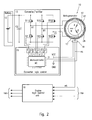
Fig. 1 is a block scheme of the integrated phasing system according to the invention; -
Fig. 2 is an electric scheme of the electric machine and electronic converter, with related logic control unit; it is further shown the shared use of the HS signal, supplied by the Hall sensor, between the logic control units of the phasing system; -
Fig. 3 is a perspective view of the rotor of the electric machine, integrated with a toothed wheel as position sensor; -
Figures 4 show two different conditions of an active Hall sensor, in relation to different positions of the toothed wheel;e 5 -
Fig. 6 is a graphic suitable to show both the switching status, and the electric shape of Hall sensor output signals; -
Fig. 7 shows a vectorial diagram of the switching sequences of phase windings of the electric machine; -
Fig. 8 is an illustrative graphic of phase activation sequences of the electric machine when running as a motor, in PWM mode, referred to the switching sequence of the phase windings; -
Fig. 9 shows a flow diagram of software algorithm used in the converter control unit. - The general features of control and phasing system according to the invention and one of its preferred embodiments shall be described in better details with reference to
Figures 1 ,2 and3 . - As initially stated, the invention can be applied in a hybrid vehicle using a series configuration, in which an electric storage battery is used to feed one or more electric drive motors of the vehicle and other ancillary services, that must be periodically charged by a voltage generator, substantially conformed by a reversible permanent-magnet synchronous electric machine, suitable to work both in electric motor mode to start an engine, and in voltage generator mode to charge the electric battery.
- As shown in the block scheme of
Figure 1 , the system comprises a permanent-magnet synchronouselectric machine 10, for example a brushless DC three-phase machine, more simply referred to as motogenerator, suitable to operate both in motor mode to start anengine 11, and in voltage generator mode to charge anelectric storage battery 12, after starting of the engine. - As widely shown in
Figure 2 , the three-phase windings A, B e C in the stator ST of themotogenerator 10, are connected to thebattery 12 by anelectronic converter 13; on its turn the rotor RT of themotogenerator 10 is operatively connected to theoutput shaft 14 of theengine 11,Figure 1 , usually consisting of a limited displacement four-stroke single-cylinder engine, e.g. with displacement comprised between 50 and 150 cubic centimetres, or slightly higher, suitable for the foreseen application. - With reference again to
Figure 1 , theconverter 13, in both operative modes of themotogenerator 10, is controlled by alogic unit 15, while the ignition circuit of theengine 11 in turn is controlled by a relatedelectronic unit 16, of any well-known type. - According to the present invention, the system comprises also a sensor for detecting the angular position of the rotor RT of the
motogenerator 10, schematically represented inFigure 1 by atoothed wheel 17 connected to thedrive shaft 14, and by an activetype Hall sensor 18, positioned outside the rotor RT, as described further on. - The
toothed wheel 17 comprises a first magnetic circuit provided by a plurality of protruding tooth or pole pieces angularly spaced apart by a constant pitch, while theHall sensor 18 comprises a second magnetic circuit linked to the previous magnetic circuit of thetoothed wheel 17, to generate a magnetic flux and to detect the reluctance and flux changes caused by the passage of the teeth of thewheel 17, and to output a signal sequence sent to related inlets of both control units 15e 16. More precisely, an outlet U1 for the signals ofHall sensor 18 is connected to asignal inlet 11 ofcontrol unit 15, respectively to a signal inlet I2 ofcontrol unit 16. - An electric solution of the
motogenerator 10,converter 13,logic control unit 15, the position sensor conformed by thetoothed wheel 17 and theHall sensor 18, shall be now described with reference toFigure 2 , where the same reference numbers ofFigure 1 are used for indicating similar or equivalent parts. - The DC/
AC power converter 13 coverts the direct voltage supplied by theelectric battery 12 into an alternated voltage to feed in sequence the three-phase windings A, B e C of themotogenerator 10 when running in motor mode, under the control oflogic unit 15. - Referring to the described case, the
converter 13 comprises six transistors S1-S6, e.g. six field effect transistors, MOSFET, that are used as switching elements for feeding voltages to the three-phase windings A, B e C. - The six transistors S1-S6 are connected with one another according to a three-phase bridge configuration, comprising three branches A1, B1 and C1, in which the terminals on the DC side of the
converter 13 are connected to a capacitor C2 in parallel to thebattery 12. Theconverter 13 on the AC side comprises further three terminals, each connected to a related phase winding of themotogenerator 10. - On its turn the
Hall sensor 18 comprises a first terminal fed with a VCC voltage, a second ground terminal GND and a third terminal HS for transmitting signals both to the inlet I1 of microcontroller MC of thecontrol unit 15, and to theinlet 12 of thecontrol unit 16. - In
Figure 2 , thereference 17 shows again the toothed wheel of the position sensor, while thereference 28 schematically shows the permanent-magnets of rotor RT of themotogenerator 10. - The terminal HS of
Hall sensor 18 is further connected to thecontrol unit 16 that, as shown by 16A, receives at the inlet side data and control parameters of the engine, such as the engine temperature, the external temperature and pressure, lambda probe signal, and other parameters, emitting at theoutlet 16B phase signals for the ignition circuit, the fuel injection and timing of the engine idling speed. - With reference again to the circuit in
Figure 2 , it can be seen that each couple of transistors S1-S6 of theconverter 13 has its control terminals connected to driver circuits D1, D2 e D3, piloted by the microcontroller MC that controls the whole system. - The
Figure 3 shows a particular integrated solution of thetoothed wheel 17 and rotor RT of themotogenerator 10. As previously stated, a permanent-magnet synchronous electric machine, suitable to operate both in motor mode and in voltage generator mode, is substantially conformed by a stator ST, shown schematically inFigure 2 , on which three star connected phase windings A, B, C are wound, and by a permanent-magnet rotor RT, arranged peripherically around the stator ST. - In detail, the rotor RT is conformed by a cup-shaped hollow body, having a
bottom wall 25 provided with ahub 26 to be connected to a drive shaft, e.g. theoutput shaft 14 ofengine 11. The cup-shaped rotor RT further comprises acylindrical wall 27 provided to surround peripherically the stator ST ofmotogenerator 10. - The interior side of
peripheral rotor wall 27 supports in a fixed manner a plurality of permanent-magnets 28, angularly spaced apart with one another by a constant pitch, which are alternatively polarized radially with opposite polarities N and S, to provide a mainmagnetic circuit 29. - The
peripheral wall 27 of the rotor RT is further conformed with a plurality ofexternal teeth 30 that, together with asame rotor wall 27, define the pole pieces of an auxiliary magnetic circuit linked to a magnetic circuit ofHall sensor 18, as it is explained below. - To correctly piloting of the
motogenerator 10, according to the example shown, it is necessary that the tooth number oftoothed wheel 17 fulfils the following relationship:
where p is again the number of pole pairs of rotor RT. Further, as shown always inFigure 3 , one of teeth of thewheel 17, inposition 30A, is removed to create a void with the aim of solving some control problems both formotogenerator 10 andengine 11, using the signals generated by theHall sensor 18 to supply both an angular reference signal for the rotor RT, and the timing of theengine 11. - According to the present invention, the
Hall sensor 18 is indicated as "active", as it comprises a magnetic circuit suitable to generate a flux linked to the magnetic circuit of thetoothed wheel 17, to detect the changes of the magnetic reluctance caused by the passage of theteeth 30; therefore, theHall sensor 18 is provided with an electronic circuit suitable to supply a digital signal co-related to the rotation speed of rotor RT, at the outlet HS, and further co-related to the position of FR magnetic field of the same rotor RT with respect to the magnetic field of the stator ST. - The position sensor comprises, in addition to the
toothed wheel 17, asingle Hall element 18 connected to an electric circuit that switches high and low in response to magnetic signals generated by the rotation of the toothed wheel. A Hall sensor suitable for a similar use can be e.g. of the type sold by the United States Company Allegro MicroSystem Inc., designed by Part. No. ATS665, or ATS674. - In short, as schematically shown in
Figures 4 and 5 , an "active" Hall effect sensor comprises aHall element 31 in a magnetic field generated by a permanent-magnet 32 faced toteeth 30 of thetoothed wheel 17; theHall element 31 forms part of anelectronic circuit 33 suitable to convert the changes of the magnetic flux into electric signals and to supply digital signals of high and low level on its outlet terminal HS, when atooth 30 and a void 30B of thetoothed wheel 17 crosses said magnetic field. - The
Figure 6 shows the shape of electric signals "Vout" at the outlet HS of position sensor, according to a situation in which atooth 30 of thetoothed wheel 17,Figure 4 , or avoid space 30B between contiguous teeth, as shown inFigure 5 , is facing theHall element 31. - The working of the control and piloting system of the
motogenerator 10 shall be now described with reference to the remaining figures. - During the running as motor mode, it is necessary to establish the correct switching instant of phase windings A, B e C,
Figure 7 , using the singleHall effect sensor 18 positioned externally in front of the rotor RT. - In order the piloting of
motor 10 correctly occurs, it is necessary that the number of pole pieces orteeth 30 of thetoothed wheel 17 satisfies the previously indicated relationship 2:
in which p is always the number of pole pairs of the motor, and thenumber 6, in the case of a three-phase synchronous machine, are the possible states ofconverter 13 as shown by E1-E6 at the line E inFigure 8 , in which there are shown the flowing directions of currents I and the corresponding field vector E1-E6 obtained feeding contemporaneously two sole phases. - Providing a correct phasing among the
magnets 28 of rotor RT and theexternal Hall sensor 18, this last generates the square-wave signal "Vout" inFigure 6 , whose rising or descending ramps coincide with the ones generated by the combination of a usual Hall system including three internal probes. - The system comprising the
toothed wheel 17 and related externalactive Hall sensor 18 is then suitable to perfectly replace the usual three internal Hall probes, both when the motogenerator 10 runs at constant speed, and when the speed is variable, as e.g. in start-up transient period or under mechanical load changes; yet this is true only if themotogenerator 10 was correctly positioned at the start-up phase. - In fact the signal, supplied by the
single Hall sensor 18 when themotogenerator 10 is standstill, does not supply any information of the initial rotor position that on the contrary is well-known by using the three internal probes. The solution of this problem is to force the rotor RT to be brought to an initial position known a priori; this is obtained by feeding with a pre-established configuration, two phases of themotogenerator 10 and awaiting that rotor RT reaches the required start position shown by P1 inFigure 7 . - In this situation the rotor turns of a maximum angle that is given by the following formula:

the angle αMAX is lower in machines having many poles. - As the rotation of the rotor RT, during each start-up, can occur in an arbitrary manner into clockwise or anticlockwise direction, it is important to estimate the angle αMAX, above all in applications in which a reverse rotation, also of little angles, can became harmful.
- When the rotor is aligned to the pre-established start position, it is possible to act in analogous manner for a conventional drive having three internal probes, or piloting the
converter 13 with the same configurations ofFigure 8 , a pair of phase winding are cyclically powered, in sequence, for the generation of the rotational magnetic field of stator ST, suitable to drive the rotor RT in the desired rotational direction. - The optimal instant to switch the feeding of the phases, in this case is provided by any rising or descending ramp, according to the system works with positive or negative logic of the square-wave signal supplied by external Hall sensor, as shown by HS in
Figure 8 . - To allow a correct working of this system, it is necessary that at start-up, in the initial positioning phase P1, the torque developed by the
motogenerator 10 working in motor mode is sufficient to move the rotor RT, so that its field vector coincides with position P1. Differently, as thecontrol logic 15 at start-up considers the rotor RT always as being in position P1, the consequence is that the following operation of the piloting sequence is no more correct: in this situation the motogenerator 10 can remain locked or, if it can turn, it develops a very low drive torque, that could not be sufficient to exceed an eventual increment of applied load. - For obtaining that the rotor RT reaches the start-up position P1 the first piloting sequence must be applied during a certain time interval Δt1, included between the instant t1 at which the voltage is applied to the
motogenerator 10 and the instant t2 at which the second piloting sequence, corresponding to position P2 inFigure 7 is activated. The time interval Δt1 must be established by experimental tests, evaluating if the selected value is also suitable in the worse condition, that is to say when the rotor is positioned in the farthest point starting from the start-up position P1, and when the resisting torque is maximum at low revolutions number. It is difficult to forecast theoretically the maximum positioning time, as it must considered that the rotor RT, before being stabilized in the position P1, can swing many times around this position owing to the mechanical inertia of the rotor mass; further this initial phase can suffer the influence of other factors, such as voltage and load changes, or other ones. - Nevertheless it can occur that the rotor RT being in a particularly unfavourable start position cannot reach the point P1: denoting by θ the angle between the magnetic field vector of the rotor and the field vector of the stator, when θ=180° the motor torque is zero. For avoiding these problems, after having activated the position P1 during a time Δt1, the switching to the position P2 in
Figure 7 is made, keeping it active during a certain time interval Δt2, this also being necessarily established by experimental tests, but in any case having a length shorter than Δt1. In this manner if the rotor does not reach the position P1, it can directly turn in all cases to the position P2, as in this case θ is different from 180°. - The time interval Δt2 is comprised between the instant t2 already defined, and the instant t3 in which the third piloting sequence, position P3 in
Figure 7 is activated. Passing the rotor RT from position P2 to position P3, theHall sensor 18 generates the square-wave signal HS ofFigure 8 , by which it is possible to use the first valid wave ramp to activate the following switching E3, while the preceding wave ramps of signal HS are ignored by thecontrol logic 15; then the cycle goes on by cyclically activating, in sequence, the configuration rows E inFigure 8 . - Further this strategy allows the setting of Hall sensor 18: in fact each time in which the
electronic circuit 33 of thesensor 18 is activated, some internal parameters must be set to detect the difference of the magnetic flux intensity when the sensors faced to atooth 30 and to avoid space 30B respectively, and consequently to generate the right electric output signal as shown inFigure 6 . For making this operation, it is sufficient to turn the rotor of an angle suitable to cause at least atooth 30 and avoid space 30B exceed thesensor 18; therefore during this setting operation, the first two ramps of the square-wave signal cannot be used to synchronize the switchings. Therefore thesensor 18 can make the above mentioned setting during the positioning phases P1 and P2, in which the ramps of square-wave signal are ignored. - During the positioning in P1 or P2, in which the rotor is locked, it is necessary to limit the current by establishing the duty cycle value of the PWM signal that pilots the transistors of the
converter 13. This parameter that is also established experimentally, in general differs from the one associated to the PWM signal used for modulating the power delivered by themotogenerator 10. - Now it is possible to establish the advantages of a system having an external Hall probe and a toothed wheel in the case in which the
motogenerator 10 is operatively connected to anengine 11. - In the considered case, the
engine 11 is of four-stroke, single-cylinder, little displacement, type; therefore it is necessary to be able to modulate the delivered power and, at the same time, to minimize the fuel consumptions and the harmful emissions in any work condition. For this aim the engine is controlled, in a well-known manner, by aspecific control unit 16, that has the aim to time in a precise manner all of so-called phased events, such as e.g.: the spark ignition instant, the coil charging duration for the ignition, the opening instant of engine gasoline injectors, the monitoring of the lambda probe, temperature and for pressure sensors. - Then the
control unit 11 requires a signal that indicates the piston position inside the cylinder: in automotive field it is widely diffused the use of an inductive sensor, usually said pick-up sensor, that allows to get a pulse signal filtered by a clipping electronic circuit to provide a square wave. But a pick-up device is a passive sensor that does not require external feeding; further, as the pick-up uses the passage of a tooth to generate a pulse, it cannot supply an appreciable signal when the toothed wheel turns at low speed, generally lower than 100 r.p.m.. - Further the
control unit 16 must receive information related to the absolute phase of the engine, that is to say it must recognize a condition which corresponds to a well-known position of the piston. To this regard according to the invention a toothed wheel is used having an established number of equidistant teeth D, some of which H being removed to provide a void space greater than the space existing between the teeth; in a typical toothed wheel used in automotive field: D=24 e H=2. - Considering the assembly comprising the
motogenerator 10 andengine 11, considering further that anactive Hall sensor 18 operates also in a static condition of the system, it can be observed that the control and piloting system according to this invention allows to get a further advantage, including the replacement of conventional toothed wheel and pick-up system, that in any case is necessary to control the engine, with the same position sensor comprising the modifiedtoothed wheel 17 and an activeexternal Hall sensor 18 used to pilot themotogenerator 10; all these advantages can be obtained with reduced costs and better reliability with respect to conventional solutions. - Therefore, according to the invention, the
toothed wheel 17 andexternal Hall sensor 18 have a double function: the first one is to provide the correct switching instant of the phases A, B and C to pilot themotogenerator 10 at the start-up of theengine 11, the second one includes the synchronization of all of phased events of the same engine. - Now it shall be described the problematic technical aspects and a possible compromise to apply the system according to the invention for an assembly comprising the
motogenerator 10 and theengine 11. - The signal generated by
Hall sensor 18 is used by bothcontrol units - As it would be too much expensive to use two separate toothed wheels, one for the motogenerator 10 and the other one for the
engine 11, according to a particular feature of the invention, as shown inFigure 3 , it is obtained a valid integrated solution by the use of a sole toothed wheel provided on the external wall surface of the rotor RT of themotogenerator 10. Considering the example of an electric three-phase machine, the number of equispaced teeth must be equal to six times the number of pole pairs of motogenerator, D=6xp, but a tooth is removed, as shown, inposition 30A inFigure 3 , for being able to establish the absolute phase of the engine. - This compromise affects the correct control of the whole system in a very negligible manner, as the further complications introduced by the use of a sole toothed wheel can be solved by suitable software algorithms stored in the two
control units - For example, considering a
motogenerator 10 having fourteen poles, in which p=7; it must be provided atoothed wheel 17 with 7x6=42 equidistant teeth, and must be eliminated at least one tooth, then thetoothed wheel 17 shall have D=42-1 teeth. - In the case of a polyphase machine, the number of teeth D is given by:

where "p" is always the pole pair number of the machine and "n" is the phase number. For example in a pentaphase machine with 16 poles the tooth number D is:
- As for the control software of the engine, the change from the classic toothed wheel with D=24-2 to the toothed wheel with D=42-1 causes a greater critical condition in the control of time events synchronized with the same toothed wheel. For causing these events with the toothed wheel in which D=42-1 a time interval is disposable that is about one half the time of a conventional toothed wheel; further, the void space being of a
sole tooth 30A, instead of two teeth; this increases the probability that the absolute engine phase is not correctly established. - The first problem is solved by reducing the execution times of software algorithms correlated to the
toothed wheel 17, while the second problem is solved by selecting in a more accurate manner the time parameters that allow the software to sense thevoid space 30A corresponding to the removed tooth. - As previously stated, the passage from an ideal wheel with 42 teeth to a wheel with a number of teeth D=42-1 introduces some problems related to the absence of a tooth for the software of the
unit 15, that controls theconverter 13. In fact, when the Hall sensor is opposed to thevoid space 30A, it generates an output square-wave signal, in which a positive front and a negative front related to the removed tooth are lacking; as for the correct piloting of themotogenerator 10 it is not possible to omit any switching, it is necessary to adapt the software of thecontrol unit 15 to the new features of the signal generated byHall sensor 18. - For solving this problem it is important to note that the position of the
void space 30A is well-known in the range of 360 electric degrees: considering the case of a sole lacking tooth, it can be established experimentally which field vector of piloting sequence E1-E6 is related to the void space between the teeth, due to the removed tooth, e.g. the phase E6 inFigure 8 , corresponding to the position P2 inFigure 7 . - At this point, before the passage of the
void space 30A caused by the lacking tooth, it is sufficient to activate a peripheral timer of the microcontroller MC in thecontrol unit 15 for theconverter 13, which, after a time At forces the successive switching also in absence of a signal wave ramp generated by the Hall sensor. The parameter Δt is equal to the time elapsing between two preceding switchings. Obviously this requires an approximation, but the involved error is completely negligible as the rotor speed, in correspondence with thevoid space 30A, changes limitedly also during the start-up transient period. - In an electric machine with a number of pole pairs p more than 1, the switching that could occur in correspondence of the
void space 30A related to the lacking tooth, occurs "p" times for each complete revolution of rotor RT, while the void space occurs one sole time per revolution of the toothed wheel. - Then the control software of
unit 15 must be suitable to detect the position ofvoid space 30A, corresponding to detection of the absolute phase of engine, to generate a number of time parameters. This operation must be possibly made within the first complete revolution of the rotor RT, so that, in the successive revolutions, one virtual switching only is activated using the timer, with respect to a total of 6 x p switchings for each revolution. - The flow diagram in
Figure 9 , descriptive of the control algorithm, shall be shortly discussed in the following, making reference toFigures 3 ,7 and8 . - At the activation of initial position P1, in which S5 is in ON state, and S4 in PWM mode, after an initial time Δt1, as previously stated, the following position P2 it is activated, in which S1 is ON, while S6 is in PWM mode, for a time Δt2. At this moment the position P3 is activated, coincident with the position E2, in which S3 is ON and S2 is in PWM mode.
- If a negative wave ramp of the signal emitted by Hall probe is detected, SI, the cycle activates the position E3 in which S5 is ON and S2 is in PWM mode.
- As shown in
Figure 9 , the routine goes on until the activation of the position E6, at the instant t1, in which S1 in ON and S6 is in PWM; when the negative ramp of the signal generated by the Hall probe is again detected, the position E1 is activated, at the instant t2 in which S3 in ON and S6 is in PWM mode. - At this time, if the absolute phase was not established or, in the case in which it is known, and it is forecast to find the
void space 30A for the following switching, the timer of microcontroller MC is activated and the time counting Δt=t2-t1 is set up; at the end of the time interval Δt, the position E2 in reactivated. - Otherwise, if the absolute phase has been established and it is not forecast to find the
void space 30A in the successive switching, a negative ramp in the Hall sensor signal is detected, SI, and the position E2 is again activated. The cycle is repeated for a time necessary to start the engine. - Once the engine is started under the control of the
logic unit 16, thecontrol unit 15 switches the transistors S1-S6 ofconverter 13 into rectifier mode, allowing to charge thebattery 12. - Considering what said and shown in annexed drawings, it shall be understood that an integrated control system for a voltage generator and engine assembly, and related method have been provided, all of which being suitable to obtain the specified objects; therefore other modifications or changes can be made to the system and related control method, without departing from the following claims.
Claims (10)
- An integrated phasing system for an assembly comprising a synchronous electric machine (10) of permanent magnet type and an engine (11), in which the electric machine (10) comprises a stator (ST) having phase windings (A, B, C) and a rotor (RT) provided with a plurality of permanent-magnets (28), operatively connected to said engine (11), and electronic control means (13, 15) conformed to initially operate in motor mode the electric machine (10) at the start of the engine (11), and subsequently to operate in voltage generator mode for charging an electric battery (12), in which the electronic control means comprises:- a converter (13) connected between the battery (12) and the phase windings (A, B, C) of the electric machine (10);- a first logic control unit (15) for controlling the converter (13);- a second control unit (16) for controlling the engine (11); and- an angular position sensor (18) for providing the first control unit (15) with control signals indicative of the angular position of the rotor (RT) of the electric machine (10);characterized in that the angular position sensor (18) comprises:- a toothed wheel (17) operatively connected to the electric machine (10) and the engine (11), the toothed wheel (17) being conformed with a first magnetic circuit having a plurality of angularly spaced apart pole pieces (30);- an external Hall probe (18) facing the toothed wheel (17), the Hall sensor (18) comprising a second active magnetic circuit (32) to generate a magnetic flux linked to the first magnetic circuit (30) of the toothed wheel (17), said Hall sensor (18) being conformed and arranged to generate and supply both the first and second control units (15, 16) with a sequence of piloting and timing signals in relation to reluctance changes of the Hall probe (18) caused by the rotation of the toothed wheel (17).
- The integrated phasing system according to claim 1, in which the rotor (RT) of the electric machine (10) comprises a cup-shaped body having a peripheral wall (27) which surrounds the stator (ST), characterized in that the toothed wheel (17) is provided externally onto the peripheral wall (27) of the rotor (RT).
- The integrated phasing system according to claim 1, characterized in that, the toothed wheel (17) in at least one angular position comprises a void space (30A) extending for an angle greater than the angle of the void space between contiguous tooth (30) of the toothed wheel (17), and in that the first logic control unit (15) comprises a microprocessor (MC) and a timing unit programmed to cause a forced switching of the phase windings (A, B, C) of the electric machines (10) in correspondence with said greater void space (30A).
- A method for piloting an electric machine (10) and for timing phased events of an engine (11) operatively connected to the electric machine (10), by the integrated phasing system according to claim 1, characterized by the steps of:- forcing the rotor (RT) of electric machine (10) to stably reach a pre-established start position (P1; P2) by feeding two respective phase windings (A, B, C) of the electric machine (10); and- generating subsequently a sequence of pilot signals for the electric machine (10) by cyclically powering, each time, a different pair of phase windings (A, B, C) of the electric machine (10).
- The method according to claim 4, characterized by feeding the pairs of phase windings (A, B, C) of electric machine (10) for a time interval (Δt1) necessary to allow the rotor (RT) to reach a first start position (P1).
- The method according to claim 5, characterized in that, keeping a zero drive torque in the first start position (P1), a subsequent switching of the phase windings (A, B, C) is performed for a time interval (Δt2) shorter than the previous time interval (Δt1), for positioning the rotor (RT) in a second angular start position (P2).
- The method according to claim 5, characterized by forcing the rotor (RT) to reach a stabilized condition in the first start position (P1) causing the rotor (RT) to rotate of a maximum angle given by the relation:

where p is the pole pair of the electric machine (10). - The method according to claim 4, characterized by conforming the toothed wheel (17) of the position sensor (18), in an angular position, with a void space (30A) greater than the void space between contiguous tooth (30) to provide a control signal co-related to an absolute phase of the engine (11) and/or electric machine (10); generating by the Hall sensor (18) a square wave control signal (HS) having no wave ramp in correspondence of said greater void space (30A) of the toothed wheel (17); and causing by said first control unit (15) a phase winding switching, in relation to said lacking wave ramp, after a time interval (At) corresponding to the time elapsed between two previous switching steps.
- The method according to claim 8, characterized by feeding the phase windings (A, B, C) of the electric machine (10) for a time lenght (Δt1) between an instant in which the voltage is supplied to the electric machine (10), and an instant in which a first pilot switching of the phase windings (A, B, C) is carried out for positioning the rotor (RT) in the first start position (P1) and, in the event of zero torque feeding the phase windings (A, B, C) for a time interval (Δt2) shorter than the previous one (Δt1), included between the first pilot switching and a second pilot switching to position the rotor (RT) in a second start position (P2).
- The method according to claim 4, characterized by limiting the current value absorbed by the phase windings (A, B, C), during the positioning of rotor (RT) in the first and/or second start position (P1, P2) by modulating in PWM the control signal supplied to the converter (13).
Applications Claiming Priority (1)
| Application Number | Priority Date | Filing Date | Title |
|---|---|---|---|
| ITMI2008A001420A IT1391650B1 (en) | 2008-07-30 | 2008-07-30 | INTEGRATED TIMING SYSTEM FOR SYNCHRONOUS ELECTRIC MACHINE COMBINED WITH ENDOTHERMAL MOTOR AND RELATIVE METHOD |
Publications (2)
| Publication Number | Publication Date |
|---|---|
| EP2149975A1 true EP2149975A1 (en) | 2010-02-03 |
| EP2149975B1 EP2149975B1 (en) | 2014-08-13 |
Family
ID=40758695
Family Applications (1)
| Application Number | Title | Priority Date | Filing Date |
|---|---|---|---|
| EP20090007813 Active EP2149975B1 (en) | 2008-07-30 | 2009-06-15 | Method and integrated phasing system for a synchronous electric machine and engine assembly |
Country Status (2)
| Country | Link |
|---|---|
| EP (1) | EP2149975B1 (en) |
| IT (1) | IT1391650B1 (en) |
Cited By (4)
| Publication number | Priority date | Publication date | Assignee | Title |
|---|---|---|---|---|
| CN102744724A (en) * | 2011-04-18 | 2012-10-24 | 库卡罗伯特有限公司 | Machine with relative rotatable members |
| WO2016016812A1 (en) * | 2014-08-01 | 2016-02-04 | Piaggio & C. S.P.A. | Permanent magnet electric motor for an internal combustion engine and related starting control system |
| RU2574217C2 (en) * | 2013-11-06 | 2016-02-10 | Федеральное государственное бюджетное образовательное учреждение высшего профессионального образования "Псковский государственный университет" | Starter-generator set for self-contained power supply based on rotary-vane engine with external heat supply and method of its usage |
| CN112953124A (en) * | 2019-11-26 | 2021-06-11 | 昆山为涵电驱动科技有限公司 | Integrated control device, starting and starting integrated motor system and integrated control method thereof |
Citations (6)
| Publication number | Priority date | Publication date | Assignee | Title |
|---|---|---|---|---|
| US5065086A (en) | 1988-04-19 | 1991-11-12 | Shinko Electric Co., Ltd. | Engine driven generator |
| EP1138539A2 (en) | 2000-03-29 | 2001-10-04 | Kabushiki Kaisha Toshiba | Control device for permanent magnet motor serving as both engine starter and generator in motor vehicle |
| EP1396629A2 (en) * | 2002-09-05 | 2004-03-10 | Honda Giken Kogyo Kabushiki Kaisha | Rotation Detecting Apparatus |
| US20040153235A1 (en) * | 2003-01-28 | 2004-08-05 | Toyota Jidosha Kabushiki Kaisha | Stop position estimating apparatus of internal combustion engine |
| US20060152388A1 (en) * | 2005-01-12 | 2006-07-13 | Bertrand Legrand | Position sensor with unbalanced cyclic ratio |
| WO2006090890A1 (en) * | 2005-02-25 | 2006-08-31 | Toyota Jidosha Kabushiki Kaisha | Apparatus and method for controlling internal combustion engine |
-
2008
- 2008-07-30 IT ITMI2008A001420A patent/IT1391650B1/en active
-
2009
- 2009-06-15 EP EP20090007813 patent/EP2149975B1/en active Active
Patent Citations (6)
| Publication number | Priority date | Publication date | Assignee | Title |
|---|---|---|---|---|
| US5065086A (en) | 1988-04-19 | 1991-11-12 | Shinko Electric Co., Ltd. | Engine driven generator |
| EP1138539A2 (en) | 2000-03-29 | 2001-10-04 | Kabushiki Kaisha Toshiba | Control device for permanent magnet motor serving as both engine starter and generator in motor vehicle |
| EP1396629A2 (en) * | 2002-09-05 | 2004-03-10 | Honda Giken Kogyo Kabushiki Kaisha | Rotation Detecting Apparatus |
| US20040153235A1 (en) * | 2003-01-28 | 2004-08-05 | Toyota Jidosha Kabushiki Kaisha | Stop position estimating apparatus of internal combustion engine |
| US20060152388A1 (en) * | 2005-01-12 | 2006-07-13 | Bertrand Legrand | Position sensor with unbalanced cyclic ratio |
| WO2006090890A1 (en) * | 2005-02-25 | 2006-08-31 | Toyota Jidosha Kabushiki Kaisha | Apparatus and method for controlling internal combustion engine |
Cited By (8)
| Publication number | Priority date | Publication date | Assignee | Title |
|---|---|---|---|---|
| CN102744724A (en) * | 2011-04-18 | 2012-10-24 | 库卡罗伯特有限公司 | Machine with relative rotatable members |
| CN102744724B (en) * | 2011-04-18 | 2016-01-06 | 库卡罗伯特有限公司 | There is the machine of the segmental appendage that can relatively rotate with respect to each other |
| RU2574217C2 (en) * | 2013-11-06 | 2016-02-10 | Федеральное государственное бюджетное образовательное учреждение высшего профессионального образования "Псковский государственный университет" | Starter-generator set for self-contained power supply based on rotary-vane engine with external heat supply and method of its usage |
| WO2016016812A1 (en) * | 2014-08-01 | 2016-02-04 | Piaggio & C. S.P.A. | Permanent magnet electric motor for an internal combustion engine and related starting control system |
| CN106574596A (en) * | 2014-08-01 | 2017-04-19 | 比亚乔及C.股份公司 | Permanent magnet electric motor for an internal combustion engine and related starting control system |
| US10233887B2 (en) | 2014-08-01 | 2019-03-19 | Piaggio & C. S.P.A. | Permanent magnet electric motor for an internal combustion engine and related starting control system |
| CN106574596B (en) * | 2014-08-01 | 2021-02-19 | 比亚乔及C.股份公司 | Permanent magnet motor for internal combustion engine and related starting control system |
| CN112953124A (en) * | 2019-11-26 | 2021-06-11 | 昆山为涵电驱动科技有限公司 | Integrated control device, starting and starting integrated motor system and integrated control method thereof |
Also Published As
| Publication number | Publication date |
|---|---|
| IT1391650B1 (en) | 2012-01-17 |
| EP2149975B1 (en) | 2014-08-13 |
| ITMI20081420A1 (en) | 2010-01-31 |
Similar Documents
| Publication | Publication Date | Title |
|---|---|---|
| CN101647190B (en) | Brushless motor control device and brushless motor controlling method | |
| US7081738B2 (en) | Generating device having magneto generator | |
| EP2701300B1 (en) | Motor control system, motor control device and brushless motor | |
| CN105874189B (en) | Engine unit and vehicle | |
| JP2000209891A (en) | Starter generator for internal combustion engine | |
| JPWO2015041321A1 (en) | 3-phase brushless motor drive device | |
| JP2001128484A (en) | Detection position correction method of synchronous motor | |
| CN104104285A (en) | Control device for vehicle generator-motor and control method therefor | |
| US6699081B1 (en) | Marine propulsion device with a switched reluctance starter motor and generator system | |
| EP2149975B1 (en) | Method and integrated phasing system for a synchronous electric machine and engine assembly | |
| US9777605B2 (en) | Motor control apparatus | |
| JP3700106B2 (en) | Sensorless switched reluctance motor drive circuit | |
| EP3414450B1 (en) | Method and system for controlling an integrated starter-generator | |
| US10756661B2 (en) | Field winding type rotating electric machine | |
| JP4196637B2 (en) | Internal combustion engine drive power generator | |
| JP2009524390A (en) | Reversible multiphase electric rotating machine and control method thereof | |
| EP3823155B1 (en) | Drive device for three-phase rotating electric machine and three-phase rotating electric machine unit | |
| JP3393366B2 (en) | Device and method for detecting rotor position of sensorless motor | |
| JP2002186293A (en) | Control device of dynamo-electric machine for internal combustion engine | |
| EP3414449B1 (en) | Method and system for cranking an internal combustion engine | |
| JP2001069797A (en) | Current-adjusting device of starter generator | |
| JP6967880B2 (en) | Electronic control device | |
| JP3596459B2 (en) | Starter generator for internal combustion engine | |
| JP6948845B2 (en) | Electronic control device | |
| JP2683653B2 (en) | Engine torque control device |
Legal Events
| Date | Code | Title | Description |
|---|---|---|---|
| PUAI | Public reference made under article 153(3) epc to a published international application that has entered the european phase |
Free format text: ORIGINAL CODE: 0009012 |
|
| AK | Designated contracting states |
Kind code of ref document: A1 Designated state(s): AT BE BG CH CY CZ DE DK EE ES FI FR GB GR HR HU IE IS IT LI LT LU LV MC MK MT NL NO PL PT RO SE SI SK TR |
|
| AX | Request for extension of the european patent |
Extension state: AL BA RS |
|
| 17P | Request for examination filed |
Effective date: 20100330 |
|
| 17Q | First examination report despatched |
Effective date: 20100701 |
|
| RIC1 | Information provided on ipc code assigned before grant |
Ipc: F02P 7/07 20060101ALI20131108BHEP Ipc: H02P 6/14 20060101AFI20131108BHEP Ipc: F02N 11/04 20060101ALI20131108BHEP Ipc: F02D 41/00 20060101ALI20131108BHEP |
|
| GRAP | Despatch of communication of intention to grant a patent |
Free format text: ORIGINAL CODE: EPIDOSNIGR1 |
|
| INTG | Intention to grant announced |
Effective date: 20140116 |
|
| GRAS | Grant fee paid |
Free format text: ORIGINAL CODE: EPIDOSNIGR3 |
|
| GRAA | (expected) grant |
Free format text: ORIGINAL CODE: 0009210 |
|
| AK | Designated contracting states |
Kind code of ref document: B1 Designated state(s): AT BE BG CH CY CZ DE DK EE ES FI FR GB GR HR HU IE IS IT LI LT LU LV MC MK MT NL NO PL PT RO SE SI SK TR |
|
| REG | Reference to a national code |
Ref country code: GB Ref legal event code: FG4D |
|
| REG | Reference to a national code |
Ref country code: AT Ref legal event code: REF Ref document number: 682725 Country of ref document: AT Kind code of ref document: T Effective date: 20140815 Ref country code: CH Ref legal event code: EP |
|
| REG | Reference to a national code |
Ref country code: IE Ref legal event code: FG4D |
|
| REG | Reference to a national code |
Ref country code: DE Ref legal event code: R096 Ref document number: 602009025883 Country of ref document: DE Effective date: 20140918 |
|
| REG | Reference to a national code |
Ref country code: NL Ref legal event code: VDEP Effective date: 20140813 |
|
| REG | Reference to a national code |
Ref country code: AT Ref legal event code: MK05 Ref document number: 682725 Country of ref document: AT Kind code of ref document: T Effective date: 20140813 |
|
| REG | Reference to a national code |
Ref country code: LT Ref legal event code: MG4D |
|
| PG25 | Lapsed in a contracting state [announced via postgrant information from national office to epo] |
Ref country code: NO Free format text: LAPSE BECAUSE OF FAILURE TO SUBMIT A TRANSLATION OF THE DESCRIPTION OR TO PAY THE FEE WITHIN THE PRESCRIBED TIME-LIMIT Effective date: 20141113 Ref country code: GR Free format text: LAPSE BECAUSE OF FAILURE TO SUBMIT A TRANSLATION OF THE DESCRIPTION OR TO PAY THE FEE WITHIN THE PRESCRIBED TIME-LIMIT Effective date: 20141114 Ref country code: FI Free format text: LAPSE BECAUSE OF FAILURE TO SUBMIT A TRANSLATION OF THE DESCRIPTION OR TO PAY THE FEE WITHIN THE PRESCRIBED TIME-LIMIT Effective date: 20140813 Ref country code: SE Free format text: LAPSE BECAUSE OF FAILURE TO SUBMIT A TRANSLATION OF THE DESCRIPTION OR TO PAY THE FEE WITHIN THE PRESCRIBED TIME-LIMIT Effective date: 20140813 Ref country code: PT Free format text: LAPSE BECAUSE OF FAILURE TO SUBMIT A TRANSLATION OF THE DESCRIPTION OR TO PAY THE FEE WITHIN THE PRESCRIBED TIME-LIMIT Effective date: 20141215 Ref country code: ES Free format text: LAPSE BECAUSE OF FAILURE TO SUBMIT A TRANSLATION OF THE DESCRIPTION OR TO PAY THE FEE WITHIN THE PRESCRIBED TIME-LIMIT Effective date: 20140813 Ref country code: LT Free format text: LAPSE BECAUSE OF FAILURE TO SUBMIT A TRANSLATION OF THE DESCRIPTION OR TO PAY THE FEE WITHIN THE PRESCRIBED TIME-LIMIT Effective date: 20140813 Ref country code: BG Free format text: LAPSE BECAUSE OF FAILURE TO SUBMIT A TRANSLATION OF THE DESCRIPTION OR TO PAY THE FEE WITHIN THE PRESCRIBED TIME-LIMIT Effective date: 20141113 |
|
| PG25 | Lapsed in a contracting state [announced via postgrant information from national office to epo] |
Ref country code: HR Free format text: LAPSE BECAUSE OF FAILURE TO SUBMIT A TRANSLATION OF THE DESCRIPTION OR TO PAY THE FEE WITHIN THE PRESCRIBED TIME-LIMIT Effective date: 20140813 Ref country code: AT Free format text: LAPSE BECAUSE OF FAILURE TO SUBMIT A TRANSLATION OF THE DESCRIPTION OR TO PAY THE FEE WITHIN THE PRESCRIBED TIME-LIMIT Effective date: 20140813 Ref country code: LV Free format text: LAPSE BECAUSE OF FAILURE TO SUBMIT A TRANSLATION OF THE DESCRIPTION OR TO PAY THE FEE WITHIN THE PRESCRIBED TIME-LIMIT Effective date: 20140813 Ref country code: CY Free format text: LAPSE BECAUSE OF FAILURE TO SUBMIT A TRANSLATION OF THE DESCRIPTION OR TO PAY THE FEE WITHIN THE PRESCRIBED TIME-LIMIT Effective date: 20140813 Ref country code: IS Free format text: LAPSE BECAUSE OF FAILURE TO SUBMIT A TRANSLATION OF THE DESCRIPTION OR TO PAY THE FEE WITHIN THE PRESCRIBED TIME-LIMIT Effective date: 20141213 |
|
| PG25 | Lapsed in a contracting state [announced via postgrant information from national office to epo] |
Ref country code: NL Free format text: LAPSE BECAUSE OF FAILURE TO SUBMIT A TRANSLATION OF THE DESCRIPTION OR TO PAY THE FEE WITHIN THE PRESCRIBED TIME-LIMIT Effective date: 20140813 |
|
| PG25 | Lapsed in a contracting state [announced via postgrant information from national office to epo] |
Ref country code: DK Free format text: LAPSE BECAUSE OF FAILURE TO SUBMIT A TRANSLATION OF THE DESCRIPTION OR TO PAY THE FEE WITHIN THE PRESCRIBED TIME-LIMIT Effective date: 20140813 Ref country code: CZ Free format text: LAPSE BECAUSE OF FAILURE TO SUBMIT A TRANSLATION OF THE DESCRIPTION OR TO PAY THE FEE WITHIN THE PRESCRIBED TIME-LIMIT Effective date: 20140813 Ref country code: RO Free format text: LAPSE BECAUSE OF FAILURE TO SUBMIT A TRANSLATION OF THE DESCRIPTION OR TO PAY THE FEE WITHIN THE PRESCRIBED TIME-LIMIT Effective date: 20140813 Ref country code: SK Free format text: LAPSE BECAUSE OF FAILURE TO SUBMIT A TRANSLATION OF THE DESCRIPTION OR TO PAY THE FEE WITHIN THE PRESCRIBED TIME-LIMIT Effective date: 20140813 Ref country code: EE Free format text: LAPSE BECAUSE OF FAILURE TO SUBMIT A TRANSLATION OF THE DESCRIPTION OR TO PAY THE FEE WITHIN THE PRESCRIBED TIME-LIMIT Effective date: 20140813 |
|
| REG | Reference to a national code |
Ref country code: DE Ref legal event code: R097 Ref document number: 602009025883 Country of ref document: DE |
|
| PG25 | Lapsed in a contracting state [announced via postgrant information from national office to epo] |
Ref country code: PL Free format text: LAPSE BECAUSE OF FAILURE TO SUBMIT A TRANSLATION OF THE DESCRIPTION OR TO PAY THE FEE WITHIN THE PRESCRIBED TIME-LIMIT Effective date: 20140813 |
|
| PLBE | No opposition filed within time limit |
Free format text: ORIGINAL CODE: 0009261 |
|
| STAA | Information on the status of an ep patent application or granted ep patent |
Free format text: STATUS: NO OPPOSITION FILED WITHIN TIME LIMIT |
|
| 26N | No opposition filed |
Effective date: 20150515 |
|
| PG25 | Lapsed in a contracting state [announced via postgrant information from national office to epo] |
Ref country code: SI Free format text: LAPSE BECAUSE OF FAILURE TO SUBMIT A TRANSLATION OF THE DESCRIPTION OR TO PAY THE FEE WITHIN THE PRESCRIBED TIME-LIMIT Effective date: 20140813 |
|
| REG | Reference to a national code |
Ref country code: DE Ref legal event code: R119 Ref document number: 602009025883 Country of ref document: DE |
|
| PG25 | Lapsed in a contracting state [announced via postgrant information from national office to epo] |
Ref country code: MC Free format text: LAPSE BECAUSE OF FAILURE TO SUBMIT A TRANSLATION OF THE DESCRIPTION OR TO PAY THE FEE WITHIN THE PRESCRIBED TIME-LIMIT Effective date: 20140813 |
|
| REG | Reference to a national code |
Ref country code: CH Ref legal event code: PL |
|
| GBPC | Gb: european patent ceased through non-payment of renewal fee |
Effective date: 20150615 |
|
| PG25 | Lapsed in a contracting state [announced via postgrant information from national office to epo] |
Ref country code: LU Free format text: LAPSE BECAUSE OF FAILURE TO SUBMIT A TRANSLATION OF THE DESCRIPTION OR TO PAY THE FEE WITHIN THE PRESCRIBED TIME-LIMIT Effective date: 20150615 |
|
| REG | Reference to a national code |
Ref country code: IE Ref legal event code: MM4A |
|
| REG | Reference to a national code |
Ref country code: FR Ref legal event code: ST Effective date: 20160229 |
|
| PG25 | Lapsed in a contracting state [announced via postgrant information from national office to epo] |
Ref country code: CH Free format text: LAPSE BECAUSE OF NON-PAYMENT OF DUE FEES Effective date: 20150630 Ref country code: LI Free format text: LAPSE BECAUSE OF NON-PAYMENT OF DUE FEES Effective date: 20150630 Ref country code: IE Free format text: LAPSE BECAUSE OF NON-PAYMENT OF DUE FEES Effective date: 20150615 Ref country code: DE Free format text: LAPSE BECAUSE OF NON-PAYMENT OF DUE FEES Effective date: 20160101 Ref country code: GB Free format text: LAPSE BECAUSE OF NON-PAYMENT OF DUE FEES Effective date: 20150615 |
|
| PG25 | Lapsed in a contracting state [announced via postgrant information from national office to epo] |
Ref country code: FR Free format text: LAPSE BECAUSE OF NON-PAYMENT OF DUE FEES Effective date: 20150630 |
|
| PG25 | Lapsed in a contracting state [announced via postgrant information from national office to epo] |
Ref country code: BE Free format text: LAPSE BECAUSE OF FAILURE TO SUBMIT A TRANSLATION OF THE DESCRIPTION OR TO PAY THE FEE WITHIN THE PRESCRIBED TIME-LIMIT Effective date: 20140813 |
|
| PG25 | Lapsed in a contracting state [announced via postgrant information from national office to epo] |
Ref country code: MT Free format text: LAPSE BECAUSE OF FAILURE TO SUBMIT A TRANSLATION OF THE DESCRIPTION OR TO PAY THE FEE WITHIN THE PRESCRIBED TIME-LIMIT Effective date: 20140813 |
|
| PG25 | Lapsed in a contracting state [announced via postgrant information from national office to epo] |
Ref country code: HU Free format text: LAPSE BECAUSE OF FAILURE TO SUBMIT A TRANSLATION OF THE DESCRIPTION OR TO PAY THE FEE WITHIN THE PRESCRIBED TIME-LIMIT; INVALID AB INITIO Effective date: 20090615 |
|
| PG25 | Lapsed in a contracting state [announced via postgrant information from national office to epo] |
Ref country code: TR Free format text: LAPSE BECAUSE OF FAILURE TO SUBMIT A TRANSLATION OF THE DESCRIPTION OR TO PAY THE FEE WITHIN THE PRESCRIBED TIME-LIMIT Effective date: 20140813 |
|
| PG25 | Lapsed in a contracting state [announced via postgrant information from national office to epo] |
Ref country code: MK Free format text: LAPSE BECAUSE OF FAILURE TO SUBMIT A TRANSLATION OF THE DESCRIPTION OR TO PAY THE FEE WITHIN THE PRESCRIBED TIME-LIMIT Effective date: 20140813 |
|
| P01 | Opt-out of the competence of the unified patent court (upc) registered |
Effective date: 20230527 |
|
| PGFP | Annual fee paid to national office [announced via postgrant information from national office to epo] |
Ref country code: IT Payment date: 20230620 Year of fee payment: 15 |