EP2158854B1 - Surgical clip applier - Google Patents
Surgical clip applier Download PDFInfo
- Publication number
- EP2158854B1 EP2158854B1 EP09252053.5A EP09252053A EP2158854B1 EP 2158854 B1 EP2158854 B1 EP 2158854B1 EP 09252053 A EP09252053 A EP 09252053A EP 2158854 B1 EP2158854 B1 EP 2158854B1
- Authority
- EP
- European Patent Office
- Prior art keywords
- drive channel
- clip applier
- distal
- clip
- channel
- Prior art date
- Legal status (The legal status is an assumption and is not a legal conclusion. Google has not performed a legal analysis and makes no representation as to the accuracy of the status listed.)
- Active
Links
Images


Classifications
-
- A—HUMAN NECESSITIES
- A61—MEDICAL OR VETERINARY SCIENCE; HYGIENE
- A61B—DIAGNOSIS; SURGERY; IDENTIFICATION
- A61B17/00—Surgical instruments, devices or methods, e.g. tourniquets
- A61B17/12—Surgical instruments, devices or methods, e.g. tourniquets for ligaturing or otherwise compressing tubular parts of the body, e.g. blood vessels, umbilical cord
- A61B17/128—Surgical instruments, devices or methods, e.g. tourniquets for ligaturing or otherwise compressing tubular parts of the body, e.g. blood vessels, umbilical cord for applying or removing clamps or clips
- A61B17/1285—Surgical instruments, devices or methods, e.g. tourniquets for ligaturing or otherwise compressing tubular parts of the body, e.g. blood vessels, umbilical cord for applying or removing clamps or clips for minimally invasive surgery
-
- A—HUMAN NECESSITIES
- A61—MEDICAL OR VETERINARY SCIENCE; HYGIENE
- A61B—DIAGNOSIS; SURGERY; IDENTIFICATION
- A61B34/00—Computer-aided surgery; Manipulators or robots specially adapted for use in surgery
- A61B34/70—Manipulators specially adapted for use in surgery
- A61B34/76—Manipulators having means for providing feel, e.g. force or tactile feedback
-
- A—HUMAN NECESSITIES
- A61—MEDICAL OR VETERINARY SCIENCE; HYGIENE
- A61B—DIAGNOSIS; SURGERY; IDENTIFICATION
- A61B17/00—Surgical instruments, devices or methods, e.g. tourniquets
- A61B2017/00017—Electrical control of surgical instruments
- A61B2017/00115—Electrical control of surgical instruments with audible or visual output
-
- A—HUMAN NECESSITIES
- A61—MEDICAL OR VETERINARY SCIENCE; HYGIENE
- A61B—DIAGNOSIS; SURGERY; IDENTIFICATION
- A61B17/00—Surgical instruments, devices or methods, e.g. tourniquets
- A61B2017/00367—Details of actuation of instruments, e.g. relations between pushing buttons, or the like, and activation of the tool, working tip, or the like
- A61B2017/00407—Ratchet means
-
- A—HUMAN NECESSITIES
- A61—MEDICAL OR VETERINARY SCIENCE; HYGIENE
- A61B—DIAGNOSIS; SURGERY; IDENTIFICATION
- A61B17/00—Surgical instruments, devices or methods, e.g. tourniquets
- A61B2017/0046—Surgical instruments, devices or methods, e.g. tourniquets with a releasable handle; with handle and operating part separable
- A61B2017/00464—Surgical instruments, devices or methods, e.g. tourniquets with a releasable handle; with handle and operating part separable for use with different instruments
-
- A—HUMAN NECESSITIES
- A61—MEDICAL OR VETERINARY SCIENCE; HYGIENE
- A61B—DIAGNOSIS; SURGERY; IDENTIFICATION
- A61B17/00—Surgical instruments, devices or methods, e.g. tourniquets
- A61B2017/00526—Methods of manufacturing
-
- A—HUMAN NECESSITIES
- A61—MEDICAL OR VETERINARY SCIENCE; HYGIENE
- A61B—DIAGNOSIS; SURGERY; IDENTIFICATION
- A61B17/00—Surgical instruments, devices or methods, e.g. tourniquets
- A61B17/28—Surgical forceps
- A61B17/29—Forceps for use in minimally invasive surgery
- A61B17/2909—Handles
- A61B2017/2912—Handles transmission of forces to actuating rod or piston
- A61B2017/2923—Toothed members, e.g. rack and pinion
-
- A—HUMAN NECESSITIES
- A61—MEDICAL OR VETERINARY SCIENCE; HYGIENE
- A61B—DIAGNOSIS; SURGERY; IDENTIFICATION
- A61B90/00—Instruments, implements or accessories specially adapted for surgery or diagnosis and not covered by any of the groups A61B1/00 - A61B50/00, e.g. for luxation treatment or for protecting wound edges
- A61B90/03—Automatic limiting or abutting means, e.g. for safety
- A61B2090/038—Automatic limiting or abutting means, e.g. for safety during shipment
-
- A—HUMAN NECESSITIES
- A61—MEDICAL OR VETERINARY SCIENCE; HYGIENE
- A61B—DIAGNOSIS; SURGERY; IDENTIFICATION
- A61B90/00—Instruments, implements or accessories specially adapted for surgery or diagnosis and not covered by any of the groups A61B1/00 - A61B50/00, e.g. for luxation treatment or for protecting wound edges
- A61B90/08—Accessories or related features not otherwise provided for
- A61B2090/0803—Counting the number of times an instrument is used
-
- A—HUMAN NECESSITIES
- A61—MEDICAL OR VETERINARY SCIENCE; HYGIENE
- A61B—DIAGNOSIS; SURGERY; IDENTIFICATION
- A61B90/00—Instruments, implements or accessories specially adapted for surgery or diagnosis and not covered by any of the groups A61B1/00 - A61B50/00, e.g. for luxation treatment or for protecting wound edges
- A61B90/08—Accessories or related features not otherwise provided for
- A61B2090/0807—Indication means
- A61B2090/0811—Indication means for the position of a particular part of an instrument with respect to the rest of the instrument, e.g. position of the anvil of a stapling instrument
-
- A—HUMAN NECESSITIES
- A61—MEDICAL OR VETERINARY SCIENCE; HYGIENE
- A61B—DIAGNOSIS; SURGERY; IDENTIFICATION
- A61B90/00—Instruments, implements or accessories specially adapted for surgery or diagnosis and not covered by any of the groups A61B1/00 - A61B50/00, e.g. for luxation treatment or for protecting wound edges
- A61B90/08—Accessories or related features not otherwise provided for
- A61B2090/0814—Preventing re-use
-
- Y—GENERAL TAGGING OF NEW TECHNOLOGICAL DEVELOPMENTS; GENERAL TAGGING OF CROSS-SECTIONAL TECHNOLOGIES SPANNING OVER SEVERAL SECTIONS OF THE IPC; TECHNICAL SUBJECTS COVERED BY FORMER USPC CROSS-REFERENCE ART COLLECTIONS [XRACs] AND DIGESTS
- Y10—TECHNICAL SUBJECTS COVERED BY FORMER USPC
- Y10T—TECHNICAL SUBJECTS COVERED BY FORMER US CLASSIFICATION
- Y10T29/00—Metal working
- Y10T29/49—Method of mechanical manufacture
- Y10T29/49826—Assembling or joining
Definitions
- the present application relates to surgical instruments and more particularly, to surgical clip appliers having a plurality of clips for applying the clips to body tissues and vessels during surgical procedures.
- Surgical clip appliers are known in the art and have increased in popularity among surgeons by offering an alternative to conventional suturing of body tissues and vessels.
- Typical instruments are disclosed in U.S. Pat. No. 5,030,226 to Green et al. and U.S. Pat. No. 5,431,668 to Burbank III et al. These instruments generally provide a plurality of clips which are stored in the instrument and which are fed sequentially to the jaw mechanism at the distal end of the instrument upon opening and closing of the handles at the proximal end of the instrument. As the handles are closed, the jaws close to deform a clip positioned between the jaw members, and as the jaws are opened to release the deformed clip, a new clip is fed from the series to a position between the jaws. This process is repeated until all the clips in the series of clips have been used.
- Surgical clip appliers are typically available in a variety of sizes and/or scales ranging from relatively small, relatively medium to relatively large. Generally, each particular size of surgical clip appliers includes different components. As such, the method of assembling the various sized surgical clip appliers differs from one size to another,
- the present application relates to surgical clip appliers having a plurality of clips for applying the clips to body tissues and vessels during surgical procedures.
- the present invention provides a clip applier in accordance with Claim 1.
- the surgical clip applier comprises; (i) a housing; (ii) a drive channel defining a stroke length; (iii) a pusher bar defining a corresponding stroke length; (iv) a wedge plate defining a corresponding stroke length; (v) a motion multiplier system interconnecting the drive channel and the pusher bar comprising a bell crank gear pivotally supported in said housing and an accelerator housing slidably supported in the housing, wherein the motion multiplier transmits a motion of the drive channel to a motion of the pusher bar, wherein the displacement of the drive channel in the first direction actuates the motion multiplier system to actuate the pusher bar in a first direction by an amount substantially equal to the particular length of the stroke thereof for the respective relatively small, medium and large scaled surgical clip applier; and (vi) a motion reversing mechanism interconnecting the drive channel and the wedge plate, wherein the reversing mechanism transmits a motion of the drive channel to a motion of the wedge plate, wherein the displacement of the drive
- a surgical clip applier including a housing; at least one handle pivotably connected to the housing; a channel assembly extending from the housing; a clip carrier disposed within said channel assembly and defining a channel and a plurality of windows therein; a plurality of clips slidably disposed within said channel of said clip carrier; a wedge plate reciprocally disposed within said channel assembly, said wedge plate being operatively connected to said handles and including a plurality of apertures formed along a length thereof; and a clip follower slidably disposed within said channel of said clip carrier at a location proximal of said plurality of clips, said clip follower being configured and adapted for selective engagement with said windows of said clip carrier and said apertures of said wedge plate.
- the clip follower is configured and adapted to distally urge said plurality of clips relative to said clip carrier upon reciprocal movement of said wedge plate.
- the clip follower may be configured to engage the wedge plate and move distally upon distal translation of the wedge plate, and may be configured to engage the clip carrier and stop proximal movement thereof upon proximal translation of the wedge plate.
- the clip applier may further include a jaw assembly including a pair of jaws extending from an end of said channel assembly, opposite said housing.
- the jaw assembly may be adapted to accommodate a clip therein and may be operable to effect formation of a clip in response to movement of said handles.
- the clip applier further includes a clip pusher bar reciprocally positioned within at least one of said housing and said channel assembly.
- the pusher bar may have a first end operatively connected to said at least one handle and a second end defining a pusher.
- the pusher bar may be movable towards said jaws as said at least one handle is moved in a first direction by an initial amount in order to move a distal-most clip between said jaws.
- the pusher bar may be configured and adapted to move towards said housing as said at least one handle is moved an additional amount in said first direction to move said pusher behind a distal-most clip in said plurality of clips.
- the clip applier further include a motion multiplier system configured to distally move the pusher bar by an incremental amount upon an initial actuation of the handles, and configured to proximally move the pusher bar and the wedge plate subsequent to the initial actuation of the handles.
- the clip applier further includes a drive channel translatably slidably disposed within at least one of said housing and said channel assembly.
- the drive channel may have a first end operatively connected to at least one of said handles and a second end configured and dimensioned to selectively engage said pair of jaws to effectuate closure of said pair of jaws.
- the drive channel may be moved towards said jaw assembly as said handles are actuated in a first direction to move said second end thereof against said jaws to close said jaws.
- the drive channel may be moved away from said jaws as said handles are moved in a second direction to move said second end thereof away from said jaws to allow said jaws to open.
- the clip applier further includes a pivot arm operatively connected to said wedge plate and said drive channel. Rotation of said pivot arm, during distal movement of said drive channel, may result in proximal movement of said wedge plate.
- the clip applier further includes a motion multiplier system having a bell crank gear pivotally supported in the housing and pivotally connected to the pusher bar; an accelerator rack slidably supported in the housing and operatively joined to the bell crank gear; and a biasing member interconnecting the drive channel and the accelerator rack.
- a distal translation of the drive channel causes distal translation of the accelerator rack via the biasing member.
- Distal translation of the accelerator rack causes a first rotation of the bell crank gear and distal translation of the pusher bar.
- the bell crank gear may include an arm extending radially therefrom and an elongate slot formed in the arm, wherein the elongate slot slidably receives a boss operatively associated with the pusher bar.
- the clip applier further includes a motion reversing mechanism operatively connected to said drive channel and said wedge plate and selectively engageable with said pusher bar. Rotation of said motion reversing mechanism, during said distal translation of said drive channel, results in proximal movement of said wedge plate and said pusher bar.
- the clip applier may further comprise a ratchet mechanism including a rack, having a plurality of ratchet teeth, associated with said drive channel; and a pawl, having at least one tooth, disposed at a location to selectively engage said rack.
- the pawl may be biased into engagement with said rack.
- said plurality of teeth may be passed over said pawl.
- the pawl may prevent inadvertent return of said drive channel before full actuation of said at least one handle.
- the clip applier may further include a lockout disposed in a distal end of said channel assembly.
- the lockout may be actuated by said clip follower when a last clip is expelled from said clip applier.
- the lockout may be urged by said clip follower to extend across a path of said drive channel, thereby preventing said drive channel from moving distally.
- the clip applier may further include a counter mechanism supported in at least one of said housing and said channel assembly.
- the counter mechanism may be configured and adapted to display a change in said clip applier upon each actuation of said handles.
- the drive channel may be configured and dimensioned to at least partially surround said jaws and said wedge plate.
- the drive channel may include a strap extending across a distal end thereof for maintaining said jaws and said wedge plate within said drive channel.
- a surgical clip applier including a housing; at least one handle pivotably connected to opposite sides of the housing; a channel assembly fixed to and extending from the housing; a pair of jaws supported on and extending from a distal end of the channel assembly; a clip carrier disposed within said channel assembly and defining a channel; a plurality of clips slidably disposed within said channel of said clip carrier; a clip follower slidably disposed within said channel of said clip carrier at a location proximal of said plurality of clips; a drive channel translatably disposed within at least one of said housing and said channel assembly, said drive channel having a first end operatively connected to at least one of said handles and a second end configured and dimensioned to selectively engage said pair of jaws to effectuate closure thereof; a pusher bar translatably disposed within at least one of said housing and said channel assembly, said pusher bar being connected to said drive channel via a motion multiplier system, a distal end of said pusher bar being configured to engage a
- distal translation of said drive channel causes said pusher bar to translate distally via said motion multiplier system; and distal translation of said drive channel causes said pusher bar and said wedge plate to translate proximally, via said motion reversing mechanism, following a dwell period.
- the wedge plate may define a plurality of apertures formed along a length thereof.
- the clip carrier may define a plurality of windows formed along a length thereof.
- the clip follower may be configured and adapted for selective engagement with said windows of said clip carrier and said apertures of said wedge plate.
- the clip follower may be configured and adapted to distally incrementally urge said plurality of clips relative to said clip carrier upon a distal advancement of said wedge plate.
- the clip applier may further include an indicator configured to create at least one of an audible indication and a tactile indication upon at least one of a loading of a clip into said pair of jaws and a formation of a clip by said pair of jaws.
- the motion multiplier system may include an accelerator rack having a series of teeth and the bell crank gear may include a series of teeth engaged with the teeth of the accelerator rack. Axial translation of the accelerator rack may result in rotation of the bell crank gear and axial translation of the pusher bar.
- the accelerator rack may be connected to the drive channel via a biasing member.
- a surgical clip applier mechanism operable to deliver at least relatively small, medium and large surgical clips
- the surgical clip applier mechanism includes a drive channel capable of translatable movement; a pair of jaws engageable by a distal end of the drive channel, wherein the pair of jaws are approximated upon distal translation of the drive channel; a wedge plate capable of reciprocal translation relative to the drive channel, wherein a distal end of the wedge plate is selectively positionable between the pair of jaws, the wedge plate defining a plurality of apertures formed along a length thereof; a clip carrier fixedly located with respect to the drive channel, the clip carrier defining a channel and a plurality of windows formed along a length thereof; a plurality of clips slidably disposed within said channel of said clip carrier; a clip follower slidably disposed within said channel of said clip carrier at a location proximal of said plurality of clips; a pusher bar capable of reciprocal translation relative to the drive channel, wherein a distal end of the
- distal translation of the drive channel causes the first end of the pivot arm to translate distally, causing the second end of the pivot arm to translate in a proximal direction, thus causing the wedge plate to translate in a proximal direction; and distal translation of the pusher bar is stopped upon contact of the pusher bar with the second end of the pivot arm.
- the further translation of the second end of the pivot arm in the proximal direction may cause the pusher bar to translate in a proximal direction.
- Actuation of the pivot arm by the drive channel may occur after a dwell period.
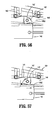
- FIG. 1 is a perspective view of a surgical clip applier
- FIG. 1A is a rear, perspective view of the surgical clip applier of FIG. 1 , shown with a shipping wedge in position;
- FIG. 1B is a cross-sectional view as taken through 1B-1B of FIG. 1A ;
- FIG. 1C is a cross-sectional view as taken through 1C-1C of FIG. 1A ;
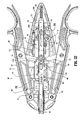
- FIG. 2 is a top, plan view of the surgical clip applier of FIG. 1 ;
- FIG. 3 is a side, elevational view of the surgical clip applier of FIGS. 1 and 2 ;
- FIG. 4 is an exploded perspective view of the surgical clip applier of FIGS. 1-3 ;
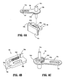
- FIG. 4A is an exploded perspective view of a bell crank gear and accelerator rack assembly of the surgical clip applier of FIGS. 1-4 ;
- FIG. 4B is a perspective view of the accelerator rack of the surgical clip applier of FIGS. 1-4 ;
- FIG. 4C is a perspective view of the bell crank gear of the surgical clip applier of FIGS. 1-4 ;
- FIG. 4D is a top, perspective view of a pivot arm of the surgical clip applier of FIGS. 1-4 ;
- FIG. 4E is a bottom, perspective view of the pivot arm of FIG. 4D ;
- FIG. 4F is a top, perspective view of a clip follower of the surgical clip applier of FIGS. 1-4 ;
- FIG. 4G is a perspective view of an audible/tactile indicator of the surgical clip applier of FIGS. 1-4 ;
- FIG. 4H is a perspective view of a rack member of the surgical clip applier of FIGS. 1-4 ;
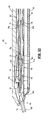
- FIG. 5 is a longitudinal cross-sectional view of the surgical clip applier of FIGS. 1-4 , illustrating the surgical clip applier in an unactuated condition;
- FIG. 6 is an enlarged view of the indicated area of detail of FIG. 5 ;
- FIG. 7 is an enlarged view of the indicated area of detail of FIG. 5 ;
- FIG. 8 is an enlarged view of the indicated area of detail of FIG. 5 ;
- FIG. 9 is a cross-sectional view of the surgical clip applier of FIGS. 1-4 , as taken through 9-9 of FIG. 8 ;
- FIG. 10 is a perspective view of the surgical clip applier of FIGS. 1-4 , illustrated with an upper housing half removed therefrom;
- FIG. 11 is an enlarged view of the surgical clip applier of FIGS. 1-4 , as shown in FIG. 10 ;
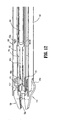
- FIG. 12 is a top, perspective view of a distal end of a channel assembly of the surgical clip applier of FIGS. 1-4 , with a cover removed therefrom;
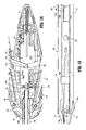
- FIG. 13 is a top, perspective view of the surgical clip applier of FIGS. 1-4 , illustrated with the upper housing half and a pusher bar removed therefrom;
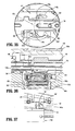
- FIG. 14 is a top, perspective view of a distal end of the channel assembly of FIG. 12 , with the cover and the pusher bar removed therefrom;
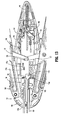
- FIG. 15 is a top, perspective view of a distal end of the channel assembly of FIG. 12 , with the cover, the pusher bar and a clip carrier removed therefrom;
- FIG. 16 is a top, perspective view of a distal end of the channel assembly of FIG. 12 , with the cover, the pusher bar, the clip carrier, the surgical clips and the clip follower , removed therefrom;
- FIG. 17 is an enlarged view of the indicated area of detail of FIG. 16 ;
- FIG. 18 is a top, perspective view of the surgical clip applier of FIGS. 1-4 , illustrated with the upper housing half, the pusher bar and a wedge plate removed therefrom;
- FIG. 19 is a top, perspective view of a distal end of the channel assembly of FIG. 12 , with the cover, the pusher bar, the clip carrier, the surgical clips, the clip follower and the wedge plate removed therefrom;
- FIG. 20 is a top, perspective view of the surgical clip applier of FIGS. 1-4 , illustrated with the upper housing half, the pusher bar, the wedge plate and a drive channel removed therefrom;
- FIG. 21 is a bottom, perspective view of the surgical clip applier of FIGS. 1-4 , illustrated with a lower housing half, the drive channel and the wedge plate removed therefrom;
- FIG. 22 is a top, plan view of the surgical clip applier of FIGS. 1-4 , with the upper housing half removed therefrom and shown in an un-actuated condition;
- FIG. 23 is an enlarged view of the indicated area of detail of FIG. 22 ;
- FIG. 24 is an enlarged view of the indicated area of detail of FIG. 22 ;
- FIG. 25 is a top, plan view of the surgical clip applier of FIGS. 1-4 , with the upper housing half removed therefrom and shown during an initial actuation thereof;
- FIG. 26 is an enlarged view of the indicated area of detail of FIG. 25 ;
- FIG. 27 is an enlarged view of the indicated area of detail of FIG. 27 ;
- FIG. 28 is an enlarged, longitudinal cross-sectional view of the distal end of the channel assembly during the initial actuation of the surgical clip applier;
- FIG. 29 is a cross-sectional view as taken through 29-29 of FIG. 27 ;
- FIG. 30 is an enlarged, longitudinal cross-sectional view of the distal end of the channel assembly during a further initial actuation of the surgical clip applier;
- FIG. 31 is an enlarged view of illustrating the operation of a ratchet assembly and accelerator rack of the surgical clip applier of FIGS. 1-4 ;
- FIGS. 32 and 33 are enlarged view illustrating the operation of an audible/tactile indicator during the respective initial and further actuation of the surgical clip applier of FIGS. 1-4 ;
- FIG. 34 is a top, plan view of the surgical clip applier of FIGS. 1-4 , with the upper housing half removed therefrom and shown during a final actuation of the surgical clip applier;
- FIG. 35 is an enlarged view of the indicated area of detail of FIG. 34 ;
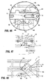
- FIG. 36 is an enlarged, cross-sectional view illustrating an actuation of a counter mechanism of the surgical clip applier of FIGS. 1-4 ;
- FIG. 37 is an enlarged view of a ratchet mechanism shown during the final actuation of the surgical clip applier of FIGS. 1-4 ;
- FIG. 38 is an enlarged, cross-sectional view of the channel assembly illustrating the clip follower during the final actuation of the surgical clip applier of FIGS. 1-4 ;
- FIGS. 39 and 40 are enlarged perspective view, illustrating the distal end of the channel assembly during the final actuation of the surgical clip applier of FIGS. 1-4 ;
- FIG. 41 is a top, plan view of the surgical clip applier of FIGS. 1-4 , with the upper housing half removed therefrom and shown at a final condition after an actuation of the surgical clip applier;
- FIG. 42 is an enlarged view of the indicated area of detail of FIG. 41 ;
- FIG. 43 is an enlarged view illustrating the position of the audible/tactile indicator following an actuation of the surgical clip applier of FIGS. 1-4 ;
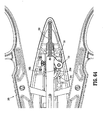
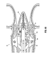
- FIG. 44 is a top, plan view of the jaw assembly illustrating the position of the jaw assembly following an actuation of the surgical clip applier of FIGS. 1-4 ;
- FIG. 45 is a perspective view of a body vessel including a clip of the surgical clip applier, shown applied thereto;
- FIG. 46 is an enlarged view of the indicated areas of detail of FIGS. 34 and 41 , illustrating the operation of the pivot arm during an opening or release of the surgical clip applier following a complete actuation thereof;
- FIG. 47 is an enlarged view of the ratchet mechanism shown during the opening or release of the surgical clip applier of FIGS. 1-4 ;
- FIG. 48 is an enlarged view illustrating the operation of the audible/tactile indicator during the opening or release of the surgical clip applier of FIGS. 1-4 ;
- FIGS. 49 and 50 are longitudinal, cross-sectional views of the channel assembly illustrating the movement of the clip follower during the opening or release of the surgical clip applier of FIGS. 1-4 ;
- FIGS. 51 and 52 are longitudinal, cross-sectional views of the distal end of the channel assembly illustrating the movement of the pusher bar and wedge plate during the opening or release of the surgical clip applier of FIGS. 1-4 ;
- FIG. 53 is a longitudinal, cross-sectional view of the distal end of the channel assembly illustrating the surgical clip applier of FIGS. 1-4 in a locked-out condition following firing of the last surgical clip therefrom;
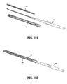
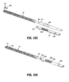
- FIG. 54 is a perspective view of a drive channel including an integral ratchet rack
- FIGS. 55-57 are enlarged schematic illustrations of the operation of a ratchet mechanism of the surgical clip applier including the drive channel of FIG. 54 ;
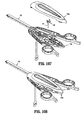
- FIG. 58 is an exploded perspective view of a surgical clip applier
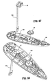
- FIG. 59 is a perspective view of an audible/tactile indicator of the surgical clip applier of FIG. 58 ;
- FIG. 60 is a perspective view of an accelerator rack of the surgical clip applier of FIG. 58 ;
- FIG. 61 is a perspective view of a pinot arm of the surgical clip applier of FIG. 58 ;
- FIG. 62 is a perspective view of a first arm link for the surgical clip applier of FIG. 58 ;
- FIG. 63 is a perspective view of a second arm link for the surgical clip applier of FIG. 58 ;
- FIGS. 64-66 are perspective views of the sequential operation of the audible/tactile indicator and accelerator rack of the surgical clip applier of FIG. 58 , during a complete squeezing of the handles thereof;
- FIGS. 67-69 are perspective views of the sequential operation of the pivot arm and the arm link of the surgical clip applier of FIG. 58 , during a complete squeezing of the handles thereof;
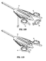
- FIG. 70 is an exploded perspective view of a surgical clip applier
- FIG. 71 is an enlarged perspective view of a gear member of the surgical clip applier of FIG. 70 ;
- FIG. 72 is an enlarged perspective view of a drive channel gear rack of the surgical clip applier of FIG. 70 ;
- FIG. 73 is an enlarged perspective view of a pusher gear rack of the surgical clip applier of FIG. 70 ;
- FIG. 74 is an enlarged perspective view of a proximal end of a pusher bar of the surgical clip applier of FIG. 70 ;
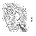
- FIG. 75 is a perspective view of a handle assembly of the surgical clip applier of FIG. 70 , illustrated with a housing half-section removed therefrom and shown in an initial un-squeezed condition;
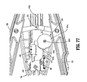
- FIG. 76 is a perspective view of the handle assembly of FIG. 75 shown with the pusher bar also removed therefrom;
- FIG. 77 is a plan view of the handle assembly of FIG. 76 ;
- FIG. 78 is a perspective view of the handle assembly as illustrated in FIG. 75 , shown during an initial squeezing of the triggers;
- FIG. 79 is a plan view of the handle assembly of FIG. 78 ;
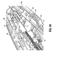
- FIG. 80 is a perspective view of the handle assembly of the surgical clip applier of FIG. 70 , illustrated with a housing half-section removed therefrom and shown during a further squeezing of the triggers;
- FIG. 81 is a perspective view of the handle assembly of FIG. 80 shown with the pusher bar also removed therefrom;
- FIG. 82 is a plan view of the handle assembly of FIG. 81 ;
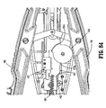
- FIG. 83 is a perspective view of the handle assembly of the surgical clip applier of FIG. 70 , illustrated with the housing half-section removed therefrom and shown during still a further squeezing of the triggers;
- FIG. 84 is a plan view of the handle assembly of FIG. 83 ;
- FIG. 85 is a perspective view of the handle assembly of the surgical clip applier of FIG. 70 , illustrated with the housing half-section removed therefrom and shown during still a final squeezing of the triggers;
- FIG. 86 is a plan view of the handle assembly of FIG. 85 ;
- FIGS. 87-110 illustrate a method of assembling the surgical clip applier of FIGS. 1-57 .
- proximal refers to the end of the apparatus which is closer to the user and the term “distal” refers to the end of the apparatus which is further away from the user.
- Surgical clip applier 100 generally includes a handle assembly 102 including a housing 104 having an upper housing half 104a and lower housing half 104b. Handle assembly 102 further includes a pair of handles 106 pivotably secured to housing 104 and extending outwardly therefrom. A channel assembly 108 is fixedly secured to housing 104 and extends outwardly therefrom, terminating in a jaw assembly 110.
- housing halves 104a and 104b of clip applier 100 fit together by snap fit engagement with one another.
- Housing 104 defines a window 104c formed in lower housing half 104b for supporting and displaying a counter mechanism, as will be discussed in greater detail below.
- Housing 104 is formed of a suitable plastic material.
- handles 106 are secured to housing 104 by handle pivot posts 104d extending from lower housing half 104b and into respective apertures 106a formed in handles 106.
- Handle assembly 102 includes a link member 122 pivotally connected to each handle 106 at a pivot point 106b formed in a respective handle 106.
- a distal end 122a of each link member 122 is pivotally connected to a pivot point 140a formed in a drive channel 140 via a drive pin 124.
- Each end of drive pin 124 is slidably received in an elongate channel 104e formed in a respective upper and lower housing half 104a, 104b.
- Channel assembly 108 includes a channel or cartridge cover 130 and an outer or lower channel 132 each having a proximal end retained in housing assembly 102, between upper and lower housing halves 104a, 104b.
- Cartridge cover 130 includes at least one retention element 130a configured and adapted to selectively engage, in a snap-fit engagement, a complementary or corresponding retention element 132a provided on outer channel 132.
- clip applier 100 includes a clip pusher bar 160 slidably disposed beneath cartridge cover 130.
- Pusher bar 160 includes a distal end 160a defining a pusher 160c configured and adapted to selectively engage/move a distal-most clip "C1" stored in surgical clip applier 100.
- Pusher bar 160 further includes a proximal end 160b defining a proximal window 160d therein for slidably receiving drive pin 124 therein.
- Pusher bar 160 further defines a distal window 160e therein for operative engagement with a stabilizer 162, as will be discussed in greater detail below.
- Pusher bar 160 also includes a fin 160f projecting from a side edge thereof and located in relative close proximity to proximal window 160d.
- Clip applier 100 further includes a stabilizer 162 configured to overlie and engage pusher bar 160.
- Stabilizer 162 includes a distal tab 162a configured to engage distal window 160e of pusher bar 160, an elongate window 162b defined therein at a location to substantially overlie and be in registration with proximal window 160d formed in pusher bar 160.
- Stabilizer 162 further includes a nub 162c extending from a bottom surface thereof, at a location proximal of elongate window 162b, which is configured and dimensioned for receipt in a proximal-most aperture 160g formed in pusher bar 160. As seen in FIGS.
- stabilizer 162 further includes a pair of tabs 162e extending from a top surface thereof, at a proximal and a distal location, which are configured and dimensioned for receipt in respective channels formed in upper housing half 104a.
- clip applier 100 further includes a motion multiplier system having a bell crank gear 154 pivotally supported in housing 104 and an accelerator housing 156 slidably supported in housing 104.
- Bell crank gear 154 includes a pivot pin 154a configured for pivotable connection to housing 104, a disk-like body 154b supported on pivot pin 154a, an arm 154c extending radially from disk-like body 154b, and a spur gear 154d supported on pivot pin 154a or integrally formed therewith and located adjacent disk-like body 154b.
- Bell crank gear 154 defines a detent or notch 154e (see FIG.
- Spur gear 154d of bell crank gear 154 defines a plurality of gear teeth 154g formed in a side edge thereof and may be a sector gear as best shown in FIG. 4C .
- Bell crank gear 154 is a common part for each of the small, medium and large scaled clip appliers 100. Notch 154e formed in side edge of disk-like body 154b of bell crank gear 154 is provided for the assembly of the large scaled clip applier. The larger scaled clip applier requires a greater pusher stroke and therefore a greater degree of rotation of bell crank gear 154. Due to the greater rotation of bell crank gear 154, disk-like body 154b will contact a tab 156e (see FIGS. 4A and 4B ) extending from an accelerator rack 156. During assembly, bell crank gear 154 is rotated until notch 154e contacts tab 156e of accelerator rack 156.
- accelerator rack 156 of motion multiplier system includes a base wall 156a defining an elongate, longitudinally extending slot 156b formed therein, for slidable receipt of pivot pin 154a of bell crank gear 154.
- Accelerator rack 156 includes a side wall 156c projecting in opposite directions from a side edge of base wall 156a, and a gear rack 156d formed in side wall 156c and in registration or alignment with slot 156b of base wall 156a.
- Gear rack 156d is configured for engagement with gear teeth 154g of spur gear 154d of bell crank gear 154.
- Clip applier 100 further includes a biasing member 158 interconnecting accelerator rack 156 and drive channel 140.
- slot 154f of arm 154c of bell crank gear 154 is configured and dimensioned to slidably and rotatably receive a nub 162d of stabilizer 162 therein.
- biasing member 158 which interconnects drive channel 140 and accelerator rack 156, subsequently moves accelerator rack 156 distally.
- accelerator rack 156 causes bell crank gear 154 to rotate and push stabilizer 162 and, in turn, pusher bar 160 distally.
- Clip applier 100 further includes a clip carrier 170 disposed within channel assembly 108 and beneath pusher bar 160.
- Clip carrier 170 is generally a box-like structure having an upper wall 170a, a pair of side walls 170b and a lower wall 170c defining a channel 170d therethrough.
- Clip carrier 170 includes a plurality of spaced apart windows 172 formed in upper wall 170a and extending longitudinally along a length thereof.
- Clip carrier 170 includes an elongate window 170e (see FIG. 9 ) formed in lower wall 170c and extending longitudinally along a length thereof.
- a stack of surgical clips "C” is loaded and/or retained within channel 170d of clip carrier 170 in a manner so as to slide therewithin and/or therealong.
- Channel 170d is configured and dimensioned to slidably retain a stack or plurality of surgical clips "C” in tip-to-tail fashion therewithin.
- a distal end of clip carrier 170 includes a pair of spaced apart, resilient tangs 171. Tangs 171 are configured and adapted to selectively engage a backspan of a distal-most surgical clip "C1" of the stack of surgical clips “C” retained within carrier 170.
- clip applier 100 further includes a clip follower 174 slidably disposed within channel 170d of clip carrier 170.
- clip follower 174 is positioned behind the stack of surgical clips "C” and is provided to urge the stack of clips "C” forward during an actuation of clip applier 100.
- clip follower 174 is actuated by the reciprocating forward and backward motion of wedge plate 180.
- clip follower 174 includes body portion 174a defining a plane, a distal tab 175 extending substantially upwardly and rearwardly from body portion 174a, and a proximal tab 176 extending substantially downwardly and rearwardly from body portion 174a.
- Distal tab 175 includes a distal portion 175a extending downwardly below the plane defined by body portion 174a and a proximal portion 175b extending upwardly above the plane defined by body portion 174a.
- Proximal portion 175b of distal tab 175 is configured and dimensioned to selectively engage windows 172 formed in upper wall 170a of clip carrier 170. In use, engagement of proximal portion 175b of distal tab 175 of clip follower 174 in a window 172 formed in upper wall 170a of clip carrier 170 prevents clip follower from traveling or moving in a proximal direction.
- Proximal tab 176 is configured and dimensioned to selectively engage windows 180b formed in wedge plate 180. In use, engagement of proximal tab 176 of clip follower 174 in a window 180b formed in wedge plate 180 allows for clip follower 174 to be advanced or moved distally upon a distal movement of wedge plate 180.
- clip applier 100 further includes a wedge plate 180 slidably disposed within handle assembly 102 and channel assembly 108.
- Wedge plate 180 is positioned or disposed below clip carrier 170.
- Wedge plate 180 includes a substantially tapered distal end 180a for selective operative interposition between jaws 120.
- Wedge plate 180 defines a plurality of spaced apart windows or apertures 180b extending longitudinally along a length thereof and formed in a raised section thereof, a distal window or aperture 180c located distal of apertures 180b, and a proximal-most transversely oriented slot 180d located proximal of aperture 180c.
- clip applier 100 includes a distal lockout 178 supported by cartridge cover 130.
- Distal lockout 178 includes a tail or tab 178a extending substantially rearwardly and downwardly and being configured and dimensioned for receipt in distal window or aperture 180c of wedge plate 180.
- clip applier 100 includes a wedge plate motion reversing mechanism, in the form of a pivot arm 179, pivotally supported in lower housing half 104b of housing 104 for transmitting the translation of drive channel 140 to a reverse translation of wedge plate 180.
- Pivot arm 179 includes a pivot boss 179a configured for pivotable connection to housing 104, a first stem or finger 179b provided at one end of pivot arm 179 and extending in a direction opposite to pivot boss 179a, and second stem or finger 179c provided at a second end of pivot arm 179 and extending in a direction opposite to pivot boss 179a.
- First stem or finger 179b is configured and adapted for engagement in proximal-most slot 180d of wedge plate 180.
- Second stem or finger 179c is configured for engagement in a slot 140g formed in drive channel 140 which is connected in a window 140g defined in a drive channel 140.
- Slot 140g includes a longitudinally extending distal portion and a longitudinally extending proximal portion that are axially and transversely offset from one another, and a transverse portion interconnecting the distal and proximal portions.
- second stem or finger 179c is moved in a distal direction, rotating pivot arm 179 and thereby moving first stem or finger 179b in a second direction.
- first stem or finger 179b pulls wedge plate 180 out from between jaws 120 urges against as well as urges or pushes proximally against fin 160f of pusher 160 to move pusher 160 in a proximal direction so that pusher bar 160c thereof is removed from between jaws 120, and vice-versa.
- wedge plate 180 is moved in a distal direction, as seen n FIG. 17 , distal end 180a of wedge plate 180 cams against an inner surface of jaws 120 to thereby maintain jaws 120 spaced apart from one another.
- clip applier 100 includes a drive channel 140 reciprocally supported in and extending between housing 104 of handle assembly 102 and channel assembly 108.
- a proximal end of drive channel 140 is supported between upper and lower housing halves 104a, 104b of housing 104 and a distal end of drive channel 140 is supported between cartridge cover 130 and outer channel 132 of channel assembly 108, at a location below wedge plate 180.
- a distal end of drive channel 140 is a substantially U-shaped channel including a pair of spaced apart side walls 140b extending from a backspan 140c thereof, in a direction away from outer channel 132 and toward cartridge cover 130.
- Drive channel 140 further defines a drive pin recess 140a formed in backspan 140c for pivotally receiving drive pin 124 therethrough.
- Drive channel 140 further defines a rib 140e projecting from backspan 140c at a location distal of drive pin recess 140a.
- Drive channel 140 further defines a reciprocation limiting slot 140f formed in backspan 140c at a location distal of slot 140e.
- clip applier 100 includes a drive channel strap 143 secured to drive channel 140.
- Strap 143 is secured to uprights 140b of drive channel 140 so as to extend transversely thereacross. Strap 143 is secured to drive channel 140 at a location distal of reciprocation limiting slot 140f. Strap 143 is secured to drive channel 140 such that wedge plate 180 extends beneath strap 143 and above jaws 120.
- clip applier 100 further includes an audible/tactile indicator 148 connected to drive channel 140 via drive pin 124.
- Indicator 148 includes a resilient finger 148a and a pair of bosses 148b.
- first resilient finger 148a of indicator 148 interacts with corresponding complementary structure or ledge 149 provided in clip applier 100 to create an audible and/or a tactile feedback to the user.
- Bosses 148b of indicator 148 ride within channel 104e formed in upper housing half 104a and provide support to indicator 148 to prevent indicator 148 from rotating.
- clip applier 100 further includes a biasing member 146, in the form of a tension spring, operatively secured to and between a proximal end of drive channel 140 and housing 104, tending to maintain drive channel 140 in a retracted or proximal-most position.
- Biasing member 146 functions to retract or facilitate retraction of drive channel 140 following formation of a clip "C" positioned between jaws 120.
- a proximal end of drive channel 140 includes a ratchet rack member 141 secured to drive pin 124 and movable with drive channel 140.
- Ratchet rack member 141 is configured and adapted to engage with a ratchet pawl 142 supported in housing 104.
- Rack member 141 and pawl 142 define a ratchet mechanism 144. In use, as drive channel 140 is moved axially, rack member 141 is also moved.
- Rack member 141 defines a series of rack teeth 141a having a length which allows pawl 142 to reverse and advance back over rack member 141 when rack member 141 changes between proximal and distal movement as drive channel 140 reaches a proximal-most or distal-most position.
- Pawl 142 is pivotally connected to lower housing half 104b by a pawl pin 147 at a location wherein pawl 142 is in substantial operative engagement with rack member 141.
- Pawl 142 is engageable with rack member 141 to restrict longitudinal movement of rack member 141 and, in turn, drive channel 140.
- Ratchet mechanism 144 further includes a pawl spring 145 configured and positioned to bias pawl 142 into operative engagement with rack member 141.
- Pawl spring 145 functions to maintain the teeth of pawl 142 in engagement with the teeth 141 a of rack member 141, as well as to maintain pawl 142 in a rotated or canted position.
- clip applier 100 includes a pair of jaws 120 mounted on or at a distal end of channel assembly 108 and actuatable by handles 106 of handle assembly 102.
- Jaws 120 are formed of a suitable biocompatible material such as, for example, stainless steel or titanium.
- Jaws 120 are mounted in a distal end of drive channel 140 via a rivet 122 or the like extending through reciprocation limiting slot 140f of drive channel 140 such that jaws 120 are longitudinally stationary relative to outer channel 132 and drive channel 140. As seen in FIGS. 12 , 14 , 17 and 19 , jaws 120 define a channel 120a therebetween for receipt of a surgical clip "C1" therein.
- clip applier 100 further includes a counter mechanism 190 supported in housing 104 of handle assembly 102.
- Counter mechanism 190 includes a display 192, a processor 194, and an energy source 198 in the form of a battery or the like.
- Display 192 is a liquid crystal display that displays one or more operating parameters of clip applier 100 to the surgeon. The operating parameter displayed may be an amount or number of remaining clips, a number of clips that have been used, a position parameter, a surgical time of usage, or any other parameter of the procedure.
- Counter mechanism 190 includes a tab 192a, made from PVC, disposed between battery or energy source 198 and a contact 194a of processor 194 or between the contacts 194a of processor 194 to prevent the battery or energy source 198 from becoming drained during storage.
- tab 192a extends out of housing 104 of clip applier 100 in order to allow for easy removal of the tab therefrom. Once the tab 192a is removed, battery or energy source 198 comes into electrical contact with the contact 194a of processor 194 or between the contacts 194a of the processor 194.
- Counter mechanism 190 is actuated by nub 140e formed in drive channel 140.
- nub 140e formed in drive channel 140.
- nub 140e engages contact 194a causing contact 194a to complete a circuit and trigger processor 194 to perform a function (e.g., reduce the number appearing on display 192 by a give increment or value).
- clip applier 100 includes a shipping wedge 200 supported on housing 104 and interposed between handles 106.
- Shipping wedge 200 functions to maintain handles 106 spaced apart or un-squeezed during a shipment and/or storage of clip applier 100.
- Shipping wedge 200 is connected to tab 192a of counter mechanism 190, such that in order for an end user to use clip applier 100, the end user must remove shipping wedge 200 thereby also removing tab 192a to activate counter mechanism 190.
- shipping wedge 200 includes a body portion 202 in the form of a collar, defining a passage 204 configured and dimensioned for receipt of a portion of housing 104 therein.
- Shipping wedge 200 includes uprights 206 extending outwardly from opposed sides of body portion 202 and being configured to receive handles 106 therein.
- Shipping wedge 200 further includes tabs 208 extending inwardly from opposed sides of uprights 206. Tabs 208 of shipping wedge 200 are configured and dimensioned to engage with handles 106 when shipping wedge 200 is properly secured to clip applier 100.
- accelerator rack 156 With drive channel 140 and pusher bar 160 located at a proximal-most position, accelerator rack 156 is located at a proximal-most position, and second resilient finger 148b of indicator 148 is disposed proximal of edge 149. Also, prior to an initial squeezing of handles 106 of clip applier 100, with wedge plate 180 located at a distal-most position, distal end 180a thereof is interposed between jaws 120.
- a clip “C” is first loaded into jaws 120 during the initial squeezing of handles 106.
- distal ends 122a of link members 122 are caused to be moved distally relative to housing 104.
- drive pin 124 is caused to be moved distally thereby transmitting distal axial movement to drive channel 140.
- biasing member 158 As drive channel 140 is moved distally, biasing member 158 is moved distally therewith. As biasing member 158 is moved distally, biasing member 158 drags accelerator rack 156 in a distal direction. As accelerator rack 156 is dragged in a distal direction, accelerator rack 156 causes bell crank gear 154 to rotate about pivot pin 154a and transmit distal axial movement to nub 162d of stabilizer 162 which, in turn, transmits distal axial movement to pusher bar 160. As drive channel 140 is moved distally biasing member 146 is stretched or extended.
- indicator 148 is moved distally along with the distal movement of drive channel 140.
- indicator 148 functions to create an audible click and/or a tactile vibration, thereby indicating to the user that handles 106 of surgical clip applier 100 have gone through at least a portion of a stroke.
- first resilient arm 148a of audible/tactile indicator 148 rides over and/or along a ledge 149 formed in at least one of upper and lower housing halves 104a, 104b and is flexed thereby.
- audible/tactile indicator 148 As arm 148a of audible/tactile indicator 148 reaches the proximal end of ledge 149, resilient arm 148a snaps over the proximal end of ledge 149 and comes into contact with a surface 149a of ledge 149, thereby creating a first audible sound and a tactile vibration as resilient arm 148a comes into contact with surface 149a of ledge 149.
- the first indication of audible/tactile indicator 148 indicates to the user that a clip "C" has been appropriately loaded.
- drive channel 140 is moved distally until finger 179c of pivot arm 179 is engaged by the transverse portion of slot 140g of drive channel 140 (i.e., the dwell). Once the transverse portion of slot 140g is in abutment with finger 179c of pivot arm 179 (i.e., after the dwell has been exhausted), further distal movement of drive channel 140 causes finger 179c to move and rotate pivot arm 179.
- Rotation of pivot arm 179 causes movement of finger 179b thereof which, in turn, causes wedge plate 180 to be pulled in a proximal direction, thereby withdrawing distal end 180a thereof from between jaws 120 and allowing for jaws 120 to eventually be closed or approximated, and pushes on fin 160f of pusher bar 160 to urge pusher bar 160 in a proximal direction such that distal end pusher member 160c thereof is also moved from between jaws 120 thus allowing for jaws 120 to eventually be closed or approximated.
- pivot arm 179 stops rotating as finger 179c of pivot arm 179 rides through the proximal portion of slot 140g of drive channel 140. Finger 179c of pivot arm 179 remains in the proximal portion of slot 140g of drive channel 140 until the stroke of drive channel 140 is completed.
- wedge plate 180 As seen in FIG. 38 , as wedge plate 180 is moved in a proximal direction, wedge plate 180 is moved proximally relative to clip follower 174 thereby moving windows 180b thereof proximally relative to proximal tab 176 of clip follower 174.
- pusher bar 160 is moved distally with drive channel 140, as described above, until accelerator rack 156 abuts against a rib in lower body 104b of housing 104, at which time distal advancement of accelerator rack 156 is stopped.
- accelerator rack 156 prevented from further distal advancement, as seen in FIG. 32 , as drive channel 140 is further advanced distally, drive channel 140 pulls or flexes resilient finger 148a of indicator 148 over a proximal end of ledge 149.
- a first indication i.e., audible and/or tactile
- bell crank 154 is prevented from rotating and thus pusher bar 160 is prevented from further distal advancement.
- distal ends 122a of link members 122 are caused to be moved further distally relative to housing 104.
- drive pin 124 is caused to be moved further distally thereby transmitting distal axial movement to drive channel 140.
- drive channel strap 143 functions to cap drive channel 140 so as to maintain jaws 120 within drive channel 140 during the approximation of jaws 120 and to maintain wedge plate 180 within drive channel 140 during operation of clip applier 100.
- surgical clip "C1" may be formed or crimped onto a vessel “V” or any other biological tissue.
- Drive channel 140 is permitted to move distally relative to pusher bar 160 due to the translation of bosses 148b of indicator 148 through slot 160d of pusher bar 160.
- drive channel 140 is fully advanced distally, as seen in FIG. 37 , rack member 141 of ratchet mechanism 144 is moved distally to a location beyond pawl 142 such that the teeth 141 a of rack member 141 are moved distally of the tooth of pawl 142 thereby disengaging rack member 141 and pawl 142 from one another. In this manner, drive channel 140 is permitted or free to return to a home or proximal-most position.
- resilient arm 148a of audible/tactile indicator 148 snaps over the distal end of ledge 149 and comes into contact with a surface 149a of ledge 149, thereby creating an audible sound and/or a tactile vibration. Such audible sound and/or tactile vibration coincide with the loading of surgical clip "C".
- clip applier 100 is illustrated following a complete stroke or squeezing of handles 106 and during an opening of handles 106.
- drive channel 140 is at a distal position
- pusher bar 160 is at a distal position
- wedge plate 180 is at a proximal position
- accelerator 156 is spaced a distance from drive channel 140
- each biasing member 146 and 158 are stretched
- pawl 142 is located proximal of rack 140d.
- distal ends 122a of link members 122 are caused to be moved proximally relative to housing 104.
- drive pin 124 is caused to be moved proximally thereby transmitting proximal axial movement to drive channel 140 and, in turn, pusher bar 160.
- the proximal movement of drive channel 140 is facilitated by the constriction of biasing members 146.
- the release of handles 106 results in biasing member 146 withdrawing drive channel 140 in a proximal direction.
- proximal tab 176 of clip follower 174 engages in a window 180b of wedge plate 180 and is thus urged distally a given distance.
- stack of clips "C” is also urged distally.
- clip channel 170 abuts, engages, urges or otherwise cams against proximal portion 175b of distal tab 175 until web 180f of wedge plate 180 rests substantially beneath distal portion 175a of distal tab 175. In so doing, proximal portion 175b of distal tab 175 is moved to extend into an incrementally more distal window 172 of clip channel 170.
- arm 148a of audible/tactile indicator 148 snaps back over ledge 149 and re-sets itself for the next firing stroke or squeeze of handles 106.
- drive channel 140 engages against accelerator rack 156 causing accelerator rack 156 to move in a proximal direction. Movement of accelerator rack 156 in a proximal direction results in rotation of bell crank gear 154 about pivot pin 152a to thereby move pusher bar 160 in a proximal direction. Additionally, as drive channel 140 is moved in a proximal direction, nub 140e thereof disengages contact 194a of processor 194.
- FIG. 53 a distal end of clip applier 100 is illustrated following a complete stroke or squeezing of handles 106 and after a final clip has been expelled therefrom.
- proximal tab 176 of clip follower is disposed within a distal-most aperture or window of apertures 180b of wedge plate 180.
- clip follower 174 is also moved distally. Accordingly, as clip follower 174 is moved distally, distal tab 175 thereof is moved distal of a distal-most window of windows 172 of clip carrier 170. In this manner, proximal portion 175b of distal tab 175 engages against an inner surface of a top wall of clip carrier 170 and is cammed or urged downwardly.
- distal portion 175a of distal tab 175 engages against an upper surface of tab 178a of lockout 178 and cams or urges tab 178a of lockout 178 downwardly, across a path of strap 143, supported on drive channel 140, and into distal window 180c of wedge plate 180.
- strap 143 will abut against tab 178a of lockout 178 and prevent or block strap 143 and, in turn, drive channel 140 from moving distally.
- pawl 142 is located in a dwell, distal of rack 140d, and handles 106 are arranged in a fully opened position and are thus not capable of being opened any further. In this configuration, clip applier is locked out and can no longer be used.
- each clip applier 100 will have to be scaled accordingly.
- the majority of the components of the various sized clip appliers will be substantially identical to one another.
- Components size relating to the width of the clips, such as the jaws 120 and the wedge plate 180, or components size relating to the length of the clip, such as the pusher bar 160, the bell crank gear 154 and the pivot arm 179, are adjusted accordingly.
- each clip applier, of varying size will be assembled in substantially the same manner and the inner mechanism thereof will operate in substantially the same manner.
- clip applier 100 may be provided in a relatively small, medium and large scale, wherein each of the sizes of clip appliers stores and fires a relatively small, medium or large surgical clip. Based on the relative dimensions of the surgical clips, the corresponding clip appliers, and their corresponding components, must be scaled appropriately.
- each of the various sized clip appliers comprise the same component and may be assembled in the same sequence as one another. In this manner, a technician assembling the clip appliers will only have to learn the sequence and/or steps required for the assembly of one of the sizes of clip appliers and, in turn, be able to assemble the other sizes of clip appliers equally, without having to learn a new sequence or step of assembly.
- the assembly method and/or steps for a relatively small, medium or large clip applier are substantially identical to one another.
- At least the following components or parts vary in shape based on the relative size or scale of the clip applier, namely, the length of the arms of pivot arm 179, the length of the slot in which accelerator rack 156 translates; and the degree of rotation of bell crank gear 154.
- a relatively small scaled clip applier that a given rotation of approximately 45°, for a relatively small scaled bell crank gear 154, will result in approximately a 0.345 inch axial displacement of a relatively small scaled pusher bar 160 in order to load a relatively small sized clip into jaws 120.
- a relatively medium scaled clip applier that a given rotation of approximately 70°, for a relatively medium scaled bell crank gear 154, will result in approximately a 0.485 inch axial displacement of a relatively medium scaled pusher bar 160 in order to load a relatively medium sized clip into jaws 120.
- a proximal end of drive channel 140 may include or define a ratchet rack 140d integral therewith that is configured and adapted for engagement with ratchet pawl 142.
- ratchet mechanism 244 is substantially identical to ratchet mechanism 144 and thus will not be discussed in great detail herein.
- clip applier 100 may be provided with a strap 196 configured to secure energy source 198 to housing 104.
- resilient arm 148a of audible/tactile indicator 148 may strike or contact a surface formed in housing 104 thereby amplifying the further or second audible sound and/or tactile vibration.
- Surgical clip applier 300 is substantially identical to surgical clip applier 100 and thus will only be discussed in detail herein to the extent necessary to identify differences in construction and operation thereof.
- clip applier 300 includes motion multiplier system having a bell crank gear 154, and an accelerator rack 356 slidably supported in housing 104.
- Accelerator rack 356 includes a base wall 356a defining an elongate, longitudinally extending slot 356b formed therein, for slidable receipt of pivot pin 154a of bell crank gear 154.
- Accelerator rack 356 includes a side wall 356c projecting in opposite directions from a side edge of base wall 356a, and a gear rack 356d formed in side wall 356c and in registration or alignment with slot 356b of base wall 356a.
- Gear rack 356d is configured for engagement with gear teeth 154g of spur gear 154d of bell crank gear 154.
- Accelerator rack 356 further includes a camming member 356e projecting from a distal edge of base wall 356a, and a nub 356f projecting from distal edge of side wall 356c.
- the length of slot 356b of base wall 356a of accelerator rack 356 will vary depending on the size of clip applier 300. For relatively smaller clip appliers (e.g., clip appliers which apply relatively smaller clips), the length of slot 356b of accelerator rack 356 will be relatively shorter, and for relatively larger clip appliers (e.g., clip appliers which apply relatively larger clips), the length of slot 356b of accelerator rack 356 will be relatively longer.
- gear rack 356d of accelerator rack 356 engages with gear teeth 154g of spur gear 154d of bell crank gear 154 to cause bell crank gear 154 to rotate or pivot about pivot pin 154a.
- clip applier 300 includes a motion reversing mechanism having a wedge plate pivot arm 379 pivotally supported in lower housing half 104b of housing 104 for transmitting translation of wedge plate 180 to translation of drive channel 140.
- Pivot arm 379 includes a pivot boss 379a configured for pivotable connection to housing 104, a first stem or finger 379b provided at one end of pivot arm 379 and extending in a direction opposite to pivot boss 379a, and second stem or finger 379c provided at a second end of pivot arm 379 and extending in a same direction as pivot boss 379a.
- First stem or finger 379b is configured and adapted for engagement in proximal-most slot 180d of wedge plate 180.
- Second stem or finger 379c is configured for engagement in a slot 358b formed in arm link 358 ( FIG. 62 ) which is connected in a window 140h defined in a drive channel 140.
- arm link 358 urges second stem or finger 379c of pivot arm 379 to move in a first or distal direction thereby moving first stem or finger 379b in a second or proximal direction and causing wedge plate 180 to move in the second direction, and vice-versa.
- wedge plate 180 cams against an inner surface of jaws 120 to thereby maintain jaws 120 spaced apart from one another.
- Clip applier 300 further includes a biasing member 384, in the form of a tension spring, operatively secured to and between a proximal end of wedge plate 180 and housing 104, tending to maintain wedge plate 180 in an advanced or distal-most position.
- Biasing member 384 functions to advance or facilitate advancement of wedge plate 180 following formation of a clip "C" positioned between jaws 120.
- clip applier 300 further includes an audible/tactile indicator 348 supported on drive channel 140.
- Indicator 348 includes a first resilient finger 348a and second resilient finger 348b.
- first resilient finger 348a of indicator 348 interacts with corresponding complementary structure provided in clip applier 300 to create an audible and/or a tactile feedback to the user and second resilient finger 348b of indicator 348 interacts with camming member 356e of accelerator rack 356 to adjust the stroke of clip applier 300 for varying sizes of clip applier 300.
- clip applier 300 further includes an arm link 358 slidably disposed in housing 104 and operatively connected to drive channel 140 for translation therewith.
- Arm link 358 includes a body portion 358a defining a slot 358b therein, a guide wall 358c projecting from an upper surface of body portion 358a, and a stem 358d extending in an upward direction from a proximal edge of body portion 358a.
- Slot 358b of arm link 358 is configured to slidably receive second stem or finger 379c of pivot arm 379.
- Guide wall 358c of arm link 358 is dimensioned to ride against a surface of drive channel 140.
- Stem 358d of arm link 358 is dimensioned for slidable receipt in window 140h formed in drive channel 140.
- Window 140h of drive channel 140 is dimensioned to define a period of dwell between when drive channel 140 is moved distally and when arm link 358 actuates pivot arm 379.
- drive pin 124 is at a proximal-most position
- pusher bar 160, stabilizer 162, and drive channel 140 are also at a proximal-most position.
- accelerator rack 356 is located at a proximal-most position
- second resilient finger 348b of indicator 348 is disposed proximal of camming member 356e of accelerator rack 356.
- wedge plate 180 is located at a distal-most position such that distal end 180a of wedge plate 180 is interposed between jaws 120.
- indicator 348 is moved distally therewith.
- second resilient finger 348b thereof drags accelerator rack 356 in a distal direction.
- accelerator rack 356 causes bell crank gear 154 to rotate about pivot pin 154a and transmit distal axial movement to nub 162c of stabilizer 162 which, in turn, transmits distal axial movement to pusher bar 160.
- drive channel 140 is moved distally biasing member 146 is stretched or extended.
- drive channel 140 is moved distally until stem 358d of arm link 358 is engaged by an end wall of window 140h of drive channel 140 (i.e., the dwell). Once the end wall of window 140h is in abutment with stem 358d of arm link 358 (i.e., after the dwell has been exhausted), further distal movement of drive channel 140, as seen in FIG. 69 , results in distal movement of arm link 358.
- pivot arm 379 As arm link 358 is moved distally, the transverse portion of slot 358b of arm link 358 will cause pivot arm 379 to rotate which, in turn, causes wedge plate 380 to move in a proximal direction, thereby withdrawing distal end 180a thereof from between jaws 120 and allowing for jaws 120 to eventually be closed or approximated.
- pivot arm 379 stops rotating as finger 379c of pivot arm 379 rides through longitudinal portion of L-shaped slot 358b of arm link 358. Finger 379c of pivot arm 379 remains in longitudinal portion of L-shaped slot 358b of arm link 358 until the stroke of drive channel 140 is completed.
- pusher bar 160 is moved distally with drive channel 140, as described above, until nub 356f of accelerator rack 356 abuts against a ledge formed in housing 104, at which time distal advancement of accelerator rack 356 is stopped.
- accelerator rack 356 prevented from further distal advancement, as seen in FIG. 66 , as drive channel 140 is further advanced distally, drive channel 140 pulls or flexes second resilient finger 348b of indicator 348 from behind camming member 356e of accelerator rack 356 allowing pusher bar 160 to move in a proximal direction to a home position.
- Pusher bar 160 is retracted to its home position by a return spring 359 having a first end that is secured to pusher bar 160 and a second end that is secured to the housing.
- drive channel 140 is moved in a proximal direction.
- a front end wall of window 140h of drive channel 140 acts on stem 358d of arm link 358 to drawn arm link 358 in a proximal direction.
- arm link 358 causes pivot arm 379 to rotate which, in turn, causes wedge plate 180 to move in a distal direction.
- wedge plate 180 is moved in a distal direction, distal end 180a of wedge plate 180 is reinserted or reintroduced into jaws 120, thereby spreading jaws 120 apart.
- second resilient finger 348b of indicator 348 engages against camming member 356e of accelerator rack 356 causing accelerator rack 356 to move in a proximal direction. Movement of accelerator rack 356 in a proximal direction results in rotation of bell crank gear 152 about pivot pin 152a to thereby move pusher bar 160 and stabilizer 162 in a proximal direction. As drive channel 140 is further moved in a proximal direction, second resilient finger 348b of indicator 348 cams, flexes or snaps behind camming member 356e for re-engagement with accelerator rack 356.
- Surgical clip applier 400 is substantially identical to surgical clip applier 100 and thus will only be discussed in detail herein to the extent necessary to identify differences in construction and operation thereof.
- clip applier 400 includes motion multiplier system having a gear member 454 rotatably supported in housing 404 of handle assembly 402.
- Gear member 454 includes a body plate 454a defining an axis of rotation, a gear 454b supported on body plate 454a and concentric with the axis of rotation, and a gear segment 454c formed at an outer edge of body plate 454a.
- clip applier 400 further includes a drive channel gear rack 442 supported on or otherwise connected to drive channel 440.
- Drive channel gear rack 442 defines a plurality of gear teeth 442a formed in a side edge thereof.
- Drive channel gear rack 442 is configured and dimensioned such that gear teeth 442a thereof are engageable with gear 454b of gear member 454. In use, as drive channel 440 is translated, drive channel gear rack 442 is translated therewith or vice-versa.
- the motion multiplier system of clip applier 400 also includes a pusher bar gear rack 462 supported on or otherwise connected to pusher bar 460.
- Pusher bar gear rack 462 defines a plurality of teeth 462a formed in a side edge thereof, and a stem 462b extending proximally therefrom.
- Pusher bar rack 462 is configured and dimensioned such that gear teeth 462a thereof are engageable with gear segment 454c of gear member 454. In use, as pusher bar 460 is translated, pusher bar gear rack 462 is translated therewith or vice-versa.
- clip applier 400 includes a pusher bar 460 having a resilient finger 460c projecting from a surface thereof.
- resilient finger 460c of pusher bar 460 is disposed distally of a drive block 440a ( FIGS. 75-77 ) extending from drive channel 440.
- no clips "C" are positioned within jaws 106.
- drive channel 440 As drive channel 440 is moved distally, as seen in FIGS. 78 and 79 , drive channel 440 is moved distally. As such, drive block 440a of drive channel 440 engages resilient finger 460c of pusher bar 460 thereby causing pusher bar 460 to be advanced distally as well. As drive channel 440 and pusher bar 460 are moved distally, pusher bar 460 moves pusher gear rack 462 until teeth 462a of pusher gear rack 462 engages gear segment 454c of gear member 454.
- FIGS. 80-82 as handle 106 are further actuated, thus moving drive channel 440 further distally, pusher bar 460 is moved distally an amount sufficient for pusher gear rack 462 to be moved distal and free of gear segment 454c of gear member 454. Also, at this point in time teeth 442a of drive channel gear rack 442 engage with gear 454b of gear member 454, thus preventing gear member 454 from returning to a home position.
- a clip (not shown) has been fully delivered into the jaws by pusher bar 460. Additionally, at this stage pawl 142 has been engaged by rack 140d of drive channel 440. As such, drive channel 440 may not return to a home position until drive channel 440 has completed its distal stroke.
- drive block 440a of drive channel 440 snaps beyond resilient finger 460c of pusher bar 460 thereby allowing extension spring 464 to withdraw pusher bar 460 to a home position.
- drive channel 440 may continue to move distally to fully actuate clip applier 400 and form the surgical clip disposed within the jaws.
- rack 140d of drive channel 440 has moved distally beyond pawl 142 thus allowing for drive channel 440 to return to the home position.
- Assembly of each of the various sized clip appliers 100-400 is accomplished in substantially the same sequence of steps irrespective of the relative size of the clip applier. In this manner, as stated above, a technician assembling the clip appliers will only have to learn the sequence and/or steps required for the assembly of one of the sizes of clip appliers and, in turn, be able to assemble the other sizes of clip appliers equally, without having to learn a new sequence or step of assembly.
- FIGS. 87-110 an exemplary method of assembling a relatively small, medium and/or large clip applier 100 is illustrated.
- a lower housing half 104b is provided and a battery or energy source 198 is seated within lower housing half 104b.
- a processor 192 including a tab 192b, is seated within window 104c of lower housing half 104b such that tab 192b extends outwardly of lower housing half 104b.
- pawl spring 145 and pawl pin 147 are secured or inserted into lower housing half 104b, and pawl 142 is inserted over pawl pin 147 and moved into engagement with pawl spring 145.
- a correspondingly sized pivot arm 179 (e.g., a pivot arm 179 corresponding in size to a length and/or width of the surgical clips) is pivotally attached or seated into lower housing half 104b via pivot boss 179a.
- rack member 141 is slidably positioned within lower housing half 104b such that teeth 141 a of rack member 141 are operatively associated with the teeth of pawl 142.
- a distal opening 141b of rack member 141 overlies elongate channel 104e defined in lower housing half 104b, and a projection 141c of rack member 141 is slidably positioned within a complementary slot defined by lower housing half 104b.
- Channel assembly 108 is connected to lower housing half 104b.
- Channel assembly 108 includes a lower channel 132, a drive channel 140 slidably disposed within lower channel 132, jaws 120 fixedly connected to lower channel 132, and channel strap 143 secured near a distal end of drive channel 140.
- drive pin recess 140a is aligned with opening 141 b of rack member 141.
- second finger 179c of pivot arm 179 is slidably disposed within window 140g of drive channel 140.
- a correspondingly sized wedge plate 180 (e.g., a wedge plate 180 corresponding in size to a length and/or width of the surgical clips) is slidably positioned over drive channel 140 such that a distal end 180a of wedge plate 180 is interposed between channel strap 143 and jaws 120, and a proximal end of wedge plate 180 is connected to first finger 179b of pivot arm 179.
- biasing member 146 is provided and has a first end connected to drive channel 140 and a second end secured to lower housing half 104b.
- an accelerator rack 156 is slidably positioned within lower housing half 104b, and a correspondingly sized bell crank gear 154 (e.g., a bell crank gear 154 corresponding in size to a length and/or width of the surgical clips) pivotally connected to lower housing half 104b via pivot pin 154a, wherein the pivot pin 154a extends through accelerator rack 156.
- a correspondingly sized bell crank gear 154 e.g., a bell crank gear 154 corresponding in size to a length and/or width of the surgical clips
- spur gear 154d of bell crank gear 154 engages gear rack 156d of accelerator rack 156.
- a biasing member 158 is provided and interconnected between drive channel 140 and accelerator rack 156.
- a pair of handles 106 is connected to lower housing half 104b.
- a distal aperture 106a of each handle 106 is pivotally disposed on a respective pivot post 104d of lower housing half 104b.
- link members 122 are provided which are pivotally connected to a respective handle 106 and extend therefrom such that a distal end 122a thereof overlies pivot point 140a of drive channel 140.
- a stack of clips "C” is inserted into a channel 170d of a clip carrier 170.
- a clip follower 174 is placed within channel 170d of clip carrier 170 at a location proximal of the stack of clips “C.”
- twenty-two clips “C” may be loaded into clip carrier 170.
- a correspondingly sized clip carrier 170 and clip follower 174 is provided or selected.
- a correspondingly sized pusher bar 160 (e.g., a pusher bar 160 corresponding in size to a length and/or width of the surgical clips) is slidably disposed in cartridge cover 130, and the loaded clip carrier 170 is fixedly placed within cartridge cover 130 so as to cover a distal end of pusher bar 160.
- a lockout 178 is secured near a distal end of cartridge cover 130.
- a tab 178a of lockout 178 is oriented to extend in a proximal direction.
- a stabilizer 162 is connected to a proximal end of pusher bar 160.
- a distal tab 162a of stabilizer 162 is inserted into a distal window 160e of pusher bar 160, and an elongate window 162b of stabilizer 162 is aligned with a proximal window 160d of pusher bar 160.
- nub 162d of stabilizer 162 extends through pusher bar 160.
- cartridge cover 130 is connected to outer channel 132 such that the proximal end of pusher bar 160 overlies lower housing half 104b.
- proximal window 160d of pusher bar 160 is positioned over distal end 122a of link members 122 and over pivot point 140a of drive channel 140.
- nub 162d of stabilizer 162 is positioned within slot 154f of arm 154c of bell crank gear 154. (see FIG. 4C ).
- a drive pin 124 is inserted through proximal window 160d of pusher bar 160, through each distal end 122a of link members 122, through pivot point 140a of drive channel 140 (see FIGS. 97 and 98 ), through opening 141 b of rack member 141 (see FIGS. 91 and 92 ), and into elongate channel 104e defined in lower housing half 104b (see FIGS. 91 and 92 ).
- an audible/tactile indicator 148 is connected to drive pin 124 so as to move therewith.
- upper housing half 104a is secured to lower housing half 104b.
- a shipping wedge 200 is introduced between handles 106 and connected to housing 104. Additionally, a distal or free end of tab 192b is connected to shipping wedge 200 such that upon removal of shipping wedge 200 from housing 104 results in removal of tab 192b and activation of the counter mechanism.
Description
- The present application relates to surgical instruments and more particularly, to surgical clip appliers having a plurality of clips for applying the clips to body tissues and vessels during surgical procedures.
- Surgical clip appliers are known in the art and have increased in popularity among surgeons by offering an alternative to conventional suturing of body tissues and vessels. Typical instruments are disclosed in
U.S. Pat. No. 5,030,226 to Green et al. andU.S. Pat. No. 5,431,668 to Burbank III et al. These instruments generally provide a plurality of clips which are stored in the instrument and which are fed sequentially to the jaw mechanism at the distal end of the instrument upon opening and closing of the handles at the proximal end of the instrument. As the handles are closed, the jaws close to deform a clip positioned between the jaw members, and as the jaws are opened to release the deformed clip, a new clip is fed from the series to a position between the jaws. This process is repeated until all the clips in the series of clips have been used. - Surgical clip appliers are typically available in a variety of sizes and/or scales ranging from relatively small, relatively medium to relatively large. Generally, each particular size of surgical clip appliers includes different components. As such, the method of assembling the various sized surgical clip appliers differs from one size to another,
- As a consequence, the technicians must be taught different routines and procedures for assembling the various sized surgical clip appliers. As a result, errors in the assembling of the various sized surgical clip appliers may occur on an elevated level as the technicians' mistake the assembly procedure of one sized surgical clip applier for the assembly procedure of another sized surgical clip applier.
- The need therefore exists for a family of different sized instruments for applying surgical clips which may be assembled in the same manner from one size to another size.
- Also, a need exists for a uniform method, which is not part of the invention, of assembling each of the different sized instruments in order to improve the efficiency of production.
The pre-characterising features of claim 1 are from the Applicant's earlier applicationWO 2008/127968 . - The present application relates to surgical clip appliers having a plurality of clips for applying the clips to body tissues and vessels during surgical procedures.
- The present invention provides a clip applier in accordance with Claim 1.
- The surgical clip applier comprises; (i) a housing; (ii) a drive channel defining a stroke length; (iii) a pusher bar defining a corresponding stroke length; (iv) a wedge plate defining a corresponding stroke length; (v) a motion multiplier system interconnecting the drive channel and the pusher bar comprising a bell crank gear pivotally supported in said housing and an accelerator housing slidably supported in the housing, wherein the motion multiplier transmits a motion of the drive channel to a motion of the pusher bar, wherein the displacement of the drive channel in the first direction actuates the motion multiplier system to actuate the pusher bar in a first direction by an amount substantially equal to the particular length of the stroke thereof for the respective relatively small, medium and large scaled surgical clip applier; and (vi) a motion reversing mechanism interconnecting the drive channel and the wedge plate, wherein the reversing mechanism transmits a motion of the drive channel to a motion of the wedge plate, wherein the displacement of the drive channel in the first direction actuates the motion reversing mechanism to actuate the wedge plate, in a direction opposite the first direction of drive channel, by an amount substantially equal to the particular length of the stroke thereof for the respective relatively small, medium and large scaled surgical clip applier.
- There is described a surgical clip applier including a housing; at least one handle pivotably connected to the housing; a channel assembly extending from the housing; a clip carrier disposed within said channel assembly and defining a channel and a plurality of windows therein; a plurality of clips slidably disposed within said channel of said clip carrier; a wedge plate reciprocally disposed within said channel assembly, said wedge plate being operatively connected to said handles and including a plurality of apertures formed along a length thereof; and a clip follower slidably disposed within said channel of said clip carrier at a location proximal of said plurality of clips, said clip follower being configured and adapted for selective engagement with said windows of said clip carrier and said apertures of said wedge plate. The clip follower is configured and adapted to distally urge said plurality of clips relative to said clip carrier upon reciprocal movement of said wedge plate.
- The clip follower may be configured to engage the wedge plate and move distally upon distal translation of the wedge plate, and may be configured to engage the clip carrier and stop proximal movement thereof upon proximal translation of the wedge plate.
- The clip applier may further include a jaw assembly including a pair of jaws extending from an end of said channel assembly, opposite said housing. The jaw assembly may be adapted to accommodate a clip therein and may be operable to effect formation of a clip in response to movement of said handles.
- The clip applier further includes a clip pusher bar reciprocally positioned within at least one of said housing and said channel assembly. The pusher bar may have a first end operatively connected to said at least one handle and a second end defining a pusher. The pusher bar may be movable towards said jaws as said at least one handle is moved in a first direction by an initial amount in order to move a distal-most clip between said jaws. The pusher bar may be configured and adapted to move towards said housing as said at least one handle is moved an additional amount in said first direction to move said pusher behind a distal-most clip in said plurality of clips.
- The clip applier further include a motion multiplier system configured to distally move the pusher bar by an incremental amount upon an initial actuation of the handles, and configured to proximally move the pusher bar and the wedge plate subsequent to the initial actuation of the handles.
- The clip applier further includes a drive channel translatably slidably disposed within at least one of said housing and said channel assembly. The drive channel may have a first end operatively connected to at least one of said handles and a second end configured and dimensioned to selectively engage said pair of jaws to effectuate closure of said pair of jaws. The drive channel may be moved towards said jaw assembly as said handles are actuated in a first direction to move said second end thereof against said jaws to close said jaws. The drive channel may be moved away from said jaws as said handles are moved in a second direction to move said second end thereof away from said jaws to allow said jaws to open.
- The clip applier further includes a pivot arm operatively connected to said wedge plate and said drive channel. Rotation of said pivot arm, during distal movement of said drive channel, may result in proximal movement of said wedge plate.
- The clip applier further includes a motion multiplier system having a bell crank gear pivotally supported in the housing and pivotally connected to the pusher bar; an accelerator rack slidably supported in the housing and operatively joined to the bell crank gear; and a biasing member interconnecting the drive channel and the accelerator rack. A distal translation of the drive channel causes distal translation of the accelerator rack via the biasing member. Distal translation of the accelerator rack causes a first rotation of the bell crank gear and distal translation of the pusher bar.
- The bell crank gear may include an arm extending radially therefrom and an elongate slot formed in the arm, wherein the elongate slot slidably receives a boss operatively associated with the pusher bar.
- The clip applier further includes a motion reversing mechanism operatively connected to said drive channel and said wedge plate and selectively engageable with said pusher bar. Rotation of said motion reversing mechanism, during said distal translation of said drive channel, results in proximal movement of said wedge plate and said pusher bar.
- The clip applier may further comprise a ratchet mechanism including a rack, having a plurality of ratchet teeth, associated with said drive channel; and a pawl, having at least one tooth, disposed at a location to selectively engage said rack. The pawl may be biased into engagement with said rack. As said drive channel is longitudinally reciprocated, said plurality of teeth may be passed over said pawl. The pawl may prevent inadvertent return of said drive channel before full actuation of said at least one handle.
- The clip applier may further include a lockout disposed in a distal end of said channel assembly. The lockout may be actuated by said clip follower when a last clip is expelled from said clip applier. The lockout may be urged by said clip follower to extend across a path of said drive channel, thereby preventing said drive channel from moving distally.
- The clip applier may further include a counter mechanism supported in at least one of said housing and said channel assembly. The counter mechanism may be configured and adapted to display a change in said clip applier upon each actuation of said handles.
- The drive channel may be configured and dimensioned to at least partially surround said jaws and said wedge plate. The drive channel may include a strap extending across a distal end thereof for maintaining said jaws and said wedge plate within said drive channel.
- A surgical clip applier is described including a housing; at least one handle pivotably connected to opposite sides of the housing; a channel assembly fixed to and extending from the housing; a pair of jaws supported on and extending from a distal end of the channel assembly; a clip carrier disposed within said channel assembly and defining a channel; a plurality of clips slidably disposed within said channel of said clip carrier; a clip follower slidably disposed within said channel of said clip carrier at a location proximal of said plurality of clips; a drive channel translatably disposed within at least one of said housing and said channel assembly, said drive channel having a first end operatively connected to at least one of said handles and a second end configured and dimensioned to selectively engage said pair of jaws to effectuate closure thereof; a pusher bar translatably disposed within at least one of said housing and said channel assembly, said pusher bar being connected to said drive channel via a motion multiplier system, a distal end of said pusher bar being configured to engage a distal-most clip of the plurality of clips; a wedge plate reciprocally disposed within at least one of said housing and said channel assembly, wherein a distal end of said wedge plate is selectively insertable between said pair of jaws; and a motion reversing mechanism including a first end connected to said drive channel, and a second end connected to said wedge plate and engageable by said pusher bar. In use, distal translation of said drive channel causes said pusher bar to translate distally via said motion multiplier system; and distal translation of said drive channel causes said pusher bar and said wedge plate to translate proximally, via said motion reversing mechanism, following a dwell period.
- The wedge plate may define a plurality of apertures formed along a length thereof. The clip carrier may define a plurality of windows formed along a length thereof. The clip follower may be configured and adapted for selective engagement with said windows of said clip carrier and said apertures of said wedge plate. The clip follower may be configured and adapted to distally incrementally urge said plurality of clips relative to said clip carrier upon a distal advancement of said wedge plate.
- The clip applier may further include an indicator configured to create at least one of an audible indication and a tactile indication upon at least one of a loading of a clip into said pair of jaws and a formation of a clip by said pair of jaws.
- The motion multiplier system may include an accelerator rack having a series of teeth and the bell crank gear may include a series of teeth engaged with the teeth of the accelerator rack. Axial translation of the accelerator rack may result in rotation of the bell crank gear and axial translation of the pusher bar.
- The accelerator rack may be connected to the drive channel via a biasing member.
- Further described is a surgical clip applier mechanism operable to deliver at least relatively small, medium and large surgical clips, the surgical clip applier mechanism is provided and includes a drive channel capable of translatable movement; a pair of jaws engageable by a distal end of the drive channel, wherein the pair of jaws are approximated upon distal translation of the drive channel; a wedge plate capable of reciprocal translation relative to the drive channel, wherein a distal end of the wedge plate is selectively positionable between the pair of jaws, the wedge plate defining a plurality of apertures formed along a length thereof; a clip carrier fixedly located with respect to the drive channel, the clip carrier defining a channel and a plurality of windows formed along a length thereof; a plurality of clips slidably disposed within said channel of said clip carrier; a clip follower slidably disposed within said channel of said clip carrier at a location proximal of said plurality of clips; a pusher bar capable of reciprocal translation relative to the drive channel, wherein a distal end of the pusher bar is configured for engagement with a distal-most clip of the plurality of clips; a motion multiplier system including bell crank gear and an accelerator rack, the accelerator rack being coupled to the drive channel via a biasing member, the bell crank gear being coupled to the accelerator rack via complementary gear teeth, and the bell crank gear being coupled to the pusher bar, wherein distal translation of the drive channel causes the accelerator rack to translate distally, causing the bell crank gear to rotate, causing the pusher bar to translate distally; and a pivot arm including a first end connected to the drive channel, and a second end connected to the wedge plate and engageable by the pusher bar. In use, distal translation of the drive channel causes the first end of the pivot arm to translate distally, causing the second end of the pivot arm to translate in a proximal direction, thus causing the wedge plate to translate in a proximal direction; and distal translation of the pusher bar is stopped upon contact of the pusher bar with the second end of the pivot arm.
- The further translation of the second end of the pivot arm in the proximal direction may cause the pusher bar to translate in a proximal direction. Actuation of the pivot arm by the drive channel may occur after a dwell period.
- The present clip applier will be more fully appreciated as the same becomes better understood from the following detailed description when considered in connection with the following drawings, in which:
-
FIG. 1 is a perspective view of a surgical clip applier; -
FIG. 1A is a rear, perspective view of the surgical clip applier ofFIG. 1 , shown with a shipping wedge in position; -
FIG. 1B is a cross-sectional view as taken through 1B-1B ofFIG. 1A ; -
FIG. 1C is a cross-sectional view as taken through 1C-1C ofFIG. 1A ; -
FIG. 2 is a top, plan view of the surgical clip applier ofFIG. 1 ; -
FIG. 3 is a side, elevational view of the surgical clip applier ofFIGS. 1 and2 ; -
FIG. 4 is an exploded perspective view of the surgical clip applier ofFIGS. 1-3 ; -
FIG. 4A is an exploded perspective view of a bell crank gear and accelerator rack assembly of the surgical clip applier ofFIGS. 1-4 ; -
FIG. 4B is a perspective view of the accelerator rack of the surgical clip applier ofFIGS. 1-4 ; -
FIG. 4C is a perspective view of the bell crank gear of the surgical clip applier ofFIGS. 1-4 ; -
FIG. 4D is a top, perspective view of a pivot arm of the surgical clip applier ofFIGS. 1-4 ; -
FIG. 4E is a bottom, perspective view of the pivot arm ofFIG. 4D ; -
FIG. 4F is a top, perspective view of a clip follower of the surgical clip applier ofFIGS. 1-4 ; -
FIG. 4G is a perspective view of an audible/tactile indicator of the surgical clip applier ofFIGS. 1-4 ; -
FIG. 4H is a perspective view of a rack member of the surgical clip applier ofFIGS. 1-4 ; -
FIG. 5 is a longitudinal cross-sectional view of the surgical clip applier ofFIGS. 1-4 , illustrating the surgical clip applier in an unactuated condition; -
FIG. 6 is an enlarged view of the indicated area of detail ofFIG. 5 ; -
FIG. 7 is an enlarged view of the indicated area of detail ofFIG. 5 ; -
FIG. 8 is an enlarged view of the indicated area of detail ofFIG. 5 ; -
FIG. 9 is a cross-sectional view of the surgical clip applier ofFIGS. 1-4 , as taken through 9-9 ofFIG. 8 ; -
FIG. 10 is a perspective view of the surgical clip applier ofFIGS. 1-4 , illustrated with an upper housing half removed therefrom; -
FIG. 11 is an enlarged view of the surgical clip applier ofFIGS. 1-4 , as shown inFIG. 10 ; -
FIG. 12 is a top, perspective view of a distal end of a channel assembly of the surgical clip applier ofFIGS. 1-4 , with a cover removed therefrom; -
FIG. 13 is a top, perspective view of the surgical clip applier ofFIGS. 1-4 , illustrated with the upper housing half and a pusher bar removed therefrom; -
FIG. 14 is a top, perspective view of a distal end of the channel assembly ofFIG. 12 , with the cover and the pusher bar removed therefrom; -
FIG. 15 is a top, perspective view of a distal end of the channel assembly ofFIG. 12 , with the cover, the pusher bar and a clip carrier removed therefrom; -
FIG. 16 is a top, perspective view of a distal end of the channel assembly ofFIG. 12 , with the cover, the pusher bar, the clip carrier, the surgical clips and the clip follower , removed therefrom; -
FIG. 17 is an enlarged view of the indicated area of detail ofFIG. 16 ; -
FIG. 18 is a top, perspective view of the surgical clip applier ofFIGS. 1-4 , illustrated with the upper housing half, the pusher bar and a wedge plate removed therefrom; -
FIG. 19 is a top, perspective view of a distal end of the channel assembly ofFIG. 12 , with the cover, the pusher bar, the clip carrier, the surgical clips, the clip follower and the wedge plate removed therefrom; -
FIG. 20 is a top, perspective view of the surgical clip applier ofFIGS. 1-4 , illustrated with the upper housing half, the pusher bar, the wedge plate and a drive channel removed therefrom; -
FIG. 21 is a bottom, perspective view of the surgical clip applier ofFIGS. 1-4 , illustrated with a lower housing half, the drive channel and the wedge plate removed therefrom; -
FIG. 22 is a top, plan view of the surgical clip applier ofFIGS. 1-4 , with the upper housing half removed therefrom and shown in an un-actuated condition; -
FIG. 23 is an enlarged view of the indicated area of detail ofFIG. 22 ; -
FIG. 24 is an enlarged view of the indicated area of detail ofFIG. 22 ; -
FIG. 25 is a top, plan view of the surgical clip applier ofFIGS. 1-4 , with the upper housing half removed therefrom and shown during an initial actuation thereof; -
FIG. 26 is an enlarged view of the indicated area of detail ofFIG. 25 ; -
FIG. 27 is an enlarged view of the indicated area of detail ofFIG. 27 ; -
FIG. 28 is an enlarged, longitudinal cross-sectional view of the distal end of the channel assembly during the initial actuation of the surgical clip applier; -
FIG. 29 is a cross-sectional view as taken through 29-29 ofFIG. 27 ; -
FIG. 30 is an enlarged, longitudinal cross-sectional view of the distal end of the channel assembly during a further initial actuation of the surgical clip applier; -
FIG. 31 is an enlarged view of illustrating the operation of a ratchet assembly and accelerator rack of the surgical clip applier ofFIGS. 1-4 ; -
FIGS. 32 and 33 are enlarged view illustrating the operation of an audible/tactile indicator during the respective initial and further actuation of the surgical clip applier ofFIGS. 1-4 ; -
FIG. 34 is a top, plan view of the surgical clip applier ofFIGS. 1-4 , with the upper housing half removed therefrom and shown during a final actuation of the surgical clip applier; -
FIG. 35 is an enlarged view of the indicated area of detail ofFIG. 34 ; -
FIG. 36 is an enlarged, cross-sectional view illustrating an actuation of a counter mechanism of the surgical clip applier ofFIGS. 1-4 ; -
FIG. 37 is an enlarged view of a ratchet mechanism shown during the final actuation of the surgical clip applier ofFIGS. 1-4 ; -
FIG. 38 is an enlarged, cross-sectional view of the channel assembly illustrating the clip follower during the final actuation of the surgical clip applier ofFIGS. 1-4 ; -
FIGS. 39 and 40 are enlarged perspective view, illustrating the distal end of the channel assembly during the final actuation of the surgical clip applier ofFIGS. 1-4 ; -
FIG. 41 is a top, plan view of the surgical clip applier ofFIGS. 1-4 , with the upper housing half removed therefrom and shown at a final condition after an actuation of the surgical clip applier; -
FIG. 42 is an enlarged view of the indicated area of detail ofFIG. 41 ; -
FIG. 43 is an enlarged view illustrating the position of the audible/tactile indicator following an actuation of the surgical clip applier ofFIGS. 1-4 ; -
FIG. 44 is a top, plan view of the jaw assembly illustrating the position of the jaw assembly following an actuation of the surgical clip applier ofFIGS. 1-4 ; -
FIG. 45 is a perspective view of a body vessel including a clip of the surgical clip applier, shown applied thereto; -
FIG. 46 is an enlarged view of the indicated areas of detail ofFIGS. 34 and41 , illustrating the operation of the pivot arm during an opening or release of the surgical clip applier following a complete actuation thereof; -
FIG. 47 is an enlarged view of the ratchet mechanism shown during the opening or release of the surgical clip applier ofFIGS. 1-4 ; -
FIG. 48 is an enlarged view illustrating the operation of the audible/tactile indicator during the opening or release of the surgical clip applier ofFIGS. 1-4 ; -
FIGS. 49 and 50 are longitudinal, cross-sectional views of the channel assembly illustrating the movement of the clip follower during the opening or release of the surgical clip applier ofFIGS. 1-4 ; -
FIGS. 51 and 52 are longitudinal, cross-sectional views of the distal end of the channel assembly illustrating the movement of the pusher bar and wedge plate during the opening or release of the surgical clip applier ofFIGS. 1-4 ; -
FIG. 53 is a longitudinal, cross-sectional view of the distal end of the channel assembly illustrating the surgical clip applier ofFIGS. 1-4 in a locked-out condition following firing of the last surgical clip therefrom; -
FIG. 54 is a perspective view of a drive channel including an integral ratchet rack; -
FIGS. 55-57 are enlarged schematic illustrations of the operation of a ratchet mechanism of the surgical clip applier including the drive channel ofFIG. 54 ; -
FIG. 58 is an exploded perspective view of a surgical clip applier; -
FIG. 59 is a perspective view of an audible/tactile indicator of the surgical clip applier ofFIG. 58 ; -
FIG. 60 is a perspective view of an accelerator rack of the surgical clip applier ofFIG. 58 ; -
FIG. 61 is a perspective view of a pinot arm of the surgical clip applier ofFIG. 58 ; -
FIG. 62 is a perspective view of a first arm link for the surgical clip applier ofFIG. 58 ; -
FIG. 63 is a perspective view of a second arm link for the surgical clip applier ofFIG. 58 ; -
FIGS. 64-66 are perspective views of the sequential operation of the audible/tactile indicator and accelerator rack of the surgical clip applier ofFIG. 58 , during a complete squeezing of the handles thereof; -
FIGS. 67-69 are perspective views of the sequential operation of the pivot arm and the arm link of the surgical clip applier ofFIG. 58 , during a complete squeezing of the handles thereof; -
FIG. 70 is an exploded perspective view of a surgical clip applier; -
FIG. 71 is an enlarged perspective view of a gear member of the surgical clip applier ofFIG. 70 ; -
FIG. 72 is an enlarged perspective view of a drive channel gear rack of the surgical clip applier ofFIG. 70 ; -
FIG. 73 is an enlarged perspective view of a pusher gear rack of the surgical clip applier ofFIG. 70 ; -
FIG. 74 is an enlarged perspective view of a proximal end of a pusher bar of the surgical clip applier ofFIG. 70 ; -
FIG. 75 is a perspective view of a handle assembly of the surgical clip applier ofFIG. 70 , illustrated with a housing half-section removed therefrom and shown in an initial un-squeezed condition; -
FIG. 76 is a perspective view of the handle assembly ofFIG. 75 shown with the pusher bar also removed therefrom; -
FIG. 77 is a plan view of the handle assembly ofFIG. 76 ; -
FIG. 78 is a perspective view of the handle assembly as illustrated inFIG. 75 , shown during an initial squeezing of the triggers; -
FIG. 79 is a plan view of the handle assembly ofFIG. 78 ; -
FIG. 80 is a perspective view of the handle assembly of the surgical clip applier ofFIG. 70 , illustrated with a housing half-section removed therefrom and shown during a further squeezing of the triggers; -
FIG. 81 is a perspective view of the handle assembly ofFIG. 80 shown with the pusher bar also removed therefrom; -
FIG. 82 is a plan view of the handle assembly ofFIG. 81 ; -
FIG. 83 is a perspective view of the handle assembly of the surgical clip applier ofFIG. 70 , illustrated with the housing half-section removed therefrom and shown during still a further squeezing of the triggers; -
FIG. 84 is a plan view of the handle assembly ofFIG. 83 ; -
FIG. 85 is a perspective view of the handle assembly of the surgical clip applier ofFIG. 70 , illustrated with the housing half-section removed therefrom and shown during still a final squeezing of the triggers; -
FIG. 86 is a plan view of the handle assembly ofFIG. 85 ; and -
FIGS. 87-110 illustrate a method of assembling the surgical clip applier ofFIGS. 1-57 . - Examples of surgical clip appliers in accordance with the present disclosure will now be described in detail with reference to the drawing figures wherein like reference numerals identify similar or identical structural elements. As shown in the drawings and described throughout the following description, as is traditional when referring to relative positioning on a surgical instrument, the term "proximal" refers to the end of the apparatus which is closer to the user and the term "distal" refers to the end of the apparatus which is further away from the user.
- Referring now to
FIGS. 1-5 , a surgical clip applier in accordance with an example of the present disclosure is generally designated as 100.Surgical clip applier 100 generally includes ahandle assembly 102 including ahousing 104 having anupper housing half 104a andlower housing half 104b. Handle assembly 102 further includes a pair ofhandles 106 pivotably secured tohousing 104 and extending outwardly therefrom. Achannel assembly 108 is fixedly secured tohousing 104 and extends outwardly therefrom, terminating in ajaw assembly 110. - As seen in
FIGS. 1-4 ,housing halves clip applier 100 fit together by snap fit engagement with one another.Housing 104 defines awindow 104c formed inlower housing half 104b for supporting and displaying a counter mechanism, as will be discussed in greater detail below.Housing 104 is formed of a suitable plastic material. - As seen in
FIG. 4 , handles 106 are secured tohousing 104 byhandle pivot posts 104d extending fromlower housing half 104b and intorespective apertures 106a formed inhandles 106.Handle assembly 102 includes alink member 122 pivotally connected to each handle 106 at apivot point 106b formed in arespective handle 106. Adistal end 122a of eachlink member 122 is pivotally connected to apivot point 140a formed in adrive channel 140 via adrive pin 124. Each end ofdrive pin 124 is slidably received in anelongate channel 104e formed in a respective upper andlower housing half handles 106 are squeezed, linkmembers 122push drive channel 140 distally viadrive pin 124. -
Channel assembly 108 includes a channel orcartridge cover 130 and an outer orlower channel 132 each having a proximal end retained inhousing assembly 102, between upper andlower housing halves Cartridge cover 130 includes at least oneretention element 130a configured and adapted to selectively engage, in a snap-fit engagement, a complementary orcorresponding retention element 132a provided onouter channel 132. - As seen in
FIGS. 4 and6-12 ,clip applier 100 includes aclip pusher bar 160 slidably disposed beneathcartridge cover 130.Pusher bar 160 includes adistal end 160a defining apusher 160c configured and adapted to selectively engage/move a distal-most clip "C1" stored insurgical clip applier 100.Pusher bar 160 further includes aproximal end 160b defining aproximal window 160d therein for slidably receivingdrive pin 124 therein.Pusher bar 160 further defines adistal window 160e therein for operative engagement with astabilizer 162, as will be discussed in greater detail below.Pusher bar 160 also includes afin 160f projecting from a side edge thereof and located in relative close proximity toproximal window 160d. -
Clip applier 100 further includes astabilizer 162 configured to overlie and engagepusher bar 160.Stabilizer 162 includes adistal tab 162a configured to engagedistal window 160e ofpusher bar 160, anelongate window 162b defined therein at a location to substantially overlie and be in registration withproximal window 160d formed inpusher bar 160.Stabilizer 162 further includes anub 162c extending from a bottom surface thereof, at a location proximal ofelongate window 162b, which is configured and dimensioned for receipt in aproximal-most aperture 160g formed inpusher bar 160. As seen inFIGS. 4 and6 ,stabilizer 162 further includes a pair oftabs 162e extending from a top surface thereof, at a proximal and a distal location, which are configured and dimensioned for receipt in respective channels formed inupper housing half 104a. - As seen in
FIGS. 4 and4A-4C ,clip applier 100 further includes a motion multiplier system having abell crank gear 154 pivotally supported inhousing 104 and anaccelerator housing 156 slidably supported inhousing 104. Bell crankgear 154 includes apivot pin 154a configured for pivotable connection tohousing 104, a disk-like body 154b supported onpivot pin 154a, anarm 154c extending radially from disk-like body 154b, and aspur gear 154d supported onpivot pin 154a or integrally formed therewith and located adjacent disk-like body 154b. Bell crankgear 154 defines a detent or notch 154e (seeFIG. 24 ) formed in a side edge of disk-like body 154b and a longitudinally orientedslot 154f formed inarm 154c.Spur gear 154d of bell crankgear 154 defines a plurality ofgear teeth 154g formed in a side edge thereof and may be a sector gear as best shown inFIG. 4C . - Bell crank
gear 154 is a common part for each of the small, medium and large scaledclip appliers 100.Notch 154e formed in side edge of disk-like body 154b of bell crankgear 154 is provided for the assembly of the large scaled clip applier. The larger scaled clip applier requires a greater pusher stroke and therefore a greater degree of rotation of bell crankgear 154. Due to the greater rotation of bell crankgear 154, disk-like body 154b will contact atab 156e (seeFIGS. 4A and 4B ) extending from anaccelerator rack 156. During assembly, bell crankgear 154 is rotated untilnotch 154econtacts tab 156e ofaccelerator rack 156. - With continued reference to
FIGS. 4 and4A-4C ,accelerator rack 156 of motion multiplier system includes abase wall 156a defining an elongate, longitudinally extendingslot 156b formed therein, for slidable receipt ofpivot pin 154a of bell crankgear 154.Accelerator rack 156 includes aside wall 156c projecting in opposite directions from a side edge ofbase wall 156a, and agear rack 156d formed inside wall 156c and in registration or alignment withslot 156b ofbase wall 156a.Gear rack 156d is configured for engagement withgear teeth 154g ofspur gear 154d of bell crankgear 154. -
Clip applier 100 further includes a biasingmember 158 interconnectingaccelerator rack 156 and drivechannel 140. - As seen in
FIG. 6 ,slot 154f ofarm 154c of bell crankgear 154 is configured and dimensioned to slidably and rotatably receive anub 162d ofstabilizer 162 therein. In use, asdrive channel 140 is translated distally, biasingmember 158, which interconnectsdrive channel 140 andaccelerator rack 156, subsequently movesaccelerator rack 156 distally. Asaccelerator rack 156 is moved distally, since nub 162d ofstabilizer 162 rides inslot 154f ofarm 154c of bell crankgear 154,accelerator rack 156 causes bell crankgear 154 to rotate and pushstabilizer 162 and, in turn,pusher bar 160 distally. -
Clip applier 100 further includes aclip carrier 170 disposed withinchannel assembly 108 and beneathpusher bar 160.Clip carrier 170 is generally a box-like structure having anupper wall 170a, a pair ofside walls 170b and alower wall 170c defining achannel 170d therethrough.Clip carrier 170 includes a plurality of spaced apartwindows 172 formed inupper wall 170a and extending longitudinally along a length thereof.Clip carrier 170 includes anelongate window 170e (seeFIG. 9 ) formed inlower wall 170c and extending longitudinally along a length thereof. - As seen in
FIGS. 4 ,9 and14 , a stack of surgical clips "C" is loaded and/or retained withinchannel 170d ofclip carrier 170 in a manner so as to slide therewithin and/or therealong.Channel 170d is configured and dimensioned to slidably retain a stack or plurality of surgical clips "C" in tip-to-tail fashion therewithin. - As seen in
FIGS. 12 and14 , a distal end ofclip carrier 170 includes a pair of spaced apart,resilient tangs 171.Tangs 171 are configured and adapted to selectively engage a backspan of a distal-most surgical clip "C1" of the stack of surgical clips "C" retained withincarrier 170. - As seen in
FIGS. 4 ,4F ,7 and15 ,clip applier 100 further includes aclip follower 174 slidably disposed withinchannel 170d ofclip carrier 170. As will be discussed in greater detail below,clip follower 174 is positioned behind the stack of surgical clips "C" and is provided to urge the stack of clips "C" forward during an actuation ofclip applier 100. As will be described in greater detail below,clip follower 174 is actuated by the reciprocating forward and backward motion ofwedge plate 180. - As seen in
FIGS. 4F and7 ,clip follower 174 includesbody portion 174a defining a plane, adistal tab 175 extending substantially upwardly and rearwardly frombody portion 174a, and aproximal tab 176 extending substantially downwardly and rearwardly frombody portion 174a.Distal tab 175 includes adistal portion 175a extending downwardly below the plane defined bybody portion 174a and aproximal portion 175b extending upwardly above the plane defined bybody portion 174a. -
Proximal portion 175b ofdistal tab 175 is configured and dimensioned to selectively engagewindows 172 formed inupper wall 170a ofclip carrier 170. In use, engagement ofproximal portion 175b ofdistal tab 175 ofclip follower 174 in awindow 172 formed inupper wall 170a ofclip carrier 170 prevents clip follower from traveling or moving in a proximal direction. -
Proximal tab 176 is configured and dimensioned to selectively engagewindows 180b formed inwedge plate 180. In use, engagement ofproximal tab 176 ofclip follower 174 in awindow 180b formed inwedge plate 180 allows forclip follower 174 to be advanced or moved distally upon a distal movement ofwedge plate 180. - As seen in
FIGS. 4 ,7-9 ,16 and 17 ,clip applier 100 further includes awedge plate 180 slidably disposed withinhandle assembly 102 andchannel assembly 108.Wedge plate 180 is positioned or disposed belowclip carrier 170.Wedge plate 180 includes a substantially tapereddistal end 180a for selective operative interposition betweenjaws 120.Wedge plate 180 defines a plurality of spaced apart windows orapertures 180b extending longitudinally along a length thereof and formed in a raised section thereof, a distal window oraperture 180c located distal ofapertures 180b, and a proximal-most transversely orientedslot 180d located proximal ofaperture 180c. - As seen in
FIGS. 4 ,8 ,16 and17 ,clip applier 100 includes adistal lockout 178 supported bycartridge cover 130.Distal lockout 178 includes a tail ortab 178a extending substantially rearwardly and downwardly and being configured and dimensioned for receipt in distal window oraperture 180c ofwedge plate 180. - As seen in
FIGS. 4 ,4D ,4E ,6 ,11 ,13 ,18 and20 ,clip applier 100 includes a wedge plate motion reversing mechanism, in the form of apivot arm 179, pivotally supported inlower housing half 104b ofhousing 104 for transmitting the translation ofdrive channel 140 to a reverse translation ofwedge plate 180.Pivot arm 179 includes apivot boss 179a configured for pivotable connection tohousing 104, a first stem orfinger 179b provided at one end ofpivot arm 179 and extending in a direction opposite to pivotboss 179a, and second stem orfinger 179c provided at a second end ofpivot arm 179 and extending in a direction opposite to pivotboss 179a. First stem orfinger 179b is configured and adapted for engagement inproximal-most slot 180d ofwedge plate 180. Second stem orfinger 179c is configured for engagement in aslot 140g formed indrive channel 140 which is connected in awindow 140g defined in adrive channel 140.Slot 140g includes a longitudinally extending distal portion and a longitudinally extending proximal portion that are axially and transversely offset from one another, and a transverse portion interconnecting the distal and proximal portions. - In use, as will be discussed in greater detail below, as
drive channel 140 is moved distally, after a dwell period (i.e., the length of the longitudinally extending distal portion ofslot 140g of drive channel 140), second stem orfinger 179c is moved in a distal direction, rotatingpivot arm 179 and thereby moving first stem orfinger 179b in a second direction. As first stem orfinger 179b is moved in the second direction, first stem orfinger 179b pullswedge plate 180 out from betweenjaws 120 urges against as well as urges or pushes proximally againstfin 160f ofpusher 160 to move pusher 160 in a proximal direction so thatpusher bar 160c thereof is removed from betweenjaws 120, and vice-versa. Aswedge plate 180 is moved in a distal direction, as seen nFIG. 17 ,distal end 180a ofwedge plate 180 cams against an inner surface ofjaws 120 to thereby maintainjaws 120 spaced apart from one another. - As seen in
FIGS. 4 ,6-11 ,13 ,18 and 19 ,clip applier 100 includes adrive channel 140 reciprocally supported in and extending betweenhousing 104 ofhandle assembly 102 andchannel assembly 108. A proximal end ofdrive channel 140 is supported between upper andlower housing halves housing 104 and a distal end ofdrive channel 140 is supported betweencartridge cover 130 andouter channel 132 ofchannel assembly 108, at a location belowwedge plate 180. - A distal end of
drive channel 140 is a substantially U-shaped channel including a pair of spaced apartside walls 140b extending from a backspan 140c thereof, in a direction away fromouter channel 132 and towardcartridge cover 130.Drive channel 140 further defines adrive pin recess 140a formed inbackspan 140c for pivotally receivingdrive pin 124 therethrough.Drive channel 140 further defines arib 140e projecting frombackspan 140c at a location distal ofdrive pin recess 140a.Drive channel 140 further defines areciprocation limiting slot 140f formed inbackspan 140c at a location distal ofslot 140e. - As seen in
FIGS. 4 ,8 ,9 ,12 ,14-16 and19 ,clip applier 100 includes adrive channel strap 143 secured to drivechannel 140.Strap 143 is secured touprights 140b ofdrive channel 140 so as to extend transversely thereacross.Strap 143 is secured to drivechannel 140 at a location distal ofreciprocation limiting slot 140f.Strap 143 is secured to drivechannel 140 such thatwedge plate 180 extends beneathstrap 143 and abovejaws 120. - As seen in
FIGS. 4 ,4G ,6 ,10 and21 ,clip applier 100 further includes an audible/tactile indicator 148 connected to drivechannel 140 viadrive pin 124.Indicator 148 includes aresilient finger 148a and a pair ofbosses 148b. In use, as will be described in greater detail below, asclip applier 100 is actuated and drivechannel 140 is reciprocated, firstresilient finger 148a ofindicator 148 interacts with corresponding complementary structure orledge 149 provided inclip applier 100 to create an audible and/or a tactile feedback to the user.Bosses 148b ofindicator 148 ride withinchannel 104e formed inupper housing half 104a and provide support toindicator 148 to preventindicator 148 from rotating. - As seen in
FIGS. 4 ,6 ,10 ,11 ,13 ,18 and20 ,clip applier 100 further includes a biasingmember 146, in the form of a tension spring, operatively secured to and between a proximal end ofdrive channel 140 andhousing 104, tending to maintaindrive channel 140 in a retracted or proximal-most position.Biasing member 146 functions to retract or facilitate retraction ofdrive channel 140 following formation of a clip "C" positioned betweenjaws 120. - As seen in
FIGS. 4 ,4H ,11 ,13 ,18 and20 , a proximal end ofdrive channel 140 includes aratchet rack member 141 secured to drivepin 124 and movable withdrive channel 140.Ratchet rack member 141 is configured and adapted to engage with aratchet pawl 142 supported inhousing 104.Rack member 141 andpawl 142 define aratchet mechanism 144. In use, asdrive channel 140 is moved axially,rack member 141 is also moved.Rack member 141 defines a series ofrack teeth 141a having a length which allowspawl 142 to reverse and advance back overrack member 141 whenrack member 141 changes between proximal and distal movement asdrive channel 140 reaches a proximal-most or distal-most position. -
Pawl 142 is pivotally connected to lowerhousing half 104b by apawl pin 147 at a location whereinpawl 142 is in substantial operative engagement withrack member 141.Pawl 142 is engageable withrack member 141 to restrict longitudinal movement ofrack member 141 and, in turn,drive channel 140.Ratchet mechanism 144 further includes apawl spring 145 configured and positioned to biaspawl 142 into operative engagement withrack member 141.Pawl spring 145 functions to maintain the teeth ofpawl 142 in engagement with theteeth 141 a ofrack member 141, as well as to maintainpawl 142 in a rotated or canted position. - As seen in
FIGS. 1-4 ,8 ,10 ,12 ,14-17 and19 ,clip applier 100 includes a pair ofjaws 120 mounted on or at a distal end ofchannel assembly 108 and actuatable byhandles 106 ofhandle assembly 102.Jaws 120 are formed of a suitable biocompatible material such as, for example, stainless steel or titanium. -
Jaws 120 are mounted in a distal end ofdrive channel 140 via arivet 122 or the like extending throughreciprocation limiting slot 140f ofdrive channel 140 such thatjaws 120 are longitudinally stationary relative toouter channel 132 and drivechannel 140. As seen inFIGS. 12 ,14 ,17 and19 ,jaws 120 define achannel 120a therebetween for receipt of a surgical clip "C1" therein. - As seen in
FIGS. 1-4 ,6 ,11 ,13 and 20 ,clip applier 100 further includes acounter mechanism 190 supported inhousing 104 ofhandle assembly 102.Counter mechanism 190 includes adisplay 192, aprocessor 194, and anenergy source 198 in the form of a battery or the like.Display 192 is a liquid crystal display that displays one or more operating parameters ofclip applier 100 to the surgeon. The operating parameter displayed may be an amount or number of remaining clips, a number of clips that have been used, a position parameter, a surgical time of usage, or any other parameter of the procedure. -
Counter mechanism 190 includes atab 192a, made from PVC, disposed between battery orenergy source 198 and acontact 194a ofprocessor 194 or between thecontacts 194a ofprocessor 194 to prevent the battery orenergy source 198 from becoming drained during storage. As seen inFIGS. 1A and1B ,tab 192a extends out ofhousing 104 ofclip applier 100 in order to allow for easy removal of the tab therefrom. Once thetab 192a is removed, battery orenergy source 198 comes into electrical contact with thecontact 194a ofprocessor 194 or between thecontacts 194a of theprocessor 194. -
Counter mechanism 190 is actuated bynub 140e formed indrive channel 140. In use, as seen inFIG. 36 , asdrive channel 140 is driven forward, nub 140e thereof engagescontact 194a causing contact 194a to complete a circuit andtrigger processor 194 to perform a function (e.g., reduce the number appearing ondisplay 192 by a give increment or value). - As seen in
FIGS. 1A and1C ,clip applier 100 includes ashipping wedge 200 supported onhousing 104 and interposed betweenhandles 106.Shipping wedge 200 functions to maintainhandles 106 spaced apart or un-squeezed during a shipment and/or storage ofclip applier 100.Shipping wedge 200 is connected totab 192a ofcounter mechanism 190, such that in order for an end user to useclip applier 100, the end user must removeshipping wedge 200 thereby also removingtab 192a to activatecounter mechanism 190. - As seen in
FIGS. 1A and1C ,shipping wedge 200 includes abody portion 202 in the form of a collar, defining apassage 204 configured and dimensioned for receipt of a portion ofhousing 104 therein.Shipping wedge 200 includesuprights 206 extending outwardly from opposed sides ofbody portion 202 and being configured to receivehandles 106 therein.Shipping wedge 200 further includestabs 208 extending inwardly from opposed sides ofuprights 206.Tabs 208 ofshipping wedge 200 are configured and dimensioned to engage withhandles 106 when shippingwedge 200 is properly secured to clipapplier 100. - With reference to
FIGS. 22-53 , the operation of the Covidien SURGICLIP™ clip applier 100 is provided. Prior to any initial squeezing ofhandles 106 ofclip applier 100, as seen inFIGS. 22-24 ,drive pin 124 is located at a proximal-most position,pawl 142 is located distal ofrack 140d ofdrive channel 140,second finger 179c ofpivot arm 179 is located at a distal-most position in the distal portion ofwindow 140g ofdrive channel 140 such thatwedge plate 180 is located at a distal-most position, and no clips "C" are positioned withinjaws 120. Sincedrive pin 124 is at a proximal-most position,pusher bar 160,stabilizer 162, and drivechannel 140 are also at a proximal-most position. - With
drive channel 140 andpusher bar 160 located at a proximal-most position,accelerator rack 156 is located at a proximal-most position, and secondresilient finger 148b ofindicator 148 is disposed proximal ofedge 149. Also, prior to an initial squeezing ofhandles 106 ofclip applier 100, withwedge plate 180 located at a distal-most position,distal end 180a thereof is interposed betweenjaws 120. - Also prior to the initial squeeze, no clips "C" are present within
jaws 120. A clip "C" is first loaded intojaws 120 during the initial squeezing ofhandles 106. As seen inFIGS. 25-33 , during an initial squeezing ofhandles 106,distal ends 122a oflink members 122 are caused to be moved distally relative tohousing 104. As distal ends 122a oflink members 122 are moved distally,drive pin 124 is caused to be moved distally thereby transmitting distal axial movement to drivechannel 140. - As
drive channel 140 is moved distally, biasingmember 158 is moved distally therewith. As biasingmember 158 is moved distally, biasingmember 158 dragsaccelerator rack 156 in a distal direction. Asaccelerator rack 156 is dragged in a distal direction,accelerator rack 156 causes bell crankgear 154 to rotate aboutpivot pin 154a and transmit distal axial movement to nub 162d ofstabilizer 162 which, in turn, transmits distal axial movement topusher bar 160. Asdrive channel 140 is moved distally biasingmember 146 is stretched or extended. - As seen in
FIGS. 25 ,32 and 33 , during the initial squeeze ofhandles 106,indicator 148 is moved distally along with the distal movement ofdrive channel 140. In use,indicator 148 functions to create an audible click and/or a tactile vibration, thereby indicating to the user that handles 106 ofsurgical clip applier 100 have gone through at least a portion of a stroke. In particular, as seen inFIGS. 32 and 33 , ashandles 106 are actuated, firstresilient arm 148a of audible/tactile indicator 148 rides over and/or along aledge 149 formed in at least one of upper andlower housing halves arm 148a of audible/tactile indicator 148 reaches the proximal end ofledge 149,resilient arm 148a snaps over the proximal end ofledge 149 and comes into contact with asurface 149a ofledge 149, thereby creating a first audible sound and a tactile vibration asresilient arm 148a comes into contact withsurface 149a ofledge 149. The first indication of audible/tactile indicator 148 indicates to the user that a clip "C" has been appropriately loaded. - As seen in
FIGS. 28 and30 , also during the initial squeeze ofhandles 106, aspusher bar 160 is moved in a distal direction,pusher 160c thereof engages a backspan of a distal-most clip "C1" and begins to move or urge distal-most clip "C1" distally out ofclip carrier 170 and intojaws 120. As distal-most clip "C1" is moved distally,tangs 171 ofclip carrier 170 are deflected or cammed out of engagement with distal-most clip "C1" and return to their undeflected or un-cammed state to capture a subsequent clip of the stack of clips "C". During the initial squeeze ofhandles 106,pusher bar 160 is advanced an amount sufficient to place distal-most clip "C1" inchannels 120a ofjaws 120. - As seen in
FIGS. 27 and31 , also during the initial squeeze ofhandles 106, asdrive channel 140 is moved in a distal direction,rack member 141 ofratchet mechanism 144 is moved distally causingteeth 141a thereof to move into engagement with and over or across a tooth ofpawl 142. Oncerack member 141 ofratchet mechanism 144 is moved into engagement withpawl 142,drive channel 140 can not return to a home or proximal-most position untilrack member 141 has clearedpawl 142. - During the initial squeeze of
handles 106, as seen inFIGS. 25-33 ,drive channel 140 is moved distally untilfinger 179c ofpivot arm 179 is engaged by the transverse portion ofslot 140g of drive channel 140 (i.e., the dwell). Once the transverse portion ofslot 140g is in abutment withfinger 179c of pivot arm 179 (i.e., after the dwell has been exhausted), further distal movement ofdrive channel 140 causesfinger 179c to move and rotatepivot arm 179. Rotation ofpivot arm 179 causes movement offinger 179b thereof which, in turn, causeswedge plate 180 to be pulled in a proximal direction, thereby withdrawingdistal end 180a thereof from betweenjaws 120 and allowing forjaws 120 to eventually be closed or approximated, and pushes onfin 160f ofpusher bar 160 to urgepusher bar 160 in a proximal direction such that distalend pusher member 160c thereof is also moved from betweenjaws 120 thus allowing forjaws 120 to eventually be closed or approximated. - Once the required rotation of
pivot arm 179 is achieved,pivot arm 179 stops rotating asfinger 179c ofpivot arm 179 rides through the proximal portion ofslot 140g ofdrive channel 140.Finger 179c ofpivot arm 179 remains in the proximal portion ofslot 140g ofdrive channel 140 until the stroke ofdrive channel 140 is completed. - As seen in
FIG. 38 , aswedge plate 180 is moved in a proximal direction,wedge plate 180 is moved proximally relative to clipfollower 174 thereby movingwindows 180b thereof proximally relative toproximal tab 176 ofclip follower 174. - As seen in
FIGS. 28 and30 , during the initial squeeze ofhandles 106,pusher bar 160 is moved distally withdrive channel 140, as described above, untilaccelerator rack 156 abuts against a rib inlower body 104b ofhousing 104, at which time distal advancement ofaccelerator rack 156 is stopped. Withaccelerator rack 156 prevented from further distal advancement, as seen inFIG. 32 , asdrive channel 140 is further advanced distally,drive channel 140 pulls or flexesresilient finger 148a ofindicator 148 over a proximal end ofledge 149. In this manner, a first indication (i.e., audible and/or tactile) is created indicating to a user that a surgical clip "C" has been appropriately loaded. Also, withaccelerator rack 156 prevented from further distal advancement, bell crank 154 is prevented from rotating and thus pusher bar 160 is prevented from further distal advancement. - Referring now to
FIGS. 34-40 , during a further squeezing ofhandles 106,distal ends 122a oflink members 122 are caused to be moved further distally relative tohousing 104. As distal ends 122a oflink members 122 are moved further distally,drive pin 124 is caused to be moved further distally thereby transmitting distal axial movement to drivechannel 140. - As seen in
FIGS. 34-40 , asdrive channel 140 is moved further distally,pusher bar 160 is prevented from further distal advancement byaccelerator rack 156 abutting against the rib formed in thelower body 104b ofhousing 104. Withaccelerator rack 156 stopped from distal advancement, further rotation of bell crankgear 154 is stopped, which in turn stops distal advancement ofstabilizer 160 and, in turn, stops distal advancement ofpusher bar 160. - Additionally, as seen in
FIG. 44 , withdistal end 180a ofwedge plate 180 removed from betweenjaws 120, asdrive channel 140 is moved further distally, a distal edge ofdrive channel 140 and/or drivechannel strap 143 engages against camming surfaces 120b ofjaws 120 thus causingjaws 120 to approximate toward one another and to form surgical clip "C1" interposed therebetween. Sincedrive channel strap 143 is fixed to drivechannel 140 and moves therewith, drivechannel strap 143 functions to capdrive channel 140 so as to maintainjaws 120 withindrive channel 140 during the approximation ofjaws 120 and to maintainwedge plate 180 withindrive channel 140 during operation ofclip applier 100. - As seen in
FIG. 45 , surgical clip "C1" may be formed or crimped onto a vessel "V" or any other biological tissue. -
Drive channel 140 is permitted to move distally relative topusher bar 160 due to the translation ofbosses 148b ofindicator 148 throughslot 160d ofpusher bar 160. - Also, as
drive channel 140 is fully advanced distally, as seen inFIG. 37 ,rack member 141 ofratchet mechanism 144 is moved distally to a location beyond pawl 142 such that theteeth 141 a ofrack member 141 are moved distally of the tooth ofpawl 142 thereby disengagingrack member 141 andpawl 142 from one another. In this manner,drive channel 140 is permitted or free to return to a home or proximal-most position. - As seen in
FIGS. 32 and 33 , asdrive channel 140 is moved distally,resilient arm 148a of audible/tactile indicator 148 snaps over the distal end ofledge 149 and comes into contact with asurface 149a ofledge 149, thereby creating an audible sound and/or a tactile vibration. Such audible sound and/or tactile vibration coincide with the loading of surgical clip "C". - As seen in
FIG. 43 , asdrive channel 140 is further moved distally,resilient arm 148a of audible/tactile indicator 148 snaps over the distal end ofledge 149 thereby creating a further audible sound and/or a tactile vibration. Such audible sound and/or tactile vibration coincide with the complete formation of surgical clip "C". - With continued reference to
FIG. 35-40 , during the further squeezing ofhandles 106, withtab 192a removed fromcounter mechanism 190, asdrive channel 140 is advanced distally,nub 140e thereof engagescontact 194a ofprocessor 194 thereby completing a circuit and causingprocessor 194 to perform a function, as described above. - Referring now to
FIGS. 41-45 ,clip applier 100 is illustrated following a complete stroke or squeezing ofhandles 106 and during an opening ofhandles 106. In this condition,drive channel 140 is at a distal position,pusher bar 160 is at a distal position,wedge plate 180 is at a proximal position,accelerator 156 is spaced a distance fromdrive channel 140, each biasingmember pawl 142 is located proximal ofrack 140d. - As seen in
FIGS. 46-52 , during an opening or release ofhandles 106,distal ends 122a oflink members 122 are caused to be moved proximally relative tohousing 104. As distal ends 122a oflink members 122 are moved proximally,drive pin 124 is caused to be moved proximally thereby transmitting proximal axial movement to drivechannel 140 and, in turn,pusher bar 160. The proximal movement ofdrive channel 140 is facilitated by the constriction of biasingmembers 146. Alternatively, the release ofhandles 106 results in biasingmember 146 withdrawingdrive channel 140 in a proximal direction. - As
drive channel 140 is moved proximally, the distal edge ofdrive channel 140 and/or drivechannel strap 143 disengages from against camming surfaces 120b ofjaws 120 thus freeingjaws 120 for separation from one another for reinsertion ofdistal end 180a ofwedge plate 180 therebetween, and to receive another surgical clip "C" therebetween. In particular, asdrive channel 140 is moved proximally, the transverse portion ofslot 140g acts onfinger 179c to causepivot arm 179 to rotate and causefinger 179b ofpivot arm 179 to urgewedge plate 180 distally. Aswedge plate 180 is moved in a distal direction, as seen inFIGS. 51 and 52 ,distal end 180a ofwedge plate 180 is reinserted or reintroduced intojaws 120, thereby spreadingjaws 120 apart. - As seen in
FIGS. 49 and 50 , aswedge plate 180 is moved distally,proximal tab 176 ofclip follower 174 engages in awindow 180b ofwedge plate 180 and is thus urged distally a given distance. Asclip follower 174 is urged distally, stack of clips "C" is also urged distally. As seen inFIG. 50 , whenwedge plate 180 reaches a distal-most position,clip channel 170 abuts, engages, urges or otherwise cams againstproximal portion 175b ofdistal tab 175 untilweb 180f ofwedge plate 180 rests substantially beneathdistal portion 175a ofdistal tab 175. In so doing,proximal portion 175b ofdistal tab 175 is moved to extend into an incrementally moredistal window 172 ofclip channel 170. - As seen in
FIGS. 51 and 52 , asclip follower 174 is urged forward, moving the stack of clips "C" forward, a distal-most clip "C1" moves distal ofpusher 160c by camming beneathpusher 160c ofpusher bar 160 until distal-most clip "C1" is caught bytangs 171 ofclip applier 170. - Turning momentarily to
FIG. 48 , asdrive channel 140 is moved in a proximal direction,arm 148a of audible/tactile indicator 148 snaps back overledge 149 and re-sets itself for the next firing stroke or squeeze ofhandles 106. - As
drive channel 140 is moved further in a proximal direction,drive channel 140 engages againstaccelerator rack 156 causingaccelerator rack 156 to move in a proximal direction. Movement ofaccelerator rack 156 in a proximal direction results in rotation of bell crankgear 154 about pivot pin 152a to thereby movepusher bar 160 in a proximal direction. Additionally, asdrive channel 140 is moved in a proximal direction,nub 140e thereof disengagescontact 194a ofprocessor 194. - Turning now to
FIG. 53 , a distal end ofclip applier 100 is illustrated following a complete stroke or squeezing ofhandles 106 and after a final clip has been expelled therefrom. Following firing of the last clip, as seen inFIG. 53 ,proximal tab 176 of clip follower is disposed within a distal-most aperture or window ofapertures 180b ofwedge plate 180. In this manner, aswedge plate 180 is moved distally following a firing of a clip, in the manner described above,clip follower 174 is also moved distally. Accordingly, asclip follower 174 is moved distally,distal tab 175 thereof is moved distal of a distal-most window ofwindows 172 ofclip carrier 170. In this manner,proximal portion 175b ofdistal tab 175 engages against an inner surface of a top wall ofclip carrier 170 and is cammed or urged downwardly. - As
proximal portion 175b ofdistal tab 175 is cammed or urged downwardly,distal portion 175a ofdistal tab 175 engages against an upper surface oftab 178a oflockout 178 and cams or urgestab 178a oflockout 178 downwardly, across a path ofstrap 143, supported ondrive channel 140, and intodistal window 180c ofwedge plate 180. In this manner, ifdrive channel 140 is advanced distally, in the manner described above,strap 143 will abut againsttab 178a oflockout 178 and prevent or blockstrap 143 and, in turn,drive channel 140 from moving distally. At this stage,pawl 142 is located in a dwell, distal ofrack 140d, and handles 106 are arranged in a fully opened position and are thus not capable of being opened any further. In this configuration, clip applier is locked out and can no longer be used. - Depending on the size of the surgical clip, the size of components of
clip applier 100 will have to be scaled accordingly. The majority of the components of the various sized clip appliers will be substantially identical to one another. Components size relating to the width of the clips, such as thejaws 120 and thewedge plate 180, or components size relating to the length of the clip, such as thepusher bar 160, the bell crankgear 154 and thepivot arm 179, are adjusted accordingly. In this manner, each clip applier, of varying size, will be assembled in substantially the same manner and the inner mechanism thereof will operate in substantially the same manner. - For example,
clip applier 100 may be provided in a relatively small, medium and large scale, wherein each of the sizes of clip appliers stores and fires a relatively small, medium or large surgical clip. Based on the relative dimensions of the surgical clips, the corresponding clip appliers, and their corresponding components, must be scaled appropriately. However, in accordance with the present disclosure, each of the various sized clip appliers comprise the same component and may be assembled in the same sequence as one another. In this manner, a technician assembling the clip appliers will only have to learn the sequence and/or steps required for the assembly of one of the sizes of clip appliers and, in turn, be able to assemble the other sizes of clip appliers equally, without having to learn a new sequence or step of assembly. - Accordingly, the assembly method and/or steps for a relatively small, medium or large clip applier are substantially identical to one another.
- At least the following components or parts vary in shape based on the relative size or scale of the clip applier, namely, the length of the arms of
pivot arm 179, the length of the slot in whichaccelerator rack 156 translates; and the degree of rotation of bell crankgear 154. - Many other remaining components or parts are identical or have minor variations in feature size or scale. However, if desired, the shapes of the following parts may be modified in order to achieve the same result, namely, the length of
slot 154f of bell crankgear 154, and/or the length ofslot 156b formed inbase wall 156a ofaccelerator rack 156. - It is contemplated that for a relatively small scaled clip applier, that a given rotation of approximately 45°, for a relatively small scaled bell crank
gear 154, will result in approximately a 0.345 inch axial displacement of a relatively small scaledpusher bar 160 in order to load a relatively small sized clip intojaws 120. Similarly, it is contemplated that for a relatively medium scaled clip applier, that a given rotation of approximately 70°, for a relatively medium scaled bell crankgear 154, will result in approximately a 0.485 inch axial displacement of a relatively medium scaledpusher bar 160 in order to load a relatively medium sized clip intojaws 120. Likewise, it is contemplated that for a relatively large scaled clip applier, that a given rotation of approximately 90°, for a relatively large scaled bell crankgear 154, will result in approximately a 0.710 inch axial displacement of a relatively large scaledpusher bar 160 in order to load a relatively large sized clip intojaws 120. - In an alternate example, as seen in
FIGS. 54-57 , it is contemplated that a proximal end ofdrive channel 140 may include or define aratchet rack 140d integral therewith that is configured and adapted for engagement withratchet pawl 142. Use and operation of ratchet mechanism 244 is substantially identical to ratchetmechanism 144 and thus will not be discussed in great detail herein. - In a further example, as seen in
FIG. 4 above,clip applier 100 may be provided with astrap 196 configured to secureenergy source 198 tohousing 104. - In an example, it is also contemplated that as
drive channel 140 is moved distally, and asresilient arm 148a of audible/tactile indicator 148 snaps over the distal edge ofledge 149,resilient arm 148a may strike or contact a surface formed inhousing 104 thereby amplifying the further or second audible sound and/or tactile vibration. - Turning now to
FIGS. 58-69 , a surgical clip applier, in accordance with an alternate example of the present disclosure, is generally designated as 300.Surgical clip applier 300 is substantially identical tosurgical clip applier 100 and thus will only be discussed in detail herein to the extent necessary to identify differences in construction and operation thereof. - As seen in
FIGS. 58 ,60 and64-66 ,clip applier 300 includes motion multiplier system having abell crank gear 154, and anaccelerator rack 356 slidably supported inhousing 104.Accelerator rack 356 includes abase wall 356a defining an elongate, longitudinally extendingslot 356b formed therein, for slidable receipt ofpivot pin 154a of bell crankgear 154.Accelerator rack 356 includes aside wall 356c projecting in opposite directions from a side edge ofbase wall 356a, and agear rack 356d formed inside wall 356c and in registration or alignment withslot 356b ofbase wall 356a.Gear rack 356d is configured for engagement withgear teeth 154g ofspur gear 154d of bell crankgear 154.Accelerator rack 356 further includes acamming member 356e projecting from a distal edge ofbase wall 356a, and anub 356f projecting from distal edge ofside wall 356c. - The length of
slot 356b ofbase wall 356a ofaccelerator rack 356 will vary depending on the size ofclip applier 300. For relatively smaller clip appliers (e.g., clip appliers which apply relatively smaller clips), the length ofslot 356b ofaccelerator rack 356 will be relatively shorter, and for relatively larger clip appliers (e.g., clip appliers which apply relatively larger clips), the length ofslot 356b ofaccelerator rack 356 will be relatively longer. - In use, as will be discussed in great detail below, as
accelerator rack 356 is moved or translated axially,gear rack 356d ofaccelerator rack 356 engages withgear teeth 154g ofspur gear 154d of bell crankgear 154 to cause bell crankgear 154 to rotate or pivot aboutpivot pin 154a. - As seen in
FIGS. 58 ,61 and67-69 ,clip applier 300 includes a motion reversing mechanism having a wedgeplate pivot arm 379 pivotally supported inlower housing half 104b ofhousing 104 for transmitting translation ofwedge plate 180 to translation ofdrive channel 140.Pivot arm 379 includes apivot boss 379a configured for pivotable connection tohousing 104, a first stem or finger 379b provided at one end ofpivot arm 379 and extending in a direction opposite to pivotboss 379a, and second stem orfinger 379c provided at a second end ofpivot arm 379 and extending in a same direction aspivot boss 379a. First stem or finger 379b is configured and adapted for engagement inproximal-most slot 180d ofwedge plate 180. Second stem orfinger 379c is configured for engagement in aslot 358b formed in arm link 358 (FIG. 62 ) which is connected in awindow 140h defined in adrive channel 140. - In use, as will be discussed in greater detail below, as
drive channel 140 is moved distally, after a dwell period,arm link 358 urges second stem orfinger 379c ofpivot arm 379 to move in a first or distal direction thereby moving first stem or finger 379b in a second or proximal direction and causingwedge plate 180 to move in the second direction, and vice-versa. Aswedge plate 180 is moved in a distal direction, as will be discussed hereinbelow,wedge plate 180 cams against an inner surface ofjaws 120 to thereby maintainjaws 120 spaced apart from one another. -
Clip applier 300 further includes a biasing member 384, in the form of a tension spring, operatively secured to and between a proximal end ofwedge plate 180 andhousing 104, tending to maintainwedge plate 180 in an advanced or distal-most position. Biasing member 384 functions to advance or facilitate advancement ofwedge plate 180 following formation of a clip "C" positioned betweenjaws 120. - As seen in
FIGS. 58 ,59 and64-66 ,clip applier 300 further includes an audible/tactile indicator 348 supported ondrive channel 140.Indicator 348 includes a first resilient finger 348a and secondresilient finger 348b. In use, as will be described in greater detail below, asclip applier 300 is actuated and drivechannel 140 is reciprocated, first resilient finger 348a ofindicator 348 interacts with corresponding complementary structure provided inclip applier 300 to create an audible and/or a tactile feedback to the user and secondresilient finger 348b ofindicator 348 interacts withcamming member 356e ofaccelerator rack 356 to adjust the stroke ofclip applier 300 for varying sizes ofclip applier 300. - As seen in
FIGS. 58 ,62 and67-69 ,clip applier 300 further includes anarm link 358 slidably disposed inhousing 104 and operatively connected to drivechannel 140 for translation therewith.Arm link 358 includes abody portion 358a defining aslot 358b therein, aguide wall 358c projecting from an upper surface ofbody portion 358a, and astem 358d extending in an upward direction from a proximal edge ofbody portion 358a.Slot 358b ofarm link 358 is configured to slidably receive second stem orfinger 379c ofpivot arm 379.Guide wall 358c ofarm link 358 is dimensioned to ride against a surface ofdrive channel 140.Stem 358d ofarm link 358 is dimensioned for slidable receipt inwindow 140h formed indrive channel 140.Window 140h ofdrive channel 140 is dimensioned to define a period of dwell between whendrive channel 140 is moved distally and when arm link 358 actuatespivot arm 379. - With reference to
FIGS. 64-69 , the differences in the operation ofsurgical clip applier 300, as compared tosurgical clip applier 100, are described. Prior to any initial squeezing ofhandles 106 ofclip applier 300, as seen inFIGS. 64 and67 ,drive pin 124 is located at a proximal-most position,pawl 142 is located distal ofrack 140d ofdrive channel 140,arm link 358 is located at a proximal-most position relative tohousing 104 and a distal-most position inwindow 140h ofdrive channel 140, and no clips "C" are positioned withinjaws 106. Sincedrive pin 124 is at a proximal-most position,pusher bar 160,stabilizer 162, and drivechannel 140 are also at a proximal-most position. Withpusher bar 160 located at a proximal-most position,accelerator rack 356 is located at a proximal-most position, and secondresilient finger 348b ofindicator 348 is disposed proximal ofcamming member 356e ofaccelerator rack 356. Also, prior to an initial squeezing ofhandles 106 ofclip applier 300,wedge plate 180 is located at a distal-most position such thatdistal end 180a ofwedge plate 180 is interposed betweenjaws 120. - As
drive channel 140 is moved distally, as seen inFIGS. 65 and68 ,indicator 348 is moved distally therewith. Asindicator 348 is moved distally, secondresilient finger 348b thereof dragsaccelerator rack 356 in a distal direction. Asaccelerator rack 356 is dragged in a distal direction,accelerator rack 356 causes bell crankgear 154 to rotate aboutpivot pin 154a and transmit distal axial movement to nub 162c ofstabilizer 162 which, in turn, transmits distal axial movement topusher bar 160. Asdrive channel 140 is moved distally biasingmember 146 is stretched or extended. - During the initial squeeze of
handles 106, as seen inFIGS. 67 and 68 ,drive channel 140 is moved distally untilstem 358d ofarm link 358 is engaged by an end wall ofwindow 140h of drive channel 140 (i.e., the dwell). Once the end wall ofwindow 140h is in abutment withstem 358d of arm link 358 (i.e., after the dwell has been exhausted), further distal movement ofdrive channel 140, as seen inFIG. 69 , results in distal movement ofarm link 358. Asarm link 358 is moved distally, the transverse portion ofslot 358b ofarm link 358 will causepivot arm 379 to rotate which, in turn, causes wedge plate 380 to move in a proximal direction, thereby withdrawingdistal end 180a thereof from betweenjaws 120 and allowing forjaws 120 to eventually be closed or approximated. Once the required rotation ofpivot arm 379 is achieved,pivot arm 379 stops rotating asfinger 379c ofpivot arm 379 rides through longitudinal portion of L-shapedslot 358b ofarm link 358.Finger 379c ofpivot arm 379 remains in longitudinal portion of L-shapedslot 358b ofarm link 358 until the stroke ofdrive channel 140 is completed. - As seen in
FIGS. 64 and65 , during the initial squeeze ofhandles 106,pusher bar 160 is moved distally withdrive channel 140, as described above, untilnub 356f ofaccelerator rack 356 abuts against a ledge formed inhousing 104, at which time distal advancement ofaccelerator rack 356 is stopped. Withaccelerator rack 356 prevented from further distal advancement, as seen inFIG. 66 , asdrive channel 140 is further advanced distally,drive channel 140 pulls or flexes secondresilient finger 348b ofindicator 348 from behindcamming member 356e ofaccelerator rack 356 allowingpusher bar 160 to move in a proximal direction to a home position.Pusher bar 160 is retracted to its home position by areturn spring 359 having a first end that is secured topusher bar 160 and a second end that is secured to the housing. - Following a complete stroke or squeezing of
handles 106 and during an opening ofhandles 106,drive channel 140 is moved in a proximal direction. In operation, asdrive channel 140 is moved proximally, a front end wall ofwindow 140h ofdrive channel 140 acts onstem 358d ofarm link 358 to drawnarm link 358 in a proximal direction. Asarm link 358 is moved proximally, arm link 358 causespivot arm 379 to rotate which, in turn, causeswedge plate 180 to move in a distal direction. Aswedge plate 180 is moved in a distal direction,distal end 180a ofwedge plate 180 is reinserted or reintroduced intojaws 120, thereby spreadingjaws 120 apart. - As
drive channel 140 is moved further in a proximal direction, secondresilient finger 348b ofindicator 348 engages againstcamming member 356e ofaccelerator rack 356 causingaccelerator rack 356 to move in a proximal direction. Movement ofaccelerator rack 356 in a proximal direction results in rotation of bell crank gear 152 about pivot pin 152a to thereby movepusher bar 160 andstabilizer 162 in a proximal direction. Asdrive channel 140 is further moved in a proximal direction, secondresilient finger 348b ofindicator 348 cams, flexes or snaps behindcamming member 356e for re-engagement withaccelerator rack 356. - Turning now to
FIGS. 70-88 , a surgical clip applier, is generally designated as 400. Surgical clip applier 400 is substantially identical tosurgical clip applier 100 and thus will only be discussed in detail herein to the extent necessary to identify differences in construction and operation thereof. - As seen in
FIGS. 70 ,71 and75-77 , clip applier 400 includes motion multiplier system having agear member 454 rotatably supported in housing 404 of handle assembly 402.Gear member 454 includes abody plate 454a defining an axis of rotation, agear 454b supported onbody plate 454a and concentric with the axis of rotation, and agear segment 454c formed at an outer edge ofbody plate 454a. - As seen in
FIGS. 70 ,72 and75-77 , clip applier 400 further includes a drivechannel gear rack 442 supported on or otherwise connected to drivechannel 440. Drivechannel gear rack 442 defines a plurality ofgear teeth 442a formed in a side edge thereof. Drivechannel gear rack 442 is configured and dimensioned such thatgear teeth 442a thereof are engageable withgear 454b ofgear member 454. In use, asdrive channel 440 is translated, drivechannel gear rack 442 is translated therewith or vice-versa. - As seen in
FIGS. 70 ,73 and75-77 , the motion multiplier system of clip applier 400 also includes a pusherbar gear rack 462 supported on or otherwise connected topusher bar 460. Pusherbar gear rack 462 defines a plurality ofteeth 462a formed in a side edge thereof, and astem 462b extending proximally therefrom.Pusher bar rack 462 is configured and dimensioned such thatgear teeth 462a thereof are engageable withgear segment 454c ofgear member 454. In use, aspusher bar 460 is translated, pusherbar gear rack 462 is translated therewith or vice-versa. - As seen in
FIGS. 70 ,74 and75 , clip applier 400 includes apusher bar 460 having aresilient finger 460c projecting from a surface thereof. When handle assembly 404 is in an un-squeezed condition, as seen inFIG. 75 ,resilient finger 460c ofpusher bar 460 is disposed distally of adrive block 440a (FIGS. 75-77 ) extending fromdrive channel 440. Also, in the initial un-squeezed condition, no clips "C" are positioned withinjaws 106. - With reference to
FIGS. 75-86 , the differences in the operation of surgical clip applier 400, as compared tosurgical clip applier 100, are described. Prior to any initial squeezing ofhandles 106 of clip applier 400, as seen inFIGS. 75-77 ,drive pin 124 is located at a proximal-most position,pawl 142 is located distal ofrack 140d ofdrive channel 440, each of drivechannel gear rack 442 andpusher gear rack 462 are located at a proximal-most position relative tohousing 104 andgear member 454 is un-rotated. Sincedrive pin 124 is at a proximal-most position, drivebar 440 andpusher bar 460 are each also located at a proximal-most position. Also, prior to an initial squeezing ofhandles 106 of clip applier 400,drive block 440a ofdrive channel 440 is disposed proximally ofresilient finger 460c pusher bar 460. - As
drive channel 440 is moved distally, as seen inFIGS. 78 and79 ,drive channel 440 is moved distally. As such,drive block 440a ofdrive channel 440 engagesresilient finger 460c ofpusher bar 460 thereby causingpusher bar 460 to be advanced distally as well. Asdrive channel 440 andpusher bar 460 are moved distally,pusher bar 460 movespusher gear rack 462 untilteeth 462a ofpusher gear rack 462 engagesgear segment 454c ofgear member 454. - Turning now to
FIGS. 80-82 , ashandle 106 are further actuated, thus movingdrive channel 440 further distally,pusher bar 460 is moved distally an amount sufficient forpusher gear rack 462 to be moved distal and free ofgear segment 454c ofgear member 454. Also, at this point intime teeth 442a of drivechannel gear rack 442 engage withgear 454b ofgear member 454, thus preventinggear member 454 from returning to a home position. - At this stage, a clip (not shown) has been fully delivered into the jaws by
pusher bar 460. Additionally, at thisstage pawl 142 has been engaged byrack 140d ofdrive channel 440. As such,drive channel 440 may not return to a home position untildrive channel 440 has completed its distal stroke. - As seen in
FIGS. 83 and84 , asdrive channel 440 is further moved distally,drive block 440a ofdrive channel 440 snaps beyondresilient finger 460c ofpusher bar 460 thereby allowingextension spring 464 to withdrawpusher bar 460 to a home position. - As seen in
FIGS. 85 and86 , whilepusher bar 460 remains static in the home position,drive channel 440 may continue to move distally to fully actuate clip applier 400 and form the surgical clip disposed within the jaws. At this stage,rack 140d ofdrive channel 440 has moved distally beyondpawl 142 thus allowing fordrive channel 440 to return to the home position. - Assembly of each of the various sized clip appliers 100-400 is accomplished in substantially the same sequence of steps irrespective of the relative size of the clip applier. In this manner, as stated above, a technician assembling the clip appliers will only have to learn the sequence and/or steps required for the assembly of one of the sizes of clip appliers and, in turn, be able to assemble the other sizes of clip appliers equally, without having to learn a new sequence or step of assembly.
- Turning now to
FIGS. 87-110 , an exemplary method of assembling a relatively small, medium and/orlarge clip applier 100 is illustrated. As seen inFIG. 87 and 88 , during assembly, alower housing half 104b is provided and a battery orenergy source 198 is seated withinlower housing half 104b. Additionally, aprocessor 192, including atab 192b, is seated withinwindow 104c oflower housing half 104b such thattab 192b extends outwardly oflower housing half 104b. Either prior to or following placement ofprocessor 192 andbattery 198 inlower housing half 104b,pawl spring 145 andpawl pin 147 are secured or inserted intolower housing half 104b, andpawl 142 is inserted overpawl pin 147 and moved into engagement withpawl spring 145. - As seen in
FIGS. 91 and 92 , a correspondingly sized pivot arm 179 (e.g., apivot arm 179 corresponding in size to a length and/or width of the surgical clips) is pivotally attached or seated intolower housing half 104b viapivot boss 179a. Additionally, as seen inFIGS. 91 and 92 ,rack member 141 is slidably positioned withinlower housing half 104b such thatteeth 141 a ofrack member 141 are operatively associated with the teeth ofpawl 142. Additionally, adistal opening 141b ofrack member 141 overlieselongate channel 104e defined inlower housing half 104b, and aprojection 141c ofrack member 141 is slidably positioned within a complementary slot defined bylower housing half 104b. - Turning now to
FIGS. 93 and 94 , achannel assembly 108 is connected to lowerhousing half 104b.Channel assembly 108 includes alower channel 132, adrive channel 140 slidably disposed withinlower channel 132,jaws 120 fixedly connected tolower channel 132, andchannel strap 143 secured near a distal end ofdrive channel 140. Whenchannel assembly 108 is connected to lowerhousing half 104b,drive pin recess 140a is aligned with opening 141 b ofrack member 141. Also,second finger 179c ofpivot arm 179 is slidably disposed withinwindow 140g ofdrive channel 140. - As seen in
FIGS. 93 and 94 , a correspondingly sized wedge plate 180 (e.g., awedge plate 180 corresponding in size to a length and/or width of the surgical clips) is slidably positioned overdrive channel 140 such that adistal end 180a ofwedge plate 180 is interposed betweenchannel strap 143 andjaws 120, and a proximal end ofwedge plate 180 is connected tofirst finger 179b ofpivot arm 179. - Additionally, as seen in
FIGS. 93 and 94 , biasingmember 146 is provided and has a first end connected to drivechannel 140 and a second end secured to lowerhousing half 104b. - Turning now to
FIGS. 95 and 96 , anaccelerator rack 156 is slidably positioned withinlower housing half 104b, and a correspondingly sized bell crank gear 154 (e.g., abell crank gear 154 corresponding in size to a length and/or width of the surgical clips) pivotally connected to lowerhousing half 104b viapivot pin 154a, wherein thepivot pin 154a extends throughaccelerator rack 156. When properly positionedspur gear 154d of bell crankgear 154 engagesgear rack 156d ofaccelerator rack 156. (seeFIGS. 4A-4C ). A biasingmember 158 is provided and interconnected betweendrive channel 140 andaccelerator rack 156. - Next, as seen in
FIGS. 97 and 98 , a pair ofhandles 106 is connected to lowerhousing half 104b. In particular, adistal aperture 106a of each handle 106 is pivotally disposed on arespective pivot post 104d oflower housing half 104b. Also, linkmembers 122 are provided which are pivotally connected to arespective handle 106 and extend therefrom such that adistal end 122a thereof overliespivot point 140a ofdrive channel 140. - Turning now to
FIGS. 99 and 100 , either prior to, during or following the preceding steps, a stack of clips "C" is inserted into achannel 170d of aclip carrier 170. Also, aclip follower 174 is placed withinchannel 170d ofclip carrier 170 at a location proximal of the stack of clips "C." In an embodiment, twenty-two clips "C" may be loaded intoclip carrier 170. Depending on the size clips "C" (e.g., width and/or length) to be loaded in theclip carrier 170, a correspondinglysized clip carrier 170 andclip follower 174 is provided or selected. - As seen in
FIGS. 101 and 102 , a correspondingly sized pusher bar 160 (e.g., apusher bar 160 corresponding in size to a length and/or width of the surgical clips) is slidably disposed incartridge cover 130, and the loadedclip carrier 170 is fixedly placed withincartridge cover 130 so as to cover a distal end ofpusher bar 160. - Turning now to
FIGS. 103 and 104 , alockout 178 is secured near a distal end ofcartridge cover 130. In particular, atab 178a oflockout 178 is oriented to extend in a proximal direction. Also as seen inFIGS. 103 and 104 , astabilizer 162 is connected to a proximal end ofpusher bar 160. In particular, adistal tab 162a ofstabilizer 162 is inserted into adistal window 160e ofpusher bar 160, and anelongate window 162b ofstabilizer 162 is aligned with aproximal window 160d ofpusher bar 160. As seen inFIGS. 103 and 104 ,nub 162d ofstabilizer 162 extends throughpusher bar 160. - Turning now to
FIGS. 105 and 106 , withpusher bar 160 aclip carrier 170 connected tocartridge cover 130,cartridge cover 130 is connected toouter channel 132 such that the proximal end ofpusher bar 160 overlieslower housing half 104b. In particular,proximal window 160d ofpusher bar 160 is positioned overdistal end 122a oflink members 122 and overpivot point 140a ofdrive channel 140. Whenpusher bar 160 is positioned withinlower housing half 104b,nub 162d ofstabilizer 162 is positioned withinslot 154f ofarm 154c of bell crankgear 154. (seeFIG. 4C ). - As seen in
FIGS. 107 and 108 , adrive pin 124 is inserted throughproximal window 160d ofpusher bar 160, through eachdistal end 122a oflink members 122, throughpivot point 140a of drive channel 140 (seeFIGS. 97 and 98 ), throughopening 141 b of rack member 141 (seeFIGS. 91 and 92 ), and intoelongate channel 104e defined inlower housing half 104b (seeFIGS. 91 and 92 ). - With continued reference to
FIGS. 107 and 108 , an audible/tactile indicator 148 is connected to drivepin 124 so as to move therewith. Next,upper housing half 104a is secured to lowerhousing half 104b. - As seen in
FIGS. 109 and 110 , ashipping wedge 200 is introduced betweenhandles 106 and connected tohousing 104. Additionally, a distal or free end oftab 192b is connected toshipping wedge 200 such that upon removal ofshipping wedge 200 fromhousing 104 results in removal oftab 192b and activation of the counter mechanism.
Claims (1)
- A surgical clip applier (100; 800) comprising:(i) a housing (104)(ii) a drive channel (140) defining a stroke length;(iii) a pusher bar (160) defining a corresponding stroke length;(iv) a wedge plate (180) defining a corresponding stroke length;(v) a motion reversing mechanism (179; 379) interconnecting the drive channel (140) and the wedge plate (180), wherein the reversing mechanism (179; 379) transmits a motion of the drive channel (140) to a motion of the wedge plate (180), wherein the displacement of the drive channel (140) in a first direction actuates the motion reversing mechanism (179; 379) to actuate the wedge plate (180), in a direction opposite the first direction of drive channel (140), by an amount substantially equal to the particular length of the stroke thereof for the respectively small, medium and large scaled surgical clip applier (100; 300) characterised in that the surgical clip applier (100; 800) further comprises.(vi) a motion multiplier system (156; 356) interconnecting the drive channel (140) and the pusher bar (160), comprising a bell crank gear (154) pivotally supported in said housing (104) and pivotally connected to the pusher bar and an accelerator housing (156) slidably supported in housing (104) and configured for engagement with said bell crank gear, wherein distal translation of said accelerator rack causes a first rotation of the bell crank gear and distal translation of the pusher bar, wherein the motion multiplier transmits a motion of the drive channel (140) to a motion of the pusher bar (160), wherein the displacement of the drive channel (140) in the first direction actuates the motion multiplier system (156; 356) to actuate the pusher bar (160) in the first direction by an amount substantially equal to the particular length of the stroke thereof for the respective relatively small, medium and large scaled surgical clip applier (100; 300).
Applications Claiming Priority (2)
| Application Number | Priority Date | Filing Date | Title |
|---|---|---|---|
| US9148508P | 2008-08-25 | 2008-08-25 | |
| US12/539,006 US8056565B2 (en) | 2008-08-25 | 2009-08-11 | Surgical clip applier and method of assembly |
Publications (2)
| Publication Number | Publication Date |
|---|---|
| EP2158854A1 EP2158854A1 (en) | 2010-03-03 |
| EP2158854B1 true EP2158854B1 (en) | 2013-11-06 |
Family
ID=41308391
Family Applications (1)
| Application Number | Title | Priority Date | Filing Date |
|---|---|---|---|
| EP09252053.5A Active EP2158854B1 (en) | 2008-08-25 | 2009-08-25 | Surgical clip applier |
Country Status (6)
| Country | Link |
|---|---|
| US (2) | US8056565B2 (en) |
| EP (1) | EP2158854B1 (en) |
| JP (3) | JP5478149B2 (en) |
| CN (1) | CN101703414B (en) |
| AU (1) | AU2009212769B2 (en) |
| CA (1) | CA2676465C (en) |
Families Citing this family (107)
| Publication number | Priority date | Publication date | Assignee | Title |
|---|---|---|---|---|
| EP3170459A1 (en) | 2003-03-11 | 2017-05-24 | Covidien LP | Clip applying apparatus with angled jaw |
| US9763668B2 (en) | 2004-10-08 | 2017-09-19 | Covidien Lp | Endoscopic surgical clip applier |
| JP4783372B2 (en) | 2004-10-08 | 2011-09-28 | タイコ ヘルスケア グループ エルピー | Device for applying a surgical clip |
| EP2641549B1 (en) | 2004-10-08 | 2015-08-12 | Covidien LP | An endoscopic surgical clip applier |
| WO2007131110A2 (en) | 2006-05-03 | 2007-11-15 | Raptor Ridge, Llc | Systems and methods of tissue closure |
| EP1913881B1 (en) | 2006-10-17 | 2014-06-11 | Covidien LP | Apparatus for applying surgical clips |
| CA2679523C (en) | 2007-03-26 | 2015-06-23 | Tyco Healthcare Group Lp | Endoscopic surgical clip applier |
| CN101677813B (en) | 2007-04-11 | 2012-12-05 | Tyco医疗健康集团 | Surgical clip applier |
| US8465502B2 (en) | 2008-08-25 | 2013-06-18 | Covidien Lp | Surgical clip applier and method of assembly |
| US20110208212A1 (en) * | 2010-02-19 | 2011-08-25 | Zergiebel Earl M | Surgical clip applier |
| US8056565B2 (en) * | 2008-08-25 | 2011-11-15 | Tyco Healthcare Group Lp | Surgical clip applier and method of assembly |
| US9358015B2 (en) | 2008-08-29 | 2016-06-07 | Covidien Lp | Endoscopic surgical clip applier with wedge plate |
| US8267944B2 (en) | 2008-08-29 | 2012-09-18 | Tyco Healthcare Group Lp | Endoscopic surgical clip applier with lock out |
| US8409223B2 (en) | 2008-08-29 | 2013-04-02 | Covidien Lp | Endoscopic surgical clip applier with clip retention |
| US8734469B2 (en) | 2009-10-13 | 2014-05-27 | Covidien Lp | Suture clip applier |
| US9186136B2 (en) | 2009-12-09 | 2015-11-17 | Covidien Lp | Surgical clip applier |
| CN102090912B (en) * | 2009-12-15 | 2014-12-17 | 柯惠Lp公司 | Surgical clip applier |
| US8545486B2 (en) | 2009-12-15 | 2013-10-01 | Covidien Lp | Surgical clip applier |
| US8403945B2 (en) | 2010-02-25 | 2013-03-26 | Covidien Lp | Articulating endoscopic surgical clip applier |
| US8968337B2 (en) | 2010-07-28 | 2015-03-03 | Covidien Lp | Articulating clip applier |
| US8403946B2 (en) | 2010-07-28 | 2013-03-26 | Covidien Lp | Articulating clip applier cartridge |
| US9011464B2 (en) | 2010-11-02 | 2015-04-21 | Covidien Lp | Self-centering clip and jaw |
| US9186153B2 (en) | 2011-01-31 | 2015-11-17 | Covidien Lp | Locking cam driver and jaw assembly for clip applier |
| US9775623B2 (en) | 2011-04-29 | 2017-10-03 | Covidien Lp | Surgical clip applier including clip relief feature |
| US20130131697A1 (en) | 2011-11-21 | 2013-05-23 | Covidien Lp | Surgical clip applier |
| US9364239B2 (en) | 2011-12-19 | 2016-06-14 | Covidien Lp | Jaw closure mechanism for a surgical clip applier |
| US9364216B2 (en) | 2011-12-29 | 2016-06-14 | Covidien Lp | Surgical clip applier with integrated clip counter |
| US9408610B2 (en) | 2012-05-04 | 2016-08-09 | Covidien Lp | Surgical clip applier with dissector |
| US10575716B2 (en) | 2012-05-11 | 2020-03-03 | Ethicon Llc | Applicator instruments with imaging systems for dispensing surgical fasteners during open repair procedures |
| US9364228B2 (en) * | 2012-05-11 | 2016-06-14 | Ethicon, Llc | Applicator instruments having distal end caps for facilitating the accurate placement of surgical fasteners during open repair procedures |
| US8518055B1 (en) | 2012-05-11 | 2013-08-27 | Ethicon, Inc. | Applicator instruments for dispensing surgical fasteners during open repair procedures |
| US9532787B2 (en) | 2012-05-31 | 2017-01-03 | Covidien Lp | Endoscopic clip applier |
| US9113892B2 (en) * | 2013-01-08 | 2015-08-25 | Covidien Lp | Surgical clip applier |
| US9968362B2 (en) * | 2013-01-08 | 2018-05-15 | Covidien Lp | Surgical clip applier |
| US9351733B2 (en) | 2013-01-18 | 2016-05-31 | Covidien Lp | Surgical fastener applier |
| US9750500B2 (en) | 2013-01-18 | 2017-09-05 | Covidien Lp | Surgical clip applier |
| US9208429B2 (en) | 2013-01-31 | 2015-12-08 | Teleflex Medical Incorporated | Multiple delivery device counter and counting method |
| US9775624B2 (en) | 2013-08-27 | 2017-10-03 | Covidien Lp | Surgical clip applier |
| CN103845092B (en) * | 2013-10-30 | 2016-11-23 | 北京派尔特医疗科技股份有限公司 | Purse-string forceps and suggestion device thereof |
| US10485545B2 (en) | 2013-11-19 | 2019-11-26 | Datascope Corp. | Fastener applicator with interlock |
| US20160113655A1 (en) * | 2014-10-24 | 2016-04-28 | Covidien Lp | Reposable multiplatform endoscopic surgical clip applier |
| US10702278B2 (en) | 2014-12-02 | 2020-07-07 | Covidien Lp | Laparoscopic surgical ligation clip applier |
| US9931124B2 (en) | 2015-01-07 | 2018-04-03 | Covidien Lp | Reposable clip applier |
| US10368876B2 (en) | 2015-01-15 | 2019-08-06 | Covidien Lp | Endoscopic reposable surgical clip applier |
| US10292712B2 (en) | 2015-01-28 | 2019-05-21 | Covidien Lp | Surgical clip applier with integrated cutter |
| US10159491B2 (en) | 2015-03-10 | 2018-12-25 | Covidien Lp | Endoscopic reposable surgical clip applier |
| AU2016204202B2 (en) * | 2015-08-19 | 2020-07-02 | Covidien Lp | Surgical clip applier |
| WO2017075752A1 (en) | 2015-11-03 | 2017-05-11 | Covidien Lp | Endoscopic surgical clip applier |
| JP6609699B2 (en) | 2015-11-10 | 2019-11-20 | コヴィディエン リミテッド パートナーシップ | Partially disposable surgical clip applier for endoscope |
| US10390831B2 (en) | 2015-11-10 | 2019-08-27 | Covidien Lp | Endoscopic reposable surgical clip applier |
| CA2999906A1 (en) | 2015-11-10 | 2017-05-18 | Covidien Lp | Endoscopic reposable surgical clip applier |
| WO2017120734A1 (en) | 2016-01-11 | 2017-07-20 | Covidien Lp | Endoscopic reposable surgical clip applier |
| CN108472027B (en) | 2016-01-18 | 2020-12-29 | 柯惠有限合伙公司 | Endoscopic surgical clip applier |
| CA2958160A1 (en) | 2016-02-24 | 2017-08-24 | Covidien Lp | Endoscopic reposable surgical clip applier |
| US10806464B2 (en) | 2016-08-11 | 2020-10-20 | Covidien Lp | Endoscopic surgical clip applier and clip applying systems |
| JP2019524326A (en) | 2016-08-25 | 2019-09-05 | コヴィディエン リミテッド パートナーシップ | Endoscopic surgical clip applier and clip application system |
| US10639044B2 (en) | 2016-10-31 | 2020-05-05 | Covidien Lp | Ligation clip module and clip applier |
| US10660651B2 (en) * | 2016-10-31 | 2020-05-26 | Covidien Lp | Endoscopic reposable surgical clip applier |
| US10610236B2 (en) | 2016-11-01 | 2020-04-07 | Covidien Lp | Endoscopic reposable surgical clip applier |
| US10492795B2 (en) | 2016-11-01 | 2019-12-03 | Covidien Lp | Endoscopic surgical clip applier |
| US10426489B2 (en) | 2016-11-01 | 2019-10-01 | Covidien Lp | Endoscopic reposable surgical clip applier |
| US10709455B2 (en) | 2017-02-02 | 2020-07-14 | Covidien Lp | Endoscopic surgical clip applier |
| US10758244B2 (en) | 2017-02-06 | 2020-09-01 | Covidien Lp | Endoscopic surgical clip applier |
| CN110267606B (en) | 2017-02-06 | 2022-06-03 | 柯惠有限合伙公司 | Surgical clip applier with user feedback feature |
| US10660725B2 (en) | 2017-02-14 | 2020-05-26 | Covidien Lp | Endoscopic surgical clip applier including counter assembly |
| US10603038B2 (en) | 2017-02-22 | 2020-03-31 | Covidien Lp | Surgical clip applier including inserts for jaw assembly |
| US11350915B2 (en) * | 2017-02-23 | 2022-06-07 | Covidien Lp | Surgical stapler with small diameter endoscopic portion |
| US10548602B2 (en) | 2017-02-23 | 2020-02-04 | Covidien Lp | Endoscopic surgical clip applier |
| US11583291B2 (en) | 2017-02-23 | 2023-02-21 | Covidien Lp | Endoscopic surgical clip applier |
| US10675043B2 (en) | 2017-05-04 | 2020-06-09 | Covidien Lp | Reposable multi-fire surgical clip applier |
| US10722235B2 (en) | 2017-05-11 | 2020-07-28 | Covidien Lp | Spring-release surgical clip |
| US10639032B2 (en) | 2017-06-30 | 2020-05-05 | Covidien Lp | Endoscopic surgical clip applier including counter assembly |
| US10660723B2 (en) | 2017-06-30 | 2020-05-26 | Covidien Lp | Endoscopic reposable surgical clip applier |
| US10675112B2 (en) | 2017-08-07 | 2020-06-09 | Covidien Lp | Endoscopic surgical clip applier including counter assembly |
| US10863992B2 (en) | 2017-08-08 | 2020-12-15 | Covidien Lp | Endoscopic surgical clip applier |
| US10932790B2 (en) | 2017-08-08 | 2021-03-02 | Covidien Lp | Geared actuation mechanism and surgical clip applier including the same |
| US10786262B2 (en) | 2017-08-09 | 2020-09-29 | Covidien Lp | Endoscopic reposable surgical clip applier |
| US20190046200A1 (en) * | 2017-08-10 | 2019-02-14 | Ethicon Llc | Clip appliers with extended jaw tip |
| US10786263B2 (en) | 2017-08-15 | 2020-09-29 | Covidien Lp | Endoscopic reposable surgical clip applier |
| US10835341B2 (en) * | 2017-09-12 | 2020-11-17 | Covidien Lp | Endoscopic surgical clip applier and handle assemblies for use therewith |
| US10835260B2 (en) | 2017-09-13 | 2020-11-17 | Covidien Lp | Endoscopic surgical clip applier and handle assemblies for use therewith |
| US10758245B2 (en) | 2017-09-13 | 2020-09-01 | Covidien Lp | Clip counting mechanism for surgical clip applier |
| US10653429B2 (en) | 2017-09-13 | 2020-05-19 | Covidien Lp | Endoscopic surgical clip applier |
| US10945734B2 (en) | 2017-11-03 | 2021-03-16 | Covidien Lp | Rotation knob assemblies and surgical instruments including the same |
| US11116513B2 (en) | 2017-11-03 | 2021-09-14 | Covidien Lp | Modular surgical clip cartridge |
| US10932791B2 (en) | 2017-11-03 | 2021-03-02 | Covidien Lp | Reposable multi-fire surgical clip applier |
| US10828036B2 (en) | 2017-11-03 | 2020-11-10 | Covidien Lp | Endoscopic surgical clip applier and handle assemblies for use therewith |
| US11376015B2 (en) | 2017-11-03 | 2022-07-05 | Covidien Lp | Endoscopic surgical clip applier and handle assemblies for use therewith |
| US10722236B2 (en) | 2017-12-12 | 2020-07-28 | Covidien Lp | Endoscopic reposable surgical clip applier |
| US10849630B2 (en) | 2017-12-13 | 2020-12-01 | Covidien Lp | Reposable multi-fire surgical clip applier |
| US10743887B2 (en) | 2017-12-13 | 2020-08-18 | Covidien Lp | Reposable multi-fire surgical clip applier |
| US10959737B2 (en) | 2017-12-13 | 2021-03-30 | Covidien Lp | Reposable multi-fire surgical clip applier |
| US11051827B2 (en) | 2018-01-16 | 2021-07-06 | Covidien Lp | Endoscopic surgical instrument and handle assemblies for use therewith |
| AU2019243731A1 (en) | 2018-03-28 | 2020-10-08 | Datascope Corp. | Device for atrial appendage exclusion |
| US10993721B2 (en) | 2018-04-25 | 2021-05-04 | Covidien Lp | Surgical clip applier |
| US10786273B2 (en) | 2018-07-13 | 2020-09-29 | Covidien Lp | Rotation knob assemblies for handle assemblies |
| US11259887B2 (en) * | 2018-08-10 | 2022-03-01 | Covidien Lp | Feedback mechanisms for handle assemblies |
| US11344316B2 (en) | 2018-08-13 | 2022-05-31 | Covidien Lp | Elongated assemblies for surgical clip appliers and surgical clip appliers incorporating the same |
| US11219463B2 (en) | 2018-08-13 | 2022-01-11 | Covidien Lp | Bilateral spring for surgical instruments and surgical instruments including the same |
| US11051828B2 (en) | 2018-08-13 | 2021-07-06 | Covidien Lp | Rotation knob assemblies and surgical instruments including same |
| US11246601B2 (en) | 2018-08-13 | 2022-02-15 | Covidien Lp | Elongated assemblies for surgical clip appliers and surgical clip appliers incorporating the same |
| US11278267B2 (en) | 2018-08-13 | 2022-03-22 | Covidien Lp | Latch assemblies and surgical instruments including the same |
| US11147566B2 (en) | 2018-10-01 | 2021-10-19 | Covidien Lp | Endoscopic surgical clip applier |
| US11524398B2 (en) | 2019-03-19 | 2022-12-13 | Covidien Lp | Gear drive mechanisms for surgical instruments |
| US11779340B2 (en) | 2020-01-02 | 2023-10-10 | Covidien Lp | Ligation clip loading device |
| US11723669B2 (en) | 2020-01-08 | 2023-08-15 | Covidien Lp | Clip applier with clip cartridge interface |
| CN114681000A (en) * | 2020-12-31 | 2022-07-01 | 江苏风和医疗器材股份有限公司 | Clip applier |
Family Cites Families (517)
| Publication number | Priority date | Publication date | Assignee | Title |
|---|---|---|---|---|
| US690503A (en) * | 1901-05-13 | 1902-01-07 | Herbert H Wing | Process of making magnesium sulfite. |
| US3120230A (en) * | 1960-10-24 | 1964-02-04 | Jack H Sanders | Surgical clamp |
| US3638847A (en) * | 1970-07-06 | 1972-02-01 | United States Surgical Corp | Ratchet-driven cartridge for surgical instruments |
| US4412539A (en) | 1976-10-08 | 1983-11-01 | United States Surgical Corporation | Repeating hemostatic clip applying instruments and multi-clip cartridges therefor |
| US4611595A (en) | 1977-08-05 | 1986-09-16 | Charles H. Klieman | Spring activated hemostatic clip applicator |
| US4242902A (en) | 1978-05-11 | 1981-01-06 | United States Surgical Corporation | Surgical clip applicator |
| US4532925A (en) | 1979-08-02 | 1985-08-06 | Joseph W. Blake, III | Ligator device |
| US4662374A (en) | 1979-08-02 | 1987-05-05 | American Hospital Supply Corp. | Ligator device |
| US4296751A (en) | 1979-08-02 | 1981-10-27 | Blake Joseph W Iii | Surgical device |
| US4372316A (en) * | 1979-08-02 | 1983-02-08 | Blake Joseph W Iii | Surgical device |
| US4480640A (en) | 1980-04-22 | 1984-11-06 | Senco Products, Inc. | Ligating device |
| US4408603A (en) | 1980-10-24 | 1983-10-11 | Blake Joseph W Iii | Surgical device |
| US4500024A (en) * | 1980-11-19 | 1985-02-19 | Ethicon, Inc. | Multiple clip applier |
| US4522207A (en) | 1981-02-06 | 1985-06-11 | Charles H. Klieman | Spring activated hemostatic clip applicator |
| US4646740A (en) | 1981-02-23 | 1987-03-03 | Edward Weck & Co., Inc. | Automatic hemoclip applier |
| US4662373A (en) | 1981-06-29 | 1987-05-05 | American Cyanamid Company | Surgical ligating instrument |
| US4576166A (en) * | 1981-06-29 | 1986-03-18 | American Cyanamid Company | Surgical ligating instrument |
| US4498476A (en) * | 1981-08-27 | 1985-02-12 | Ethicon, Inc. | Non-metallic, bio-compatible hemostatic clips with interlocking latch means |
| US4487204A (en) | 1981-10-14 | 1984-12-11 | Nomel | Device for applying haemostatic clips |
| US4480641A (en) | 1982-02-05 | 1984-11-06 | Ethicon, Inc. | Tip configuration for a ligating clip applier |
| US4478220A (en) | 1982-02-05 | 1984-10-23 | Ethicon, Inc. | Ligating clip cartridge |
| US4471780A (en) * | 1982-02-05 | 1984-09-18 | Ethicon, Inc. | Multiple ligating clip applier instrument |
| US4491133A (en) * | 1982-02-05 | 1985-01-01 | Ethicon, Inc. | Folding cartridge for a multiple clip applier |
| DE3204522A1 (en) | 1982-02-10 | 1983-08-25 | B. Braun Melsungen Ag, 3508 Melsungen | SURGICAL SKIN CLIP DEVICE |
| US4509518A (en) | 1982-02-17 | 1985-04-09 | United States Surgical Corporation | Apparatus for applying surgical clips |
| US4487205A (en) | 1982-04-26 | 1984-12-11 | Ethicon, Inc. | Non-metallic, bio-compatible hemostatic clips |
| US4827930A (en) | 1982-06-28 | 1989-05-09 | Codman & Shurtleff, Inc. | Reinforcing closer for aneurysm clip |
| US4545377A (en) | 1982-09-24 | 1985-10-08 | Ethicon, Inc. | Non-metallic, bio-compatible hemostatic clips (two piece configured to lock tighter the larger the vessel being closed) |
| US4492232A (en) * | 1982-09-30 | 1985-01-08 | United States Surgical Corporation | Surgical clip applying apparatus having fixed jaws |
| US4512345A (en) | 1982-09-30 | 1985-04-23 | United States Surgical Corporation | Surgical clip applying apparatus, and clips and clip train for use therein |
| US4815466A (en) | 1982-09-30 | 1989-03-28 | Perlin Alfred R | Surgical clip |
| US4674504A (en) | 1982-10-06 | 1987-06-23 | Klieman Charles H | Spring activated hemostatic clip applicator |
| US4534351A (en) | 1982-10-20 | 1985-08-13 | Senmed, Inc. | Ligator |
| US4796625A (en) * | 1982-11-15 | 1989-01-10 | Codman & Shurtleff, Inc. | Aneurysm clip |
| US4562839A (en) * | 1983-01-06 | 1986-01-07 | Blake Joseph W Iii | Surgical instrument |
| US4556058A (en) | 1983-08-17 | 1985-12-03 | United States Surgical Corporation | Apparatus for ligation and division with fixed jaws |
| US4602631A (en) | 1983-09-08 | 1986-07-29 | Noboru Funatsu | Forceps for clamping surgical clips |
| US4637395A (en) * | 1983-10-04 | 1987-01-20 | Aesculap-Werke Ag | Applicator for C-shaped scalp clips |
| DE3335985C2 (en) | 1983-10-04 | 1986-12-04 | Aesculap-Werke Ag Vormals Jetter & Scheerer, 7200 Tuttlingen | Magazine for holding C-shaped scalp clips |
| US4549544A (en) | 1983-10-31 | 1985-10-29 | Senmed, Inc. | Clip stop for a surgical ligating instrument |
| US4733664A (en) | 1983-12-01 | 1988-03-29 | University Of New Mexico | Surgical clip, applier, and method |
| US4929240A (en) | 1983-12-01 | 1990-05-29 | University Of New Mexico | Surgical clip and applier |
| US4557263A (en) | 1984-01-23 | 1985-12-10 | United States Surgical Corporation | Apparatus for applying surgical clips |
| US4576165A (en) * | 1984-01-23 | 1986-03-18 | United States Surgical Corporation | Surgical ligation and cutting device with safety means |
| US4932955A (en) | 1984-06-29 | 1990-06-12 | Baxter International Inc. | Clip |
| US4616650A (en) | 1984-07-27 | 1986-10-14 | United States Surgical Corporation | Apparatus for applying surgical clips |
| US4598711A (en) | 1984-08-09 | 1986-07-08 | American Cyanamid Company | Surgical instrument |
| US4590937A (en) | 1985-01-07 | 1986-05-27 | American Cyanamid Company | Nonmetallic surgical clip |
| US5127915A (en) | 1984-10-29 | 1992-07-07 | Mattson Philip D | Surgical instrument for severing and clamping an umbilical cord |
| US4572183A (en) * | 1984-11-26 | 1986-02-25 | Senmed, Inc. | Positive feed system for a surgical ligating instrument |
| GB2168990B (en) | 1984-12-22 | 1988-07-06 | Hoechst Gosei Kk | Dispersion of solvent-suspendible pressure sensitive adhesive particles and pressure sensitive adhesive sheet utilizing the dispersion |
| US4671278A (en) | 1985-01-14 | 1987-06-09 | Thomas J. Fogarty | Scalp hemostatic clip and dispenser therefor |
| US4821721A (en) | 1985-01-14 | 1989-04-18 | Thomas J. Fogarty | Apparatus and method for applying hemostatic scalp clips |
| US5122150A (en) | 1985-03-27 | 1992-06-16 | Puig Ana E | Neurosurgical clip applier |
| US4616651A (en) | 1985-04-15 | 1986-10-14 | Ethicon, Inc. | Surgical clip applier instrument adapter jaws |
| US5047038A (en) | 1985-07-01 | 1991-09-10 | Edward Weck Incorporated | Automatic hemostatic clip applier |
| US4712549A (en) | 1985-07-01 | 1987-12-15 | Edward Weck & Co. | Automatic hemostatic clip applier |
| US4702247A (en) | 1985-08-20 | 1987-10-27 | American Hospital Supply Corporation | Ligating clip |
| US4706668A (en) | 1985-09-16 | 1987-11-17 | B & B Tools | Aneurysm clip pliers |
| DE3533423A1 (en) | 1985-09-19 | 1987-03-26 | Wolf Gmbh Richard | APPLICATOR PLIERS FOR SURGICAL HANDLING FOR USE IN ENDOSCOPY |
| US4671282A (en) | 1985-10-04 | 1987-06-09 | Tretbar Lawrence L | Clip apparatus |
| US4696396A (en) | 1985-12-19 | 1987-09-29 | Samuels Peter B | Hemostatic clip cartridge |
| US4658822A (en) | 1985-12-31 | 1987-04-21 | Kees Jr George | Aneurysm clip |
| US4660558A (en) | 1985-12-31 | 1987-04-28 | Kees Jr George | Aneurysm clip and method of manufacture |
| US4681107A (en) | 1985-12-31 | 1987-07-21 | Kees Surgical Specialty Co. | Device for holding an aneurysm clip |
| US4733666A (en) | 1986-01-13 | 1988-03-29 | Texas Tech University Health Sciences Center | Surgical clip for cholangiography |
| US4777950A (en) | 1986-04-11 | 1988-10-18 | Kees Surgical Specialty Co. | Vascular clip |
| US4967949A (en) | 1986-07-11 | 1990-11-06 | Vastech Medical Products Inc. | Apparatus for effecting occlusion of the vas deferens |
| US4856517A (en) | 1986-09-22 | 1989-08-15 | Collins Jason H | Umbilical cord clamp apparatus |
| DE3704760C1 (en) | 1987-02-16 | 1988-03-03 | Aesculap Werke Ag | Application device for C-shaped scalp clips |
| US4929239A (en) | 1987-02-16 | 1990-05-29 | Aesculap-Werke Ag Vormals Jetter & Scheerer | Device for filling the magazine of a scalp clip applicator with C-shaped scalp clips |
| US4765335A (en) | 1987-03-16 | 1988-08-23 | Intermar, Inc. | Aneurysm clip |
| US4850355A (en) | 1987-04-06 | 1989-07-25 | Richard-Allan Medical Industries, Inc. | Hemostatic clip applicator for applying multiple hemostatic clips |
| US4799481A (en) * | 1987-04-08 | 1989-01-24 | Ethicon, Inc. | Surgical hemostatic clips |
| US4777949A (en) | 1987-05-08 | 1988-10-18 | Metatech Corporation | Surgical clip for clamping small blood vessels in brain surgery and the like |
| US4822348A (en) | 1987-05-13 | 1989-04-18 | Donn Casey | Surgical clips |
| US5171250A (en) | 1987-05-14 | 1992-12-15 | Inbae Yoon | Surgical clips and surgical clip applicator and cutting and transection device |
| US5366459A (en) | 1987-05-14 | 1994-11-22 | Inbae Yoon | Surgical clip and clip application procedures |
| US5542949A (en) | 1987-05-14 | 1996-08-06 | Yoon; Inbae | Multifunctional clip applier instrument |
| US4817604A (en) | 1987-09-11 | 1989-04-04 | Smith Iii Ray C | Disposable cholangiogram clip |
| US4834096A (en) | 1987-10-26 | 1989-05-30 | Edward Weck Incorporated | Plastic ligating clips |
| GB2212201B (en) | 1987-11-10 | 1992-06-03 | Donn Casey | Surgical clip |
| US6974475B1 (en) | 1987-12-08 | 2005-12-13 | Wall W Henry | Angioplasty stent |
| US4951860A (en) | 1987-12-28 | 1990-08-28 | Edward Weck & Co. | Method and apparatus for storing, dispensing and applying surgical staples |
| US5197970A (en) | 1988-01-15 | 1993-03-30 | United States Surgical Corporation | Surgical clip applicator |
| US5030226A (en) * | 1988-01-15 | 1991-07-09 | United States Surgical Corporation | Surgical clip applicator |
| US5129885A (en) | 1990-02-13 | 1992-07-14 | United States Surgical Corporation | Safety device for trocars and surgical instruments therefor |
| US5084057A (en) * | 1989-07-18 | 1992-01-28 | United States Surgical Corporation | Apparatus and method for applying surgical clips in laparoscopic or endoscopic procedures |
| US5100420A (en) | 1989-07-18 | 1992-03-31 | United States Surgical Corporation | Apparatus and method for applying surgical clips in laparoscopic or endoscopic procedures |
| US5383881A (en) * | 1989-07-18 | 1995-01-24 | United States Surgical Corporation | Safety device for use with endoscopic instrumentation |
| US5049152A (en) | 1989-03-07 | 1991-09-17 | Richard-Allan Medical Industries | Hemostatic clip applicator |
| JPH01310654A (en) | 1988-06-09 | 1989-12-14 | Shigekiyo Fujita | Cerebral aneurysm clip |
| US5053045A (en) | 1988-09-16 | 1991-10-01 | Schmidt Ferenc J | Surgical clip |
| US5059202A (en) | 1988-10-27 | 1991-10-22 | The Montefiore Hospital Association Of Western Pennsylvania | Tendon approximator |
| US4957500A (en) | 1988-10-27 | 1990-09-18 | Montefiore Hospital Association Of Western Pennsylvania | Normally closed clamp |
| US4983176A (en) * | 1989-03-06 | 1991-01-08 | University Of New Mexico | Deformable plastic surgical clip |
| US5062846A (en) | 1989-03-28 | 1991-11-05 | Edward Weck Incorporated | Penetrating plastic ligating clip |
| US5062563A (en) | 1989-04-10 | 1991-11-05 | United States Surgical Corporation | Fascia stapler |
| US5104395A (en) | 1989-07-03 | 1992-04-14 | Edward Weck Incorporated | Automatic hemostatic clip applicator |
| US5382254A (en) * | 1989-07-18 | 1995-01-17 | United States Surgical Corporation | Actuating handle for surgical instruments |
| US4966603A (en) | 1989-07-24 | 1990-10-30 | Rms Company | Aneurysm clip |
| US4931058A (en) | 1989-08-16 | 1990-06-05 | Applied Vascular Devices, Inc. | Parallel jaw spring clip and method of making same |
| US5030224A (en) | 1989-09-25 | 1991-07-09 | Pioneering Technologies, Inc. | Coronary artery retraction clip |
| US5100416A (en) | 1989-10-17 | 1992-03-31 | Edward Weck Incorporated | Ligating clip applying instrument |
| US5026379A (en) | 1989-12-05 | 1991-06-25 | Inbae Yoon | Multi-functional instruments and stretchable ligating and occluding devices |
| US5217473A (en) | 1989-12-05 | 1993-06-08 | Inbae Yoon | Multi-functional instruments and stretchable ligating and occluding devices |
| US5049153A (en) | 1989-12-26 | 1991-09-17 | Nakao Naomi L | Endoscopic stapling device and method |
| US4988355A (en) * | 1990-01-16 | 1991-01-29 | Leveen Eric G | Arterial clamp |
| US5035692A (en) | 1990-02-13 | 1991-07-30 | Nicholas Herbert | Hemostasis clip applicator |
| US5032127A (en) | 1990-03-07 | 1991-07-16 | Frazee John G | Hemostatic clip and applicator therefor |
| US5078731A (en) * | 1990-06-05 | 1992-01-07 | Hayhurst John O | Suture clip |
| DE4024106C1 (en) | 1990-07-30 | 1992-04-23 | Ethicon Gmbh & Co Kg, 2000 Norderstedt, De | |
| US5207692A (en) | 1990-07-30 | 1993-05-04 | Codman & Shurtleff, Inc. | Surgical clip applier with reciprocating clip sleeve and dual ratchet mechanism |
| US5104394A (en) | 1990-11-05 | 1992-04-14 | Knoepfler Dennis J | Automatic stapler for laparoscopic procedure with selective cutter and suction irrigator |
| US5282807A (en) * | 1990-11-05 | 1994-02-01 | Knoepfler Dennis J | Automatic stapler for laparoscopic procedure with selective cutter, nontraumatic jaws and suction irrigator |
| US5366458A (en) | 1990-12-13 | 1994-11-22 | United States Surgical Corporation | Latchless surgical clip |
| USRE36720E (en) | 1990-12-13 | 2000-05-30 | United States Surgical Corporation | Apparatus and method for applying latchless surgical clips |
| US5171252A (en) | 1991-02-05 | 1992-12-15 | Friedland Thomas W | Surgical fastening clip formed of a shape memory alloy, a method of making such a clip and a method of using such a clip |
| US5171253A (en) | 1991-03-22 | 1992-12-15 | Klieman Charles H | Velcro-like closure system with absorbable suture materials for absorbable hemostatic clips and surgical strips |
| US5395375A (en) | 1992-11-18 | 1995-03-07 | Symbiosis Corporation | Arthroscopic surgical instruments |
| US5171247A (en) | 1991-04-04 | 1992-12-15 | Ethicon, Inc. | Endoscopic multiple ligating clip applier with rotating shaft |
| US5171249A (en) | 1991-04-04 | 1992-12-15 | Ethicon, Inc. | Endoscopic multiple ligating clip applier |
| US5112343A (en) | 1991-04-05 | 1992-05-12 | Edward Weck Incorporated | Endoscopic clip appliers |
| US5160339A (en) | 1991-06-18 | 1992-11-03 | Ethicon, Inc. | Endoscopic suture clip |
| US5201746A (en) | 1991-10-16 | 1993-04-13 | United States Surgical Corporation | Surgical hemostatic clip |
| US5163945A (en) | 1991-10-18 | 1992-11-17 | Ethicon, Inc. | Surgical clip applier |
| US5199566A (en) | 1991-10-18 | 1993-04-06 | Ethicon, Inc. | Surgical clip applier |
| US5289963A (en) | 1991-10-18 | 1994-03-01 | United States Surgical Corporation | Apparatus and method for applying surgical staples to attach an object to body tissue |
| US5207691A (en) | 1991-11-01 | 1993-05-04 | Medical Scientific, Inc. | Electrosurgical clip applicator |
| US5290299A (en) | 1991-12-11 | 1994-03-01 | Ventritex, Inc. | Double jaw apparatus for attaching implanted materials to body tissue |
| US6963792B1 (en) | 1992-01-21 | 2005-11-08 | Sri International | Surgical method |
| CA2088883A1 (en) | 1992-02-13 | 1993-08-14 | David T. Green | Endoscopic ligating instrument |
| US5201900A (en) | 1992-02-27 | 1993-04-13 | Medical Scientific, Inc. | Bipolar surgical clip |
| US5219353A (en) | 1992-02-28 | 1993-06-15 | Garvey Iii Thomas Q | Surgical endoclip |
| US5171251A (en) | 1992-03-02 | 1992-12-15 | Ethicon, Inc. | Surgical clip having hole therein and method of anchoring suture |
| CA2090980C (en) | 1992-03-06 | 2004-11-30 | David Stefanchik | Ligating clip applier |
| US5246450A (en) | 1992-03-10 | 1993-09-21 | Edward Weck Incorporated | High capacity medical clip feeding and dispensing mechanism |
| US5304183A (en) | 1992-03-23 | 1994-04-19 | Laparomed Corporation | Tethered clamp retractor |
| CA2094463A1 (en) | 1992-04-28 | 1993-10-29 | Claude Vidal | Vessel clips |
| GR1002336B (en) | 1992-05-06 | 1996-05-21 | Ethicon Inc. | Endoscopic surgical apparatus capable of ligation and division. |
| DE4215449C1 (en) | 1992-05-11 | 1993-09-02 | Ethicon Gmbh & Co Kg, 2000 Norderstedt, De | |
| US5192288A (en) | 1992-05-26 | 1993-03-09 | Origin Medsystems, Inc. | Surgical clip applier |
| US5269792A (en) | 1992-05-26 | 1993-12-14 | Origin Medsystems, Inc. | Surgical clip |
| US5431667A (en) | 1992-05-26 | 1995-07-11 | Origin Medsystems, Inc. | Gas-sealed instruments for use in laparoscopic surgery |
| US5658300A (en) | 1992-06-04 | 1997-08-19 | Olympus Optical Co., Ltd. | Tissue fixing surgical instrument, tissue-fixing device, and method of fixing tissues |
| NL9201118A (en) | 1992-06-24 | 1994-01-17 | Leuven K U Res & Dev | TOOL KIT FOR LAPAROSCOPIC VAGINAL HYSTERECTOMY. |
| US5354304A (en) | 1992-10-13 | 1994-10-11 | American Cyanamid Co. | Modular ligation clip applicator |
| US5306283A (en) | 1992-06-30 | 1994-04-26 | American Cyanamid Company | Two-part surgical ligation clip |
| CA2104345A1 (en) | 1992-09-02 | 1994-03-03 | David T. Green | Surgical clamp apparatus |
| DE4230102C2 (en) | 1992-09-09 | 1994-08-04 | Kernforschungsz Karlsruhe | Clip for use in surgery and clip applicator |
| US5342373A (en) * | 1992-09-14 | 1994-08-30 | Ethicon, Inc. | Sterile clips and instrument for their placement |
| US5330442A (en) | 1992-10-09 | 1994-07-19 | United States Surgical Corporation | Suture retaining clip |
| US5868761A (en) * | 1992-10-09 | 1999-02-09 | United States Surgical Corporation | Surgical clip applier |
| US5300081A (en) | 1992-10-09 | 1994-04-05 | United States Surgical Corporation | Surgical clip applier having clip advancement control |
| US5282832A (en) * | 1992-10-09 | 1994-02-01 | United States Surgical Corporation | Suture clip |
| CA2107635C (en) * | 1992-10-09 | 1999-08-17 | David T. Green | Surgical clip applier |
| US5725538A (en) | 1992-10-09 | 1998-03-10 | United States Surgical Corporation | Surgical clip applier |
| CA2133687C (en) * | 1992-10-09 | 2007-03-27 | David T. Green | Surgical clip applier |
| US5409498A (en) | 1992-11-05 | 1995-04-25 | Ethicon, Inc. | Rotatable articulating endoscopic fastening instrument |
| US5464416A (en) | 1992-11-10 | 1995-11-07 | Ethicon, Inc. | Ligating clip |
| US5281228A (en) * | 1992-11-23 | 1994-01-25 | Fred Wolfson | Umbilical clamp identification device for infants |
| US5330487A (en) | 1992-12-17 | 1994-07-19 | Tfi Acquistion Corp. | Drive mechanism for surgical instruments |
| US5662679A (en) | 1992-12-21 | 1997-09-02 | Shatzu Health Products, Inc. | Tragus acupressure clip with over-opening prevention and pressure adjustment |
| US5403327A (en) * | 1992-12-31 | 1995-04-04 | Pilling Weck Incorporated | Surgical clip applier |
| WO1994015535A1 (en) | 1993-01-07 | 1994-07-21 | Hayhurst, John, O. | Clip for suture |
| US5382255A (en) * | 1993-01-08 | 1995-01-17 | United States Surgical Corporation | Apparatus and method for assembly of surgical instruments |
| US5569274A (en) | 1993-02-22 | 1996-10-29 | Heartport, Inc. | Endoscopic vascular clamping system and method |
| US5382253A (en) * | 1993-03-05 | 1995-01-17 | Unisurge, Inc. | Clip applier tool |
| US5312426A (en) | 1993-03-12 | 1994-05-17 | Mizuho Ika Kogyo Kabushiki Kaisha | Surgical clip |
| FR2702647B1 (en) | 1993-03-18 | 1995-05-05 | Baudet Jacques | Process of micro-anastomosis of blood vessels and automatic clamp for its implementation. |
| CA2120828C (en) | 1993-04-16 | 1999-11-02 | Paul J. Phillips | Surgical hemostatic clip |
| FR2704135B1 (en) | 1993-04-19 | 1995-07-07 | Savornin Claude | OSTEOSYNTHESIS STAPLE. |
| EP0622048B1 (en) | 1993-04-27 | 1997-05-21 | American Cyanamid Company | Automatic laparoscopic ligation clip applicator |
| US5431668A (en) | 1993-04-29 | 1995-07-11 | Ethicon, Inc. | Ligating clip applier |
| US5447265A (en) * | 1993-04-30 | 1995-09-05 | Minnesota Mining And Manufacturing Company | Laparoscopic surgical instrument with a mechanism for preventing its entry into the abdominal cavity once it is depleted and removed from the abdominal cavity |
| US5439468A (en) | 1993-05-07 | 1995-08-08 | Ethicon Endo-Surgery | Surgical clip applier |
| DE4319829C1 (en) | 1993-06-16 | 1994-08-25 | Lerch Karl Dieter | Set for treating vascular deformities |
| US5562687A (en) | 1993-07-12 | 1996-10-08 | Mitek Surgical Products, Inc. | Surgical repair kit and its method of use |
| US5431669A (en) | 1993-07-16 | 1995-07-11 | Origin Medsystems, Inc. | Surgical clip applier with distal hook |
| US5368600A (en) | 1993-07-23 | 1994-11-29 | Ethicon, Inc. | Steerable bulldog clamp applier |
| JPH08504120A (en) * | 1993-08-25 | 1996-05-07 | アポロ キャメラ,リミテッド ライアビリティー カンパニー | Surgical ligation clip |
| US5858018A (en) | 1993-08-25 | 1999-01-12 | Apollo Camera, Llc | Low profile tool for applying spring action ligation clips |
| DK110193A (en) | 1993-09-30 | 1995-03-31 | Per Baunsgaard | Terminal device |
| US5487499A (en) | 1993-10-08 | 1996-01-30 | United States Surgical Corporation | Surgical apparatus for applying surgical fasteners including a counter |
| US5607436A (en) * | 1993-10-08 | 1997-03-04 | United States Surgical Corporation | Apparatus for applying surgical clips |
| US5776146A (en) | 1993-10-20 | 1998-07-07 | Applied Medical Resources | Laparoscopic surgical clamp |
| US5776147A (en) | 1993-10-20 | 1998-07-07 | Applied Medical Resources Corporation | Laparoscopic surgical clamp |
| US5462555A (en) | 1993-12-30 | 1995-10-31 | United States Surgical Corporation | Umbilical cord clip and applicator |
| GB9400739D0 (en) | 1994-01-15 | 1994-03-16 | Femcare Ltd | Medical clip |
| US5527320A (en) | 1994-02-10 | 1996-06-18 | Pilling Weck Inc. | Surgical clip applying instrument |
| CH687060A5 (en) | 1994-02-11 | 1996-09-13 | Alice Walder Utz Dr | Piece surgical clip. |
| US5501698A (en) | 1994-02-14 | 1996-03-26 | Heartport, Inc. | Endoscopic microsurgical instruments and methods |
| US5833700A (en) | 1995-03-15 | 1998-11-10 | Ethicon Endo-Surgery, Inc. | Sterile occlusion fasteners and instrument and method for their placement |
| CA2143560C (en) * | 1994-03-02 | 2007-01-16 | Mark Fogelberg | Sterile occlusion fasteners and instrument and method for their placement |
| US5681330A (en) | 1994-03-02 | 1997-10-28 | Ethicon Endo-Surgery, Inc. | Sterile occlusion fasteners and instrument and method for their placement |
| DE4415521C2 (en) | 1994-05-04 | 2003-01-30 | Storz Reling Sybill Gesamthand | Instrument for use in endoscopic procedures |
| US5474566A (en) | 1994-05-05 | 1995-12-12 | United States Surgical Corporation | Self-contained powered surgical apparatus |
| DE4415891A1 (en) | 1994-05-05 | 1995-11-09 | Wilo Medizintechnik Gmbh | Surgical staple gun |
| USRE38445E1 (en) * | 1994-05-05 | 2004-02-24 | Tyco Healthcare Group, Lp | Pistols for setting surgical clamps |
| US5425740A (en) | 1994-05-17 | 1995-06-20 | Hutchinson, Jr.; William B. | Endoscopic hernia repair clip and method |
| DE4422621C1 (en) * | 1994-06-28 | 1995-08-31 | Aesculap Ag | Surgical instrument for gripping, transporting or fixing objects |
| US5501693A (en) | 1994-07-06 | 1996-03-26 | United States Surgical Corporation | Surgical hemostatic clip |
| US5833695A (en) | 1994-07-13 | 1998-11-10 | Yoon; Inbae | Surgical stapling system and method of applying staples from multiple staple cartridges |
| AU694225B2 (en) | 1994-08-02 | 1998-07-16 | Ethicon Endo-Surgery, Inc. | Ultrasonic hemostatic and cutting instrument |
| US5462558A (en) | 1994-08-29 | 1995-10-31 | United States Surgical Corporation | Suture clip applier |
| US5626585A (en) | 1994-09-16 | 1997-05-06 | United States Surgical Corporation | Ligating clip advance |
| DE4434864C2 (en) | 1994-09-29 | 1997-06-19 | United States Surgical Corp | Surgical staple applicator with interchangeable staple magazine |
| US5487746A (en) * | 1994-11-23 | 1996-01-30 | Yu; George W. | Surgical clip having a longitudinal opening through which clamped tissue protrudes |
| US5632432A (en) * | 1994-12-19 | 1997-05-27 | Ethicon Endo-Surgery, Inc. | Surgical instrument |
| US5620452A (en) | 1994-12-22 | 1997-04-15 | Yoon; Inbae | Surgical clip with ductile tissue penetrating members |
| US5976159A (en) | 1995-02-24 | 1999-11-02 | Heartport, Inc. | Surgical clips and methods for tissue approximation |
| US5897565A (en) | 1995-03-06 | 1999-04-27 | Vance Products Incorporated | Releasable, surgical clamp |
| US6464710B1 (en) | 1995-03-06 | 2002-10-15 | Cook Urological Incorporated | Releasable, surgical clamp |
| US5695505A (en) | 1995-03-09 | 1997-12-09 | Yoon; Inbae | Multifunctional spring clips and cartridges and applicators therefor |
| ATE195236T1 (en) | 1995-03-15 | 2000-08-15 | Ethicon Endo Surgery Inc | DEVICE FOR APPLYING SURGICAL CLAPPS |
| US5571121A (en) | 1995-03-28 | 1996-11-05 | Heifetz; Milton D. | Atraumatic clamp for temporary occlusion of blood vessels |
| US5665097A (en) | 1995-04-21 | 1997-09-09 | Baker; John W. | Clip applicator |
| US5593421A (en) * | 1995-06-06 | 1997-01-14 | Bauer; William | Suture element delivery device and method |
| US5653720A (en) | 1995-07-18 | 1997-08-05 | Applied Medical Resources | Surgical clip and method of assembly |
| US5683405A (en) | 1995-08-25 | 1997-11-04 | Research Medical Inc. | Vascular occluder |
| US5762256A (en) * | 1995-08-28 | 1998-06-09 | United States Surgical Corporation | Surgical stapler |
| US5676676A (en) | 1995-08-30 | 1997-10-14 | Porter; Wayne | Ligating clip having ramp-shaped vessel-clamping members |
| US5713912A (en) * | 1995-08-30 | 1998-02-03 | Stress Management, Inc. | Ligating clip having ramp-shaped vessel clamping members and tool for applying same |
| US5584840A (en) | 1995-09-05 | 1996-12-17 | Ramsey; James E. | Umbilical cord cutting and clamping device |
| DE19534322A1 (en) | 1995-09-15 | 1997-03-20 | Aesculap Ag | Surgical clip, especially a vascular clip |
| US5700271A (en) | 1995-10-20 | 1997-12-23 | United States Surgical Corporation | Apparatus for applying surgical clips |
| US5700270A (en) | 1995-10-20 | 1997-12-23 | United States Surgical Corporation | Surgical clip applier |
| US5582615A (en) | 1995-10-30 | 1996-12-10 | Pilling Weck, Incorporated | Handle for surgical clip applicator systems |
| US5810853A (en) | 1996-01-16 | 1998-09-22 | Yoon; Inbae | Knotting element for use in suturing anatomical tissue and methods therefor |
| US5846255A (en) | 1996-01-31 | 1998-12-08 | Casey Medical Products Limited | Surgical clip |
| DE19603889C2 (en) | 1996-02-03 | 1999-05-06 | Aesculap Ag & Co Kg | Surgical application device |
| US5797922A (en) | 1996-02-06 | 1998-08-25 | Balagan Medical Inc. | Umbilical cord clamping device |
| US6099537A (en) | 1996-02-26 | 2000-08-08 | Olympus Optical Co., Ltd. | Medical treatment instrument |
| JP3776529B2 (en) | 1996-02-29 | 2006-05-17 | オリンパス株式会社 | Clip device |
| US5782844A (en) | 1996-03-05 | 1998-07-21 | Inbae Yoon | Suture spring device applicator |
| US5772673A (en) | 1996-03-07 | 1998-06-30 | United States Surgical Corporation | Apparatus for applying surgical clips |
| US5817116A (en) | 1996-04-01 | 1998-10-06 | Piolax Inc. | Detaching tool for a tube for medical treatment |
| WO1997038634A1 (en) | 1996-04-18 | 1997-10-23 | Applied Medical Resources Corporation | Malleable clip applier and method |
| EP0893970B1 (en) | 1996-04-19 | 2006-06-21 | Applied Medical Resources Corporation | Grasping clip applier |
| US5769857A (en) | 1996-06-11 | 1998-06-23 | Mgf Group Inc. | Ligating clip applier |
| US5876410A (en) | 1996-07-22 | 1999-03-02 | Phillip J. Petillo | Hydraulic powered surgical device |
| DE29616632U1 (en) | 1996-09-24 | 1996-11-28 | Aesculap Ag | Surgical application device for U-shaped clips |
| US5722982A (en) | 1996-09-26 | 1998-03-03 | University Technology Corporation | Strabismus surgery apparatus and method |
| US5792149A (en) | 1996-10-03 | 1998-08-11 | United States Surgical Corporation | Clamp applicator |
| US5833696A (en) | 1996-10-03 | 1998-11-10 | United States Surgical Corporation | Apparatus for applying surgical clips |
| US5713911A (en) * | 1996-10-03 | 1998-02-03 | United States Surgical Corporation | Surgical clip |
| EP1011462B1 (en) | 1997-02-03 | 2005-11-23 | Applied Medical Resources Corporation | Surgical instruments with improved traction |
| US6579304B1 (en) | 1997-02-03 | 2003-06-17 | Applied Medical Resources Corporation | Surgical clamp with improved traction |
| US5861005A (en) * | 1997-02-11 | 1999-01-19 | X-Site, L.L.C. | Arterial stapling device |
| CA2283571C (en) | 1997-03-10 | 2007-07-24 | Applied Medical Resources Corporation | Surgical clips and clamps |
| US5913862A (en) | 1997-04-25 | 1999-06-22 | James Ramsey | Umbilical cord cutting and clamping device |
| US6017358A (en) * | 1997-05-01 | 2000-01-25 | Inbae Yoon | Surgical instrument with multiple rotatably mounted offset end effectors |
| US5921996A (en) | 1997-05-02 | 1999-07-13 | Cardio Thoracic Systems, Inc. | Surgical clamp applier/remover and detachable clamp |
| US5843101A (en) | 1997-05-02 | 1998-12-01 | Fry; William R. | Disposable clip for temporary vessel occulsion |
| US5976158A (en) | 1997-06-02 | 1999-11-02 | Boston Scientific Corporation | Method of using a textured ligating band |
| US5928251A (en) | 1997-09-18 | 1999-07-27 | United States Surgical Corporation | Occlusion clamp and occlusion clamp applicator |
| US5972003A (en) | 1997-10-01 | 1999-10-26 | Sherwood Services Ag | Single-free ligation clip module |
| US5868759A (en) * | 1997-10-10 | 1999-02-09 | United States Surgical Corporation | Surgical clip applier |
| DE19752332C1 (en) | 1997-11-26 | 1999-04-08 | Aesculap Ag & Co Kg | Surgical clip applicator for blood vessels |
| DE19752331C1 (en) | 1997-11-26 | 1999-09-30 | Aesculap Ag & Co Kg | Magazine for a surgical clip applier |
| US20020087148A1 (en) | 1998-02-24 | 2002-07-04 | Brock David L. | Flexible instrument |
| US6241740B1 (en) | 1998-04-09 | 2001-06-05 | Origin Medsystems, Inc. | System and method of use for ligating and cutting tissue |
| FR2778081B1 (en) | 1998-04-29 | 2000-08-25 | Fabrice Thevenet | REINFORCEMENT IMPLANTS FOR TISSUE SUTURES |
| US6514265B2 (en) | 1999-03-01 | 2003-02-04 | Coalescent Surgical, Inc. | Tissue connector apparatus with cable release |
| US6322571B1 (en) | 1998-06-05 | 2001-11-27 | Brian D. Adams | Apparatus and method for placing sutures in the lacerated end of a tendon and similar body tissues |
| US6059799A (en) | 1998-06-25 | 2000-05-09 | United States Surgical Corporation | Apparatus for applying surgical clips |
| US6261302B1 (en) | 1998-06-26 | 2001-07-17 | Ethicon Endo-Surgery, Inc. | Applier for implantable surgical marker |
| US6228098B1 (en) | 1998-07-10 | 2001-05-08 | General Surgical Innovations, Inc. | Apparatus and method for surgical fastening |
| US5951574A (en) | 1998-10-23 | 1999-09-14 | Ethicon Endo-Surgery, Inc. | Multiple clip applier having a split feeding mechanism |
| US6530933B1 (en) | 1998-12-31 | 2003-03-11 | Teresa T. Yeung | Methods and devices for fastening bulging or herniated intervertebral discs |
| US6193732B1 (en) | 1999-01-08 | 2001-02-27 | Cardiothoracic System | Surgical clips and apparatus and method for clip placement |
| US6228097B1 (en) | 1999-01-22 | 2001-05-08 | Scion International, Inc. | Surgical instrument for clipping and cutting blood vessels and organic structures |
| US6217590B1 (en) | 1999-01-22 | 2001-04-17 | Scion International, Inc. | Surgical instrument for applying multiple staples and cutting blood vessels and organic structures and method therefor |
| US6896683B1 (en) | 1999-01-25 | 2005-05-24 | Applied Material Resources Corporation | Surgical instrument with improved handle assembly |
| US8529588B2 (en) | 1999-01-25 | 2013-09-10 | Applied Medical Resources Corporation | Multiple clip applier apparatus and method |
| US6350269B1 (en) * | 1999-03-01 | 2002-02-26 | Apollo Camera, L.L.C. | Ligation clip and clip applier |
| US6964668B2 (en) | 1999-03-04 | 2005-11-15 | Abbott Laboratories | Articulating suturing device and method |
| US7666204B2 (en) | 1999-04-09 | 2010-02-23 | Evalve, Inc. | Multi-catheter steerable guiding system and methods of use |
| IT1312196B1 (en) | 1999-04-21 | 2002-04-09 | Implant Italia S R L | SEMI-RIGID COMPRESSION CLAMP FOR STERNOTOMY, AND CLAMP FOR ITS APPLICATION. |
| US20050222665A1 (en) | 1999-04-23 | 2005-10-06 | Ernest Aranyi | Endovascular fastener applicator |
| US8241322B2 (en) * | 2005-07-27 | 2012-08-14 | Tyco Healthcare Group Lp | Surgical device |
| US6835200B2 (en) | 1999-06-22 | 2004-12-28 | Ndo Surgical. Inc. | Method and devices for tissue reconfiguration |
| DE19934634C1 (en) * | 1999-07-23 | 2000-12-21 | Aesculap Ag & Co Kg | Surgical clip application instrument has clips in clip magazine fed forwards via reciprocating displacement plate acted on by displacement device at point at least halfway along its length |
| US7214232B2 (en) | 1999-07-23 | 2007-05-08 | Ethicon, Inc. | Graft fixation device |
| DE19935904C1 (en) | 1999-07-30 | 2001-07-12 | Karlsruhe Forschzent | Applicator tip of a surgical applicator for placing clips / clips for the connection of tissue |
| EP1207789A4 (en) | 1999-08-30 | 2006-05-31 | Applied Med Resources | Improved surgical clip |
| US7341595B2 (en) | 1999-09-13 | 2008-03-11 | Rex Medical, L.P | Vascular hole closure device |
| FR2799118B1 (en) | 1999-10-01 | 2002-07-12 | Medical Innovation Dev | ADJUSTABLE GASTRIC IMPLANT |
| US6610073B1 (en) | 1999-10-19 | 2003-08-26 | Scion International, Inc. | Surgical clip, clip applicator and method therefor |
| US6926730B1 (en) | 2000-10-10 | 2005-08-09 | Medtronic, Inc. | Minimally invasive valve repair procedure and apparatus |
| US6387104B1 (en) * | 1999-11-12 | 2002-05-14 | Scimed Life Systems, Inc. | Method and apparatus for endoscopic repair of the lower esophageal sphincter |
| IL132913A (en) | 1999-11-14 | 2004-09-27 | Porat Michael | Device and method for clamping and cutting a flexible deformable tube |
| US6911032B2 (en) | 1999-11-18 | 2005-06-28 | Scimed Life Systems, Inc. | Apparatus and method for compressing body tissue |
| US6428548B1 (en) | 1999-11-18 | 2002-08-06 | Russell F. Durgin | Apparatus and method for compressing body tissue |
| IT1306690B1 (en) | 1999-11-18 | 2001-10-02 | Gianfranco Bidoia | COMPRESSION SUTURE DEVICE. |
| US6695854B1 (en) | 1999-11-29 | 2004-02-24 | General Surgical Innovations, Inc. | Blood vessel clip and applicator |
| EP1233708B1 (en) | 1999-12-03 | 2010-05-19 | Applied Medical Resources, Inc. | Vessel occlusion clamp |
| US6942674B2 (en) | 2000-01-05 | 2005-09-13 | Integrated Vascular Systems, Inc. | Apparatus and methods for delivering a closure device |
| EP1251786B1 (en) | 2000-01-18 | 2007-03-14 | Tyco Healthcare Group Lp | Anastomosis instrument |
| EP1251784B1 (en) * | 2000-02-04 | 2007-09-05 | Conmed Corporation | Surgical clip applier |
| US6277131B1 (en) | 2000-02-15 | 2001-08-21 | Microline, Inc | Ladder-type medical clip feeding mechanism |
| US6306149B1 (en) | 2000-02-15 | 2001-10-23 | Microline, Inc. | Medical clip device with cyclical pusher mechanism |
| US6911033B2 (en) * | 2001-08-21 | 2005-06-28 | Microline Pentax Inc. | Medical clip applying device |
| US7141056B2 (en) * | 2000-02-15 | 2006-11-28 | Microline Pentax Inc. | Multiplier extension arrangement |
| US6569171B2 (en) | 2001-02-28 | 2003-05-27 | Microline, Inc. | Safety locking mechanism for a medical clip device |
| US6840945B2 (en) * | 2001-02-28 | 2005-01-11 | Microline, Inc. | Medical clip applier safety arrangement |
| US7770773B2 (en) * | 2005-07-27 | 2010-08-10 | Power Medical Interventions, Llc | Surgical device |
| US6648898B1 (en) | 2000-03-02 | 2003-11-18 | Cardiothoracic Systems, Inc. | Clip applying apparatuses and methods for vascular ligation |
| AU2001245504A1 (en) | 2000-03-07 | 2002-02-25 | Metacardia, Inc. | Everting staple devices and methods |
| US6423079B1 (en) | 2000-03-07 | 2002-07-23 | Blake, Iii Joseph W | Repeating multi-clip applier |
| US6391035B1 (en) | 2000-03-24 | 2002-05-21 | Timothy Appleby | Hemostatic clip removal instrument |
| DE20007177U1 (en) | 2000-04-19 | 2000-08-03 | Storz Karl Gmbh & Co Kg | Medical instrument with lockable power transmission element |
| US6546935B2 (en) | 2000-04-27 | 2003-04-15 | Atricure, Inc. | Method for transmural ablation |
| US7220266B2 (en) * | 2000-05-19 | 2007-05-22 | C. R. Bard, Inc. | Tissue capturing and suturing device and method |
| US6896684B2 (en) | 2000-06-12 | 2005-05-24 | Niti Medical Technologies Ltd. | Surgical clip applicator device |
| US7264625B1 (en) | 2000-06-19 | 2007-09-04 | Buncke Harry J | Surgical clip applier with remote operation |
| US6793664B2 (en) | 2000-06-19 | 2004-09-21 | Image-Guided Neurologics | System and method of minimally-invasive exovascular aneurysm treatment |
| US6494886B1 (en) | 2000-06-22 | 2002-12-17 | Granit Medical Innovation, Inc. | Off-set clamp mechanism and associated method for minimally invasive surgery |
| ATE308935T1 (en) * | 2000-08-14 | 2005-11-15 | Boston Scient Ltd | DIRECTORABLE SPHINCTEROTOME |
| EP1317213A2 (en) * | 2000-09-01 | 2003-06-11 | Advanced Vascular Technologies LLC | Multi-fastener surgical apparatus and method |
| JP4014792B2 (en) | 2000-09-29 | 2007-11-28 | 株式会社東芝 | manipulator |
| JP4472217B2 (en) | 2000-10-16 | 2010-06-02 | オリンパス株式会社 | Biological tissue clip device |
| US7485124B2 (en) * | 2000-10-19 | 2009-02-03 | Ethicon Endo-Surgery, Inc. | Surgical instrument having a fastener delivery mechanism |
| US6773438B1 (en) | 2000-10-19 | 2004-08-10 | Ethicon Endo-Surgery | Surgical instrument having a rotary lockout mechanism |
| US6551333B2 (en) | 2000-10-19 | 2003-04-22 | Ethicon Endo-Surgery, Inc. | Method for attaching hernia mesh |
| US6599298B1 (en) | 2000-10-23 | 2003-07-29 | Vitalitec International, S.A. | Automatic surgical clip applier |
| US6966917B1 (en) | 2000-11-09 | 2005-11-22 | Innovation Interventional Technologies B.V. | Deformable connector for mechanically connecting hollow structures |
| US6896682B1 (en) | 2000-11-14 | 2005-05-24 | Biomedical Engineering Solutions, Inc. | Method and system for internal ligation of tubular structures |
| US6716226B2 (en) | 2001-06-25 | 2004-04-06 | Inscope Development, Llc | Surgical clip |
| US7232445B2 (en) | 2000-12-06 | 2007-06-19 | Id, Llc | Apparatus for the endoluminal treatment of gastroesophageal reflux disease (GERD) |
| US6974466B2 (en) | 2000-12-06 | 2005-12-13 | Wilson-Cook Medical Inc. | Ligating band delivery apparatus |
| US8062314B2 (en) | 2000-12-06 | 2011-11-22 | Ethicon Endo-Surgery, Inc. | Methods for the endoluminal treatment of gastroesophageal reflux disease (GERD) |
| JP4202138B2 (en) | 2001-01-31 | 2008-12-24 | レックス メディカル インコーポレイテッド | Apparatus and method for stapling and ablating gastroesophageal tissue |
| JP4097924B2 (en) | 2001-02-05 | 2008-06-11 | オリンパス株式会社 | Biological tissue clip device |
| US6723109B2 (en) | 2001-02-07 | 2004-04-20 | Karl Storz Endoscopy-America, Inc. | Deployable surgical clamp with delivery/retrieval device and actuator |
| US6494884B2 (en) | 2001-02-09 | 2002-12-17 | Concentric Medical, Inc. | Methods and devices for delivering occlusion elements |
| US6981505B2 (en) * | 2001-02-13 | 2006-01-03 | Krause William R | Urological device for the incontinent male |
| US7041119B2 (en) * | 2001-02-27 | 2006-05-09 | Green David T | Apparatus for suturing a blood vessel |
| JP4578708B2 (en) | 2001-03-26 | 2010-11-10 | オリンパス株式会社 | Biological tissue clip device |
| CA2442362C (en) | 2001-03-28 | 2009-08-11 | Vascular Control Systems, Inc. | Method and apparatus for the detection and ligation of uterine arteries |
| KR100401574B1 (en) | 2001-03-29 | 2003-10-17 | 이용우 | An automatic clip driver |
| DE10120367A1 (en) | 2001-04-25 | 2002-10-31 | Arnold Pier | Surgical clip applicator |
| US20020173803A1 (en) | 2001-05-01 | 2002-11-21 | Stephen Ainsworth | Self-closing surgical clip for tissue |
| US6685715B2 (en) | 2001-05-02 | 2004-02-03 | Novare Surgical Systems | Clamp having bendable shaft |
| US6808491B2 (en) | 2001-05-21 | 2004-10-26 | Syntheon, Llc | Methods and apparatus for on-endoscope instruments having end effectors and combinations of on-endoscope and through-endoscope instruments |
| JP4689099B2 (en) | 2001-07-24 | 2011-05-25 | 株式会社トップ | Surgical clip applier |
| US6972023B2 (en) | 2001-07-05 | 2005-12-06 | Converge Medical, Inc. | Distal anastomosis system |
| JP2004534591A (en) | 2001-07-09 | 2004-11-18 | タイコ ヘルスケア グループ エルピー | Right angle clip applier device and method |
| US6824547B2 (en) * | 2001-07-13 | 2004-11-30 | Pilling Weck Incorporated | Endoscopic clip applier and method |
| AUPR668901A0 (en) * | 2001-07-31 | 2001-08-23 | Research Surgical Pty Ltd | Surgical clamps |
| JP3926119B2 (en) * | 2001-08-10 | 2007-06-06 | 株式会社東芝 | Medical manipulator |
| US7338503B2 (en) | 2002-08-08 | 2008-03-04 | Interrad Medical, Inc. | Non-invasive surgical ligation clip system and method of using |
| US7179265B2 (en) * | 2001-08-21 | 2007-02-20 | Microline Pentax, Inc. | Reduced diameter clip applying arrangement |
| US20050267495A1 (en) | 2004-05-17 | 2005-12-01 | Gateway Medical, Inc. | Systems and methods for closing internal tissue defects |
| US6776784B2 (en) | 2001-09-06 | 2004-08-17 | Core Medical, Inc. | Clip apparatus for closing septal defects and methods of use |
| JP2005502416A (en) | 2001-09-14 | 2005-01-27 | オーナックス・メディカル・インコーポレーテッド | Surgical suture instrument and method of use |
| JP3921681B2 (en) * | 2001-10-01 | 2007-05-30 | ニプロ株式会社 | Intracardiac suture device |
| EP1437972B1 (en) | 2001-10-24 | 2006-11-22 | Boston Scientific Limited | Multiple hemoclip system for an endoscope |
| US20050149069A1 (en) | 2001-12-04 | 2005-07-07 | Bertolero Arthur A. | Left atrial appendage devices and methods |
| US20050277956A1 (en) | 2004-06-14 | 2005-12-15 | Francese Jose L | Clip storage for endoscopic clip applier |
| JP4116567B2 (en) | 2001-12-13 | 2008-07-09 | 住友ベークライト株式会社 | Endoscope clip device and endoscope clip used therefor |
| US6974462B2 (en) | 2001-12-19 | 2005-12-13 | Boston Scientific Scimed, Inc. | Surgical anchor implantation device |
| US6729119B2 (en) | 2001-12-28 | 2004-05-04 | The Schnipke Family Limited Liability Company | Robotic loader for surgical stapling cartridge |
| US6602252B2 (en) | 2002-01-03 | 2003-08-05 | Starion Instruments Corporation | Combined dissecting, cauterizing, and stapling device |
| US6869435B2 (en) | 2002-01-17 | 2005-03-22 | Blake, Iii John W | Repeating multi-clip applier |
| US6869436B2 (en) | 2002-02-07 | 2005-03-22 | Scimed Life Systems, Inc. | Surgical clip with a self-releasing fluid reservoir |
| US6743241B2 (en) | 2002-03-01 | 2004-06-01 | Intellimed Surgical Solutions Llc | Laparoscopic port site fascial closure device |
| US6939356B2 (en) | 2002-03-06 | 2005-09-06 | Elie G. Debbas | Medical instrument for closure of trocar site openings and method for use of same |
| US6802848B2 (en) | 2002-03-12 | 2004-10-12 | Novare Surgical Systems, Inc. | Surgical clip with adjustable biasing force |
| US6942676B2 (en) | 2002-03-21 | 2005-09-13 | Novare Surgical Systems, Inc. | Surgical clamp pads with deflecting elements |
| US6953465B2 (en) | 2002-03-25 | 2005-10-11 | Concentric Medical, Inc. | Containers and methods for delivering vaso-occluding filaments and particles |
| MXPA04009907A (en) | 2002-04-10 | 2004-12-07 | Tyco Healthcare | Surgical clip applier with high torque jaws. |
| EP1499246B1 (en) * | 2002-04-29 | 2009-11-11 | Tyco Healthcare Group Lp | Ligation clip applier |
| US20030225423A1 (en) | 2002-05-30 | 2003-12-04 | Huitema Thomas W. | Surgical clip |
| US7056330B2 (en) | 2002-05-31 | 2006-06-06 | Ethicon Endo-Surgery, Inc. | Method for applying tissue fastener |
| US7232447B2 (en) | 2002-06-12 | 2007-06-19 | Boston Scientific Scimed, Inc. | Suturing instrument with deflectable head |
| EP1530441B1 (en) | 2002-06-13 | 2017-08-02 | Ancora Heart, Inc. | Devices and methods for heart valve repair |
| US7753924B2 (en) | 2003-09-04 | 2010-07-13 | Guided Delivery Systems, Inc. | Delivery devices and methods for heart valve repair |
| WO2004000093A2 (en) | 2002-06-20 | 2003-12-31 | Tyco Healthcare Group, Lp | Method and apparatus for anastomosis including annular joining member |
| US8074857B2 (en) | 2002-06-25 | 2011-12-13 | Incisive Surgical, Inc. | Method and apparatus for tissue fastening with single translating trigger operation |
| US6972027B2 (en) | 2002-06-26 | 2005-12-06 | Stryker Endoscopy | Soft tissue repair system |
| US6773440B2 (en) | 2002-07-02 | 2004-08-10 | Satiety, Inc. | Method and device for use in tissue approximation and fixation |
| US20050256529A1 (en) | 2002-07-23 | 2005-11-17 | Haruyasu Yawata | Clip applier cartridge with internal ratchet |
| US7727247B2 (en) | 2002-08-21 | 2010-06-01 | Olympus Corporation | Living tissue ligation device |
| US7211091B2 (en) | 2002-08-27 | 2007-05-01 | Pilling Weck Incorporated | Fingertip-actuated surgical clip applier and related methods |
| JP4660714B2 (en) * | 2002-09-06 | 2011-03-30 | シー・アール・バード・インク | Endoscopic tissue acquisition system |
| WO2004023976A2 (en) | 2002-09-13 | 2004-03-25 | Damage Control Surgical Technologies, Inc. | Method and apparatus for vascular and visceral clipping |
| US6966919B2 (en) | 2002-09-20 | 2005-11-22 | Id, Llc | Instrument for applying a surgical fastener particularly for the transoral treatment of gastroesophageal reflux disease (GERD) |
| EP1545335A1 (en) | 2002-10-04 | 2005-06-29 | Tyco Healthcare Group Lp | Angled surgical fastener apparatus |
| US6945978B1 (en) | 2002-11-15 | 2005-09-20 | Advanced Cardiovascular Systems, Inc. | Heart valve catheter |
| US7052504B2 (en) | 2002-11-19 | 2006-05-30 | Teleflex Incorporated | Automated-feed surgical clip applier and related methods |
| US7211092B2 (en) | 2002-11-19 | 2007-05-01 | Pilling Weck Incorporated | Automated-feed surgical clip applier and related methods |
| US7316708B2 (en) | 2002-12-05 | 2008-01-08 | Cardiac Dimensions, Inc. | Medical device delivery system |
| AU2003298861A1 (en) * | 2002-12-10 | 2004-06-30 | Joseph W. Blake Iii | Anti-backup mechanism for repeating multi-clip applier |
| US6849079B1 (en) * | 2002-12-10 | 2005-02-01 | Joseph W. Blake, III | Clip detent spring for repeating multi-clip applier |
| US20060100649A1 (en) | 2002-12-17 | 2006-05-11 | Hart Charles C | Surgical staple-clip and applier |
| US6821284B2 (en) | 2003-01-22 | 2004-11-23 | Novare Surgical Systems, Inc. | Surgical clamp inserts with micro-tractive surfaces |
| GB0302098D0 (en) | 2003-01-29 | 2003-02-26 | Univ London | Improvements in and relating to surgical clips |
| US8202293B2 (en) | 2003-01-30 | 2012-06-19 | Integrated Vascular Systems, Inc. | Clip applier and methods of use |
| US7857828B2 (en) * | 2003-01-30 | 2010-12-28 | Integrated Vascular Systems, Inc. | Clip applier and methods of use |
| FR2851451B1 (en) | 2003-02-24 | 2005-05-20 | Sofradim Production | DEVICE FOR LIGATURING ANATOMICAL STRUCTURE |
| WO2004080275A2 (en) | 2003-03-06 | 2004-09-23 | Applied Medical Resources Corporation | Spring clip and method for assembling same |
| EP3170459A1 (en) | 2003-03-11 | 2017-05-24 | Covidien LP | Clip applying apparatus with angled jaw |
| GB0305976D0 (en) | 2003-03-14 | 2003-04-23 | Wild Andrew M | Surgical clip |
| KR101078544B1 (en) | 2003-03-17 | 2011-11-01 | 스미또모 베이크라이트 가부시키가이샤 | Clip and clipping instrument for biological tissues |
| US20050107871A1 (en) | 2003-03-30 | 2005-05-19 | Fidel Realyvasquez | Apparatus and methods for valve repair |
| US7140528B2 (en) * | 2003-05-20 | 2006-11-28 | Ethicon Endo-Surgery, Inc. | Surgical stapling instrument having an electroactive polymer actuated single lockout mechanism for prevention of firing |
| US8172870B2 (en) | 2003-06-09 | 2012-05-08 | Microline Surgical, Inc. | Ligation clip applier |
| US7144402B2 (en) | 2003-06-16 | 2006-12-05 | Synovis Life Technologies, Inc. | Vascular clamp |
| US7213736B2 (en) | 2003-07-09 | 2007-05-08 | Ethicon Endo-Surgery, Inc. | Surgical stapling instrument incorporating an electroactive polymer actuated firing bar track through an articulation joint |
| US6981628B2 (en) * | 2003-07-09 | 2006-01-03 | Ethicon Endo-Surgery, Inc. | Surgical instrument with a lateral-moving articulation control |
| US6964363B2 (en) | 2003-07-09 | 2005-11-15 | Ethicon Endo-Surgery, Inc. | Surgical stapling instrument having articulation joint support plates for supporting a firing bar |
| CN100444905C (en) | 2003-07-17 | 2008-12-24 | 郡是株式会社 | Suture prosthetic material for automatic sewing device |
| US7182769B2 (en) | 2003-07-25 | 2007-02-27 | Medtronic, Inc. | Sealing clip, delivery systems, and methods |
| DE10334083A1 (en) | 2003-07-26 | 2005-02-24 | Carl Stahl Gmbh | Method and device for endoscopic application of closing medical clips |
| US6959852B2 (en) | 2003-09-29 | 2005-11-01 | Ethicon Endo-Surgery, Inc. | Surgical stapling instrument with multistroke firing incorporating an anti-backup mechanism |
| AU2004277994B2 (en) | 2003-09-30 | 2010-04-01 | Boston Scientific Limited | Through the scope tension member release clip |
| US6960218B2 (en) | 2003-10-20 | 2005-11-01 | Henry Rennich | External incontinence clamp |
| US7572266B2 (en) | 2003-10-21 | 2009-08-11 | Young Wayne P | Clip applier tool having a discharge configuration |
| US20050096670A1 (en) | 2003-10-31 | 2005-05-05 | Parris Wellman | Surgical end effector |
| US20050096671A1 (en) | 2003-10-31 | 2005-05-05 | Parris Wellman | Control mechanism for a surgical instrument |
| AU2004289214B2 (en) | 2003-11-07 | 2011-05-19 | Scimed Life Systems, Inc. | Endoscopic hemoscopic clipping apparatus |
| US7736372B2 (en) | 2003-11-13 | 2010-06-15 | Usgi Medical, Inc. | Apparatus and methods for endoscopic suturing |
| US7175648B2 (en) * | 2003-11-18 | 2007-02-13 | Granit Medical Innovations, Llc | Deep endoscopic staple and stapler |
| US20050149068A1 (en) | 2003-12-17 | 2005-07-07 | Mathew Williams | Left atrial appendage exclusion device |
| US7316696B2 (en) * | 2004-01-22 | 2008-01-08 | Teleflex Medical Incorporated | Ligating clip with integral interlocking latch mechanism |
| US7326223B2 (en) * | 2004-01-22 | 2008-02-05 | Teleflex Medical Incorporated | Ligating clip with integral cutting guide |
| US7585304B2 (en) | 2004-02-02 | 2009-09-08 | Teleflex Medical Incorporated | Endoscopic clip applying apparatus with improved aperture for clip release and related method |
| US20050177176A1 (en) | 2004-02-05 | 2005-08-11 | Craig Gerbi | Single-fold system for tissue approximation and fixation |
| US20060009792A1 (en) * | 2004-02-20 | 2006-01-12 | Esophyx, Inc. | Tissue fixation assembly having prepositioned fasteners and method |
| US20050216056A1 (en) | 2004-03-08 | 2005-09-29 | Lutheran Medical Center | Surgical dynamic compression staple |
| US9028511B2 (en) | 2004-03-09 | 2015-05-12 | Ethicon Endo-Surgery, Inc. | Devices and methods for placement of partitions within a hollow body organ |
| US8628547B2 (en) | 2004-03-09 | 2014-01-14 | Ethicon Endo-Surgery, Inc. | Devices and methods for placement of partitions within a hollow body organ |
| WO2005091457A1 (en) | 2004-03-18 | 2005-09-29 | Preformed Line Products (Australia) Pty Ltd | Safety device for cables |
| US20050216036A1 (en) | 2004-03-29 | 2005-09-29 | Nakao Naomi L | Endoscopic fastening system with multiple fasteners |
| US8475473B2 (en) | 2004-03-30 | 2013-07-02 | Applied Medical Resources Corporation | Convertible surgical clip applier system |
| US7578827B2 (en) | 2004-04-02 | 2009-08-25 | Applied Medical Resources Corporation | Suture clip with stop ribs and method for making same |
| US7621926B2 (en) | 2004-04-16 | 2009-11-24 | Applied Medical Resources Corporation | Multi-fire surgical clip applier |
| US20050273122A1 (en) | 2004-06-02 | 2005-12-08 | Microline, Inc. | Clip with enhanced gripping arrangement |
| US8216255B2 (en) | 2004-06-14 | 2012-07-10 | Ethicon Endo-Surgery, Inc. | Endoscopic clip applier actuator |
| AU2005262460B2 (en) | 2004-06-16 | 2011-12-15 | Smith & Nephew, Inc. | Suture passing |
| EP1768575B1 (en) * | 2004-06-18 | 2019-01-16 | Medtronic, Inc. | Devices for occlusion of an atrial appendage |
| US20060004388A1 (en) * | 2004-06-18 | 2006-01-05 | Ablatrics, Inc. | System for tissue cavity closure |
| US20050288689A1 (en) | 2004-06-25 | 2005-12-29 | Kammerer Gene W | Applicator and method for deploying a surgical fastener |
| BRMU8401529U (en) | 2004-07-02 | 2006-02-21 | Milton Tatsuo Tanaka | laparoscopic curved surgical clip |
| US7914551B2 (en) | 2004-07-28 | 2011-03-29 | Ethicon Endo-Surgery, Inc. | Electroactive polymer-based articulation mechanism for multi-fire surgical fastening instrument |
| US7261725B2 (en) | 2005-01-13 | 2007-08-28 | Binmoeller Kenneth F | Endoscopic device with independently actuated legs |
| WO2006034403A2 (en) | 2004-09-23 | 2006-03-30 | Tyco Healthcare Group, Lp | Clip applying apparatus and ligation clip |
| EP2641549B1 (en) * | 2004-10-08 | 2015-08-12 | Covidien LP | An endoscopic surgical clip applier |
| US8409222B2 (en) | 2004-10-08 | 2013-04-02 | Covidien Lp | Endoscopic surgical clip applier |
| JP4783372B2 (en) | 2004-10-08 | 2011-09-28 | タイコ ヘルスケア グループ エルピー | Device for applying a surgical clip |
| US7819886B2 (en) | 2004-10-08 | 2010-10-26 | Tyco Healthcare Group Lp | Endoscopic surgical clip applier |
| JP4758173B2 (en) | 2004-12-24 | 2011-08-24 | オリンパス株式会社 | Ligation device |
| US20060173470A1 (en) | 2005-01-31 | 2006-08-03 | Oray B N | Surgical fastener buttress material |
| US20060190013A1 (en) | 2005-02-22 | 2006-08-24 | Microline, Inc. | Curved closure jaw arrangement for a medical clip applier device |
| US20060217749A1 (en) | 2005-03-24 | 2006-09-28 | Pilling Weck Incorporated | Reduced closure force ligating clip |
| US7458978B1 (en) | 2005-03-28 | 2008-12-02 | Cardica, Inc. | Vascular closure system utilizing a staple |
| US7344544B2 (en) | 2005-03-28 | 2008-03-18 | Cardica, Inc. | Vascular closure system |
| US20060224170A1 (en) | 2005-03-30 | 2006-10-05 | Michael Duff | Surgical marker clip and method for cholangiography |
| US7686820B2 (en) | 2005-04-14 | 2010-03-30 | Ethicon Endo-Surgery, Inc. | Surgical clip applier ratchet mechanism |
| US7261724B2 (en) | 2005-04-14 | 2007-08-28 | Ethicon Endo-Surgery, Inc. | Surgical clip advancement mechanism |
| US7731724B2 (en) | 2005-04-14 | 2010-06-08 | Ethicon Endo-Surgery, Inc. | Surgical clip advancement and alignment mechanism |
| US7740641B2 (en) | 2005-04-14 | 2010-06-22 | Ethicon Endo-Surgery, Inc. | Clip applier with migrational resistance features |
| US8038686B2 (en) | 2005-04-14 | 2011-10-18 | Ethicon Endo-Surgery, Inc. | Clip applier configured to prevent clip fallout |
| US7297149B2 (en) * | 2005-04-14 | 2007-11-20 | Ethicon Endo-Surgery, Inc. | Surgical clip applier methods |
| US8523882B2 (en) | 2005-04-14 | 2013-09-03 | Ethicon Endo-Surgery, Inc. | Clip advancer mechanism with alignment features |
| US7288098B2 (en) | 2005-04-14 | 2007-10-30 | Ethicon Endo-Surgery, Inc. | Force limiting mechanism for medical instrument |
| US20080045981A1 (en) * | 2005-04-22 | 2008-02-21 | Ilya Margolin | Ligating clip and ligating clip applicator |
| US8313497B2 (en) * | 2005-07-01 | 2012-11-20 | Abbott Laboratories | Clip applier and methods of use |
| US8945151B2 (en) * | 2005-07-13 | 2015-02-03 | Atricure, Inc. | Surgical clip applicator and apparatus including the same |
| US7871416B2 (en) * | 2005-07-22 | 2011-01-18 | Phillips Edward H | Clamp device to plicate the stomach |
| US7559937B2 (en) * | 2005-08-09 | 2009-07-14 | Towertech Research Group | Surgical fastener apparatus and reinforcing material |
| US20070038233A1 (en) * | 2005-08-11 | 2007-02-15 | Medical Device Concepts Llc | Surgical clips, systems and methods thereof |
| US7419495B2 (en) | 2005-08-25 | 2008-09-02 | Microline Pentax Inc. | Trigger lockout device for clip applying instrument |
| US20070049947A1 (en) | 2005-08-25 | 2007-03-01 | Microline Pentax Inc. | Cinch control device |
| US20070185504A1 (en) | 2005-08-25 | 2007-08-09 | Microline Pentax, Inc. | Medical clip feeding mechanism |
| US7500979B2 (en) * | 2005-08-31 | 2009-03-10 | Ethicon Endo-Surgery, Inc. | Surgical stapling device with multiple stacked actuator wedge cams for driving staple drivers |
| US20070194082A1 (en) * | 2005-08-31 | 2007-08-23 | Morgan Jerome R | Surgical stapling device with anvil having staple forming pockets of varying depths |
| US7357287B2 (en) * | 2005-09-29 | 2008-04-15 | Ethicon Endo-Surgery, Inc. | Surgical stapling instrument having preloaded firing assistance mechanism |
| US9326776B2 (en) | 2005-09-29 | 2016-05-03 | Applied Medical Resources Corporation | Manually actuated surgical clip applier |
| US20070083218A1 (en) | 2005-10-12 | 2007-04-12 | A Morris Steven | Coated ligating clip |
| US8192449B2 (en) | 2005-10-25 | 2012-06-05 | Brainlab Ag | Non-penetrating fixing device |
| US7901420B2 (en) | 2005-11-02 | 2011-03-08 | University Of Massachusetts | Tissue clamp |
| US20070112365A1 (en) | 2005-11-15 | 2007-05-17 | Applied Medical Resources Corporation | Partial occlusion surgical guide clip |
| US20070118161A1 (en) | 2005-11-22 | 2007-05-24 | Kennedy Daniel L | Non-snag polymer ligating clip |
| US7896895B2 (en) | 2005-11-23 | 2011-03-01 | Ethicon Endo-Surgery, Inc. | Surgical clip and applier device and method of use |
| US9480480B2 (en) | 2005-12-22 | 2016-11-01 | Albert N. Santilli | Vascular and intestinal occlusion |
| US9486225B2 (en) | 2005-12-22 | 2016-11-08 | Robert E. Michler | Exclusion of the left atrial appendage |
| DE202006000329U1 (en) | 2006-01-11 | 2006-03-02 | Aesculap Ag & Co. Kg | Surgical ligature clip |
| US8708213B2 (en) | 2006-01-31 | 2014-04-29 | Ethicon Endo-Surgery, Inc. | Surgical instrument having a feedback system |
| US7644848B2 (en) * | 2006-01-31 | 2010-01-12 | Ethicon Endo-Surgery, Inc. | Electronic lockouts and surgical instrument including same |
| US7892244B2 (en) | 2006-03-09 | 2011-02-22 | Niti Surgical Solutions Ltd. | Surgical compression clips |
| WO2007106342A2 (en) | 2006-03-10 | 2007-09-20 | Wilson-Cook Medical Inc. | A clip device and a protective cap for drawing the target tissue into it before the clip is deployed |
| US8808310B2 (en) | 2006-04-20 | 2014-08-19 | Integrated Vascular Systems, Inc. | Resettable clip applier and reset tools |
| US7278563B1 (en) * | 2006-04-25 | 2007-10-09 | Green David T | Surgical instrument for progressively stapling and incising tissue |
| WO2007124579A1 (en) * | 2006-04-29 | 2007-11-08 | Klassen James B | Surgical clip, applicator, and applicator methods |
| AU2007255016A1 (en) | 2006-06-01 | 2007-12-13 | Cook Medical Technologies Llc | Release mechanisms for a clip device |
| EP1913881B1 (en) | 2006-10-17 | 2014-06-11 | Covidien LP | Apparatus for applying surgical clips |
| US20080147092A1 (en) | 2006-10-23 | 2008-06-19 | Michael Rogge | Hybrid energy instrument combined with clip application capability |
| JP4716513B2 (en) | 2006-11-09 | 2011-07-06 | Hoya株式会社 | Endoscopic clip device |
| JP4584230B2 (en) | 2006-11-14 | 2010-11-17 | オリンパスメディカルシステムズ株式会社 | Clip device |
| US20070118174A1 (en) | 2006-11-16 | 2007-05-24 | Chu David Z J | Laparoscopic surgical clamp and suturing methods |
| US20080125796A1 (en) | 2006-11-28 | 2008-05-29 | Stryker Development Llc | Gastrotomy closure device |
| US20080188872A1 (en) | 2006-12-13 | 2008-08-07 | Michael Duff | Multi-mode clip applier, and associated method |
| US8585716B2 (en) | 2006-12-13 | 2013-11-19 | Boston Scientific Scimed, Inc. | Apparatus for applying hemostatic clips |
| US8845658B2 (en) | 2007-02-26 | 2014-09-30 | Boston Scientific Scimed, Inc. | Hemostatic clip and delivery system |
| US7473258B2 (en) * | 2007-03-08 | 2009-01-06 | Cardica, Inc. | Surgical stapler |
| US20080228199A1 (en) | 2007-03-16 | 2008-09-18 | Ethicon Endo-Surgery, Inc. | Endoscopic tissue approximation method |
| US20080228202A1 (en) | 2007-03-16 | 2008-09-18 | Ethicon Endo-Surgery, Inc. | Endoscopic tissue approximation system |
| CA2679523C (en) | 2007-03-26 | 2015-06-23 | Tyco Healthcare Group Lp | Endoscopic surgical clip applier |
| CN101677813B (en) * | 2007-04-11 | 2012-12-05 | Tyco医疗健康集团 | Surgical clip applier |
| US20080255589A1 (en) | 2007-04-11 | 2008-10-16 | Terumo Cardiovascular Systems Corporation | Multi-function clipping and harvesting device |
| US8162959B2 (en) | 2007-05-03 | 2012-04-24 | Boston Scientific Scimed, Inc. | Single stage hemostasis clipping device |
| JP2008302045A (en) | 2007-06-08 | 2008-12-18 | Hoya Corp | Clip device for endoscope |
| JP2008302097A (en) | 2007-06-11 | 2008-12-18 | Hoya Corp | Clip device for endoscope |
| JP2008307168A (en) | 2007-06-13 | 2008-12-25 | Hoya Corp | Clip device for endoscope |
| US8056565B2 (en) * | 2008-08-25 | 2011-11-15 | Tyco Healthcare Group Lp | Surgical clip applier and method of assembly |
-
2009
- 2009-08-11 US US12/539,006 patent/US8056565B2/en active Active
- 2009-08-19 CA CA2676465A patent/CA2676465C/en not_active Expired - Fee Related
- 2009-08-24 AU AU2009212769A patent/AU2009212769B2/en not_active Ceased
- 2009-08-24 JP JP2009193518A patent/JP5478149B2/en not_active Expired - Fee Related
- 2009-08-25 EP EP09252053.5A patent/EP2158854B1/en active Active
- 2009-08-25 CN CN2009101675681A patent/CN101703414B/en active Active
-
2011
- 2011-09-26 US US13/245,072 patent/US8336556B2/en active Active
-
2013
- 2013-11-06 JP JP2013229996A patent/JP2014111054A/en active Pending
-
2014
- 2014-12-05 JP JP2014246438A patent/JP2015083151A/en active Pending
Also Published As
| Publication number | Publication date |
|---|---|
| JP2014111054A (en) | 2014-06-19 |
| AU2009212769A1 (en) | 2010-03-11 |
| CN101703414A (en) | 2010-05-12 |
| EP2158854A1 (en) | 2010-03-03 |
| JP5478149B2 (en) | 2014-04-23 |
| JP2015083151A (en) | 2015-04-30 |
| JP2010046488A (en) | 2010-03-04 |
| US20120042497A1 (en) | 2012-02-23 |
| AU2009212769B2 (en) | 2014-11-20 |
| US8056565B2 (en) | 2011-11-15 |
| US8336556B2 (en) | 2012-12-25 |
| CN101703414B (en) | 2013-07-31 |
| US20090299382A1 (en) | 2009-12-03 |
| CA2676465C (en) | 2017-07-11 |
| CA2676465A1 (en) | 2010-02-25 |
Similar Documents
| Publication | Publication Date | Title |
|---|---|---|
| EP2158854B1 (en) | Surgical clip applier | |
| US11510682B2 (en) | Surgical clip applier and method of assembly | |
| US10470765B2 (en) | Surgical clip applier | |
| US9414844B2 (en) | Surgical clip appliers | |
| US20170027581A1 (en) | Surgical clip applier | |
| AU2015200015A1 (en) | Surgical clip applier and method of assembly |
Legal Events
| Date | Code | Title | Description |
|---|---|---|---|
| PUAI | Public reference made under article 153(3) epc to a published international application that has entered the european phase |
Free format text: ORIGINAL CODE: 0009012 |
|
| AK | Designated contracting states |
Kind code of ref document: A1 Designated state(s): AT BE BG CH CY CZ DE DK EE ES FI FR GB GR HR HU IE IS IT LI LT LU LV MC MK MT NL NO PL PT RO SE SI SK SM TR |
|
| AX | Request for extension of the european patent |
Extension state: AL BA RS |
|
| 17P | Request for examination filed |
Effective date: 20100825 |
|
| 17Q | First examination report despatched |
Effective date: 20110223 |
|
| RAP1 | Party data changed (applicant data changed or rights of an application transferred) |
Owner name: COVIDIEN LP |
|
| GRAP | Despatch of communication of intention to grant a patent |
Free format text: ORIGINAL CODE: EPIDOSNIGR1 |
|
| INTG | Intention to grant announced |
Effective date: 20130603 |
|
| GRAS | Grant fee paid |
Free format text: ORIGINAL CODE: EPIDOSNIGR3 |
|
| GRAA | (expected) grant |
Free format text: ORIGINAL CODE: 0009210 |
|
| AK | Designated contracting states |
Kind code of ref document: B1 Designated state(s): AT BE BG CH CY CZ DE DK EE ES FI FR GB GR HR HU IE IS IT LI LT LU LV MC MK MT NL NO PL PT RO SE SI SK SM TR |
|
| REG | Reference to a national code |
Ref country code: GB Ref legal event code: FG4D |
|
| REG | Reference to a national code |
Ref country code: CH Ref legal event code: EP |
|
| REG | Reference to a national code |
Ref country code: AT Ref legal event code: REF Ref document number: 638868 Country of ref document: AT Kind code of ref document: T Effective date: 20131215 |
|
| REG | Reference to a national code |
Ref country code: IE Ref legal event code: FG4D |
|
| REG | Reference to a national code |
Ref country code: DE Ref legal event code: R096 Ref document number: 602009019872 Country of ref document: DE Effective date: 20140102 |
|
| REG | Reference to a national code |
Ref country code: NL Ref legal event code: VDEP Effective date: 20131106 |
|
| REG | Reference to a national code |
Ref country code: AT Ref legal event code: MK05 Ref document number: 638868 Country of ref document: AT Kind code of ref document: T Effective date: 20131106 |
|
| REG | Reference to a national code |
Ref country code: LT Ref legal event code: MG4D |
|
| PG25 | Lapsed in a contracting state [announced via postgrant information from national office to epo] |
Ref country code: LT Free format text: LAPSE BECAUSE OF FAILURE TO SUBMIT A TRANSLATION OF THE DESCRIPTION OR TO PAY THE FEE WITHIN THE PRESCRIBED TIME-LIMIT Effective date: 20131106 Ref country code: HR Free format text: LAPSE BECAUSE OF FAILURE TO SUBMIT A TRANSLATION OF THE DESCRIPTION OR TO PAY THE FEE WITHIN THE PRESCRIBED TIME-LIMIT Effective date: 20131106 Ref country code: NL Free format text: LAPSE BECAUSE OF FAILURE TO SUBMIT A TRANSLATION OF THE DESCRIPTION OR TO PAY THE FEE WITHIN THE PRESCRIBED TIME-LIMIT Effective date: 20131106 Ref country code: NO Free format text: LAPSE BECAUSE OF FAILURE TO SUBMIT A TRANSLATION OF THE DESCRIPTION OR TO PAY THE FEE WITHIN THE PRESCRIBED TIME-LIMIT Effective date: 20140206 Ref country code: FI Free format text: LAPSE BECAUSE OF FAILURE TO SUBMIT A TRANSLATION OF THE DESCRIPTION OR TO PAY THE FEE WITHIN THE PRESCRIBED TIME-LIMIT Effective date: 20131106 Ref country code: IS Free format text: LAPSE BECAUSE OF FAILURE TO SUBMIT A TRANSLATION OF THE DESCRIPTION OR TO PAY THE FEE WITHIN THE PRESCRIBED TIME-LIMIT Effective date: 20140306 Ref country code: SE Free format text: LAPSE BECAUSE OF FAILURE TO SUBMIT A TRANSLATION OF THE DESCRIPTION OR TO PAY THE FEE WITHIN THE PRESCRIBED TIME-LIMIT Effective date: 20131106 |
|
| PG25 | Lapsed in a contracting state [announced via postgrant information from national office to epo] |
Ref country code: AT Free format text: LAPSE BECAUSE OF FAILURE TO SUBMIT A TRANSLATION OF THE DESCRIPTION OR TO PAY THE FEE WITHIN THE PRESCRIBED TIME-LIMIT Effective date: 20131106 Ref country code: ES Free format text: LAPSE BECAUSE OF FAILURE TO SUBMIT A TRANSLATION OF THE DESCRIPTION OR TO PAY THE FEE WITHIN THE PRESCRIBED TIME-LIMIT Effective date: 20131106 Ref country code: LV Free format text: LAPSE BECAUSE OF FAILURE TO SUBMIT A TRANSLATION OF THE DESCRIPTION OR TO PAY THE FEE WITHIN THE PRESCRIBED TIME-LIMIT Effective date: 20131106 Ref country code: BE Free format text: LAPSE BECAUSE OF FAILURE TO SUBMIT A TRANSLATION OF THE DESCRIPTION OR TO PAY THE FEE WITHIN THE PRESCRIBED TIME-LIMIT Effective date: 20131106 |
|
| PG25 | Lapsed in a contracting state [announced via postgrant information from national office to epo] |
Ref country code: PT Free format text: LAPSE BECAUSE OF FAILURE TO SUBMIT A TRANSLATION OF THE DESCRIPTION OR TO PAY THE FEE WITHIN THE PRESCRIBED TIME-LIMIT Effective date: 20140306 |
|
| PG25 | Lapsed in a contracting state [announced via postgrant information from national office to epo] |
Ref country code: EE Free format text: LAPSE BECAUSE OF FAILURE TO SUBMIT A TRANSLATION OF THE DESCRIPTION OR TO PAY THE FEE WITHIN THE PRESCRIBED TIME-LIMIT Effective date: 20131106 |
|
| REG | Reference to a national code |
Ref country code: DE Ref legal event code: R097 Ref document number: 602009019872 Country of ref document: DE |
|
| PG25 | Lapsed in a contracting state [announced via postgrant information from national office to epo] |
Ref country code: IT Free format text: LAPSE BECAUSE OF FAILURE TO SUBMIT A TRANSLATION OF THE DESCRIPTION OR TO PAY THE FEE WITHIN THE PRESCRIBED TIME-LIMIT Effective date: 20131106 Ref country code: SK Free format text: LAPSE BECAUSE OF FAILURE TO SUBMIT A TRANSLATION OF THE DESCRIPTION OR TO PAY THE FEE WITHIN THE PRESCRIBED TIME-LIMIT Effective date: 20131106 Ref country code: CZ Free format text: LAPSE BECAUSE OF FAILURE TO SUBMIT A TRANSLATION OF THE DESCRIPTION OR TO PAY THE FEE WITHIN THE PRESCRIBED TIME-LIMIT Effective date: 20131106 Ref country code: PL Free format text: LAPSE BECAUSE OF FAILURE TO SUBMIT A TRANSLATION OF THE DESCRIPTION OR TO PAY THE FEE WITHIN THE PRESCRIBED TIME-LIMIT Effective date: 20131106 Ref country code: RO Free format text: LAPSE BECAUSE OF FAILURE TO SUBMIT A TRANSLATION OF THE DESCRIPTION OR TO PAY THE FEE WITHIN THE PRESCRIBED TIME-LIMIT Effective date: 20131106 |
|
| PLBE | No opposition filed within time limit |
Free format text: ORIGINAL CODE: 0009261 |
|
| STAA | Information on the status of an ep patent application or granted ep patent |
Free format text: STATUS: NO OPPOSITION FILED WITHIN TIME LIMIT |
|
| PG25 | Lapsed in a contracting state [announced via postgrant information from national office to epo] |
Ref country code: DK Free format text: LAPSE BECAUSE OF FAILURE TO SUBMIT A TRANSLATION OF THE DESCRIPTION OR TO PAY THE FEE WITHIN THE PRESCRIBED TIME-LIMIT Effective date: 20131106 |
|
| 26N | No opposition filed |
Effective date: 20140807 |
|
| REG | Reference to a national code |
Ref country code: DE Ref legal event code: R097 Ref document number: 602009019872 Country of ref document: DE Effective date: 20140807 |
|
| PG25 | Lapsed in a contracting state [announced via postgrant information from national office to epo] |
Ref country code: SI Free format text: LAPSE BECAUSE OF FAILURE TO SUBMIT A TRANSLATION OF THE DESCRIPTION OR TO PAY THE FEE WITHIN THE PRESCRIBED TIME-LIMIT Effective date: 20131106 |
|
| PG25 | Lapsed in a contracting state [announced via postgrant information from national office to epo] |
Ref country code: LU Free format text: LAPSE BECAUSE OF FAILURE TO SUBMIT A TRANSLATION OF THE DESCRIPTION OR TO PAY THE FEE WITHIN THE PRESCRIBED TIME-LIMIT Effective date: 20140825 Ref country code: MC Free format text: LAPSE BECAUSE OF FAILURE TO SUBMIT A TRANSLATION OF THE DESCRIPTION OR TO PAY THE FEE WITHIN THE PRESCRIBED TIME-LIMIT Effective date: 20131106 |
|
| REG | Reference to a national code |
Ref country code: CH Ref legal event code: PL |
|
| PG25 | Lapsed in a contracting state [announced via postgrant information from national office to epo] |
Ref country code: CH Free format text: LAPSE BECAUSE OF NON-PAYMENT OF DUE FEES Effective date: 20140831 Ref country code: LI Free format text: LAPSE BECAUSE OF NON-PAYMENT OF DUE FEES Effective date: 20140831 |
|
| PG25 | Lapsed in a contracting state [announced via postgrant information from national office to epo] |
Ref country code: SM Free format text: LAPSE BECAUSE OF FAILURE TO SUBMIT A TRANSLATION OF THE DESCRIPTION OR TO PAY THE FEE WITHIN THE PRESCRIBED TIME-LIMIT Effective date: 20131106 |
|
| PG25 | Lapsed in a contracting state [announced via postgrant information from national office to epo] |
Ref country code: MT Free format text: LAPSE BECAUSE OF FAILURE TO SUBMIT A TRANSLATION OF THE DESCRIPTION OR TO PAY THE FEE WITHIN THE PRESCRIBED TIME-LIMIT Effective date: 20131106 Ref country code: BG Free format text: LAPSE BECAUSE OF FAILURE TO SUBMIT A TRANSLATION OF THE DESCRIPTION OR TO PAY THE FEE WITHIN THE PRESCRIBED TIME-LIMIT Effective date: 20131106 Ref country code: GR Free format text: LAPSE BECAUSE OF FAILURE TO SUBMIT A TRANSLATION OF THE DESCRIPTION OR TO PAY THE FEE WITHIN THE PRESCRIBED TIME-LIMIT Effective date: 20140207 Ref country code: CY Free format text: LAPSE BECAUSE OF FAILURE TO SUBMIT A TRANSLATION OF THE DESCRIPTION OR TO PAY THE FEE WITHIN THE PRESCRIBED TIME-LIMIT Effective date: 20131106 |
|
| REG | Reference to a national code |
Ref country code: FR Ref legal event code: PLFP Year of fee payment: 8 |
|
| PG25 | Lapsed in a contracting state [announced via postgrant information from national office to epo] |
Ref country code: TR Free format text: LAPSE BECAUSE OF FAILURE TO SUBMIT A TRANSLATION OF THE DESCRIPTION OR TO PAY THE FEE WITHIN THE PRESCRIBED TIME-LIMIT Effective date: 20131106 Ref country code: HU Free format text: LAPSE BECAUSE OF FAILURE TO SUBMIT A TRANSLATION OF THE DESCRIPTION OR TO PAY THE FEE WITHIN THE PRESCRIBED TIME-LIMIT; INVALID AB INITIO Effective date: 20090825 |
|
| REG | Reference to a national code |
Ref country code: FR Ref legal event code: PLFP Year of fee payment: 9 |
|
| PG25 | Lapsed in a contracting state [announced via postgrant information from national office to epo] |
Ref country code: MK Free format text: LAPSE BECAUSE OF FAILURE TO SUBMIT A TRANSLATION OF THE DESCRIPTION OR TO PAY THE FEE WITHIN THE PRESCRIBED TIME-LIMIT Effective date: 20131106 |
|
| REG | Reference to a national code |
Ref country code: FR Ref legal event code: PLFP Year of fee payment: 10 |
|
| PGFP | Annual fee paid to national office [announced via postgrant information from national office to epo] |
Ref country code: IE Payment date: 20190724 Year of fee payment: 11 |
|
| PGFP | Annual fee paid to national office [announced via postgrant information from national office to epo] |
Ref country code: GB Payment date: 20200722 Year of fee payment: 12 |
|
| PG25 | Lapsed in a contracting state [announced via postgrant information from national office to epo] |
Ref country code: IE Free format text: LAPSE BECAUSE OF NON-PAYMENT OF DUE FEES Effective date: 20200825 |
|
| GBPC | Gb: european patent ceased through non-payment of renewal fee |
Effective date: 20210825 |
|
| PG25 | Lapsed in a contracting state [announced via postgrant information from national office to epo] |
Ref country code: GB Free format text: LAPSE BECAUSE OF NON-PAYMENT OF DUE FEES Effective date: 20210825 |
|
| PGFP | Annual fee paid to national office [announced via postgrant information from national office to epo] |
Ref country code: DE Payment date: 20220720 Year of fee payment: 14 |
|
| PGFP | Annual fee paid to national office [announced via postgrant information from national office to epo] |
Ref country code: FR Payment date: 20220721 Year of fee payment: 14 |