EP2182575A1 - Cartridge battery, management device, battery system, management method, and program - Google Patents
Cartridge battery, management device, battery system, management method, and program Download PDFInfo
- Publication number
- EP2182575A1 EP2182575A1 EP20090174502 EP09174502A EP2182575A1 EP 2182575 A1 EP2182575 A1 EP 2182575A1 EP 20090174502 EP20090174502 EP 20090174502 EP 09174502 A EP09174502 A EP 09174502A EP 2182575 A1 EP2182575 A1 EP 2182575A1
- Authority
- EP
- European Patent Office
- Prior art keywords
- battery
- cartridge
- charging
- information related
- electric
- Prior art date
- Legal status (The legal status is an assumption and is not a legal conclusion. Google has not performed a legal analysis and makes no representation as to the accuracy of the status listed.)
- Granted
Links
- 238000007726 management method Methods 0.000 title description 87
- 238000000034 method Methods 0.000 claims description 42
- 230000005611 electricity Effects 0.000 claims description 19
- 230000006866 deterioration Effects 0.000 claims description 7
- 238000004891 communication Methods 0.000 description 20
- 238000007599 discharging Methods 0.000 description 18
- 230000005540 biological transmission Effects 0.000 description 10
- 238000010248 power generation Methods 0.000 description 10
- 238000012545 processing Methods 0.000 description 9
- 238000011084 recovery Methods 0.000 description 7
- 230000000694 effects Effects 0.000 description 6
- OKTJSMMVPCPJKN-UHFFFAOYSA-N Carbon Chemical compound [C] OKTJSMMVPCPJKN-UHFFFAOYSA-N 0.000 description 4
- 229910052799 carbon Inorganic materials 0.000 description 4
- 238000010586 diagram Methods 0.000 description 3
- 238000011161 development Methods 0.000 description 2
- 238000012423 maintenance Methods 0.000 description 2
- 238000004519 manufacturing process Methods 0.000 description 2
- 238000004378 air conditioning Methods 0.000 description 1
- 238000013461 design Methods 0.000 description 1
- 238000002474 experimental method Methods 0.000 description 1
- 238000004088 simulation Methods 0.000 description 1
Images


Classifications
-
- H—ELECTRICITY
- H01—ELECTRIC ELEMENTS
- H01M—PROCESSES OR MEANS, e.g. BATTERIES, FOR THE DIRECT CONVERSION OF CHEMICAL ENERGY INTO ELECTRICAL ENERGY
- H01M10/00—Secondary cells; Manufacture thereof
- H01M10/42—Methods or arrangements for servicing or maintenance of secondary cells or secondary half-cells
- H01M10/48—Accumulators combined with arrangements for measuring, testing or indicating the condition of cells, e.g. the level or density of the electrolyte
-
- B—PERFORMING OPERATIONS; TRANSPORTING
- B60—VEHICLES IN GENERAL
- B60L—PROPULSION OF ELECTRICALLY-PROPELLED VEHICLES; SUPPLYING ELECTRIC POWER FOR AUXILIARY EQUIPMENT OF ELECTRICALLY-PROPELLED VEHICLES; ELECTRODYNAMIC BRAKE SYSTEMS FOR VEHICLES IN GENERAL; MAGNETIC SUSPENSION OR LEVITATION FOR VEHICLES; MONITORING OPERATING VARIABLES OF ELECTRICALLY-PROPELLED VEHICLES; ELECTRIC SAFETY DEVICES FOR ELECTRICALLY-PROPELLED VEHICLES
- B60L53/00—Methods of charging batteries, specially adapted for electric vehicles; Charging stations or on-board charging equipment therefor; Exchange of energy storage elements in electric vehicles
- B60L53/50—Charging stations characterised by energy-storage or power-generation means
- B60L53/51—Photovoltaic means
-
- B—PERFORMING OPERATIONS; TRANSPORTING
- B60—VEHICLES IN GENERAL
- B60L—PROPULSION OF ELECTRICALLY-PROPELLED VEHICLES; SUPPLYING ELECTRIC POWER FOR AUXILIARY EQUIPMENT OF ELECTRICALLY-PROPELLED VEHICLES; ELECTRODYNAMIC BRAKE SYSTEMS FOR VEHICLES IN GENERAL; MAGNETIC SUSPENSION OR LEVITATION FOR VEHICLES; MONITORING OPERATING VARIABLES OF ELECTRICALLY-PROPELLED VEHICLES; ELECTRIC SAFETY DEVICES FOR ELECTRICALLY-PROPELLED VEHICLES
- B60L53/00—Methods of charging batteries, specially adapted for electric vehicles; Charging stations or on-board charging equipment therefor; Exchange of energy storage elements in electric vehicles
- B60L53/80—Exchanging energy storage elements, e.g. removable batteries
-
- B—PERFORMING OPERATIONS; TRANSPORTING
- B60—VEHICLES IN GENERAL
- B60L—PROPULSION OF ELECTRICALLY-PROPELLED VEHICLES; SUPPLYING ELECTRIC POWER FOR AUXILIARY EQUIPMENT OF ELECTRICALLY-PROPELLED VEHICLES; ELECTRODYNAMIC BRAKE SYSTEMS FOR VEHICLES IN GENERAL; MAGNETIC SUSPENSION OR LEVITATION FOR VEHICLES; MONITORING OPERATING VARIABLES OF ELECTRICALLY-PROPELLED VEHICLES; ELECTRIC SAFETY DEVICES FOR ELECTRICALLY-PROPELLED VEHICLES
- B60L58/00—Methods or circuit arrangements for monitoring or controlling batteries or fuel cells, specially adapted for electric vehicles
- B60L58/10—Methods or circuit arrangements for monitoring or controlling batteries or fuel cells, specially adapted for electric vehicles for monitoring or controlling batteries
-
- G—PHYSICS
- G06—COMPUTING; CALCULATING OR COUNTING
- G06Q—INFORMATION AND COMMUNICATION TECHNOLOGY [ICT] SPECIALLY ADAPTED FOR ADMINISTRATIVE, COMMERCIAL, FINANCIAL, MANAGERIAL OR SUPERVISORY PURPOSES; SYSTEMS OR METHODS SPECIALLY ADAPTED FOR ADMINISTRATIVE, COMMERCIAL, FINANCIAL, MANAGERIAL OR SUPERVISORY PURPOSES, NOT OTHERWISE PROVIDED FOR
- G06Q50/00—Systems or methods specially adapted for specific business sectors, e.g. utilities or tourism
- G06Q50/06—Electricity, gas or water supply
-
- H—ELECTRICITY
- H04—ELECTRIC COMMUNICATION TECHNIQUE
- H04L—TRANSMISSION OF DIGITAL INFORMATION, e.g. TELEGRAPHIC COMMUNICATION
- H04L41/00—Arrangements for maintenance, administration or management of data switching networks, e.g. of packet switching networks
-
- H—ELECTRICITY
- H01—ELECTRIC ELEMENTS
- H01M—PROCESSES OR MEANS, e.g. BATTERIES, FOR THE DIRECT CONVERSION OF CHEMICAL ENERGY INTO ELECTRICAL ENERGY
- H01M10/00—Secondary cells; Manufacture thereof
- H01M10/42—Methods or arrangements for servicing or maintenance of secondary cells or secondary half-cells
- H01M10/425—Structural combination with electronic components, e.g. electronic circuits integrated to the outside of the casing
- H01M2010/4278—Systems for data transfer from batteries, e.g. transfer of battery parameters to a controller, data transferred between battery controller and main controller
-
- Y—GENERAL TAGGING OF NEW TECHNOLOGICAL DEVELOPMENTS; GENERAL TAGGING OF CROSS-SECTIONAL TECHNOLOGIES SPANNING OVER SEVERAL SECTIONS OF THE IPC; TECHNICAL SUBJECTS COVERED BY FORMER USPC CROSS-REFERENCE ART COLLECTIONS [XRACs] AND DIGESTS
- Y02—TECHNOLOGIES OR APPLICATIONS FOR MITIGATION OR ADAPTATION AGAINST CLIMATE CHANGE
- Y02E—REDUCTION OF GREENHOUSE GAS [GHG] EMISSIONS, RELATED TO ENERGY GENERATION, TRANSMISSION OR DISTRIBUTION
- Y02E60/00—Enabling technologies; Technologies with a potential or indirect contribution to GHG emissions mitigation
- Y02E60/10—Energy storage using batteries
-
- Y—GENERAL TAGGING OF NEW TECHNOLOGICAL DEVELOPMENTS; GENERAL TAGGING OF CROSS-SECTIONAL TECHNOLOGIES SPANNING OVER SEVERAL SECTIONS OF THE IPC; TECHNICAL SUBJECTS COVERED BY FORMER USPC CROSS-REFERENCE ART COLLECTIONS [XRACs] AND DIGESTS
- Y02—TECHNOLOGIES OR APPLICATIONS FOR MITIGATION OR ADAPTATION AGAINST CLIMATE CHANGE
- Y02T—CLIMATE CHANGE MITIGATION TECHNOLOGIES RELATED TO TRANSPORTATION
- Y02T10/00—Road transport of goods or passengers
- Y02T10/60—Other road transportation technologies with climate change mitigation effect
- Y02T10/70—Energy storage systems for electromobility, e.g. batteries
-
- Y—GENERAL TAGGING OF NEW TECHNOLOGICAL DEVELOPMENTS; GENERAL TAGGING OF CROSS-SECTIONAL TECHNOLOGIES SPANNING OVER SEVERAL SECTIONS OF THE IPC; TECHNICAL SUBJECTS COVERED BY FORMER USPC CROSS-REFERENCE ART COLLECTIONS [XRACs] AND DIGESTS
- Y02—TECHNOLOGIES OR APPLICATIONS FOR MITIGATION OR ADAPTATION AGAINST CLIMATE CHANGE
- Y02T—CLIMATE CHANGE MITIGATION TECHNOLOGIES RELATED TO TRANSPORTATION
- Y02T10/00—Road transport of goods or passengers
- Y02T10/60—Other road transportation technologies with climate change mitigation effect
- Y02T10/7072—Electromobility specific charging systems or methods for batteries, ultracapacitors, supercapacitors or double-layer capacitors
-
- Y—GENERAL TAGGING OF NEW TECHNOLOGICAL DEVELOPMENTS; GENERAL TAGGING OF CROSS-SECTIONAL TECHNOLOGIES SPANNING OVER SEVERAL SECTIONS OF THE IPC; TECHNICAL SUBJECTS COVERED BY FORMER USPC CROSS-REFERENCE ART COLLECTIONS [XRACs] AND DIGESTS
- Y02—TECHNOLOGIES OR APPLICATIONS FOR MITIGATION OR ADAPTATION AGAINST CLIMATE CHANGE
- Y02T—CLIMATE CHANGE MITIGATION TECHNOLOGIES RELATED TO TRANSPORTATION
- Y02T90/00—Enabling technologies or technologies with a potential or indirect contribution to GHG emissions mitigation
- Y02T90/10—Technologies relating to charging of electric vehicles
- Y02T90/12—Electric charging stations
-
- Y—GENERAL TAGGING OF NEW TECHNOLOGICAL DEVELOPMENTS; GENERAL TAGGING OF CROSS-SECTIONAL TECHNOLOGIES SPANNING OVER SEVERAL SECTIONS OF THE IPC; TECHNICAL SUBJECTS COVERED BY FORMER USPC CROSS-REFERENCE ART COLLECTIONS [XRACs] AND DIGESTS
- Y02—TECHNOLOGIES OR APPLICATIONS FOR MITIGATION OR ADAPTATION AGAINST CLIMATE CHANGE
- Y02T—CLIMATE CHANGE MITIGATION TECHNOLOGIES RELATED TO TRANSPORTATION
- Y02T90/00—Enabling technologies or technologies with a potential or indirect contribution to GHG emissions mitigation
- Y02T90/10—Technologies relating to charging of electric vehicles
- Y02T90/14—Plug-in electric vehicles
-
- Y—GENERAL TAGGING OF NEW TECHNOLOGICAL DEVELOPMENTS; GENERAL TAGGING OF CROSS-SECTIONAL TECHNOLOGIES SPANNING OVER SEVERAL SECTIONS OF THE IPC; TECHNICAL SUBJECTS COVERED BY FORMER USPC CROSS-REFERENCE ART COLLECTIONS [XRACs] AND DIGESTS
- Y02—TECHNOLOGIES OR APPLICATIONS FOR MITIGATION OR ADAPTATION AGAINST CLIMATE CHANGE
- Y02W—CLIMATE CHANGE MITIGATION TECHNOLOGIES RELATED TO WASTEWATER TREATMENT OR WASTE MANAGEMENT
- Y02W30/00—Technologies for solid waste management
- Y02W30/50—Reuse, recycling or recovery technologies
- Y02W30/84—Recycling of batteries or fuel cells
Definitions
- the present invention relates to a cartridge battery, a management device, a battery system, a management method, and a program.
- An electric motorcar travels, using battery electric power as an energy source.
- An exemplary object of the present invention is to provide a cartridge battery, a management device, a battery system, a management method, and a program, capable of enabling the smooth execution of industrial activities and social activities.
- a cartridge battery that includes a rechargeable battery that can be attached on and detached from an electrically powered device and a charging device, and that is provided with an identifier having information related to usage history thereof.
- a second exemplary aspect of the present invention provides a management device in which information related to a cartridge battery that includes a rechargeable battery that is at least connected to either one of an electrically powered device and a charging device, is obtained, via a telecommunication line, from an identifier provided in the cartridge battery, and the obtained information related to the cartridge battery is output to a predetermined device via the telecommunication line.
- a third exemplary aspect of the present invention provides a battery system that includes; an electrically powered device, a charging device, a cartridge battery of a first exemplary aspect of the present invention, and a management device of a second exemplary aspect of the present invention, in which information related to the cartridge battery is communicated through a telecommunication line.
- a fourth aspect of the present invention provides a method of managing history of a cartridge battery that includes a rechargeable battery, in which the method includes the steps of: storing history of the cartridge battery; updating the stored history; and obtaining the stored history.
- a fifth aspect of the present invention provides a method of managing a cartridge battery that includes a rechargeable battery, in which the method includes the steps of: obtaining information related to usage history from the cartridge battery; displaying information related to performance of the cartridge battery and risk information, based on the obtained information related to the usage history of the cartridge battery; and deriving a cost required for charging the rechargeable battery.
- a sixth aspect of the present invention provides a program for executing on a computer procedures of: storing history of a cartridge battery that includes a rechargeable battery; updating the stored history; and obtaining the stored history.
- a seventh aspect of the present invention provides a program for executing on a computer procedures of: obtaining information related to usage history of a cartridge battery that includes a rechargeable battery; displaying information related to performance of the cartridge battery and risk information, based on the obtained information related to the usage history of the cartridge battery; and deriving a cost required for charging the rechargeable battery.
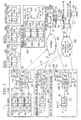
- FIG. 1 is a block diagram showing an example of a battery system according to an exemplary embodiment of the present invention.
- FIG. 2 shows an example of a cartridge battery to the exemplary embodiment of the present invention.
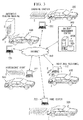
- FIG. 3 shows an example of the battery system according to the exemplary embodiment of the present invention.
- FIG. 4 is a perspective view showing an example of an electric motorcar according to the exemplary embodiment of the present invention.
- FIG. 5 shows an example of the battery system according to the exemplary embodiment of the present invention.
- FIG. 6 shows an example of the battery system according to the exemplary embodiment of the present invention.
- FIG. 7 is a flow chart showing an example of an operation of the battery system according to the exemplary embodiment of the present invention.
- the battery system 1 is provided with an individual residence 100, a shop 200, an automatic vending machine 300, an electric motorcar 500, an electric motorcycle 600, an electric bicycle 700, and an emergency disaster shelter 800, which are respectively present at difference locations.
- a plurality of cartridge batteries 120, 130, and 140 are disposed at the individual residence 100.
- a cartridge battery 210 is disposed at the shop 200 such as convenience store, home center, and charging station.
- a cartridge battery 310 is disposed in the automatic vending machine 300 that sells cartridge batteries.
- a cartridge battery 510 is disposed on the electric motorcar 500.
- a battery 610 is disposed on the electric motorcycle 600.
- a cartridge battery 710 is disposed on the electric bicycle 700.
- a plurality of cartridge batteries 820, 830, and 840 are disposed at the emergency disaster shelter 800.
- the cartridge batteries 120, 130, and 140 are respectively provided with batteries 122, 132, and 142, which are rechargeable type batteries, and housings 123, 133, and 142 that respectively house the batteries 122, 132, and 142.
- the cartridge battery 210 is provided with a battery 212, which is a rechargeable type battery, and a housing 213 that houses the battery 212.
- the cartridge battery 310 is provided with a battery 312, which is a rechargeable type battery, and a housing 313 that houses the battery 312.
- the cartridge battery 510 is provided with a battery 512, which is a rechargeable type battery, and a housing 513 that houses the battery 512.
- the cartridge battery 610 is provided with a battery 612, which is a rechargeable type battery, and a housing 613 that houses the battery 612.
- the cartridge battery 710 is provided with a battery 712, which is a rechargeable type battery, and a housing 713 that houses the battery 712.
- the cartridge batteries 820, 830, and 840 are respectively provided with batteries 822, 832, and 842, which are rechargeable type batteries, and housings 823, 833, and 843 that respectively house the batteries 822, 832, and 842.
- each of the cartridge batteries 120, 130, 140, 210, 310, 510, 610, 710, 820, 830, and 840 is a so-called battery pack that is provided with a rechargeable type battery (secondary battery) and a housing that houses the rechargeable type battery,
- the outer shape and the size of each of the cartridge batteries 120, 130, and 140, the cartridge battery 210, the cartridge battery 310, the cardidge battery 510. the cartridge battery 610, the cartridge battery 710, and the cartridge batteries 820, 830, and 840, are the same and are of the same standard.
- the cartridge batteries 120, 130, 140, 210, 310, 510, 610, 710, 820, 830, and 840 are collectively referred to as cartridge batteries 2.
- batteries 122, 132, 142, 212, 312, 512, 612, 712, 822, 832, and 842 which are rechargeable type batteries, are collectively referred to as batteries 2V.
- housings 2H are collectively referred to as housings 2H.
- the cartridge battery 120 has a cartridge battery identifier (ID) 121.
- the cartridge battery 130 has a cartridge battery ID 131.
- the cartridge battery 140 has a cartridge battery ID 141.
- the cartridge battery 210 has a cartridge battery ID 211,
- the cartridge battery 310 has a cartridge battery ID 311.
- the cartridge battery 510 has a cartridge battery ID 511.
- the cartridge battery 610 has a cartridge battery ID 611.
- the cartridge battery 710 has a cartridge battery ID 711.
- the cartridge battery 820 has a cartridge battery ID 821.
- the cartridge battery 830 has a cartridge battery ID 831.
- the cartridge battery 840 has a cartridge battery ID 841.
- the cartridge batteries 2 are of sufficient size and weight so as to allow easy portability.
- the battery system 1 is disposed at the individual residence 100, and is provided with a charger 150 capable of charging the cartridge batteries 2 (batteries 2V), a charger 220 that is disposed at the shop 200 and is capable of charging the cartridge batteries 2 (batteries 2V), and a charger 320 that is disposed in the automatic vending machine 300 and is capable of charging the cartridge batteries 2 (batteries 2V).
- the battery system 1 is provided with an operating terminal 153 disposed at the individual residence 100, an operating terminal 223 disposed at the shop 200, and at terminal 323 disposes in the automatic vending machine 300.
- the operating terminal 153 is disposed in the charger 150.
- the operating terminal 223 is disposed in the charger 220, and the operating terminal 323 is disposed in the charger 320.
- the charger 150 in addition to the operating terminal 153, has a charging control circuit 151 and a power supply converter 152.
- the charger 220 in addition to the operating terminal 223, has a charging control circuit 221 and a power supply converter 222.
- the charger 320 in addition to the operating terminal 323, has a charging control circuit 321 and a power supply converter 322.
- the individual residence 100 in addition to the charger 150, is provided with a home battery 110, a power supply converter 160, and a solar power generator 170.
- the home battery 110 includes a of the cartridge batteries 120, 130, and 140.
- the automatic vending machine 300 in addition to the charger 320, is provided with a power supply converter 330 and a solar power generator 340.
- the power supply converter 160 of the individual residence 100 through a power transmission/distribution network 980, is connected respectively to a power generator 951 at a nuclear power generating station 950, a power generator 961 at a wind power generating station 960, and a power generator 971 at a hydraulic power generating station 970.
- the power supply converter 222 of the shop 200 through the power transmission/distribution network 980, is connected respectively to the power generator 951 at the nuclear power generating station 950, the power generator 961 at the wind power generating station 960, and the power generator 971 at the hydraulic power generating station 970.
- the power supply converter 330 of the automatic vending machine 300 through the power transmission/distribution network 980, is connected respectively to the power generator 951 at the nuclear power generating station 950, the power generator 961 at the wind power generating station 960, and the power generator 971 at the hydraulic power generating station 970.
- the electric motorcar 500 in addition to the cartridge battery 510, has a main battery 520 and an electric motor 530.
- the main battery 520 equipped on the electric motorcar 500 is fixed on the electric motorcar 500. That is to say, the main battery 520 is a fixed battery in the electric motorcar 500.
- the electric motorcycle 600 in addition to the cartridge battery 610, has an electric motors 620.
- the electric bicycle 700 in addition to the cartridge battery 710, has an electric motor 720.
- the emergency disaster shelter 800 is provided with an emergency battery 810, a power supply converter 850, and an emergency communication device 860.
- the emergency battery 810 includes a plurality of the cartridge batteries 820, 830, and 840.
- the battery system 1 is provided with a management device 900K that manages the cartridge batteries 2.
- the management device 900K is disposed at a battery management center 900 that is present at a location different from the individual residence 100, the shop 200, the automatic vending machine 300, the electric motorcar 500, the electric motorcycle 600, the electric bicycle 700, and the emergency disaster shelter 800.
- the management device 900K includes a management server (battery management server) 910 and a database (battery charging database) 920.
- the management device 900K is capable of managing the cartridge batteries 2 through the Internet (telecommunication line) 400.
- the operating terminal 153 at the individual residence 100 is connected, through the Internet 400, to the management server 910 at the battery management center 900,
- the operating terminal 223 at the shop 200 is connected, through the Internet 400, to the management server 910 at the battery management center 900.
- the operating terminal 323 at the automatic vending machine 300 is connected, through the Internet 400, to the management server 910 at the battery management center 900.
- the cartridge battery ID 121 can output an ID 10 to the operating terminal 153.
- the cartridge battery ID 131 can output the ID 10 to the operating terminal 153
- the cartridge battery ID 141 can output the ID 10 to the operating terminal 153.
- the operating terminal 153 outputs Internet data 11.
- An input of the Internet data 11, via the Internet 400, is received as Internet data 12 on the management server 910 of the management device 900K.
- the management server 910 and the database 920 are connected to each other via a signal cable, and mutually input and output battery management data 13.
- the cartridge battery ID 21 can output an ID 24 to the operating terminal 223.
- the operating terminal 223 outputs Internet data 25.
- An input of the Internet data 25, via the Internet 400, is received as Internet data 12 on the management server 910 of the management device 900K.
- the cartridge battery ID 311 outputs an ID 30 to the operating terminal 323.
- the operating terminal 323 outputs Internet data 31.
- An input of the Internet data 31, via the Internet 400, is received as Internet data 12 on the management server 910 of the management device 900K.
- the power generator 951 at the nuclear power generating station 950 outputs nuclear-generated electric power 15.
- An output of the nuclear-generated electric power 15 from the power generator 951 is received, via the power transmission/distribution network 980, as an input of household power supply 18 to the power supply converter 160 at the individual residence 100.
- an output of the nuclear-generated electric power 15 from the power generator 951 is received, via the power transmission/distribution network 980, as an input of commercial power supply 27 to the power supply converter 222 at the shop 200.
- an output of the nuclear-generated electric power 15 from the power generator 951 is received as an input of commercial power supply 33 to the power supply converter 330 in the automatic vending machine 300.
- the power generator 961 at the wind power generating station 960 outputs wind-generated electric power 16.
- An output of the wind-generated electric power 16 from the power generator 961 is received, via the power transmission/distribution network 980, as an input of household power supply 18 to the power supply converter 160 at the individual residence 100.
- an output of the wind-generated electric power 16 from the power generator 961 is received as an input of commercial power supply 27 to the power supply converter 222 at the shop 200.
- an output of the wind-generated electric power 16 from the power generator 961 is received as an input of commercial power supply 33 to the power supply converter 330 in the automatic vending machine 300.
- the power generator 971 at the hydraulic power generating station 970 outputs hydraulic-generated electric power 17.
- An output of the hydraulic-generated electric power 17 from the power generator 971 is received, via the power transmission/distribution network 980, as an input of household power supply 18 to the power supply converter 160 at the individual residence 100.
- an output of the hydraulic-generated electric power 17 from the power generator 971 is received as an input of commercial power supply 27 to the power supply converter 222 at the shop 200.
- an output of the hydraulic-generated electric power 17 from the power generator 971 is received as an input of commercial power supply 33 to the power supply converter 330 in the cartridge battery automatic vending machine 300.
- the solar power generator 170 At the individual residence 100, if solar light 20 is irradiated on the solar power generator 170, the solar power generator 170 outputs solar-generated electric power 21 to the power supply converter 152.
- the power supply converter 152 outputs cartridge charging power supply (electric power) 22 to the charging control circuit 151.
- the power supply converter 160 outputs cartridge charging power supply (electric power) 19 to the charging control circuit 151.
- the charging control circuit 151 outputs cartridge charging power supply (electric power) 23 respectively to the batteries 122, 132, and 142 of the cartridge batteries 120, 130, and 140 of the home battery 110. Thereby, the batteries 122, 132, and 142 are charged with the electric power 23 supplied from the charging control circuit 151 of the charger 150.
- the charger 150 at the individual residence 100 is capable of charging the batteries 122, 132, and 142, based on at least one of the nuclear-generated electric power 15, the wind-generated electric power 16, the hydraulic-generated electric power 17, and the solar-generated electric power 21.
- the power supply converter 222 outputs cartridge charging power supply (electric power) 28 to the charging control circuit 221.
- the charging control circuit 221 outputs cartridge charging power supply (electric power) 29 to the battery 212 of the cartridge battery 210. Thereby, the battery 212 is charged with the electric power 29 supplied from the charging control circuit 221 of the charger 220.
- the charger 220 at the shop 200 is capable of charging the battery 212, based on at least one of the nuclear-generated electric power 15, the wind-generated electric power 16, and the hydraulic-generated electric power 17.
- the solar power generator 340 In the automatic vending machine 300, if solar light 35 is irradiated on the solar power generator 340, the solar power generator 340 outputs solar-generated electric power 36 to the power supply converter 322.
- the power supply converter 322 outputs cartridge charging power supply (electric power) 37 to the charging control circuit 321.
- the power supply converter 330 outputs cartridge charging power supply (electric power) 34 to the charging control circuit 321.
- the charging control circuit 321 outputs cartridge charging power supply (electric power) 38 to the battery 312 of the cartridge battery 310. Thereby, the battery 312 is charged with the electric power 38 supplied from the charging control circuit 321 of the charger 320.
- the charger 320 in the automatic vending machine 300 is capable of charging the batteries 312, based on at least one of the nuclear-generated electric power 15, the wind-generateal electric power 16, the hydraulic-generated electric power 17, and the solar-generated electric power 36.
- the battery 512 of the cartridge battery 510 can output cartridge battery output driving power supply (electric power) 52 to the electric motor 530.
- the main battery 520 can also output main battery output driving power supply (electric power) 51 to the electric motor 530.
- the battery 612 of the cartridge battery 610 can output cartridge battery output driving power supply (electric power) 53 to the electric motor 620.
- the battery 712 of the cartridge battery 710 can output cartridge battery output driving power supply (electric power) 54 to the electric motor 720.
- the electric motorcar 500 can travel based on the driving power of the electric motor 530.
- the electric motorcar 500 can travel respectively between the individual residence 100, the shop 200, the automatic vending machine 300, and the emergency disaster shelter 800.
- the electric motorcycle 600 can travel based on the driving power of the electric motor 620.
- the electric motorcycle 600 can travel respectively between the individual residence 100, the shop 200, the automatic vending machine 300, and the emergency disaster shelter 800.
- the electric bicycle 700 can travel based on the driving power of the electric motor 720.
- the electric bicycle 700 can travel respectively between the individual residence 100, the shop 200, the automatic vending machine 300, and the emergency disaster shelter 800.
- the electric motorcar 500, the electric motorcycle 600, or the electric bicycle 700 travel in a state where the cartridge battery 2 is equipped on at least one of the electric motorcar 5 00, the electric motorcycle 600, and the electric bicycle 700, the cartridge 2 can travel (be transported) respectively between the individual residence 100, the shop 200, the automatic vending machine 300, and the emergency disaster shelter 800.
- the battery 822 of the cartridge battery 820 of the emergency battery 810 can output cartridge battery output emergency power supply (electric power) 55 to the power supply converter 850 and the emergency communication device 860.
- the battery 832 of the cartridge buttery 830 can output the cartridge battery output emergency power supply (electric power) 55 to the power supply converter 850 and the emergency communication device 860.
- the battery 842 of the cartridge battery 840 can output the cartridge battery output emergency power supply (electric power) 55 to the power supply converter 850 and the emergency communication device 860.
- the power supply converter 850 can output emergency power supply (electric power) 56 based on the electric power 55 from the emergency battery 810. Moreover, the emergency communication device 860 operates based on the electric power 55 from the emergency battery 810 and can thereby output emergency communication data 57.
- FIG. 2 is a diagram showing an example of the cartridge battery 2 according to the present embodiment.
- the cartridge battery 2 is provided with batteries 2V, and a connection section 5 to be releasably connected to a connector 4 of an electrically powered device 3 that operates on electric power.
- the cartridge battery 2 has the connection section 5 thereof connected to the connector 4 of the electrically powered device 3 to thereby supply electric power to the electrically powered device 3.
- the electrically powered device 3 is disposed respectively at the individual residence 100. the shop 200, and the emergency disaster shelter 800, and in the automatic vending machine 300, the electric motorcar 500, the electric motorcycle 600, and the electric bicycle 700.
- the connector 4 is provided on the home battery 110.
- the cartridge battery 2 has the connection section 5 thereof connected to the connector 4, and is capable, via the home battery 110, of supplying electric power to the electrically powered device 3 (such as a home electric appliance or electric equipment) disposed at the individual residence 100.
- the connector 4 may be provided on the home electric appliance or electric equipment, and the connection section 5 may be connected to the connector 4.
- connection section 5 of the cartridge battery 2 has the connection section 5 thereof connected to the connector 4, and is capable of supplying electric power to the electrically powered device 3 disposed at the shop 200 or in the automatic vending machine 300.
- examples of the electrically powered device 3 in the electric motorcar 500, the electric motorcycle 600, and the electric bicycle 700 include the aforementioned electric motors 520, 620, and 720.
- the cartridge battery 2 has the connection section 5 thereof connected to the connector 4 provided on the electric motors 520, 620, and 720 (electrically powered device 3), and is capable of supplying electric power to the electric motors 520, 620, and 720.
- examples of the electrically powered device 3 at the emergency disaster shelter 800 include the aforementioned power supply converter 850 and the emergency communication device 860.
- the cartridge battery 2 has the connection section 5 thereof connected to the connector 4, and is capable, via the emergency battery 810, of supplying electric power to the electrically powered device 3 (the power supply converter 850 and the emergency communication device 860) disposed at the emergency disaster shelter 800.
- the connector 4 may be provided on the power supply converter 850 and the emergency communication device 860, and the connection section 5 may be connected to the connector 4.
- each connector 4 of the electrically powered device 3 respectively at the individual residence 100, the shop 200, and the emergency disaster shelter 800, and in the automatic vending machine 300, the electric motorcar 500, the electric motorcycle 600, and the electric bicycle 700 has the same structure and is of the same standard.
- the outer shape and the size of each of the plurality of cartridge batteries 2 are the same.
- the connection section 5 of each of the plurality of the cartridge batteries 2 has the same structure and is of the same standard. Therefore, the cartridge batteries 2 have the connection section 5 thereof respectively connected to these connectors 4 and are capable of supplying electric power to each electrically powered device 3.
- the connection section 5 is releasably connected to the connector 4, and it is consequently possible to easily replace the cartridge battery 2.
- the operating terminal 153 disposed at the individual residence 100 is described, with reference to the schematic diagram of FIG. 3 .
- the operating terminal 153 is connected, through the Internet 400, to the server 910 at the battery management center 900.
- the operating terminal 153 is provided with a display device 6 such as flat panel display, an input device 7 such as keyboard, and a processing device 8 including a computer.
- the processing device (computer) 8 executes processing based on commands of a program 8P.
- the management device 900K and the processing device 8 are connected to each other through the Internet 400, and are capable of executing transmission and reception of signals and data.
- the display device 6 is capable of displaying output information of the management device 900K output through the Internet 400.
- the display device 6 is capable of displaying information based on signals and data output from the processing device 8 (computer).
- the processing device 8 is provided with a reading function capable of obtaining information of the IDs 121, 131, and 141, and an updating function capable of updating information of the IDs 121, 131, and 141, and it is capable of executing at least either one of obtaining and updating the information of the IDs 121, 131, and 141.
- the management device 900K is capable, through the Internet 400, of executing at least either one of obtaining and updating the information of the IDs 121, 131, and 141.
- the management device 900K through the Internet 400, supplies command signals to the processing device 8, to thereby make the processing device 8 execute at least either one of obtaining and updating the information of the IDs 121, 131, and 141.
- the operating terminal 223 disposed at the shop 200 including a convenience store, home center, and charging station, and the operating terminal 323 disposed in the automatic vending machine 300, are of a configuration similar to that of the operating terminal 153 disposed at the individual residence 100. Therefore, descriptions of the operating terminals 223 and 323 are omitted.
- the management device 900K is capable, through the Internet 400, of executing transmission and reception between the operating terminals 223 and 323, and is capable of supplying command signals to the processing device 8 of the operating terminals 223 and 323.
- the operating terminal 153 at the individual residence 100 reads an ID 10 from the cartridge battery ID 121 of the cartridge battery 120 connected to the charger 150, and transmits, through the Internet 400, the read ID 10 as Internet data 11 to the management server 910 of the management device 900K at the battery management center 900.
- the ID 10 includes information related to the battery 122 of the cartridge battery 120.
- the information related to the battery 122 includes information related to usage history of the cartridge battery 120.
- the information related to the usage history includes information related to charging history of the battery 122.
- the usage history related information includes at least one of a number of charges, an interval of charges, and a time of charges made to the battery 122.
- the cartridge battery ID 121 when the battery 122 is charged, updates and stores the information, related to the history of this charging.
- Pieces of information included in the ID 10 are transmitted, through the Internet 400, from the operating terminal 153 to the management device 900K.
- the information (signal) related to the cartridge battery 2 to be transmitted to the management device 900K by the operating terminal 153 that has read the information included in the ID 10 is appropriately referred to as first information.
- the management device 900K transmits the information related to the cartridge battery 2 to the operating terminal 153 through the Internet 400.
- the information (signal) related to the cartridge battery 2 to be transmitted to the operating terminal 153 by the management device 900K is appropriately referred to as second information.
- the management device 900K based on the received first information (information of the ID 10), transmits, to the operating terminal 153, information related to the battery 122 of the cartridge battery 120 corresponding to the ID 10.
- the second information includes information related to usage history of the cartridge battery 120. That is to say, in the present embodiment, between the operating terminal 153 and the management device 900K, there are transmitted and received the information related to the battery 122 of the cartridge battery 120 and the information related to the usage history of the cartridge battery 120.
- the second information includes information related to the performance of the cartridge battery 120 and risk information.
- the information related to the performance of the cartridge battery 120 includes the amount of accumulated electricity (accumulated electric power) in a case where the battery 122 of the cartridge battery 120 is fully charged.
- the risk information includes information related to the amount of accumulated electricity (remaining amount of accumulated electricity) of the cartridge battery 120. Moreover, the risk information includes information related to the degree of deterioration of the battery 122 because of usage thereof. For example, there is a possibility that the performance of the battery 122 (charging capability and the like) may be deteriorated according to the number, intervals, and time of charging, or to the time of usage. Based on the information related to the usage history of the cartridge battery 120 the number, intervals, and time of charging, or the time of usage, the management device 900K derives the degree of deterioration in the performance (charging capability and the like) of the battery 122, and transmits the derived degree to the operating terminal 153 as the second information. Moreover, based on the information related to the usage history of the cartridge battery 120, the management device 900K transmits information related to the amount of accumulated electricity of the cartridge battery 120 (battery 122) to the operating terminal 153 as the second information.
- the operating terminal 153 displays, on the display device 6, the second information output from the management device 900K.
- the management device 900K is capable of outputting the second information including the risk information not only to the operating terminal 153 but also to the operating terminals 223 and 323 through the Internet 400.
- the first information supplied from the individual residence 100 can be supplied, through the Internet 400, as the second information to the shop 200, the automatic vending machine 300, and the like.
- the management device 900K is capable of deriving risk information based on the usage information of the cartridge battery 120 and the unique information of the battery 122.
- the usage information includes the information related to charging history of the battery 122 (at least one of the number, intervals, and time of charging), the time of usage, and the performance (electric power consumption) of the electrically powered device 3 for which the cartridge battery 120 is to be used.
- the unique information of the battery 122 includes the performance and product type of the battery, and battery information (specification) supplied by a battery maker.
- the usage information for example, holds the ID 10, and the management device 900K is capable of obtaining the usage information based on the ID 10 that is supplied from the operating terminal 153 through the Internet 400.
- the information of the battery 122 is a known value, and is held in the 920.
- the degree of deterioration of the battery 122 according to the usage (usage history) thereof is known information that is preliminarily found, for example, in a preliminary experiment or in a simulation.
- the known information includes information related to the number of charges allowed to be made on the battery 122 while allowing it to maintain the desired performance.
- the known information is stored in the database 920.
- the management device 900K is capable of deriving the degree of deterioration of the battery 122, according to the usage history obtained from the ID 10.
- the management server 910 can on the database 920 for battery information such as charging history information, number of charging cycles (number of charges, intervals of charges, time of charging, and the like), battery product type, and battery maker of the battery 122 indicated by the ID 10 of the Internet data 12 that is transmitted from the operating terminal 153 through the Internet 400, and can output the battery information as the Internet data 12.
- battery information such as charging history information, number of charging cycles (number of charges, intervals of charges, time of charging, and the like), battery product type, and battery maker of the battery 122 indicated by the ID 10 of the Internet data 12 that is transmitted from the operating terminal 153 through the Internet 400, and can output the battery information as the Internet data 12.
- the management server 910 based on the battery information such as the charging history information, number of charging cycles, battery product type, battery maker, and the like of the battery 122, estimates the accumulated electric power and risk in the battery 122 in a case where the battery 122 is fully charged under the conditions found in the battery information, and outputs them as the Internet data 12.
- the battery information such as the charging history information, number of charging cycles, battery product type, battery maker, and the like of the battery 122.
- the management device 900K based on the information related to the history of charging on the battery 122 obtained from the ID 10, outputs, to the operating terminal 153, at least either one of a permitting signal and a non-permitting signal for charging the battery 122.
- the management device 900K based on the information related to charging history and the information related to the number of charges allowed on the battery 122, which is the known information, outputs, to the operating terminal 153, at least either one of a permitting signal and a non-permitting signal.
- the management device 900K compares the information related to the charging history and the information related to the number of allowed charges, and outputs a permitting signal to the operating terminal 153 in a case where the charging history is less than or equal to the number of allowed charges, and outputs a non-permitting signal to the operating terminal 153 in a case where the charging history exceeds the number of allowed charges.
- the management device 900K when outputting a permitting signal, derives an optimal charging method for charging the battery 122, based on the information related to the battery 122 and the information related to the charging history, and outputs, along with the permitting signal, a command signal related to the derived charging method to the operating terminal 153.
- the information related to the battery 122 includes unique information such as the information related to charging history, the type (product type) of the battery 122, and the maker information of the battery 122.
- the charger 150 charges the battery 122 based on the command signal related to the optimal charging method transmitted from the management device 900K to the operating terminal 153. Thereby, the charger 150 can charge the battery 122 with the optimal charging method according to the unique performance of the battery 122.
- the charging control circuit 151 controls the cartridge battery charging power supply 23 according to the instruction of the operating terminal 153 to thereby the battery 122.
- the power supply converter 152 converts the solar-generated electric power 21 generated by the solar power generator 170 into the cartridge battery charging power supply 22 of a power supply method and a voltage suitable for charging the battery 122.
- the power supply converter 160 converts the household power supply 18 into the cartridge battery charging power supply 19 of a power supply method and a voltage suitable for charging the battery 122.
- the operating terminal 153 displays, on the display device 6, the information related to the battery 122 and the information related to the charging history.
- the operating terminal 153 for example, displays at least one of the number of charges, charging intervals, charging time, and degree of deterioration of the battery 122.
- the management device 900K when outputting a non-permitting signal, outputs, along with the non-permitting signal, a command signal for executing recovery of the cartridge battery 120.
- the operating terminal 153 displays, on the display device 6, an indication of instructing execution of recovery.
- the management device 900K is capable of selecting a power generation method to be used for charging the battery 122, based on a signal input received from the input device 7 through the Internet 400.
- the display device 6 displays the result of the selection.
- the management device 900K is capable, based on the signal input received from the input device 7 through the Internet 400, of selecting a period of time for charging the battery 122.
- the display device 6 displays the result of the selection.
- the battery system 1 is capable of executing, on the cartridge batteries 130 and 140, an operation similar to that executed on the cartridge battery 120 with use of the operating terminal 153 and the management device 900K.
- the battery system 1 is capable, with use of the operating terminal 223 and the management device 900K, of executing, on the cartridge battery 210, an operation similar to that executed on the cartridge battery 120 with use of the operating terminal 153 and the management device 900K.
- the battery system I is capable, with use of the operating terminal 323 and the management device 900K, of executing, on the cartridge battery 310, an operation similar to that executed on the cartridge battery 120 with use of the operating terminal 153 and the management device 900K.
- the battery 512 of the cartridge battery 510 can supply cartridge battery output driving power supply (electric power) 52 to the electric motor 530.
- the main battery 520 is capable of supplying the main battery output driving power supply (electric power) 51 to the electric motor 530.
- the electric motor 530 is operated with the supplied electric powers 51 and 52.
- the electric motorcar 500 travels, using the driving power of the electric motor 530.
- the main battery output driving power supply 51 when normally travelling, the main battery output driving power supply 51 is supplied from the battery 520 to the motor 530.
- the electric motor 530 when travelling normally, the electric motor 530 is by the battery 520.
- the cartridge battery output driving power supply (electric power) 52 is supplied from the cartridge battery 510 to the electric motor 530.
- the cartridge battery 510 is replaced with another cartridge battery 2 (such as 610 and 710), and thereby it is to use the electric motorcar 500.
- the electric motorcar 500 can transport the cartridge battery 2 (510) respectively between the individual residence 100, the shop 200, the automatic vending machine 300, and the emergency disaster shelter 800. Moreover, the electric motorcar 500 can have the cartridge battery 2 that was connected at the individual residence 100 for example, replaced at the shop 200 or the like. The electric motorcar 500 is capable of transporting the cartridge battery 2 that was charged at the individual residence 100, for example, to the shop 200.
- the cartridge battery 2 that has been transported is capable of supplying electric power to the electrically powered device 3 disposed at the shop 200.
- the management device 900K based on the usage information of the cartridge battery 2 and the unique information of the cartridge battery 2 obtained from an ID of the cartridge battery 2, is capable of outputting information, related to the amount of accumulated electricity in the cartridge battery 2 and the possible travelling distance of the electric motorcar 500.
- the management device 900K is capable of obtaining usage information of the cartridge battery 2, based on a signal input received from the operating terminal through the Internet 400.
- the information includes information related to time of usage and the structure and performance (weight, electric power consumption, and the like) of the electric motorcar 500.
- the management device 900K based on the amount of accumulated electricity in the cartridge battery 2, the possible traveling distance, and the method of generating electric power (nuclear generation method, hydraulic generation method, wind generation method, solar generation method, and the like) to be used for charging the cartridge battery 2, is capable of deriving a cost (charging cost) required for charging the cartridge battery 2.
- the management device 900K selects a method of generating electric power to be used for charging the cartridge battery 2, and is thereby capable of suppressing the cost.
- the management device 900K selects a period of time (for example, daytime, nighttime, or the like) for charging the cartridge battery 2, and is thereby capable of suppressing the cost.
- the management device 900K selects and commands an optimal charging method for charging the cartridge battery 2, and is thereby capable of suppressing the cost.
- the management device 900K is capable of deriving an amount of CO 2 emission, based on the amount of accumulated electricity in the cartridge battery 2, the possible traveling distance, and the method of generating electric power to be used for charging the cartridge battery 2.
- the management device 900K selects a method of generating electric power to be used for charging the cartridge battery 2, and is thereby capable of suppressing the amount of CO 2 emission.
- the management device 900K selects a period of time for charging the cartridge battery 2, and is thereby capable of suppressing the cost and the amount of CO 2 emission.
- the management device 900K, according to the derived CO 2 emission amount selects and commands an optimal charging method for charging the cartridge battery 2, and is thereby capable of suppressing the cost and the amount of CO 2 emission.
- the management device 900K is capable of outputting information related to the possible traveling distance of the electric motorcar 500, as risk information.
- the management device 900K is capable of deriving risk information based on the usage information of the cartridge battery 2 and the unique information of the cartridge battery 2 obtained from an ID.
- the management device 900K is capable of deriving the risk information, based on ID information (information, related to charging and the like) supplied from the operating terminal through the Internet 400.
- the management device 900K is capable of outputting a command signal to execute recovery of the cartridge battery 2, based on the information related to the history of charging made on the cartridge battery 2, obtained from the ID.
- the cartridge battery 2 with the performance thereof having been deteriorated is excluded from circulation and, for example, sent to the maker of the battery for maintenance or reuse.
- the battery 612 of the cartridge battery 610 supplies cartridge battery output driving power supply (electric power) 61 to the electric motor 620.
- the electric motor 620 is operated with the supplied electric power 61.
- the electric motorcycle 600 travels, using the driving power of the electric motor 620.
- the battery 712 of the cartridge battery 710 supplies cartridge battery output driving power supply (electric power) 71 to the electric motor 720.
- the electric motor 720 is with the supplied electric power 71,
- the electric bicycle 700 travels, using the driving power of the electric motor 720.
- the batteries 822, 832, and 842 of the cartridge batteries 820, 830, and 840 supply cartridge battery output emergency power supply (electric power) 55 to either one of the power supply converter 850 and the emergency communication device 860.
- the power supply converter 850 converts the cartridge battery output emergency power supply 55 into household power supply 56, and outputs it.
- the emergency communication device 860 the cartridge battery output emergency power supply 55 as a power supply, and transmits and receives emergency communication data 57 to thereby perform emergency communications.
- the operating terminal 153 of the cartridge battery charger 150 reads the ID 10 from the cartridge battery ID 121 of the cartridge battery 120 (STEP 1).
- the ID 10 is a unique number or the like assigned to an individual cartridge battery 120.
- the operating terminal 153 converts the read ID 10 into the Internet data 11, and transmits it as the Internet data 12 via the Internet 400 to the management server 910 at the battery management center 900.
- the management server 910 checks the ID 10 from the received Internet data 12 against the battery management data 13 on the database 920 (STEP 2), and reads information related to the battery 122 of the cartridge battery 120 indicated by the ID 10 (STEP 3).
- the information related to the battery 122 includes information related to charging (discharging) history of the battery 122 (number of cycles), and unique information related to the battery 122 (name of maker, name of product, type of product, battery rank, number of allowed charging/discharging cycles, and the like).
- the management server 910 the read information related to the battery 122 as the Internet data 12 through the Internet 400 to be received on the operating terminal 153 as the Internet data 11.
- the operating terminal 153 reads information related to the battery 122 from the received Internet data 11, adds "1 cycle” for the current charging/discharging cycle to the number of charging/discharging cycles, and then compares it with the number of allowed charging/discharging cycles (STEP 4).
- the charging will be commenced and the operating terminal 153 will instruct, with a screen display on the display device6, to select a power generating method (STEP 5Y).
- the operating terminal 153 outputs, to the charging control circuit 151, charging control information 14 that instructs an optimal charging method according to the battery 122 related information (name of maker, name of product, type of product, battery rank, number of allowed charging/discharging cycles, and the like) of the battery 122 to be charged the current number of charging/discharging cycles.
- the battery 122 related information name of maker, name of product, type of product, battery rank, number of allowed charging/discharging cycles, and the like
- the cartridge battery is returned to a recovery agent or battery maker to get the resource recovered, and is reused for a new cartridge battery.
- a power generating method is selected between nuclear power generation, oil-fired power generation, coal-fired power generation, hydraulic power generation, wind power generation, solar power generation, and the like, and use of nighttime use of electric power or the like is selected. For example, in a case where the nuclear power generation and nighttime electric power are selected, then within a period of time in which nighttime electric power is applied, the nuclear-generated electric power 15 generated by the power generator 951 at the nuclear power generating station 950 is converted into the cartridge battery charging power supply 19 by the power supply converter 160, with use of the electric power supplied as the household power supply 18 to the individual residence 100 via the power transmission/distribution network 980, and output to the charging control circuit 151.
- the solar power generation is selected as the power generating method
- charging is performed with use of the solar-generated electric power 21 generated with the solar light 20 irradiated on the solar power generator 170 disposed at the individual residence 100.
- the solar-generated electric power 21 is input to the power supply converter 152 of the cartridge battery charger 150, and converted into the cartridge battery charging power supply 22.
- the cartridge battery charging power supply 22 is output from the power supply converter 152, and input to the charging control 151.
- the charging control circuit 151 charges the battery 122 of the cartridge battery 120 with an optimal charging method according to the charging control information 14 input from the operating terminal 153 (STEP 6 and STEP 7).
- the operating terminal 153 Having completed charging, the operating terminal 153 outputs the charge completion and the power generating method as the Internet data 11, via the Internet 400, to be received on the management server 910 at the battery management center 900 as the Internet data 12.
- the management server 910 adds 1 cycle of the current charging to the charging/discharging history (number of cycles) of the information related to the battery 122 of the cartridge battery 120 indicated by the ID 10 on the database 920, and updates it along with the power generating method.
- the management server 910 calculates the amount of accumulated electricity in the battery and the risk thereof.
- the database 920 has a charging/discharging characteristics database based on battery maker, battery product type, number of charging/discharging cycles, and charging method, and it is possible, if updated information related to the battery 122 (charging/discharging history of the battery (number of cycles), name of maker, name of product, type of product, battery rank, number of allowed charging/discharging cycles, and the like) is given, to calculates the amount of accumulated electricity when fully charged (for example, AH (ampere hour)) and the risk thereof example, %).
- AH ampere hour
- the battery management server 910 transmits the calculated amount of accumulated electricity in the battery and the risk thereof as the Internet date 12, via the Internet 400, to be received on the operating terminal 153 as the Internet data 11.
- the operating terminal 153 reads the amount of accumulated electricity in the battery and the risk thereof from the received Internet data 11, and displays it (STEP 9).
- usage information of the battery 122 to be used purpose of use (electric motorcar, electric motorcycle, or electric bicycle) and the information thereof (name of maker, type of vehicle, name of product, year of make, and the like)).
- the operating terminal 15 reads the ID 10 from the cartridge battery ID 121 of the cartridge battery 120.
- the operating terminal 153 converts the input usage information of the battery 122 and the read ID 10 into the Internet data 11, and transmits it as the Internet data 12 via the Internet 400 to the management server 910 at the battery management center 900.
- the management server 910 checks the usage information of the battery 122 and the ID 10 from the received Internet data 12 against the battery management data 13 on the database 920, and reads information related to the battery 122 of the cartridge battery 120 indicated by the ID 10, the amount of accumulated electricity and the risk thereof.
- the server 910 calculates a possible travelling distance based on the usage information of the battery 122 and the risk thereof.
- the management server 910 transmits the calculated possible travelling distance, the risk thereof, the information related to the battery 122, the amount of accumulated electricity therein, and the risk thereof, as the Internet data 12 through the Internet 400 to be received on the operating terminal 153 ass the Internet data 11.
- the operating terminal 153 reads from the received Internet data 11, the possible traveling distance, the risk thereof, the battery information, the amount of accumulated electricity therein, and the risk thereof, and displays them on the display device 6.
- the operating terminal 153 calculates a charging cost (yen), carbon tax (yen), and CO 2 emission amount (kg) based on the amount of accumulated electricity, the risk thereof, and the power generating method, and displays them on the display device 6 (STEP 10).
- the charging operation and use operation after charging at the shop 200 are also similar to the operation performed at the individual residence 100.
- a number of charged cartridge batteries are available, and a purchaser can freely select and purchase a battery by comparing, on the operating terminal 223, the battery information, possible traveling distance and the risk thereof, cost, carbon tax, and CO 2 emission amount, of each cartridge battery.
- the charging operation and use operation after charging in the case of the cartridge battery automatic vending machine 300 are also similar to the operation performed at the individual residence 100.
- the automatic vending machine 300 As with the shop 200, a number of charged cartridge batteries are available although availability thereof is not as high as that at the shop 200, and a purchaser can freely select and purchase a battery by comparing, on the operating terminal 323, the battery information, possible traveling distance and the risk thereof, cost, carbon tax, and CO 2 emission amount, of each cartridge battery.
- a cartridge battery charged at the individual residence 100, a cartridge battery purchased at the shop 200, and a cartridge battery purchased from the cartridge battery automatic vending machine 300, can be inserted into the electric motorcar 500, the electric motorcycle 600, or the electric bicycle 700, to be thereby used for its intended purpose,
- the electric motorcar 500 it is possible to mount a plurality of the cartridge batteries 510, Moreover, the electric motorcar 500 has, in addition to the battery 512 of the cartridge battery 510, the main battery 520 mounted thereon, and when travelling normally, the main battery 520 supplies the main battery output driving power supply 51 to the electric motor 530 to thereby perform travelling, while the battery 512 of the cartridge battery 510 is used only when the main battery 520 becomes empty.
- the electric motorcycle 600 it is possible to mount a plurality of the cartridge batteries 610.
- a configuration is also possible where a main battery is mounted in addition to the battery 612 of the cartridge battery 610, when traveling normally, the main battery supplies main battery power supply to the electric motor 620 to thereby perform traveling, while the battery 612 of the cartridge battery 610 is used only when the main battery becomes empty.
- the cartridge batteries 820, 830, and 840 there are a plurality of the cartridge batteries 820, 830, and 840, and the emergency battery 810, into which the cartridge batteries 820, 830, and 840 can be inserted, and each user brings and inserts a charged battery for use.
- the cartridge battery is transported on an electric vehicle including at least one of the electric motorcar 700, the electric motorcycle 600, and the electric bicycle 700, and thereby the cartridge battery can be brought in.
- the power supply converter 850 converts the input cartridge battery emergency power supply 55 into the emergency power supple 56 that can be used as household power supply to be used as power supply at the emergency disaster shelter 800.
- the cartridge battery emergency power supply 55 input to the emergency communication device 860 is directly used as power supply for the emergency communication device 860, and the emergency communication device 860 transmits and receives emergency communication data 57, to be thereby utilized for emergency communications.
- the emergency communication device 860 can have a battery directly inserted therein, and can therefore be portably used. Moreover, a used battery is brought into an area not affected by the disaster to be charged, and it can be taken back to be repeatedly used.
- the cartridge battery 2 that is detachable (exchangeable) and easy to transport and that has the same outer shape and size, and it is consequently possible to manufacture a large quantity of only a single type product for various types of applications including not only the electric motorcar 500 but also the electric motorcycle 600, the electric bicycle 700, the home battery 110, and the emergency battery 810. Furthermore, standardization is also possible. If standardization is realized, it will become possible, regardless of maker or product type, to manufacture only a single product type of the cartridge batteries 2, thereby reducing the cost.
- the main battery required for the electric to travel is equipped on the electric motorcar as a large scale fixed battery, and this is complemented by an exchangeable cartridge battery 2 that has a battery capable of accumulating an amount or electric energy only for minimum traveling.
- an exchangeable cartridge battery 2 that has a battery capable of accumulating an amount or electric energy only for minimum traveling.
- a preliminarily charged cartridge battery 2 and a used cartridge battery 2 can be easily and instantly exchanged, and it is consequently possible, even in a case where the battery 2V is empty, to eliminate need for charging time.
- the cartridge battery 2 according to the present embodiment can be easily transported and can be charged anywhere, while allowing a selection of electric power of an energy source of the cartridge that is, electric power of an energy source of the electric motorcar 500, the electric motorcycle 600, the electric bicycle 700, the home battery, and the emergency battery 810. Consequently, with use of carbon-fres electric power or electric power with a low CO 2 emission amount, it is possible to reduce CO 2 emission and thereby reduce carbon tax. Moreover, it is possible to reduce electricity cost using electric power at midnight, and a self-owned solar power generator at an individual residence can be used.
- a plurality of the cartridge batteries 2 according to the present embodiment can be detached, can be easily transported, and have the same outer shape and size, and their battery charging history, the battery information, and the like are centrally managed using individually unique IDs (idantifiers). Consequently, the cartridge battery 2 is such that only the accumulated electric power energy can be purchased and the main body of the cartridge battery 2 is circulated (re-used and circulated), and it is therefore possible to eliminate the need for purchasing an expensive cartridge battery every time.
- a plurality of the, cartridge batteries 2 according to the present embodiment can be detached, can be easily transported, and have same outer shape and size, and it is consequently possible to use the cartridge battery 2 for any one of the cartridge battery of the electric motorcar 500, the cartridge battery of the electric motorcycle 600, the cartridge battery of the electric bicycle 700, the home battery 110,and the emergency battery 810. That is to say, the cartridge battery 2 can be transported and can be made a versatile common standard battery far multiple purposes.
- the cartridge battery 2 can be detached, can be easily transported, and has the same outer shape and size, and it can be charged anywhere and does not require an exchanging facility,
- the cartridge battery 2 can be charged at any one of the individual residence 100, the shop 200 such as convenience store, home center and charging station, and the cartridge battery automatic vending machine 300.
- a charged cartridge battery can be exchanged or purchased.
- the cartridge battery 2 can be exchanged anywhere including a home, convenience store, automatic vending machine, home center, and road.
- the cartridge battery 2 does not require an exchanging facility and can be made a versatile common standard battery, and it can be detached and charged on any electric power.
- the cartridge battery 2 is such that it is detachable, can be transported easily, has the same outer shape, only accumulated electric power energy is to be purchased, and the main body of the cartridge battery is circulated (re-used and circulated), and also the number of charges of all of the cartridge batteries, deterioration in performance, and the like are centrally managed at the battery management center 900. Thereby, it is possible to stop battery-use of all cartridge batteries at an appropriate time with no omission, and to reuse them as resources. Consequently, the cartridge battery .2 enables effective use of resources.
- the cartridge battery 2 can be easily transported, has the same outer and can be charged anywhere, does not require an exchanging facility, and can be detached and charged on any electric power, and consequently energy transportation becomes possible with use of the cartridge battery 2.
- the cartridge battery 2 can be easily transported, does not require an exchanging facility, has the same outer shape, can be detached and charged on any electric power, and can be used anywhere, and it is consequently possible, in the event of a disaster, for individuals to bring and connect a plurality of the cartridge batteries 2 to thereby use them as a large-capacity emergency power supply device, while it is possible, in a case where the batteries are empty, to individually charge them to thereby continuously use them as a large-capacity emergency power supply device.
- the cartridge battery that forms the emergency battery 810. it is possible to use at least one of the cartridge battery 510 used for the electric motorcar 500, the cartridge battery 610 used for the electric motorcycle 600, and the cartridge battery 710 used for the electric bicycle 700.
- the electric motorcar 500 that requites a large capacity
- there may be freely made an optimal design to achieve maximum performance while taking efficiency into consideration in which rather than dividing the main battery required for travelling into plurality of units, only the cartridge battery with a separate battery capable of only accumulating a sufficient amount of electric energy to enable minimum traveling is made exchangeable, and the large-scale/large-capacity main battery required for the electric motorcar 500 to travel is provided as a fixed battery.
- th may be equipped a charger capable the 2V.
- fiXed battery be disposed at the individual residence 100, the shop 200, the automatic vending machine 300, and the like.
- the cartridge battery 2 when electric power supply from the power generating stations 950, 960, 970, the solar power generator, or the fixed battery, to the electrically powered device 3 at the individual residence 100 and the shop 200, and in the automatic vending machine 300 is stopped, is capable of supplying electric power to the electrically powered device 3.
- a cartridge battery is made versatile common standard battery that can be used for multiple purposes such as an electric bicycle battery, an electric motorcycle battery, and a home battery, and thereby it can be applied to many purposes.
- it is normally used as a battery for accumulating energy for home power generation and self power consumption developed in response to CO 2 reduction; it is detached to be used as an electric motorcar battery when using an electric motorcar; it is detached to be used as an electric bicycle battery when using an electric bicycle; and it is detached to be used as an electric motorcycle battery when using an electric motorcycle.
- These ways of use are effective methods of utilization. Therefore, a contribution to industrial development can be made.
- by gathering the cartridge batteries and connecting a number of the cartridge batteries in the event of a disaster they can be used in conjunction for active usage as an important energy source in evacuation life.
Landscapes
- Engineering & Computer Science (AREA)
- Transportation (AREA)
- Business, Economics & Management (AREA)
- Mechanical Engineering (AREA)
- Power Engineering (AREA)
- Economics (AREA)
- Health & Medical Sciences (AREA)
- Water Supply & Treatment (AREA)
- Primary Health Care (AREA)
- Life Sciences & Earth Sciences (AREA)
- Sustainable Development (AREA)
- Sustainable Energy (AREA)
- Electrochemistry (AREA)
- Chemical Kinetics & Catalysis (AREA)
- Chemical & Material Sciences (AREA)
- Public Health (AREA)
- Manufacturing & Machinery (AREA)
- General Health & Medical Sciences (AREA)
- Human Resources & Organizations (AREA)
- Marketing (AREA)
- General Chemical & Material Sciences (AREA)
- Strategic Management (AREA)
- Tourism & Hospitality (AREA)
- Physics & Mathematics (AREA)
- General Business, Economics & Management (AREA)
- General Physics & Mathematics (AREA)
- Theoretical Computer Science (AREA)
- Computer Networks & Wireless Communication (AREA)
- Signal Processing (AREA)
- Charge And Discharge Circuits For Batteries Or The Like (AREA)
- Secondary Cells (AREA)
- Beverage Vending Machines With Cups, And Gas Or Electricity Vending Machines (AREA)
- Battery Mounting, Suspending (AREA)
- Electric Propulsion And Braking For Vehicles (AREA)
Abstract
A management device is configured to obtain information related to the cartridge batteries via a telecommunication line, using an identifier assigned to said cartridge batteries, and to output the obtained information to a predetermined device via said telecommunication line.
Description
- The present invention relates to a cartridge battery, a management device, a battery system, a management method, and a program.
- An electric motorcar travels, using battery electric power as an energy source. There has been proposed, as disclosed in Japanese Unexamined Patent Application, First Publication No.
2001-016706 - There has been a for the smooth supply of electric power not only to electric motorcars but also to various of electrically powered devices that are operated by electric power. With smooth supply of electric power, industrial activities and social activities are smoothly performed, and consequently industrial development can be expected.
- An exemplary object of the present invention is to provide a cartridge battery, a management device, a battery system, a management method, and a program, capable of enabling the smooth execution of industrial activities and social activities.
- According to a exemplary aspect of the present invention, there is provided a cartridge battery that includes a rechargeable battery that can be attached on and detached from an electrically powered device and a charging device, and that is provided with an identifier having information related to usage history thereof.
- A second exemplary aspect of the present invention provides a management device in which information related to a cartridge battery that includes a rechargeable battery that is at least connected to either one of an electrically powered device and a charging device, is obtained, via a telecommunication line, from an identifier provided in the cartridge battery, and the obtained information related to the cartridge battery is output to a predetermined device via the telecommunication line.
- A third exemplary aspect of the present invention provides a battery system that includes; an electrically powered device, a charging device, a cartridge battery of a first exemplary aspect of the present invention, and a management device of a second exemplary aspect of the present invention, in which information related to the cartridge battery is communicated through a telecommunication line.
- A fourth aspect of the present invention provides a method of managing history of a cartridge battery that includes a rechargeable battery, in which the method includes the steps of: storing history of the cartridge battery; updating the stored history; and obtaining the stored history.
- A fifth aspect of the present invention provides a method of managing a cartridge battery that includes a rechargeable battery, in which the method includes the steps of: obtaining information related to usage history from the cartridge battery; displaying information related to performance of the cartridge battery and risk information, based on the obtained information related to the usage history of the cartridge battery; and deriving a cost required for charging the rechargeable battery.
- A sixth aspect of the present invention provides a program for executing on a computer procedures of: storing history of a cartridge battery that includes a rechargeable battery; updating the stored history; and obtaining the stored history.
- A seventh aspect of the present invention provides a program for executing on a computer procedures of: obtaining information related to usage history of a cartridge battery that includes a rechargeable battery; displaying information related to performance of the cartridge battery and risk information, based on the obtained information related to the usage history of the cartridge battery; and deriving a cost required for charging the rechargeable battery.
- According to the present invention, industrial activities and social activities can be smoothly performed.
- Hereunder, an exemplary embodiment of the present invention is described, with reference to the accompanying drawings.
-
FIG. 1 is a block diagram showing an example of a battery system according to an exemplary embodiment of the present invention. -
FIG. 2 shows an example of a cartridge battery to the exemplary embodiment of the present invention. -
FIG. 3 shows an example of the battery system according to the exemplary embodiment of the present invention. -
FIG. 4 is a perspective view showing an example of an electric motorcar according to the exemplary embodiment of the present invention. -
FIG. 5 shows an example of the battery system according to the exemplary embodiment of the present invention. -
FIG. 6 shows an example of the battery system according to the exemplary embodiment of the present invention. -
FIG. 7 is a flow chart showing an example of an operation of the battery system according to the exemplary embodiment of the present invention. - In
FIG. 1 , the battery system 1 is provided with anindividual residence 100, ashop 200, anautomatic vending machine 300, anelectric motorcar 500, anelectric motorcycle 600, anelectric bicycle 700, and anemergency disaster shelter 800, which are respectively present at difference locations. A plurality ofcartridge batteries individual residence 100. Acartridge battery 210 is disposed at theshop 200 such as convenience store, home center, and charging station. Acartridge battery 310 is disposed in theautomatic vending machine 300 that sells cartridge batteries. Acartridge battery 510 is disposed on theelectric motorcar 500. Abattery 610 is disposed on theelectric motorcycle 600. Acartridge battery 710 is disposed on theelectric bicycle 700. A plurality ofcartridge batteries emergency disaster shelter 800. - The
cartridge batteries batteries housings batteries cartridge battery 210 is provided with abattery 212, which is a rechargeable type battery, and ahousing 213 that houses thebattery 212. Thecartridge battery 310 is provided with abattery 312, which is a rechargeable type battery, and ahousing 313 that houses thebattery 312. Thecartridge battery 510 is provided with abattery 512, which is a rechargeable type battery, and a housing 513 that houses thebattery 512. Thecartridge battery 610 is provided with a battery 612, which is a rechargeable type battery, and a housing 613 that houses the battery 612. Thecartridge battery 710 is provided with abattery 712, which is a rechargeable type battery, and ahousing 713 that houses thebattery 712. Thecartridge batteries batteries housings batteries - That is to say, each of the
cartridge batteries - In the present embodiment, the outer shape and the size of each of the
cartridge batteries cartridge battery 210, thecartridge battery 310, thecardidge battery 510. thecartridge battery 610, thecartridge battery 710, and thecartridge batteries cartridge batteries cartridge batteries 2. - Moreover, in the following description, accordingly, the
batteries batteries 2V. - Moreover, in the following description, accordingly, the
housings housings 2H. - Moreover, the cartridge battery 120 has a cartridge battery identifier (ID) 121. The
cartridge battery 130 has acartridge battery ID 131. Thecartridge battery 140 has acartridge battery ID 141. Thecartridge battery 210 has a cartridge battery ID 211, Thecartridge battery 310 has acartridge battery ID 311. Thecartridge battery 510 has acartridge battery ID 511. Thecartridge battery 610 has acartridge battery ID 611. Thecartridge battery 710 has acartridge battery ID 711. Thecartridge battery 820 has acartridge battery ID 821. Thecartridge battery 830 has acartridge battery ID 831. Thecartridge battery 840 has acartridge battery ID 841. - The
cartridge batteries 2 are of sufficient size and weight so as to allow easy portability. - Moreover, the battery system 1 is disposed at the
individual residence 100, and is provided with a charger 150 capable of charging the cartridge batteries 2 (batteries 2V), acharger 220 that is disposed at theshop 200 and is capable of charging the cartridge batteries 2 (batteries 2V), and acharger 320 that is disposed in theautomatic vending machine 300 and is capable of charging the cartridge batteries 2 (batteries 2V). - Moreover, the battery system 1 is provided with an
operating terminal 153 disposed at theindividual residence 100, anoperating terminal 223 disposed at theshop 200, and atterminal 323 disposes in theautomatic vending machine 300. In the present embodiment, theoperating terminal 153 is disposed in the charger 150. Similarly, theoperating terminal 223 is disposed in thecharger 220, and theoperating terminal 323 is disposed in thecharger 320. - Moreover, the charger 150, in addition to the
operating terminal 153, has a charging control circuit 151 and apower supply converter 152. Thecharger 220, in addition to theoperating terminal 223, has acharging control circuit 221 and apower supply converter 222. Thecharger 320, in addition to theoperating terminal 323, has acharging control circuit 321 and apower supply converter 322. - In the embodiment, the
individual residence 100, in addition to the charger 150, is provided with ahome battery 110, apower supply converter 160, and asolar power generator 170. Thehome battery 110 includes a of thecartridge batteries - Moreover, the
automatic vending machine 300, in addition to thecharger 320, is provided with apower supply converter 330 and asolar power generator 340. - The
power supply converter 160 of theindividual residence 100, through a power transmission/distribution network 980, is connected respectively to apower generator 951 at a nuclearpower generating station 950, apower generator 961 at a windpower generating station 960, and apower generator 971 at a hydraulicpower generating station 970. - The
power supply converter 222 of theshop 200, through the power transmission/distribution network 980, is connected respectively to thepower generator 951 at the nuclearpower generating station 950, thepower generator 961 at the windpower generating station 960, and thepower generator 971 at the hydraulicpower generating station 970. - The
power supply converter 330 of theautomatic vending machine 300, through the power transmission/distribution network 980, is connected respectively to thepower generator 951 at the nuclearpower generating station 950, thepower generator 961 at the windpower generating station 960, and thepower generator 971 at the hydraulicpower generating station 970. - The
electric motorcar 500, in addition to thecartridge battery 510, has amain battery 520 and anelectric motor 530. Themain battery 520 equipped on theelectric motorcar 500 is fixed on theelectric motorcar 500. That is to say, themain battery 520 is a fixed battery in theelectric motorcar 500. - The
electric motorcycle 600, in addition to thecartridge battery 610, has an electric motors 620. - The
electric bicycle 700, in addition to thecartridge battery 710, has anelectric motor 720. - The
emergency disaster shelter 800 is provided with anemergency battery 810, apower supply converter 850, and anemergency communication device 860. Theemergency battery 810 includes a plurality of thecartridge batteries - Moreover, the battery system 1 is provided with a
management device 900K that manages thecartridge batteries 2. Themanagement device 900K is disposed at abattery management center 900 that is present at a location different from theindividual residence 100, theshop 200, theautomatic vending machine 300, theelectric motorcar 500, theelectric motorcycle 600, theelectric bicycle 700, and theemergency disaster shelter 800. Themanagement device 900K includes a management server (battery management server) 910 and a database (battery charging database) 920. Themanagement device 900K is capable of managing thecartridge batteries 2 through the Internet (telecommunication line) 400. - The operating
terminal 153 at theindividual residence 100 is connected, through theInternet 400, to themanagement server 910 at thebattery management center 900, - The operating
terminal 223 at theshop 200 is connected, through theInternet 400, to themanagement server 910 at thebattery management center 900. - The operating
terminal 323 at theautomatic vending machine 300 is connected, through theInternet 400, to themanagement server 910 at thebattery management center 900. - At the
individual residence 100, thecartridge battery ID 121 can output anID 10 to theoperating terminal 153. Similarly, thecartridge battery ID 131 can output theID 10 to theoperating terminal 153, and thecartridge battery ID 141 can output theID 10 to theoperating terminal 153. - The operating
terminal 153 outputs Internet data 11. An input of the Internet data 11, via theInternet 400, is received asInternet data 12 on themanagement server 910 of themanagement device 900K. Themanagement server 910 and thedatabase 920 are connected to each other via a signal cable, and mutually input and output battery management data 13. - At the
shop 200, the cartridge battery ID 21 can output anID 24 to theoperating terminal 223. - The operating
terminal 223outputs Internet data 25. An input of theInternet data 25, via theInternet 400, is received asInternet data 12 on themanagement server 910 of themanagement device 900K. - In the
automatic vending machine 300, thecartridge battery ID 311 outputs anID 30 to theoperating terminal 323. The operatingterminal 323outputs Internet data 31. An input of theInternet data 31, via theInternet 400, is received asInternet data 12 on themanagement server 910 of themanagement device 900K. - The
power generator 951 at the nuclearpower generating station 950 outputs nuclear-generatedelectric power 15. An output of the nuclear-generatedelectric power 15 from thepower generator 951 is received, via the power transmission/distribution network 980, as an input ofhousehold power supply 18 to thepower supply converter 160 at theindividual residence 100. - Moreover, an output of the nuclear-generated
electric power 15 from thepower generator 951 is received, via the power transmission/distribution network 980, as an input ofcommercial power supply 27 to thepower supply converter 222 at theshop 200. - Furthermore, an output of the nuclear-generated
electric power 15 from thepower generator 951 is received as an input ofcommercial power supply 33 to thepower supply converter 330 in theautomatic vending machine 300. - Moreover the
power generator 961 at the windpower generating station 960 outputs wind-generatedelectric power 16. An output of the wind-generatedelectric power 16 from thepower generator 961 is received, via the power transmission/distribution network 980, as an input ofhousehold power supply 18 to thepower supply converter 160 at theindividual residence 100. - Furthermore, an output of the wind-generated
electric power 16 from thepower generator 961 is received as an input ofcommercial power supply 27 to thepower supply converter 222 at theshop 200. - Moreover, an output of the wind-generated
electric power 16 from thepower generator 961 is received as an input ofcommercial power supply 33 to thepower supply converter 330 in theautomatic vending machine 300. - Furthermore the
power generator 971 at the hydraulicpower generating station 970 outputs hydraulic-generatedelectric power 17. An output of the hydraulic-generatedelectric power 17 from thepower generator 971 is received, via the power transmission/distribution network 980, as an input ofhousehold power supply 18 to thepower supply converter 160 at theindividual residence 100. - Moreover, an output of the hydraulic-generated
electric power 17 from thepower generator 971 is received as an input ofcommercial power supply 27 to thepower supply converter 222 at theshop 200. - Furthermore, an output of the hydraulic-generated
electric power 17 from thepower generator 971 is received as an input ofcommercial power supply 33 to thepower supply converter 330 in the cartridge batteryautomatic vending machine 300. - At the
individual residence 100, ifsolar light 20 is irradiated on thesolar power generator 170, thesolar power generator 170 outputs solar-generated electric power 21 to thepower supply converter 152. Thepower supply converter 152 outputs cartridge charging power supply (electric power) 22 to the charging control circuit 151. - Moreover, at the
individual residence 100, thepower supply converter 160 outputs cartridge charging power supply (electric power) 19 to the charging control circuit 151. - The charging control circuit 151 outputs cartridge charging power supply (electric power) 23 respectively to the
batteries cartridge batteries home battery 110. Thereby, thebatteries electric power 23 supplied from the charging control circuit 151 of the charger 150. - As described above, in the present embodiment, the charger 150 at the
individual residence 100 is capable of charging thebatteries electric power 15, the wind-generatedelectric power 16, the hydraulic-generatedelectric power 17, and the solar-generated electric power 21. - At the
shop 200, thepower supply converter 222 outputs cartridge charging power supply (electric power) 28 to the chargingcontrol circuit 221. - The charging
control circuit 221 outputs cartridge charging power supply (electric power) 29 to thebattery 212 of thecartridge battery 210. Thereby, thebattery 212 is charged with theelectric power 29 supplied from the chargingcontrol circuit 221 of thecharger 220. - As described above, in the present embodiment, the
charger 220 at theshop 200 is capable of charging thebattery 212, based on at least one of the nuclear-generatedelectric power 15, the wind-generatedelectric power 16, and the hydraulic-generatedelectric power 17. - In the
automatic vending machine 300, if solar light 35 is irradiated on thesolar power generator 340, thesolar power generator 340 outputs solar-generatedelectric power 36 to thepower supply converter 322. Thepower supply converter 322 outputs cartridge charging power supply (electric power) 37 to the chargingcontrol circuit 321. - Moreover, in the
automatic vending machine 3 00, thepower supply converter 330 outputs cartridge charging power supply (electric power) 34 to the chargingcontrol circuit 321. - The charging
control circuit 321 outputs cartridge charging power supply (electric power) 38 to thebattery 312 of thecartridge battery 310. Thereby, thebattery 312 is charged with theelectric power 38 supplied from the chargingcontrol circuit 321 of thecharger 320. - As described above, in the present embodiment, the
charger 320 in theautomatic vending machine 300 is capable of charging thebatteries 312, based on at least one of the nuclear-generatedelectric power 15, the wind-generatealelectric power 16, the hydraulic-generatedelectric power 17, and the solar-generatedelectric power 36. - In the
electric motorcar 500, thebattery 512 of thecartridge battery 510 can output cartridge battery output driving power supply (electric power) 52 to theelectric motor 530. Moreover, themain battery 520 can also output main battery output driving power supply (electric power) 51 to theelectric motor 530. - In the
electric motorcycle 600, the battery 612 of thecartridge battery 610 can output cartridge battery output driving power supply (electric power) 53 to the electric motor 620. - In the
electric bicycle 700, thebattery 712 of thecartridge battery 710 can output cartridge battery output driving power supply (electric power) 54 to theelectric motor 720. - The
electric motorcar 500 can travel based on the driving power of theelectric motor 530. Theelectric motorcar 500 can travel respectively between theindividual residence 100, theshop 200, theautomatic vending machine 300, and theemergency disaster shelter 800. - The
electric motorcycle 600 can travel based on the driving power of the electric motor 620. Theelectric motorcycle 600 can travel respectively between theindividual residence 100, theshop 200, theautomatic vending machine 300, and theemergency disaster shelter 800. - The
electric bicycle 700 can travel based on the driving power of theelectric motor 720. Theelectric bicycle 700 can travel respectively between theindividual residence 100, theshop 200, theautomatic vending machine 300, and theemergency disaster shelter 800. - Therefore, by having the
electric motorcar 500, theelectric motorcycle 600, or theelectric bicycle 700 travel in a state where thecartridge battery 2 is equipped on at least one of theelectric motorcar 5 00, theelectric motorcycle 600, and theelectric bicycle 700, thecartridge 2 can travel (be transported) respectively between theindividual residence 100, theshop 200, theautomatic vending machine 300, and theemergency disaster shelter 800. - At the
emergency disaster shelter 800, thebattery 822 of thecartridge battery 820 of theemergency battery 810 can output cartridge battery output emergency power supply (electric power) 55 to thepower supply converter 850 and theemergency communication device 860. - Similarly, the
battery 832 of thecartridge buttery 830 can output the cartridge battery output emergency power supply (electric power) 55 to thepower supply converter 850 and theemergency communication device 860. - Similarly, the
battery 842 of thecartridge battery 840 can output the cartridge battery output emergency power supply (electric power) 55 to thepower supply converter 850 and theemergency communication device 860. - The
power supply converter 850 can output emergency power supply (electric power) 56 based on theelectric power 55 from theemergency battery 810. Moreover, theemergency communication device 860 operates based on theelectric power 55 from theemergency battery 810 and can thereby outputemergency communication data 57. -
FIG. 2 is a diagram showing an example of thecartridge battery 2 according to the present embodiment. As shown inFIG.2 , thecartridge battery 2 is provided withbatteries 2V, and aconnection section 5 to be releasably connected to aconnector 4 of an electricallypowered device 3 that operates on electric power. Thecartridge battery 2 has theconnection section 5 thereof connected to theconnector 4 of the electricallypowered device 3 to thereby supply electric power to the electricallypowered device 3. - The electrically
powered device 3 is disposed respectively at theindividual residence 100. theshop 200, and theemergency disaster shelter 800, and in theautomatic vending machine 300, theelectric motorcar 500, theelectric motorcycle 600, and theelectric bicycle 700. - At the
individual residence 100, for example, theconnector 4 is provided on thehome battery 110. Thecartridge battery 2 has theconnection section 5 thereof connected to theconnector 4, and is capable, via thehome battery 110, of supplying electric power to the electrically powered device 3 (such as a home electric appliance or electric equipment) disposed at theindividual residence 100. Naturally, theconnector 4 may be provided on the home electric appliance or electric equipment, and theconnection section 5 may be connected to theconnector 4. - Similarly, at the
shop 200 or in theautomatic vending machine 300, to theconnector 4 of the electrically powered device 3 (such as lighting equipment and air conditioning equipment) deposed at theshop 200 or in theautomatic vending machine 300, there is connected theconnection section 5 of thecartridge battery 2. Thecartridge battery 2 has theconnection section 5 thereof connected to theconnector 4, and is capable of supplying electric power to the electricallypowered device 3 disposed at theshop 200 or in theautomatic vending machine 300. - Moreover, examples of the electrically
powered device 3 in theelectric motorcar 500, theelectric motorcycle 600, and theelectric bicycle 700 include the aforementionedelectric motors cartridge battery 2 has theconnection section 5 thereof connected to theconnector 4 provided on theelectric motors 520, 620, and 720 (electrically powered device 3), and is capable of supplying electric power to theelectric motors - Moreover, examples of the electrically
powered device 3 at theemergency disaster shelter 800 include the aforementionedpower supply converter 850 and theemergency communication device 860. In a case where theconnector 4 is provided on theemergency battery 810, thecartridge battery 2 has theconnection section 5 thereof connected to theconnector 4, and is capable, via theemergency battery 810, of supplying electric power to the electrically powered device 3 (thepower supply converter 850 and the emergency communication device 860) disposed at theemergency disaster shelter 800. Naturally, theconnector 4 may be provided on thepower supply converter 850 and theemergency communication device 860, and theconnection section 5 may be connected to theconnector 4. - In the present embodiment, each
connector 4 of the electricallypowered device 3 respectively at theindividual residence 100, theshop 200, and theemergency disaster shelter 800, and in theautomatic vending machine 300, theelectric motorcar 500, theelectric motorcycle 600, and theelectric bicycle 700, has the same structure and is of the same standard. Moreover, as described above, the outer shape and the size of each of the plurality ofcartridge batteries 2, are the same. Moreover, theconnection section 5 of each of the plurality of thecartridge batteries 2, has the same structure and is of the same standard. Therefore, thecartridge batteries 2 have theconnection section 5 thereof respectively connected to theseconnectors 4 and are capable of supplying electric power to each electricallypowered device 3. Moreover, theconnection section 5 is releasably connected to theconnector 4, and it is consequently possible to easily replace thecartridge battery 2. - Next, the operating
terminal 153 disposed at theindividual residence 100 is described, with reference to the schematic diagram ofFIG. 3 . As described above, the operatingterminal 153 is connected, through theInternet 400, to theserver 910 at thebattery management center 900. The operatingterminal 153 is provided with adisplay device 6 such as flat panel display, an input device 7 such as keyboard, and aprocessing device 8 including a computer. In the present embodiment, the processing device (computer) 8 executes processing based on commands of aprogram 8P. Themanagement device 900K and theprocessing device 8 are connected to each other through theInternet 400, and are capable of executing transmission and reception of signals and data. Moreover, thedisplay device 6 is capable of displaying output information of themanagement device 900K output through theInternet 400. Furthermore, thedisplay device 6 is capable of displaying information based on signals and data output from the processing device 8 (computer). - Moreover, the
processing device 8 is provided with a reading function capable of obtaining information of theIDs IDs IDs - Furthermore, the
management device 900K is capable, through theInternet 400, of executing at least either one of obtaining and updating the information of theIDs management device 900K, through theInternet 400, supplies command signals to theprocessing device 8, to thereby make theprocessing device 8 execute at least either one of obtaining and updating the information of theIDs - The operating
terminal 223 disposed at theshop 200 including a convenience store, home center, and charging station, and theoperating terminal 323 disposed in theautomatic vending machine 300, are of a configuration similar to that of the operatingterminal 153 disposed at theindividual residence 100. Therefore, descriptions of the operatingterminals management device 900K is capable, through theInternet 400, of executing transmission and reception between the operatingterminals processing device 8 of the operatingterminals - Next, there is described an example of an operation of the battery system 1 having the configuration described above. Hereunder, there is described an example of an operation concerning the operating
terminal 153 and the cartridge battery 120 at theindividual residence 100. - The operating
terminal 153 at theindividual residence 100 reads anID 10 from thecartridge battery ID 121 of the cartridge battery 120 connected to the charger 150, and transmits, through theInternet 400, theread ID 10 as Internet data 11 to themanagement server 910 of themanagement device 900K at thebattery management center 900. - The
ID 10 includes information related to thebattery 122 of the cartridge battery 120. The information related to thebattery 122 includes information related to usage history of the cartridge battery 120. - The information related to the usage history includes information related to charging history of the
battery 122. - For example, the usage history related information includes at least one of a number of charges, an interval of charges, and a time of charges made to the
battery 122. Thecartridge battery ID 121, when thebattery 122 is charged, updates and stores the information, related to the history of this charging. - These pieces of information included in the
ID 10 are transmitted, through theInternet 400, from the operatingterminal 153 to themanagement device 900K. In the following description, the information (signal) related to thecartridge battery 2 to be transmitted to themanagement device 900K by the operatingterminal 153 that has read the information included in theID 10, is appropriately referred to as first information. - Moreover, in the present embodiment, the
management device 900K transmits the information related to thecartridge battery 2 to theoperating terminal 153 through theInternet 400. In the following description, the information (signal) related to thecartridge battery 2 to be transmitted to theoperating terminal 153 by themanagement device 900K, is appropriately referred to as second information. - The
management device 900K, based on the received first information (information of the ID 10), transmits, to theoperating terminal 153, information related to thebattery 122 of the cartridge battery 120 corresponding to theID 10. The second information includes information related to usage history of the cartridge battery 120. That is to say, in the present embodiment, between the operatingterminal 153 and themanagement device 900K, there are transmitted and received the information related to thebattery 122 of the cartridge battery 120 and the information related to the usage history of the cartridge battery 120. - Moreover, in the present embodiment, the second information includes information related to the performance of the cartridge battery 120 and risk information.
- The information related to the performance of the cartridge battery 120 includes the amount of accumulated electricity (accumulated electric power) in a case where the
battery 122 of the cartridge battery 120 is fully charged. - The risk information includes information related to the amount of accumulated electricity (remaining amount of accumulated electricity) of the cartridge battery 120. Moreover, the risk information includes information related to the degree of deterioration of the
battery 122 because of usage thereof. For example, there is a possibility that the performance of the battery 122 (charging capability and the like) may be deteriorated according to the number, intervals, and time of charging, or to the time of usage. Based on the information related to the usage history of the cartridge battery 120 the number, intervals, and time of charging, or the time of usage, themanagement device 900K derives the degree of deterioration in the performance (charging capability and the like) of thebattery 122, and transmits the derived degree to theoperating terminal 153 as the second information. Moreover, based on the information related to the usage history of the cartridge battery 120, themanagement device 900K transmits information related to the amount of accumulated electricity of the cartridge battery 120 (battery 122) to theoperating terminal 153 as the second information. - The operating
terminal 153 displays, on thedisplay device 6, the second information output from themanagement device 900K. - Moreover, the
management device 900K is capable of outputting the second information including the risk information not only to theoperating terminal 153 but also to the operatingterminals Internet 400. Thus, the first information supplied from theindividual residence 100 can be supplied, through theInternet 400, as the second information to theshop 200, theautomatic vending machine 300, and the like. - The
management device 900K is capable of deriving risk information based on the usage information of the cartridge battery 120 and the unique information of thebattery 122. The usage information includes the information related to charging history of the battery 122 (at least one of the number, intervals, and time of charging), the time of usage, and the performance (electric power consumption) of the electricallypowered device 3 for which the cartridge battery 120 is to be used. The unique information of thebattery 122 includes the performance and product type of the battery, and battery information (specification) supplied by a battery maker. The usage information, for example, holds theID 10, and themanagement device 900K is capable of obtaining the usage information based on theID 10 that is supplied from the operatingterminal 153 through theInternet 400. Moreover, the information of thebattery 122 is a known value, and is held in the 920. - In the present embodiment, the degree of deterioration of the
battery 122 according to the usage (usage history) thereof is known information that is preliminarily found, for example, in a preliminary experiment or in a simulation. The known information includes information related to the number of charges allowed to be made on thebattery 122 while allowing it to maintain the desired performance. The known information is stored in thedatabase 920. Themanagement device 900K is capable of deriving the degree of deterioration of thebattery 122, according to the usage history obtained from theID 10. - For example, the
management server 910 can on thedatabase 920 for battery information such as charging history information, number of charging cycles (number of charges, intervals of charges, time of charging, and the like), battery product type, and battery maker of thebattery 122 indicated by theID 10 of theInternet data 12 that is transmitted from the operatingterminal 153 through theInternet 400, and can output the battery information as theInternet data 12. - Moreover, the
management server 910, based on the battery information such as the charging history information, number of charging cycles, battery product type, battery maker, and the like of thebattery 122, estimates the accumulated electric power and risk in thebattery 122 in a case where thebattery 122 is fully charged under the conditions found in the battery information, and outputs them as theInternet data 12. - The
management device 900K, based on the information related to the history of charging on thebattery 122 obtained from theID 10, outputs, to theoperating terminal 153, at least either one of a permitting signal and a non-permitting signal for charging thebattery 122. - That is to say, the
management device 900K, based on the information related to charging history and the information related to the number of charges allowed on thebattery 122, which is the known information, outputs, to theoperating terminal 153, at least either one of a permitting signal and a non-permitting signal. - The
management device 900K compares the information related to the charging history and the information related to the number of allowed charges, and outputs a permitting signal to theoperating terminal 153 in a case where the charging history is less than or equal to the number of allowed charges, and outputs a non-permitting signal to theoperating terminal 153 in a case where the charging history exceeds the number of allowed charges. - In the present embodiment, the
management device 900K, when outputting a permitting signal, derives an optimal charging method for charging thebattery 122, based on the information related to thebattery 122 and the information related to the charging history, and outputs, along with the permitting signal, a command signal related to the derived charging method to theoperating terminal 153. Here, the information related to thebattery 122 includes unique information such as the information related to charging history, the type (product type) of thebattery 122, and the maker information of thebattery 122. The charger 150 charges thebattery 122 based on the command signal related to the optimal charging method transmitted from themanagement device 900K to theoperating terminal 153. Thereby, the charger 150 can charge thebattery 122 with the optimal charging method according to the unique performance of thebattery 122. - In the charging method, for example, the amount of the
electric power 23 supplied from the charging control circuit 151 to thebattery 122, the time of charging, and the like, are designated. For example, the charging control circuit 151 controls the cartridge battery chargingpower supply 23 according to the instruction of the operatingterminal 153 to thereby thebattery 122. In the present embodiment, thepower supply converter 152 converts the solar-generated electric power 21 generated by thesolar power generator 170 into the cartridge battery chargingpower supply 22 of a power supply method and a voltage suitable for charging thebattery 122. Moreover, thepower supply converter 160 converts thehousehold power supply 18 into the cartridge battery charging power supply 19 of a power supply method and a voltage suitable for charging thebattery 122. - Moreover, the operating
terminal 153 displays, on thedisplay device 6, the information related to thebattery 122 and the information related to the charging history. The operatingterminal 153, for example, displays at least one of the number of charges, charging intervals, charging time, and degree of deterioration of thebattery 122. - On the other hand, the
management device 900K, when outputting a non-permitting signal, outputs, along with the non-permitting signal, a command signal for executing recovery of the cartridge battery 120. The operatingterminal 153 displays, on thedisplay device 6, an indication of instructing execution of recovery. Thereby, the cartridge battery 120 with the performance thereof having been deteriorated is excluded from circulation and, for example, sent to the maker of thebattery 122 for maintenance or reuse. By recovering the cartridge battery, resource recovery is possible. - In the present embodiment, the
management device 900K is capable of selecting a power generation method to be used for charging thebattery 122, based on a signal input received from the input device 7 through theInternet 400. Thedisplay device 6 displays the result of the selection. - Moreover, the
management device 900K is capable, based on the signal input received from the input device 7 through theInternet 400, of selecting a period of time for charging thebattery 122. Thedisplay device 6 displays the result of the selection. - In the above description, there has been described above an example of an operation that is on the cartridge battery 120, using the
operating terminal 153 at theindividual residence 100 and themanagement device 900K. The battery system 1 is capable of executing, on thecartridge batteries terminal 153 and themanagement device 900K. - Moreover, the battery system 1 is capable, with use of the operating
terminal 223 and themanagement device 900K, of executing, on thecartridge battery 210, an operation similar to that executed on the cartridge battery 120 with use of the operatingterminal 153 and themanagement device 900K. - Furthermore, the battery system I is capable, with use of the operating
terminal 323 and themanagement device 900K, of executing, on thecartridge battery 310, an operation similar to that executed on the cartridge battery 120 with use of the operatingterminal 153 and themanagement device 900K. - Next, an example of an operation of the
electric motorcar 500 is described, with reference toFIG. 1 ,FIG. 4 , andFIG. 5 . In theelectric motorcar 500, thebattery 512 of thecartridge battery 510 can supply cartridge battery output driving power supply (electric power) 52 to theelectric motor 530. Moreover, in theelectric motorcar 500, themain battery 520 is capable of supplying the main battery output driving power supply (electric power) 51 to theelectric motor 530. Theelectric motor 530 is operated with the supplied electric powers 51 and 52. Theelectric motorcar 500 travels, using the driving power of theelectric motor 530. - In the
electric motorcar 500 of the present embodiment, when normally travelling, the main battery output driving power supply 51 is supplied from thebattery 520 to themotor 530. In the electric 500, when travelling normally, theelectric motor 530 is by thebattery 520. On the other hand, when supply of electric power from themain battery 520 is stopped, for example, in a case where themain battery 520 has become empty, the cartridge battery output driving power supply (electric power) 52 is supplied from thecartridge battery 510 to theelectric motor 530. - Moreover, when the
main battery 520 has been used and become completely empty, and also when thecartridge battery 510 has been used and become completely empty, thecartridge battery 510 is replaced with another cartridge battery 2 (such as 610 and 710), and thereby it is to use theelectric motorcar 500. - The
electric motorcar 500 can transport the cartridge battery 2 (510) respectively between theindividual residence 100, theshop 200, theautomatic vending machine 300, and theemergency disaster shelter 800. Moreover, theelectric motorcar 500 can have thecartridge battery 2 that was connected at theindividual residence 100 for example, replaced at theshop 200 or the like. Theelectric motorcar 500 is capable of transporting thecartridge battery 2 that was charged at theindividual residence 100, for example, to theshop 200. - The
cartridge battery 2 that has been transported is capable of supplying electric power to the electricallypowered device 3 disposed at theshop 200. - The
management device 900K, based on the usage information of thecartridge battery 2 and the unique information of thecartridge battery 2 obtained from an ID of thecartridge battery 2, is capable of outputting information, related to the amount of accumulated electricity in thecartridge battery 2 and the possible travelling distance of theelectric motorcar 500. - The
management device 900K is capable of obtaining usage information of thecartridge battery 2, based on a signal input received from the operating terminal through theInternet 400. - Here, the information includes information related to time of usage and the structure and performance (weight, electric power consumption, and the like) of the
electric motorcar 500. - The
management device 900K, based on the amount of accumulated electricity in thecartridge battery 2, the possible traveling distance, and the method of generating electric power (nuclear generation method, hydraulic generation method, wind generation method, solar generation method, and the like) to be used for charging thecartridge battery 2, is capable of deriving a cost (charging cost) required for charging thecartridge battery 2. Themanagement device 900K, according to the derived cost, selects a method of generating electric power to be used for charging thecartridge battery 2, and is thereby capable of suppressing the cost. Moreover, themanagement device 900K, according to the derived cost, selects a period of time (for example, daytime, nighttime, or the like) for charging thecartridge battery 2, and is thereby capable of suppressing the cost. - Furthermore, the
management device 900K, according to the derived cost, selects and commands an optimal charging method for charging thecartridge battery 2, and is thereby capable of suppressing the cost. - Moreover, the
management device 900K is capable of deriving an amount of CO2 emission, based on the amount of accumulated electricity in thecartridge battery 2, the possible traveling distance, and the method of generating electric power to be used for charging thecartridge battery 2. Themanagement device 900K, according to the derived CO2 emission amount, selects a method of generating electric power to be used for charging thecartridge battery 2, and is thereby capable of suppressing the amount of CO2 emission. Furthermore, themanagement device 900K, according to the derived CO2 emission amount, selects a period of time for charging thecartridge battery 2, and is thereby capable of suppressing the cost and the amount of CO2 emission. Moreover, themanagement device 900K, according to the derived CO2 emission amount, selects and commands an optimal charging method for charging thecartridge battery 2, and is thereby capable of suppressing the cost and the amount of CO2 emission. - As for the
electric motorcar 500, themanagement device 900K is capable of outputting information related to the possible traveling distance of theelectric motorcar 500, as risk information. Themanagement device 900K is capable of deriving risk information based on the usage information of thecartridge battery 2 and the unique information of thecartridge battery 2 obtained from an ID. As described above, themanagement device 900K is capable of deriving the risk information, based on ID information (information, related to charging and the like) supplied from the operating terminal through theInternet 400. Themanagement device 900K is capable of outputting a command signal to execute recovery of thecartridge battery 2, based on the information related to the history of charging made on thecartridge battery 2, obtained from the ID. Thereby, thecartridge battery 2 with the performance thereof having been deteriorated is excluded from circulation and, for example, sent to the maker of the battery for maintenance or reuse. - Next, an example of an operation of the
electric motorcycle 600 is described. In theelectric motorcycle 600, the battery 612 of thecartridge battery 610 supplies cartridge battery output driving power supply (electric power) 61 to the electric motor 620. The electric motor 620 is operated with the supplied electric power 61. Theelectric motorcycle 600 travels, using the driving power of the electric motor 620. - Next, an example of an operation of the
electric bicycle 700 is described. In theelectric bicycle 700, thebattery 712 of thecartridge battery 710 supplies cartridge battery output driving power supply (electric power) 71 to theelectric motor 720. Theelectric motor 720 is with the supplied electric power 71, Theelectric bicycle 700 travels, using the driving power of theelectric motor 720. - Next, an example of an operation of the
cartridge battery 820 at theemergency disaster shelter 800 is described, with reference toFIG. 1 andFIG. 6 . At theemergency disaster shelter 800, thebatteries cartridge batteries power supply converter 850 and theemergency communication device 860. - The
power supply converter 850 converts the cartridge battery outputemergency power supply 55 intohousehold power supply 56, and outputs it. Theemergency communication device 860 the cartridge battery outputemergency power supply 55 as a power supply, and transmits and receivesemergency communication data 57 to thereby perform emergency communications. - Next, there is described in detail an operation of the entire battery system 1 according to the present embodiment, with reference to
FIG. 1 to FIG. 7 . - First, there is described, with reference to the flow chart in
FIG. 7 , an operation in a case of charging the cartridge battery 120 of thehome battery 110 at theindividual residence 100. - The operating
terminal 153 of the cartridge battery charger 150 reads theID 10 from thecartridge battery ID 121 of the cartridge battery 120 (STEP 1). - The
ID 10 is a unique number or the like assigned to an individual cartridge battery 120. - Next, the operating
terminal 153 converts theread ID 10 into the Internet data 11, and transmits it as theInternet data 12 via theInternet 400 to themanagement server 910 at thebattery management center 900. - The
management server 910 checks theID 10 from the receivedInternet data 12 against the battery management data 13 on the database 920 (STEP 2), and reads information related to thebattery 122 of the cartridge battery 120 indicated by the ID 10 (STEP 3). - In the present embodiment, the information related to the
battery 122 includes information related to charging (discharging) history of the battery 122 (number of cycles), and unique information related to the battery 122 (name of maker, name of product, type of product, battery rank, number of allowed charging/discharging cycles, and the like). - The
management server 910 the read information related to thebattery 122 as theInternet data 12 through theInternet 400 to be received on theoperating terminal 153 as the Internet data 11. - The operating
terminal 153 reads information related to thebattery 122 from the received Internet data 11, adds "1 cycle" for the current charging/discharging cycle to the number of charging/discharging cycles, and then compares it with the number of allowed charging/discharging cycles (STEP 4). - If "the number of charging/discharging cycles is less than or equal to the number of allowed charging/discharging cycles", the charging will be commenced and the
operating terminal 153 will instruct, with a screen display on the display device6, to select a power generating method (STEP 5Y). - On the other hand, based on the received information related to the
battery 122, the operatingterminal 153 outputs, to the charging control circuit 151, charging control information 14 that instructs an optimal charging method according to thebattery 122 related information (name of maker, name of product, type of product, battery rank, number of allowed charging/discharging cycles, and the like) of thebattery 122 to be charged the current number of charging/discharging cycles. - If "the number of charging/discharging cycles is greater than number of allowed charging/discharging cycles", charging will be impossible and the
operating terminal 153 will onscreen-display on thedisplay device 6 that charging is impossible, and will display a screen to instruct recovery of the battery (STEP 5N). - In a case where recovery of the battery is instructed, the cartridge battery is returned to a recovery agent or battery maker to get the resource recovered, and is reused for a new cartridge battery.
- In the selection of a power generating method, a power generating method is selected between nuclear power generation, oil-fired power generation, coal-fired power generation, hydraulic power generation, wind power generation, solar power generation, and the like, and use of nighttime use of electric power or the like is selected. For example, in a case where the nuclear power generation and nighttime electric power are selected, then within a period of time in which nighttime electric power is applied, the nuclear-generated
electric power 15 generated by thepower generator 951 at the nuclearpower generating station 950 is converted into the cartridge battery charging power supply 19 by thepower supply converter 160, with use of the electric power supplied as thehousehold power supply 18 to theindividual residence 100 via the power transmission/distribution network 980, and output to the charging control circuit 151. - Moreover, in a case where the solar power generation is selected as the power generating method, charging is performed with use of the solar-generated electric power 21 generated with the
solar light 20 irradiated on thesolar power generator 170 disposed at theindividual residence 100. The solar-generated electric power 21 is input to thepower supply converter 152 of the cartridge battery charger 150, and converted into the cartridge battery chargingpower supply 22. - The cartridge battery charging
power supply 22 is output from thepower supply converter 152, and input to the charging control 151. The charging control circuit 151 charges thebattery 122 of the cartridge battery 120 with an optimal charging method according to the charging control information 14 input from the operating terminal 153 (STEP 6 and STEP 7). - Having completed charging, the operating
terminal 153 outputs the charge completion and the power generating method as the Internet data 11, via theInternet 400, to be received on themanagement server 910 at thebattery management center 900 as theInternet data 12. - The
management server 910 adds 1 cycle of the current charging to the charging/discharging history (number of cycles) of the information related to thebattery 122 of the cartridge battery 120 indicated by theID 10 on thedatabase 920, and updates it along with the power generating method. - The
management server 910, according to the updated information related to the battery 122 (charging/discharging history of the battery (number of cycles), name of maker, name of product, type of product, battery rank, number of allowed charging/discharging cycles, and the like) and thedatabase 920, calculates the amount of accumulated electricity in the battery and the risk thereof. - The
database 920 has a charging/discharging characteristics database based on battery maker, battery product type, number of charging/discharging cycles, and charging method, and it is possible, if updated information related to the battery 122 (charging/discharging history of the battery (number of cycles), name of maker, name of product, type of product, battery rank, number of allowed charging/discharging cycles, and the like) is given, to calculates the amount of accumulated electricity when fully charged (for example, AH (ampere hour)) and the risk thereof example, %). - The
battery management server 910 transmits the calculated amount of accumulated electricity in the battery and the risk thereof as theInternet date 12, via theInternet 400, to be received on theoperating terminal 153 as the Internet data 11. - The operating
terminal 153 reads the amount of accumulated electricity in the battery and the risk thereof from the received Internet data 11, and displays it (STEP 9). - In the above description, there has been described the operation of charging the cartridge battery 120 of the
home battery 110 at theindividual residence 100. - Next, there is described, with reference to the flow chart in
FIG. 7 , an operation in a case of using the cartridge battery 120 of thehome battery 110 at theindividual residence 100 that has charged. - First, on the
operating terminal 153, there is input usage information of thebattery 122 to be used (purpose of use (electric motorcar, electric motorcycle, or electric bicycle) and the information thereof (name of maker, type of vehicle, name of product, year of make, and the like)). - The operating
terminal 15 3, as with the case of charging, reads theID 10 from thecartridge battery ID 121 of the cartridge battery 120. - Next, the operating
terminal 153 converts the input usage information of thebattery 122 and theread ID 10 into the Internet data 11, and transmits it as theInternet data 12 via theInternet 400 to themanagement server 910 at thebattery management center 900. - The
management server 910 checks the usage information of thebattery 122 and theID 10 from the receivedInternet data 12 against the battery management data 13 on thedatabase 920, and reads information related to thebattery 122 of the cartridge battery 120 indicated by theID 10, the amount of accumulated electricity and the risk thereof. - The
server 910, based on the usage of the battery 122 (purpose of use (electric motorcar, electric motorcycle, or electric bicycle) and the information thereof (name of maker, type of vehicle, name of product, year of make, and the like)), the information related to thebattery 122, the amount of accumulated electricity therein, and the risk thereof, calculates a possible travelling distance based on the usage information of thebattery 122 and the risk thereof. - The
management server 910 transmits the calculated possible travelling distance, the risk thereof, the information related to thebattery 122, the amount of accumulated electricity therein, and the risk thereof, as theInternet data 12 through theInternet 400 to be received on theoperating terminal 153 ass the Internet data 11. - The operating
terminal 153, reads from the received Internet data 11, the possible traveling distance, the risk thereof, the battery information, the amount of accumulated electricity therein, and the risk thereof, and displays them on thedisplay device 6. - Moreover, the operating
terminal 153 calculates a charging cost (yen), carbon tax (yen), and CO2 emission amount (kg) based on the amount of accumulated electricity, the risk thereof, and the power generating method, and displays them on the display device 6 (STEP 10). - In the above description; there has been described the operation in a case of using the cartridge battery 120 of the
home battery 110 at theindividual residence 100 that has been charged. - The charging operation and use operation after charging at the
shop 200 such as a convenience store, home center, and charging station, are also similar to the operation performed at theindividual residence 100. - At the 200, a number of charged cartridge batteries are available, and a purchaser can freely select and purchase a battery by comparing, on the
operating terminal 223, the battery information, possible traveling distance and the risk thereof, cost, carbon tax, and CO2 emission amount, of each cartridge battery. - When purchasing a cartridge battery at the
shop 200, a purchase cannot be made unless a used cartridge battery is recovered in exchange. - On the other hand, the charging operation and use operation after charging in the case of the cartridge battery
automatic vending machine 300, are also similar to the operation performed at theindividual residence 100. - In the
automatic vending machine 300, as with theshop 200, a number of charged cartridge batteries are available although availability thereof is not as high as that at theshop 200, and a purchaser can freely select and purchase a battery by comparing, on theoperating terminal 323, the battery information, possible traveling distance and the risk thereof, cost, carbon tax, and CO2 emission amount, of each cartridge battery. - When purchasing a cartridge battery from the
automatic vending machine 300, a new charged cartridge battery cannot be purchased unless a used cartridge battery is inserted. - Moreover, it is possible to automatically charge the recovered used cartridge batteries with use of the
solar power generator 340 to thereby repeatedly sell them. - In the above description, there have been described the operation at the time of charging and the operation at the time of purchasing a charged battery, at the
shop 200 such as convenience store, home center, and charging station, and at the cartridge batteryautomatic vending machine 300. - A cartridge battery charged at the
individual residence 100, a cartridge battery purchased at theshop 200, and a cartridge battery purchased from the cartridge batteryautomatic vending machine 300, can be inserted into theelectric motorcar 500, theelectric motorcycle 600, or theelectric bicycle 700, to be thereby used for its intended purpose, - In a case of the
electric motorcar 500, it is possible to mount a plurality of thecartridge batteries 510, Moreover, theelectric motorcar 500 has, in addition to thebattery 512 of thecartridge battery 510, themain battery 520 mounted thereon, and when travelling normally, themain battery 520 supplies the main battery output driving power supply 51 to theelectric motor 530 to thereby perform travelling, while thebattery 512 of thecartridge battery 510 is used only when themain battery 520 becomes empty. - Also in a case of the
electric motorcycle 600, it is possible to mount a plurality of thecartridge batteries 610. Moreover, in a case of a largeelectric motorcycle 600, as with theelectric motorcar 500, a configuration is also possible where a main battery is mounted in addition to the battery 612 of thecartridge battery 610, when traveling normally, the main battery supplies main battery power supply to the electric motor 620 to thereby perform traveling, while the battery 612 of thecartridge battery 610 is used only when the main battery becomes empty. - In a case of the
electric bicycle 700, as with the case of a current electric bicycle, traveling is possible only by inserting thecartridge battery 710. - At the
emergency disaster shelter 800, there are a plurality of thecartridge batteries emergency battery 810, into which thecartridge batteries electric motorcar 700, theelectric motorcycle 600, and theelectric bicycle 700, and thereby the cartridge battery can be brought in. - The cartridge battery
emergency power supply 55 output from thebatteries cartridge batteries power supply converter 850 and theemergency communication 860. - The
power supply converter 850 converts the input cartridge batteryemergency power supply 55 into the emergency power supple 56 that can be used as household power supply to be used as power supply at theemergency disaster shelter 800. - Moreover, the cartridge battery
emergency power supply 55 input to theemergency communication device 860 is directly used as power supply for theemergency communication device 860, and theemergency communication device 860 transmits and receivesemergency communication data 57, to be thereby utilized for emergency communications. - The
emergency communication device 860 can have a battery directly inserted therein, and can therefore be portably used. Moreover, a used battery is brought into an area not affected by the disaster to be charged, and it can be taken back to be repeatedly used. - As described above, according to the present embodiment, there is used the
cartridge battery 2 that is detachable (exchangeable) and easy to transport and that has the same outer shape and size, and it is consequently possible to manufacture a large quantity of only a single type product for various types of applications including not only theelectric motorcar 500 but also theelectric motorcycle 600, theelectric bicycle 700, thehome battery 110, and theemergency battery 810. Furthermore, standardization is also possible. If standardization is realized, it will become possible, regardless of maker or product type, to manufacture only a single product type of thecartridge batteries 2, thereby reducing the cost. - Moreover, in the present embodiment, in a case of operating an electric motorcar or large electric motorcycle that require a large capacity and takes a large scale battery, for example, the main battery required for the electric to travel is equipped on the electric motorcar as a large scale fixed battery, and this is complemented by an
exchangeable cartridge battery 2 that has a battery capable of accumulating an amount or electric energy only for minimum traveling. Thus, it is possible to reduce the size of thecartridge battery 2. Consequently, anyone including the owner of the electric motorcar can easily replace thecartridge battery 2 without an exchange facility. - Moreover, a preliminarily charged
cartridge battery 2 and a usedcartridge battery 2 can be easily and instantly exchanged, and it is consequently possible, even in a case where thebattery 2V is empty, to eliminate need for charging time. - Furthermore, the
cartridge battery 2 according to the present embodiment can be easily transported and can be charged anywhere, while allowing a selection of electric power of an energy source of the cartridge that is, electric power of an energy source of theelectric motorcar 500, theelectric motorcycle 600, theelectric bicycle 700, the home battery, and theemergency battery 810. Consequently, with use of carbon-fres electric power or electric power with a low CO2 emission amount, it is possible to reduce CO2 emission and thereby reduce carbon tax. Moreover, it is possible to reduce electricity cost using electric power at midnight, and a self-owned solar power generator at an individual residence can be used. - Moreover, a plurality of the
cartridge batteries 2 according to the present embodiment can be detached, can be easily transported, and have the same outer shape and size, and their battery charging history, the battery information, and the like are centrally managed using individually unique IDs (idantifiers). Consequently, thecartridge battery 2 is such that only the accumulated electric power energy can be purchased and the main body of thecartridge battery 2 is circulated (re-used and circulated), and it is therefore possible to eliminate the need for purchasing an expensive cartridge battery every time. - Moreover, a plurality of the,
cartridge batteries 2 according to the present embodiment can be detached, can be easily transported, and have same outer shape and size, and it is consequently possible to use thecartridge battery 2 for any one of the cartridge battery of theelectric motorcar 500, the cartridge battery of theelectric motorcycle 600, the cartridge battery of theelectric bicycle 700, thehome battery 110,and theemergency battery 810. That is to say, thecartridge battery 2 can be transported and can be made a versatile common standard battery far multiple purposes. - Moreover, according to the present embodiment, the
cartridge battery 2 can be detached, can be easily transported, and has the same outer shape and size, and it can be charged anywhere and does not require an exchanging facility, - Furthermore, the
cartridge battery 2 can be charged at any one of theindividual residence 100, theshop 200 such as convenience store, home center and charging station, and the cartridge batteryautomatic vending machine 300. A charged cartridge battery can be exchanged or purchased. Moreover, thecartridge battery 2 can be exchanged anywhere including a home, convenience store, automatic vending machine, home center, and road. Thus, thecartridge battery 2 does not require an exchanging facility and can be made a versatile common standard battery, and it can be detached and charged on any electric power. - Furthermore, the
cartridge battery 2 is such that it is detachable, can be transported easily, has the same outer shape, only accumulated electric power energy is to be purchased, and the main body of the cartridge battery is circulated (re-used and circulated), and also the number of charges of all of the cartridge batteries, deterioration in performance, and the like are centrally managed at thebattery management center 900. Thereby, it is possible to stop battery-use of all cartridge batteries at an appropriate time with no omission, and to reuse them as resources. Consequently, the cartridge battery .2 enables effective use of resources. - Moreover, the
cartridge battery 2 can be easily transported, has the same outer and can be charged anywhere, does not require an exchanging facility, and can be detached and charged on any electric power, and consequently energy transportation becomes possible with use of thecartridge battery 2. - Furthermore, the
cartridge battery 2 can be easily transported, does not require an exchanging facility, has the same outer shape, can be detached and charged on any electric power, and can be used anywhere, and it is consequently possible, in the event of a disaster, for individuals to bring and connect a plurality of thecartridge batteries 2 to thereby use them as a large-capacity emergency power supply device, while it is possible, in a case where the batteries are empty, to individually charge them to thereby continuously use them as a large-capacity emergency power supply device. - Moreover, as the cartridge battery that forms the
emergency battery 810. it is possible to use at least one of thecartridge battery 510 used for theelectric motorcar 500, thecartridge battery 610 used for theelectric motorcycle 600, and thecartridge battery 710 used for theelectric bicycle 700. - Furthermore, in a case of the
electric motorcar 500 that requites a large capacity, there may be freely made an optimal design to achieve maximum performance while taking efficiency into consideration, in which rather than dividing the main battery required for travelling into plurality of units, only the cartridge battery with a separate battery capable of only accumulating a sufficient amount of electric energy to enable minimum traveling is made exchangeable, and the large-scale/large-capacity main battery required for theelectric motorcar 500 to travel is provided as a fixed battery. - In the embodiment described above, on at least one of the
electric motorcar 500, theelectric motorcycle 600, and theelectric bicycle 700, th may be equipped a charger capable the 2V. - In the embodiment described above fiXed battery be disposed at the
individual residence 100, theshop 200, theautomatic vending machine 300, and the like. Thecartridge battery 2, when electric power supply from thepower generating stations powered device 3 at theindividual residence 100 and theshop 200, and in theautomatic vending machine 300 is stopped, is capable of supplying electric power to the electricallypowered device 3. - According to the present invention, a cartridge battery is made versatile common standard battery that can be used for multiple purposes such as an electric bicycle battery, an electric motorcycle battery, and a home battery, and thereby it can be applied to many purposes. Particularly it is normally used as a battery for accumulating energy for home power generation and self power consumption developed in response to CO2 reduction; it is detached to be used as an electric motorcar battery when using an electric motorcar; it is detached to be used as an electric bicycle battery when using an electric bicycle; and it is detached to be used as an electric motorcycle battery when using an electric motorcycle. These ways of use are effective methods of utilization. Therefore, a contribution to industrial development can be made. Moreover, by gathering the cartridge batteries and connecting a number of the cartridge batteries in the event of a disaster, they can be used in conjunction for active usage as an important energy source in evacuation life.
- The present application claims priority on Japanese Patent Application No.
2008-281255, filed October 31, 2008
Claims (12)
- A cartridge battery comprising a rechargeable battery that can be attached on and detached from an electrically powered device and a charging device, and an identifier showing information related to usage history of said rechargeable battery.
- A management device comprising a server configured to obtain information related to a cartridge battery that includes a rechargeable battery that is at least connected to either one of an electrically powered device and a charging device via a telecommunication line using an identifier assigned to said cartridge battery, and to output the obtained information related to said cartridge battery to a predetermined device via said telecommunication line.
- A management device according to claim 2, wherein said information related to a cartridge battery includes at least one of: information related to usage history of said cartridge battery, and risk information, of said cartridge battery caused by usage thereof.
- A management device according to claim 3, wherein said information related to usage history includes at least one of: a number of charges, an interval of charges, and a time of charges.
- A management device according to claim 3 or 4, wherein said risk information includes information related to a degree of deterioration of said cartridge battery caused by usage thereof.
- A management device according to claim 2, 3, 4 or 5, wherein said electrically powered device is an electric vehicle that travels by means of electric power from said cartridge battery, and said management device calculates a cost required for charging said rechargeable battery based on; an amount of accumulated electricity in said rechargeable battery, a possible traveling distance of said electric vehicle, and a method of generating electric power to be used for charging said rechargeable battery.
- A management device according to claim 6, wherein said management device calculates an amount of CO2 emission based on; an amount of accumulated electricity in said rechargeable battery, a possible traveling distance of said electric vehicle, and a method of generating electric power to be used for charging said rechargeable battery.
- A battery system comprising;
an electrically powered device,
a charging device,
said cartridge battery according to claim 1, and
said management device according to claim 2,
in which information related to said cartridge battery is communicated through a telecommunication line. - A method of managing history of a cartridge battery that includes a rechargeable battery, comprising:storing history of said cartridge battery in a memory;updating said stored history in said memory; andobtaining said stored history from said memory.
- A method of managing a cartridge battery that includes a rechargeable battery, said method comprising:obtaining information related to usage history from said cartridge battery;displaying information related to performance of said cartridge battery and risk information, based on the obtained information related to the usage history of said cartridge battery; andderiving a cost required for charging said rechargeable battery.
- A program for executing on a computer procedures of:storing history of a cartridge battery that includes a rechargeable battery in a memory;updating said stored history in said memory; andobtaining said stored history from said memory.
- A program for executing on a computer procedures of:obtaining information related to usage history of a cartridge battery that includes a rechargeable battery;displaying information related to performance of said cartridge battery and risk information, based on the obtained information related to the usage history of said cartridge battery; andderiving a cost required for charging said rechargeable battery.
Applications Claiming Priority (1)
| Application Number | Priority Date | Filing Date | Title |
|---|---|---|---|
| JP2008281255A JP5509577B2 (en) | 2008-10-31 | 2008-10-31 | Charging device, management device, battery system, battery management method, and battery management program |
Publications (2)
| Publication Number | Publication Date |
|---|---|
| EP2182575A1 true EP2182575A1 (en) | 2010-05-05 |
| EP2182575B1 EP2182575B1 (en) | 2017-03-08 |
Family
ID=41600598
Family Applications (1)
| Application Number | Title | Priority Date | Filing Date |
|---|---|---|---|
| EP09174502.6A Active EP2182575B1 (en) | 2008-10-31 | 2009-10-29 | Cartridge battery, management device, battery system, management method, and program |
Country Status (4)
| Country | Link |
|---|---|
| US (1) | US20100114800A1 (en) |
| EP (1) | EP2182575B1 (en) |
| JP (1) | JP5509577B2 (en) |
| CN (1) | CN101728566B (en) |
Cited By (19)
| Publication number | Priority date | Publication date | Assignee | Title |
|---|---|---|---|---|
| US20130113424A1 (en) * | 2011-09-29 | 2013-05-09 | Michael Lynn Froelich | Temperature-controlled external battery charger and standardized, manually-changable modular battery system for electric-powered vehicles and craft |
| EP2737599A4 (en) * | 2011-07-26 | 2015-09-02 | Apparatus, method and article for authentication, security and control of power storage devices, such as batteries, based on user profiles | |
| US9216687B2 (en) | 2012-11-16 | 2015-12-22 | Gogoro Inc. | Apparatus, method and article for vehicle turn signals |
| US9407024B2 (en) | 2014-08-11 | 2016-08-02 | Gogoro Inc. | Multidirectional electrical connector, plug and system |
| US9424697B2 (en) | 2011-07-26 | 2016-08-23 | Gogoro Inc. | Apparatus, method and article for a power storage device compartment |
| US9437058B2 (en) | 2011-07-26 | 2016-09-06 | Gogoro Inc. | Dynamically limiting vehicle operation for best effort economy |
| US9552682B2 (en) | 2011-07-26 | 2017-01-24 | Gogoro Inc. | Apparatus, method and article for redistributing power storage devices, such as batteries, between collection, charging and distribution machines |
| CN107278349A (en) * | 2016-02-03 | 2017-10-20 | 松下知识产权经营株式会社 | The control method and server unit of server unit |
| US9830753B2 (en) | 2011-07-26 | 2017-11-28 | Gogoro Inc. | Apparatus, method and article for reserving power storage devices at reserving power storage device collection, charging and distribution machines |
| US9911252B2 (en) | 2011-07-26 | 2018-03-06 | Gogoro Inc. | Apparatus, method and article for providing to a user device information regarding availability of portable electrical energy storage devices at a portable electrical energy storage device collection, charging and distribution machine |
| US10040359B2 (en) | 2014-09-04 | 2018-08-07 | Gogoro Inc. | Apparatus, system, and method for vending, charging, and two-way distribution of electrical energy storage devices |
| US10186094B2 (en) | 2011-07-26 | 2019-01-22 | Gogoro Inc. | Apparatus, method and article for providing locations of power storage device collection, charging and distribution machines |
| US10209090B2 (en) | 2011-07-26 | 2019-02-19 | Gogoro Inc. | Apparatus, method and article for authentication, security and control of power storage devices, such as batteries |
| US10345843B2 (en) | 2011-07-26 | 2019-07-09 | Gogoro Inc. | Apparatus, method and article for redistributing power storage devices, such as batteries, between collection, charging and distribution machines |
| GB2570870A (en) * | 2018-01-31 | 2019-08-14 | Pilot Subs | An electric vehicle and a method of recharging an electric vehicle |
| US10421462B2 (en) | 2015-06-05 | 2019-09-24 | Gogoro Inc. | Systems and methods for vehicle load detection and response |
| US11075530B2 (en) | 2013-03-15 | 2021-07-27 | Gogoro Inc. | Modular system for collection and distribution of electric storage devices |
| US11222485B2 (en) | 2013-03-12 | 2022-01-11 | Gogoro Inc. | Apparatus, method and article for providing information regarding a vehicle via a mobile device |
| US11581752B2 (en) | 2018-11-29 | 2023-02-14 | Honda Motor Co., Ltd. | Battery charging system, charging device, information processing device, battery charging method, program, and storage medium |
Families Citing this family (48)
| Publication number | Priority date | Publication date | Assignee | Title |
|---|---|---|---|---|
| WO2011118607A1 (en) * | 2010-03-24 | 2011-09-29 | 三洋電機株式会社 | Power supply device, power storage device, and power control device |
| US20110302078A1 (en) | 2010-06-02 | 2011-12-08 | Bryan Marc Failing | Managing an energy transfer between a vehicle and an energy transfer system |
| JP5393602B2 (en) * | 2010-07-01 | 2014-01-22 | 株式会社日立製作所 | Power control method, program, and power control apparatus |
| JP2012029518A (en) * | 2010-07-27 | 2012-02-09 | Yukio Kurokawa | Electric car battery utilization system |
| JP5350349B2 (en) | 2010-09-30 | 2013-11-27 | 株式会社エヌ・ティ・ティ・ドコモ | Power generation apparatus, portable device, power generation method identification system, power generation method identification method |
| WO2013001909A1 (en) * | 2011-06-30 | 2013-01-03 | 三洋電機株式会社 | Battery charger and power supply apparatus |
| US9129461B2 (en) | 2011-07-26 | 2015-09-08 | Gogoro Inc. | Apparatus, method and article for collection, charging and distributing power storage devices, such as batteries |
| US8560147B2 (en) | 2011-07-26 | 2013-10-15 | Gogoro, Inc. | Apparatus, method and article for physical security of power storage devices in vehicles |
| JP2013090548A (en) * | 2011-10-21 | 2013-05-13 | Honda Motor Co Ltd | Vehicular power storage system |
| JP2013115863A (en) * | 2011-11-25 | 2013-06-10 | Honda Motor Co Ltd | Battery management system |
| JP5888952B2 (en) * | 2011-12-01 | 2016-03-22 | 株式会社日立製作所 | Regional energy management method |
| JP5247874B2 (en) * | 2011-12-06 | 2013-07-24 | パナソニック株式会社 | Storage battery transfer support device and storage battery transfer support method |
| JP5683506B2 (en) * | 2012-01-19 | 2015-03-11 | 株式会社日本総合研究所 | Energy management system and energy management method |
| JP2013183521A (en) * | 2012-03-01 | 2013-09-12 | Hitachi Ltd | Device, method, and program of controlling distributed power supply by using movable type power storage medium |
| JP2013215016A (en) * | 2012-03-30 | 2013-10-17 | Toshiba Corp | Power supply system |
| US9748778B2 (en) | 2012-08-24 | 2017-08-29 | Panasonic Intellectual Property Management Co., Ltd. | Power supply apparatus |
| US9381826B2 (en) | 2012-10-19 | 2016-07-05 | Gogoro Inc. | Battery configuration for an electric vehicle |
| CN105191056A (en) | 2013-03-12 | 2015-12-23 | 睿能创意公司 | Apparatus, method and article for changing portable electrical power storage device exchange plans |
| US9440544B2 (en) | 2013-03-15 | 2016-09-13 | Columbia Insurance Company | Battery management system and method |
| CN105829160B (en) | 2013-08-06 | 2017-10-24 | 睿能创意公司 | The use of single or multiple battery units is the system and method that electric car is powered |
| CN108189701B (en) | 2013-08-06 | 2021-10-22 | 睿能创意公司 | Electric vehicle system based on thermal profile adjustment of electric energy storage device |
| JP6695800B2 (en) | 2013-08-30 | 2020-05-20 | ゴゴロ インク | Portable electric energy storage device with thermal runaway mitigation |
| CN104670036B (en) * | 2013-11-28 | 2021-08-06 | 松下电器(美国)知识产权公司 | Information output method and information output system |
| ES2721000T3 (en) | 2014-01-23 | 2019-07-26 | Gogoro Inc | Systems and methods for using a set of energy storage devices, such as batteries |
| WO2015115069A1 (en) * | 2014-01-31 | 2015-08-06 | パナソニックIpマネジメント株式会社 | Information provision method, information provision apparatus, and battery pack |
| CN105264710B (en) * | 2014-02-13 | 2019-01-04 | 松下知识产权经营株式会社 | Battery packet and charging unit |
| WO2016006152A1 (en) | 2014-07-11 | 2016-01-14 | パナソニックIpマネジメント株式会社 | Storage battery pack, and storage battery pack operation method |
| CN112026552B (en) * | 2014-09-02 | 2021-10-01 | 葛炽昌 | Electric power maintaining method for electric vehicle |
| USD789883S1 (en) | 2014-09-04 | 2017-06-20 | Gogoro Inc. | Collection, charging and distribution device for portable electrical energy storage devices |
| USD820197S1 (en) | 2014-10-03 | 2018-06-12 | Gogoro Inc. | Portable electrical energy storage device with components |
| JP6332066B2 (en) * | 2015-02-06 | 2018-05-30 | Jfeエンジニアリング株式会社 | Portable battery management system and waste disposal system |
| US9825345B2 (en) | 2015-02-27 | 2017-11-21 | Gogoro Inc. | Portable electrical energy storage device with in-situ formable fluid channels |
| JP2016208692A (en) * | 2015-04-23 | 2016-12-08 | イモア株式会社 | On-vehicle battery system |
| US10153475B2 (en) | 2015-05-11 | 2018-12-11 | Gogoro Inc. | Electrical connector for portable multi-cell electrical energy storage device |
| JP6830309B2 (en) * | 2015-05-11 | 2021-02-17 | 日本信号株式会社 | Battery supply device and parking system including it |
| CN105070961B (en) * | 2015-07-30 | 2017-08-29 | 山东梅拉德能源动力科技有限公司 | A kind of echelon application process of battery standard module |
| WO2017058722A1 (en) | 2015-10-01 | 2017-04-06 | Gogoro Inc. | Frame for portable electrical energy storage cells |
| CA3019622A1 (en) * | 2016-04-01 | 2018-02-15 | Power Hero Corp. | An automated system for managing and providing a network of charging stations |
| US11796340B2 (en) * | 2017-04-03 | 2023-10-24 | Power Hero Corp. | Universal automated system for identifying, registering and verifying the existence, location and characteristics of electric and other power outlets by random users and for retrieval and utilization of such parametric data and outlets by all users |
| JP7032110B2 (en) * | 2017-11-21 | 2022-03-08 | トヨタ自動車株式会社 | Exchange charge setting device and exchange charge setting system |
| US10579098B2 (en) * | 2017-12-14 | 2020-03-03 | Disney Enterprises, Inc. | Inferring the transfer of a physical object associated with a wearable device |
| CN108255220A (en) * | 2018-02-02 | 2018-07-06 | 宁波力芯科信息科技有限公司 | A kind of outdoor agricultural management system based on wireless charging |
| JP2021119555A (en) * | 2018-03-20 | 2021-08-12 | 本田技研工業株式会社 | Management device, battery, and management system |
| CN111902993A (en) * | 2018-03-26 | 2020-11-06 | 京瓷株式会社 | Control device, information processing device, and storage battery search system |
| CN109017382B (en) * | 2018-08-01 | 2021-09-28 | 奇瑞汽车股份有限公司 | Battery management method and device for electric vehicle and storage medium |
| TWI723566B (en) * | 2019-10-04 | 2021-04-01 | 映興電子股份有限公司 | Operation method of smart distribution off-peak power |
| JP6972235B1 (en) * | 2020-05-26 | 2021-11-24 | エヌ・ティ・ティ・コミュニケーションズ株式会社 | Product information management equipment, methods and programs |
| CN115965363B (en) * | 2023-03-16 | 2023-06-02 | 苏州时代华景新能源有限公司 | Lithium battery energy storage box operation data processing method and system |
Citations (7)
| Publication number | Priority date | Publication date | Assignee | Title |
|---|---|---|---|---|
| JPH05227669A (en) * | 1992-02-14 | 1993-09-03 | Tatsuno Co Ltd | Battery charger for electric automobile |
| JP2001016706A (en) | 1999-01-01 | 2001-01-19 | Ryuzo Shimizu | Detachable battery in electric vehicle |
| US20030114105A1 (en) * | 2001-12-18 | 2003-06-19 | Amit Haller | Method, system and computer readable medium for making a business decision in response to information from a short distance wireless network |
| WO2003098908A1 (en) * | 2002-05-21 | 2003-11-27 | Philip Bernard Wesby | System and method for remote asset management |
| US20050048359A1 (en) * | 2002-10-29 | 2005-03-03 | Sanyo Electric Co., Ltd. | Battery, device and charger |
| JP2005339187A (en) * | 2004-05-27 | 2005-12-08 | Tokyo Electric Power Co Inc:The | Information processing method for specifying carbon dioxide emission reduction amount |
| WO2007105579A1 (en) * | 2006-03-13 | 2007-09-20 | Toyota Jidosha Kabushiki Kaisha | Vehicle and electric apparatus |
Family Cites Families (20)
| Publication number | Priority date | Publication date | Assignee | Title |
|---|---|---|---|---|
| JPH04334906A (en) * | 1991-05-08 | 1992-11-24 | Honda Motor Co Ltd | Electric motor vehicle with auxiliary power source |
| US5711648A (en) * | 1994-01-06 | 1998-01-27 | Unlimited Range Electric Car Systems Company | Battery charging and transfer system |
| US5803215A (en) * | 1997-01-22 | 1998-09-08 | Schott Power Systems Incorporated | Method and apparatus for charging a plurality of electric vehicles |
| US6265091B1 (en) * | 1997-06-06 | 2001-07-24 | Johnson Controls Technology Company | Modular electric storage battery |
| JPH11313075A (en) * | 1998-04-28 | 1999-11-09 | Matsushita Electric Works Ltd | Information supply management system |
| US20030209375A1 (en) * | 1999-01-25 | 2003-11-13 | Zip Charge Corporation | Electrical vehicle energy supply system, electrical vehicle battery, electrical vehicle battery charging apparatus, battery supply apparatus, and electrical vehicle battery management system |
| SE515927C2 (en) * | 1999-01-27 | 2001-10-29 | Ericsson Telefon Ab L M | A method and apparatus for identifying a battery |
| JP3878397B2 (en) * | 2000-07-19 | 2007-02-07 | 九州電力株式会社 | Secondary battery full charge, battery deterioration degree and dischargeable capacity determination method and apparatus |
| JP2003007348A (en) * | 2001-06-20 | 2003-01-10 | Sony Computer Entertainment Inc | Battery providing system and battery providing method |
| JP2004210230A (en) * | 2003-01-08 | 2004-07-29 | Toshiba Eng Co Ltd | Electrically assisted bicycle and rental method of electrically assisted bicycle |
| US7446503B2 (en) * | 2004-08-10 | 2008-11-04 | Illinois Tool Works Inc. | Method and apparatus for charging batteries using a converter |
| JP2006302733A (en) * | 2005-04-22 | 2006-11-02 | Matsushita Electric Ind Co Ltd | Battery pack and its connection system |
| JP5078119B2 (en) * | 2005-12-06 | 2012-11-21 | トヨタ自動車株式会社 | Charger |
| JP4747929B2 (en) * | 2006-04-24 | 2011-08-17 | 新神戸電機株式会社 | Battery inspection system |
| CN100481607C (en) * | 2006-05-10 | 2009-04-22 | 财团法人工业技术研究院 | Intelligent electric vehicle power supply display system |
| JP2008029071A (en) * | 2006-07-19 | 2008-02-07 | Honda Motor Co Ltd | Motor-driven vehicle |
| US7844370B2 (en) * | 2006-08-10 | 2010-11-30 | Gridpoint, Inc. | Scheduling and control in a power aggregation system for distributed electric resources |
| US20080110683A1 (en) * | 2006-11-10 | 2008-05-15 | Alexander Serkh | Plug-in hybrid accessory drive system |
| JP5013833B2 (en) * | 2006-12-05 | 2012-08-29 | 株式会社日立製作所 | Home battery control device, home battery control system, in-vehicle battery control system, home battery control method, and in-vehicle battery control method |
| JP2008226758A (en) * | 2007-03-15 | 2008-09-25 | Seiko Epson Corp | Charge management device, control method for the same, and control program |
-
2008
- 2008-10-31 JP JP2008281255A patent/JP5509577B2/en active Active
-
2009
- 2009-10-28 CN CN200910209126.9A patent/CN101728566B/en active Active
- 2009-10-29 US US12/588,833 patent/US20100114800A1/en not_active Abandoned
- 2009-10-29 EP EP09174502.6A patent/EP2182575B1/en active Active
Patent Citations (7)
| Publication number | Priority date | Publication date | Assignee | Title |
|---|---|---|---|---|
| JPH05227669A (en) * | 1992-02-14 | 1993-09-03 | Tatsuno Co Ltd | Battery charger for electric automobile |
| JP2001016706A (en) | 1999-01-01 | 2001-01-19 | Ryuzo Shimizu | Detachable battery in electric vehicle |
| US20030114105A1 (en) * | 2001-12-18 | 2003-06-19 | Amit Haller | Method, system and computer readable medium for making a business decision in response to information from a short distance wireless network |
| WO2003098908A1 (en) * | 2002-05-21 | 2003-11-27 | Philip Bernard Wesby | System and method for remote asset management |
| US20050048359A1 (en) * | 2002-10-29 | 2005-03-03 | Sanyo Electric Co., Ltd. | Battery, device and charger |
| JP2005339187A (en) * | 2004-05-27 | 2005-12-08 | Tokyo Electric Power Co Inc:The | Information processing method for specifying carbon dioxide emission reduction amount |
| WO2007105579A1 (en) * | 2006-03-13 | 2007-09-20 | Toyota Jidosha Kabushiki Kaisha | Vehicle and electric apparatus |
Cited By (24)
| Publication number | Priority date | Publication date | Assignee | Title |
|---|---|---|---|---|
| US10186094B2 (en) | 2011-07-26 | 2019-01-22 | Gogoro Inc. | Apparatus, method and article for providing locations of power storage device collection, charging and distribution machines |
| US11139684B2 (en) | 2011-07-26 | 2021-10-05 | Gogoro Inc. | Apparatus, method and article for a power storage device compartment |
| US10055911B2 (en) | 2011-07-26 | 2018-08-21 | Gogoro Inc. | Apparatus, method and article for authentication, security and control of power storage devices, such as batteries, based on user profiles |
| US10546438B2 (en) | 2011-07-26 | 2020-01-28 | Gogoro Inc. | Apparatus, method and article for providing vehicle diagnostic data |
| US9424697B2 (en) | 2011-07-26 | 2016-08-23 | Gogoro Inc. | Apparatus, method and article for a power storage device compartment |
| US9437058B2 (en) | 2011-07-26 | 2016-09-06 | Gogoro Inc. | Dynamically limiting vehicle operation for best effort economy |
| US9552682B2 (en) | 2011-07-26 | 2017-01-24 | Gogoro Inc. | Apparatus, method and article for redistributing power storage devices, such as batteries, between collection, charging and distribution machines |
| US10529151B2 (en) | 2011-07-26 | 2020-01-07 | Gogoro Inc. | Apparatus, method and article for reserving power storage devices at reserving power storage device collection, charging and distribution machines |
| US9830753B2 (en) | 2011-07-26 | 2017-11-28 | Gogoro Inc. | Apparatus, method and article for reserving power storage devices at reserving power storage device collection, charging and distribution machines |
| US9911252B2 (en) | 2011-07-26 | 2018-03-06 | Gogoro Inc. | Apparatus, method and article for providing to a user device information regarding availability of portable electrical energy storage devices at a portable electrical energy storage device collection, charging and distribution machine |
| US10459471B2 (en) | 2011-07-26 | 2019-10-29 | Gorogo Inc. | Apparatus, method and article for collection, charging and distributing power storage devices, such as batteries |
| EP2737599A4 (en) * | 2011-07-26 | 2015-09-02 | Apparatus, method and article for authentication, security and control of power storage devices, such as batteries, based on user profiles | |
| US10345843B2 (en) | 2011-07-26 | 2019-07-09 | Gogoro Inc. | Apparatus, method and article for redistributing power storage devices, such as batteries, between collection, charging and distribution machines |
| US10209090B2 (en) | 2011-07-26 | 2019-02-19 | Gogoro Inc. | Apparatus, method and article for authentication, security and control of power storage devices, such as batteries |
| US20130113424A1 (en) * | 2011-09-29 | 2013-05-09 | Michael Lynn Froelich | Temperature-controlled external battery charger and standardized, manually-changable modular battery system for electric-powered vehicles and craft |
| US9216687B2 (en) | 2012-11-16 | 2015-12-22 | Gogoro Inc. | Apparatus, method and article for vehicle turn signals |
| US11222485B2 (en) | 2013-03-12 | 2022-01-11 | Gogoro Inc. | Apparatus, method and article for providing information regarding a vehicle via a mobile device |
| US11075530B2 (en) | 2013-03-15 | 2021-07-27 | Gogoro Inc. | Modular system for collection and distribution of electric storage devices |
| US9407024B2 (en) | 2014-08-11 | 2016-08-02 | Gogoro Inc. | Multidirectional electrical connector, plug and system |
| US10040359B2 (en) | 2014-09-04 | 2018-08-07 | Gogoro Inc. | Apparatus, system, and method for vending, charging, and two-way distribution of electrical energy storage devices |
| US10421462B2 (en) | 2015-06-05 | 2019-09-24 | Gogoro Inc. | Systems and methods for vehicle load detection and response |
| CN107278349A (en) * | 2016-02-03 | 2017-10-20 | 松下知识产权经营株式会社 | The control method and server unit of server unit |
| GB2570870A (en) * | 2018-01-31 | 2019-08-14 | Pilot Subs | An electric vehicle and a method of recharging an electric vehicle |
| US11581752B2 (en) | 2018-11-29 | 2023-02-14 | Honda Motor Co., Ltd. | Battery charging system, charging device, information processing device, battery charging method, program, and storage medium |
Also Published As
| Publication number | Publication date |
|---|---|
| JP5509577B2 (en) | 2014-06-04 |
| US20100114800A1 (en) | 2010-05-06 |
| JP2010108833A (en) | 2010-05-13 |
| EP2182575B1 (en) | 2017-03-08 |
| CN101728566A (en) | 2010-06-09 |
| CN101728566B (en) | 2014-06-04 |
Similar Documents
| Publication | Publication Date | Title |
|---|---|---|
| EP2182575B1 (en) | Cartridge battery, management device, battery system, management method, and program | |
| US10312557B2 (en) | Storage battery relocation assistance apparatus and method | |
| Sarker et al. | Optimal operation and services scheduling for an electric vehicle battery swapping station | |
| JP5440158B2 (en) | Battery charging method and charging system | |
| US20160250942A1 (en) | Charging state management method, charging state management device, and program | |
| US9174548B2 (en) | Renewable energy power depositing/charging management system | |
| CN103688435A (en) | Information processing device, information processing method, program, recording medium, and information processing system | |
| JP6037013B2 (en) | CHARGE STATE MANAGEMENT METHOD, CHARGE STATE MANAGEMENT DEVICE, AND PROGRAM | |
| EP3016237A1 (en) | Method for controlling charging power, system for controlling charging power, and program | |
| JP6445908B2 (en) | Power distribution system and power distribution method | |
| JP2003259696A (en) | Generation control method and program thereof | |
| EP3913725A1 (en) | Reusable secondary cell module supply setting system | |
| US9751418B2 (en) | Charge managing system, charger, and program | |
| US11581752B2 (en) | Battery charging system, charging device, information processing device, battery charging method, program, and storage medium | |
| JP2013143892A (en) | Electric power interchange system in area | |
| KR101754363B1 (en) | Apparatus and method Electric Vehicle battery charging | |
| JP2011103741A (en) | Charging facility management system in microgrid | |
| JP7136785B2 (en) | POWER SYSTEM, POWER STORAGE DEVICE, CONTROL METHOD OF POWER SYSTEM, AND MOVING OBJECT | |
| WO2024062947A1 (en) | Information providing method, management system, and charge/discharge system | |
| EP4332858A1 (en) | Notification method, vehicle management system | |
| Surface | Small-Scale Smart Grid Construction and Analysis | |
| CN115635861A (en) | Control device and control method for electric vehicle | |
| CN117465284A (en) | Computing device, vehicle, management server, and computing method |
Legal Events
| Date | Code | Title | Description |
|---|---|---|---|
| PUAI | Public reference made under article 153(3) epc to a published international application that has entered the european phase |
Free format text: ORIGINAL CODE: 0009012 |
|
| 17P | Request for examination filed |
Effective date: 20091124 |
|
| AK | Designated contracting states |
Kind code of ref document: A1 Designated state(s): AT BE BG CH CY CZ DE DK EE ES FI FR GB GR HR HU IE IS IT LI LT LU LV MC MK MT NL NO PL PT RO SE SI SK SM TR |
|
| AX | Request for extension of the european patent |
Extension state: AL BA RS |
|
| RIC1 | Information provided on ipc code assigned before grant |
Ipc: G06Q 50/06 20120101ALI20160719BHEP Ipc: H01M 10/48 20060101AFI20160719BHEP Ipc: B60L 11/18 20060101ALI20160719BHEP Ipc: H04L 12/24 20060101ALI20160719BHEP Ipc: H01M 10/42 20060101ALN20160719BHEP |
|
| GRAP | Despatch of communication of intention to grant a patent |
Free format text: ORIGINAL CODE: EPIDOSNIGR1 |
|
| INTG | Intention to grant announced |
Effective date: 20160921 |
|
| RIN1 | Information on inventor provided before grant (corrected) |
Inventor name: YASUDA, TORU Inventor name: NISHIYAMA, TETSUO |
|
| GRAS | Grant fee paid |
Free format text: ORIGINAL CODE: EPIDOSNIGR3 |
|
| GRAA | (expected) grant |
Free format text: ORIGINAL CODE: 0009210 |
|
| AK | Designated contracting states |
Kind code of ref document: B1 Designated state(s): AT BE BG CH CY CZ DE DK EE ES FI FR GB GR HR HU IE IS IT LI LT LU LV MC MK MT NL NO PL PT RO SE SI SK SM TR |
|
| REG | Reference to a national code |
Ref country code: GB Ref legal event code: FG4D |
|
| REG | Reference to a national code |
Ref country code: CH Ref legal event code: EP Ref country code: AT Ref legal event code: REF Ref document number: 874298 Country of ref document: AT Kind code of ref document: T Effective date: 20170315 |
|
| REG | Reference to a national code |
Ref country code: IE Ref legal event code: FG4D |
|
| REG | Reference to a national code |
Ref country code: DE Ref legal event code: R096 Ref document number: 602009044598 Country of ref document: DE |
|
| REG | Reference to a national code |
Ref country code: LT Ref legal event code: MG4D |
|
| REG | Reference to a national code |
Ref country code: NL Ref legal event code: MP Effective date: 20170308 |
|
| PG25 | Lapsed in a contracting state [announced via postgrant information from national office to epo] |
Ref country code: HR Free format text: LAPSE BECAUSE OF FAILURE TO SUBMIT A TRANSLATION OF THE DESCRIPTION OR TO PAY THE FEE WITHIN THE PRESCRIBED TIME-LIMIT Effective date: 20170308 Ref country code: LT Free format text: LAPSE BECAUSE OF FAILURE TO SUBMIT A TRANSLATION OF THE DESCRIPTION OR TO PAY THE FEE WITHIN THE PRESCRIBED TIME-LIMIT Effective date: 20170308 Ref country code: NO Free format text: LAPSE BECAUSE OF FAILURE TO SUBMIT A TRANSLATION OF THE DESCRIPTION OR TO PAY THE FEE WITHIN THE PRESCRIBED TIME-LIMIT Effective date: 20170608 Ref country code: GR Free format text: LAPSE BECAUSE OF FAILURE TO SUBMIT A TRANSLATION OF THE DESCRIPTION OR TO PAY THE FEE WITHIN THE PRESCRIBED TIME-LIMIT Effective date: 20170609 Ref country code: FI Free format text: LAPSE BECAUSE OF FAILURE TO SUBMIT A TRANSLATION OF THE DESCRIPTION OR TO PAY THE FEE WITHIN THE PRESCRIBED TIME-LIMIT Effective date: 20170308 |
|
| REG | Reference to a national code |
Ref country code: AT Ref legal event code: MK05 Ref document number: 874298 Country of ref document: AT Kind code of ref document: T Effective date: 20170308 |
|
| PG25 | Lapsed in a contracting state [announced via postgrant information from national office to epo] |
Ref country code: SE Free format text: LAPSE BECAUSE OF FAILURE TO SUBMIT A TRANSLATION OF THE DESCRIPTION OR TO PAY THE FEE WITHIN THE PRESCRIBED TIME-LIMIT Effective date: 20170308 Ref country code: LV Free format text: LAPSE BECAUSE OF FAILURE TO SUBMIT A TRANSLATION OF THE DESCRIPTION OR TO PAY THE FEE WITHIN THE PRESCRIBED TIME-LIMIT Effective date: 20170308 Ref country code: BG Free format text: LAPSE BECAUSE OF FAILURE TO SUBMIT A TRANSLATION OF THE DESCRIPTION OR TO PAY THE FEE WITHIN THE PRESCRIBED TIME-LIMIT Effective date: 20170608 Ref country code: ES Free format text: LAPSE BECAUSE OF FAILURE TO SUBMIT A TRANSLATION OF THE DESCRIPTION OR TO PAY THE FEE WITHIN THE PRESCRIBED TIME-LIMIT Effective date: 20170308 |
|
| REG | Reference to a national code |
Ref country code: FR Ref legal event code: PLFP Year of fee payment: 9 |
|
| PG25 | Lapsed in a contracting state [announced via postgrant information from national office to epo] |
Ref country code: NL Free format text: LAPSE BECAUSE OF FAILURE TO SUBMIT A TRANSLATION OF THE DESCRIPTION OR TO PAY THE FEE WITHIN THE PRESCRIBED TIME-LIMIT Effective date: 20170308 |
|
| PG25 | Lapsed in a contracting state [announced via postgrant information from national office to epo] |
Ref country code: IT Free format text: LAPSE BECAUSE OF FAILURE TO SUBMIT A TRANSLATION OF THE DESCRIPTION OR TO PAY THE FEE WITHIN THE PRESCRIBED TIME-LIMIT Effective date: 20170308 Ref country code: CZ Free format text: LAPSE BECAUSE OF FAILURE TO SUBMIT A TRANSLATION OF THE DESCRIPTION OR TO PAY THE FEE WITHIN THE PRESCRIBED TIME-LIMIT Effective date: 20170308 Ref country code: SK Free format text: LAPSE BECAUSE OF FAILURE TO SUBMIT A TRANSLATION OF THE DESCRIPTION OR TO PAY THE FEE WITHIN THE PRESCRIBED TIME-LIMIT Effective date: 20170308 Ref country code: AT Free format text: LAPSE BECAUSE OF FAILURE TO SUBMIT A TRANSLATION OF THE DESCRIPTION OR TO PAY THE FEE WITHIN THE PRESCRIBED TIME-LIMIT Effective date: 20170308 Ref country code: RO Free format text: LAPSE BECAUSE OF FAILURE TO SUBMIT A TRANSLATION OF THE DESCRIPTION OR TO PAY THE FEE WITHIN THE PRESCRIBED TIME-LIMIT Effective date: 20170308 Ref country code: EE Free format text: LAPSE BECAUSE OF FAILURE TO SUBMIT A TRANSLATION OF THE DESCRIPTION OR TO PAY THE FEE WITHIN THE PRESCRIBED TIME-LIMIT Effective date: 20170308 |
|
| PG25 | Lapsed in a contracting state [announced via postgrant information from national office to epo] |
Ref country code: PL Free format text: LAPSE BECAUSE OF FAILURE TO SUBMIT A TRANSLATION OF THE DESCRIPTION OR TO PAY THE FEE WITHIN THE PRESCRIBED TIME-LIMIT Effective date: 20170308 Ref country code: PT Free format text: LAPSE BECAUSE OF FAILURE TO SUBMIT A TRANSLATION OF THE DESCRIPTION OR TO PAY THE FEE WITHIN THE PRESCRIBED TIME-LIMIT Effective date: 20170710 Ref country code: SM Free format text: LAPSE BECAUSE OF FAILURE TO SUBMIT A TRANSLATION OF THE DESCRIPTION OR TO PAY THE FEE WITHIN THE PRESCRIBED TIME-LIMIT Effective date: 20170308 Ref country code: IS Free format text: LAPSE BECAUSE OF FAILURE TO SUBMIT A TRANSLATION OF THE DESCRIPTION OR TO PAY THE FEE WITHIN THE PRESCRIBED TIME-LIMIT Effective date: 20170708 |
|
| REG | Reference to a national code |
Ref country code: DE Ref legal event code: R097 Ref document number: 602009044598 Country of ref document: DE |
|
| PLBE | No opposition filed within time limit |
Free format text: ORIGINAL CODE: 0009261 |
|
| STAA | Information on the status of an ep patent application or granted ep patent |
Free format text: STATUS: NO OPPOSITION FILED WITHIN TIME LIMIT |
|
| PG25 | Lapsed in a contracting state [announced via postgrant information from national office to epo] |
Ref country code: DK Free format text: LAPSE BECAUSE OF FAILURE TO SUBMIT A TRANSLATION OF THE DESCRIPTION OR TO PAY THE FEE WITHIN THE PRESCRIBED TIME-LIMIT Effective date: 20170308 |
|
| 26N | No opposition filed |
Effective date: 20171211 |
|
| PG25 | Lapsed in a contracting state [announced via postgrant information from national office to epo] |
Ref country code: SI Free format text: LAPSE BECAUSE OF FAILURE TO SUBMIT A TRANSLATION OF THE DESCRIPTION OR TO PAY THE FEE WITHIN THE PRESCRIBED TIME-LIMIT Effective date: 20170308 |
|
| REG | Reference to a national code |
Ref country code: DE Ref legal event code: R119 Ref document number: 602009044598 Country of ref document: DE |
|
| PG25 | Lapsed in a contracting state [announced via postgrant information from national office to epo] |
Ref country code: MC Free format text: LAPSE BECAUSE OF FAILURE TO SUBMIT A TRANSLATION OF THE DESCRIPTION OR TO PAY THE FEE WITHIN THE PRESCRIBED TIME-LIMIT Effective date: 20170308 |
|
| REG | Reference to a national code |
Ref country code: CH Ref legal event code: PL |
|
| GBPC | Gb: european patent ceased through non-payment of renewal fee |
Effective date: 20171029 |
|
| REG | Reference to a national code |
Ref country code: IE Ref legal event code: MM4A |
|
| PG25 | Lapsed in a contracting state [announced via postgrant information from national office to epo] |
Ref country code: LU Free format text: LAPSE BECAUSE OF NON-PAYMENT OF DUE FEES Effective date: 20171029 Ref country code: CH Free format text: LAPSE BECAUSE OF NON-PAYMENT OF DUE FEES Effective date: 20171031 Ref country code: GB Free format text: LAPSE BECAUSE OF NON-PAYMENT OF DUE FEES Effective date: 20171029 Ref country code: DE Free format text: LAPSE BECAUSE OF NON-PAYMENT OF DUE FEES Effective date: 20180501 Ref country code: LI Free format text: LAPSE BECAUSE OF NON-PAYMENT OF DUE FEES Effective date: 20171031 |
|
| REG | Reference to a national code |
Ref country code: BE Ref legal event code: MM Effective date: 20171031 |
|
| PG25 | Lapsed in a contracting state [announced via postgrant information from national office to epo] |
Ref country code: BE Free format text: LAPSE BECAUSE OF NON-PAYMENT OF DUE FEES Effective date: 20171031 |
|
| REG | Reference to a national code |
Ref country code: FR Ref legal event code: PLFP Year of fee payment: 10 |
|
| PG25 | Lapsed in a contracting state [announced via postgrant information from national office to epo] |
Ref country code: MT Free format text: LAPSE BECAUSE OF NON-PAYMENT OF DUE FEES Effective date: 20171029 |
|
| PG25 | Lapsed in a contracting state [announced via postgrant information from national office to epo] |
Ref country code: IE Free format text: LAPSE BECAUSE OF NON-PAYMENT OF DUE FEES Effective date: 20171029 |
|
| PG25 | Lapsed in a contracting state [announced via postgrant information from national office to epo] |
Ref country code: HU Free format text: LAPSE BECAUSE OF FAILURE TO SUBMIT A TRANSLATION OF THE DESCRIPTION OR TO PAY THE FEE WITHIN THE PRESCRIBED TIME-LIMIT; INVALID AB INITIO Effective date: 20091029 |
|
| PG25 | Lapsed in a contracting state [announced via postgrant information from national office to epo] |
Ref country code: CY Free format text: LAPSE BECAUSE OF NON-PAYMENT OF DUE FEES Effective date: 20170308 |
|
| PG25 | Lapsed in a contracting state [announced via postgrant information from national office to epo] |
Ref country code: MK Free format text: LAPSE BECAUSE OF FAILURE TO SUBMIT A TRANSLATION OF THE DESCRIPTION OR TO PAY THE FEE WITHIN THE PRESCRIBED TIME-LIMIT Effective date: 20170308 |
|
| PG25 | Lapsed in a contracting state [announced via postgrant information from national office to epo] |
Ref country code: TR Free format text: LAPSE BECAUSE OF FAILURE TO SUBMIT A TRANSLATION OF THE DESCRIPTION OR TO PAY THE FEE WITHIN THE PRESCRIBED TIME-LIMIT Effective date: 20170308 |
|
| PGFP | Annual fee paid to national office [announced via postgrant information from national office to epo] |
Ref country code: FR Payment date: 20231024 Year of fee payment: 15 |