EP2189126A1 - Surgical clamp having treatment elements - Google Patents
Surgical clamp having treatment elements Download PDFInfo
- Publication number
- EP2189126A1 EP2189126A1 EP10151596A EP10151596A EP2189126A1 EP 2189126 A1 EP2189126 A1 EP 2189126A1 EP 10151596 A EP10151596 A EP 10151596A EP 10151596 A EP10151596 A EP 10151596A EP 2189126 A1 EP2189126 A1 EP 2189126A1
- Authority
- EP
- European Patent Office
- Prior art keywords
- jaw
- shaft
- ablation
- tissue
- elongated
- Prior art date
- Legal status (The legal status is an assumption and is not a legal conclusion. Google has not performed a legal analysis and makes no representation as to the accuracy of the status listed.)
- Granted
Links
Images


Classifications
-
- A—HUMAN NECESSITIES
- A61—MEDICAL OR VETERINARY SCIENCE; HYGIENE
- A61B—DIAGNOSIS; SURGERY; IDENTIFICATION
- A61B17/00—Surgical instruments, devices or methods, e.g. tourniquets
- A61B17/28—Surgical forceps
- A61B17/29—Forceps for use in minimally invasive surgery
-
- A—HUMAN NECESSITIES
- A61—MEDICAL OR VETERINARY SCIENCE; HYGIENE
- A61B—DIAGNOSIS; SURGERY; IDENTIFICATION
- A61B17/00—Surgical instruments, devices or methods, e.g. tourniquets
- A61B17/28—Surgical forceps
- A61B17/2812—Surgical forceps with a single pivotal connection
-
- A—HUMAN NECESSITIES
- A61—MEDICAL OR VETERINARY SCIENCE; HYGIENE
- A61B—DIAGNOSIS; SURGERY; IDENTIFICATION
- A61B18/00—Surgical instruments, devices or methods for transferring non-mechanical forms of energy to or from the body
- A61B18/02—Surgical instruments, devices or methods for transferring non-mechanical forms of energy to or from the body by cooling, e.g. cryogenic techniques
-
- A—HUMAN NECESSITIES
- A61—MEDICAL OR VETERINARY SCIENCE; HYGIENE
- A61B—DIAGNOSIS; SURGERY; IDENTIFICATION
- A61B18/00—Surgical instruments, devices or methods for transferring non-mechanical forms of energy to or from the body
- A61B18/04—Surgical instruments, devices or methods for transferring non-mechanical forms of energy to or from the body by heating
- A61B18/12—Surgical instruments, devices or methods for transferring non-mechanical forms of energy to or from the body by heating by passing a current through the tissue to be heated, e.g. high-frequency current
- A61B18/14—Probes or electrodes therefor
- A61B18/1492—Probes or electrodes therefor having a flexible, catheter-like structure, e.g. for heart ablation
-
- A—HUMAN NECESSITIES
- A61—MEDICAL OR VETERINARY SCIENCE; HYGIENE
- A61B—DIAGNOSIS; SURGERY; IDENTIFICATION
- A61B17/00—Surgical instruments, devices or methods, e.g. tourniquets
- A61B17/12—Surgical instruments, devices or methods, e.g. tourniquets for ligaturing or otherwise compressing tubular parts of the body, e.g. blood vessels, umbilical cord
- A61B17/122—Clamps or clips, e.g. for the umbilical cord
-
- A—HUMAN NECESSITIES
- A61—MEDICAL OR VETERINARY SCIENCE; HYGIENE
- A61B—DIAGNOSIS; SURGERY; IDENTIFICATION
- A61B17/00—Surgical instruments, devices or methods, e.g. tourniquets
- A61B17/28—Surgical forceps
- A61B17/2812—Surgical forceps with a single pivotal connection
- A61B17/282—Jaws
-
- A—HUMAN NECESSITIES
- A61—MEDICAL OR VETERINARY SCIENCE; HYGIENE
- A61B—DIAGNOSIS; SURGERY; IDENTIFICATION
- A61B18/00—Surgical instruments, devices or methods for transferring non-mechanical forms of energy to or from the body
- A61B18/02—Surgical instruments, devices or methods for transferring non-mechanical forms of energy to or from the body by cooling, e.g. cryogenic techniques
- A61B18/0218—Surgical instruments, devices or methods for transferring non-mechanical forms of energy to or from the body by cooling, e.g. cryogenic techniques with open-end cryogenic probe, e.g. for spraying fluid directly on tissue or via a tissue-contacting porous tip
-
- A—HUMAN NECESSITIES
- A61—MEDICAL OR VETERINARY SCIENCE; HYGIENE
- A61B—DIAGNOSIS; SURGERY; IDENTIFICATION
- A61B17/00—Surgical instruments, devices or methods, e.g. tourniquets
- A61B2017/00017—Electrical control of surgical instruments
- A61B2017/00022—Sensing or detecting at the treatment site
- A61B2017/00026—Conductivity or impedance, e.g. of tissue
-
- A—HUMAN NECESSITIES
- A61—MEDICAL OR VETERINARY SCIENCE; HYGIENE
- A61B—DIAGNOSIS; SURGERY; IDENTIFICATION
- A61B17/00—Surgical instruments, devices or methods, e.g. tourniquets
- A61B2017/00017—Electrical control of surgical instruments
- A61B2017/00022—Sensing or detecting at the treatment site
- A61B2017/00084—Temperature
-
- A—HUMAN NECESSITIES
- A61—MEDICAL OR VETERINARY SCIENCE; HYGIENE
- A61B—DIAGNOSIS; SURGERY; IDENTIFICATION
- A61B17/00—Surgical instruments, devices or methods, e.g. tourniquets
- A61B17/00234—Surgical instruments, devices or methods, e.g. tourniquets for minimally invasive surgery
- A61B2017/00238—Type of minimally invasive operation
- A61B2017/00243—Type of minimally invasive operation cardiac
-
- A—HUMAN NECESSITIES
- A61—MEDICAL OR VETERINARY SCIENCE; HYGIENE
- A61B—DIAGNOSIS; SURGERY; IDENTIFICATION
- A61B17/00—Surgical instruments, devices or methods, e.g. tourniquets
- A61B2017/00681—Aspects not otherwise provided for
- A61B2017/00738—Aspects not otherwise provided for part of the tool being offset with respect to a main axis, e.g. for better view for the surgeon
-
- A—HUMAN NECESSITIES
- A61—MEDICAL OR VETERINARY SCIENCE; HYGIENE
- A61B—DIAGNOSIS; SURGERY; IDENTIFICATION
- A61B17/00—Surgical instruments, devices or methods, e.g. tourniquets
- A61B17/28—Surgical forceps
- A61B17/29—Forceps for use in minimally invasive surgery
- A61B2017/2901—Details of shaft
- A61B2017/2905—Details of shaft flexible
-
- A—HUMAN NECESSITIES
- A61—MEDICAL OR VETERINARY SCIENCE; HYGIENE
- A61B—DIAGNOSIS; SURGERY; IDENTIFICATION
- A61B17/00—Surgical instruments, devices or methods, e.g. tourniquets
- A61B17/28—Surgical forceps
- A61B17/29—Forceps for use in minimally invasive surgery
- A61B2017/2926—Details of heads or jaws
- A61B2017/2931—Details of heads or jaws with releasable head
-
- A—HUMAN NECESSITIES
- A61—MEDICAL OR VETERINARY SCIENCE; HYGIENE
- A61B—DIAGNOSIS; SURGERY; IDENTIFICATION
- A61B17/00—Surgical instruments, devices or methods, e.g. tourniquets
- A61B17/28—Surgical forceps
- A61B17/29—Forceps for use in minimally invasive surgery
- A61B2017/2926—Details of heads or jaws
- A61B2017/2932—Transmission of forces to jaw members
- A61B2017/2944—Translation of jaw members
-
- A—HUMAN NECESSITIES
- A61—MEDICAL OR VETERINARY SCIENCE; HYGIENE
- A61B—DIAGNOSIS; SURGERY; IDENTIFICATION
- A61B18/00—Surgical instruments, devices or methods for transferring non-mechanical forms of energy to or from the body
- A61B2018/00636—Sensing and controlling the application of energy
- A61B2018/00773—Sensed parameters
- A61B2018/00791—Temperature
-
- A—HUMAN NECESSITIES
- A61—MEDICAL OR VETERINARY SCIENCE; HYGIENE
- A61B—DIAGNOSIS; SURGERY; IDENTIFICATION
- A61B18/00—Surgical instruments, devices or methods for transferring non-mechanical forms of energy to or from the body
- A61B2018/00636—Sensing and controlling the application of energy
- A61B2018/00773—Sensed parameters
- A61B2018/00839—Bioelectrical parameters, e.g. ECG, EEG
-
- A—HUMAN NECESSITIES
- A61—MEDICAL OR VETERINARY SCIENCE; HYGIENE
- A61B—DIAGNOSIS; SURGERY; IDENTIFICATION
- A61B18/00—Surgical instruments, devices or methods for transferring non-mechanical forms of energy to or from the body
- A61B2018/00636—Sensing and controlling the application of energy
- A61B2018/00773—Sensed parameters
- A61B2018/00875—Resistance or impedance
-
- A—HUMAN NECESSITIES
- A61—MEDICAL OR VETERINARY SCIENCE; HYGIENE
- A61B—DIAGNOSIS; SURGERY; IDENTIFICATION
- A61B18/00—Surgical instruments, devices or methods for transferring non-mechanical forms of energy to or from the body
- A61B18/02—Surgical instruments, devices or methods for transferring non-mechanical forms of energy to or from the body by cooling, e.g. cryogenic techniques
- A61B2018/0212—Surgical instruments, devices or methods for transferring non-mechanical forms of energy to or from the body by cooling, e.g. cryogenic techniques using an instrument inserted into a body lumen, e.g. catheter
-
- A—HUMAN NECESSITIES
- A61—MEDICAL OR VETERINARY SCIENCE; HYGIENE
- A61B—DIAGNOSIS; SURGERY; IDENTIFICATION
- A61B18/00—Surgical instruments, devices or methods for transferring non-mechanical forms of energy to or from the body
- A61B18/02—Surgical instruments, devices or methods for transferring non-mechanical forms of energy to or from the body by cooling, e.g. cryogenic techniques
- A61B2018/0225—Surgical instruments, devices or methods for transferring non-mechanical forms of energy to or from the body by cooling, e.g. cryogenic techniques using an instrument for clamping tissue, e.g. forceps
-
- A—HUMAN NECESSITIES
- A61—MEDICAL OR VETERINARY SCIENCE; HYGIENE
- A61B—DIAGNOSIS; SURGERY; IDENTIFICATION
- A61B18/00—Surgical instruments, devices or methods for transferring non-mechanical forms of energy to or from the body
- A61B18/02—Surgical instruments, devices or methods for transferring non-mechanical forms of energy to or from the body by cooling, e.g. cryogenic techniques
- A61B2018/0231—Characteristics of handpieces or probes
- A61B2018/0262—Characteristics of handpieces or probes using a circulating cryogenic fluid
-
- A—HUMAN NECESSITIES
- A61—MEDICAL OR VETERINARY SCIENCE; HYGIENE
- A61B—DIAGNOSIS; SURGERY; IDENTIFICATION
- A61B18/00—Surgical instruments, devices or methods for transferring non-mechanical forms of energy to or from the body
- A61B18/04—Surgical instruments, devices or methods for transferring non-mechanical forms of energy to or from the body by heating
- A61B18/12—Surgical instruments, devices or methods for transferring non-mechanical forms of energy to or from the body by heating by passing a current through the tissue to be heated, e.g. high-frequency current
- A61B18/14—Probes or electrodes therefor
- A61B2018/1465—Deformable electrodes
-
- A—HUMAN NECESSITIES
- A61—MEDICAL OR VETERINARY SCIENCE; HYGIENE
- A61B—DIAGNOSIS; SURGERY; IDENTIFICATION
- A61B5/00—Measuring for diagnostic purposes; Identification of persons
- A61B5/24—Detecting, measuring or recording bioelectric or biomagnetic signals of the body or parts thereof
- A61B5/25—Bioelectric electrodes therefor
Definitions
- the energy distribution during treatment of tissue is further controlled by an adjustable insulation sleeve 52, wherein one each extends over and partially envelops the ablation segments 28, 44.
- a slotted segment 54 in the insulation sleeve 52 forms a partial circumferential blanket or insulating sleeve which prevents the ablation segments 28,44 from affecting tissue on one side of the ablation segments 28, 44, while leaving the other side of the ablation segments 28, 44 exposed for contact with tissue.
- one or more sensors 70 in electrical communication with the controller can be provided to regulate or terminate the flow of cryogenic fluid 66 into the ablation tool 24 depending on the electrical activity in the tissue being treated.
- the first elongated jaw 20 and second elongated jaw 22 may provide feedback that permits a user to gauge the completeness of the ablation.
- a lesion blocks electrical signals because it is non-conductive scar tissue.
- the first elongated jaw 20 and second elongated jaw 22 can be used to measure the ability of the lesion to block an electrical signal.
- an electrode 70 is affixed one each to the distal ends of the first elongated jaw 20 and second elongated jaw 22.
- the elongated shaft assembly 206 defines a first lumen 212 having at least one input lumen 214 positioned therein, The first lumen 212 and the at least one input lumen 214 define a fluid path to the ablation tool 210, wherein the at least one input lumen 214 is in fluid communication with a cryogenic fluid source.
- the ablation tool 201 includes an ablation segment 216 with a thermally-transmissive region 218, and defines a fluid path through the ablation, tool to the ablation segment 218, wherein the fluid path is in fluid communication with the first lumen 212 and the at least one input lumen 214,
- the device of FIG. 18 may include two jaws, one jaw can be removable so that a single jaw with a cooling segment is provided,
- the device can be convertible from a clamping tool to a "wand" type device for use in procedures not requiring clamping.
Abstract
a handle (246) connected to the insulating portion (256) of the shaft structure;
a bellows portion (258) having a first end and a second end;
a cooling segment (260); and
a coolant injection tube (262) for introducing coolant into the cooling segment (260);
wherein the first end of the bellows portion (258) is connected to the insulating portion (256), and the second end of the bellows portion (258) is connected to the cooling segment (260) so that the insulating portion (256) and the cooling segment (260) can be laterally juxtaposed, substantially parallel to each other.
Description
- The present invention relates to a method and system for ablating tissue, and more particularly to a medical device having a pair of opposing jaws used for tissue ablation.
- It is well documented that atrial fibrillation (AF), either alone or as a consequence of other cardiac disease, continues to persist as the most common type of cardiac arrhythmia. In the United States, AF currently affects an estimated two million people, with approximately 160,000 new cases being diagnosed each year. The cost of treatment for AF alone is estimated to be in excess of $400 million worldwide each year.
- Although pharmacological treatment is available for AF, the treatment is far from perfect For example, certain antiarrhythmic drugs, like quinidine and procainamide, can reduce both the incidence and the duration of AF episodes. Yet, these drugs often fail to maintain sinus rhythm in the patient. Cardioactive drugs, like digitalis, Beta blockers, and calcium channel blockers, can also be given to control AF by restoring the heart's natural rhythm and limiting the natural clotting mechanism of the blood. However, antiarrhythmic drug therapy often becomes less effective over time. In addition, antiarrhythmic drug can have severe side effects, including pulmonary fibrosis and impaired liver function.
- Another therapy for AF is surgery. In a technique known as the "Maze" procedure, a surgeon makes several incisions through the wall of the atrium with a scalpel and then sews the cuts back together, creating a scar pattern. The scars isolate and contain the chaotic electrical impulses to control and channel the electrical signals. The Maze procedure is expensive, complicated to perform, and associated with long hospital stays and high morbidity.
- An alternative to open heart or open chest surgery is a minimally invasive treatment in which ablation devices are used to form scars in various locations in the atrial tissue. Ablation devices that apply heat or cold to body tissue are known, Typically, these devices have an elongate, highly-flexible shaft with a steerable distal end for negotiating a path though the body of a patient. Rigid shaft devices are used in more invasive procedures where a more local opening or direct access to a treatment site is available or created.
- It is important to note that these devices are used in an attempt to ablate tissue through the full thickness of the cardiac wall, and thus create a risk associated with damaging structures within or on the outer surface of the cardiac wall. Accordingly ablation devices have been developed which include opposing jaw members to ablate tissue from both sides of the cardiac wall. For example,
US Patent Nos. 6,161,543 to Cox ;5,733,280 to Avitall ; and6,5 17,536 to Hooven describe techniques for ablating tissue of organs or vessels having opposing walls and disclose ablation devices having clamping members to clamp a treatment site therebetween. Such devices include rigid members/shafts to facilitate reaching the tissue treatment site. - While rigid shafts may be useful in some applications, they have certain limitations as well. For example, without a preset shape for reaching a particular location in the body of a patient, the rigid nature of the shaft limits the area of tissue that can be reached and treated. Even where a relatively large incision is provided, tissue areas that are not at least somewhat directly accessible cannot be reached.
- Although a rigid shaft can be provided with a predetermined shape, one must select a device with a rigid shaft that has the most appropriate shape for positioning the working portion of the device in contact with the treatment site in view of the particular anatomical pathway to be followed in the patient. It will be appreciated that a large inventory of devices having rigid shafts may be required to accommodate the various treatment sites and patient anatomies. As an example,
U.S. Patent No. 6,161,543 to Cox el al. describes a variety of rigid probe shapes. Further, for a patient having a relatively uncommon anatomic configuration and/or a difficult to reach treatment site, all rigid devices of an existing set may have less than optimal shapes for positioning. This may impair the prospects of successfully carrying out the treatment procedure. For an ablation device which must bear against tissue at the remote region to create lesions, the contour followed by the device in reaching the target site will in general further restrict the direction and magnitude of the movement and forces which may be applied or exerted on the working portion of the device to effect tissue contact and treatment. - According to an aspect of the present invention, there is provided a medical device as specified in claim 1.
- The present invention advantageously provides a medical device for ablating tissue including a pair of opposing jaws positionable from a first position to a second position. The pair of opposing jaws includes at least one an ablation tool disposed thereon, such that the opposing jaws are capable of conducting ablation energy through the tissue grasped therebetween. A shaft assembly is operably connected to the opposing jaws, wherein the shaft assembly has a malleability such that the shaft assembly retains a first shape until manipulated to a second shape.
- A handle assembly is attached to the shaft assembly opposite the opposing jaws. The handle assembly is operably connected to the opposing jaws such that the handle assembly moves the opposing jaws from a first position, wherein the opposing jaws are in a spaced apart relation, to a second position, wherein the opposing jaws grasp the tissue to be treated.
- The preset invention advantageously provides a method of ablating tissue using the above medical device. The shaft assembly is manipulated from the first shape to the second shape, wherein the second shape is determined by the anatomy of the patient. The opposing jaws are positioned in the first position, such that the opposing jaws are in a spaced apart relation. The medical device is placed about the tissue treatment site, such that the opposing jaws are about the tissue to be treated, The opposing jaws are positioned in the second position, wherein the opposing jaws grasp the tissue to be treated, and the ablation tool is in contact with the tissue treatment site. The tissue is treated by providing ablating energy to the ablating tool.
- A more complete understanding of the present invention, and the attendant advantages and features thereof, will be more readily understood by reference to the following detailed description when considered in conjunction with the accompanying drawings wherein:
-
FIG. 1 is a plan view of a surgical clamp in accordance with the present invention; -
FIG. 2 is a sectional view of an ablation segment of the surgical clamp ofFIG. 1 ; -
FIG. 3 is a sectional view of an ablation segment including multiple injection tubes of the surgical clamp ofFIG. 1 ; -
FIG. 4 is a sectional view of an ablation segment including orifices of the surgical clamp ofFIG. 1 ; -
FIG. 5 is a plan view of an alternative embodiment of the surgical clamp ofFIG. 1 ; -
FIG. 6 is a plan view of the surgical clamp ofFIG. 1 including curved jaws; -
FIG. 7 is a sectional view of an ablation segment including insulation sleeve of the surgical clamp ofFIG; 1 -
FIG. 8 is a plan view of the surgical clamp ofFIG. 1 including elongated shafts; -
FIG. 9 is a sectional view of the elongated shaft and ablation segment of the surgical clamp ofFIG. 8 ; -
FIG. 10 is a surgical system for operating the surgical clamp in accordance with the present invention; -
FIG. 11 a plan view of an alternative surgical clamp in accordance with the present invention; -
FIG. 12 is a sectional view of an elongated shaft and ablation segment of the surgical clamp ofFIG. 11 ; -
FIGS. 13-17 illustrate additional configurations of a surgical clamp; -
FIG. 18 illustrates still another surgical clamp configuration; -
FIGS. 19 and 20 illustrate additional details of the jaw elements shown inFIG. 18 ; and -
FIGS. 21 and 22 show additional clamp configurations. - The present invention provides a medical device having a handle assembly for actuating a pair of opposing jaw members. The jaw members are movable relative to one another from a first position, wherein the jaw members are disposed in a spaced apart relation relative to one another, to a second position, wherein the jaw members cooperate to grasp tissue therebetween. An ablation tool is connected to at least one of the jaw members, such that the jaw members are capable of conducting ablation energy through the tissue grasped therebetween.
- Referring now to the figures in which like reference designators refer to like elements, there is shown in
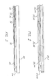
FIG. 1 a plan view of an exemplary embodiment of the medical device constructed in accordance with the principles of the present invention and designated generally assurgical clamp 10, Thesurgical clamp 10 includes a handle assembly having elongatedhandles lock mechanism 16, similar to a conventional surgical hemostat. The elongated handles 12, 14 are connected to one another by pivot or hinge 18, and continue distally in the form of a firstelongated jaw 20 and a secondelongated jaw 22. At least one of theelongated jaws elongated jaw 20 includes anablation tool 24 positioned on theinner surface 26 of the firstelongated jaw 20. - Referring to
FIGS. 2-3 , theablation tool 24 includes anablation segment 28 having a thermally-tiansmissive region 30, and defining a fluid path having at least onefluid inlet 32 and afluid outlet 34 through theablation tool 24 to theablation segment 28, wherein thefluid inlet 32 is in fluid communication with a cryogenic fluid source, Also, even though many materials and structures can be thermally conductive or thermally transmissive if chilled to a very low temperature and/or cold soaked, as used herein, a "thermally-transmissive region" is intended to broadly encompass any structure or region of theablation tool 24 that readily conducts heat. - For example, a metal structure exposed (directly or indirectly) to the cryogenic fluid path is considered a thermally-
transmissive region 30 even if an adjacent polymeric or latex portion also permits heat transfer, but to a much lesser extent than the metal. Thus, the thermally-transmissive region 30 can be viewed as a relative term to compare the heat transfer characteristics of different catheter regions or structures, regardless of the material. - Furthermore, while the thermally-
transmissive region 30 can include a single, continuous, and uninterrupted surface or structure, it can also include multiple, discrete, thermally-transmissive structures that collectively define a thermally-transmissive region that is elongate or linear. Depending on the ability of the cryogenic system, or portions thereof, to handle given thermal loads, the ablation of an elongate tissue path can be performed in a single or multiple cycle process without having to relocate the catheter one or more times or drag it across tissue. - In an exemplary embodiment, as shown in
FIG. 4 , theablation segment 28 includes one ormore orifices 34, where theorifices 34 define the thermally-transmissive region 30. Theorifices 34 enable the application of cryogenic fluid directly onto the tissue to be treated. - Additionally, the second
elongated jaw 22 can include anablation tool 42 positioned on the inner surface 44 of the secondelongated jaw 22. Theablation tool 42 includes an ablation segment 46 having a thermally-transmissive region 30, and defines a fluid path having at least one fluid inlet 48 and a fluid outlet 50 through theablation tool 42 to the ablation segment 46, wherein the fluid inlet 48 is in fluid communication with a cryogenic fluid source. - In an exemplary embodiment, as shown in
FIG. 5 , thehandles elongated jaw 20 and the secondelongated jaw 22. Furthermore, as shown inFIG. 6 , the firstelongated jaw 20 and the secondelongated jaw 22 include a curved portion. - Additionally, the first
elongated jaw 20 and the secondelongated jaw 22 are malleable, each have a shape-holding deformability, that is, they have rigidity such that the firstelongated jaw 20 and the secondelongated jaw 22 each retain a first shape until manipulated to a further shape with the application of moderate pressure, and until reshaped. The firstelongated jaw 20 and the secondelongated jaw 22 retain their shape with sufficient rigidity to manipulate theablation segment 28 against tissue, and push it past intervening tissue to a desired position - It is understood that shape, as used herein, is to be construed broadly to include any contour which is needed to configure the first
elongated jaw 20 and the secondelongated jaw 22 for positioning the active or distal portion of theablation tool 24, and may include successive bends or segments having more than one curve, angle, deformation or other non-linear configuration, The shape-retaining feature of the firstelongated jaw 20 and the secondelongated jaw 22 allows an operator to bend the firstelongated jaw 20 and the secondelongated jaw 22 to a shape or contour, for example around an organ or tissue structure, and have an optimal configuration for positioning and or orienting the active or distal region of the firstelongated jaw 20 and the secondelongated jaw 22 based upon the particular anatomy of a patient and the location of the treatment site. - Further, the stiffness of first
elongated jaw 20 and the secondelongated jaw 22 is such that the surgeon can form the firstelongate jaw 20 and the secondelongated jaw 22 by hand to a desired shape without undue effort, and yet the firstelongated jaw 20 and the secondelongated jaw 22 retain the set shape as thesurgical clamp 10 is maneuvered to and held in position at the treatment site. The firstelongated jaw 20 and the secondelongated jaw 22 should also be sufficiently rigid such that the surgeon can place theablation segment 28 of theablation tool 24 in pressured contact with the tissue treatment site. That is, the firstelongated jaw 20 and the secondelongated jaw 22 are sufficiently stiff to enable the surgeon to press theablation segment 28 against the tissue to be treated without inducing a further deformation in the shape of the firstelongated jaw 20 and the secondelongated jaw 22. The firstelongated jaw 20 and the secondelongated jaw 22 may in some embodiments deflect slightly, and yet have sufficient stiffness to transfer an effective level of lateral force at their distal end. - In an exemplary embodiment, the first
elongated jaw 20 and the secondelongated jaw 22 are configured so that they are deformable in a single plane, where the firstelongated jaw 20 and the secondelongated jaw 22 remain substantially rigid in all other planes, For example, the firstelongated jaw 20 and the secondelongated jaw 22 can be manipulated in a first plane "P1" from a first shape to a second shape, wherein the firstelongated jaw 20 and the secondelongated jaw 22 are sufficiently rigid to retain the second shape. The firstelongated jaw 20 and the secondelongated jaw 22 also have sufficient rigidity such that the firstelongated jaw 20 and the secondelongated jaw 22 cannot be manipulated in a second plane "P2" orthogonal to the first plane, such that the firstelongated jaw 20 and the secondelongated jaw 22 are deformable only in the first plane "P1." As such, the firstelongate jaw 20 and the secondelongated jaw 22 are deformable in only one plane. - In accordance with yet another aspect of the invention, as shown in
FIG. 7 , particularly directed to the ablative properties ofablation segments 28, 44, the energy distribution during treatment of tissue is further controlled by anadjustable insulation sleeve 52, wherein one each extends over and partially envelops theablation segments 28, 44. A slotted segment 54 in theinsulation sleeve 52 forms a partial circumferential blanket or insulating sleeve which prevents theablation segments 28,44 from affecting tissue on one side of theablation segments 28, 44, while leaving the other side of theablation segments 28, 44 exposed for contact with tissue. - In a further exemplary embodiment, as shown in
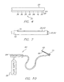
FIG. 8 , thesurgical clamp 10 includes a shaft assembly having afirst shaft 56 and asecond shaft 58 interposed between thehandles elongated jaw 20 and the secondelongated jaw 22. Thefirst shaft 56 and asecond shaft 58 operably connect the firstelongated jaw 20 and the secondelongated jaw 22 to thehandles elongated jaw 20 and the secondelongated jaw 22 are movable relative to one another from a first position, wherein the firstelongated jaw 22 and the secondelongated jaw 20 are disposed in a spaced apart relation relative to one another, to a second position, wherein the firstelongated jaw 20 and the secondelongated jaw 22 cooperate to grasp tissue therebetween. - Referring to
FIG. 9 , thefirst shaft 56 is substantially hollow, defining afirst lumen 60 having at least oneinput lumen 62 positioned therein, wherein thefirst lumen 60 and the at least onelumen 62 define a fluid path to theablation tool 24 on the firstelongated jaw 20. Thefirst lumen 60 and the at least onelumen 62 are in fluid communication with theablation fluid outlet 34 and theablation fluid inlet 32. - Additionally, similar to the
first shaft 56, thesecond shaft 58 can be substantially hollow, defining a first lumen having at least one input lumen positioned therein, wherein thefirst lumen 60 and the at least onelumen 62 define a fluid path to theablation tool 42 on the secondelongated jaw 22. The first lumen and the at least onelumen 62 are in fluid communication with the ablation fluid outlet 48 and the ablation fluid inlet 50. - The
first shaft 56 and thesecond shaft 58 are malleable, each have a shape-holding deformability, that is, they have a rigidity such that thefirst shaft 56 and thesecond shaft 58 each retain a first shape until manipulated to a further shape with the application of moderate pressure, and until reshaped. Thefirst shaft 56 and thesecond shaft 58 retain their shape with sufficient rigidity to close the firstelongated jaw 20 and the secondelongated jaw 22 to grasp the tissue, and push it past intervening tissue to a desired position. - It is understood that shape, as used herein, is to be construed broadly to include any contour which is needed to configure the
surgical clamp 10 for positioning the active or distal portion of theablation tool 24, and may include successive bends or segments having more than one curve, angle, deformation or other non-linear configuration. The shape-retaining feature of thefirst shaft 56 and thesecond shaft 58 allows an operator to bend thefirst shaft 56 and thesecond shaft 58 to a shape or contour, for example around an organ or tissue structure, and have an optimal configuration for positioning and or orienting the active or distal region of thesurgical clamp 10 based upon the particular anatomy of a patient and the location of the treatment site. - Further, the stiffness of the
first shaft 56 and thesecond shaft 58 is such that the surgeon can form thefirst shaft 56 and thesecond shaft 58 by hand to a desired shape without undue effort, and yet thefirst shaft 56 and thesecond shaft 58 retain the set shape as thesurgical clamp 10 is maneuvered to and held in position at the treatment site. Thefirst shaft 56 and thesecond shaft 58 should also be sufficiently rigid such that the surgeon can place theablation segment 28 of theablation tool 24 in pressured contact with the tissue treatment site. That is, thefirst shaft 56 and thesecond shaft 58 are sufficiently stiff to enable the surgeon to press theablation segment 28 against the tissue to be treated without inducing a further deformation in the shape of thefirst shaft 56 and thesecond shaft 58, Thefirst shaft 56 and thesecond shaft 58 may in some embodiments deflect slightly, and yet have sufficient stiffness to transfer an effective level of lateral force at their distal end. - In an embodiment, the
first shaft 56 and thesecond shaft 58 are configured so that they are deformable in a single plane, where thefirst shaft 56 and thesecond shaft 58 remain substantially rigid in all other planes. For example, thefirst shaft 56 and thesecond shaft 58 can be manipulated in a first plane "P1" from a first shape to a second shape, wherein the first shaft 48 and thesecond shaft 56 are sufficiently rigid to retain the second shape. Thefirst shaft 56 and thesecond shaft 58 also have sufficient rigidity such that thefirst shaft 56 and thesecond shaft 58 cannot be manipulated in a second plane "P2" orthogonal to the first plane, such that thefirst shaft 56 and thesecond shaft 58 are deformable only in the first plane "P1." As such thefirst shaft 56 and thesecond shaft 58 are deformable in only one plane. - In an exemplary embodiment, as shown in
FIG. 10 , the present invention includes anablation control system 64 Theablation control system 64 includes a supply of cryogenic or coolingfluid 66 in communication with thesurgical clamp 10. Afluid controller 68 is interposed or is in-line between thecryogenic fluid supply 66 and thesurgical clamp 10 for regulating the flow ofcryogenic fluid 66 into thesurgical clamp 10 in response to a controller command. Controller commands can include programmed instructions, sensor signals, and manual user input. For example, thefluid controller 68 can be programmed or configured to increase and decrease the pressure of the fluid by predetermined pressure increments over predetermined time intervals. - In another exemplary embodiment, the
fluid controller 68 can be responsive to input from a user input device to permit flow of thecryogenic fluid 66 into thesurgical clamp 10. As also shown inFIG. 1 , one ormore temperature sensors 40 in electrical communication with thefluid controller 68 can be provided to regulate or terminate the flow ofcryogenic fluid 66 into thesurgical clamp 10 when a predetermined temperature at a selected point or points on or within theablation segment 28 is/are obtained. For example atemperature sensor 40 can be placed at a point proximate theablation tool 24 distal end andother temperature sensors 40 can be placed at spaced intervals between theablation tool 24 distal end and another point that is between the distal end and the proximal end. - In another exemplary embodiment, one or more sensors 70, such as a ECG leads, in electrical communication with the controller can be provided to regulate or terminate the flow of
cryogenic fluid 66 into theablation tool 24 depending on the electrical activity in the tissue being treated. For example, the firstelongated jaw 20 and secondelongated jaw 22 may provide feedback that permits a user to gauge the completeness of the ablation. Specifically, a lesion blocks electrical signals because it is non-conductive scar tissue. The firstelongated jaw 20 and secondelongated jaw 22 can be used to measure the ability of the lesion to block an electrical signal. Referring toFIG. 1 , an electrode 70 is affixed one each to the distal ends of the firstelongated jaw 20 and secondelongated jaw 22. In an exemplary use, the electrodes 70 are used to verify electrical isolation of the lesion created by theablation tool 24. For example, the firstelongated jaw 20 and the secondelongated jaw 22 are opened to position an electrode 70 on each side of the lesion, An electrical signal is transmitted from one electrode, through the lesion, to the opposite electrode. The lesion is considered electrically isolated if the receiving electrode is electrically silent to the signal. - Alternatively, the electrical sensors can be replaced or supplemented with pressure sensors. The pressure sensors can be used to determine when the ablation segment is in physical contact with the tissue to be treated.
- The cryogenic fluid can be in a liquid or a gas state, or combination thereof. An extremely low temperature can be achieved within the medical device, and more particularly at the ablation segment by cooling the fluid to a predetermined temperature prior to its introduction into the medical device, by allowing a liquid state cryogenic fluid to boil or vaporize, or by allowing a gas state cryogenic fluid to expand. Exemplary liquids include chlorodifluoromethane, polydimethylsiloxane, ethyl alcohol, HFC's such as AZ-20 (a 50-50 mixture of difluoromethane & pentafluoroethane sold by Allied Signal), and CFC's such as DuPont's Freon. Exemplary gasses include argon, nitrous oxide, and carbon dioxide.
- Referring now to
FIG. 11 , there is shown a plan view of an exemplary embodiment of a medical device constructed in accordance with the principles of the present invention and designated generally assurgical clamp 100. Thesurgical clamp 100 includes a shaft assembly having opposingjaw assemblies jaw assembly 102 being fixed andjaw assembly 104 being movable between a first position, wherein thejaw assemblies jaw assemblies - The fixed
jaw assembly 102 includes a fixedextension shaft 106 and anablation tool 108 disposed on the distal end of the fixedextension shaft 106, at an acute angle to the fixedextension shaft 106. As shown inFIG. 12 , the fixedextension shaft 106 defines a first lumen 110 having at least one input lumen 112 positioned therein, wherein the first lumen 110 and the at least one input lumen 112 define a fluid path to theablation tool 108, wherein the at least one input lumen 112 is in fluid communication with a cryogenic fluid source. Theablation tool 108 includes an ablation segment 114 with a theimally-transraissive region 116, defines a fluid path through theablation tool 108 to the ablation segment 112, wherein the fluid path is in fluid communication with the first lumen 110 and the at least one input lumen 112, - The
moveable jaw assembly 104 includes amovable extension shaft 118 and amoveable jaw 120 disposed on the distal end of themoveable extension shaft 118 at an acute angle to themoveable extension shaft 118. Themoveable extension shaft 118 is operably connected to the fixedextension shaft 106, such that themoveable extension shaft 118 slides along the fixedextension shaft 106 to move themoveable jaw 120 between a first position, wherein themoveable jaw 120 and theablation tool 108 are disposed in a spaced apart relation relative to one another, to a second position, wherein themoveable jaw 120 and theablation tool 108 cooperate to grasp tissue therebetween. - In an exemplary embodiment, the
ablation tool 108 and themoveable jaw 120 are malleable, each having a shape-holding deformability, that is, they have rigidity such that theablation tool 108 and themoveable jaw 120 each retain a first shape until manipulated to a further shape with the application of moderate pressure, and until reshaped. Theablation tool 108 and themoveable jaw 120 retain their shape with sufficient rigidity to manipulate the ablation segment 114 against the tissue, and push it past intervening tissue to a desired position. - It is understood that shape, as used herein, is to be construed broadly to include any contour which is needed to configure the
ablation tool 108 and themoveable jaw 120 for positioning the active or distal portion of theablation tool 104, and may include successive bends or segments having more than one curve, angle, deformation or other non-linear configuration. The shape-retaining feature of theablation tool 108 and themoveable jaw 120 allows an operator to bend theablation tool 108 and themoveable jaw 120 to a shape or contour, for example around an organ or tissue structure, and have an optimal configuration for positioning and or orienting the active or distal region of theablation tool 108 and themoveable jaw 120 based upon the particular anatomy of a patient and the location of the treatment site. - Further, the stiffness of the
ablation tool 108 and themoveable jaw 120 is such that the surgeon can form theablation tool 108 and themoveable jaw 120 by hand to a desired shape without undue effort, and yet theablation tool 108 and themoveable jaw 120 retain the set shape as thesurgical clamp 100 is maneuvered to and held in position at the treatment site. Theablation tool 108 and the moveable j aw 120 should also be sufficiently rigid such that the surgeon can place theablation tool 108 and themoveable jaw 120 in pressured contact with the tissue treatment site. That is, theablation tool 108 and themoveable jaw 120 are sufficiently stiff to enable the surgeon to press the ablation segment 114 against the tissue to be treated without inducing a further deformation in the shape of theablation tool 108 and themoveable jaw 120. Theablation tool 108 and themoveable jaw 120 may in some embodiments deflect slightly, and yet has sufficient stiffness to transfer an effective level of lateral force at its distal end. - In an exemplary embodiment, the
ablation tool 108 and themoveable jaw 120 are configured so that they are deformable in a single plane, where theablation tool 108 and themoveable jaw 120 remain substantially rigid in all other planes. For example, theablation tool 108 and themoveable jaw 120 can be manipulated in a first plane "P1" from a first shape to a second shape, wherein theablation tool 108 and themoveable jaw 120 are sufficiently rigid to retain the second shape. Theablation tool 108 and themoveable jaw 120 also have sufficient rigidity such that theablation tool 108 and themoveable jaw 120 cannot be manipulated in a second plane "P2" orthogonal to the first plane, such that theablation tool 108 and themoveable jaw 120 are deformable only in the first plane "P1." As such theablation tool 108 and themoveable jaw 120 are deformable in only one plane. - In an exemplary embodiment, the fixed
extension shaft 106 and themoveable extension shaft 118 are malleable, each have a shape-holding deformability, that is, they have a rigidity such that the fixedextension shaft 106 and themoveable extension shaft 118 shaft each retain a first shape until manipulated to a further shape with the application of moderate pressure, and until reshaped. The fixedextension shaft 106 and themoveable extension shaft 118 retain their shape with sufficient rigidity to close theablation tool 108 and themoveable jaw 120 to grasp the tissue, and push it past intervening tissue to a desired position. The shape-retaining feature of the fixedextension shaft 106 and themoveable extension shaft 118 allows an operator to bend the fixedextension shaft 106 and themoveable extension shaft 118 to a shape or contour, for example around an organ or tissue structure, and have an optimal configuration for positioning and or orienting the active or distal region of thesurgical clamp 100 based upon the particular anatomy of a patient and the location of the treatment site. - It is understood that shape, as used herein, is to be construed broadly to include any contour which is needed to configure the fixed
extension shaft 106 and themoveable extension shaft 118 for positioning the active or distal portion of theablation tool 104, and may include successive bends or segments having more than one curve, angle, deformation or other non-linear configuration. The shape-retaining feature of the fixedextension shaft 106 and themoveable extension shaft 118 allows an operator to bend the fixedextension shaft 106 and themoveable extension shaft 118 to a shape or contour, for example around an organ or tissue structure, and have an optimal configuration for positioning and or orienting the active or distal region of the fixedextension shaft 106 and themoveable extension shaft 118 based upon the particular anatomy of a patient and the location of the treatment site. - Further, the stiffness of the fixed
extension shaft 106 and themoveable extension shaft 118 is such that the surgeon can form the fixedextension shaft 106 and themoveable extension shaft 118 by hand to a desired shape without undue effort, and yet the fixed extension shaft and the moveable extension shaft retains the set shape as thesurgical clamp 100 is maneuvered to and held in position at the treatment sit, The fixedextension shaft 106 and themoveable extension shaft 118 should also be sufficiently rigid such that the surgeon can place the ablation segment of the ablation segment 114 in pressured contact with the tissue treatment site. That is, the fixedextension shaft 106 and themoveable extension shaft 118 are sufficiently stiff to enable the surgeon to press the ablation segment 114 against the issue to be treated without inducing a further deformation in the shape of the fixedextension shaft 106 and themoveable extension shaft 118. The fixedextension shaft 106 and themoveable extension shaft 118 may in some embodiments deflect slightly, and yet haves sufficient stiffness to transfer an effective level of lateral force at its distal end. - In an embodiment, the fixed
extension shaft 106 and themoveable extension shaft 118 are configured so that they are deformable in a single plane, where the fixedextension shaft 106 and themoveable extension shaft 118 remain substantially frigid in all other planes. For example, the fixedextension shaft 106 and themoveable extension shaft 118 can be manipulated in a first plane "P1." from a first shape to a second shape, wherein the fixedextension shaft 106 and themoveable extension shaft 118 are sufficiently rigid to retain the second shape. The fixedextension shaft 106 and themoveable extension shaft 118 also have sufficient rigidity such that the fixedextension shaft 106 and the moveable extension shalt 118 cannot be manipulated in a second plane "P2" orthogonal to the first plane, such that the fixedextension shaft 106 and themoveable extension shaft 118 are deformable only in the first plane "P1." As such the fixedextension shaft 106 and themoveable extension shaft 118 are deformable in only one plane. - Referring to
FIG. 12 , themoveable extension shaft 118 defines a first lumen 122 having at least one input lumen 124 positioned therein, the first lumen 122 and the at least one input lumen 124 defining a fluid path to themoveable jaw 120, wherein the at least one fluid input lumen 124 is in fluid communication with a cryogenic fluid source. Themoveable jaw 120 is an ablation tool including an ablation segment 126 with a thermally-transmissive region 128, and defining a fluid path through themoveable jaw 120 to the ablation segment 126, wherein the fluid path is in fluid communication with the first lumen 122 and the at least one input lumen 124, - The fixed
jaw assembly 102 and themoveable jaw 104 assembly are operably connected to a handle assembly 103. The handle assembly 130 includes a fixed handle 132 attached to the fixedextension shaft 106 and a lever arm 134 pivotally connected to the fixed handle 132. The lever aim 134 is attached to the movable extension shaft, 118 such that as the lever arm 134 pivots about the fixed handle 132 from a start position, themoveable jaw 120 moves from a first position to a second position. - Referring now to
FIG. 13 , there is shown a plan view of an exemplary embodiment of a medical device constructed in accordance with the principles of the present invention and designated generally assurgical clamp 200. Thesurgical clamp 200 includes a jaw assembly having afirst jaw 202, and asecond jaw 204 in opposing relation. Thefirst jaw 202 and thesecond jaw 204 are movable between a first position, wherein thefirst jaw 202 and thesecond jaw 204 are disposed in a spaced apart relation relative to one another, to a second position, wherein thefirst jaw 202 and thesecond jaw 204 cooperate to grasp tissue therebetween., Thefirst jaw 202 and thesecond jaw 204 are connected to anelongated shaft assembly 206, wherein ahandle assembly 208 is connected to theelongated shaft assembly 206 opposite thefirst jaw 202 and thesecond jaw 204. At least one of thefirst jaw 202 and thesecond jaw 204 includes an ablation tool. For example, thefirst jaw 202 includes anablation tool 210 positioned on the inner surface 212 of thefirst jaw 202. - The
elongated shaft assembly 206 defines a first lumen 212 having at least oneinput lumen 214 positioned therein, The first lumen 212 and the at least oneinput lumen 214 define a fluid path to theablation tool 210, wherein the at least oneinput lumen 214 is in fluid communication with a cryogenic fluid source. The ablation tool 201 includes anablation segment 216 with a thermally-transmissive region 218, and defines a fluid path through the ablation, tool to theablation segment 218, wherein the fluid path is in fluid communication with the first lumen 212 and the at least oneinput lumen 214, - Additionally, the
second jaw 204 can include anablation tool 220 having anablation segment 222 with a thermally-transmissive region 224, and defining a fluid path through theablation tool 220 to theablation segment 222, wherein the fluid path is in fluid communication with the first lumen 212 and the at least oneinput lumen 214. - In an exemplary embodiment, the
first jaw 202 and thesecond jaw 204 are malleable, each have a shape-holding deformability, that is, they have rigidity such that thefirst jaw 202 and thesecond jaw 204 each retain a first shape until manipulated to a further shape with the application of moderate pressure, and until reshaped. Thefirst jaw 202 and thesecond jaw 204 retain their shape with sufficient rigidity to manipulate theablation segment 216 against tissue, and push it past intervening tissue to a desired position. - It is understood that shape, as used herein, is to be construed broadly to include any contour which is needed to configure the
first jaw 202 and thesecond jaw 204 for positioning the active or distal portion of the ablation tool, and may include successive bends or segments having more than one curve, angle, deformation or other non-linear configuration. The shape-retaining feature of thefirst jaw 202 and thesecond jaw 204 allows an operator to bend thefirst jaw 202 and thesecond jaw 204 to a shape or contour, for example around an organ or tissue structure, and have an optimal configuration for positioning and or orienting the active or distal region of thefirst jaw 202 and thesecond jaw 204 based upon the particular anatomy of a patient and the location of the treatment site, - Further, the stiffness of the
first jaw 202 and thesecond jaw 204 is such that the surgeon can form thefirst jaw 202 and thesecond jaw 204 by hand to a desired shape without undue effort, and yet thefirst jaw 202 and thesecond jaw 204 retain the set shape as thesurgical clamp 200 is maneuvered to and held in position at the treatment site, Thefirst jaw 202 and thesecond jaw 204 should also be sufficiently rigid such that the surgeon can place the ablation segment of the ablation tool in pressured contact with the tissue treatment site. That is, thefirst jaw 202 and thesecond jaw 204 are sufficiently stiff to enable the surgeon to press the ablation segment against the tissue to be treated without inducing a further deformation in the shape of thefirst jaw 202 and thesecond jaw 204. Thefirst jaw 202 and thesecond jaw 204 may in some embodiments deflect slightly, and yet have sufficient stiffness to transfer an effective level of lateral force at its distal end - In an exemplary embodiment, the
first jaw 202 and thesecond jaw 204 are configured so that they are deformable in a single plane, where thefirst jaw 202 and the second j aw 204 remain substantially rigid in all other planes. For example, thefirst jaw 202 and thesecond jaw 204 can be manipulated in a first plane "P1" from a first shape to a second shape, wherein thefirst jaw 202 and thesecond jaw 204 are sufficiently rigid to retain the second shape. Thefirst jaw 202 and thesecond jaw 204 also have sufficient rigidity such that the ffirst jaw 202 and thesecond jaw 204 cannot be manipulated in a second plane "P2" orthogonal to the first plane, such that thefirst jaw 202 and thesecond jaw 204 are deformable only in the first plane "P1." As such thefirst jaw 202 and thesecond jaw 204 are deformable in only one plane. - In an exemplary embodiment, the
elongated shaft assembly 206 is malleable, having a shape-holding deformability, that is, it has rigidity such that theelongated shaft assembly 206 retains a first shape until manipulated to a further shape with the application of moderate pressure, and until reshaped. Theelongated shaft assembly 206 retains its shape with sufficient rigidity to close thefirst jaw 202 and thesecond jaw 204 to grasp the tissue, and push it past intervening tissue to a desired position. - It is understood that shape, as used herein, is to be construed broadly to include any contour which is needed to configure the
surgical clamp 200 for positioning the active or distal portion of the ablation tool, and may include successive bends or segments having more than one curve, angle, deformation or other non-linear configuration. The shape-retaining feature of theelongated shaft assembly 206 allows an operator to bend theelongated shaft assembly 206 to a shape or contour, for example around an organ or tissue structure, and have an optimal configuration for positioning and or orienting the active or distal region of thesurgical clamp 200 based upon the particular anatomy of a patient and the location of the treatment site. - Further, the stiffness of the
elongated shaft assembly 206 is such that the surgeon can form theelongated shaft assembly 206 by hand to a desired shape without undue effort, and yet the elongatedshaft assembly 206 retains the set shape as thesurgical clamp 200 is maneuvered to and held in position at the treatment site, Theelongated shaft assembly 206 should also be sufficiently rigid such that the surgeon can place the ablation segment of the ablation tool in pressured contact with the tissue treatment site. That is, theelongate shaft assembly 206 is sufficiently stiff to enable the surgeon to press the ablation segment against the tissue to be treated without inducing a further deformation in the shape of theelongated shaft assembly 206. Theelongated shaft assembly 206 may in some embodiments deflect slightly, and yet has sufficient stiffness to transfer an effective level of lateral force at its distal end. - In an embodiment, the
elongated shaft assembly 206 is configured so that it is deformable in a single plane, where theelongated shaft assembly 206 remains substantially rigid in all other planes.. For example, theelongated shaft assembly 206 can be manipulated in a first plane "P1" from a first shape to a second shape, wherein theelongated shaft assembly 206 is sufficiently rigid to retain the second shape. Theelongated shaft assembly 206 also has sufficient rigidity such that theelongated shaft assembly 206 cannot be manipulated in a second plane "P2" orthogonal to the first plane, such that theelongated shaft assembly 206 is deformable only in the first plane "P1." As such theelongated shaft assembly 206 are deformable in only one plane. - Referring now to
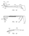
FIG. 14 , an exemplary tool is shown having ahandle portion 208 from which extends aprobe 210 having a cooling segment 212. As will all disclosed embodiments, the cooing segment 212 can be provided with a smooth or texturedtissue engaging surface 214. InFIG. 14 , the tissue-engagingsurface 214 is textures to have "teeth." Asecond element 216 is movable relative to the probe to define atissue capture zone 218. Adistal region 220 of thesecond element 216 can have a complementary shape to the cooling segment 212 and be smooth (as shown) or textured. As theprobe 210 and thesecond element 216 are moved axially with respect to each other, thetissue capture zone 218 increases or decreases in size. In the illustrated embodiment, thesecond element 216 is secured to theprobe 210 and is axially slidable with respect thereto by axially moving aproximal portion 222 of the second element. - With respect to
FIG. 15 , a different actuating mechanism is shown in an exemplary tool having ahandle portion 224 from which extends a probe 226 having acooling segment 228. Asecond element 230 is movable relative to the probe 226 to define atissue capture zone 232. As the probe 226 and thesecond element 230 are moved axially with respect to each other, thetissue capture zone 232 increases or decreases in size, In the illustrated embodiment, thesecond element 230 is secured to the probe 226 and is axially slidable with respect thereto by axially moving aproximal portion 234 of the second element by pulling a handle, lever, or trigger 236 that is engaged with the proximal portion of the second element. A spring 238 or other bias means can be provided to either urge thesecond element 230 in either the distal or proximal direction -
FIG. 16 shows yet another configuration wherein acooling element 240 is juxtaposed asecond element 242 and wherein the elements are biased apart. A sleeve or handle element is slidable with respect to the elements so that as it is moved distally it urges the elements together. - Referring to
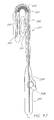
FIG. 17 another clamping tool is disclosed that includes ahandle portion 246 having an actuator 248 that pivots or rotates fore and aft. Theactuator 248 is coupled to a pull or pushwire 250 that is secured to a distal portion of anelongate shaft structure 252 to cause the shaft structure to clamptissue 254. As shown, theshaft structure 252 includes an insulatingdistal portion 256, a bellows orcoil portion 258 that provides a clamping effect, and acooling segment 260. Acoolant injection tube 262 introduces coolant into thecooling segment 260. Theelongate shaft structure 252 can be transitioned from a substantially linear configuration to the configuration shown or it can be preformed to substantially the configuration shown and actuated to tighten the space between the insulatingdistal portion 256 and thecooling segment 260 which can further be insulated on its outward face.. As shown, thewire 250 is secured at its distal end to ashim 264. -
FIG, 18 illustrates yet another configuration of a tool including ahandle 266,actuator 268,insulated shaft 270,first jaw 272, andsecond jaw 274, wherein manipulation of the actuator, 268 causes the jaws to open and close or move relative to each other. The figure depicts the jaws in both the open and clamped state. Coolant can flow to and/or through one or both jaws and both jaws can be insulated except at the point where they meet. One or both jaws can be provided with temperature and/or impedance measurement devices to monitor and evaluate lesion formation and characteristics. In an embodiment a temperature sensor is associated with a jaw that does not have a cooling element. The jaws are clamped together with tissue therebetween. The transmurality of a lesion could be ascertained when the temperature sensor detects a temperature of-40 degrees Centigrade for two minutes. Of course time and temperature may be different for different types, conditions and thickness of tissue. -
FIGS. 19 and 20 show additional details of thefirst jaw 272 and thesecond jaw 274, respectively; wherein the first jaw made of an insulating material defines arecess 276 shaped to receive anelongate cooling element 278 affixed to insulating material. - Although the device of
FIG. 18 may include two jaws, one jaw can be removable so that a single jaw with a cooling segment is provided, Thus, the device can be convertible from a clamping tool to a "wand" type device for use in procedures not requiring clamping. -
FIG. 21 illustrates yet another configuration for the clamping device. Here, coolingsegment 260 can be deflected from its normal position to a variety of deflection positions via use of actuator 248 (not shown).Cooling segment 260 may be deflected to an angle of choice my manipulation of the actuator. Coolant can then be introduced tocooling segment 260 via the internal injection tube (not shown). -
FIG. 22 illustrated yet another configuration for a clamping device wherein acooling element 280 is slidably disposed within an insulatingsheath 282. The distal portion of thecooling element 281 and the distal portion of thesheath 283 are angled with respect to their proximal portion so that extension and retraction of the cooling element with respect to the sheath opens and closes a tissue-clampingzone 284. - Although generally shown as a cryogenic ablation tool, it is understood that in other embodiments the ablation segment applies other types of energy or combination of energies, to the tissue to be treated, including, but not limited to, cryogenic energy, radio frequency (RF) energy, microwave energy, ultrasound energy, laser energy, and contact heating energy. It is further understood that other devices can be coupled to the guide distal end, for example, camera, video devices, probes and other components can be affixed to the guide for various applications For example, pacing/sensing electrodes can be affixed to points on ton the slotted segment.
- The medical device of the present invention is well suited for treating tissue in a variety of locations in the body during invasive surgical procedures. Illustrative applications include open thoracic and peritoneal surgery as well as endoscopic procedures, e.g., treating tissue located at or near the heart, intestines, uterus, and other regions for which surgical or endoscope assisted surgical access and topical tissue treatment, or cauterization or ablation is appropriate, as well as ophthalmic surgery, and tumor ablation and various applications preparatory to further surgical steps.
- FEATURES:
- 1. A medical device for ablating tissue comprising:
- a pair of opposing jaws positionable from a first position to a second position, at least one of the opposing jaws including an ablation element; and
- a shaft assembly operable connected to the opposing jaws, the shaft assembly having a malleability such that the shaft assembly retains a first shape until manipulated to a second shape.
- 2. The medical device according to feature 1, further comprising a handle assembly attached to the shaft assembly opposite the pair of opposing jaws, the handle assembly being operably connected to the pair of opposing jaws to move the pair of opposing jaws from the first position to the second position.
- 3. The medical device according to feature 1, further comprising an ablation control system operably connected to the at least one ablation element.
- 4. The medical device according to feature 3, further including at least one temperature sensor positioned on at least one of the opposing jaws and operably connected to the ablation control system.
- 5. The medical device according to feature 3, further including at least one signal electrode positioned on each of the opposing jaws and operably connected to the ablation control system.
- 6. The medical device according to feature 1, further comprising a moveable insulation sleeve configured to partially surround the at least one ablation element,
- 7. The medical device according to feature 1, wherein the pair of opposing jaws have a malleability such that the pair of opposing jaws retain a first shape until manipulated to a second shape.
- 8. The medical instrument according to feature 7, wherein the pair of opposing jaws are malleable within a first plane and are substantially rigid within a second plane orthogonal to the first plane.
- 9. The medical device according to feature 1, wherein the at least one ablation tool is configured to circulate cryogenic fluid therethrough for ablation of the tissue contacting the ablation element.
- 10. The medical device according to feature 9, wherein the at least one ablation element includes at least one orifice such that cryogenic fluid can be applied directly to the tissue.
- 11. The medical device according to feature 1, wherein the pair of opposing jaws comprise a first jaw and a second jaw, the first jaw including a first jaw ablation tool having at least one first jaw ablation segment.
- 12. The medical device according to feature 11, wherein the second jaw includes a second jaw ablation tool having at least one second jaw ablation segment,
- 13. The medical device according to feature 11, wherein the second jaws is removably attached to the shaft.
- 14. The medical device according to feature 11, wherein the shaft assembly comprises a first shaft attached to the first jaw and a second shaft attached to the second jaw.
- 15. The medical device according to
feature 14, wherein the first shaft and the second shaft are pivotally connected. - 16. The medical device according to
feature 14, wherein the first shaft and the second shaft are sliding connected. - 17. The medical device according to feature 1, wherein the shaft assembly is malleable within a first plane and is substantially rigid within a second plane orthogonal to the first plane.
- 18. The medical device according to feature 1, wherein the at least one ablation tool is configured to transfer ablation energy selected from the group consisting of cryogenic energy, radio frequency energy, microwave energy, ultrasound energy, laser energy, chemical energy, and contact heating energy.
- 19. A medical device for ablating tissue comprising:
- a first jaw and a second jaw, the fust jaw including a first jaw ablation tool having at least one first jaw ablation, segment;
- a shaft assembly operable connected to the first jaw and the second jaw, the shaft assembly having a malleability such that the shaft assembly retains a first shape until manipulated to a second shape; and
- a handle assembly attached to the shaft assembly opposite the first jaw and the second jaw, the handle assembly operably connected to the first jaw and the second jaw to move the first jaw and the second jaw from a first position to a second position.
- 20. The medical device according to feature 19, wherein the second jaw includes a second jaw ablation tool having at least one second jaw ablation segment.
- 21. The medical device according to
feature 20, wherein the second ablation tool is configured to circulate cryogenic fluid there through for ablation of the tissue contacting the second ablation tool. - 22. The medical device according to feature 19, wherein the second jaws is removably attached to the shaft.
- 23. The medical device according to feature 19, wherein the shaft assembly comprises a first shaft attached to the first jaw and a second shaft attached to the second jaw.
- 24. The medical device according to feature 23, wherein the first shaft and the second shaft are pivotally connected.
- 25. The medical device according to feature 23, wherein the first shaft and the second shaft are sliding connected.
- 26. The medical device according to feature 19, wherein the shaft assembly is malleable within a first plane and is substantially rigid within a second plane orthogonal to the first plane.
- 27. The medical device according to feature 19, further including at least one temperature sensor positioned on the first jaw.
- 28. The medical device according to feature 19, further including at least one signal electrode positioned on the first jaw and the second jaw.
- 29. The medical device according to feature 19, wherein the first ablation tool is configured to circulate cryogenic fluid therethrough for ablation of the tissue contacting the ablation tool.
- 30. The medical device according to feature 19, wherein the first jaw and the second jaws have a malleability such that the first jaw and the second jaw retain a first shape until manipulated to a second shape.
- 31. The medical instrument according to feature 30, wherein the first jaw and the second jaw are malleable within a first plane and are substantially rigid within a second plane orthogonal to the first plane.
- 32. A medical device for ablating tissue comprising:
- a first jaw and a second jaw, the first jaw including a first jaw ablation tool configured to circulate cryogenic fluid there through and having at least one first jaw ablation segment;
- a shaft assembly operable connected to the first jaw and the second jaw, the shaft assembly having a malleability such that the shaft assembly retains a first shape until manipulated to a second shape;
- a handle assembly attached to the shaft assembly opposite the first jaw and the second jaw, the handle assembly operably connected to the first jaw and the second,jaw to move the first jaw and the second jaw from a first position to a second position; and
- an ablation control system operably connected to the first ablation tool.
- 33. The medical device according to
feature 32, wherein the second jaw includes a secondjaw ablation tool configured to circulate cryogenic fluid there through and having at least one second jaw ablation segment, the second ablation tool being operably connected to the ablation control system. - 34. The medical device according to feature 33, wherein the second jaw is removably attached to the shaft.
- 35. The medical device according to
feature 32, wherein the shaft assembly comprises a first shaft attached to the first jaw and a second shaft attached to the second jaw. - 36. The medical device according to feature 35, wherein the first shaft and the second shaft are pivotally connected.
- 37. The medical device according to feature 35, wherein the first shaft and the second shaft are sliding connected.
- 38. The medical device according to
feature 32, wherein the shaft assembly is malleable within a first plane and is substantially rigid within a second plane orthogonal to the first plane. - 39. The medical device according to
feature 32, further including at least one signal electrode positioned on the first jaw and the second jaw. - 40. A medical device comprising an elongate shaft, a cooling element, and a second element movable with respect to the cooling element to define a clamp, wherein the movable element is selectively detachable from the shaft
- It will be appreciated by persons skilled in the art that the present invention is not limited to what has been particularly shown and described hereinabove In addition, unless mention was made above to the contrary, it should be noted that all of the accompanying drawings are not to scale A variety of modifications and variations are possible in light of the above teachings without departing from the scope and spirit of the invention, which is limited only by the following claims
Claims (5)
- A medical device for ablating tissue comprising an elongate shaft structure defining an insulating portion (256);a handle (246) connected to the insulating portion (256) of the shaft structure;a bellows portion (258) having a first end and a second end;a cooling segment (260); anda coolant injection tube (262) for introducing coolant into the cooling segment (260);wherein the first end of the bellows portion (258) is connected to the insulating portion (256), and the second end of the bellows portion (258) is connected to the cooling segment (260) so that the insulating portion (256) and the cooling segment (260) can be laterally juxtaposed, substantially parallel to each other.
- A device as claimed in Claim 1 further comprising:an actuation assembly (248) operably coupled to the shaft structure to move the cooling segment (260) from a first position to a second position to create a tissue clamping region.
- A device as claimed in Claim 4 wherein the actuation assembly (248) comprises:a deflection mechanism; and,a linkage assembly (250) operatively coupled to the deflection mechanism;wherein activation of the deflection mechanism displaces the cooling segment (260) in a substantially parallel orientation to the insulating portion (256) to create the tissue clamping region.
- A device as claimed in Claim 2 wherein the linkage assembly (250) is a pull wire (250).
- A device as claimed in Claim 2 wherein the cooling segment (260) has additional insulation on an outward face.
Applications Claiming Priority (3)
| Application Number | Priority Date | Filing Date | Title |
|---|---|---|---|
| US10/458,745 US7044946B2 (en) | 2003-06-10 | 2003-06-10 | Surgical clamp having treatment elements |
| EP04822190A EP1706053A2 (en) | 2003-06-10 | 2004-06-10 | Surgical clamp having treatment elements |
| US10/890,364 US7347856B2 (en) | 2003-06-10 | 2004-07-13 | Minimally invasive surgical clamp having treatment elements |
Related Parent Applications (1)
| Application Number | Title | Priority Date | Filing Date |
|---|---|---|---|
| EP04822190.7 Division | 2004-06-10 |
Publications (2)
| Publication Number | Publication Date |
|---|---|
| EP2189126A1 true EP2189126A1 (en) | 2010-05-26 |
| EP2189126B1 EP2189126B1 (en) | 2011-08-24 |
Family
ID=35783482
Family Applications (3)
| Application Number | Title | Priority Date | Filing Date |
|---|---|---|---|
| EP04822190A Withdrawn EP1706053A2 (en) | 2003-06-10 | 2004-06-10 | Surgical clamp having treatment elements |
| EP10151596A Active EP2189126B1 (en) | 2003-06-10 | 2004-06-10 | Surgical clamp having treatment elements |
| EP05768217A Not-in-force EP1781190B1 (en) | 2003-06-10 | 2005-07-13 | Minimally invasive surgical clamp having treatment elements |
Family Applications Before (1)
| Application Number | Title | Priority Date | Filing Date |
|---|---|---|---|
| EP04822190A Withdrawn EP1706053A2 (en) | 2003-06-10 | 2004-06-10 | Surgical clamp having treatment elements |
Family Applications After (1)
| Application Number | Title | Priority Date | Filing Date |
|---|---|---|---|
| EP05768217A Not-in-force EP1781190B1 (en) | 2003-06-10 | 2005-07-13 | Minimally invasive surgical clamp having treatment elements |
Country Status (5)
| Country | Link |
|---|---|
| US (2) | US7044946B2 (en) |
| EP (3) | EP1706053A2 (en) |
| AT (1) | ATE521294T1 (en) |
| CA (2) | CA2536201C (en) |
| WO (2) | WO2006032951A2 (en) |
Cited By (1)
| Publication number | Priority date | Publication date | Assignee | Title |
|---|---|---|---|---|
| EP4140424A1 (en) * | 2021-08-31 | 2023-03-01 | Medinice S.A. | A cryoprobe for minimally invasive cardiac ablation with a functional tip |
Families Citing this family (56)
| Publication number | Priority date | Publication date | Assignee | Title |
|---|---|---|---|---|
| US6161543A (en) * | 1993-02-22 | 2000-12-19 | Epicor, Inc. | Methods of epicardial ablation for creating a lesion around the pulmonary veins |
| US7582083B2 (en) * | 2004-05-10 | 2009-09-01 | Boston Scientific Scimed, Inc. | Probe based low temperature lesion formation apparatus, systems and methods |
| US7288088B2 (en) * | 2004-05-10 | 2007-10-30 | Boston Scientific Scimed, Inc. | Clamp based low temperature lesion formation apparatus, systems and methods |
| WO2005120376A2 (en) * | 2004-06-02 | 2005-12-22 | Medtronic, Inc. | Ablation device with jaws |
| EP1799130A1 (en) * | 2004-09-14 | 2007-06-27 | Uromedica, Inc. | Implantation tool for adjustable implantable genitourinary device |
| WO2009120953A2 (en) | 2008-03-27 | 2009-10-01 | Mayo Foundation For Medical Education And Research | Navigation and tissue capture systems and methods |
| US20100081915A1 (en) * | 2008-09-29 | 2010-04-01 | Searete Llc, Alimited Liability Corporation Of The State Of Delaware | Histological facilitation systems and methods |
| US10695126B2 (en) | 2008-10-06 | 2020-06-30 | Santa Anna Tech Llc | Catheter with a double balloon structure to generate and apply a heated ablative zone to tissue |
| US8444642B2 (en) * | 2009-04-03 | 2013-05-21 | Device Evolutions, Llc | Laparoscopic nephrectomy device |
| US20100331838A1 (en) * | 2009-06-25 | 2010-12-30 | Estech, Inc. (Endoscopic Technologies, Inc.) | Transmurality clamp systems and methods |
| US9198683B2 (en) | 2009-09-30 | 2015-12-01 | Aegis Medical Innovations, Inc. | Tissue capture and occlusion systems and methods |
| US9144431B2 (en) * | 2009-09-30 | 2015-09-29 | Aegis Medical Innovations Inc. | Enhanced signal navigation and capture systems and methods |
| EA025508B1 (en) | 2010-02-05 | 2016-12-30 | ТАВАЙДЕРМ ЭлЭлСи | Method and device for the treatment of skin lesions |
| US20110208174A1 (en) * | 2010-02-23 | 2011-08-25 | Cpsi Biotech | Cryoclamp and method of use |
| US9936996B2 (en) * | 2010-03-30 | 2018-04-10 | Medtronic ATS Medical, Inc. | Cryoprobe having internal warming fluid capabilities |
| US8523930B2 (en) | 2010-05-14 | 2013-09-03 | Neuraxis, Llc | Methods and devices for cooling spinal tissue |
| US9498278B2 (en) | 2010-09-08 | 2016-11-22 | Covidien Lp | Asymmetrical electrodes for bipolar vessel sealing |
| US8685021B2 (en) * | 2010-11-17 | 2014-04-01 | Covidien Lp | Method and apparatus for vascular tissue sealing with active cooling of jaws at the end of the sealing cycle |
| US9265568B2 (en) | 2011-05-16 | 2016-02-23 | Coviden Lp | Destruction of vessel walls for energy-based vessel sealing enhancement |
| US20130289562A1 (en) * | 2012-04-27 | 2013-10-31 | Medtronic, Inc. | Bi-Polar Ablation Devices and Methods of Use |
| US9861802B2 (en) | 2012-08-09 | 2018-01-09 | University Of Iowa Research Foundation | Catheters, catheter systems, and methods for puncturing through a tissue structure |
| US8721642B1 (en) * | 2013-01-28 | 2014-05-13 | Neuraxis, Llc | Tissue cooling clamps and related methods |
| US9439717B2 (en) | 2013-08-13 | 2016-09-13 | Covidien Lp | Surgical forceps including thermal spread control |
| US9308123B2 (en) | 2013-09-16 | 2016-04-12 | Neuraxis, Llc | Methods and devices for applying localized thermal therapy |
| US8911486B1 (en) | 2013-09-16 | 2014-12-16 | Neuraxis, Llc | Implantable devices for thermal therapy and related methods |
| EP3091921B1 (en) | 2014-01-06 | 2019-06-19 | Farapulse, Inc. | Apparatus for renal denervation ablation |
| EP4238521A3 (en) | 2014-05-07 | 2023-11-29 | Farapulse, Inc. | Methods and apparatus for selective tissue ablation |
| EP3154463B1 (en) | 2014-06-12 | 2019-03-27 | Farapulse, Inc. | Apparatus for rapid and selective transurethral tissue ablation |
| WO2015192018A1 (en) * | 2014-06-12 | 2015-12-17 | Iowa Approach Inc. | Method and apparatus for rapid and selective tissue ablation with cooling |
| EP3206613B1 (en) | 2014-10-14 | 2019-07-03 | Farapulse, Inc. | Apparatus for rapid and safe pulmonary vein cardiac ablation |
| WO2016086028A1 (en) * | 2014-11-24 | 2016-06-02 | The Board Of Regents Of The University Of Oklahoma | Surgical cleaning tool, system, and method |
| US10226269B2 (en) * | 2015-05-27 | 2019-03-12 | Covidien Lp | Surgical forceps |
| CN107106234B (en) * | 2015-07-16 | 2020-03-27 | 奥林巴斯株式会社 | Treatment tool |
| US10130423B1 (en) | 2017-07-06 | 2018-11-20 | Farapulse, Inc. | Systems, devices, and methods for focal ablation |
| US10172673B2 (en) | 2016-01-05 | 2019-01-08 | Farapulse, Inc. | Systems devices, and methods for delivery of pulsed electric field ablative energy to endocardial tissue |
| US20170189097A1 (en) | 2016-01-05 | 2017-07-06 | Iowa Approach Inc. | Systems, apparatuses and methods for delivery of ablative energy to tissue |
| US10660702B2 (en) | 2016-01-05 | 2020-05-26 | Farapulse, Inc. | Systems, devices, and methods for focal ablation |
| US11331140B2 (en) | 2016-05-19 | 2022-05-17 | Aqua Heart, Inc. | Heated vapor ablation systems and methods for treating cardiac conditions |
| EP3471631A4 (en) | 2016-06-16 | 2020-03-04 | Farapulse, Inc. | Systems, apparatuses, and methods for guide wire delivery |
| US9987081B1 (en) | 2017-04-27 | 2018-06-05 | Iowa Approach, Inc. | Systems, devices, and methods for signal generation |
| US10617867B2 (en) | 2017-04-28 | 2020-04-14 | Farapulse, Inc. | Systems, devices, and methods for delivery of pulsed electric field ablative energy to esophageal tissue |
| EP3681391A1 (en) | 2017-09-12 | 2020-07-22 | Farapulse, Inc. | Systems, apparatuses, and methods for ventricular focal ablation |
| US10932781B2 (en) * | 2018-02-06 | 2021-03-02 | Ethicon Llc | Features to align and close linear surgical stapler |
| CN108403179B (en) * | 2018-03-19 | 2019-11-05 | 重庆良护科技有限公司 | Haemostatic clamp is used in operation |
| CN112087978B (en) | 2018-05-07 | 2023-01-17 | 波士顿科学医学有限公司 | Epicardial ablation catheter |
| CN112118798A (en) | 2018-05-07 | 2020-12-22 | 法拉普尔赛股份有限公司 | Systems, devices, and methods for filtering high voltage noise induced by pulsed electric field ablation |
| CN112087980B (en) | 2018-05-07 | 2023-01-10 | 波士顿科学医学有限公司 | Systems, devices, and methods for delivering ablation energy to tissue |
| WO2020061359A1 (en) | 2018-09-20 | 2020-03-26 | Farapulse, Inc. | Systems, apparatuses, and methods for delivery of pulsed electric field ablative energy to endocardial tissue |
| CN109171950B (en) * | 2018-09-25 | 2020-12-29 | 高传玉 | Remove renal artery sympathetic nerve radio frequency ablation pincers for art |
| AU2019380263A1 (en) | 2018-11-15 | 2021-05-20 | Applied Medical Resources Corporation | Laparoscopic grasper with force-limiting grasping mechanism |
| US11103267B2 (en) * | 2018-12-18 | 2021-08-31 | American University Of Beirut | Surgical forceps and methods of use |
| US10625080B1 (en) | 2019-09-17 | 2020-04-21 | Farapulse, Inc. | Systems, apparatuses, and methods for detecting ectopic electrocardiogram signals during pulsed electric field ablation |
| US11497541B2 (en) | 2019-11-20 | 2022-11-15 | Boston Scientific Scimed, Inc. | Systems, apparatuses, and methods for protecting electronic components from high power noise induced by high voltage pulses |
| US11065047B2 (en) | 2019-11-20 | 2021-07-20 | Farapulse, Inc. | Systems, apparatuses, and methods for protecting electronic components from high power noise induced by high voltage pulses |
| US10842572B1 (en) | 2019-11-25 | 2020-11-24 | Farapulse, Inc. | Methods, systems, and apparatuses for tracking ablation devices and generating lesion lines |
| CN113288401B (en) * | 2021-05-26 | 2021-11-30 | 海杰亚(北京)医疗器械有限公司 | Surgical device |
Citations (3)
| Publication number | Priority date | Publication date | Assignee | Title |
|---|---|---|---|---|
| WO2001082810A1 (en) | 2000-04-27 | 2001-11-08 | Cryocath Technologies, Inc. | Catheter |
| US6319248B1 (en) | 1998-07-29 | 2001-11-20 | Cryocath Technologies, Inc. | Spray catheter |
| US20020177845A1 (en) | 2001-05-25 | 2002-11-28 | Heiner Peter Wilfred | Cryoablation catheter with an improved gas expansion chamber |
Family Cites Families (51)
| Publication number | Priority date | Publication date | Assignee | Title |
|---|---|---|---|---|
| US565122A (en) * | 1896-08-04 | Platform-scale | ||
| DE3544483A1 (en) | 1985-12-16 | 1987-06-19 | Peter Dipl Ing Feucht | NEUTRAL ELECTRODE AND CONNECTING TERMINAL FOR THIS |
| DE3729516A1 (en) | 1987-07-13 | 1989-03-16 | Siemens Ag | MULTI-PIECE ELECTRODE AND CONNECTING CLAMP THEREFOR |
| US4867404A (en) | 1988-05-16 | 1989-09-19 | The United States Of America As Represented By The Department Of Health And Human Services | Flexible holder for a cystoscope or the like |
| EP0369324B1 (en) | 1988-11-11 | 1995-11-02 | United States Surgical Corporation | Surgical instrument |
| US5304183A (en) | 1992-03-23 | 1994-04-19 | Laparomed Corporation | Tethered clamp retractor |
| US6161543A (en) | 1993-02-22 | 2000-12-19 | Epicor, Inc. | Methods of epicardial ablation for creating a lesion around the pulmonary veins |
| US5496312A (en) | 1993-10-07 | 1996-03-05 | Valleylab Inc. | Impedance and temperature generator control |
| US5536267A (en) | 1993-11-08 | 1996-07-16 | Zomed International | Multiple electrode ablation apparatus |
| GB2283678B (en) * | 1993-11-09 | 1998-06-03 | Spembly Medical Ltd | Cryosurgical catheter probe |
| US5452513A (en) | 1994-06-29 | 1995-09-26 | Eric Hulsman | Suture cutter |
| US6142994A (en) * | 1994-10-07 | 2000-11-07 | Ep Technologies, Inc. | Surgical method and apparatus for positioning a diagnostic a therapeutic element within the body |
| US6152920A (en) | 1997-10-10 | 2000-11-28 | Ep Technologies, Inc. | Surgical method and apparatus for positioning a diagnostic or therapeutic element within the body |
| US6690963B2 (en) * | 1995-01-24 | 2004-02-10 | Biosense, Inc. | System for determining the location and orientation of an invasive medical instrument |
| US5776130A (en) | 1995-09-19 | 1998-07-07 | Valleylab, Inc. | Vascular tissue sealing pressure control |
| US5733280A (en) | 1995-11-15 | 1998-03-31 | Avitall; Boaz | Cryogenic epicardial mapping and ablation |
| US5762069A (en) | 1995-12-29 | 1998-06-09 | Akos Biomedical, Inc. | Multiple sample biopsy forceps |
| US5904711A (en) | 1996-02-08 | 1999-05-18 | Heartport, Inc. | Expandable thoracoscopic defibrillation catheter system and method |
| US6036667A (en) | 1996-10-04 | 2000-03-14 | United States Surgical Corporation | Ultrasonic dissection and coagulation system |
| US6237605B1 (en) | 1996-10-22 | 2001-05-29 | Epicor, Inc. | Methods of epicardial ablation |
| US6071303A (en) | 1996-12-08 | 2000-06-06 | Hearten Medical, Inc. | Device for the treatment of infarcted tissue and method of treating infarcted tissue |
| US6102909A (en) * | 1997-08-26 | 2000-08-15 | Ethicon, Inc. | Scissorlike electrosurgical cutting instrument |
| US6024744A (en) | 1997-08-27 | 2000-02-15 | Ethicon, Inc. | Combined bipolar scissor and grasper |
| US6139563A (en) | 1997-09-25 | 2000-10-31 | Allegiance Corporation | Surgical device with malleable shaft |
| US6352536B1 (en) | 2000-02-11 | 2002-03-05 | Sherwood Services Ag | Bipolar electrosurgical instrument for sealing vessels |
| US6050996A (en) * | 1997-11-12 | 2000-04-18 | Sherwood Services Ag | Bipolar electrosurgical instrument with replaceable electrodes |
| US6187003B1 (en) | 1997-11-12 | 2001-02-13 | Sherwood Services Ag | Bipolar electrosurgical instrument for sealing vessels |
| US6527767B2 (en) | 1998-05-20 | 2003-03-04 | New England Medical Center | Cardiac ablation system and method for treatment of cardiac arrhythmias and transmyocardial revascularization |
| US6241722B1 (en) * | 1998-06-17 | 2001-06-05 | Cryogen, Inc. | Cryogenic device, system and method of using same |
| US6174309B1 (en) | 1999-02-11 | 2001-01-16 | Medical Scientific, Inc. | Seal & cut electrosurgical instrument |
| US6217528B1 (en) | 1999-02-11 | 2001-04-17 | Scimed Life Systems, Inc. | Loop structure having improved tissue contact capability |
| US6440126B1 (en) * | 1999-04-21 | 2002-08-27 | Cryocath Technologies | Cryoblation catheter handle |
| US6270476B1 (en) * | 1999-04-23 | 2001-08-07 | Cryocath Technologies, Inc. | Catheter |
| US6558385B1 (en) * | 2000-09-22 | 2003-05-06 | Tissuelink Medical, Inc. | Fluid-assisted medical device |
| AU2001250047A1 (en) * | 2000-03-24 | 2001-10-08 | Baylor College Of Medicine | Effector-specific protein assembly and uses thereof |
| US6926712B2 (en) * | 2000-03-24 | 2005-08-09 | Boston Scientific Scimed, Inc. | Clamp having at least one malleable clamp member and surgical method employing the same |
| US6546935B2 (en) | 2000-04-27 | 2003-04-15 | Atricure, Inc. | Method for transmural ablation |
| US20020107514A1 (en) * | 2000-04-27 | 2002-08-08 | Hooven Michael D. | Transmural ablation device with parallel jaws |
| US6932811B2 (en) * | 2000-04-27 | 2005-08-23 | Atricure, Inc. | Transmural ablation device with integral EKG sensor |
| US6544477B1 (en) | 2000-08-01 | 2003-04-08 | Regents Of The University Of Minnesota | Apparatus for generating a temperature gradient |
| US6740085B2 (en) | 2000-11-16 | 2004-05-25 | Olympus Corporation | Heating treatment system |
| JP4202138B2 (en) | 2001-01-31 | 2008-12-24 | レックス メディカル インコーポレイテッド | Apparatus and method for stapling and ablating gastroesophageal tissue |
| US6775575B2 (en) * | 2001-02-26 | 2004-08-10 | D. Bommi Bommannan | System and method for reducing post-surgical complications |
| US7101371B2 (en) | 2001-04-06 | 2006-09-05 | Dycus Sean T | Vessel sealer and divider |
| US6648883B2 (en) | 2001-04-26 | 2003-11-18 | Medtronic, Inc. | Ablation system and method of use |
| US6544274B2 (en) | 2001-05-02 | 2003-04-08 | Novare Surgical Systems, Inc. | Clamp having bendable shaft |
| DE10129754A1 (en) * | 2001-06-20 | 2003-01-02 | Holger Jungmann | Detection of the presence of substances in vital tissue materials by passing light of a given wavelength through the material for its intensity to be compared with a reference system |
| US6849075B2 (en) * | 2001-12-04 | 2005-02-01 | Estech, Inc. | Cardiac ablation devices and methods |
| AU2003224486A1 (en) * | 2002-05-02 | 2003-11-17 | Doosan Corporation | Composition for treating cancer containing n,n-dimethylphytosphingosine |
| US7291161B2 (en) | 2002-10-02 | 2007-11-06 | Atricure, Inc. | Articulated clamping member |
| US7083620B2 (en) * | 2002-10-30 | 2006-08-01 | Medtronic, Inc. | Electrosurgical hemostat |
-
2003
- 2003-06-10 US US10/458,745 patent/US7044946B2/en not_active Expired - Lifetime
-
2004
- 2004-06-10 EP EP04822190A patent/EP1706053A2/en not_active Withdrawn
- 2004-06-10 WO PCT/IB2004/004470 patent/WO2006032951A2/en active Search and Examination
- 2004-06-10 AT AT10151596T patent/ATE521294T1/en not_active IP Right Cessation
- 2004-06-10 EP EP10151596A patent/EP2189126B1/en active Active
- 2004-06-10 CA CA2536201A patent/CA2536201C/en active Active
- 2004-07-13 US US10/890,364 patent/US7347856B2/en not_active Expired - Fee Related
-
2005
- 2005-07-13 WO PCT/CA2005/001095 patent/WO2006005188A1/en not_active Application Discontinuation
- 2005-07-13 EP EP05768217A patent/EP1781190B1/en not_active Not-in-force
- 2005-07-13 CA CA002573181A patent/CA2573181C/en not_active Expired - Fee Related
Patent Citations (3)
| Publication number | Priority date | Publication date | Assignee | Title |
|---|---|---|---|---|
| US6319248B1 (en) | 1998-07-29 | 2001-11-20 | Cryocath Technologies, Inc. | Spray catheter |
| WO2001082810A1 (en) | 2000-04-27 | 2001-11-08 | Cryocath Technologies, Inc. | Catheter |
| US20020177845A1 (en) | 2001-05-25 | 2002-11-28 | Heiner Peter Wilfred | Cryoablation catheter with an improved gas expansion chamber |
Cited By (1)
| Publication number | Priority date | Publication date | Assignee | Title |
|---|---|---|---|---|
| EP4140424A1 (en) * | 2021-08-31 | 2023-03-01 | Medinice S.A. | A cryoprobe for minimally invasive cardiac ablation with a functional tip |
Also Published As
| Publication number | Publication date |
|---|---|
| EP2189126B1 (en) | 2011-08-24 |
| EP1781190B1 (en) | 2013-04-03 |
| CA2536201C (en) | 2012-12-11 |
| WO2006032951A2 (en) | 2006-03-30 |
| US7044946B2 (en) | 2006-05-16 |
| WO2006032951A8 (en) | 2006-07-13 |
| ATE521294T1 (en) | 2011-09-15 |
| EP1781190A4 (en) | 2010-02-10 |
| WO2006032951A3 (en) | 2006-08-10 |
| US20040254607A1 (en) | 2004-12-16 |
| CA2573181C (en) | 2010-01-19 |
| CA2536201A1 (en) | 2004-12-10 |
| US20050043729A1 (en) | 2005-02-24 |
| EP1781190A1 (en) | 2007-05-09 |
| EP1706053A2 (en) | 2006-10-04 |
| CA2573181A1 (en) | 2006-01-19 |
| US7347856B2 (en) | 2008-03-25 |
| WO2006005188A1 (en) | 2006-01-19 |
Similar Documents
| Publication | Publication Date | Title |
|---|---|---|
| CA2536201C (en) | Surgical clamp having treatment elements | |
| EP1755464B1 (en) | Surgical clamp having trasmurality assessment capabilities | |
| US20130165927A1 (en) | Surgical clamp having treatment elements | |
| US20190105104A1 (en) | Cardiac treatment devices and methods | |
| US6849075B2 (en) | Cardiac ablation devices and methods | |
| US6913604B2 (en) | Cryosurgical catheter | |
| US20040199154A1 (en) | Device for tissue ablation | |
| US8764745B2 (en) | Cryoprobe clamp having transmurality assessment window | |
| EP1467668B1 (en) | Cryosurgical catheter | |
| US11344355B2 (en) | Cardiac surgery cryoprobe |
Legal Events
| Date | Code | Title | Description |
|---|---|---|---|
| PUAI | Public reference made under article 153(3) epc to a published international application that has entered the european phase |
Free format text: ORIGINAL CODE: 0009012 |
|
| AC | Divisional application: reference to earlier application |
Ref document number: 1706053 Country of ref document: EP Kind code of ref document: P |
|
| AK | Designated contracting states |
Kind code of ref document: A1 Designated state(s): AT BE BG CH CY CZ DE DK EE ES FI FR GB GR HU IE IT LI LU MC NL PL PT RO SE SI SK TR |
|
| RAP1 | Party data changed (applicant data changed or rights of an application transferred) |
Owner name: MEDTRONIC CRYOCATH LP |
|
| 17P | Request for examination filed |
Effective date: 20101115 |
|
| GRAP | Despatch of communication of intention to grant a patent |
Free format text: ORIGINAL CODE: EPIDOSNIGR1 |
|
| RIC1 | Information provided on ipc code assigned before grant |
Ipc: A61B 18/02 20060101AFI20110301BHEP |
|
| GRAS | Grant fee paid |
Free format text: ORIGINAL CODE: EPIDOSNIGR3 |
|
| GRAA | (expected) grant |
Free format text: ORIGINAL CODE: 0009210 |
|
| AC | Divisional application: reference to earlier application |
Ref document number: 1706053 Country of ref document: EP Kind code of ref document: P |
|
| AK | Designated contracting states |
Kind code of ref document: B1 Designated state(s): AT BE BG CH CY CZ DE DK EE ES FI FR GB GR HU IE IT LI LU MC NL PL PT RO SE SI SK TR |
|
| REG | Reference to a national code |
Ref country code: GB Ref legal event code: FG4D |
|
| REG | Reference to a national code |
Ref country code: CH Ref legal event code: EP |
|
| REG | Reference to a national code |
Ref country code: IE Ref legal event code: FG4D |
|
| REG | Reference to a national code |
Ref country code: DE Ref legal event code: R096 Ref document number: 602004034167 Country of ref document: DE Effective date: 20111117 |
|
| REG | Reference to a national code |
Ref country code: NL Ref legal event code: VDEP Effective date: 20110824 |
|
| PG25 | Lapsed in a contracting state [announced via postgrant information from national office to epo] |
Ref country code: PT Free format text: LAPSE BECAUSE OF FAILURE TO SUBMIT A TRANSLATION OF THE DESCRIPTION OR TO PAY THE FEE WITHIN THE PRESCRIBED TIME-LIMIT Effective date: 20111226 Ref country code: NL Free format text: LAPSE BECAUSE OF FAILURE TO SUBMIT A TRANSLATION OF THE DESCRIPTION OR TO PAY THE FEE WITHIN THE PRESCRIBED TIME-LIMIT Effective date: 20110824 Ref country code: SE Free format text: LAPSE BECAUSE OF FAILURE TO SUBMIT A TRANSLATION OF THE DESCRIPTION OR TO PAY THE FEE WITHIN THE PRESCRIBED TIME-LIMIT Effective date: 20110824 Ref country code: FI Free format text: LAPSE BECAUSE OF FAILURE TO SUBMIT A TRANSLATION OF THE DESCRIPTION OR TO PAY THE FEE WITHIN THE PRESCRIBED TIME-LIMIT Effective date: 20110824 |
|
| REG | Reference to a national code |
Ref country code: AT Ref legal event code: MK05 Ref document number: 521294 Country of ref document: AT Kind code of ref document: T Effective date: 20110824 |
|
| PG25 | Lapsed in a contracting state [announced via postgrant information from national office to epo] |
Ref country code: AT Free format text: LAPSE BECAUSE OF FAILURE TO SUBMIT A TRANSLATION OF THE DESCRIPTION OR TO PAY THE FEE WITHIN THE PRESCRIBED TIME-LIMIT Effective date: 20110824 Ref country code: SI Free format text: LAPSE BECAUSE OF FAILURE TO SUBMIT A TRANSLATION OF THE DESCRIPTION OR TO PAY THE FEE WITHIN THE PRESCRIBED TIME-LIMIT Effective date: 20110824 Ref country code: PL Free format text: LAPSE BECAUSE OF FAILURE TO SUBMIT A TRANSLATION OF THE DESCRIPTION OR TO PAY THE FEE WITHIN THE PRESCRIBED TIME-LIMIT Effective date: 20110824 Ref country code: CY Free format text: LAPSE BECAUSE OF FAILURE TO SUBMIT A TRANSLATION OF THE DESCRIPTION OR TO PAY THE FEE WITHIN THE PRESCRIBED TIME-LIMIT Effective date: 20110824 Ref country code: GR Free format text: LAPSE BECAUSE OF FAILURE TO SUBMIT A TRANSLATION OF THE DESCRIPTION OR TO PAY THE FEE WITHIN THE PRESCRIBED TIME-LIMIT Effective date: 20111125 |
|
| PG25 | Lapsed in a contracting state [announced via postgrant information from national office to epo] |
Ref country code: BE Free format text: LAPSE BECAUSE OF FAILURE TO SUBMIT A TRANSLATION OF THE DESCRIPTION OR TO PAY THE FEE WITHIN THE PRESCRIBED TIME-LIMIT Effective date: 20110824 |
|
| PG25 | Lapsed in a contracting state [announced via postgrant information from national office to epo] |
Ref country code: SK Free format text: LAPSE BECAUSE OF FAILURE TO SUBMIT A TRANSLATION OF THE DESCRIPTION OR TO PAY THE FEE WITHIN THE PRESCRIBED TIME-LIMIT Effective date: 20110824 Ref country code: CZ Free format text: LAPSE BECAUSE OF FAILURE TO SUBMIT A TRANSLATION OF THE DESCRIPTION OR TO PAY THE FEE WITHIN THE PRESCRIBED TIME-LIMIT Effective date: 20110824 |
|
| PG25 | Lapsed in a contracting state [announced via postgrant information from national office to epo] |
Ref country code: EE Free format text: LAPSE BECAUSE OF FAILURE TO SUBMIT A TRANSLATION OF THE DESCRIPTION OR TO PAY THE FEE WITHIN THE PRESCRIBED TIME-LIMIT Effective date: 20110824 Ref country code: RO Free format text: LAPSE BECAUSE OF FAILURE TO SUBMIT A TRANSLATION OF THE DESCRIPTION OR TO PAY THE FEE WITHIN THE PRESCRIBED TIME-LIMIT Effective date: 20110824 Ref country code: IT Free format text: LAPSE BECAUSE OF FAILURE TO SUBMIT A TRANSLATION OF THE DESCRIPTION OR TO PAY THE FEE WITHIN THE PRESCRIBED TIME-LIMIT Effective date: 20110824 |
|
| PG25 | Lapsed in a contracting state [announced via postgrant information from national office to epo] |
Ref country code: DK Free format text: LAPSE BECAUSE OF FAILURE TO SUBMIT A TRANSLATION OF THE DESCRIPTION OR TO PAY THE FEE WITHIN THE PRESCRIBED TIME-LIMIT Effective date: 20110824 |
|
| PLBE | No opposition filed within time limit |
Free format text: ORIGINAL CODE: 0009261 |
|
| STAA | Information on the status of an ep patent application or granted ep patent |
Free format text: STATUS: NO OPPOSITION FILED WITHIN TIME LIMIT |
|
| 26N | No opposition filed |
Effective date: 20120525 |
|
| REG | Reference to a national code |
Ref country code: DE Ref legal event code: R097 Ref document number: 602004034167 Country of ref document: DE Effective date: 20120525 |
|
| PG25 | Lapsed in a contracting state [announced via postgrant information from national office to epo] |
Ref country code: MC Free format text: LAPSE BECAUSE OF NON-PAYMENT OF DUE FEES Effective date: 20120630 |
|
| REG | Reference to a national code |
Ref country code: CH Ref legal event code: PL |
|
| REG | Reference to a national code |
Ref country code: CH Ref legal event code: PL |
|
| GBPC | Gb: european patent ceased through non-payment of renewal fee |
Effective date: 20120610 |
|
| REG | Reference to a national code |
Ref country code: IE Ref legal event code: MM4A |
|
| PG25 | Lapsed in a contracting state [announced via postgrant information from national office to epo] |
Ref country code: ES Free format text: LAPSE BECAUSE OF FAILURE TO SUBMIT A TRANSLATION OF THE DESCRIPTION OR TO PAY THE FEE WITHIN THE PRESCRIBED TIME-LIMIT Effective date: 20111205 Ref country code: GB Free format text: LAPSE BECAUSE OF NON-PAYMENT OF DUE FEES Effective date: 20120610 Ref country code: IE Free format text: LAPSE BECAUSE OF NON-PAYMENT OF DUE FEES Effective date: 20120610 Ref country code: CH Free format text: LAPSE BECAUSE OF NON-PAYMENT OF DUE FEES Effective date: 20120630 Ref country code: LI Free format text: LAPSE BECAUSE OF NON-PAYMENT OF DUE FEES Effective date: 20120630 |
|
| PG25 | Lapsed in a contracting state [announced via postgrant information from national office to epo] |
Ref country code: BG Free format text: LAPSE BECAUSE OF FAILURE TO SUBMIT A TRANSLATION OF THE DESCRIPTION OR TO PAY THE FEE WITHIN THE PRESCRIBED TIME-LIMIT Effective date: 20111124 |
|
| PG25 | Lapsed in a contracting state [announced via postgrant information from national office to epo] |
Ref country code: TR Free format text: LAPSE BECAUSE OF FAILURE TO SUBMIT A TRANSLATION OF THE DESCRIPTION OR TO PAY THE FEE WITHIN THE PRESCRIBED TIME-LIMIT Effective date: 20110824 |
|
| PG25 | Lapsed in a contracting state [announced via postgrant information from national office to epo] |
Ref country code: LU Free format text: LAPSE BECAUSE OF NON-PAYMENT OF DUE FEES Effective date: 20120610 |
|
| PG25 | Lapsed in a contracting state [announced via postgrant information from national office to epo] |
Ref country code: HU Free format text: LAPSE BECAUSE OF FAILURE TO SUBMIT A TRANSLATION OF THE DESCRIPTION OR TO PAY THE FEE WITHIN THE PRESCRIBED TIME-LIMIT Effective date: 20040610 |
|
| REG | Reference to a national code |
Ref country code: FR Ref legal event code: PLFP Year of fee payment: 13 |
|
| REG | Reference to a national code |
Ref country code: FR Ref legal event code: PLFP Year of fee payment: 14 |
|
| REG | Reference to a national code |
Ref country code: FR Ref legal event code: PLFP Year of fee payment: 15 |
|
| REG | Reference to a national code |
Ref country code: DE Ref legal event code: R082 Ref document number: 602004034167 Country of ref document: DE Representative=s name: ZWICKER SCHNAPPAUF & PARTNER PATENTANWAELTE PA, DE |
|
| PGFP | Annual fee paid to national office [announced via postgrant information from national office to epo] |
Ref country code: FR Payment date: 20230523 Year of fee payment: 20 Ref country code: DE Payment date: 20230523 Year of fee payment: 20 |