EP2198683A1 - System for the automatic distribution of particles for an agricultural machine, and the corresponding module and method - Google Patents
System for the automatic distribution of particles for an agricultural machine, and the corresponding module and method Download PDFInfo
- Publication number
- EP2198683A1 EP2198683A1 EP09178557A EP09178557A EP2198683A1 EP 2198683 A1 EP2198683 A1 EP 2198683A1 EP 09178557 A EP09178557 A EP 09178557A EP 09178557 A EP09178557 A EP 09178557A EP 2198683 A1 EP2198683 A1 EP 2198683A1
- Authority
- EP
- European Patent Office
- Prior art keywords
- opening
- closing
- control signals
- actuators
- guide bar
- Prior art date
- Legal status (The legal status is an assumption and is not a legal conclusion. Google has not performed a legal analysis and makes no representation as to the accuracy of the status listed.)
- Granted
Links
- 239000002245 particle Substances 0.000 title claims abstract description 77
- 238000009826 distribution Methods 0.000 title claims abstract description 48
- 238000000034 method Methods 0.000 title claims abstract description 17
- 238000006243 chemical reaction Methods 0.000 claims abstract description 14
- 238000003892 spreading Methods 0.000 claims description 44
- 239000007921 spray Substances 0.000 claims description 19
- 238000005507 spraying Methods 0.000 claims description 13
- 238000005520 cutting process Methods 0.000 claims description 8
- 230000004913 activation Effects 0.000 claims description 3
- 230000008859 change Effects 0.000 claims description 3
- 238000001514 detection method Methods 0.000 claims description 3
- 238000007726 management method Methods 0.000 claims 4
- 230000007480 spreading Effects 0.000 description 43
- 239000003337 fertilizer Substances 0.000 description 18
- 230000001276 controlling effect Effects 0.000 description 16
- 239000007787 solid Substances 0.000 description 7
- 239000000047 product Substances 0.000 description 6
- 230000006978 adaptation Effects 0.000 description 3
- 238000010276 construction Methods 0.000 description 3
- 230000004048 modification Effects 0.000 description 3
- 238000012986 modification Methods 0.000 description 3
- 238000012545 processing Methods 0.000 description 3
- 241000238876 Acari Species 0.000 description 2
- IJGRMHOSHXDMSA-UHFFFAOYSA-N Atomic nitrogen Chemical compound N#N IJGRMHOSHXDMSA-UHFFFAOYSA-N 0.000 description 2
- 238000013459 approach Methods 0.000 description 2
- 238000010586 diagram Methods 0.000 description 2
- 201000010099 disease Diseases 0.000 description 2
- 208000037265 diseases, disorders, signs and symptoms Diseases 0.000 description 2
- 230000000694 effects Effects 0.000 description 2
- 230000000750 progressive effect Effects 0.000 description 2
- 230000035484 reaction time Effects 0.000 description 2
- 230000009467 reduction Effects 0.000 description 2
- 150000003839 salts Chemical class 0.000 description 2
- 238000009331 sowing Methods 0.000 description 2
- 238000009966 trimming Methods 0.000 description 2
- 238000005303 weighing Methods 0.000 description 2
- 241000221785 Erysiphales Species 0.000 description 1
- 244000098338 Triticum aestivum Species 0.000 description 1
- 230000000903 blocking effect Effects 0.000 description 1
- 235000013339 cereals Nutrition 0.000 description 1
- 230000008878 coupling Effects 0.000 description 1
- 238000010168 coupling process Methods 0.000 description 1
- 238000005859 coupling reaction Methods 0.000 description 1
- 230000007547 defect Effects 0.000 description 1
- 238000011161 development Methods 0.000 description 1
- 238000006073 displacement reaction Methods 0.000 description 1
- 230000007613 environmental effect Effects 0.000 description 1
- 239000012263 liquid product Substances 0.000 description 1
- 238000004519 manufacturing process Methods 0.000 description 1
- 239000000463 material Substances 0.000 description 1
- 230000007246 mechanism Effects 0.000 description 1
- 229910052757 nitrogen Inorganic materials 0.000 description 1
- 238000005457 optimization Methods 0.000 description 1
- 210000000056 organ Anatomy 0.000 description 1
- 235000012830 plain croissants Nutrition 0.000 description 1
- 230000001737 promoting effect Effects 0.000 description 1
- 238000011084 recovery Methods 0.000 description 1
- 230000001105 regulatory effect Effects 0.000 description 1
- 238000003860 storage Methods 0.000 description 1
Images


Classifications
-
- A—HUMAN NECESSITIES
- A01—AGRICULTURE; FORESTRY; ANIMAL HUSBANDRY; HUNTING; TRAPPING; FISHING
- A01C—PLANTING; SOWING; FERTILISING
- A01C17/00—Fertilisers or seeders with centrifugal wheels
- A01C17/006—Regulating or dosing devices
-
- A—HUMAN NECESSITIES
- A01—AGRICULTURE; FORESTRY; ANIMAL HUSBANDRY; HUNTING; TRAPPING; FISHING
- A01B—SOIL WORKING IN AGRICULTURE OR FORESTRY; PARTS, DETAILS, OR ACCESSORIES OF AGRICULTURAL MACHINES OR IMPLEMENTS, IN GENERAL
- A01B79/00—Methods for working soil
- A01B79/005—Precision agriculture
-
- A—HUMAN NECESSITIES
- A01—AGRICULTURE; FORESTRY; ANIMAL HUSBANDRY; HUNTING; TRAPPING; FISHING
- A01C—PLANTING; SOWING; FERTILISING
- A01C17/00—Fertilisers or seeders with centrifugal wheels
- A01C17/006—Regulating or dosing devices
- A01C17/008—Devices controlling the quantity or the distribution pattern
-
- A—HUMAN NECESSITIES
- A01—AGRICULTURE; FORESTRY; ANIMAL HUSBANDRY; HUNTING; TRAPPING; FISHING
- A01C—PLANTING; SOWING; FERTILISING
- A01C21/00—Methods of fertilising, sowing or planting
- A01C21/005—Following a specific plan, e.g. pattern
Definitions
- the field of the invention is that of the distribution of particles for agriculture, that is to say products in a granular form, including solid fertilizer or seeds.
- the invention relates to the control of the particle distribution provided by an agricultural machine, and in particular the optimization of the distribution in the areas near the border, a tip or the end of a field to be treated .
- FIG. 1 An example of a machine for spreading solid fertilizer or sowing on a crop plot is schematically illustrated on the figure 1 . It is in the form of a tractor 10 equipped with a hopper 11 containing fertilizer or seeds 14 to be spread.
- the bottom of the hopper 11 comprises two openings, then two adjustable feeding devices, then two fertilizer distribution adjusting devices, for example in the form of chutes 13 (only one being shown), allowing particles contained 14 in the hopper 11, and placed in overhang of two distributors each comprising a rotating disk 15 carrying projection blades.
- the discs 15 are most often arranged in a substantially horizontal position and their rotation about a substantially vertical axis 16 ensures the projection of the content 14 of the hopper by centrifugal effect, in the form of a sheet, in the general shape of a crescent , extending at the back of the spreading machine.
- the two rotating discs rotate in opposite directions with respect to each other, which makes it possible to spread fertilizer and / or seedling over a large width, typically between 5 and 50 meters.
- Such spreading machines make it possible to treat a parcel of arable land, or field, most often following a predefined path of return / return on it but also with non-imposed trajectories (for example for spreading on meadow).
- the operator of the machine can adapt certain spreading settings, such as, depending on the case, the quantity or weight of particles distributed, the shape of the spreading sheet, and in particular its width, ... It can moreover selectively opening or closing the feed device 13, so as to optimize the amounts of particles spread, especially at the headland, edge, end or field peak.
- overdose is not only expensive, but also harmful.
- overdose of N on soft wheat promotes lodging, reduces nitrogen efficiency by promoting its early storage in unproductive organs, and promotes the early development of diseases such as dumped mites or mites. powdery mildew. This is also in contradiction with the environmental requirements.
- the invention therefore aims to overcome these disadvantages of the prior art.
- an object of the invention is to propose a technique that makes it possible, simply and inexpensively, to improve, that is to say, optimize, the spreading of particles, such as solid fertilizers. or seeds, particularly at the edges, at the ends and at the ends of the field
- the invention aims, according to the embodiments, is to allow the implementation of a reasoned agriculture, reducing and optimizing the use of fertilizers, reducing the risk and some diseases, ...
- the invention also aims to improve the working comfort of the driver, and increase its safety and efficiency, including allowing him to focus on driving.
- Another object of the invention is to provide a technique that can be implemented with materials of different origins, and does not require heavy or specific mechanical or computer means.
- an object of the invention is to allow the use of conventional distributors, whose trays are driven by the PTO of the tractor.
- an agricultural machine particle distribution system comprising at least two particle distributors each equipped with at least a feed device whose opening and closing are controlled by a first actuator, cooperating with a spray management assembly, controlling sprayers and comprising a guide bar fed by geolocation means and cut-off means , receiving control signals of the opening and / or closing of said sections.
- the invention eliminates the implementation of a dedicated, heavy and expensive system for automating the spreading of particles. Indeed, few adaptations are necessary on most distributors, who are already equipped with hatches. Similarly, the invention exploits information provided by a guide bar (this term may include, in the claims, the guide bar itself and the associated section cutting means) conventional, and it is accordingly not necessary to provide geolocation means and specific processing means.
- the invention is therefore based on the adaptation and conversion of signals, originally intended for a spray boom, and produced by a guide bar, into commands for actuators dedicated to particle distribution means, such as a spreader.
- the characteristics of an area covered by a sprayer are very different from the shape of a particle spreading sheet and its distance from the tractor.
- Specific parameterization information available for example in the form of charts detailing the spreader-specific values to be set in the guidance bar (for example: forward / backward / right / left distance, reaction time, recovery rate ).
- the invention proposes to "lure" the guide bar, in order to control a particle distributor using commands in principle dedicated to a sprayer.
- system of the invention also comprises means for manually controlling the opening and closing of said feed devices.
- the driver can then act on the distribution manually, if necessary, independently of commands issued by the system.
- each power device can be open (maximum opening) or closed (total closure).
- said system comprising a device for adjusting the width of the distribution, said autonomous module is able to deliver a total or partial opening command and a total or partial closure command, and can control actuators secondary devices acting on said distribution width adjustment devices.
- the system may comprise means for selectively connecting a bundle of cables coming from said guide bar on the one hand to means for controlling said sprayers, and on the other hand to said autopilot module.
- said conversion means associates with a control signal opening or closing sections a control command of a quantity of particles to be supplied to each distributor.
- the position of the chute can make it possible to move the spreading zone, with respect to the tractor, and / or to modify its surface.
- said particles may in particular belong to the group comprising solid fertilizers, seedlings, slug products, salt, gravel.
- the particle distribution system may comprise, or cooperate with, weighing means of said particles, a speed sensor, ...
- system may comprise, or cooperate with, means for selectively implementing a clipping blade on each of said distributors, configured to change the shape of the spread sheet.
- the invention also relates to the autonomous modules for automatically controlling the particle distribution used in an agricultural machine particle distribution system comprising at least two particle distributors each equipped with at least one feed device of which the opening and closing are controlled by a first actuator.
- This module controls the opening and closing of said supply devices as a function of control signals delivered by an assembly comprising a guide bar supplied by geolocation means and means for cutting off sections, and intended to control sprayers. and comprising means for converting said control signals into opening and closing commands of said first actuators.
- this method also comprises a preliminary step of adjusting said guide bar, in which the parameters normally intended for the control of sprayers are adapted to a particle spreading sheet or to a distribution sheet of a seed drill, for example example a grain drill.
- the method comprises a step of controlling the opening of said dispensing devices, so that it can take at least one intermediate opening position, and / or the position of a chute , so as to modify an average ejection angle according to said control signals.
- the invention is based in particular on the use of a guide bar (this term may include, in the claims, the guide bar itself and the associated section cutting means) for controlling a sprayer , to a particle spreading system (especially solid fertilizer or sowing).
- a guide bar this term may include, in the claims, the guide bar itself and the associated section cutting means
- a particle spreading system especially solid fertilizer or sowing.
- the cuts of sections for sprayer are well known, for more than 20 years, and the solution of the invention can adapt to all the guide bars currently marketed with its section cuts.
- the Figure 2A illustrates, schematically, a tractor 21 equipped with a spray boom 22, comprising a plurality of sections 23, each making it possible to cover a substantially triangular surface 24, so that the overall covered surface is substantially homogeneous and of substantially rectangular shape .
- the tractor 21 is therefore equipped with cut-off means of the spray boom sections 23, which are increasingly common on farms.
- An example of such automatic control means is the "Accuboom" (registered trademark) system.
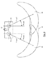
- the invention thus proposes a simple and effective solution for reusing and adapting these automatic piloting means to the spreading of particles, as illustrated by FIG. Figure 2B .
- the tractor 21 no longer carries a spray boom 22, but means for dispensing particles 25, for example granulated fertilizers or seedlings. It is equipped with two distributors supplying two discs 26 1 and 26 2 , which project the particles respectively onto surfaces 27 1 and 27 2 , together defining a cover surface 27, 5 to 20 m away from the distribution means 25 , and defining a general crescent shape.
- the information provided by the guide bar is used by means of controlling the sections of the spray boom, after having firstly adapted the parameterization and, secondly, transformed the signals, way they can control actuators, such as electric cylinders for example.
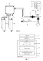
- conventional equipment for the control of a spray boom comprises geolocation means 31, generally in the form of an antenna placed on the tractor and a GPS module.
- a guide bar 32 which delivers information, depending on the geolocation, to means 33 for cutting sections of the spray boom ("Accuboom" for example).
- a module 35 for controlling the opening and closing of the feed devices by example traps, providing the supply of particles of disks 26 1 and 26 2 .
- This module 35 may include in particular double relays, allowing the actuation of electric cylinders 36 1 and 36 2 .
- These cylinders 36 1 and 36 2 are preferably fast cylinders, allowing almost instantaneous opening and closing of the hatches, so that the beginning or the interruption of the spreading is also almost instantaneous. If necessary, it is possible to set a reaction time of the actuators, to anticipate the opening or closing.
- the electronic means 35 furthermore comprise end-of-stroke detection means for the actuators, or more generally actuators, (to interrupt their supply when they have reached the end of the opening or closing stroke) and means for detection of anomaly or failure in its cylinders.
- a manual control box 37 may be provided, so as to allow the user to force the implementation of the actuators 36 1 and 36 2 , and therefore the opening or closing of the corresponding hatches, if necessary, and independently of the commands generated by the means 33 for controlling the spray bars.
- the guide bar 32 can be connected directly to an adjustment and control module 43 (for example of the "Vision” type (registered trademark) distributed by the holder of the present patent application), which can itself be powered by different sensors, and in particular by a speed sensor 44 (speed information which can advantageously be delivered directly by the guide bar), a weighing sensor ...
- an adjustment and control module 43 for example of the "Vision” type (registered trademark) distributed by the holder of the present patent application
- a speed sensor 44 speed information which can advantageously be delivered directly by the guide bar
- a weighing sensor ...
- This housing 43 is connected to second actuators 48 1 and 48 2 , via an electrical harness 47.
- These second actuators 48 1 and 48 2 make it possible to manage the flow rate as a function of the speed of advance and / or Hopper weight ... These are low speed, high precision actuators, while the module 35 acts on the first actuators 36 1 and 36 2 , faster.
- the piloting of the first actuators from the control information of the sections is not trivial. Indeed, the number of sections (typically 6, 8, 10 or more) is distinct from the number of first actuators (one per disk, or two), and the resulting layers are very different.
- the housing 43 may control, via additional actuators 48 3 , 48 4 , the setting of the feed point associated with each disk, so as to modify the shape of the web, and therefore its width, in relation to the information received by the cutoff means 33. It is also possible to control the speed and / or inclination of the disk, for example, to modify the position of the web relative to tractor.
- the housing 43 may, in a particular embodiment, control, by means of an additional actuator 48, the implementation of a clipping blade associated with at least one of the disks, so as to modify the shape of the spreading sheet, especially at the edge of the field.
- a clipping blade is known as "Tribord” (registered trademark), distributed by the holder of the present patent application.
- the figure 5 illustrates, in more detail, the new elements of the invention, in the embodiment of the figure 3 . More specifically, the figure 5 illustrates the dotted framed part of the figure 3 .
- connection means 51 to the cutoff means 33 sections (and / or the draw bar 32, according to the embodiments).
- connection means 51 may be variable, depending on the different manufacturers of guide bar.
- the means for implementing the invention may be designed to have various connectors or adapters, so that all the elements of the figure 5 can be implemented independently of the origin of the guide bar.
- the system includes, of course, means 52 for connection to a power supply, for example 12 volts corresponding to the battery of the tractor.
- LEDs can be associated with the three buttons to indicate the status of the actuators, and be lit to signal an alarm, in case of problems.
- This manual control box 54 is connected via a connector 55 to the electronic module 56.
- This module 56 has two outputs 57 1 , 57 2 , driving the cylinders 36 1 , 36 2 , through double relays.
- the module 56 is therefore adapted to transform the received signals into relay commands, to take into account the manual controls, and to ensure safety, notably by managing the limit switches of the cylinders (and by interrupting the power supplies of the cylinders at the end of the race). and detecting potential problems, such as inadvertent blocking of a cylinder.
- the Figures 6A and 6B schematically illustrate a mechanism for opening the hatches controlled by a jack, according to one embodiment of the invention. More specifically, the Figure 6A has a hatch 61 for feeding one of the disks, in the closed position. In this position, the hatch 61 closes the supply of one of the disks.
- the actuator 36 acts, by its end 361, on the hatch 61, mounted to rotate about an axis 65, to control the closing of the supply.
- Springs may be provided, to assist the movement of the hatch and / or maintain it in a desired position.
- a spring (not shown) returns the hatch to the open position when the end 61 of the jack is raised.
- the Figure 6B illustrates the system of fig 6A in the open position. In this position, the cylinder 36 is in a folded position, and it is found that the end 361 is raised, having simultaneously released the hatch 61, which has pivoted about the axis 65, to release the feed opening.
- the particles can then flow from the dispenser to the disc.
- the figure 7 presents in a simplified way a block diagram of the method of implementation of the invention.
- the guide bar is programmed, so as to take into account the particular settings of the spreading of particles, and in particular the position and shape of the sheet (see FIG. Figure 2B ).
- this adjustment step we will introduce information to take into account the width of the spreading sheet, or spreading width, the distance between the position of the GPS antenna and the heart of the sheet generated by each disk, and optionally a desired percentage of coverage, especially in the field tip.
- the number of sections is also regulated, for example by setting it to two (in the case of an all-or-nothing operation).
- the distance between the position of the GPS antenna and the core of the sheet generated by each disk may, for example, be between 5 and 20 meters towards the rear of the tractor, and between 3 and 15 meters on the side, for take into account the centrifugal projection of the device.
- the distance between the coupling of the distributor and the core of each sheet may be an average value, variable according to the working width and the type of blade used. This information can therefore be specified, for example also in charts.
- the spreading (more generally the distribution, according to the type of particles) 73, is implemented with the system of the invention.
- the module of the invention receives (731) the control signals delivered by the guide bar and the section cutoff means, converts (732) these signals, to control (733) the opening and closing of dispensing devices (and more generally, if necessary, the degree of opening and possibly other settings).
- the flow trap closes automatically ( Figure 6A ) when the coverage of the layers reaches the limit threshold initially programmed.
- the solution of the invention therefore makes it possible to equip a series distributor, with or without particular electronics, whose discs or trays are driven by the PTO of the tractor by means of conventional angle references. It exploits the information of the guide bars available on the market.
- a system automating the cuts and reopening of the flow rate during inputs of granular fertilizer or seedling, grafting on equipment potentially already present on a tractor, including the bar guide, the GPS antenna and the section management system.
- the invention makes it possible to improve the productivity of the work, and to optimize optimally the input (fertilizer for example) source of diffuse pollution, and expensive product.
- the invention also makes it possible to homogenize the productivity of a plot.
- the invention has in particular been described for application to the spreading of a solid fertilizer. It is clear however that it can be applied to the distribution of other types of particles, for example seedlings, slug products, salt, gravel.
- a drill it can actuate a cylinder closing half of the drill, reduce the dose of 50% in the tips, and / or cut the electric motor in the field ends.
- the guide bar controls 6 spraying sections, and thus delivers 6 separate control signals (binary) opening or closing.
- these 6 control signals will be converted in order to control the discs of a spreader, in particular the means which make it possible to control their feed, and in particular the shape of the spreading sheet, and the quantity of particles to spread.
- the autonomous module converts the 6 opening signals into maximum opening signals of the two hatches, and the spreading zone 81 is obtained in the form of increasing.
- this chute that adjusts the spreading width.
- This chute transfers the particles from the outlet of the metering orifice to the blades of the disk concerned, which will accelerate them to distribute them on the ground.
- the variation of the position of deposit of the product in the blades displaces the crescent spread on the ground (angular displacement)
- the shape of the spreading sheet thus has a general crescent shape (and not a rectangular shape as is the case for spraying), corresponding to the combination of two croissants generated by each of the disks, and whose respective surfaces are controlled by the adjustment of the chute, for example according to angular parameters ⁇ moyG and ⁇ moyD , corresponding to an average angle of ejection of the fertilizer with respect to the axis of advance 91.
- a stop distribution command (complete closure of the particle supply) is generated, as well as, if appropriate, a stop command of the right disk.
- a fast closing control of the door, intended for the actuator 36 2 may also be issued.
- the conversion performed by the autonomous module can be as follows: Control signals of the guide bar Dose of the left disc ⁇ moyG Cylinder 36 1 Dose of the right disk ⁇ moyD Cylinder 36 2 111111 100% 30 ° WE 100% -30 ° WE 111110 100% 30 ° WE 66% -25 ° WE 111100 100% 30 ° WE 33% -21 ° WE 111000 100% 30 ° WE 0% -30 ° OFF 110000 66% 35 ° WE 0% -30 ° OFF 100000 33% 42 ° WE 0% -30 ° OFF 000000 0% 30 ° OFF 0% -30 ° OFF 000001 0% 30 ° OFF 33% -42 ° WE 000011 0% 30 ° OFF 66% -35 ° WE 000111 0% 30 ° OFF 100% -30 ° WE 001111 33% 21 ° WE 100% -30 ° WE 011111 66% 25 ° WE 100% -30 ° WE
- control signal delivered by the lightbar is a binary signal of 6 bits, equal to 1 when the corresponding section (by associating a bit with a section, the most significant bit corresponding to the leftmost section). must be open and 0 when it must be closed.
- the number of sections is indicative, and there may be 8, 10 or more sections.
- this control signal thus makes it possible to generate six distinct commands, for the doses of products delivered to each disk, the angles ⁇ moyG and ⁇ moyD , corresponding to an average angle of ejection of the fertilizer with respect to the advance axis 91 and a control of the control cylinders of the feed hatches (ON: open hatch, OFF: closed hatch), and optionally, a command of each engine.
- the treatment may be aimed at adapting the shape (area of coverage) of the sheet and its position, for example by defining polar coordinates, and in particular the angles ⁇ moyG and ⁇ moyD described above.
- the radii R moyG and R moyD distance between the center of the disc and the middle of the corresponding sub-croissant
- This variation can in particular be obtained by modifying the speed of the disc (the radius increases if the speed increases) and / or the inclination of the discs.
Abstract
Description
Le domaine de l'invention est celui de la distribution de particules pour l'agriculture, c'est-à-dire de produits se présentant sous une forme granulaire, et notamment d'engrais solide ou de graines.The field of the invention is that of the distribution of particles for agriculture, that is to say products in a granular form, including solid fertilizer or seeds.
Plus précisément, l'invention concerne le contrôle de la distribution de particules assuré par une machine agricole, et en particulier l'optimisation de la distribution dans les zones proches de la bordure, d'une pointe ou du bout d'un champ à traiter.More specifically, the invention relates to the control of the particle distribution provided by an agricultural machine, and in particular the optimization of the distribution in the areas near the border, a tip or the end of a field to be treated .
Par la suite, on considère plus précisément le cas de l'épandage d'engrais solide. Il est clair cependant que l'approche de l'invention peut être généralisée à d'autres types de particules, et notamment aux graines.Subsequently, the case of solid fertilizer application is considered more precisely. It is clear, however, that the approach of the invention can be generalized to other types of particles, including seeds.
Un exemple de machine permettant d'épandre de l'engrais solide ou des semis sur une parcelle cultivable est illustré schématiquement sur la
Le fond de la trémie 11 comprend deux ouvertures, puis deux dispositifs d'alimentation réglables, puis deux dispositifs de réglage de la distribution de l'engrais se présentant par exemple sous la forme de goulottes 13 (une seule étant illustrée), laissant passer des particules contenues 14 dans la trémie 11, et placé en surplomb de deux distributeurs comprenant chacun un disque rotatif 15 portant des pales de projection.The bottom of the
Les disques 15 sont le plus souvent disposés dans une position sensiblement horizontale et leur rotation autour d'un axe 16 sensiblement vertical assure la projection du contenu 14 de la trémie par effet centrifuge, sous la forme d'une nappe, en forme générale de croissant, s'étendant à l'arrière de la machine d'épandage.The
Les deux disques rotatifs tournent en sens inverses l'un par rapport à l'autre, ce qui permet de réaliser un épandage en engrais et/ou en semis sur une grande largeur, classiquement comprise entre 5 et 50 mètres.The two rotating discs rotate in opposite directions with respect to each other, which makes it possible to spread fertilizer and / or seedling over a large width, typically between 5 and 50 meters.
De telles machines d'épandage permettent de traiter une parcelle de terrain cultivable, ou champ, le plus souvent en suivant un trajet prédéfini d'aller/retour sur celle-ci mais aussi avec des trajectoires non imposées (par exemple pour l'épandage sur prairie).Such spreading machines make it possible to treat a parcel of arable land, or field, most often following a predefined path of return / return on it but also with non-imposed trajectories (for example for spreading on meadow).
Le conducteur de la machine peut adapter certains réglages d'épandage, tels que, selon les cas, la quantité ou le poids de particules distribuées, la forme de la nappe d'épandage, et notamment sa largeur,... Il peut par ailleurs ouvrir ou fermer sélectivement le dispositif d'alimentation 13, de façon à optimiser les quantités de particules épandues, notamment en fourrière, en bordure, en bout ou en pointe de champ.The operator of the machine can adapt certain spreading settings, such as, depending on the case, the quantity or weight of particles distributed, the shape of the spreading sheet, and in particular its width, ... It can moreover selectively opening or closing the
En effet, par exemple, lorsque le tracteur fait demi-tour en bout de champ, et si l'épandage n'est pas interrompu, certaines zones vont recevoir une quantité de particules supérieures à ce qui était souhaité, et une partie de ces particules va être distribuée dans des zones « hors champ ». Le conducteur doit donc interrompre sélectivement la distribution à droite et/ou à gauche, lorsque ceci est nécessaire. Cette opération se fait généralement au jugé, en tenant compte de l'écart entre la position du tracteur et celle de la nappe, ce qui suppose une grande expérience du conducteur, et induit dans tous les cas des imprécisions.For example, when the tractor turns around the end of the field, and if the spreading is not interrupted, some areas will receive a greater amount of particles than desired, and some of these particles will be distributed in "off-field" areas. The driver must therefore selectively interrupt the distribution to the right and / or to the left, when this is necessary. This operation is generally done in the judgment, taking into account the difference between the position of the tractor and that of the sheet, which assumes a great experience of the driver, and induces in all cases inaccuracies.
Un problème similaire se pose lorsque le tracteur s'arrête, ou ralentit. Il faut alors fermer les distributeurs.A similar problem arises when the tractor stops, or slows down. We must close the distributors.
Bien sûr, le conducteur doit également ré-ouvrir le dispositif d'alimentation des distributeurs dès que cela est nécessaire, avec les mêmes difficultés de détermination de l'instant précis où il faut le faire.Of course, the driver must also re-open the feeder of distributors as soon as it is necessary, with the same difficulties of determining the precise moment when it is necessary to do it.
Au final, la technique actuelle suppose une grande attention et expérience du conducteur, et conduit dans tous les cas à des surdosages et des sous-dosages ponctuels, c'est-à-dire à des défauts d'homogénéité. Le plus souvent, les conducteurs ont tendance à surdoser, par sécurité.In the end, the current technique requires great attention and experience of the driver, and in any case leads to overdoses and sub-dosages punctual, that is to say, defects in homogeneity. Most often, drivers tend to overdose, for safety reasons.
On constate pourtant qu'un tel surdosage est non seulement coûteux, mais également néfaste. Par exemple, un surdosage d'azote sur du blé tendre favorise la verse, réduit l'efficacité de l'azote apporté en favorisant son stockage précoce dans des organes improductifs et favorise le développement précoce de maladies, telles que le piétin-verse ou l'oïdium. Ceci est également en contradiction avec les exigences environnementales.However, we note that such overdose is not only expensive, but also harmful. For example, overdose of N on soft wheat promotes lodging, reduces nitrogen efficiency by promoting its early storage in unproductive organs, and promotes the early development of diseases such as dumped mites or mites. powdery mildew. This is also in contradiction with the environmental requirements.
Il a été proposé, notamment dans le document de brevet
Le Demandeur a également développé une technique, décrite notamment dans le document de brevet
Il existe par ailleurs des systèmes permettant d'automatiser la pulvérisation de produits liquides, connus sous les termes de « barres de guidage + coupure de tronçons ». Un pulvérisateur met en oeuvre une rampe de pulvérisation, que l'on peut décomposer en plusieurs tronçons. Plusieurs sociétés proposent des ensembles « barre de guidage + coupure », c'est-à-dire des systèmes pilotés par des moyens de géolocalisation (GPS) permettant d'activer sélectivement ces tronçons de pulvérisation en fonction de la position de la machine dans le champ. Un exemple d'un tel système est décrit dans le document de brevet
Le contrôle manuel de l'ouverture et de la fermeture de l'alimentation des distributeurs n'est pas optimal (en termes de coût, d'efficacité, d'écologie, ...), comme expliqué plus haut, et suppose une bonne expérience des conducteurs.The manual control of the opening and closing of the distributors supply is not optimal (in terms of cost, efficiency, ecology, ...), as explained above, and assumes a good driver experience.
Une automatisation est donc souhaitable. Cependant, les systèmes connus sont spécifiques et coûteux. Les utilisateurs sont peu enclins à acquérir un système dédié et très cher, notamment lorsqu'ils ont déjà investi dans l'achat d'un ensemble « barre de guidage + coupure de tronçons » pour le pulvérisateur.Automation is therefore desirable. However, the known systems are specific and expensive. Users are reluctant to acquire a dedicated and very expensive system, especially when they have already invested in the purchase of a "guide bar + cut-off" assembly for the sprayer.
L'invention a donc pour objectif de pallier ces inconvénients de l'art antérieur.The invention therefore aims to overcome these disadvantages of the prior art.
Plus précisément, un objectif de l'invention est de proposer une technique permettant, de façon simple et peu coûteuse, une amélioration, c'est-à-dire une optimisation, de l'épandage de particules, telles que de l'engrais solide ou des graines, notamment en bordure, en bout et en pointe de champMore specifically, an object of the invention is to propose a technique that makes it possible, simply and inexpensively, to improve, that is to say, optimize, the spreading of particles, such as solid fertilizers. or seeds, particularly at the edges, at the ends and at the ends of the field
Ainsi, l'invention a pour objectif, selon les modes de réalisation, est de permettre la mise en oeuvre d'une agriculture raisonnée, réduisant et optimisant l'usage d'engrais, réduisant les risques verses et certaines maladies, ...Thus, the invention aims, according to the embodiments, is to allow the implementation of a reasoned agriculture, reducing and optimizing the use of fertilizers, reducing the risk and some diseases, ...
L'invention a également pour objectif d'améliorer le confort de travail du conducteur, et d'augmenter sa sécurité et son efficacité, en lui permettant notamment de se concentrer sur la conduite.The invention also aims to improve the working comfort of the driver, and increase its safety and efficiency, including allowing him to focus on driving.
Un autre objectif de l'invention, selon au moins un mode de réalisation, est de fournir une technique pouvant être mise en oeuvre avec des matériels de différentes origines, et ne nécessitant pas de moyens mécaniques ou informatiques lourds et spécifiques. Notamment, selon au moins un mode de réalisation, un objectif de l'invention est de permettre l'utilisation de distributeurs classiques, dont les plateaux sont entraînés par la prise de force du tracteur.Another object of the invention, according to at least one embodiment, is to provide a technique that can be implemented with materials of different origins, and does not require heavy or specific mechanical or computer means. In particular, according to at least one embodiment, an object of the invention is to allow the use of conventional distributors, whose trays are driven by the PTO of the tractor.
Ces objectifs, ainsi que d'autres qui apparaîtront par la suite, sont atteints à l'aide d'un système de distribution de particules pour machine agricole comprenant au moins deux distributeurs de particules équipés chacun d'au moins un dispositif d'alimentation dont l'ouverture et la fermeture sont contrôlées par un premier actionneur, coopérant avec un ensemble de gestion de pulvérisation, contrôlant des pulvérisateurs et comprenant une barre de guidage alimentée par des moyens de géolocalisation et des moyens de coupure de tronçons, recevant des signaux de contrôle de l'ouverture et/ou de la fermeture desdits tronçons.These objectives, as well as others which will appear later, are achieved by means of an agricultural machine particle distribution system comprising at least two particle distributors each equipped with at least a feed device whose opening and closing are controlled by a first actuator, cooperating with a spray management assembly, controlling sprayers and comprising a guide bar fed by geolocation means and cut-off means , receiving control signals of the opening and / or closing of said sections.
Selon l'invention, ce système comprend un module autonome de pilotage de la distribution de particules, contrôlant l'ouverture et de la fermeture desdits dispositifs d'alimentation, ledit module comprenant :
- des moyens de réception desdits signaux de contrôle de l'ouverture et/ou de la fermeture de tronçons dudit ensemble de gestion de pulvérisation, et
- des moyens de conversion desdits signaux de contrôle en des commandes d'ouverture et de fermeture desdits premiers actionneurs, de façon que lesdits actionneurs soient commandés à partir de signaux de contrôle générés par ladite barre de guidage et destinés à l'origine à la pulvérisation.
- means for receiving said control signals for the opening and / or closing of sections of said spray management assembly, and
- means for converting said control signals into opening and closing commands of said first actuators, so that said actuators are controlled from control signals generated by said guide bar and originally intended for spraying.
Ainsi, l'invention permet de s'affranchir de la mise en oeuvre d'un système dédié, lourd et coûteux pour l'automatisation de l'épandage de particules. En effet, peu d'adaptations sont nécessaires sur la plupart des distributeurs, qui sont d'ores et déjà équipés de trappes. De même, l'invention exploite des informations fournies par une barre de guidage (ce terme peut englober, dans les revendications, la barre de guidage proprement dite et les moyens de coupure de tronçons associés) classique, et il n'est en conséquence pas nécessaire de prévoir des moyens de géolocalisation et des moyens de traitement spécifiques.Thus, the invention eliminates the implementation of a dedicated, heavy and expensive system for automating the spreading of particles. Indeed, few adaptations are necessary on most distributors, who are already equipped with hatches. Similarly, the invention exploits information provided by a guide bar (this term may include, in the claims, the guide bar itself and the associated section cutting means) conventional, and it is accordingly not necessary to provide geolocation means and specific processing means.
L'invention repose donc sur l'adaptation et la conversion de signaux, destinés à l'origine à une rampe de pulvérisation, et produits par une barre de guidage, en des commandes destinées à des actionneurs dédiés à des moyens de distribution de particules, tels qu'un épandeur.The invention is therefore based on the adaptation and conversion of signals, originally intended for a spray boom, and produced by a guide bar, into commands for actuators dedicated to particle distribution means, such as a spreader.
Il est important de noter que cette approche, malgré son apparente simplicité, n'est nullement évidente. En effet, la pulvérisation et l'épandage, ou plus généralement la distribution, de particules sont des opérations et des techniques très différentes, tant sur le plan des moyens mécaniques utilisés que de leurs mises en oeuvre. De ce fait, comme expliqué plus haut, les fabricants ont toujours favorisés des systèmes complètement indépendants.It is important to note that this approach, despite its apparent simplicity, is by no means obvious. Indeed, the spraying and the spreading, or more generally the distribution, of particles are operations and very different techniques, both in terms of the mechanical means used and their implementation. As a result, as explained above, manufacturers have always favored completely independent systems.
De même, les caractéristiques d'une zone couverte par un pulvérisateur sont très différentes de la forme d'une nappe d'épandage de particules et de sa distance par rapport au tracteur. Des informations spécifiques de paramétrage, disponibles par exemple sous la forme d'abaques détaillant les valeurs spécifiques à l'épandeur qu'il faut paramétrer dans la barre de guidage (par exemple : distance avant/arrière/droite/gauche, temps de réaction, taux de recouvrement...). Ainsi, l'invention propose de « leurrer » la barre de guidage, afin de piloter un distributeur de particules à l'aide de commandes en principe dédiées à un pulvérisateur.Likewise, the characteristics of an area covered by a sprayer are very different from the shape of a particle spreading sheet and its distance from the tractor. Specific parameterization information, available for example in the form of charts detailing the spreader-specific values to be set in the guidance bar (for example: forward / backward / right / left distance, reaction time, recovery rate ...). Thus, the invention proposes to "lure" the guide bar, in order to control a particle distributor using commands in principle dedicated to a sprayer.
En outre, l'actionnement de tronçons de rampes rectilignes de pulvérisation par des signaux électriques nécessitent des modifications spécifiques pour la commande des actionneurs.In addition, the actuation of rectilinear spray boom sections by electrical signals requires specific modifications for the control of the actuators.
Selon un mode de réalisation avantageux, le système de l'invention comprend également des moyens de pilotage manuel de l'ouverture et de la fermeture desdits dispositifs d'alimentation.According to an advantageous embodiment, the system of the invention also comprises means for manually controlling the opening and closing of said feed devices.
Le conducteur peut alors agir sur la distribution de façon manuelle, en cas de besoin, indépendamment des commandes délivrées par le système.The driver can then act on the distribution manually, if necessary, independently of commands issued by the system.
Selon un mode de réalisation simplifié, le système fonctionne en tout ou rien, chaque dispositif d'alimentation pouvant être ouvert (ouverture maximale) ou fermé (fermeture totale).According to a simplified embodiment, the system operates in all or nothing, each power device can be open (maximum opening) or closed (total closure).
Selon un autre mode de réalisation, ledit système comprenant un dispositif de réglage de la largeur de la distribution, ledit module autonome est apte à délivrer une commande d'ouverture totale ou partielle et une commande de fermeture totale ou partielle, et peut contrôler des actionneurs secondaires agissant sur lesdits dispositifs de réglage de largeur de distribution.According to another embodiment, said system comprising a device for adjusting the width of the distribution, said autonomous module is able to deliver a total or partial opening command and a total or partial closure command, and can control actuators secondary devices acting on said distribution width adjustment devices.
Pour permettre une utilisation aisée des deux applications (pulvérisation et distribution de particules) permises grâce à l'invention à l'aide d'une unique barre de guidage à l'origine dédiée à la pulvérisation, le système peut comprendre des moyens de connexion sélective d'un faisceau de câbles issu de ladite barre de guidage d'une part à des moyens de contrôle desdits pulvérisateurs, et d'autre part audit module de pilotage automatique.To allow an easy use of the two applications (spraying and particle distribution) allowed by the invention with the aid of a single bar originally intended for spraying, the system may comprise means for selectively connecting a bundle of cables coming from said guide bar on the one hand to means for controlling said sprayers, and on the other hand to said autopilot module.
Selon un mode de réalisation de l'invention, lesdits moyens de conversion associe à un signal de contrôle d'ouverture ou de fermeture de tronçons une commande de contrôle d'une quantité de particules à fournir à chaque distributeur.According to one embodiment of the invention, said conversion means associates with a control signal opening or closing sections a control command of a quantity of particles to be supplied to each distributor.
Il est ainsi possible d'adapter la quantité de particules à la surface à traiter, et donc d'éviter des surdosages.It is thus possible to adapt the amount of particles to the surface to be treated, and thus to avoid overdoses.
Selon un autre aspect de l'invention, lesdits moyens de conversion peuvent associer à un signal de contrôle d'ouverture ou de fermeture de tronçons au moins une des commandes appartenant au groupe comprenant :
- une commande de réglage de la position d'un point de chute desdites particules, par exemple une commande de réglage de la position d'une goulotte, associée à chaque distributeur ;
- une commande d'arrêt ou d'activation du moteur de chaque distributeur ;
- une commande de réglage de la vitesse de rotation de chaque distributeur ;
- une commande de réglage de l'inclinaison de chaque distributeur.
- a control for adjusting the position of a drop point of said particles, for example a control of the position of a chute, associated with each distributor;
- an engine stop or activation command of each distributor;
- a control for adjusting the speed of rotation of each distributor;
- an adjustment control of the inclination of each distributor.
Ceci permet, également, d'affiner l'épandage. Notamment, la position de la goulotte peut permettre de déplacer la zone d'épandage, par rapport au tracteur, et/ou de modifier sa surface.This also makes it possible to refine the spreading. In particular, the position of the chute can make it possible to move the spreading zone, with respect to the tractor, and / or to modify its surface.
Selon les utilisations, lesdites particules peuvent notamment appartenir au groupe comprenant les engrais solides, les semis, les produits anti-limaces, le sel, les graviers.Depending on the uses, said particles may in particular belong to the group comprising solid fertilizers, seedlings, slug products, salt, gravel.
Dans un mode de réalisation particulier de l'invention, le système de distribution de particules peut comprendre, ou coopérer avec, des moyens de pesage desdites particules, un capteur de vitesse, ...In a particular embodiment of the invention, the particle distribution system may comprise, or cooperate with, weighing means of said particles, a speed sensor, ...
Ces informations complémentaires permettent d'optimiser la distribution.This additional information makes it possible to optimize the distribution.
Selon une autre caractéristique optionnelle, le système peut comprendre, ou coopérer avec, des moyens de mise en oeuvre sélective d'une pale de détourage sur chacun desdits distributeurs, configurée de façon à modifier la forme de la nappe d'épandage.According to another optional feature, the system may comprise, or cooperate with, means for selectively implementing a clipping blade on each of said distributors, configured to change the shape of the spread sheet.
On peut ainsi commencer par réaliser le tour du champ de façon classique (par exemple à droite avec le dispositif de bordure « Tribord » (marque déposée) produit par le demandeur de la présente demande de brevet, et décrit notamment dans le document de brevet
L'invention concerne également les modules autonomes de pilotage automatique de la distribution de particules mis en oeuvre dans un système de distribution de particules pour machine agricole comprenant au moins deux distributeurs de particules équipés chacun d'au moins un dispositif d'alimentation dont l'ouverture et la fermeture sont contrôlées par un premier actionneur.The invention also relates to the autonomous modules for automatically controlling the particle distribution used in an agricultural machine particle distribution system comprising at least two particle distributors each equipped with at least one feed device of which the opening and closing are controlled by a first actuator.
Ce module contrôle l'ouverture et de la fermeture desdits dispositifs d'alimentation en fonction de signaux de contrôle délivrés par un ensemble comprenant une barre de guidage alimentée par des moyens de géolocalisation et des moyens de coupure de tronçons, et destinés à contrôler des pulvérisateurs, et comprenant des moyens de conversion desdits signaux de contrôle en des commandes d'ouverture et de fermeture desdits premiers actionneurs.This module controls the opening and closing of said supply devices as a function of control signals delivered by an assembly comprising a guide bar supplied by geolocation means and means for cutting off sections, and intended to control sprayers. and comprising means for converting said control signals into opening and closing commands of said first actuators.
Un tel module peut notamment comprendre, selon les modes de réalisation, au moins un des éléments suivants :
- des moyens de pilotage manuel de l'ouverture et de la fermeture desdits dispositifs d'alimentation ;
- des moyens de gestion de la fin de course et de détection de panne de chacun desdits actionneurs ;
- des moyens d'indication de la position ouverte ou fermée desdits dispositifs d'alimentation.
- means for manually controlling the opening and closing of said feed devices;
- means for managing the end-of-travel and detecting the failure of each of said actuators;
- means for indicating the open or closed position of said supply devices.
L'invention concerne également un procédé de distribution de particules mettant en oeuvre un tel module de pilotage automatique et comprenant les étapes suivantes :
- réception de signaux de contrôle délivrés par une barre de guidage alimentée par des moyens de géolocalisation et des moyens de coupure de tronçons, destinés à contrôler des pulvérisateurs ;
- conversion desdits signaux de contrôle en des commandes d'ouverture et de fermeture desdits premiers actionneurs ;
- ouverture et/ou fermeture desdites trappes en fonction desdites commandes.
- receiving control signals delivered by a guide bar fed by geolocation means and section cutting means for controlling sprayers;
- converting said control signals into opening and closing commands of said first actuators;
- opening and / or closing said hatches according to said commands.
Avantageusement, ce procédé comprend en outre une étape préalable de réglage de ladite barre de guidage, dans laquelle les paramètres normalement destinés au contrôle de pulvérisateurs sont adaptés à une nappe d'épandage de particules ou à une nappe de distribution d'un semoir, par exemple un semoir à céréales.Advantageously, this method also comprises a preliminary step of adjusting said guide bar, in which the parameters normally intended for the control of sprayers are adapted to a particle spreading sheet or to a distribution sheet of a seed drill, for example example a grain drill.
Cette étape de réglage peut notamment comprendre la configuration d'au moins les paramètres suivants :
- largeur de la nappe ;
- distance entre la position d'une antenne de géolocalisation et le coeur de la nappe générée par chacun desdits disques ;
- pourcentage de recouvrement souhaité dans une pointe de champ ;
- temps d'anticipation de la réaction des actionneurs, notamment pour compenser l'effet de la vitesse moyenne d'avancement ;
- le nombre de tronçons équivalent au distributeur de particules, par exemple deux, un à droite et un à gauche) pour un fonctionnement tout ou rien.
- width of the tablecloth;
- distance between the position of a geolocation antenna and the core of the sheet generated by each of said disks;
- percentage of coverage desired in a field peak;
- anticipation time of the reaction of the actuators, in particular to compensate for the effect of the average speed of advancement;
- the number of sections equivalent to the particle distributor, for example two, one on the right and one on the left) for an all-or-nothing operation.
Selon un mode de réalisation particulier, le procédé comprend une étape de contrôle de l'ouverture desdits dispositifs de distribution, de façon que celle-ci puisse prendre au moins une position d'ouverture intermédiaire, et/ou de la position d'une goulotte, de façon à modifier un angle moyen d'éjection en fonction desdits signaux de contrôle.According to a particular embodiment, the method comprises a step of controlling the opening of said dispensing devices, so that it can take at least one intermediate opening position, and / or the position of a chute , so as to modify an average ejection angle according to said control signals.
Il est ainsi possible de contrôler plus précisément l'épandage, notamment dans les bords de champ en pointe.It is thus possible to control more precisely the spreading, in particular in the edges of peak field.
D'autres caractéristiques et avantages de l'invention apparaîtront plus clairement à la lecture de la description suivante d'un mode de réalisation préférentiel de l'invention, donné à titre d'exemple illustratif et non limitatif, faite en référence aux dessins annexés parmi lesquels :
- Les
figures 2A et 2B représentent schématiquement, vu du dessus, les surfaces couvertes par un pulvérisateur contrôlé par une barre de guidage, de façon connues (figure 2A ), et par des moyens d'épandage de particules à l'aide de la même barre de guidage, selon l'invention (figure 2B ) ; - La
figure 3 présente schématiquement le principe de mise en oeuvre de l'invention, dans un premier mode de réalisation ; - La
figure 4 présente un deuxième mode de réalisation, mettant en oeuvre un boîtier électronique de réglage et de contrôle de l'épandage ; - La
figure 5 illustre les moyens essentiels de l'invention, dans le mode de réalisation de lafigure 3 ; - Les
figures 6A et 6B présentent l'actionnement des trappes de débit, illustrées respectivement en position fermée (figure 6A ) et ouverte (figure 6B ) ; - La
figure 7 est un schéma synoptique simplifié du procédé de l'invention ; - la
figure 8 illustre un exemple de contrôle optimisé de la distribution de particules, avec une variation progressive de la forme de la nappe en fonction d'un signal délivré par une barre de guidage ; - la
figure 9 illustre la construction de la nappe d'épandage, pour la mise en oeuvre du contrôle de la distribution de lafigure 8 .
- The
Figures 2A and 2B show schematically, seen from above, the surfaces covered by a sprayer controlled by a guide bar, in known manner (Figure 2A ), and by means of spreading particles using the same guide bar, according to the invention (Figure 2B ); - The
figure 3 schematically presents the principle of implementation of the invention, in a first embodiment; - The
figure 4 presents a second embodiment, implementing an electronic control unit for controlling and controlling the spreading; - The
figure 5 illustrates the essential means of the invention, in the embodiment of thefigure 3 ; - The
Figures 6A and 6B present the actuation of the flow hatches, illustrated respectively in the closed position (Figure 6A ) and open (Figure 6B ); - The
figure 7 is a simplified block diagram of the method of the invention; - the
figure 8 illustrates an example of optimized control of the particle distribution, with a progressive variation of the shape of the sheet as a function of a signal delivered by a guide bar; - the
figure 9 illustrates the construction of the spreading sheet, for the implementation of the control of the distribution of thefigure 8 .
Comme indiquée plus haut, l'invention repose notamment sur l'utilisation d'une barre de guidage (ce terme peut englober, dans les revendications, la barre de guidage proprement dite et les moyens de coupure de tronçons associés) destinée à contrôler un pulvérisateur, à un système d'épandage de particules (notamment d'engrais solide ou de semis). Les coupures de tronçons pour pulvérisateur sont bien connues, depuis plus de 20 ans, et la solution de l'invention peut s'adapter à toutes les barres de guidage actuellement commercialisées avec ses coupures de tronçons.As indicated above, the invention is based in particular on the use of a guide bar (this term may include, in the claims, the guide bar itself and the associated section cutting means) for controlling a sprayer , to a particle spreading system (especially solid fertilizer or sowing). The cuts of sections for sprayer are well known, for more than 20 years, and the solution of the invention can adapt to all the guide bars currently marketed with its section cuts.
La
Le tracteur 21 est donc équipé de moyens de coupure des tronçons de rampe de pulvérisation 23, qui sont de plus en plus courants sur les exploitations. Un exemple de tels moyens de pilotage automatique est le système « Accuboom » (marque déposée).The
Ces moyens de coupure des tronçons assurent sélectivement l'ouverture ou la fermeture de chaque tronçon 23, pour adapter la forme de la surface pulvérisée. Il fonctionne en tenant compte de signaux délivrés une barre de guidage elle-même associée à des moyens de géolocalisation (GPS par exemple).These cutting means of the sections selectively open or close each
L'invention propose donc une solution simple et efficace pour réutiliser, et adapter, ces moyens de pilotage automatique à l'épandage de particules, comme illustré par la
Sur cette
Comme on le voit clairement dans les
Selon l'invention, on exploite cependant les informations fournies par la barre de guidage au moyen de pilotage des tronçons de la rampe de pulvérisation, après avoir d'une part, adapté le paramétrage, et d'autre part transformé les signaux, de façon qu'ils puissent piloter des actionneurs, tels que des vérins électriques par exemple.According to the invention, however, the information provided by the guide bar is used by means of controlling the sections of the spray boom, after having firstly adapted the parameterization and, secondly, transformed the signals, way they can control actuators, such as electric cylinders for example.
Ainsi que cela est illustré schématiquement en
Il comprend ensuite une barre de guidage 32, qui délivre des informations, en fonction de la géolocalisation, à des moyens 33 de coupure des tronçons de la rampe de pulvérisation (« Accuboom » par exemple).It then comprises a
Quand l'utilisateur souhaite pulvériser, ces moyens de coupure 33 sont connectés directement à des électrovannes 34 du pulvérisateur 22, qui assure l'ouverture ou la fermeture de chacun des tronçons, en fonction de la position du tracteur.When the user wishes to spray, these breaking means 33 are connected directly to
Selon l'invention, lorsque l'utilisateur souhaite distribuer des particules, il déconnecte simplement les moyens de commande 34 du pulvérisateur, et connecte à la place un module 35 de pilotage de l'ouverture et de la fermeture de dispositifs d'alimentation, par exemple des trappes, assurant l'alimentation de particules des disques 261 et 262. Ce module 35 peut comprendre notamment des relais doubles, permettant l'actionnement de vérins électriques 361 et 362.According to the invention, when the user wishes to dispense particles, he simply disconnects the control means 34 from the sprayer, and instead connects a
Ces vérins 361 et 362 sont préférentiellement des vérins rapides, permettant une ouverture et fermeture quasi instantanée des trappes, de façon que le début ou l'interruption de l'épandage soit également quasi instantanée. En cas de besoin, on peut prévoir de paramétrer un temps de réaction des actionneurs, pour anticiper l'ouverture ou la fermeture.These
Les moyens électroniques 35 comprennent, par ailleurs, des moyens de détection de fin de course des vérins, ou plus généralement des actionneurs, (pour interrompre leur alimentation lorsqu'ils sont arrivés en fin course d'ouverture ou de fermeture) et des moyens de détection d'anomalie ou de panne dans ses vérins.The electronic means 35 furthermore comprise end-of-stroke detection means for the actuators, or more generally actuators, (to interrupt their supply when they have reached the end of the opening or closing stroke) and means for detection of anomaly or failure in its cylinders.
Par ailleurs, un boîtier de commande manuelle 37 peut être prévu, de façon à permettre à l'utilisateur de forcer la mise en oeuvre des actionneurs 361 et 362, et donc l'ouverture ou la fermeture des trappes correspondantes, en cas de besoin, et indépendamment des commandes générées par les moyens 33 de pilotage des rampes de pulvérisation.Moreover, a
Selon une variante de l'invention, illustrée par la
Ce boîtier 43 est connecté à des seconds actionneurs 481 et 482, par l'intermédiaire d'un faisceau électrique 47. Ces seconds actionneurs 481 et 482 permettent de gérer le débit en fonction de la vitesse d'avancement et/ou du poids en trémie... Ce sont des actionneurs à faible vitesse, offrant une grande précision, alors que le module 35 agit sur les premiers actionneurs 361 et 362, plus rapides.This
On rappelle que le pilotage des premiers actionneurs à partir des informations de contrôle des tronçons n'est pas trivial. En effet, le nombre de tronçons (classiquement 6, 8, 10 ou plus) est distinct du nombre de premiers actionneurs (un par disque, soit deux), et les nappes résultantes sont très différentes.It is recalled that the piloting of the first actuators from the control information of the sections is not trivial. Indeed, the number of sections (typically 6, 8, 10 or more) is distinct from the number of first actuators (one per disk, or two), and the resulting layers are very different.
En outre, dans ce mode de réalisation (de même que dans le précédent), il est possible que les vérins 361 et 362 ne soient pas pilotés en « tout ou rien » (ouverture ou fermeture), mais qu'ils permettent au contraire des ouvertures et fermetures partielles de la trappe permettant ainsi un réglage du débit, sélectivement pour chaque nappe 271, 272.In addition, in this embodiment (as in the previous embodiment), it is possible that the
Dans ce cas, on pourra paramétrer la présence de plusieurs (au moins deux) tronçons de pulvérisation de chaque côté du distributeur, et modifier le débit en fonction du nombre de tronçons pour lesquels une commande d'ouverture est reçue. Dans le cas simplifié où le distributeur fonctionne en mode « tout ou rien » (chaque côté pouvant seulement être ouvert ou fermé), on fixe le nombre total de tronçons à deux (un pour chaque côté).In this case, it will be possible to parameterize the presence of several (at least two) spray sections on each side of the distributor, and modify the flow rate as a function of the number of sections for which an opening command is received. In the simplified case where the distributor operates in "all or nothing" mode (each side can only be open or closed), the total number of sections is set to two (one for each side).
On peut également prévoir, dans un mode de réalisation particulier, que le boîtier 43 puisse commander, par l'intermédiaire d'actionneurs supplémentaires 483, 484, le réglage du point d'alimentation associé à chaque disque, de façon à modifier la forme de la nappe, et donc sa largeur, en relation avec les informations reçues par les moyens de coupure 33. On peut également commander la vitesse et/ou l'inclinaison du disque, par exemple, pour modifier la position de la nappe par rapport au tracteur.It may also be provided, in a particular embodiment, that the
Par ailleurs, le boîtier 43 peut, dans un mode de réalisation particulier, contrôler, par l'intermédiaire d'un actionneur supplémentaire 48, la mise en oeuvre d'une pale de détourage associée à aux moins un des disques, de façon à modifier la forme de la nappe d'épandage, en particulier en bordure de champ. Un exemple d'une telle pale de détourage est connu sous le nom de « Tribord » (marque déposée), distribué par le titulaire de la présente demande de brevet.Furthermore, the
La
Le système comprend donc, tout d'abord, des moyens de connexion 51 aux moyens de coupure des tronçons 33 (et/ou à la barre de tirage 32, selon les modes de réalisation).The system therefore comprises, firstly, connection means 51 to the cutoff means 33 sections (and / or the
Ces moyens de connexion 51 peuvent être variables, selon les différents fabricants de barre de guidage.These connection means 51 may be variable, depending on the different manufacturers of guide bar.
Les moyens pour la mise en oeuvre de l'invention pourront être conçus de façon à disposer de diverses connectiques ou d'adaptateurs, de façon que l'ensemble des éléments de la
Le système comprend, bien sûr, des moyens 52 de connexion à une alimentation, par exemple de 12 volts correspondant à la batterie du tracteur.The system includes, of course, means 52 for connection to a power supply, for example 12 volts corresponding to the battery of the tractor.
La connectique 51 et l'alimentation 52 sont reliées par l'intermédiaire d'un connecteur 53, à un boîtier de commande manuelle, qui pourra être placé sur le tableau de bord du tracteur, et qui comprend, dans le mode de réalisation illustré, trois boutons :
- 541 : ouverture/fermeture de la trappe d'alimentation du disque de gauche ;
- 542 : ouverture/fermeture de la trappe d'alimentation du disque de droite ;
- 543 : marche/arrêt du mode automatique, piloté par la barre de guidage.
- 54 1 : opening / closing of the left disk power supply flap;
- 54 2 : opening / closing the right disk feed hatch;
- 54 3 : start / stop of the automatic mode, controlled by the guide bar.
Des diodes LED peuvent être associées au trois boutons pour signaler l'état des actionneurs, et être allumées pour signaler une alarme, en cas de problème.LEDs can be associated with the three buttons to indicate the status of the actuators, and be lit to signal an alarm, in case of problems.
Ce boîtier de commande manuelle 54 est relié, par l'intermédiaire d'un connecteur 55 au module électronique 56.This
Ce module 56 présente deux sorties 571, 572, pilotant les vérins 361, 362, par l'intermédiaire de relais doubles. Le module 56 est donc adapté pour transformer les signaux reçus en commandes de relais, prendre en compte les commandes manuelles, et assurer la sécurité, en gérant notamment les fins de course des vérins (et en interrompant les alimentations des vérins en fin de course) et en détectant les problèmes éventuels, tels qu'un blocage intempestif d'un vérin.This
Les
Des ressorts peuvent être prévus, pour assister le déplacement de la trappe et/ou maintenir celle-ci dans une position souhaitée. Dans le mode de réalisation illustré, un ressort (non illustré) ramène la trappe en position ouverte lorsque l'extrémité 61 du vérin est remontée.Springs may be provided, to assist the movement of the hatch and / or maintain it in a desired position. In the illustrated embodiment, a spring (not shown) returns the hatch to the open position when the
La
Les particules peuvent, alors, s'écouler depuis le distributeur vers le disque.The particles can then flow from the dispenser to the disc.
On note, sur ces
La
Dans une première étape préalable 71 de paramétrage, on programme la barre de guidage, de façon à prendre en compte les réglages particuliers de l'épandage de particules, et notamment la position et la forme de la nappe (voir
Ainsi, en particulier, dans cette étape de réglage, on va introduire des informations permettant de prendre en compte la largeur de la nappe d'épandage, ou largeur d'épandage, la distance entre la position de l'antenne GPS et le coeur de la nappe générée par chaque disque, et le cas échéant un pourcentage de recouvrement souhaité, notamment dans ne pointe de champ. On règle également le nombre de tronçons, par exemple en le fixant à deux (dans le cas d'un fonctionnement en tout ou rien).Thus, in particular, in this adjustment step, we will introduce information to take into account the width of the spreading sheet, or spreading width, the distance between the position of the GPS antenna and the heart of the sheet generated by each disk, and optionally a desired percentage of coverage, especially in the field tip. The number of sections is also regulated, for example by setting it to two (in the case of an all-or-nothing operation).
On comprend, au vu des
La distance entre la position de l'antenne GPS et le coeur de la nappe générée par chaque disque pourra, par exemple, être compris entre 5 et 20 mètres vers l'arrière du tracteur, et entre 3 et 15 mètres sur le côté, pour tenir compte de la projection centrifuge de l'appareil. La distance entre l'attelage du distributeur et le coeur de chaque nappe pourra être une valeur moyenne, variable selon la largeur de travail et le type de pale utilisé. Cette information pourra donc être précisée, par exemple également dans des abaques.The distance between the position of the GPS antenna and the core of the sheet generated by each disk may, for example, be between 5 and 20 meters towards the rear of the tractor, and between 3 and 15 meters on the side, for take into account the centrifugal projection of the device. The distance between the coupling of the distributor and the core of each sheet may be an average value, variable according to the working width and the type of blade used. This information can therefore be specified, for example also in charts.
Ensuite, l'épandage (plus généralement la distribution, selon le type de particules) 73, est mis en oeuvre, avec le système de l'invention. Le géoréférencement de la parcelle lors d'un détourage en bordure optionnel 72, ainsi que la connaissance, de la forme de la nappe d'engrais, permettent d'optimiser le recouvrement sur les zones sensibles que sont les bouts de champs et les pointes de champs notamment.Then, the spreading (more generally the distribution, according to the type of particles) 73, is implemented with the system of the invention. The georeferencing of the parcel during an optional border trimming 72, as well as the knowledge, of the shape of the fertilizer layer, make it possible to optimize the covering on the sensitive zones that are the ends of fields and the points of fields in particular.
Plus précisément, le module de l'invention reçoit (731) les signaux de contrôle délivrés par la barre de guidage et les moyens de coupure de tronçons, convertit (732) ces signaux, pour contrôler (733) l'ouverture et la fermeture des dispositifs de distribution (et plus généralement, le cas échéant, le degré d'ouverture et éventuellement d'autres réglages).More precisely, the module of the invention receives (731) the control signals delivered by the guide bar and the section cutoff means, converts (732) these signals, to control (733) the opening and closing of dispensing devices (and more generally, if necessary, the degree of opening and possibly other settings).
Ainsi, en bout de champs, grâce aux signaux de contrôle délivrés par un ensemble comprenant une barre de guidage, l'ouverture et la fermeture des trappes de débit sont immédiates et automatisées par l'intermédiaire des vérins contrôlés par le boîtier de l'invention.Thus, at the end of the field, thanks to the control signals delivered by an assembly comprising a guide bar, the opening and closing of the flow hatches are immediate and automated via the cylinders controlled by the housing of the invention. .
Par exemple, en pointe de champs côté détourage, la trappe de débit se ferme automatiquement (
La solution de l'invention permet donc, d'équiper un distributeur de série, avec ou sans électronique particulière, dont les disques ou plateaux sont entraînés par la prise de force du tracteur au moyen de classiques renvois d'angles. Il exploite les informations des barres de guidage disponibles sur le marché. Ainsi, on dispose de façon simple et peu coûteuse, d'un système automatisant les coupures et les réouvertures du débit lors des apports d'engrais granulés ou de semis, se greffant sur des équipements potentiellement déjà présents sur un tracteur, et notamment la barre de guidage, l'antenne GPS et le système de gestion de tronçons.The solution of the invention therefore makes it possible to equip a series distributor, with or without particular electronics, whose discs or trays are driven by the PTO of the tractor by means of conventional angle references. It exploits the information of the guide bars available on the market. Thus, there is a simple and inexpensive way, a system automating the cuts and reopening of the flow rate during inputs of granular fertilizer or seedling, grafting on equipment potentially already present on a tractor, including the bar guide, the GPS antenna and the section management system.
On apporte ainsi un confort supérieur au conducteur, puisque celui-ci n'a plus à gérer au jugé, l'ouverture et la fermeture des trappes. En outre, en cas d'arrêt de l'ensemble tracteur/distributeur d'engrais l'épandage se coupe automatiquement. Lors d'une manoeuvre ou d'un redémarrage, suite à une pause dans le chantier, le système de l'invention redémarre automatiquement l'épandage à l'endroit optimum.This brings greater comfort to the driver, since it no longer has to manage the judgment, opening and closing traps. In addition, when the tractor / fertilizer spreader stops, the spreading is automatically switched off. During a maneuver or a restart, following a break in the construction site, the system of the invention automatically restarts the spreading at the optimum place.
Par ailleurs, l'invention permet d'améliorer la productivité du travail, et de valoriser de façon optimale l'intrant (engrais par exemple) source de pollution diffuse, et produit coûteux.Moreover, the invention makes it possible to improve the productivity of the work, and to optimize optimally the input (fertilizer for example) source of diffuse pollution, and expensive product.
L'invention permet également d'homogénéiser la productivité d'une parcelle.The invention also makes it possible to homogenize the productivity of a plot.
L'invention a notamment été décrite pour une application à l'épandage d'un engrais solide. Il est clair cependant qu'elle peut s'appliquer à la distribution d'autres types de particules, et par exemple les semis, les produits anti-limaces, le sel, les graviers.The invention has in particular been described for application to the spreading of a solid fertilizer. It is clear however that it can be applied to the distribution of other types of particles, for example seedlings, slug products, salt, gravel.
Des adaptations spécifiques selon les applications pourront être envisagées. Par exemple, pour un semoir, on peut actionner un vérin fermant la moitié du semoir, diminuer la dose de 50% dans les pointes, et/ou couper le moteur électrique dans les bouts de champ.Specific adaptations according to the applications could be envisaged. For example, for a drill, it can actuate a cylinder closing half of the drill, reduce the dose of 50% in the tips, and / or cut the electric motor in the field ends.
Ainsi, comme illustré sur l'exemple de la
Ainsi, lorsque tous les tronçons sont ouverts, vu de la barre de guidage, le module autonome convertit les 6 signaux d'ouverture en des signaux d'ouverture maximale des deux trappes, et on obtient la zone d'épandage 81, en forme de croissant.Thus, when all the sections are open, seen from the guide bar, the autonomous module converts the 6 opening signals into maximum opening signals of the two hatches, and the spreading
Il est ensuite possible de réduire un côté de cette forme de croissant, comme illustré par la forme 82. Vu de la barre de guidage, la forme triangulaire 80 impose de fermer le tronçon le plus à droite. Le module autonome convertit, ou interprète ce signal de façon à générer deux commandes :
- une commande de modification de l'angle de la goulotte de droite, pour réduire la surface de la zone d'épandage en conséquence ;
- une commande de réduction de la dose de particules délivrées sur le disque (sensiblement d'un tiers), pour prendre en compte la variation de la surface de la zone d'épandage.
- a command to change the angle of the right chute, to reduce the area of the spreading area accordingly;
- a command to reduce the dose of particles delivered to the disk (substantially by one third), to take into account the variation of the surface of the spreading zone.
Dans le mode de réalisation décrit, c'est la goulotte qui règle la largeur d'épandage. Cette goulotte transfère les particules depuis la sortie de l'orifice de dosage vers les pales du disque concerné, qui vont les accélérer pour les distribuer sur le sol. La variation de position de dépose du produit dans les pales déplace le croissant épandu sur le sol (déplacement angulaire)In the embodiment described, it is the chute that adjusts the spreading width. This chute transfers the particles from the outlet of the metering orifice to the blades of the disk concerned, which will accelerate them to distribute them on the ground. The variation of the position of deposit of the product in the blades displaces the crescent spread on the ground (angular displacement)
Comme illustré par la
De la même façon, la fermeture du deuxième tronçon, en partant de la droite, va entraîner une nouvelle modification de l'angle θmoyD, et donc du réglage de la goulotte, pour obtenir la forme 83, et une réduction de la dose.Similarly, closing the second section, starting from the right, will cause a new modification of the angle θ moyD , and therefore the adjustment of the chute to form 83, and a reduction of the dose.
Lorsque le troisième tronçon est fermé, une commande d'arrêt de distribution (fermeture complète de l'alimentation en particules) est générée, ainsi que, le cas échéant, une commande d'arrêt du disque de droite. Une commande de fermeture rapide de la trappe, destinée au vérin 362 peut également être émise.When the third section is closed, a stop distribution command (complete closure of the particle supply) is generated, as well as, if appropriate, a stop command of the right disk. A fast closing control of the door, intended for the
Le même principe peut être mis en oeuvre progressivement, pour le disque de gauche, en fonction des fermetures successives des tronçons, vues de la barre de guidage, pour passer successivement aux formes 84, 85 puis 86. Au fur et à mesure que les tronçons sont fermés, les doses sont réduites en proportion, et la goulotte est déplacée. On peut ainsi noter la position particulière de la nappe 86, qui permet de bien atteindre le coin du triangle 80, la nappe ayant légèrement pivoté autour d'un axe s'étendant sensiblement au niveau du point d'accrochage de l'épandeur au tracteur.The same principle can be implemented gradually, for the left disk, depending on the successive closures of the sections, views of the guide bar, to successively to the
On peut noter, sur la
Ainsi, dans ce cas particulier, la conversion effectuée par le module autonome peut être la suivante :
Sur ce tableau, le signal de contrôle délivré par la barre de guidage est un signal binaire de 6 bits, valant 1 lorsque le tronçon correspondant (en associant un bit à un tronçon, le bit de poids fort correspondant au tronçon le plus à gauche) doit être ouvert et 0 quand il doit être fermé. Bien entendu, le nombre de tronçons est indicatif, et il peut y avoir 8, 10 tronçons ou plus.In this table, the control signal delivered by the lightbar is a binary signal of 6 bits, equal to 1 when the corresponding section (by associating a bit with a section, the most significant bit corresponding to the leftmost section). must be open and 0 when it must be closed. Of course, the number of sections is indicative, and there may be 8, 10 or more sections.
La conversion de ce signal de commande permet donc la génération de six commandes distinctes, pour les doses de produits délivrés à chaque disque, les angles θmoyG et θmoyD, correspondant à un angle moyen d'éjection de l'engrais par rapport à l'axe d'avancement 91 et une commande des vérins de contrôle des trappes d'alimentation (ON : trappe ouverte; OFF : trappe fermée), et optionnellement, une commande de chaque moteur.The conversion of this control signal thus makes it possible to generate six distinct commands, for the doses of products delivered to each disk, the angles θ moyG and θ moyD , corresponding to an average angle of ejection of the fertilizer with respect to the
Il est à noter que dans ce mode de réalisation, alors que les tronçons sont pilotés en « tout ou rien », les quantités de particules délivrées sont réglables, en non contrôlés également en « tout ou rien ».It should be noted that in this embodiment, while the sections are piloted in "all or nothing", the quantities of particles delivered are adjustable, not controlled also in "all or nothing".
Bien sûr, il ne s'agit ici que d'un exemple, et d'autres conversions sont envisageables, en fonction des besoins des systèmes de distribution de particules mis en oeuvre. Ainsi, dans le cas où on choisit de contrôler en « tout ou rien » chacun des disques, la conversion peut être simplifiée, par exemple sous la forme suivante :
D'autres réglages peuvent être mis en oeuvre, toujours en fonction du signal de contrôle des tronçons, selon les modes de réalisation, par exemple pour la vitesse, et/ou l'inclinaison des disques, la position des goulottes amenant les particules vers les disques,...Other adjustments can be implemented, always according to the control signal of the sections, according to the embodiments, for example for the speed, and / or the inclination of the disks, the position of the chutes bringing the particles to the disks, ...
Comme on le voit sur la
En revanche, selon l'invention, et par exemple dans le mode de réalisation de la
Comme expliqué plus haut, le traitement peut viser à adapter la forme (zone de couverture) de la nappe et sa position, par exemple en définissant des coordonnées polaires, et notamment les angles θmoyG et θmoyD décrits précédemment. Dans cet exemple précédent, les rayons RmoyG et RmoyD (distance entre le centre du disque et le milieu du sous-croissant correspondant) étaient considérés fixes. Il est cependant possible de prévoir qu'ils soient variables, en fonction du signal de contrôle. Cette variation peut notamment être obtenue en modifiant la vitesse du disque (le rayon augmente si la vitesse augmente) et/ou l'inclinaison des disques.As explained above, the treatment may be aimed at adapting the shape (area of coverage) of the sheet and its position, for example by defining polar coordinates, and in particular the angles θ moyG and θ moyD described above. In this previous example, the radii R moyG and R moyD (distance between the center of the disc and the middle of the corresponding sub-croissant) were considered fixed. However, it is possible to predict that they are variable, depending on the control signal. This variation can in particular be obtained by modifying the speed of the disc (the radius increases if the speed increases) and / or the inclination of the discs.
Bien sûr, ce traitement n'est pas direct, par rapport aux commandes binaires des tronçons d'un pulvérisateur, mais nécessitent une conversion particulière et non triviale, comme illustré par les tableaux d'exemple ci-dessus.Of course, this processing is not direct, compared to the binary commands of the sections of a sprayer, but require a particular conversion and not trivial, as illustrated by the example tables above.
Claims (15)
coopérant avec un ensemble de gestion de pulvérisation, contrôlant des pulvérisateurs et comprenant une barre de guidage alimentée par des moyens de géolocalisation et des moyens de coupure de tronçons, recevant des signaux de contrôle de l'ouverture et/ou de la fermeture desdits tronçons,
caractérisé en ce qu'il comprend un module autonome de pilotage de la distribution de particules, contrôlant l'ouverture et de la fermeture desdits dispositifs d'alimentation, ledit module comprenant :
de façon que lesdits actionneurs soient commandés à partir de signaux de contrôle générés par ladite barre de guidage et destinés à l'origine à la pulvérisation.
cooperating with a spraying management assembly, controlling sprayers and comprising a guide bar fed by geolocation means and cut-off means, receiving control signals for the opening and / or closing of said sections,
characterized in that it comprises an autonomous module for controlling the particle distribution, controlling the opening and closing of said supply devices, said module comprising:
such that said actuators are controlled from control signals generated by said guide bar and originally intended for spraying.
ledit module autonome est apte à délivrer une commande d'ouverture totale ou partielle et/ou une commande de fermeture totale ou partielle,
ledit module autonome pouvant contrôler des actionneurs secondaires agissant sur lesdits dispositifs de réglage de largeur de distribution.Particle distribution system according to any one of claims 1 to 4, characterized in that said system comprises a device for adjusting the width of the distribution,
said autonomous module is capable of delivering a total or partial opening command and / or a total or partial closing command,
said stand-alone module being capable of controlling secondary actuators acting on said dispensing width adjusters.
coopérant avec un ensemble de gestion de pulvérisation, contrôlant des pulvérisateurs et comprenant une barre de guidage alimentée par des moyens de géolocalisation et des moyens de coupure de tronçons, recevant des signaux de contrôle de l'ouverture et/ou de la fermeture desdits tronçons,
caractérisé en ce qu'il comprend :
de façon que lesdits actionneurs soient commandés à partir de signaux de contrôle générés par ladite barre de guidage et destinés à l'origine à la pulvérisation.
cooperating with a spray management assembly, controlling sprayers and comprising a guide bar powered by means of geolocation and means for cutting sections, receiving control signals for the opening and / or closing of said sections,
characterized in that it comprises:
such that said actuators are controlled from control signals generated by said guide bar and originally intended for spraying.
caractérisé en ce qu'il comprend les étapes suivantes :
characterized in that it comprises the following steps:
Priority Applications (2)
| Application Number | Priority Date | Filing Date | Title |
|---|---|---|---|
| EP11183547A EP2409559B1 (en) | 2008-12-19 | 2009-12-09 | Automated particle-distribution system for agricultural machine, and corresponding method |
| PL11183547T PL2409559T3 (en) | 2008-12-19 | 2009-12-09 | Automated particle-distribution system for agricultural machine, and corresponding method |
Applications Claiming Priority (1)
| Application Number | Priority Date | Filing Date | Title |
|---|---|---|---|
| FR0807261A FR2940003B1 (en) | 2008-12-19 | 2008-12-19 | AUTOMATED PARTICLE DISTRIBUTION SYSTEM FOR AGRICULTURAL MACHINE, MODULE AND METHOD THEREOF |
Related Child Applications (1)
| Application Number | Title | Priority Date | Filing Date |
|---|---|---|---|
| EP11183547.6 Division-Into | 2011-09-30 |
Publications (2)
| Publication Number | Publication Date |
|---|---|
| EP2198683A1 true EP2198683A1 (en) | 2010-06-23 |
| EP2198683B1 EP2198683B1 (en) | 2012-02-08 |
Family
ID=40908647
Family Applications (2)
| Application Number | Title | Priority Date | Filing Date |
|---|---|---|---|
| EP09178557A Active EP2198683B1 (en) | 2008-12-19 | 2009-12-09 | System for the automatic distribution of particles for an agricultural machine, and the corresponding module and method |
| EP11183547A Active EP2409559B1 (en) | 2008-12-19 | 2009-12-09 | Automated particle-distribution system for agricultural machine, and corresponding method |
Family Applications After (1)
| Application Number | Title | Priority Date | Filing Date |
|---|---|---|---|
| EP11183547A Active EP2409559B1 (en) | 2008-12-19 | 2009-12-09 | Automated particle-distribution system for agricultural machine, and corresponding method |
Country Status (5)
| Country | Link |
|---|---|
| EP (2) | EP2198683B1 (en) |
| AT (1) | ATE544334T1 (en) |
| DK (1) | DK2198683T3 (en) |
| FR (1) | FR2940003B1 (en) |
| PL (1) | PL2409559T3 (en) |
Cited By (6)
| Publication number | Priority date | Publication date | Assignee | Title |
|---|---|---|---|---|
| EP2454928A1 (en) * | 2010-11-18 | 2012-05-23 | Sulky Burel | Spreader device with chute suitable for taking into account the flow effect |
| EP2689649A1 (en) * | 2012-07-26 | 2014-01-29 | Rauch Landmaschinenfabrik Gmbh | Method for uniform distribution of granular material in the transition region between field tramlines and the tramline border of a field, as well as twin disc spreader for performing such a method |
| EP2798929A1 (en) | 2013-05-03 | 2014-11-05 | Sulky-Burel | Method for automatic parameterisation of a task controller of an agricultural machine, corresponding computer program, control unit and agricultural machine |
| EP3241420A1 (en) * | 2016-05-03 | 2017-11-08 | Amazonen-Werke H. Dreyer GmbH & Co. KG | Control system for an agricultural machine and method |
| EP3348128A1 (en) * | 2017-01-16 | 2018-07-18 | Amazonen-Werke H. Dreyer GmbH & Co. KG | Method for determining partial widths for an agricultural distributor |
| WO2019036281A1 (en) * | 2017-08-14 | 2019-02-21 | Gvm, Inc. | Spreader |
Families Citing this family (4)
| Publication number | Priority date | Publication date | Assignee | Title |
|---|---|---|---|---|
| DE102014106771A1 (en) | 2014-05-14 | 2015-11-19 | Amazonen-Werke H. Dreyer Gmbh & Co. Kg | Method for spreading fertilizer |
| DE102017120870A1 (en) | 2017-09-11 | 2019-03-14 | Amazonen-Werke H. Dreyer Gmbh & Co. Kg | Method for discharging spreading material |
| CA3084838A1 (en) | 2017-12-07 | 2019-06-13 | Salford Group Inc. | Spreader for particulate material with improved spread control |
| CN109874433A (en) * | 2019-02-13 | 2019-06-14 | 西安理工大学 | A kind of under-film drip irrigation salination cotton field ecology Opsonizing method |
Citations (3)
| Publication number | Priority date | Publication date | Assignee | Title |
|---|---|---|---|---|
| EP0843958A1 (en) * | 1996-11-21 | 1998-05-27 | Amazonen-Werke H. Dreyer GmbH & Co. KG | Method for controlling and/or regulating agricultural working and/or distributing machines |
| US6122581A (en) * | 1997-09-30 | 2000-09-19 | Ag-Chem Equipment Co., Inc. | Multi-variable rate dispensing system for agricultural machine |
| EP1692928A2 (en) * | 2005-02-21 | 2006-08-23 | AGROCOM GmbH & Co. Agrarsystem KG | Electronic machine management system |
Family Cites Families (8)
| Publication number | Priority date | Publication date | Assignee | Title |
|---|---|---|---|---|
| FR2639507B1 (en) | 1988-11-28 | 1991-05-10 | Barlet Christian | METHOD AND DEVICE FOR THE PROGRAMMED SPREADING OF AN ACTIVE PRODUCT ON THE SOIL SURFACE |
| DE4223585A1 (en) * | 1992-07-17 | 1994-01-20 | Amazonen Werke Dreyer H | Device for spreading agricultural material |
| DE19500824A1 (en) * | 1994-03-15 | 1995-09-21 | Amazonen Werke Dreyer H | Procedure for determining setting data for a centrifugal fertilizer spreader |
| DE4433475A1 (en) * | 1994-09-20 | 1996-03-21 | Amazonen Werke Dreyer H | Centrifugal fertilizer spreader |
| EP0835602B1 (en) * | 1996-10-11 | 2001-12-19 | A.P. Laursen A/S | Method of spreading flowable material on a surface, and spreading apparatus for carrying out same |
| FR2835692B1 (en) | 2002-02-14 | 2004-05-28 | Sulky Burel Sa | DEVICE AND MACHINE FOR CENTRIFUGAL SPREADING OF FERTILIZERS OR SIMILAR GRAIN PRODUCTS |
| FR2858514B1 (en) | 2003-08-08 | 2005-09-30 | Sulky Burel | PROCESS FOR CENTRIFUGE SPREADING OF FERTILIZERS OR LIKE SIMILAR PRODUCTS |
| DE102005007177A1 (en) | 2005-02-16 | 2006-08-24 | Amazonen-Werke H. Dreyer Gmbh & Co. Kg | Method for controlling and / or regulating agricultural centrifugal fertilizer spreaders |
-
2008
- 2008-12-19 FR FR0807261A patent/FR2940003B1/en not_active Expired - Fee Related
-
2009
- 2009-12-09 EP EP09178557A patent/EP2198683B1/en active Active
- 2009-12-09 PL PL11183547T patent/PL2409559T3/en unknown
- 2009-12-09 EP EP11183547A patent/EP2409559B1/en active Active
- 2009-12-09 DK DK09178557.6T patent/DK2198683T3/en active
- 2009-12-09 AT AT09178557T patent/ATE544334T1/en active
Patent Citations (3)
| Publication number | Priority date | Publication date | Assignee | Title |
|---|---|---|---|---|
| EP0843958A1 (en) * | 1996-11-21 | 1998-05-27 | Amazonen-Werke H. Dreyer GmbH & Co. KG | Method for controlling and/or regulating agricultural working and/or distributing machines |
| US6122581A (en) * | 1997-09-30 | 2000-09-19 | Ag-Chem Equipment Co., Inc. | Multi-variable rate dispensing system for agricultural machine |
| EP1692928A2 (en) * | 2005-02-21 | 2006-08-23 | AGROCOM GmbH & Co. Agrarsystem KG | Electronic machine management system |
Cited By (10)
| Publication number | Priority date | Publication date | Assignee | Title |
|---|---|---|---|---|
| EP2454928A1 (en) * | 2010-11-18 | 2012-05-23 | Sulky Burel | Spreader device with chute suitable for taking into account the flow effect |
| FR2967547A1 (en) * | 2010-11-18 | 2012-05-25 | Sulky Burel | CENTRIFUGAL CHANNEL SPREADING DEVICE FOR TAKING INTO ACCOUNT THE FLOW EFFECT |
| EP2689649A1 (en) * | 2012-07-26 | 2014-01-29 | Rauch Landmaschinenfabrik Gmbh | Method for uniform distribution of granular material in the transition region between field tramlines and the tramline border of a field, as well as twin disc spreader for performing such a method |
| EP2798929A1 (en) | 2013-05-03 | 2014-11-05 | Sulky-Burel | Method for automatic parameterisation of a task controller of an agricultural machine, corresponding computer program, control unit and agricultural machine |
| FR3005236A1 (en) * | 2013-05-03 | 2014-11-07 | Sulky Burel | METHOD FOR AUTOMATICALLY SETTING A TASK CONTROLLER OF AN AGRICULTURAL MACHINE, COMPUTER PROGRAM, CONTROL UNIT AND CORRESPONDING AGRICULTURAL MACHINE. |
| EP3241420A1 (en) * | 2016-05-03 | 2017-11-08 | Amazonen-Werke H. Dreyer GmbH & Co. KG | Control system for an agricultural machine and method |
| EP3348128A1 (en) * | 2017-01-16 | 2018-07-18 | Amazonen-Werke H. Dreyer GmbH & Co. KG | Method for determining partial widths for an agricultural distributor |
| WO2019036281A1 (en) * | 2017-08-14 | 2019-02-21 | Gvm, Inc. | Spreader |
| US11045827B2 (en) | 2017-08-14 | 2021-06-29 | Gvm, Inc. | Spreader |
| US11717842B2 (en) | 2017-08-14 | 2023-08-08 | Gvm, Inc. | Spreader |
Also Published As
| Publication number | Publication date |
|---|---|
| EP2409559B1 (en) | 2013-02-20 |
| ATE544334T1 (en) | 2012-02-15 |
| FR2940003B1 (en) | 2013-01-18 |
| EP2198683B1 (en) | 2012-02-08 |
| FR2940003A1 (en) | 2010-06-25 |
| PL2409559T3 (en) | 2013-11-29 |
| DK2198683T3 (en) | 2012-05-29 |
| EP2409559A1 (en) | 2012-01-25 |
Similar Documents
| Publication | Publication Date | Title |
|---|---|---|
| EP2198683B1 (en) | System for the automatic distribution of particles for an agricultural machine, and the corresponding module and method | |
| EP3646703B1 (en) | Controlling a machine based on cracked kernel detection | |
| EP3051937B1 (en) | Seeding element with an own pneumatic means and pneumatic seeding apparatus with at least one such seeding element | |
| BE1023467B1 (en) | MANAGEMENT OF A RESTANT SYSTEM OF A CUTTER BY USING FIELD DATA | |
| RU2476061C2 (en) | Self-propelled agricultural harvesting machine with controlled reloading device | |
| US7533516B2 (en) | Agricultural harvesting machine chopper drum sharpening device | |
| EP0373034A1 (en) | Method and device for the programmed distribution of an active product to the ground surface | |
| US20120090287A1 (en) | Lawn Mower and Fertilizer Spreader Combination | |
| CN103959979A (en) | Self-propelled agricultural harvester, in particular forage harvester | |
| SE536033C2 (en) | Agricultural machine and procedure for such | |
| FR2881608A1 (en) | Agricultural machine e.g. plough, controlling and regulating device for use with tractor, has control device that determines control signal that is to be delivered based on detected and evaluated soil image, seed and/or treated crop | |
| EP4245117A1 (en) | Systems and methods for predictive reel control | |
| FR2727821A1 (en) | CONTROL SYSTEM OF A MACHINE EQUIPPED WITH SEVERAL HYDRAULIC MOTORS, ATTACHED TO AN AGRICULTURAL TRACTOR | |
| FR2942374A1 (en) | ANIMAL FEEDING SYSTEM. | |
| EP1955579B1 (en) | Machine and method for centrifugal spreading of manure or similar products in grain form. | |
| US20230225246A1 (en) | Agricultural residue depositing apparatus and method | |
| EP3601015B1 (en) | Electrical multipuprose tractor | |
| EP1695605B1 (en) | Process for the optimisation and adjustment of scattering, scattering machine and corresponding computer program | |
| EP2798929A1 (en) | Method for automatic parameterisation of a task controller of an agricultural machine, corresponding computer program, control unit and agricultural machine | |
| JP3932655B2 (en) | Precision farming | |
| FR3068861B1 (en) | AUTOMOTIVE VEHICLE FOR COLLECTING AND DISTRIBUTING FRAGMENTARY PRODUCTS | |
| JP2012152170A (en) | Granule-scattering apparatus | |
| US20240049634A1 (en) | Systems and methods for predictive harvesting logistics | |
| JP6724718B2 (en) | Work vehicle | |
| FR2760172A1 (en) | HARVESTING MACHINE FOR AGRICULTURAL USE |
Legal Events
| Date | Code | Title | Description |
|---|---|---|---|
| PUAI | Public reference made under article 153(3) epc to a published international application that has entered the european phase |
Free format text: ORIGINAL CODE: 0009012 |
|
| AK | Designated contracting states |
Kind code of ref document: A1 Designated state(s): AT BE BG CH CY CZ DE DK EE ES FI FR GB GR HR HU IE IS IT LI LT LU LV MC MK MT NL NO PL PT RO SE SI SK SM TR |
|
| AX | Request for extension of the european patent |
Extension state: AL BA RS |
|
| 17P | Request for examination filed |
Effective date: 20101126 |
|
| RIC1 | Information provided on ipc code assigned before grant |
Ipc: A01B 79/00 20060101ALI20110429BHEP Ipc: A01C 17/00 20060101AFI20110429BHEP |
|
| GRAP | Despatch of communication of intention to grant a patent |
Free format text: ORIGINAL CODE: EPIDOSNIGR1 |
|
| GRAS | Grant fee paid |
Free format text: ORIGINAL CODE: EPIDOSNIGR3 |
|
| RIN1 | Information on inventor provided before grant (corrected) |
Inventor name: CLOCHARD, DANIEL Inventor name: LEVEILLE, LIONEL |
|
| GRAA | (expected) grant |
Free format text: ORIGINAL CODE: 0009210 |
|
| AK | Designated contracting states |
Kind code of ref document: B1 Designated state(s): AT BE BG CH CY CZ DE DK EE ES FI FR GB GR HR HU IE IS IT LI LT LU LV MC MK MT NL NO PL PT RO SE SI SK SM TR |
|
| REG | Reference to a national code |
Ref country code: GB Ref legal event code: FG4D Free format text: NOT ENGLISH |
|
| REG | Reference to a national code |
Ref country code: AT Ref legal event code: REF Ref document number: 544334 Country of ref document: AT Kind code of ref document: T Effective date: 20120215 Ref country code: CH Ref legal event code: EP |
|
| REG | Reference to a national code |
Ref country code: DE Ref legal event code: R096 Ref document number: 602009005185 Country of ref document: DE Effective date: 20120405 |
|
| REG | Reference to a national code |
Ref country code: NL Ref legal event code: T3 |
|
| REG | Reference to a national code |
Ref country code: DK Ref legal event code: T3 |
|
| LTIE | Lt: invalidation of european patent or patent extension |
Effective date: 20120208 |
|
| PG25 | Lapsed in a contracting state [announced via postgrant information from national office to epo] |
Ref country code: HR Free format text: LAPSE BECAUSE OF FAILURE TO SUBMIT A TRANSLATION OF THE DESCRIPTION OR TO PAY THE FEE WITHIN THE PRESCRIBED TIME-LIMIT Effective date: 20120208 Ref country code: LT Free format text: LAPSE BECAUSE OF FAILURE TO SUBMIT A TRANSLATION OF THE DESCRIPTION OR TO PAY THE FEE WITHIN THE PRESCRIBED TIME-LIMIT Effective date: 20120208 Ref country code: IS Free format text: LAPSE BECAUSE OF FAILURE TO SUBMIT A TRANSLATION OF THE DESCRIPTION OR TO PAY THE FEE WITHIN THE PRESCRIBED TIME-LIMIT Effective date: 20120608 Ref country code: NO Free format text: LAPSE BECAUSE OF FAILURE TO SUBMIT A TRANSLATION OF THE DESCRIPTION OR TO PAY THE FEE WITHIN THE PRESCRIBED TIME-LIMIT Effective date: 20120508 |
|
| REG | Reference to a national code |
Ref country code: IE Ref legal event code: FD4D |
|
| PG25 | Lapsed in a contracting state [announced via postgrant information from national office to epo] |
Ref country code: PT Free format text: LAPSE BECAUSE OF FAILURE TO SUBMIT A TRANSLATION OF THE DESCRIPTION OR TO PAY THE FEE WITHIN THE PRESCRIBED TIME-LIMIT Effective date: 20120608 Ref country code: LV Free format text: LAPSE BECAUSE OF FAILURE TO SUBMIT A TRANSLATION OF THE DESCRIPTION OR TO PAY THE FEE WITHIN THE PRESCRIBED TIME-LIMIT Effective date: 20120208 Ref country code: FI Free format text: LAPSE BECAUSE OF FAILURE TO SUBMIT A TRANSLATION OF THE DESCRIPTION OR TO PAY THE FEE WITHIN THE PRESCRIBED TIME-LIMIT Effective date: 20120208 Ref country code: PL Free format text: LAPSE BECAUSE OF FAILURE TO SUBMIT A TRANSLATION OF THE DESCRIPTION OR TO PAY THE FEE WITHIN THE PRESCRIBED TIME-LIMIT Effective date: 20120208 Ref country code: GR Free format text: LAPSE BECAUSE OF FAILURE TO SUBMIT A TRANSLATION OF THE DESCRIPTION OR TO PAY THE FEE WITHIN THE PRESCRIBED TIME-LIMIT Effective date: 20120509 |
|
| REG | Reference to a national code |
Ref country code: AT Ref legal event code: MK05 Ref document number: 544334 Country of ref document: AT Kind code of ref document: T Effective date: 20120208 |
|
| PG25 | Lapsed in a contracting state [announced via postgrant information from national office to epo] |
Ref country code: CY Free format text: LAPSE BECAUSE OF FAILURE TO SUBMIT A TRANSLATION OF THE DESCRIPTION OR TO PAY THE FEE WITHIN THE PRESCRIBED TIME-LIMIT Effective date: 20120208 |
|
| PG25 | Lapsed in a contracting state [announced via postgrant information from national office to epo] |
Ref country code: CZ Free format text: LAPSE BECAUSE OF FAILURE TO SUBMIT A TRANSLATION OF THE DESCRIPTION OR TO PAY THE FEE WITHIN THE PRESCRIBED TIME-LIMIT Effective date: 20120208 Ref country code: SE Free format text: LAPSE BECAUSE OF FAILURE TO SUBMIT A TRANSLATION OF THE DESCRIPTION OR TO PAY THE FEE WITHIN THE PRESCRIBED TIME-LIMIT Effective date: 20120208 Ref country code: RO Free format text: LAPSE BECAUSE OF FAILURE TO SUBMIT A TRANSLATION OF THE DESCRIPTION OR TO PAY THE FEE WITHIN THE PRESCRIBED TIME-LIMIT Effective date: 20120208 Ref country code: EE Free format text: LAPSE BECAUSE OF FAILURE TO SUBMIT A TRANSLATION OF THE DESCRIPTION OR TO PAY THE FEE WITHIN THE PRESCRIBED TIME-LIMIT Effective date: 20120208 Ref country code: SI Free format text: LAPSE BECAUSE OF FAILURE TO SUBMIT A TRANSLATION OF THE DESCRIPTION OR TO PAY THE FEE WITHIN THE PRESCRIBED TIME-LIMIT Effective date: 20120208 Ref country code: IE Free format text: LAPSE BECAUSE OF FAILURE TO SUBMIT A TRANSLATION OF THE DESCRIPTION OR TO PAY THE FEE WITHIN THE PRESCRIBED TIME-LIMIT Effective date: 20120208 |
|
| PG25 | Lapsed in a contracting state [announced via postgrant information from national office to epo] |
Ref country code: IT Free format text: LAPSE BECAUSE OF FAILURE TO SUBMIT A TRANSLATION OF THE DESCRIPTION OR TO PAY THE FEE WITHIN THE PRESCRIBED TIME-LIMIT Effective date: 20120208 Ref country code: SK Free format text: LAPSE BECAUSE OF FAILURE TO SUBMIT A TRANSLATION OF THE DESCRIPTION OR TO PAY THE FEE WITHIN THE PRESCRIBED TIME-LIMIT Effective date: 20120208 |
|
| PLBE | No opposition filed within time limit |
Free format text: ORIGINAL CODE: 0009261 |
|
| STAA | Information on the status of an ep patent application or granted ep patent |
Free format text: STATUS: NO OPPOSITION FILED WITHIN TIME LIMIT |
|
| 26N | No opposition filed |
Effective date: 20121109 |
|
| PG25 | Lapsed in a contracting state [announced via postgrant information from national office to epo] |
Ref country code: AT Free format text: LAPSE BECAUSE OF FAILURE TO SUBMIT A TRANSLATION OF THE DESCRIPTION OR TO PAY THE FEE WITHIN THE PRESCRIBED TIME-LIMIT Effective date: 20120208 |
|
| REG | Reference to a national code |
Ref country code: DE Ref legal event code: R097 Ref document number: 602009005185 Country of ref document: DE Effective date: 20121109 |
|
| PG25 | Lapsed in a contracting state [announced via postgrant information from national office to epo] |
Ref country code: ES Free format text: LAPSE BECAUSE OF FAILURE TO SUBMIT A TRANSLATION OF THE DESCRIPTION OR TO PAY THE FEE WITHIN THE PRESCRIBED TIME-LIMIT Effective date: 20120519 |
|
| BERE | Be: lapsed |
Owner name: SULKY BUREL Effective date: 20121231 |
|
| PG25 | Lapsed in a contracting state [announced via postgrant information from national office to epo] |
Ref country code: BG Free format text: LAPSE BECAUSE OF FAILURE TO SUBMIT A TRANSLATION OF THE DESCRIPTION OR TO PAY THE FEE WITHIN THE PRESCRIBED TIME-LIMIT Effective date: 20120508 Ref country code: MC Free format text: LAPSE BECAUSE OF NON-PAYMENT OF DUE FEES Effective date: 20121231 |
|
| PG25 | Lapsed in a contracting state [announced via postgrant information from national office to epo] |
Ref country code: BE Free format text: LAPSE BECAUSE OF NON-PAYMENT OF DUE FEES Effective date: 20121231 |
|
| PG25 | Lapsed in a contracting state [announced via postgrant information from national office to epo] |
Ref country code: MT Free format text: LAPSE BECAUSE OF FAILURE TO SUBMIT A TRANSLATION OF THE DESCRIPTION OR TO PAY THE FEE WITHIN THE PRESCRIBED TIME-LIMIT Effective date: 20120208 |
|
| PG25 | Lapsed in a contracting state [announced via postgrant information from national office to epo] |
Ref country code: TR Free format text: LAPSE BECAUSE OF FAILURE TO SUBMIT A TRANSLATION OF THE DESCRIPTION OR TO PAY THE FEE WITHIN THE PRESCRIBED TIME-LIMIT Effective date: 20120208 |
|
| PG25 | Lapsed in a contracting state [announced via postgrant information from national office to epo] |
Ref country code: SM Free format text: LAPSE BECAUSE OF FAILURE TO SUBMIT A TRANSLATION OF THE DESCRIPTION OR TO PAY THE FEE WITHIN THE PRESCRIBED TIME-LIMIT Effective date: 20120208 Ref country code: LU Free format text: LAPSE BECAUSE OF NON-PAYMENT OF DUE FEES Effective date: 20121209 |
|
| PG25 | Lapsed in a contracting state [announced via postgrant information from national office to epo] |
Ref country code: HU Free format text: LAPSE BECAUSE OF FAILURE TO SUBMIT A TRANSLATION OF THE DESCRIPTION OR TO PAY THE FEE WITHIN THE PRESCRIBED TIME-LIMIT Effective date: 20091209 |
|
| REG | Reference to a national code |
Ref country code: CH Ref legal event code: PL |
|
| GBPC | Gb: european patent ceased through non-payment of renewal fee |
Effective date: 20131209 |
|
| PG25 | Lapsed in a contracting state [announced via postgrant information from national office to epo] |
Ref country code: LI Free format text: LAPSE BECAUSE OF NON-PAYMENT OF DUE FEES Effective date: 20131231 Ref country code: CH Free format text: LAPSE BECAUSE OF NON-PAYMENT OF DUE FEES Effective date: 20131231 |
|
| PG25 | Lapsed in a contracting state [announced via postgrant information from national office to epo] |
Ref country code: GB Free format text: LAPSE BECAUSE OF NON-PAYMENT OF DUE FEES Effective date: 20131209 |
|
| PG25 | Lapsed in a contracting state [announced via postgrant information from national office to epo] |
Ref country code: MK Free format text: LAPSE BECAUSE OF FAILURE TO SUBMIT A TRANSLATION OF THE DESCRIPTION OR TO PAY THE FEE WITHIN THE PRESCRIBED TIME-LIMIT Effective date: 20120208 |
|
| REG | Reference to a national code |
Ref country code: FR Ref legal event code: PLFP Year of fee payment: 7 |
|
| REG | Reference to a national code |
Ref country code: FR Ref legal event code: PLFP Year of fee payment: 8 |
|
| REG | Reference to a national code |
Ref country code: FR Ref legal event code: PLFP Year of fee payment: 9 |
|
| P01 | Opt-out of the competence of the unified patent court (upc) registered |
Effective date: 20230527 |
|
| PGFP | Annual fee paid to national office [announced via postgrant information from national office to epo] |
Ref country code: NL Payment date: 20231219 Year of fee payment: 15 Ref country code: FR Payment date: 20231219 Year of fee payment: 15 Ref country code: DK Payment date: 20231213 Year of fee payment: 15 Ref country code: DE Payment date: 20231221 Year of fee payment: 15 |