EP2210526A1 - An armchair convertible into a chaise-longue - Google Patents
An armchair convertible into a chaise-longue Download PDFInfo
- Publication number
- EP2210526A1 EP2210526A1 EP09425019A EP09425019A EP2210526A1 EP 2210526 A1 EP2210526 A1 EP 2210526A1 EP 09425019 A EP09425019 A EP 09425019A EP 09425019 A EP09425019 A EP 09425019A EP 2210526 A1 EP2210526 A1 EP 2210526A1
- Authority
- EP
- European Patent Office
- Prior art keywords
- foot
- base structure
- sitting
- seat portion
- respect
- Prior art date
- Legal status (The legal status is an assumption and is not a legal conclusion. Google has not performed a legal analysis and makes no representation as to the accuracy of the status listed.)
- Withdrawn
Links
Images


Classifications
-
- A—HUMAN NECESSITIES
- A47—FURNITURE; DOMESTIC ARTICLES OR APPLIANCES; COFFEE MILLS; SPICE MILLS; SUCTION CLEANERS IN GENERAL
- A47C—CHAIRS; SOFAS; BEDS
- A47C1/00—Chairs adapted for special purposes
- A47C1/14—Beach chairs ; Chairs for outdoor use, e.g. chairs for relaxation or sun-tanning
- A47C1/143—Chaise lounges
-
- A—HUMAN NECESSITIES
- A47—FURNITURE; DOMESTIC ARTICLES OR APPLIANCES; COFFEE MILLS; SPICE MILLS; SUCTION CLEANERS IN GENERAL
- A47C—CHAIRS; SOFAS; BEDS
- A47C1/00—Chairs adapted for special purposes
- A47C1/02—Reclining or easy chairs
- A47C1/022—Reclining or easy chairs having independently-adjustable supporting parts
- A47C1/024—Reclining or easy chairs having independently-adjustable supporting parts the parts, being the back-rest, or the back-rest and seat unit, having adjustable and lockable inclination
- A47C1/026—Reclining or easy chairs having independently-adjustable supporting parts the parts, being the back-rest, or the back-rest and seat unit, having adjustable and lockable inclination by means of peg-and-notch or pawl-and-ratchet mechanism
-
- A—HUMAN NECESSITIES
- A47—FURNITURE; DOMESTIC ARTICLES OR APPLIANCES; COFFEE MILLS; SPICE MILLS; SUCTION CLEANERS IN GENERAL
- A47C—CHAIRS; SOFAS; BEDS
- A47C7/00—Parts, details, or accessories of chairs or stools
- A47C7/50—Supports for the feet or the legs coupled to fixed parts of the chair
- A47C7/503—Supports for the feet or the legs coupled to fixed parts of the chair with double foot-rests or leg-rests
-
- A—HUMAN NECESSITIES
- A47—FURNITURE; DOMESTIC ARTICLES OR APPLIANCES; COFFEE MILLS; SPICE MILLS; SUCTION CLEANERS IN GENERAL
- A47C—CHAIRS; SOFAS; BEDS
- A47C7/00—Parts, details, or accessories of chairs or stools
- A47C7/50—Supports for the feet or the legs coupled to fixed parts of the chair
- A47C7/506—Supports for the feet or the legs coupled to fixed parts of the chair of adjustable type
- A47C7/5066—Supports for the feet or the legs coupled to fixed parts of the chair of adjustable type by rotation
Definitions
- the present invention relates to an armchair convertible into a chaise-longue.
- a chaise-longue is an armchair with an anatomic shape that enables the user to assume a reclining position.
- a chaise-longue is traditionally made up of three portions with different inclinations: a backrest portion, a seat portion and a foot-rest portion.
- the seat portion and the foot-rest portion usually have inclinations opposite to one another with respect to a horizontal plane so that, when the user is sitting on a chaise-longue, his knees are usually at a greater height than his pelvis and feet.
- the object of the present invention is to provide an armchair that can be converted into a chaise-longue, and vice versa, with simple and fast operations.
- this object is achieved by an armchair having the characteristics forming the subject of Claim 1.
- the armchair 10 comprises a stationary base structure 12 having a front section 14 and a rear section 16.
- the base structure 12 is shaped for resting on the floor.
- the front section 14 has two vertical elements 18 joined to one another by a bottom transverse element 20 and by a top transverse element 22.
- the rear section 16 has two vertical elements 24 joined to one another by a bottom transverse element 26 and by a top transverse element 28.
- the bottom transverse elements 20, 26 of the front section 14 and of the rear section 16 are joined to one another by means of longitudinal elements 30.
- This specific conformation of the base structure 12 is not, however, mandatory and may be varied according to considerations of a styling nature.
- the armchair 10 comprises a sitting unit 32 made up of a seat portion 34 and a backrest portion 36.
- the seat portion 34 and the backrest portion 36 are in a fixed position with respect to one another.
- the sitting unit 32 is articulated to the front section 14 of the base structure 12 about a horizontal axis 38 located at the front edge 40 of the seat portion 34.
- the articulation between the sitting unit 32 and the front section 14 of the base structure 12 is preferably made as illustrated in Figure 6 .
- the axis of articulation 38 is defined by aligned holes for two pins 42 fixed to the top transverse element 22 of the front section 14.
- the sitting unit 32 is articulated to the pins 42 by means of two brackets 44 fixed on the bottom surface of the seat portion 34, at its front edge 40.
- the brackets 44 are articulated to the pins 42 by means of transverse pins 46 sharing the axis of articulation 38.
- the sitting unit 32 can be formed by a rigid panel 48, on which a padding 50 is applied.
- the rear part of the sitting unit 32 is connected in a vertically mobile way to the rear section 16 of the base structure 12.
- the vertical elements 24 of the rear section 16 have a tubular shape and form two guides with vertical axis.
- Two mobile rods 52 are slidably engaged within the vertical elements 24.
- the mobile rods 52 are connected to one another by means of a transverse rod 54.
- the side ends of the transverse rod 54 are bent forwards and bear respective armrests 56.
- the transverse rod 54 engages in a mobile way two elongated slots 58 formed in respective brackets 60 fixed to the rear wall of the backrest portion 36 of the sitting-surface unit 32.
- each pair constituted by the bracket 60 and by the slot 58 may be replaced by a joint of elastic material, such as, for example, rubber or the like. Said joint connects the transverse rod 54 to the rear surface of the panel 48.
- the elasticity of the material enables a joint to be obtained with functional characteristics identical to the solution already described but visibly more essential and elegant.
- a clamping device 62 is set in the rear section 16 of the base structure 12.
- the clamping device 62 comprises a clamping bar 64 axially mobile within the top cross member 28 of the rear section 16.
- the clamping bar 64 has a first end 68 that projects on the outside of the top cross member 28.
- An elastic element 70 acts between a closed end 72 of the transverse element 28 and a second end 74 of the clamping bar 64.
- the elastic element 70 tends to push the clamping bar 64 towards the outside of the top cross member 28.
- the clamping bar is equipped with a transverse pin (not visible in the drawings), which engages a longitudinal slot (which is not visible in the drawings either) of the top cross member 28.
- the pin-slot coupling limits the travel of the bar 64, preventing this from being expelled from the top cross member 28 by the thrust received from the elastic element 70.
- the clamping bar 64 has two portions of reduced diameter 76 situated in the vicinity of the ends 68, 74.
- the top cross member 28 intersects the vertical elements 24 partially.
- the clamping bar 64 has two stretches adjacent to the portions of reduced diameter 76 that extend partially within the vertical elements 24.
- the portions of reduced diameter 76 of the clamping bar 64 are positioned in the areas of intersection between the top cross member 28 and the vertical elements 24.
- Each mobile rod 52 is equipped with at least one arrest notch (not visible in the drawings) with a shape complementary to the outer surface of the clamping bar 64.
- the arrest notches of the mobile rods 52 couple with the portions of the clamping bar 64 that extend within the vertical elements 24.
- the mobile rods 52 are clamped with respect to the rear section 16 of the base structure 12.
- the portions of reduced diameter 76 of the clamping bar 64 move into a position corresponding to the vertical tubular elements 24 (configuration of Figure 8 ).
- the mobile rods 52 are free to move vertically within the vertical elements 24.
- On the mobile rods 52 there may be provided a plurality of arrest notches, staggered with respect to one another in a vertical direction, to each of which there corresponds a position of clamping of the sitting-surface unit 32 with respect to the stationary base structure 12.
- the armchair 10 comprises two foot-rest portions 78.
- Each of the foot-rest portions 78 is able to rotate with respect to the stationary base structure 12 about a respective vertical axis 80 between an inoperative position, illustrated in Figures 1 , 3 and 6 , and an operative position, illustrated in Figures 2 , 4 and 5 .
- Each foot-rest portion 78 has a part 82, inclined with respect to a horizontal plane, that is radiused at one of its ends to a part for resting on the floor 84.
- Each foot-rest portion 78 can, for example, be formed by a shaped rigid panel.
- the foot-rest portions 78 are preferably mounted so that they can turn about the same pins 42 that define the horizontal axis of articulation 38 of the sitting-surface unit 32.
- the axes of rotation 80 of the foot-rest portions 78 coincide with the axes of the pins 42 and are orthogonal with respect to the horizontal axis of articulation 38.
- Each foot-rest portion 78 can turn about the respective vertical axis 80 by approximately 180° to pass from the inoperative position to the operative position, and vice versa.
- the rotation of the foot-rest portions 78 is governed manually by the user.
- the arrows 86 in Figure 1 show the direction of rotation of the foot-rest portions 78 for passing from the inoperative position to the operative position.
- the arrows 88 in Figure 2 show the direction of rotation of the foot-rest portions 78 for passing from the operative position to the inoperative position.
- Figures 1 and 3 illustrate the convertible armchair 10 according to the present invention in its use as armchair.
- the foot-rest portions 78 extend underneath the seat portion 34 of the sitting-surface unit 32.
- Figures 2 , 4 and 5 illustrate the convertible armchair according to the present invention in the chaise-longue configuration.
- the foot-rest portions 78 extend forwards beyond the front edge 40 of the seat portion 34.
- the seat portion 34 and the inclined part 82 of the foot-rest portions 78 are inclined with respect to a horizontal plane in directions opposite to one another.
- his knees are positioned at the front edge 40 of the seat portion 34 and are in a raised position with respect to the pelvis and to the feet, according to the typical position of a chaise-longue.
- FIGs 4 and 5 illustrate the sitting-surface unit 32 in a raised position and in a position reclined backwards, respectively.
- the sitting-surface unit 32 is kept in the raised position by the clamping device 62.
- the clamping device 62 is disengaged by pressing on the end 68 of the clamping bar 64.
- it is possible to provide a plurality of positions with different inclinations by providing on the mobile rods 52 a plurality of arrest notches staggered with respect to one another in a vertical direction.
Abstract
- a stationary base structure (12) having a front section (14) and a rear section (16);
- a sitting-surface unit (32) including a seat portion (34) and a backrest portion (36) in a fixed position with respect to one another, wherein the sitting unit (32) is articulated to the front section (14) of the base structure (12) about a horizontal axis (38) and is mobile between a raised position and at least one position inclined backwards, wherein in each of said positions the seat portion (34) is inclined with respect to a horizontal plane;
- a clamping device (62) set in the rear section (16) of the base structure (12), arranged for withholding the sitting unit (32) in at least one of said positions; and
- two foot-rest portions (78), each of which is articulated to the front section (14) of the base structure (12) about a respective vertical axis (80) and is able to rotate between an inoperative position and an operative position, wherein, in the inoperative position, each foot-rest portion (78) extends underneath said seat portion (34) of the sitting unit (32) and wherein, in the operative position, each foot-rest portion (78) extends forwards beyond a front edge (40) of the seat portion (34) and has an inclination with respect to a horizontal plane opposite to the inclination of the seat portion (34).
Description
- The present invention relates to an armchair convertible into a chaise-longue. A chaise-longue is an armchair with an anatomic shape that enables the user to assume a reclining position. A chaise-longue is traditionally made up of three portions with different inclinations: a backrest portion, a seat portion and a foot-rest portion. The seat portion and the foot-rest portion usually have inclinations opposite to one another with respect to a horizontal plane so that, when the user is sitting on a chaise-longue, his knees are usually at a greater height than his pelvis and feet.
- The object of the present invention is to provide an armchair that can be converted into a chaise-longue, and vice versa, with simple and fast operations.
- According to the present invention, this object is achieved by an armchair having the characteristics forming the subject of Claim 1.
- The present invention will now be now described in detail with reference to the attached drawings, which are provided purely by way of non-limiting example and in which:
-
Figure 1 is a perspective view of an armchair according to the present invention; -
Figure 2 is a perspective view of the armchair ofFigure 1 in the configuration of chaise-longue; -
Figures 3 and4 are side views corresponding, respectively, to those ofFigures 1 and2 ; -
Figure 5 is a side view of the armchair in the chaise-longue configuration with the sitting-surface unit inclined backwards; -
Figure 6 is an exploded perspective view of the armchair according to the present invention; -
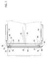
Figure 7 is a partially sectioned plan view of a clamping device indicated by the arrow VII inFigure 1 ; and -
Figure 8 is a view corresponding to that ofFigure 7 illustrating the clamping device in a position of disengagement. - With reference to
Figures 1 to 5 , designated by 10 is an armchair convertible into a chaise-longue according to the present invention. Thearmchair 10 comprises astationary base structure 12 having afront section 14 and arear section 16. Thebase structure 12 is shaped for resting on the floor. In the embodiment illustrated, thefront section 14 has twovertical elements 18 joined to one another by a bottomtransverse element 20 and by a toptransverse element 22. Therear section 16 has twovertical elements 24 joined to one another by a bottomtransverse element 26 and by a toptransverse element 28. The bottomtransverse elements front section 14 and of therear section 16 are joined to one another by means oflongitudinal elements 30. This specific conformation of thebase structure 12 is not, however, mandatory and may be varied according to considerations of a styling nature. - The
armchair 10 comprises a sittingunit 32 made up of aseat portion 34 and abackrest portion 36. Theseat portion 34 and thebackrest portion 36 are in a fixed position with respect to one another. Thesitting unit 32 is articulated to thefront section 14 of thebase structure 12 about ahorizontal axis 38 located at thefront edge 40 of theseat portion 34. - The articulation between the
sitting unit 32 and thefront section 14 of thebase structure 12 is preferably made as illustrated inFigure 6 . The axis ofarticulation 38 is defined by aligned holes for twopins 42 fixed to the toptransverse element 22 of thefront section 14. The sittingunit 32 is articulated to thepins 42 by means of twobrackets 44 fixed on the bottom surface of theseat portion 34, at itsfront edge 40. Thebrackets 44 are articulated to thepins 42 by means oftransverse pins 46 sharing the axis ofarticulation 38. As is illustrated inFigure 6 , thesitting unit 32 can be formed by arigid panel 48, on which apadding 50 is applied. - The rear part of the
sitting unit 32 is connected in a vertically mobile way to therear section 16 of thebase structure 12. Thevertical elements 24 of therear section 16 have a tubular shape and form two guides with vertical axis. Twomobile rods 52 are slidably engaged within thevertical elements 24. Themobile rods 52 are connected to one another by means of atransverse rod 54. The side ends of thetransverse rod 54 are bent forwards and bearrespective armrests 56. - With reference to
Figures 3 to 6 , thetransverse rod 54 engages in a mobile way twoelongated slots 58 formed inrespective brackets 60 fixed to the rear wall of thebackrest portion 36 of the sitting-surface unit 32. In one variant (not illustrated), each pair constituted by thebracket 60 and by theslot 58 may be replaced by a joint of elastic material, such as, for example, rubber or the like. Said joint connects thetransverse rod 54 to the rear surface of thepanel 48. The elasticity of the material enables a joint to be obtained with functional characteristics identical to the solution already described but visibly more essential and elegant. - A
clamping device 62 is set in therear section 16 of thebase structure 12. With reference in particular toFigures 7 and8 , theclamping device 62 comprises aclamping bar 64 axially mobile within thetop cross member 28 of therear section 16. Theclamping bar 64 has afirst end 68 that projects on the outside of thetop cross member 28. Anelastic element 70 acts between a closedend 72 of thetransverse element 28 and asecond end 74 of theclamping bar 64. Theelastic element 70 tends to push theclamping bar 64 towards the outside of thetop cross member 28. The clamping bar is equipped with a transverse pin (not visible in the drawings), which engages a longitudinal slot (which is not visible in the drawings either) of thetop cross member 28. The pin-slot coupling limits the travel of thebar 64, preventing this from being expelled from thetop cross member 28 by the thrust received from theelastic element 70. - The
clamping bar 64 has two portions of reduceddiameter 76 situated in the vicinity of theends top cross member 28 intersects thevertical elements 24 partially. When theelastic element 70 is in the extended position (Figure 7 ), theclamping bar 64 has two stretches adjacent to the portions of reduceddiameter 76 that extend partially within thevertical elements 24. When theelastic element 70 is in the compressed position (Figure 8 ), the portions of reduceddiameter 76 of theclamping bar 64 are positioned in the areas of intersection between thetop cross member 28 and thevertical elements 24. - Each
mobile rod 52 is equipped with at least one arrest notch (not visible in the drawings) with a shape complementary to the outer surface of theclamping bar 64. In the position illustrated inFigure 7 , the arrest notches of themobile rods 52 couple with the portions of theclamping bar 64 that extend within thevertical elements 24. In this condition, themobile rods 52 are clamped with respect to therear section 16 of thebase structure 12. By pressing axially on theends 68 of theclamping bar 64, the portions of reduceddiameter 76 of theclamping bar 64 move into a position corresponding to the vertical tubular elements 24 (configuration ofFigure 8 ). In this condition, themobile rods 52 are free to move vertically within thevertical elements 24. On themobile rods 52 there may be provided a plurality of arrest notches, staggered with respect to one another in a vertical direction, to each of which there corresponds a position of clamping of the sitting-surface unit 32 with respect to thestationary base structure 12. - With reference to
Figures 1 to 6 , thearmchair 10 comprises two foot-rest portions 78. Each of the foot-rest portions 78 is able to rotate with respect to thestationary base structure 12 about a respectivevertical axis 80 between an inoperative position, illustrated inFigures 1 ,3 and6 , and an operative position, illustrated inFigures 2 ,4 and5 . Each foot-rest portion 78 has apart 82, inclined with respect to a horizontal plane, that is radiused at one of its ends to a part for resting on thefloor 84. Each foot-rest portion 78 can, for example, be formed by a shaped rigid panel. - As is illustrated in
Figure 6 , the foot-rest portions 78 are preferably mounted so that they can turn about thesame pins 42 that define the horizontal axis ofarticulation 38 of the sitting-surface unit 32. The axes ofrotation 80 of the foot-rest portions 78 coincide with the axes of thepins 42 and are orthogonal with respect to the horizontal axis ofarticulation 38. Each foot-rest portion 78 can turn about the respectivevertical axis 80 by approximately 180° to pass from the inoperative position to the operative position, and vice versa. The rotation of the foot-rest portions 78 is governed manually by the user. Thearrows 86 inFigure 1 show the direction of rotation of the foot-rest portions 78 for passing from the inoperative position to the operative position. Thearrows 88 inFigure 2 show the direction of rotation of the foot-rest portions 78 for passing from the operative position to the inoperative position. -
Figures 1 and3 illustrate theconvertible armchair 10 according to the present invention in its use as armchair. In this configuration, the foot-rest portions 78 extend underneath theseat portion 34 of the sitting-surface unit 32. -
Figures 2 ,4 and5 illustrate the convertible armchair according to the present invention in the chaise-longue configuration. In this configuration, the foot-rest portions 78 extend forwards beyond thefront edge 40 of theseat portion 34. It may be noted that theseat portion 34 and theinclined part 82 of the foot-rest portions 78 are inclined with respect to a horizontal plane in directions opposite to one another. When the user is sitting on the armchair in the chaise-longue configuration, his knees are positioned at thefront edge 40 of theseat portion 34 and are in a raised position with respect to the pelvis and to the feet, according to the typical position of a chaise-longue. - In the chaise-longue configuration, it is possible to vary the inclination backwards of the sitting-
surface unit 32.Figures 4 and5 illustrate the sitting-surface unit 32 in a raised position and in a position reclined backwards, respectively. In the configuration ofFigure 4 , the sitting-surface unit 32 is kept in the raised position by the clampingdevice 62. To recline the sitting-surface unit 32 backwards, the clampingdevice 62 is disengaged by pressing on theend 68 of the clampingbar 64. After disengaging theclamping device 62, it is possible to slide the verticallymobile rods 52 downwards, thus bringing the sittingunit 32 into the position where it is reclined backwards, as illustrated inFigure 5 . As mentioned previously, it is possible to provide a plurality of positions with different inclinations by providing on the mobile rods 52 a plurality of arrest notches staggered with respect to one another in a vertical direction.
Claims (9)
- An armchair convertible into a chaise-longue, comprising:- a stationary base structure (12) having a front section (14) and a rear section (16);- a sitting unit (32) including a seat portion (34) and a backrest portion (36) in a fixed position with respect to one another, wherein the sitting unit (32) is articulated to the front section (14) of the base structure (12) about a horizontal axis (38) and is mobile between a raised position and at least one a position inclined backwards, wherein in each of said positions the seat portion (34) is inclined with respect to a horizontal plane;- a clamping device (62) set in the rear section (16) of the base structure (12), arranged to withhold the sitting unit (32) in at least one of said positions; and- two foot-rest portions (78), each of which is articulated to the front section (14) of the base structure (12) about a respective vertical axis (80) and is able to rotate between an inoperative position and an operative position, wherein, in the inoperative position, each foot-rest portion (78) extends underneath said seat portion (34) of the sitting-surface unit (32) and wherein, in the operative position, each foot-rest portion (78) extends forwards beyond a front edge (40) of the seat portion (34) and has an inclination with respect to a horizontal plane opposite to the inclination of the seat portion (34).
- The armchair according to Claim 1, wherein each of said foot-rest portions (78) has a respective end (84) configured for resting on the floor.
- The armchair according to Claim 1, wherein the axis of articulation (80) of each of said foot-rest portions (78) is orthogonal to the axis of articulation (38) of the sitting unit (32).
- The armchair according to Claim 1, wherein the front section (14) of the base structure (12) comprises a transverse element (22) to which two vertical pins (42) are fixed, which define said vertical axes of rotation (80) of the foot-rest portions (78) and moreover define said horizontal axis of articulation (38) of the sitting unit (32).
- The armchair according to Claim 1, wherein the rear section (16) of the base structure (12) comprises two vertical tubular elements (24) in which respective vertically mobile rods (52) associated to the sitting unit (32) and co-operating with said clamping device (62) are engaged.
- The armchair according to Claim 5, wherein said vertically mobile rods (52) are connected to one another by means of a transverse rod (54) having side ends that engage a slot (58) fixed with respect to the backrest portion (36) of the sitting unit (32).
- The armchair according to Claim 6, wherein said transverse bar (54) carries at its side ends two armrests (56).
- The armchair according to Claim 5, wherein said clamping device (62) comprises a clamping bar (64) mobile within a transverse tubular element (28) fixed to said vertical elements (24) of the rear section (16).
- The armchair according to Claim 8, wherein said clamping bar (64) co-operates with an elastic element (70) and is axially mobile between a position of clamping and a position of release, wherein each of said vertically mobile rods (52) has at least one arrest notch, designed to co-operate with said arrest bar (64).
Priority Applications (4)
| Application Number | Priority Date | Filing Date | Title |
|---|---|---|---|
| EP09425019A EP2210526A1 (en) | 2009-01-27 | 2009-01-27 | An armchair convertible into a chaise-longue |
| EP09171577A EP2213203B1 (en) | 2009-01-27 | 2009-09-29 | A chair convertible into a chaise-longue |
| AT09171577T ATE538687T1 (en) | 2009-01-27 | 2009-09-29 | ARMCHAIR CONVERTIBLE INTO A CHAISEL LONGUE |
| US12/694,611 US8205936B2 (en) | 2009-01-27 | 2010-01-27 | Chair convertible into a chaise-lounge |
Applications Claiming Priority (1)
| Application Number | Priority Date | Filing Date | Title |
|---|---|---|---|
| EP09425019A EP2210526A1 (en) | 2009-01-27 | 2009-01-27 | An armchair convertible into a chaise-longue |
Publications (1)
| Publication Number | Publication Date |
|---|---|
| EP2210526A1 true EP2210526A1 (en) | 2010-07-28 |
Family
ID=40793170
Family Applications (2)
| Application Number | Title | Priority Date | Filing Date |
|---|---|---|---|
| EP09425019A Withdrawn EP2210526A1 (en) | 2009-01-27 | 2009-01-27 | An armchair convertible into a chaise-longue |
| EP09171577A Not-in-force EP2213203B1 (en) | 2009-01-27 | 2009-09-29 | A chair convertible into a chaise-longue |
Family Applications After (1)
| Application Number | Title | Priority Date | Filing Date |
|---|---|---|---|
| EP09171577A Not-in-force EP2213203B1 (en) | 2009-01-27 | 2009-09-29 | A chair convertible into a chaise-longue |
Country Status (3)
| Country | Link |
|---|---|
| US (1) | US8205936B2 (en) |
| EP (2) | EP2210526A1 (en) |
| AT (1) | ATE538687T1 (en) |
Families Citing this family (9)
| Publication number | Priority date | Publication date | Assignee | Title |
|---|---|---|---|---|
| CN102026608B (en) * | 2008-05-16 | 2015-01-14 | 易生股份公司 | Device for assisting childbirth |
| US8905483B2 (en) * | 2012-11-12 | 2014-12-09 | Compass Designs LLC | Adjustable footrest |
| US8926009B1 (en) * | 2013-07-23 | 2015-01-06 | La-Z-Boy Incorporated | Covered leg rest linkage for furniture member |
| US10051965B2 (en) * | 2015-04-03 | 2018-08-21 | Hewitt Design Group, LLC | Modified footrest for salon chair |
| USD783299S1 (en) * | 2015-08-20 | 2017-04-11 | Landscape Forms, Inc. | Lounge chair |
| WO2017046807A1 (en) * | 2015-09-18 | 2017-03-23 | Mindblowers Limited | Transformable chair |
| USD898391S1 (en) * | 2019-01-29 | 2020-10-13 | S.R. Smith, Llc | Lounger chair |
| USD909774S1 (en) * | 2019-09-11 | 2021-02-09 | Eric Jacoby Design, Inc. | Lounge chair |
| USD919315S1 (en) | 2020-01-14 | 2021-05-18 | S.R. Smith, Llc | Lounger chair |
Citations (6)
| Publication number | Priority date | Publication date | Assignee | Title |
|---|---|---|---|---|
| BE355819A (en) * | ||||
| US252169A (en) * | 1882-01-10 | Gynecological chair | ||
| US3137528A (en) * | 1960-06-15 | 1964-06-16 | Merton M Bottemiller | Chair with foot rest |
| DE9400625U1 (en) * | 1994-01-15 | 1994-03-31 | Mueller Herbert | Sun lounger |
| US5927812A (en) * | 1998-06-29 | 1999-07-27 | Telescope Casual Furniture Company | Reclinable outdoor chair |
| DE102006051289A1 (en) * | 2006-10-26 | 2008-04-30 | Appeltshauser, Georg, Dipl.-Ing. | Furniture e.g. sofa, has overlays supported on carrier, which is supported on frame and adjustable around perpendicular axis, where carrier includes adjusting unit for adjusting height of overlays relative to carrier |
Family Cites Families (21)
| Publication number | Priority date | Publication date | Assignee | Title |
|---|---|---|---|---|
| US376256A (en) * | 1888-01-10 | Chair | ||
| US439088A (en) * | 1890-10-28 | Chair | ||
| US834376A (en) * | 1905-02-06 | 1906-10-30 | John Flindall | Chair. |
| US1262216A (en) * | 1915-07-16 | 1918-04-09 | Wilbert L Smith | Adjustable foot-rest for chairs. |
| US1911116A (en) * | 1930-05-26 | 1933-05-23 | Guttin Harry | Convertible chair and chaise-lounge |
| US3007738A (en) * | 1958-12-16 | 1961-11-07 | Gardel Robert | Extension leg rest for chairs and the like |
| US3046050A (en) * | 1960-09-08 | 1962-07-24 | Fowler Hugh | Convertible chair |
| US3227439A (en) * | 1962-05-10 | 1966-01-04 | Simmons Co | Operating table having separable top |
| US3318596A (en) * | 1964-05-15 | 1967-05-09 | American Sterilizer Co | Surgical table |
| US4373222A (en) * | 1980-01-28 | 1983-02-15 | Enhancement Systems, Inc. | Prosthetic bench |
| US4940286A (en) * | 1988-10-18 | 1990-07-10 | Nguti Tallam I | Bed attachment and piece of furniture device |
| US5120071A (en) * | 1991-03-12 | 1992-06-09 | Eld-Arondak, Inc. | Adirondack chair for elderly people |
| IT222726Z2 (en) * | 1991-09-17 | 1995-04-24 | Magix Snc Di Xodo Gino & C | STRUCTURE OF ARMCHAIR OR SOFA WITH ACCESSORY FOOTSTOOLS OR SIMILAR |
| AU1385399A (en) * | 1997-11-07 | 1999-05-31 | Hill-Rom, Inc. | Surgical table apparatus |
| US6378149B1 (en) * | 1999-01-25 | 2002-04-30 | Steris Inc | Radiolucent split-leg accessory for a surgical table |
| US6101652A (en) * | 1999-09-08 | 2000-08-15 | Matern, Jr.; Maximillian | Stirrups |
| DE10253906A1 (en) * | 2002-11-19 | 2004-06-03 | Maquet Gmbh & Co. Kg | Leg plate arrangement for operating tables |
| US20040133979A1 (en) * | 2003-01-13 | 2004-07-15 | Newkirk David C. | Orthopedic table apparatus |
| EP1733647A1 (en) * | 2005-06-17 | 2006-12-20 | Pro-Cord S.P.A. | Chair convertible into chaise-longue |
| US20090127892A1 (en) * | 2007-11-21 | 2009-05-21 | Huei-Mei Chen | Chair capable of being adjusted as a chaise |
| US7896442B2 (en) * | 2008-05-30 | 2011-03-01 | White William L | Method and apparatus to ingress and egress of chair |
-
2009
- 2009-01-27 EP EP09425019A patent/EP2210526A1/en not_active Withdrawn
- 2009-09-29 AT AT09171577T patent/ATE538687T1/en active
- 2009-09-29 EP EP09171577A patent/EP2213203B1/en not_active Not-in-force
-
2010
- 2010-01-27 US US12/694,611 patent/US8205936B2/en not_active Expired - Fee Related
Patent Citations (6)
| Publication number | Priority date | Publication date | Assignee | Title |
|---|---|---|---|---|
| BE355819A (en) * | ||||
| US252169A (en) * | 1882-01-10 | Gynecological chair | ||
| US3137528A (en) * | 1960-06-15 | 1964-06-16 | Merton M Bottemiller | Chair with foot rest |
| DE9400625U1 (en) * | 1994-01-15 | 1994-03-31 | Mueller Herbert | Sun lounger |
| US5927812A (en) * | 1998-06-29 | 1999-07-27 | Telescope Casual Furniture Company | Reclinable outdoor chair |
| DE102006051289A1 (en) * | 2006-10-26 | 2008-04-30 | Appeltshauser, Georg, Dipl.-Ing. | Furniture e.g. sofa, has overlays supported on carrier, which is supported on frame and adjustable around perpendicular axis, where carrier includes adjusting unit for adjusting height of overlays relative to carrier |
Also Published As
| Publication number | Publication date |
|---|---|
| US8205936B2 (en) | 2012-06-26 |
| EP2213203A1 (en) | 2010-08-04 |
| US20100187890A1 (en) | 2010-07-29 |
| ATE538687T1 (en) | 2012-01-15 |
| EP2213203B1 (en) | 2011-12-28 |
Similar Documents
| Publication | Publication Date | Title |
|---|---|---|
| EP2210526A1 (en) | An armchair convertible into a chaise-longue | |
| RU2662092C2 (en) | Vehicle seating assembly (versions) | |
| US20080084102A1 (en) | Seating furniture item, in particular office chair | |
| CN105455480A (en) | Headrest tilt mechanism | |
| US4410215A (en) | Retractable leg rest for a chair | |
| CA2976305C (en) | Furniture member with legrest extension | |
| EP2832263B1 (en) | Chair | |
| CN108621891B (en) | Leg support options for recumbent seats | |
| AU2009336100A1 (en) | Adjustable headrest assembly for furniture member | |
| US20090236886A1 (en) | Swing assembly | |
| CA2857616C (en) | Furniture member with center support leg rest | |
| CN104487284A (en) | Fold and kneel seat with rearward folding motion | |
| CN203424654U (en) | Backrest adjusting mechanism of high-foot dining chair for infants and kids | |
| US7431397B2 (en) | Chair | |
| EP1736077B1 (en) | Relaxation chair | |
| CN210810072U (en) | Chair assembly structure | |
| EP1733647A1 (en) | Chair convertible into chaise-longue | |
| KR101328594B1 (en) | Chair including a structure enable to be interlocking between back part and footrest part | |
| CN111634320B (en) | Baby carrier | |
| US20110289680A1 (en) | Furniture for Adjustment into a Standing Up Assistance Position | |
| CN105815963A (en) | Child dining chair | |
| WO2011107005A1 (en) | Step tread regulating mechanism of baby stroller | |
| EP1712157A1 (en) | Mechanism for sofa-beds and the like | |
| CN212325905U (en) | Chair back folding mechanism and seat | |
| CN110558760B (en) | Chair assembly structure |
Legal Events
| Date | Code | Title | Description |
|---|---|---|---|
| PUAI | Public reference made under article 153(3) epc to a published international application that has entered the european phase |
Free format text: ORIGINAL CODE: 0009012 |
|
| AK | Designated contracting states |
Kind code of ref document: A1 Designated state(s): AT BE BG CH CY CZ DE DK EE ES FI FR GB GR HR HU IE IS IT LI LT LU LV MC MK MT NL NO PL PT RO SE SI SK TR |
|
| AX | Request for extension of the european patent |
Extension state: AL BA RS |
|
| AKY | No designation fees paid | ||
| REG | Reference to a national code |
Ref country code: DE Ref legal event code: R108 Effective date: 20110309 Ref country code: DE Ref legal event code: 8566 |
|
| STAA | Information on the status of an ep patent application or granted ep patent |
Free format text: STATUS: THE APPLICATION IS DEEMED TO BE WITHDRAWN |
|
| 18D | Application deemed to be withdrawn |
Effective date: 20110129 |