EP2228096A2 - Header assembly for implantable medical devices - Google Patents
Header assembly for implantable medical devices Download PDFInfo
- Publication number
- EP2228096A2 EP2228096A2 EP10002416A EP10002416A EP2228096A2 EP 2228096 A2 EP2228096 A2 EP 2228096A2 EP 10002416 A EP10002416 A EP 10002416A EP 10002416 A EP10002416 A EP 10002416A EP 2228096 A2 EP2228096 A2 EP 2228096A2
- Authority
- EP
- European Patent Office
- Prior art keywords
- electrical contact
- body portion
- elastomeric
- header
- header assembly
- Prior art date
- Legal status (The legal status is an assumption and is not a legal conclusion. Google has not performed a legal analysis and makes no representation as to the accuracy of the status listed.)
- Granted
Links
Images
Classifications
-
- H—ELECTRICITY
- H01—ELECTRIC ELEMENTS
- H01R—ELECTRICALLY-CONDUCTIVE CONNECTIONS; STRUCTURAL ASSOCIATIONS OF A PLURALITY OF MUTUALLY-INSULATED ELECTRICAL CONNECTING ELEMENTS; COUPLING DEVICES; CURRENT COLLECTORS
- H01R24/00—Two-part coupling devices, or either of their cooperating parts, characterised by their overall structure
- H01R24/58—Contacts spaced along longitudinal axis of engagement
-
- A—HUMAN NECESSITIES
- A61—MEDICAL OR VETERINARY SCIENCE; HYGIENE
- A61N—ELECTROTHERAPY; MAGNETOTHERAPY; RADIATION THERAPY; ULTRASOUND THERAPY
- A61N1/00—Electrotherapy; Circuits therefor
- A61N1/18—Applying electric currents by contact electrodes
- A61N1/32—Applying electric currents by contact electrodes alternating or intermittent currents
- A61N1/36—Applying electric currents by contact electrodes alternating or intermittent currents for stimulation
- A61N1/372—Arrangements in connection with the implantation of stimulators
- A61N1/375—Constructional arrangements, e.g. casings
- A61N1/3752—Details of casing-lead connections
-
- H—ELECTRICITY
- H01—ELECTRIC ELEMENTS
- H01R—ELECTRICALLY-CONDUCTIVE CONNECTIONS; STRUCTURAL ASSOCIATIONS OF A PLURALITY OF MUTUALLY-INSULATED ELECTRICAL CONNECTING ELEMENTS; COUPLING DEVICES; CURRENT COLLECTORS
- H01R13/00—Details of coupling devices of the kinds covered by groups H01R12/70 or H01R24/00 - H01R33/00
- H01R13/02—Contact members
- H01R13/15—Pins, blades or sockets having separate spring member for producing or increasing contact pressure
- H01R13/187—Pins, blades or sockets having separate spring member for producing or increasing contact pressure with spring member in the socket
-
- H—ELECTRICITY
- H01—ELECTRIC ELEMENTS
- H01R—ELECTRICALLY-CONDUCTIVE CONNECTIONS; STRUCTURAL ASSOCIATIONS OF A PLURALITY OF MUTUALLY-INSULATED ELECTRICAL CONNECTING ELEMENTS; COUPLING DEVICES; CURRENT COLLECTORS
- H01R24/00—Two-part coupling devices, or either of their cooperating parts, characterised by their overall structure
- H01R24/28—Coupling parts carrying pins, blades or analogous contacts and secured only to wire or cable
-
- H—ELECTRICITY
- H01—ELECTRIC ELEMENTS
- H01R—ELECTRICALLY-CONDUCTIVE CONNECTIONS; STRUCTURAL ASSOCIATIONS OF A PLURALITY OF MUTUALLY-INSULATED ELECTRICAL CONNECTING ELEMENTS; COUPLING DEVICES; CURRENT COLLECTORS
- H01R2105/00—Three poles
-
- H—ELECTRICITY
- H01—ELECTRIC ELEMENTS
- H01R—ELECTRICALLY-CONDUCTIVE CONNECTIONS; STRUCTURAL ASSOCIATIONS OF A PLURALITY OF MUTUALLY-INSULATED ELECTRICAL CONNECTING ELEMENTS; COUPLING DEVICES; CURRENT COLLECTORS
- H01R2201/00—Connectors or connections adapted for particular applications
- H01R2201/12—Connectors or connections adapted for particular applications for medicine and surgery
-
- Y—GENERAL TAGGING OF NEW TECHNOLOGICAL DEVELOPMENTS; GENERAL TAGGING OF CROSS-SECTIONAL TECHNOLOGIES SPANNING OVER SEVERAL SECTIONS OF THE IPC; TECHNICAL SUBJECTS COVERED BY FORMER USPC CROSS-REFERENCE ART COLLECTIONS [XRACs] AND DIGESTS
- Y10—TECHNICAL SUBJECTS COVERED BY FORMER USPC
- Y10T—TECHNICAL SUBJECTS COVERED BY FORMER US CLASSIFICATION
- Y10T29/00—Metal working
- Y10T29/49—Method of mechanical manufacture
- Y10T29/49002—Electrical device making
- Y10T29/49117—Conductor or circuit manufacturing
Definitions
- aspects of the disclosed embodiments relate to an in-line connector for conducting electrical signals between two different sources or nodes and more particularly to implantable medical devices (IMDs), specifically to headers for IMDs.
- IMDs implantable medical devices
- implantable medical devices provide electrical stimulation to body tissues, such as for monitoring or treating physiologic conditions and for providing alternative treatments to drugs.
- exemplary implantable medical devices include implantable cardio defibrillators, pacemakers, and programmable neurostimulator pulse generators, which are collectively referred to herein as implantable medical devices or IMDs.
- the IMDs typically incorporate a hermetically sealed device enclosing a power source and electronic circuitry, known as a can, and a header assembly connected to the can.
- Example IMDs are described in application Serial No. 11/839,103, filed on August 15, 2007 , entitled Connector Assembly for Use with Medical Devices; application Serial No. 12/062,895, filed on April 4, 2008 , entitled Connector Assembly for Use with Medical Devices; and application Serial No. 12/100,646, filed on April 10, 2008 , entitled Integrated Header Connector System. The contents of each of these applications are expressly incorporated herein by reference.
- header assembly that includes reduced spacing between contact elements and thus, a reduced overall size of the header assembly.
- medical lead cable is desirably detachable for implanting and programming purposes and for replacing the IMD when necessary.
- One aspect of the present header for implantable medical devices is to provide viable options for medical device manufacturers to reduce the overall dimensions of existing receptacles that otherwise may create manufacturing challenges.
- placing stackable rings between electrically insulating seals and positioning conductive contact elements between conductive grooves for forming a receptacle and integrating the contact assembly into the IMD are difficult, costly, and time consuming.
- a receptacle that not only meets the challenges associated with implantable applications but also is easier to manufacture than a variety of existing receptacles.
- One embodiment of the present header assembly for implantable medical devices comprises a body portion defining a plurality of openings spaced axially along the body portion; and a plurality of elastomeric walls interdisposed between adjacent openings to define cavities within the body portion, where each of the elastomeric walls defines an aperture passing axially through the body portion.
- the header also comprises a plurality of electrical contact rings each including an outer ring contact element and an electrical contact element housed in abutting engagement in an interior of the outer ring contact element. The electrical contact rings are configured to be positioned within the cavities such that adjacent elastomeric walls capture the electrical contact elements therebetween.
- the header assembly also comprises a first plurality of electrical contact rings positioned within the cavities between the elastomeric walls to form channels wherein the elastomeric walls form side walls of the channel and the electrical contact ring forms a base wall of the channel.
- the side walls are configured to capture a canted-coil spring housed within the electrical contact rings with no intervening portion of the electrical contact ring disposed between the canted-coil spring and the side walls.
- Another embodiment is a method of assembling a header for an implantable medical device which comprises providing a unitary body portion defining a plurality of openings spaced axially along the body portion, and a plurality of elastomeric walls interdisposed between the adjacent openings to define cavities within the body portion, where each elastomeric wall defines an aperture passing axially therethrough; inserting an electrical contact ring comprising an outer ring contact element and an electrical contact element housed in abutting engagement in an interior of the outer ring contact element into each cavity; and capturing the electrical contact elements within the elastomeric walls of the cavities with no intervening portion of the electrical contact ring disposed between the electrical contact element and the elastomeric walls.
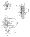
- Figure 1 is a front perspective view of an IMD including one embodiment of the present header, showing the header in partial section;
- Figure 2 is a front cross-sectional view of the IMD of Figure 1 , taken through the line 2-2 in Figure 1 ;
- Figure 2A is a detail view of the circled portion of the IMD of Figure 2 ;
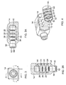
- Figure 3 is a left-side elevation view of the header of Figure 1 including electrical contact rings and a holding ring;
- Figure 3A is a front cross-sectional view of the components of Figure 3 , taken through the line A-A in Figure 3 ;
- Figure 3B is a top cross-sectional view of the components of Figure 3 , taken through the line B-B in Figure 3 ;
- Figure 4 is a front perspective view of the components of Figures 3-3B in a partially disassembled state.
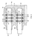
- Figure 5 is a cross-sectional view of an alternative IMD comprising a header having multiple connector assemblies.
- a header or header assembly for an IMD provides a means for electrically communicating, via an external medical lead cable, between the electronic circuits or power source located inside the device and the actual stimulation point.
- the header assembly includes a plurality of electrical contact elements, typically between three and seven, that are stacked in-line, or up to 14 or more in two rows.
- the contact elements are electrically coupled to the electronic circuits or to the power source located inside the can via conductive terminals.
- the contacts are separated electrically by dielectric insulator seals. The seals resist migration of body fluids into the spaces between the electrical contacts.
- Another desirable characteristic of the seals and possibly the contacts is adequate sealing force around the lead to maintain body fluid sealing to the lead while still providing acceptable insertion force.
- Other desirable characteristics of the IMD include reduced spacing between contact elements and reduced overall size of the header and IMD.
- a header assembly for an IMD There are two generally accepted methods of manufacturing a header assembly for an IMD.
- a plurality of connectors with elastomeric seals is over-molded with a polymer to form the header assembly.
- contacts inclusive of a housing and a spring are inserted into cavities pre-molded into an elastomeric header.
- the canted-coil springs of the contact elements have metal housing sidewalls to capture the springs.
- a feature of the present header is an in-line contact connector comprising a plurality of contact elements positioned in-line along a common bore and wherein the pitch, or spacing between two adjacent contact elements, is reduced compared to similar in-line contacts that have metal sidewalls.
- the elastomeric walls between contacts in the present embodiments achieve at least three advantages.
- the walls are dielectric insulators between contacts.
- the walls serve as elastomeric seals between contacts.
- the walls capture the canted-coil spring for each contact.
- one embodiment of the present implantable medical device 10 comprises a can 12.
- the can 12 houses a power source and electronic circuitry (not shown) and may be hermetically sealed to protect its contents.
- a header 14 including a body portion 16 adjoins the can 12.
- the header 14 includes a plurality of axially spaced openings 18 or slots, each of which may be appropriately sized and shaped to receive an electrical contact ring 20 or a holding ring 22.
- the contact rings 20 and the holding ring 22 are described in further detail below.
- electrical leads 24 extend between the power source in the can 12 and the contact rings 20.
- the leads 24 may project through one or more feed-through terminals (not shown) passing through the sealed can 12 to reach the contact rings 20.
- insulating rings 26 are interdisposed between the openings 18 to create and define internal cavities or sections 19 within the body portion 16.
- the insulating rings 26 separate the cavities 19 into sections and electrically isolate each contact ring 20 from a neighboring contact ring 20.
- the insulating rings 26 also seal against the lead cable 32, as discussed in further detail below. Accordingly, these components are referred to alternatively herein as insulating rings 26 and sealing rings 26.
- each insulating ring 26 substantially comprises a flat dividing wall 28 that defines a circular opening or aperture 30 at or near its center.
- the circular openings 30 are axially aligned along a common bore.
- the insulating rings 26 are molded integrally with the header body portion 16.
- the header 14 comprises a body portion that defines a plurality of openings 18 spaced axially along the body portion 16.
- the plurality of insulating rings 26 interdisposed between adjacent openings 18 create and define the cavities or sections 19 within the body portion 16.
- the insulating rings 26 each define an aperture 30 that passes axially through the insulating rings.
- the electrical contact rings 20 are configured to be inserted into the openings 18 and positioned within the cavities 19 between the dividing walls 28 of the insulating rings 26.
- a channel is formed that has the electrical contact ring 20 as a base wall of the channel and the dividing walls 28 on either side of the electrical contact ring 20 forming side walls of the channel.
- the channel is configured to capture and retain an electrical contact element 54, but without the use or the need for metal or otherwise conductive housing side walls.
- the header 14, contact rings 20, insulating rings 26 and holding ring 22 may comprise a connector assembly configured to receive a lead cable 32, as shown in Figures 1 and 2 , such as a medical lead cable comprising electrode leads.
- a lead cable 32 such as a medical lead cable comprising electrode leads.
- the illustrated connector assembly includes three contact rings 20 and three insulating rings 26, the present embodiments are not limited to any particular number of contact rings 20 or insulating rings 26.
- the lead cable 32 includes a plurality of ring-shaped electrical terminals 34 interposed between a plurality of ring-shaped lead insulators 36.
- the electrical terminals 34 engage the electrical contact elements 54 and the lead insulators 36 engage the insulating rings 26.
- a first end portion 38 of the lead cable 32 is received within a recess 40 ( Figure 3A ) defined in an end wall of the body portion 16 of the header 14.
- the first end portion 38 includes an annular groove 42 ( Figure 1 ) configured to receive a lead locking device 44, such as a set screw.
- the set screw 44 extends through a threaded opening 46 in the holding ring 22 ( Figure 4 ) and into the annular groove 42, as shown in Figure 1 . When tightened, the lead locking device 44 resists the withdrawal of the lead cable 32 from the header 14 in the axial direction.
- the holding ring 22 is shown as being located at the end wall of the header 14, it may be located anywhere along the header 14, including at the opposite end.
- the lead cable 32 further comprises a lead body 48, which carries a plurality of electrode leads 50. Ends (not shown) of the electrode leads 50 have electrode terminals (not shown) for providing electrical stimulation to body tissues at one or more locations remote from the IMD 10.
- the number of electrode leads 50 and the corresponding numbers of electrode terminals, electrical terminals 34 and contact rings 20 may vary depending on the particular application for which the IMD 10 is designed. Accordingly, applications of the IMDs 10 discussed herein include unipolar, bipolar, and multi-polar applications including varying numbers of components.
- each of the contact rings 20 comprises an outer ring contact element 52 and a canted-coil spring contact element 54 housed in abutting engagement in the interior of the outer ring contact element 52.
- each outer ring contact element 52 has a height (measured in the axial direction) that is substantially equal to the height of its respective canted-coil spring contact element 54.
- these components may have differing heights so that the outer ring contact element 52 biases the spring contact element 54.
- the coils of the canted-coil spring contact element 54 are substantially circular.
- the coils could be shaped differently, such as oval, elliptical, square, and the like.
- the outer ring contact element 52 and the canted-coil spring contact element 54 are each constructed of conductive materials and each outer ring contact element 52 is in electrical contact with its respective canted-coil spring contact element 54.
- the ring contact elements 52 are each configured to pass an electrical signal from one of the electrical leads 24 to their corresponding outer ring contact element 52 and canted-coil spring contact element 54, which then passes the electrical signal to a corresponding electrical terminal 34 on the lead cable 32, and then onto a corresponding electrode lead 50 located inside the lead body 48, and then to a corresponding electrode terminal on the distal end of the lead cable 32.
- the spring contact elements 54 may comprise canted-coil springs.
- the springs may be radially canted, while in certain other embodiments the springs may be axially canted. In still further embodiments, the springs may be both radially canted and axially canted.
- Canted-coil springs are described in detail in U.S. Patent Nos. 4,655,462 ; 4,826,144 ; 4,876781 ; 4,907,788 ; 4,915,366 ; 4,964,204 ; 5,139,243 ; 5,160,122 ; 5,503,375 ; 5,615,870 ; 5,709,371 ; 5,791,638 ; and 7,055,812 .
- the contents of each of the foregoing patents are hereby expressly incorporated by reference herein.
- the ring contact elements 52 are each generally cylindrical in configuration.
- each ring contact elements 52 has a generally constant inner diameter and outer diameter with two square ends, with normal manufacturing tolerance being acceptable.
- the ring contact elements 52 do not have machined or formed grooves for forming contact grooves therein for accommodating the spring contact elements 54.
- the ring contact elements 52 have a simple profile, which in one embodiment is tubular in shape and makes manufacturing the contact rings 20 and assembling the spring contact elements 54 therein easier and therefore more cost effective.
- the ring contact elements 52 inside diameter may include a groove in the area of the spring contact elements 54 so that two points of contact are available for the spring contact elements 54 versus one.
- the ring contact elements 52 may have a thicker section so that there are at least two internal diameters.
- the spring contact elements 54 can then be inserted through the larger internal diameter end of the ring contact elements 52 until it abuts the shoulder formed at the intersection between the two different internal diameters.
- different diameters and undulating internal surfaces for the ring contact elements 52 are contemplated.
- the ring with a grooved internal surface can be considered a subspecies of a ring having at least two internal diameters.
- the plurality of ring contact elements 52 in a single connector assembly may be non-uniform.
- one embodiment may include a grooved ring at a first end of the connector assembly and smooth rings for the remaining ring contact elements 52.
- a ring with two different internal diameters may be combined with a grooved ring and with rings having uniform internal diameters.
- ring contact elements 52 provided herein can have not only a smooth internal diameter, but also machined surfaces and undulating surfaces.
- the header 14 includes a protruding portion 56 at a first end.
- the protruding portion 56 is substantially cylindrical and coaxial with the openings 30 in the insulating rings 26 ( Figure 3A ).
- an inner surface 58 of the protruding portion 56 includes a non-tapered region 60 adjacent an outward opening 62 in the protruding portion 56 and a tapered region 64 spaced from the outward opening 62.
- the tapered region 64 tapers outwardly with increasing distance from the outward opening 62.
- the outward taper reduces the contact area between the protruding portion 56 and the lead cable 32, thus reducing frictional resistance to insertion and removal of the lead cable 32 with respect to the header 14.
- An inwardly projecting ring 66 ( Figure 3A ) just inside the outward opening 62 forms an outermost insulating ring 26 that maintains a seal around the lead cable 32 to resist intrusion of bodily fluids into the IMD 10.
- the header 14 may be formed as a unitary piece in which the insulating rings 26 are integrally formed with the header body 16.
- the header 14 may be injection molded from a polymeric and/or elastomeric material, such as epoxy or silicone.
- the electrical contact rings 20 and the holding ring 22 are subsequently inserted through the openings 18 and into the spaced cavities 19 as shown in Figure 4 , and the cavities 19 and/or openings 18 may then be back-filled using a curable and implantable material.
- the header 14 is thus formed separately from the contact rings 20, and the two are subsequently combined.
- the insulating rings 26 preferably engage the electrical contact rings 20 and the holding ring 22 in a snug fit or an interference fit so that there are no gaps between these components through which bodily fluids may penetrate to the lead cable 32.
- a unitary body portion defining a plurality of openings spaced axially along a body portion and a plurality of elastomeric walls interdisposed between the adjacent openings defining cavities within the body portion is provided.
- Electrical contact rings each comprising an outer ring contact element and an electrical contact element housed in abutting engagement in an interior of the outer ring contact element are placed into each cavity. The insertion of the contact rings allows the capturing of electrical contact elements within the elastomeric walls of the cavities with no intervening portion of the electrical contact ring disposed between the electrical contact element and the elastomeric walls.
- the ring contact elements are shorter along an axial direction than comparable ring contact elements with ring contact sidewalls. Also by not incorporating ring contact sidewalls, the pitch or distance between two adjacent ring contact elements inside the header are shorter along the axial direction than comparable ring contact elements with ring contact sidewalls. This in turn allows for higher density or number of ring contact elements to be included in the header than ones having comparable ring contact elements with contact sidewalls. Furthermore, by having a higher density header, more electrode terminals may be incorporated with the medical lead cable for electrical stimulation of body tissues.
- the header 14 engages an end of the can 12 as shown in Figure 1 .
- the header 14 may be secured to the can 12 prior to the contact rings 20 being inserted into the cavities 19, or vice versa.
- the electrical leads 24 are placed as shown in Figures 1 and 3B after the header 14 is secured to the can 12 and the contact rings 20 are inserted into the cavities 19. This order of assembly steps prevents the electrical leads 24 from interfering with passage of the contact rings 20 into the cavities 19.
- the electrical leads 24 are placed such that each contacts a respective electrical contact ring 20.
- the lead cable 32 is inserted into the header 14 as shown in Figures 1 and 2 such that the insulating rings 26 engage the lead insulators 36 and the turns of the spring contact elements 54 bear against the lead electrical terminals 34.
- the insulating rings 26 preferably engage the lead cable 32 in an interference fit to resist the penetration of bodily fluids into the interior of the header 14.
- the interference fit may be about 0.001" or 0.002" radially.
- the spring contact elements 54 are sized so that each is deflected by the lead cable 32.
- the deflection is about 5% and up to about 50% of the spring contact elements' 54 total radial deflection, with up to about 40% being preferred. This deflection range ensures that a sufficient spring contact force is generated between the ring contact elements 52 and the electrical terminals 34 on the lead cable 32 for transferring electric signals between the two.
- the lead locking device 44 is advanced into the threaded bore 46 in the holding ring 22 until the lead locking device 44 extends into the groove 42 in the lead cable 32, as shown in Figure 3B .
- the bore in the holding ring 22 may be smooth and the lead locking device may comprise a pin.
- each insulating ring 26 primarily deflects by compression in the radially outward direction. This type of deflection creates a relatively high insertion force. As is clear to a person of ordinary skill in the art, the force is increased in a multi-seal in-line connector application due to insertion force across each seal.
- the present embodiments reduce the insertion force by providing insulating rings 26 having a relatively high slenderness ratio.
- the slenderness ratio is defined as the ratio of the insulating ring's length to its width, where length is measured in the radial direction and width is measured in the axial direction.
- the slenderness ratio is preferably greater than 1:1, and more preferably greater than 2:1, in order to achieve the desired low insertion force.
- Such slenderness ratios enable the insulating rings 26 to deflect a greater axial amount than conventional insulating rings.
- Such slenderness ratios further enable the insulating rings 26 to have decreased radial compression and increased axial deflection as compared to conventional insulating rings.
- the present header 14 provides many advantages over prior art IMDs.
- the header 14 is comparatively easy to manufacture and assemble.
- the header body 16 is molded as a unitary piece with the sealing rings 26.
- the contact rings 20 are then inserted through the openings 18 and into the cavities 19 and the cavities 19 are back filled to retain the contact rings 20 within the cavities 19. In back filling the cavities, the openings 18 are closed by the back filled material.
- the lead cable 32 is then inserted and secured with the lead locking device 44. In this process there are no complex steps of aligning contact rings 20 or sealing rings 26 and maintaining alignment while the lead cable 32 is inserted.
- the integral sealing rings 26 are already aligned, and the contact rings 20 are simply slid into place where friction keeps them in place until the lead cable 32 is inserted.
- the reduction in complexity of assembly also advantageously reduces the cost of manufacture for the present header 14.
- a single connector assembly has thus far been described as being positioned inside the header 14; however, two or more connector assemblies may be positioned within the header if desired depending on the particular implant application.
- the connector assemblies may be stacked side-by-side relative to the can 12.
- an alternative header 14a may include connector assemblies stacked on top of one another relative to the can 12.
- each connector assembly includes the insulating rings 26 that separate the cavities 19 and electrically isolate each contact ring 20 from the neighboring contact rings 20.
- the insulating rings 26 also seal against the lead cable 32, as discussed above.
- Each insulating ring 26 substantially comprises the flat dividing wall 28 that defines the circular opening or aperture 30 at or near its center and axially aligned with the insulating ring 26.
- the insulating rings 26 are molded integrally with the header body.
- the header 14a with the contact rings 20, insulating rings 26 and holding ring 22 may comprise the plurality of connector assemblies stacked on to one another and configured to receive the medical lead cables 32.
- the alternative header body portion 16a is reconfigured to accommodate the plurality of connector assemblies disposed therein.
- the body portion 16a is formed having a plurality of protruding portions 56a at a first end of the header 14a that correspond to each connector assembly disposed in the header 14a.
- Each protruding portion 56a is formed substantially cylindrical and positioned coaxial with the openings 30 in the insulating rings 26 of each connector assembly.
- the protruding portions 56a are similar in all additional respects to the protruding portion 56 described above.
- an adequate space 17 of header body material is disposed between the connector assemblies to ensure adequate isolation between the stacked connector assemblies.
- Header 14a includes and accommodates electrical leads 24 that extend between the power source in the can 12 and the contact rings 20 of each connector assembly.
- the leads 24 may project through one or more feed-through terminals (not shown) passing through the sealed can 12 and positioned on either side of the header body 16a to reach the contact rings 20. Since it is understood that the header 14a may be formed having any number of contact rings per connector assembly, it is also understood that the header 14a is formed to include the appropriate number of the leads 24 needed to accommodate the number of contact rings 20.
Abstract
Description
- This is a regular utility application of provisional application Ser. No.
61/159,313 3 filed March 11, 2009 , the contents of which are expressly incorporated herein by reference. - Aspects of the disclosed embodiments relate to an in-line connector for conducting electrical signals between two different sources or nodes and more particularly to implantable medical devices (IMDs), specifically to headers for IMDs.
- Some implantable medical devices provide electrical stimulation to body tissues, such as for monitoring or treating physiologic conditions and for providing alternative treatments to drugs. Exemplary implantable medical devices include implantable cardio defibrillators, pacemakers, and programmable neurostimulator pulse generators, which are collectively referred to herein as implantable medical devices or IMDs. The IMDs typically incorporate a hermetically sealed device enclosing a power source and electronic circuitry, known as a can, and a header assembly connected to the can.
- Example IMDs are described in application Serial No.
11/839,103, filed on August 15, 2007 12/062,895, filed on April 4, 2008 12/100,646, filed on April 10, 2008 - Industry wide standards often exist for, among other things, the dimensions, size, pin spacing, diameter and the like for the header assembly and the medical lead cable. However, it is desirable to create a header assembly that includes reduced spacing between contact elements and thus, a reduced overall size of the header assembly. Furthermore, it is desirable to maintain good electrical contact during the life of the IMD, and to avoid disconnecting the medical lead cable from the receptacle located in the header. Yet the medical lead cable is desirably detachable for implanting and programming purposes and for replacing the IMD when necessary.
- The various embodiments of the present header for implantable medical devices have several features, no single one of which is solely responsible for their desirable attributes. Without limiting the scope of the present embodiments as expressed by the claims that follow, their more prominent features now will be discussed briefly. After considering this discussion, and particularly after reading the section entitled "Detailed Description" one will understand how the features of the present embodiments provide advantages, which include reduced complexity of manufacture and assembly, with concomitant cost savings.
- One aspect of the present header for implantable medical devices is to provide viable options for medical device manufacturers to reduce the overall dimensions of existing receptacles that otherwise may create manufacturing challenges. Among other things, placing stackable rings between electrically insulating seals and positioning conductive contact elements between conductive grooves for forming a receptacle and integrating the contact assembly into the IMD are difficult, costly, and time consuming. Accordingly, there is a need for a receptacle that not only meets the challenges associated with implantable applications but also is easier to manufacture than a variety of existing receptacles. There is also a need for a receptacle that is easily adaptable with existing implantable medical devices that are easier to manufacture than a variety of existing implantable medical devices. Further, it is desirable to reduce the size of the IMD and its header assembly.
- One embodiment of the present header assembly for implantable medical devices comprises a body portion defining a plurality of openings spaced axially along the body portion; and a plurality of elastomeric walls interdisposed between adjacent openings to define cavities within the body portion, where each of the elastomeric walls defines an aperture passing axially through the body portion. The header also comprises a plurality of electrical contact rings each including an outer ring contact element and an electrical contact element housed in abutting engagement in an interior of the outer ring contact element. The electrical contact rings are configured to be positioned within the cavities such that adjacent elastomeric walls capture the electrical contact elements therebetween.
- Another embodiment of the header assembly for an implantable medical device comprises a body portion defining a plurality of first openings spaced axially along the body portion; and a plurality of elastomeric walls interdisposed between the adjacent first openings to define first cavities within the body portion, where each elastomeric wall defines an aperture passing axially therethrough. The header assembly also comprises a first plurality of electrical contact rings positioned within the cavities between the elastomeric walls to form channels wherein the elastomeric walls form side walls of the channel and the electrical contact ring forms a base wall of the channel. The side walls are configured to capture a canted-coil spring housed within the electrical contact rings with no intervening portion of the electrical contact ring disposed between the canted-coil spring and the side walls.
- Another embodiment is a method of assembling a header for an implantable medical device which comprises providing a unitary body portion defining a plurality of openings spaced axially along the body portion, and a plurality of elastomeric walls interdisposed between the adjacent openings to define cavities within the body portion, where each elastomeric wall defines an aperture passing axially therethrough; inserting an electrical contact ring comprising an outer ring contact element and an electrical contact element housed in abutting engagement in an interior of the outer ring contact element into each cavity; and capturing the electrical contact elements within the elastomeric walls of the cavities with no intervening portion of the electrical contact ring disposed between the electrical contact element and the elastomeric walls.
- The various embodiments of the present header for implantable medical devices now will be discussed in detail with an emphasis on highlighting the advantageous features. These embodiments depict the novel and non-obvious header shown in the accompanying drawings, which are for illustrative purposes only. These drawings include the following figures, in which like numerals indicate like parts:
-
Figure 1 is a front perspective view of an IMD including one embodiment of the present header, showing the header in partial section; -
Figure 2 is a front cross-sectional view of the IMD ofFigure 1 , taken through the line 2-2 inFigure 1 ; -
Figure 2A is a detail view of the circled portion of the IMD ofFigure 2 ; -
Figure 3 is a left-side elevation view of the header ofFigure 1 including electrical contact rings and a holding ring; -
Figure 3A is a front cross-sectional view of the components ofFigure 3 , taken through the line A-A inFigure 3 ; -
Figure 3B is a top cross-sectional view of the components ofFigure 3 , taken through the line B-B inFigure 3 ; -
Figure 4 is a front perspective view of the components ofFigures 3-3B in a partially disassembled state; and -
Figure 5 is a cross-sectional view of an alternative IMD comprising a header having multiple connector assemblies. - The following detailed description describes the present embodiments with reference to the drawings. In the drawings, reference numbers label elements of the present embodiments. These reference numbers are reproduced below in connection with the discussion of the corresponding drawing features.
- A header or header assembly for an IMD provides a means for electrically communicating, via an external medical lead cable, between the electronic circuits or power source located inside the device and the actual stimulation point. Generally, the header assembly includes a plurality of electrical contact elements, typically between three and seven, that are stacked in-line, or up to 14 or more in two rows. The contact elements are electrically coupled to the electronic circuits or to the power source located inside the can via conductive terminals. The contacts are separated electrically by dielectric insulator seals. The seals resist migration of body fluids into the spaces between the electrical contacts. Another desirable characteristic of the seals and possibly the contacts is adequate sealing force around the lead to maintain body fluid sealing to the lead while still providing acceptable insertion force. Other desirable characteristics of the IMD include reduced spacing between contact elements and reduced overall size of the header and IMD.
- There are two generally accepted methods of manufacturing a header assembly for an IMD. In the first, a plurality of connectors with elastomeric seals is over-molded with a polymer to form the header assembly. In the second, contacts inclusive of a housing and a spring are inserted into cavities pre-molded into an elastomeric header. In both cases, the canted-coil springs of the contact elements have metal housing sidewalls to capture the springs. In the case of the over-molded header, there are separate seals and housing/spring contacts.
- Certain of the present embodiments avoid metal sidewalls for the housing to retain the spring and reduce the number of seals, for example by using the over-molded header concept. In reducing or eliminating the sidewalls, these embodiments reduce the spacing between contacts and the overall size of the header and IMD. Accordingly, a feature of the present header is an in-line contact connector comprising a plurality of contact elements positioned in-line along a common bore and wherein the pitch, or spacing between two adjacent contact elements, is reduced compared to similar in-line contacts that have metal sidewalls.
- By pre-molding an elastomeric header with individual cavities to accept contact elements, contact spacing can be reduced, as further discussed below. The elastomeric walls between contacts in the present embodiments achieve at least three advantages. First, the walls are dielectric insulators between contacts. Second, the walls serve as elastomeric seals between contacts. Third, the walls capture the canted-coil spring for each contact. These and other features and advantages of the present invention can be better understood in connection with the description, claims, and appended drawings.
- With reference to
Figures 1 and 2 , one embodiment of the present implantablemedical device 10 comprises acan 12. The can 12 houses a power source and electronic circuitry (not shown) and may be hermetically sealed to protect its contents. Aheader 14 including abody portion 16 adjoins thecan 12. With reference now toFigure 4 , theheader 14 includes a plurality of axially spacedopenings 18 or slots, each of which may be appropriately sized and shaped to receive anelectrical contact ring 20 or a holdingring 22. The contact rings 20 and the holdingring 22 are described in further detail below. - With reference to
Figures 1 and3B , electrical leads 24 extend between the power source in thecan 12 and the contact rings 20. The leads 24 may project through one or more feed-through terminals (not shown) passing through the sealed can 12 to reach the contact rings 20. - With reference to
Figures 1 and3A , insulatingrings 26 are interdisposed between theopenings 18 to create and define internal cavities orsections 19 within thebody portion 16. The insulating rings 26 separate thecavities 19 into sections and electrically isolate eachcontact ring 20 from a neighboringcontact ring 20. The insulating rings 26 also seal against thelead cable 32, as discussed in further detail below. Accordingly, these components are referred to alternatively herein as insulatingrings 26 and sealing rings 26. - With reference to
Figure 3A , each insulatingring 26 substantially comprises aflat dividing wall 28 that defines a circular opening oraperture 30 at or near its center. Thecircular openings 30 are axially aligned along a common bore. As described in further detail below, in certain of the present embodiments the insulatingrings 26 are molded integrally with theheader body portion 16. - Thus, the
header 14 comprises a body portion that defines a plurality ofopenings 18 spaced axially along thebody portion 16. The plurality of insulatingrings 26 interdisposed betweenadjacent openings 18 create and define the cavities orsections 19 within thebody portion 16. The insulating rings 26 each define anaperture 30 that passes axially through the insulating rings. The electrical contact rings 20 are configured to be inserted into theopenings 18 and positioned within thecavities 19 between the dividingwalls 28 of the insulating rings 26. As shown inFigure 2A , once the contact rings 20 are inserted between the dividingwalls 28, a channel is formed that has theelectrical contact ring 20 as a base wall of the channel and the dividingwalls 28 on either side of theelectrical contact ring 20 forming side walls of the channel. As described in greater detail below, the channel is configured to capture and retain anelectrical contact element 54, but without the use or the need for metal or otherwise conductive housing side walls. - Together, the
header 14, contact rings 20, insulatingrings 26 and holdingring 22 may comprise a connector assembly configured to receive alead cable 32, as shown inFigures 1 and 2 , such as a medical lead cable comprising electrode leads. Further, although the illustrated connector assembly includes three contact rings 20 and threeinsulating rings 26, the present embodiments are not limited to any particular number of contact rings 20 or insulating rings 26. - With reference again to
Figures 1 and 2 , thelead cable 32 includes a plurality of ring-shapedelectrical terminals 34 interposed between a plurality of ring-shapedlead insulators 36. When properly inserted within theheader 14, theelectrical terminals 34 engage theelectrical contact elements 54 and thelead insulators 36 engage the insulating rings 26. Afirst end portion 38 of thelead cable 32 is received within a recess 40 (Figure 3A ) defined in an end wall of thebody portion 16 of theheader 14. Thefirst end portion 38 includes an annular groove 42 (Figure 1 ) configured to receive alead locking device 44, such as a set screw. Theset screw 44 extends through a threadedopening 46 in the holding ring 22 (Figure 4 ) and into theannular groove 42, as shown inFigure 1 . When tightened, thelead locking device 44 resists the withdrawal of thelead cable 32 from theheader 14 in the axial direction. Although the holdingring 22 is shown as being located at the end wall of theheader 14, it may be located anywhere along theheader 14, including at the opposite end. - With reference to
Figure 1 , thelead cable 32 further comprises alead body 48, which carries a plurality of electrode leads 50. Ends (not shown) of the electrode leads 50 have electrode terminals (not shown) for providing electrical stimulation to body tissues at one or more locations remote from theIMD 10. The number of electrode leads 50 and the corresponding numbers of electrode terminals,electrical terminals 34 and contact rings 20 may vary depending on the particular application for which theIMD 10 is designed. Accordingly, applications of theIMDs 10 discussed herein include unipolar, bipolar, and multi-polar applications including varying numbers of components. - With reference to
Figure 2, Figure 2A andFigure 4 , each of the contact rings 20 comprises an outerring contact element 52 and a canted-coilspring contact element 54 housed in abutting engagement in the interior of the outerring contact element 52. In the illustrated embodiment (Figure 2A ), each outerring contact element 52 has a height (measured in the axial direction) that is substantially equal to the height of its respective canted-coilspring contact element 54. However, in alternative embodiments these components may have differing heights so that the outerring contact element 52 biases thespring contact element 54. Further, in the illustrated embodiment the coils of the canted-coilspring contact element 54 are substantially circular. However, in alternative embodiments the coils could be shaped differently, such as oval, elliptical, square, and the like. - The outer
ring contact element 52 and the canted-coilspring contact element 54 are each constructed of conductive materials and each outerring contact element 52 is in electrical contact with its respective canted-coilspring contact element 54. With reference toFigure 1 , thering contact elements 52 are each configured to pass an electrical signal from one of the electrical leads 24 to their corresponding outerring contact element 52 and canted-coilspring contact element 54, which then passes the electrical signal to a correspondingelectrical terminal 34 on thelead cable 32, and then onto a correspondingelectrode lead 50 located inside thelead body 48, and then to a corresponding electrode terminal on the distal end of thelead cable 32. - The
spring contact elements 54 may comprise canted-coil springs. In certain embodiments the springs may be radially canted, while in certain other embodiments the springs may be axially canted. In still further embodiments, the springs may be both radially canted and axially canted. Canted-coil springs are described in detail inU.S. Patent Nos. 4,655,462 ;4,826,144 ;4,876781 ;4,907,788 ;4,915,366 ;4,964,204 ;5,139,243 ;5,160,122 ;5,503,375 ;5,615,870 ;5,709,371 ;5,791,638 ; and7,055,812 . The contents of each of the foregoing patents are hereby expressly incorporated by reference herein. - With reference to
Figure 4 , in one embodiment thering contact elements 52 are each generally cylindrical in configuration. Thus, eachring contact elements 52 has a generally constant inner diameter and outer diameter with two square ends, with normal manufacturing tolerance being acceptable. In this embodiment, thering contact elements 52 do not have machined or formed grooves for forming contact grooves therein for accommodating thespring contact elements 54. Thering contact elements 52 have a simple profile, which in one embodiment is tubular in shape and makes manufacturing the contact rings 20 and assembling thespring contact elements 54 therein easier and therefore more cost effective. In other embodiments, thering contact elements 52 inside diameter may include a groove in the area of thespring contact elements 54 so that two points of contact are available for thespring contact elements 54 versus one. - Other geometries are also contemplated. For example, the
ring contact elements 52 may have a thicker section so that there are at least two internal diameters. Thespring contact elements 54 can then be inserted through the larger internal diameter end of thering contact elements 52 until it abuts the shoulder formed at the intersection between the two different internal diameters. Thus, different diameters and undulating internal surfaces for thering contact elements 52 are contemplated. The ring with a grooved internal surface can be considered a subspecies of a ring having at least two internal diameters. Still alternatively, the plurality ofring contact elements 52 in a single connector assembly may be non-uniform. For example, one embodiment may include a grooved ring at a first end of the connector assembly and smooth rings for the remainingring contact elements 52. Still alternatively, a ring with two different internal diameters may be combined with a grooved ring and with rings having uniform internal diameters. Thus,ring contact elements 52 provided herein can have not only a smooth internal diameter, but also machined surfaces and undulating surfaces. - With reference to
Figures 1 and 2 , theheader 14 includes a protrudingportion 56 at a first end. The protrudingportion 56 is substantially cylindrical and coaxial with theopenings 30 in the insulating rings 26 (Figure 3A ). As shown inFigure 3B , aninner surface 58 of the protrudingportion 56 includes anon-tapered region 60 adjacent anoutward opening 62 in the protrudingportion 56 and a taperedregion 64 spaced from theoutward opening 62. The taperedregion 64 tapers outwardly with increasing distance from theoutward opening 62. With reference toFigure 2 , the outward taper reduces the contact area between the protrudingportion 56 and thelead cable 32, thus reducing frictional resistance to insertion and removal of thelead cable 32 with respect to theheader 14. An inwardly projecting ring 66 (Figure 3A ) just inside theoutward opening 62 forms an outermost insulatingring 26 that maintains a seal around thelead cable 32 to resist intrusion of bodily fluids into theIMD 10. - As recited above, in the present embodiments the
header 14 may be formed as a unitary piece in which the insulatingrings 26 are integrally formed with theheader body 16. For example, theheader 14 may be injection molded from a polymeric and/or elastomeric material, such as epoxy or silicone. The electrical contact rings 20 and the holdingring 22 are subsequently inserted through theopenings 18 and into the spacedcavities 19 as shown inFigure 4 , and thecavities 19 and/oropenings 18 may then be back-filled using a curable and implantable material. Theheader 14 is thus formed separately from the contact rings 20, and the two are subsequently combined. Once combined, the insulatingrings 26 preferably engage the electrical contact rings 20 and the holdingring 22 in a snug fit or an interference fit so that there are no gaps between these components through which bodily fluids may penetrate to thelead cable 32. - Thus, in a method of assembling the header for an implantable medical device, a unitary body portion defining a plurality of openings spaced axially along a body portion and a plurality of elastomeric walls interdisposed between the adjacent openings defining cavities within the body portion is provided. Electrical contact rings each comprising an outer ring contact element and an electrical contact element housed in abutting engagement in an interior of the outer ring contact element are placed into each cavity. The insertion of the contact rings allows the capturing of electrical contact elements within the elastomeric walls of the cavities with no intervening portion of the electrical contact ring disposed between the electrical contact element and the elastomeric walls. By not incorporating ring contact sidewalls, the ring contact elements are shorter along an axial direction than comparable ring contact elements with ring contact sidewalls. Also by not incorporating ring contact sidewalls, the pitch or distance between two adjacent ring contact elements inside the header are shorter along the axial direction than comparable ring contact elements with ring contact sidewalls. This in turn allows for higher density or number of ring contact elements to be included in the header than ones having comparable ring contact elements with contact sidewalls. Furthermore, by having a higher density header, more electrode terminals may be incorporated with the medical lead cable for electrical stimulation of body tissues.
- The
header 14 engages an end of thecan 12 as shown inFigure 1 . During assembly of theIMD 10, theheader 14 may be secured to thecan 12 prior to the contact rings 20 being inserted into thecavities 19, or vice versa. Preferably, however, the electrical leads 24 are placed as shown inFigures 1 and3B after theheader 14 is secured to thecan 12 and the contact rings 20 are inserted into thecavities 19. This order of assembly steps prevents the electrical leads 24 from interfering with passage of the contact rings 20 into thecavities 19. The electrical leads 24 are placed such that each contacts a respectiveelectrical contact ring 20. - The
lead cable 32 is inserted into theheader 14 as shown inFigures 1 and 2 such that the insulatingrings 26 engage thelead insulators 36 and the turns of thespring contact elements 54 bear against the leadelectrical terminals 34. With reference toFigure 2A , the insulatingrings 26 preferably engage thelead cable 32 in an interference fit to resist the penetration of bodily fluids into the interior of theheader 14. In one embodiment, the interference fit may be about 0.001" or 0.002" radially. Similarly, thespring contact elements 54 are sized so that each is deflected by thelead cable 32. In one embodiment, the deflection is about 5% and up to about 50% of the spring contact elements' 54 total radial deflection, with up to about 40% being preferred. This deflection range ensures that a sufficient spring contact force is generated between thering contact elements 52 and theelectrical terminals 34 on thelead cable 32 for transferring electric signals between the two. - To secure the
lead cable 32 within theheader 14, thelead locking device 44 is advanced into the threaded bore 46 in the holdingring 22 until thelead locking device 44 extends into thegroove 42 in thelead cable 32, as shown inFigure 3B . Those of ordinary skill in the art will appreciate that in other embodiments the bore in the holdingring 22 may be smooth and the lead locking device may comprise a pin. - The interference fit described above creates friction on the
lead cable 32 that resists axial insertion of thelead cable 32 into theheader 14. With regard to the insulatingrings 26, in conventional IMDs each insulatingring 26 primarily deflects by compression in the radially outward direction. This type of deflection creates a relatively high insertion force. As is clear to a person of ordinary skill in the art, the force is increased in a multi-seal in-line connector application due to insertion force across each seal. - With reference to
Figures 3A and 3B , the present embodiments reduce the insertion force by providing insulatingrings 26 having a relatively high slenderness ratio. As used herein the slenderness ratio is defined as the ratio of the insulating ring's length to its width, where length is measured in the radial direction and width is measured in the axial direction. The slenderness ratio is preferably greater than 1:1, and more preferably greater than 2:1, in order to achieve the desired low insertion force. Such slenderness ratios enable the insulatingrings 26 to deflect a greater axial amount than conventional insulating rings. Such slenderness ratios further enable the insulatingrings 26 to have decreased radial compression and increased axial deflection as compared to conventional insulating rings. - The
present header 14 provides many advantages over prior art IMDs. For example, theheader 14 is comparatively easy to manufacture and assemble. Theheader body 16 is molded as a unitary piece with the sealing rings 26. The contact rings 20 are then inserted through theopenings 18 and into thecavities 19 and thecavities 19 are back filled to retain the contact rings 20 within thecavities 19. In back filling the cavities, theopenings 18 are closed by the back filled material. Thelead cable 32 is then inserted and secured with thelead locking device 44. In this process there are no complex steps of aligning contact rings 20 or sealing rings 26 and maintaining alignment while thelead cable 32 is inserted. The integral sealing rings 26 are already aligned, and the contact rings 20 are simply slid into place where friction keeps them in place until thelead cable 32 is inserted. The reduction in complexity of assembly also advantageously reduces the cost of manufacture for thepresent header 14. - A single connector assembly has thus far been described as being positioned inside the
header 14; however, two or more connector assemblies may be positioned within the header if desired depending on the particular implant application. In some embodiments, the connector assemblies may be stacked side-by-side relative to thecan 12. As shown in the embodiment ofFigure 5 , analternative header 14a may include connector assemblies stacked on top of one another relative to thecan 12. - In the alternative embodiment of
Figure 5 , it should be understood that the connector assemblies formed in thealternative header 14a each comprise the same components, to provide the same functions and operate in the same manner as described above with regard to the single connector assembly disposed inheader 14. As in previously described embodiments, each connector assembly includes the insulatingrings 26 that separate thecavities 19 and electrically isolate eachcontact ring 20 from the neighboring contact rings 20. The insulating rings 26 also seal against thelead cable 32, as discussed above. Each insulatingring 26 substantially comprises theflat dividing wall 28 that defines the circular opening oraperture 30 at or near its center and axially aligned with the insulatingring 26. As described in detail above, in certain embodiments the insulatingrings 26 are molded integrally with the header body. Theheader 14a with the contact rings 20, insulatingrings 26 and holdingring 22 may comprise the plurality of connector assemblies stacked on to one another and configured to receive themedical lead cables 32. - Although the connector assemblies are the same as described above, the alternative
header body portion 16a is reconfigured to accommodate the plurality of connector assemblies disposed therein. For example, in this embodiment, thebody portion 16a is formed having a plurality of protrudingportions 56a at a first end of theheader 14a that correspond to each connector assembly disposed in theheader 14a. Each protrudingportion 56a is formed substantially cylindrical and positioned coaxial with theopenings 30 in the insulatingrings 26 of each connector assembly. The protrudingportions 56a are similar in all additional respects to the protrudingportion 56 described above. - In the
body portion 16a ofheader 14a, anadequate space 17 of header body material is disposed between the connector assemblies to ensure adequate isolation between the stacked connector assemblies. -
Header 14a includes and accommodateselectrical leads 24 that extend between the power source in thecan 12 and the contact rings 20 of each connector assembly. The leads 24 may project through one or more feed-through terminals (not shown) passing through the sealed can 12 and positioned on either side of theheader body 16a to reach the contact rings 20. Since it is understood that theheader 14a may be formed having any number of contact rings per connector assembly, it is also understood that theheader 14a is formed to include the appropriate number of theleads 24 needed to accommodate the number of contact rings 20. - Although several embodiments of the
present header 14 for IMDs have been specifically described and illustrated, many modifications and variations will be apparent to those skilled in the art. For example, various material changes may be incorporated, such as making use of two or more different materials or composites, different mechanical engagement means may be used to attach the various components to one another, etc. Accordingly, it is to be understood that the present embodiments may be embodied in other ways than as specifically described herein. - The above description presents the best mode contemplated for carrying out the present header for implantable medical devices, and of the manner and process of making and using it, in such full, clear, concise, and exact terms as to enable any person skilled in the art to which it pertains to make and use this header. This header is, however, susceptible to modifications and alternate constructions from that discussed above that are fully equivalent. Consequently, this header is not limited to the particular embodiments disclosed. On the contrary, this header covers all modifications and alternate constructions coming within the spirit and scope of the header as generally expressed by the following claims, which particularly point out and distinctly claim the subject matter of the header.
Claims (18)
- A header assembly for an implantable medical device (IMD) comprising:a body portion defining a plurality of openings spaced axially along the body portion;a plurality of elastomeric walls interdisposed between adjacent openings to define cavities within the body portion, each elastomeric wall defining an aperture passing axially therethrough; anda plurality of electrical contact rings each comprising an outer ring contact element and an electrical contact element housed in abutting engagement in an interior of the outer ring contact element, and configured to be positioned within the cavities such that adjacent elastomeric walls capture the electrical contact elements therebetween.
- The header assembly of Claim 1, wherein the plurality of electrical contact rings are devoid of ring contact sidewalls.
- The header assembly of Claim 1, wherein the elastomeric walls comprise dielectric insulators.
- The header assembly of Claim 1, wherein the elastomeric walls comprise elastomeric seals for sealing against a lead cable.
- The header assembly of Claim 1, wherein the electrical contact element comprises a canted-coil spring.
- The header assembly of Claim 1, further comprising a protruding portion at a first end of the body portion, the protruding portion being substantially cylindrical and coaxial with the apertures.
- The header assembly of Claim 6, wherein the protruding portion comprises an inner surface including a non-tapered region adjacent an outward opening in the protruding portion and a tapered region spaced from the outward opening.
- The header assembly of Claim 7, further comprising an inwardly projecting ring located immediately inside the outward opening.
- The header assembly of Claim 1, wherein the body portion defines a plurality of second openings spaced axially along the body portion;
a plurality of elastomeric walls interdisposed between the adjacent second openings to define second cavities within the body portion, each elastomeric wall defining an aperture passing axially therethrough; and
a plurality of second electrical contact rings each comprising an outer ring contact element and an electrical contact element housed in abutting engagement in an interior of the outer ring contact element, and configured to be positioned within the second cavities such that the elastomeric walls capture the electrical contact elements therebetween. - A header assembly for an implantable medical device (IMD) comprising:a body portion defining a plurality of first openings spaced axially along the body portion;a plurality of elastomeric walls interdisposed between the adjacent first openings to define first cavities within the body portion, each elastomeric wall defining an aperture passing axially therethrough; anda first plurality of electrical contact rings positioned within the cavities between the elastomeric walls to form channels wherein the elastomeric walls form side walls of the channel and the electrical contact ring forms a base wall of the channel, the side walls configured to capture a canted-coil spring housed within the electrical contact rings with no intervening portion of the electrical contact ring disposed between the canted-coil spring and the side walls.
- The header assembly of Claim 1 or 10, wherein the body portion is configured to engage a sealed can of the IMD and to receive one or more lead cables.
- The header assembly of Claim 1 or 10, wherein the elastomeric walls are formed unitarily with the body portion.
- The header assembly of Claim 10, wherein the elastomeric walls comprise dielectric insulators and elastomeric seals between the electrical contact rings.
- The header assembly of Claim 10, further comprising:a protruding portion at a first end of the body portion, the protruding portion substantially cylindrical and coaxial with the apertures, wherein the protruding portion comprises an inner surface including a non-tapered region adjacent an outward opening in the protruding portion and a tapered region spaced from the outward opening, and an inwardly projecting ring immediately inside the outward opening that maintains a seal around a cable inserted into the outward opening.
- The header assembly of Claim 10, wherein the body portion defines a plurality of second openings spaced axially along the body portion; a plurality of elastomeric walls interdisposed between the adjacent second openings to define second cavities within the body portion, each elastomeric wall defining an aperture passing axially therethrough; and a second plurality of electrical contact rings positioned within the second cavities between the elastomeric walls to form channels wherein the elastomeric walls form side walls of the channel and the electrical contact ring forms a base wall of the channel, the side walls configured to capture the canted-coil springs housed within the electrical contact rings.
- A method of assembling a header for an implantable medical device (IMD) comprising:providing a unitary body portion defining a plurality of openings spaced axially along the body portion, and a plurality of elastomeric walls interdisposed between the adjacent openings to define cavities within the body portion, each elastomeric wall defining an aperture passing axially therethrough;inserting an electrical contact ring comprising an outer ring contact element and an electrical contact element housed in abutting engagement in an interior of the outer ring contact element into each cavity; andcapturing the electrical contact elements within the elastomeric walls of the cavities with no intervening portion of the electrical contact ring disposed between the electrical contact element and the elastomeric walls.
- The method of Claim 16 wherein the unitary body further comprises:a protruding portion at a first end of the unitary body portion, the protruding portion substantially cylindrical and coaxial with the apertures, wherein the protruding portion comprises an inner surface including a non-tapered region adjacent an outward opening in the protruding portion and a tapered region spaced from the outward opening, and an inwardly projecting ring immediately inside the outward opening that maintains a seal around a cable inserted into the outward opening.
- The method of Claim 16, further comprising:engaging the unitary body portion with a sealed can of an IMD; andreceiving one or more lead cables of the IMD for transmitting electrical pulses from the IMD to a location in a patient's body remote from the IMD.
Applications Claiming Priority (2)
| Application Number | Priority Date | Filing Date | Title |
|---|---|---|---|
| US15931309P | 2009-03-11 | 2009-03-11 | |
| US12/717,732 US8096838B2 (en) | 2009-03-11 | 2010-03-04 | Header assembly for implantable medical devices |
Publications (3)
| Publication Number | Publication Date |
|---|---|
| EP2228096A2 true EP2228096A2 (en) | 2010-09-15 |
| EP2228096A3 EP2228096A3 (en) | 2010-11-10 |
| EP2228096B1 EP2228096B1 (en) | 2012-07-11 |
Family
ID=42163724
Family Applications (1)
| Application Number | Title | Priority Date | Filing Date |
|---|---|---|---|
| EP10002416A Active EP2228096B1 (en) | 2009-03-11 | 2010-03-09 | Header assembly for implantable medical devices |
Country Status (2)
| Country | Link |
|---|---|
| US (1) | US8096838B2 (en) |
| EP (1) | EP2228096B1 (en) |
Cited By (2)
| Publication number | Priority date | Publication date | Assignee | Title |
|---|---|---|---|---|
| EP2567733A1 (en) | 2011-09-08 | 2013-03-13 | Sorin CRM SAS | Method for producing a connector head for a multipolar probe of an active implantable medical device |
| CN105491842A (en) * | 2014-10-01 | 2016-04-13 | 精能医学股份有限公司 | Shell structure of electronic device |
Families Citing this family (29)
| Publication number | Priority date | Publication date | Assignee | Title |
|---|---|---|---|---|
| WO2009058879A2 (en) * | 2007-10-29 | 2009-05-07 | Rms Company | Set screw-less pacemaker header with lead lock system |
| WO2012149021A2 (en) * | 2011-04-25 | 2012-11-01 | Aspect Solar Pte Ltd. | Replaceable solar bulb assembly for use with a solar receiver array |
| US11211741B2 (en) | 2011-06-03 | 2021-12-28 | Greatbatch Ltd. | Removable terminal pin connector for an active electronics circuit board for use in an implantable medical device |
| US9419424B2 (en) * | 2011-08-24 | 2016-08-16 | Abb Schweiz Ag | Switchgear bus support bushing structure |
| US9227076B2 (en) * | 2011-11-04 | 2016-01-05 | Nevro Corporation | Molded headers for implantable signal generators, and associated systems and methods |
| EP2773423B1 (en) | 2011-11-04 | 2024-01-10 | Nevro Corporation | Medical device communication and charding assemblies for use with implantable signal generators |
| AU2012352462B2 (en) * | 2011-12-13 | 2015-05-21 | Cardiac Pacemakers, Inc. | Implantable device header and method |
| AU2012362623B2 (en) * | 2011-12-28 | 2015-09-10 | Cardiac Pacemakers, Inc. | Toroidal compressible element including a switchback pattern |
| WO2013142734A1 (en) | 2012-03-21 | 2013-09-26 | Bal Seal Engineering, Inc. | Connectors with electrical or signal carrying capabilities and related methods |
| US9079020B2 (en) * | 2012-10-17 | 2015-07-14 | Cardiac Pacemakers, Inc. | Terminal ring configuration to prevent improper IS4 lead connector electrical contact with DF4 connector port |
| US8888537B2 (en) * | 2012-11-16 | 2014-11-18 | Apple Inc. | Audio jack with multiple points of contact |
| US10263368B2 (en) * | 2013-06-25 | 2019-04-16 | Bal Seal Engineering, Inc. | Electrical contacts with electrically conductive springs |
| US9724527B2 (en) | 2013-09-27 | 2017-08-08 | Cardiac Pacemakers, Inc. | Color coded header bore identification using multiple images and lens arrangement |
| US9306307B2 (en) * | 2014-01-29 | 2016-04-05 | Biotronik Se & Co. Kg | Contact element and method for producing a contact element |
| US9381368B2 (en) | 2014-03-05 | 2016-07-05 | Boston Scientific Neuromodulation Corporation | Lead connector assembly for an implantable medical device and method of construction |
| AU2015264561B2 (en) | 2014-05-20 | 2020-02-20 | Nevro Corporation | Implanted pulse generators with reduced power consumption via signal strength/duration characteristics, and associated systems and methods |
| WO2016064761A1 (en) | 2014-10-22 | 2016-04-28 | Nevro Corp. | Systems and methods for extending the life of an implanted pulse generator battery |
| US9517344B1 (en) | 2015-03-13 | 2016-12-13 | Nevro Corporation | Systems and methods for selecting low-power, effective signal delivery parameters for an implanted pulse generator |
| EP3374019B1 (en) | 2015-12-31 | 2021-12-22 | Nevro Corporation | Controller for nerve stimulation circuit and associated systems and methods |
| US10608354B2 (en) * | 2017-03-23 | 2020-03-31 | Verily Life Sciences Llc | Implantable connector with two electrical components |
| US11633604B2 (en) | 2018-01-30 | 2023-04-25 | Nevro Corp. | Efficient use of an implantable pulse generator battery, and associated systems and methods |
| EP3781257A4 (en) | 2018-05-01 | 2022-01-26 | Nevro Corp. | A 2.4 ghz radio antenna for implanted medical devices, and associated systems and methods |
| US10483690B1 (en) | 2018-09-10 | 2019-11-19 | Vadovations, Inc. | Electrical connector |
| US10741968B2 (en) * | 2018-09-10 | 2020-08-11 | Vadovations, Inc. | Electrical connector |
| DE102019207737B4 (en) * | 2019-01-28 | 2020-10-08 | Carl Haas Gmbh | Electrical contact arrangement for a first pole and a second pole of an electrical voltage source |
| US10933238B2 (en) | 2019-01-31 | 2021-03-02 | Nevro Corp. | Power control circuit for sterilized devices, and associated systems and methods |
| US11737689B2 (en) * | 2019-08-02 | 2023-08-29 | Bionime Corporation | Physiological signal monitoring device |
| CN114828953A (en) * | 2019-12-19 | 2022-07-29 | 心脏起搏器股份公司 | Connector for use in an overmolded head of an implantable pulse generator |
| CA214241S (en) * | 2021-09-30 | 2023-05-10 | Hopitaux Paris Assist Publique | ELECTROSTIMULATION DEVICE |
Citations (14)
| Publication number | Priority date | Publication date | Assignee | Title |
|---|---|---|---|---|
| US4655462A (en) | 1985-01-07 | 1987-04-07 | Peter J. Balsells | Canted coiled spring and seal |
| US4826144A (en) | 1988-04-25 | 1989-05-02 | Peter J. Balsells | Inside back angle canted coil spring |
| US4876781A (en) | 1988-04-25 | 1989-10-31 | Peter J. Balsells | Method of making a garter-type axially resilient coiled spring |
| US4907788A (en) | 1988-04-25 | 1990-03-13 | Peter J. Balsells | Dual concentric canted-coil spring apparatus |
| US4915366A (en) | 1988-04-25 | 1990-04-10 | Peter J. Balsells | Outside back angle canted coil spring |
| US4964204A (en) | 1988-04-25 | 1990-10-23 | Peter J. Balsells | Method for making a garter-type axially-resilient coil spring |
| US5139243A (en) | 1990-07-30 | 1992-08-18 | Peter J. Balsells | Axial canted coil springs in sinusoidal form |
| US5160122A (en) | 1990-03-20 | 1992-11-03 | Peter J. Balsells | Coil spring with an elastomer having a hollow coil cross section |
| US5503375A (en) | 1994-11-09 | 1996-04-02 | Bal Seal Engineering Company, Inc. | Coil spring with ends adapted for coupling without welding |
| US5709371A (en) | 1995-06-02 | 1998-01-20 | Bal Seal Engineering Company, Inc. | Coil spring with ends adapted for coupling without welding |
| US5791638A (en) | 1996-09-13 | 1998-08-11 | Bal Seal Engineering Company, Inc. | Coil spring with ends adapted for coupling without welding |
| US6289508B1 (en) | 1997-11-26 | 2001-09-11 | Voyan Technology | Method and apparatus for dynamic optimization |
| US7055812B2 (en) | 2002-09-30 | 2006-06-06 | Bal Seal Engineering Co., Inc. | Canted coil springs various designs |
| US10064608B2 (en) | 2014-11-18 | 2018-09-04 | Alec Goldenberg | Biopsy needle |
Family Cites Families (54)
| Publication number | Priority date | Publication date | Assignee | Title |
|---|---|---|---|---|
| US4072154A (en) | 1976-05-28 | 1978-02-07 | Cardiac Pacemakers, Inc. | Sealing arrangement for heart pacer electrode leads |
| FR2390031B1 (en) | 1977-05-06 | 1980-03-28 | Ela Medical Sa | |
| US4105037A (en) | 1977-05-06 | 1978-08-08 | Biotronik Mess- Und Therapiegerate Gmbh & Co. | Releasable electrical connecting means for the electrode terminal of an implantable artificial cardiac pacemaker |
| US4262673A (en) | 1979-10-11 | 1981-04-21 | Mieczyslaw Mirowski | Fluid tight coupling for electrode lead |
| US4461194A (en) | 1982-04-28 | 1984-07-24 | Cardio-Pace Medical, Inc. | Tool for sealing and attaching a lead to a body implantable device |
| US5070605A (en) * | 1988-04-22 | 1991-12-10 | Medtronic, Inc. | Method for making an in-line pacemaker connector system |
| US4934366A (en) | 1988-09-01 | 1990-06-19 | Siemens-Pacesetter, Inc. | Feedthrough connector for implantable medical device |
| US5132495A (en) * | 1991-01-23 | 1992-07-21 | Homac Mfg. Company | Submersible splice cover with resilient corrugated and sections |
| US5257622A (en) * | 1991-09-19 | 1993-11-02 | Medtronic, Inc. | Locking connector for implantable device |
| US5413595A (en) | 1993-10-15 | 1995-05-09 | Pacesetter, Inc. | Lead retention and seal for implantable medical device |
| US5817984A (en) | 1995-07-28 | 1998-10-06 | Medtronic Inc | Implantable medical device wtih multi-pin feedthrough |
| US7231253B2 (en) | 1997-08-01 | 2007-06-12 | Medtronic, Inc. | IMD connector header with grommet retainer |
| US7187974B2 (en) | 1997-08-01 | 2007-03-06 | Medtronic, Inc. | Ultrasonically welded, staked or swaged components in an implantable medical device |
| US6029089A (en) | 1998-07-10 | 2000-02-22 | Pacesetter, Inc. | Lead retention and sealing system |
| US6112121A (en) | 1998-09-09 | 2000-08-29 | Intermedics Inc. | Implantable medical device with positive indication of lead connection and connector therefor |
| US6039685A (en) | 1998-09-14 | 2000-03-21 | St. Croix Medical, Inc. | Ventable connector with seals |
| US6192277B1 (en) | 1999-07-06 | 2001-02-20 | Pacesetter, Inc. | Implantable device with bevel gear actuation for lead retention and actuation |
| DE10041728A1 (en) | 2000-08-25 | 2002-03-21 | Implex Hear Tech Ag | Implantable medicinal device with hermetically sealed housing has storage device accommodated directly within hermetically sealed housing without housing of its own |
| JP2002117584A (en) * | 2000-10-06 | 2002-04-19 | Sony Corp | Optical recording medium and its manufacturing method |
| US6498952B2 (en) | 2001-03-08 | 2002-12-24 | Pacesetter, Inc. | Hermetically sealed feedthrough connector using shape memory alloy for implantable medical device |
| US6428368B1 (en) | 2001-03-26 | 2002-08-06 | Pacesetter, Inc. | Side actuated lead connector assembly for implantable tissue stimulation device |
| US6671554B2 (en) | 2001-09-07 | 2003-12-30 | Medtronic Minimed, Inc. | Electronic lead for a medical implant device, method of making same, and method and apparatus for inserting same |
| US6895276B2 (en) | 2002-02-28 | 2005-05-17 | Medtronic, Inc. | In-line lead header for an implantable medical device |
| US7047077B2 (en) | 2002-08-16 | 2006-05-16 | Cardiac Pacemakers, Inc. | Connector port construction technique for implantable medical device |
| US6879857B2 (en) | 2002-09-06 | 2005-04-12 | Cardiac Pacemakers, Inc. | Method of manufacturing implantable tissue stimulating devices |
| US7062329B2 (en) | 2002-10-04 | 2006-06-13 | Cameron Health, Inc. | Implantable cardiac system with a selectable active housing |
| US7167749B2 (en) | 2002-11-05 | 2007-01-23 | Wilson Greatbatch Technologies, Inc. | One piece header assembly for an implantable medical device |
| US7274963B2 (en) | 2002-12-16 | 2007-09-25 | Cardiac Pacemakers, Inc. | Interconnect for implantable medical device header |
| US7003351B2 (en) | 2003-02-25 | 2006-02-21 | Cardiac Pacemakers, Inc. | Ring connector for implantable medical devices |
| US7263401B2 (en) | 2003-05-16 | 2007-08-28 | Medtronic, Inc. | Implantable medical device with a nonhermetic battery |
| US7303422B2 (en) | 2003-06-04 | 2007-12-04 | Neurostream Technologies | Implantable modular, multi-channel connector system for nerve signal sensing and electrical stimulation applications |
| US7164951B2 (en) | 2003-07-31 | 2007-01-16 | Medtronic, Inc. | Electrical connector assembly having integrated conductive element and elastomeric seal for coupling medical leads to implantable medical devices |
| US6878013B1 (en) | 2003-12-02 | 2005-04-12 | Edgar G. Behan | Connector apparatus for a medical device |
| US7155283B2 (en) | 2003-12-11 | 2006-12-26 | Medtronic, Inc. | Connector header grommet for an implantable medical device |
| US7299095B1 (en) | 2003-12-17 | 2007-11-20 | Pacesetter, Inc. | Electrical contact assembly |
| JP2005229074A (en) * | 2004-02-16 | 2005-08-25 | Toshiba Corp | Bipolar transistor |
| US7070455B2 (en) | 2004-02-23 | 2006-07-04 | Bal Seal Engineering Co., Inc. | Stackable assembly for direct connection between a pulse generator and a human body |
| US7108549B2 (en) | 2004-03-30 | 2006-09-19 | Medtronic, Inc. | Medical electrical connector |
| JP4751393B2 (en) | 2004-08-26 | 2011-08-17 | バル・シール・エンジニアリング・カンパニー・インコーポレーテッド | Conductive pathway for medical electronic devices |
| US7083474B1 (en) | 2004-12-08 | 2006-08-01 | Pacesetter, Inc. | System for lead retention and sealing of an implantable medical device |
| US7210968B1 (en) | 2005-01-04 | 2007-05-01 | Pacesetter, Inc. | Dual-locking mechanism for lead and header attachment in pre-molded headers |
| TWM273877U (en) | 2005-01-07 | 2005-08-21 | Powertech Ind Ltd | Socket of free rotation |
| WO2006078548A2 (en) | 2005-01-18 | 2006-07-27 | Bal Seal Engineering Co., Inc. | Weld plate contact for implanted medical devices |
| US20060224208A1 (en) | 2005-04-05 | 2006-10-05 | Bal Seal Engineering Co., Inc. | Medical electronics electrical implantable medical devices |
| US7429199B2 (en) | 2005-08-12 | 2008-09-30 | Burgess James P | Low resistance, low insertion force electrical connector |
| US7515964B1 (en) | 2005-09-28 | 2009-04-07 | Pacesetter, Inc. | Multi-directional bore configuration header |
| US7326083B2 (en) | 2005-12-29 | 2008-02-05 | Medtronic, Inc. | Modular assembly of medical electrical leads |
| US7241180B1 (en) | 2006-01-31 | 2007-07-10 | Medtronic, Inc. | Medical electrical lead connector assembly |
| US7717754B2 (en) | 2006-12-07 | 2010-05-18 | Medtronic, Inc. | Connector assembly with internal seals and manufacturing method |
| US7610089B1 (en) | 2007-02-21 | 2009-10-27 | Pacesetter, Inc. | Implantable strain sensor for medical diagnostics |
| US8437855B2 (en) | 2007-04-09 | 2013-05-07 | Bal Seal Engineering, Inc. | Connector assembly for use with medical devices |
| US8091226B2 (en) | 2007-04-11 | 2012-01-10 | Bal Seal Engineering, Inc. | Integrated header connector system |
| US7537474B2 (en) | 2007-07-12 | 2009-05-26 | Medtronic, Inc. | Lead receptacle and pin frame assembly |
| US7822477B2 (en) | 2007-08-15 | 2010-10-26 | Bal Seal Engineering, Inc. | Connector assembly for use with medical devices |
-
2010
- 2010-03-04 US US12/717,732 patent/US8096838B2/en active Active
- 2010-03-09 EP EP10002416A patent/EP2228096B1/en active Active
Patent Citations (15)
| Publication number | Priority date | Publication date | Assignee | Title |
|---|---|---|---|---|
| US4655462A (en) | 1985-01-07 | 1987-04-07 | Peter J. Balsells | Canted coiled spring and seal |
| US4826144A (en) | 1988-04-25 | 1989-05-02 | Peter J. Balsells | Inside back angle canted coil spring |
| US4876781A (en) | 1988-04-25 | 1989-10-31 | Peter J. Balsells | Method of making a garter-type axially resilient coiled spring |
| US4907788A (en) | 1988-04-25 | 1990-03-13 | Peter J. Balsells | Dual concentric canted-coil spring apparatus |
| US4915366A (en) | 1988-04-25 | 1990-04-10 | Peter J. Balsells | Outside back angle canted coil spring |
| US4964204A (en) | 1988-04-25 | 1990-10-23 | Peter J. Balsells | Method for making a garter-type axially-resilient coil spring |
| US5160122A (en) | 1990-03-20 | 1992-11-03 | Peter J. Balsells | Coil spring with an elastomer having a hollow coil cross section |
| US5139243A (en) | 1990-07-30 | 1992-08-18 | Peter J. Balsells | Axial canted coil springs in sinusoidal form |
| US5503375A (en) | 1994-11-09 | 1996-04-02 | Bal Seal Engineering Company, Inc. | Coil spring with ends adapted for coupling without welding |
| US5615870A (en) | 1994-11-09 | 1997-04-01 | Bal Seal Engineering Company, Inc. | Coil spring with ends adapted for coupling without welding |
| US5709371A (en) | 1995-06-02 | 1998-01-20 | Bal Seal Engineering Company, Inc. | Coil spring with ends adapted for coupling without welding |
| US5791638A (en) | 1996-09-13 | 1998-08-11 | Bal Seal Engineering Company, Inc. | Coil spring with ends adapted for coupling without welding |
| US6289508B1 (en) | 1997-11-26 | 2001-09-11 | Voyan Technology | Method and apparatus for dynamic optimization |
| US7055812B2 (en) | 2002-09-30 | 2006-06-06 | Bal Seal Engineering Co., Inc. | Canted coil springs various designs |
| US10064608B2 (en) | 2014-11-18 | 2018-09-04 | Alec Goldenberg | Biopsy needle |
Cited By (3)
| Publication number | Priority date | Publication date | Assignee | Title |
|---|---|---|---|---|
| EP2567733A1 (en) | 2011-09-08 | 2013-03-13 | Sorin CRM SAS | Method for producing a connector head for a multipolar probe of an active implantable medical device |
| US9555256B2 (en) | 2011-09-08 | 2017-01-31 | Sorin Crm Sas | Method of making a connector head of a multipolar lead of an active implantable medical device |
| CN105491842A (en) * | 2014-10-01 | 2016-04-13 | 精能医学股份有限公司 | Shell structure of electronic device |
Also Published As
| Publication number | Publication date |
|---|---|
| US8096838B2 (en) | 2012-01-17 |
| EP2228096A3 (en) | 2010-11-10 |
| EP2228096B1 (en) | 2012-07-11 |
| US20100233896A1 (en) | 2010-09-16 |
Similar Documents
| Publication | Publication Date | Title |
|---|---|---|
| US8096838B2 (en) | Header assembly for implantable medical devices | |
| US8437855B2 (en) | Connector assembly for use with medical devices | |
| EP2134418B1 (en) | Integrated header connector system | |
| EP2244337B1 (en) | In-line connector stack with testing capability | |
| US7822477B2 (en) | Connector assembly for use with medical devices | |
| EP2262442B1 (en) | Connector cartridge stack for electrical transmission | |
| US7299095B1 (en) | Electrical contact assembly | |
| US8092260B2 (en) | Device for securing leads into in-line connector devices | |
| EP1479133B1 (en) | Connector header for an implantable medical device and method for fabricating the same | |
| US9227049B2 (en) | Method of manufacturing electrical connection plug for a multipolar lead of an active implantable medical device | |
| WO2010034343A1 (en) | Hyperboloid electrical connector assembly | |
| US20200298010A1 (en) | Implantable medical device with locking datum arrangement between df4/is4 assembly and header | |
| CN107335135B (en) | Electrode socket sleeve and electrode socket assembly | |
| US11219773B2 (en) | Electrical connector cap for an implantable lead, implantable lead for use with said electrical connector cap, and implantable lead assembly |
Legal Events
| Date | Code | Title | Description |
|---|---|---|---|
| PUAI | Public reference made under article 153(3) epc to a published international application that has entered the european phase |
Free format text: ORIGINAL CODE: 0009012 |
|
| AK | Designated contracting states |
Kind code of ref document: A2 Designated state(s): AT BE BG CH CY CZ DE DK EE ES FI FR GB GR HR HU IE IS IT LI LT LU LV MC MK MT NL NO PL PT RO SE SI SK SM TR |
|
| AX | Request for extension of the european patent |
Extension state: AL BA ME RS |
|
| PUAL | Search report despatched |
Free format text: ORIGINAL CODE: 0009013 |
|
| AK | Designated contracting states |
Kind code of ref document: A3 Designated state(s): AT BE BG CH CY CZ DE DK EE ES FI FR GB GR HR HU IE IS IT LI LT LU LV MC MK MT NL NO PL PT RO SE SI SK SM TR |
|
| AX | Request for extension of the european patent |
Extension state: AL BA ME RS |
|
| 17P | Request for examination filed |
Effective date: 20110510 |
|
| 17Q | First examination report despatched |
Effective date: 20110711 |
|
| RIC1 | Information provided on ipc code assigned before grant |
Ipc: H01R 13/187 20060101ALI20111125BHEP Ipc: H01R 105/00 20060101ALI20111125BHEP Ipc: H01R 24/28 20110101ALI20111125BHEP Ipc: H01R 24/58 20110101ALI20111125BHEP Ipc: A61N 1/375 20060101AFI20111125BHEP |
|
| GRAP | Despatch of communication of intention to grant a patent |
Free format text: ORIGINAL CODE: EPIDOSNIGR1 |
|
| GRAS | Grant fee paid |
Free format text: ORIGINAL CODE: EPIDOSNIGR3 |
|
| GRAA | (expected) grant |
Free format text: ORIGINAL CODE: 0009210 |
|
| AK | Designated contracting states |
Kind code of ref document: B1 Designated state(s): AT BE BG CH CY CZ DE DK EE ES FI FR GB GR HR HU IE IS IT LI LT LU LV MC MK MT NL NO PL PT RO SE SI SK SM TR |
|
| REG | Reference to a national code |
Ref country code: GB Ref legal event code: FG4D |
|
| REG | Reference to a national code |
Ref country code: CH Ref legal event code: EP |
|
| REG | Reference to a national code |
Ref country code: AT Ref legal event code: REF Ref document number: 565788 Country of ref document: AT Kind code of ref document: T Effective date: 20120715 |
|
| REG | Reference to a national code |
Ref country code: IE Ref legal event code: FG4D |
|
| REG | Reference to a national code |
Ref country code: DE Ref legal event code: R096 Ref document number: 602010002115 Country of ref document: DE Effective date: 20120906 |
|
| REG | Reference to a national code |
Ref country code: NL Ref legal event code: VDEP Effective date: 20120711 |
|
| REG | Reference to a national code |
Ref country code: AT Ref legal event code: MK05 Ref document number: 565788 Country of ref document: AT Kind code of ref document: T Effective date: 20120711 |
|
| REG | Reference to a national code |
Ref country code: LT Ref legal event code: MG4D Effective date: 20120711 |
|
| PG25 | Lapsed in a contracting state [announced via postgrant information from national office to epo] |
Ref country code: AT Free format text: LAPSE BECAUSE OF FAILURE TO SUBMIT A TRANSLATION OF THE DESCRIPTION OR TO PAY THE FEE WITHIN THE PRESCRIBED TIME-LIMIT Effective date: 20120711 Ref country code: NO Free format text: LAPSE BECAUSE OF FAILURE TO SUBMIT A TRANSLATION OF THE DESCRIPTION OR TO PAY THE FEE WITHIN THE PRESCRIBED TIME-LIMIT Effective date: 20121011 Ref country code: CY Free format text: LAPSE BECAUSE OF FAILURE TO SUBMIT A TRANSLATION OF THE DESCRIPTION OR TO PAY THE FEE WITHIN THE PRESCRIBED TIME-LIMIT Effective date: 20120711 Ref country code: LT Free format text: LAPSE BECAUSE OF FAILURE TO SUBMIT A TRANSLATION OF THE DESCRIPTION OR TO PAY THE FEE WITHIN THE PRESCRIBED TIME-LIMIT Effective date: 20120711 Ref country code: FI Free format text: LAPSE BECAUSE OF FAILURE TO SUBMIT A TRANSLATION OF THE DESCRIPTION OR TO PAY THE FEE WITHIN THE PRESCRIBED TIME-LIMIT Effective date: 20120711 Ref country code: HR Free format text: LAPSE BECAUSE OF FAILURE TO SUBMIT A TRANSLATION OF THE DESCRIPTION OR TO PAY THE FEE WITHIN THE PRESCRIBED TIME-LIMIT Effective date: 20120711 Ref country code: BE Free format text: LAPSE BECAUSE OF FAILURE TO SUBMIT A TRANSLATION OF THE DESCRIPTION OR TO PAY THE FEE WITHIN THE PRESCRIBED TIME-LIMIT Effective date: 20120711 Ref country code: IS Free format text: LAPSE BECAUSE OF FAILURE TO SUBMIT A TRANSLATION OF THE DESCRIPTION OR TO PAY THE FEE WITHIN THE PRESCRIBED TIME-LIMIT Effective date: 20121111 |
|
| PG25 | Lapsed in a contracting state [announced via postgrant information from national office to epo] |
Ref country code: PT Free format text: LAPSE BECAUSE OF FAILURE TO SUBMIT A TRANSLATION OF THE DESCRIPTION OR TO PAY THE FEE WITHIN THE PRESCRIBED TIME-LIMIT Effective date: 20121112 Ref country code: PL Free format text: LAPSE BECAUSE OF FAILURE TO SUBMIT A TRANSLATION OF THE DESCRIPTION OR TO PAY THE FEE WITHIN THE PRESCRIBED TIME-LIMIT Effective date: 20120711 Ref country code: GR Free format text: LAPSE BECAUSE OF FAILURE TO SUBMIT A TRANSLATION OF THE DESCRIPTION OR TO PAY THE FEE WITHIN THE PRESCRIBED TIME-LIMIT Effective date: 20121012 Ref country code: SE Free format text: LAPSE BECAUSE OF FAILURE TO SUBMIT A TRANSLATION OF THE DESCRIPTION OR TO PAY THE FEE WITHIN THE PRESCRIBED TIME-LIMIT Effective date: 20120711 Ref country code: SI Free format text: LAPSE BECAUSE OF FAILURE TO SUBMIT A TRANSLATION OF THE DESCRIPTION OR TO PAY THE FEE WITHIN THE PRESCRIBED TIME-LIMIT Effective date: 20120711 Ref country code: LV Free format text: LAPSE BECAUSE OF FAILURE TO SUBMIT A TRANSLATION OF THE DESCRIPTION OR TO PAY THE FEE WITHIN THE PRESCRIBED TIME-LIMIT Effective date: 20120711 |
|
| PG25 | Lapsed in a contracting state [announced via postgrant information from national office to epo] |
Ref country code: NL Free format text: LAPSE BECAUSE OF FAILURE TO SUBMIT A TRANSLATION OF THE DESCRIPTION OR TO PAY THE FEE WITHIN THE PRESCRIBED TIME-LIMIT Effective date: 20120711 |
|
| PG25 | Lapsed in a contracting state [announced via postgrant information from national office to epo] |
Ref country code: RO Free format text: LAPSE BECAUSE OF FAILURE TO SUBMIT A TRANSLATION OF THE DESCRIPTION OR TO PAY THE FEE WITHIN THE PRESCRIBED TIME-LIMIT Effective date: 20120711 Ref country code: EE Free format text: LAPSE BECAUSE OF FAILURE TO SUBMIT A TRANSLATION OF THE DESCRIPTION OR TO PAY THE FEE WITHIN THE PRESCRIBED TIME-LIMIT Effective date: 20120711 Ref country code: DK Free format text: LAPSE BECAUSE OF FAILURE TO SUBMIT A TRANSLATION OF THE DESCRIPTION OR TO PAY THE FEE WITHIN THE PRESCRIBED TIME-LIMIT Effective date: 20120711 Ref country code: CZ Free format text: LAPSE BECAUSE OF FAILURE TO SUBMIT A TRANSLATION OF THE DESCRIPTION OR TO PAY THE FEE WITHIN THE PRESCRIBED TIME-LIMIT Effective date: 20120711 Ref country code: ES Free format text: LAPSE BECAUSE OF FAILURE TO SUBMIT A TRANSLATION OF THE DESCRIPTION OR TO PAY THE FEE WITHIN THE PRESCRIBED TIME-LIMIT Effective date: 20121022 |
|
| PLBE | No opposition filed within time limit |
Free format text: ORIGINAL CODE: 0009261 |
|
| STAA | Information on the status of an ep patent application or granted ep patent |
Free format text: STATUS: NO OPPOSITION FILED WITHIN TIME LIMIT |
|
| PG25 | Lapsed in a contracting state [announced via postgrant information from national office to epo] |
Ref country code: SK Free format text: LAPSE BECAUSE OF FAILURE TO SUBMIT A TRANSLATION OF THE DESCRIPTION OR TO PAY THE FEE WITHIN THE PRESCRIBED TIME-LIMIT Effective date: 20120711 Ref country code: IT Free format text: LAPSE BECAUSE OF FAILURE TO SUBMIT A TRANSLATION OF THE DESCRIPTION OR TO PAY THE FEE WITHIN THE PRESCRIBED TIME-LIMIT Effective date: 20120711 |
|
| 26N | No opposition filed |
Effective date: 20130412 |
|
| PG25 | Lapsed in a contracting state [announced via postgrant information from national office to epo] |
Ref country code: BG Free format text: LAPSE BECAUSE OF FAILURE TO SUBMIT A TRANSLATION OF THE DESCRIPTION OR TO PAY THE FEE WITHIN THE PRESCRIBED TIME-LIMIT Effective date: 20121011 |
|
| REG | Reference to a national code |
Ref country code: DE Ref legal event code: R097 Ref document number: 602010002115 Country of ref document: DE Effective date: 20130412 |
|
| PG25 | Lapsed in a contracting state [announced via postgrant information from national office to epo] |
Ref country code: MC Free format text: LAPSE BECAUSE OF NON-PAYMENT OF DUE FEES Effective date: 20130331 |
|
| REG | Reference to a national code |
Ref country code: IE Ref legal event code: MM4A |
|
| PG25 | Lapsed in a contracting state [announced via postgrant information from national office to epo] |
Ref country code: IE Free format text: LAPSE BECAUSE OF NON-PAYMENT OF DUE FEES Effective date: 20130309 |
|
| PG25 | Lapsed in a contracting state [announced via postgrant information from national office to epo] |
Ref country code: MT Free format text: LAPSE BECAUSE OF FAILURE TO SUBMIT A TRANSLATION OF THE DESCRIPTION OR TO PAY THE FEE WITHIN THE PRESCRIBED TIME-LIMIT Effective date: 20120711 |
|
| REG | Reference to a national code |
Ref country code: CH Ref legal event code: PL |
|
| PG25 | Lapsed in a contracting state [announced via postgrant information from national office to epo] |
Ref country code: CH Free format text: LAPSE BECAUSE OF NON-PAYMENT OF DUE FEES Effective date: 20140331 Ref country code: LI Free format text: LAPSE BECAUSE OF NON-PAYMENT OF DUE FEES Effective date: 20140331 |
|
| REG | Reference to a national code |
Ref country code: FR Ref legal event code: PLFP Year of fee payment: 6 |
|
| PG25 | Lapsed in a contracting state [announced via postgrant information from national office to epo] |
Ref country code: SM Free format text: LAPSE BECAUSE OF FAILURE TO SUBMIT A TRANSLATION OF THE DESCRIPTION OR TO PAY THE FEE WITHIN THE PRESCRIBED TIME-LIMIT Effective date: 20120711 |
|
| PG25 | Lapsed in a contracting state [announced via postgrant information from national office to epo] |
Ref country code: TR Free format text: LAPSE BECAUSE OF FAILURE TO SUBMIT A TRANSLATION OF THE DESCRIPTION OR TO PAY THE FEE WITHIN THE PRESCRIBED TIME-LIMIT Effective date: 20120711 |
|
| PG25 | Lapsed in a contracting state [announced via postgrant information from national office to epo] |
Ref country code: HU Free format text: LAPSE BECAUSE OF FAILURE TO SUBMIT A TRANSLATION OF THE DESCRIPTION OR TO PAY THE FEE WITHIN THE PRESCRIBED TIME-LIMIT; INVALID AB INITIO Effective date: 20100309 Ref country code: MK Free format text: LAPSE BECAUSE OF FAILURE TO SUBMIT A TRANSLATION OF THE DESCRIPTION OR TO PAY THE FEE WITHIN THE PRESCRIBED TIME-LIMIT Effective date: 20120711 Ref country code: LU Free format text: LAPSE BECAUSE OF NON-PAYMENT OF DUE FEES Effective date: 20130309 |
|
| REG | Reference to a national code |
Ref country code: FR Ref legal event code: PLFP Year of fee payment: 7 |
|
| REG | Reference to a national code |
Ref country code: FR Ref legal event code: PLFP Year of fee payment: 8 |
|
| REG | Reference to a national code |
Ref country code: FR Ref legal event code: PLFP Year of fee payment: 9 |
|
| PGFP | Annual fee paid to national office [announced via postgrant information from national office to epo] |
Ref country code: FR Payment date: 20230208 Year of fee payment: 14 |
|
| PGFP | Annual fee paid to national office [announced via postgrant information from national office to epo] |
Ref country code: GB Payment date: 20230202 Year of fee payment: 14 Ref country code: DE Payment date: 20230131 Year of fee payment: 14 |