EP2242192A2 - Apparatus and method for encoding/decoding transport format combination indicator in CDMA mobile communication system - Google Patents
Apparatus and method for encoding/decoding transport format combination indicator in CDMA mobile communication system Download PDFInfo
- Publication number
- EP2242192A2 EP2242192A2 EP10006880A EP10006880A EP2242192A2 EP 2242192 A2 EP2242192 A2 EP 2242192A2 EP 10006880 A EP10006880 A EP 10006880A EP 10006880 A EP10006880 A EP 10006880A EP 2242192 A2 EP2242192 A2 EP 2242192A2
- Authority
- EP
- European Patent Office
- Prior art keywords
- sequence
- tfci
- sequences
- mask
- basis
- Prior art date
- Legal status (The legal status is an assumption and is not a legal conclusion. Google has not performed a legal analysis and makes no representation as to the accuracy of the status listed.)
- Granted
Links
Images


Classifications
-
- H—ELECTRICITY
- H04—ELECTRIC COMMUNICATION TECHNIQUE
- H04L—TRANSMISSION OF DIGITAL INFORMATION, e.g. TELEGRAPHIC COMMUNICATION
- H04L1/00—Arrangements for detecting or preventing errors in the information received
- H04L1/004—Arrangements for detecting or preventing errors in the information received by using forward error control
- H04L1/0072—Error control for data other than payload data, e.g. control data
-
- H—ELECTRICITY
- H03—ELECTRONIC CIRCUITRY
- H03M—CODING; DECODING; CODE CONVERSION IN GENERAL
- H03M13/00—Coding, decoding or code conversion, for error detection or error correction; Coding theory basic assumptions; Coding bounds; Error probability evaluation methods; Channel models; Simulation or testing of codes
- H03M13/03—Error detection or forward error correction by redundancy in data representation, i.e. code words containing more digits than the source words
- H03M13/05—Error detection or forward error correction by redundancy in data representation, i.e. code words containing more digits than the source words using block codes, i.e. a predetermined number of check bits joined to a predetermined number of information bits
- H03M13/13—Linear codes
- H03M13/136—Reed-Muller [RM] codes
-
- H—ELECTRICITY
- H03—ELECTRONIC CIRCUITRY
- H03M—CODING; DECODING; CODE CONVERSION IN GENERAL
- H03M13/00—Coding, decoding or code conversion, for error detection or error correction; Coding theory basic assumptions; Coding bounds; Error probability evaluation methods; Channel models; Simulation or testing of codes
- H03M13/47—Error detection, forward error correction or error protection, not provided for in groups H03M13/01 - H03M13/37
-
- H—ELECTRICITY
- H03—ELECTRONIC CIRCUITRY
- H03M—CODING; DECODING; CODE CONVERSION IN GENERAL
- H03M13/00—Coding, decoding or code conversion, for error detection or error correction; Coding theory basic assumptions; Coding bounds; Error probability evaluation methods; Channel models; Simulation or testing of codes
- H03M13/61—Aspects and characteristics of methods and arrangements for error correction or error detection, not provided for otherwise
- H03M13/618—Shortening and extension of codes
-
- H—ELECTRICITY
- H04—ELECTRIC COMMUNICATION TECHNIQUE
- H04B—TRANSMISSION
- H04B1/00—Details of transmission systems, not covered by a single one of groups H04B3/00 - H04B13/00; Details of transmission systems not characterised by the medium used for transmission
- H04B1/69—Spread spectrum techniques
- H04B1/707—Spread spectrum techniques using direct sequence modulation
-
- H—ELECTRICITY
- H04—ELECTRIC COMMUNICATION TECHNIQUE
- H04J—MULTIPLEX COMMUNICATION
- H04J11/00—Orthogonal multiplex systems, e.g. using WALSH codes
-
- H—ELECTRICITY
- H04—ELECTRIC COMMUNICATION TECHNIQUE
- H04J—MULTIPLEX COMMUNICATION
- H04J13/00—Code division multiplex systems
- H04J13/0007—Code type
- H04J13/004—Orthogonal
- H04J13/0048—Walsh
-
- H—ELECTRICITY
- H04—ELECTRIC COMMUNICATION TECHNIQUE
- H04J—MULTIPLEX COMMUNICATION
- H04J13/00—Code division multiplex systems
- H04J13/10—Code generation
- H04J13/12—Generation of orthogonal codes
-
- H—ELECTRICITY
- H04—ELECTRIC COMMUNICATION TECHNIQUE
- H04L—TRANSMISSION OF DIGITAL INFORMATION, e.g. TELEGRAPHIC COMMUNICATION
- H04L1/00—Arrangements for detecting or preventing errors in the information received
- H04L1/0001—Systems modifying transmission characteristics according to link quality, e.g. power backoff
- H04L1/0023—Systems modifying transmission characteristics according to link quality, e.g. power backoff characterised by the signalling
- H04L1/0025—Transmission of mode-switching indication
-
- H—ELECTRICITY
- H04—ELECTRIC COMMUNICATION TECHNIQUE
- H04L—TRANSMISSION OF DIGITAL INFORMATION, e.g. TELEGRAPHIC COMMUNICATION
- H04L1/00—Arrangements for detecting or preventing errors in the information received
- H04L1/0001—Systems modifying transmission characteristics according to link quality, e.g. power backoff
- H04L1/0023—Systems modifying transmission characteristics according to link quality, e.g. power backoff characterised by the signalling
- H04L1/0028—Formatting
-
- H—ELECTRICITY
- H04—ELECTRIC COMMUNICATION TECHNIQUE
- H04L—TRANSMISSION OF DIGITAL INFORMATION, e.g. TELEGRAPHIC COMMUNICATION
- H04L1/00—Arrangements for detecting or preventing errors in the information received
- H04L1/0001—Systems modifying transmission characteristics according to link quality, e.g. power backoff
- H04L1/0036—Systems modifying transmission characteristics according to link quality, e.g. power backoff arrangements specific to the receiver
- H04L1/0039—Systems modifying transmission characteristics according to link quality, e.g. power backoff arrangements specific to the receiver other detection of signalling, e.g. detection of TFCI explicit signalling
-
- H—ELECTRICITY
- H04—ELECTRIC COMMUNICATION TECHNIQUE
- H04L—TRANSMISSION OF DIGITAL INFORMATION, e.g. TELEGRAPHIC COMMUNICATION
- H04L1/00—Arrangements for detecting or preventing errors in the information received
- H04L1/004—Arrangements for detecting or preventing errors in the information received by using forward error control
- H04L1/0041—Arrangements at the transmitter end
-
- H—ELECTRICITY
- H04—ELECTRIC COMMUNICATION TECHNIQUE
- H04L—TRANSMISSION OF DIGITAL INFORMATION, e.g. TELEGRAPHIC COMMUNICATION
- H04L1/00—Arrangements for detecting or preventing errors in the information received
- H04L1/004—Arrangements for detecting or preventing errors in the information received by using forward error control
- H04L1/0045—Arrangements at the receiver end
-
- H—ELECTRICITY
- H04—ELECTRIC COMMUNICATION TECHNIQUE
- H04L—TRANSMISSION OF DIGITAL INFORMATION, e.g. TELEGRAPHIC COMMUNICATION
- H04L1/00—Arrangements for detecting or preventing errors in the information received
- H04L1/004—Arrangements for detecting or preventing errors in the information received by using forward error control
- H04L1/0056—Systems characterized by the type of code used
- H04L1/0057—Block codes
-
- H—ELECTRICITY
- H04—ELECTRIC COMMUNICATION TECHNIQUE
- H04B—TRANSMISSION
- H04B2201/00—Indexing scheme relating to details of transmission systems not covered by a single group of H04B3/00 - H04B13/00
- H04B2201/69—Orthogonal indexing scheme relating to spread spectrum techniques in general
- H04B2201/707—Orthogonal indexing scheme relating to spread spectrum techniques in general relating to direct sequence modulation
- H04B2201/70703—Orthogonal indexing scheme relating to spread spectrum techniques in general relating to direct sequence modulation using multiple or variable rates
- H04B2201/70705—Rate detection
Definitions
- the present invention relates generally to an information transmitting apparatus and method in an IMT 2000 system, and in particular, to an apparatus and method for transmitting a transport format combination indicator (TFCI).
- TFCI transport format combination indicator
- a CDMA mobile communication system (hereinafter, referred to as an IMT 2000 system) generally transmits frames that provide a voice service, an image service, a character service on a physical channel such as a dedicated physical data channel (DPDCH) at a fixed or variable data rate.
- DPDCH dedicated physical data channel
- the data frames which include that sort of services are transmitted at a fixed data rate, there is no need to inform a receiver of the spreading rate of each data frame.
- a transmitter should inform the receiver of the spreading rate of each data frame determined by its data rate.
- a data rate is proportional to a data transmission rate and the data transmission rate is inversely proportional to a spreading rate in a general IMT 2000 system.
- a TFCI field of a DPCCH informs a receiver of the data rate of the current service frame.
- the TFCI field includes a TFCI indicating a lot of information including the data rate of a service frame.
- the TFCI is information that helps a voice or data service to reliably be provided.
- FIGs. 1A to 1D illustrate examples of applications of a TFCI.
- FIG. 1A illustrates application of the TFCI to an uplink DPDCH and an uplink dedicated physical control channel (DPCCH).
- FIG. 1B illustrates application of the TFCI to a random access channel (RACH).
- FIG. 1C illustrates application of the TFCI to a downlink DPDCH and a downlink DPCCH.
- FIG. 1D illustrates application of the TFCI to a secondary common control physical channel (SCCPCH).
- SCCPCH secondary common control physical channel
- one frame is comprised of 16 slots and each slot has a TFCI field.
- one frame includes 16 TFCI fields.
- a TFCI field includes N TFCI bits and a TFCI generally has 32 bits in a frame.
- FIG. 2 is a block diagram of a base station transmitter in a general IMT 2000 system.
- multipliers 211, 231, and 232 multiply input signals by gain coefficients G 1 , G 3 , and G 5 .
- Multipliers 221, 241, and 242 multiply TFCI codewords (TFCI code symbols) received from corresponding TFCI encoders by gain coefficients G 2 , G 4 , and G 6 .
- the gain coefficients G 1 to G 6 may have different values according to service types or handover situations.
- the input signals include pilots and power control signals (TPCs) of a DPCCH and a DPDCH data.
- a multiplexer 212 inserts 32 bit TFCIcode symbols(TFCI codeword) received from the multiplier 221 into the TFCI fields as shown in FIG 1C .
- a multiplexer 242 inserts 32 bit TFCI code symbols received from the multiplier 241 into the TFCI fields.
- a multiplexer 252 inserts 32 bit TFCI code symbols received from the multiplier 242 into the TFCI fields. Insertion of TFCI code symbols into TFCI fields is shown in FIGs. 1A to 1D .
- the 32 code symbols are obtained by encoding TFCI bits(information bits) that define the data rate of a data signal on a corresponding data channel.
- 1 st , 2 nd , and 3 rd serial to parallel converters (S/Ps) 213, 233, and 234 separate the outputs of the multiplexers 212, 242, and 252 into I channels and Q channels.
- Multipliers 214, 222, and 235 to 238 multiply the outputs of the S/Ps 213, 233, and 234 by channelization codes C ch1 , C ch2 , and C ch3 .
- the channelization codes are orthogonal codes.
- a first summer 215 sums the outputs of the multipliers 214, 235, and 237 and generates an I channel signal and a second summer 223 sums the outputs of the multipliers 222, 236, and 238 and generates a Q channel signal.
- a phase shifter 224 shifts the phase of the Q channel signal received from the second summer 223 by 90°.
- a summer 216 adds the outputs of the first summer 215 and the phase shifter 224 and generates a complex signal I+jQ.
- a multiplier 217 scrambles the complex signal with a complex PN sequence C scramb assigned to the base station.
- a signal processor(S/P) 218 separates the scrambled signal into an I channel and a Q channel.
- Low-pass filters (LPFs) 219 and 225 limits the bandwidths of the I channel and Q channel signals received from the S/P 218 by low-pass-filtering.
- Multipliers 220 and 226 multiply the outputs of the LPFs 219 and 225 by carriers cos(2 ⁇ f c t) and sin(2 ⁇ f c t), respectively, thereby transforming the outputs of the LPFs 219 and 225 to an RF (Radio Frequency) band.
- a summer 227 sums the RF I channel and Q channel signals.
- FIG. 3 is a block diagram of a mobile station transmitter in the general IMT 2000 system.
- multipliers 311, 321, and 323 multiply corresponding signals by channelization codes C ch1 , C ch2 , and C ch3 .
- Signals 1, 2, 3 are first, second and third DPDCH signal.
- An input signal 4 includes pilots and TPCs of a DPCCH.
- TFCI information bits are encoded into 32 bit TFCI code symbols by a TFCI encoder 309.
- a multiplier 310 inserts a 32 bit TFCI code symbols into the signal 4 as shown in FIG. 1A .
- a multiplier 325 multiplies multiplies a DPCCH signal which include TFCI code symbol received from the multiplier 310 by a channelization code C ch4 .
- the channelization codes C ch1 to C ch4 are orthogonal codes.
- the 32 TFCI code symbols are obtained by encoding TFCI information bits that define the data rate of the DPDCH signals.
- Multipliers 312, 322, 324, and 326 multiply the outputs of the multipliers 311, 321, 323, and 325 by gain coefficients G 1 to G 4 , respectably.
- the gain coefficients G 1 to G 4 may have different values.
- a first summer 313 generates an I channel signal by adding the outputs of the multipliers 312 and 322.
- a second summer 327 generates a Q channel signal by adding the outputs of the multipliers 324 and 326.
- a phase shifter 328 shifts the phase of the Q channel signal received from the second summer 327 by 90°.
- a summer 314 adds the outputs of the first summer 313 and the phase shifter 328 and generates a complex signal I+jQ.
- a multiplier 315 scrambles the complex signal with a PN sequence C scramb assigned to a base station.
- An S/P 329 divides the scrambled signal into an I channel and a Q channel. LPFs 316 and 330 low-pass-filter the I channel and Q channel signals received from the S/P 329 and generate signals with limited bandwidths.
- Multipliers 317 and 331 multiply the outputs of the LPFs 316 and 330 by carriers cos(2 ⁇ f c t) and sin(2 ⁇ f c t), respectively, thereby transforming the outputs of the LPFs 316 and 330 to an RF band.
- a summer 318 sums the RF I channel and Q channel signals.
- TFCIs are categorized into a basic TFCI and an extended TFCI.
- the basic TFCI represents 1 to 64 different information including the data rates of corresponding data channels using 6 TFCI information bits
- the extended TFCI represents 1 to 128, 1 to 256, 1 to 512, or 1 to 1024 different information using 7, 8, 9 or 10 TFCI information bits.
- the extended TFCI has been suggested to satisfy the requirement of the IMT 2000 system for more various services.
- TFCI bits are essential for a receiver to receive data frames received from a transmitter. That is the reason why unreliable transmission of the TFCI information bits due to transmission errors lead to wrong interpretation of the frames in the receiver. Therefore, the transmitter encodes the TFCI bits with an error correcting code prior to transmission so that the receiver can correct possible generated errors in the TFCI.
- FIG. 4A conceptionally illustrates a basic TFCI bits encoding structure in a conventional IMT 2000 system and FIG. 4B is an exemplary encoding table applied to a biorthogonal encoder shown in FIG. 4A .
- the basic TFCI has 6 TFCI bits (hereinafter, referred to as basic TFCI bits) that indicate 1 to 64 different information.
- a biorthogonal encoder 402 receives basic TFCI bits and outputs 32 coded symbols(TFCI codeword or TFCI code symbol).
- the basic TFCI is basically expressed in 6 bits. Therefore, in the case where a basic TFCI bits of less than 6 bits are applied to the biorthogonal encoder 402, 0s are added to the left end, i.e., MSB (Most Significant Bit) of the basic TFCI bits to increase the number of the basic TFCI bits to 6.
- the biorthogonal encoder 402 has a predetermined encoding table as shown in FIG. 4B to output 32 coded symbols for the input of the 6 basic TFCI bits. As shown in FIG.
- the encoding table lists 32(32-symbol) orthogonal codewords c 32.1 to c 32.32 and 32 biorthogonal codewords c 32.1 to c 32.32 that are the complements of the codewords c 32.1 to c 32.32 . If the LSB (Least Significant Bit) of the basic TFCI is 1, the biorthogonal encoder 402 selects out of the 32 biorthogonal codewords. If the LSB is 0, the biorthogonal encoder 402 selects out of the 32 orthogonal codewords. One of the selected orthogonal codewords or biorthogonal codewords is then selected based on the other TFCI bits.
- LSB east Significant Bit
- a TFCI codeword should have powerful error correction capability as stated before.
- the error correction capability of binary linear codes depends on the minimum distance (dmin) between the binary linear codes.
- dmin minimum distance between the binary linear codes.
- a minimum distance for optimal binary linear codes is described in " An Updated Table of Minimum-Distance Bounds for Binary Linear Codes", A.E. Brouwer and Tom Verhoeff, IEEE Transactions on Information Theory, vol. 39, No. 2, March 1993 (hereinafter, referred to as reference 1).
- Reference 1 gives 16 as a minimum distance for binary linear codes by which 32 bits are output for the input of 6 bits.
- TFCI codewords output from the biorthogonal encoder 402 has a minimum distance of 16, which implies that the TFCI codewords are optimal codes.
- FIG. 5A conceptionally illustrates an extended TFCI bits encoding structure in the conventional IMT 2000 system
- FIG. 5B is an exemplary algorithm of distributing TFCI bits in a controller shown in FIG. 5A
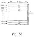
- FIG. 5C illustrates an exemplary encoding table applied to biorthogonal encoders shown in FIG. 5A
- An extended TFCI is also defined by the number of TFCI bits. That is, the extended TFCI includes 7, 8, 9 or 10 TFCI bits (hereinafter, referred to as extended TFCI bits) that represent 1 to 128, 1 to 256, 1 to 512, or 1 to 1024 different information, as stated before.
- a controller 500 divides TFCI bits into two halves. For example, for the input of 10 extended TFCI bits, the controller 500 outputs the first half of the extended TFCI as first TFCI bits (word 1) and the last half as second TFCI bits (word 2).
- the extended TFCI are basically expressed in 10 bits. Therefore, in the case where an extended TFCI bits of less than 10 bits are input, the controller 500 adds 0s to the MSB of the extended TFCI bits to represent the extended TFCI in 10 bits. Then, the controller 500 divides the 10 extended TFCI bits into word 1 and word 2. Word 1 and word 2 are fed to biorthogonal encoders 502 and 504, respectively.
- a method of separating the extended TFCI bits a 1 to a 10 into word 1 and word 2 is illustrated in FIG. 5B .
- the biorthogonal encoder 502 generates a first TFCI codeword having 16 symbols by encoding word 1 received from the controller 500.
- the biorthogonal encoder 504 generates a second TFCI codeword having 16 symbols by encoding word 2 received from the controller 500.
- the biorthogonal encoders 502 and 504 have predetermined encoding tables to output the 16-symbol TFCI codewords for the two 5-bit TFCI inputs (word 1 and word 2).
- An exemplary encoding table is illustrated in FIG. 5C . As shown in FIG.
- the encoding table lists 16 orthogonal codewords of length 16 bits c 16.1 to c 16.16 and biorthogonal codewords c 16.1 to c 16.16 that are the complements of the 16 orthogonal codewords. If the LSB of 5 TFCI bits is 1, a biorthogonal encoder (502 or 504) selects the 16 biorthogonal codewords. If the LSB is 0, the biorthogonal encoder selects the 16 orthogonal codewords. Then, the biorthogonal encoder selects one of the selected orthogonal codewords or biorthogonal codewords based on the other TFCI bits and outputs the selected codeword as the first or second TFCI codeword.
- a multiplexer 510 multiplexes the first and second TFCI codewords to a final 32-symbol TFCI codeword.
- a receiver Upon receipt of the 32-symbol TFCI codeword, a receiver decodes the TFCI codeword separately in halves (word 1 and word 2) and obtains 10 TFCI bits by combining the two decoded 5-bit TFCI halves. In this situation, a possible error even in one of the decoded 5-bit TFCI output during decoding leads to an error over the 10 TFCI bits.
- An extended TFCI codeword also should have a powerful error correction capability. To do so, the extended TFCI codeword should have the minimum distance as suggested in reference 1.
- a TFCI codeword output from the structure shown in FIG. 5A has a minimum distance of 8 because an error in at least one of word 1 and word 2 during decoding results in an error in the whole 10 TFCI bits. That is, although extended TFCI bits are encoded separately in halves, a. minimum distance between final TFCI codewords is equal to a minimum distance 8 between codeword outputs of the biorthogonal encoders 502 and 504.
- a TFCI codeword transmitted from the encoding structure shown in FIG. 5A is not optimal, which may increase an error probability of TFCI bits in the same radio channel environment.
- the receiver misjudges the data rate of received data frames and decodes the data frames with an increased error rate, thereby decreasing the efficiency of the IMT 2000 system.
- an object of the present invention to provide an apparatus and method for encoding an extended TFCI in an IMT 2000 system.
- a TFCI encoding/decoding apparatus and method in a CDMA mobile communication system In the TFCI encoding apparatus, a one-bit generator generates a sequence having the same symbols.
- a basis orthogonal sequence generator generates a plurality of basis orthogonal sequences.
- a basis mask sequence generator generates a plurality of basis mask sequences.
- An operation unit receives TFCI bits that are divided into a 1 st information part representing biorthogonal sequence conversion, a 2 nd information part representing orthogonal sequence conversion, and a 3 rd information part representing mask sequence conversion and combines an orthogonal sequence selected from the basis orthogonal sequence based on the 2 nd information, a biorthogonal sequence obtained by combining the selected orthogonal sequence with the same symbols selected based on the 1 st information part, and a mask sequence selected based on the biorthogonal code sequence and the 3 rd information part, thereby generating a TFCI sequence.
- the present invention is directed to a TFCI encoding concept of outputting final code symbols (a TFCI codeword) by adding first code symbols (a first TFCI codeword) resulting from first TFCI bits and second code symbols (a second TFCI codeword) resulting from second TFCI bits in an IMT 2000 system.
- the TFCI encoding concept is shown in FIG. 6 .
- a biorthogonal sequence and a mask sequence are given as the first TFCI codeword and the second TFCI codeword, respectively.
- TFCI bits are separated into the first TFCI bits and the second TFCI bits.
- a mask sequence generator 602 generates a predetermined mask sequence by encoding the second TFCI bits and a biorthogonal sequence generator 604 generates a predetermined biorthogonal sequence by encoding the first TFCI bits.
- An adder 610 adds the mask sequence and the biorthogonal sequence and outputs final code symbols (a TFCI codeword).
- the mask sequence generator 602 may have an encoding table that lists mask sequences for all possible second TFCI bits.
- the biorthogonal sequence generator 604 may also have an encoding table that lists biorthogonal sequences for all possible first TFCI bits.
- Walsh codes are given as orthogonal sequences by way of example in embodiments of the present invention.
- the present invention pertains to encoding and decoding of TFCI bits and use of an extended Reed Muller code in an IMT 2000 system. For this purpose, predetermined sequences are used and the sequences should have a minimum distance that ensures excellent error correction performance.
- a significant parameter that determines the performance or capability of a linear error correcting code is a minimum distance between codewords of the error correcting code.
- the Hamming weight of a codeword is the number of its symbols other than 0. If a codeword is given as "0111", its Hamming weight is 3. The smallest Hamming weight of a codeword except all "0" codeword is called a minimum weight and the minimum distance of each binary linear code is equal to the minimum weight.
- a linear error correcting code has a better error correcting performance as its minimum distance is increased. For details, see "The Theory of Error-Correcting Codes", F.J. Macwilliams and N.J.A. Sloane, North-Holland (hereinafter, referred to as reference 2).
- An extended Reed Muller code can be derived from a set of sequences each being the sum of the elements of an m-sequence and a predetermined sequence.
- the sequence set should have a large minimum distance.
- a column transposition function for making Walsh codes from m-sequences in a group which has been formed by cyclically shifting an originating m-sequence by one to 'n' times, where the 'n' is a length of the m-sequence.
- each of the m-sequences is formed by cyclically shifting the originating m-sequence by a particular number of times.
- the column transposition function is a converting function which converts the swquences in the in-sequence group to Walsh codes.
- a sequence such as a Gold sequence or a Kasami sequence which is formed by adding the originating m-sequence with another originating m-sequence.
- Another group of m-sequences is similarly formed by cyclically shifting the other originating m-sequence one to 'n' times, where 'n' is the length of the predetermined sequence.
- a reverse column transposition function is applied to the second group of m-sequences formed from the other originating m-sequence.
- the application of the reverse column transposition function to the second group of m-sequences creates another set of sequences which shall be defined as mask sequences.
- the (2 n , n+k) code represents output of a 2 n -symbol TFCI codeword for the input of (n+k) TFCI bits (input information bits).
- a Gold sequence can be expressed as the sum of two different m-sequences. To generate the (2 n , n+k) code, therefore, Gold sequences of length (2 n -1) should be produced.
- a Gold sequence is the sum of two m-sequences m 1 (t) and m 2 (t) that are generated from generator polynomials f1(x) and f2(x). Given the generator polynomials f1(x) and f2(x), the m-sequences m 1 (t) and m 2 (t) are computed using a Trace function.
- A is determined by the initial value of an m-sequence
- ⁇ is the root of the polynomial
- n is the order of the polynomial.
- FIG. 7 is a flowchart illustrating a mask sequence generating procedure for use in generating a (2 n , n+k) code from a Gold sequence set.
- m-sequences m 1 (t) and m 2 (t) are generated in Eq. 1 using the generator polynomials f1(x) and f2(x), respectively in step 710.
- a set of 31 sequences produced by cyclically shifting the m-sequence m 1 (t) 0 to 30 times are column-transposed with the use of ⁇ -1 (t)+2 derived from the reverse function of ⁇ (t) in step 730. Then, 0s are added to the start of each of the resulting column-transposed sequences to make the length of the sequence 2 n .
- a plurality of d i (t) are mask functions that can be used as 31 masks.
- each of the (2 n -1) masks can be expressed as the sum of at least two of particular n masks.
- the n masks are called basis mask sequences.
- the (2 n , n+k) code is to be generated, the total number of necessary codewords is 2 n+k for n+k input information bits (TFCI bits).
- 2 k-1 -1( (2 n+k /2 n+l )-I) masks that are not 0s are needed for generation of the (2 n , n+k) code.
- the 2 k-1 -1 masks can be expressed by the use of k-1 basis mask sequences, as stated before.
- the m-sequence m 1 (t) is cyclically shifted 0 to 2 n-1 times to generate a set of sequences in step 730 of FIG. 7 .
- linearly independent k-1 basis elements are found from the Galois elements 1, ⁇ , ..., ⁇ 2 n -2 and mask sequences corresponding to the output sequences of a Trace function with the k-1 basis elements as an initial sequence become basis mask sequences.
- a linear independence condition is expressed as ⁇ 1 , ..., ⁇ k-1 : linearly independent ⁇ c 1 ⁇ ⁇ 1 + c 2 ⁇ ⁇ 2 + ... + c k - 1 ⁇ ⁇ k - 1 ⁇ 0 , ⁇ c 1 , c 2 , ... , c k - 1
- a Gold sequence is expressed as the sum of different predetermined m-sequences. Therefore, a Gold sequence of length 31 should be generated first in order to generate the intended (32, 10) code.
- the Gold sequence is the sum of two m-sequences generated respectively from polynomials x 5 +x 2 +1 and x 5 + x 4 + x+1.
- FIG. 7 illustrates the mask function generating procedure to generate the (32, 10) code.
- m-sequences m 1 (t) and m 2 (t) are generated in Eq. 1 using the generator polynomials f1(x) and f2(x), respectively in step 710.
- a set of 31 sequences produced by cyclically shifting the m-sequence m 1 (t) 0 to 30 times are column-transposed with the use of ⁇ -1 (t)+2 derived from the reverse function of ⁇ (t) in step 730. Then, 0s are added to the start of each of the resulting sequence-transposed sequences to make the length of the sequence 31.
- 31 d i (t) of length 32 are generated.
- the sequences set generated in step 730 can be expressed as d i t
- a plurality of d i (t) obtained from Eq. 7 can be used as 31 mask sequences.
- each of the 31 masks can be expressed as a sum of 5 particular masks. These 5 masks are basis mask sequences.
- 15 masks are needed to generate the (32, 10) code.
- the 15 masks can be expressed as combinations of 4 basis mask sequences.
- 4 linearly independent basis elements are found from the Galois elements 1, ⁇ , ..., ⁇ 2n-2 and mask sequences corresponding to the output sequences of a Trace function with the 4 basis elements as an initial sequence becoming basis mask sequences.
- a linear independence condition is expressed as ⁇ , ⁇ , ⁇ , ⁇ : linearly independent ⁇ c 1 ⁇ ⁇ + c 2 ⁇ ⁇ + c 3 ⁇ ⁇ , + c 4 ⁇ ⁇ ⁇ 0 , ⁇ c 1 , c 2 , c 3 , c 4
- ⁇ , ⁇ 2 , ⁇ 3 in the Galois GF(2 5 ) are polynomial sub-bases that are well known as four linearly independent elements.
- four basis mask sequences M1, M2, M4, and M8 are achieved.
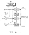
- FIGs. 8 and 9 are block diagrams of TFCI encoding and decoding apparatuses in an IMT 2000 system according to an embodiment of the present invention.
- a one-bit generator 800 continuously generates a predetermined code bit. That is, since the present invention deals with biorthogonal sequences, necessary bits are generated to make a biorthogonal sequence out of an orthogonal sequence.
- the one-bit generator 800 generates bits having 1s to inverse an orthogonal sequence (i.e., a Walsh code) generated from a basis Walsh code generator 810 and thus generate a biorthogonal sequence.
- the basis Walsh code generator 810 generates basis Walsh codes of a predetermined length.
- the basis Walsh codes refer to Walsh codes from which all intended Walsh codes can be produced through arbitrary addition. For example, when Walsh codes of length 32 are used, the basis Walsh codes are 1 st , 2 nd , 4 th , 8 th , and 16 th Walsh codes W1, W2, W4, W8, and W16, wherein:
- a basis mask sequence generator 820 generates a basis mask sequence of a predetermined length.
- a basis mask sequence generating method has already been described before and its details will not be described. If a mask sequence of length 32 is used, basis mask sequences are 1 st , 2 nd , 4 th , and 8 th mask sequences M1, M2, M4, M8, wherein:
- the multiplier 840 multiplies 1s output from the one-bit generator 800 by the input information bit a0 on a symbol basis.
- the multiplier 841 multiplies the basis Walsh code W1 received from the basis Walsh code generator 810 by the input information bit a1.
- the multiplier 842 multiplies the basis Walsh code W2 received from the basis Walsh code generator 810 by the input information bit a2.
- the multiplier 843 multiplies the basis Walsh code W4 received from the basis Walsh code generator 810 by the input information bit a3.
- the multiplier 844 multiplies the basis Walsh code W8 received from the basis Walsh code generator 810 by the input information bit a4.
- the multiplier 845 multiplies the basis Walsh code W16 received from the basis Walsh code generator 810 by the input information bit a5.
- the multipliers 841 to 845 multiply the received basis Walsh codes W1, W2, W4, W8, and W16 by their corresponding input information bits symbol by symbol.
- the multiplier 846 multiplies the basis mask sequence M1 by the input information bit a6.
- the multiplier 847 multiplies the basis mask sequence M2 by the input information bit a7.
- the multiplier 848 multiplies the basis mask sequence M4 by the input information bit a8.
- the multiplier 849 multiplies the basis mask sequence M8 by the input information bit a9.
- the multipliers 846 to 849 multiply the received basis mask sequences M1, M2, M4, and M8 by their corresponding input information bits symbol by symbol.
- An adder 860 adds the encoded input information bits received from the multipliers 840 to 849 and outputs final code symbols of length 32 bits (a TFCI codeword).
- the length of the final code symbols (TFCI codeword) is determined by the lengths of the basis Walsh codes generated from the basis Walsh code generator 810 and the basis mask sequences generated from the basis mask sequence generator 820.
- the multiplier 840 multiplies 0 as a0 by 1s received from the one-bit generator 800 and generates 32 code symbols being all "0s”.
- the multiplier 841 multiplies 1 as a1 by W1 received from the basis Walsh code generator 810 and generates code symbols "010101010101010101010101”.
- the multiplier 842 multiplies 1 as a2 by W2 received from the basis Walsh code generator 810 and generates code symbols "0011001100110011001100110011001100110011”.
- the multiplier 843 multiplies 1 as a3 by W4 received from the basis Walsh code generator 810 and generates code symbols "00001111000011110000111100001111".
- the multiplier 844 multiplies 0 as a4 by W8 received from the basis Walsh code generator 810 and generates 32 code symbols being all "0s”.
- the multiplier 845 multiplies 1 as a5 by W16 received from the basis Walsh code generator 810 and generates "00000000000000001111111111111111111111111”.
- the multiplier 846 multiplies 1 as a6 by M1 received from the basis mask sequence generator 820 and generates "00101000011000111111000001110111".
- the multiplier 847 multiplies 0 as a7 by M2 received from the basis mask sequence generator 820 and generates 32 code symbols being all 0s.
- the multiplier 848 multiplies 0 as a8 by M4 received from the basis mask sequence generator 820 and generates 32 code symbols being all 0s.
- the multiplier 849 multiplies 0 as a9 by M8 received from the basis mask sequence generator 820 and generates 32 code symbols being all 0s.
- the adder 860 adds the code symbols received from the multipliers 840 to 849 and outputs final code symbols "01000001000010100110011011100001".
- the final code symbols can be achieved by adding the basis Walsh codes W1, W2, W4 and W16 corresponding to the information bits 1s to the basis mask sequence M1 symbol by symbol.
- FIG. 11 is a flowchart illustrating an embodiment of a TFCI encoding procedure in an IMT 2000 system according to the present invention.
- 10 input information bits i.e., TFCI bits
- variables sum and j are set to an initial value 0 in step 1100.
- the variable sum indicates final code symbols
- j indicates the count number of final code symbols output after symbol-basis addition.
- step 1110 If j is not 32 in step 1110, which implies that the input information bits are not encoded completely with respect to all symbols of the Walsh codes, the mask sequences, j th symbols W1(j), W2(j), W4(j), W8(j), and W16(j) of the basis Walsh codes W1, W2, W4, W8, and W16 and j th symbols M1(j), M2(j), M4(j), and M8(j) of the basis mask sequences M1, M2, M4, and M8 are received in step 1120. Then, the received symbols are multiplied by the input information bits on a symbol basis and the symbol products are summed in step 1130. The sum becomes the variable sum.
- the input information bits are multiplied by corresponding symbols of the basis Walsh codes and basis mask sequences, symbol products are summed, and the sum becomes an intended code symbol.
- step 1140 sum indicating the achieved j th code symbol, is output. j is increased by 1 in step 1150 and then the procedure returns to step 1110. Meanwhile, if j is 32 in step 1110, the encoding procedure ends.
- the encoding apparatus of FIG. 8 can support extended TFCIs as well as basic TFCIs.
- Encoders for supporting an extended TFCI include a (32, 10) encoder, a (32, 9) encoder, and a (32, 7) encoder.
- the (32, 10) encoder For the input of 10 input information bits, the (32, 10) encoder outputs a combination of 32 Walsh codes of length 32, 32 bi-orthogonal codes inverted from the Walsh codes, and 15 mask sequences.
- the 32 Walsh codes can be generated from combinations of 5 basis Walsh codes.
- the 32 bi-orthogonal codes can be obtained by adding 1 to the 32 symbols of each Walsh code. This results has the same effect as multiplication of -1 by the 32 Walsh codes viewed as real numbers.
- the 15 mask sequences can be achieved through combinations of 5 basis mask sequences. Therefore, a total of 1024 codewords can be produced from the (32, 10) encoder.
- the (32, 9) encoder receives 9 input information bits and outputs a combination of 32 Walsh codes of length 32, 32 bi-orthogonal codes inverted from the Walsh codes, and 4 mask sequences.
- the 4 mask sequences are obtained by combing two of 4 basis mask sequences.
- the (32, 7) encoder receives 7 input information bits and outputs a combination of 32 Walsh codes of length among the 1024 codewords, 32 bi-orthogonal codes inverted from the Walsh codes, and one of 4 basis mask sequences.
- the above encoders for providing extended TFCIs have a minimum distance 12 and can be implemented by blocking input and output of at least of the 4 basis mask sequences generated from the basis mask sequences 820.
- the (32, 9) encoder can be implemented by blocking input and output of one of the four basis mask sequences generated from the basis mask sequence generator 820 shown in FIG. 8 .
- the (32, 8) encoder can be implemented by blocking input and output of two of the basis mask sequences generated from the basis mask sequence generator 820.
- the (32, 7) encoder can be implemented by blocking input and output of three of the basis mask sequences generated from the basis mask sequence generator 820.
- the encoding apparatus according to the embodiment of the present invention can encode flexibly according to the number of input information bits, that is, the number of TFCI bits to be transmitted and maximizes a minimum distance that determined the performance of the encoding apparatus.
- Codewords in the above encoding apparatus are sequences obtained by combining 32 Walsh codes of length 32, 32 bi-orthogonal codes resulting from adding 1s to the Walsh codes, and 15 mask sequences of length 15.
- the structure of the codewords is shown in FIG. 13 .
- An input signal r(t) is applied to 15 multipliers 902 to 906 and a correlation calculator 920.
- the input signal r(t) was encoded with a predetermined Walsh code and a predetermined mask sequence in a transmitter.
- a mask sequence generator 910 generates all possible 15 mask sequences M1 to M15.
- the multipliers 902 to 906 multiply the mask sequences received from the mask sequence generator 910 by the input signal r(t).
- the multiplier 902 multiplies the input signal r(t) by the mask sequence M1 received from the mask sequence generator 910.
- the multiplier 904 multiplies the input signal r(t) by the mask sequence M2 received from the mask sequence generator 910.
- the multiplier 906 multiplies the input signal r(t) by the mask sequence M15 received from the mask sequence generator 910. If the transmitter encoded TFCI bits with the predetermined mask sequence, one of the outputs of the multipliers 902 to 906 is free of the mask sequence, which means the mask sequence has no effect on the correlations calculated by one of the correlation calculators. For example, if the transmitter used the mask sequence M2 for encoding the TFCI bits, the output of the multiplier 904 that multiplies the mask sequence M2 by the input signal r(t) is free of the mask sequence.
- the mask sequence-free signal is TFCI bits encoded with the predetermined Walsh code.
- Correlation calculators 920 to 926 calculate the correlations of the input signal r(t) and the outputs of the multipliers 902 to 906 to 64 bi-orthogonal codes.
- the 64 bi-orthogonal codes have been defined before.
- the correlation calculator 920 calculates the correlation values of the input signal r(t) to the 64 bi-orthogonal codes of length 32, selects the maximum correlation value from the 64 correlations, and outputs the selected correlation value, a bi-orthogonal code index corresponding to the selected correlation value, and its unique index "0000" to a correlation comparator 940.
- the correlation calculator 922 calculates the correlation values of the output of the multiplier 902 to the 64 bi-orthogonal codes, selects the maximum value of the 64 correlations, and outputs the selected correlation value, a bi-orthogonal code index corresponding to the selected correlation, and its unique index "0001" to the correlation comparator 940.
- the correlation calculator 924 calculates the correlation values of the output of the multiplier 904 to the 64 bi-orthogonal codes, selects the maximum of the 64 correlation values, and outputs the selected correlation value, a bi-orthogonal code index corresponding to the selected correlation value, and its unique index "0010" to the correlation comparator 940.
- Other correlation calculators (not shown) calculate the correlation values of the outputs of the correspondent multipliers to the 64 bi-orthogonal codes and operate similar to the above described correlation calculators, respectively.
- the correlation calculator 926 calculates the correlation values of the output of the multiplier 906 to the 64 bi-orthogonal codes, selects the maximum value of the 64 correlations, and outputs the selected correlation value, a bi-orthogonal code index corresponding to the selected correlation value, and its unique index "1111" to the correlation comparator 940.
- the unique indexes of the correlation calculators 920 to 926 are the same as the indexes of the mask sequences multiplied by the input signal r(t) in the multipliers 902 to 906.
- Table 2 lists the 15 mask indexes multiplied in the multipliers and a mask index assigned to the case that no mask sequence is used, by way of example. (Table 2) mask sequence mask sequence index mask sequence mask sequence index not used 0000 M8 1000 M1 0001 M9 1001 M2 0010 M10 1010 M3 0011 M11 1011 M4 0101 M12 1100 M5 0101 M13 1101 M6 0110 M14 1110 M7 0111 M15 1111
- the correlation calculator 922 which receives the signal which is the product of the input signal r(t) and the mask sequence M1, outputs "0001" as its index.
- the correlation calculator 926 which receives the signal which is the product of the input signal r(t) and the mask sequence M15, outputs "1111” as its index.
- the correlation calculator 920 which receives only the input signal r(t), outputs "0000" as its index.
- the bi-orthogonal code indexes are expressed in a binary code. For example, if the correlation to W 4 which is the complement of W4is the largest correlation value, a corresponding bi-orthogonal code index (a0 to a9) is "001001".
- the correlation comparator 940 compares the 16 maximum correlation values received from the correlation calculators 920 to 926, selects the highest correlation value from the 16 received maximum correlation values, and outputs TFCI bits based on the bi-orthogonal code index and the mask sequence index(the unique index) received from the correlation calculator that corresponds to the highest correlation value.
- the TFCI bits can be determined by combining the bi-orthogonal code index and the mask sequence index. For example, if the mask sequence index is that of M4(0100) and the bi-orthogonal code index is that of W 4 (001001), the TFCI bits(a9 to a0) are "the M4 index(0100) + the W 4 index(001001)". That is, the TFCI bits(a9 to a0) are "0100001001"
- the transmitter transmitted code symbols corresponding to TFCI bits (a0 to a9) "1011000010"
- the receiver can determine that the input signal r(t) is encoded with the mask sequence M4 by multiplying the input signal r(t) by all the mask sequences and that the input signal r(t) is encoded with W 6 by calculating the correlations of the input signal r(t) to all the bi-orthogonal codes.
- the fifth correlation calculator(not shown) will output the largest correlation value, the index of W 6 (101100) and its unique index(0010).
- the receiver outputs the decoded TFCI bits(a0 to a9) "1011000010” by adding the index of W 6 "101100” and the M4 index "0010".
- the input signal r(t) is processed in parallel according to the number of mask sequences. It can be further contemplated that the input signal r(t) is sequentially multiplied by the mask sequences and the correlations of the products are sequentially calculated in another embodiment of the decoding apparatus.
- FIG. 17 illustrates another embodiment of the decoding apparatus.
- a memory 1720 stores an input 32-symbol signal r(t).
- a mask sequence generator 1710 generates 16 mask sequences that were used in the transmitter and outputs them sequentially.
- a multiplier 1730 multiplies one of the 16 mask sequences received from the mask sequence generator 1710 by the input signal r(t) received from the memory 1720.
- a correlation calculator 1740 calculates the output of the multiplier 1730 to 64 biorthogonal codes bi-orthogonalof length 32 and outputs the maximum correlation value and the index of a biorthogonal code corresponding to the largest correlation value to a correlation comparator 1750.
- the correlation comparator 1750 stores the maximum correlation value and the biorthogonal code index received from the correlation calculator 1740, and the index of the mask sequence received from the mask sequence generator 1710.
- the memory 1720 Upon completion of above processing with the mask sequence, the memory 1720 outputs the stored input signal r(t) to the multiplier 1730.
- the multiplier 1730 multiplies the input signal r(t) by one of the other mask sequences.
- the correlation calculator 1740 calculates correlation of the the output of the multiplier 1730 to the 64 biorthogonal codes of length 32 and outputs the maximum correlation value and the index of a biorthogonal code corresponding to the maximum correlation value.
- the correlation comparator 1750 stores the maximum correlation value, the biorthogonal code index corresponding to the maximum correlation value, and the mask sequence index received from the mask sequence generator 1710.
- the above procedure is performed on all of the 16 mask sequences generated from the mask sequence generator 1710. Then, 16 maximum correlation values the indexes of biorthogonal codes corresponding to the maximum correlation value are stored in the correlation comparator 1750.
- the correlation comparator 1750 compares the stored 16 correlation values and selects the one with the highest correlation and outputs TFCI bits by combining the indexes of the biorthogonal code and mask sequence index corresponding to the selected maximum correlation value.
- the input signal r(t) is deleted from the memory 1720 and the next input signal r(t+1) is stored.
- the correlation comparator 1750 compares the 16 maximum correlation values at one time in the decoding apparatus of FIG. 17
- real-time correlation value comparison can be contemplated. That is, the first input maximum correlation value is compared with the next input maximum correlation value and the larger of the two correlation values and a mask sequence index and a biorthogonal code index corresponding to the correlation are stored. Then, the thirdly input maximum correlation is compared with the stored correlation and the larger of the two correlations and a mask sequence index and a biorthogonal code index corresponding to the selected correlation are stored. This comparision/operation occurs 15 times which is the number of mask sequences generated from the mask sequence generator 1710. Upon completion of all the operations, the correlation comparator 1710output the finally stored biorthogonal index(a0 to a6) and mask sequence index(a7 to a9) and outputs the added bits as TFCI bits.
- FIG. 10 is a flowchart illustrating the operation of the correlation comparator 940 shown in FIG. 9 .
- the correlation comparator 940 stores the sixteen maximum correlation values, selects a highest correlation value out of the 16 maximum correlation values and output TFCI bits based on the indexes of a bi-orthogonal code and a mask sequence corresponding to the selected highest correlation value.
- the sixteen correlation values are compared, and TFCI bits are outputted based on the indexes of a bi-orthogonal code and a mask sequence corresponding to the highest correlation value.
- a maximum correlation index i is set to 1 and the indices of a maximum correlation value, a biorthogonal code, and a mask sequence to be checked are set to 0s in step 1000.
- the correlation comparator 940 receives a 1 st maximum correlation value, a 1 st bi-orthogonal code index, and a 1 st mask sequence index from the correlation calculator 920.
- the correlation comparator 940 compares the 1 st maximum correlation with an the previous maximum correlation value in step 1020. If the 1 st maximum correlation is greater than the previous maximum correlation, the procedure goes to step 1030. If the 1 st maximum correlation is equal to or smaller than the previous maximum correlation, the procedure goes to step 1040.
- the correlation comparator 940 designates the 1 st maximum correlation as a final maximum correlation and stores the 1 st bi-orthogonal code and mask sequence indexes as final bi-orthogonal code and mask sequence indexes.
- the correlation comparator 940 compares the index i with the number 16 of the correlation calculators to determine whether all 16 maximum correlations are completely compared. If i is not 16, the index i is increased by 1 in step 1060 and the procedure returns to step 1010. Then, the above procedure is repeated.
- the correlation comparator 940 outputs the indexes of the bi-orthogonal code and the mask sequence that correspond to the final maximum correlation as decoded bits.
- the bi-orthogonal code index and the mask sequence index corresponding to the decoded bits are those corresponding to the final maximum correlation among the 16 maximum correlation values received from the 16 correlation calculators.
- the (32, 10) TFCI encoder that outputs a 32-symbol TFCI codeword in view of 16 slots has been described in the first embodiment of the present invention. Recently, the IMT-2000 standard specification dictates having 15 slots in one frame. Therefore, the second embodiment of the present invention is directed to a (30, 10) TFCI encoder that outputs a 30-symbol TFCI codeword in view of 15 slots. Therefore, the second embodiment of the present invention suggests an encoding apparatus and method for outputting 30 code symbols by puncturing two symbols of 32 coded symbols(codeword) as generated from the (32, 10) TFCI encoder.
- the encoding apparatuses according to the first and second embodiments of the present invention are the same in configuration except that sequences output from a one-bit generator, a basis Walsh code generator, and a basis mask sequence generator.
- the encoder apparatus outputs coded symbols of length 30 with symbol #0(1 st symbol) and symbol #16(17 st symbol) are punctured in the encoding apparatus of the second embodiment.
- 10 input information bits a0 to a9 are applied to the input of the 840 to 849.
- the one-bit generator 800 outputs symbols 1s(length 32) to the multiplier 840.
- the multiplier 840 multiplies the input information bit a0 by each 32 symbol received from the one-bit generator 800.
- the basis Walsh code generator 810 simultaneously generates basis Walsh codes W1, W2, W4, W8, and W16 of length 32.
- the multiplier 841 multiplies the input information bit a1 by the basisWalsh code W1 "010101010101010101010101".
- the multiplier 842 multiplies the input information bit a2 by the basis Walsh code W2 "00110011001100110011001100110011”.
- the multiplier 843 multiplies the input information bit a3 by the basis Walsh code W4 "00001111000011110000111100001111".
- the multiplier 844 multiplies the input information bit a4 by the basis Walsh code W8 "00000000111111110000000011111111”.
- the multiplier 845 multiplies the input information bit a5 by the basis Walsh code W16 "00000000000000001111111111111111”.
- the basis mask sequence generator 820 simultaneously generates basis mask sequences M1, M2, M4, and M8 of length 32.
- the multiplier 846 multiplies the input information bit a6 by the basis mask sequence M1 "00101000011000111111000001110111".
- the multiplier 847 multiplies the input information bit a7 by the basis mask sequence M2 "00000001110011010110110111000111".
- the multiplier 848 multiplies the input information bit a8 by the basis mask sequence M4 "00001010111110010001101100101011".
- the multiplier 849 multiplies the input information bit a9 by the basis mask sequence M8. "00011100001101110010111101010001".
- the multipliers 840 to 849 function like switches that control the output of or the generation of the bits from the one-bit generator, each of the basis walsh codes and each of the basis mask sequences.
- the adder 860 sums the outputs of the multipliers 840 to 849 symbol by symbol and outputs 32 coded symbols (i.e., a TFCI codeword). Out of the 32 coded symbols, two symbols will be punctured at predetermined positions (i.e. the symbol #0(the first symbol) and symbol #16(the 17 th symbol) of the adder 860 output are punctured). The remaining 30 symbols will become the 30 TFCI symbols. It will be easy to modify the second embodiment of present invention. For example, the one-bit generator 800, basis walsh generator 810, basis mask sequence generator 820 can generate 30 symbols which excludes the #0 and #16 symbols. The adder 860 then adds the output of the one-bit generator 800, basis walsh generator 810 and basis mask sequence generator 820 bit by bit and output 30 encoded symbols as TFCI symbols.
- FIG. 12 is a encoding method for the second embodiment of present invention.
- the flowchart illustrating the steps of the encoding apparatus according to the second embodiment of the present invention when the number of slots is 15.
- step 1210 it is determined whether j is 30. If j is not 30 in step 1210, the j th symbols W1(j), W2(j), W4(j), W8(j), and W16(j) of the basis Walsh codes W1, W2, W4, W8, and W16 (each having two punctured bits) and the j th symbols M1(j), M2(j), M4(j), and M8(j) of the basis mask sequences M1, M2, M4, and M8 (each having two punctured bits) are received in step 1220.
- step 1240 sum indicating the achieved j th code symbol is output. j is increased by 1 in step 1250 and then the procedure returns to step 1210. Meanwhile, if j is 30 in step 1210, the encoding procedure ends.
- the (30, 10) encoder outputs 1024 codewords equivalent to the codewords of the (32, 10) encoder with symbols #0 and #16 punctured. Therefore, the total number of information can be expressed is 1024.
- the output of a (30, 9) encoder is combinations of 32 Walsh codes of length 30 obtained by puncturing symbols #0 and #16 of each of 32 Walsh codes of length 32, 32 bi-orthogonal codes obtained by adding 1 to each symbol of the punctured Walsh codes (by multiplying -1 to each symbol in the case of a real number), and 8 mask sequences obtained by combining any three of the four punctured basis mask sequences.
- the output of a (30, 8) encoder is combinations of 32 Walsh codes of length 30 obtained by puncturing #0 and #16 symbols from each of 32 Walsh codes having a length 32 symbols, 32 bi-orthogonal codes obtained by adding 1 to each symbol of the punctured Walsh codes (by multiplying -1 to each symbol in the case of a real number), and 4 mask sequences obtained by combining any two of the four punctured basis mask sequences.
- the output of a (30, 7) encoder is combinations of 32 Walsh codes of length 30 obtained by puncturing #0 and #16 symbols from each of 32 Walsh codes having a length 32 symbols, 32 bi-orthogonal codes obtained by adding 1 to each symbol of the punctured Walsh codes (by multiplying -1 to each symbol in the case of a real number), and one of the four punctured basis mask sequences.
- All the above encoders for providing an extended TFCI have a minimum distance of 10.
- the (30, 9), (30, 8), and (30, 7) encoders can be implemented by blocking input and output of at least one of the four basis mask sequences generated from the basis mask sequence generator 820 shown in FIG. 8 .
- the above encoders flexibly encode TFCI bits according to the number of the TFCI bits and has a maximized minimum distance that determines encoding performance.
- a decoding apparatus is the same in configuration and operation as the decoding apparatus of the first embodiment except for different signal lengths of the encoded symbols. That is, after (32,10) encoding, two symbols out of the 32 encoded symbols are punctured, or basis walsh codes with two punctured symbols and basis mask sequences with two punctured symbols are used for generating the 30 encoded symbols. Therefore, except for the received signal r(t) which includes a signal of 30 encoded symbols and insertion of dummy signals at the punctured positions, all decoding operations are equal to the description of the first embodiment of present invention.
- this second embodiment of decoding also can be implemented by a single multiplier for multiplying the masks with r(t) and a single correlation calculator for calculating correlation values of bi-orthogonal codes.
- the third embodiment of the present invention provides an encoding apparatus for blocking the output of a one-bit generator in the (30, 7), (30, 8), (30, 9) or (30, 10) (hereinafter we express (30, 7-10))encoder of the second embodiment and generating another mask sequence instead in order to set a minimum distance to 11.
- the encoders refer to an encoder that outputs a 30-symbol TFCI codeword for the input of 7, 8, 9 or 10 TFCI bits.
- FIG. 14 is a block diagram of a third embodiment of the encoding apparatus for encoding a TFCI in the IMT 2000 system.
- a (30, 7-10) encoder is configured to have a minimum distance of 11.
- the encoding apparatus of the third embodiment is similar in structure to that of the second embodiment except that a mask sequence generator 1480 for generating a basis mask sequence M16 and a switch 1470 for switching the mask sequence generator 1480 and a one-bit generator 1400 to a multiplier 1440 are further provided to the encoding apparatus according to the third embodiment of the present invention.
- the two bit punctured basis mask sequences M1, M2, M4, M8, and M16 as used in FIG. 14 are identical to each other.
- the switch 1470 switches the one-bit generator 1400 to the multiplier 1440 and blocks all the basis mask sequences generated from a basis mask sequence generator 1480.
- the multiplier 1440 multiplies the symbols from the one-bit generator 1400 with the input information bit a0, symbol by symbol.
- the switch 1470 switches the mask sequence generator 1480 to the multiplier 1440 and selectively uses four basis mask sequences generated from a basis mask sequence generator 1420.
- 31 mask sequences M1 to M31 can be generated by combining 5 basis mask sequences.
- the switch 1470 switches the mask sequence generator 1480 to the multiplier 1440 to use the (30, 7-10) encoder, whereas the switch 1470 switches the one-bit generator 1400 to the multiplier 1440 to use the (30, 6) encoder.
- the (30, 6) encoder For the input of 6 information bits, the (30, 6) encoder outputs a 30-symbol codeword by combining 32 Walsh codes of length 30 with 32 bi-orthogonal codes obtained by inverting the Walsh codes by the use of the one-bit generator 1400.
- the (30, 10) encoder For the input of 10 information bits, the (30, 10) encoder outputs a 30-symbol codeword by combining 32 Walsh codes of length 30 and 32 mask sequences generated using five basis mask sequences.
- the five basis mask sequences are M1, M2, M4, M8, and M16, as stated above and the basis mask sequence M16 is output from the mask sequence generator 1480 that is added for the encoding apparatus according to the third embodiment of the present invention.
- 1024 codewords can be achieved from the (30, 10) encoder.
- the (30, 9) encoder outputs a 30-symbol codeword by combining 32 Walsh codes and 16 mask sequences, for the input of 9 information bits.
- the 16 mask sequences are achieved by combining four of five basis mask sequences.
- the (30, 8) encoder outputs a 30-symbol codeword by combining 32 Walsh codes and 8 mask sequences, for the input of 8 information bits.
- the 8 mask sequences are obtained by combining three of five basis mask sequences.
- the (30, 7) encoder outputs a 30-symbol codeword by combining 32 Walsh codes of length 30 and four mask sequences.
- the four mask sequences are obtained by combining two of five basis mask sequences.
- All the above (30, 7-10) encoders have a minimum distance of 11 to provide extended TFCIs.
- the (32, 7-10) encoders can be implemented by controlling use of at least one of the five basis mask sequences generated from the basis mask sequence generator 1420 and the mask sequence generator 1480 shown in FIG. 14 .
- FIG. 16 is a flowchart illustrating a third embodiment of the TFCI encoding procedure in the IMT 2000 system according to the present invention.
- step 1600 10 information bits (TFCI bits) a0 to a9 are received and variables sum and j are set to initial values 0s in step 1600.
- the variable sum indicates a final code symbol output after symbol-basis addition and the variable j indicates the count number of final code symbols output after the symbol-basis addition.
- the purpose of performing step 1610 is to judge whether the input information bits are encoded with respect to the 30 symbols of each Walsh code and the 30 symbols of each mask sequence.
- step 1610 If j is not 30 in step 1610, which implies that encoding is not completed with respect to all the symbols of the Walsh codes and mask sequences, the j th symbols W1(j), W2(j), W4(j), W8(j), and W16(j) of the basis Walsh codes W1, W2, W4, W8, and W16 and the j h symbols M1(j), M2(j), M4(j), M8(j), and M16(j) of the basis mask sequences M1, M2, M4, M8, and M16 are received in step 1620.
- step 1630 the input information bits are multiplied by the received symbols symbol by symbol and the symbol products are summed.
- an intended code symbol is obtained by multiplying each input information bit by the symbols of a corresponding basis Walsh code or basis mask sequence and summing the products.
- step 1640 sum indicating the achieved j th code symbol is output. j is increased by 1 in step 1650 and then the procedure returns to step 1610. Meanwhile, if j is 30 in step 1610, the encoding procedure ends.
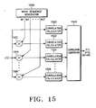
- An input signal r(t) which includes the 30 encoded symbols signal transmitted by a transmitter and two dummy symbols which have been inserted at the positions that have been punctured by the encoder is applied to 31 multipliers 1502 to 1506 and a correlation calculator 1520.
- a mask sequence generator 1500 generates all possible 31 mask sequences of length 32 M1 to M31.
- the multipliers 1502 to 1506 multiply the mask sequences received from the mask sequence generator 1500 by the input signal r(t).
- a transmitter encoded TFCI bits with a predetermined mask sequence one of the outputs of the multipliers 1502 to 1506 is free of the mask sequence, which means the mask sequence has no effect on the following correlation calculator.
- the output of the multiplier 1506 that multiplies the mask sequence M31 by the input signal r(t) is free of the mask sequence.
- the input signal r(t) itself applied to a correlation calculator 1520 is a mask sequence-free signal.
- Each correlation calculators 1520 to 1526 calculates the correlation values of the outputs of the multipliers 1502 to 1506 with 64 bi-orthogonal codes of length 32, determines maximum correlation value among the 64-correlation sets, and outputs the determined maximum correlation values, the indexes of each bi-orthogonal codescorresponding to the determined maximum correlation values, and each indexe of the mask sequences to a correlation comparator 1540,respectively.
- the correlation comparator 1540 compares the 32 maximum correlation values received from the correlation calculators 1520 to 1526 and determines the largest of the maximum correlation values as a final maximum correlation. Then, the correlation comparator 1540 outputs the decoded TFCI bits transmitted by the transmitter on the basis of the indexes of the bi-orthogonal code and mask sequence corresponding to the final maximum correlation value.
- the third embodiment of present invention can be also implemented by a single multiplier for multiplying the masks with r(t) and a single correlation calculator for calculating correlation values of bi-orthogonal codes.
- the present invention provides an apparatus and method for encoding and decoding a basic TFCI and an extended TFCI variably so that hardware is simplified. Another advantage is that support of both basic TFCI and extended TFCI error correcting coding schemes increases service stability. Furthermore, a minimum distance, a factor that determined the performance of an encoding apparatus, is large enough to satisfy the requirement of an IMT 2000 system, thereby ensuing excellent performance.
Abstract
Description
- The present invention relates generally to an information transmitting apparatus and method in an IMT 2000 system, and in particular, to an apparatus and method for transmitting a transport format combination indicator (TFCI).
- A CDMA mobile communication system (hereinafter, referred to as an IMT 2000 system) generally transmits frames that provide a voice service, an image service, a character service on a physical channel such as a dedicated physical data channel (DPDCH) at a fixed or variable data rate. In the case where the data frames which include that sort of services are transmitted at a fixed data rate, there is no need to inform a receiver of the spreading rate of each data frame. On the other hand, if the data frames are transmitted at a variable data rate, which implies that each data frame has a different data rate, a transmitter should inform the receiver of the spreading rate of each data frame determined by its data rate. A data rate is proportional to a data transmission rate and the data transmission rate is inversely proportional to a spreading rate in a general IMT 2000 system.
- For transmission of data frames at a variable data rate, a TFCI field of a DPCCH informs a receiver of the data rate of the current service frame. The TFCI field includes a TFCI indicating a lot of information including the data rate of a service frame. The TFCI is information that helps a voice or data service to reliably be provided.
-
FIGs. 1A to 1D illustrate examples of applications of a TFCI.FIG. 1A illustrates application of the TFCI to an uplink DPDCH and an uplink dedicated physical control channel (DPCCH).FIG. 1B illustrates application of the TFCI to a random access channel (RACH).FIG. 1C illustrates application of the TFCI to a downlink DPDCH and a downlink DPCCH.FIG. 1D illustrates application of the TFCI to a secondary common control physical channel (SCCPCH). - Referring to
FIGs. 1A to 1D , one frame is comprised of 16 slots and each slot has a TFCI field. Thus, one frame includes 16 TFCI fields. A TFCI field includes NTFCI bits and a TFCI generally has 32 bits in a frame. To transmit the 32-bit TFCI in one frame, 2 TFCI bits can be assigned to each of the 16 slots (Tslot = 0.625ms). -
FIG. 2 is a block diagram of a base station transmitter in a general IMT 2000 system. - Referring to
FIG. 2 ,multipliers multiplexer 212inserts 32 bit TFCIcode symbols(TFCI codeword) received from themultiplier 221 into the TFCI fields as shown inFIG 1C . Amultiplexer 242inserts 32 bit TFCI code symbols received from themultiplier 241 into the TFCI fields. Amultiplexer 252inserts 32 bit TFCI code symbols received from themultiplier 242 into the TFCI fields. Insertion of TFCI code symbols into TFCI fields is shown inFIGs. 1A to 1D . The 32 code symbols are obtained by encoding TFCI bits(information bits) that define the data rate of a data signal on a corresponding data channel. 1st, 2nd, and 3rd serial to parallel converters (S/Ps) 213, 233, and 234 separate the outputs of themultiplexers Multipliers Ps first summer 215 sums the outputs of themultipliers second summer 223 sums the outputs of themultipliers phase shifter 224 shifts the phase of the Q channel signal received from thesecond summer 223 by 90°. Asummer 216 adds the outputs of thefirst summer 215 and thephase shifter 224 and generates a complex signal I+jQ. Amultiplier 217 scrambles the complex signal with a complex PN sequence Cscramb assigned to the base station. A signal processor(S/P) 218 separates the scrambled signal into an I channel and a Q channel. Low-pass filters (LPFs) 219 and 225 limits the bandwidths of the I channel and Q channel signals received from the S/P 218 by low-pass-filtering.Multipliers LPFs LPFs summer 227 sums the RF I channel and Q channel signals. -
FIG. 3 is a block diagram of a mobile station transmitter in the general IMT 2000 system. - Referring to
FIG. 3 ,multipliers input signal 4 includes pilots and TPCs of a DPCCH.TFCI information bits are encoded into 32 bit TFCI code symbols by aTFCI encoder 309. Amultiplier 310 inserts a 32 bit TFCI code symbols into thesignal 4 as shown inFIG. 1A . Amultiplier 325 multiplies multiplies a DPCCH signal which include TFCI code symbol received from themultiplier 310 by a channelization code Cch4. The channelization codes Cch1 to Cch4 are orthogonal codes. The 32 TFCI code symbols are obtained by encoding TFCI information bits that define the data rate of the DPDCH signals.Multipliers multipliers first summer 313 generates an I channel signal by adding the outputs of themultipliers second summer 327 generates a Q channel signal by adding the outputs of themultipliers phase shifter 328 shifts the phase of the Q channel signal received from thesecond summer 327 by 90°. Asummer 314 adds the outputs of thefirst summer 313 and thephase shifter 328 and generates a complex signal I+jQ. Amultiplier 315 scrambles the complex signal with a PN sequence Cscramb assigned to a base station. An S/P 329 divides the scrambled signal into an I channel and a Q channel.LPFs P 329 and generate signals with limited bandwidths.Multipliers LPFs LPFs summer 318 sums the RF I channel and Q channel signals. - TFCIs are categorized into a basic TFCI and an extended TFCI. The basic TFCI represents 1 to 64 different information including the data rates of corresponding data channels using 6 TFCI information bits, whereas the extended TFCI represents 1 to 128, 1 to 256, 1 to 512, or 1 to 1024 different information using 7, 8, 9 or 10 TFCI information bits. The extended TFCI has been suggested to satisfy the requirement of the IMT 2000 system for more various services. TFCI bits are essential for a receiver to receive data frames received from a transmitter. That is the reason why unreliable transmission of the TFCI information bits due to transmission errors lead to wrong interpretation of the frames in the receiver. Therefore, the transmitter encodes the TFCI bits with an error correcting code prior to transmission so that the receiver can correct possible generated errors in the TFCI.
-
FIG. 4A conceptionally illustrates a basic TFCI bits encoding structure in a conventional IMT 2000 system andFIG. 4B is an exemplary encoding table applied to a biorthogonal encoder shown inFIG. 4A . As stated above, the basic TFCI has 6 TFCI bits (hereinafter, referred to as basic TFCI bits) that indicate 1 to 64 different information. - Referring to
FIGs. 4A and 4B , abiorthogonal encoder 402 receives basic TFCI bits andoutputs 32 coded symbols(TFCI codeword or TFCI code symbol). The basic TFCI is basically expressed in 6 bits. Therefore, in the case where a basic TFCI bits of less than 6 bits are applied to thebiorthogonal encoder 402, 0s are added to the left end, i.e., MSB (Most Significant Bit) of the basic TFCI bits to increase the number of the basic TFCI bits to 6. Thebiorthogonal encoder 402 has a predetermined encoding table as shown inFIG. 4B tooutput 32 coded symbols for the input of the 6 basic TFCI bits. As shown inFIG. 4B , the encoding table lists 32(32-symbol) orthogonal codewords c32.1 to c32.32 and 32 biorthogonal codewordsc 32.1 toc 32.32 that are the complements of the codewords c32.1 to c32.32. If the LSB (Least Significant Bit) of the basic TFCI is 1, thebiorthogonal encoder 402 selects out of the 32 biorthogonal codewords. If the LSB is 0, thebiorthogonal encoder 402 selects out of the 32 orthogonal codewords. One of the selected orthogonal codewords or biorthogonal codewords is then selected based on the other TFCI bits. - A TFCI codeword should have powerful error correction capability as stated before. The error correction capability of binary linear codes depends on the minimum distance (dmin) between the binary linear codes. A minimum distance for optimal binary linear codes is described in "An Updated Table of Minimum-Distance Bounds for Binary Linear Codes", A.E. Brouwer and Tom Verhoeff, IEEE Transactions on Information Theory, vol. 39, No. 2, March 1993 (hereinafter, referred to as reference 1).
-
Reference 1 gives 16 as a minimum distance for binary linear codes by which 32 bits are output for the input of 6 bits. TFCI codewords output from thebiorthogonal encoder 402 has a minimum distance of 16, which implies that the TFCI codewords are optimal codes. -
FIG. 5A conceptionally illustrates an extended TFCI bits encoding structure in the conventional IMT 2000 system,FIG. 5B is an exemplary algorithm of distributing TFCI bits in a controller shown inFIG. 5A , andFIG. 5C illustrates an exemplary encoding table applied to biorthogonal encoders shown inFIG. 5A . An extended TFCI is also defined by the number of TFCI bits. That is, the extended TFCI includes 7, 8, 9 or 10 TFCI bits (hereinafter, referred to as extended TFCI bits) that represent 1 to 128, 1 to 256, 1 to 512, or 1 to 1024 different information, as stated before. - Referring to
FIGs. 5A, 5B , and5C , acontroller 500 divides TFCI bits into two halves. For example, for the input of 10 extended TFCI bits, thecontroller 500 outputs the first half of the extended TFCI as first TFCI bits (word 1) and the last half as second TFCI bits (word 2). The extended TFCI are basically expressed in 10 bits. Therefore, in the case where an extended TFCI bits of less than 10 bits are input, thecontroller 500 adds 0s to the MSB of the extended TFCI bits to represent the extended TFCI in 10 bits. Then, thecontroller 500 divides the 10 extended TFCI bits intoword 1 andword 2.Word 1 andword 2 are fed tobiorthogonal encoders word 1 andword 2 is illustrated inFIG. 5B . - The
biorthogonal encoder 502 generates a first TFCI codeword having 16 symbols by encodingword 1 received from thecontroller 500. Thebiorthogonal encoder 504 generates a second TFCI codeword having 16 symbols by encodingword 2 received from thecontroller 500. Thebiorthogonal encoders word 1 and word 2). An exemplary encoding table is illustrated inFIG. 5C . As shown inFIG. 5C , the encoding table lists 16 orthogonal codewords oflength 16 bits c16.1 to c16.16 and biorthogonal codewordsc 16.1 toc 16.16 that are the complements of the 16 orthogonal codewords. If the LSB of 5 TFCI bits is 1, a biorthogonal encoder (502 or 504) selects the 16 biorthogonal codewords. If the LSB is 0, the biorthogonal encoder selects the 16 orthogonal codewords. Then, the biorthogonal encoder selects one of the selected orthogonal codewords or biorthogonal codewords based on the other TFCI bits and outputs the selected codeword as the first or second TFCI codeword. - A
multiplexer 510 multiplexes the first and second TFCI codewords to a final 32-symbol TFCI codeword. - Upon receipt of the 32-symbol TFCI codeword, a receiver decodes the TFCI codeword separately in halves (
word 1 and word 2) and obtains 10 TFCI bits by combining the two decoded 5-bit TFCI halves. In this situation, a possible error even in one of the decoded 5-bit TFCI output during decoding leads to an error over the 10 TFCI bits. - An extended TFCI codeword also should have a powerful error correction capability. To do so, the extended TFCI codeword should have the minimum distance as suggested in
reference 1. - In consideration of the
number 10 of extended TFCI bits and thenumber 32 of the symbols of a TFCI codeword,reference 1 gives 12 as a minimum distance for an optimal code. Yet, a TFCI codeword output from the structure shown inFIG. 5A has a minimum distance of 8 because an error in at least one ofword 1 andword 2 during decoding results in an error in the whole 10 TFCI bits. That is, although extended TFCI bits are encoded separately in halves, a. minimum distance between final TFCI codewords is equal to a minimum distance 8 between codeword outputs of thebiorthogonal encoders - Therefore, a TFCI codeword transmitted from the encoding structure shown in
FIG. 5A is not optimal, which may increase an error probability of TFCI bits in the same radio channel environment. With the increase of the TFCI bit error probability, the receiver misjudges the data rate of received data frames and decodes the data frames with an increased error rate, thereby decreasing the efficiency of the IMT 2000 system. - According to the conventional technology, separate hardware structures are required to support the basic TFCI and the extended TFCI. As a result, constraints are imposed on implementation of an IMT 2000 system in terms of cost and system size.
- It is, therefore, an object of the present invention to provide an apparatus and method for encoding an extended TFCI in an IMT 2000 system.
- It is also an object of the present invention to provide an apparatus and method for encoding a basic TFCI and an extended TFCI compatibly in an IMT 2000 system.
- It is another object of the present invention to provide an apparatus and method for decoding an extended TFCI in an IMT 2000 system.
- It is still another object of the present invention to provide an apparatus and method for decoding a basic TFCI and an extended TFCI compatibly in an IMT 2000 system.
- It is yet another object of the present invention to provide an apparatus and method for generating an optimal code by encoding an extended TFCI in an IMT 2000 system.
- It is a further object of the present invention to provide a method of generating mask sequences for use in encoding/decoding an extended TFCI in an IMT 2000 system.
- To achieve the above objects, there is provided a TFCI encoding/decoding apparatus and method in a CDMA mobile communication system. In the TFCI encoding apparatus, a one-bit generator generates a sequence having the same symbols. A basis orthogonal sequence generator generates a plurality of basis orthogonal sequences. A basis mask sequence generator generates a plurality of basis mask sequences. An operation unit receives TFCI bits that are divided into a 1st information part representing biorthogonal sequence conversion, a 2nd information part representing orthogonal sequence conversion, and a 3rd information part representing mask sequence conversion and combines an orthogonal sequence selected from the basis orthogonal sequence based on the 2nd information, a biorthogonal sequence obtained by combining the selected orthogonal sequence with the same symbols selected based on the 1st information part, and a mask sequence selected based on the biorthogonal code sequence and the 3rd information part, thereby generating a TFCI sequence.
- The above and other objects, features and advantages of the present invention will become more apparent from the following detailed description when taken in conjunction with the accompanying drawings in which:
-
FIGs. 1A to 1D illustrate exemplary applications of a TFCI to channel frames in a general IMT 2000 system; -
FIG. 2 is a block diagram of a base station transmitter in the general IMT 2000 system; -
FIG. 3 is a block diagram of a mobile station transmitter in the general IMT 2000 system; -
FIG. 4A conceptionally illustrates a basic TFCI encoding structure in a conventional IMT 2000 system; -
FIG. 4B is an example of an encoding table used in a biorthogonal encoder shown inFIG. 4A ; -
FIG. 5A conceptionally illustrates an extended TFCI encoding structure in the conventional IMT 2000 system; -
FIG. 5B is an example of an algorithm of distributing TFCI bits in a controller shown inFIG. 5A ; -
FIG. 5C is an example of an encoding table used in biorthogonal encoders shown inFIG. 5A ; -
FIG. 6 conceptionally illustrates a TFCI encoding structure in an IMT 2000 system according to the present invention; -
FIG. 7 is a flowchart illustrating an embodiment of a mask sequence generating procedure for TFCI encoding in the IMT 2000 system according to the present invention; -
FIG. 8 is a block diagram of an embodiment of a TFCI encoding apparatus in the IMT 2000 system according to the present invention; -
FIG. 9 is a block diagram of an embodiment of a TFCI decoding apparatus in the IMT 2000 system according to the present invention; -
FIG. 10 is a flowchart illustrating a control operation of a correlation comparator shown inFIG. 9 ; -
FIG. 11 is a flowchart illustrating an embodiment of a TFCI encoding procedure in the IMT 2000 system according to the present invention; -
FIG. 12 is a flowchart illustrating another embodiment of the TFCI encoding procedure in the IMT 2000 system according to the present invention; -
FIG. 13 illustrates an embodiment of the structures of orthogonal sequences and mask sequences determined by a TFCI according to the present invention; -
FIG. 14 is a block diagram of another embodiment of the TFCI encoding apparatus in the IMT 2000 system according to the present invention; -
FIG. 15 is a block diagram of another embodiment of the TFCI decoding apparatus in the IMT 2000 system according to the present invention; -
FIG. 16 is a flowchart illustrating another embodiment of the TFCI encoding procedure in the IMT 2000 system according to the present invention; and -
FIG. 17 is a block diagram of a third embodiment of the TFCI decoding apparatus in the IMT 2000 system according to the present invention. - Preferred embodiments of the present invention will be described herein below with reference to the accompanying drawings. In the following description, well-known functions or constructions are not described in detail since they would obscure the invention in unnecessary detail.
- The present invention is directed to a TFCI encoding concept of outputting final code symbols (a TFCI codeword) by adding first code symbols (a first TFCI codeword) resulting from first TFCI bits and second code symbols (a second TFCI codeword) resulting from second TFCI bits in an IMT 2000 system. The TFCI encoding concept is shown in
FIG. 6 . Here, a biorthogonal sequence and a mask sequence are given as the first TFCI codeword and the second TFCI codeword, respectively. - Referring to
FIG.6 , TFCI bits are separated into the first TFCI bits and the second TFCI bits. Amask sequence generator 602 generates a predetermined mask sequence by encoding the second TFCI bits and abiorthogonal sequence generator 604 generates a predetermined biorthogonal sequence by encoding the first TFCI bits. Anadder 610 adds the mask sequence and the biorthogonal sequence and outputs final code symbols (a TFCI codeword). Themask sequence generator 602 may have an encoding table that lists mask sequences for all possible second TFCI bits. Thebiorthogonal sequence generator 604 may also have an encoding table that lists biorthogonal sequences for all possible first TFCI bits. - As described above, mask sequences and a mask sequence generating method should be defined to implement the present invention. Walsh codes are given as orthogonal sequences by way of example in embodiments of the present invention.
- The present invention pertains to encoding and decoding of TFCI bits and use of an extended Reed Muller code in an IMT 2000 system. For this purpose, predetermined sequences are used and the sequences should have a minimum distance that ensures excellent error correction performance.
- A significant parameter that determines the performance or capability of a linear error correcting code is a minimum distance between codewords of the error correcting code. The Hamming weight of a codeword is the number of its symbols other than 0. If a codeword is given as "0111", its Hamming weight is 3. The smallest Hamming weight of a codeword except all "0" codeword is called a minimum weight and the minimum distance of each binary linear code is equal to the minimum weight. A linear error correcting code has a better error correcting performance as its minimum distance is increased. For details, see "The Theory of Error-Correcting Codes", F.J. Macwilliams and N.J.A. Sloane, North-Holland (hereinafter, referred to as reference 2).
- An extended Reed Muller code can be derived from a set of sequences each being the sum of the elements of an m-sequence and a predetermined sequence. To use the sequence set as a linear error correcting code, the sequence set should have a large minimum distance. Such sequence sets include a Kasami sequence set, a Gold sequence set, and a Kerdock sequence set. If the total length of a sequence in such a sequence set is L= 22m, a minimum distance = (22m- 2m)/2. For L = 22m+1, the minimum distance = (22m+1- 22m)/2. That is, if L = 32, the minimum distance = 12.
- A description will be made of a method of generating a linear error correcting code with excellent performance, i.e., an extended error correcting code (Walsh codes and mask sequences).
- According to a coding theory, there is a column transposition function for making Walsh codes from m-sequences in a group which has been formed by cyclically shifting an originating m-sequence by one to 'n' times, where the 'n' is a length of the m-sequence. In other words, each of the m-sequences is formed by cyclically shifting the originating m-sequence by a particular number of times. The column transposition function is a converting function which converts the swquences in the in-sequence group to Walsh codes. We assume there is a sequence such as a Gold sequence or a Kasami sequence which is formed by adding the originating m-sequence with another originating m-sequence. Another group of m-sequences is similarly formed by cyclically shifting the other originating m-sequence one to 'n' times, where 'n' is the length of the predetermined sequence. Afterwards, a reverse column transposition function is applied to the second group of m-sequences formed from the other originating m-sequence. The application of the reverse column transposition function to the second group of m-sequences creates another set of sequences which shall be defined as mask sequences.
- In an embodiment of the present invention, a mask sequence generating method is described in connection with generation of a (2", n+k) code (extended Reed Muller code) (here, k = 1, ..., n+1) using a Gold sequence set. The (2n, n+k) code represents output of a 2n-symbol TFCI codeword for the input of (n+k) TFCI bits (input information bits). It is well known that a Gold sequence can be expressed as the sum of two different m-sequences. To generate the (2n, n+k) code, therefore, Gold sequences of length (2n-1) should be produced. Here, a Gold sequence is the sum of two m-sequences m1(t) and m2(t) that are generated from generator polynomials f1(x) and f2(x). Given the generator polynomials f1(x) and f2(x), the m-sequences m1(t) and m2(t) are computed using a Trace function.


where A is determined by the initial value of an m-sequence, α is the root of the polynomial, and n is the order of the polynomial. -
FIG. 7 is a flowchart illustrating a mask sequence generating procedure for use in generating a (2n, n+k) code from a Gold sequence set. - Referring to
FIG. 7 , m-sequences m1(t) and m2(t) are generated in Eq. 1 using the generator polynomials f1(x) and f2(x), respectively instep 710. In step 712, a sequence transposition function σ(t) is calculated to make Walsh codes from a sequence set having m-sequences formed by cyclically shifting m2(t) 0 to n-2 times where all '0' column is inserted in front of the m-sequences made from m2(t), as shown below:

- A set of 31 sequences produced by cyclically shifting the m-sequence m1(t) 0 to 30 times are column-transposed with the use of σ-1(t)+2 derived from the reverse function of σ(t) in
step 730. Then, 0s are added to the start of each of the resulting column-transposed sequences to make the length of thesequence 2n. Thus, a set di(t) of (2n-1) sequences of length 2n (i = 0, ..., 2n -2, t = 1, ..., 2n) are generated.

- A plurality of di(t) are mask functions that can be used as 31 masks.
- di(t) is characterized in that two different masks among the above masks are added to one of (2n-1) masks except for the two masks. To further generalize it, each of the (2n-1) masks can be expressed as the sum of at least two of particular n masks. The n masks are called basis mask sequences. When the (2n, n+k) code is to be generated, the total number of necessary codewords is 2n+k for n+k input information bits (TFCI bits). The number of 2n orthogonal sequences (Walsh sequences) and their complements, i.e. biorthogonal sequences, is 2n x 2 = 2n+1. 2k-1-1(= (2n+k/2n+l)-I) masks that are not 0s are needed for generation of the (2n, n+k) code. Here, the 2k-1-1 masks can be expressed by the use of k-1 basis mask sequences, as stated before.
- Now, a description will be given of a method of selecting the k-1 basis mask sequences. The m-sequence m1(t) is cyclically shifted 0 to 2n-1 times to generate a set of sequences in
step 730 ofFIG. 7 . Here, an m-sequence obtained by cyclically shifting the m-sequence m1(t) i times is expressed as Tr(αi·αt) according to Eq.1. That is, a set of sequences are generated by cyclically shifting the m-sequence m1(t) 0 to 30 times with respect to an initial sequence A = {1, α, ..., α2n-2}. Here, linearly independent k-1 basis elements are found from theGalois elements 1, α, ..., α2n -2 and mask sequences corresponding to the output sequences of a Trace function with the k-1 basis elements as an initial sequence become basis mask sequences. A linear independence condition is expressed as
α 1, ..., αk-1: linearly independent
- To describe the above generalized mask function generation method in detail, how to generate a (32, 10) code using a Gold sequence set will be described referring to
FIG. 7 . It is well known that a Gold sequence is expressed as the sum of different predetermined m-sequences. Therefore, a Gold sequence of length 31 should be generated first in order to generate the intended (32, 10) code. The Gold sequence is the sum of two m-sequences generated respectively from polynomials x5+x2+1 and x5+ x4+ x+1. Given a corresponding generator polynomial, each of the m-sequences m1(t) and m2(t) is computed using a Trace function by

where A is determined by the initial value of the m-sequence, α is the root of the polynomial, and n is the order of the polynomial, here 5. -
FIG. 7 illustrates the mask function generating procedure to generate the (32, 10) code. - Referring to
FIG. 7 , m-sequences m1(t) and m2(t) are generated in Eq. 1 using the generator polynomials f1(x) and f2(x), respectively instep 710. In step 712, the column transposition function σ(t) is calculated to make a Walsh code of the m-sequence m2(t) by

- Then, a set of 31 sequences produced by cyclically shifting the m-sequence m1(t) 0 to 30 times are column-transposed with the use of σ-1(t)+2 derived from the reverse function of σ(t) in
step 730. Then, 0s are added to the start of each of the resulting sequence-transposed sequences to make the length of the sequence 31. Thus, 31 di(t) oflength 32 are generated. Here, if i = 0, ..., 31, t = 1, ..., 32. The sequences set generated instep 730 can be expressed as

- A plurality of di(t) obtained from Eq. 7 can be used as 31 mask sequences.
- di(t) is characterized in that two different masks among the above masks are added to one of the 31 masks except for the two masks. In other words, each of the 31 masks can be expressed as a sum of 5 particular masks. These 5 masks are basis mask sequences.
- When the (32, 10) code is to be generated, the total number of necessary codewords is 2n = 1024 for all possible 10 input information bits (TFCI bits). The number of biorthogonal sequences of
length 32 is 32 x 2 = 64. 15 masks are needed to generate the (32, 10) code. The 15 masks can be expressed as combinations of 4 basis mask sequences. - Now, a description will be given of a method of selecting the 4 basis mask sequences. An m-sequence obtained by cyclically shining the m-sequence m1(t) i times is expressed as Tr(αi·at) according to Eq.1. That is, a set of sequences are generated by cyclically shifting the m-sequence m1(t) 0 to 30 times with respect to an initial sequence A = {1, α, ..., α2n-2}. Here, 4 linearly independent basis elements are found from the
Galois elements 1, α, ..., α2n-2 and mask sequences corresponding to the output sequences of a Trace function with the 4 basis elements as an initial sequence becoming basis mask sequences. A linear independence condition is expressed as
α , β, γ, δ: linearly independent
- In fact, 1, α, α2, α3 in the Galois GF(25) are polynomial sub-bases that are well known as four linearly independent elements. By replacing the variable A in Eq. 1 with the polynomial bases, four basis mask sequences M1, M2, M4, and M8 are achieved.
- M1 = 00101000011000111111000001110111
- M2 = 00000001110011010110110111000111
- M4 = 00001010111110010001101100101011
- M8 = 00011100001101110010111101010001
- There will herein below be given a description of an apparatus and method for encoding/decoding a TFCI using basis mask sequences as obtained in the above manner in an IMT 2000 system according to embodiments of the present invention.
-
FIGs. 8 and9 are block diagrams of TFCI encoding and decoding apparatuses in an IMT 2000 system according to an embodiment of the present invention. - Referring to
FIG. 8 ,10 TFCI bits a0 to a9 are applied to correspondingmultipliers 840 to 849. A one-bit generator 800 continuously generates a predetermined code bit. That is, since the present invention deals with biorthogonal sequences, necessary bits are generated to make a biorthogonal sequence out of an orthogonal sequence. For example, the one-bit generator 800 generates bits having 1s to inverse an orthogonal sequence (i.e., a Walsh code) generated from a basisWalsh code generator 810 and thus generate a biorthogonal sequence. The basisWalsh code generator 810 generates basis Walsh codes of a predetermined length. The basis Walsh codes refer to Walsh codes from which all intended Walsh codes can be produced through arbitrary addition. For example, when Walsh codes oflength 32 are used, the basis Walsh codes are 1st, 2nd, 4th, 8th, and 16th Walsh codes W1, W2, W4, W8, and W16, wherein: - W1:01010101010101010101010101010101
- W2:00110011001100110011001100110011
- W4:00001111000011110000111100001111
- W8:00000000111111110000000011111111
- W16:00000000000000001111111111111111.
- A basis
mask sequence generator 820 generates a basis mask sequence of a predetermined length. A basis mask sequence generating method has already been described before and its details will not be described. If a mask sequence oflength 32 is used, basis mask sequences are 1st, 2nd, 4th, and 8th mask sequences M1, M2, M4, M8, wherein: - M1:00101000011000111111000001110111
- M2:00000001110011010110110111000111
- M4:00001010111110010001101100101011
- M8:00011100001101110010111101010001.
- The
multiplier 840 multiplies 1s output from the one-bit generator 800 by the input information bit a0 on a symbol basis. - The
multiplier 841 multiplies the basis Walsh code W1 received from the basisWalsh code generator 810 by the input information bit a1. Themultiplier 842 multiplies the basis Walsh code W2 received from the basisWalsh code generator 810 by the input information bit a2. Themultiplier 843 multiplies the basis Walsh code W4 received from the basisWalsh code generator 810 by the input information bit a3. Themultiplier 844 multiplies the basis Walsh code W8 received from the basisWalsh code generator 810 by the input information bit a4. Themultiplier 845 multiplies the basis Walsh code W16 received from the basisWalsh code generator 810 by the input information bit a5. Themultipliers 841 to 845 multiply the received basis Walsh codes W1, W2, W4, W8, and W16 by their corresponding input information bits symbol by symbol. - Meanwhile, the
multiplier 846 multiplies the basis mask sequence M1 by the input information bit a6. Themultiplier 847 multiplies the basis mask sequence M2 by the input information bit a7. Themultiplier 848 multiplies the basis mask sequence M4 by the input information bit a8. Themultiplier 849 multiplies the basis mask sequence M8 by the input information bit a9. Themultipliers 846 to 849 multiply the received basis mask sequences M1, M2, M4, and M8 by their corresponding input information bits symbol by symbol. - An
adder 860 adds the encoded input information bits received from themultipliers 840 to 849 and outputs final code symbols oflength 32 bits (a TFCI codeword). The length of the final code symbols (TFCI codeword) is determined by the lengths of the basis Walsh codes generated from the basisWalsh code generator 810 and the basis mask sequences generated from the basismask sequence generator 820. - For example, if the input information bits a0 to a9 are "0111011000", the
multiplier 840multiplies 0 as a0 by 1s received from the one-bit generator 800 and generates 32 code symbols being all "0s". Themultiplier 841multiplies 1 as a1 by W1 received from the basisWalsh code generator 810 and generates code symbols "01010101010101010101010101010101". Themultiplier 842multiplies 1 as a2 by W2 received from the basisWalsh code generator 810 and generates code symbols "00110011001100110011001100110011". Themultiplier 843multiplies 1 as a3 by W4 received from the basisWalsh code generator 810 and generates code symbols "00001111000011110000111100001111". Themultiplier 844multiplies 0 as a4 by W8 received from the basisWalsh code generator 810 and generates 32 code symbols being all "0s". Themultiplier 845multiplies 1 as a5 by W16 received from the basisWalsh code generator 810 and generates "00000000000000001111111111111111". Themultiplier 846multiplies 1 as a6 by M1 received from the basismask sequence generator 820 and generates "00101000011000111111000001110111". Themultiplier 847multiplies 0 as a7 by M2 received from the basismask sequence generator 820 and generates 32 code symbols being all 0s. Themultiplier 848multiplies 0 as a8 by M4 received from the basismask sequence generator 820 and generates 32 code symbols being all 0s. Themultiplier 849multiplies 0 as a9 by M8 received from the basismask sequence generator 820 and generates 32 code symbols being all 0s. Theadder 860 adds the code symbols received from themultipliers 840 to 849 and outputs final code symbols "01000001000010100110011011100001". The final code symbols can be achieved by adding the basis Walsh codes W1, W2, W4 and W16 corresponding to the information bits 1s to the basis mask sequence M1 symbol by symbol. In other words, the basis Walsh codes W1, W2, W4 and W16 are summed to W23 and the Walsh code W23 and the basis mask sequence M1 are added to form the TFCI codeword (final code symbols) (=W23+M1) which is outputted from theadder 860. -
FIG. 11 is a flowchart illustrating an embodiment of a TFCI encoding procedure in an IMT 2000 system according to the present invention. - Referring to
FIG. 11 ,10 input information bits (i.e., TFCI bits) are received and variables sum and j are set to aninitial value 0 instep 1100. The variable sum indicates final code symbols, and j indicates the count number of final code symbols output after symbol-basis addition. Instep 1110, it is determined whether j is 32 in view of thelength 32 symbols of Walsh codes and mask sequences used for encoding the input information bits.Step 1110 is performed in order to check whether the input information bits are all encoded with the Walsh codes and the mask sequences symbol by symbol. - If j is not 32 in
step 1110, which implies that the input information bits are not encoded completely with respect to all symbols of the Walsh codes, the mask sequences, jth symbols W1(j), W2(j), W4(j), W8(j), and W16(j) of the basis Walsh codes W1, W2, W4, W8, and W16 and jth symbols M1(j), M2(j), M4(j), and M8(j) of the basis mask sequences M1, M2, M4, and M8 are received instep 1120. Then, the received symbols are multiplied by the input information bits on a symbol basis and the symbol products are summed instep 1130. The sum becomes the variable sum. -
Step 1130 can be expressed as
- As noted from Eq. 9, the input information bits are multiplied by corresponding symbols of the basis Walsh codes and basis mask sequences, symbol products are summed, and the sum becomes an intended code symbol.
- In
step 1140, sum indicating the achieved jth code symbol, is output. j is increased by 1 in step 1150 and then the procedure returns to step 1110. Meanwhile, if j is 32 instep 1110, the encoding procedure ends. - The encoding apparatus of
FIG. 8 according to the embodiment of the present invention can support extended TFCIs as well as basic TFCIs. Encoders for supporting an extended TFCI include a (32, 10) encoder, a (32, 9) encoder, and a (32, 7) encoder. - For the input of 10 input information bits, the (32, 10) encoder outputs a combination of 32 Walsh codes of
length - The (32, 9) encoder receives 9 input information bits and outputs a combination of 32 Walsh codes of
length - The (32, 7) encoder receives 7 input information bits and outputs a combination of 32 Walsh codes of length among the 1024 codewords, 32 bi-orthogonal codes inverted from the Walsh codes, and one of 4 basis mask sequences.
- The above encoders for providing extended TFCIs have a
minimum distance 12 and can be implemented by blocking input and output of at least of the 4 basis mask sequences generated from thebasis mask sequences 820. - That is, the (32, 9) encoder can be implemented by blocking input and output of one of the four basis mask sequences generated from the basis
mask sequence generator 820 shown inFIG. 8 . The (32, 8) encoder can be implemented by blocking input and output of two of the basis mask sequences generated from the basismask sequence generator 820. The (32, 7) encoder can be implemented by blocking input and output of three of the basis mask sequences generated from the basismask sequence generator 820. As described above, the encoding apparatus according to the embodiment of the present invention can encode flexibly according to the number of input information bits, that is, the number of TFCI bits to be transmitted and maximizes a minimum distance that determined the performance of the encoding apparatus. - Codewords in the above encoding apparatus are sequences obtained by combining 32 Walsh codes of
length FIG. 13 . - For better understanding of the TFC bits encoding procedure, Tables 1a to If list code symbols (TFCI codewords) versus 10 TFCI bits.
(Table 1a) 0000000000 : 0000000001 : 00000000000000000000000000000000 11111111111111111111111111111111 0000000010 : 0000000011 : 01010101010101010101010101010101 10101010101010101010101010101010 0000000100 : 0000000101 : 00110011001100110011001100110011 11001100110011001100110011001100 0000000110 : 0000000111 : 01100110011001100110011001100110 10011001100110011001100110011001 0000001000 : 0000001001 : 00001111000011110000111100001111 11110000111100001111000011110000 0000001010 : 0000001011 : 01011010010110100101101001011010 10100101101001011010010110100101 0000001100 : 0000001101 : 00111100001111000011110000111100 11000011110000111100001111000011 0000001110 : 0000001111 : 01101001011010010110100101101001 10010110100101101001011010010110 0000010000 : 0000010001 : 00000000111111110000000011111111 11111111000000001111111100000000 0000010010 : 0000010011 : 01010101101010100101010110101010 10101010010101011010101001010101 0000010100 : 0000010101 : 00110011110011000011.001111001100 11001100001100111100110000110011 0000010110 : 0000010111 : 01100110100110010110011010011001 10011001011001101001100101100110 0000011000 : 0000011001 : 00001111111100000000111111110000 11110000000011111111000000001111 0000011010 : 0000011011 : 01011010101001010101101010100101 10100101010110101010010101011010 0000011100 : 0000011101 : 00111100110000110011110011000011 11000011001111001100001100111100 0000011110 : 0000011111 : 01101001100101100110100110010110 10010110011010011001011001101001 0000100000 : 0000100001 : 00000000000000001111111111111111 11111111111111110000000000000000 0000100010 : 0.000100011 : 01010101010101011010101010101010 10101010101010100101010101010101 0000100100 : 0000100101 : 00110011001100111100110011001100 11001100110011000011001100110011 0000100110 : 0000100111 : 01100110011001101001100110011001 10011001100110010110011001100110 0000101000 : 0000101001 : 00001111000011111111000011110000 11110000111100000000111100001111 0000101010 : 0000101011 : 01011010010110101010010110100101 10100101101001010101101001011010 0000101100 : 0000101101 : 00111100001111001100001111000011 11000011110000110011t10000111100 0000101110 : 0000101111 : 01101001011010011001011010010110 10010110100101100110100101101001 0000110000 : 0000110001 : 00000000111111111111111100000000 11111111000000000000000011111111 0000110010 : 0000110011 : 01010101101010101010101001010101 10101010010101010101010110101010 0000110100 : 0000110101 : 00110011110011001100110000110011 11001100001100110011001111001100 0000110110 : 0000110111 : 01100110100110011001100101100110 10011001011001100110011010011001 0000111000 : 0000111001 : 00001111111100001111000000001111 11110000000011110000111111110000 0000111010 : 0000111011 : 01011010101001011010010101011010 10100101010110100101101010100101 0000111100 : 0000111101 : 00111100110000111100001100111100 11000011001111000011110011000011 0000111110 : 0000111111 : 01101001100101101001011001101001 10010110011010010110100110010110 0001000000 : 0001000001 : 00101000011000111111000001110111 11010111100111000000111110001000 0001000010 : 0001000011 : 01111101001101101010010100100010 10000010110010010101101011011101 0001000100 : 0001000101 : 00011011010100001100001101000100 11100100101011110011110010111011 0001000110 : 0001000111: 01001110000001011001011000010001 10110001111110100110100111101110 0001001000 : 0001001001: 00100111011011001111111101111000 11011000100100110000000010000111 0001001010 : 0001001011: 01110010001110011010101000101101 10001101110001100101010111010010 0001001100 : 0001001101: 00010100010111111100110001001011 11101011101000000011001110110100 0001001110 : 0001001111 : 01000001000010101001100100011110 10111110111101010110011011100001 0001010000 : 0001010001 : 00101000100111001111000010001000 11010111011000110000111101110111 0001010010 : 0001010011 : 01111101110010011010010111011101 10000010001101100101101000100010 0001010100 : 0001010101: 00011011101011111100001110111011 11100100010100000011110001000100 0001010110 : 0001010111: 01001110111110101001011011101110 10110001000001010110100100010001 0001011000 : 0001011001: 00100111100100111111111110000111 11011000011011000000000001111000 0001011010 : 0001011011: 01110010110001101010101011010010 10001101001110010101010100101101 0001011100 : 0001011101: 00010100101000001100110010110100 11101011010111110011001101001011 0001011110 : 0001011111: 01000001111101011001100111100001 10111110000010100110011000011110 0001100000 : 0001100001 : 00101000011000110000111110001000 11010111100111001111000001110111 0001100010 : 0001100011 : 01111101001101100101101.011011101 10000010110010011010010100100010 0001100100 : 0001100101 : 00011011010100000011110010111011 11100100101011111100001101000100 0001100110 : 0001100111: 01001110000001010110100111101110 10110001111110101001011000010001 0001101000 : 0001101001: 00100111011011000000000010000111 11011000100100111111111101111000 0001101010 : 0001101011: 01110010001110010101010111010010 10001101110001101010101000101101 0001101100 : 0001101101: 00010100010111110011001110110100 11101011101000001100110001001011 0001101110 : 0001101111 : 01000001000010100110011011100001 10111110111101011001100100011110 0001110000 : 0001110001: 00101000100111000000111101110111 11010111011000111111000010001000 0001110010 : 0001110011: 01111101110010010101101000100010 10000010001101101010010111011101 0001110100 : 0001110101: 00011011101011110011110001000100 11100100010100001100001110111011 0001110110 : 0001110111 : 01001110111110100110100100010001 10110001000001011001011011101110 0001111000 : 0001111001: 00100111100100110000000001111000 11011000011011001111111110000111 0001111010 : 0001111011 : 01110010110001100101010100101101 10001101001110011010101011010010 0001111100 : 0001111101 : 00010100101000000011001101001011 11101011010111111100110010110100 0001111110 : 0001111111: 01000001111101010110011000011110 10111110000010101001100111100001 0010000000: 0010000001 : 00000001110011010110110111000111 11111110001100101001001000111000 0010000010 : 0010000011 : 01010100100110000011100010010010 10101011011001111100011101101101 0010000100 : 0010000101: 00110010111111100101111011110100 11001101000000011010000100001011 0010000110 : 0010000111 : 01100111101010110000101110100001 10011000010101001111010001011110 0010001000 : 0010001001 : 00001110110000100110001011001000 11110001001111011001110100110111 0010001010 : 0010001011: 01011011100101110011011110011101 10100100011010001100100001100010 0010001100 : 0010001101: 00111101111100010101000111111011 11000010000011101010111000000100 0010001110 : 4010001111 : 01101000101001000000010010101110 10010111010110111111101101010001 0010010000 : 0010010001: 00000001001100100110110100111000 11111110110011011001001011000111 0010010010 : 0010010011: 01010100011001110011100001101101 10101011100110001100011110010010 0010010100 : 0010010101: 00110010000000010101111000001011 11001101111111101010000111110100 0010010110 : 0010010111: 01100111010101000000101101011110 10011000101010111111010010100001 0010011000 : 0010011001: 00001110001111010110001000110111 11110001110000101001110111001000 0010011010 : 0010011011 : 010110110110100000110111101100010 10100100100101111100100010011101 0010011100 : 0010011101 : 00111101000011100101000100000100 11000010111100011010111011111011 0010011110 : 0010011111: 01101000010110110000010001010001 10010111101001001111101110101110 0010100000 : 0010100001: 00000001110011011001001000111000 11111110001100100110110111000111 0010100010 : 0010100011 : 01010100100110001100011101101101 10101011011001110011100010010010 0010100100 : 0010100101 : 00110010111111101010000100001011 11001101000000010101111011110100 0010100110 : 0010100111 : 01100111101010111111010001011110 10011000010101000000101110100001 0010101000 : 0010101001: 00001110110000101001110100110111 11110001001111010110001011001000 0010101010 : 0010101011 : 01011011100101111100100001100010 10100100011010000011011110011101 0010101100 : 0010101101: 00111101111100011010111000000100 11000010000011100101000111111011 0010101110 : 0010101111: 01101000101001001111101101010001 10010111010110110000010010101110 0010110000 : 0010110001: 00000001001100101001001011000111 11111110110011010110110100111000 0010110010 : 0010110011: 01010100011001111100011110010010 10101011100110000011100001101101 0010110100 : 0010110101: 00110010000000011010000111110100 11001101111111100101111000001011 0010110110 : 0010110111: 01100111010101001111010010100001 10011000101010110000101101011110 0010111000 : 0010111001 : 00001110001111011001110111001000 11110001110000100110001000110111 0010111010 : 0010111011: 01011011011010001100100010011101 10100100100101110011011101100010 0010111100 : 0010111101 : 00111101000011101010111011111011 11000010111100010101000100000100 0010111110 : 0010111111 : 01101000010110111111101110101110 10010111101001000000010001010001 0411000000 : 0011000001 : 00101001101011101001110110110000 11010110010100010110001001001111 0011000010 : 0011000011 : 01111100111110111100100011100101 10000011000001000011011100011010 0011000100 : 0011000101 : 00011010100111011010111010000011 11100101011000100101000101111100 0011000110 : 0011000111 : 01001111110010001111101111010110 10110000001101110000010000101001 0011001000 : 00100110101000011001001010111111 (Table 1b) 0011001001 : 0011001010 : 11011001010111100110110101000000 0111001111110100110001111110101 0011001011 : 0011001100 : 10001100000010110011100000010101 00010101100100101010000110001100 0011001101 : 0011001110 : 11101010011011010101111001110011 01000000110001111111010011011001 0011001111 : 0011010000 : 10111111001110000000101100100110 00101001010100011001110101001111 0011010001 : 0011010010 : 11010110101011100110001010110000 01111100000001001100100000011010 0011010011 : 0011010100 : 10000011111110110011011111100101 00011010011000101010111001111100 0011010101 : 0011010110 : 11100101100111010101000110000011 01001111001101111111101100101001 0011010111 : 0011011000 : 10110000110010000000010011010110 00100110010111101001001001000000 0011011001 : 0011011010 : 11011001101000010110110110111111 01110011000010111100011100010101 0011011011 : 0011011100 : 10001100111101000011100011101010 00010101011011011010000101110011 0011011101 : 0011011110 : 11101010100100100101111010001100 01000000001110001111010000100110 0011011111 : 0011100000 : 10111111110001110000101111011001 00101001101011100110001001001111 0011100001 : 0011100010 : 11010110010100011001110110110000 01111100111110110011011100011010 0011100011 : 0011100100 : 10000011000001001100100011100101 00011010100111010101000101111100 0011100101 : 0011100110 : 1110010101100010101011101000001 01001111110010000000010000101001 0011100111 : 0011101000 : 10110000001101111111101111010110 00100110101000010110110101000000 0011101001 : 0011101010: 11011001010111101001001010111111 01110011111101000011100000010101 0011101011: 0011101100: 10001100000010111100011111101010 00010101100100100101111001110011 0011101101: 0011101110: 11101010011011011010000110001100 01000000110001110000101100100110 0011101111 : 0011110000 : 10111111001110001111010011011001 00101001010100010110001010110000 0011110001 : 0011110010 : 11010110101011101001110101001111 01111100000001000011011111100101 0011110011: 0011110100: 10000011111110111100100000011010 00011010011000100101000110000011 0011110101 : 0011110110 : 11100101100111011010111001111100 01001111001101110000010011010110 0011110111: 0011111000: 10110000110010001111101100101001 00100110010111100110110110111111 0011111001: 0011111010: 11011001101000011001001001000000 01110011000010110011100011101010 0011111011: 0011111100: 10001100111101001100011100010101 00010101011011010101111010001100 0011111101: 0011111110: 11101010100100101010000101110011 01000000001110000000101111011001 0011111111: 0100000000: 10111111110001111111010000100110 00001010111110010001101100101011 0100000001: 0100000010 : 11110101000001101110010011010100 01011111101011000100111001111110 0100000011: 0100000100: 10100000010100111011000110000001 00111001110010100010100000011000 0100000101: 0100000110 : 11000110001101011101011111100111 01101100100111110111110101001101 0100000111: 0100001000: 10010011011000001000001010110010 00000101111101100001010000100100 0100001001: 0100001010: 11111010000010011110101111011011 01010000101000110100000101110001 0100001011: 01000011o0: 10101111010111001011111010001110 00110110110001010010011100010111 0100001101: 0100001110: 11001001001110101101100011101000 01100011100100000111001001000010 0100001111: 0100010000: 10011100011011111000110110111101 00001010000001100001101111010100 0100010001: 0100010010: 11110101111110011110010000101011 01011111010100110100111010000001 0100010011: 0100010100 : 10100000101011001011000101111110 00111001001101010010100011100111 0100010101: 0100010110 : 1100011011001010110101110001100ooo 01101100011000000111110110110010 0100010111: 0100011000: 10010011100111111000001001001101 00000101000010010001010011.011011 0100011001 : 0100011010: 11111010111101101110101100100100 01010000010111000100000110001110 0100011011: 0100011100 : 10101111101000111011111001110001 00110110001110100010011111101000 0100011101: 0100411110: 11001001110001011101100000010111 01100011011011110111001010111101 0100011111: 0100100000: 10011100100100001000110101000010 00001010111110011110010011010100 0100100001: 0100100010 : 11110101000001100001101100101011 01011111101011001011000110000001 0100100011: 0100100100: 10100000010100110100111001111110 00111001110010101101011111100111 0100100101: 0100100110 : 11000110001101010010100000011000 01101100100111111000001010110010 0100100111: 0100101000: 10010011011000000111110101001101 00000101111101101110101111011011 0100101001 : 0100101010: 11111010000010010001010000100100 01010000101000111011111010001110 0100101011: 0100101100: 10101111010111000100000101110001 00110110110001011101100011101000 0100101101 : 0100101110: 11001001001110100010011100010111 01100011100100001000110110111101 0100101111: 0100110000 : 10011100011011110111001001000010 0000101000000110111001000010101 0100110001: 0100110010: 11110101111110010001101111010100 01011111010100111011000101111110 0100110011: 0100110100: 10100000101011000100111010000001 00111001001101011101011100011000 0100110101: 0100110110: 11000110110010100010100011100111 01101100011000001000001001001101 0100110111: 0100111000: 10010011100111110111110110110010 00000101000010011110101100100100 0100111001 : 0100111010 : 11111010111101100001010011011011 01010000010111001011111001110001 0100111011: 0100111100: 10101111101000110100000110001110 00110110001110101101100000010111 0100111101 : 0100111110 : 11001001110001010010011111101000 0110001101101111100011010100001 0100111111: 0101000000: 10011100100100000111001010111101 00100010100110101110101101011100 0101000001: 0101000010: 11011101011001010001010010100011 01110111110011111011111000001001 0101000011: 0101000100 : 10001000001100000100000111110110 00010001101010011101100001101111 0101000101: 0101000110 : 11101110010101100010011110010000 01000100111111001000110100111010. 0101000111: 0101001000: 10111011000000110111001011000101 00101101100101011110010001010011 0101001001: 0101001010 : 11010010011010100001101110101100 01111000110000001011000100000110 0101001011: 0101001100: 10000111001111110100111011111001 0001111010100110110101110110000 0101001101: 0101001110 : 11100001010110010010100010011111 01001011111100111000001000110101 0101001111: 0101010000: 10110100000011000111110111001010 00100010011001011110101110100011 0101010001: 0101010010: 11011101100110100001010001011100 01110111001100001011111011110110 0101010011: 0101010100: 10001000110011110100000100001001 00010001010101101101100010010000 0101010101: 0101010110: 11101110101010010010011101101111 01000100000000111000110111000101 0101010111: 0101011000 : 10111011111111000111001000111010 00101101011010101110010010101100 0101011001 : 0101011010: 11010010100101010001101101010011 01111000001111111011000111111001 0101011011: 0101011100: 10000111110000000100111000000110 00011110010110011101011110011111 0101011101: 0101011110 : 11100001101001100010100001100000 01001011000011001000001011001010 0101011111 : 0101100000 : 10110100111100110111110100110101 00100010100110100001010010100011 0101100001: 0101100010: 11011101011001011110101101011100 0111011111001111010000011111011 0101100011 : 0101100100: 10001000001100001011111000001001 00010001101010010010011110010000 0101100101: 0101100110: 11101110010101101101100001101111 01000100111111000111001011000101 0101100111 : 0101101000: 10111011000000111000110100111010 00101101100101010001101110101100 0101101001 : 0101101010: 11010010011010101110010001010011 01111000110000000100111011111001 0101101011: 0101101100: 10000111001111111011000100000110 00011110101001100010100010011111 0101101101: 0101101110: 11100001010110011101011101100000 01001011111100110111110111001010 0101101111 : 0101110000 : 10110100000011001000001000110101 00100010011001010001010001011100 0101110001: 0101110010: 11011101100110101110101110100011 01110111001100000100000100001001 010111001 : 0101110100: 10001000110011111011111011110110 00010001010101100010011101101111 0101110101: 0101110110: 11101110101010011101100010010000 01000100000000110111001000111010 0101110111: 0101111000 : 10111011111111001000110111000101 00101101011010100001101101010011 0101111001: 0101111010: 11010010100101011110010010101100 01111000001111110100111000000110 0101111011: 0101111100 : 10000111110000001011000111111001 00011110010110010010100001100000 0101111101: 0101111110: 11100001101001101101011110011111 01001011000011000111110100110101 0101111111 : 0110000000: 10110100111100111000001011001010 00001011001101000111011011101100 0110000001: 0110000010 : 11110100110010111000100100010011 01011110011000010010001110111001 0110000011: 0110000100 : 10100001100111101101110001000110 00111000000001110100010111011111 0110000101 : 0110000110: 11000111111110001011101000100000 01101101010100100001000010001010 0110000111: 0110001000: 10010010101011011110111101110101 00000100001110110111100111100011 0110001001: 0110001010: 11111011110001001000011000011100 01010001011011100010110010110110 0110001011: 0110001100: 10101110100100011101001101001001 00110111000010000100101011010000 0110001101: 0110001110: 11001000111101111011010100101111 01100010010111010001111110000101 0110001111: 0110010000 : 1001110110100010111000000.1111010 00001011110010110111011000010011 0110010001: 11110100001101001000100111101100 (Table 1c) 0110010010: 0110010011 : 01011110100111100010001101000110 10100001011000011101110010111001 0110010100: 0110010101: 00111000111110000100010100100000 11000111000001111011101011011111 0110010110: 0110010111: 01101101101011010001000001110101 10010010010100101110111110001010 0110011000: 0110011001 : 00000100110001000111100100011100 11111011001110111000011011100011 0110011010: 0110011011 : 01010001100100010010110001001001 10101110011011101101001110110110 0110011100: 0110011101: 00110111111101110100101000101111 11001000000010001011010111010000 0110011110: 0110011111 : 01100010101000100001111101111010 10011101010111011110000010000101 0110100000: 0110100001: 00001011001101001000100100010011 11110100110010110111011011101100 0110100010 : 0110100011: 01011110011000011101110001000110 10100001100111100010001110111001 0110100100: 0110100101: 00111000000001111011101000100000 11000111111110000100010111011111 0110100110 : 0110100111: 01101101010100101110111101110101 10010010101011010001000010001010 0110101000: 0110101001: 00000100001110111000011000011100 11111011110001000111100111100011 0110101010: 0110101011: 01010001011011101101001101001001 10101110100100010010110010110110 0110101100: 0110101101 : 00110111000010001011010100101111 11001000111101110100101011010000 0110101110: 0110101111 : 01100010010111011110000001111010 10011101101000100001111110000101 0110110000: 0110110001: 00001011110010111000100111101100 11110100001101000111011000010011 0110110010 : 0110110011 : 01011110100111101101110010111001 10100001011000010010001101000110 0110110100: 0110110101: 00111000111110001011101011011111 11000111000001110100010100100000 0110110110 : 0110110111: 01101101101011011110111110001010 10010010010100100001000001110101 0110111000: 0110111001: 00000100110001001000011011100011 1111101100111011011110010001110 0110111010: 0110111011: 01010001100100011101001110110110 10101110011011100010110001001001 0110111100: 0110111101: 00110111111101111011010111010000 11001000000010000100101000101111 0110111110: 0110111111: 01100010101000101110000010000101 10011101010111010001111101111010 0111000000: 0111000001: 00100011010101111000011010011011 11011100101010000111100101100100 0111000010: 0111000011: 01110110000000101101001111001110 10001001111111010010110000110001 0111000100 : 0111000101: 00010000011001001011010110101000 11101111100110110100101001010111 0111000110 : 0111000111: 01000101001100011110000011111101 10111010110011100001111100000010 0111001000: 0111001001: 00101100010110001000100110010100 11010011101001110111011001101011 0111001010: 0111001011: 01111001000011011101110011000001 10000110111100100010001100111110 0111001100: 0111001101: 00011111011010111011101010100111 11100000100101000100010101011000 0111001110 : 0111001111: 01001010001111101110111111110010 101101011100000i0001000000001101 0111010000: 0111010001: 00100011101010001000011001100100 11011100010101110111100110011011 0111010010 : 0111010011: 01110110111111011101001100110001 10001001000000100010110011001110 0111010100: 0111010101: 00010000100110111011010101010111 11101111011001000100101010101000 0111010110: 0111010111: 01000101110011101110000000000010 10111010001100010001111111111101 0111011000 : 0111011001: 00101100101001111000100101101011 11010011010110000111011010010100 0111011010 : 0111011011: 01111001111100101101110000111110 10000110000011010010001111000001 0111011100: 0111011101: 00011111100101001011101001011000 11100000011010110100010110100111 0111011110: 0111011111: 01001010110000011110111100001101 10110101001111100001000011110010 0111100000: 0111100001: 00100011010101110111100101100100 11011100101010001000011010011011 0111100010: 0111100011: 01110110000000100010110000110001 10001001111111011101001111001110 0111100100: 0111100101 : 00010000011001000100101001010111 11101111100110111011010110101000 0111100110 : 0111100111: 01000101001100010001111100000010 10111010110011101110000011111101 0111101000 : 0111101001: 00101100010110000111011001101011 11010011101001111000100110010100 0111101010: 0111101011: 01111001000011010010001100111110 10000110111100101101110011000001 0111101100: 0111101101: 00011111011010110100010101011000 11100000100101001011101010100111 0111101110: 0111101111: 01001010001111100001000000001101 10110101110000011110111111110010 0111110000: 0111110001: 00100011101010000111100110011011 11011100010101111000011001100100 0111110010: 0111110011: 01110110111111010010110011001110 10001001000000101101001100110001 0111110100: 0111110101 : 00010000100110110100101010101000 1110111101100100101101010101011 0111110110 : 0111110111 : 01000101110011100001111111111101 10111010001100011110000000000010 0111111000: 0111111001: 00101100101001110111011010010100 11010011010110001000100101101011 0111111010: 0111111011: 01111001111100100010001111000001 10000110000011011101110000111110 0111111100: 0111111101: 00011111100101000100010110100111 11100000011010111011101001011000 0111111110: 0111111111: 01001010110000010001000011110010 10110101001111101110111100001101 1000000000: 1000000001: 00011100001101110010111101010001 11100011110010001101000010101110 1000000010 : 1000000011: 01001001011000100111101000000100 10110110100111011000010111111011 1000000100: 1000000101: 00101111000001000001110001100010 11010000111110111110001110011101 1000000110: 1000000111: 01111010010100010100100100110111 10000101101011101011011011001000 1000001000: 1000001001: 00010011001110000010000001011110 11101100110001111101111110100001 1000001010: 1000001011: 01000110011011010111010100001011 10111001100100101000101011110100 1000001100 : 1000001101: 00100000000010110001001101101101 11011111111101001110110010010010 1000001110 : 1000001111: 01110101010111100100011000111000 10001010101000011011100111000111 1000010000 : 1000010001: 00011100110010000010111110101110 11100011001101111101000001010001 1000010010 : 1000010011: 01001001100111010111101011111011 10110110011000101000010100000100 1000010100: 1000010101 : 00101111111110110001110010011101 11010000000001001110001101100010 1000010110: 1000010111: 01111010101011100100100111001000 10000101010100011011011000110111 1000011000: 1000011001: 00010011110001110010000010100001 11101100001110001101111101011110 1000011010: 1000011011: 01000110100100100111010111110100 10111001011011011000101000001011 1000011100: 1000011101: 00100000111101000001001110010010 11011111000010111110110001101101 1000011110: 1000011111: 01110101101000010100011011000111 10001010010111101011100100111000 1000100000: 1000100001: 00011100001101111101000010101110 11100011110010000010111101010001 1000100010: 1000100011: 01001001011000101000010111111011 1011-0110100111010111101000000100 1000100100 : 1000100101: 00101111000001001110001110011101 11010000111110110001110001100010 1000100110 : 1000100111: - 01111010010100011011011011001000 10000101101011100100100100110111 1000101000 : 1000101001: 00010011001110001101111110100001 11101100110001110010000001011110 1000101010: 1000101011: 01000110011011011000101011110100 10111001100100100111010100001011 1000101100: 1000101101: 00100000000010111110110010010010 11011111111101000001001101101101 1000101110: 1000101111: 01110101010111101011100111000111 10001010101000010100011000111000 1000110000 : 1000110001: 00011100110010001101000001010001 11100011001101110010111110101110 1000110010 : 1000110011: 01001001100111011000010100000100 10110110011000100111101011111011 1000110100 : 1000110101: 00101111111110111110001101100010 11010000000001000001110010011101 1000110110: 1.000110111 : 01111010101011101011011000110111 10000101010100010100100111001000 1000111000: 1000111001: 00010011110001111101111101011110 11101100001110000010000010100001 1000111010: 1000111011: 01000110100100101000101000001011 10111001011011010111010111110100 1000111100: 1000111101: 00100000111101.001110110001101101 11011111000010110001001110010010 1000111110 : 1000111111 : 01110101101000011011100100111000 10001010010111100100011011000111 1001000000: 1001000001 : 00110100010101001101111100100110 11001011101010110010000011011001 1001000010: 1001000011: 01100001000000011000101001110011 10011110111111100111010110001100 1001000100: 1001000101: 00000111011001111110110000010101 11111000100110000001001111101010 1001000110 : 1001000111: 01010010001100101011100101000000 10-101101110011010100011010111111 1001001000 : 1001001001: 00111011010110111101000000101001 11000100101001000010111111010110 1001001410: 1001001011: 01101110000011101000010101111100 10010001111100010111101010000011 1001001100: 1001001101: 00001000011010001110001100011010 11110111100101110001110011100101 1001001110: 1001001111: 01011101001111011011011001001111 10100010110000100100100110110000 1001010000: 1001010001: 00110100101010111101111111011001 11001011010101000010000000100110 1001010010: 1001010011: 01100001111111101000101010001100 10011110000000010111010101110011 1001010100: 1001010101: 00000111100110001110110011101010 11111000011001110001001100010101 1001010110 : 1001010111: 01010010110011011011100110111111 10101101001100100100011001000000 1001011000 : 1001011001: 00111011101001001101000011010110 11000100010110110010111100101001 1001011010 : 01101110111100011000010110000011 (Table 1d) 1001011011: L001011100: 10010001000011100111101001111100 00001000100101111110001111100101 1001011101: L001011110: 11110111011010000001110000011010 01011101110000101011011010110000 1001011111: 1001100000 : 10100010001111010100100101001111 0110100010101000010000011011001 1001100001 : 1001100010 : 11001011101010111101111100100110 1100001000000010111010110001100 1001100011 : 1001100100 : 10011110111111101000101001110011 00000111011001110001001111101010 1001100101: 1001100110: 1111000100110001110110000010101 01010010001100100100011010111111 1001100111: 1001101000: 10101101110011011011100101000000 00111011010110110010111111010110 1001101001 : 1001101010: 1000100101001001101000000101001 01101110000011100111101010000011 1001101011: 1001101100: 10010001111100011000010101111100 0001000011010000001110011100101 1001101101: 1001101110: 11110111100101111110001100011010 01011101001111010100100110110000 1001101111: 1001110000: 10100010110000101011011001001111 0110100101010110010000000100110 1001110001: 1001110010: 11001011010101001101111111011001 01100001111111100111010101110011 1001110011 :10011110000000011000101 1001110100 : 010001100 0000111100110000001001100010101 1001110101: 1001110110: 11111000011001111110110011101010 1010010110011010100011001000000 1001110111 : 1001111000: 10101101001100101011100110111111 00111011101001000010111100101001 1001111001: 1001111010: 11000100010110111101000011010110 01101110111100010111101001111100 1001111011: 1001111100: 0010001000011101000010110000011 00001000100101110001110000011010 1001111101: 1001111110: 11110111011010001110001111100101 01011101110000100100100101001111 1001111111: 101000000 : 10100010001111011011011010110000 00011101111110100100001010010110 1010000001 : 1010000010 : 1100010000001011011110101101001 01001000101011110001011111000011 1010000011: 1010000100: 0110111010100001110100000111100 0101110110010010111000110100101 1010000101: 1010000110: 1010001001101101000111001011010 01111011100111000010010011110000 1010000111: 1010001000 : 10000100011000111101101100001111 0010010111101010100110110011001 1010001001: 1010001010: 1101101000010101011001001100110 1000111101000000001100011001100 1010001011 : 1010001100: 10111000010111111110011100110011 00100001110001100111111010101010 1010001101: 1010001110: 1011110001110011000000101010101 01110100100100110010101111111111 1010001111 : 1010010000: 0001011011011001101010000000000 0011101000001010100001001101001 1010010001: 1010010010: 11100010111110101011110110010110 1001000010100000001011100111100 1010010011: 1010010100: 10110111101011111110100011000011 0101110001101100111000101011010 1010010101: 1010010110 : 1010001110010011000111010100101 01111011011000110010010000001111 1010010111: 1010011000: 10000100100111001101101111110000 0010010000010100100110101100110 1010011001: 1010011010 : 11101101111101011011001010011001 01000111010111110001100000110011 1010011011: 1010011100: 10111000101000001110011111001100 00100001001110010111111001010101 1010011101: 1010011110: 1011110110001101000000110101010 01110100011011000010101100000000 1010011111: 1010100000: 10001011100100111101010011111111 00011101111110101011110101101001 1010100001 : 1010100010: 1100010000001010100001010010110 01001000101011111110100000111100 1010100011: 1010100100: 0110111010100000001011111000011 0101110110010011000111001011010 1010100101: 1010100110: 1010001001101100111000110100101 01111011100111001101101100001111 1010100111: 1010101000: 0000100011000110010010011110000 0010010111101011011001001100110 1010101001: 1010101010 : 1101101000010100100110110011001 01000111101000001110011100110011 1010101011 : 1010101100: 0111000010111110001100011001100 0100001110001101000000101010101 1010101101: 1010101110 : 11011110001110010111111010101010 1110100100100111101010000000000 1010101111: 1010110000: 10001011011011000010101111111111 00011101000001011011110110010110 1010110001: 1010110010: 1100010111110100100001001101001 1001000010100001110100011000011 1010110011 : 1010110100: 10110111101011110001011100111100 0101110001101101000111010100101 1010110101: 1010110110: 1010001110010010111000101011010 01111011011000111101101111110000 1010110111: 1010111000: 0000100100111000010010000001111 0010010000010101011001010011001 1010111001: 1010111010: 11101101111101010100110101100110 01000111010111111110011111001100 1010111011: 1010111100 : 0111000101000000001100000110011 0100001001110011000000110101010 1010111101: 1010111110 : 11011110110001100111111001010101 01110100011011001101010011111111 1010111111: 1011000000: 0001011100100110010101100000000 00110101100110011011001011100001 1011000001: 1011000010: 1001010011001100100110100011110 01100000110011001110011110110100 1011000011 : 1011000100: 0011111001100110001100001001011 0000110101010101000000111010010 1011000101 : 1011000110: 11111001010101010111111000101101 01010011111111111101010010000111 101100011 : 1011001000: 0101100000000000010101101111000 00111010100101101011110111101110 1011001001: 1011001010: 1000101011010010100001000010001 01101111110000111110100010111011 1011001011: 1011001100 : 0010000001111000001011101000100 00001001101001011000111011011101 1011001101: 1011001110: 1110110010110100111000100100010 01011100111100001101101110001000 1011001111: 1011010000 : 10100011000011110010010001110111 00110101011001101011001000011110 1011010001: 1011010010: 1001010100110010100110111100001 01100000001100111110011101001011 1011010011: 1011010100: 10011111110011000001100010110100 0000110010101011000000100101101 1011010101: 1011010110: 11111001101010100111111011010010 1010011000000001101010001111000 1011010111: 1011011000: 10101100111111110010101110000111 00111010011010011011110100010001 1011011001: 1011011010: 1000101100101100100001011101110 01101111001111001110100001000100 1011011011: 1011011100: 10010000110000110001011110111011 0001001010110101000111000100010 1011011101: 1011011110: 11110110101001010111000111011101 01011100000011111101101101110111 1011011111: 1011100000 : 10100011111100000010010010001000 00110101100110010100110100011110 1011100001: 1011100010 : 11001010011001101011001011100001 01100000110011000001100001001011 1011100011 : 1011100100: 10011111001100111110011110110100 00000110101010100111111000101101 1011100101 : 1011100110: 11111001010101011000000111010010 01010011111111110010101101111000 1011100111: 1011101000 : 10101100000000001101010010000111 00111010100101100100001000010001 1011101001 : 1011101010: 11000101011010011011110111101110 0110111111000011000101110100010 1011101011: 1011101100: 10010000001111001110100010111011 00001001101001010111000100100010 1011101101: 1011101110 : 11110110010110101000111011011101 01011100111100000010010001110111 1011101111: 1011110000: 10100011000011111101101110001000 00110101011001100100110111100001 1011110001: 1011110010 : 11001010100110011011001000011110 01100000001100110001100010110100 1011110011: 1011110100: 10011111110011001110011101001011 00000110010101010111111011010010 1011110101: 1011110110 : 11111001101010101000000100101101 01010011000000000010101110000111 1011110111: 10-11111-000: 10101100111111111101010001111000 00111010011010010100001011101110 1011111001: 1011111010: 11000101100101101011110100010001 01101111001111000001011110111011 1011111011 : 1011111100 : 10010000110000111110100001000100 00001001010110100111000111011101 1011111101: 1011111110 : 11110110101001011000111000100010 01011100000011110010010010001000 1011111111: 1100000000 : 10100011111100001101101101110111 00010110110011100011010001111010 1100000001 : 1100000010 : 11101001001100011100101110000101 01000011100110110110000100101111 1100000011: 1100000100 : 10111100011001001001111011010000 00100101111111010000011101001001 1100000101: 1100000110 : 11011010000000101111100010110110 01110000101010000101001000011100 1100000111 : 1100001000: 10001111010101111010110111100011 00011001110000010011101101110101 1100001001 : 1100001010 : 11100110001111101100010010001010 01001100100101000110111000100000 1100001011 : 1100001100: 10110011011010111001000111011111 00101010111100100000100001000110 1100001101: 1100001110: 11010101000011011111011110111001 01111111101001110101110100010011 1100001111 : 1100010000 : 10000000010110001010001011101100 00010110001100010011010010000101 1100010001 : 1100010010 : 11101001110011101100101101111010 01000011011001000110000111010000 1100010011 : 1100010100 : 10111100100110111001111000101111 0100101000000100000011110110110 1100010101 : 1100010110 : 11011010111111011111100001001001 01110000010101110101001011100011 1100010111 : 1100011000: 10001111101010001010110100011100 00011001001111100011101110001010 1100011001 : 1100011010 : 11100110110000011100010001110101 01001100011010110110111011011111 1100011011 : 10110011100101001001000 1100011100 : 100100000 0101010000011010000100010111001 1100011101 : 1100011110 : 11010101111100101111011101000110 01111111010110000101110111101100 1100011111: 1100100000: 10000000101001111010001000010011 00010110110011101100101110000101 1100100001 : 1100100010: 11101001001100010011010001111010 01000011100110111001111011010000 1100100011 : 10111100011001000110000100101111 (Table 1e) 1100100100: 1100100101: 00100101111111011111100010110110 11011010000000100000011101001001 1100100110: 1100100111: 01110000101010001010110111100011 10001111010101110101001000011100 1100101000: 1100101001: 00011001110000011100010010001010 11100110001111100011101101110101 1100101010: 1100101011: 01001100100101001001000111011111 10110011011010110110111000100000 1100101100: 1100101101: 00101010111100101111011110111001 11010101000011010000100001000110 1100101110: 1100101111: 01111111101001111010001011101100 10000000010110000101110100010011 1100110000: 1100110001: 000101100011000111001101101111010 11101001110011100011010010000101 1100110010: 1100110011: 01000011011001001001111000101111 10111100100110110110000111010000 1100110100: 1100110101: 00100101000000101111100001001001 11011010111111010000011110110110 1100110110: 1100110111: 011100000010101111010110100011100 10001111101010000101001011100011 1100111000: 1100111001: 00011001001111101100010001110101 11100110110000010011101110001010 1100111010: 1100111011: 01-00-11000i1010111001000100100000 10110011100101000110111011011111 1100111100: 1100111101: 00101010000011011111011101000110 11010101111100100000100010111001 1100111110: 1100111111: 01111111010110001010001000010011 10000000101001110101110111101100 1101000000: 1101000001: 00111110101011011100010000001101 11000001010100100011101111110010 1101000010: 1101000011: 01101011111110001001000101011000 10010100000001110110111010100111 1101000100: 1101000101: 00001101100111101111011100111110 1111001001100001000010001"1000001 1101000110: 1101000111: 01011000110010111010001001101011 10100111001101000101110110010100 1101001000: 1101001001: 00110001101000101100101100000010 11001110010111010011010011111101 1101001010: 1101001011: 01100100111101111001111001010111 10011011000010000110000110101000 1101001100: 1101001101: 00000010100100011111100000110001 11111101011011100000011111001110 1101001110: 1101001111: 01010111110001001010110101100100 10101000001110110101001010011011 1101010000: 1101010001: 00111110010100101100010011110010 11000001101011010011101100001101 1101010010: 1101010011: 01101011000001111001000110100111 10010100111110000110111001011000 1101010100: 1101010101: 00001101011000011111011111000001 11110010100111100000100000111110 1101010110: 1101010111: 01011000001101001010001010010100 10100111110010110101110101101011 1101011000: 1101011001: 00110001010111011100101111111101 11001110101000100011010000000010 1101011010: 1101011011: 01100100000010001001111010101000 10011011111101110110000101010111 1101011100: 1101011101: 00000010011011101111100011001110 11111101100100010000011100110001 1101011110: 1101011111: 01010111001110111010110110011011 10101000110001000101001001100100 1101100000: 1101100001: 00111110101011010011101111110010 11000001010100101100010000001101 1101100010: 1101100011: 01101011111110000110111010100111 10010100000001111001000101011000 1101100100: 1101100101: 00001101100111100000100011000001 11110010011000011111011100111110 1101100110: 1101100111: 01011000110010110101110110010100 10100111001101001010001001101011 1101101000: 1101101001: 00110001101000100011010011111101 11001110010111011100101100000010 1101101010: 1101101011: 01100100111101110110000110101000 10011011000010001001111001010111 1101101100: 1101101101: 00000010100100010000011111001110 111111010110111011111000000110001 1101101110: 1101101111: 01010111110001000101001010011011 10101000001110111010110101100100 1101110000: 1101110001: 00111110010100100011101100001101 11000001101011011100010011110010 1101110010: 1101110011: 01101011000001110110111001011000 10010100111110001001000110100111 1101110100: 1101110101: 00001101011000010000100000111110 11110010100111101111011111000001 1101110110: 1101110111: 01011000001101000101110101101011 10100111110010111010001010010100 1101111000: 1101111001: 00110001010111010011010000000010 11001110101000101100101111111101 1101111010: 1101111011: 01100100000010000110000101010111 10011011111101111001111010101000 1101111100: 1101111101: 00000010011011100000011100110001 11111101100100011111100011001110 1101111110: 1101111111: 01010111001110110101001001100100 10101000110001001010110110011011 1110000000: 1110000001: 00010111000000110101100110111101 11101000111111001010011001000010 1110000010: 1110000011: 01000010010101100000110011101000 10111101101010011111001100010111 1110000100: 1110000101: 00100100001100000110101010001110 11011011110011111001010101110001 1110000110: 1110000111: 01110001011001010011111111011011 10001110100110101100000000100100 1110001000: 1110001001: 00011000000011000101011010110010 11100111111100111010100101001101 1110001010: 1110001011: 01001101010110010000001111100111 10110010101001101111110000011000 1110001100: 1110001101: 00101011001111110110010110000001 1101010011000000100110100111110 1110001110: 1110001111: 01111110011010100011000011010100 10000001100101011100111100101011 1110010000: 1110010001: 0001011111111000101100101000010 1110100000000111010011010111101 1110010010: 1110010011: 01000010101010010000110000010111 10111101010101101111001111101000 1110010100: 1110010101: 00100100110011110110101001110001 11011011001100001001010110001110 1110010110: 1.110010111: 01110001100110100011111100100100 10001110011001011100000011011011 1110011000: 1110011001: 00011000111100110101011001001101 11100111000011001010100110110010 1110011010: 1110011011: 01001101101001100000001100011000 10110010010110011111110011100111 1110011100: 1110011101: 00101011110000000110010101111110 11010100001111111001101010000001 1110011110: 1110011111: 01111110100101010011000000101011 10000001011010101100111111010100 1110100000: 1110100001: 00010111000000111010011001000010 11101000111111000101100110111101 11101000010: 1110100011: 01000010010101101111001100010111 10111101101010010000110011101000 1110100100: 1110100101: 00100100001100001001010101110001 11011011110011110110101010001110 1110100110: 1110100111: 0111000101100-1011100000000100100 10001110100110100011111111011011 1110101000: 1110101001: 00011000000011001010100101001101 11100111111100110101011010110010 1110101010: 1110101011: 01001101010110011111110000011000 10110010101001100000001111100111 1110101100: 1110101101: 00101011001111111001101001111110 11010100110000000110010110000001 1110101110: 1110101111: 011111100110101011001111.00101011 10000001100101010011000011010100 1110110000: 1110110001: 00010111111111001010011010111101 11101000000000110101100101000010 1110110010: 1110110011: 01000010101010011111001111101000 10111101010101100000110000010111 1110110100: 1110110101: 00100100110011111001010110001110 11011011001100000110101001110001 1110110110: 1110110111: 01110001100110101100000011011011 10001110011001010011111100100100 1110111000: 1110111001: 00011000111100111010100110110010 11100111000011000101011001001101 1110111010: 1110111011: 01001101101001101111110011100111 10110010010110010000001100011000 1110111100: 1110111101: 00101011110000001001101010000001 11010100001111110110010101111110 1110111110: 1110111111: 011-11110100101011100111111010100 10000001011010100011000000101011 1111000000: 1111000001:110000001001111101010110 00111111011000001010100111001010 00110101 1111000010: 1111000011: 01101010001101011111110010011111 1001010111001010000000110110000 1111000100: 1111000101: 00001100010100111001101011111001 11110011101011000110010100000110 1111000110: 1111000111: 01011001000001101100111110101100 10100110111110010011000001010011 1111001000: 1111001001: 00110000011011111010011011000101 11001111100100000101100100111010 1111001010: 1111001011: 01100101001110101111001110010000 10011010110001010000110001101111 1111001100: 1111001101: 00000011010111001001010111110110 11111100101000110110101000001001 1111001110: 1111001111: 01010110000010011100000010100011 101010011111011000011111101011100 1111010000: 1111010001: 00111111100111111010100100110101 11000000011000000101011011001010 1111010010: 1111010011: 01101010110010101111110001100000 1001010100110101000000111001.1111 1111010100: 1111010101: 00001100101011001001101000000110 11110011010100110110010111111001 1111010110: 1111010111: 01011001111110011100111101010011 10100110000001100011000010101100 1111011000: 1111011001: 00110000100100001010011000111010 11001111011011110101100111000101 1111011010: 1111011011: 01100101110001011111001101101111 10011010001110100000110010010000 1111011100: 1111011101: 00000011101000111001010100001001 11111100010111000110101011110110 1111011110: 1111011111: 010101101111011011000000011100 10101001000010010011111110100011 1111100000: 1111100001: 00111111011000000101011000110101 11000000100111111010100111001010 1111100010: 1111100011: 01101010001101010000001101100000 10010101110010101111110010011111 1111100100: 1111100101: 00001100010100110110010100000110 11110011101011001001101011111001 1111100110: 1111100111: 0101 1001000001100011000001010011 10100110111110011100111110101100 1111101000: 1111101001: 00110000011011110101100100111010 11001111100100001010011011000101 1111101010: 1111101011: 01100101001110100000110001101111 10011010110001011111001110010000 1111101100: 00000011010111000110101000001001 (Table 1f) 1111101101 : 11111100101000111001010111110110 1111101110 : 01010110000010010011111101011100 1111101111 10101001111101101100000010100011 1111110000 00111111100111110101011011001010 1111110001 : 11000000011000001010100100110101 1111110010 : 01101010110010100000001110011111 1111110011 : 10010101001101011111110001100000 1111110100 : 00001100101011000110010111111001 1111110101 : 11110011010100111001101000000110 1111110110 : 01011001111110010011000010101100 1111110111 : 10100110000001101100111101010011 1111111000 : 00110000100100000101100111000101 1111111001 : 11001111011011111010011000111010 1111111010 : 01100101110001010000110010010000 1111111011 : 10011010001110101111001101101111 1111111100 : 00000011101000110110101011110110 1111111101 : 11111100010111001001010100001001 1111111110 : 01010110111101100011111110100011 1111111111 : 10101001000010011100000001011100 - The decoding apparatus according to the embodiment of the present invention will be described referring to
FIG. 9 . An input signal r(t) is applied to 15multipliers 902 to 906 and acorrelation calculator 920. The input signal r(t) was encoded with a predetermined Walsh code and a predetermined mask sequence in a transmitter. Amask sequence generator 910 generates all possible 15 mask sequences M1 to M15. Themultipliers 902 to 906 multiply the mask sequences received from themask sequence generator 910 by the input signal r(t). Themultiplier 902 multiplies the input signal r(t) by the mask sequence M1 received from themask sequence generator 910. Themultiplier 904 multiplies the input signal r(t) by the mask sequence M2 received from themask sequence generator 910. Themultiplier 906 multiplies the input signal r(t) by the mask sequence M15 received from themask sequence generator 910. If the transmitter encoded TFCI bits with the predetermined mask sequence, one of the outputs of themultipliers 902 to 906 is free of the mask sequence, which means the mask sequence has no effect on the correlations calculated by one of the correlation calculators. For example, if the transmitter used the mask sequence M2 for encoding the TFCI bits, the output of themultiplier 904 that multiplies the mask sequence M2 by the input signal r(t) is free of the mask sequence. The mask sequence-free signal is TFCI bits encoded with the predetermined Walsh code.Correlation calculators 920 to 926 calculate the correlations of the input signal r(t) and the outputs of themultipliers 902 to 906 to 64 bi-orthogonal codes. The 64 bi-orthogonal codes have been defined before. Thecorrelation calculator 920 calculates the correlation values of the input signal r(t) to the 64 bi-orthogonal codes oflength 32, selects the maximum correlation value from the 64 correlations, and outputs the selected correlation value, a bi-orthogonal code index corresponding to the selected correlation value, and its unique index "0000" to acorrelation comparator 940. - The
correlation calculator 922 calculates the correlation values of the output of themultiplier 902 to the 64 bi-orthogonal codes, selects the maximum value of the 64 correlations, and outputs the selected correlation value, a bi-orthogonal code index corresponding to the selected correlation, and its unique index "0001" to thecorrelation comparator 940. Thecorrelation calculator 924 calculates the correlation values of the output of themultiplier 904 to the 64 bi-orthogonal codes, selects the maximum of the 64 correlation values, and outputs the selected correlation value, a bi-orthogonal code index corresponding to the selected correlation value, and its unique index "0010" to thecorrelation comparator 940. Other correlation calculators(not shown) calculate the correlation values of the outputs of the correspondent multipliers to the 64 bi-orthogonal codes and operate similar to the above described correlation calculators, respectively. - Finally, the
correlation calculator 926 calculates the correlation values of the output of themultiplier 906 to the 64 bi-orthogonal codes, selects the maximum value of the 64 correlations, and outputs the selected correlation value, a bi-orthogonal code index corresponding to the selected correlation value, and its unique index "1111" to thecorrelation comparator 940. - The unique indexes of the
correlation calculators 920 to 926 are the same as the indexes of the mask sequences multiplied by the input signal r(t) in themultipliers 902 to 906. Table 2 lists the 15 mask indexes multiplied in the multipliers and a mask index assigned to the case that no mask sequence is used, by way of example.(Table 2) mask sequence mask sequence index mask sequence mask sequence index not used 0000 M8 1000 M1 0001 M9 1001 M2 0010 M10 1010 M3 0011 M11 1011 M4 0101 M12 1100 M5 0101 M13 1101 M6 0110 M14 1110 M7 0111 M15 1111 - As shown in Table 2, the
correlation calculator 922, which receives the signal which is the product of the input signal r(t) and the mask sequence M1, outputs "0001" as its index. Thecorrelation calculator 926, which receives the signal which is the product of the input signal r(t) and the mask sequence M15, outputs "1111" as its index. Thecorrelation calculator 920, which receives only the input signal r(t), outputs "0000" as its index. - Meanwhile, the bi-orthogonal code indexes are expressed in a binary code. For example, if the correlation to
W4 which is the complement of W4is the largest correlation value, a corresponding bi-orthogonal code index (a0 to a9) is "001001". - The
correlation comparator 940 compares the 16 maximum correlation values received from thecorrelation calculators 920 to 926, selects the highest correlation value from the 16 received maximum correlation values, and outputs TFCI bits based on the bi-orthogonal code index and the mask sequence index(the unique index) received from the correlation calculator that corresponds to the highest correlation value. The TFCI bits can be determined by combining the bi-orthogonal code index and the mask sequence index. For example, if the mask sequence index is that of M4(0100) and the bi-orthogonal code index is that ofW4 (001001), the TFCI bits(a9 to a0) are "the M4 index(0100) + theW4 index(001001)". That is, the TFCI bits(a9 to a0) are "0100001001" - Assuming that the transmitter transmitted code symbols corresponding to TFCI bits (a0 to a9) "1011000010", it can be said that the transmitter encoded the TFCI bits with
W6 and M4 according to the afore-described encoding procedure. The receiver can determine that the input signal r(t) is encoded with the mask sequence M4 by multiplying the input signal r(t) by all the mask sequences and that the input signal r(t) is encoded withW6 by calculating the correlations of the input signal r(t) to all the bi-orthogonal codes. Based on the above example, the fifth correlation calculator(not shown) will output the largest correlation value, the index ofW6 (101100) and its unique index(0010). Then, the receiver outputs the decoded TFCI bits(a0 to a9) "1011000010" by adding the index ofW6 "101100" and the M4 index "0010". - In the embodiment of the decoding apparatus, the input signal r(t) is processed in parallel according to the number of mask sequences. It can be further contemplated that the input signal r(t) is sequentially multiplied by the mask sequences and the correlations of the products are sequentially calculated in another embodiment of the decoding apparatus.
-
FIG. 17 illustrates another embodiment of the decoding apparatus. - Referring to
FIG. 17 , amemory 1720 stores an input 32-symbol signal r(t). Amask sequence generator 1710 generates 16 mask sequences that were used in the transmitter and outputs them sequentially. Amultiplier 1730 multiplies one of the 16 mask sequences received from themask sequence generator 1710 by the input signal r(t) received from thememory 1720. Acorrelation calculator 1740 calculates the output of themultiplier 1730 to 64 biorthogonal codesbi-orthogonalof length 32 and outputs the maximum correlation value and the index of a biorthogonal code corresponding to the largest correlation value to acorrelation comparator 1750. Thecorrelation comparator 1750 stores the maximum correlation value and the biorthogonal code index received from thecorrelation calculator 1740, and the index of the mask sequence received from themask sequence generator 1710. - Upon completion of above processing with the mask sequence, the
memory 1720 outputs the stored input signal r(t) to themultiplier 1730. Themultiplier 1730 multiplies the input signal r(t) by one of the other mask sequences. Thecorrelation calculator 1740 calculates correlation of the the output of themultiplier 1730 to the 64 biorthogonal codes oflength 32 and outputs the maximum correlation value and the index of a biorthogonal code corresponding to the maximum correlation value. Thecorrelation comparator 1750 stores the maximum correlation value, the biorthogonal code index corresponding to the maximum correlation value, and the mask sequence index received from themask sequence generator 1710. - The above procedure is performed on all of the 16 mask sequences generated from the
mask sequence generator 1710. Then, 16 maximum correlation values the indexes of biorthogonal codes corresponding to the maximum correlation value are stored in thecorrelation comparator 1750. Thecorrelation comparator 1750 compares the stored 16 correlation values and selects the one with the highest correlation and outputs TFCI bits by combining the indexes of the biorthogonal code and mask sequence index corresponding to the selected maximum correlation value. When the decoding of the TFCI bits is completed, the input signal r(t) is deleted from thememory 1720 and the next input signal r(t+1) is stored. - While the
correlation comparator 1750 compares the 16 maximum correlation values at one time in the decoding apparatus ofFIG. 17 , real-time correlation value comparison can be contemplated. That is, the first input maximum correlation value is compared with the next input maximum correlation value and the larger of the two correlation values and a mask sequence index and a biorthogonal code index corresponding to the correlation are stored. Then, the thirdly input maximum correlation is compared with the stored correlation and the larger of the two correlations and a mask sequence index and a biorthogonal code index corresponding to the selected correlation are stored. This comparision/operation occurs 15 times which is the number of mask sequences generated from themask sequence generator 1710. Upon completion of all the operations, the correlation comparator 1710output the finally stored biorthogonal index(a0 to a6) and mask sequence index(a7 to a9) and outputs the added bits as TFCI bits. -
FIG. 10 is a flowchart illustrating the operation of thecorrelation comparator 940 shown inFIG. 9 . Thecorrelation comparator 940 stores the sixteen maximum correlation values, selects a highest correlation value out of the 16 maximum correlation values and output TFCI bits based on the indexes of a bi-orthogonal code and a mask sequence corresponding to the selected highest correlation value. The sixteen correlation values are compared, and TFCI bits are outputted based on the indexes of a bi-orthogonal code and a mask sequence corresponding to the highest correlation value. - Referring to
FIG. 10 , a maximum correlation index i is set to 1 and the indices of a maximum correlation value, a biorthogonal code, and a mask sequence to be checked are set to 0s instep 1000. Instep 1010, thecorrelation comparator 940 receives a 1st maximum correlation value, a 1st bi-orthogonal code index, and a 1st mask sequence index from thecorrelation calculator 920. Thecorrelation comparator 940 compares the 1st maximum correlation with an the previous maximum correlation value instep 1020. If the 1st maximum correlation is greater than the previous maximum correlation, the procedure goes to step 1030. If the 1st maximum correlation is equal to or smaller than the previous maximum correlation, the procedure goes to step 1040. Instep 1030, thecorrelation comparator 940 designates the 1st maximum correlation as a final maximum correlation and stores the 1st bi-orthogonal code and mask sequence indexes as final bi-orthogonal code and mask sequence indexes. Instep 1040, thecorrelation comparator 940 compares the index i with thenumber 16 of the correlation calculators to determine whether all 16 maximum correlations are completely compared. If i is not 16, the index i is increased by 1 instep 1060 and the procedure returns to step 1010. Then, the above procedure is repeated. - In
step 1050, thecorrelation comparator 940 outputs the indexes of the bi-orthogonal code and the mask sequence that correspond to the final maximum correlation as decoded bits. The bi-orthogonal code index and the mask sequence index corresponding to the decoded bits are those corresponding to the final maximum correlation among the 16 maximum correlation values received from the 16 correlation calculators. - The (32, 10) TFCI encoder that outputs a 32-symbol TFCI codeword in view of 16 slots has been described in the first embodiment of the present invention. Recently, the IMT-2000 standard specification dictates having 15 slots in one frame. Therefore, the second embodiment of the present invention is directed to a (30, 10) TFCI encoder that outputs a 30-symbol TFCI codeword in view of 15 slots. Therefore, the second embodiment of the present invention suggests an encoding apparatus and method for outputting 30 code symbols by puncturing two symbols of 32 coded symbols(codeword) as generated from the (32, 10) TFCI encoder.
- The encoding apparatuses according to the first and second embodiments of the present invention are the same in configuration except that sequences output from a one-bit generator, a basis Walsh code generator, and a basis mask sequence generator. The encoder apparatus outputs coded symbols of
length 30 with symbol #0(1st symbol) and symbol #16(17st symbol) are punctured in the encoding apparatus of the second embodiment. - Referring to
FIG. 8 ,10 input information bits a0 to a9 are applied to the input of the 840 to 849. The one-bit generator 800 outputs symbols 1s(length 32) to themultiplier 840. Themultiplier 840 multiplies the input information bit a0 by each 32 symbol received from the one-bit generator 800. The basisWalsh code generator 810 simultaneously generates basis Walsh codes W1, W2, W4, W8, and W16 oflength 32. Themultiplier 841 multiplies the input information bit a1 by the basisWalsh code W1 "01010101010101010101010101010101". Themultiplier 842 multiplies the input information bit a2 by the basis Walsh code W2 "00110011001100110011001100110011". Themultiplier 843 multiplies the input information bit a3 by the basis Walsh code W4 "00001111000011110000111100001111". Themultiplier 844 multiplies the input information bit a4 by the basis Walsh code W8 "00000000111111110000000011111111". Themultiplier 845 multiplies the input information bit a5 by the basis Walsh code W16 "00000000000000001111111111111111". - The basis
mask sequence generator 820 simultaneously generates basis mask sequences M1, M2, M4, and M8 oflength 32. Themultiplier 846 multiplies the input information bit a6 by the basis mask sequence M1 "00101000011000111111000001110111". Themultiplier 847 multiplies the input information bit a7 by the basis mask sequence M2 "00000001110011010110110111000111". Themultiplier 848 multiplies the input information bit a8 by the basis mask sequence M4 "00001010111110010001101100101011". Themultiplier 849 multiplies the input information bit a9 by the basis mask sequence M8. "00011100001101110010111101010001". Themultipliers 840 to 849 function like switches that control the output of or the generation of the bits from the one-bit generator, each of the basis walsh codes and each of the basis mask sequences. - The
adder 860 sums the outputs of themultipliers 840 to 849 symbol by symbol and outputs 32 coded symbols (i.e., a TFCI codeword). Out of the 32 coded symbols, two symbols will be punctured at predetermined positions (i.e. the symbol #0(the first symbol) and symbol #16(the 17th symbol) of theadder 860 output are punctured). The remaining 30 symbols will become the 30 TFCI symbols. It will be easy to modify the second embodiment of present invention. For example, the one-bit generator 800,basis walsh generator 810, basismask sequence generator 820 can generate 30 symbols which excludes the #0 and #16 symbols. Theadder 860 then adds the output of the one-bit generator 800,basis walsh generator 810 and basismask sequence generator 820 bit by bit andoutput 30 encoded symbols as TFCI symbols. -
FIG. 12 is a encoding method for the second embodiment of present invention. The flowchart illustrating the steps of the encoding apparatus according to the second embodiment of the present invention when the number of slots is 15. - Referring to
FIG. 12 ,10 input information bits a0 to a9 are received and variables sum and j are set to aninitial value 0 instep 1200. Instep 1210, it is determined whether j is 30. If j is not 30 instep 1210, the jth symbols W1(j), W2(j), W4(j), W8(j), and W16(j) of the basis Walsh codes W1, W2, W4, W8, and W16 (each having two punctured bits) and the jth symbols M1(j), M2(j), M4(j), and M8(j) of the basis mask sequences M1, M2, M4, and M8 (each having two punctured bits) are received instep 1220. Then, the received symbols are multiplied by the input information bits on a symbol basis and the multiplied symbols are summed in step 1230. Instep 1240, sum indicating the achieved jth code symbol is output. j is increased by 1 in step 1250 and then the procedure returns to step 1210. Meanwhile, if j is 30 instep 1210, the encoding procedure ends. - The (30, 10)
encoder outputs 1024 codewords equivalent to the codewords of the (32, 10) encoder withsymbols # 0 and #16 punctured. Therefore, the total number of information can be expressed is 1024. - The output of a (30, 9) encoder is combinations of 32 Walsh codes of
length 30 obtained by puncturingsymbols # 0 and #16 of each of 32 Walsh codes oflength - The output of a (30, 8) encoder is combinations of 32 Walsh codes of
length 30 obtained by puncturing #0 and #16 symbols from each of 32 Walsh codes having alength 32 symbols, 32 bi-orthogonal codes obtained by adding 1 to each symbol of the punctured Walsh codes (by multiplying -1 to each symbol in the case of a real number), and 4 mask sequences obtained by combining any two of the four punctured basis mask sequences. - The output of a (30, 7) encoder is combinations of 32 Walsh codes of
length 30 obtained by puncturing #0 and #16 symbols from each of 32 Walsh codes having alength 32 symbols, 32 bi-orthogonal codes obtained by adding 1 to each symbol of the punctured Walsh codes (by multiplying -1 to each symbol in the case of a real number), and one of the four punctured basis mask sequences. - All the above encoders for providing an extended TFCI have a minimum distance of 10. The (30, 9), (30, 8), and (30, 7) encoders can be implemented by blocking input and output of at least one of the four basis mask sequences generated from the basis
mask sequence generator 820 shown inFIG. 8 . - The above encoders flexibly encode TFCI bits according to the number of the TFCI bits and has a maximized minimum distance that determines encoding performance.
- A decoding apparatus according to the second embodiment of the present invention is the same in configuration and operation as the decoding apparatus of the first embodiment except for different signal lengths of the encoded symbols. That is, after (32,10) encoding, two symbols out of the 32 encoded symbols are punctured, or basis walsh codes with two punctured symbols and basis mask sequences with two punctured symbols are used for generating the 30 encoded symbols. Therefore, except for the received signal r(t) which includes a signal of 30 encoded symbols and insertion of dummy signals at the punctured positions, all decoding operations are equal to the description of the first embodiment of present invention.
- As
FIG. 17 , this second embodiment of decoding also can be implemented by a single multiplier for multiplying the masks with r(t) and a single correlation calculator for calculating correlation values of bi-orthogonal codes. - The third embodiment of the present invention provides an encoding apparatus for blocking the output of a one-bit generator in the (30, 7), (30, 8), (30, 9) or (30, 10) (hereinafter we express (30, 7-10))encoder of the second embodiment and generating another mask sequence instead in order to set a minimum distance to 11. The encoders refer to an encoder that outputs a 30-symbol TFCI codeword for the input of 7, 8, 9 or 10 TFCI bits.
-
FIG. 14 is a block diagram of a third embodiment of the encoding apparatus for encoding a TFCI in the IMT 2000 system. In the drawing, a (30, 7-10) encoder is configured to have a minimum distance of 11. - The encoding apparatus of the third embodiment is similar in structure to that of the second embodiment except that a
mask sequence generator 1480 for generating a basis mask sequence M16 and aswitch 1470 for switching themask sequence generator 1480 and a one-bit generator 1400 to amultiplier 1440 are further provided to the encoding apparatus according to the third embodiment of the present invention. - The two bit punctured basis mask sequences M1, M2, M4, M8, and M16 as used in
FIG. 14 are - M1 = 000001011111000010110100111110
- M2 = 00011000110011000111101011G111
- M4 = 010111100111101010000001100111
- M8 = 011011001000001111011100001111
- M16 = 100100011110011111000101010011
- Referring to
FIG. 14 , when a (30, 6) encoder is used, theswitch 1470 switches the one-bit generator 1400 to themultiplier 1440 and blocks all the basis mask sequences generated from a basismask sequence generator 1480. Themultiplier 1440 multiplies the symbols from the one-bit generator 1400 with the input information bit a0, symbol by symbol. - If a (30, 7-10) encoder is used, the
switch 1470 switches themask sequence generator 1480 to themultiplier 1440 and selectively uses four basis mask sequences generated from a basismask sequence generator 1420. In this case, 31 mask sequences M1 to M31 can be generated by combining 5 basis mask sequences. - The structure and operation of outputting code symbols for the input information bits a0 to
a9 using multipliers 1440 to 1449 are the same as the first and second embodiments. Therefore, their description will be omitted. - As stated above, the
switch 1470 switches themask sequence generator 1480 to themultiplier 1440 to use the (30, 7-10) encoder, whereas theswitch 1470 switches the one-bit generator 1400 to themultiplier 1440 to use the (30, 6) encoder. - For the input of 6 information bits, the (30, 6) encoder outputs a 30-symbol codeword by combining 32 Walsh codes of
length 30 with 32 bi-orthogonal codes obtained by inverting the Walsh codes by the use of the one-bit generator 1400. - For the input of 10 information bits, the (30, 10) encoder outputs a 30-symbol codeword by combining 32 Walsh codes of
length mask sequence generator 1480 that is added for the encoding apparatus according to the third embodiment of the present invention. Hence, 1024 codewords can be achieved from the (30, 10) encoder. The (30, 9) encoder outputs a 30-symbol codeword by combining 32 Walsh codes and 16 mask sequences, for the input of 9 information bits. The 16 mask sequences are achieved by combining four of five basis mask sequences. The (30, 8) encoder outputs a 30-symbol codeword by combining 32 Walsh codes and 8 mask sequences, for the input of 8 information bits. The 8 mask sequences are obtained by combining three of five basis mask sequences. For the input of 7 information bits, the (30, 7) encoder outputs a 30-symbol codeword by combining 32 Walsh codes oflength 30 and four mask sequences. The four mask sequences are obtained by combining two of five basis mask sequences. - All the above (30, 7-10) encoders have a minimum distance of 11 to provide extended TFCIs. The (32, 7-10) encoders can be implemented by controlling use of at least one of the five basis mask sequences generated from the basis
mask sequence generator 1420 and themask sequence generator 1480 shown inFIG. 14 . -
FIG. 16 is a flowchart illustrating a third embodiment of the TFCI encoding procedure in the IMT 2000 system according to the present invention. - Referring to
FIG. 16 ,10 information bits (TFCI bits) a0 to a9 are received and variables sum and j are set to initial values 0s instep 1600. The variable sum indicates a final code symbol output after symbol-basis addition and the variable j indicates the count number of final code symbols output after the symbol-basis addition. It is determined whether j is 30 instep 1610 in view of thelength 30 of punctured Walsh codes and mask sequences used for encoding. The purpose of performingstep 1610 is to judge whether the input information bits are encoded with respect to the 30 symbols of each Walsh code and the 30 symbols of each mask sequence. - If j is not 30 in
step 1610, which implies that encoding is not completed with respect to all the symbols of the Walsh codes and mask sequences, the jth symbols W1(j), W2(j), W4(j), W8(j), and W16(j) of the basis Walsh codes W1, W2, W4, W8, and W16 and the jh symbols M1(j), M2(j), M4(j), M8(j), and M16(j) of the basis mask sequences M1, M2, M4, M8, and M16 are received instep 1620. Instep 1630, the input information bits are multiplied by the received symbols symbol by symbol and the symbol products are summed. -
Step 1630 can be expressed as
- As noted from Eq. 10, an intended code symbol is obtained by multiplying each input information bit by the symbols of a corresponding basis Walsh code or basis mask sequence and summing the products.
- In
step 1640, sum indicating the achieved jth code symbol is output. j is increased by 1 instep 1650 and then the procedure returns to step 1610. Meanwhile, if j is 30 instep 1610, the encoding procedure ends. - Now there will be given a description of the third embodiment of the decoding apparatus referring to
FIG. 15 . An input signal r(t) which includes the 30 encoded symbols signal transmitted by a transmitter and two dummy symbols which have been inserted at the positions that have been punctured by the encoder is applied to 31multipliers 1502 to 1506 and acorrelation calculator 1520. Amask sequence generator 1500 generates all possible 31 mask sequences oflength 32 M1 to M31. Themultipliers 1502 to 1506 multiply the mask sequences received from themask sequence generator 1500 by the input signal r(t). If a transmitter encoded TFCI bits with a predetermined mask sequence, one of the outputs of themultipliers 1502 to 1506 is free of the mask sequence, which means the mask sequence has no effect on the following correlation calculator. For example, if the transmitter used the mask sequence M31 for encoding the TFCI bits, the output of themultiplier 1506 that multiplies the mask sequence M31 by the input signal r(t) is free of the mask sequence. However, if the transmitter did not use a mask sequence, the input signal r(t) itself applied to acorrelation calculator 1520 is a mask sequence-free signal. Eachcorrelation calculators 1520 to 1526 calculates the correlation values of the outputs of themultipliers 1502 to 1506 with 64 bi-orthogonal codes oflength 32, determines maximum correlation value among the 64-correlation sets, and outputs the determined maximum correlation values, the indexes of each bi-orthogonal codescorresponding to the determined maximum correlation values, and each indexe of the mask sequences to acorrelation comparator 1540,respectively. - The
correlation comparator 1540 compares the 32 maximum correlation values received from thecorrelation calculators 1520 to 1526 and determines the largest of the maximum correlation values as a final maximum correlation. Then, thecorrelation comparator 1540 outputs the decoded TFCI bits transmitted by the transmitter on the basis of the indexes of the bi-orthogonal code and mask sequence corresponding to the final maximum correlation value. As inFIG. 17 , the third embodiment of present invention can be also implemented by a single multiplier for multiplying the masks with r(t) and a single correlation calculator for calculating correlation values of bi-orthogonal codes. - As described above, the present invention provides an apparatus and method for encoding and decoding a basic TFCI and an extended TFCI variably so that hardware is simplified. Another advantage is that support of both basic TFCI and extended TFCI error correcting coding schemes increases service stability. Furthermore, a minimum distance, a factor that determined the performance of an encoding apparatus, is large enough to satisfy the requirement of an IMT 2000 system, thereby ensuing excellent performance.
- While the invention has been shown and described with reference to certain preferred embodiments thereof, it will be understood by those skilled in the art that various changes in form and details may be made therein without departing from the spirit and scope of the invention as defined by the appended claims.
- The following is a list of further preferred embodiments of the present invention:
-
Embodiment 1. A transport format combination indicator (TFCI) encoding apparatus in a CDMA mobile communication system, comprising:- a one-bit generator for generating a sequence having the same symbols;
- a basis orthogonal sequence generator for generating a plurality of basis orthogonal sequences;
- a basis mask sequence generator for generating a plurality of basis mask sequences; and
- an operation unit for receiving TFCI bits that are divided into a first information part representing biorthogonal sequence conversion, a second information part representing orthogonal sequence conversion, and a third information part representing mask sequence conversion and adding an orthogonal sequence selected from the basis orthogonal sequence based on the second information part and a mask sequence selected based on the third information part.
-
Embodiment 2. The TFCI encoding apparatus ofembodiment 1, wherein the same symbols are 1s. -
Embodiment 3. The TFCI encoding apparatus ofembodiment 1, wherein the plurality of basis orthogonal sequences are a first Walsh code, a second Walsh code, a fourth Walsh code, an eighth Walsh code, and a sixteenth Walsh code. -
Embodiment 4. The TFCI encoding apparatus ofembodiment 1, wherein the basis mask sequences includes a first mask sequence "00101000011000111111000001110111", a second mask sequence "00000001110011010110110111000111", a fourth mask sequence "00001010111110010001101100101011", and an eighth mask sequence °00011100001101110010111101010001". - Embodiment 5. The TFCI encoding apparatus of
embodiment 1, wherein the operation unit ftirther comprises a converter for providing bi-orthogonal sequences by complementing the orthogonal sequences. -
Embodiment 6. The TFCI encoding apparatus of embodiment 5, wherein the converter is an adder for adding a '1' to the symbols in each of the orthogonal sequences. -
Embodiment 7. The TFCI encoding apparatus ofembodiment 1 wherein the basis mask sequence length is 32 symbols. - Embodiment 8. The TFCI encoding apparatus of
embodiment 1, wherein the basis mask sequence generator has a first m-sequence and a second m-sequence which can be added together to form a Gold code, forms a first sequence group having sequences formed by cyclically shifting the first m-sequence and a second sequence group having sequences formed by cyclically shifting the second m-sequence, generates a column transposition function to convert the sequences in the first group into the orthogonal sequences, inserts a column of '0' in the front of the sequences in the second group, and generates and applies a reverse column transposition function to the sequences in the second group to convert the sequences in the second group into the mask sequences . - Embodiment 9. The TFCI encoding apparatus of embodiment 8, wherein the basis mask sequences are a first mask sequence "00101000011000111111000001110111", a second mask sequence "00000001110011010110110111000111", a fourth mask sequence "00001010111110010001101100101011", and an eighth mask sequence "00011100001101110010111101010001".
-
Embodiment 10. The TFC1 encoding apparatus ofembodiment 1, wherein the operation unit comprises:- a first multiplier for multiplying the same symbols by the first information part;
- a plurality of second multipliers for multiplying the basis orthogonal sequences by the respective TFCI bits representing the second information part;
- a plurality of third multipliers for multiplying the basis mask sequences by the respective TFCI bits representing the third information part; and
- an adder for adding the outputs of the first, second, and third multipliers .
- Embodiment 11. A TFCI encoding apparatus in a CDMA mobile communication system, comprising:
- an orthogonal sequence generator for generating a plurality of basis biorthogonal sequences;
- a mask sequence generator for generating a plurality of basis mask sequences; and
- an operation unit for adding a basis biorthogonal sequence and a basis mask sequence selected among the basis biorthogonal sequences and the basis mask sequences according to TFCI bits.
-
Embodiment 12. The TFCI encoding apparatus of embodiment 11, wherein the plurality of basis biorthogonal sequences are a first Walsh code, a second Walsh code, a fourth Walsh code, an eighth Walsh code, a sixteenth Walsh code and an all "1" sequence which converts the orthogonal sequences to the biorthogonal sequences. - Embodiment 13. The TFCI encoding apparatus of embodiment 11, wherein the mask sequence generator has a first m-sequence and a second m-sequence which can be added together to form a Gold code, forms a first sequence group having sequences formed by cyclically shifting the first m-sequence and a second sequence group having sequences formed by cyclically shifting the second m-sequence, generates and applies a column transposition function to the sequences in the first group to convert the sequences in the first group to orthogonal sequences, inserts a column of '0' in the front of the sequences in the second group, and generates and applies a reverse column transposition function to the sequences in the second group to convert the sequences in the second group to mask sequences.
- Embodiment 14. The TFCI encoding apparatus of embodiment 11, wherein the basis mask sequences are a first mask sequence "00101000011000111111000001110111", a second mask sequence "00000001110011010110110111000111", a fourth mask sequence °00001010111110010001101100101011", and an eighth mask sequence "00011100001101110010111101010001".
- Embodiment 15. The TFCI encoding apparatus of embodiment 11, wherein the operation unit comprises:
- a plurality of first multipliers for multiplying the basis biorthogonal sequences by corresponding TFCI bits;
- a plurality of second multipliers for multiplying the basis mask sequences by corresponding TFCI bits; and
- an adder for adding the outputs of the first and second multioliers and generating the sum as the TFCI sequence.
-
Embodiment 16. An apparatus for encoding TFC1 bits including first information bits and second information bits in a CDMA mobile communication system, comprising:- an orthogonal sequence generator for generating a plurality of biorthogonal sequences and outputting a biorthogonal sequence selected based on the first information bits among the plurality of biorthogonal sequences;
- a mask sequence generator for generating a plurality of mask sequences and outputting a mask sequence selected based on the second information bits among the plurality of mask sequences; and
- an adder for adding the biorthogonal sequence and the mask sequence received from the orthogonal sequence generator.
- Embodiment 17. The TFCI encoding apparatus of
embodiment 12, wherein the plurality of biorthogonal sequences are Walsh codes and bi-orthogonal complement sequences of the Walsh codes. - Embodiment 18. The TFCI encoding apparatus of
embodiment 16, wherein the mask sequence generator has a first m-sequence and a second m-sequence which can be added together to form a Gold code, forms a first sequence group having sequences formed by cyclically shifting the first m-sequence and a second sequence group having sequences formed by cyclically shifting the second m-sequence, generates and applies a column transposition function to the sequences in the first group to convert the sequences in the first group to orthogonal sequences, inserts a column of '0' in the front of the sequences in the second group, and generates and applies a reverse column transposition function to the sequences in the second group to convert the sequences in the second group to the mask sequences. - Embodiment 19. A TFCI encoding apparatus in a CDMA mobile communication system, comprising:
- a one-bit generator for generating a sequence having the same symbols;
- an orthogonal sequence generator for generating a plurality of basis orthogonal sequences;
- a mask sequence generator for generating a plurality of basis mask sequences;
- a plurality of multipliers as many as input TFCI bits, for multiplying the same symbols by corresponding TFCI bits, the plurality of basis orthogonal sequences by corresponding TFCI bits, and the plurality of basis mask sequences by corresponding TFCI bits; and
- an adder for summing sequences received from the plurality of multipliers.
- Embodiment 20.The TFCI encoding apparatus of embodiment 15, wherein the same symbols are 1s.
- Embodiment 21. The TFCI encoding apparatus of embodiment 15, wherein the plurality of basis orthogonal sequences are a first Walsh code, a second Walsh code, a fourth Walsh code, an eighth Walsh code, and a sixteenth Walsh code.
- Embodiment 22. The TFCI encoding apparatus of embodiment 19, wherein the mask sequence generator has a first m-sequence and a second m-sequence which can be added together to form a Gold code, forms a first sequence group having sequences formed by cyclically shifting the first m-sequence and a second sequence group having sequences formed by cyclically shifting the second m-sequence, generates and applies a column transposition function to the sequences in the first group to convert the sequences in the first group to the orthogonal sequences, inserts a column of '0' in the front of the sequences in the second group, and generates and applies a reverse column transposition function to the sequences in the second group to convert the sequences in the second group to the mask sequences.
- Embodiment 23. The TFCI encoding apparatus of embodiment 19, wherein the basis mask sequences are a first mask sequence "00101000011000111111000001110111", a second mask sequence "00000001110011010110110111000111", a fourth mask sequence "00001010111110010001101100101011", and an eighth mask sequence "00011100001101110010111101010001".
- Embodiment 24. A TFCI encoding method in a CDN4A mobile communication system, comprising the steps of:
- generating the same symbols;
- generating a plurality of basis orthogonal sequences;
- generating a plurality of basis mask sequences; and
- receiving TFCI bits that are divided into a first information part representing biorthogonal sequence conversion, a second information part representing orthogonal sequence conversion, and a third information part representing mask sequence conversion and combining an orthogonal sequence selected from the basis orthogonal sequence based on the second information part, a biorthogonal sequence obtained by combining the selected orthogonal sequence with the same symbols selected based on the first information part, and a mask sequence selected based on the biorthogonal sequence and the third information part.
- Embodiment 25. The TFCI encoding method of embodiment 24, wherein the same symbols are 1s.
- Embodiment 26. The TFCI encoding method of embodiment 24, wherein the plurality of basis orthogonal sequences are a first Walsh code, a second Walsh code, a fourth Walsh code, an eighth Walsh code, and a sixteenth Walsh code.
- Embodiment 27. The TFCI encoding apparatus of embodiment 24, wherein the mask sequence generator has a first m-sequence and a second m-sequence which can be added together to form a Gold code, forms a first sequence group having sequences formed by cyclically shifting the first m-sequence and a second sequence group having sequences formed by cyclically shifting the second m-sequence, generates and applies a column transposition function to the sequences in the first group to convert the sequences in the first group to the orthogonal sequences, inserts a column of '0' in the front of the sequences in the second group, and generates and applies a reverse column transposition function to the sequences in the second group to convert the sequences in the second group to the mask sequences.
- Embodiment 28. The TFCI encoding method of embodiment 24, wherein the basis mask sequences are a first mask sequence "00101000011000111111000001110111", a second mask sequence "00000001110011010110110111000111", a fourth mask sequence "00001010111110010001101100101011", and an eighth mask sequence "00011100001101110010111101010001".
- Embodiment 29. The TFCI encoding method of embodiment 24, wherein the same symbols are multiplied by the first information part, the basis orthogonal sequences are multiplied by the respective TFCI bits representing the second information part, the basis mask sequences are multiplied by the respective TFCI bits representing the third information part, and the multiplication results are summed.
-
Embodiment 30. A TFCI encoding method in a CDMA mobile communication system, comprising the steps of:- generating a plurality of basis biorthogonal sequences;
- generating a plurality of basis mask sequences; and
- adding a basis biorthogonal sequence and a basis mask sequence selected among the basis biorthogonal sequences and the basis mask sequences according to TFCI bits.
- Embodiment 31. The TFCI encoding method of
embodiment 30, wherein the plurality of basis biorthogonal sequences are a first Walsh code, a second Walsh code, a fourth Walsh code, an eighth Walsh code, a sixteenth Walsh code and an all "1" sequence which converts the orthogonal sequences to the biorthogonal sequences. -
Embodiment 32. The TFCI encoding apparatus ofembodiment 30, wherein the mask sequence generator has a first m-sequence and a second m-sequence which can be added together to form a Gold code, forms a first sequence group having sequences formed by cyclically shifting the first m-sequence and a second sequence group having sequences formed by cyclically shifting the second m-sequence, generates and applies a column transposition function to the sequences in the first group to convert the sequences in the first group to orthogonal sequences, inserts a column of '0' in the front of the sequences in the second group, and generates and applies a reverse column transposition function to, the sequences in the second group to convert the sequences in the second group to the mask sequences. - Embodiment 33. The TFCI encoding method of
embodiment 30, wherein the basis mask sequences are a first mask sequence "00101000011000111111000001110111", a second mask sequence "00000001110011010110110111000111", a fourth mask sequence "00001010111110010001101100101011", and an eighth mask sequence "00011100001101110010111101010001". - Embodiment 34. The TFCI encoding method of
embodiment 30, wherein the basis orthogonal sequences are multiplied by corresponding TFCI bits, the basis mask sequences are multiplied by corresponding TFCI bits, and the multiplication results are added to the TFCI sequence in the TFCI sequence generating step. - Embodiment 35. A method of encoding TFCI bits including first information bits and second information bits in a CDMA mobile communication system, comprising the steps of:
- generating a plurality of biorthogonal sequences and outputting a biorthogonal sequence selected based on the first information bits among the plurality of biorthogonal sequences;
- generating a plurality of mask sequences and outputting a mask sequence selected based on the second information bits among the plurality of mask sequences; and adding the selected biorthogonal sequence and the selected mask sequence.
- Embodiment 36. The TFCI encoding method of embodiment 35, wherein the plurality of biorthogonal sequences are Walsh codes and complement codes of the Walsh codes.
- Embodiment 37. The TFCI encoding apparatus of embodiment 35, wherein the mask sequence generator has a first m-sequence and a second m-sequence which can be added together to form a Gold code, forms a first sequence group having sequences formed by cyclically shifting the first m-sequence and a second sequence group having sequences formed by cyclically shifting the second m-sequence, generates and applies a column transposition function to the sequences in the first group to convert the sequences in the first group to orthogonal sequences, inserts a column of '0' in the front of the sequences in the second group, and generates and applies a reverse column transposition function to the sequences in the second group to convert the sequences in the second group to the mask sequences.
- Embodiment 38. A TFCI encoding method in a CDMA mobile communication system, comprising the steps of:
- generating the same symbols;
- generating a plurality of basis orthogonal sequences;
- generating a plurality of basis mask sequences; receiving TFCI bits and multiplying the same symbols by corresponding TFCI bits, the plurality of basis orthogonal sequences by corresponding TFCI bits, and the plurality of basis mask sequences by corresponding TFCI bits; and
- adding the multiplication results.
- Embodiment 39. The TFCI encoding method of embodiment 38, wherein the same symbols are 1s.
- Embodiment 40.The TFCI encoding method of embodiment 38, wherein the plurality of basis orthogonal sequences are a first Walsh code, a second Walsh code, a fourth Walsh code, an eighth Walsh code, and a sixteenth Walsh code.
- Embodiment 41. The TFCI encoding apparatus of embodiment 38, wherein the mask sequence generator has a first m-sequence and a second m-sequence which can be added together to form a Gold code, forms a first sequence group having sequences formed by cyclically shifting the first m-sequence and a second sequence group having sequences formed by cyclically shifting the second in-sequence, generates and applies a column transposition function to the sequences in the first group to convert the sequences in the first group to the orthogonal sequences, inserts a column of '0' in the front of the sequences in the second group, and generates and applies a reverse column transposition function to the sequences in the second group to convert the sequences in the second group to the mask sequences.
- Embodiment 42. The TFCI encoding method of embodiment 38, wherein the basis mask sequences are a first mask sequence "00101000011000111111000001110111", a second mask sequence "00000001110011010110110111000111", a fourth mask sequence "00001010111110010001101100101011", and an eighth mask sequence "00011100001101110010111101010001"
- Embodiment 43. A TFCI decoding apparatus in a CDMA mobile communication system, comprising:
- a mask sequence generator for generating at least one mask sequence;
- at least one operation circuit for receiving an input signal and the generated mask sequence and removing the mask sequences from the input signal by multiplying the mask sequence by the input signal; and
- at least one correlator for receiving the signal from the operation circuit, calculating correlation values of the received signal with a plurality of orthogonal sequences numbered with corresponding indexes, and selecting the largest of the calculated correlation value and the orthogonal sequence index corresponding to the largest correlation value.
- Embodiment 44. The TFCI encoding apparatus of embodiment 43, wherein the mask sequence generator has a first m-sequence and a second m-sequence which can be added together to form a Gold code, forms a first sequence group having sequences formed by cyclically shifting the first m-sequence and a second sequence group having sequences formed by cyclically shifting the second m-sequence, generates and applies a column transposition function to the sequences in the first group to convert the sequences in the first group to orthogonal sequences, inserts a column of '0' in the front of the sequences in the second group, and generates, and applies a reverse column transposition function to the sequences in the second group to convert the sequences in the second group to the mask sequences.
- Embodiment 45. The TFCI decoding apparatus of embodiment 43, wherein the operation circuit is a multiplier.
- Embodiment 46.The TFCI decoding apparatus of embodiment 43, further comprising a correlation comparator for determining the largest correlation value received from a plurality of correlators and generating an orthogonal sequence index and a mask sequence index corresponding to the largest correlation value.
- Embodiment 47. The TFCI decoding apparatus of embodiment 46, wherein the mask sequence index is the index of the mask sequence used to remove a mask sequence from the input signal.
- Embodiment 48. A TFCI decoding apparatus in a CDMA mobile communication system, comprising:
- a mask sequence generator for sequentially generating a plurality of mask sequences;
- an operation circuit for receiving an input signal and the mask sequences from the mask sequence generator, and removing a mask sequence form the input signal by multiplying the mask sequences by the input signal;
- a correlator for receiving signals from the operation circuit sequentially, calculating correlation value of each received signal with a plurality of orthogonal sequences having corresponding indexes, and sequentially selecting the largest correlation values and an orthogonal sequence index corresponding to the largest correlation value; and
- a correlation comparator for determining the highest correlation value out of the sequentially selected largest correlation values, from the correlator and outputting an orthogonal sequence index and a mask sequence index corresponding to the determined highest correlation value.
- Embodiment 49. The TFCl encoding apparatus of embodiment 48, wherein the mask sequence generator has a first m-sequence and a second m-sequence which can be added together to form a Gold code, forms a first sequence group having sequences formed by cyclically shifting the first m-sequence and a second sequence group having sequences formed by cyclically shifting the second in-sequence, generates and applies a column transposition function to the sequences in the first group to convert the sequences in the first group to orthogonal sequences, inserts a column of '0' in the front of the sequences in the second group, and generates and applies a reverse column transposition function to the sequences in the second group to convert the sequences in the second group to the mask sequences.
- Embodiment 50. The TFCI decoding apparatus of embodiment 48, further comprising a memory for storing the input signal and outputting the input signal to the operation circuit until the input signal is completely multiplied by the mask sequences generated from the mask sequence generator.
- Embodiment 51. The TFCI decoding apparatus of embodiment 50, wherein the operation circuit is a multiplier.
- Embodiment 52. The TFCI decoding apparatus of embodiment 48, wherein the mask sequence index is the index of the mask sequence used to remove a mask sequence from the input signal.
- Embodiment 53. A TFCI decoding apparatus in a CDMA mobile communication system, comprising:
- a mask sequence generator for sequentially generating a plurality of mask sequences;
- a plurality of operation circuits for receiving an input signal and the mask sequences from the mask sequence generator and multiplying the mask sequences by the input signal;
- a first correlator for calculating correlation values of the received signal with a plurality of orthogonal sequences, selecting the largest correlation value and an orthogonal sequence index corresponding to the largest correlation value;
- a plurality of secondary correlators for receiving the input signal and the outputs of the operation circuits, calculating correlation values of the received signals with a plurality of orthogonal sequences having corresponding indexes, and selecting the largest correlation value and orthogonal sequences index corresponding to the largest correlation value, respectably; and
- a correlation comparator for determining the highest correlation value from the selected largest correlation values received from the correlators and outputting TFCI information based on an orthogonal sequence index and a mask sequence index corresponding to the determined highest correlation value.
- Embodiment 54. The TFCI encoding apparatus of embodiment 53, wherein the mask sequence generator has a first m-sequence and a second m-sequence which can be added together to form a Gold code, forms a first sequence group having sequences formed by cyclically shifting the first m-sequence and a second sequence group having sequences formed by cyclically shifting the second in-sequence, generates and applies a column transposition function to the sequences in the first group to convert the sequences in the first group to orthogonal sequences, inserts a column of '0' in the front of the sequences in the second group, and generates and applies a reverse column transposition function to the sequences in the second group to convert the sequences in the second group to the mask sequences.
- Embodiment 55. The TFCI decoding apparatus of embodiment 54, wherein the operation circuits are multipliers.
- Embodiment 56. The TFCI decoding apparatus of embodiment 53, wherein the mask sequence index is the index of the mask sequence used to remove a mask sequence from the input signal corresponding to the determined correlation value.
- Embodiment 57. A TFCI decoding method in a CDMA mobile communication system, comprising the steps of:
- generating at least one mask sequence;
- receiving an input signal and the mask sequence and removing a mask sequence from the input signal by multiplying the mask sequence by the input signal;
- receiving the product signal, calculating correlation values of the product signal with a plurality of orthogonal sequences having corresponding indexes; and
- selecting the largest correlation value from the calculated correlation values and outputting an orthogonal sequence index corresponding to the largest correlation value.
- Embodiment 58. The TFCI encoding apparatus of embodiment 57, wherein the mask sequence generator has a first m-sequence and a second m-sequence which can be added together to form a Gold code, forms a first sequence group having sequences formed by cyclically shifting the first m-sequence and a second sequence group having sequences formed by cyclically shifting the second m-sequence, generates and applies a column transposition function to the sequences in the first group to convert the sequences in the first group to orthogonal sequences, inserts a column of '0' in the front of the sequences in the second group, and generates and applies a reverse column transposition function to the sequences in the second group to convert the sequences in the second group to the mask sequences.
- Embodiment 59. The TFCI decoding method of embodiment 57, further comprising the step of:
- determining the highest correlation value from the selected largest correlation values obtained by selecting the largest correlation value from the calculated correlation value; and
- outputting an orthogonal sequence index and a mask sequence index corresponding to the determined highest correlation value.
- Embodiment 60. The TFCI decoding apparatus of embodiment 59, wherein the mask sequence index is the index of the mask sequence used to remove a mask sequence from the input signal corresponding to the highest correlation value.
- Embodiment 61. A TFCI decoding method in a CDMA mobile communication system, comprising the steps of:
- generating a plurality of mask sequences;
- receiving an input signal and the mask sequences and removing a mask sequence from the input signal by multiplying the mask sequences by the input signal;
- receiving the product signals, calculating correlation values of each of the product signals with a plurality of orthogonal sequences having corresponding indexes, and selecting the largest correlation values and orthogonal sequence indexes corresponding to the largest correlation values; and
- determining the highest correlation value from the largest correlation values and outputting an orthogonal sequence index and a mask sequence index corresponding to the determined highest correlation value.
- Embodiment 62.The TFCI encoding apparatus of embodiment 61, wherein the mask sequence generator has a first m-sequence and a second m-sequence which can be added together to form a Gold code, forms a first sequence group having sequences formed by cyclically shifting the first m-sequence and a second sequence group having sequences formed by cyclically shifting the second in-sequence, generates and applies a column transposition function to the sequences in the first group to convert the sequences in the first group to orthogonal sequences, inserts a column of '0' in the front of the sequences in the second group, and generates and applies a reverse column transposition function to the sequences in the second group to convert the sequences in the second group to the mask sequences.
- Embodiment 63. The TFCI decoding method of embodiment 61, wherein the mask sequence index is the index of the mask sequence used to remove a mask sequence from the input signal corresponding to the highest correlation value.
-
Embodiment 64. A TFCI decoding method in a CDMA mobile communication system, comprising the steps of:- generating a plurality of mask sequences;
- receiving an input signal and the mask sequences and multiplying each mask sequence by the input signal;
- receiving the multiplied signals and calculating correlation values of each of the received multiplied signals with a plurality of orthogonal sequences having corresponding indexes;
- selecting the largest correlation value among the calculated correlation values for each of the multiplied signals and an orthogonal sequence index corresponding to the largest correlation value; and
- determining the highest correlation value from all of the largest correlation values and an orthogonal code index corresponding to the highest correlation value.
- Embodiment 65. The TFCI encoding apparatus of embodiment 65, wherein the mask sequence generator has a first m-sequence and a second m-sequence which can be added together to form a Gold code, forms a first sequence group having sequences formed by cyclically shifting the first m-sequence and a second sequence group having sequences formed by cyclically shifting the second m-sequence, generates and applies a column transposition function to the sequences in the first group to convert the sequences in the first group to orthogonal sequences, inserts a column of '0' in the front of the sequences in the second group, and generates and applies a reverse column transposition function to the sequences in the second group to convert the sequences in the second group to the mask sequences.
- Embodiment 66. The TFCI decoding method of
embodiment 64, wherein the mask sequence index is the index of the mask sequence used to remove a mask sequence from the input signal corresponding to the highest correlation value. - Embodiment 67. A mask sequence generating method for use in a TFCI encoding and decoding, comprising the steps of:
- selecting a Gold sequence which is determined by adding a first m-sequence and a second m-sequence, each of the m-sequences generated by different generation polynomials;
- generating a first m-sequence group by cyclically shifting the first m-sequence where the first m-sequence is shifted one to 'n' times, 'n' is a length of the first and second m-sequences and each shift of the first m-sequence produces a sequence forming the first m-sequence group;
- generating a second m-sequence group by cyclically shifting the second msequence where the second m-sequence is shifted one to 'n' times and each shift of the second m-sequence produces a sequence forming the second m-sequence group;
- determining a column transposition function that converts sequences in the first m-sequence group to orthogonal sequences;
- inserting a column of '0' in the front of the sequences in the second m-sequence group;
- column changing the second m-sequence group by applying the reverse function of the sequence transposition function to generate mask sequences of the TFCI coding/decoding.
Claims (13)
- A Transport Format Combination Indicator, TFCI, encoding method in a CDMA mobile communication system, comprising:outputting a codeword from among a plurality of codewords, the outputted codeword corresponding to a 10 bit TFCI information (a0-a9) out of a plurality of possible 10 bit TFCI information, the outputted codeword being represented by 32 coded symbols; andpuncturing two coded symbols from the 32 coded symbols at predetermined positions, and outputting the remaining 30 coded symbols.
- The TFCI encoding method of claim 1, wherein each of the plurality of possible 10 bit TFCI information and each of the plurality of codewords correspond to each other based on a combination of a basis orthogonal sequences, a basis mask sequences, and an all "1" sequence.
- The TFCI encoding method of claim 2, wherein a total number of the basis orthogonal sequences, the basis mask sequences and the all "1" sequence are identical to a number of bits of each TFCI information.
- The TFCI encoding method of claim 1, wherein the predetermined positions are the same for each of the outputted codeword from among the plurality of codewords.
- A Transport Format Combination Indicator, TFCI, encoding apparatus in a CDMA mobile communication system, comprising:a controller for outputting a 30 bit codeword from among a plurality of 30 bit codewords that corresponds to a 10 bit TFCI information input to the controller from a plurality of possible 10 bit TFCI information,wherein the 30 bit codeword output by the controller is equivalent to a 32 bit codeword that corresponds to the 10 bit TFCI information input to the controller.
- The TFCI encoding apparatus of claim 5, wherein each of the plurality of possible 10 bit TFCI information and each of the plurality of 30 bit codewords correspond to each other based on a combination of a basis orthogonal sequence, a basis mask sequence, and an all "1" sequence, the basis orthogonal sequence and the basis mask sequence being two bit punctured equivalents of a basis orthogonal sequence and a basis mask sequence corresponding to the equivalent 32 bit codeword.
- The TFCI encoding apparatus of claim 6, wherein a length of the combination of the basis orthogonal sequence, the basis mask sequence and the all "1" sequence is identical to a length of the TFCI information.
- The TFCI encoding apparatus of claim 6, wherein each of two bits punctured from each of the basis orthogonal sequences and the basis mask sequences are punctured at a predetermined position.
- The TFCI encoding apparatus of claim 8, wherein the predetermined positions are the same for each of the basis orthogonal sequences and each of the basis mask sequences.
- A Transport Format Combination Indicator, TFCI, encoding apparatus in a CDMA mobile communication system, comprising:a controller for outputting a codeword from among a plurality of codewords, the outputted codeword corresponding to a 10 bit TFCI information (a0-a9) input to the controller from a plurality of possible 10 bit TFCI information, the outputted codeword being represented by 32 coded symbols; anda puncturer for puncturing two coded symbols from the 32 coded symbols at predetermined positions, and outputting the remaining 30 coded symbols.
- The TFCI encoding apparatus of claim 10, adapted to perform the method of one of claims 2 to 4.
- A Transport Format Combination Indicator, TFCI, encoding method in a CDMA mobile communication system, comprising:receiving a 10 bit TFCI information out of a plurality of possible 10 bit TFCI information; andoutputting a 30 bit codeword from among a plurality of 30 bit codewords that corresponds to the received 10 bit TFCI information,wherein the outputted 30 bit codeword is equivalent to a 32 bit codeword that corresponds to the received 10 bit TFCI information.
- The TFCI encoding method of claim 12, adapted to operate the apparatus of one of claims 6 to 9.
Applications Claiming Priority (4)
| Application Number | Priority Date | Filing Date | Title |
|---|---|---|---|
| KR19990027932 | 1999-07-06 | ||
| EP00944446.4A EP1188269B3 (en) | 1999-07-06 | 2000-07-06 | Apparatus for encoding a transport format combination indicator for a cdma mobile communication system |
| PCT/KR2000/000731 WO2001003366A1 (en) | 1999-07-06 | 2000-07-06 | Apparatus and method for encoding/decoding transport format combination indicator in cdma mobile communication system |
| EP04016724A EP1475911B1 (en) | 1999-07-06 | 2000-07-06 | Apparatus and method for encoding/decoding transport format combination indicator in CDMA mobile communication system |
Related Parent Applications (5)
| Application Number | Title | Priority Date | Filing Date |
|---|---|---|---|
| EP04016724A Division EP1475911B1 (en) | 1999-07-06 | 2000-07-06 | Apparatus and method for encoding/decoding transport format combination indicator in CDMA mobile communication system |
| EP00944446.4 Division | 2000-07-06 | ||
| EP00944446.4A Division-Into EP1188269B3 (en) | 1999-07-06 | 2000-07-06 | Apparatus for encoding a transport format combination indicator for a cdma mobile communication system |
| EP00944446.4A Division EP1188269B3 (en) | 1999-07-06 | 2000-07-06 | Apparatus for encoding a transport format combination indicator for a cdma mobile communication system |
| EP04016724.9 Division | 2004-07-15 |
Publications (3)
| Publication Number | Publication Date |
|---|---|
| EP2242192A2 true EP2242192A2 (en) | 2010-10-20 |
| EP2242192A3 EP2242192A3 (en) | 2011-11-02 |
| EP2242192B1 EP2242192B1 (en) | 2018-09-12 |
Family
ID=19600939
Family Applications (5)
| Application Number | Title | Priority Date | Filing Date |
|---|---|---|---|
| EP00944446.4A Expired - Lifetime EP1188269B3 (en) | 1999-07-06 | 2000-07-06 | Apparatus for encoding a transport format combination indicator for a cdma mobile communication system |
| EP04016728.0A Expired - Lifetime EP1475912B1 (en) | 1999-07-06 | 2000-07-06 | Apparatus and method for encoding/decoding transport format combination indicator in CDMA mobile communication system |
| EP04016750A Expired - Lifetime EP1475913B1 (en) | 1999-07-06 | 2000-07-06 | Apparatus and method for encoding/decoding transport format combination indicator in cdma mobile communication system |
| EP04016724A Expired - Lifetime EP1475911B1 (en) | 1999-07-06 | 2000-07-06 | Apparatus and method for encoding/decoding transport format combination indicator in CDMA mobile communication system |
| EP10006880.8A Expired - Lifetime EP2242192B1 (en) | 1999-07-06 | 2000-07-06 | Apparatus and method for encoding/decoding transport format combination indicator in CDMA mobile communication system |
Family Applications Before (4)
| Application Number | Title | Priority Date | Filing Date |
|---|---|---|---|
| EP00944446.4A Expired - Lifetime EP1188269B3 (en) | 1999-07-06 | 2000-07-06 | Apparatus for encoding a transport format combination indicator for a cdma mobile communication system |
| EP04016728.0A Expired - Lifetime EP1475912B1 (en) | 1999-07-06 | 2000-07-06 | Apparatus and method for encoding/decoding transport format combination indicator in CDMA mobile communication system |
| EP04016750A Expired - Lifetime EP1475913B1 (en) | 1999-07-06 | 2000-07-06 | Apparatus and method for encoding/decoding transport format combination indicator in cdma mobile communication system |
| EP04016724A Expired - Lifetime EP1475911B1 (en) | 1999-07-06 | 2000-07-06 | Apparatus and method for encoding/decoding transport format combination indicator in CDMA mobile communication system |
Country Status (18)
| Country | Link |
|---|---|
| US (2) | US6882636B1 (en) |
| EP (5) | EP1188269B3 (en) |
| JP (5) | JP3579027B2 (en) |
| KR (1) | KR100342556B1 (en) |
| CN (5) | CN1531235B (en) |
| AT (3) | ATE343269T1 (en) |
| AU (1) | AU765735B2 (en) |
| BR (2) | BR122014013984B1 (en) |
| CA (1) | CA2378493C (en) |
| DE (3) | DE60031462T2 (en) |
| DK (2) | DK1475913T3 (en) |
| ES (2) | ES2275154T3 (en) |
| IL (2) | IL147346A0 (en) |
| PL (1) | PL352897A1 (en) |
| PT (2) | PT1475913E (en) |
| RU (1) | RU2236752C2 (en) |
| WO (1) | WO2001003366A1 (en) |
| ZA (1) | ZA200200091B (en) |
Families Citing this family (56)
| Publication number | Priority date | Publication date | Assignee | Title |
|---|---|---|---|---|
| CN1531235B (en) * | 1999-07-06 | 2010-09-29 | 三星电子株式会社 | Decoder and decoding method for communication system |
| DE60044759D1 (en) | 1999-11-18 | 2010-09-09 | Lg Electronics Inc | Method for coding and transmitting format combination indicators |
| JP3426200B2 (en) * | 2000-08-02 | 2003-07-14 | 松下電器産業株式会社 | Communication terminal device and wireless communication method |
| CA2393689C (en) * | 2000-10-09 | 2006-03-21 | Samsung Electronics Co., Ltd. | Apparatus and method for coding/decoding tfci bits in an asynchronous cdma communication system |
| WO2002056297A1 (en) * | 2001-01-11 | 2002-07-18 | Sasken Communication Technologies Limited | Adaptive-block-length audio coder |
| JP3636708B2 (en) * | 2001-02-13 | 2005-04-06 | サムスン エレクトロニクス カンパニー リミテッド | Apparatus and method for generating codes in a communication system |
| WO2002065648A1 (en) * | 2001-02-15 | 2002-08-22 | Samsung Electronics Co., Ltd | Apparatus and method for coding/decoding channels in a mobile communication system |
| WO2002069514A1 (en) * | 2001-02-27 | 2002-09-06 | Samsung Electronics Co., Ltd | Apparatus and method for coding/decoding tfci bits in an asynchronous cdma communication system |
| US7293224B2 (en) | 2001-03-20 | 2007-11-06 | Samsung Electronics Co., Ltd. | Encoding/decoding apparatus and method in a CDMA mobile communication system |
| KR100464364B1 (en) * | 2001-03-20 | 2004-12-31 | 삼성전자주식회사 | Apparatus and method for coding and decoding in cdma wireless communication system |
| GB0108381D0 (en) * | 2001-04-04 | 2001-05-23 | Koninl Philips Electronics Nv | Radio communication system |
| KR100724847B1 (en) * | 2001-05-09 | 2007-06-04 | 삼성전자주식회사 | Apparatus and method for codding decodding in cdma wireless communication system |
| GB2387304B (en) | 2001-06-28 | 2004-07-07 | Samsung Electronics Co Ltd | Apparatus and method for decoding TFCI bits for a hard split mode in a CDMA mobile communication system |
| CA2392812C (en) * | 2001-07-09 | 2005-09-20 | Sung-Oh Hwang | Apparatus and method for symbol mapping tfci bits for a hard split mode in a cdma mobile communication system |
| FR2855686B1 (en) * | 2001-07-09 | 2006-03-24 | Samsung Electronics Co Ltd | METHOD AND APPARATUS FOR PERFORMING AN APPLICATION OF CODED SYMBOLS TO A RADIO FRAME IN A CDMA MOBILE COMMUNICATION SYSTEM |
| KR100402786B1 (en) | 2001-07-30 | 2003-10-22 | 한국전자통신연구원 | Apparatus for TFCI Mapping in Wireless Communication Mobile Station and Method Thereof |
| GB2379839B (en) * | 2001-09-12 | 2004-07-21 | Ubinetics Ltd | Apparatus and methods for block encoding data |
| DE10159637C1 (en) * | 2001-12-05 | 2003-08-07 | Siemens Ag | Method for assigning transmission channels in a mobile radio cell for a multicast service |
| KR100878801B1 (en) * | 2002-02-21 | 2009-01-14 | 엘지전자 주식회사 | Method for scrambling physical channel transmitting format |
| MXPA04007264A (en) * | 2002-01-30 | 2004-10-29 | Lg Electronics Inc | Method for scrambling packet data using variable slot length and apparatus thereof. |
| CN1181633C (en) * | 2002-02-04 | 2004-12-22 | 华为技术有限公司 | Decoding method and device for transmission format combination indicating data |
| JP3594086B2 (en) * | 2002-02-08 | 2004-11-24 | ソニー株式会社 | Information multiplexing method in mobile communication, method and apparatus for decoding transmission format combination identifier, mobile station apparatus, base station apparatus, and mobile communication system |
| US6973579B2 (en) | 2002-05-07 | 2005-12-06 | Interdigital Technology Corporation | Generation of user equipment identification specific scrambling code for the high speed shared control channel |
| SG113440A1 (en) * | 2002-11-19 | 2005-08-29 | St Microelectronics Asia | Method and apparatus for a transport format combination indicator (tfci) decoder |
| CN100433599C (en) * | 2003-01-03 | 2008-11-12 | 华为技术有限公司 | Transmission format combined indiation decoding method in communication system |
| JP4152205B2 (en) * | 2003-01-29 | 2008-09-17 | 富士通株式会社 | Digital baseband modulator / demodulator |
| KR100605813B1 (en) * | 2003-02-28 | 2006-08-01 | 삼성전자주식회사 | Apparatus and method for transmitting header information in a ultra wide band communication system |
| JP4116925B2 (en) * | 2003-05-13 | 2008-07-09 | 松下電器産業株式会社 | Radio base station apparatus, control station apparatus, communication terminal apparatus, transmission signal generation method, reception method, and radio communication system |
| JP2004349763A (en) * | 2003-05-20 | 2004-12-09 | Nec Corp | Code division multiple access receiving apparatus |
| US7930331B2 (en) * | 2005-09-26 | 2011-04-19 | Temarylogic Llc | Encipherment of digital sequences by reversible transposition methods |
| FR2859850B1 (en) * | 2003-09-12 | 2006-04-28 | Thales Sa | LINEAR CODING METHOD FOR ERRATIC TRANSMISSIONS |
| CN100449975C (en) * | 2003-09-28 | 2009-01-07 | 华为技术有限公司 | Combined selecting smooth processing method of transmission format |
| US20050068921A1 (en) * | 2003-09-29 | 2005-03-31 | Jung-Tao Liu | Multiplexing of physical channels on the uplink |
| US7639725B1 (en) * | 2004-03-26 | 2009-12-29 | Wilson Michael L | System and method for multi-phase composite PN code generation |
| EP1817860B1 (en) * | 2004-11-25 | 2015-07-15 | Telefonaktiebolaget L M Ericsson (publ) | Tfci decoding apparatus and method |
| CN1845482B (en) * | 2005-04-07 | 2011-05-11 | 华为技术有限公司 | Downlink channel code perforating compression device and realization method for broadband CDMA system |
| FI20055314A0 (en) * | 2005-06-15 | 2005-06-15 | Nokia Corp | Simultaneous detection of transmission parameters and spreading factors in a CDMA communication system |
| FI20055311A0 (en) * | 2005-06-15 | 2005-06-15 | Nokia Corp | Data sequence detection in a communication system |
| US8780944B2 (en) * | 2005-08-26 | 2014-07-15 | Qualcomm Incorporated | Method and apparatus for reliable signaling in wireless communication |
| DE102006032961A1 (en) * | 2006-07-17 | 2008-02-21 | Rohde & Schwarz Gmbh & Co. Kg | Method and system for determining the dependence between device parameters of a mobile device and signal sizes |
| WO2008042255A2 (en) | 2006-10-02 | 2008-04-10 | Interdigital Technology Corporation | Method and apparatus for encoding channel quality indicator and precoding control information bits |
| KR20080035424A (en) * | 2006-10-19 | 2008-04-23 | 엘지전자 주식회사 | Method of transmitting data |
| US8014359B2 (en) | 2006-10-27 | 2011-09-06 | Interdigital Technology Corporation | Method and apparatus for assigning radio resources and controlling transmission parameters on a random access channel |
| US8094747B2 (en) * | 2007-07-12 | 2012-01-10 | Samsung Electronics Co., Ltd. | Transmit methods for CCFI/PCFICH in a wireless communication system |
| WO2009082146A2 (en) | 2007-12-24 | 2009-07-02 | Lg Electronics Inc. | Channel coding method of variable length information using block code |
| KR100970645B1 (en) | 2007-12-24 | 2010-07-15 | 엘지전자 주식회사 | Channel Coding Method of Variable Length Information Using Block Code |
| HUE038989T2 (en) | 2007-12-24 | 2018-12-28 | Lg Electronics Inc | Channel coding using a (32,11) block code and a (20,O) block code with variable length O |
| CN101335598B (en) * | 2008-07-29 | 2012-06-20 | 华为技术有限公司 | Soft decision method and apparatus, channel decoding system |
| CN102077470B (en) | 2009-05-25 | 2013-02-27 | 华为技术有限公司 | Method and device for encoding by linear block code, and method and device for generating linear block code |
| EP2421187B1 (en) | 2010-08-20 | 2018-02-28 | LG Electronics Inc. | Method for transmitting control information in a wireless communication system and apparatus therefor |
| US9201652B2 (en) * | 2011-05-03 | 2015-12-01 | Qualcomm Incorporated | Methods and apparatus for storage and translation of entropy encoded software embedded within a memory hierarchy |
| US10120692B2 (en) | 2011-07-28 | 2018-11-06 | Qualcomm Incorporated | Methods and apparatus for storage and translation of an entropy encoded instruction sequence to executable form |
| US20140293847A1 (en) * | 2013-04-01 | 2014-10-02 | Mediatek Inc. | Data processing methods performed by umts-fdd device with tfci early termination |
| KR102328268B1 (en) * | 2017-03-23 | 2021-11-18 | 삼성전자 주식회사 | Apparatus and method of encoding and decoding of short length block codes in wireless communication system |
| WO2019047060A1 (en) * | 2017-09-06 | 2019-03-14 | Zte Corporation | Method and device for pilot sequence transmission |
| WO2024010652A2 (en) * | 2022-07-08 | 2024-01-11 | Qualcomm Incorporated | Generation of coded pseudorandom sequences |
Family Cites Families (28)
| Publication number | Priority date | Publication date | Assignee | Title |
|---|---|---|---|---|
| JPH0797752B2 (en) * | 1985-09-13 | 1995-10-18 | 日本電信電話株式会社 | Encoding method |
| US5568483A (en) * | 1990-06-25 | 1996-10-22 | Qualcomm Incorporated | Method and apparatus for the formatting of data for transmission |
| JP3466184B2 (en) | 1991-01-03 | 2003-11-10 | ザ、プロクター、エンド、ギャンブル、カンパニー | Absorbent article with quick-capture multilayer absorbent core |
| US5550809A (en) * | 1992-04-10 | 1996-08-27 | Ericsson Ge Mobile Communications, Inc. | Multiple access coding using bent sequences for mobile radio communications |
| US5353352A (en) * | 1992-04-10 | 1994-10-04 | Ericsson Ge Mobile Communications Inc. | Multiple access coding for radio communications |
| KR0171012B1 (en) * | 1995-11-22 | 1999-03-30 | 양승택 | Method of measuring symbol error rate of multiple modulation transceiving system |
| CA2185847A1 (en) | 1996-09-18 | 1998-03-19 | Jean-Paul Chaib | Method and apparatus for encoding and decoding digital signals |
| KR100244766B1 (en) * | 1997-06-25 | 2000-02-15 | 전주범 | Improving modem coder and decoder |
| KR100222408B1 (en) * | 1997-08-02 | 1999-10-01 | 윤종용 | Apparatus and method for transmitting in order to increment information transter volume in digital mobile communication system |
| KR19990015261A (en) * | 1997-08-04 | 1999-03-05 | 정선종 | Broadband code division multiple access system base station signal modulation device |
| US5926488A (en) | 1997-08-14 | 1999-07-20 | Ericsson, Inc. | Method and apparatus for decoding second order reed-muller codes |
| GB9726673D0 (en) * | 1997-12-17 | 1998-02-18 | Notetry Ltd | A vacuum cleaner |
| AU1680899A (en) | 1997-12-19 | 1999-07-12 | Supergold Communication Limited | Concatenated codes for spread spectrum communication |
| KR100326182B1 (en) * | 1998-03-23 | 2002-07-02 | 윤종용 | Method and apparatus for generating pn sequence in cdma communication system |
| KR100281321B1 (en) | 1998-03-26 | 2001-02-01 | 전주범 | Adaptive Arithmetic Coding and Its Decoding Method |
| KR19990076303A (en) | 1998-03-31 | 1999-10-15 | 전주범 | Data encoding and decoding method for modem |
| FI981546A (en) * | 1998-07-03 | 2000-01-04 | Nokia Networks Oy | Procedure for data communication and mobile telephone systems |
| AU734251B2 (en) * | 1998-09-08 | 2001-06-07 | Samsung Electronics Co., Ltd. | Device and method for generating quaternary complex quasi-orthogonal code and spreading transmission signal using quasi-orthogonal code in CDMA communication system |
| KR100556461B1 (en) * | 1998-11-09 | 2006-05-25 | 엘지전자 주식회사 | method for gaining frame synchronism in mobile communication system |
| KR20000040479A (en) * | 1998-12-18 | 2000-07-05 | 강상훈 | Data transmission method using variable quadrature diffusion code |
| US6515987B1 (en) * | 1999-01-29 | 2003-02-04 | Trw Inc. | Serial to parallel conversion of data to facilitate sharing a single buffer among multiple channels |
| US7496132B2 (en) * | 1999-03-15 | 2009-02-24 | Kg Electronics Inc. | Pilot signals for synchronization and/or channel estimation |
| CN1531235B (en) * | 1999-07-06 | 2010-09-29 | 三星电子株式会社 | Decoder and decoding method for communication system |
| US6208699B1 (en) * | 1999-09-01 | 2001-03-27 | Qualcomm Incorporated | Method and apparatus for detecting zero rate frames in a communications system |
| US6665288B1 (en) * | 1999-11-08 | 2003-12-16 | Ericsson Inc. | Method and apparatus for reducing synchronization code interference in CDMA communications systems |
| DE60044759D1 (en) * | 1999-11-18 | 2010-09-09 | Lg Electronics Inc | Method for coding and transmitting format combination indicators |
| KR100407942B1 (en) * | 1999-11-19 | 2003-12-01 | 엘지전자 주식회사 | method for improving transmission performance of Transport Format Combination Indicato in a mobile communication system |
| KR100421164B1 (en) * | 2000-06-12 | 2004-03-04 | 삼성전자주식회사 | Apparatus and method for encoding and decoding tfci in a mobile communication system |
-
2000
- 2000-07-06 CN CN2004100333241A patent/CN1531235B/en not_active Expired - Lifetime
- 2000-07-06 IL IL14734600A patent/IL147346A0/en active IP Right Grant
- 2000-07-06 BR BR122014013984-5B patent/BR122014013984B1/en active IP Right Grant
- 2000-07-06 DE DE60031462T patent/DE60031462T2/en not_active Expired - Lifetime
- 2000-07-06 EP EP00944446.4A patent/EP1188269B3/en not_active Expired - Lifetime
- 2000-07-06 CN CN2004100333256A patent/CN1531236B/en not_active Expired - Lifetime
- 2000-07-06 KR KR1020000039433A patent/KR100342556B1/en not_active IP Right Cessation
- 2000-07-06 ES ES04016750T patent/ES2275154T3/en not_active Expired - Lifetime
- 2000-07-06 JP JP2001508108A patent/JP3579027B2/en not_active Expired - Lifetime
- 2000-07-06 BR BRPI0012179-7A patent/BR0012179B1/en not_active IP Right Cessation
- 2000-07-06 DE DE20023280U patent/DE20023280U1/en not_active Expired - Lifetime
- 2000-07-06 PL PL00352897A patent/PL352897A1/en not_active Application Discontinuation
- 2000-07-06 US US09/611,069 patent/US6882636B1/en not_active Expired - Lifetime
- 2000-07-06 CN CN2004100333237A patent/CN1531234B/en not_active Expired - Lifetime
- 2000-07-06 DK DK04016750T patent/DK1475913T3/en active
- 2000-07-06 RU RU2002100061/09A patent/RU2236752C2/en active
- 2000-07-06 DK DK00944446.4T patent/DK1188269T6/en active
- 2000-07-06 EP EP04016728.0A patent/EP1475912B1/en not_active Expired - Lifetime
- 2000-07-06 AT AT04016750T patent/ATE343269T1/en active
- 2000-07-06 EP EP04016750A patent/EP1475913B1/en not_active Expired - Lifetime
- 2000-07-06 DE DE60014897.1T patent/DE60014897T3/en not_active Expired - Lifetime
- 2000-07-06 CN CNB008107149A patent/CN100365970C/en not_active Expired - Lifetime
- 2000-07-06 AU AU58543/00A patent/AU765735B2/en not_active Expired
- 2000-07-06 AT AT00944446T patent/ATE279827T1/en active
- 2000-07-06 ES ES00944446.4T patent/ES2228562T7/en active Active
- 2000-07-06 AT AT04016724T patent/ATE524891T1/en not_active IP Right Cessation
- 2000-07-06 WO PCT/KR2000/000731 patent/WO2001003366A1/en active IP Right Grant
- 2000-07-06 EP EP04016724A patent/EP1475911B1/en not_active Expired - Lifetime
- 2000-07-06 CA CA002378493A patent/CA2378493C/en not_active Expired - Lifetime
- 2000-07-06 PT PT04016750T patent/PT1475913E/en unknown
- 2000-07-06 PT PT00944446T patent/PT1188269E/en unknown
- 2000-07-06 EP EP10006880.8A patent/EP2242192B1/en not_active Expired - Lifetime
- 2000-07-06 CN CN2004100333222A patent/CN1531218B/en not_active Expired - Lifetime
-
2001
- 2001-12-26 IL IL147346A patent/IL147346A/en unknown
-
2002
- 2002-01-04 ZA ZA200200091A patent/ZA200200091B/en unknown
-
2004
- 2004-06-01 JP JP2004163767A patent/JP3987508B2/en not_active Expired - Lifetime
- 2004-06-01 JP JP2004163766A patent/JP4038494B2/en not_active Expired - Lifetime
- 2004-06-01 JP JP2004163765A patent/JP4038493B2/en not_active Expired - Lifetime
- 2004-06-01 JP JP2004163768A patent/JP3987509B2/en not_active Expired - Lifetime
- 2004-12-07 US US11/006,388 patent/US7706348B2/en not_active Expired - Fee Related
Non-Patent Citations (1)
| Title |
|---|
| A.E. BROUWER; TOM VERHOEFF: "An Updated Table of Minimum-Distance Bounds for Binary Linear Codes", IEEE TRANSACTIONS ON INFORMATION THEORY, vol. 39, no. 2, March 1993 (1993-03-01), XP000377724, DOI: doi:10.1109/18.212301 |
Also Published As
Similar Documents
| Publication | Publication Date | Title |
|---|---|---|
| EP1475911B1 (en) | Apparatus and method for encoding/decoding transport format combination indicator in CDMA mobile communication system | |
| US7404138B2 (en) | Apparatus and method for encoding and decoding TFCI in a mobile communication system | |
| US6877131B2 (en) | Apparatus and method for generating block code in a mobile communication system |
Legal Events
| Date | Code | Title | Description |
|---|---|---|---|
| PUAI | Public reference made under article 153(3) epc to a published international application that has entered the european phase |
Free format text: ORIGINAL CODE: 0009012 |
|
| 17P | Request for examination filed |
Effective date: 20100702 |
|
| AC | Divisional application: reference to earlier application |
Ref document number: 1475911 Country of ref document: EP Kind code of ref document: P Ref document number: 1188269 Country of ref document: EP Kind code of ref document: P |
|
| AK | Designated contracting states |
Kind code of ref document: A2 Designated state(s): AT BE CH CY DE DK ES FI FR GB GR IE IT LI LU MC NL PT SE |
|
| PUAL | Search report despatched |
Free format text: ORIGINAL CODE: 0009013 |
|
| AK | Designated contracting states |
Kind code of ref document: A3 Designated state(s): AT BE CH CY DE DK ES FI FR GB GR IE IT LI LU MC NL PT SE |
|
| RIC1 | Information provided on ipc code assigned before grant |
Ipc: H03M 13/13 20060101ALI20110929BHEP Ipc: H03M 13/00 20060101ALI20110929BHEP Ipc: H04J 11/00 20060101AFI20110929BHEP |
|
| 17Q | First examination report despatched |
Effective date: 20111020 |
|
| RAP1 | Party data changed (applicant data changed or rights of an application transferred) |
Owner name: SAMSUNG ELECTRONICS CO., LTD. |
|
| STAA | Information on the status of an ep patent application or granted ep patent |
Free format text: STATUS: EXAMINATION IS IN PROGRESS |
|
| REG | Reference to a national code |
Ref country code: DE Ref legal event code: R079 Ref document number: 60049858 Country of ref document: DE Free format text: PREVIOUS MAIN CLASS: H04J0011000000 Ipc: H04B0001707000 |
|
| GRAP | Despatch of communication of intention to grant a patent |
Free format text: ORIGINAL CODE: EPIDOSNIGR1 |
|
| STAA | Information on the status of an ep patent application or granted ep patent |
Free format text: STATUS: GRANT OF PATENT IS INTENDED |
|
| RIC1 | Information provided on ipc code assigned before grant |
Ipc: H04B 1/707 20060101AFI20180316BHEP Ipc: H03M 13/13 20060101ALI20180316BHEP Ipc: H04J 13/00 20110101ALI20180316BHEP Ipc: H03M 13/00 20060101ALI20180316BHEP Ipc: H04J 13/12 20110101ALI20180316BHEP Ipc: H03M 13/47 20060101ALI20180316BHEP Ipc: H04L 1/00 20060101ALI20180316BHEP |
|
| INTG | Intention to grant announced |
Effective date: 20180409 |
|
| GRAS | Grant fee paid |
Free format text: ORIGINAL CODE: EPIDOSNIGR3 |
|
| GRAA | (expected) grant |
Free format text: ORIGINAL CODE: 0009210 |
|
| STAA | Information on the status of an ep patent application or granted ep patent |
Free format text: STATUS: THE PATENT HAS BEEN GRANTED |
|
| AC | Divisional application: reference to earlier application |
Ref document number: 1188269 Country of ref document: EP Kind code of ref document: P Ref document number: 1475911 Country of ref document: EP Kind code of ref document: P |
|
| AK | Designated contracting states |
Kind code of ref document: B1 Designated state(s): AT BE CH CY DE DK ES FI FR GB GR IE IT LI LU MC NL PT SE |
|
| REG | Reference to a national code |
Ref country code: GB Ref legal event code: FG4D |
|
| REG | Reference to a national code |
Ref country code: CH Ref legal event code: EP |
|
| REG | Reference to a national code |
Ref country code: IE Ref legal event code: FG4D |
|
| REG | Reference to a national code |
Ref country code: DE Ref legal event code: R096 Ref document number: 60049858 Country of ref document: DE |
|
| REG | Reference to a national code |
Ref country code: AT Ref legal event code: REF Ref document number: 1041807 Country of ref document: AT Kind code of ref document: T Effective date: 20181015 |
|
| REG | Reference to a national code |
Ref country code: NL Ref legal event code: MP Effective date: 20180912 |
|
| PG25 | Lapsed in a contracting state [announced via postgrant information from national office to epo] |
Ref country code: GR Free format text: LAPSE BECAUSE OF FAILURE TO SUBMIT A TRANSLATION OF THE DESCRIPTION OR TO PAY THE FEE WITHIN THE PRESCRIBED TIME-LIMIT Effective date: 20181213 Ref country code: FI Free format text: LAPSE BECAUSE OF FAILURE TO SUBMIT A TRANSLATION OF THE DESCRIPTION OR TO PAY THE FEE WITHIN THE PRESCRIBED TIME-LIMIT Effective date: 20180912 Ref country code: SE Free format text: LAPSE BECAUSE OF FAILURE TO SUBMIT A TRANSLATION OF THE DESCRIPTION OR TO PAY THE FEE WITHIN THE PRESCRIBED TIME-LIMIT Effective date: 20180912 |
|
| PG25 | Lapsed in a contracting state [announced via postgrant information from national office to epo] |
Ref country code: ES Free format text: LAPSE BECAUSE OF FAILURE TO SUBMIT A TRANSLATION OF THE DESCRIPTION OR TO PAY THE FEE WITHIN THE PRESCRIBED TIME-LIMIT Effective date: 20180912 |
|
| REG | Reference to a national code |
Ref country code: AT Ref legal event code: MK05 Ref document number: 1041807 Country of ref document: AT Kind code of ref document: T Effective date: 20180912 |
|
| PG25 | Lapsed in a contracting state [announced via postgrant information from national office to epo] |
Ref country code: AT Free format text: LAPSE BECAUSE OF FAILURE TO SUBMIT A TRANSLATION OF THE DESCRIPTION OR TO PAY THE FEE WITHIN THE PRESCRIBED TIME-LIMIT Effective date: 20180912 Ref country code: IT Free format text: LAPSE BECAUSE OF FAILURE TO SUBMIT A TRANSLATION OF THE DESCRIPTION OR TO PAY THE FEE WITHIN THE PRESCRIBED TIME-LIMIT Effective date: 20180912 Ref country code: NL Free format text: LAPSE BECAUSE OF FAILURE TO SUBMIT A TRANSLATION OF THE DESCRIPTION OR TO PAY THE FEE WITHIN THE PRESCRIBED TIME-LIMIT Effective date: 20180912 |
|
| PG25 | Lapsed in a contracting state [announced via postgrant information from national office to epo] |
Ref country code: PT Free format text: LAPSE BECAUSE OF FAILURE TO SUBMIT A TRANSLATION OF THE DESCRIPTION OR TO PAY THE FEE WITHIN THE PRESCRIBED TIME-LIMIT Effective date: 20190112 |
|
| REG | Reference to a national code |
Ref country code: DE Ref legal event code: R097 Ref document number: 60049858 Country of ref document: DE |
|
| PLBE | No opposition filed within time limit |
Free format text: ORIGINAL CODE: 0009261 |
|
| STAA | Information on the status of an ep patent application or granted ep patent |
Free format text: STATUS: NO OPPOSITION FILED WITHIN TIME LIMIT |
|
| PG25 | Lapsed in a contracting state [announced via postgrant information from national office to epo] |
Ref country code: DK Free format text: LAPSE BECAUSE OF FAILURE TO SUBMIT A TRANSLATION OF THE DESCRIPTION OR TO PAY THE FEE WITHIN THE PRESCRIBED TIME-LIMIT Effective date: 20180912 |
|
| 26N | No opposition filed |
Effective date: 20190613 |
|
| PGFP | Annual fee paid to national office [announced via postgrant information from national office to epo] |
Ref country code: GB Payment date: 20190621 Year of fee payment: 20 Ref country code: DE Payment date: 20190620 Year of fee payment: 20 |
|
| PG25 | Lapsed in a contracting state [announced via postgrant information from national office to epo] |
Ref country code: MC Free format text: LAPSE BECAUSE OF FAILURE TO SUBMIT A TRANSLATION OF THE DESCRIPTION OR TO PAY THE FEE WITHIN THE PRESCRIBED TIME-LIMIT Effective date: 20180912 |
|
| REG | Reference to a national code |
Ref country code: CH Ref legal event code: PL |
|
| REG | Reference to a national code |
Ref country code: BE Ref legal event code: MM Effective date: 20190731 |
|
| PG25 | Lapsed in a contracting state [announced via postgrant information from national office to epo] |
Ref country code: BE Free format text: LAPSE BECAUSE OF NON-PAYMENT OF DUE FEES Effective date: 20190731 Ref country code: LU Free format text: LAPSE BECAUSE OF NON-PAYMENT OF DUE FEES Effective date: 20190706 Ref country code: LI Free format text: LAPSE BECAUSE OF NON-PAYMENT OF DUE FEES Effective date: 20190731 Ref country code: CH Free format text: LAPSE BECAUSE OF NON-PAYMENT OF DUE FEES Effective date: 20190731 |
|
| PG25 | Lapsed in a contracting state [announced via postgrant information from national office to epo] |
Ref country code: FR Free format text: LAPSE BECAUSE OF NON-PAYMENT OF DUE FEES Effective date: 20190731 |
|
| REG | Reference to a national code |
Ref country code: DE Ref legal event code: R071 Ref document number: 60049858 Country of ref document: DE |
|
| REG | Reference to a national code |
Ref country code: GB Ref legal event code: PE20 Expiry date: 20200705 |
|
| PG25 | Lapsed in a contracting state [announced via postgrant information from national office to epo] |
Ref country code: IE Free format text: LAPSE BECAUSE OF NON-PAYMENT OF DUE FEES Effective date: 20190706 |
|
| PG25 | Lapsed in a contracting state [announced via postgrant information from national office to epo] |
Ref country code: GB Free format text: LAPSE BECAUSE OF EXPIRATION OF PROTECTION Effective date: 20200705 |
|
| PG25 | Lapsed in a contracting state [announced via postgrant information from national office to epo] |
Ref country code: CY Free format text: LAPSE BECAUSE OF FAILURE TO SUBMIT A TRANSLATION OF THE DESCRIPTION OR TO PAY THE FEE WITHIN THE PRESCRIBED TIME-LIMIT Effective date: 20180912 |