EP2265192B1 - Endoscopic stapling device - Google Patents
Endoscopic stapling device Download PDFInfo
- Publication number
- EP2265192B1 EP2265192B1 EP09722297A EP09722297A EP2265192B1 EP 2265192 B1 EP2265192 B1 EP 2265192B1 EP 09722297 A EP09722297 A EP 09722297A EP 09722297 A EP09722297 A EP 09722297A EP 2265192 B1 EP2265192 B1 EP 2265192B1
- Authority
- EP
- European Patent Office
- Prior art keywords
- staple
- tissue
- anvil
- housing
- shaft
- Prior art date
- Legal status (The legal status is an assumption and is not a legal conclusion. Google has not performed a legal analysis and makes no representation as to the accuracy of the status listed.)
- Active
Links
Images


Classifications
-
- A—HUMAN NECESSITIES
- A61—MEDICAL OR VETERINARY SCIENCE; HYGIENE
- A61B—DIAGNOSIS; SURGERY; IDENTIFICATION
- A61B17/00—Surgical instruments, devices or methods, e.g. tourniquets
- A61B17/11—Surgical instruments, devices or methods, e.g. tourniquets for performing anastomosis; Buttons for anastomosis
- A61B17/115—Staplers for performing anastomosis in a single operation
-
- A—HUMAN NECESSITIES
- A61—MEDICAL OR VETERINARY SCIENCE; HYGIENE
- A61B—DIAGNOSIS; SURGERY; IDENTIFICATION
- A61B17/00—Surgical instruments, devices or methods, e.g. tourniquets
- A61B17/068—Surgical staplers, e.g. containing multiple staples or clamps
- A61B17/072—Surgical staplers, e.g. containing multiple staples or clamps for applying a row of staples in a single action, e.g. the staples being applied simultaneously
-
- A—HUMAN NECESSITIES
- A61—MEDICAL OR VETERINARY SCIENCE; HYGIENE
- A61B—DIAGNOSIS; SURGERY; IDENTIFICATION
- A61B17/00—Surgical instruments, devices or methods, e.g. tourniquets
- A61B17/00234—Surgical instruments, devices or methods, e.g. tourniquets for minimally invasive surgery
-
- A—HUMAN NECESSITIES
- A61—MEDICAL OR VETERINARY SCIENCE; HYGIENE
- A61B—DIAGNOSIS; SURGERY; IDENTIFICATION
- A61B17/00—Surgical instruments, devices or methods, e.g. tourniquets
- A61B17/064—Surgical staples, i.e. penetrating the tissue
- A61B17/0644—Surgical staples, i.e. penetrating the tissue penetrating the tissue, deformable to closed position
-
- A—HUMAN NECESSITIES
- A61—MEDICAL OR VETERINARY SCIENCE; HYGIENE
- A61B—DIAGNOSIS; SURGERY; IDENTIFICATION
- A61B17/00—Surgical instruments, devices or methods, e.g. tourniquets
- A61B17/068—Surgical staplers, e.g. containing multiple staples or clamps
- A61B17/072—Surgical staplers, e.g. containing multiple staples or clamps for applying a row of staples in a single action, e.g. the staples being applied simultaneously
- A61B17/07207—Surgical staplers, e.g. containing multiple staples or clamps for applying a row of staples in a single action, e.g. the staples being applied simultaneously the staples being applied sequentially
-
- A—HUMAN NECESSITIES
- A61—MEDICAL OR VETERINARY SCIENCE; HYGIENE
- A61B—DIAGNOSIS; SURGERY; IDENTIFICATION
- A61B17/00—Surgical instruments, devices or methods, e.g. tourniquets
- A61B17/10—Surgical instruments, devices or methods, e.g. tourniquets for applying or removing wound clamps, e.g. containing only one clamp or staple; Wound clamp magazines
-
- A—HUMAN NECESSITIES
- A61—MEDICAL OR VETERINARY SCIENCE; HYGIENE
- A61B—DIAGNOSIS; SURGERY; IDENTIFICATION
- A61B17/00—Surgical instruments, devices or methods, e.g. tourniquets
- A61B17/11—Surgical instruments, devices or methods, e.g. tourniquets for performing anastomosis; Buttons for anastomosis
- A61B17/115—Staplers for performing anastomosis in a single operation
- A61B17/1155—Circular staplers comprising a plurality of staples
-
- A—HUMAN NECESSITIES
- A61—MEDICAL OR VETERINARY SCIENCE; HYGIENE
- A61F—FILTERS IMPLANTABLE INTO BLOOD VESSELS; PROSTHESES; DEVICES PROVIDING PATENCY TO, OR PREVENTING COLLAPSING OF, TUBULAR STRUCTURES OF THE BODY, e.g. STENTS; ORTHOPAEDIC, NURSING OR CONTRACEPTIVE DEVICES; FOMENTATION; TREATMENT OR PROTECTION OF EYES OR EARS; BANDAGES, DRESSINGS OR ABSORBENT PADS; FIRST-AID KITS
- A61F5/00—Orthopaedic methods or devices for non-surgical treatment of bones or joints; Nursing devices; Anti-rape devices
- A61F5/0003—Apparatus for the treatment of obesity; Anti-eating devices
- A61F5/0013—Implantable devices or invasive measures
- A61F5/0083—Reducing the size of the stomach, e.g. gastroplasty
-
- A—HUMAN NECESSITIES
- A61—MEDICAL OR VETERINARY SCIENCE; HYGIENE
- A61B—DIAGNOSIS; SURGERY; IDENTIFICATION
- A61B17/00—Surgical instruments, devices or methods, e.g. tourniquets
- A61B17/064—Surgical staples, i.e. penetrating the tissue
-
- A—HUMAN NECESSITIES
- A61—MEDICAL OR VETERINARY SCIENCE; HYGIENE
- A61B—DIAGNOSIS; SURGERY; IDENTIFICATION
- A61B17/00—Surgical instruments, devices or methods, e.g. tourniquets
- A61B17/32—Surgical cutting instruments
- A61B17/3205—Excision instruments
- A61B17/32053—Punch like cutting instruments, e.g. using a cylindrical or oval knife
-
- A—HUMAN NECESSITIES
- A61—MEDICAL OR VETERINARY SCIENCE; HYGIENE
- A61B—DIAGNOSIS; SURGERY; IDENTIFICATION
- A61B17/00—Surgical instruments, devices or methods, e.g. tourniquets
- A61B2017/00535—Surgical instruments, devices or methods, e.g. tourniquets pneumatically or hydraulically operated
- A61B2017/00539—Surgical instruments, devices or methods, e.g. tourniquets pneumatically or hydraulically operated hydraulically
-
- A—HUMAN NECESSITIES
- A61—MEDICAL OR VETERINARY SCIENCE; HYGIENE
- A61B—DIAGNOSIS; SURGERY; IDENTIFICATION
- A61B17/00—Surgical instruments, devices or methods, e.g. tourniquets
- A61B2017/00743—Type of operation; Specification of treatment sites
- A61B2017/00818—Treatment of the gastro-intestinal system
-
- A—HUMAN NECESSITIES
- A61—MEDICAL OR VETERINARY SCIENCE; HYGIENE
- A61B—DIAGNOSIS; SURGERY; IDENTIFICATION
- A61B17/00—Surgical instruments, devices or methods, e.g. tourniquets
- A61B17/068—Surgical staplers, e.g. containing multiple staples or clamps
- A61B17/072—Surgical staplers, e.g. containing multiple staples or clamps for applying a row of staples in a single action, e.g. the staples being applied simultaneously
- A61B2017/07214—Stapler heads
- A61B2017/07271—Stapler heads characterised by its cartridge
-
- A—HUMAN NECESSITIES
- A61—MEDICAL OR VETERINARY SCIENCE; HYGIENE
- A61B—DIAGNOSIS; SURGERY; IDENTIFICATION
- A61B17/00—Surgical instruments, devices or methods, e.g. tourniquets
- A61B17/30—Surgical pincettes without pivotal connections
- A61B2017/306—Surgical pincettes without pivotal connections holding by means of suction
-
- A—HUMAN NECESSITIES
- A61—MEDICAL OR VETERINARY SCIENCE; HYGIENE
- A61F—FILTERS IMPLANTABLE INTO BLOOD VESSELS; PROSTHESES; DEVICES PROVIDING PATENCY TO, OR PREVENTING COLLAPSING OF, TUBULAR STRUCTURES OF THE BODY, e.g. STENTS; ORTHOPAEDIC, NURSING OR CONTRACEPTIVE DEVICES; FOMENTATION; TREATMENT OR PROTECTION OF EYES OR EARS; BANDAGES, DRESSINGS OR ABSORBENT PADS; FIRST-AID KITS
- A61F5/00—Orthopaedic methods or devices for non-surgical treatment of bones or joints; Nursing devices; Anti-rape devices
- A61F5/0003—Apparatus for the treatment of obesity; Anti-eating devices
- A61F5/0013—Implantable devices or invasive measures
Definitions
- the present invention relates generally to the field of systems and methods for performing endoscopic surgery, and specifically to systems and methods for endoscopic stapling of tissue within body cavities.
- FIG. 1A An anatomical view of a human stomach S and associated features is shown in Fig. 1A .
- the esophagus E delivers food from the mouth to the proximal portion of the stomach S.
- the z-line or gastro-esophageal junction Z is the irregularly-shaped border between the thin tissue of the esophagus and the thicker tissue of the stomach wall.
- the gastro-esophageal junction region G is the region encompassing the distal portion of the esophagus E, the z-line, and the proximal portion of the stomach S.
- Stomach S includes a fundus F at its proximal end and an antrum A at its distal end.
- Antrum A feeds into the pylorus P which attaches to the duodenum D, the proximal region of the small intestine.
- Within the pylorus P is a sphincter that prevents backflow of food from the duodenum D into the stomach.
- Fig. 1B illustrates the tissue layers forming the stomach wall.
- the outermost layer is the serosal layer or "serosa” S and the innermost layer, lining the stomach interior, is the mucosal layer or "mucosa” MUC.
- the submucosa SM and the multi-layer muscularis M lie between the mucosa and the serosa.
- US 2008065122 describes a restrictive and/or obstructive implant system for inducing weight loss.
- flexible loops are coupled to tissue plications formed in the gastroesophageal junction region of the stomach.
- An implant such as a flow restrictive and/or obstructive implant, is passed through the loops 2 and thus retained in the stomach.
- tissue plications may themselves be sufficient to provide the necessary treatment.
- the plications may be used to reduce stomach volume or form a flow restriction within the stomach as disclosed in WO 2005/037152 , and in US2007/0219571 , upon which the two part form of appended claim 1 is based.
- implants may be coupled to such plications or other tissue structures for a variety of purposes.
- These implants include, but are not limited to prosthetic valves for the treatment of gastro-esophageal reflux disease, gastric stimulators, pH monitors and drug eluting devices that release drugs, biologics or cells into the stomach or elsewhere in the GI tract.
- drug eluting devices might include those which release leptin (a hormone which creates feelings of satiety), Ghrelin (a hormone which creates feelings of hunger), octreotide (which reduces Ghrelin levels and thus reduces hunger), Insulin, chemotherapeutic agents, natural biologics (e.g. growth factor, cytokines) which aid in post surgery trauma, ulcers, lacerations etc.
- leptin a hormone which creates feelings of satiety
- Ghrelin a hormone which creates feelings of hunger
- octreotide which reduces Ghrelin levels and thus reduces hunger
- Insulin chemotherapeutic
- Still other implants might be of a type which might provide a platform to which specific cell types can adhere, grow and provide biologically-active gene products to the GI tract, and/or a platform for radiation sources that can provide a local source of radiation for therapeutic purposes, or provide a platform whereby diagnostic ligands are immobilized and used to sample the GI tract for evidence of specific normal or pathological conditions, or provide an anchor point for imaging the GI tract via cameras and other image collecting devices.
- a plication is being formed, it is highly desirable to form that plication using steps carried out from within the stomach using instruments passed down the esophagus, rather than using more invasive surgical or laparoscopic methods.
- the present application describes endoscopic staplers which may be passed transorally into the stomach and used to form serosal-to-serosal plications in a stomach wall.
- the invention is a stapler device (12) for applying a staple to a tissue as set out in appended claim 1.
- Preferred embodiments are defined by the dependent claims.
- Fig. 1A is a schematic illustration of a human stomach and a portion of the small intestine, as known in the prior art.
- Fig. 1B is a cross-sectional perspective view of a portion of a stomach wall, illustrating the layers of tissue forming the wall, also as known in the prior art.
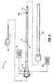
- Fig. 2 illustrates an endoscopic stapling system or instrument constructed in accordance with an embodiment of the invention.
- Figs. 3A - 3C are perspective views showing the stapler head or device of the stapling system of Fig. 2 in three different positions.
- Fig. 4 is a perspective view of the stapler head or device, with the membrane removed, showing first and second members in the device.
- Fig. 5 is a perspective view of the proximal end of the staple housing of the stapler device of Fig. 4 .
- Fig. 6 is a perspective view of the distal end of the staple housing of the stapler device of Fig. 4 .
- Fig. 7 is an exploded perspective view showing elements advanceable within the staple housing during compression and stapling operations.
- Fig. 8 is a plan view of a staple reinforcement device.
- Fig. 9 is a side elevation view of a staple cartridge.
- Fig. 10 is a perspective view of the staple housing similar to Fig. 6 , but showing some of the elements of Fig. 7 within the housing.
- Figs. 11A - 11D are a series of schematic representations of the hydraulic chamber and pistons, illustrating operation of an exemplary hydraulic system during tissue compression and stapling.
- Fig. 11E is similar to Fig. 11D and shows an alternative piston configuration.
- Fig. 12 is a perspective view of the anvil housing of the stapler head of Fig. 4 .
- Fig. 13 is a perspective view of the anvil support.
- Fig. 14 is a plan view of the anvil.
- Fig. 15A is a cross-sectional side view of the cutting device and a first embodiment of a cutting board.
- Fig. 15B is a cross-sectional side view of the cutting device and a second embodiment of a cutting hoard.
- Fig. 16 is a perspective view of the hinged arm assemblies of the stapler head of Fig. 4 .
- Fig. 17 is a top plan view of the stapler head of Fig. 4 in the streamlined position for introduction into the body. Both the membrane and the membrane raiser are not shown for purposes of clarity.
- Fig. 18 is similar to Fig. 17 and illustrates hidden features of Fig. 17 .
- Fig. 19 is a perspective view of the stapler head in an intermediate, partially expanded, position.
- Fig. 20 is a plan view similar to Fig. 17 but showing the stapler head in the intermediate position.
- Fig. 21 is similar to Fig. 20 and illustrates hidden features of Fig. 20 .
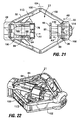
- Fig. 22 is a perspective view of the stapler head in a fully expanded, full compression position.
- Fig. 23 is a plan view similar to Fig. 20 but showing the stapler head in the full compression position.
- Fig. 24 is similar to Fig. 23 and illustrates hidden features of Fig. 24 .
- Figs. 25A - 25B are perspective views showing the staple housing, cartridge and a portion of the membrane raiser. These figures illustrate the steps of detaching a staple cartridge from the staple housing.
- Fig. 26 is a perspective view of the stapler instrument of Fig. 2 , with the staple head removed.
- Fig. 27A is a plan view of the articulating section of the stapler of Fig. 2 , showing interleaved drive fluid lines.
- Fig. 27B shows a drive fluid line having an alternate longitudinally expandable shape.
- Fig. 28 is a cross-sectional side view of the handle of the stapler instrument of Fig. 2 .
- Fig. 29 is a perspective view of the handle of the stapler of Fig. 2 .
- Figs. 30A and 30B are plan views of the proximal face of the staple housing, showing a method for attaching the end plate of the stapler handle to the staple housing.
- Figs. 31A - 31E are a series of drawings schematically illustrating use of the system of Fig. 2 to form a plication in a stomach.
- Figs. 32A-32C are a series of perspective views illustrating use of the stapler of Fig. 2 to acquire, compress, and then staple stomach wall tissue to form a plication in the stomach.
- the membrane is not shown in these drawings.
- Fig. 33 is a top plan view of a plication formed in body tissue.
- Figs. 34 and 35 are perspective views of an alternative stapler head equipped to carry additional tools.
- Figs. 36 and 37 show alternative embodiments of stapler-alignment structure in the stapler device of the invention.
- the present application describes endoscopic fastener-applying devices which in preferred embodiments may be passed transorally into the stomach and used to plicate stomach tissue.
- tissue is drawn inwardly into a vacuum chamber, although tissue may be drawn inwardly using other components (e.g. graspers) that do not involve the use of a vacuum.
- tissue may be drawn inwardly using other components (e.g. graspers) that do not involve the use of a vacuum.
- tissue may be drawn inwardly using other components (e.g. graspers) that do not involve the use of a vacuum.
- graspers e.g. graspers
- the disclosed fastener applying device allows the opposed sections of tissue to be moved into contact with one another, and delivers fasteners that will hold the tissue sections together until at least such time as serosal bonds form between them.
- Each of these steps may be performed wholly from the inside of the stomach and thus can eliminate the need for any surgical or laparoscopic intervention.
- medical devices including, but not limited to any of the types listed above
- the disclosed embodiments include an optional feature that forms a hole or cut in a plication using the fastener-applying device.
- This hole or cut might be formed so that a portion of a medical implant may be passed through or linked to the hole/cut, or it may be formed so as to provoke a healing response that will contribute to the strength of the resulting tissue bond.
- the fastener-applying devices are described as being staplers, and exemplary methods are given with respect to the formation of plications in stomach tissue. It should be understood, however, that the embodiments described herein include features having equal applicability for applying other types of fasteners, and for applying staples or other fasteners for purposes other than formation of plications. More specifically, the term "staple" is used herein to designate any type of fastener that (i) can be pushed through tissue, and (ii) has one or more leg members that when forced against an anvil are crimped to secure the fastener to the tissue and hold tissue fastened tissue fold together. The disclosed embodiments and methods will also find use in parts of the body outside the GI system. Additionally, although the disclosed embodiment features circular stapling and cutting of a concentric hole, modifications are conceivable in which linear stapling can be accomplished, as well as circular or linear stapling without cutting.
- Fig. 2 illustrates one embodiment of a system or instrument 10 for tissue stapling that is suitable for endoscopic use, as well as surgical or laparoscopic use if desired.
- system 12 includes a stapler or stapler instrument 12 having a stapler head or device 14 positioned on a distal portion of a shaft 16.
- a handle 18 on the shaft 16 controls articulation of the stapler head 14 and actuation of the tissue acquisition, tissue compression, and stapling functions of the stapler head 14.
- Vacuum and fluid sources 20, 31 in the system are fluidly coupled to the handle 18 for use in tissue acquisition, compression and stapling as discussed below.
- the vacuum source 20 may be the "house vacuum" accessible through a coupling on the wall of the operating room, or an auxiliary suction pump.
- the stapler may include a switch 21 allowing the user to control airflow between the vacuum source and stapler.
- the stapler device also serves to capture a tissue fold for stapling, and is thus also referred to herein as a tissue capture device for immobilizing a tissue fold, e.g., for fastening the sides of the fold.
- the tissue capture device may operate independently for capturing tissue, e.g., absent a separate stapling mechanism, or may be combined with the stapling elements, as illustrated.
- the fluid source 31 may be a single source of drive fluid (e.g. water, saline, oil, gas) or multiple sources, but in each case the fluid source preferably includes two actuators separately used to control flow into each of two hydraulic lines (one for tissue compression and one for stapling).
- An endoscope 22 in the system is insertable through a lumen in the shaft 16 permits visualization of the plication procedure.
- the system may optionally include an overtube, such an endoscopic guide tube 23, having a lumen for receiving the stapler 12.
- a covering or membrane 24 in the stapler encloses the stapler mechanism to form a vacuum chamber 21 ( Figs. 17-23 ) within the stapler head 14.
- the side exposed to the tissue to be plicated remains uncovered by the membrane 24 to allow tissue to be drawn into the chamber during use.
- the membrane 24 may include a side opening 26 as shown in Fig. 3B .
- Membrane 24 is preferably formed of silicone, elastomeric material, or any other inelastic or elastic flexible or deformable biocompatible material, such as a pleated mylar film, capable of forming a vacuum chamber 21 that will expand in volume to accommodate tissue drawn into chamber 21.
- an articulating section 128 connecting the instrument shaft to the staple head, and described blow with reference to Figs. 26 and 27 .
- the membrane is at least partially transparent.
- the membrane is formed of a material, or includes sections of material, that will allow the user to see through the membrane well enough to confirm (via endoscopic observation) that an appropriate volume of tissue has been acquired into the stapler head prior to staple application.
- the opening 26 may be surrounded by a reinforced section 27 formed of material that will strengthen the area around the opening 26.
- Reinforced section 27 may be formed of a thicker section of the membrane material, and/or a higher durometer material. Alternatively, reinforcing ribs or other structures or element may be formed into or onto the membrane material, or embedded in the membrane material.
- the stapler head 14 is designed to have a minimum profile during insertion to the plication site, and to then transform into a much larger profile device having to large internal volume.
- the vacuum chamber might have an initial internal volume of 0.2 cubic inches, and an expanded volume of 0.6 cubic inches (i.e. the internal chamber volume after subtracting the volume occupied by the stapler head components positioned within the vacuum chamber).
- This large internal volume allows a large volume of tissue to be drawn into the vacuum chamber and stapled.
- the stapler head creates a large plication without requiring invasive techniques for insertion.
- the unique features of the stapler head allow in situ volumetric expansion of the stapler head using a minimum of motion and force input. In particular, as will be seen below with respect to Figs.
- the plication can be sized such that the staples applied to the tissue, such that the two annular staple arrays seen in Fig. 33 are well spaced from the edges of the stapled tissue, minimizing the risk of tissue tearing around the staples.
- stapler head 14 generally includes a first, staple member 25 comprising a proximal staple housing 28, a second, anvil member 27 comprising a distal anvil housing 30, and at least one elongate member but preferably a pair of hinged arm assemblies 32 that operatively connect the two housing as described below.
- the staple housing and anvil housing are arranged to allow tissue to be compressed between contact surfaces on each of the staple housing and the anvil housing.
- the contact surfaces are on a staple holding portion of the staple housing, i.e., the outer face of the staple holder, and an anvil on the anvil housing.
- staple holder 78 shown in Fig. 7
- staple holder 78 functions as a tissue-capture plate having a front, tissue-contacting surface 83, and anvil 96 ((shown in Figs.
- tissue-capture plate 13 and 14 functions as a second tissue-capture plate having a tissue contacting surface 103 confronting surface 83, where these to surfaces serve to capture the tissue fold during operation of the device, as will be described more detail with respect to Figs. 32A - 32C .
- the arm assemblies 32 extend between the staple housing 28 and anvil housing 30 on opposite sides of the stapler head 14. Proximal and distal pins 34, 36 pivotally couple each arm assembly 32 to the staple housing 28 and the anvil housing 30.
- An expansion member comprising a membrane raiser 37 also extends between the staple housing 28 and the anvil housing 30.
- membrane raiser 37 includes a link 38 pivotally mounted to the staple housing by a pin 42, a corresponding link 40 pivotally mounted to the anvil housing by pin 44, and spring wires 46 coupling the links 38, 40 to one another.
- proximal face 48 of the staple housing includes input ports 50a, 50b through which fluid is directed for hydraulic actuation of the tissue compression, stapling, and optional cutting operations of the stapler head. Seals 51 surround the ports 50a, 50b to minimize fluid leakage.
- Vacuum ports 52 are fluidly coupled to a vacuum source 20 ( Fig. 2 ) that is selectively activated to create negative pressure in the vacuum chamber for tissue acquisition.
- the vacuum ports 52 are connected to the vacuum source 20 by flexible tubing (not shown) in the stapler shaft 16 ( Fig. 2 ).
- Mounting holes 54 are used to mount the stapler head 14 to the shaft 16 through the articulating section 128.
- the staple housing 28 includes upper and lower sections 58a, 58b above and below open side sections 56.
- the upper section 58a includes a recess 60 within which the pivot pin 42 for link 38 ( Fig. 4 ) is mounted.
- bores 62 are positioned in the upper and lower sections 58a, 58b to receive pins 34 ( Fig. 4 ) that serve as the proximal pivot points for ami assemblies 32.
- Guide slots 64 extend longitudinally through the upper and lower sections 58a, 58b.
- a hydraulic chamber 66 is disposed within the staple housing 28.
- a dedicated hydraulic circuit for driving the tissue compression and stapling functions of the stapler.
- Chamber 66 is fluidly coupled to the fluid input ports 50a, 50b ( Fig. 5 ).
- fluid driven into the hydraulic chamber 66 via input ports 50a, 50b sequentially advances a system of hydraulic pistons (not shown) that act on other components to compress the tissue, and that drive the staples and cutting element through the compressed tissue.
- Fig. 7 illustrates components of the stapler head that are driven by the hydraulic system for compression, stapling, and cutting. For clarity, these components are shown separated from the staple housing and from each other. In this discussion, the components that are driven by the hydraulic system will be described. The hydraulic system itself is described in a later section in connection with Figs. 11A - 11D .
- Fig. 7 illustrates a drive member which takes the form of a disk 68 in the staple housing.
- disk 68 is positioned such that it will be pushed distally by a hydraulic compression piston (piston 106 in Figs. 11A-11E ).
- the drive member is movable between a first, retracted position shown in Fig. 11A to a second, extended position shown in Figs. 11C and 11D .
- the drive member illustrated here is driven by, but separate from piston 106, it will be appreciated that these two components can be formed of a single-piece member, i.e., as a single-piece drive member including both piston and disc.
- the drive member is coupled to the arm assemblies 32, the anvil housing, and the staple housing so that advancing the drive member distally (toward its extended position) effects tissue compression by bringing the contact surfaces of the staple housing and anvil housing relatively towards one another.
- the combination of disk 68, its driving piston 106, and assembly arm 32 coupling the two housings is also referred to herein collectively as a drive assembly, indicated at 29 in Fig. 10 .
- the drive assembly may further include drive links 114 in the anvil member, which are operatively linked to assemblies 32 as described below.
- disk 68 includes mounting bores 70, a central opening 72, and alignment posts 74.
- disk 68 in the assembled stapler head, disk 68 is coupled to the stapler housing 28, and its axial movement therein constrained, by pins 84 that extend through the housing's guide slots 64 and through mounting bores 70 in the disk 68.
- a portion of the staple housing 28 contains, i.e., is loaded to contain, staples to be fired into the tissue.
- the staples are contained within a staple holder, such as staple cartridge 78, on the staple housing.
- the staple holder may have a number of different configurations. For example, it may be an integral portion of the staple housing, or a separate part mounted or attached to the staple housing, and/or it may be moveable relative to the body of the staple housing to effect tissue compression prior to stapling.
- the staple holder may be a removeable/replaceable cartridge, and/or it may be refillable by inserting additional staples into it.
- the staple holder may be neither replaceable nor refillable, i.e., i.e., in a dive intended for one-time use.
- the staple holder is a removeable staple cartridge 78 that can be replaced with another cartridge after staple filing.
- the staple cartridge is moveable relative to the body of the staple housing to compress the tissue prior to staple firing.
- staple cartridge 78 is positionable within the staple housing, distal to the disk 68, such that distal advancement of the disk by the compression piston pushes the cartridge from a first, retracted position distally to a second, extended position to compress tissue disposed between the cartridge and anvil.
- Grooves 79 on the exterior of the cartridge slide over corresponding ones of the alignment posts 74 during insertion of the cartridge into the stapler head.
- Fig. 10 shows the alignment posts prior to loading of a cartridge into the staple housing.
- the alignment posts 74 may have tapered ends to facilitate loading of the cartridge over the posts, It will be appreciated that the alignment posts hold the cartridge against angular movement within housing 28 during stapler operation.
- cartridge 78 includes a number of staple locations 80, each housing a staple, such as staples 158 seen in Fig. 33 .
- the staple cartridge is equipped with bosses 81 to retain a staple line reinforcement device 83 of the type shown in Fig. 8 and disclosed in detail in commonly-owned U.S. Application No. 11/542,457 , entitled ENDOSCOPIC PLICATION DEVICES AND METHODS, filed October 3, 2006, and published September 20, 2007 as US 20070219571 .
- this type of reinforcement device 83 may be a ring or other element positionable against the distal face of the staple cartridge.
- openings 85 in the ring align with prongs of some of the staples in the cartridge.
- these prongs pass through associated ones of the openings 85 and capture the ring 83 against the adjacent body tissue.
- a number of undercut bosses 81 on the anvil-facing side of the cartridge may be used to lock the reinforcement device 83 in place on the face of the staple cartridge.
- Other positive shapes such as mushrooms, hooks, and tilted bosses could be used to accomplish the same end.
- Negative shapes, such as pockets or grooves formed into the surface of the cartridge, may also be employed to engage corresponding features on the reinforcement device 83.
- the reinforcement device may be held in place on the cartridge using adhesives.
- a cutter element 86 extends through the central opening 72 ( Fig. 7 ) of the disk 68.
- the cutter element is shown as a tubular punch having a sharpened wall and a lumen 87, but may be provided in alternative forms.
- a staple pusher 76 is mounted to the cutter element, distally of the disk as can be seen in the assembled view of Fig. 10 .
- Staple pusher 76 includes pusher elements 82 proportioned to slide into the cartridge's staple locations 80 as the staple pusher 76 is advanced into the staple cartridge 78, thus driving the staples from the cartridge.
- a hydraulically-driven staple piston (shown at 116 in Figs. 11A-11E ) in the hydraulic chamber 66 (carried within a hydraulic chamber formed by piston 106) is coupled to the cutter element 86 such that advancement of the stapler piston advances the staple pusher 76 and cutter element 86 in a distal direction.
- Figs. 11A and 11B schematically show the fluid flow in the hydraulic chamber 66 of the staple housing 28 during both compression and stapling stages of actuation.
- compression piston 106 is disposed within hydraulic chamber 66.
- Disk 68 (also shown in Figs. 7 and 10 ) is positioned in contact with or slightly distal to piston 106.
- Compression piston 106 is generally cup-shaped, having a rear wall 108 and a side wall 110 enclosing an interior 111.
- O-ring seals 112 are spaced-apart on a proximal portion of the side wall 110.
- Channels 115 are formed through the side wall 110, between the o-ring seals 112.
- a second piston referred to as the staple piston 116
- staple piston 116 is positioned in the interior 111 of compression piston 106, against the rear wall 108.
- cutting element 86 Fig. 7
- An o-ring seal 118 surrounds a portion of the staple piston 116 that is distal to the channels 115 in the compression piston.
- a first fluid channel 120 extends from fluid port 50a in the stapler housing 28 to a proximal section of the hydraulic chamber 66.
- a second fluid channel 122 extends from fluid port 50b in the stapler housing to a more distal section of the hydraulic chamber 66.
- Fluid flow from port 50a and fluid channel 120 against the compression piston cylinder is shown in Fig. 11A .
- Fluid pressure within the hydraulic chamber 66 advances the compression piston 106, with the stapler piston 116 within in it, in a distal direction, from a first, retracted position, shown in Fig. 11A to a second, extended position shown in Figs. 11C and 11D.
- Fig. 11B shows the compression piston 106 approaching the end of its travel, i.e., fully extended position.
- channel 115 in the compression piston 106 aligns with channel 122 in the housing, allowing fluid introduced through fluid port 50b to enter the interior of the compression piston 106 via channel 122.
- the fluid entering the interior of the compression piston drives the staple piston distally as shown in Fig. 11D , from a first, retracted position shown in Figs 11A-11C , to a second, extended position shown in Fig. 11D .
- a third piston 117 is provided for separately driving the cutting element 86.
- fluid introduced into a third drive fluid port 50c causes advancement of the third piston 117 from a first, retracted position to a second extended position (not shown).
- the pistons 106, 116 and 117 and associated fluid paths may be arranged so that fluid cannot enter the interior of the stapler piston to advance the cutting piston 117 until compression piston 106 has traveled to the tissue-compression position and stapler piston 116 has in turn traveled to the stapling position.
- the anvil housing (identified by numeral 30 in Fig. 4 ) in anvil member 27 will next be described with reference to Fig. 12 .
- the anvil housing 30 includes mounting bores 88 for receiving pivot pins 36 at the distal end of the hinged arm assemblies 32.
- the upper section of the anvil housing 30 includes a section 94 through which the pivot pin 44 for link 40 ( Fig. 4 ) is mounted.
- a central bore 90 extends longitudinally through the anvil housing 30.
- An anvil support 92 ( Fig. 13 ) is longitudinally slidable within the bore. Both the bore 90 and the anvil support 92 are preferably formed to have non-circular cross-sections (such as the illustrated rectangular cross-section) with flat bearing surfaces to prevent rotation of the piston within the bore.
- Fig. 13 shows the anvil support 92 separated from the anvil housing 30.
- the distal portion of the anvil support 92 is split into upper and lower plates 95a, b.
- Plate 95a has a bore 93 axially aligned with a similar bore in plate 95b.
- the proximal portion of the anvil support 92 carries the anvil 96.
- anvil 96 includes a plurality of indentations 98 positioned such when staples are driven from the staple cartridge, each staple leg engages one of the indentations, which causes the staple leg to fold or crimp.
- the anvil is designed for a staple array having two annular rings of offset staples, five staples per ring.
- a central opening 97 extends through the anvil 96 and is contiguous with a lumen in the anvil support 92.
- the anvil 96 and the staple cartridge 78 are the two parts of the stapler head which exert force on the tissue to be stapled.
- the preferred anvil and cartridge are designed to use a minimal amount of material surrounding the indentations 98 of the anvil 96 and the staple locations 80 of the cartridge 78 - so that the amount of anvil/cartridge surface area contacting the tissue is as small as possible.
- a smaller footprint will damage less tissue than would a larger footprint, since a smaller area of tissue is squeezed between the anvil and cartridge.
- the tissue that does get squeezed experiences more pressure from the given force because the force is distributed over a smaller area.
- the minimized footprint creates more pressure on the tissue with less force. This is advantageous from a mechanical standpoint because the stapler head need not supply or withstand as much force as would be needed with a larger-footprint cartridge and anvil.
- the staple cartridge 78 has an outer wall that tracks the contours of the staples housed within it, thus forming a number of pedals 73 surrounding the outer staple positions or slots 80a, with the grooves 79 disposed between the pedals, adjacent to the inner staple positions 80b.
- the staple positions 80a, 80b preferably each include a back wall 71a and a retaining element attached to the wall and positioned to retain a staple between the retaining element and the back wall.
- the retaining element comprises a pair of wings 71b that curve inwardly from the back wall 71 to define a slot that is sufficiently bounded to retain a staple within the staple position, but that is preferably not bounded around its full circumference.
- the anvil has a similar pedal arrangement, as shown in Fig. 13 .
- a plate 99 is positioned on the anvil 96 such that the distally-advancing cutting element 86 will advance into contact with the plate 99 during tissue cutting.
- the plate 99 may be seated within the opening 97 in the anvil.
- the plate 99 which will also be referred to as the "cutting board”, has a hole 101 in it which relieves the pressure of the captured tissue and prevents hydraulic locking, a condition in which the punch and plate create a closed volume. If it is desired to move the cutting element 86 after contact is made, pressure will increase inside this closed volume and it will resist further motion. This may prevent or adversely affect tissue cutting.
- the cutting board is preferably designed so as to not serve as a hard stop against advancement of the cutting element 86. If the cutting element 86 is stopped by the cutting board, the stapling piston will also be stopped and incomplete staple formation may result. Therefore, it is preferred that the cutting element 86 is allowed to penetrate or displace the cutting board during and after the tissue is cut; that is the cutter can advance slightly once initial contact with the board is made.
- Figs. 15A and 15B illustrate the cutting element 86 advanced into contact with different embodiments of cutting boards.
- the material of cutting hoard 99a is a relatively soft material, such as an elastomeric silicone, which is cut or penetrated by the advancing cutting element as shown. This material allows the sharp distal end of the cutting element to move into the cutting board during the final stage of staple formation.
- the cutting board 99b can be made of a harder material positioned with a compressible object such as an elastomeric spring 99c behind it. In the figure, this spring is an o-ring. Advancement of the cutting element 86 against the cutting board 99b causes the cutting board to be displaced distally against the spring 99c.
- the advancing cutting element 86 experiences increasing resistance as the o-ring is compressed.
- Other spring shapes and materials, such as coiled wire, spring washers and leaf springs can be used to achieve the same result.
- the chamfer 99d on the surface of the cutting board 99b may help to align the cutting element 86 as it is forced into contact with the cutting board.
- each arm assembly has a first arm section 100 pivotally coupled to the staple housing and a second arm section 102 pivotally coupled between the first arm section and the anvil housing. While not present in the illustrated embodiment, additional arm sections may be positioned between the first and second arm sections.
- each arm assembly includes a proximal arm 100 and a distal arm 102 joined to one another to form a hinge 104.
- Each of the proximal arms 100 has a longitudinal cutout 108 and an arm spreader 113 pivotally mounted within the cutout 108.
- the distal end of each arm spreader 113 includes a bore 112.
- Pin 84 is positioned within the bore 112. As disclosed in connection with Fig. 10 , this pin 84 extends through the disk 68 and has ends that ride within the slots 64 ( Fig. 6 ) on the lower and upper sections of the stapler housing.
- Distal arms 102 of the arm assemblies include pins 36 which, as discussed, are pivotally mounted to the anvil housing 30 ( Fig. 4 ).
- a pair of drive links 114 are provided, each of which has a first end pivotally attached to a corresponding one the distal arms 102 and a second end pivotally coupled to a common pin 116.
- pin 116 is positioned in the bores 93 of the upper and lower plates 95a, 95b of the anvil support (see plates 95a, b in Fig. 12 ).
- drive links 114 act on the pin 116 to push the anvil support in a proximal direction, causing the anvil to advance proximally towards the staple cartridge.
- the anvil may be driven within its housing independently of the arm assemblies, by a direct hydraulic drive mechanism carried in the anvil housing.
- the drive mechanisms in the two housings are coordinated so that the staple holder and anvil are moved toward one another in their respective housings at the same time.
- the stapler head is positioned with the opening 26 in the membrane 24 in contact with tissue at the location at which plication creation is desired.
- Vacuum source 20 ( Fig. 2 ) is activated to apply vacuum to the inside of the vacuum chamber defined by the membrane. Tissue in contact with the opening 26 ( Fig. 3B ) will be drawn into the vacuum chamber between the staple housing 28 and the anvil housing 30. After the tissue is drawn in, the stapler profile is changed, expanding the volume of the chamber within the membrane.
- the streamlined position of the stapler head 28 prior to expansion is shown in Figs. 4 , 17 and 18 .
- the hinged arm assemblies 32 and membrane raisers 37 are in generally straight orientations.
- the proximal arms 100 serve as the drive arms for chamber expansion and tissue compression. Motion of these arms is initiated when water under pressure is forced into the hydraulic circuit of the staple housing.
- the fluid pressure advances disk 68 (by action of the compression piston 106, not shown in Fig. 19 ).
- Disk 68 in turn pushes the staple cartridge 78 toward the anvil 96 as shown in Figs. 19-21 , causing the staple cartridge 78 to extend further from the staple housing 28.
- Both the disk 68 and the ann spreaders 113 are coupled to the pins 84. For this reason, the longitudinal movement of the disk 68 within the stapler housing 28 will carry the pins 84 distally within their corresponding slots 64. The arm spreaders 113 will consequently pivot relative to the pins 84, driving the proximal arms 100 outwardly. Outward movement of proximal arms 100 at hinge 104 causes the distal arms 102 to also pivot outwardly at hinge 104, fonning an angle between the proximal and distal arms 100, 102. Naturally, formation of the angle between the arms 100, 102 shortens the effective length between the remote ends of the arms, causing the distal pins 36 of the distal arms 102 to carry the anvil housing 30 towards the staple cartridge.
- the pivoting movement of the distal arms 102 further causes drive links 114 to act on pin 116 to push the anvil support in a proximal direction. This moves the anvil support relative to the anvil housing in a proximal direction at the same time the anvil housing is also moving proximally.
- one motion that of the hydraulically driven compression piston, creates at least three motions, illustrated by arrows Al, A2 and A3 in Figs. 19-21 .
- These three motions include: the staple cartridge 78 moving relative to the staple housing in a direction towards the anvil 96 (arrow A1), the anvil housing 30 moving toward the staple housing 28 (arrow A2) and the anvil 96 itself moving relative to the anvil housing 30 in a direction towards the cartridge (arrow A3).
- This compound motion of the anvil toward the staple cartridge enables a small displacement of the compression piston to quickly compress tissue in the grip of stapler.
- the multiplication of motion also enhances force transmission between the two housings by keeping the angle at hinge 104, between the proximal (driven) arm and the distal (drive) arm, as large as possible.
- the slots and associated components are dimensioned to set the desired separation distance between the tissue contact surfaces on the stapler side and the anvil side of the stapler head.
- Exemplary separation distances for use in stomach wall plications might include approximately 0.06-0.07 inches (e.g. for use with staples having legs of 5.5mm length) or 0.109 inches for 6.5mm leg length staples.
- Application of additional pressure into the hydraulic circuit will not compress the tissue any further.
- the stapling function is effectively locked out until tissue compression is complete.
- fluid introduced via the fluid port 50b ( Fig. 11A ) into the staple fluid channel 122 prior to completion of tissue compression will leak until the two o-rings 112 of the compression piston 106 are straddling the inlet 114. This design prevents premature staple firing.
- the arm spreaders 113 are nearly perpendicular to the longitudinal centerline of the stapler head. Once tissue is compressed between cartridge 78 and anvil 96, the tissue is ready for stapling.
- Stapling is initiated by introducing hydraulic fluid through port 50b ( Fig. 5 ).
- the staple piston advances, pushing cutting element 86 ( Figs. 7 and 10 ) towards the anvil 96. Because the staple pusher 76 is mounted to the cutter 86, this action carries the staple pusher 76 through the cartridge 78 where it simultaneously pushes all staples through the tissue. Staple piston travel is limited by internal stops, and is preset to yield optimal staple formation.
- staple pressure is released and a spring (not shown) returns the staple pusher 72 to its base position. Releasing fluid pressure will allow the deflected spring wires 46 on membrane raiser 37 to return the staple head to its minimum profile configuration and release the plication from the stapler. Once outside the patient, the used staple cartridge can be ejected and a new one installed.
- Figs. 25A - 25C illustrate one method for retaining a removable staple cartridge 78 within the staple housing.
- the cartridge is spring-loaded into the staple housing and retained by two latches 170 (one visible), each pivotable relative to a fulcrum 172.
- the fulcrum 172 may be coupled to the disk 68 by pin 84.
- Each latch 170 includes a catch 174 which engages a corresponding catch 176 on the cartridge.
- the latch 170 is preferably spring biased to urge the catch 174 inwardly towards the cartridge.
- each latch 170 Depressing the proximal end 175 of each latch 170 as shown by arrow P in Fig. 25B pivots the latch against this bias, causing ejection of the staple cartridge.
- a new staple cartridge may then be positioned with its grooves 79 aligned with alignment posts 74 as shown in Fig. 25C and then pushed towards the staple housing.
- catch 174 rides over the tapered proximal portion 178 of the catch 176. Once catch 174 passes over the distal end 180 of the catch 176, it drops inwardly towards the cartridge due to its spring bias, thus engaging the cartridge.
- a click will be felt or heard as the latches engage the new cartridge.
- tissue fold is captured between the outer face of the staple cartridge and the confronting face of the anvil.
- variations in the thickness and or compressibility of regions of the captured tissue may bias the stapling operation off-center, i.e., off axis, causing the staple legs to be received out of position within their associated anvil indentations, with the result that one or more of the staples may fastened defectively, e.g., without complete folding of the staple legs, and/or the array of staples may be offset with respect to the center axis of the device, causing some staples, for example, to be too close to the hole cut in the center of the stapled fold.
- the device of the invention may include alignment structure to hold to proximal and distal members of the device in axial alignment just prior to and during the stapling operation.
- the alignment structure is shown in side sectional views in Figs. 36 and 37 . Shown in Fig. 36 is the portion of the staple device 12 that includes anvil 96 and cutting board 99a on distal member 27, and cutter 86 on proximal member 25.
- the two members, and the staple cartridge and anvil carried thereon are first moved together, to capture a tissue fold between the confronting faces of the cartridge and anvil, as illustrated in Figs. 22 and 23 .
- Staple piston 116 is then moved from its retracted to its extended position, as seen in Fig. 24 , to move the cutter against cutting board 99a, as shown, and drive the staples in the staple cartridge against the anvil.
- the alignment structure includes a pin held axially within cutter 86 for movement therewith, and a pin-receiving slot formed in a bushing 164 supported within a portion of housing 27 attached to anvil 96 for axial movement therewith.
- bushing 164 is spring loaded, through a spring 166, within housing 27 in a direction that resists movement of the pin toward the bushing, allowing the cutter and attached pin, which has now penetrated through the captured tissue, to seat in the beveled end of the bushing.
- the two device members are maintained in axial alignment, so that the stapling operation occurs with all staples positioned in alignment with the respective to the associated anvil indentations.
- the staple piston and drive member are retracted to release the stapled tissue and return the device to its linear condition.
- the embodiment of device 12 shown in Fig. 37 is similar to that just described, but where the alignment pin 168 carried in the housing of cutter is spring biased, by a spring 174, in the direction of the second member, and a pin-receiving slot 170 is in a fixed-position bushing 172 carried below the anvil (not shown) in member 27.
- motion of the two members toward one another, once the pin has been initially seated in the bushing slot is accommodated by movement of the pin in a direction away from the second member, as the staple piston continues to move toward its fully extended position, to cut and staple the tissue captured between the two members, as described above.
- the stapler shaft 16 connecting the handle 18 and the stapler head 14 is flexible enough to conform to the curvature of the upper digestive tract, yet maintains the ability to transmit enough torque to rotate the stapler head.
- the shaft is formed with sufficient stiffness to allow it to be pushed down esophageal guide tube 23. Suitable materials include
- Fig. 26 shows a distal portion of the shaft 16, with the stapler head removed from the shaft.
- shaft 16 includes an endoscope lumen 124 through which an endoscope is advanced to allow visualization of a stapling operation.
- Side lumens 126 may also be provided for receiving other instruments useful during the procedure.
- An articulating section 128 is positioned at the distal end of the shaft 16, between the shaft 16 and the stapler head 14 so as to allow the stapler head to be articulated relative to the shaft.
- Tubing coupled to the vacuum source and the source of hydraulic fluid extends from the handle and through the shaft 16 and the articulating section 128.
- Fig. 27A shows one configuration that may be used for the hydraulic fluid lines 130.
- the hydraulic fluid lines are subjected to significant deflection and elongation in the articulating section of the stapler. They are also subjected at times to fluid pressure which may be in excess of 1,500 psi.
- hydraulic lines in industrial applications are flexible and have a working loop of extra tubing that accommodates length changes during use.
- the illustrated configuration for the hydraulic lines is a lower profile solution particularly suitable for an endoscopic device having space constraints.
- a preferred hydraulic line is a tube 130 having a portion that is shaped into a longitudinally expandable shape so that it can accommodate effective length changes during bending.
- the longitudinally expandable portion of the tube is preferably disposed within the articulating section 128 of the stapler 12.
- the longitudinally expandable shape is a coil shape as shown in Fig. 27A .
- the tube 130 may be formed into other longitudinally expandable shapes, such as regular or irregular undulating shapes ( Fig. 27B ).
- the preferred material for the tubes 130 is stainless steel hypotube, although other materials may instead be used.
- two drive fluid lines are provided, one for actuating tissue compression, and the other for staple application (and cutting when used).
- the tubes are coiled together as shown in Fig. 27A .
- two or more coiled tubes may be nested one inside the other. As the articulating section bends, it forces the coiled tubes 130 to bend and to change length in response to bending.
- the coiled tubes behave just as coiled wires would during these motions and are thus able to change length, deflect, and follow the contour of the articulating section without compromising flow through the lumens of the tubes or imparting undue stress to the connections at either end of the hydraulic system.
- the longitudinally expandable shapes for the fluid lines may be suitable for use in allowing delivery of fluid to the operative ends of other types of articulating medical devices, such as catheters or endoscopic devices for delivering therapeutic agents or irrigation fluids past an articulating or bendable section of the device.
- articulating section 128 is comprised of a spine formed of a plurality of links 132 strung over a pair of pull cables 134 (only one shown in Fig. 26 ).
- engagement of the pull cables allows the stapler head 14 to be articulated in two directions through a range of motion of approximately 90 degrees in one direction (see Fig. 3B ) to 175 degrees in the opposite direction (see Fig. 3C ).
- Each pull cable is anchored at or near the stapler head, such as at the distal most link 132 of the stapler housing 28.
- the handle 18 includes a rotating knob 136 that may be selectively rotated in a clockwise or counterclockwise to articulate the stapler head up or down. Rotation in one direction applies tension to one of the pull cables to cause the stapler head to bend downwardly, whereas rotation in the opposite direction puts tension on the other cable, causing the head to bend upwardly.
- the knob 136 includes an internal threaded bore 138. Knob 136 is partially restrained within the handle 18 so that it remains fixed within the handle but can rotate freely. A carriage 140 having a threaded exterior surface is positioned within the threaded bore 128 of the knob. The threads within the bore 138 are engaged with the threads on the carriage 140 so that rotation of the knob causes the carriage 140 to translate, but not rotate, within the handle.
- Each of the two pull cables is terminated on a different member in the handle.
- Cable 134a is mounted on the sliding carriage and cable 134b is mounted to a stationary part of the handle 18.
- Each cable extends through a corresponding sheath.
- Cable 134a extends through a sheath 135a having a proximal end fixed to a stationary part of the handle 18.
- Cable 134b extends through a sheath 135b having a proximal end mounted to the sliding carriage.
- the cables 134a,b and sheaths 135a,b are arranged such that translation of the carriage in one direction will cause deflection of the stapler head in one direction, and translation of the carriage on the other direction will deflect the stapler head in another direction.
- knob 136 if knob 136 is rotated to causes the carriage 140 to translate to the left of the page, cable 134a will be tensioned and cable 134b will stacken, causing the stapler head to articulate in a first direction (e.g. upwardly). Rotation of the knob 136 in the opposite direction will advance the carriage to the right of the page, releasing tension on cable 134a and pushing sheath 135b over the cable 134b towards the distal end of the staple head, causing articulation in the second direction (e.g. downwardly) as the sheath 135b is advanced against a distal portion of the shaft 16.
- a first direction e.g. upwardly
- Rotation of the knob 136 in the opposite direction will advance the carriage to the right of the page, releasing tension on cable 134a and pushing sheath 135b over the cable 134b towards the distal end of the staple head, causing articulation in the second direction (e.g. downwardly) as the sheath 135b is advanced against a
- the proximal portion of sheath 135b is provided with sufficient working length prevent it from being placed under tension when the carriage moves distally.
- the positioning of the knob is advantageous in that the hand movement required for stapler articulation is always the same, regardless of the rotational orientation of the stapler. Also, the use of the threaded knob can prevent unintentional relaxation of the deflection angle, even if the knob is provided without a lock to retain its rotational position.
- the endoscope lumen 124 extends along the center axis of the stapler.
- the positioning of the lumen and the coaxial relationship of the articulation knob in relative to the endoscope 124 allows the endoscope and stapler to be rotated independently without one interfering with one another.
- the user may rotate the handle 18 and shaft 16 while maintaining the rotational position of the endoscope.
- the stapler 12 may be designed to permit the stapler head 14 to be discarded while allowing the shaft 16 and handle 18 to be sterilized and re-used.
- One mechanism for removably coupling the stapler head to the shaft 16 is illustrated, although others are readily conceivable (e.g. a slip coupling type arrangement).
- an end plate 142 is mounted to the distalmost one of the links 132.
- Each of the end plate 142 and the corresponding rear surface of the stapler head are provided with latch features that allow the end plate and stapler head to be engaged to one another.
- End plate 142 includes a cantilevered pin 144 having a peg 145 (which may be a spring pin), a central opening 146, and a pair of u-shaped catches or engagement edges 148 along its edges. Hydraulic feed holes or openings 156a, b are formed through the end plate 142.
- the hydraulic tubes that deliver hydraulic fluid to the stapler head are preferably welded to the end plate to allow fluid from the tubes to be directed through the feed holes 156a, b.
- Figs. 30A and 30B show the rear surface 48a of the staple housing, which has been somewhat modified relative to Fig. 5 .
- the hydraulic input ports or openings 50a, 50b are repositioned as shown.
- the rear surface 48a has been modified to include a pair of catches or engagement edges in the form of undercut bosses 150, plus an aligning pin 152, and a hole 154. The snap-on connection of shaft to stapler device;
- Figs. 30A and 30B show the end plate 142 positioned against the rear surface 48a of the staple housing.
- the other features of the articulating section 128 are not shown in Figs. 30A and 30B for clarity.
- the plate 142 attached to the handle assembly, is pressed against the rear surface 48a of the staple housing as shown in Fig. 30A .
- the plate is rotated in a clockwise direction, causing the peg 145 ( Fig. 26 ) of the cantilevered pin 144 to engage hole 154 in the rear surface of the staple housing.
- endoscopic guide tube 23 is advanced into the stomach via the mouth and esophagus.
- the endoscope 22 is inserted into the endoscope channel in the stapler handle (not shown) and advanced down the lumen of the stapler handle.
- the stapler/endoscope are simultaneously passed through the endoscopic guide tube towards the stomach. Once the stapler and endoscope reach the gastroesophageal junction region of the stomach, the position of the stapler is maintained while the endoscope is advance further into the stomach.
- the stapler head 14 is advanced to the desired depth and location in the stomach. Using the articulation controls on the stapler handle, the angular orientation of the stapler head is adjusted to allow positioning of the stapler head 12 at the pre-identified target tissue as shown in Fig. 31 A .
- the opening 26 in the membrane 24 is positioned against the target tissue.
- the endoscope 22 is placed in a retroflexed position as shown.
- the vacuum source 20 ( Fig. 2 ) is coupled to the vacuum port on the handle external to the body, and vacuum pressure is applied to draw tissue 17 through the opening 26 and into the vacuum chamber defined by membrane 24 as shown in Figs. 31B and 32A . Acquisition of the target tissue will be readily identified endscopically through the wall of transparent membrane 24 on the stapler head.
- the fluid source (is shown) is coupled to the handle. Once it has been visually confirmed that a sufficient amount of tissue has been acquired, fluid is introduced to cause compression of the tissue and expansion of the arm assemblies 32 and membrane raiser 37 as shown in Figs. 32B and 31C . As can been seen, the expansion of the arm assemblies and the membrane allows a large volume of tissue to be acquired into the vacuum chamber and displaced further into the chamber during tissue compression. As noted earlier, the drawing in of tissue into the expanded chamber during operation, well “above" the staple holder and anvil in Figs. 32B and 32C , provides a relatively large margin of tissue around the stapled portion of the tissue, reducing the risk of tissue tearing or tissue-fold weakness near the stapled portion of the tissue. The captured tissue fold is indicated at 17a.
- a plication P indicated at 17b in Fig. 33 .
- the compression and stapling hydraulic sources are then deactivated to release fluid pressure within the hydraulic circuit.
- the spring wires of the membrane raiser 37 help to restore the stapler head 14 to its original streamlined configuration, allowing the stapler head to be withdrawn from the tissue as shown in Fig. 31E .
- the stapler head may be articulated relative to the shaft to assist in moving the stapler head away from the plication P.
- the staples 158 are arranged in two concentric rings of five staples, with the staple reinforcement device 83 retained by the staples and distributing forces around the staple pattern as shown.
- the plication P includes a hole H formed by the cutting element, through which various implants or anchors for various implants can be placed.
- the stapler 12 is briefly withdrawn from the endoscopic guide tube and the staple cartridge is replaced in the manner described in connection with Figs. 25A - 25C . The procedure is repeated until all desired plications have been formed.
- the system may be packaged with instructions for use instructing the user to use the various disclosed features to perform a stapling procedure using methods disclosed herein.
- Figs. 34-35 show a modified stapler in which the membrane and membrane raiser have been removed, and in which the staple housing 28 has been modified for the attachment of tools.
- the staple housing 28 includes a pair of grooves 160 proportioned to receive tools 162. Tools 162 may be seated in these grooves 160 and mounted to the staple housing as shown in Fig. 35 . This attachment will provide for a stable base from which to actuate the tools.
- the tools may be self-articulating, or the staple housing 28 may be equipped with devices 164 for moving the tools between streamlined positions for insertion of the assembly into a body cavity, and a deployed position such as that shown in Fig, 35 .
- Tools similar to those in Fig. 35 might be used for tissue acquisition, by reaching between the cartridge and anvil and used to engage tissue and pull the tissue into position between the cartridge and anvil so that it may be stapled, or otherwise affected by various features added to or in place of the anvil and cartridge.
- Procedures which may benefit from adaptation of the stapler include, but are not limited to gastroplasty, stoma adjustment, polyectomy, lead placement, bleeding control, perforation or hole closure, biopsy and tumor removal.
Abstract
Description
- The present invention relates generally to the field of systems and methods for performing endoscopic surgery, and specifically to systems and methods for endoscopic stapling of tissue within body cavities.
- An anatomical view of a human stomach S and associated features is shown in
Fig. 1A . The esophagus E delivers food from the mouth to the proximal portion of the stomach S. The z-line or gastro-esophageal junction Z is the irregularly-shaped border between the thin tissue of the esophagus and the thicker tissue of the stomach wall. The gastro-esophageal junction region G is the region encompassing the distal portion of the esophagus E, the z-line, and the proximal portion of the stomach S. - Stomach S includes a fundus F at its proximal end and an antrum A at its distal end. Antrum A feeds into the pylorus P which attaches to the duodenum D, the proximal region of the small intestine. Within the pylorus P is a sphincter that prevents backflow of food from the duodenum D into the stomach. The middle region of the small intestine, positioned distally of the duodenum D, is the jejunum J.
-
Fig. 1B illustrates the tissue layers forming the stomach wall. The outermost layer is the serosal layer or "serosa" S and the innermost layer, lining the stomach interior, is the mucosal layer or "mucosa" MUC. The submucosa SM and the multi-layer muscularis M lie between the mucosa and the serosa. - There are a number of applications for endoscopic application of fasteners such as staples to tissue within a body cavity. Some of those applications involve forming tissue structures such as plications or folds in tissue of the body cavity.
- Several prior applications, including International Application No.
WO 2005/037152 having an international filing date of October 8, 2004 and U.S. ApplicationUS 2008065122 describe methods according to which medical implants are coupled to tissue structures formed within the stomach. According to these applications, devices for inducing weight loss (e.g. by restricting and/or obstructing flow of food into the stomach, and/or by occupying a portion of the stomach volume) may be coupled to tissue tunnels or plications formed from stomach tissue. - For example,
US 2008065122 describes a restrictive and/or obstructive implant system for inducing weight loss. In one embodiment, flexible loops are coupled to tissue plications formed in the gastroesophageal junction region of the stomach. An implant, such as a flow restrictive and/or obstructive implant, is passed through the loops 2 and thus retained in the stomach. - In other instances, tissue plications may themselves be sufficient to provide the necessary treatment. For example, the plications may be used to reduce stomach volume or form a flow restriction within the stomach as disclosed in
WO 2005/037152 , and inUS2007/0219571 , upon which the two part form of appended claim 1 is based. - Other types of implants may be coupled to such plications or other tissue structures for a variety of purposes. These implants include, but are not limited to prosthetic valves for the treatment of gastro-esophageal reflux disease, gastric stimulators, pH monitors and drug eluting devices that release drugs, biologics or cells into the stomach or elsewhere in the GI tract. Such drug eluting devices might include those which release leptin (a hormone which creates feelings of satiety), Ghrelin (a hormone which creates feelings of hunger), octreotide (which reduces Ghrelin levels and thus reduces hunger), Insulin, chemotherapeutic agents, natural biologics (e.g. growth factor, cytokines) which aid in post surgery trauma, ulcers, lacerations etc. Still other implants might be of a type which might provide a platform to which specific cell types can adhere, grow and provide biologically-active gene products to the GI tract, and/or a platform for radiation sources that can provide a local source of radiation for therapeutic purposes, or provide a platform whereby diagnostic ligands are immobilized and used to sample the GI tract for evidence of specific normal or pathological conditions, or provide an anchor point for imaging the GI tract via cameras and other image collecting devices.
- The prior applications listed above, address the desirability of forming tissue plications, pockets or tunnels in a way that regions of serosal tissue (i.e. the tissue on the exterior surface of the stomach) are retained in contact with one another. Over time, adhesions formed between the opposed serosal layers create strong bonds that can facilitate retention of the plication/pocket/tissue over extended durations, despite the forces imparted on them by stomach movement and implanted devices.
- Regardless of the application for which a plication is being formed, it is highly desirable to form that plication using steps carried out from within the stomach using instruments passed down the esophagus, rather than using more invasive surgical or laparoscopic methods. The present application describes endoscopic staplers which may be passed transorally into the stomach and used to form serosal-to-serosal plications in a stomach wall.
- The invention is a stapler device (12) for applying a staple to a tissue as set out in appended claim 1. Preferred embodiments are defined by the dependent claims.
- Also disclosed is a method for capturing a tissue fold by the steps of:
- (a) drawing tissue (17) into a vacuum chamber (21) defined by first and second relatively movable members (25, 27) and a membrane, such as an elastomeric or pleated membrane 24), extending between the two,
- (b) advancing a first tissue-contact plate (78) and a second tissue-contact plate (96) contained within the first and second members, respectively, toward one another by independent movement of the first and second tissue-contact plates (78, 96) staple within their associated members (25, 27, respectively, and by moving the second member toward the first member;
- (c) by continued application of vacuum during said advancing, continuing to draw tissue into said chamber until a tissue fold (17a) is captured between the first and second tissue-contact plates.
- The features of the invention will become more fully apparent when the following detailed description of the invention is read in conjunction with the accompanying drawings.
-
Fig. 1A is a schematic illustration of a human stomach and a portion of the small intestine, as known in the prior art. -
Fig. 1B is a cross-sectional perspective view of a portion of a stomach wall, illustrating the layers of tissue forming the wall, also as known in the prior art. -
Fig. 2 illustrates an endoscopic stapling system or instrument constructed in accordance with an embodiment of the invention. -
Figs. 3A - 3C are perspective views showing the stapler head or device of the stapling system ofFig. 2 in three different positions. -
Fig. 4 is a perspective view of the stapler head or device, with the membrane removed, showing first and second members in the device. -
Fig. 5 is a perspective view of the proximal end of the staple housing of the stapler device ofFig. 4 . -
Fig. 6 is a perspective view of the distal end of the staple housing of the stapler device ofFig. 4 . -
Fig. 7 is an exploded perspective view showing elements advanceable within the staple housing during compression and stapling operations. -
Fig. 8 is a plan view of a staple reinforcement device. -
Fig. 9 is a side elevation view of a staple cartridge. -
Fig. 10 is a perspective view of the staple housing similar toFig. 6 , but showing some of the elements ofFig. 7 within the housing. -
Figs. 11A - 11D are a series of schematic representations of the hydraulic chamber and pistons, illustrating operation of an exemplary hydraulic system during tissue compression and stapling. -
Fig. 11E is similar toFig. 11D and shows an alternative piston configuration. -
Fig. 12 is a perspective view of the anvil housing of the stapler head ofFig. 4 . -
Fig. 13 is a perspective view of the anvil support. -
Fig. 14 is a plan view of the anvil. -
Fig. 15A is a cross-sectional side view of the cutting device and a first embodiment of a cutting board. -
Fig. 15B is a cross-sectional side view of the cutting device and a second embodiment of a cutting hoard. -
Fig. 16 is a perspective view of the hinged arm assemblies of the stapler head ofFig. 4 . -
Fig. 17 is a top plan view of the stapler head ofFig. 4 in the streamlined position for introduction into the body. Both the membrane and the membrane raiser are not shown for purposes of clarity. -
Fig. 18 is similar toFig. 17 and illustrates hidden features ofFig. 17 . -
Fig. 19 is a perspective view of the stapler head in an intermediate, partially expanded, position. -
Fig. 20 is a plan view similar toFig. 17 but showing the stapler head in the intermediate position. -
Fig. 21 is similar toFig. 20 and illustrates hidden features ofFig. 20 . -
Fig. 22 is a perspective view of the stapler head in a fully expanded, full compression position. -
Fig. 23 is a plan view similar toFig. 20 but showing the stapler head in the full compression position. -
Fig. 24 is similar toFig. 23 and illustrates hidden features ofFig. 24 . -
Figs. 25A - 25B are perspective views showing the staple housing, cartridge and a portion of the membrane raiser. These figures illustrate the steps of detaching a staple cartridge from the staple housing. -
Fig. 26 is a perspective view of the stapler instrument ofFig. 2 , with the staple head removed. -
Fig. 27A is a plan view of the articulating section of the stapler ofFig. 2 , showing interleaved drive fluid lines. -
Fig. 27B shows a drive fluid line having an alternate longitudinally expandable shape. -
Fig. 28 is a cross-sectional side view of the handle of the stapler instrument ofFig. 2 . -
Fig. 29 is a perspective view of the handle of the stapler ofFig. 2 . -
Figs. 30A and 30B are plan views of the proximal face of the staple housing, showing a method for attaching the end plate of the stapler handle to the staple housing. -
Figs. 31A - 31E are a series of drawings schematically illustrating use of the system ofFig. 2 to form a plication in a stomach. -
Figs. 32A-32C are a series of perspective views illustrating use of the stapler ofFig. 2 to acquire, compress, and then staple stomach wall tissue to form a plication in the stomach. The membrane is not shown in these drawings. -
Fig. 33 is a top plan view of a plication formed in body tissue. -
Figs. 34 and 35 are perspective views of an alternative stapler head equipped to carry additional tools. -
Figs. 36 and 37 show alternative embodiments of stapler-alignment structure in the stapler device of the invention. - The present application describes endoscopic fastener-applying devices which in preferred embodiments may be passed transorally into the stomach and used to plicate stomach tissue.
- In the disclosed embodiments, tissue is drawn inwardly into a vacuum chamber, although tissue may be drawn inwardly using other components (e.g. graspers) that do not involve the use of a vacuum. When a portion the interior stomach wall is drawn inwardly, sections of serosal tissue on the exterior of the stomach are positioned facing one another. The disclosed fastener applying device allows the opposed sections of tissue to be moved into contact with one another, and delivers fasteners that will hold the tissue sections together until at least such time as serosal bonds form between them. Each of these steps may be performed wholly from the inside of the stomach and thus can eliminate the need for any surgical or laparoscopic intervention. After one or more plications is formed, medical devices (including, but not limited to any of the types listed above) may be coupled to the plication(s) for retention within the stomach.
- The disclosed embodiments include an optional feature that forms a hole or cut in a plication using the fastener-applying device. This hole or cut might be formed so that a portion of a medical implant may be passed through or linked to the hole/cut, or it may be formed so as to provoke a healing response that will contribute to the strength of the resulting tissue bond.
- In the description of the embodiments given below, the fastener-applying devices are described as being staplers, and exemplary methods are given with respect to the formation of plications in stomach tissue. It should be understood, however, that the embodiments described herein include features having equal applicability for applying other types of fasteners, and for applying staples or other fasteners for purposes other than formation of plications. More specifically, the term "staple" is used herein to designate any type of fastener that (i) can be pushed through tissue, and (ii) has one or more leg members that when forced against an anvil are crimped to secure the fastener to the tissue and hold tissue fastened tissue fold together. The disclosed embodiments and methods will also find use in parts of the body outside the GI system. Additionally, although the disclosed embodiment features circular stapling and cutting of a concentric hole, modifications are conceivable in which linear stapling can be accomplished, as well as circular or linear stapling without cutting.
-
Fig. 2 illustrates one embodiment of a system orinstrument 10 for tissue stapling that is suitable for endoscopic use, as well as surgical or laparoscopic use if desired. - Generally speaking,
system 12 includes a stapler orstapler instrument 12 having a stapler head ordevice 14 positioned on a distal portion of ashaft 16. Ahandle 18 on theshaft 16 controls articulation of thestapler head 14 and actuation of the tissue acquisition, tissue compression, and stapling functions of thestapler head 14. Vacuum andfluid sources handle 18 for use in tissue acquisition, compression and stapling as discussed below. Thevacuum source 20 may be the "house vacuum" accessible through a coupling on the wall of the operating room, or an auxiliary suction pump. The stapler may include aswitch 21 allowing the user to control airflow between the vacuum source and stapler. - The stapler device also serves to capture a tissue fold for stapling, and is thus also referred to herein as a tissue capture device for immobilizing a tissue fold, e.g., for fastening the sides of the fold. The tissue capture device may operate independently for capturing tissue, e.g., absent a separate stapling mechanism, or may be combined with the stapling elements, as illustrated.
- The
fluid source 31 may be a single source of drive fluid (e.g. water, saline, oil, gas) or multiple sources, but in each case the fluid source preferably includes two actuators separately used to control flow into each of two hydraulic lines (one for tissue compression and one for stapling). Anendoscope 22 in the system is insertable through a lumen in theshaft 16 permits visualization of the plication procedure. The system may optionally include an overtube, such anendoscopic guide tube 23, having a lumen for receiving thestapler 12. - Referring to
Fig. 3A , a covering ormembrane 24 in the stapler encloses the stapler mechanism to form a vacuum chamber 21 (Figs. 17-23 ) within thestapler head 14. The side exposed to the tissue to be plicated remains uncovered by themembrane 24 to allow tissue to be drawn into the chamber during use. For example, themembrane 24 may include aside opening 26 as shown inFig. 3B .Membrane 24 is preferably formed of silicone, elastomeric material, or any other inelastic or elastic flexible or deformable biocompatible material, such as a pleated mylar film, capable of forming avacuum chamber 21 that will expand in volume to accommodate tissue drawn intochamber 21. Also shown inFigs. 3A-3C is an articulatingsection 128 connecting the instrument shaft to the staple head, and described blow with reference toFigs. 26 and 27 . - At least a portion of the membrane is at least partially transparent. In being at least partially transparent, the membrane is formed of a material, or includes sections of material, that will allow the user to see through the membrane well enough to confirm (via endoscopic observation) that an appropriate volume of tissue has been acquired into the stapler head prior to staple application. The
opening 26 may be surrounded by a reinforcedsection 27 formed of material that will strengthen the area around theopening 26. Reinforcedsection 27 may be formed of a thicker section of the membrane material, and/or a higher durometer material. Alternatively, reinforcing ribs or other structures or element may be formed into or onto the membrane material, or embedded in the membrane material. - The
stapler head 14 is designed to have a minimum profile during insertion to the plication site, and to then transform into a much larger profile device having to large internal volume. For example, in one embodiment the vacuum chamber might have an initial internal volume of 0.2 cubic inches, and an expanded volume of 0.6 cubic inches (i.e. the internal chamber volume after subtracting the volume occupied by the stapler head components positioned within the vacuum chamber). This large internal volume allows a large volume of tissue to be drawn into the vacuum chamber and stapled. In this way, the stapler head creates a large plication without requiring invasive techniques for insertion. The unique features of the stapler head allow in situ volumetric expansion of the stapler head using a minimum of motion and force input. In particular, as will be seen below with respect toFigs. 32A-C andFig. 33 , the plication can be sized such that the staples applied to the tissue, such that the two annular staple arrays seen inFig. 33 are well spaced from the edges of the stapled tissue, minimizing the risk of tissue tearing around the staples. - Features of the stapler head are shown in
Figs. 4-10 . For clarity, the membrane is not shown in these figures. Referring toFig. 4 ,stapler head 14 generally includes a first,staple member 25 comprising a proximalstaple housing 28, a second,anvil member 27 comprising adistal anvil housing 30, and at least one elongate member but preferably a pair of hingedarm assemblies 32 that operatively connect the two housing as described below. - The staple housing and anvil housing are arranged to allow tissue to be compressed between contact surfaces on each of the staple housing and the anvil housing. In the disclosed embodiment, the contact surfaces are on a staple holding portion of the staple housing, i.e., the outer face of the staple holder, and an anvil on the anvil housing. Considering only the tissue-capture operation of the device, staple holder 78 (shown in
Fig. 7 ) functions as a tissue-capture plate having a front, tissue-contactingsurface 83, and anvil 96 ((shown inFigs. 13 and 14 ) functions as a second tissue-capture plate having atissue contacting surface 103 confrontingsurface 83, where these to surfaces serve to capture the tissue fold during operation of the device, as will be described more detail with respect toFigs. 32A - 32C . - The
arm assemblies 32 extend between thestaple housing 28 andanvil housing 30 on opposite sides of thestapler head 14. Proximal anddistal pins arm assembly 32 to thestaple housing 28 and theanvil housing 30. An expansion member comprising amembrane raiser 37 also extends between thestaple housing 28 and theanvil housing 30. Although themembrane 24 is not shown inFig. 4 , it should be understood that themembrane raiser 37 is positioned opposite the opening 26 (Fig. 3B ) in the membrane. In the illustrated embodiment,membrane raiser 37 includes alink 38 pivotally mounted to the staple housing by apin 42, acorresponding link 40 pivotally mounted to the anvil housing bypin 44, andspring wires 46 coupling thelinks - Turning to a more detailed discussion of the stapler head components, the
staple housing 28 can be seen separated from other components inFigs. 5 and 6 . As shown inFig. 5 ,proximal face 48 of the staple housing includesinput ports Seals 51 surround theports -
Vacuum ports 52 are fluidly coupled to a vacuum source 20 (Fig. 2 ) that is selectively activated to create negative pressure in the vacuum chamber for tissue acquisition. Thevacuum ports 52 are connected to thevacuum source 20 by flexible tubing (not shown) in the stapler shaft 16 (Fig. 2 ). Mountingholes 54 are used to mount thestapler head 14 to theshaft 16 through the articulatingsection 128. - The
staple housing 28 includes upper andlower sections open side sections 56. Theupper section 58a includes arecess 60 within which thepivot pin 42 for link 38 (Fig. 4 ) is mounted. As best shown inFig. 6 , bores 62 are positioned in the upper andlower sections Fig. 4 ) that serve as the proximal pivot points forami assemblies 32.Guide slots 64 extend longitudinally through the upper andlower sections - Referring to
Fig. 6 , ahydraulic chamber 66 is disposed within thestaple housing 28. Within the hydraulic chamber 66 (Fig. 6 ) is a dedicated hydraulic circuit for driving the tissue compression and stapling functions of the stapler.Chamber 66 is fluidly coupled to thefluid input ports Fig. 5 ). As will be discussed in detail in connection withFigs. 11A-11D , fluid driven into thehydraulic chamber 66 viainput ports -
Fig. 7 illustrates components of the stapler head that are driven by the hydraulic system for compression, stapling, and cutting. For clarity, these components are shown separated from the staple housing and from each other. In this discussion, the components that are driven by the hydraulic system will be described. The hydraulic system itself is described in a later section in connection withFigs. 11A - 11D . - In particular,
Fig. 7 illustrates a drive member which takes the form of adisk 68 in the staple housing. In the assembled housing,disk 68 is positioned such that it will be pushed distally by a hydraulic compression piston (piston 106 inFigs. 11A-11E ). As will be seen inFigs. 11A-11E , the drive member is movable between a first, retracted position shown inFig. 11A to a second, extended position shown inFigs. 11C and 11D . Although the drive member illustrated here is driven by, but separate frompiston 106, it will be appreciated that these two components can be formed of a single-piece member, i.e., as a single-piece drive member including both piston and disc. As will be seen below, the drive member is coupled to thearm assemblies 32, the anvil housing, and the staple housing so that advancing the drive member distally (toward its extended position) effects tissue compression by bringing the contact surfaces of the staple housing and anvil housing relatively towards one another. The combination ofdisk 68, itsdriving piston 106, andassembly arm 32 coupling the two housings is also referred to herein collectively as a drive assembly, indicated at 29 inFig. 10 . The drive assembly may further includedrive links 114 in the anvil member, which are operatively linked toassemblies 32 as described below. - As seen best in
Fig. 7 ,disk 68 includes mounting bores 70, acentral opening 72, and alignment posts 74. Referring briefly toFig. 10 , in the assembled stapler head,disk 68 is coupled to thestapler housing 28, and its axial movement therein constrained, bypins 84 that extend through the housing'sguide slots 64 and through mountingbores 70 in thedisk 68. - A portion of the
staple housing 28 contains, i.e., is loaded to contain, staples to be fired into the tissue. The staples are contained within a staple holder, such asstaple cartridge 78, on the staple housing. The staple holder may have a number of different configurations. For example, it may be an integral portion of the staple housing, or a separate part mounted or attached to the staple housing, and/or it may be moveable relative to the body of the staple housing to effect tissue compression prior to stapling. In any of these examples, the staple holder may be a removeable/replaceable cartridge, and/or it may be refillable by inserting additional staples into it. In other embodiments, the staple holder may be neither replaceable nor refillable, i.e., i.e., in a dive intended for one-time use. - In the disclosed embodiment, the staple holder is a
removeable staple cartridge 78 that can be replaced with another cartridge after staple filing. In this embodiment, the staple cartridge is moveable relative to the body of the staple housing to compress the tissue prior to staple firing. - Referring again to
Fig. 7 ,staple cartridge 78 is positionable within the staple housing, distal to thedisk 68, such that distal advancement of the disk by the compression piston pushes the cartridge from a first, retracted position distally to a second, extended position to compress tissue disposed between the cartridge and anvil.Grooves 79 on the exterior of the cartridge slide over corresponding ones of the alignment posts 74 during insertion of the cartridge into the stapler head.Fig. 10 shows the alignment posts prior to loading of a cartridge into the staple housing. As shown, the alignment posts 74 may have tapered ends to facilitate loading of the cartridge over the posts, It will be appreciated that the alignment posts hold the cartridge against angular movement withinhousing 28 during stapler operation. - Again referring to
Fig. 7 ,cartridge 78 includes a number of staple locations 80, each housing a staple, such asstaples 158 seen inFig. 33 . The staple cartridge is equipped withbosses 81 to retain a stapleline reinforcement device 83 of the type shown inFig. 8 and disclosed in detail in commonly-ownedU.S. Application No. 11/542,457 US 20070219571 . To summarize briefly, this type ofreinforcement device 83 may be a ring or other element positionable against the distal face of the staple cartridge. When the ring is placed on the cartridge,openings 85 in the ring align with prongs of some of the staples in the cartridge. When staples are driven from the cartridge, these prongs pass through associated ones of theopenings 85 and capture thering 83 against the adjacent body tissue. - Referring to
Figs. 7 and9 , a number ofundercut bosses 81 on the anvil-facing side of the cartridge may be used to lock thereinforcement device 83 in place on the face of the staple cartridge. Other positive shapes, such as mushrooms, hooks, and tilted bosses could be used to accomplish the same end. Negative shapes, such as pockets or grooves formed into the surface of the cartridge, may also be employed to engage corresponding features on thereinforcement device 83. As another alternative, the reinforcement device may be held in place on the cartridge using adhesives. - In the embodiment shown, a
cutter element 86 extends through the central opening 72 (Fig. 7 ) of thedisk 68. The cutter element is shown as a tubular punch having a sharpened wall and alumen 87, but may be provided in alternative forms. Astaple pusher 76 is mounted to the cutter element, distally of the disk as can be seen in the assembled view ofFig. 10 .Staple pusher 76 includespusher elements 82 proportioned to slide into the cartridge's staple locations 80 as thestaple pusher 76 is advanced into thestaple cartridge 78, thus driving the staples from the cartridge. A hydraulically-driven staple piston (shown at 116 inFigs. 11A-11E ) in the hydraulic chamber 66 (carried within a hydraulic chamber formed by piston 106) is coupled to thecutter element 86 such that advancement of the stapler piston advances thestaple pusher 76 andcutter element 86 in a distal direction. - The fluid drive system used to actuate compression, stapling and cutting may be configured in various ways. The following paragraphs describe one exemplary configuration for the fluid drive system, which in this embodiment is a hydraulic system.
Figs. 11A and 11B schematically show the fluid flow in thehydraulic chamber 66 of thestaple housing 28 during both compression and stapling stages of actuation. Referring toFig. 11A ,compression piston 106 is disposed withinhydraulic chamber 66. Disk 68 (also shown inFigs. 7 and10 ) is positioned in contact with or slightly distal topiston 106.Compression piston 106 is generally cup-shaped, having arear wall 108 and aside wall 110 enclosing an interior 111. O-ring seals 112 are spaced-apart on a proximal portion of theside wall 110.Channels 115 are formed through theside wall 110, between the o-ring seals 112. - A second piston, referred to as the
staple piston 116, is positioned in theinterior 111 ofcompression piston 106, against therear wall 108. Although not shown inFigs. 11A-11D , cutting element 86 (Fig. 7 ), with thestaple pusher 76 thereon, is positioned in contact with or Slightly distal to thestaple piston 116. An o-ring seal 118 surrounds a portion of thestaple piston 116 that is distal to thechannels 115 in the compression piston. - A
first fluid channel 120 extends fromfluid port 50a in thestapler housing 28 to a proximal section of thehydraulic chamber 66. Asecond fluid channel 122 extends fromfluid port 50b in the stapler housing to a more distal section of thehydraulic chamber 66. Fluid flow fromport 50a andfluid channel 120 against the compression piston cylinder is shown inFig. 11A . Fluid pressure within thehydraulic chamber 66 advances thecompression piston 106, with thestapler piston 116 within in it, in a distal direction, from a first, retracted position, shown inFig. 11A to a second, extended position shown inFigs. 11C and 11D. Fig. 11B shows thecompression piston 106 approaching the end of its travel, i.e., fully extended position. Once the compression piston reaches the end of its travel as shown inFig. 11C ,channel 115 in thecompression piston 106 aligns withchannel 122 in the housing, allowing fluid introduced throughfluid port 50b to enter the interior of thecompression piston 106 viachannel 122. The fluid entering the interior of the compression piston drives the staple piston distally as shown inFig. 11D , from a first, retracted position shown inFigs 11A-11C , to a second, extended position shown inFig. 11D . In an alternative embodiment shown inFig. 11E , a third piston 117 is provided for separately driving the cuttingelement 86. In this embodiment, fluid introduced into a thirddrive fluid port 50c causes advancement of the third piston 117 from a first, retracted position to a second extended position (not shown). Thepistons compression piston 106 has traveled to the tissue-compression position andstapler piston 116 has in turn traveled to the stapling position. - The anvil housing (identified by numeral 30 in
Fig. 4 ) inanvil member 27 will next be described with reference toFig. 12 . Theanvil housing 30 includes mounting bores 88 for receiving pivot pins 36 at the distal end of the hingedarm assemblies 32. The upper section of theanvil housing 30 includes asection 94 through which thepivot pin 44 for link 40 (Fig. 4 ) is mounted. - A
central bore 90 extends longitudinally through theanvil housing 30. An anvil support 92 (Fig. 13 ) is longitudinally slidable within the bore. Both thebore 90 and theanvil support 92 are preferably formed to have non-circular cross-sections (such as the illustrated rectangular cross-section) with flat bearing surfaces to prevent rotation of the piston within the bore. -
Fig. 13 shows theanvil support 92 separated from theanvil housing 30. The distal portion of theanvil support 92 is split into upper andlower plates 95a, b.Plate 95a has abore 93 axially aligned with a similar bore inplate 95b. The proximal portion of theanvil support 92 carries theanvil 96. As shown inFig. 14 ,anvil 96 includes a plurality ofindentations 98 positioned such when staples are driven from the staple cartridge, each staple leg engages one of the indentations, which causes the staple leg to fold or crimp. In the embodiment shown, the anvil is designed for a staple array having two annular rings of offset staples, five staples per ring. Acentral opening 97 extends through theanvil 96 and is contiguous with a lumen in theanvil support 92. - The
anvil 96 and the staple cartridge 78 (Fig. 7 ) are the two parts of the stapler head which exert force on the tissue to be stapled. As shown inFigs. 9 and14 , the preferred anvil and cartridge are designed to use a minimal amount of material surrounding theindentations 98 of theanvil 96 and the staple locations 80 of the cartridge 78 - so that the amount of anvil/cartridge surface area contacting the tissue is as small as possible. When subjected to a constant force, a smaller footprint will damage less tissue than would a larger footprint, since a smaller area of tissue is squeezed between the anvil and cartridge. However, the tissue that does get squeezed experiences more pressure from the given force because the force is distributed over a smaller area. In other words, the minimized footprint creates more pressure on the tissue with less force. This is advantageous from a mechanical standpoint because the stapler head need not supply or withstand as much force as would be needed with a larger-footprint cartridge and anvil. - Referring to
Fig. 7 , in the illustrated embodiments, thestaple cartridge 78 has an outer wall that tracks the contours of the staples housed within it, thus forming a number ofpedals 73 surrounding the outer staple positions orslots 80a, with thegrooves 79 disposed between the pedals, adjacent to theinner staple positions 80b. Rather than providing each staple position to be fully surrounded by cartridge material, thestaple positions back wall 71a and a retaining element attached to the wall and positioned to retain a staple between the retaining element and the back wall. InFig. 7 , the retaining element comprises a pair ofwings 71b that curve inwardly from the back wall 71 to define a slot that is sufficiently bounded to retain a staple within the staple position, but that is preferably not bounded around its full circumference. The anvil has a similar pedal arrangement, as shown inFig. 13 . - Referring again to
Fig. 13 , aplate 99 is positioned on theanvil 96 such that the distally-advancingcutting element 86 will advance into contact with theplate 99 during tissue cutting. In one embodiment, theplate 99 may be seated within theopening 97 in the anvil. Theplate 99, which will also be referred to as the "cutting board", has ahole 101 in it which relieves the pressure of the captured tissue and prevents hydraulic locking, a condition in which the punch and plate create a closed volume. If it is desired to move the cuttingelement 86 after contact is made, pressure will increase inside this closed volume and it will resist further motion. This may prevent or adversely affect tissue cutting. - The cutting board is preferably designed so as to not serve as a hard stop against advancement of the cutting
element 86. If the cuttingelement 86 is stopped by the cutting board, the stapling piston will also be stopped and incomplete staple formation may result. Therefore, it is preferred that the cuttingelement 86 is allowed to penetrate or displace the cutting board during and after the tissue is cut; that is the cutter can advance slightly once initial contact with the board is made. -
Figs. 15A and 15B illustrate the cuttingelement 86 advanced into contact with different embodiments of cutting boards. In theFig. 15A embodiment, the material of cuttinghoard 99a is a relatively soft material, such as an elastomeric silicone, which is cut or penetrated by the advancing cutting element as shown. This material allows the sharp distal end of the cutting element to move into the cutting board during the final stage of staple formation. In theFig. 15B embodiment, the cuttingboard 99b can be made of a harder material positioned with a compressible object such as anelastomeric spring 99c behind it. In the figure, this spring is an o-ring. Advancement of the cuttingelement 86 against the cuttingboard 99b causes the cutting board to be displaced distally against thespring 99c. The advancingcutting element 86 experiences increasing resistance as the o-ring is compressed. Other spring shapes and materials, such as coiled wire, spring washers and leaf springs can be used to achieve the same result. Thechamfer 99d on the surface of the cuttingboard 99b may help to align the cuttingelement 86 as it is forced into contact with the cutting board. - Following is a discussion of the features of the
arm assemblies 32.Fig. 16 shows thearm assemblies 32 separated from the other elements of the stapler head. In general, each arm assembly has afirst arm section 100 pivotally coupled to the staple housing and asecond arm section 102 pivotally coupled between the first arm section and the anvil housing. While not present in the illustrated embodiment, additional arm sections may be positioned between the first and second arm sections. - That is, each arm assembly includes a
proximal arm 100 and adistal arm 102 joined to one another to form ahinge 104. Each of theproximal arms 100 has alongitudinal cutout 108 and anarm spreader 113 pivotally mounted within thecutout 108. The distal end of eacharm spreader 113 includes abore 112.Pin 84 is positioned within thebore 112. As disclosed in connection withFig. 10 , thispin 84 extends through thedisk 68 and has ends that ride within the slots 64 (Fig. 6 ) on the lower and upper sections of the stapler housing. Longitudinal movement of thedisk 68 within the stapler housing will thus advance thepins 84 within their correspondingslots 64, causing thearm spreaders 113 to pivot relative to thepins 84 and to thus drive thearm assemblies 32 outwardly. Additional specifics concerning movement of thearm assemblies 32 is set forth in the section entitled Stapler Head Operation. -
Distal arms 102 of the arm assemblies includepins 36 which, as discussed, are pivotally mounted to the anvil housing 30 (Fig. 4 ). A pair ofdrive links 114 are provided, each of which has a first end pivotally attached to a corresponding one thedistal arms 102 and a second end pivotally coupled to acommon pin 116. In the assembled stapler head,pin 116 is positioned in thebores 93 of the upper andlower plates plates 95a, b inFig. 12 ). As detailed in the Stapler Head Operation section below, when thearm spreaders 113 drive theann assemblies 32 outwardly, drivelinks 114 act on thepin 116 to push the anvil support in a proximal direction, causing the anvil to advance proximally towards the staple cartridge. - Alternatively, the anvil may be driven within its housing independently of the arm assemblies, by a direct hydraulic drive mechanism carried in the anvil housing. Preferably, the drive mechanisms in the two housings are coordinated so that the staple holder and anvil are moved toward one another in their respective housings at the same time.
- The following discussion centers on the manner in which the arm assemblies function to expand the vacuum chamber and to compress tissue that has been drawn into the chamber using suction. As an initial step preceding chamber expansion, the stapler head is positioned with the
opening 26 in themembrane 24 in contact with tissue at the location at which plication creation is desired. Vacuum source 20 (Fig. 2 ) is activated to apply vacuum to the inside of the vacuum chamber defined by the membrane. Tissue in contact with the opening 26 (Fig. 3B ) will be drawn into the vacuum chamber between thestaple housing 28 and theanvil housing 30. After the tissue is drawn in, the stapler profile is changed, expanding the volume of the chamber within the membrane. - The streamlined position of the
stapler head 28 prior to expansion is shown inFigs. 4 ,17 and 18 . In particular, the hingedarm assemblies 32 andmembrane raisers 37 are in generally straight orientations. Theproximal arms 100 serve as the drive arms for chamber expansion and tissue compression. Motion of these arms is initiated when water under pressure is forced into the hydraulic circuit of the staple housing. Referring toFig. 19 , the fluid pressure advances disk 68 (by action of thecompression piston 106, not shown inFig. 19 ).Disk 68 in turn pushes thestaple cartridge 78 toward theanvil 96 as shown inFigs. 19-21 , causing thestaple cartridge 78 to extend further from thestaple housing 28. - Both the
disk 68 and theann spreaders 113 are coupled to thepins 84. For this reason, the longitudinal movement of thedisk 68 within thestapler housing 28 will carry thepins 84 distally within their correspondingslots 64. Thearm spreaders 113 will consequently pivot relative to thepins 84, driving theproximal arms 100 outwardly. Outward movement ofproximal arms 100 athinge 104 causes thedistal arms 102 to also pivot outwardly athinge 104, fonning an angle between the proximal anddistal arms arms distal pins 36 of thedistal arms 102 to carry theanvil housing 30 towards the staple cartridge. The pivoting movement of thedistal arms 102 further causes drivelinks 114 to act onpin 116 to push the anvil support in a proximal direction. This moves the anvil support relative to the anvil housing in a proximal direction at the same time the anvil housing is also moving proximally. - In essence, one motion, that of the hydraulically driven compression piston, creates at least three motions, illustrated by arrows Al, A2 and A3 in
Figs. 19-21 . These three motions include: thestaple cartridge 78 moving relative to the staple housing in a direction towards the anvil 96 (arrow A1), theanvil housing 30 moving toward the staple housing 28 (arrow A2) and theanvil 96 itself moving relative to theanvil housing 30 in a direction towards the cartridge (arrow A3). This compound motion of the anvil toward the staple cartridge enables a small displacement of the compression piston to quickly compress tissue in the grip of stapler. The multiplication of motion also enhances force transmission between the two housings by keeping the angle athinge 104, between the proximal (driven) arm and the distal (drive) arm, as large as possible. - The relative motion of the two
housings upward links spring wires 46 on the top of thestapler head 14. Together, the links and spring wires raise the top of the membrane, creating more volume to accommodate expansion of the tissue during compression. - Compression of the tissue is halted when the
pins 84 traveling inslots 64 in thestaple housing 28 reach the limit of travel, as shown inFigs. 22 - 24 . Thus, the slots and associated components are dimensioned to set the desired separation distance between the tissue contact surfaces on the stapler side and the anvil side of the stapler head. Exemplary separation distances for use in stomach wall plications might include approximately 0.06-0.07 inches (e.g. for use with staples having legs of 5.5mm length) or 0.109 inches for 6.5mm leg length staples. Application of additional pressure into the hydraulic circuit will not compress the tissue any further. - Moreover, because of the piston arrangement, the stapling function is effectively locked out until tissue compression is complete. With this arrangement, fluid introduced via the
fluid port 50b (Fig. 11A ) into the staplefluid channel 122 prior to completion of tissue compression will leak until the two o-rings 112 of thecompression piston 106 are straddling theinlet 114. This design prevents premature staple firing. - At the fully compressed position, the
arm spreaders 113 are nearly perpendicular to the longitudinal centerline of the stapler head. Once tissue is compressed betweencartridge 78 andanvil 96, the tissue is ready for stapling. - Stapling is initiated by introducing hydraulic fluid through
port 50b (Fig. 5 ). The staple piston advances, pushing cutting element 86 (Figs. 7 and10 ) towards theanvil 96. Because thestaple pusher 76 is mounted to thecutter 86, this action carries thestaple pusher 76 through thecartridge 78 where it simultaneously pushes all staples through the tissue. Staple piston travel is limited by internal stops, and is preset to yield optimal staple formation. - During compression, as the angle at the
hinge 104 ofarm assemblies 32 reaches its minimum, the force required to resist separation of the staple and anvil housings increases. These forces increase further when the forces of staple crushing are exerted on the anvil by the staple piston. To compensate, thearm spreaders 113 serve as displacement struts to channel at least a portion of these forces into thedisk 68. These forces, if not reacted by the pusher disk, would pull in thearms - When staples have been formed, staple pressure is released and a spring (not shown) returns the
staple pusher 72 to its base position. Releasing fluid pressure will allow the deflectedspring wires 46 onmembrane raiser 37 to return the staple head to its minimum profile configuration and release the plication from the stapler. Once outside the patient, the used staple cartridge can be ejected and a new one installed. -
Figs. 25A - 25C illustrate one method for retaining aremovable staple cartridge 78 within the staple housing. The cartridge is spring-loaded into the staple housing and retained by two latches 170 (one visible), each pivotable relative to afulcrum 172. As shown, thefulcrum 172 may be coupled to thedisk 68 bypin 84. Eachlatch 170 includes acatch 174 which engages acorresponding catch 176 on the cartridge. Thelatch 170 is preferably spring biased to urge thecatch 174 inwardly towards the cartridge. - Depressing the proximal end 175 of each
latch 170 as shown by arrow P inFig. 25B pivots the latch against this bias, causing ejection of the staple cartridge. A new staple cartridge may then be positioned with itsgrooves 79 aligned withalignment posts 74 as shown inFig. 25C and then pushed towards the staple housing. As the new cartridge slides into position, catch 174 rides over the taperedproximal portion 178 of thecatch 176. Oncecatch 174 passes over thedistal end 180 of thecatch 176, it drops inwardly towards the cartridge due to its spring bias, thus engaging the cartridge. When the cartridge is properly seated, a click will be felt or heard as the latches engage the new cartridge. - in operation, as the two stapler members are brought together, a tissue fold is captured between the outer face of the staple cartridge and the confronting face of the anvil. As this tissue capture is occurring, as just prior to and during the stapling of the tissue fold, variations in the thickness and or compressibility of regions of the captured tissue may bias the stapling operation off-center, i.e., off axis, causing the staple legs to be received out of position within their associated anvil indentations, with the result that one or more of the staples may fastened defectively, e.g., without complete folding of the staple legs, and/or the array of staples may be offset with respect to the center axis of the device, causing some staples, for example, to be too close to the hole cut in the center of the stapled fold.
- The insure that the stapling operations occurs successfully for each staple array in the cartridge (for example, two concentric arrays of five staples each), the device of the invention may include alignment structure to hold to proximal and distal members of the device in axial alignment just prior to and during the stapling operation. The alignment structure is shown in side sectional views in
Figs. 36 and 37 . Shown inFig. 36 is the portion of thestaple device 12 that includesanvil 96 and cuttingboard 99a ondistal member 27, andcutter 86 onproximal member 25. In operation, the two members, and the staple cartridge and anvil carried thereon, are first moved together, to capture a tissue fold between the confronting faces of the cartridge and anvil, as illustrated inFigs. 22 and23 .Staple piston 116 is then moved from its retracted to its extended position, as seen inFig. 24 , to move the cutter against cuttingboard 99a, as shown, and drive the staples in the staple cartridge against the anvil. - The alignment structure includes a pin held axially within
cutter 86 for movement therewith, and a pin-receiving slot formed in abushing 164 supported within a portion ofhousing 27 attached toanvil 96 for axial movement therewith. In the embodiment shown inFig. 36 ,bushing 164 is spring loaded, through aspring 166, withinhousing 27 in a direction that resists movement of the pin toward the bushing, allowing the cutter and attached pin, which has now penetrated through the captured tissue, to seat in the beveled end of the bushing. As the cutter, pin, and staple pusher continue to move toward the second member, ultimately forming a hole in the tissue and ejecting staples from the staple cartridge through the tissue and against the anvil, the two device members are maintained in axial alignment, so that the stapling operation occurs with all staples positioned in alignment with the respective to the associated anvil indentations. When this operation is complete, the staple piston and drive member are retracted to release the stapled tissue and return the device to its linear condition. - The embodiment of
device 12 shown inFig. 37 is similar to that just described, but where thealignment pin 168 carried in the housing of cutter is spring biased, by aspring 174, in the direction of the second member, and a pin-receivingslot 170 is in a fixed-position bushing 172 carried below the anvil (not shown) inmember 27. In this embodiment, motion of the two members toward one another, once the pin has been initially seated in the bushing slot, is accommodated by movement of the pin in a direction away from the second member, as the staple piston continues to move toward its fully extended position, to cut and staple the tissue captured between the two members, as described above. - Referring again to
Fig. 2 , thestapler shaft 16 connecting thehandle 18 and thestapler head 14 is flexible enough to conform to the curvature of the upper digestive tract, yet maintains the ability to transmit enough torque to rotate the stapler head. The shaft is formed with sufficient stiffness to allow it to be pushed downesophageal guide tube 23. Suitable materials include -
Fig. 26 shows a distal portion of theshaft 16, with the stapler head removed from the shaft. As shown,shaft 16 includes anendoscope lumen 124 through which an endoscope is advanced to allow visualization of a stapling operation.Side lumens 126 may also be provided for receiving other instruments useful during the procedure. - An articulating
section 128 is positioned at the distal end of theshaft 16, between theshaft 16 and thestapler head 14 so as to allow the stapler head to be articulated relative to the shaft. Tubing coupled to the vacuum source and the source of hydraulic fluid extends from the handle and through theshaft 16 and the articulatingsection 128. -
Fig. 27A shows one configuration that may be used for the hydraulic fluid lines 130. During use, the hydraulic fluid lines are subjected to significant deflection and elongation in the articulating section of the stapler. They are also subjected at times to fluid pressure which may be in excess of 1,500 psi. Typically, hydraulic lines in industrial applications are flexible and have a working loop of extra tubing that accommodates length changes during use. The illustrated configuration for the hydraulic lines is a lower profile solution particularly suitable for an endoscopic device having space constraints. A preferred hydraulic line is atube 130 having a portion that is shaped into a longitudinally expandable shape so that it can accommodate effective length changes during bending. The longitudinally expandable portion of the tube is preferably disposed within the articulatingsection 128 of thestapler 12. In a preferred design, the longitudinally expandable shape is a coil shape as shown inFig. 27A . In alternate embodiments, thetube 130 may be formed into other longitudinally expandable shapes, such as regular or irregular undulating shapes (Fig. 27B ). - The preferred material for the
tubes 130 is stainless steel hypotube, although other materials may instead be used. In the preferred stapler configuration, two drive fluid lines are provided, one for actuating tissue compression, and the other for staple application (and cutting when used). In the present embodiment, the tubes are coiled together as shown inFig. 27A . In alternate embodiments, two or more coiled tubes may be nested one inside the other. As the articulating section bends, it forces thecoiled tubes 130 to bend and to change length in response to bending. The coiled tubes behave just as coiled wires would during these motions and are thus able to change length, deflect, and follow the contour of the articulating section without compromising flow through the lumens of the tubes or imparting undue stress to the connections at either end of the hydraulic system. - The longitudinally expandable shapes for the fluid lines may be suitable for use in allowing delivery of fluid to the operative ends of other types of articulating medical devices, such as catheters or endoscopic devices for delivering therapeutic agents or irrigation fluids past an articulating or bendable section of the device.
- Referring again to
Fig. 26 , articulatingsection 128 is comprised of a spine formed of a plurality oflinks 132 strung over a pair of pull cables 134 (only one shown inFig. 26 ). In one embodiment, engagement of the pull cables allows thestapler head 14 to be articulated in two directions through a range of motion of approximately 90 degrees in one direction (seeFig. 3B ) to 175 degrees in the opposite direction (seeFig. 3C ). Each pull cable is anchored at or near the stapler head, such as at the distal most link 132 of thestapler housing 28. - The more proximal portions of the
pull cables 134 extend the length of theshaft 16 and terminate in thehandle 18. Referring toFig. 28 , thehandle 18 includes arotating knob 136 that may be selectively rotated in a clockwise or counterclockwise to articulate the stapler head up or down. Rotation in one direction applies tension to one of the pull cables to cause the stapler head to bend downwardly, whereas rotation in the opposite direction puts tension on the other cable, causing the head to bend upwardly. - In a preferred handle configuration, the
knob 136 includes an internal threadedbore 138.Knob 136 is partially restrained within thehandle 18 so that it remains fixed within the handle but can rotate freely. Acarriage 140 having a threaded exterior surface is positioned within the threaded bore 128 of the knob. The threads within thebore 138 are engaged with the threads on thecarriage 140 so that rotation of the knob causes thecarriage 140 to translate, but not rotate, within the handle. - Each of the two pull cables, identified in
Fig. 28 ascables Cable 134a is mounted on the sliding carriage andcable 134b is mounted to a stationary part of thehandle 18. Each cable extends through a corresponding sheath.Cable 134a extends through asheath 135a having a proximal end fixed to a stationary part of thehandle 18.Cable 134b extends through asheath 135b having a proximal end mounted to the sliding carriage. - The
cables 134a,b andsheaths 135a,b are arranged such that translation of the carriage in one direction will cause deflection of the stapler head in one direction, and translation of the carriage on the other direction will deflect the stapler head in another direction. - Referring to
Fig. 28 , ifknob 136 is rotated to causes thecarriage 140 to translate to the left of the page,cable 134a will be tensioned andcable 134b will stacken, causing the stapler head to articulate in a first direction (e.g. upwardly). Rotation of theknob 136 in the opposite direction will advance the carriage to the right of the page, releasing tension oncable 134a and pushingsheath 135b over thecable 134b towards the distal end of the staple head, causing articulation in the second direction (e.g. downwardly) as thesheath 135b is advanced against a distal portion of theshaft 16. The proximal portion ofsheath 135b is provided with sufficient working length prevent it from being placed under tension when the carriage moves distally. The positioning of the knob is advantageous in that the hand movement required for stapler articulation is always the same, regardless of the rotational orientation of the stapler. Also, the use of the threaded knob can prevent unintentional relaxation of the deflection angle, even if the knob is provided without a lock to retain its rotational position. - Referring to
Figs. 28 and29 , theendoscope lumen 124 extends along the center axis of the stapler. The positioning of the lumen and the coaxial relationship of the articulation knob in relative to theendoscope 124 allows the endoscope and stapler to be rotated independently without one interfering with one another. Thus, if the user chooses to change the rotational orientation of thestapler head 14 within the body, s/he may rotate thehandle 18 andshaft 16 while maintaining the rotational position of the endoscope. - For cost efficiency, the
stapler 12 may be designed to permit thestapler head 14 to be discarded while allowing theshaft 16 and handle 18 to be sterilized and re-used. One mechanism for removably coupling the stapler head to theshaft 16 is illustrated, although others are readily conceivable (e.g. a slip coupling type arrangement). Referring toFig. 26 , anend plate 142 is mounted to the distalmost one of thelinks 132. Each of theend plate 142 and the corresponding rear surface of the stapler head are provided with latch features that allow the end plate and stapler head to be engaged to one another. -
End plate 142 includes a cantileveredpin 144 having a peg 145 (which may be a spring pin), acentral opening 146, and a pair of u-shaped catches orengagement edges 148 along its edges. Hydraulic feed holes oropenings 156a, b are formed through theend plate 142. The hydraulic tubes that deliver hydraulic fluid to the stapler head (seetubes 130 ofFig. 27 ) are preferably welded to the end plate to allow fluid from the tubes to be directed through thefeed holes 156a, b. -
Figs. 30A and 30B show therear surface 48a of the staple housing, which has been somewhat modified relative toFig. 5 . In this variation of therear surface 48a, the hydraulic input ports oropenings rear surface 48a has been modified to include a pair of catches or engagement edges in the form ofundercut bosses 150, plus an aligningpin 152, and ahole 154. The snap-on connection of shaft to stapler device; -
Figs. 30A and 30B show theend plate 142 positioned against therear surface 48a of the staple housing. The other features of the articulatingsection 128 are not shown inFigs. 30A and 30B for clarity. To attach the stapler head to theshaft 16, theplate 142, attached to the handle assembly, is pressed against therear surface 48a of the staple housing as shown inFig. 30A . As the plate is pushed, it is rotated in a clockwise direction, causing the peg 145 (Fig. 26 ) of the cantileveredpin 144 to engagehole 154 in the rear surface of the staple housing. When this latch is engaged,hydraulic feed holes 156a, b of theend plate 142 are lined up with thehydraulic inlets Fig. 30B . At the same time, portions of the end plate surroundingu-shaped catches 148 slide beneath the undercutbosses 152. Pressing the plate compresses the face-sealing o-rings surrounding thehydraulic input ports end plate 142 from therear surface 48a. The stapler shaft and handle may then be sterilized in preparation for mounting of a fresh stapler head. - One example of a method for using the
system 10 will next be described in the context of formation of plications in stomach wall tissue, with particular reference toFigs. 31-33 . - As an initial step (
Fig. 2 ),endoscopic guide tube 23 is advanced into the stomach via the mouth and esophagus. Theendoscope 22 is inserted into the endoscope channel in the stapler handle (not shown) and advanced down the lumen of the stapler handle. The stapler/endoscope are simultaneously passed through the endoscopic guide tube towards the stomach. Once the stapler and endoscope reach the gastroesophageal junction region of the stomach, the position of the stapler is maintained while the endoscope is advance further into the stomach. - The
stapler head 14 is advanced to the desired depth and location in the stomach. Using the articulation controls on the stapler handle, the angular orientation of the stapler head is adjusted to allow positioning of thestapler head 12 at the pre-identified target tissue as shown inFig. 31 A . Theopening 26 in themembrane 24 is positioned against the target tissue. Theendoscope 22 is placed in a retroflexed position as shown. - The vacuum source 20 (
Fig. 2 ) is coupled to the vacuum port on the handle external to the body, and vacuum pressure is applied to drawtissue 17 through theopening 26 and into the vacuum chamber defined bymembrane 24 as shown inFigs. 31B and32A . Acquisition of the target tissue will be readily identified endscopically through the wall oftransparent membrane 24 on the stapler head. - The fluid source (is shown) is coupled to the handle. Once it has been visually confirmed that a sufficient amount of tissue has been acquired, fluid is introduced to cause compression of the tissue and expansion of the
arm assemblies 32 andmembrane raiser 37 as shown inFigs. 32B and31C . As can been seen, the expansion of the arm assemblies and the membrane allows a large volume of tissue to be acquired into the vacuum chamber and displaced further into the chamber during tissue compression. As noted earlier, the drawing in of tissue into the expanded chamber during operation, well "above" the staple holder and anvil inFigs. 32B and 32C , provides a relatively large margin of tissue around the stapled portion of the tissue, reducing the risk of tissue tearing or tissue-fold weakness near the stapled portion of the tissue. The captured tissue fold is indicated at 17a. - Once the tissue has been compressed, additional hydraulic fluid is introduced to cause stapling and cutting of the tissue as shown in
Figs. 31D and32C , forming a plication P, indicated at 17b inFig. 33 . The compression and stapling hydraulic sources are then deactivated to release fluid pressure within the hydraulic circuit. With the hydraulic pressure relieved, the spring wires of themembrane raiser 37 help to restore thestapler head 14 to its original streamlined configuration, allowing the stapler head to be withdrawn from the tissue as shown inFig. 31E . The stapler head may be articulated relative to the shaft to assist in moving the stapler head away from the plication P. - In a preferred plication configuration shown in
Fig. 33 thestaples 158 are arranged in two concentric rings of five staples, with thestaple reinforcement device 83 retained by the staples and distributing forces around the staple pattern as shown. The plication P includes a hole H formed by the cutting element, through which various implants or anchors for various implants can be placed. - If multiple plications are needed, the
stapler 12 is briefly withdrawn from the endoscopic guide tube and the staple cartridge is replaced in the manner described in connection withFigs. 25A - 25C . The procedure is repeated until all desired plications have been formed. - The system may be packaged with instructions for use instructing the user to use the various disclosed features to perform a stapling procedure using methods disclosed herein.
- The basic architecture of the stapler disclosed above can be used as a foundation for other stapling tools.
Figs. 34-35 show a modified stapler in which the membrane and membrane raiser have been removed, and in which thestaple housing 28 has been modified for the attachment of tools. As shown inFig. 34 , thestaple housing 28 includes a pair ofgrooves 160 proportioned to receivetools 162.Tools 162 may be seated in thesegrooves 160 and mounted to the staple housing as shown inFig. 35 . This attachment will provide for a stable base from which to actuate the tools. The tools may be self-articulating, or thestaple housing 28 may be equipped withdevices 164 for moving the tools between streamlined positions for insertion of the assembly into a body cavity, and a deployed position such as that shown inFig, 35 . Tools similar to those inFig. 35 might be used for tissue acquisition, by reaching between the cartridge and anvil and used to engage tissue and pull the tissue into position between the cartridge and anvil so that it may be stapled, or otherwise affected by various features added to or in place of the anvil and cartridge. Procedures which may benefit from adaptation of the stapler include, but are not limited to gastroplasty, stoma adjustment, polyectomy, lead placement, bleeding control, perforation or hole closure, biopsy and tumor removal. - The disclosed systems provide convenient embodiments for carrying out the disclosed compression and stapling functions. However, there are many other widely varying instruments or systems may alternatively be used within the scope of the present invention, as defined by the appended claims.
Claims (29)
- A surgical stapler device (14) for applying a staple to a tissue, comprising,
a staple member (25) having a staple housing (28) and a staple holder (78) ;
an anvil member (27) having an anvil housing (30) and an anvil (96) carried on the anvil housing (30), and
a drive assembly (29) including a drive member (68) operatively connected to the staple holder (78) for movement within the staple housing (28) from a retracted position to an extended position, and an arm assembly (32) operatively coupled to the staple and anvil members (25,27), such that movement of the drive member (68) from its retracted to its extended position is effective to (i) move the anvil member (27) toward the staple member (A2);
characterised in that the stapple holder (78) is independently movable with respect to the staple housing; and in that the said movement of the drive member (68) from its retracted to its extended position is effective to (ii) move the staple holder with respect to the staple housing (78) toward the anvil (96) (Al). - The device of claim 1, wherein the anvil (96) is independently movable in the anvil housing (30), and the arm assembly (32) is operatively coupled to the anvil (96), such that movement of the drive member (68) from its retracted to its extended position is effective to (i) move the staple holder with respect to the staple housing toward the anvil (A1), (ii) move the anvil member toward the staple member (A2), and (iii) move the anvil with respect to the anvil housing toward the staple holder (A3).
- The device of claim 2, wherein the anvil member (27) includes drive links (114) operatively connected to the arm assembly (32) for moving the anvil (96) toward the staple holder (78) (A3) as the drive assembly (106) is moved from its retracted to its extended position.
- The device of claim 1, wherein the staple holder (78) and anvil (96) have confronting surfaces that define, in combination with arm assembly (32), a chamber (21), and the effect of movement of the drive member (68) from its retracted to its extended position is to squeeze tissue captured within the chamber to form a captured tissue fold.
- The device of claim 4, wherein the chamber (21) is covered by a membrane (24), allowing tissue to be drawn into the chamber, with application of a vacuum to the membrane.
- The device of claim 5, wherein the membrane (24) has an opening (26) on one side thereof, for slicking tissue into the chamber, and movement of the drive member (68) from its retracted to extended positions, with application or vacuum to the chamber, is effective to draw tissue into the side of the chamber opposite the opening.
- The device of claim 4, wherein the drive member includes a disc (68) that travels within the staple housing (25), and carries at least one pin (84) that moves within a slot (64) in the staple housing (25), limiting the extent of travel of the drive member toward its extended position to the extent of travel allowed for the pin (84) within the slot (64).
- The device of claim 7, which further includes at least one arm spreader (113) pivotally connecting said disc to the arm assembly (32), for spreading the arm assembly outwardly as the disc travels from its retracted to its extended position.
- The device of claim 1, wherein the drive member includes a drive piston (106) connected to a disc (68), and which further includes a staple piston (116) carried for movement within the drive piston (106) between retracted and extended positions and a staple pusher (76) adapted to engage one or more staples in the staple holder (78) and eject the one or more staples from the holder against the anvil (96), when the staple pusher is moved with the staple piston from a retracted to extended position.
- The device of claim 9, for use with a staple holder (78) designed to hold an annular array of staples, and the staple pusher (78) is designed to engage and eject the array of staples in the holder simultaneously.
- The device of claim 10, wherein the staple holder (78) is a replaceable staple cartridge adapted to be inserted into the staple housing to travel therein with the drive member (68) between retracted and extended positions.
- The device of claim 7, wherein the disc (68) includes at least one axially extending post (84) adapted to engage the staple cartridge, with such received in the device, and prevent angular movement of the cartridge within the staple housing.
- The device of claim 12, which further includes a cartridge-side reinforcing ring (83) disposed against the cartridge (78), and having openings (85) for receiving staples therethrough, for attaching the reinforcing ring (83) to the side of stapled tissue facing the cartridge.
- The device of claim 9, which further includes a tissue cutter (86) mounted on the staple piston (116), adapted to cut a hole in a tissue fold held between the staple holder (78) and anvil (96), as the tissue fold is being stapled by movement of the staple piston (116) from its retracted to its extended position.
- The device of claim 13, wherein the anvil member includes a compressible cutting board (99a, 99d), allowing the cutter (86) to be advanced by movement of the staple piston (116) beyond its point of initial contact with the cutting board.
- The device of claim 15, wherein the cutting board (99a) is formed of a material, such as silicone, that can be penetrated by the cutter.
- The device of claim 15, wherein the cutting board (99d) is spring biased in the direction opposing movement of the cutter.
- The device of claim 9, which further includes an alignment pin (160, 168) carried on one of the staple and anvil members, and a pin-receiving bushing (164, 170) carried on the other of the members, said pin and bushing being positioned such that movement of the staple piston toward its extended position causes the pin to mate with the bushing, thus to hold the two members in axial alignment as staples are ejected with further movement of the staple piston (116) toward its extended position.
- The device of claim 18, wherein one of the pin and pin-receiving bushing is retractable under a spring bias.
- The device of claim 1 which is carried at the distal end of a shaft (16) carrying hydraulic fluid to the device, wherein the staple and anvil members of the device are proximal and distal members, respectively, with the shaft being operatively connected to the proximal member of the device.
- A medical instrument (10) for stapling stomach tissue comprising
the stapler device (14) of claim 1,
a shaft (16) having a proximal-end handle and a distal end,
an articulating section (128) connecting the distal end of the shaft to the first, proximal member of the stapling device, and
a hydraulic fluid line (130) contained within the shaft effective for carrying hydraulic fluid under a pressure of at least about 69 Bar (1,000 psi) to the drive mechanism in the staple member, wherein the hydraulic fluid line within the articulating section has a coiled or sinusoidal configuration, to accommodate off-axis movement of the device with respect to the shaft. - The instrument of claim 21, wherein the articulating section (128) has a spine (128) formed of a plurality of links (132) formed over the coiled or sinusoidal portion of the hydraulic line (130).
- The instrument of claim 21, wherein the drive member (68) is hydraulically driven and the stapler device includes a hydraulically driven staple piston (116), said shaft (16) and articulating section (128) carry separate hydraulic lines (130) for the drive member and staple piston, and the lines (130) have an interleaved coil configuration within the articulating section.
- A tissue capture device for capturing and immobilizing a tissue fold, comprising the stapler device of claim 1;
the staple member (25) having a first tissue-contact plate (78) independently movable within the staple member housing,
the anvil member (27) having a second tissue-contact plate (96) independently movable within the anvil member housing,
wherein movement of the drive member (68) from its retracted to its extended position is effective to (i) move the first tissue-contact plate (78) within the staple member housing toward the second tissue contact plate (96) (A1), and (ii) move the anvil member (27) toward the staple member (A2),
an elastomeric membrane extending between the two members and defining a tissue capture chamber between the two tissue-contact plates, and having an opening therein for drawing tissue into the chamber, upon application of a vacuum to the chamber, and
an expansion member (37) operatively coupled to the two members for expanding the chamber membrane outwardly, on the side of the membrane opposite said opening, upon movement of the drive member from its retracted to its expanded condition, causing additional tissue to be drawn into the chamber between the two tissue-contact plates, until the tissue is clamped between two tissue-contact plates. - A medical instrument (10) for stapling stomach tissue comprising
the stapler device (14) of claim 1, a shaft (16) having a proximal-end handle and a distal end, an articulating section (128) connecting the distal end of the shaft to the first, proximal member of the stapling device, and a hydraulic fluid line (130) contained within the shaft capable of carrying hydraulic fluid under a pressure of up to 103 Bar (1,500 psi) or greater, to the drive mechanism (106) in the staple member (25), wherein the hydraulic fluid line within the articulating section has a coiled or sinusoidal configuration, to accommodate off-axis movement of the device with respect to the shaft. - The instrument of claim 25, wherein the articulating section (128) has a spine (128) formed of a plurality of links (132) formed over the coiled or sinusoidal portion of the hydraulic line (130).
- The instrument of claim 25, wherein the drive member (68) is hydraulically driven and the stapler device includes a hydraulically driven staple piston (116), and the shaft (16) and articulating section (128) carry separate hydraulic lines (130) for the drive member and staple piston, and the lines (130) have an interleaved coil configuration within the articulating section.
- The medical instrument (12) of claim 21 having a hydraulically driven device (14) for capturing and/or stapling tissue and an elongate shaft (16) for delivering hydraulic fluid to the device, a snap-on connection between the distal end of a shaft and the proximal face of a staple member in a hydraulically activated staple device, comprising
at the distal shaft end, a plate having one or more openings for supplying hydraulic fluid under pressure from hydraulic lines attached to the openings at the input side of the plate, and an engagement edge adjacent each opening,
a plate-receiving face on the staple device including correspondingly positioned openings for receiving fluid into the device, where the openings communicate at the output side of the face with hydraulic supply lines within the staple device, and an undercut boss adjacent each opening, such that when the shaft plate is placed against the staple-device face, and rotated slightly to wedge the engagement edge(s) on the shaft plate within the undercut regions of the bosses of the device plate, an O-ring located between the plate and face at each opening is compressed, thus sealing the connection between the aligned openings, and
a lock mechanism on the shaft plate that engages the device face to lock the plate against rotational movement once the fluid-supply opening are received. - The device of claim 8, wherein movement of the pin within its slot in a retracted to extended position is effective to move the arm assembly outwardly, wherein the arm spreader provides a truss-like support between the staple body and the associated assembly arm.
Priority Applications (1)
| Application Number | Priority Date | Filing Date | Title |
|---|---|---|---|
| EP12156139.3A EP2478849A3 (en) | 2008-03-18 | 2009-03-18 | Endoscopic stapling device |
Applications Claiming Priority (2)
| Application Number | Priority Date | Filing Date | Title |
|---|---|---|---|
| US12/050,169 US8020741B2 (en) | 2008-03-18 | 2008-03-18 | Endoscopic stapling devices and methods |
| PCT/US2009/037586 WO2009117533A2 (en) | 2008-03-18 | 2009-03-18 | Endoscopic stapling devices and methods |
Related Child Applications (1)
| Application Number | Title | Priority Date | Filing Date |
|---|---|---|---|
| EP12156139.3A Division EP2478849A3 (en) | 2008-03-18 | 2009-03-18 | Endoscopic stapling device |
Publications (2)
| Publication Number | Publication Date |
|---|---|
| EP2265192A2 EP2265192A2 (en) | 2010-12-29 |
| EP2265192B1 true EP2265192B1 (en) | 2012-02-22 |
Family
ID=40719922
Family Applications (2)
| Application Number | Title | Priority Date | Filing Date |
|---|---|---|---|
| EP12156139.3A Withdrawn EP2478849A3 (en) | 2008-03-18 | 2009-03-18 | Endoscopic stapling device |
| EP09722297A Active EP2265192B1 (en) | 2008-03-18 | 2009-03-18 | Endoscopic stapling device |
Family Applications Before (1)
| Application Number | Title | Priority Date | Filing Date |
|---|---|---|---|
| EP12156139.3A Withdrawn EP2478849A3 (en) | 2008-03-18 | 2009-03-18 | Endoscopic stapling device |
Country Status (10)
| Country | Link |
|---|---|
| US (13) | US8020741B2 (en) |
| EP (2) | EP2478849A3 (en) |
| JP (1) | JP5551148B2 (en) |
| KR (1) | KR20110036791A (en) |
| CN (3) | CN103800042B (en) |
| AT (1) | ATE546100T1 (en) |
| AU (1) | AU2009225570B2 (en) |
| CA (1) | CA2719716C (en) |
| ES (1) | ES2383993T3 (en) |
| WO (1) | WO2009117533A2 (en) |
Families Citing this family (744)
| Publication number | Priority date | Publication date | Assignee | Title |
|---|---|---|---|---|
| CN101810521B (en) | 2001-08-27 | 2015-05-13 | 辛尼科有限责任公司 | Satiation devices and methods |
| US6675809B2 (en) | 2001-08-27 | 2004-01-13 | Richard S. Stack | Satiation devices and methods |
| US7097665B2 (en) | 2003-01-16 | 2006-08-29 | Synecor, Llc | Positioning tools and methods for implanting medical devices |
| US7146984B2 (en) | 2002-04-08 | 2006-12-12 | Synecor, Llc | Method and apparatus for modifying the exit orifice of a satiation pouch |
| US9060844B2 (en) | 2002-11-01 | 2015-06-23 | Valentx, Inc. | Apparatus and methods for treatment of morbid obesity |
| US9060770B2 (en) | 2003-05-20 | 2015-06-23 | Ethicon Endo-Surgery, Inc. | Robotically-driven surgical instrument with E-beam driver |
| US20070084897A1 (en) | 2003-05-20 | 2007-04-19 | Shelton Frederick E Iv | Articulating surgical stapling instrument incorporating a two-piece e-beam firing mechanism |
| US7960935B2 (en) | 2003-07-08 | 2011-06-14 | The Board Of Regents Of The University Of Nebraska | Robotic devices with agent delivery components and related methods |
| US20050247320A1 (en) | 2003-10-10 | 2005-11-10 | Stack Richard S | Devices and methods for retaining a gastro-esophageal implant |
| US8206456B2 (en) | 2003-10-10 | 2012-06-26 | Barosense, Inc. | Restrictive and/or obstructive implant system for inducing weight loss |
| US7632287B2 (en) | 2004-02-20 | 2009-12-15 | Endogastric Solutions, Inc. | Tissue fixation devices and assemblies for deploying the same |
| US20050187565A1 (en) | 2004-02-20 | 2005-08-25 | Baker Steve G. | Tissue fixation devices and a transoral endoscopic gastroesophageal flap valve restoration device and assembly using same |
| US8181840B2 (en) | 2004-03-19 | 2012-05-22 | Tyco Healthcare Group Lp | Tissue tensioner assembly and approximation mechanism for surgical stapling device |
| WO2005105003A1 (en) | 2004-04-26 | 2005-11-10 | Synecor, Llc | Restrictive and/or obstructive implant for inducing weight loss |
| EP1750595A4 (en) | 2004-05-07 | 2008-10-22 | Valentx Inc | Devices and methods for attaching an endolumenal gastrointestinal implant |
| US8215531B2 (en) | 2004-07-28 | 2012-07-10 | Ethicon Endo-Surgery, Inc. | Surgical stapling instrument having a medical substance dispenser |
| US11896225B2 (en) | 2004-07-28 | 2024-02-13 | Cilag Gmbh International | Staple cartridge comprising a pan |
| US20060116697A1 (en) | 2004-11-30 | 2006-06-01 | Esophyx, Inc. | Flexible transoral endoscopic gastroesophageal flap valve restoration device and method |
| US20060167481A1 (en) | 2005-01-25 | 2006-07-27 | Esophyx, Inc. | Slitted tissue fixation devices and assemblies for deploying the same |
| US20070005082A1 (en) | 2005-06-29 | 2007-01-04 | Esophyx, Inc. | Apparatus and method for manipulating stomach tissue and treating gastroesophageal reflux disease |
| US20070038232A1 (en) | 2005-08-12 | 2007-02-15 | Kraemer Stefan J M | Apparatus and method for securing the stomach to the diaphragm for use, for example, in treating hiatal hernias and gastroesophageal reflux disease |
| US11246590B2 (en) | 2005-08-31 | 2022-02-15 | Cilag Gmbh International | Staple cartridge including staple drivers having different unfired heights |
| US7669746B2 (en) | 2005-08-31 | 2010-03-02 | Ethicon Endo-Surgery, Inc. | Staple cartridges for forming staples having differing formed staple heights |
| US10159482B2 (en) | 2005-08-31 | 2018-12-25 | Ethicon Llc | Fastener cartridge assembly comprising a fixed anvil and different staple heights |
| US9237891B2 (en) | 2005-08-31 | 2016-01-19 | Ethicon Endo-Surgery, Inc. | Robotically-controlled surgical stapling devices that produce formed staples having different lengths |
| US7673781B2 (en) | 2005-08-31 | 2010-03-09 | Ethicon Endo-Surgery, Inc. | Surgical stapling device with staple driver that supports multiple wire diameter staples |
| US7934630B2 (en) | 2005-08-31 | 2011-05-03 | Ethicon Endo-Surgery, Inc. | Staple cartridges for forming staples having differing formed staple heights |
| US11484312B2 (en) | 2005-08-31 | 2022-11-01 | Cilag Gmbh International | Staple cartridge comprising a staple driver arrangement |
| US9055942B2 (en) | 2005-10-03 | 2015-06-16 | Boston Scienctific Scimed, Inc. | Endoscopic plication devices and methods |
| US20070088373A1 (en) | 2005-10-18 | 2007-04-19 | Endogastric Solutions, Inc. | Invaginator for gastroesophageal flap valve restoration device |
| US20070106317A1 (en) | 2005-11-09 | 2007-05-10 | Shelton Frederick E Iv | Hydraulically and electrically actuated articulation joints for surgical instruments |
| US9161754B2 (en) | 2012-12-14 | 2015-10-20 | Endogastric Solutions, Inc. | Apparatus and method for concurrently forming a gastroesophageal valve and tightening the lower esophageal sphincter |
| US7845537B2 (en) | 2006-01-31 | 2010-12-07 | Ethicon Endo-Surgery, Inc. | Surgical instrument having recording capabilities |
| US8708213B2 (en) | 2006-01-31 | 2014-04-29 | Ethicon Endo-Surgery, Inc. | Surgical instrument having a feedback system |
| US9861359B2 (en) | 2006-01-31 | 2018-01-09 | Ethicon Llc | Powered surgical instruments with firing system lockout arrangements |
| US8820603B2 (en) | 2006-01-31 | 2014-09-02 | Ethicon Endo-Surgery, Inc. | Accessing data stored in a memory of a surgical instrument |
| US20110290856A1 (en) | 2006-01-31 | 2011-12-01 | Ethicon Endo-Surgery, Inc. | Robotically-controlled surgical instrument with force-feedback capabilities |
| US11224427B2 (en) | 2006-01-31 | 2022-01-18 | Cilag Gmbh International | Surgical stapling system including a console and retraction assembly |
| US11793518B2 (en) | 2006-01-31 | 2023-10-24 | Cilag Gmbh International | Powered surgical instruments with firing system lockout arrangements |
| US20110006101A1 (en) | 2009-02-06 | 2011-01-13 | EthiconEndo-Surgery, Inc. | Motor driven surgical fastener device with cutting member lockout arrangements |
| US20110024477A1 (en) | 2009-02-06 | 2011-02-03 | Hall Steven G | Driven Surgical Stapler Improvements |
| US20120292367A1 (en) | 2006-01-31 | 2012-11-22 | Ethicon Endo-Surgery, Inc. | Robotically-controlled end effector |
| US8186555B2 (en) | 2006-01-31 | 2012-05-29 | Ethicon Endo-Surgery, Inc. | Motor-driven surgical cutting and fastening instrument with mechanical closure system |
| US11278279B2 (en) | 2006-01-31 | 2022-03-22 | Cilag Gmbh International | Surgical instrument assembly |
| US7753904B2 (en) | 2006-01-31 | 2010-07-13 | Ethicon Endo-Surgery, Inc. | Endoscopic surgical instrument with a handle that can articulate with respect to the shaft |
| US8992422B2 (en) | 2006-03-23 | 2015-03-31 | Ethicon Endo-Surgery, Inc. | Robotically-controlled endoscopic accessory channel |
| US8236010B2 (en) | 2006-03-23 | 2012-08-07 | Ethicon Endo-Surgery, Inc. | Surgical fastener and cutter with mimicking end effector |
| CA2991346C (en) | 2006-06-22 | 2020-03-10 | Board Of Regents Of The University Of Nebraska | Magnetically coupleable robotic devices and related methods |
| US8679096B2 (en) | 2007-06-21 | 2014-03-25 | Board Of Regents Of The University Of Nebraska | Multifunctional operational component for robotic devices |
| US9579088B2 (en) | 2007-02-20 | 2017-02-28 | Board Of Regents Of The University Of Nebraska | Methods, systems, and devices for surgical visualization and device manipulation |
| US8322455B2 (en) | 2006-06-27 | 2012-12-04 | Ethicon Endo-Surgery, Inc. | Manually driven surgical cutting and fastening instrument |
| JP4702216B2 (en) * | 2006-08-03 | 2011-06-15 | オムロンヘルスケア株式会社 | Electronic blood pressure monitor and control method thereof |
| US8109895B2 (en) | 2006-09-02 | 2012-02-07 | Barosense, Inc. | Intestinal sleeves and associated deployment systems and methods |
| EP2068719B1 (en) | 2006-09-15 | 2017-10-25 | Boston Scientific Scimed, Inc. | System for anchoring stomach implant |
| US10568652B2 (en) | 2006-09-29 | 2020-02-25 | Ethicon Llc | Surgical staples having attached drivers of different heights and stapling instruments for deploying the same |
| US8348131B2 (en) | 2006-09-29 | 2013-01-08 | Ethicon Endo-Surgery, Inc. | Surgical stapling instrument with mechanical indicator to show levels of tissue compression |
| US10130359B2 (en) | 2006-09-29 | 2018-11-20 | Ethicon Llc | Method for forming a staple |
| WO2008085994A2 (en) | 2007-01-08 | 2008-07-17 | Endogastric Solutions | Connected fasteners, delivery device and method |
| US11291441B2 (en) | 2007-01-10 | 2022-04-05 | Cilag Gmbh International | Surgical instrument with wireless communication between control unit and remote sensor |
| US8652120B2 (en) | 2007-01-10 | 2014-02-18 | Ethicon Endo-Surgery, Inc. | Surgical instrument with wireless communication between control unit and sensor transponders |
| US8684253B2 (en) | 2007-01-10 | 2014-04-01 | Ethicon Endo-Surgery, Inc. | Surgical instrument with wireless communication between a control unit of a robotic system and remote sensor |
| US11039836B2 (en) | 2007-01-11 | 2021-06-22 | Cilag Gmbh International | Staple cartridge for use with a surgical stapling instrument |
| US8540128B2 (en) | 2007-01-11 | 2013-09-24 | Ethicon Endo-Surgery, Inc. | Surgical stapling device with a curved end effector |
| AU2007348492B9 (en) | 2007-03-07 | 2013-04-18 | Covidien Ag | Stapler for mucosectomy |
| US7438209B1 (en) | 2007-03-15 | 2008-10-21 | Ethicon Endo-Surgery, Inc. | Surgical stapling instruments having a releasable staple-forming pocket |
| US8893946B2 (en) | 2007-03-28 | 2014-11-25 | Ethicon Endo-Surgery, Inc. | Laparoscopic tissue thickness and clamp load measuring devices |
| US11857181B2 (en) | 2007-06-04 | 2024-01-02 | Cilag Gmbh International | Robotically-controlled shaft based rotary drive systems for surgical instruments |
| US8931682B2 (en) | 2007-06-04 | 2015-01-13 | Ethicon Endo-Surgery, Inc. | Robotically-controlled shaft based rotary drive systems for surgical instruments |
| US8408439B2 (en) | 2007-06-22 | 2013-04-02 | Ethicon Endo-Surgery, Inc. | Surgical stapling instrument with an articulatable end effector |
| US7753245B2 (en) | 2007-06-22 | 2010-07-13 | Ethicon Endo-Surgery, Inc. | Surgical stapling instruments |
| US11849941B2 (en) | 2007-06-29 | 2023-12-26 | Cilag Gmbh International | Staple cartridge having staple cavities extending at a transverse angle relative to a longitudinal cartridge axis |
| CA2690808C (en) | 2007-07-12 | 2016-09-27 | Board Of Regents Of The University Of Nebraska | Methods and systems of actuation in robotic devices |
| WO2009011882A2 (en) | 2007-07-18 | 2009-01-22 | Barosense, Inc. | Endoscopic implant system and method |
| JP2010536435A (en) | 2007-08-15 | 2010-12-02 | ボード オブ リージェンツ オブ ザ ユニバーシティ オブ ネブラスカ | Medical inflation, attachment and delivery devices and associated methods |
| WO2009023851A1 (en) | 2007-08-15 | 2009-02-19 | Board Of Regents Of The University Of Nebraska | Modular and cooperative medical devices and related systems and methods |
| US20090171383A1 (en) | 2007-12-31 | 2009-07-02 | David Cole | Gastric space occupier systems and methods of use |
| US8561870B2 (en) | 2008-02-13 | 2013-10-22 | Ethicon Endo-Surgery, Inc. | Surgical stapling instrument |
| US9179912B2 (en) | 2008-02-14 | 2015-11-10 | Ethicon Endo-Surgery, Inc. | Robotically-controlled motorized surgical cutting and fastening instrument |
| US8636736B2 (en) | 2008-02-14 | 2014-01-28 | Ethicon Endo-Surgery, Inc. | Motorized surgical cutting and fastening instrument |
| US7819298B2 (en) | 2008-02-14 | 2010-10-26 | Ethicon Endo-Surgery, Inc. | Surgical stapling apparatus with control features operable with one hand |
| US7866527B2 (en) | 2008-02-14 | 2011-01-11 | Ethicon Endo-Surgery, Inc. | Surgical stapling apparatus with interlockable firing system |
| US8758391B2 (en) | 2008-02-14 | 2014-06-24 | Ethicon Endo-Surgery, Inc. | Interchangeable tools for surgical instruments |
| US8573465B2 (en) | 2008-02-14 | 2013-11-05 | Ethicon Endo-Surgery, Inc. | Robotically-controlled surgical end effector system with rotary actuated closure systems |
| US8657174B2 (en) | 2008-02-14 | 2014-02-25 | Ethicon Endo-Surgery, Inc. | Motorized surgical cutting and fastening instrument having handle based power source |
| RU2493788C2 (en) | 2008-02-14 | 2013-09-27 | Этикон Эндо-Серджери, Инк. | Surgical cutting and fixing instrument, which has radio-frequency electrodes |
| US10390823B2 (en) | 2008-02-15 | 2019-08-27 | Ethicon Llc | End effector comprising an adjunct |
| US20090206131A1 (en) | 2008-02-15 | 2009-08-20 | Ethicon Endo-Surgery, Inc. | End effector coupling arrangements for a surgical cutting and stapling instrument |
| US11272927B2 (en) | 2008-02-15 | 2022-03-15 | Cilag Gmbh International | Layer arrangements for surgical staple cartridges |
| CA2716820A1 (en) * | 2008-03-14 | 2009-09-17 | Safestitch Medical, Inc. | Hernia stapler with integrated mesh manipulator |
| US8870049B2 (en) | 2008-03-14 | 2014-10-28 | Transenterix, Inc. | Hernia stapler |
| US8020741B2 (en) * | 2008-03-18 | 2011-09-20 | Barosense, Inc. | Endoscopic stapling devices and methods |
| US8181838B2 (en) | 2008-09-10 | 2012-05-22 | Tyco Healthcare Group Lp | Surgical stapling device |
| US7857186B2 (en) | 2008-09-19 | 2010-12-28 | Ethicon Endo-Surgery, Inc. | Surgical stapler having an intermediate closing position |
| PL3476312T3 (en) | 2008-09-19 | 2024-03-11 | Ethicon Llc | Surgical stapler with apparatus for adjusting staple height |
| US9005230B2 (en) | 2008-09-23 | 2015-04-14 | Ethicon Endo-Surgery, Inc. | Motorized surgical instrument |
| US9386983B2 (en) | 2008-09-23 | 2016-07-12 | Ethicon Endo-Surgery, Llc | Robotically-controlled motorized surgical instrument |
| US8210411B2 (en) | 2008-09-23 | 2012-07-03 | Ethicon Endo-Surgery, Inc. | Motor-driven surgical cutting instrument |
| US11648005B2 (en) | 2008-09-23 | 2023-05-16 | Cilag Gmbh International | Robotically-controlled motorized surgical instrument with an end effector |
| US8608045B2 (en) | 2008-10-10 | 2013-12-17 | Ethicon Endo-Sugery, Inc. | Powered surgical cutting and stapling apparatus with manually retractable firing system |
| US8231042B2 (en) | 2008-11-06 | 2012-07-31 | Tyco Healthcare Group Lp | Surgical stapler |
| US7934631B2 (en) * | 2008-11-10 | 2011-05-03 | Barosense, Inc. | Multi-fire stapling systems and methods for delivering arrays of staples |
| US8281974B2 (en) | 2009-01-14 | 2012-10-09 | Tyco Healthcare, Group LP | Surgical stapler with suture locator |
| EP2648625A4 (en) * | 2009-01-29 | 2017-06-07 | Kirk Promotion LTD. | Stomach instrument and method |
| US8517239B2 (en) | 2009-02-05 | 2013-08-27 | Ethicon Endo-Surgery, Inc. | Surgical stapling instrument comprising a magnetic element driver |
| BRPI1008667A2 (en) | 2009-02-06 | 2016-03-08 | Ethicom Endo Surgery Inc | improvement of the operated surgical stapler |
| US8444036B2 (en) | 2009-02-06 | 2013-05-21 | Ethicon Endo-Surgery, Inc. | Motor driven surgical fastener device with mechanisms for adjusting a tissue gap within the end effector |
| US8906037B2 (en) | 2009-03-18 | 2014-12-09 | Endogastric Solutions, Inc. | Methods and devices for forming a tissue fold |
| US8961539B2 (en) | 2009-05-04 | 2015-02-24 | Boston Scientific Scimed, Inc. | Endoscopic implant system and method |
| US8146790B2 (en) | 2009-07-11 | 2012-04-03 | Tyco Healthcare Group Lp | Surgical instrument with safety mechanism |
| US8267301B2 (en) | 2009-08-19 | 2012-09-18 | Tyco Healthcare Group Lp | Surgical stapler |
| US8430292B2 (en) | 2009-10-28 | 2013-04-30 | Covidien Lp | Surgical fastening apparatus |
| US8322590B2 (en) | 2009-10-28 | 2012-12-04 | Covidien Lp | Surgical stapling instrument |
| WO2011075693A1 (en) | 2009-12-17 | 2011-06-23 | Board Of Regents Of The University Of Nebraska | Modular and cooperative medical devices and related systems and methods |
| US8220688B2 (en) | 2009-12-24 | 2012-07-17 | Ethicon Endo-Surgery, Inc. | Motor-driven surgical cutting instrument with electric actuator directional control assembly |
| US8851354B2 (en) | 2009-12-24 | 2014-10-07 | Ethicon Endo-Surgery, Inc. | Surgical cutting instrument that analyzes tissue thickness |
| US8608046B2 (en) | 2010-01-07 | 2013-12-17 | Ethicon Endo-Surgery, Inc. | Test device for a surgical tool |
| EP2525721A4 (en) | 2010-01-20 | 2017-09-13 | Micro Interventional Devices, Inc. | Tissue closure device and method |
| US10743854B2 (en) | 2010-01-20 | 2020-08-18 | Micro Interventional Devices, Inc. | Tissue closure device and method |
| US10058314B2 (en) | 2010-01-20 | 2018-08-28 | Micro Interventional Devices, Inc. | Tissue closure device and method |
| US9980708B2 (en) | 2010-01-20 | 2018-05-29 | Micro Interventional Devices, Inc. | Tissue closure device and method |
| US10959840B2 (en) | 2010-01-20 | 2021-03-30 | Micro Interventional Devices, Inc. | Systems and methods for affixing a prosthesis to tissue |
| AU2011255279B2 (en) | 2010-05-21 | 2015-02-26 | Boston Scientific Scimed, Inc. | Tissue-acquisition and fastening devices and methods |
| US8783543B2 (en) | 2010-07-30 | 2014-07-22 | Ethicon Endo-Surgery, Inc. | Tissue acquisition arrangements and methods for surgical stapling devices |
| WO2013022423A1 (en) * | 2010-08-06 | 2013-02-14 | Board Of Regents Of The University Of Nebraska | Methods and systems for handling or delivering materials for natural orifice surgery |
| US8360296B2 (en) | 2010-09-09 | 2013-01-29 | Ethicon Endo-Surgery, Inc. | Surgical stapling head assembly with firing lockout for a surgical stapler |
| US9386988B2 (en) | 2010-09-30 | 2016-07-12 | Ethicon End-Surgery, LLC | Retainer assembly including a tissue thickness compensator |
| US9414838B2 (en) | 2012-03-28 | 2016-08-16 | Ethicon Endo-Surgery, Llc | Tissue thickness compensator comprised of a plurality of materials |
| US9216019B2 (en) | 2011-09-23 | 2015-12-22 | Ethicon Endo-Surgery, Inc. | Surgical stapler with stationary staple drivers |
| US9307989B2 (en) | 2012-03-28 | 2016-04-12 | Ethicon Endo-Surgery, Llc | Tissue stapler having a thickness compensator incorportating a hydrophobic agent |
| US11298125B2 (en) | 2010-09-30 | 2022-04-12 | Cilag Gmbh International | Tissue stapler having a thickness compensator |
| AU2011308701B2 (en) | 2010-09-30 | 2013-11-14 | Ethicon Endo-Surgery, Inc. | Fastener system comprising a retention matrix and an alignment matrix |
| US9332974B2 (en) | 2010-09-30 | 2016-05-10 | Ethicon Endo-Surgery, Llc | Layered tissue thickness compensator |
| US9364233B2 (en) | 2010-09-30 | 2016-06-14 | Ethicon Endo-Surgery, Llc | Tissue thickness compensators for circular surgical staplers |
| US9314246B2 (en) | 2010-09-30 | 2016-04-19 | Ethicon Endo-Surgery, Llc | Tissue stapler having a thickness compensator incorporating an anti-inflammatory agent |
| US11812965B2 (en) | 2010-09-30 | 2023-11-14 | Cilag Gmbh International | Layer of material for a surgical end effector |
| US9241714B2 (en) | 2011-04-29 | 2016-01-26 | Ethicon Endo-Surgery, Inc. | Tissue thickness compensator and method for making the same |
| US10945731B2 (en) | 2010-09-30 | 2021-03-16 | Ethicon Llc | Tissue thickness compensator comprising controlled release and expansion |
| US9517063B2 (en) | 2012-03-28 | 2016-12-13 | Ethicon Endo-Surgery, Llc | Movable member for use with a tissue thickness compensator |
| US9220501B2 (en) | 2010-09-30 | 2015-12-29 | Ethicon Endo-Surgery, Inc. | Tissue thickness compensators |
| US9629814B2 (en) | 2010-09-30 | 2017-04-25 | Ethicon Endo-Surgery, Llc | Tissue thickness compensator configured to redistribute compressive forces |
| US11925354B2 (en) | 2010-09-30 | 2024-03-12 | Cilag Gmbh International | Staple cartridge comprising staples positioned within a compressible portion thereof |
| US9301753B2 (en) | 2010-09-30 | 2016-04-05 | Ethicon Endo-Surgery, Llc | Expandable tissue thickness compensator |
| US8740038B2 (en) | 2010-09-30 | 2014-06-03 | Ethicon Endo-Surgery, Inc. | Staple cartridge comprising a releasable portion |
| US9566061B2 (en) | 2010-09-30 | 2017-02-14 | Ethicon Endo-Surgery, Llc | Fastener cartridge comprising a releasably attached tissue thickness compensator |
| US10123798B2 (en) | 2010-09-30 | 2018-11-13 | Ethicon Llc | Tissue thickness compensator comprising controlled release and expansion |
| US8695866B2 (en) | 2010-10-01 | 2014-04-15 | Ethicon Endo-Surgery, Inc. | Surgical instrument having a power control circuit |
| US9033204B2 (en) | 2011-03-14 | 2015-05-19 | Ethicon Endo-Surgery, Inc. | Circular stapling devices with tissue-puncturing anvil features |
| US10603044B2 (en) | 2011-04-27 | 2020-03-31 | Covidien Lp | Surgical instruments for use with diagnostic scanning devices |
| AU2012250197B2 (en) | 2011-04-29 | 2017-08-10 | Ethicon Endo-Surgery, Inc. | Staple cartridge comprising staples positioned within a compressible portion thereof |
| US9072535B2 (en) | 2011-05-27 | 2015-07-07 | Ethicon Endo-Surgery, Inc. | Surgical stapling instruments with rotatable staple deployment arrangements |
| US11207064B2 (en) | 2011-05-27 | 2021-12-28 | Cilag Gmbh International | Automated end effector component reloading system for use with a robotic system |
| EP3714821A1 (en) | 2011-06-10 | 2020-09-30 | Board of Regents of the University of Nebraska | Surgical end effector |
| RU2463969C1 (en) * | 2011-07-07 | 2012-10-20 | Государственное учреждение здравоохранения Научно-исследовательский институт скорой помощи имени Н.В. Склифосовского Департамента здравоохранения г. Москвы | Method of operative treatment of patients with complicated ulcer disease of stomach and esophagus |
| EP2732344B1 (en) | 2011-07-11 | 2019-06-05 | Board of Regents of the University of Nebraska | Robotic surgical system |
| US9955957B2 (en) | 2011-09-09 | 2018-05-01 | Endogastric Solutions, Inc. | Methods and devices for manipulating and fastening tissue |
| US9572571B2 (en) | 2011-09-09 | 2017-02-21 | Endogastric Solutions, Inc. | Methods and devices for manipulating and fastening tissue |
| US10010319B2 (en) * | 2011-09-09 | 2018-07-03 | Endogastric Solutions, Inc. | Methods and devices for manipulating and fastening tissue |
| US8998060B2 (en) * | 2011-09-13 | 2015-04-07 | Ethicon Endo-Surgery, Inc. | Resistive heated surgical staple cartridge with phase change sealant |
| US9050084B2 (en) | 2011-09-23 | 2015-06-09 | Ethicon Endo-Surgery, Inc. | Staple cartridge including collapsible deck arrangement |
| US8708212B2 (en) | 2011-10-18 | 2014-04-29 | Covidien Lp | Tilt top anvil with torsion spring |
| US9016547B2 (en) | 2011-10-26 | 2015-04-28 | Covidien Lp | EEA tilt top anvil with ratchet/locking mechanism |
| US20130165908A1 (en) | 2011-12-02 | 2013-06-27 | Barosense, Inc. | Positioning device and articulation assembly for remote positioning of a tool |
| US9113879B2 (en) | 2011-12-15 | 2015-08-25 | Ethicon Endo-Surgery, Inc. | Devices and methods for endoluminal plication |
| US9113866B2 (en) | 2011-12-15 | 2015-08-25 | Ethicon Endo-Surgery, Inc. | Devices and methods for endoluminal plication |
| US8382775B1 (en) | 2012-01-08 | 2013-02-26 | Vibrynt, Inc. | Methods, instruments and devices for extragastric reduction of stomach volume |
| US9314362B2 (en) | 2012-01-08 | 2016-04-19 | Vibrynt, Inc. | Methods, instruments and devices for extragastric reduction of stomach volume |
| CA3098065C (en) | 2012-01-10 | 2023-10-31 | Board Of Regents Of The University Of Nebraska | Methods, systems, and devices for surgical access and insertion |
| US9010605B2 (en) | 2012-01-12 | 2015-04-21 | Covidien Lp | Sliding sleeve for circular stapling instrument reloads |
| US9554797B2 (en) | 2012-01-13 | 2017-01-31 | Boston Scientific Scimed, Inc. | Tissue-acquisition device and method |
| US9044230B2 (en) | 2012-02-13 | 2015-06-02 | Ethicon Endo-Surgery, Inc. | Surgical cutting and fastening instrument with apparatus for determining cartridge and firing motion status |
| US9022274B2 (en) | 2012-02-15 | 2015-05-05 | Covidien Lp | Circular stapler with increased lumen diameter |
| US8992547B2 (en) | 2012-03-21 | 2015-03-31 | Ethicon Endo-Surgery, Inc. | Methods and devices for creating tissue plications |
| US9078653B2 (en) | 2012-03-26 | 2015-07-14 | Ethicon Endo-Surgery, Inc. | Surgical stapling device with lockout system for preventing actuation in the absence of an installed staple cartridge |
| BR112014024102B1 (en) | 2012-03-28 | 2022-03-03 | Ethicon Endo-Surgery, Inc | CLAMP CARTRIDGE ASSEMBLY FOR A SURGICAL INSTRUMENT AND END ACTUATOR ASSEMBLY FOR A SURGICAL INSTRUMENT |
| US9198662B2 (en) | 2012-03-28 | 2015-12-01 | Ethicon Endo-Surgery, Inc. | Tissue thickness compensator having improved visibility |
| MX353040B (en) | 2012-03-28 | 2017-12-18 | Ethicon Endo Surgery Inc | Retainer assembly including a tissue thickness compensator. |
| JP6105041B2 (en) | 2012-03-28 | 2017-03-29 | エシコン・エンド−サージェリィ・インコーポレイテッドEthicon Endo−Surgery,Inc. | Tissue thickness compensator containing capsules defining a low pressure environment |
| EP3845190B1 (en) | 2012-05-01 | 2023-07-12 | Board of Regents of the University of Nebraska | Single site robotic device and related systems |
| US9681975B2 (en) | 2012-05-31 | 2017-06-20 | Valentx, Inc. | Devices and methods for gastrointestinal bypass |
| US9050168B2 (en) | 2012-05-31 | 2015-06-09 | Valentx, Inc. | Devices and methods for gastrointestinal bypass |
| US9451960B2 (en) | 2012-05-31 | 2016-09-27 | Valentx, Inc. | Devices and methods for gastrointestinal bypass |
| US9101358B2 (en) | 2012-06-15 | 2015-08-11 | Ethicon Endo-Surgery, Inc. | Articulatable surgical instrument comprising a firing drive |
| US9351734B2 (en) | 2012-06-19 | 2016-05-31 | Covidien Lp | Spring loaded anvil retainer |
| EP3943255B1 (en) | 2012-06-22 | 2023-06-14 | Board of Regents of the University of Nebraska | Local control robotic surgical devices |
| EP2866686A1 (en) | 2012-06-28 | 2015-05-06 | Ethicon Endo-Surgery, Inc. | Empty clip cartridge lockout |
| US9125662B2 (en) | 2012-06-28 | 2015-09-08 | Ethicon Endo-Surgery, Inc. | Multi-axis articulating and rotating surgical tools |
| US9561038B2 (en) | 2012-06-28 | 2017-02-07 | Ethicon Endo-Surgery, Llc | Interchangeable clip applier |
| US9649111B2 (en) | 2012-06-28 | 2017-05-16 | Ethicon Endo-Surgery, Llc | Replaceable clip cartridge for a clip applier |
| US20140001231A1 (en) | 2012-06-28 | 2014-01-02 | Ethicon Endo-Surgery, Inc. | Firing system lockout arrangements for surgical instruments |
| US11202631B2 (en) | 2012-06-28 | 2021-12-21 | Cilag Gmbh International | Stapling assembly comprising a firing lockout |
| US9289256B2 (en) | 2012-06-28 | 2016-03-22 | Ethicon Endo-Surgery, Llc | Surgical end effectors having angled tissue-contacting surfaces |
| US9101385B2 (en) | 2012-06-28 | 2015-08-11 | Ethicon Endo-Surgery, Inc. | Electrode connections for rotary driven surgical tools |
| US9072536B2 (en) | 2012-06-28 | 2015-07-07 | Ethicon Endo-Surgery, Inc. | Differential locking arrangements for rotary powered surgical instruments |
| US9119657B2 (en) | 2012-06-28 | 2015-09-01 | Ethicon Endo-Surgery, Inc. | Rotary actuatable closure arrangement for surgical end effector |
| BR112014032776B1 (en) | 2012-06-28 | 2021-09-08 | Ethicon Endo-Surgery, Inc | SURGICAL INSTRUMENT SYSTEM AND SURGICAL KIT FOR USE WITH A SURGICAL INSTRUMENT SYSTEM |
| US20140001234A1 (en) | 2012-06-28 | 2014-01-02 | Ethicon Endo-Surgery, Inc. | Coupling arrangements for attaching surgical end effectors to drive systems therefor |
| US9204879B2 (en) | 2012-06-28 | 2015-12-08 | Ethicon Endo-Surgery, Inc. | Flexible drive member |
| US9028494B2 (en) | 2012-06-28 | 2015-05-12 | Ethicon Endo-Surgery, Inc. | Interchangeable end effector coupling arrangement |
| WO2014008289A2 (en) | 2012-07-02 | 2014-01-09 | Barosense, Inc. | Stapler for forming multiple tissue plications |
| US10213205B2 (en) | 2012-07-06 | 2019-02-26 | Covidien Lp | T-slot tilt anvil for circular stapling instrument |
| US9770305B2 (en) | 2012-08-08 | 2017-09-26 | Board Of Regents Of The University Of Nebraska | Robotic surgical devices, systems, and related methods |
| EP2882331A4 (en) | 2012-08-08 | 2016-03-23 | Univ Nebraska | Robotic surgical devices, systems, and related methods |
| US9675359B2 (en) | 2012-10-10 | 2017-06-13 | Covidien Lp | Surgical instrument with preload assembly |
| US9572572B2 (en) | 2012-11-09 | 2017-02-21 | Covidien Lp | Circular stapler mechanical lockout |
| US9351724B2 (en) | 2013-01-11 | 2016-05-31 | Covidien Lp | Circular stapling instrument |
| US9386984B2 (en) | 2013-02-08 | 2016-07-12 | Ethicon Endo-Surgery, Llc | Staple cartridge comprising a releasable cover |
| US9307986B2 (en) | 2013-03-01 | 2016-04-12 | Ethicon Endo-Surgery, Llc | Surgical instrument soft stop |
| BR112015021098B1 (en) | 2013-03-01 | 2022-02-15 | Ethicon Endo-Surgery, Inc | COVERAGE FOR A JOINT JOINT AND SURGICAL INSTRUMENT |
| MX364729B (en) | 2013-03-01 | 2019-05-06 | Ethicon Endo Surgery Inc | Surgical instrument with a soft stop. |
| US9757264B2 (en) | 2013-03-13 | 2017-09-12 | Valentx, Inc. | Devices and methods for gastrointestinal bypass |
| US20140263552A1 (en) | 2013-03-13 | 2014-09-18 | Ethicon Endo-Surgery, Inc. | Staple cartridge tissue thickness sensor system |
| US9592056B2 (en) | 2013-03-14 | 2017-03-14 | Covidien Lp | Powered stapling apparatus |
| US9888966B2 (en) | 2013-03-14 | 2018-02-13 | Board Of Regents Of The University Of Nebraska | Methods, systems, and devices relating to force control surgical systems |
| US9743987B2 (en) | 2013-03-14 | 2017-08-29 | Board Of Regents Of The University Of Nebraska | Methods, systems, and devices relating to robotic surgical devices, end effectors, and controllers |
| US9888919B2 (en) | 2013-03-14 | 2018-02-13 | Ethicon Llc | Method and system for operating a surgical instrument |
| US9629629B2 (en) | 2013-03-14 | 2017-04-25 | Ethicon Endo-Surgey, LLC | Control systems for surgical instruments |
| US9867620B2 (en) * | 2013-03-14 | 2018-01-16 | Covidien Lp | Articulation joint for apparatus for endoscopic procedures |
| US9579100B2 (en) | 2013-03-15 | 2017-02-28 | Boston Scientific Scimed, Inc. | System for controlling a tissue-stapling operation |
| CA2906772C (en) | 2013-03-15 | 2021-09-21 | Board Of Regents Of The University Of Nebraska | Robotic surgical devices, systems and related methods |
| CN104042292A (en) | 2013-03-15 | 2014-09-17 | 柯惠Lp公司 | Surgical anastomosis device comprising assemblies capable of being repeatedly utilized |
| WO2014158108A2 (en) * | 2013-03-26 | 2014-10-02 | Şahi̇n Mustafa | An anvil cap of a multiple umbrella type for circular staplers |
| US9795384B2 (en) | 2013-03-27 | 2017-10-24 | Ethicon Llc | Fastener cartridge comprising a tissue thickness compensator and a gap setting element |
| US9572577B2 (en) | 2013-03-27 | 2017-02-21 | Ethicon Endo-Surgery, Llc | Fastener cartridge comprising a tissue thickness compensator including openings therein |
| US9332984B2 (en) | 2013-03-27 | 2016-05-10 | Ethicon Endo-Surgery, Llc | Fastener cartridge assemblies |
| ITRM20130217A1 (en) * | 2013-04-10 | 2014-10-11 | Longo Antonio | SURGICAL SUTURATOR |
| BR112015026109B1 (en) | 2013-04-16 | 2022-02-22 | Ethicon Endo-Surgery, Inc | surgical instrument |
| US9867612B2 (en) | 2013-04-16 | 2018-01-16 | Ethicon Llc | Powered surgical stapler |
| US9574644B2 (en) | 2013-05-30 | 2017-02-21 | Ethicon Endo-Surgery, Llc | Power module for use with a surgical instrument |
| US9532780B2 (en) | 2013-06-12 | 2017-01-03 | Covidien Lp | EEA anvil snap ring activator |
| US9668740B2 (en) | 2013-06-14 | 2017-06-06 | Covidien Lp | Anvil assembly with sliding sleeve |
| AU2013393223B2 (en) | 2013-06-17 | 2018-10-25 | Covidien Lp | Surgical instrument with lockout mechanism |
| US10085746B2 (en) | 2013-06-28 | 2018-10-02 | Covidien Lp | Surgical instrument including rotating end effector and rotation-limiting structure |
| US9358004B2 (en) | 2013-06-28 | 2016-06-07 | Covidien Lp | Articulating apparatus for endoscopic procedures |
| US9750503B2 (en) | 2013-07-11 | 2017-09-05 | Covidien Lp | Methods and devices for performing a surgical anastomosis |
| US10966700B2 (en) | 2013-07-17 | 2021-04-06 | Virtual Incision Corporation | Robotic surgical devices, systems and related methods |
| MX369362B (en) | 2013-08-23 | 2019-11-06 | Ethicon Endo Surgery Llc | Firing member retraction devices for powered surgical instruments. |
| US9775609B2 (en) | 2013-08-23 | 2017-10-03 | Ethicon Llc | Tamper proof circuit for surgical instrument battery pack |
| US9693773B2 (en) | 2013-09-11 | 2017-07-04 | Covidien Lp | Anvil assembly with sliding sleeve |
| CN106794018B (en) * | 2013-11-04 | 2019-12-10 | 快克灵医疗技术有限公司 | Surgical suture device |
| US9554802B2 (en) | 2013-11-13 | 2017-01-31 | Covidien Lp | Anvil assembly with frangible retaining member |
| US9517070B2 (en) | 2013-11-13 | 2016-12-13 | Covidien Lp | Anvil assembly and delivery system |
| BR112016014154B1 (en) | 2013-12-17 | 2022-08-23 | Standard Bariatrics, Inc. | GUIDE TO GUIDING A MEDICAL INSTRUMENT DURING A MEDICAL PROCEDURE AND MEDICAL DEVICE |
| US9642620B2 (en) | 2013-12-23 | 2017-05-09 | Ethicon Endo-Surgery, Llc | Surgical cutting and stapling instruments with articulatable end effectors |
| US9681870B2 (en) | 2013-12-23 | 2017-06-20 | Ethicon Llc | Articulatable surgical instruments with separate and distinct closing and firing systems |
| US9724092B2 (en) | 2013-12-23 | 2017-08-08 | Ethicon Llc | Modular surgical instruments |
| US20150173749A1 (en) | 2013-12-23 | 2015-06-25 | Ethicon Endo-Surgery, Inc. | Surgical staples and staple cartridges |
| US9839428B2 (en) | 2013-12-23 | 2017-12-12 | Ethicon Llc | Surgical cutting and stapling instruments with independent jaw control features |
| US20150173756A1 (en) | 2013-12-23 | 2015-06-25 | Ethicon Endo-Surgery, Inc. | Surgical cutting and stapling methods |
| US9962161B2 (en) | 2014-02-12 | 2018-05-08 | Ethicon Llc | Deliverable surgical instrument |
| US9757124B2 (en) | 2014-02-24 | 2017-09-12 | Ethicon Llc | Implantable layer assemblies |
| BR112016019387B1 (en) | 2014-02-24 | 2022-11-29 | Ethicon Endo-Surgery, Llc | SURGICAL INSTRUMENT SYSTEM AND FASTENER CARTRIDGE FOR USE WITH A SURGICAL FIXING INSTRUMENT |
| BR112016021943B1 (en) | 2014-03-26 | 2022-06-14 | Ethicon Endo-Surgery, Llc | SURGICAL INSTRUMENT FOR USE BY AN OPERATOR IN A SURGICAL PROCEDURE |
| US9913642B2 (en) | 2014-03-26 | 2018-03-13 | Ethicon Llc | Surgical instrument comprising a sensor system |
| US9826977B2 (en) | 2014-03-26 | 2017-11-28 | Ethicon Llc | Sterilization verification circuit |
| US10028761B2 (en) | 2014-03-26 | 2018-07-24 | Ethicon Llc | Feedback algorithms for manual bailout systems for surgical instruments |
| US9820738B2 (en) | 2014-03-26 | 2017-11-21 | Ethicon Llc | Surgical instrument comprising interactive systems |
| CA2944329C (en) | 2014-03-29 | 2019-08-20 | Standard Bariatrics, Inc. | End effectors, surgical stapling devices, and methods of using same |
| CA2944383C (en) | 2014-03-29 | 2019-09-17 | Standard Bariatrics, Inc. | End effectors, surgical stapling devices, and methods of using same |
| JP6532889B2 (en) | 2014-04-16 | 2019-06-19 | エシコン エルエルシーEthicon LLC | Fastener cartridge assembly and staple holder cover arrangement |
| US9801628B2 (en) | 2014-09-26 | 2017-10-31 | Ethicon Llc | Surgical staple and driver arrangements for staple cartridges |
| US20150297225A1 (en) | 2014-04-16 | 2015-10-22 | Ethicon Endo-Surgery, Inc. | Fastener cartridges including extensions having different configurations |
| US11517315B2 (en) | 2014-04-16 | 2022-12-06 | Cilag Gmbh International | Fastener cartridges including extensions having different configurations |
| JP6636452B2 (en) | 2014-04-16 | 2020-01-29 | エシコン エルエルシーEthicon LLC | Fastener cartridge including extension having different configurations |
| JP6612256B2 (en) | 2014-04-16 | 2019-11-27 | エシコン エルエルシー | Fastener cartridge with non-uniform fastener |
| US9913643B2 (en) | 2014-05-09 | 2018-03-13 | Covidien Lp | Interlock assemblies for replaceable loading unit |
| JP6377775B2 (en) | 2014-06-12 | 2018-08-22 | コヴィディエン リミテッド パートナーシップ | Surgical stapling device |
| US10045781B2 (en) | 2014-06-13 | 2018-08-14 | Ethicon Llc | Closure lockout systems for surgical instruments |
| US9867619B2 (en) | 2014-06-24 | 2018-01-16 | Covidien Lp | System for delivering an anvil assembly to a surgical site |
| US9861367B2 (en) | 2014-06-24 | 2018-01-09 | Covidien Lp | Anvil assembly delivery systems |
| JP6405041B2 (en) | 2014-07-04 | 2018-10-17 | コヴィディエン リミテッド パートナーシップ | Loading unit with delivery member for a surgical stapling device |
| US9757133B2 (en) | 2014-07-09 | 2017-09-12 | Covidien Lp | Methods and devices for performing a surgical anastomosis |
| US20160066913A1 (en) | 2014-09-05 | 2016-03-10 | Ethicon Endo-Surgery, Inc. | Local display of tissue parameter stabilization |
| WO2016037158A1 (en) | 2014-09-05 | 2016-03-10 | Standard Bariatrics, Inc. | Sleeve gastrectomy calibration tube and method of using same |
| US11311294B2 (en) | 2014-09-05 | 2022-04-26 | Cilag Gmbh International | Powered medical device including measurement of closure state of jaws |
| BR112017004361B1 (en) | 2014-09-05 | 2023-04-11 | Ethicon Llc | ELECTRONIC SYSTEM FOR A SURGICAL INSTRUMENT |
| WO2016040946A1 (en) | 2014-09-12 | 2016-03-17 | Board Of Regents Of University Of Nebraska | Quick-release end effectors and related systems and methods |
| US10105142B2 (en) | 2014-09-18 | 2018-10-23 | Ethicon Llc | Surgical stapler with plurality of cutting elements |
| CN107427300B (en) | 2014-09-26 | 2020-12-04 | 伊西康有限责任公司 | Surgical suture buttress and buttress material |
| US11523821B2 (en) | 2014-09-26 | 2022-12-13 | Cilag Gmbh International | Method for creating a flexible staple line |
| US10076325B2 (en) | 2014-10-13 | 2018-09-18 | Ethicon Llc | Surgical stapling apparatus comprising a tissue stop |
| US9924944B2 (en) | 2014-10-16 | 2018-03-27 | Ethicon Llc | Staple cartridge comprising an adjunct material |
| US10517594B2 (en) | 2014-10-29 | 2019-12-31 | Ethicon Llc | Cartridge assemblies for surgical staplers |
| US11141153B2 (en) | 2014-10-29 | 2021-10-12 | Cilag Gmbh International | Staple cartridges comprising driver arrangements |
| US9844376B2 (en) | 2014-11-06 | 2017-12-19 | Ethicon Llc | Staple cartridge comprising a releasable adjunct material |
| US10376322B2 (en) | 2014-11-11 | 2019-08-13 | Board Of Regents Of The University Of Nebraska | Robotic device with compact joint design and related systems and methods |
| US10085744B2 (en) | 2014-12-08 | 2018-10-02 | Covidien Lp | Loading unit attachment band for surgical stapling instrument |
| US9855045B2 (en) | 2014-12-09 | 2018-01-02 | Covidien Lp | Anvil assembly delivery system |
| US10736636B2 (en) | 2014-12-10 | 2020-08-11 | Ethicon Llc | Articulatable surgical instrument system |
| WO2016090594A1 (en) | 2014-12-11 | 2016-06-16 | Covidien Lp | Surgical stapling loading unit |
| JP6480585B2 (en) | 2014-12-11 | 2019-03-13 | コヴィディエン リミテッド パートナーシップ | Stapler with automatic detention mechanism |
| US10542985B2 (en) | 2014-12-17 | 2020-01-28 | Covidien Lp | Surgical stapling device with firing indicator |
| US10117649B2 (en) | 2014-12-18 | 2018-11-06 | Ethicon Llc | Surgical instrument assembly comprising a lockable articulation system |
| US9844374B2 (en) | 2014-12-18 | 2017-12-19 | Ethicon Llc | Surgical instrument systems comprising an articulatable end effector and means for adjusting the firing stroke of a firing member |
| US10188385B2 (en) | 2014-12-18 | 2019-01-29 | Ethicon Llc | Surgical instrument system comprising lockable systems |
| US10085748B2 (en) | 2014-12-18 | 2018-10-02 | Ethicon Llc | Locking arrangements for detachable shaft assemblies with articulatable surgical end effectors |
| US10245027B2 (en) | 2014-12-18 | 2019-04-02 | Ethicon Llc | Surgical instrument with an anvil that is selectively movable about a discrete non-movable axis relative to a staple cartridge |
| US9987000B2 (en) | 2014-12-18 | 2018-06-05 | Ethicon Llc | Surgical instrument assembly comprising a flexible articulation system |
| US9844375B2 (en) | 2014-12-18 | 2017-12-19 | Ethicon Llc | Drive arrangements for articulatable surgical instruments |
| BR112017012996B1 (en) | 2014-12-18 | 2022-11-08 | Ethicon Llc | SURGICAL INSTRUMENT WITH AN ANvil WHICH IS SELECTIVELY MOVABLE ABOUT AN IMMOVABLE GEOMETRIC AXIS DIFFERENT FROM A STAPLE CARTRIDGE |
| WO2016097846A2 (en) * | 2014-12-18 | 2016-06-23 | QuickRing Medical Technologies, Ltd. | Surgical stabilizer |
| US10039549B2 (en) | 2015-01-07 | 2018-08-07 | Covidien Lp | Loading unit retention clip for surgical stapling instrument |
| US10117656B2 (en) | 2015-01-07 | 2018-11-06 | Covidien Lp | Loading unit locking collar |
| US10022126B2 (en) | 2015-01-07 | 2018-07-17 | Covidien Lp | Loading unit locking collar |
| EP3256057B1 (en) | 2015-02-15 | 2021-07-28 | Covidien LP | Surgical stapling device with firing indicator of unitary construction |
| US10226250B2 (en) | 2015-02-27 | 2019-03-12 | Ethicon Llc | Modular stapling assembly |
| US10180463B2 (en) | 2015-02-27 | 2019-01-15 | Ethicon Llc | Surgical apparatus configured to assess whether a performance parameter of the surgical apparatus is within an acceptable performance band |
| US10182816B2 (en) | 2015-02-27 | 2019-01-22 | Ethicon Llc | Charging system that enables emergency resolutions for charging a battery |
| US11154301B2 (en) | 2015-02-27 | 2021-10-26 | Cilag Gmbh International | Modular stapling assembly |
| US9808246B2 (en) | 2015-03-06 | 2017-11-07 | Ethicon Endo-Surgery, Llc | Method of operating a powered surgical instrument |
| US10045776B2 (en) | 2015-03-06 | 2018-08-14 | Ethicon Llc | Control techniques and sub-processor contained within modular shaft with select control processing from handle |
| US9993248B2 (en) | 2015-03-06 | 2018-06-12 | Ethicon Endo-Surgery, Llc | Smart sensors with local signal processing |
| US9924961B2 (en) | 2015-03-06 | 2018-03-27 | Ethicon Endo-Surgery, Llc | Interactive feedback system for powered surgical instruments |
| US9895148B2 (en) | 2015-03-06 | 2018-02-20 | Ethicon Endo-Surgery, Llc | Monitoring speed control and precision incrementing of motor for powered surgical instruments |
| US10441279B2 (en) | 2015-03-06 | 2019-10-15 | Ethicon Llc | Multiple level thresholds to modify operation of powered surgical instruments |
| US9901342B2 (en) | 2015-03-06 | 2018-02-27 | Ethicon Endo-Surgery, Llc | Signal and power communication system positioned on a rotatable shaft |
| JP2020121162A (en) | 2015-03-06 | 2020-08-13 | エシコン エルエルシーEthicon LLC | Time dependent evaluation of sensor data to determine stability element, creep element and viscoelastic element of measurement |
| US10245033B2 (en) | 2015-03-06 | 2019-04-02 | Ethicon Llc | Surgical instrument comprising a lockable battery housing |
| US10687806B2 (en) | 2015-03-06 | 2020-06-23 | Ethicon Llc | Adaptive tissue compression techniques to adjust closure rates for multiple tissue types |
| US10617412B2 (en) | 2015-03-06 | 2020-04-14 | Ethicon Llc | System for detecting the mis-insertion of a staple cartridge into a surgical stapler |
| US10052044B2 (en) | 2015-03-06 | 2018-08-21 | Ethicon Llc | Time dependent evaluation of sensor data to determine stability, creep, and viscoelastic elements of measures |
| US10390825B2 (en) | 2015-03-31 | 2019-08-27 | Ethicon Llc | Surgical instrument with progressive rotary drive systems |
| US10881408B2 (en) | 2015-04-22 | 2021-01-05 | Covidien Lp | Interlock assembly for replaceable loading units |
| US10426480B2 (en) | 2015-04-29 | 2019-10-01 | Covidien Lp | Cutting ring assembly with rigid cutting member |
| US9987001B2 (en) | 2015-06-12 | 2018-06-05 | Covidien Lp | Surgical anastomosis apparatus |
| US10178992B2 (en) | 2015-06-18 | 2019-01-15 | Ethicon Llc | Push/pull articulation drive systems for articulatable surgical instruments |
| US9974536B2 (en) | 2015-07-02 | 2018-05-22 | Covidien Lp | Anvil assemblies and delivery systems |
| US10111668B2 (en) | 2015-07-02 | 2018-10-30 | Covidien Lp | Anvil assembly with snap backup ring |
| US10117655B2 (en) | 2015-07-22 | 2018-11-06 | Covidien Lp | Loading unit locking band for surgical stapling instrument |
| US10085756B2 (en) | 2015-07-24 | 2018-10-02 | Covidien Lp | Anvil assembly and anvil assembly delivery system |
| US10117675B2 (en) | 2015-07-28 | 2018-11-06 | Covidien Lp | Trocar tip protector |
| WO2017024081A1 (en) | 2015-08-03 | 2017-02-09 | Board Of Regents Of The University Of Nebraska | Robotic surgical devices systems and related methods |
| US10835249B2 (en) | 2015-08-17 | 2020-11-17 | Ethicon Llc | Implantable layers for a surgical instrument |
| MX2022009705A (en) | 2015-08-26 | 2022-11-07 | Ethicon Llc | Surgical staples comprising hardness variations for improved fastening of tissue. |
| CN108348233B (en) | 2015-08-26 | 2021-05-07 | 伊西康有限责任公司 | Surgical staple strip for allowing changing staple characteristics and achieving easy cartridge loading |
| US11103248B2 (en) | 2015-08-26 | 2021-08-31 | Cilag Gmbh International | Surgical staples for minimizing staple roll |
| MX2022006191A (en) | 2015-09-02 | 2022-06-16 | Ethicon Llc | Surgical staple configurations with camming surfaces located between portions supporting surgical staples. |
| US10314587B2 (en) | 2015-09-02 | 2019-06-11 | Ethicon Llc | Surgical staple cartridge with improved staple driver configurations |
| US10285837B1 (en) | 2015-09-16 | 2019-05-14 | Standard Bariatrics, Inc. | Systems and methods for measuring volume of potential sleeve in a sleeve gastrectomy |
| US9980730B2 (en) | 2015-09-21 | 2018-05-29 | Covidien Lp | Loading unit locking collar with rotational actuated release |
| US10363036B2 (en) | 2015-09-23 | 2019-07-30 | Ethicon Llc | Surgical stapler having force-based motor control |
| US10238386B2 (en) | 2015-09-23 | 2019-03-26 | Ethicon Llc | Surgical stapler having motor control based on an electrical parameter related to a motor current |
| US10085751B2 (en) | 2015-09-23 | 2018-10-02 | Ethicon Llc | Surgical stapler having temperature-based motor control |
| US10076326B2 (en) | 2015-09-23 | 2018-09-18 | Ethicon Llc | Surgical stapler having current mirror-based motor control |
| US10327769B2 (en) | 2015-09-23 | 2019-06-25 | Ethicon Llc | Surgical stapler having motor control based on a drive system component |
| US10105139B2 (en) | 2015-09-23 | 2018-10-23 | Ethicon Llc | Surgical stapler having downstream current-based motor control |
| US10111684B2 (en) | 2015-09-25 | 2018-10-30 | Covidien Lp | Adapter assembly including a removable trocar assembly |
| US10299878B2 (en) | 2015-09-25 | 2019-05-28 | Ethicon Llc | Implantable adjunct systems for determining adjunct skew |
| US10980539B2 (en) | 2015-09-30 | 2021-04-20 | Ethicon Llc | Implantable adjunct comprising bonded layers |
| US10172620B2 (en) | 2015-09-30 | 2019-01-08 | Ethicon Llc | Compressible adjuncts with bonding nodes |
| US10736633B2 (en) | 2015-09-30 | 2020-08-11 | Ethicon Llc | Compressible adjunct with looping members |
| US11890015B2 (en) | 2015-09-30 | 2024-02-06 | Cilag Gmbh International | Compressible adjunct with crossing spacer fibers |
| US10542992B2 (en) | 2015-10-19 | 2020-01-28 | Covidien Lp | Loading unit with stretchable bushing |
| WO2017066918A1 (en) | 2015-10-20 | 2017-04-27 | Covidien Lp | Circular stapler with tissue gap indicator assembly |
| CN108135616B (en) | 2015-10-21 | 2022-04-15 | 柯惠有限合伙公司 | Annular knife for surgical stapler |
| US10512466B2 (en) | 2015-11-05 | 2019-12-24 | Covidien Lp | Adapter assembly for surgical device |
| WO2017079970A1 (en) | 2015-11-13 | 2017-05-18 | Covidien Lp | Circular stapler with audible indicator mechanism |
| WO2017096502A1 (en) | 2015-12-07 | 2017-06-15 | Covidien Lp | Anvil assembly and delivery system |
| US10390835B2 (en) | 2015-12-10 | 2019-08-27 | Covidien Lp | Surgical fastener apparatus with linear position sensor |
| US10265068B2 (en) | 2015-12-30 | 2019-04-23 | Ethicon Llc | Surgical instruments with separable motors and motor control circuits |
| US10368865B2 (en) | 2015-12-30 | 2019-08-06 | Ethicon Llc | Mechanisms for compensating for drivetrain failure in powered surgical instruments |
| US10292704B2 (en) | 2015-12-30 | 2019-05-21 | Ethicon Llc | Mechanisms for compensating for battery pack failure in powered surgical instruments |
| US10524797B2 (en) | 2016-01-13 | 2020-01-07 | Covidien Lp | Adapter assembly including a removable trocar assembly |
| WO2017132932A1 (en) | 2016-02-04 | 2017-08-10 | Covidien Lp | Circular stapler with visual indicator mechanism |
| US10588625B2 (en) | 2016-02-09 | 2020-03-17 | Ethicon Llc | Articulatable surgical instruments with off-axis firing beam arrangements |
| CN108882932B (en) | 2016-02-09 | 2021-07-23 | 伊西康有限责任公司 | Surgical instrument with asymmetric articulation configuration |
| US11213293B2 (en) | 2016-02-09 | 2022-01-04 | Cilag Gmbh International | Articulatable surgical instruments with single articulation link arrangements |
| US10398439B2 (en) | 2016-02-10 | 2019-09-03 | Covidien Lp | Adapter, extension, and connector assemblies for surgical devices |
| US10603042B2 (en) | 2016-02-10 | 2020-03-31 | Covidien Lp | Flexible circular stapler |
| US10448948B2 (en) | 2016-02-12 | 2019-10-22 | Ethicon Llc | Mechanisms for compensating for drivetrain failure in powered surgical instruments |
| US11224426B2 (en) | 2016-02-12 | 2022-01-18 | Cilag Gmbh International | Mechanisms for compensating for drivetrain failure in powered surgical instruments |
| US10258331B2 (en) | 2016-02-12 | 2019-04-16 | Ethicon Llc | Mechanisms for compensating for drivetrain failure in powered surgical instruments |
| US11510730B2 (en) | 2016-03-26 | 2022-11-29 | Paul Joseph Weber | Apparatus and methods for minimally invasive dissection and modification of tissues |
| US10603101B2 (en) | 2016-03-26 | 2020-03-31 | Paul Joseph Weber | Apparatus, systems and methods for minimally invasive dissection of tissues |
| US10893899B2 (en) | 2016-03-26 | 2021-01-19 | Paul Weber | Apparatus and systems for minimally invasive dissection of tissues |
| US11045191B2 (en) | 2016-04-01 | 2021-06-29 | Cilag Gmbh International | Method for operating a surgical stapling system |
| US10307159B2 (en) | 2016-04-01 | 2019-06-04 | Ethicon Llc | Surgical instrument handle assembly with reconfigurable grip portion |
| US10485542B2 (en) | 2016-04-01 | 2019-11-26 | Ethicon Llc | Surgical stapling instrument comprising multiple lockouts |
| US11284890B2 (en) | 2016-04-01 | 2022-03-29 | Cilag Gmbh International | Circular stapling system comprising an incisable tissue support |
| US10617413B2 (en) | 2016-04-01 | 2020-04-14 | Ethicon Llc | Closure system arrangements for surgical cutting and stapling devices with separate and distinct firing shafts |
| US10335145B2 (en) | 2016-04-15 | 2019-07-02 | Ethicon Llc | Modular surgical instrument with configurable operating mode |
| US10357247B2 (en) | 2016-04-15 | 2019-07-23 | Ethicon Llc | Surgical instrument with multiple program responses during a firing motion |
| US10828028B2 (en) | 2016-04-15 | 2020-11-10 | Ethicon Llc | Surgical instrument with multiple program responses during a firing motion |
| US11607239B2 (en) | 2016-04-15 | 2023-03-21 | Cilag Gmbh International | Systems and methods for controlling a surgical stapling and cutting instrument |
| US10405859B2 (en) | 2016-04-15 | 2019-09-10 | Ethicon Llc | Surgical instrument with adjustable stop/start control during a firing motion |
| US11179150B2 (en) | 2016-04-15 | 2021-11-23 | Cilag Gmbh International | Systems and methods for controlling a surgical stapling and cutting instrument |
| US10426467B2 (en) | 2016-04-15 | 2019-10-01 | Ethicon Llc | Surgical instrument with detection sensors |
| US10456137B2 (en) | 2016-04-15 | 2019-10-29 | Ethicon Llc | Staple formation detection mechanisms |
| US10492783B2 (en) | 2016-04-15 | 2019-12-03 | Ethicon, Llc | Surgical instrument with improved stop/start control during a firing motion |
| US20170296173A1 (en) | 2016-04-18 | 2017-10-19 | Ethicon Endo-Surgery, Llc | Method for operating a surgical instrument |
| US11317917B2 (en) | 2016-04-18 | 2022-05-03 | Cilag Gmbh International | Surgical stapling system comprising a lockable firing assembly |
| US10426469B2 (en) | 2016-04-18 | 2019-10-01 | Ethicon Llc | Surgical instrument comprising a primary firing lockout and a secondary firing lockout |
| US10595871B2 (en) | 2016-05-10 | 2020-03-24 | Covidien Lp | Insertion instrument, adapter assemblies and protector assemblies for a flexible circular stapler |
| CN114098975A (en) | 2016-05-18 | 2022-03-01 | 虚拟切割有限公司 | Robotic surgical devices, systems, and related methods |
| CN109310431B (en) | 2016-06-24 | 2022-03-04 | 伊西康有限责任公司 | Staple cartridge comprising wire staples and punch staples |
| USD850617S1 (en) | 2016-06-24 | 2019-06-04 | Ethicon Llc | Surgical fastener cartridge |
| US10542979B2 (en) | 2016-06-24 | 2020-01-28 | Ethicon Llc | Stamped staples and staple cartridges using the same |
| USD847989S1 (en) | 2016-06-24 | 2019-05-07 | Ethicon Llc | Surgical fastener cartridge |
| USD826405S1 (en) | 2016-06-24 | 2018-08-21 | Ethicon Llc | Surgical fastener |
| USD822206S1 (en) | 2016-06-24 | 2018-07-03 | Ethicon Llc | Surgical fastener |
| US11141162B2 (en) | 2016-07-08 | 2021-10-12 | Covidien Lp | Loading unit locking collar with linearly actuated release |
| US11452522B2 (en) | 2016-08-15 | 2022-09-27 | Covidien Lp | Circular stapling device with articulating anvil retainer assembly |
| EP3503829A4 (en) | 2016-08-25 | 2020-04-15 | Board of Regents of the University of Nebraska | Quick-release tool coupler and related systems and methods |
| JP7090615B2 (en) | 2016-08-30 | 2022-06-24 | ボード オブ リージェンツ オブ ザ ユニバーシティ オブ ネブラスカ | Robot device |
| US11298123B2 (en) | 2016-10-21 | 2022-04-12 | Covidien Lp | Surgical end effectors |
| US10743859B2 (en) | 2016-10-21 | 2020-08-18 | Covidien Lp | Surgical end effectors |
| US10617409B2 (en) | 2016-10-21 | 2020-04-14 | Covidien Lp | Surgical end effectors |
| US10426470B2 (en) | 2016-11-04 | 2019-10-01 | Covidien Lp | Stapling device with releasable knife carrier |
| US10499922B2 (en) | 2016-11-04 | 2019-12-10 | Covidien Lp | Stapling device with self-releasing knife carrier pusher |
| JP2020500674A (en) | 2016-11-22 | 2020-01-16 | ボード オブ リージェンツ オブ ザ ユニバーシティ オブ ネブラスカ | Improved overall positioning device and related systems and methods |
| EP3548773A4 (en) | 2016-11-29 | 2020-08-05 | Virtual Incision Corporation | User controller with user presence detection and related systems and methods |
| US10722319B2 (en) | 2016-12-14 | 2020-07-28 | Virtual Incision Corporation | Releasable attachment device for coupling to medical devices and related systems and methods |
| US10426471B2 (en) | 2016-12-21 | 2019-10-01 | Ethicon Llc | Surgical instrument with multiple failure response modes |
| CN110099619B (en) | 2016-12-21 | 2022-07-15 | 爱惜康有限责任公司 | Lockout device for surgical end effector and replaceable tool assembly |
| US20180168615A1 (en) | 2016-12-21 | 2018-06-21 | Ethicon Endo-Surgery, Llc | Method of deforming staples from two different types of staple cartridges with the same surgical stapling instrument |
| US10695055B2 (en) | 2016-12-21 | 2020-06-30 | Ethicon Llc | Firing assembly comprising a lockout |
| US10888322B2 (en) | 2016-12-21 | 2021-01-12 | Ethicon Llc | Surgical instrument comprising a cutting member |
| US10980536B2 (en) | 2016-12-21 | 2021-04-20 | Ethicon Llc | No-cartridge and spent cartridge lockout arrangements for surgical staplers |
| US11684367B2 (en) | 2016-12-21 | 2023-06-27 | Cilag Gmbh International | Stepped assembly having and end-of-life indicator |
| US10945727B2 (en) | 2016-12-21 | 2021-03-16 | Ethicon Llc | Staple cartridge with deformable driver retention features |
| US10898186B2 (en) | 2016-12-21 | 2021-01-26 | Ethicon Llc | Staple forming pocket arrangements comprising primary sidewalls and pocket sidewalls |
| US10687810B2 (en) | 2016-12-21 | 2020-06-23 | Ethicon Llc | Stepped staple cartridge with tissue retention and gap setting features |
| US20180168648A1 (en) | 2016-12-21 | 2018-06-21 | Ethicon Endo-Surgery, Llc | Durability features for end effectors and firing assemblies of surgical stapling instruments |
| US10639034B2 (en) | 2016-12-21 | 2020-05-05 | Ethicon Llc | Surgical instruments with lockout arrangements for preventing firing system actuation unless an unspent staple cartridge is present |
| US10537325B2 (en) | 2016-12-21 | 2020-01-21 | Ethicon Llc | Staple forming pocket arrangement to accommodate different types of staples |
| US11419606B2 (en) | 2016-12-21 | 2022-08-23 | Cilag Gmbh International | Shaft assembly comprising a clutch configured to adapt the output of a rotary firing member to two different systems |
| US10610224B2 (en) | 2016-12-21 | 2020-04-07 | Ethicon Llc | Lockout arrangements for surgical end effectors and replaceable tool assemblies |
| US10485543B2 (en) | 2016-12-21 | 2019-11-26 | Ethicon Llc | Anvil having a knife slot width |
| US10542982B2 (en) | 2016-12-21 | 2020-01-28 | Ethicon Llc | Shaft assembly comprising first and second articulation lockouts |
| BR112019011947A2 (en) | 2016-12-21 | 2019-10-29 | Ethicon Llc | surgical stapling systems |
| US11134942B2 (en) | 2016-12-21 | 2021-10-05 | Cilag Gmbh International | Surgical stapling instruments and staple-forming anvils |
| JP7010956B2 (en) | 2016-12-21 | 2022-01-26 | エシコン エルエルシー | How to staple tissue |
| US20180168618A1 (en) | 2016-12-21 | 2018-06-21 | Ethicon Endo-Surgery, Llc | Surgical stapling systems |
| US10835246B2 (en) | 2016-12-21 | 2020-11-17 | Ethicon Llc | Staple cartridges and arrangements of staples and staple cavities therein |
| US10993715B2 (en) | 2016-12-21 | 2021-05-04 | Ethicon Llc | Staple cartridge comprising staples with different clamping breadths |
| US10758230B2 (en) | 2016-12-21 | 2020-09-01 | Ethicon Llc | Surgical instrument with primary and safety processors |
| US11241232B2 (en) | 2017-01-24 | 2022-02-08 | Covidien Lp | Surgical stapling device with resettable anvil assembly |
| EP3639755B1 (en) | 2017-01-25 | 2021-06-23 | Covidien LP | Circular stapling device |
| US10888309B2 (en) | 2017-01-31 | 2021-01-12 | Covidien Lp | Surgical fastener devices with geometric tubes |
| US10542993B2 (en) | 2017-02-24 | 2020-01-28 | Covidien Lp | Anvil assembly of circular stapling device including alignment splines |
| AU2017403146A1 (en) | 2017-03-09 | 2019-08-01 | Covidien Lp | Surgical stapling device with audible indicator mechanism |
| WO2018161301A1 (en) | 2017-03-09 | 2018-09-13 | Covidien Lp | End effector assembly for circular stapler apparatus |
| US10342534B2 (en) | 2017-03-23 | 2019-07-09 | Covidien Lp | Surgical stapling device with releasable knife carrier |
| CN110461253B (en) | 2017-03-23 | 2023-03-10 | 柯惠有限合伙公司 | Circular suturing device with aligned splines |
| US10881409B2 (en) | 2017-05-02 | 2021-01-05 | Covidien Lp | Rotation assembly for a surgical device |
| US10932784B2 (en) | 2017-06-09 | 2021-03-02 | Covidien Lp | Handheld electromechanical surgical system |
| US11045199B2 (en) | 2017-06-09 | 2021-06-29 | Covidien Lp | Handheld electromechanical surgical system |
| US11596400B2 (en) | 2017-06-09 | 2023-03-07 | Covidien Lp | Handheld electromechanical surgical system |
| US10813639B2 (en) | 2017-06-20 | 2020-10-27 | Ethicon Llc | Closed loop feedback control of motor velocity of a surgical stapling and cutting instrument based on system conditions |
| USD879808S1 (en) | 2017-06-20 | 2020-03-31 | Ethicon Llc | Display panel with graphical user interface |
| US10390841B2 (en) | 2017-06-20 | 2019-08-27 | Ethicon Llc | Control of motor velocity of a surgical stapling and cutting instrument based on angle of articulation |
| US11517325B2 (en) | 2017-06-20 | 2022-12-06 | Cilag Gmbh International | Closed loop feedback control of motor velocity of a surgical stapling and cutting instrument based on measured displacement distance traveled over a specified time interval |
| US10624633B2 (en) | 2017-06-20 | 2020-04-21 | Ethicon Llc | Systems and methods for controlling motor velocity of a surgical stapling and cutting instrument |
| US11090046B2 (en) | 2017-06-20 | 2021-08-17 | Cilag Gmbh International | Systems and methods for controlling displacement member motion of a surgical stapling and cutting instrument |
| US10980537B2 (en) | 2017-06-20 | 2021-04-20 | Ethicon Llc | Closed loop feedback control of motor velocity of a surgical stapling and cutting instrument based on measured time over a specified number of shaft rotations |
| US10327767B2 (en) | 2017-06-20 | 2019-06-25 | Ethicon Llc | Control of motor velocity of a surgical stapling and cutting instrument based on angle of articulation |
| USD879809S1 (en) | 2017-06-20 | 2020-03-31 | Ethicon Llc | Display panel with changeable graphical user interface |
| US11071554B2 (en) | 2017-06-20 | 2021-07-27 | Cilag Gmbh International | Closed loop feedback control of motor velocity of a surgical stapling and cutting instrument based on magnitude of velocity error measurements |
| US10779820B2 (en) | 2017-06-20 | 2020-09-22 | Ethicon Llc | Systems and methods for controlling motor speed according to user input for a surgical instrument |
| USD890784S1 (en) | 2017-06-20 | 2020-07-21 | Ethicon Llc | Display panel with changeable graphical user interface |
| US10368864B2 (en) | 2017-06-20 | 2019-08-06 | Ethicon Llc | Systems and methods for controlling displaying motor velocity for a surgical instrument |
| US10307170B2 (en) | 2017-06-20 | 2019-06-04 | Ethicon Llc | Method for closed loop control of motor velocity of a surgical stapling and cutting instrument |
| US10881396B2 (en) | 2017-06-20 | 2021-01-05 | Ethicon Llc | Surgical instrument with variable duration trigger arrangement |
| US10881399B2 (en) | 2017-06-20 | 2021-01-05 | Ethicon Llc | Techniques for adaptive control of motor velocity of a surgical stapling and cutting instrument |
| US10646220B2 (en) | 2017-06-20 | 2020-05-12 | Ethicon Llc | Systems and methods for controlling displacement member velocity for a surgical instrument |
| US10888321B2 (en) | 2017-06-20 | 2021-01-12 | Ethicon Llc | Systems and methods for controlling velocity of a displacement member of a surgical stapling and cutting instrument |
| US11653914B2 (en) | 2017-06-20 | 2023-05-23 | Cilag Gmbh International | Systems and methods for controlling motor velocity of a surgical stapling and cutting instrument according to articulation angle of end effector |
| US11382638B2 (en) | 2017-06-20 | 2022-07-12 | Cilag Gmbh International | Closed loop feedback control of motor velocity of a surgical stapling and cutting instrument based on measured time over a specified displacement distance |
| US11324503B2 (en) | 2017-06-27 | 2022-05-10 | Cilag Gmbh International | Surgical firing member arrangements |
| US10856869B2 (en) | 2017-06-27 | 2020-12-08 | Ethicon Llc | Surgical anvil arrangements |
| US10772629B2 (en) | 2017-06-27 | 2020-09-15 | Ethicon Llc | Surgical anvil arrangements |
| US10828029B2 (en) * | 2017-06-27 | 2020-11-10 | Ethicon Llc | Surgical stapler with independently actuated drivers to provide varying staple heights |
| US10993716B2 (en) | 2017-06-27 | 2021-05-04 | Ethicon Llc | Surgical anvil arrangements |
| US11266405B2 (en) | 2017-06-27 | 2022-03-08 | Cilag Gmbh International | Surgical anvil manufacturing methods |
| US11141154B2 (en) | 2017-06-27 | 2021-10-12 | Cilag Gmbh International | Surgical end effectors and anvils |
| US11246592B2 (en) | 2017-06-28 | 2022-02-15 | Cilag Gmbh International | Surgical instrument comprising an articulation system lockable to a frame |
| EP3420947B1 (en) | 2017-06-28 | 2022-05-25 | Cilag GmbH International | Surgical instrument comprising selectively actuatable rotatable couplers |
| US11259805B2 (en) | 2017-06-28 | 2022-03-01 | Cilag Gmbh International | Surgical instrument comprising firing member supports |
| US11564686B2 (en) | 2017-06-28 | 2023-01-31 | Cilag Gmbh International | Surgical shaft assemblies with flexible interfaces |
| USD854151S1 (en) | 2017-06-28 | 2019-07-16 | Ethicon Llc | Surgical instrument shaft |
| USD906355S1 (en) | 2017-06-28 | 2020-12-29 | Ethicon Llc | Display screen or portion thereof with a graphical user interface for a surgical instrument |
| US10765427B2 (en) | 2017-06-28 | 2020-09-08 | Ethicon Llc | Method for articulating a surgical instrument |
| USD851762S1 (en) | 2017-06-28 | 2019-06-18 | Ethicon Llc | Anvil |
| US10786253B2 (en) | 2017-06-28 | 2020-09-29 | Ethicon Llc | Surgical end effectors with improved jaw aperture arrangements |
| USD869655S1 (en) | 2017-06-28 | 2019-12-10 | Ethicon Llc | Surgical fastener cartridge |
| US10716614B2 (en) | 2017-06-28 | 2020-07-21 | Ethicon Llc | Surgical shaft assemblies with slip ring assemblies with increased contact pressure |
| US10211586B2 (en) | 2017-06-28 | 2019-02-19 | Ethicon Llc | Surgical shaft assemblies with watertight housings |
| US10903685B2 (en) | 2017-06-28 | 2021-01-26 | Ethicon Llc | Surgical shaft assemblies with slip ring assemblies forming capacitive channels |
| US11389161B2 (en) | 2017-06-28 | 2022-07-19 | Cilag Gmbh International | Surgical instrument comprising selectively actuatable rotatable couplers |
| US10398434B2 (en) | 2017-06-29 | 2019-09-03 | Ethicon Llc | Closed loop velocity control of closure member for robotic surgical instrument |
| US11007022B2 (en) | 2017-06-29 | 2021-05-18 | Ethicon Llc | Closed loop velocity control techniques based on sensed tissue parameters for robotic surgical instrument |
| US10898183B2 (en) | 2017-06-29 | 2021-01-26 | Ethicon Llc | Robotic surgical instrument with closed loop feedback techniques for advancement of closure member during firing |
| US10932772B2 (en) | 2017-06-29 | 2021-03-02 | Ethicon Llc | Methods for closed loop velocity control for robotic surgical instrument |
| US10258418B2 (en) | 2017-06-29 | 2019-04-16 | Ethicon Llc | System for controlling articulation forces |
| US10987107B2 (en) | 2017-07-05 | 2021-04-27 | Covidien Lp | Surgical stapling device |
| US11471155B2 (en) | 2017-08-03 | 2022-10-18 | Cilag Gmbh International | Surgical system bailout |
| US11944300B2 (en) | 2017-08-03 | 2024-04-02 | Cilag Gmbh International | Method for operating a surgical system bailout |
| US11304695B2 (en) | 2017-08-03 | 2022-04-19 | Cilag Gmbh International | Surgical system shaft interconnection |
| US11090054B2 (en) | 2017-08-07 | 2021-08-17 | Covidien Lp | Stapling device with resettable tilt anvil assembly |
| US10828026B2 (en) | 2017-08-08 | 2020-11-10 | Covidien Lp | Tiltable anvil assembly |
| US10912562B2 (en) | 2017-08-14 | 2021-02-09 | Standard Bariatrics, Inc. | End effectors, surgical stapling devices, and methods of using same |
| US10695069B2 (en) | 2017-08-23 | 2020-06-30 | Covidien Lp | Circular stapling device with offset spline tip |
| CN111107796B (en) | 2017-09-01 | 2023-06-30 | 柯惠有限合伙公司 | Circular suturing device with positioning ribs |
| WO2019067763A1 (en) * | 2017-09-27 | 2019-04-04 | Virtual Incision Corporation | Robotic Surgical Devices with Tracking Camera Technology and Related Systems and Methods |
| US11399829B2 (en) | 2017-09-29 | 2022-08-02 | Cilag Gmbh International | Systems and methods of initiating a power shutdown mode for a surgical instrument |
| US10796471B2 (en) | 2017-09-29 | 2020-10-06 | Ethicon Llc | Systems and methods of displaying a knife position for a surgical instrument |
| US10743872B2 (en) | 2017-09-29 | 2020-08-18 | Ethicon Llc | System and methods for controlling a display of a surgical instrument |
| US10765429B2 (en) | 2017-09-29 | 2020-09-08 | Ethicon Llc | Systems and methods for providing alerts according to the operational state of a surgical instrument |
| USD907648S1 (en) | 2017-09-29 | 2021-01-12 | Ethicon Llc | Display screen or portion thereof with animated graphical user interface |
| US10729501B2 (en) | 2017-09-29 | 2020-08-04 | Ethicon Llc | Systems and methods for language selection of a surgical instrument |
| USD917500S1 (en) | 2017-09-29 | 2021-04-27 | Ethicon Llc | Display screen or portion thereof with graphical user interface |
| USD907647S1 (en) | 2017-09-29 | 2021-01-12 | Ethicon Llc | Display screen or portion thereof with animated graphical user interface |
| US11090075B2 (en) | 2017-10-30 | 2021-08-17 | Cilag Gmbh International | Articulation features for surgical end effector |
| US11134944B2 (en) | 2017-10-30 | 2021-10-05 | Cilag Gmbh International | Surgical stapler knife motion controls |
| US10842490B2 (en) | 2017-10-31 | 2020-11-24 | Ethicon Llc | Cartridge body design with force reduction based on firing completion |
| US10779903B2 (en) | 2017-10-31 | 2020-09-22 | Ethicon Llc | Positive shaft rotation lock activated by jaw closure |
| US11324507B2 (en) | 2017-11-03 | 2022-05-10 | Covidien Lp | Device and method for attachment of a stomal sleeve |
| US11071543B2 (en) | 2017-12-15 | 2021-07-27 | Cilag Gmbh International | Surgical end effectors with clamping assemblies configured to increase jaw aperture ranges |
| US10743875B2 (en) | 2017-12-15 | 2020-08-18 | Ethicon Llc | Surgical end effectors with jaw stiffener arrangements configured to permit monitoring of firing member |
| US10828033B2 (en) | 2017-12-15 | 2020-11-10 | Ethicon Llc | Handheld electromechanical surgical instruments with improved motor control arrangements for positioning components of an adapter coupled thereto |
| US10869666B2 (en) | 2017-12-15 | 2020-12-22 | Ethicon Llc | Adapters with control systems for controlling multiple motors of an electromechanical surgical instrument |
| US10779826B2 (en) | 2017-12-15 | 2020-09-22 | Ethicon Llc | Methods of operating surgical end effectors |
| US10966718B2 (en) | 2017-12-15 | 2021-04-06 | Ethicon Llc | Dynamic clamping assemblies with improved wear characteristics for use in connection with electromechanical surgical instruments |
| US11197670B2 (en) | 2017-12-15 | 2021-12-14 | Cilag Gmbh International | Surgical end effectors with pivotal jaws configured to touch at their respective distal ends when fully closed |
| US10779825B2 (en) | 2017-12-15 | 2020-09-22 | Ethicon Llc | Adapters with end effector position sensing and control arrangements for use in connection with electromechanical surgical instruments |
| US11033267B2 (en) | 2017-12-15 | 2021-06-15 | Ethicon Llc | Systems and methods of controlling a clamping member firing rate of a surgical instrument |
| US11006955B2 (en) | 2017-12-15 | 2021-05-18 | Ethicon Llc | End effectors with positive jaw opening features for use with adapters for electromechanical surgical instruments |
| US10687813B2 (en) | 2017-12-15 | 2020-06-23 | Ethicon Llc | Adapters with firing stroke sensing arrangements for use in connection with electromechanical surgical instruments |
| US10743874B2 (en) | 2017-12-15 | 2020-08-18 | Ethicon Llc | Sealed adapters for use with electromechanical surgical instruments |
| US11045270B2 (en) | 2017-12-19 | 2021-06-29 | Cilag Gmbh International | Robotic attachment comprising exterior drive actuator |
| US11020112B2 (en) | 2017-12-19 | 2021-06-01 | Ethicon Llc | Surgical tools configured for interchangeable use with different controller interfaces |
| US10729509B2 (en) | 2017-12-19 | 2020-08-04 | Ethicon Llc | Surgical instrument comprising closure and firing locking mechanism |
| US10835330B2 (en) | 2017-12-19 | 2020-11-17 | Ethicon Llc | Method for determining the position of a rotatable jaw of a surgical instrument attachment assembly |
| US10716565B2 (en) | 2017-12-19 | 2020-07-21 | Ethicon Llc | Surgical instruments with dual articulation drivers |
| USD910847S1 (en) | 2017-12-19 | 2021-02-16 | Ethicon Llc | Surgical instrument assembly |
| US11129680B2 (en) | 2017-12-21 | 2021-09-28 | Cilag Gmbh International | Surgical instrument comprising a projector |
| US11076853B2 (en) | 2017-12-21 | 2021-08-03 | Cilag Gmbh International | Systems and methods of displaying a knife position during transection for a surgical instrument |
| US11311290B2 (en) | 2017-12-21 | 2022-04-26 | Cilag Gmbh International | Surgical instrument comprising an end effector dampener |
| US11576668B2 (en) | 2017-12-21 | 2023-02-14 | Cilag Gmbh International | Staple instrument comprising a firing path display |
| EP3735341A4 (en) | 2018-01-05 | 2021-10-06 | Board of Regents of the University of Nebraska | Single-arm robotic device with compact joint design and related systems and methods |
| US11497501B2 (en) | 2018-03-26 | 2022-11-15 | Covidien Lp | Circular stapling device with A-frame splines |
| US10952734B2 (en) | 2018-04-23 | 2021-03-23 | Covidien Lp | Stapling device with cut ring biasing member |
| US11298126B2 (en) | 2018-05-02 | 2022-04-12 | Covidien Lp | Shipping wedge for end effector installation onto surgical devices |
| US11116500B2 (en) | 2018-06-28 | 2021-09-14 | Covidien Lp | Surgical fastener applying device, kits and methods for endoscopic procedures |
| US11197676B2 (en) | 2018-06-28 | 2021-12-14 | Covidien Lp | Tie-down method for anvil assembly delivery system |
| US11241234B2 (en) | 2018-08-14 | 2022-02-08 | Covidien Lp | Anvil assembly with self-retaining backup member |
| US11324501B2 (en) | 2018-08-20 | 2022-05-10 | Cilag Gmbh International | Surgical stapling devices with improved closure members |
| US10912559B2 (en) | 2018-08-20 | 2021-02-09 | Ethicon Llc | Reinforced deformable anvil tip for surgical stapler anvil |
| US11253256B2 (en) | 2018-08-20 | 2022-02-22 | Cilag Gmbh International | Articulatable motor powered surgical instruments with dedicated articulation motor arrangements |
| US10779821B2 (en) | 2018-08-20 | 2020-09-22 | Ethicon Llc | Surgical stapler anvils with tissue stop features configured to avoid tissue pinch |
| US10842492B2 (en) | 2018-08-20 | 2020-11-24 | Ethicon Llc | Powered articulatable surgical instruments with clutching and locking arrangements for linking an articulation drive system to a firing drive system |
| US11207065B2 (en) | 2018-08-20 | 2021-12-28 | Cilag Gmbh International | Method for fabricating surgical stapler anvils |
| US11083458B2 (en) | 2018-08-20 | 2021-08-10 | Cilag Gmbh International | Powered surgical instruments with clutching arrangements to convert linear drive motions to rotary drive motions |
| US11039834B2 (en) | 2018-08-20 | 2021-06-22 | Cilag Gmbh International | Surgical stapler anvils with staple directing protrusions and tissue stability features |
| US11291440B2 (en) | 2018-08-20 | 2022-04-05 | Cilag Gmbh International | Method for operating a powered articulatable surgical instrument |
| US10856870B2 (en) | 2018-08-20 | 2020-12-08 | Ethicon Llc | Switching arrangements for motor powered articulatable surgical instruments |
| USD914878S1 (en) | 2018-08-20 | 2021-03-30 | Ethicon Llc | Surgical instrument anvil |
| US11045192B2 (en) | 2018-08-20 | 2021-06-29 | Cilag Gmbh International | Fabricating techniques for surgical stapler anvils |
| WO2020037649A1 (en) | 2018-08-24 | 2020-02-27 | Covidien Lp | Powered circular stapling device |
| US10973544B2 (en) | 2018-10-02 | 2021-04-13 | Covidien Lp | Retaining mechanism for trocar assembly |
| US11141163B2 (en) | 2018-10-04 | 2021-10-12 | Covidien Lp | Circular stapling device with anvil rotation locking structure |
| US11065005B2 (en) | 2018-11-07 | 2021-07-20 | Covidien Lp | Reload assembly for a circular stapling device |
| US11147561B2 (en) | 2018-11-28 | 2021-10-19 | Covidien Lp | Reload assembly for a circular stapling device |
| US11389263B2 (en) | 2018-12-13 | 2022-07-19 | Covidien Lp | Lockout mechanisms for surgical instruments |
| US11903658B2 (en) | 2019-01-07 | 2024-02-20 | Virtual Incision Corporation | Robotically assisted surgical system and related devices and methods |
| US11166728B2 (en) | 2019-02-08 | 2021-11-09 | Covidien Lp | Reload assembly for a circular stapling device |
| US11529144B2 (en) | 2019-02-22 | 2022-12-20 | Covidien Lp | Encapsulated plug assembly for electromechanical surgical devices |
| US11547411B2 (en) | 2019-02-22 | 2023-01-10 | Covidien Lp | Anastomosis wound protector |
| US11331782B2 (en) | 2019-03-01 | 2022-05-17 | Covidien Lp | Reload assembly for a circular stapling device |
| US11337701B2 (en) | 2019-03-01 | 2022-05-24 | Covidien Lp | Devices and methods for assembling adapter assemblies |
| US11172929B2 (en) | 2019-03-25 | 2021-11-16 | Cilag Gmbh International | Articulation drive arrangements for surgical systems |
| US11147551B2 (en) | 2019-03-25 | 2021-10-19 | Cilag Gmbh International | Firing drive arrangements for surgical systems |
| US11696761B2 (en) | 2019-03-25 | 2023-07-11 | Cilag Gmbh International | Firing drive arrangements for surgical systems |
| US11147553B2 (en) | 2019-03-25 | 2021-10-19 | Cilag Gmbh International | Firing drive arrangements for surgical systems |
| US11457921B2 (en) | 2019-03-26 | 2022-10-04 | Covidien Lp | Anvil assembly for surgical stapling instrument |
| US11534164B2 (en) | 2019-04-05 | 2022-12-27 | Covidien Lp | Strain gauge stabilization in a surgical device |
| US11596410B2 (en) | 2019-04-05 | 2023-03-07 | Covidien Lp | Surgical stapling device |
| US11317945B2 (en) | 2019-04-16 | 2022-05-03 | Covidien Lp | Trocar assemblies for adapter assemblies for surgical stapling instruments |
| US11660116B2 (en) | 2019-04-16 | 2023-05-30 | Covidien Lp | Trocar assemblies for adapter assemblies for surgical stapling instruments |
| US11419631B2 (en) | 2019-04-16 | 2022-08-23 | Covidien Lp | Trocar assemblies for adapter assemblies for surgical stapling instruments |
| US11344330B2 (en) | 2019-04-16 | 2022-05-31 | Covidien Lp | Trocar assemblies for adapter assemblies for surgical stapling instruments |
| US11839378B2 (en) | 2019-04-19 | 2023-12-12 | Covidien Lp | Circular stapling instruments |
| US11399838B2 (en) | 2019-04-22 | 2022-08-02 | Covidien Lp | Reload assembly for circular stapling devices |
| US11246599B2 (en) | 2019-04-25 | 2022-02-15 | Covidien Lp | End effector for circular stapling instrument |
| US11426251B2 (en) | 2019-04-30 | 2022-08-30 | Cilag Gmbh International | Articulation directional lights on a surgical instrument |
| US11432816B2 (en) | 2019-04-30 | 2022-09-06 | Cilag Gmbh International | Articulation pin for a surgical instrument |
| US11903581B2 (en) | 2019-04-30 | 2024-02-20 | Cilag Gmbh International | Methods for stapling tissue using a surgical instrument |
| US11471157B2 (en) | 2019-04-30 | 2022-10-18 | Cilag Gmbh International | Articulation control mapping for a surgical instrument |
| US11648009B2 (en) | 2019-04-30 | 2023-05-16 | Cilag Gmbh International | Rotatable jaw tip for a surgical instrument |
| US11253254B2 (en) | 2019-04-30 | 2022-02-22 | Cilag Gmbh International | Shaft rotation actuator on a surgical instrument |
| US11452528B2 (en) | 2019-04-30 | 2022-09-27 | Cilag Gmbh International | Articulation actuators for a surgical instrument |
| AU2019448247A1 (en) | 2019-05-31 | 2021-12-16 | Covidien Lp | Circular stapling device |
| US11690624B2 (en) | 2019-06-21 | 2023-07-04 | Covidien Lp | Reload assembly injection molded strain gauge |
| US11123101B2 (en) | 2019-07-05 | 2021-09-21 | Covidien Lp | Retaining mechanisms for trocar assemblies |
| US11446035B2 (en) | 2019-06-24 | 2022-09-20 | Covidien Lp | Retaining mechanisms for trocar assemblies |
| US11523817B2 (en) | 2019-06-27 | 2022-12-13 | Covidien Lp | Endoluminal pursestring device |
| US11291451B2 (en) | 2019-06-28 | 2022-04-05 | Cilag Gmbh International | Surgical instrument with battery compatibility verification functionality |
| US11376098B2 (en) | 2019-06-28 | 2022-07-05 | Cilag Gmbh International | Surgical instrument system comprising an RFID system |
| US11426167B2 (en) | 2019-06-28 | 2022-08-30 | Cilag Gmbh International | Mechanisms for proper anvil attachment surgical stapling head assembly |
| US11627959B2 (en) | 2019-06-28 | 2023-04-18 | Cilag Gmbh International | Surgical instruments including manual and powered system lockouts |
| US11553971B2 (en) | 2019-06-28 | 2023-01-17 | Cilag Gmbh International | Surgical RFID assemblies for display and communication |
| US11246678B2 (en) | 2019-06-28 | 2022-02-15 | Cilag Gmbh International | Surgical stapling system having a frangible RFID tag |
| US11051807B2 (en) | 2019-06-28 | 2021-07-06 | Cilag Gmbh International | Packaging assembly including a particulate trap |
| US11259803B2 (en) | 2019-06-28 | 2022-03-01 | Cilag Gmbh International | Surgical stapling system having an information encryption protocol |
| US11771419B2 (en) | 2019-06-28 | 2023-10-03 | Cilag Gmbh International | Packaging for a replaceable component of a surgical stapling system |
| US11224497B2 (en) | 2019-06-28 | 2022-01-18 | Cilag Gmbh International | Surgical systems with multiple RFID tags |
| US11478241B2 (en) | 2019-06-28 | 2022-10-25 | Cilag Gmbh International | Staple cartridge including projections |
| US11298132B2 (en) | 2019-06-28 | 2022-04-12 | Cilag GmbH Inlernational | Staple cartridge including a honeycomb extension |
| US11523822B2 (en) | 2019-06-28 | 2022-12-13 | Cilag Gmbh International | Battery pack including a circuit interrupter |
| US11638587B2 (en) | 2019-06-28 | 2023-05-02 | Cilag Gmbh International | RFID identification systems for surgical instruments |
| US11660163B2 (en) | 2019-06-28 | 2023-05-30 | Cilag Gmbh International | Surgical system with RFID tags for updating motor assembly parameters |
| US11684434B2 (en) | 2019-06-28 | 2023-06-27 | Cilag Gmbh International | Surgical RFID assemblies for instrument operational setting control |
| US11219455B2 (en) | 2019-06-28 | 2022-01-11 | Cilag Gmbh International | Surgical instrument including a lockout key |
| US11399837B2 (en) | 2019-06-28 | 2022-08-02 | Cilag Gmbh International | Mechanisms for motor control adjustments of a motorized surgical instrument |
| US11241235B2 (en) | 2019-06-28 | 2022-02-08 | Cilag Gmbh International | Method of using multiple RFID chips with a surgical assembly |
| US11464601B2 (en) | 2019-06-28 | 2022-10-11 | Cilag Gmbh International | Surgical instrument comprising an RFID system for tracking a movable component |
| US11298127B2 (en) | 2019-06-28 | 2022-04-12 | Cilag GmbH Interational | Surgical stapling system having a lockout mechanism for an incompatible cartridge |
| US11497492B2 (en) | 2019-06-28 | 2022-11-15 | Cilag Gmbh International | Surgical instrument including an articulation lock |
| WO2021007400A1 (en) * | 2019-07-10 | 2021-01-14 | Boston Scientific Scimed, Inc. | Systems and devices for fastening tissue |
| US11357509B2 (en) | 2019-07-11 | 2022-06-14 | Covidien Lp | Reload assembly for a circular stapling device |
| US11192227B2 (en) | 2019-07-16 | 2021-12-07 | Covidien Lp | Reload assembly for circular stapling devices |
| CN114173684A (en) * | 2019-07-24 | 2022-03-11 | 波士顿科学国际有限公司 | Fastening device |
| JP2022541384A (en) * | 2019-07-24 | 2022-09-26 | ボストン サイエンティフィック サイムド,インコーポレイテッド | Device to conclude the organization |
| US11253255B2 (en) | 2019-07-26 | 2022-02-22 | Covidien Lp | Knife lockout wedge |
| US11464510B2 (en) | 2019-07-26 | 2022-10-11 | Covidien Lp | Reload assembly with knife carrier lockout |
| US11399825B2 (en) | 2019-10-28 | 2022-08-02 | Covidien Lp | Reload assembly with knife carrier lockout |
| CA3156682A1 (en) | 2019-11-04 | 2021-05-27 | Standard Bariatrics, Inc. | Systems and methods of performing surgery using laplace's law tension retraction during surgery |
| US11553918B2 (en) | 2019-12-16 | 2023-01-17 | Covidien Lp | Reload assembly with knife carrier lockout |
| US11504122B2 (en) | 2019-12-19 | 2022-11-22 | Cilag Gmbh International | Surgical instrument comprising a nested firing member |
| USD944984S1 (en) | 2019-12-19 | 2022-03-01 | Covidien Lp | Tubular positioning guide |
| US11197675B2 (en) | 2019-12-19 | 2021-12-14 | Covidien Lp | Positioning guide for surgical instruments and surgical instrument systems |
| US11559304B2 (en) | 2019-12-19 | 2023-01-24 | Cilag Gmbh International | Surgical instrument comprising a rapid closure mechanism |
| US11446029B2 (en) | 2019-12-19 | 2022-09-20 | Cilag Gmbh International | Staple cartridge comprising projections extending from a curved deck surface |
| USD944985S1 (en) | 2019-12-19 | 2022-03-01 | Covidien Lp | Positioning guide cuff |
| US11931033B2 (en) | 2019-12-19 | 2024-03-19 | Cilag Gmbh International | Staple cartridge comprising a latch lockout |
| US11529137B2 (en) | 2019-12-19 | 2022-12-20 | Cilag Gmbh International | Staple cartridge comprising driver retention members |
| US11464512B2 (en) | 2019-12-19 | 2022-10-11 | Cilag Gmbh International | Staple cartridge comprising a curved deck surface |
| US11607219B2 (en) | 2019-12-19 | 2023-03-21 | Cilag Gmbh International | Staple cartridge comprising a detachable tissue cutting knife |
| US11576672B2 (en) | 2019-12-19 | 2023-02-14 | Cilag Gmbh International | Surgical instrument comprising a closure system including a closure member and an opening member driven by a drive screw |
| US11701111B2 (en) | 2019-12-19 | 2023-07-18 | Cilag Gmbh International | Method for operating a surgical stapling instrument |
| US11529139B2 (en) | 2019-12-19 | 2022-12-20 | Cilag Gmbh International | Motor driven surgical instrument |
| US11291447B2 (en) | 2019-12-19 | 2022-04-05 | Cilag Gmbh International | Stapling instrument comprising independent jaw closing and staple firing systems |
| US11844520B2 (en) | 2019-12-19 | 2023-12-19 | Cilag Gmbh International | Staple cartridge comprising driver retention members |
| US11304696B2 (en) | 2019-12-19 | 2022-04-19 | Cilag Gmbh International | Surgical instrument comprising a powered articulation system |
| US11234698B2 (en) | 2019-12-19 | 2022-02-01 | Cilag Gmbh International | Stapling system comprising a clamp lockout and a firing lockout |
| US11911032B2 (en) | 2019-12-19 | 2024-02-27 | Cilag Gmbh International | Staple cartridge comprising a seating cam |
| US11730481B2 (en) | 2020-01-06 | 2023-08-22 | Covidien Lp | Assemblies for retaining a trocar assembly |
| US11517317B2 (en) | 2020-01-06 | 2022-12-06 | Covidien Lp | Trocar release assemblies for a surgical stapler |
| US11911038B2 (en) | 2020-01-13 | 2024-02-27 | Covidien Lp | Cut optimization for excessive tissue conditions |
| US11523828B2 (en) | 2020-01-28 | 2022-12-13 | Covidien Lp | Sealed reload assembly for stapling device |
| US11622767B2 (en) | 2020-02-19 | 2023-04-11 | Covidien Lp | Sealed trocar assembly for stapling device |
| US11547438B2 (en) | 2020-02-24 | 2023-01-10 | Covidien Lp | Tip protector for ensuring trocar insertion |
| US11382630B2 (en) | 2020-02-25 | 2022-07-12 | Covidien Lp | Surgical stapling device with two part knife assembly |
| US11779343B2 (en) | 2020-02-26 | 2023-10-10 | Covidien Lp | Staple reload assembly with releasable knife |
| US11298152B2 (en) | 2020-02-28 | 2022-04-12 | Covidien Lp | Trocar retaining mechanism including band support |
| US11272998B2 (en) | 2020-03-04 | 2022-03-15 | Covidien Lp | Strain gage fixation in tension |
| US11426169B2 (en) | 2020-03-24 | 2022-08-30 | Covidien Lp | Retaining mechanisms for trocar assemblies |
| US11426170B2 (en) | 2020-03-24 | 2022-08-30 | Covidien Lp | Retaining mechanisms for trocar assemblies |
| US11350939B2 (en) | 2020-03-24 | 2022-06-07 | Covidien Lp | Retaining mechanisms for trocar assemblies |
| US11653925B2 (en) | 2020-05-21 | 2023-05-23 | Covidien Lp | Tissue relaxation monitoring for optimized tissue stapling |
| US11547405B2 (en) | 2020-05-22 | 2023-01-10 | Covidien Lp | Surgical stapling device |
| USD967421S1 (en) | 2020-06-02 | 2022-10-18 | Cilag Gmbh International | Staple cartridge |
| USD975850S1 (en) | 2020-06-02 | 2023-01-17 | Cilag Gmbh International | Staple cartridge |
| USD974560S1 (en) | 2020-06-02 | 2023-01-03 | Cilag Gmbh International | Staple cartridge |
| USD966512S1 (en) | 2020-06-02 | 2022-10-11 | Cilag Gmbh International | Staple cartridge |
| USD975278S1 (en) | 2020-06-02 | 2023-01-10 | Cilag Gmbh International | Staple cartridge |
| USD976401S1 (en) | 2020-06-02 | 2023-01-24 | Cilag Gmbh International | Staple cartridge |
| USD975851S1 (en) | 2020-06-02 | 2023-01-17 | Cilag Gmbh International | Staple cartridge |
| CN111671480B (en) * | 2020-06-12 | 2023-09-22 | 妙思医疗科技(上海)有限公司 | Endoscopic stapling device for performing fundoplication |
| US11553921B2 (en) | 2020-07-15 | 2023-01-17 | Covidien Lp | Surgical stapling device with flexible shaft |
| US11547412B2 (en) | 2020-07-22 | 2023-01-10 | Covidien Lp | Surgical instruments and methods of assembly |
| US20220031351A1 (en) | 2020-07-28 | 2022-02-03 | Cilag Gmbh International | Surgical instruments with differential articulation joint arrangements for accommodating flexible actuators |
| US11877744B2 (en) | 2020-08-14 | 2024-01-23 | Covidien Lp | Low-cost powered stapler with end stop selection |
| US11627966B2 (en) | 2020-08-26 | 2023-04-18 | Covidien Lp | Surgical stapling device |
| US11801054B2 (en) | 2020-09-22 | 2023-10-31 | Covidien Lp | Surgical stapler with oval tool assembly |
| US11712509B2 (en) | 2020-10-02 | 2023-08-01 | Covidien Lp | Seal assembly for circular stapling instrument |
| US11517390B2 (en) | 2020-10-29 | 2022-12-06 | Cilag Gmbh International | Surgical instrument comprising a limited travel switch |
| US11931025B2 (en) | 2020-10-29 | 2024-03-19 | Cilag Gmbh International | Surgical instrument comprising a releasable closure drive lock |
| USD1013170S1 (en) | 2020-10-29 | 2024-01-30 | Cilag Gmbh International | Surgical instrument assembly |
| US11617577B2 (en) | 2020-10-29 | 2023-04-04 | Cilag Gmbh International | Surgical instrument comprising a sensor configured to sense whether an articulation drive of the surgical instrument is actuatable |
| US11452526B2 (en) | 2020-10-29 | 2022-09-27 | Cilag Gmbh International | Surgical instrument comprising a staged voltage regulation start-up system |
| US11717289B2 (en) | 2020-10-29 | 2023-08-08 | Cilag Gmbh International | Surgical instrument comprising an indicator which indicates that an articulation drive is actuatable |
| US11534259B2 (en) | 2020-10-29 | 2022-12-27 | Cilag Gmbh International | Surgical instrument comprising an articulation indicator |
| US11896217B2 (en) | 2020-10-29 | 2024-02-13 | Cilag Gmbh International | Surgical instrument comprising an articulation lock |
| USD980425S1 (en) | 2020-10-29 | 2023-03-07 | Cilag Gmbh International | Surgical instrument assembly |
| US11779330B2 (en) | 2020-10-29 | 2023-10-10 | Cilag Gmbh International | Surgical instrument comprising a jaw alignment system |
| US11844518B2 (en) | 2020-10-29 | 2023-12-19 | Cilag Gmbh International | Method for operating a surgical instrument |
| US11627967B2 (en) | 2020-11-23 | 2023-04-18 | Covidien Lp | Trans-anastomotic insertion device |
| US11653915B2 (en) | 2020-12-02 | 2023-05-23 | Cilag Gmbh International | Surgical instruments with sled location detection and adjustment features |
| US11890010B2 (en) | 2020-12-02 | 2024-02-06 | Cllag GmbH International | Dual-sided reinforced reload for surgical instruments |
| US11944296B2 (en) | 2020-12-02 | 2024-04-02 | Cilag Gmbh International | Powered surgical instruments with external connectors |
| US11849943B2 (en) | 2020-12-02 | 2023-12-26 | Cilag Gmbh International | Surgical instrument with cartridge release mechanisms |
| US11737751B2 (en) | 2020-12-02 | 2023-08-29 | Cilag Gmbh International | Devices and methods of managing energy dissipated within sterile barriers of surgical instrument housings |
| US11627960B2 (en) | 2020-12-02 | 2023-04-18 | Cilag Gmbh International | Powered surgical instruments with smart reload with separately attachable exteriorly mounted wiring connections |
| US11744581B2 (en) | 2020-12-02 | 2023-09-05 | Cilag Gmbh International | Powered surgical instruments with multi-phase tissue treatment |
| US11653920B2 (en) | 2020-12-02 | 2023-05-23 | Cilag Gmbh International | Powered surgical instruments with communication interfaces through sterile barrier |
| US11678882B2 (en) | 2020-12-02 | 2023-06-20 | Cilag Gmbh International | Surgical instruments with interactive features to remedy incidental sled movements |
| US11877750B2 (en) | 2021-01-21 | 2024-01-23 | Covidien Lp | Surgical stapler with powered and manual functions |
| US11786241B2 (en) | 2021-02-16 | 2023-10-17 | Covidien Lp | Surgical stapling device including a hydraulic staple formation mechanism |
| US11793514B2 (en) | 2021-02-26 | 2023-10-24 | Cilag Gmbh International | Staple cartridge comprising sensor array which may be embedded in cartridge body |
| US11751869B2 (en) | 2021-02-26 | 2023-09-12 | Cilag Gmbh International | Monitoring of multiple sensors over time to detect moving characteristics of tissue |
| US11950779B2 (en) | 2021-02-26 | 2024-04-09 | Cilag Gmbh International | Method of powering and communicating with a staple cartridge |
| US11744583B2 (en) | 2021-02-26 | 2023-09-05 | Cilag Gmbh International | Distal communication array to tune frequency of RF systems |
| US11950777B2 (en) | 2021-02-26 | 2024-04-09 | Cilag Gmbh International | Staple cartridge comprising an information access control system |
| US11723657B2 (en) | 2021-02-26 | 2023-08-15 | Cilag Gmbh International | Adjustable communication based on available bandwidth and power capacity |
| US11696757B2 (en) | 2021-02-26 | 2023-07-11 | Cilag Gmbh International | Monitoring of internal systems to detect and track cartridge motion status |
| US11730473B2 (en) | 2021-02-26 | 2023-08-22 | Cilag Gmbh International | Monitoring of manufacturing life-cycle |
| US11925349B2 (en) | 2021-02-26 | 2024-03-12 | Cilag Gmbh International | Adjustment to transfer parameters to improve available power |
| US11812964B2 (en) | 2021-02-26 | 2023-11-14 | Cilag Gmbh International | Staple cartridge comprising a power management circuit |
| US11749877B2 (en) | 2021-02-26 | 2023-09-05 | Cilag Gmbh International | Stapling instrument comprising a signal antenna |
| US11701113B2 (en) | 2021-02-26 | 2023-07-18 | Cilag Gmbh International | Stapling instrument comprising a separate power antenna and a data transfer antenna |
| US11759202B2 (en) | 2021-03-22 | 2023-09-19 | Cilag Gmbh International | Staple cartridge comprising an implantable layer |
| US11717291B2 (en) | 2021-03-22 | 2023-08-08 | Cilag Gmbh International | Staple cartridge comprising staples configured to apply different tissue compression |
| US11826012B2 (en) | 2021-03-22 | 2023-11-28 | Cilag Gmbh International | Stapling instrument comprising a pulsed motor-driven firing rack |
| US11826042B2 (en) | 2021-03-22 | 2023-11-28 | Cilag Gmbh International | Surgical instrument comprising a firing drive including a selectable leverage mechanism |
| US11723658B2 (en) | 2021-03-22 | 2023-08-15 | Cilag Gmbh International | Staple cartridge comprising a firing lockout |
| US11806011B2 (en) | 2021-03-22 | 2023-11-07 | Cilag Gmbh International | Stapling instrument comprising tissue compression systems |
| US11737749B2 (en) | 2021-03-22 | 2023-08-29 | Cilag Gmbh International | Surgical stapling instrument comprising a retraction system |
| EP4294283A1 (en) | 2021-03-23 | 2023-12-27 | Standard Bariatrics, Inc. | Systems and methods for preventing tissue migration in surgical staplers |
| US11793516B2 (en) | 2021-03-24 | 2023-10-24 | Cilag Gmbh International | Surgical staple cartridge comprising longitudinal support beam |
| US11903582B2 (en) | 2021-03-24 | 2024-02-20 | Cilag Gmbh International | Leveraging surfaces for cartridge installation |
| US11849944B2 (en) | 2021-03-24 | 2023-12-26 | Cilag Gmbh International | Drivers for fastener cartridge assemblies having rotary drive screws |
| US11896218B2 (en) | 2021-03-24 | 2024-02-13 | Cilag Gmbh International | Method of using a powered stapling device |
| US11786239B2 (en) | 2021-03-24 | 2023-10-17 | Cilag Gmbh International | Surgical instrument articulation joint arrangements comprising multiple moving linkage features |
| US11849945B2 (en) | 2021-03-24 | 2023-12-26 | Cilag Gmbh International | Rotary-driven surgical stapling assembly comprising eccentrically driven firing member |
| US11857183B2 (en) | 2021-03-24 | 2024-01-02 | Cilag Gmbh International | Stapling assembly components having metal substrates and plastic bodies |
| US11832816B2 (en) | 2021-03-24 | 2023-12-05 | Cilag Gmbh International | Surgical stapling assembly comprising nonplanar staples and planar staples |
| US11744603B2 (en) | 2021-03-24 | 2023-09-05 | Cilag Gmbh International | Multi-axis pivot joints for surgical instruments and methods for manufacturing same |
| US11896219B2 (en) | 2021-03-24 | 2024-02-13 | Cilag Gmbh International | Mating features between drivers and underside of a cartridge deck |
| US11786243B2 (en) | 2021-03-24 | 2023-10-17 | Cilag Gmbh International | Firing members having flexible portions for adapting to a load during a surgical firing stroke |
| US11944336B2 (en) | 2021-03-24 | 2024-04-02 | Cilag Gmbh International | Joint arrangements for multi-planar alignment and support of operational drive shafts in articulatable surgical instruments |
| US11553920B2 (en) | 2021-05-03 | 2023-01-17 | Covidien Lp | Trocar retainer assembly for surgical stapler |
| US11490894B1 (en) | 2021-05-12 | 2022-11-08 | Covidien Lp | Surgical device with grease filter |
| US11642131B2 (en) | 2021-05-17 | 2023-05-09 | Covidien Lp | Devices and methods for shortening a rectal stump during a lower anterior resection procedure |
| US11612400B2 (en) | 2021-05-24 | 2023-03-28 | Covidien Lp | Trocar assembly with bearing assembly for load sharing |
| US20220378425A1 (en) | 2021-05-28 | 2022-12-01 | Cilag Gmbh International | Stapling instrument comprising a control system that controls a firing stroke length |
| US11744592B2 (en) | 2021-08-05 | 2023-09-05 | Covidien Lp | Handheld electromechanical stapler with tissue thickness detection |
| US11819208B2 (en) | 2021-08-05 | 2023-11-21 | Covidien Lp | Handheld electromechanical surgical device with strain gauge drift detection |
| US11737759B2 (en) | 2021-08-05 | 2023-08-29 | Covidien Lp | Surgical stapling device accommodating prolapsed tissue |
| US11883028B2 (en) | 2021-09-08 | 2024-01-30 | Covidien Lp | Systems and methods for post-operative anastomotic leak detection |
| US11717299B2 (en) | 2021-10-12 | 2023-08-08 | Covidien Lp | Surgical stapling device with probiotics |
| US11957337B2 (en) | 2021-10-18 | 2024-04-16 | Cilag Gmbh International | Surgical stapling assembly with offset ramped drive surfaces |
| US11877745B2 (en) | 2021-10-18 | 2024-01-23 | Cilag Gmbh International | Surgical stapling assembly having longitudinally-repeating staple leg clusters |
| US11937816B2 (en) | 2021-10-28 | 2024-03-26 | Cilag Gmbh International | Electrical lead arrangements for surgical instruments |
| NL2032224B1 (en) | 2022-06-20 | 2024-01-08 | Amt Medical B V | anastomosis clip |
Family Cites Families (305)
| Publication number | Priority date | Publication date | Assignee | Title |
|---|---|---|---|---|
| US599383A (en) * | 1898-02-22 | Liquids in form of a stream | ||
| US1408865A (en) | 1921-07-13 | 1922-03-07 | Selden S Cowell | Collapsible funnel |
| US2084061A (en) * | 1935-02-21 | 1937-06-15 | Henry E Morton | Keyway forming machine |
| US3663965A (en) | 1970-06-08 | 1972-05-23 | Henry L Lee Jr | Bacteria-resistant percutaneous conduit device |
| US4207890A (en) | 1977-01-04 | 1980-06-17 | Mcneilab, Inc. | Drug-dispensing device and method |
| US4134405A (en) | 1977-01-10 | 1979-01-16 | Smit Julie A | Catheter and intestine tube and method of using the same |
| US4315509A (en) | 1977-01-10 | 1982-02-16 | Smit Julie A | Insertion and removal catheters and intestinal tubes for restricting absorption |
| WO1980000007A1 (en) | 1978-06-02 | 1980-01-10 | A Rockey | Medical sleeve |
| US4246893A (en) | 1978-07-05 | 1981-01-27 | Daniel Berson | Inflatable gastric device for treating obesity |
| US4331277A (en) | 1980-05-23 | 1982-05-25 | United States Surgical Corporation | Self-contained gas powered surgical stapler |
| US4467804A (en) | 1980-10-20 | 1984-08-28 | American Cyanamid Company | Anastomotic device |
| US4441215A (en) | 1980-11-17 | 1984-04-10 | Kaster Robert L | Vascular graft |
| US4383634A (en) * | 1981-05-26 | 1983-05-17 | United States Surgical Corporation | Surgical stapler apparatus with pivotally mounted actuator assemblies |
| US4417360A (en) | 1981-07-31 | 1983-11-29 | Manoutchehr Moasser | Nontraumatic prosthetic valve with magnetic closure |
| US4416267A (en) | 1981-12-10 | 1983-11-22 | Garren Lloyd R | Method and apparatus for treating obesity |
| US4899747A (en) | 1981-12-10 | 1990-02-13 | Garren Lloyd R | Method and appartus for treating obesity |
| US4403604A (en) | 1982-05-13 | 1983-09-13 | Wilkinson Lawrence H | Gastric pouch |
| US4485805A (en) | 1982-08-24 | 1984-12-04 | Gunther Pacific Limited Of Hong Kong | Weight loss device and method |
| US4607618A (en) | 1983-02-23 | 1986-08-26 | Angelchik Jean P | Method for treatment of morbid obesity |
| US4612933A (en) | 1984-03-30 | 1986-09-23 | Senmed, Inc. | Multiple-load cartridge assembly for a linear surgical stapling instrument |
| US4617932A (en) | 1984-04-25 | 1986-10-21 | Elliot Kornberg | Device and method for performing an intraluminal abdominal aortic aneurysm repair |
| GB8422863D0 (en) | 1984-09-11 | 1984-10-17 | Univ London | Sewing machine |
| US4648383A (en) | 1985-01-11 | 1987-03-10 | Angelchik Jean P | Peroral apparatus for morbid obesity treatment |
| US4723547A (en) | 1985-05-07 | 1988-02-09 | C. R. Bard, Inc. | Anti-obesity balloon placement system |
| FR2600524B1 (en) | 1986-01-13 | 1991-10-18 | Galtier Claude | ARTIFICIAL ESOPHAGUS. |
| US4694827A (en) | 1986-01-14 | 1987-09-22 | Weiner Brian C | Inflatable gastric device for treating obesity and method of using the same |
| SE453258B (en) | 1986-04-21 | 1988-01-25 | Medinvent Sa | ELASTIC, SELF-EXPANDING PROTEST AND PROCEDURE FOR ITS MANUFACTURING |
| US4848367A (en) | 1987-02-11 | 1989-07-18 | Odis L. Avant | Method of effecting dorsal vein ligation |
| US5542949A (en) | 1987-05-14 | 1996-08-06 | Yoon; Inbae | Multifunctional clip applier instrument |
| DE8708978U1 (en) | 1987-06-29 | 1987-11-12 | Gip Gastrointestinale Produkte Vertriebs Gmbh, 8221 Grabenstaett, De | |
| US5084061A (en) | 1987-09-25 | 1992-01-28 | Gau Fred C | Intragastric balloon with improved valve locating means |
| US4997084A (en) | 1988-05-13 | 1991-03-05 | Opielab, Inc. | Packaging system for disposable endoscope sheaths |
| US4925446A (en) | 1988-07-06 | 1990-05-15 | Transpharm Group Inc. | Removable inflatable intragastrointestinal device for delivering beneficial agents |
| US4846836A (en) | 1988-10-03 | 1989-07-11 | Reich Jonathan D | Artificial lower gastrointestinal valve |
| US4946440A (en) | 1988-10-05 | 1990-08-07 | Hall John E | Evertible membrane catheter and method of use |
| US4969896A (en) | 1989-02-01 | 1990-11-13 | Interpore International | Vascular graft prosthesis and method of making the same |
| US5431673A (en) | 1989-02-17 | 1995-07-11 | American Biomed, Inc. | Distal atherectomy catheter |
| EP0574378B1 (en) | 1989-06-28 | 1995-11-08 | ZIMMON, David S. | Balloon tamponade devices |
| CH680263A5 (en) | 1989-07-20 | 1992-07-31 | Norman Godin | |
| US5314473A (en) | 1989-07-20 | 1994-05-24 | Godin Norman J | Prosthesis for preventing gastric reflux into the esophagus |
| US5163952A (en) | 1990-09-14 | 1992-11-17 | Michael Froix | Expandable polymeric stent with memory and delivery apparatus and method |
| US5006106A (en) | 1990-10-09 | 1991-04-09 | Angelchik Jean P | Apparatus and method for laparoscopic implantation of anti-reflux prosthesis |
| US5088979A (en) | 1990-10-11 | 1992-02-18 | Wilson-Cook Medical Inc. | Method for esophageal invagination and devices useful therein |
| US5234454A (en) | 1991-08-05 | 1993-08-10 | Akron City Hospital | Percutaneous intragastric balloon catheter and method for controlling body weight therewith |
| US5662713A (en) | 1991-10-09 | 1997-09-02 | Boston Scientific Corporation | Medical stents for body lumens exhibiting peristaltic motion |
| US5290217A (en) | 1991-10-10 | 1994-03-01 | Earl K. Sipes | Method and apparatus for hernia repair |
| US5478003A (en) | 1991-10-18 | 1995-12-26 | United States Surgical Corporation | Surgical apparatus |
| US5720776A (en) | 1991-10-25 | 1998-02-24 | Cook Incorporated | Barb and expandable transluminal graft prosthesis for repair of aneurysm |
| US5211658A (en) | 1991-11-05 | 1993-05-18 | New England Deaconess Hospital Corporation | Method and device for performing endovascular repair of aneurysms |
| CA2087132A1 (en) | 1992-01-31 | 1993-08-01 | Michael S. Williams | Stent capable of attachment within a body lumen |
| US5405377A (en) | 1992-02-21 | 1995-04-11 | Endotech Ltd. | Intraluminal stent |
| US5259399A (en) | 1992-03-02 | 1993-11-09 | Alan Brown | Device and method of causing weight loss using removable variable volume intragastric bladder |
| US5355897A (en) | 1992-04-16 | 1994-10-18 | Ethicon, Inc. | Method of performing a pyloroplasty/pylorectomy using a stapler having a shield |
| US5401241A (en) | 1992-05-07 | 1995-03-28 | Inamed Development Co. | Duodenal intubation catheter |
| US5246456A (en) | 1992-06-08 | 1993-09-21 | Wilkinson Lawrence H | Fenestrated gastric pouch |
| US5263629A (en) | 1992-06-29 | 1993-11-23 | Ethicon, Inc. | Method and apparatus for achieving hemostasis along a staple line |
| US5327914A (en) | 1992-09-02 | 1994-07-12 | Shlain Leonard M | Method and devices for use in surgical gastroplastic procedure |
| US5345949A (en) | 1992-09-02 | 1994-09-13 | Shlain Leonard M | Methods for use in surgical gastroplastic procedure |
| US5306300A (en) | 1992-09-22 | 1994-04-26 | Berry H Lee | Tubular digestive screen |
| US5601224A (en) | 1992-10-09 | 1997-02-11 | Ethicon, Inc. | Surgical instrument |
| DE4236210C1 (en) | 1992-10-27 | 1994-04-14 | Olympus Optical Europ | Tubular implant for use in percutaneous feeding |
| US5403326A (en) | 1993-02-01 | 1995-04-04 | The Regents Of The University Of California | Method for performing a gastric wrap of the esophagus for use in the treatment of esophageal reflux |
| US5480423A (en) | 1993-05-20 | 1996-01-02 | Boston Scientific Corporation | Prosthesis delivery |
| US5609624A (en) | 1993-10-08 | 1997-03-11 | Impra, Inc. | Reinforced vascular graft and method of making same |
| US5486187A (en) | 1994-01-04 | 1996-01-23 | Schenck; Robert R. | Anastomosis device and method |
| US5597107A (en) | 1994-02-03 | 1997-01-28 | Ethicon Endo-Surgery, Inc. | Surgical stapler instrument |
| GB9405790D0 (en) | 1994-03-23 | 1994-05-11 | Univ London | Sewing device |
| CA2145723A1 (en) | 1994-03-30 | 1995-10-01 | Steven W. Hamblin | Surgical stapling instrument with remotely articulated stapling head assembly on rotatable support shaft |
| US5529235A (en) | 1994-04-28 | 1996-06-25 | Ethicon Endo-Surgery, Inc. | Identification device for surgical instrument |
| US5489058A (en) | 1994-05-02 | 1996-02-06 | Minnesota Mining And Manufacturing Company | Surgical stapler with mechanisms for reducing the firing force |
| US5470007A (en) | 1994-05-02 | 1995-11-28 | Minnesota Mining And Manufacturing Company | Laparoscopic stapler with overload sensor and interlock |
| US5653743A (en) | 1994-09-09 | 1997-08-05 | Martin; Eric C. | Hypogastric artery bifurcation graft and method of implantation |
| US5571116A (en) | 1994-10-02 | 1996-11-05 | United States Surgical Corporation | Non-invasive treatment of gastroesophageal reflux disease |
| US5484694A (en) * | 1994-11-21 | 1996-01-16 | Eastman Kodak Company | Imaging element comprising an electrically-conductive layer containing antimony-doped tin oxide particles |
| US5632432A (en) | 1994-12-19 | 1997-05-27 | Ethicon Endo-Surgery, Inc. | Surgical instrument |
| US5514176A (en) | 1995-01-20 | 1996-05-07 | Vance Products Inc. | Pull apart coil stent |
| EP0810845A2 (en) | 1995-02-22 | 1997-12-10 | Menlo Care Inc. | Covered expanding mesh stent |
| CH688174A5 (en) | 1995-03-28 | 1997-06-13 | Norman Godin | Prosthesis to oppose the gastric reflux into the esophagus. |
| US5628786A (en) | 1995-05-12 | 1997-05-13 | Impra, Inc. | Radially expandable vascular graft with resistance to longitudinal compression and method of making same |
| US5706998A (en) | 1995-07-17 | 1998-01-13 | United States Surgical Corporation | Surgical stapler with alignment pin locking mechanism |
| US5749918A (en) | 1995-07-20 | 1998-05-12 | Endotex Interventional Systems, Inc. | Intraluminal graft and method for inserting the same |
| US5839639A (en) | 1995-08-17 | 1998-11-24 | Lasersurge, Inc. | Collapsible anvil assembly and applicator instrument |
| EP0769282B1 (en) | 1995-09-22 | 2000-05-03 | Kirk Promotions Limited | Device for reducing the food intake of a patient |
| US6102922A (en) | 1995-09-22 | 2000-08-15 | Kirk Promotions Limited | Surgical method and device for reducing the food intake of patient |
| US5785684A (en) | 1996-02-06 | 1998-07-28 | Zimmon Science Corporation | Apparatus and method for the deployment of an esophagastric balloon tamponade device |
| DE69526857T2 (en) | 1995-11-27 | 2003-01-02 | Schneider Europ Gmbh Buelach | Stent for use in one pass |
| US5762255A (en) | 1996-02-20 | 1998-06-09 | Richard-Allan Medical Industries, Inc. | Surgical instrument with improvement safety lockout mechanisms |
| US5800514A (en) | 1996-05-24 | 1998-09-01 | Meadox Medicals, Inc. | Shaped woven tubular soft-tissue prostheses and methods of manufacturing |
| US6119913A (en) | 1996-06-14 | 2000-09-19 | Boston Scientific Corporation | Endoscopic stapler |
| US5855601A (en) | 1996-06-21 | 1999-01-05 | The Trustees Of Columbia University In The City Of New York | Artificial heart valve and method and device for implanting the same |
| US6016848A (en) | 1996-07-16 | 2000-01-25 | W. L. Gore & Associates, Inc. | Fluoropolymer tubes and methods of making same |
| US5957920A (en) | 1997-08-28 | 1999-09-28 | Isothermix, Inc. | Medical instruments and techniques for treatment of urinary incontinence |
| US5856445A (en) | 1996-10-18 | 1999-01-05 | Washington University | Serine substituted mutants of BCL-XL /BCL-2 associated cell death regulator |
| NL1004827C2 (en) | 1996-12-18 | 1998-06-19 | Surgical Innovations Vof | Device for regulating blood circulation. |
| US5846260A (en) | 1997-05-08 | 1998-12-08 | Embol-X, Inc. | Cannula with a modular filter for filtering embolic material |
| US6258120B1 (en) | 1997-12-23 | 2001-07-10 | Embol-X, Inc. | Implantable cerebral protection device and methods of use |
| US5868141A (en) | 1997-05-14 | 1999-02-09 | Ellias; Yakub A. | Endoscopic stomach insert for treating obesity and method for use |
| US5976158A (en) | 1997-06-02 | 1999-11-02 | Boston Scientific Corporation | Method of using a textured ligating band |
| US5848964A (en) | 1997-06-06 | 1998-12-15 | Samuels; Shaun Lawrence Wilkie | Temporary inflatable filter device and method of use |
| US6245088B1 (en) | 1997-07-07 | 2001-06-12 | Samuel R. Lowery | Retrievable umbrella sieve and method of use |
| ATE286687T1 (en) | 1997-07-17 | 2005-01-15 | Schneider Europ Gmbh | STENT AND PRODUCTION METHOD THEREOF |
| DE19731834A1 (en) | 1997-07-24 | 1999-06-17 | Ernst Peter Prof Dr M Strecker | Implantation device |
| US5820584A (en) | 1997-08-28 | 1998-10-13 | Crabb; Jerry A. | Duodenal insert and method of use |
| FR2768324B1 (en) | 1997-09-12 | 1999-12-10 | Jacques Seguin | SURGICAL INSTRUMENT FOR PERCUTANEOUSLY FIXING TWO AREAS OF SOFT TISSUE, NORMALLY MUTUALLY REMOTE, TO ONE ANOTHER |
| US5887594A (en) | 1997-09-22 | 1999-03-30 | Beth Israel Deaconess Medical Center Inc. | Methods and devices for gastroesophageal reflux reduction |
| US6120534A (en) | 1997-10-29 | 2000-09-19 | Ruiz; Carlos E. | Endoluminal prosthesis having adjustable constriction |
| US6086600A (en) | 1997-11-03 | 2000-07-11 | Symbiosis Corporation | Flexible endoscopic surgical instrument for invagination and fundoplication |
| US5993473A (en) | 1997-11-19 | 1999-11-30 | Chan; Yung C. | Expandable body device for the gastric cavity and method |
| US6254642B1 (en) | 1997-12-09 | 2001-07-03 | Thomas V. Taylor | Perorally insertable gastroesophageal anti-reflux valve prosthesis and tool for implantation thereof |
| US5910144A (en) | 1998-01-09 | 1999-06-08 | Endovascular Technologies, Inc. | Prosthesis gripping system and method |
| AU1923999A (en) | 1998-01-30 | 1999-08-16 | Vascular Science Inc. | Medical graft connector or plug structures, and methods of making and installingsame |
| US5938697A (en) | 1998-03-04 | 1999-08-17 | Scimed Life Systems, Inc. | Stent having variable properties |
| US5947983A (en) | 1998-03-16 | 1999-09-07 | Boston Scientific Corporation | Tissue cutting and stitching device and method |
| US6113609A (en) | 1998-05-26 | 2000-09-05 | Scimed Life Systems, Inc. | Implantable tissue fastener and system for treating gastroesophageal reflux disease |
| US6206930B1 (en) | 1998-08-10 | 2001-03-27 | Charlotte-Mecklenburg Hospital Authority | Absorbable tissue expander |
| US6460543B1 (en) | 1998-08-13 | 2002-10-08 | Obtech Medical Ag | Non-injection port food intake restriction device |
| WO2000012027A1 (en) | 1998-08-27 | 2000-03-09 | Endonetics, Inc. | Lower esophageal bulking device |
| US6264700B1 (en) | 1998-08-27 | 2001-07-24 | Endonetics, Inc. | Prosthetic gastroesophageal valve |
| KR100572136B1 (en) | 1998-08-31 | 2006-04-19 | 윌슨-쿡 메디컬, 인크. | Backflow Prevention Esophageal Prosthetics |
| FR2783153B1 (en) | 1998-09-14 | 2000-12-01 | Jerome Dargent | GASTRIC CONSTRICTION DEVICE |
| US6238335B1 (en) | 1998-12-11 | 2001-05-29 | Enteric Medical Technologies, Inc. | Method for treating gastroesophageal reflux disease and apparatus for use therewith |
| US6425916B1 (en) | 1999-02-10 | 2002-07-30 | Michi E. Garrison | Methods and devices for implanting cardiac valves |
| US6159146A (en) | 1999-03-12 | 2000-12-12 | El Gazayerli; Mohamed Mounir | Method and apparatus for minimally-invasive fundoplication |
| US6098629A (en) | 1999-04-07 | 2000-08-08 | Endonetics, Inc. | Submucosal esophageal bulking device |
| US6251131B1 (en) * | 1999-04-30 | 2001-06-26 | Allegiance Corporation | Absorbent ice bag |
| EP1180004A1 (en) | 1999-05-18 | 2002-02-20 | Silhouette Medical Inc. | Surgical weight control device |
| US6821285B2 (en) | 1999-06-22 | 2004-11-23 | Ndo Surgical, Inc. | Tissue reconfiguration |
| US6663639B1 (en) | 1999-06-22 | 2003-12-16 | Ndo Surgical, Inc. | Methods and devices for tissue reconfiguration |
| WO2003099137A2 (en) | 1999-06-22 | 2003-12-04 | Ndo Surgical, Inc. | Method and devices for tissue reconfiguration |
| US6494888B1 (en) | 1999-06-22 | 2002-12-17 | Ndo Surgical, Inc. | Tissue reconfiguration |
| US6835200B2 (en) | 1999-06-22 | 2004-12-28 | Ndo Surgical. Inc. | Method and devices for tissue reconfiguration |
| US6506196B1 (en) | 1999-06-22 | 2003-01-14 | Ndo Surgical, Inc. | Device and method for correction of a painful body defect |
| US7160312B2 (en) | 1999-06-25 | 2007-01-09 | Usgi Medical, Inc. | Implantable artificial partition and methods of use |
| US7744613B2 (en) | 1999-06-25 | 2010-06-29 | Usgi Medical, Inc. | Apparatus and methods for forming and securing gastrointestinal tissue folds |
| US6245087B1 (en) | 1999-08-03 | 2001-06-12 | Embol-X, Inc. | Variable expansion frame system for deploying medical devices and methods of use |
| AU769270B2 (en) | 1999-08-12 | 2004-01-22 | Obtech Medical Ag | Stoma opening forming apparatus |
| US6358197B1 (en) | 1999-08-13 | 2002-03-19 | Enteric Medical Technologies, Inc. | Apparatus for forming implants in gastrointestinal tract and kit for use therewith |
| US7662161B2 (en) | 1999-09-13 | 2010-02-16 | Rex Medical, L.P | Vascular hole closure device |
| FR2799118B1 (en) | 1999-10-01 | 2002-07-12 | Medical Innovation Dev | ADJUSTABLE GASTRIC IMPLANT |
| IT1315260B1 (en) | 1999-12-07 | 2003-02-03 | Valerio Cigaina | REMOVABLE GASTRIC BANDAGE |
| EP1108400A1 (en) | 1999-12-13 | 2001-06-20 | Biomedix S.A. | Removable fixation apparatus for a prosthesis in a body vessel |
| US6547776B1 (en) | 2000-01-03 | 2003-04-15 | Curon Medical, Inc. | Systems and methods for treating tissue in the crura |
| AU774550B2 (en) | 2000-02-10 | 2004-07-01 | Obtech Medical Ag | Controlled heartburn and reflux disease treatment apparatus |
| JP2003535621A (en) | 2000-02-15 | 2003-12-02 | イーバ コーポレイション | Delivery catheter assembly and method for securing a surgical component to a blood vessel during a surgical procedure |
| MXPA00001922A (en) | 2000-02-24 | 2002-03-08 | De Hayos Garza Andres | Percutaneous intra-gastric balloon catheter for obesity treatment. |
| US6503264B1 (en) | 2000-03-03 | 2003-01-07 | Bioenterics Corporation | Endoscopic device for removing an intragastric balloon |
| ES2440190T3 (en) | 2000-03-03 | 2014-01-28 | C. R. Bard, Inc. | Endoscopic tissue apposition device with multiple suction ports |
| FR2805986B1 (en) | 2000-03-13 | 2002-10-11 | Districlass Madical | INTRA-GASTRIC DEVICE WITH VARIABLE VOLUME |
| AU2001259429A1 (en) | 2000-05-02 | 2001-11-12 | Wilson-Cook Medical Inc. | Introducer device for catheters o.t.l. with eversible sleeve |
| US6592596B1 (en) | 2000-05-10 | 2003-07-15 | Scimed Life Systems, Inc. | Devices and related methods for securing a tissue fold |
| EP1284661B1 (en) | 2000-05-19 | 2013-08-14 | C.R. Bard, Inc. | Tissue capturing and suturing device |
| US6540789B1 (en) | 2000-06-15 | 2003-04-01 | Scimed Life Systems, Inc. | Method for treating morbid obesity |
| US6572629B2 (en) | 2000-08-17 | 2003-06-03 | Johns Hopkins University | Gastric reduction endoscopy |
| WO2002015796A2 (en) | 2000-08-24 | 2002-02-28 | Surgical Connections, Inc. | Surgical stabilizer devices |
| US20020082621A1 (en) | 2000-09-22 | 2002-06-27 | Schurr Marc O. | Methods and devices for folding and securing tissue |
| AU2001296442A1 (en) | 2000-09-29 | 2002-04-08 | Tricardia, L.L.C. | Venous valvuloplasty device |
| US6736828B1 (en) * | 2000-09-29 | 2004-05-18 | Scimed Life Systems, Inc. | Method for performing endoluminal fundoplication and apparatus for use in the method |
| US7334717B2 (en) | 2001-10-05 | 2008-02-26 | Tyco Healthcare Group Lp | Surgical fastener applying apparatus |
| US7033373B2 (en) | 2000-11-03 | 2006-04-25 | Satiety, Inc. | Method and device for use in minimally invasive placement of space-occupying intragastric devices |
| US6572627B2 (en) | 2001-01-08 | 2003-06-03 | Shlomo Gabbay | System to inhibit and/or control expansion of anatomical features |
| US7229453B2 (en) | 2001-01-23 | 2007-06-12 | Ams Research Corporation | Pelvic floor implant system and method of assembly |
| EP1359851B1 (en) | 2001-01-31 | 2010-09-22 | Rex Medical, Inc. | Apparatus for stapling and resectioning gastro-edophageal tissue |
| US7011094B2 (en) | 2001-03-02 | 2006-03-14 | Emphasys Medical, Inc. | Bronchial flow control devices and methods of use |
| EP1366716B1 (en) | 2001-03-09 | 2005-04-27 | José Rafael Garza Alvarez | Intragastric balloon assembly |
| US7020531B1 (en) | 2001-05-01 | 2006-03-28 | Intrapace, Inc. | Gastric device and suction assisted method for implanting a device on a stomach wall |
| US20050143760A1 (en) | 2001-05-01 | 2005-06-30 | Imran Mir A. | Endoscopic gastric constriction device |
| US6535764B2 (en) | 2001-05-01 | 2003-03-18 | Intrapace, Inc. | Gastric treatment and diagnosis device and method |
| US6656193B2 (en) | 2001-05-07 | 2003-12-02 | Ethicon Endo-Surgery, Inc. | Device for attachment of buttress material to a surgical fastening device |
| ATE410123T1 (en) | 2001-05-17 | 2008-10-15 | Wilson Cook Medical Inc | INTRAGASTRAL DEVICE FOR TREATING OBESITY |
| US6916332B2 (en) | 2001-05-23 | 2005-07-12 | Scimed Life Systems, Inc. | Endoluminal fundoplication device and related method for installing tissue fastener |
| US6558400B2 (en) | 2001-05-30 | 2003-05-06 | Satiety, Inc. | Obesity treatment tools and methods |
| US7083629B2 (en) | 2001-05-30 | 2006-08-01 | Satiety, Inc. | Overtube apparatus for insertion into a body |
| US20020188354A1 (en) | 2001-06-12 | 2002-12-12 | Peghini Paolo Lino | Device to treat obesity by obstructing gastric outlet |
| US6627206B2 (en) | 2001-07-25 | 2003-09-30 | Greg A. Lloyd | Method and apparatus for treating obesity and for delivering time-released medicaments |
| US6632227B2 (en) * | 2001-08-24 | 2003-10-14 | Scimed Life Systems, Inc. | Endoscopic resection devices |
| US6675809B2 (en) | 2001-08-27 | 2004-01-13 | Richard S. Stack | Satiation devices and methods |
| US6845776B2 (en) | 2001-08-27 | 2005-01-25 | Richard S. Stack | Satiation devices and methods |
| CN101810521B (en) | 2001-08-27 | 2015-05-13 | 辛尼科有限责任公司 | Satiation devices and methods |
| US20040117031A1 (en) | 2001-08-27 | 2004-06-17 | Stack Richard S. | Satiation devices and methods |
| US7097665B2 (en) | 2003-01-16 | 2006-08-29 | Synecor, Llc | Positioning tools and methods for implanting medical devices |
| US6790237B2 (en) | 2001-10-09 | 2004-09-14 | Scimed Life Systems, Inc. | Medical stent with a valve and related methods of manufacturing |
| US6755869B2 (en) | 2001-11-09 | 2004-06-29 | Boston Scientific Corporation | Intragastric prosthesis for the treatment of morbid obesity |
| US6740121B2 (en) | 2001-11-09 | 2004-05-25 | Boston Scientific Corporation | Intragastric stent for duodenum bypass |
| CA2467918A1 (en) | 2001-12-20 | 2003-07-03 | Rex Medical, L.P. | Apparatus and method for treating gastroesophageal reflux disease |
| EP1465555B1 (en) | 2001-12-21 | 2015-05-06 | QuickRing Medical Technologies Ltd. | Implantation system for annuloplasty rings |
| US6733512B2 (en) | 2002-03-07 | 2004-05-11 | Mcghan Jim J. | Self-deflating intragastric balloon |
| JP2003287553A (en) * | 2002-03-28 | 2003-10-10 | Fujitsu Ltd | Probe card and substrate for manufacturing the probe card |
| US6752828B2 (en) | 2002-04-03 | 2004-06-22 | Scimed Life Systems, Inc. | Artificial valve |
| US7335210B2 (en) | 2002-04-03 | 2008-02-26 | Julie Ann Smit | Endoscope and tools for applying sealants and adhesives and intestinal lining for reducing food absorption |
| US7146984B2 (en) | 2002-04-08 | 2006-12-12 | Synecor, Llc | Method and apparatus for modifying the exit orifice of a satiation pouch |
| EP3042630A1 (en) | 2002-04-08 | 2016-07-13 | Boston Scientific Scimed, Inc. | Satiation devices and methods |
| KR20040101492A (en) | 2002-04-18 | 2004-12-02 | 코닌클리케 필립스 일렉트로닉스 엔.브이. | Read-only record carrier with recordable area in subcode channel |
| US8241308B2 (en) | 2002-04-24 | 2012-08-14 | Boston Scientific Scimed, Inc. | Tissue fastening devices and processes that promote tissue adhesion |
| US6960233B1 (en) | 2002-12-10 | 2005-11-01 | Torax Medical, Inc. | Methods and apparatus for improving the function of biological passages |
| AU2003234212A1 (en) | 2002-05-07 | 2003-11-11 | Ams Research Corporation | Urethral prosthesis with tensioning member |
| JP2005524485A (en) | 2002-05-09 | 2005-08-18 | ディー.イーガン トマス | Gastric bypass prosthesis |
| WO2003095015A1 (en) | 2002-05-09 | 2003-11-20 | Applied Medical Resources Corporation | Balloon system and methods for treating obesity |
| US6790214B2 (en) | 2002-05-17 | 2004-09-14 | Esophyx, Inc. | Transoral endoscopic gastroesophageal flap valve restoration device, assembly, system and method |
| EP1515645B1 (en) | 2002-06-17 | 2006-08-16 | Tyco Healthcare Group Lp | Annular support structures |
| US6773440B2 (en) | 2002-07-02 | 2004-08-10 | Satiety, Inc. | Method and device for use in tissue approximation and fixation |
| WO2004004579A1 (en) | 2002-07-09 | 2004-01-15 | Eva Corporation | Delivery apparatus for use during a surgical procedure and method of using the same |
| US20040133219A1 (en) | 2002-07-29 | 2004-07-08 | Peter Forsell | Multi-material constriction device for forming stoma opening |
| US6746460B2 (en) | 2002-08-07 | 2004-06-08 | Satiety, Inc. | Intra-gastric fastening devices |
| US7211114B2 (en) | 2002-08-26 | 2007-05-01 | The Trustees Of Columbia University In The City Of New York | Endoscopic gastric bypass |
| EP1531762B1 (en) | 2002-08-29 | 2010-04-14 | St. Jude Medical, Cardiology Division, Inc. | Implantable devices for controlling the internal circumference of an anatomic orifice or lumen |
| US20040044364A1 (en) | 2002-08-29 | 2004-03-04 | Devries Robert | Tissue fasteners and related deployment systems and methods |
| US7214233B2 (en) | 2002-08-30 | 2007-05-08 | Satiety, Inc. | Methods and devices for maintaining a space occupying device in a relatively fixed location within a stomach |
| US6981978B2 (en) | 2002-08-30 | 2006-01-03 | Satiety, Inc. | Methods and devices for maintaining a space occupying device in a relatively fixed location within a stomach |
| US7033384B2 (en) | 2002-08-30 | 2006-04-25 | Satiety, Inc. | Stented anchoring of gastric space-occupying devices |
| US8105345B2 (en) | 2002-10-04 | 2012-01-31 | Medtronic, Inc. | Anastomosis apparatus and methods |
| WO2004032760A2 (en) | 2002-10-04 | 2004-04-22 | Tyco Healthcare Group, Lp | Pneumatic powered surgical stapling device |
| US7229428B2 (en) | 2002-10-23 | 2007-06-12 | Satiety, Inc. | Method and device for use in endoscopic organ procedures |
| US7220237B2 (en) | 2002-10-23 | 2007-05-22 | Satiety, Inc. | Method and device for use in endoscopic organ procedures |
| US7794447B2 (en) | 2002-11-01 | 2010-09-14 | Valentx, Inc. | Gastrointestinal sleeve device and methods for treatment of morbid obesity |
| EP1555970B1 (en) | 2002-11-01 | 2014-09-24 | Valentx, Inc. | Apparatus for treatment of morbid obesity |
| US9060844B2 (en) | 2002-11-01 | 2015-06-23 | Valentx, Inc. | Apparatus and methods for treatment of morbid obesity |
| US20090149871A9 (en) | 2002-11-01 | 2009-06-11 | Jonathan Kagan | Devices and methods for treating morbid obesity |
| US7837669B2 (en) | 2002-11-01 | 2010-11-23 | Valentx, Inc. | Devices and methods for endolumenal gastrointestinal bypass |
| US7037344B2 (en) | 2002-11-01 | 2006-05-02 | Valentx, Inc. | Apparatus and methods for treatment of morbid obesity |
| US7608114B2 (en) | 2002-12-02 | 2009-10-27 | Gi Dynamics, Inc. | Bariatric sleeve |
| US7025791B2 (en) | 2002-12-02 | 2006-04-11 | Gi Dynamics, Inc. | Bariatric sleeve |
| US7695446B2 (en) | 2002-12-02 | 2010-04-13 | Gi Dynamics, Inc. | Methods of treatment using a bariatric sleeve |
| CA2512203C (en) | 2002-12-02 | 2012-10-23 | Gi Dynamics, Inc. | Bariatric sleeve |
| KR100954560B1 (en) | 2003-01-10 | 2010-04-23 | 삼성전자주식회사 | Method for recovering received data error in mobile communication system serving multimedia broadcast/multicast service |
| US20040249367A1 (en) | 2003-01-15 | 2004-12-09 | Usgi Medical Corp. | Endoluminal tool deployment system |
| US20040143342A1 (en) | 2003-01-16 | 2004-07-22 | Stack Richard S. | Satiation pouches and methods of use |
| US7291160B2 (en) | 2003-03-17 | 2007-11-06 | Delegge Rebecca | Intragastric catheter |
| US6981980B2 (en) | 2003-03-19 | 2006-01-03 | Phagia Technology | Self-inflating intragastric volume-occupying device |
| US20060058829A1 (en) | 2003-03-19 | 2006-03-16 | Sampson Douglas C | Intragastric volume-occupying device |
| US20040220682A1 (en) | 2003-03-28 | 2004-11-04 | Gi Dynamics, Inc. | Anti-obesity devices |
| US7175638B2 (en) | 2003-04-16 | 2007-02-13 | Satiety, Inc. | Method and devices for modifying the function of a body organ |
| EP2133039B1 (en) | 2003-04-24 | 2014-10-08 | Cook Medical Technologies LLC | Artificial valve prosthesis with improved flow dynamics |
| US7731757B2 (en) | 2003-06-01 | 2010-06-08 | Reflux Corporation | Obesity treatment |
| JP4463762B2 (en) | 2003-06-16 | 2010-05-19 | エシコン・エンド−サージェリィ・インコーポレイテッド | Surgical system with stapling equipment and retractor |
| BR0302240B8 (en) | 2003-06-24 | 2013-02-19 | semi-stationary balloon in the gastric antrum with anchor rod for weight loss induction in humans. | |
| KR20030068070A (en) | 2003-06-26 | 2003-08-19 | 이정환 | The method of endoscopic ballooning for the treatment of obesity |
| US20090259236A2 (en) | 2003-07-28 | 2009-10-15 | Baronova, Inc. | Gastric retaining devices and methods |
| US20050055365A1 (en) * | 2003-09-09 | 2005-03-10 | I.V. Ramakrishnan | Scalable data extraction techniques for transforming electronic documents into queriable archives |
| US20050075654A1 (en) | 2003-10-06 | 2005-04-07 | Brian Kelleher | Methods and devices for soft tissue securement |
| US20050247320A1 (en) | 2003-10-10 | 2005-11-10 | Stack Richard S | Devices and methods for retaining a gastro-esophageal implant |
| US8206456B2 (en) | 2003-10-10 | 2012-06-26 | Barosense, Inc. | Restrictive and/or obstructive implant system for inducing weight loss |
| US20050080444A1 (en) | 2003-10-14 | 2005-04-14 | Kraemer Stefan J.M. | Transesophageal gastric reduction device, system and method |
| US7097650B2 (en) | 2003-10-14 | 2006-08-29 | Satiety, Inc. | System for tissue approximation and fixation |
| US7914543B2 (en) | 2003-10-14 | 2011-03-29 | Satiety, Inc. | Single fold device for tissue fixation |
| US20050085787A1 (en) | 2003-10-17 | 2005-04-21 | Laufer Michael D. | Minimally invasive gastrointestinal bypass |
| US7347863B2 (en) | 2004-05-07 | 2008-03-25 | Usgi Medical, Inc. | Apparatus and methods for manipulating and securing tissue |
| CN2664601Y (en) * | 2003-12-18 | 2004-12-22 | 马剑文 | Tubular anastomat needle pointing seat possessing lighting device |
| US7147140B2 (en) | 2003-12-30 | 2006-12-12 | Ethicon Endo - Surgery, Inc. | Cartridge retainer for a curved cutter stapler |
| WO2005079673A2 (en) | 2004-02-13 | 2005-09-01 | Satiety, Inc. | Methods for reducing hollow organ volume |
| US8147561B2 (en) | 2004-02-26 | 2012-04-03 | Endosphere, Inc. | Methods and devices to curb appetite and/or reduce food intake |
| US8252009B2 (en) | 2004-03-09 | 2012-08-28 | Ethicon Endo-Surgery, Inc. | Devices and methods for placement of partitions within a hollow body organ |
| US7255675B2 (en) | 2004-03-23 | 2007-08-14 | Michael Gertner | Devices and methods to treat a patient |
| US20060195139A1 (en) | 2004-03-23 | 2006-08-31 | Michael Gertner | Extragastric devices and methods for gastroplasty |
| WO2005097012A2 (en) | 2004-03-26 | 2005-10-20 | Satiety, Inc. | Systems and methods for treating obesity |
| WO2005096991A1 (en) | 2004-04-06 | 2005-10-20 | Medevert Limited | Ureteric stents |
| WO2005105003A1 (en) | 2004-04-26 | 2005-11-10 | Synecor, Llc | Restrictive and/or obstructive implant for inducing weight loss |
| EP1744804A4 (en) | 2004-05-03 | 2009-11-04 | Fulfillium Inc | Method and system for gastric volume control |
| US7520884B2 (en) | 2004-05-07 | 2009-04-21 | Usgi Medical Inc. | Methods for performing gastroplasty |
| EP1750595A4 (en) | 2004-05-07 | 2008-10-22 | Valentx Inc | Devices and methods for attaching an endolumenal gastrointestinal implant |
| US7918869B2 (en) | 2004-05-07 | 2011-04-05 | Usgi Medical, Inc. | Methods and apparatus for performing endoluminal gastroplasty |
| US7112186B2 (en) | 2004-05-26 | 2006-09-26 | Shah Tilak M | Gastro-occlusive device |
| US8475476B2 (en) | 2004-06-01 | 2013-07-02 | Cook Medical Technologies Llc | System and method for accessing a body cavity |
| WO2005120363A1 (en) | 2004-06-03 | 2005-12-22 | Mayo Foundation For Medical Education And Research | Obesity treatment and device |
| EP1768618B1 (en) | 2004-07-09 | 2011-04-20 | GI Dynamics, Inc. | Devices for placing a gastrointestinal sleeve |
| ES2450044T3 (en) | 2004-10-15 | 2014-03-21 | Bfkw, Llc | Bariatric device |
| US7436773B2 (en) | 2004-12-07 | 2008-10-14 | International Business Machines Corporation | Packet flow control in switched full duplex ethernet networks |
| US20060155259A1 (en) | 2005-01-13 | 2006-07-13 | Maclay Alistair | Stomach balloon that can be inserted and removed via mouth |
| CN2772447Y (en) * | 2005-01-26 | 2006-04-19 | 苏州天臣国际医疗科技有限公司 | Surgical binder |
| US7699863B2 (en) | 2005-03-01 | 2010-04-20 | Tulip Medical Ltd. | Bioerodible self-deployable intragastric implants |
| US7785291B2 (en) | 2005-03-01 | 2010-08-31 | Tulip Medical Ltd. | Bioerodible self-deployable intragastric implants |
| US7674271B2 (en) | 2005-05-04 | 2010-03-09 | InTailor Surgical, Inc. | Endoluminal gastric ring and method |
| EP1883370B1 (en) | 2005-05-23 | 2011-08-03 | Synecor, LLC | Restrictive and/or obstructive implant system for inducing weight loss |
| WO2006132992A2 (en) | 2005-06-03 | 2006-12-14 | Tyco Healthcare Group Lp | Battery powered surgical instrument |
| US7833236B2 (en) | 2005-06-13 | 2010-11-16 | Ethicon Endo-Surgery, Inc. | Surgical suturing apparatus with collapsible vacuum chamber |
| US7896894B2 (en) | 2005-08-05 | 2011-03-01 | Ethicon Endo-Surgery, Inc. | Apparatus for single pass gastric restriction |
| US7398908B2 (en) * | 2005-08-15 | 2008-07-15 | Tyco Healthcare Group Lp | Surgical stapling instruments including a cartridge having multiple staple sizes |
| US7771440B2 (en) | 2005-08-18 | 2010-08-10 | Ethicon Endo-Surgery, Inc. | Method and apparatus for endoscopically performing gastric reduction surgery in a single pass |
| US7896890B2 (en) | 2005-09-02 | 2011-03-01 | Ethicon Endo-Surgery, Inc. | Method and apparatus for endoscopically performing gastric reduction surgery in a single step |
| WO2007041598A1 (en) | 2005-10-03 | 2007-04-12 | Barosense, Inc. | Endoscopic plication devices and methods |
| US20080190989A1 (en) | 2005-10-03 | 2008-08-14 | Crews Samuel T | Endoscopic plication device and method |
| US9055942B2 (en) | 2005-10-03 | 2015-06-16 | Boston Scienctific Scimed, Inc. | Endoscopic plication devices and methods |
| US20070100369A1 (en) | 2005-10-31 | 2007-05-03 | Cragg Andrew H | Intragastric space filler |
| AU2006330911B2 (en) | 2005-12-22 | 2012-10-04 | Cook Medical Technologies Llc | Intragastric bag for treating obesity |
| ATE524145T1 (en) | 2005-12-22 | 2011-09-15 | Wilson Cook Medical Inc | ROLLED INTRAGASTIC ELEMENT FOR THE TREATMENT OF OBESITY |
| US8726909B2 (en) | 2006-01-27 | 2014-05-20 | Usgi Medical, Inc. | Methods and apparatus for revision of obesity procedures |
| US7575144B2 (en) * | 2006-01-31 | 2009-08-18 | Ethicon Endo-Surgery, Inc. | Surgical fastener and cutter with single cable actuator |
| US20070191870A1 (en) | 2006-02-10 | 2007-08-16 | Endogastric Solutions, Inc. | Transesophageal gastric reduction method and device for practicing same |
| US20070191871A1 (en) | 2006-02-10 | 2007-08-16 | Endogastric Solutions, Inc. | Transesophageal gastric reduction method and device for reducing the size of a previously formed gastric reduction pouch |
| US7881797B2 (en) | 2006-04-25 | 2011-02-01 | Valentx, Inc. | Methods and devices for gastrointestinal stimulation |
| US7819836B2 (en) | 2006-06-23 | 2010-10-26 | Gi Dynamics, Inc. | Resistive anti-obesity devices |
| US7615064B2 (en) | 2006-07-26 | 2009-11-10 | J.n Tailor Surgical, Inc. | Endolumenal gastric ring with suspended impeding member |
| DE102006035788A1 (en) | 2006-07-28 | 2008-01-31 | Contros Systems & Solutions Gmbh | Device for acquiring measured data |
| US20080097510A1 (en) | 2006-09-01 | 2008-04-24 | Albrecht Thomas E | Method for inducing weight loss with a patient |
| US8109895B2 (en) | 2006-09-02 | 2012-02-07 | Barosense, Inc. | Intestinal sleeves and associated deployment systems and methods |
| US20090125040A1 (en) | 2006-09-13 | 2009-05-14 | Hambly Pablo R | Tissue acquisition devices and methods |
| EP2068719B1 (en) | 2006-09-15 | 2017-10-25 | Boston Scientific Scimed, Inc. | System for anchoring stomach implant |
| US8926641B2 (en) | 2006-10-04 | 2015-01-06 | Ethicon Endo-Surgery, Inc. | Methods and devices for reconfiguring a body organ |
| US7552853B2 (en) * | 2007-01-24 | 2009-06-30 | Medtronic Vascular, Inc. | Low-profile vascular closure systems and methods of using same |
| AU2008251300B2 (en) | 2007-05-12 | 2014-05-29 | Boston Scientific Scimed, Inc. | Devices and methods for stomach partitioning |
| US8142469B2 (en) | 2007-06-25 | 2012-03-27 | Reshape Medical, Inc. | Gastric space filler device, delivery system, and related methods |
| WO2009011882A2 (en) | 2007-07-18 | 2009-01-22 | Barosense, Inc. | Endoscopic implant system and method |
| US20090030284A1 (en) | 2007-07-18 | 2009-01-29 | David Cole | Overtube introducer for use in endoscopic bariatric surgery |
| US20090171383A1 (en) | 2007-12-31 | 2009-07-02 | David Cole | Gastric space occupier systems and methods of use |
| US8020741B2 (en) | 2008-03-18 | 2011-09-20 | Barosense, Inc. | Endoscopic stapling devices and methods |
| US7934631B2 (en) | 2008-11-10 | 2011-05-03 | Barosense, Inc. | Multi-fire stapling systems and methods for delivering arrays of staples |
-
2008
- 2008-03-18 US US12/050,169 patent/US8020741B2/en active Active
- 2008-03-21 US US12/053,182 patent/US7913892B2/en not_active Expired - Fee Related
- 2008-03-21 US US12/053,010 patent/US7922062B2/en not_active Expired - Fee Related
- 2008-03-21 US US12/052,997 patent/US7909222B2/en active Active
- 2008-03-21 US US12/053,066 patent/US7909223B2/en active Active
- 2008-03-21 US US12/052,885 patent/US7708181B2/en active Active
- 2008-03-21 US US12/052,874 patent/US7721932B2/en active Active
- 2008-03-21 US US12/053,199 patent/US20090236398A1/en not_active Abandoned
- 2008-03-21 US US12/053,257 patent/US20090236401A1/en not_active Abandoned
- 2008-03-21 US US12/053,239 patent/US20090236392A1/en not_active Abandoned
- 2008-03-21 US US12/053,027 patent/US7909219B2/en not_active Expired - Fee Related
-
2009
- 2009-03-18 CN CN201310157921.4A patent/CN103800042B/en active Active
- 2009-03-18 CA CA2719716A patent/CA2719716C/en not_active Expired - Fee Related
- 2009-03-18 CN CN201410480496.7A patent/CN104434253B/en active Active
- 2009-03-18 EP EP12156139.3A patent/EP2478849A3/en not_active Withdrawn
- 2009-03-18 WO PCT/US2009/037586 patent/WO2009117533A2/en active Application Filing
- 2009-03-18 JP JP2011500938A patent/JP5551148B2/en active Active
- 2009-03-18 AU AU2009225570A patent/AU2009225570B2/en not_active Ceased
- 2009-03-18 EP EP09722297A patent/EP2265192B1/en active Active
- 2009-03-18 KR KR1020107023263A patent/KR20110036791A/en not_active Application Discontinuation
- 2009-03-18 ES ES09722297T patent/ES2383993T3/en active Active
- 2009-03-18 CN CN200980117983.4A patent/CN102065778B/en not_active Expired - Fee Related
- 2009-03-18 AT AT09722297T patent/ATE546100T1/en active
-
2011
- 2011-03-21 US US13/053,133 patent/US8864008B2/en active Active
-
2014
- 2014-09-16 US US14/487,936 patent/US9636114B2/en active Active
Also Published As
Similar Documents
| Publication | Publication Date | Title |
|---|---|---|
| EP2265192B1 (en) | Endoscopic stapling device | |
| CA2760698C (en) | Plication tagging device and method | |
| US20100228272A1 (en) | Endoscopic plication device and method |
Legal Events
| Date | Code | Title | Description |
|---|---|---|---|
| PUAI | Public reference made under article 153(3) epc to a published international application that has entered the european phase |
Free format text: ORIGINAL CODE: 0009012 |
|
| 17P | Request for examination filed |
Effective date: 20101014 |
|
| AK | Designated contracting states |
Kind code of ref document: A2 Designated state(s): AT BE BG CH CY CZ DE DK EE ES FI FR GB GR HR HU IE IS IT LI LT LU LV MC MK MT NL NO PL PT RO SE SI SK TR |
|
| AX | Request for extension of the european patent |
Extension state: AL BA RS |
|
| RIN1 | Information on inventor provided before grant (corrected) |
Inventor name: COLE, DAVID Inventor name: SMITH, ANDREW |
|
| GRAP | Despatch of communication of intention to grant a patent |
Free format text: ORIGINAL CODE: EPIDOSNIGR1 |
|
| DAX | Request for extension of the european patent (deleted) | ||
| RTI1 | Title (correction) |
Free format text: ENDOSCOPIC STAPLING DEVICE |
|
| GRAS | Grant fee paid |
Free format text: ORIGINAL CODE: EPIDOSNIGR3 |
|
| GRAA | (expected) grant |
Free format text: ORIGINAL CODE: 0009210 |
|
| AK | Designated contracting states |
Kind code of ref document: B1 Designated state(s): AT BE BG CH CY CZ DE DK EE ES FI FR GB GR HR HU IE IS IT LI LT LU LV MC MK MT NL NO PL PT RO SE SI SK TR |
|
| REG | Reference to a national code |
Ref country code: GB Ref legal event code: FG4D |
|
| REG | Reference to a national code |
Ref country code: CH Ref legal event code: EP |
|
| REG | Reference to a national code |
Ref country code: AT Ref legal event code: REF Ref document number: 546100 Country of ref document: AT Kind code of ref document: T Effective date: 20120315 |
|
| REG | Reference to a national code |
Ref country code: IE Ref legal event code: FG4D |
|
| REG | Reference to a national code |
Ref country code: DE Ref legal event code: R096 Ref document number: 602009005489 Country of ref document: DE Effective date: 20120426 |
|
| REG | Reference to a national code |
Ref country code: NL Ref legal event code: VDEP Effective date: 20120222 |
|
| REG | Reference to a national code |
Ref country code: ES Ref legal event code: FG2A Ref document number: 2383993 Country of ref document: ES Kind code of ref document: T3 Effective date: 20120628 |
|
| LTIE | Lt: invalidation of european patent or patent extension |
Effective date: 20120222 |
|
| PG25 | Lapsed in a contracting state [announced via postgrant information from national office to epo] |
Ref country code: IS Free format text: LAPSE BECAUSE OF FAILURE TO SUBMIT A TRANSLATION OF THE DESCRIPTION OR TO PAY THE FEE WITHIN THE PRESCRIBED TIME-LIMIT Effective date: 20120622 Ref country code: HR Free format text: LAPSE BECAUSE OF FAILURE TO SUBMIT A TRANSLATION OF THE DESCRIPTION OR TO PAY THE FEE WITHIN THE PRESCRIBED TIME-LIMIT Effective date: 20120222 Ref country code: LT Free format text: LAPSE BECAUSE OF FAILURE TO SUBMIT A TRANSLATION OF THE DESCRIPTION OR TO PAY THE FEE WITHIN THE PRESCRIBED TIME-LIMIT Effective date: 20120222 Ref country code: NL Free format text: LAPSE BECAUSE OF FAILURE TO SUBMIT A TRANSLATION OF THE DESCRIPTION OR TO PAY THE FEE WITHIN THE PRESCRIBED TIME-LIMIT Effective date: 20120222 Ref country code: NO Free format text: LAPSE BECAUSE OF FAILURE TO SUBMIT A TRANSLATION OF THE DESCRIPTION OR TO PAY THE FEE WITHIN THE PRESCRIBED TIME-LIMIT Effective date: 20120522 |
|
| REG | Reference to a national code |
Ref country code: CH Ref legal event code: PFA Owner name: BAROSENSE, INC. Free format text: BAROSENSE INC.#3698-C HAVEN AVENUE#MENLO PARK, CA 94063 (US) -TRANSFER TO- BAROSENSE, INC.#250 CHESAPEAKE DRIVE#REDWOOD CITY, CA 94063 (US) Ref country code: CH Ref legal event code: NV Representative=s name: BOVARD AG |
|
| REG | Reference to a national code |
Ref country code: DE Ref legal event code: R082 Ref document number: 602009005489 Country of ref document: DE Representative=s name: 2K PATENTANWAELTE BLASBERG KEWITZ & REICHEL, P, DE |
|
| PG25 | Lapsed in a contracting state [announced via postgrant information from national office to epo] |
Ref country code: FI Free format text: LAPSE BECAUSE OF FAILURE TO SUBMIT A TRANSLATION OF THE DESCRIPTION OR TO PAY THE FEE WITHIN THE PRESCRIBED TIME-LIMIT Effective date: 20120222 Ref country code: PT Free format text: LAPSE BECAUSE OF FAILURE TO SUBMIT A TRANSLATION OF THE DESCRIPTION OR TO PAY THE FEE WITHIN THE PRESCRIBED TIME-LIMIT Effective date: 20120622 Ref country code: LV Free format text: LAPSE BECAUSE OF FAILURE TO SUBMIT A TRANSLATION OF THE DESCRIPTION OR TO PAY THE FEE WITHIN THE PRESCRIBED TIME-LIMIT Effective date: 20120222 Ref country code: BE Free format text: LAPSE BECAUSE OF FAILURE TO SUBMIT A TRANSLATION OF THE DESCRIPTION OR TO PAY THE FEE WITHIN THE PRESCRIBED TIME-LIMIT Effective date: 20120222 Ref country code: GR Free format text: LAPSE BECAUSE OF FAILURE TO SUBMIT A TRANSLATION OF THE DESCRIPTION OR TO PAY THE FEE WITHIN THE PRESCRIBED TIME-LIMIT Effective date: 20120523 |
|
| RAP2 | Party data changed (patent owner data changed or rights of a patent transferred) |
Owner name: BAROSENSE INC. |
|
| REG | Reference to a national code |
Ref country code: AT Ref legal event code: MK05 Ref document number: 546100 Country of ref document: AT Kind code of ref document: T Effective date: 20120222 |
|
| PG25 | Lapsed in a contracting state [announced via postgrant information from national office to epo] |
Ref country code: CY Free format text: LAPSE BECAUSE OF FAILURE TO SUBMIT A TRANSLATION OF THE DESCRIPTION OR TO PAY THE FEE WITHIN THE PRESCRIBED TIME-LIMIT Effective date: 20120222 |
|
| REG | Reference to a national code |
Ref country code: DE Ref legal event code: R081 Ref document number: 602009005489 Country of ref document: DE Owner name: BAROSENSE, INC., US Free format text: FORMER OWNER: BAROSENSE, INC., MENLO PARK, US Effective date: 20120822 Ref country code: DE Ref legal event code: R082 Ref document number: 602009005489 Country of ref document: DE Representative=s name: 2K PATENTANWAELTE BLASBERG KEWITZ & REICHEL, P, DE Effective date: 20120822 Ref country code: DE Ref legal event code: R082 Ref document number: 602009005489 Country of ref document: DE Representative=s name: VOSSIUS & PARTNER, DE Effective date: 20120822 Ref country code: DE Ref legal event code: R081 Ref document number: 602009005489 Country of ref document: DE Owner name: BAROSENSE, INC., REDWOOD CITY, US Free format text: FORMER OWNER: BAROSENSE, INC., MENLO PARK, CALIF., US Effective date: 20120822 Ref country code: DE Ref legal event code: R082 Ref document number: 602009005489 Country of ref document: DE Representative=s name: VOSSIUS & PARTNER PATENTANWAELTE RECHTSANWAELT, DE Effective date: 20120822 Ref country code: DE Ref legal event code: R081 Ref document number: 602009005489 Country of ref document: DE Owner name: BOSTON SCIENTIFIC SCIMED, INC., MARPLE GROVE, US Free format text: FORMER OWNER: BAROSENSE, INC., MENLO PARK, CALIF., US Effective date: 20120822 Ref country code: DE Ref legal event code: R081 Ref document number: 602009005489 Country of ref document: DE Owner name: BOSTON SCIENTIFIC SCIMED, INC., MAPLE GROVE, US Free format text: FORMER OWNER: BAROSENSE, INC., MENLO PARK, CALIF., US Effective date: 20120822 |
|
| PG25 | Lapsed in a contracting state [announced via postgrant information from national office to epo] |
Ref country code: SE Free format text: LAPSE BECAUSE OF FAILURE TO SUBMIT A TRANSLATION OF THE DESCRIPTION OR TO PAY THE FEE WITHIN THE PRESCRIBED TIME-LIMIT Effective date: 20120222 Ref country code: CZ Free format text: LAPSE BECAUSE OF FAILURE TO SUBMIT A TRANSLATION OF THE DESCRIPTION OR TO PAY THE FEE WITHIN THE PRESCRIBED TIME-LIMIT Effective date: 20120222 Ref country code: EE Free format text: LAPSE BECAUSE OF FAILURE TO SUBMIT A TRANSLATION OF THE DESCRIPTION OR TO PAY THE FEE WITHIN THE PRESCRIBED TIME-LIMIT Effective date: 20120222 Ref country code: PL Free format text: LAPSE BECAUSE OF FAILURE TO SUBMIT A TRANSLATION OF THE DESCRIPTION OR TO PAY THE FEE WITHIN THE PRESCRIBED TIME-LIMIT Effective date: 20120222 Ref country code: DK Free format text: LAPSE BECAUSE OF FAILURE TO SUBMIT A TRANSLATION OF THE DESCRIPTION OR TO PAY THE FEE WITHIN THE PRESCRIBED TIME-LIMIT Effective date: 20120222 Ref country code: RO Free format text: LAPSE BECAUSE OF FAILURE TO SUBMIT A TRANSLATION OF THE DESCRIPTION OR TO PAY THE FEE WITHIN THE PRESCRIBED TIME-LIMIT Effective date: 20120222 Ref country code: MC Free format text: LAPSE BECAUSE OF NON-PAYMENT OF DUE FEES Effective date: 20120331 Ref country code: SI Free format text: LAPSE BECAUSE OF FAILURE TO SUBMIT A TRANSLATION OF THE DESCRIPTION OR TO PAY THE FEE WITHIN THE PRESCRIBED TIME-LIMIT Effective date: 20120222 |
|
| PG25 | Lapsed in a contracting state [announced via postgrant information from national office to epo] |
Ref country code: SK Free format text: LAPSE BECAUSE OF FAILURE TO SUBMIT A TRANSLATION OF THE DESCRIPTION OR TO PAY THE FEE WITHIN THE PRESCRIBED TIME-LIMIT Effective date: 20120222 |
|
| PLBE | No opposition filed within time limit |
Free format text: ORIGINAL CODE: 0009261 |
|
| STAA | Information on the status of an ep patent application or granted ep patent |
Free format text: STATUS: NO OPPOSITION FILED WITHIN TIME LIMIT |
|
| 26N | No opposition filed |
Effective date: 20121123 |
|
| PG25 | Lapsed in a contracting state [announced via postgrant information from national office to epo] |
Ref country code: AT Free format text: LAPSE BECAUSE OF FAILURE TO SUBMIT A TRANSLATION OF THE DESCRIPTION OR TO PAY THE FEE WITHIN THE PRESCRIBED TIME-LIMIT Effective date: 20120222 |
|
| PG25 | Lapsed in a contracting state [announced via postgrant information from national office to epo] |
Ref country code: MK Free format text: LAPSE BECAUSE OF FAILURE TO SUBMIT A TRANSLATION OF THE DESCRIPTION OR TO PAY THE FEE WITHIN THE PRESCRIBED TIME-LIMIT Effective date: 20120222 |
|
| REG | Reference to a national code |
Ref country code: DE Ref legal event code: R097 Ref document number: 602009005489 Country of ref document: DE Effective date: 20121123 |
|
| PG25 | Lapsed in a contracting state [announced via postgrant information from national office to epo] |
Ref country code: BG Free format text: LAPSE BECAUSE OF FAILURE TO SUBMIT A TRANSLATION OF THE DESCRIPTION OR TO PAY THE FEE WITHIN THE PRESCRIBED TIME-LIMIT Effective date: 20120522 Ref country code: MT Free format text: LAPSE BECAUSE OF FAILURE TO SUBMIT A TRANSLATION OF THE DESCRIPTION OR TO PAY THE FEE WITHIN THE PRESCRIBED TIME-LIMIT Effective date: 20120222 |
|
| REG | Reference to a national code |
Ref country code: DE Ref legal event code: R082 Ref document number: 602009005489 Country of ref document: DE Representative=s name: VOSSIUS & PARTNER, DE Ref country code: DE Ref legal event code: R082 Ref document number: 602009005489 Country of ref document: DE Representative=s name: VOSSIUS & PARTNER PATENTANWAELTE RECHTSANWAELT, DE |
|
| PG25 | Lapsed in a contracting state [announced via postgrant information from national office to epo] |
Ref country code: TR Free format text: LAPSE BECAUSE OF FAILURE TO SUBMIT A TRANSLATION OF THE DESCRIPTION OR TO PAY THE FEE WITHIN THE PRESCRIBED TIME-LIMIT Effective date: 20120222 |
|
| PGFP | Annual fee paid to national office [announced via postgrant information from national office to epo] |
Ref country code: CH Payment date: 20140312 Year of fee payment: 6 |
|
| PG25 | Lapsed in a contracting state [announced via postgrant information from national office to epo] |
Ref country code: LU Free format text: LAPSE BECAUSE OF NON-PAYMENT OF DUE FEES Effective date: 20120318 |
|
| PG25 | Lapsed in a contracting state [announced via postgrant information from national office to epo] |
Ref country code: HU Free format text: LAPSE BECAUSE OF FAILURE TO SUBMIT A TRANSLATION OF THE DESCRIPTION OR TO PAY THE FEE WITHIN THE PRESCRIBED TIME-LIMIT Effective date: 20090318 |
|
| REG | Reference to a national code |
Ref country code: DE Ref legal event code: R082 Ref document number: 602009005489 Country of ref document: DE Representative=s name: VOSSIUS & PARTNER PATENTANWAELTE RECHTSANWAELT, DE Ref country code: DE Ref legal event code: R081 Ref document number: 602009005489 Country of ref document: DE Owner name: BOSTON SCIENTIFIC SCIMED, INC., MARPLE GROVE, US Free format text: FORMER OWNER: BAROSENSE, INC., REDWOOD CITY, CALIF., US Ref country code: DE Ref legal event code: R081 Ref document number: 602009005489 Country of ref document: DE Owner name: BOSTON SCIENTIFIC SCIMED, INC., MAPLE GROVE, US Free format text: FORMER OWNER: BAROSENSE, INC., REDWOOD CITY, CALIF., US |
|
| REG | Reference to a national code |
Ref country code: GB Ref legal event code: 732E Free format text: REGISTERED BETWEEN 20151001 AND 20151007 |
|
| REG | Reference to a national code |
Ref country code: CH Ref legal event code: PL |
|
| PG25 | Lapsed in a contracting state [announced via postgrant information from national office to epo] |
Ref country code: LI Free format text: LAPSE BECAUSE OF NON-PAYMENT OF DUE FEES Effective date: 20150331 Ref country code: CH Free format text: LAPSE BECAUSE OF NON-PAYMENT OF DUE FEES Effective date: 20150331 |
|
| REG | Reference to a national code |
Ref country code: FR Ref legal event code: PLFP Year of fee payment: 8 |
|
| REG | Reference to a national code |
Ref country code: FR Ref legal event code: TP Owner name: BOSTON SCIENTIFIC SCIMED, INC., US Effective date: 20160223 |
|
| REG | Reference to a national code |
Ref country code: ES Ref legal event code: PC2A Owner name: BOSTON SCIENTIFIC SCIMED, INC. Effective date: 20161027 |
|
| REG | Reference to a national code |
Ref country code: FR Ref legal event code: PLFP Year of fee payment: 9 |
|
| REG | Reference to a national code |
Ref country code: FR Ref legal event code: PLFP Year of fee payment: 10 |
|
| PGFP | Annual fee paid to national office [announced via postgrant information from national office to epo] |
Ref country code: IT Payment date: 20180321 Year of fee payment: 10 |
|
| PGFP | Annual fee paid to national office [announced via postgrant information from national office to epo] |
Ref country code: ES Payment date: 20180402 Year of fee payment: 10 |
|
| PGFP | Annual fee paid to national office [announced via postgrant information from national office to epo] |
Ref country code: CZ Payment date: 20190312 Year of fee payment: 12 |
|
| PGFP | Annual fee paid to national office [announced via postgrant information from national office to epo] |
Ref country code: FR Payment date: 20190213 Year of fee payment: 11 |
|
| PG25 | Lapsed in a contracting state [announced via postgrant information from national office to epo] |
Ref country code: IT Free format text: LAPSE BECAUSE OF NON-PAYMENT OF DUE FEES Effective date: 20190318 |
|
| REG | Reference to a national code |
Ref country code: ES Ref legal event code: FD2A Effective date: 20200727 |
|
| PG25 | Lapsed in a contracting state [announced via postgrant information from national office to epo] |
Ref country code: ES Free format text: LAPSE BECAUSE OF NON-PAYMENT OF DUE FEES Effective date: 20190319 |
|
| PG25 | Lapsed in a contracting state [announced via postgrant information from national office to epo] |
Ref country code: IE Free format text: LAPSE BECAUSE OF NON-PAYMENT OF DUE FEES Effective date: 20200318 Ref country code: FR Free format text: LAPSE BECAUSE OF NON-PAYMENT OF DUE FEES Effective date: 20200331 |
|
| PGFP | Annual fee paid to national office [announced via postgrant information from national office to epo] |
Ref country code: GB Payment date: 20230222 Year of fee payment: 15 Ref country code: DE Payment date: 20230221 Year of fee payment: 15 |