EP2285338B1 - Suction teat - Google Patents
Suction teat Download PDFInfo
- Publication number
- EP2285338B1 EP2285338B1 EP09761224.6A EP09761224A EP2285338B1 EP 2285338 B1 EP2285338 B1 EP 2285338B1 EP 09761224 A EP09761224 A EP 09761224A EP 2285338 B1 EP2285338 B1 EP 2285338B1
- Authority
- EP
- European Patent Office
- Prior art keywords
- mouthpiece
- teat
- wall
- zone
- suction
- Prior art date
- Legal status (The legal status is an assumption and is not a legal conclusion. Google has not performed a legal analysis and makes no representation as to the accuracy of the status listed.)
- Active
Links
Images


Classifications
-
- A—HUMAN NECESSITIES
- A61—MEDICAL OR VETERINARY SCIENCE; HYGIENE
- A61J—CONTAINERS SPECIALLY ADAPTED FOR MEDICAL OR PHARMACEUTICAL PURPOSES; DEVICES OR METHODS SPECIALLY ADAPTED FOR BRINGING PHARMACEUTICAL PRODUCTS INTO PARTICULAR PHYSICAL OR ADMINISTERING FORMS; DEVICES FOR ADMINISTERING FOOD OR MEDICINES ORALLY; BABY COMFORTERS; DEVICES FOR RECEIVING SPITTLE
- A61J11/00—Teats
- A61J11/02—Teats with means for supplying air
-
- A—HUMAN NECESSITIES
- A61—MEDICAL OR VETERINARY SCIENCE; HYGIENE
- A61J—CONTAINERS SPECIALLY ADAPTED FOR MEDICAL OR PHARMACEUTICAL PURPOSES; DEVICES OR METHODS SPECIALLY ADAPTED FOR BRINGING PHARMACEUTICAL PRODUCTS INTO PARTICULAR PHYSICAL OR ADMINISTERING FORMS; DEVICES FOR ADMINISTERING FOOD OR MEDICINES ORALLY; BABY COMFORTERS; DEVICES FOR RECEIVING SPITTLE
- A61J11/00—Teats
- A61J11/001—Teats having means for regulating the flow rate
- A61J11/0015—Teats having means for regulating the flow rate by size or shape of the opening
-
- A—HUMAN NECESSITIES
- A61—MEDICAL OR VETERINARY SCIENCE; HYGIENE
- A61J—CONTAINERS SPECIALLY ADAPTED FOR MEDICAL OR PHARMACEUTICAL PURPOSES; DEVICES OR METHODS SPECIALLY ADAPTED FOR BRINGING PHARMACEUTICAL PRODUCTS INTO PARTICULAR PHYSICAL OR ADMINISTERING FORMS; DEVICES FOR ADMINISTERING FOOD OR MEDICINES ORALLY; BABY COMFORTERS; DEVICES FOR RECEIVING SPITTLE
- A61J11/00—Teats
- A61J11/001—Teats having means for regulating the flow rate
- A61J11/002—Teats having means for regulating the flow rate by using valves
-
- A—HUMAN NECESSITIES
- A61—MEDICAL OR VETERINARY SCIENCE; HYGIENE
- A61J—CONTAINERS SPECIALLY ADAPTED FOR MEDICAL OR PHARMACEUTICAL PURPOSES; DEVICES OR METHODS SPECIALLY ADAPTED FOR BRINGING PHARMACEUTICAL PRODUCTS INTO PARTICULAR PHYSICAL OR ADMINISTERING FORMS; DEVICES FOR ADMINISTERING FOOD OR MEDICINES ORALLY; BABY COMFORTERS; DEVICES FOR RECEIVING SPITTLE
- A61J11/00—Teats
- A61J11/0035—Teats having particular shape or structure
- A61J11/006—Teats having particular shape or structure for improving flexibility
-
- A—HUMAN NECESSITIES
- A61—MEDICAL OR VETERINARY SCIENCE; HYGIENE
- A61J—CONTAINERS SPECIALLY ADAPTED FOR MEDICAL OR PHARMACEUTICAL PURPOSES; DEVICES OR METHODS SPECIALLY ADAPTED FOR BRINGING PHARMACEUTICAL PRODUCTS INTO PARTICULAR PHYSICAL OR ADMINISTERING FORMS; DEVICES FOR ADMINISTERING FOOD OR MEDICINES ORALLY; BABY COMFORTERS; DEVICES FOR RECEIVING SPITTLE
- A61J11/00—Teats
- A61J11/007—Teats having orthodontic properties, e.g. for promoting correct teeth development
-
- A—HUMAN NECESSITIES
- A61—MEDICAL OR VETERINARY SCIENCE; HYGIENE
- A61J—CONTAINERS SPECIALLY ADAPTED FOR MEDICAL OR PHARMACEUTICAL PURPOSES; DEVICES OR METHODS SPECIALLY ADAPTED FOR BRINGING PHARMACEUTICAL PRODUCTS INTO PARTICULAR PHYSICAL OR ADMINISTERING FORMS; DEVICES FOR ADMINISTERING FOOD OR MEDICINES ORALLY; BABY COMFORTERS; DEVICES FOR RECEIVING SPITTLE
- A61J11/00—Teats
- A61J11/04—Teats with means for fastening to bottles
Definitions
- the invention relates to a suction nipple according to the preamble of patent claim 1.
- an infant drinks from the mother's breast.
- attempts have been made to develop nipples for baby bottles, which allow the infant as possible a nature-inspired sucking.
- the infant should be able to switch back and forth between mother's breast and feeding bottle without any confusion.
- emphasis is placed on the fact that the infant can not interrupt the flow of milk unintentionally by pressing the mouthpiece of the teat too tightly.
- teat nipples was also in the foreground that the teat does not cause permanent damage in baby mouth.
- US 1 590 152 to replace the previously used long nipple teat with a nipple, which can hardly be extended by the infant.
- teat nipples are known, which have a hollow nipple, wherein the mouthpiece is provided with a thicker wall, so that it does not completely collapse when sucking.
- US 1 605 427 discloses a teat, the mouthpiece with a hollow cylindrical Insert part is reinforced. The insert has radial ribs on its inside. This insert is intended to prevent the mouthpiece from being pressed together so that milk can no longer flow.
- U.S. 4,586,621 shows a teat with a semi-rigid inner membrane and a thin elastic outer membrane. This outer membrane is filled with milk when sucking over the opening in the semi-rigid membrane and therefore swells.
- US 5,101,991 shows a teat, the mouthpiece is double-walled.
- the inner wall forms a hollow cylinder, which runs concentrically to the central axis of the mouthpiece and hangs down freely. Downwards, against the suction bottle, this hollow cylinder is formed closed except for a small passage opening.
- JP 2002011076 Ultrasound images were used to examine how the natural sucking behavior of an infant looks effectively. It is proposed to provide a suction nipple whose mouthpiece has zones of increased extensibility. This nipple thus gets deeper into the palate area of the child, similar to the nipple in the natural breastfeeding of the infant.
- the mouthpiece is provided in addition to these zones of increased extensibility with axially extending ribs, which allow a milk flow even with squeezed nipple.
- an inner hollow cylinder projecting in the direction of the milk bottle is formed.
- US Pat. No. 6,966,904 discloses a teat with a milk channel running in the teat, which is formed by a separate tube.
- a variant is disclosed in which the inner milk channel is formed integrally with the teat. Both teat cups have a valve to regulate the flow of milk.
- GB 7179 and GB 934 534 disclose teat cups with an outer and inner wall, between which two walls a hollow, self-contained Chamber is formed.
- the nipple and the chamber change their shape during sucking. These nipples are to avoid later deformities of the child's teeth or convey the same elasticity as the mother's breast.
- the inventive nipple takes into account the natural interaction of the palate, tongue and nipple. Since the teat has an air space or a chamber which inflates cyclically during suction, the teat similar to the nipple of the mother can follow the tongue and / or palate movement of the infant and optimally fill the mouth similar to the nipple of the mother.
- the air space does not only inflate in the direction perpendicular to the longitudinal axis of the suction nipple. Thanks to its three-dimensional enlargement, the mouthpiece of the teat is extended and extends to the soft palate of the child.
- the inventive teat nipple allows a lifelike reproduction, so that Saugverwirrung can be avoided when changing from teat to the natural mother's breast.
- the teat according to the invention has a main body with an inlet opening and a mouthpiece with a suction opening and with at least one suction channel extending from the inlet opening to the suction opening.
- the mouthpiece has at least one expandable zone, which runs separately from the at least one suction channel and which lies in use between the palate and the tongue of an infant.
- This zone is designed so that it expands, in particular inflates, at a negative pressure which is produced by the infant during its sucking in its mouth.
- This expansion is preferably reversible, so that the zone expands cyclically during suction and in accordance with the suction rhythm and reduces its volume again.
- the mouthpiece in particular the suction channel, formed bendable soft.
- the suction channel is approximately as soft as or even softer than the outer wall of the mouthpiece.
- the mouthpiece in use, has an upper side facing an infant's palate and a lower side facing a tongue of the infant, having at least one double walled wall on its upper side and at least one zone between them two walls is arranged.
- This zone is preferably a chamber which is open or closed with respect to the main body or a space which is filled with air, a gas, a liquid or a foam. If the chamber is filled with foam, then it is either itself expandable under reduced pressure or it has gas, in particular air, filled chambers which expand under reduced pressure.
- the inventive suction nipple has a base body, a mouthpiece with a suction opening and at least one extending from the base body to the suction opening suction or milk channel.
- the mouthpiece has an outer wall closed in the circumference and an inner wall adjoining the outer wall in the region of the suction opening and closed on the circumference, wherein the inner wall forms the at least one milk channel on its inner side directed towards its longitudinal center axis.
- the at least one air space extends separately from the at least one suction channel, wherein it has spacers.
- the inventive nipple takes into account the interaction of the palate, tongue and teat.
- it allows the teat to lie fully against the infant's palate during its sucking phase, in which the posterior region of the tongue is lowered, with virtually its entire upper surface.
- the teat nipple abuts virtually the entire lower surface of the tongue of the infant.
- Ultrasound scans of a breast-fed baby have shown that the baby is cyclically switching back and forth between two sucking phases.
- a phase A the back of the baby's tongue is raised and presses against the hard palate.
- a phase B this rear tongue area is lowered.
- the ultrasound images have also shown that the nipple is stretched to just before the transition from the hard to the soft palate.
- the infant creates a negative pressure in the mouth by moving its tongue downwards in phase B in phase B.
- the upper lip on the one hand and either the tongue and / or the lower lip on the other hand form a sealing closure against the outside.
- the soft palate of the baby helps to maintain the negative pressure during sucking.
- the soft palate forms a throat-side seal to maintain the vacuum in the oral cavity.
- the nipple In phase A, the nipple has a coronal cross-section in the shape of an ellipse, with the major half-axis aligned. In phase B, the nipple is preloaded by the maximum vacuum and has an approximately round cross-section. The cyclic movement of the tongue up and down thus changes the diameter of the nipple in the same cycle. The coronal cross section cyclically changes its shape, the cross-sectional area in phase B being rather reduced compared to phase A. This effect forms the inventive Teat now after.
- the at least one air chamber of the suction nipple which preferably has atmospheric pressure, inflates at an external negative pressure. This enlarges the outer diameter like the nipple.
- the air chamber changes its volume in the same cycle as the baby raises and lowers the tongue. If at least the upper side of the teat is provided with such an air chamber, it is ensured that the teat during phase B rests like the nipple on the hard palate of the baby.
- the air space may be formed open to the main body.
- This embodiment is simple and therefore inexpensive to produce.
- at least one or all of these air chambers may also be formed closed relative to the main body. This embodiment ensures that in any case the balloon effect is fully achieved, i. the chamber inflates.
- the at least one air space extends annularly around a longitudinal central axis of the mouthpiece and is therefore also located on the lower, the tongue of the baby facing side of the teat.
- the air space may extend only over part of the length of the mouthpiece. Preferably, however, it extends over the entire length. It is also possible that several air spaces are distributed over the length of the mouthpiece arranged one above the other, these air spaces are completely separated from each other and do not allow mutual exchange of air. However, they can also be designed so that an air exchange is possible.
- milk channels there may be several milk channels. Preferably, however, there is a single milk channel which runs coaxially along the longitudinal central axis of the mouthpiece.
- spacers for example ribs, are arranged in the air space, which retain this air space in a reduced form when the mouthpiece is compressed. This prevents the walls of the mouthpiece from sticking to one another and the air space from being unable to inflate during the next cycle.
- the spacers are projections which are arranged on at least one of the walls of the mouthpiece and directed towards the air space. But it can also be grooves.
- the projections can run at a constant height.
- its longitudinal direction extends in the axial direction. In a preferred embodiment, they extend over approximately the entire length of the air space.
- the inventive, easy to manufacture and easy-to-clean embodiment has an outer wall closed in the periphery, one in the region of the suction opening to the outer wall subsequent, circumferentially closed inner wall and a subsequent to the free end of the inner wall flange.
- the inner wall forms on its side directed towards its longitudinal central axis inside the at least one milk channel.
- the flange is directed radially outwardly away from the inner wall. He is, for example, sealingly suspended in an opening of a receiving head of a Saugnippelvenez to form the at least one separate air space between the outer wall and inner wall.
- FIG. 1 shows a schematic representation of the sucking behavior of a baby.
- the reference numeral 9 denotes the mouth of the baby, 90 shows his upper lip.
- 91 denotes its hard palate and 92 its soft palate.
- the baby's tongue is labeled 93.
- a mouthpiece 12 of a teat 1 according to the invention is located in the mouth 9 of the baby.
- the front part of the tongue 93 and / or the lower lip on the one hand and the upper lip on the other hand surround the teat 1 sealingly against the outside.
- the mouthpiece 12 protrudes almost into the mouth 9 until the transition of the hard palate 91 into the soft palate 92.
- the front part of the tongue 93 presses from below against the mouthpiece 12, wherein the rear part of the tongue 93 is lowered. It creates a cavity 94 in the rear, whereby a negative pressure in the mouth 9 is generated.
- This zone 14 is preferably a chamber filled with a fluid or an air space.
- the following is spoken of airspace instead of zone.
- Other types of zones are equally feasible.
- the space instead of being filled with air, the space may be filled with another gas, with a liquid or with a foam.
- the air space 14 is located on the hard palate 91 substantially over its entire length. In the example shown here, since the air chamber 14 extends substantially over the entire length of the mouthpiece 12, the mouthpiece 12 lies on the hard palate 91 over its entire length.
- the lower portion of the double-walled mouthpiece 12 is compressed, wherein Here, too, a front airspace 15 is present. However, this does not necessarily have to be present. As in FIG. 1 can be seen, the bottom of the mouthpiece 12 preferably hugs the tongue 93.
- a running in the mouthpiece 12 milk channel 18 is shown here almost completely closed. This does not necessarily have to be the case. However, the milk flow is largely interrupted in this situation.
- a suction opening of the suction nipple 1 is provided with the reference numeral 13.
- FIGS. 3a and 3b Now the situation is shown in which the tongue 93 is raised back.
- the lower air space 15 is reduced or disappears depending on the design of the mouthpiece 12 completely.
- the pressure on the lip-side part of the mouthpiece is slightly reduced.
- the upper air space 14 is compressed, but still exists with reduced volume.
- Reason for this are spacers, which are arranged in the air space 14. These spacers will be described later in the text.
- the upper air chamber 14 and the upper part of the mouthpiece 12 are still on the hard palate 91 at. The same applies to the lower part of the mouthpiece 12, which also bears against the tongue, not shown.
- At least on the top of the mouthpiece 12 at least one upper air space 14 is present.
- On both sides also several air spaces can be present.
- the upper and lower air spaces 14, 15 may be connected to each other or even formed by the same space, so that the mouthpiece 12 is rotationally symmetrical.
- the air spaces 14, 15 preferably have atmospheric pressure. They may be open and thus communicate with the outside of the teat 1. As in the FIGS. 1 and 2 can be seen, the lip 90, the hard palate 91 and the tongue 93 closes off the air spaces 14, 15 preferably to the outside.
- the air spaces 14, 15 may also be formed closed. In this case they may also have an overpressure relative to the atmospheric pressure or a negative pressure as long as this underpressure is substantially smaller (i.e., closer to atmospheric pressure) than the negative pressure generated in the baby's mouth.
- the inventive teat 1 and in particular its mouthpiece 12 with the at least one air space 14 can have a wide variety of shapes.
- FIGS. 4 to 10 exemplified an embodiment of an inventive nipple 1 is shown.
- the inventive teaching is not limited to such a teat.
- the double walls and the air space 14 can also be formed in other ways. Spacers or non-adhesive surface design is an advantage, but not absolutely necessary.
- the type of attachment described herein is preferred, but is not the only way that such a nipple can be mounted on a feeding bottle. In particular, it is also possible to use the types of fastening known from the prior art.
- the FIGS. 4 and 5 It is preferably made of silicone, of a silicone-based plastic, of rubber, of TPE or another suitable material. Preferably, it is integrally formed. He has a dome-shaped base body 10, which is a cylindrical or frusto-conical mouthpiece 12 tapers with a free end. In the mouthpiece 12 extends at least one, here exactly a suction or milk channel 18 which is rectilinear and ends in a suction opening 13 at the tip of the mouthpiece 10. From this suction opening 13, the liquid flows out of the suction nipple 1 to the outside.
- the main body 10 is preferably made hollow. At its lower, the mouthpiece 12 opposite wide end an inwardly projecting mounting flange 11 is formed.
- the mouthpiece 12 is double-walled. It has a circumferentially completely encircling and closed trained outer wall 120.
- An inner wall 121 which is preferably made in one piece with the outer wall 120, adjoins the upper end of this outer wall 120. However, it can also be welded or otherwise tightly connected to it.
- the inner wall 121 is also formed circumferentially completely closed and closed. It protrudes downwards towards the main body 10, wherein it extends at least over the entire length of the outer wall 120. Preferably, it projects with its lower end partially into the base body 10.
- a flange 123 connects, which is also preferably manufactured in one piece with this or subsequently connected to it.
- outer and inner walls 120, 121 may have the same wall thickness or different wall thicknesses and / or a different extensibility.
- the individual parts 10, 120, 121 may have varying wall thicknesses or distensibilities in themselves.
- the inner wall 121 is formed approximately the same bending soft as the outer wall 120. It may also be softer or stiffer than the outer wall 120. It should not lead in any case to a substantial stiffening of the mouthpiece.
- an air space 14 is formed, which surrounds the entire milk channel 18, but runs separately from it. This means that no milk flows through the air space 14.
- spacers are at least in a region, preferably evenly distributed over the circumference of the milk channel 18, arranged, which prevent that at external pressure, the outer wall 120 and the inner wall 121 may lie against each other over their entire common length. As a result, the air space at minimum pressure on a minimum volume, which is not equal to zero. In addition, the outer wall 120 and the inner wall 121 do not stick to each other even after elimination of the external pressure.
- the spacers are formed by ribs 122, 17, which protrude into the air space 14. They can be arranged either on the inner wall 121 or on the outer wall 120, in particular integrally formed.
- inner ribs 122 are radially outwardly projecting on inner wall 121 and outer ribs 17 are radially inwardly disposed on outer wall 120. They are preferably distributed over the circumference offset from each other, wherein they are arranged distributed uniformly over the circumference.
- the ribs 122, 17 also reinforce the walls.
- the longitudinal direction of the ribs extends in this example in the direction of the longitudinal center axis of the mouthpiece 12 and the milk channel 18.
- the ribs can also be the milk channel 18 circumferentially arrange, for example, by running at a constant height or unwind spirally.
- ribs and knobs grooves or other elevations and depressions are used, which interrupt the flat and smooth surface of the inner wall 121 and / or the outer wall 120.
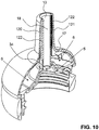
- FIGS. 6 to 10 It is shown how such a teat can be integrated into a teat unit and this can be attached to a suction bottle.
- a suction or milk bottle 4 exemplified.
- Other types and shapes of drinking vessels may also be used with the teat units according to the inventive teaching. Preferably, however, they have a container neck with an external thread.
- the Saugnippelillon consists of the teat 1 and the here two-part Saugnippelverbinder, which comprises a base part 3 and a receiving head 2.
- the base part 3 is preferably made of polypropylene (PP) or a polyamide
- the receiving head 2 made of PP or a polyamide or a combination of PP or a polyamide with silicone, rubber or TPE.
- the base part 3 is dimensionally stable and consists of a rigid material. It consists essentially of a ring body 30 with a circumferential, closed outer shell, which preferably has a sufficient grip to serve as a rotary ring when mounting and removing the teat unit to or from the container 4.
- At least one slot 31 is arranged in the peripheral edge of the annular body 30 in the peripheral edge of the annular body 30 in the peripheral edge of the annular body 30.
- the slot is formed bent according to the radius of the annular body 30.
- the slot 31 extends to the inner wall of the annular body 30.
- the distance between opposite wall regions is equal to or preferably greater than the outer diameter of the thread of the container 4th
- a circumferential outer sealing edge 37 is present, which protrudes upward. This is preferably formed by the uppermost peripheral edge of the base ring 3. Spaced to the outer sealing edge 37, an inner circumferential sealing edge 38 is present, which also protrudes upwards.
- the slot 31 is thus located between the first and the second sealing edge 37, 38.
- this sealing edge 38 is interrupted by at least one ventilation opening 381, which leads to the outside. The way to the outside, for example, lead via a non-tight threaded connection with the milk bottle 4 or extend between the base part 3 and recording head 2.
- an inner truncated cone 35 is integrally formed within the inner sealing edge 38 and in the upper region. Its flanks can be formed straight or curved. It projects beyond the annular body 30 and extends upwards to the receiving head 2.
- the passage opening 34 is preferably in the uppermost region, preferably in the flattened top, arranged. This tip may have a cylindrical shell and extend over the passage opening 34 so as to form an upper sealing edge 340.
- In the interior of this sealing edge 340 is a flat surface 341.
- This base part 3 can be placed on the container neck, but without it already fixed in position relative to it, in particular twist is secured.
- the abutment is an inner bearing surface 39 in the upper region of the base ring 3.
- the receiving head 2 is also annular and preferably rotationally symmetrical and has a central passage opening 22. It basically consists of two areas.
- the lower region is formed by at least one plug-in element 20.
- the plug-in element 30 has on its inside an internal thread 201. Instead of an internal thread and an external thread may be present if the drinking container 4 is provided with a corresponding internal thread.
- the receiving head 2 can be inserted into the base part 3, wherein the plug element 20 engages in the slot 31. Snap-in lugs of the plug element 20 and / or the slot 31 can prevent a subsequent falling out of the receiving head 2 from the base part 3.
- the length of the plug element 20 is dimensioned such that it extends approximately to the lower edge of the base part 3, but this does not protrude.
- a hinge 202 is arranged, which engages in a corresponding recess 300 of the base part 3.
- the plug-in element 20 is designed to be slightly resilient, detachment is facilitated.
- suspension may be provided by suitable choice of the thickness of the male member 20, i. the material thickness can be achieved.
- the two parts can preferably only be separated from one another if they are not screwed onto the container 4.
- the upper portion of the receiving head 2 has peripherally arranged support body 24, which cooperate with the above-described suction nipple 1.
- the peripheral support structure 24 is formed by support wings 240, which are evenly distributed over the circumference and arranged in the peripheral region. They protrude like petals obliquely inward upward. In this example, they each have a substantially rectangular basic shape, with their edges being rounded.
- these support wings 240 are rigid. They can be resilient, non-resilient or barely resilient. They are in particular made in one piece with the rest of the receiving head by injection molding or other suitable manufacturing process.
- the support wings 240 may also be formed of a softer material than that of the plug-in elements 20. Preferably, however, even if they are relatively soft, dimensionally stable. Instead of the petals, for example, completely filled knobs can be used as a support structure.
- a protruding circumferential fastening edge 21 with a peripherally encircling outer sealing surface 210 is present. It is planar and extends approximately perpendicular to the longitudinal center axis of the receiving head.
- the receiving head 2 has in the interior an upwardly projecting towards the suction nipple 1 outer truncated cone 25, in the flattened tip of the passage opening 22 is arranged.
- the uppermost region of the truncated cone 25 is surrounded by a bead, which delimits a peripheral groove 250.
- a valve may be arranged inside the tip of the outer truncated cone 25, a valve may be arranged. This is not mandatory.
- a valve diaphragm 220 is shown inside the tip of the outer truncated cone 25 . It closes the relatively small passage opening 22.
- the main body 10 of the teat 1 is bent as described above with its lower edge inwards, so that the radially inwardly directed flange 11 is formed.
- the suction nipple 1 can be with its base 10 over the support wings 240 of the receiving head 2, wherein the upper part of the receiving head 2 from the nipple 1 is included.
- the flange 11 engages behind the projecting edge between the upper and lower regions of the receiving head 2 and lies flat against the outer sealing surface 210 of the same.
- the teat 1 can thus be attached to the receiving head 2 or partially put over him. Subsequently, the recording head 2 can be inserted into the base part 3. The recording head 2 can be stuck in the base part 3, if this is free but also if it is already on the container neck. Since the base part 3 in the axial direction with respect to the receiving head 3 can still move easily, the teat 1 can optionally be slipped over the former only when plugged recording head 2 and base part 3.
- the outer truncated cone 25 surrounds the inner truncated cone 35, wherein the two through-openings 34, 22 are preferably aligned with one another in the longitudinal central axis.
- the suction opening 13 is in mounted state through the through holes 22, 34 of the receiving head 2 and the base part 3 connected to the container interior, so that the baby through this opening his drink, such as tea, water or milk can drink.
- the surface 341 of the base part 3 forms the valve seat for the membrane 220.
- a circumferential gap 5 arises between the two truncated cones 25, 35, which is formed by the fact that the two truncated cones 25, 35 do not have the same inclination ,
- This intermediate space forms a ventilation chamber 5.
- at least one ventilation or discharge opening 381 leads from this chamber 5 to the outside.
- a support space 6 is formed, which deforms depending on the stress of the nipple 1 by the infant.
- the outer truncated cone 25 protrudes to the mouthpiece 12 and forms a central support body. As a result, the mouthpiece 12 is optimally supported.
- the base part 3 or the receiving head 2 By turning the base part 3 or the receiving head 2 on the container neck, the two threads, external thread and internal thread 201 engage with each other.
- the pickup head 2 runs down the thread along. With him, the base part 3 is pulled down to its lower stop. This means in the embodiments described here that it rests with its upper inner stop surface 39 on the upper edge of the container neck.
- Base part 3 and receiving head 2 are now mounted on the container 4 and secured relative to each other twist.
- the outer sealing surface 370 of the base part 3 is now pressed relative to the outer sealing surface 210 of the receiving head 2. They clamp the flange 11 of the suction nipple 1 and thus ensure a liquid and airtight connection between the nipple 1, receiving head 2 and base part 3.
- a differently shaped lower edge 11 of the teat 1 between the two parts 2, 3 are clamped sealing.
- the base part 3 can be rotated again, so that the rotation between the base part 3 and recording head. 2 solves. Due to the axial displaceability of the base part 3, the flange 11 is released and the teat 1 can be removed from the receiving head 2. Subsequently, the plug connection between receiving head 2 and base part 3 can be released. The three parts can now be cleaned as individual parts and sterilized if necessary.
- the teat according to the invention makes possible an interaction of the palate, tongue and teat which is modeled on natural breastfeeding.
Description
Die Erfindung betrifft einen Saugnippel gemäss Oberbegriff des Patentanspruchs 1.The invention relates to a suction nipple according to the preamble of
Idealerweise trinkt ein Säugling von der Mutterbrust. Es gibt jedoch verschiedene Gründe, weshalb dies nicht immer möglich ist. Seit vielen Jahren wird deshalb versucht, Saugnippel für Babyflaschen zu entwickeln, welche dem Säugling ein möglichst der Natur nachempfundenes Saugen ermöglichen. Der Säugling soll möglichst ohne Verwirrung zwischen Mutterbrust und Saugflasche hin und her wechseln können. Dabei wird unter anderem Wert darauf gelegt, dass der Säugling den Milchfluss nicht ungewollt unterbrechen kann, indem er das Mundstück des Saugnippels zu fest zusammenpresst. In den Anfängen der gezielten Entwicklung von Saugnippeln stand zudem im Vordergrund, dass der Saugnippel keine bleibenden Schäden im Babymund verursacht.Ideally, an infant drinks from the mother's breast. However, there are several reasons why this is not always possible. For many years, therefore, attempts have been made to develop nipples for baby bottles, which allow the infant as possible a nature-inspired sucking. The infant should be able to switch back and forth between mother's breast and feeding bottle without any confusion. Among other things, emphasis is placed on the fact that the infant can not interrupt the flow of milk unintentionally by pressing the mouthpiece of the teat too tightly. In the beginning of the targeted development of teat nipples was also in the foreground that the teat does not cause permanent damage in baby mouth.
Aus diesem Grund lehrt
In
Es ist eine Aufgabe der Erfindung, einen Saugnippel zu schaffen, welcher ein möglichst naturgetreues Saugen ermöglicht.It is an object of the invention to provide a teat which allows a lifelike as possible.
Diese Aufgabe löst ein Saugnippel mit den Merkmalen des Patentanspruchs 1.This object is achieved by a suction nipple with the features of
Untersuchungen während des Stillvorgangs haben gezeigt, dass nicht alleine die Dehnbarkeit des Mundstücks während des Saugvorgangs und das Vermeiden des Verschlusses des Milchkanals wesentliche Elemente sind. Ebenso wichtig ist das Zusammenwirken von Saugnippel, Gaumen und Zunge. Der erfindungsgemässe Saugnippel berücksichtigt das natürliche Zusammenspiel von Gaumen, Zunge und Brustwarze. Da der Saugnippel einen Luftraum oder eine Kammer aufweist, welche sich während des Saugens zyklisch aufbläht, kann der Saugnippel ähnlich wie die Brustwarze der Mutter der Zungen- und/oder Gaumenbewegung des Säuglings folgen und den Mundraum ähnlich wie die Brustwarze der Mutter optimal ausfüllen.Studies during breastfeeding have shown that not only the extensibility of the mouthpiece during the suction process and the avoidance of the closure of the milk duct are essential elements. Equally important is the interaction of teat, palate and tongue. The inventive nipple takes into account the natural interaction of the palate, tongue and nipple. Since the teat has an air space or a chamber which inflates cyclically during suction, the teat similar to the nipple of the mother can follow the tongue and / or palate movement of the infant and optimally fill the mouth similar to the nipple of the mother.
In einer bevorzugten Ausführungsform bläht sich dabei der Luftraum nicht nur in senkrechter Richtung zur Längsachse des Saugnippels auf. Dank seiner dreidimensionalen Vergrösserung wird das Mundstück des Saugnippels verlängert und erstreckt sich bis zum weichen Gaumen des Kindes.In a preferred embodiment, the air space does not only inflate in the direction perpendicular to the longitudinal axis of the suction nipple. Thanks to its three-dimensional enlargement, the mouthpiece of the teat is extended and extends to the soft palate of the child.
Der erfindungsgemässe Saugnippel erlaubt eine möglichst naturgetreue Nachbildung, so dass Saugverwirrung beim Wechseln vom Saugnippel auf die natürliche Mutterbrust vermieden werden kann.The inventive teat nipple allows a lifelike reproduction, so that Saugverwirrung can be avoided when changing from teat to the natural mother's breast.
Der erfindungsgemässe Saugnippel weist einen Grundkörper mit einer Eingangsöffnung und ein Mundstück mit einer Saugöffnung und mit mindestens einem von der Eingangsöffnung zur Saugöffnung verlaufenden Saugkanal auf. Durch den Saugkanal kann der Säugling eine Flüssigkeit, insbesondere Milch, saugen. Das Mundstück weist mindestens eine ausdehnbare Zone auf, welche getrennt vom mindestens einen Saugkanal verläuft und welche bei Gebrauch zwischen Gaumen und Zunge eines Säuglings liegt.The teat according to the invention has a main body with an inlet opening and a mouthpiece with a suction opening and with at least one suction channel extending from the inlet opening to the suction opening. Through the suction channel of the infant suck a liquid, especially milk. The mouthpiece has at least one expandable zone, which runs separately from the at least one suction channel and which lies in use between the palate and the tongue of an infant.
Diese Zone ist so ausgebildet ist, dass sie sich bei einem Unterdruck, welcher durch den Säugling während des Saugens in seinem Mund erzeugt wird, ausdehnt, insbesondere aufbläht.This zone is designed so that it expands, in particular inflates, at a negative pressure which is produced by the infant during its sucking in its mouth.
Diese Ausdehnung ist vorzugsweise reversibel, so dass sich die Zone während des Saugens und nach Massgabe des Saugrhythmus zyklisch ausdehnt und ihr Volumen wieder verkleinert.This expansion is preferably reversible, so that the zone expands cyclically during suction and in accordance with the suction rhythm and reduces its volume again.
Vorzugsweise ist das Mundstück, insbesondere der Saugkanal, biegeweich ausgebildet. Vorzugsweise ist der Saugkanal annähernd gleich weich wie oder sogar weicher ausgebildet als die äussere Wandung des Mundstücks. Diese weiche bzw. biegeweiche Ausbildung ermöglicht eine optimale Anpassung der radialen Nippelform an den Saugvorgang des Säuglings, da das Mundstück der Zungen- und/oder Gaumenbewegung optimal folgen kann. Des weiteren ermöglicht diese Ausbildung, dass sich das Mundstück auch während des Saugens verlängern kann. Vorzugsweise ist auch die Verlängerung des Mundstücks während und nach Massgabe des Saugzyklus reversibel.Preferably, the mouthpiece, in particular the suction channel, formed bendable soft. Preferably, the suction channel is approximately as soft as or even softer than the outer wall of the mouthpiece. This soft or flexurally soft training allows optimal adaptation of the radial nipple shape to the sucking process of the infant, since the mouthpiece of the tongue and / or palate movement can follow optimally. Furthermore, this design allows the mouthpiece to extend even while sucking. Preferably, the extension of the mouthpiece during and after the suction cycle is reversible.
In einer bevorzugten Ausführungsform weist das Mundstück bei Gebrauch eine obere, einem Gaumen eines Säuglings zugewandte Seite und eine untere, einer Zunge des Säuglings zugewandte Seite auf, wobei es auf seiner oberen Seite mindestens doppelwandig mit zwei Wänden ausgeführt ist und die mindestens eine Zone zwischen diesen zwei Wänden angeordnet ist.In a preferred embodiment, the mouthpiece, in use, has an upper side facing an infant's palate and a lower side facing a tongue of the infant, having at least one double walled wall on its upper side and at least one zone between them two walls is arranged.
Vorzugsweise ist diese Zone eine gegenüber dem Grundkörper offene oder geschlossene Kammer oder ein Raum, welche bzw. welcher mit Luft, einem Gas, einer Flüssigkeit oder einem Schaum gefüllt ist. Ist die Kammer mit Schaum gefüllt, so ist dieser entweder selber bei Unterdruck expandierbar oder er weist mit Gas, insbesondere Luft, gefüllte Kammern auf, welche bei Unterdruck expandieren.This zone is preferably a chamber which is open or closed with respect to the main body or a space which is filled with air, a gas, a liquid or a foam. If the chamber is filled with foam, then it is either itself expandable under reduced pressure or it has gas, in particular air, filled chambers which expand under reduced pressure.
Der erfindungsgemässe Saugnippel gemäss einer bevorzugten Ausführungsform weist einen Grundkörper, ein Mundstück mit einer Saugöffnung und mindestens einen vom Grundkörper zur Saugöffnung verlaufenden Saug- oder Milchkanal auf. Das Mundstück weist eine im Umfang geschlossene Aussenwand und eine im Bereich der Saugöffnung an die Aussenwand anschliessende im Umfang geschlossene Innenwand auf, wobei die Innenwand auf ihrer zu ihrer Längsmittelachse hin gerichteten Innenseite den mindestens einen Milchkanal bildet. Erfindungsgemäss verläuft der mindestens eine Luftraum getrennt vom mindestens einen Saugkanal, wobei er Distanzhalter aufweist.The inventive suction nipple according to a preferred embodiment has a base body, a mouthpiece with a suction opening and at least one extending from the base body to the suction opening suction or milk channel. The mouthpiece has an outer wall closed in the circumference and an inner wall adjoining the outer wall in the region of the suction opening and closed on the circumference, wherein the inner wall forms the at least one milk channel on its inner side directed towards its longitudinal center axis. According to the invention, the at least one air space extends separately from the at least one suction channel, wherein it has spacers.
Der erfindungsgemässe Saugnippel berücksichtigt das Zusammenspiel von Gaumen, Zunge und Saugnippel. Er ermöglicht insbesondere, dass der Saugnippel während der Phase des Saugens, in welcher der hintere Bereich der Zunge abgesenkt ist, praktisch mit seiner gesamten oberen Fläche vollständig am Gaumen des Säuglings anliegt. Des Weiteren liegt der Saugnippel während der Phase des Saugens, in welcher der hintere Bereich der Zunge angehoben ist, praktisch mit seiner gesamten unteren Fläche an der Zunge des Säuglings an.The inventive nipple takes into account the interaction of the palate, tongue and teat. In particular, it allows the teat to lie fully against the infant's palate during its sucking phase, in which the posterior region of the tongue is lowered, with virtually its entire upper surface. Furthermore, during the sucking phase, in which the posterior region of the tongue is raised, the teat nipple abuts virtually the entire lower surface of the tongue of the infant.
Ultraschallaufnahmen eines an der Mutterbrust gestillten Babys haben gezeigt, dass das Baby zyklisch zwischen zwei Saugphasen hin und her wechselt. In einer Phase A ist der hintere Bereich der Zunge des Babys angehoben und drückt gegen den harten Gaumen. In einer Phase B ist dieser hintere Zungenbereich abgesenkt. Die Ultraschallaufnahmen haben ferner gezeigt, dass die Brustwarze in die Länge gezogen wird bis kurz vor den Übergang vom harten zum weichen Gaumen. Der Säugling erzeugt im Mund einen Unterdruck, indem er in der Phase B seine Zunge in ihrem hinteren Bereich nach unten bewegt. Die Oberlippe einerseits und entweder die Zunge und/oder die Unterlippe andererseits bilden dabei einen dichtenden Verschluss gegen aussen. Der weiche Gaumen des Babys hilft, den Unterdruck während des Saugens aufrecht zu erhalten. Der weiche Gaumen bildet eine rachenseitige Dichtung, um das Vakuum im Mundraum aufrecht zu erhalten. In der Phase A weist die Brustwarze einen koronaren Querschnitt in der Form einer Ellipse auf, wobei die grosse Halbachse liegend ausgerichtet ist. In der Phase B ist die Brustwarze vom Maximalvakuum vorgespannt und weist einen annähernd runden Querschnitt auf. Durch die zyklische Bewegung der Zunge nach unten und oben verändert sich somit der Durchmesser der Brustwarze in demselben Zyklus. Der koronare Querschnitt wechselt zyklisch seine Form, wobei die Querschnittsfläche in der Phase B im Vergleich zur Phase A eher verringert ist. Diesen Effekt bildet der erfindungsgemässe Saugnippel nun nach.Ultrasound scans of a breast-fed baby have shown that the baby is cyclically switching back and forth between two sucking phases. In a phase A, the back of the baby's tongue is raised and presses against the hard palate. In a phase B, this rear tongue area is lowered. The ultrasound images have also shown that the nipple is stretched to just before the transition from the hard to the soft palate. The infant creates a negative pressure in the mouth by moving its tongue downwards in phase B in phase B. The upper lip on the one hand and either the tongue and / or the lower lip on the other hand form a sealing closure against the outside. The soft palate of the baby helps to maintain the negative pressure during sucking. The soft palate forms a throat-side seal to maintain the vacuum in the oral cavity. In phase A, the nipple has a coronal cross-section in the shape of an ellipse, with the major half-axis aligned. In phase B, the nipple is preloaded by the maximum vacuum and has an approximately round cross-section. The cyclic movement of the tongue up and down thus changes the diameter of the nipple in the same cycle. The coronal cross section cyclically changes its shape, the cross-sectional area in phase B being rather reduced compared to phase A. This effect forms the inventive Teat now after.
Die mindestens eine Luftkammer des Saugnippels, welche vorzugsweise atmosphärischen Druck aufweist, bläht sich bei äusserem Unterdruck auf. Dadurch vergrössert sich der äussere Durchmesser wie die Brustwarze. Die Luftkammer verändert ihr Volumen im gleichen Zyklus, wie das Baby die Zunge anhebt und senkt. Ist mindestens die obere Seite des Saugnippels mit einer derartigen Luftkammer versehen, so ist gewährleistet, dass der Saugnippel während der Phase B gleich wie die Brustwarze am harten Gaumen des Babys anliegt.The at least one air chamber of the suction nipple, which preferably has atmospheric pressure, inflates at an external negative pressure. This enlarges the outer diameter like the nipple. The air chamber changes its volume in the same cycle as the baby raises and lowers the tongue. If at least the upper side of the teat is provided with such an air chamber, it is ensured that the teat during phase B rests like the nipple on the hard palate of the baby.
Der Luftraum, oder im Falle mehrerer Luftkammern mindestens eine dieser Luftkammern, kann gegenüber dem Grundkörper offen ausgebildet sein. Diese Ausführungform ist einfach und somit kostengünstig herstellbar. Mindestens eine oder alle dieser Luftkammern können jedoch auch gegenüber dem Grundkörper geschlossen ausgebildet sein. Diese Ausführungsform gewährleistet, dass auf jeden Fall der Balloneffekt vollständig erzielt wird, d.h. sich die Kammer aufbläst.The air space, or in the case of several air chambers at least one of these air chambers, may be formed open to the main body. This embodiment is simple and therefore inexpensive to produce. However, at least one or all of these air chambers may also be formed closed relative to the main body. This embodiment ensures that in any case the balloon effect is fully achieved, i. the chamber inflates.
In einer bevorzugten Ausführungsform verläuft der mindestens eine Luftraum ringförmig um eine Längsmittelachse des Mundstücks und befindet sich somit auch auf der unteren, der Zunge des Babys zugewandten Seite des Saugnippels.In a preferred embodiment, the at least one air space extends annularly around a longitudinal central axis of the mouthpiece and is therefore also located on the lower, the tongue of the baby facing side of the teat.
Der Luftraum kann sich nur über einen Teil der Länge des Mundstücks erstrecken. Vorzugsweise erstreckt er sich aber über die gesamte Länge. Es ist auch möglich, dass mehrere Lufträume über die Länge des Mundstücks verteilt übereinander angeordnet sind, wobei diese Lufträume vollständig voneinander getrennt sind und keinen gegenseitigen Luftaustausch ermöglichen. Sie können jedoch auch so gestaltet sein, dass ein Luftaustausch möglich ist.The air space may extend only over part of the length of the mouthpiece. Preferably, however, it extends over the entire length. It is also possible that several air spaces are distributed over the length of the mouthpiece arranged one above the other, these air spaces are completely separated from each other and do not allow mutual exchange of air. However, they can also be designed so that an air exchange is possible.
Es können mehrere Milchkanäle vorhanden sein. Vorzugsweise ist jedoch ein einziger Milchkanal vorhanden, welcher koaxial entlang der Längsmittelachse des Mundstücks verläuft.There may be several milk channels. Preferably, however, there is a single milk channel which runs coaxially along the longitudinal central axis of the mouthpiece.
In einer bevorzugten Ausführungsform sind im Luftraum Distanzhalter, beispielsweise Rippen, angeordnet, welche beim Zusammenpressen des Mundstücks diesen Luftraum in einer verkleinerten Form bewahren. Dadurch wird verhindert, dass die Wände des Mundstücks aneinander kleben bleiben und sich der Luftraum beim nächsten Zyklus nicht mehr aufblähen könnte. Vorzugsweise sind die Distanzhalter Vorsprünge, welche an mindestens einer der Wände des Mundstücks angeordnet sind und zum Luftraum hin gerichtet sind. Es können aber auch Rillen sein. Die Vorsprünge können auf gleich bleibender Höhe verlaufen. Vorzugsweise erstreckt sich ihre Längsrichtung jedoch in axialer Richtung. In einer bevorzugten Ausführungsform erstrecken sie sich über annähernd die gesamte Länge des Luftraums.In a preferred embodiment, spacers, for example ribs, are arranged in the air space, which retain this air space in a reduced form when the mouthpiece is compressed. This prevents the walls of the mouthpiece from sticking to one another and the air space from being unable to inflate during the next cycle. Preferably, the spacers are projections which are arranged on at least one of the walls of the mouthpiece and directed towards the air space. But it can also be grooves. The projections can run at a constant height. Preferably, however, its longitudinal direction extends in the axial direction. In a preferred embodiment, they extend over approximately the entire length of the air space.
Die erfindungsgemässe, einfach herstellbare und einfach zu reinigende Ausführungsform weist eine im Umfang geschlossene Aussenwand, eine im Bereich der Saugöffnung an die Aussenwand anschliessende, im Umfang geschlossene Innenwand und einen am freien Ende der Innenwand anschliessenden Flansch auf. Die Innenwand bildet auf ihrer zu ihrer Längsmittelachse hin gerichteten Innenseite den mindestens einen Milchkanal. Der Flansch ist radial von der Innenwand weg nach aussen gerichtet. Er ist beispielsweise in eine Öffnung eines Aufnahmekopfs einer Saugnippeleinheit dichtend einhängbar, um den mindestens einen getrennten Luftraum zwischen Aussenwand und Innenwand zu bilden.The inventive, easy to manufacture and easy-to-clean embodiment has an outer wall closed in the periphery, one in the region of the suction opening to the outer wall subsequent, circumferentially closed inner wall and a subsequent to the free end of the inner wall flange. The inner wall forms on its side directed towards its longitudinal central axis inside the at least one milk channel. The flange is directed radially outwardly away from the inner wall. He is, for example, sealingly suspended in an opening of a receiving head of a Saugnippeleinheit to form the at least one separate air space between the outer wall and inner wall.
Weitere vorteilhafte Ausführungsformen gehen aus den abhängigen Patentansprüchen hervor.Further advantageous embodiments will become apparent from the dependent claims.
Im Folgenden wird der Erfindungsgegenstand anhand von bevorzugten Ausführungsbeispielen, welche in den beiliegenden Zeichnungen dargestellt sind, erläutert. Es zeigen:
Figur 1- eine schematische Darstellung eines Babymunds während des Saugens an einem erfindungsgemässen Saugnippel;
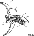
- Figur 2a
- eine schematische Darstellung des erfindungsgemässen Saugnippels und des Gaumens während der Saugphase B, wenn der hintere Bereich der Zunge des Babys abgesenkt ist;
- Figur 2b
- eine weitere Darstellung des Saugnippels in der Saugphase B;
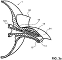
- Figur 3a
- der Saugnippel und der
Gaumengemäss Figur 2 während der Saugphase A, wenn der hintere Bereich der Zunge angehoben ist; - Figur 3b
- eine weitere Darstellung des Saugnippels in der Saugphase A;
Figur 4- eine perspektivische Darstellung eines Längsschnitts durch den erfindungsgemässen Saugnippel;
Figur 5- einen Längsschnitt durch den
Saugnippel gemäss Figur 4 ; Figur 6- eine Seitenansicht einer Saugnippeleinheit mit dem erfindungsgemässen Saugnippel und einer Milchflasche in einer Explosionsdarstellung;
- Figur 7
- einen Längsschnitt durch die Saugnippeleinheit und Milchflasche gemäss
Figur 6 ; - Figur 8
- eine perspektivische Darstellung der Saugnippeleinheit und Milchflasche gemäss
Figur 6 ; Figur 9- eine Längsschnitt durch die Saugnippeleinheit mit montiertem Saugnippel gemäss
Figur 6 und Figur 10- eine perspektivische Darstellung des Längsschnitts gemäss
Figur 9 .
- FIG. 1
- a schematic representation of a baby mouth while sucking on a teat according to the invention;
- FIG. 2a
- a schematic representation of the inventive nipple and the palate during the suction phase B, when the rear portion of the tongue of the baby is lowered;
- FIG. 2b
- a further illustration of the suction nipple in the suction phase B;
- FIG. 3a
- the teat and the palate
FIG. 2 during the suction phase A, when the rear portion of the tongue is raised; - FIG. 3b
- a further illustration of the suction nipple in the suction phase A;
- FIG. 4
- a perspective view of a longitudinal section through the inventive nipple;
- FIG. 5
- a longitudinal section through the teat according to
FIG. 4 ; - FIG. 6
- a side view of a teat unit with the inventive teat and a milk bottle in an exploded view;
- FIG. 7
- a longitudinal section through the teat unit and milk bottle according to
FIG. 6 ; - FIG. 8
- a perspective view of the teat unit and milk bottle according to
FIG. 6 ; - FIG. 9
- a longitudinal section through the teat unit with mounted nipple according
FIG. 6 and - FIG. 10
- a perspective view of the longitudinal section according to
FIG. 9 ,
Ein Mundstück 12 eines erfindungsgemässen Saugnippels 1 befindet sich im Mund 9 des Babys. Der vordere Teil der Zunge 93 und/oder die Unterlippe zum einen und die Oberlippe zum anderen umschliessen den Saugnippel 1 dichtend gegen aussen. Das Mundstück 12 ragt fast bis zum Übergang des harten Gaumens 91 in den weichen Gaumen 92 in den Mund 9 hinein. Der vordere Teil der Zunge 93 drückt von unten gegen das Mundstück 12, wobei der hintere Teil der Zunge 93 abgesenkt ist. Es entsteht im hinteren Bereich ein Hohlraum 94, wodurch ein Unterdruck im Mund 9 erzeugt wird.A
Ein oberer Bereich des Mundstücks 12 bildet eine ausdehnbare Zone 14, welche am harten Gaumen 91 anliegt. Diese Zone 14 ist vorzugsweise eine mit einem Fluid gefüllte Kammer oder ein Luftraum. Im folgenden wird anstelle von Zone von Luftraum gesprochen. Andere Arten von Zonen sind gleichermassen verwirklichbar. Insbesondere kann der Raum anstatt mit Luft mit einem anderen Gas, mit einer Flüssigkeit oder mit einem Schaum gefüllt sein.An upper portion of the
Der Luftraum 14 liegt im Wesentlichen über seine gesamte Länge am harten Gaumen 91 an. Im hier dargestellten Beispiel liegt, da sich die Luftkammer 14 im Wesentlichen über die gesamte Länge des Mundstücks 12 erstreckt, das Mundstück 12 über seine gesamte Länge am harten Gaumen 91 an.The
Der untere Bereich des doppelwandigen Mundstücks 12 ist zusammengepresst, wobei auch hier ein vorderer Luftraum 15 vorhanden ist. Dieser muss jedoch nicht zwingend vorhanden sein. Wie in
Ein im Mundstück 12 verlaufender Milchkanal 18 ist hier praktisch vollständig geschlossen dargestellt. Dies muss nicht zwingend der Fall sein. Der Milchfluss ist jedoch in dieser Situation weitgehend unterbrochen. Eine Saugöffnung des Saugnippels 1 ist mit dem Bezugszeichen 13 versehen.A running in the
Dieselbe Situation ist in den
In den
Beim Saugen am Saugnippel 1 wechselt nun das Baby zwischen den in den
Vorzugsweise ist mindestens auf der Oberseite des Mundstücks 12 mindestens ein oberer Luftraum 14 vorhanden. Vorzugsweise ist jedoch auch auf der Unterseite des Mundstücks 12 mindestens ein unterer Luftraum 15 vorhanden. Auf beiden Seiten können auch mehrere Lufträume vorhanden sein. Der obere und der untere Luftraum 14, 15 können miteinander verbunden sein oder sogar durch denselben Raum gebildet werden, so dass das Mundstück 12 rotationssymmetrisch ausgebildet ist.Preferably, at least on the top of the
Die Lufträume 14, 15 weisen vorzugsweise Atmosphärendruck auf. Sie können offen ausgebildet sein und somit mit der Aussenseite des Saugnippels 1 kommunizieren. Wie in den
Die Lufträume 14, 15 können jedoch auch geschlossen ausgebildet sein. Sie können in diesem Fall auch einen Überdruck gegenüber dem Atmosphärendruck oder einen Unterdruck aufweisen, solange dieser Unterdruck wesentlich kleiner (d.h. näher beim Atmosphärendruck liegend) als der im Mund des Babys erzeugte Unterdruck ist.However, the
Der erfindungsgemässe Saugnippel 1 und insbesondere sein Mundstück 12 mit dem mindestens einen Luftraum 14 können die unterschiedlichsten Formen aufweisen. In den
Die
Das Mundstück 12 ist doppelwandig ausgeführt. Es weist eine im Umfang vollständig umlaufende und geschlossen ausgebildete Aussenwand 120 auf. An das obere Ende dieser Aussenwand 120 schliesst eine Innenwand 121 an, welche vorzugsweise einstückig mit der Aussenwand 120 hergestellt ist. Sie kann jedoch auch verschweisst oder auf andere Weise mit ihr dicht verbunden sein. Die Innenwand 121 ist ebenfalls im Umfang vollständig umlaufend und geschlossen ausgebildet. Sie ragt nach unten Richtung Grundkörper 10, wobei sie sich mindestens über die gesamte Länge der Aussenwand 120 erstreckt. Vorzugsweise ragt sie mit ihrem unteren Ende teilweise in den Grundkörper 10 hinein. Am unteren Ende der Innenwand 121 schliesst ein Flansch 123 an, welcher ebenfalls vorzugsweise einstückig mit dieser hergestellt oder nachträglich mit ihr verbunden ist.The
Grundkörper 10, Aussen- und Innenwand 120, 121 können dieselbe Wandstärke oder unterschiedliche Wandstärken und/oder eine unterschiedliche Dehnbarkeit aufweisen. Die einzelnen Teile 10, 120, 121 können in sich selber variierende Wandstärken oder Dehnbarkeiten aufweisen. Vorzugsweise ist die Innenwand 121 annähernd gleich biegeweich ausgebildet wie die Aussenwand 120. Sie kann auch weicher oder steifer ausgebildet sein als die Aussenwand 120. Sie sollte auf jeden Fall nicht zu einer wesentlichen Versteifung des Mundstücks führen.
Zwischen der Aussenwand 120 und der Innenwand 121 wird ein Luftraum 14 gebildet, welcher den gesamten Milchkanal 18 umgibt, jedoch getrennt von ihm verläuft. Das heisst, es fliesst keine Milch durch den Luftraum 14.Between the
In diesem Luftraum 14 sind mindestens in einem Bereich, vorzugsweise gleichmässig über dem Umfang des Milchkanals 18 verteilt, Distanzhalter angeordnet, welche verhindern, dass bei äusserem Druck die Aussenwand 120 und die Innenwand 121 über ihre gesamte gemeinsame Länge aneinander liegen können. Dadurch weist der Luftraum auch bei äusserem Druck ein minimales Volumen auf, welches nicht gleich Null ist. Zudem bleiben die Aussenwand 120 und die Innenwand 121 auch nach Wegfall des äusseren Drucks nicht aneinander kleben.In this
In diesem Beispiel werden die Distanzhalter durch Rippen 122, 17 gebildet, welche in den Luftraum 14 hineinragen. Sie können entweder an der Innenwand 121 oder an der Aussenwand 120 angeordnet, insbesondere einstückig angeformt sein. In diesem Beispiel sind innere Rippen 122 radial nach aussen vorstehend an der Innenwand 121 und äussere Rippen 17 radial nach innen gerichtet an der Aussenwand 120 angeordnet. Sie verlaufen dabei vorzugsweise über den Umfang verteilt versetzt zueinander, wobei sie gleichmässig über den Umfang verteilt angeordnet sind. Die Rippen 122, 17 verstärken zudem die Wände.In this example, the spacers are formed by
Die Längsrichtung der Rippen verläuft in diesem Beispiel in Richtung der Längsmittelachse des Mundstücks 12 bzw. des Milchkanals 18. Die Rippen lassen sich jedoch auch den Milchkanal 18 umlaufend anordnen, indem sie beispielsweise auf gleich bleibender Höhe umlaufen oder sich spiralförmig abwickeln. Anstelle von Rippen sind auch Noppen, Rillen oder andere Erhebungen und Vertiefungen einsetzbar, welche die plane und glatte Oberfläche der Innenwand 121 und/oder der Aussenwand 120 unterbrechen.The longitudinal direction of the ribs extends in this example in the direction of the longitudinal center axis of the
In den
Die Saugnippeleinheit besteht aus dem Saugnippel 1 und dem hier zweiteiligen Saugnippelverbinder, welcher ein Basisteil 3 und einen Aufnahmekopf 2 umfasst. Das Basisteil 3 besteht vorzugsweise aus Polypropylen (PP) oder einem Polyamid, der Aufnahmekopf 2 aus PP oder einem Polyamid bzw. einer Kombination von PP oder einem Polyamid mit Silikon, Kautschuk oder TPE.The Saugnippeleinheit consists of the
Das Basisteil 3 ist formstabil ausgebildet und besteht aus einem steifen Material. Es besteht im Wesentlichen aus einem Ringkörper 30 mit einem umlaufenden, geschlossenen äusseren Mantel, welcher vorzugsweise eine genügende Griffigkeit aufweist, um als Drehring beim Montieren und Entfernen der Saugnippeleinheit auf den bzw. vom Behälter 4 zu dienen.The
Im umlaufenden Rand des Ringkörpers 30 ist mindestens ein Schlitz 31 angeordnet. Der Schlitz ist entsprechend dem Radius des Ringkörpers 30 gebogen ausgebildet. Der Schlitz 31 erstreckt sich bis zur Innenwandung des Ringkörpers 30. Der Abstand zwischen gegenüberliegenden Wandbereichen (durch den Mittelpunkt des Ringkörpers 30 gemessen) ist gleich oder vorzugsweise grösser als der Aussendurchmesser des Gewindes des Behälters 4.In the peripheral edge of the
Auf der dem Behälterhals abgewandten Oberseite des Basisrings 3 ist eine umlaufende äussere Dichtkante 37 vorhanden, welche nach oben vorsteht. Diese ist vorzugsweise durch den obersten Umfangsrand des Basisrings 3 gebildet. Beabstandet zur äusseren Dichtkante 37 ist eine innere umlaufende Dichtkante 38 vorhanden, welche ebenfalls nach oben vorsteht. Der Schlitz 31 befindet sich somit zwischen der ersten und der zweiten Dichtkante 37, 38. Vorzugsweise ist diese Dichtkante 38 von mindestens einer Belüftungsöffnung 381 unterbrochen, welche nach aussen führt. Der Weg nach aussen kann beispielsweise über eine nicht dichte Gewindeverbindung mit der Milchflasche 4 führen oder zwischen Basisteil 3 und Aufnahmekopf 2 verlaufen.On the side facing away from the container neck top of the
Im Basisteil 3 ist innerhalb der inneren Dichtkante 38 und im oberen Bereich ein innerer Kegelstumpf 35 angeformt. Seine Flanken können geradlinig oder gebogen ausgebildet sein. Er überragt den Ringkörper 30 und erstreckt sich nach oben zum Aufnahmekopf 2 hin. Die Durchgangsöffnung 34 ist vorzugsweise im obersten Bereich, vorzugsweise in der abgeflachten Spitze, angeordnet. Diese Spitze kann einen zylinderförmigen Mantel aufweisen und sich über die Durchgangsöffnung 34 erstrecken, so dass sie eine obere Dichtkante 340 bildet. Im Innern dieser Dichtkante 340 befindet sich eine plane Fläche 341. Im unteren Bereich des inneren Kegelstumpfes 35 und der inneren Dichtkante 38 angrenzend ist eine umlaufende innere Dichtfläche 380 vorhanden. Sie verläuft vorzugsweise senkrecht zur Längsmittelachse des Basisteils 3.In the
Dieses Basisteil 3 lässt sich auf den Behälterhals aufsetzen, ohne dass es jedoch bereits relativ zu ihm lagefixiert, insbesondere verdreh gesichert ist. Dabei ist ein unterer Anschlag 39 vorhanden, welcher begrenzt, wie weit der Behälterhals das Basisteil 3 durchsetzen kann, d.h. wie weit das Basisteil 3 auf dem Behälterhals nach unten rutschen kann. In den hier dargestellten Beispielen ist der Anschlag eine innere Auflagefläche 39 im oberen Bereich des Basisrings 3. Andere Arten von Anschlägen 39, wie beispielsweise vorstehende Nasen oder Rippen, sind auch möglich.This
Der Aufnahmekopf 2 ist ebenfalls ringförmig und vorzugsweise rotationssymmetrisch ausgebildet und weist eine zentrale Durchgangsöffnung 22 auf. Er besteht im Wesentlichen aus zwei Bereichen. Der untere Bereich wird durch mindestens ein Steckelement 20 gebildet. Das Steckelement 30 weist auf seiner Innenseite ein Innengewinde 201 auf. Anstelle eines Innengewindes kann auch ein Aussengewinde vorhanden sein, falls der Trinkbehälter 4 mit einem entsprechenden Innengewinde versehen ist.The receiving
Der Aufnahmekopf 2 lässt sich in das Basisteil 3 einstecken, wobei das Steckelement 20 in den Schlitz 31 eingreift. Einrastnasen des Steckelements 20 und/oder des Schlitzes 31 können ein nachträgliches Herausfallen des Aufnahmekopfes 2 aus dem Basisteil 3 verhindern. Vorzugsweise ist die Länge des Steckelements 20 so bemessen, dass es sich annähernd bis zum unteren Rand des Basisteils 3 erstreckt, dieses jedoch nicht überragt.The receiving
An der dem Steckelement 20 diametral gegenüberliegenden Seite des Aufnahmekopfes 2 ist ein Scharnier 202 angeordnet, welches in eine entsprechende Ausnehmung 300 des Basisteils 3 eingreift. Somit ist eine lösbare Steckverbindung vorhanden, ohne dass Aufnahmekopf 2 und Basisteil 3 vollständig voneinander getrennt werden müssen. Sie können gemeinsam, aber in offener Stellung gereinigt werden.At the plug-in
Durch leichtes Auseinanderziehen von Aufnahmekopf 2 und Basisteil 3 in Richtung von derer gemeinsamen Längsmittelsachse lässt sich jedoch der Widerstand von Einrastrippen überwinden und diese aneinander vorbei bewegen. Ist das Steckelement 20 leicht federnd ausgebildet, so wird das Loslösen erleichtert. Eine Federung kann beispielsweise durch geeignete Wahl der Dicke des Steckelements 20, d.h. der Materialstärke, erzielt werden. Die zwei Teile können jedoch vorzugsweise nur voneinander getrennt werden, wenn sie nicht auf dem Behälter 4 aufgeschraubt sind.By slightly pulling apart of the receiving
Der obere Bereich des Aufnahmekopfes 2 weist peripher angeordnete Stützkörper 24 auf, welche mit dem oben beschriebenen Saugnippel 1 zusammenwirken. In diesem Beispiel ist die periphere Stützstruktur 24 durch Stützflügel 240 gebildet, welche über den Umfang gleichmässig verteilt und im peripheren Bereich angeordnet sind. Sie ragen wie Blütenblätter schräg nach innen gerichtet nach oben. In diesem Beispiel weisen sie jeweils eine im Wesentlichen rechteckige Grundform auf, wobei ihre Kanten abgerundet sind. Vorzugsweise sind diese Stützflügel 240 steif ausgebildet. Sie können federnd, nicht federnd oder nur kaum federnd ausgebildet sein. Sie sind insbesondere einstückig mit dem restlichen Aufnahmekopf im Spritzgussverfahren oder einem anderen geeigneten Herstellungsverfahren gefertigt. Die Stützflügel 240 können jedoch auch aus einem weicheren Material als dasjenige der Steckelemente 20 gebildet sein. Vorzugsweise sind sie jedoch, selbst wenn sie relativ weich ausgebildet sind, formstabil. Anstelle der Blütenblätter lassen sich beispielsweise auch vollständig ausgefüllte Noppen als Stützstruktur einsetzen.The upper portion of the receiving
Unterhalb der Stützflügel 240, d.h. im Übergangsbereich vom oberen zum unteren Teil des Aufnahmekopfes 2 ist auf der Unterseite, welche dem Basisteil 3 und dem Behälter 4 zugewandt ist, eine vorstehende umlaufende Befestigungskante 21 mit einer peripher umlaufenden äusseren Dichtfläche 210 vorhanden. Sie ist plan ausgebildet und verläuft annähernd senkrecht zur Längsmittelachse des Aufnahmekopfes 2.Below the
Der Aufnahmekopf 2 weist im Innern einen nach oben, zum Saugnippel 1 hin ragenden äusseren Kegelstumpf 25 auf, in dessen abgeflachter Spitze die Durchgangsöffnung 22 angeordnet ist. Der oberste Bereich des Kegelstumpfes 25 ist von einem Wulst umgeben, welcher eine umlaufende Nut 250 begrenzt.The receiving
Im Innern der Spitze des äusseren Kegelstumpfes 25 kann ein Ventil angeordnet sein. Dies ist nicht zwingend notwendig. Im dargestellten Beispiel ist eine Ventilmembran 220 dargestellt. Sie verschliesst die relativ kleine Durchgangsöffnung 22.Inside the tip of the outer
Der Grundkörper 10 des Saugnippels 1 ist wie oben beschrieben mit seinem unteren Rand nach innen gebogen, so dass der radial nach innen gerichtete Flansch 11 entsteht. Der Saugnippel 1 lässt sich mit seinem Grundkörper 10 über die Stützflügel 240 des Aufnahmekopfes 2 stülpen, wobei der obere Teil des Aufnahmekopfes 2 vom Saugnippel 1 umfasst ist. Der Flansch 11 hintergreift die vorstehende Kante zwischen oberem und unterem Bereich des Aufnahmekopfes 2 und liegt flach an der äusseren Dichtfläche 210 desselben an.The
Der Saugnippel 1 lässt sich somit auf den Aufnahmekopf 2 aufstecken bzw. teilweise über ihn stülpen. Anschliessend lässt sich der Aufnahmekopf 2 in das Basisteil 3 einstecken. Der Aufnahmekopf 2 lässt sich in das Basisteil 3 stecken, wenn dieses frei ist aber auch, wenn es sich bereits auf dem Behälterhals befindet. Da sich das Basisteil 3 in axialer Richtung bezüglich des Aufnahmekopfes 3 noch leicht verschieben lässt, kann der Saugnippel 1 wahlweise auch erst bei zusammengestecktem Aufnahmekopf 2 und Basisteil 3 über ersteren gestülpt werden.The
Wird nun der Saugnippel 1 über den Aufnahmekopf 2 gestülpt, so hintergreift sein radial nach aussen vorstehender und umlaufend ausgebildeter Flansch 123 die Öffnung 22 des Aufnahmekopfes 2 und stellt eine flüssigkeitsdichte Verbindung her. Dieses Einhaken des Flansches 123 ist in den
Wird der Aufnahmekopf 2 in das Basisteil 3 eingesteckt, so umgibt der äussere Kegelstumpf 25 den inneren Kegelstumpf 35, wobei die zwei Durchgangsöffnungen 34, 22 vorzugsweise miteinander in der Längsmittelachse fluchten. Die Saugöffnung 13 ist im montierten Zustand über die Durchgangsöffnungen 22, 34 des Aufnahmekopfes 2 und des Basisteils 3 mit dem Behälterinnenraum verbunden, so dass das Baby durch diese Öffnung sein Getränk, z.B. Tee, Wasser oder Milch, trinken kann.If the receiving
Falls eine Ventilmembran vorhanden ist, so bildet die Fläche 341 des Basisteils 3 den Ventilsitz für die Membran 220. Ein umlaufender Zwischenraum 5 zwischen den zwei Kegelstümpfen 25, 35 entsteht, welcher dadurch gebildet ist, dass die zwei Kegelstümpfe 25, 35 nicht dieselbe Neigung aufweisen. Dieser Zwischenraum bildet eine Belüftungskammer 5. Vorzugsweise führt mindestens eine Belüftungs- oder Entlastungsöffnung 381 von dieser Kammer 5 nach aussen.If a valve membrane is present, then the
Zwischen Saugnippel 1 und Aufnahmekopf 2 wird ein Stützraum 6 gebildet, welcher sich je nach Beanspruchung des Saugnippels 1 durch den Säugling verformt. Der äussere Kegelstumpf 25 ragt bis zum Mundstück 12 und bildet einen zentralen Stützkörper. Dadurch ist das Mundstück 12 optimal abgestützt.Between
Durch Drehen des Basisteils 3 oder des Aufnahmekopfes 2 auf dem Behälterhals greifen die zwei Gewinde, Aussengewinde und Innengewinde 201, ineinander. Der Aufnahmekopf 2 läuft dem Gewinde entlang nach unten. Mit ihm wird das Basisteil 3 hinuntergezogen bis zu seinem unteren Anschlag. Dies bedeutet in den hier beschriebenen Ausführungsformen, dass er mit seiner oberen inneren Anschlagfläche 39 auf der Oberkante des Behälterhalses aufliegt. Basisteil 3 und Aufnahmekopf 2 sind nun auf dem Behälter 4 befestigt und relativ zueinander verdreh gesichert. Dadurch wird nun die äussere Dichtfläche 370 des Basisteils 3 relativ zur äusseren Dichtfläche 210 des Aufnahmekopfes 2 gedrückt. Sie klemmen dabei den Flansch 11 des Saugnippels 1 ein und sorgen somit für eine flüssigkeits- und luftdichte Verbindung zwischen Saugnippel 1, Aufnahmekopf 2 und Basisteil 3. Je nach Ausgestaltung kann auch ein anders geformter unterer Rand 11 des Saugnippels 1 zwischen den zwei Teilen 2, 3 dichtend eingeklemmt werden.By turning the
Wird die Flasche 4 nicht mehr gebraucht, so kann das Basisteil 3 wieder gedreht werden, so dass sich auch die Verdrehsicherung zwischen Basisteil 3 und Aufnahmekopf 2 löst. Durch die axiale Verschiebbarkeit des Basisteils 3 wird der Flansch 11 freigegeben und der Saugnippel 1 lässt sich vom Aufnahmekopf 2 entfernen. Anschliessend lässt sich die Steckverbindung zwischen Aufnahmekopf 2 und Basisteil 3 lösen. Die drei Teile lassen sich nun als Einzelteile reinigen und gegebenenfalls sterilisieren.If the
Der erfindungsgemässe Saugnippel ermöglicht ein dem natürlichen Stillen nachempfundenes Zusammenspiel von Gaumen, Zunge und Saugnippel.The teat according to the invention makes possible an interaction of the palate, tongue and teat which is modeled on natural breastfeeding.
- 11
-
Saugnippel 10 Grundkörper
Suction nipple 10 basic body - 110110
- Befestigungsflanschmounting flange
- 1212
- Mundstückmouthpiece
- 120120
- Aussenwandouter wall
- 121121
- Innenwandinner wall
- 122122
- innere Rippeinner rib
- 123123
- Flanschflange
- 1313
- Saugöffnungsuction opening
- 1414
- oberer Luftraumupper airspace
- 1515
- unterer Luftraumlower airspace
- 1717
- äussere Rippeouter rib
- 1818
- Milchkanalmilk duct
- 22
- AufnahmekopfUp head
- 2020
- Steckelementeplug-in elements
- 201201
- Innengewindeinner thread
- 202202
- Scharnierhinge
- 2121
- Befestigungskanteattachment edge
- 210210
- äussere Dichtflächeouter sealing surface
- 2222
- DurchgangsöffnungThrough opening
- 220220
- Ventilmembranvalve membrane
- 2424
- periphere Stützstrukturperipheral support structure
- 240240
- Stützflügelsupport wings
- 2525
- äusserer Kegelstumpfouter truncated cone
- 33
- Basisteilbase
- 3030
- Ringkörperring body
- 300300
- Ausnehmungrecess
- 3131
- Schlitzslot
- 3434
- DurchgangsöffnungThrough opening
- 341341
- plane Flächeplane surface
- 3535
- innerer Kegelstumpfinner truncated cone
- 3737
- äussere Dichtkanteouter sealing edge
- 3838
- innere Dichtkanteinner sealing edge
- 381381
- Belüftungsöffnungventilation opening
- 3939
- unterer Anschlagbottom stop
- 44
- Behältercontainer
- 55
- Belüftungskammeraeration chamber
- 66
- Stützraumsupport space
- 99
- Mund des BabysMouth of the baby
- 9090
- Oberlippeupper lip
- 9191
- harter GaumenHard palate
- 9292
- weicher Gaumensoft palate
- 9393
- Zungetongue
- 9494
- Vakuumkammervacuum chamber
Claims (13)
- Teat having a main body (10) with an inlet opening, a mouthpiece (12) with a suction opening (13), and at least one suction channel (18), wherein the mouthpiece (12) has at least one extensible zone (14) which extends separately from the at least one suction channel (18) and which, during use, lies between the palate and tongue of a baby, and wherein this zone (14) is designed in such a way that it expands in the presence of an underpressure generated in the baby's mouth during sucking, characterized in that the mouthpiece (12) has a peripherally closed outer wall (120), a peripherally closed inner wall (121) adjoining the outer wall (120) in the area of the suction opening (13), and a flange (123) adjoining the free end of the inner wall (121), wherein the inner wall (121), on its inner face directed towards its longitudinal centre axis, forms the at least one suction channel (18), and wherein the flange (123) is oriented radially outwards from the inner wall (121), such that it can be hinged sealingly into an opening (22) of a receiving head (2) of a teat unit.
- Teat according to Claim 1, wherein the mouthpiece (12), in particular the suction channel (18), is flexible.
- Teat according to one of Claims 1 and 2, wherein the mouthpiece (12), during use, has an upper side directed towards a palate of a baby, and a lower side directed towards the baby's tongue, and wherein the mouthpiece (12) is designed, on its upper side, at least double-walled with two walls, and the at least one zone (14) is arranged between these two walls.
- Teat according to one of Claims 1 to 3, wherein the zone is a chamber which is open or closed with respect to the main body (1) and which is filled with air, a gas, a liquid or a foam.
- Teat according to one of Claims 1 to 4, wherein the suction channel (18) extends coaxially along a longitudinal centre axis of the mouthpiece (12).
- Teat according to one of Claims 1 to 5, wherein the at least one zone (14) extends in a ring shape about a or the longitudinal centre axis of the mouthpiece (12).
- Teat according to one of Claims 1 to 6, wherein the zone (14) contains spacers (122, 17) which, when the mouthpiece (12) is pressed together, preserve this zone (14) with a reduced volume.
- Teat according to Claim 7, wherein these spacers (122, 17) are projections that are arranged on at least one of the walls (120, 121) of the mouthpiece (12) and are oriented towards the zone (14).
- Teat according to one of Claims 1 to 8, wherein the at least one zone (14) extends in the axial direction of the teat (1) along almost the entire length of the mouthpiece (12).
- Teat according to Claim 1, wherein the inner wall (121) extends along at least the entire length of the outer wall (120) of the mouthpiece (12).
- Teat according to one of Claims 1 to 10, wherein the inner wall (121) is longer than the mouthpiece (12) and extends into the main body (10).
- Teat according to one of claims 1 to 11, wherein the zone (14) extends along the entire length of the mouthpiece (12).
- Teat according to one of claims 1 to 12, wherein the inner wall (121) is formed like a hollow cylinder which inner diameter corresponds to the suction opening (13).
Priority Applications (1)
| Application Number | Priority Date | Filing Date | Title |
|---|---|---|---|
| PL09761224T PL2285338T3 (en) | 2008-06-12 | 2009-02-06 | Suction teat |
Applications Claiming Priority (2)
| Application Number | Priority Date | Filing Date | Title |
|---|---|---|---|
| CH8972008 | 2008-06-12 | ||
| PCT/CH2009/000048 WO2009149566A1 (en) | 2008-06-12 | 2009-02-06 | Suction teat |
Publications (2)
| Publication Number | Publication Date |
|---|---|
| EP2285338A1 EP2285338A1 (en) | 2011-02-23 |
| EP2285338B1 true EP2285338B1 (en) | 2016-12-21 |
Family
ID=40580923
Family Applications (4)
| Application Number | Title | Priority Date | Filing Date |
|---|---|---|---|
| EP09761224.6A Active EP2285338B1 (en) | 2008-06-12 | 2009-02-06 | Suction teat |
| EP14176567.7A Active EP2808007B1 (en) | 2008-06-12 | 2009-06-09 | Teat unit |
| EP09761234.5A Active EP2293759B1 (en) | 2008-06-12 | 2009-06-09 | Suction teat unit |
| EP09761233.7A Active EP2293758B1 (en) | 2008-06-12 | 2009-06-09 | Suction teat unit |
Family Applications After (3)
| Application Number | Title | Priority Date | Filing Date |
|---|---|---|---|
| EP14176567.7A Active EP2808007B1 (en) | 2008-06-12 | 2009-06-09 | Teat unit |
| EP09761234.5A Active EP2293759B1 (en) | 2008-06-12 | 2009-06-09 | Suction teat unit |
| EP09761233.7A Active EP2293758B1 (en) | 2008-06-12 | 2009-06-09 | Suction teat unit |
Country Status (18)
| Country | Link |
|---|---|
| US (6) | US8616391B2 (en) |
| EP (4) | EP2285338B1 (en) |
| JP (4) | JP5395898B2 (en) |
| KR (4) | KR101644420B1 (en) |
| CN (3) | CN102065820B (en) |
| AU (3) | AU2009257161B2 (en) |
| BR (2) | BRPI0909882B8 (en) |
| CA (2) | CA2726466A1 (en) |
| CH (1) | CH698956A1 (en) |
| ES (2) | ES2661900T3 (en) |
| HK (2) | HK1153121A1 (en) |
| IL (1) | IL209905A (en) |
| MX (2) | MX2010013457A (en) |
| MY (2) | MY174344A (en) |
| PL (4) | PL2285338T3 (en) |
| RU (2) | RU2504358C2 (en) |
| TW (5) | TW200950771A (en) |
| WO (3) | WO2009149566A1 (en) |
Families Citing this family (30)
| Publication number | Priority date | Publication date | Assignee | Title |
|---|---|---|---|---|
| WO2009116008A2 (en) * | 2008-03-20 | 2009-09-24 | David Elad | Nursing bottle feeding nipple |
| USD617508S1 (en) * | 2009-02-12 | 2010-06-08 | West Agro Inc. | Animal feeding nipple |
| USD617057S1 (en) * | 2009-02-12 | 2010-06-01 | West Agro Inc. | Animal feeding nipple |
| US8371464B2 (en) | 2010-10-27 | 2013-02-12 | Medela Holding Ag | Container with adjustable date indicium |
| CH704758A1 (en) * | 2011-03-29 | 2012-10-15 | Medela Holding Ag | Teat. |
| US8689988B2 (en) * | 2012-05-07 | 2014-04-08 | Tao Xu | Bottle cap having removal tracking indicia |
| US8678228B2 (en) * | 2012-06-28 | 2014-03-25 | Zak Designs, Inc. | Liquid metering assembly |
| US9789988B2 (en) * | 2013-12-16 | 2017-10-17 | Kiley Steven Wilson | Squeezable leak proof feeding bottle |
| US11235900B2 (en) | 2013-12-16 | 2022-02-01 | Kiley Steven Wilson | Flowable food feeding device |
| USD794781S1 (en) | 2015-04-13 | 2017-08-15 | Medela Holding Ag | Valve component for a breastmilk collection system |
| USD776803S1 (en) | 2015-04-13 | 2017-01-17 | Medela Holding Ag | Breast shield connector for breast pump |
| US9662275B2 (en) * | 2015-07-02 | 2017-05-30 | Sue S. Lee | Oral devices |
| RU170367U1 (en) * | 2016-06-08 | 2017-04-24 | Виталий Владимирович Веселов | NOZZLE ON THE FEEDING CONTAINER |
| US9913780B2 (en) * | 2016-07-21 | 2018-03-13 | Carr Lane Quackenbush | Bite-safe artificial teat |
| USD831201S1 (en) | 2016-08-29 | 2018-10-16 | Medela Holding Ag | Safety valve component for a breastmilk collection system |
| GB2560342A (en) * | 2017-03-08 | 2018-09-12 | Product4 Ltd | Valve |
| EP3372218A1 (en) * | 2017-03-09 | 2018-09-12 | Koninklijke Philips N.V. | Feeding bottle device |
| EP3372219A1 (en) * | 2017-03-09 | 2018-09-12 | Koninklijke Philips N.V. | Partitioning component for a feeding bottle device and feeding bottle device |
| USD846394S1 (en) * | 2017-08-28 | 2019-04-23 | Owens-Brockway Glass Container Inc. | Container |
| US20190117518A1 (en) * | 2017-10-23 | 2019-04-25 | Khoa Tho Le | Air-free, flow-control feeding bottle |
| EP3494953A1 (en) * | 2017-12-08 | 2019-06-12 | Koninklijke Philips N.V. | Teat for use with a container for containing a fluid |
| CN108357775B (en) * | 2018-01-26 | 2024-02-09 | 惠州市凯瑞科技有限公司 | Non-screw eye-splice type container cover |
| JP6640282B2 (en) * | 2018-06-08 | 2020-02-05 | ピジョン株式会社 | Electric breast pump, control method of electric breast pump, and control program of electric breast pump |
| US10932991B2 (en) * | 2018-08-31 | 2021-03-02 | Wong Hau Plastic Works & Trading Co., Ltd. | Feeding bottle |
| US20200077623A1 (en) * | 2018-09-10 | 2020-03-12 | Bertrand Dumont | Nipple System for Delivering Fluid to an Animal |
| CN109549855B (en) * | 2019-01-22 | 2021-06-04 | 郁峦 | Paediatrics digestion is infected nursing and is used medicine feeding device |
| GB2586819A (en) * | 2019-09-04 | 2021-03-10 | Tarsia Antonio | A teat |
| EP3878425A1 (en) * | 2020-03-13 | 2021-09-15 | Koninklijke Philips N.V. | Arrangement for a feeding bottle |
| EP3878426A1 (en) * | 2020-03-13 | 2021-09-15 | Koninklijke Philips N.V. | Internal element for a feeding bottle |
| CN114312149A (en) * | 2022-01-26 | 2022-04-12 | 张宪法 | Multi-volume tire inner tube and tire |
Citations (1)
| Publication number | Priority date | Publication date | Assignee | Title |
|---|---|---|---|---|
| US5101991A (en) * | 1988-12-15 | 1992-04-07 | Jex Company, Limited | Nipple for nursing bottle |
Family Cites Families (89)
| Publication number | Priority date | Publication date | Assignee | Title |
|---|---|---|---|---|
| US2734665A (en) * | 1956-02-14 | Device for discharging liquids from | ||
| DE507836C (en) * | 1930-09-20 | Gustav Bermann | Child feeding bottle with valve device | |
| US633343A (en) * | 1899-01-24 | 1899-09-19 | William W R Hanley | Nipple. |
| US689987A (en) * | 1901-06-17 | 1901-12-31 | David Pick | Nursing-nipple. |
| US981072A (en) * | 1909-09-28 | 1911-01-10 | William More Decker | Nursing-nipple. |
| GB191307179A (en) * | 1913-03-26 | 1913-12-04 | Cyril James Mansfield | Improvements in Teats for Feeding Bottles. |
| US1605427A (en) | 1923-10-16 | 1926-11-02 | Anna M Delmas | Nursing nipple |
| US1569693A (en) * | 1924-11-07 | 1926-01-12 | Llewellyn C Young | Nursing nipple |
| US1656157A (en) * | 1926-03-27 | 1928-01-17 | Josephine L Correnti | Nipple for nursing bottles |
| GB347368A (en) * | 1930-02-24 | 1931-04-30 | Leslie Reader | Improvements in or relating to teats for feeding bottles and the like |
| US1904710A (en) * | 1931-08-19 | 1933-04-18 | Barkan Irving | Nipple |
| BE381523A (en) | 1932-04-30 | |||
| US1937278A (en) * | 1932-05-23 | 1933-11-28 | Walter G Kleine | Vent for nursing bottles |
| US2133411A (en) * | 1934-02-27 | 1938-10-18 | Zohe Ludwig Alvine | Baby nurser |
| US2039373A (en) * | 1934-12-08 | 1936-05-05 | Wittmann Marie | Nipple for nursing bottles |
| US2584359A (en) | 1947-10-03 | 1952-02-05 | Lawrence D Miles | Nipple and dispensing device |
| US2597483A (en) * | 1949-10-19 | 1952-05-20 | Joseph Stell | Nipple valve construction |
| US2661001A (en) * | 1951-07-09 | 1953-12-01 | Alstadt Benjamin | Infant feeding means |
| US2769665A (en) * | 1954-02-15 | 1956-11-06 | Scovill Manufacturing Co | Oscillating sprinkler |
| US2760665A (en) * | 1955-05-06 | 1956-08-28 | Raymond O Zenker | Reversible container cap |
| US2812764A (en) * | 1955-12-12 | 1957-11-12 | Crisp Lonnie Ray | Nursing bottle and nipple construction |
| US2774500A (en) * | 1956-01-18 | 1956-12-18 | Deno J Budiani | Infant nursing device |
| US2987209A (en) * | 1957-01-02 | 1961-06-06 | Leonard Royal | Nursing bottle |
| GB934534A (en) * | 1960-06-23 | 1963-08-21 | Shozaburo Yanase | Improvements in teats for feeding-bottles and the like |
| US3266910A (en) * | 1963-06-12 | 1966-08-16 | Owens Illinois Glass Co | Liquid nourishment dispensing package |
| US3207349A (en) * | 1963-12-18 | 1965-09-21 | George B Rabe | Nursing bottle |
| US3220588A (en) * | 1964-09-17 | 1965-11-30 | Lipari Michael | Compartmental dispensing receptacle with accessories |
| US3339771A (en) * | 1967-05-17 | 1967-09-05 | Ballin Gene | Infant feeding container and cap assembly |
| GB1216385A (en) * | 1967-07-26 | 1970-12-23 | Michael Caesar Ritsi | Liquid or solids bottle feeder |
| US3650270A (en) * | 1970-02-18 | 1972-03-21 | West Co | Nipple-retaining ring assembly |
| JPS6028440Y2 (en) * | 1979-07-26 | 1985-08-28 | ピジョン株式会社 | Outflow/inflow control mechanism for baby bottles |
| JPS5623138A (en) | 1979-07-31 | 1981-03-04 | Toshiba Mach Co Ltd | Apparatus for carrying out thin plate |
| DE3336612A1 (en) | 1983-10-07 | 1985-04-25 | Milupa Ag, 6382 Friedrichsdorf | OPENING AND REMOVAL CAP |
| US4548157A (en) * | 1984-02-10 | 1985-10-22 | Timothy L. Chrisman | Sanitary scheduling device for dispenser closures |
| GB2169210B (en) * | 1984-12-17 | 1989-01-05 | Mandy Nicola Haberman | Baby's feeding apparatus |
| GB8503140D0 (en) * | 1985-02-07 | 1985-03-13 | Wyeth John & Brother Ltd | Teat unit |
| CA1271165A (en) * | 1986-03-11 | 1990-07-03 | Jackel International Pty. Ltd. | Drinking cup |
| US4867324A (en) * | 1988-06-03 | 1989-09-19 | John Rogosich | Nursing attachment for disposable beverage containers |
| AU625111B2 (en) * | 1989-02-20 | 1992-07-02 | Otsuka Pharmaceutical Co., Ltd. | Nipple for a nursing bottle |
| US5747083A (en) * | 1990-07-20 | 1998-05-05 | Raymond; Jean-Louis | Device of the feeding-bottle type |
| US5295597A (en) * | 1993-01-21 | 1994-03-22 | Green Richard D | Infant's bottle with valved cap |
| KR960002845Y1 (en) * | 1993-06-07 | 1996-04-09 | 박경옥 | Milk bottle for a baby |
| US5553726A (en) | 1993-11-08 | 1996-09-10 | Park; Ki H. | Dripless feeder nipple system with detachable valve |
| GB2297317B (en) * | 1995-01-30 | 1998-04-22 | Chen Fu Hsiang | A solution feeder with a nipple |
| AUPN439595A0 (en) | 1995-07-25 | 1995-08-17 | Jott Australia Pty. Ltd. | Nursing teat and teat and bottle combination |
| US5758786A (en) * | 1995-11-13 | 1998-06-02 | John; Nigel H. | Multi-compartment baby bottle |
| US5791503A (en) | 1996-02-05 | 1998-08-11 | Lyons; Richard A. | Nursing bottle with anti-air ingestion valve |
| US5897007A (en) * | 1996-05-13 | 1999-04-27 | Schein; Douglas | Nursing bottle |
| US5704505A (en) * | 1996-08-05 | 1998-01-06 | Singh; Hemchandre | Infant bottle feeding system |
| US6045254A (en) * | 1996-12-26 | 2000-04-04 | M.L.I.S. Projects Ltd. | Container having two or more compartments |
| US6161710A (en) * | 1997-11-03 | 2000-12-19 | Dieringer; Mary F. | Natural nipple baby feeding apparatus |
| KR100620464B1 (en) * | 1998-02-21 | 2006-09-05 | 스테리바틀 리미티드 | Feed bottles for a babies |
| US6112919A (en) * | 1998-07-13 | 2000-09-05 | Ho; Shu-E | Leakage preventive device for milk bottles or the like |
| US6126679A (en) * | 1999-04-12 | 2000-10-03 | Botts; Lynne Marie | Nipple for use with liquid and medicine dispensing bottle |
| US20020063103A1 (en) * | 1999-12-13 | 2002-05-30 | Kathleen Kiernan | Nipple for nursing bottle |
| CN2418872Y (en) * | 2000-03-24 | 2001-02-14 | 戴利收 | Automatic flow rate adjustable teat |
| US6354449B1 (en) * | 2000-05-31 | 2002-03-12 | Louis F. Smith | Nipple adapter |
| GB0022345D0 (en) | 2000-09-12 | 2000-10-25 | Jackel Int Ltd | A drinking vessel |
| US20020162816A1 (en) * | 2001-04-06 | 2002-11-07 | Walsh Derek James | Bottle-feeding babies |
| US6554023B2 (en) * | 2001-06-13 | 2003-04-29 | Baxter International Inc. | Vacuum demand flow valve |
| WO2003013419A1 (en) * | 2001-08-09 | 2003-02-20 | The First Years Inc. | Nipple for a baby bottle |
| US6851565B2 (en) * | 2001-08-10 | 2005-02-08 | Gerard Stephan | Nipple adapter for a standard narrow-mouthed beverage bottle |
| US6499615B1 (en) * | 2001-09-11 | 2002-12-31 | William K. Szieff | Angled cap and vent for use with a baby bottle |
| US20030085193A1 (en) * | 2001-11-06 | 2003-05-08 | Shen-Kwang Hsu | Feeding bottle assembly |
| JP3992478B2 (en) * | 2001-11-09 | 2007-10-17 | ピジョン株式会社 | Artificial nipple, baby bottle and pacifier |
| DE20119917U1 (en) * | 2001-11-21 | 2002-06-06 | Mapa Gmbh Gummi Plastikwerke | Leak-proof bottle for children's food |
| GB0215006D0 (en) * | 2002-06-28 | 2002-08-07 | Jackel Int Ltd | A drinking vessel |
| US7150370B2 (en) * | 2002-10-21 | 2006-12-19 | Sung-Hwan Pyun | Air venting apparatus for milk bottle |
| US7712617B2 (en) * | 2002-11-08 | 2010-05-11 | Medela Holding Ag | Artificial nipple |
| US7320678B2 (en) * | 2003-03-31 | 2008-01-22 | Ruth Anthony M | Feeding device for infants |
| US7044316B1 (en) * | 2003-10-28 | 2006-05-16 | Tung Ling Industrial Co., Ltd | Straw set with a ventilating structure |
| BE1015792A5 (en) * | 2003-11-19 | 2005-09-06 | Belgian Diagnostic Company S A | Tetine of bottle. |
| US7225938B2 (en) | 2003-12-11 | 2007-06-05 | Ruchama Frisch | Dual chamber nursing bottle |
| JP4035574B2 (en) | 2004-04-07 | 2008-01-23 | 株式会社パタカラ | Mouthpiece for baby bottle |
| GB0410993D0 (en) * | 2004-05-17 | 2004-06-23 | Jackel Int Ltd | Feeding bottle |
| JP4813777B2 (en) * | 2004-06-29 | 2011-11-09 | ピジョン株式会社 | Artificial nipples and baby bottles |
| PL1765257T3 (en) * | 2004-06-29 | 2016-09-30 | Teat | |
| AU2005265599B2 (en) * | 2004-07-29 | 2010-10-07 | Pigeon Corporation | Artificial nipple, feeder, and method of producing artificial nipple |
| DE202004013018U1 (en) | 2004-08-19 | 2004-11-04 | Taghavinia, Turadj, Dipl.-Ing. | Adaptor-closure ring for baby feeding bottle has adaptor ring has movable sections to control opening and closing of bottle |
| US8684201B2 (en) * | 2004-10-08 | 2014-04-01 | Coralinda Trading Corporation | Drinking container, vent system and method |
| GB2418867A (en) * | 2004-10-11 | 2006-04-12 | Donna Compton | Teat that replicates the breast |
| FR2883162B1 (en) * | 2005-03-17 | 2008-01-18 | Ouvor Messanvi Vincent Mensah | CLOSURE DEVICE WITH INTEGRATED ROTARY SHUTTER, DESIGNED FOR BIBERON |
| AU2005329741B2 (en) * | 2005-03-31 | 2011-02-24 | Mayborn (Uk) Limited | Vented teat |
| DE202005015828U1 (en) * | 2005-10-08 | 2007-02-15 | Mapa Gmbh Gummi- Und Plastikwerke | Leak-proof bottle for baby food |
| EP1945173A4 (en) * | 2005-11-11 | 2013-06-19 | Baby Bliss Internat Ltd | Closure assembly |
| WO2007137436A1 (en) * | 2006-05-26 | 2007-12-06 | Medela Holding Ag | Teat for feeding bottles |
| EP2020980B1 (en) | 2006-05-26 | 2016-01-27 | Medela Holding AG | Teat for feeding bottles |
| US7556172B2 (en) * | 2006-11-30 | 2009-07-07 | Thermos, L.L.C. | Spill resistant lid assembly for a drink container |
| US7975861B2 (en) * | 2008-07-31 | 2011-07-12 | Michele Rieppel | Baby feeding bottle with enhanced flow characteristics |
-
2009
- 2009-02-06 AU AU2009257161A patent/AU2009257161B2/en not_active Ceased
- 2009-02-06 PL PL09761224T patent/PL2285338T3/en unknown
- 2009-02-06 CN CN200980122322.0A patent/CN102065820B/en active Active
- 2009-02-06 JP JP2011512799A patent/JP5395898B2/en active Active
- 2009-02-06 CH CH00174/09A patent/CH698956A1/en not_active Application Discontinuation
- 2009-02-06 EP EP09761224.6A patent/EP2285338B1/en active Active
- 2009-02-06 WO PCT/CH2009/000048 patent/WO2009149566A1/en active Application Filing
- 2009-06-09 MX MX2010013457A patent/MX2010013457A/en active IP Right Grant
- 2009-06-09 PL PL09761233T patent/PL2293758T3/en unknown
- 2009-06-09 KR KR1020157032324A patent/KR101644420B1/en active IP Right Grant
- 2009-06-09 RU RU2010154177/15A patent/RU2504358C2/en not_active IP Right Cessation
- 2009-06-09 MY MYPI2015001097A patent/MY174344A/en unknown
- 2009-06-09 CA CA2726466A patent/CA2726466A1/en not_active Abandoned
- 2009-06-09 KR KR1020107027781A patent/KR101630187B1/en active IP Right Grant
- 2009-06-09 ES ES14176567.7T patent/ES2661900T3/en active Active
- 2009-06-09 BR BRPI0909882A patent/BRPI0909882B8/en not_active IP Right Cessation
- 2009-06-09 PL PL14176567T patent/PL2808007T3/en unknown
- 2009-06-09 WO PCT/CH2009/000195 patent/WO2009149576A1/en active Application Filing
- 2009-06-09 JP JP2011512805A patent/JP5513493B2/en active Active
- 2009-06-09 CN CN2009801223235A patent/CN102065821B/en active Active
- 2009-06-09 CN CN2009801218415A patent/CN102056582B/en active Active
- 2009-06-09 EP EP14176567.7A patent/EP2808007B1/en active Active
- 2009-06-09 MY MYPI2010005803A patent/MY155803A/en unknown
- 2009-06-09 AU AU2009257122A patent/AU2009257122B2/en not_active Ceased
- 2009-06-09 ES ES09761234.5T patent/ES2493020T3/en active Active
- 2009-06-09 BR BRPI0909900A patent/BRPI0909900A2/en not_active Application Discontinuation
- 2009-06-09 WO PCT/CH2009/000194 patent/WO2009149575A1/en active Application Filing
- 2009-06-09 KR KR1020147024025A patent/KR101611382B1/en active IP Right Grant
- 2009-06-09 JP JP2011512806A patent/JP5612569B2/en active Active
- 2009-06-09 EP EP09761234.5A patent/EP2293759B1/en active Active
- 2009-06-09 RU RU2010154176/15A patent/RU2485931C2/en not_active IP Right Cessation
- 2009-06-09 KR KR1020107027898A patent/KR101630188B1/en active IP Right Grant
- 2009-06-09 MX MX2010013620A patent/MX2010013620A/en active IP Right Grant
- 2009-06-09 CA CA2727183A patent/CA2727183A1/en not_active Abandoned
- 2009-06-09 EP EP09761233.7A patent/EP2293758B1/en active Active
- 2009-06-09 PL PL09761234T patent/PL2293759T3/en unknown
- 2009-06-09 AU AU2009257121A patent/AU2009257121B2/en not_active Ceased
- 2009-06-10 TW TW098119336A patent/TW200950771A/en unknown
- 2009-06-10 US US12/482,257 patent/US8616391B2/en active Active
- 2009-06-10 US US12/482,300 patent/US8371462B2/en active Active
- 2009-06-10 TW TW098119332A patent/TWI453010B/en not_active IP Right Cessation
- 2009-06-10 TW TW103128583A patent/TWI546072B/en active
- 2009-06-10 TW TW103122464A patent/TWI532477B/en active
- 2009-06-10 TW TW098119334A patent/TWI463976B/en active
- 2009-06-11 US US12/483,101 patent/US8322546B2/en active Active
-
2010
- 2010-12-09 IL IL209905A patent/IL209905A/en active IP Right Grant
-
2011
- 2011-07-15 HK HK11107387.3A patent/HK1153121A1/en not_active IP Right Cessation
-
2012
- 2012-10-30 US US13/663,760 patent/US8602232B2/en active Active
-
2013
- 2013-01-10 US US13/738,975 patent/US8800793B2/en active Active
- 2013-11-05 US US14/072,774 patent/US8960465B2/en active Active
-
2014
- 2014-09-04 JP JP2014179752A patent/JP5950972B2/en active Active
-
2015
- 2015-03-17 HK HK15102708.2A patent/HK1202047A1/en not_active IP Right Cessation
Patent Citations (1)
| Publication number | Priority date | Publication date | Assignee | Title |
|---|---|---|---|---|
| US5101991A (en) * | 1988-12-15 | 1992-04-07 | Jex Company, Limited | Nipple for nursing bottle |
Also Published As
Similar Documents
| Publication | Publication Date | Title |
|---|---|---|
| EP2285338B1 (en) | Suction teat | |
| AT501841B1 (en) | BOTTLE, IN PARTICULAR BABY BOTTLE, AND METHOD OF MANUFACTURING THEREOF | |
| DE60215950T2 (en) | SUCTION FOR BABY BOTTLE | |
| EP2467118B1 (en) | Nipple unit | |
| AT405717B (en) | Pacifier vacuum cleaner | |
| EP2691066B1 (en) | Teat unit | |
| EP2494950B1 (en) | Teat | |
| EP3689192B1 (en) | Drinking lid for a drinking container, and drinking container having such a lid | |
| EP2358329B1 (en) | Teat unit for feeding bottles | |
| EP2291164B1 (en) | Teat | |
| EP3258982A1 (en) | Breast shield having a flexible edge | |
| EP2020980B1 (en) | Teat for feeding bottles | |
| DE102015118252A1 (en) | Teat and cap for a bottle | |
| EP2291165A1 (en) | Suction teat | |
| EP1585412A1 (en) | Valve assembly | |
| EP3191072B1 (en) | Teat | |
| DE602004005555T2 (en) | Sucker for baby bottle |
Legal Events
| Date | Code | Title | Description |
|---|---|---|---|
| PUAI | Public reference made under article 153(3) epc to a published international application that has entered the european phase |
Free format text: ORIGINAL CODE: 0009012 |
|
| 17P | Request for examination filed |
Effective date: 20101124 |
|
| AK | Designated contracting states |
Kind code of ref document: A1 Designated state(s): AT BE BG CH CY CZ DE DK EE ES FI FR GB GR HR HU IE IS IT LI LT LU LV MC MK MT NL NO PL PT RO SE SI SK TR |
|
| AX | Request for extension of the european patent |
Extension state: AL BA RS |
|
| DAX | Request for extension of the european patent (deleted) | ||
| 17Q | First examination report despatched |
Effective date: 20140120 |
|
| GRAP | Despatch of communication of intention to grant a patent |
Free format text: ORIGINAL CODE: EPIDOSNIGR1 |
|
| INTG | Intention to grant announced |
Effective date: 20160713 |
|
| GRAS | Grant fee paid |
Free format text: ORIGINAL CODE: EPIDOSNIGR3 |
|
| GRAA | (expected) grant |
Free format text: ORIGINAL CODE: 0009210 |
|
| AK | Designated contracting states |
Kind code of ref document: B1 Designated state(s): AT BE BG CH CY CZ DE DK EE ES FI FR GB GR HR HU IE IS IT LI LT LU LV MC MK MT NL NO PL PT RO SE SI SK TR |
|
| REG | Reference to a national code |
Ref country code: GB Ref legal event code: FG4D Free format text: NOT ENGLISH |
|
| REG | Reference to a national code |
Ref country code: CH Ref legal event code: EP |
|
| REG | Reference to a national code |
Ref country code: IE Ref legal event code: FG4D Free format text: LANGUAGE OF EP DOCUMENT: GERMAN |
|
| REG | Reference to a national code |
Ref country code: AT Ref legal event code: REF Ref document number: 854838 Country of ref document: AT Kind code of ref document: T Effective date: 20170115 |
|
| REG | Reference to a national code |
Ref country code: DE Ref legal event code: R096 Ref document number: 502009013500 Country of ref document: DE |
|
| REG | Reference to a national code |
Ref country code: FR Ref legal event code: PLFP Year of fee payment: 9 |
|
| PG25 | Lapsed in a contracting state [announced via postgrant information from national office to epo] |
Ref country code: LV Free format text: LAPSE BECAUSE OF FAILURE TO SUBMIT A TRANSLATION OF THE DESCRIPTION OR TO PAY THE FEE WITHIN THE PRESCRIBED TIME-LIMIT Effective date: 20161221 |
|
| REG | Reference to a national code |
Ref country code: CH Ref legal event code: NV Representative=s name: ISLER AND PEDRAZZINI AG, CH |
|
| REG | Reference to a national code |
Ref country code: NL Ref legal event code: FP |
|
| REG | Reference to a national code |
Ref country code: LT Ref legal event code: MG4D |
|
| PG25 | Lapsed in a contracting state [announced via postgrant information from national office to epo] |
Ref country code: GR Free format text: LAPSE BECAUSE OF FAILURE TO SUBMIT A TRANSLATION OF THE DESCRIPTION OR TO PAY THE FEE WITHIN THE PRESCRIBED TIME-LIMIT Effective date: 20170322 Ref country code: SE Free format text: LAPSE BECAUSE OF FAILURE TO SUBMIT A TRANSLATION OF THE DESCRIPTION OR TO PAY THE FEE WITHIN THE PRESCRIBED TIME-LIMIT Effective date: 20161221 Ref country code: NO Free format text: LAPSE BECAUSE OF FAILURE TO SUBMIT A TRANSLATION OF THE DESCRIPTION OR TO PAY THE FEE WITHIN THE PRESCRIBED TIME-LIMIT Effective date: 20170321 Ref country code: LT Free format text: LAPSE BECAUSE OF FAILURE TO SUBMIT A TRANSLATION OF THE DESCRIPTION OR TO PAY THE FEE WITHIN THE PRESCRIBED TIME-LIMIT Effective date: 20161221 |
|
| PG25 | Lapsed in a contracting state [announced via postgrant information from national office to epo] |
Ref country code: FI Free format text: LAPSE BECAUSE OF FAILURE TO SUBMIT A TRANSLATION OF THE DESCRIPTION OR TO PAY THE FEE WITHIN THE PRESCRIBED TIME-LIMIT Effective date: 20161221 Ref country code: BE Free format text: LAPSE BECAUSE OF NON-PAYMENT OF DUE FEES Effective date: 20170228 Ref country code: HR Free format text: LAPSE BECAUSE OF FAILURE TO SUBMIT A TRANSLATION OF THE DESCRIPTION OR TO PAY THE FEE WITHIN THE PRESCRIBED TIME-LIMIT Effective date: 20161221 |
|
| PG25 | Lapsed in a contracting state [announced via postgrant information from national office to epo] |
Ref country code: EE Free format text: LAPSE BECAUSE OF FAILURE TO SUBMIT A TRANSLATION OF THE DESCRIPTION OR TO PAY THE FEE WITHIN THE PRESCRIBED TIME-LIMIT Effective date: 20161221 Ref country code: RO Free format text: LAPSE BECAUSE OF FAILURE TO SUBMIT A TRANSLATION OF THE DESCRIPTION OR TO PAY THE FEE WITHIN THE PRESCRIBED TIME-LIMIT Effective date: 20161221 Ref country code: IS Free format text: LAPSE BECAUSE OF FAILURE TO SUBMIT A TRANSLATION OF THE DESCRIPTION OR TO PAY THE FEE WITHIN THE PRESCRIBED TIME-LIMIT Effective date: 20170421 Ref country code: SK Free format text: LAPSE BECAUSE OF FAILURE TO SUBMIT A TRANSLATION OF THE DESCRIPTION OR TO PAY THE FEE WITHIN THE PRESCRIBED TIME-LIMIT Effective date: 20161221 Ref country code: CZ Free format text: LAPSE BECAUSE OF FAILURE TO SUBMIT A TRANSLATION OF THE DESCRIPTION OR TO PAY THE FEE WITHIN THE PRESCRIBED TIME-LIMIT Effective date: 20161221 |
|
| PG25 | Lapsed in a contracting state [announced via postgrant information from national office to epo] |
Ref country code: ES Free format text: LAPSE BECAUSE OF FAILURE TO SUBMIT A TRANSLATION OF THE DESCRIPTION OR TO PAY THE FEE WITHIN THE PRESCRIBED TIME-LIMIT Effective date: 20161221 Ref country code: PT Free format text: LAPSE BECAUSE OF FAILURE TO SUBMIT A TRANSLATION OF THE DESCRIPTION OR TO PAY THE FEE WITHIN THE PRESCRIBED TIME-LIMIT Effective date: 20170421 Ref country code: BG Free format text: LAPSE BECAUSE OF FAILURE TO SUBMIT A TRANSLATION OF THE DESCRIPTION OR TO PAY THE FEE WITHIN THE PRESCRIBED TIME-LIMIT Effective date: 20170321 |
|
| REG | Reference to a national code |
Ref country code: DE Ref legal event code: R097 Ref document number: 502009013500 Country of ref document: DE |
|
| PG25 | Lapsed in a contracting state [announced via postgrant information from national office to epo] |
Ref country code: MC Free format text: LAPSE BECAUSE OF FAILURE TO SUBMIT A TRANSLATION OF THE DESCRIPTION OR TO PAY THE FEE WITHIN THE PRESCRIBED TIME-LIMIT Effective date: 20161221 |
|
| PLBE | No opposition filed within time limit |
Free format text: ORIGINAL CODE: 0009261 |
|
| STAA | Information on the status of an ep patent application or granted ep patent |
Free format text: STATUS: NO OPPOSITION FILED WITHIN TIME LIMIT |
|
| 26N | No opposition filed |
Effective date: 20170922 |
|
| REG | Reference to a national code |
Ref country code: IE Ref legal event code: MM4A |
|
| PG25 | Lapsed in a contracting state [announced via postgrant information from national office to epo] |
Ref country code: DK Free format text: LAPSE BECAUSE OF FAILURE TO SUBMIT A TRANSLATION OF THE DESCRIPTION OR TO PAY THE FEE WITHIN THE PRESCRIBED TIME-LIMIT Effective date: 20161221 |
|
| PG25 | Lapsed in a contracting state [announced via postgrant information from national office to epo] |
Ref country code: LU Free format text: LAPSE BECAUSE OF NON-PAYMENT OF DUE FEES Effective date: 20170206 |
|
| REG | Reference to a national code |
Ref country code: BE Ref legal event code: MM Effective date: 20170228 |
|
| REG | Reference to a national code |
Ref country code: FR Ref legal event code: PLFP Year of fee payment: 10 |
|
| PG25 | Lapsed in a contracting state [announced via postgrant information from national office to epo] |
Ref country code: IE Free format text: LAPSE BECAUSE OF NON-PAYMENT OF DUE FEES Effective date: 20170206 Ref country code: SI Free format text: LAPSE BECAUSE OF FAILURE TO SUBMIT A TRANSLATION OF THE DESCRIPTION OR TO PAY THE FEE WITHIN THE PRESCRIBED TIME-LIMIT Effective date: 20161221 |
|
| REG | Reference to a national code |
Ref country code: AT Ref legal event code: MM01 Ref document number: 854838 Country of ref document: AT Kind code of ref document: T Effective date: 20170206 |
|
| PG25 | Lapsed in a contracting state [announced via postgrant information from national office to epo] |
Ref country code: AT Free format text: LAPSE BECAUSE OF NON-PAYMENT OF DUE FEES Effective date: 20170206 |
|
| PGFP | Annual fee paid to national office [announced via postgrant information from national office to epo] |
Ref country code: IT Payment date: 20180220 Year of fee payment: 10 Ref country code: FR Payment date: 20180223 Year of fee payment: 10 |
|
| PG25 | Lapsed in a contracting state [announced via postgrant information from national office to epo] |
Ref country code: MT Free format text: LAPSE BECAUSE OF FAILURE TO SUBMIT A TRANSLATION OF THE DESCRIPTION OR TO PAY THE FEE WITHIN THE PRESCRIBED TIME-LIMIT Effective date: 20161221 |
|
| PGFP | Annual fee paid to national office [announced via postgrant information from national office to epo] |
Ref country code: SI Payment date: 20190122 Year of fee payment: 15 |
|
| PG25 | Lapsed in a contracting state [announced via postgrant information from national office to epo] |
Ref country code: HU Free format text: LAPSE BECAUSE OF FAILURE TO SUBMIT A TRANSLATION OF THE DESCRIPTION OR TO PAY THE FEE WITHIN THE PRESCRIBED TIME-LIMIT; INVALID AB INITIO Effective date: 20090206 |
|
| PG25 | Lapsed in a contracting state [announced via postgrant information from national office to epo] |
Ref country code: CY Free format text: LAPSE BECAUSE OF NON-PAYMENT OF DUE FEES Effective date: 20161221 |
|
| PG25 | Lapsed in a contracting state [announced via postgrant information from national office to epo] |
Ref country code: MK Free format text: LAPSE BECAUSE OF FAILURE TO SUBMIT A TRANSLATION OF THE DESCRIPTION OR TO PAY THE FEE WITHIN THE PRESCRIBED TIME-LIMIT Effective date: 20161221 |
|
| PG25 | Lapsed in a contracting state [announced via postgrant information from national office to epo] |
Ref country code: IT Free format text: LAPSE BECAUSE OF NON-PAYMENT OF DUE FEES Effective date: 20190206 Ref country code: FR Free format text: LAPSE BECAUSE OF NON-PAYMENT OF DUE FEES Effective date: 20190228 |
|
| PG25 | Lapsed in a contracting state [announced via postgrant information from national office to epo] |
Ref country code: TR Free format text: LAPSE BECAUSE OF FAILURE TO SUBMIT A TRANSLATION OF THE DESCRIPTION OR TO PAY THE FEE WITHIN THE PRESCRIBED TIME-LIMIT Effective date: 20161221 |
|
| PGFP | Annual fee paid to national office [announced via postgrant information from national office to epo] |
Ref country code: CH Payment date: 20200211 Year of fee payment: 12 |
|
| PG25 | Lapsed in a contracting state [announced via postgrant information from national office to epo] |
Ref country code: CH Free format text: LAPSE BECAUSE OF NON-PAYMENT OF DUE FEES Effective date: 20210228 Ref country code: LI Free format text: LAPSE BECAUSE OF NON-PAYMENT OF DUE FEES Effective date: 20210228 |
|
| PG25 | Lapsed in a contracting state [announced via postgrant information from national office to epo] |
Ref country code: PL Free format text: LAPSE BECAUSE OF NON-PAYMENT OF DUE FEES Effective date: 20200206 |
|
| PGFP | Annual fee paid to national office [announced via postgrant information from national office to epo] |
Ref country code: NL Payment date: 20230216 Year of fee payment: 15 |
|
| PGFP | Annual fee paid to national office [announced via postgrant information from national office to epo] |
Ref country code: GB Payment date: 20230220 Year of fee payment: 15 Ref country code: DE Payment date: 20230216 Year of fee payment: 15 |
|
| P01 | Opt-out of the competence of the unified patent court (upc) registered |
Effective date: 20230524 |